Cadastral electronic field book comprehensive documentation
258
Department of Interior Bureau of Land Management Cadastral Survey Cadastral Electronic Field Book Comprehensive Documentation
-
Upload
khangminh22 -
Category
Documents
-
view
0 -
download
0
Transcript of Cadastral electronic field book comprehensive documentation

Department of Interior
Bureau of Land ManagementCadastral Survey
Cadastral Electronic Field Book
Comprehensive Documentation

BLM/CA/AE-98/002+1 420
€ 9Printed on recycled paper

Table of Contents
y I >'£-/'
CHAPTER ONE - CEFB - Getting Started
CEFB Quick Start - Reference
Hardware
Hand held PC hardware minimum specifications
Getting Started with a Hewlett Packard Hand held
Hardware recommended for data collection . . .
Configuring the system 2
Setting up a directory for CEFB 2
Installation of CEFB 3
Getting Started with a Paravant RHC 3
Hardware recommended for data collection 3
Additional items 3
Battery and compartment 4
Charging the battery 4
Turning on the RHC-44 4
Formatting the Ramcard 4
Configuring the system 4
Installation of CEFB 6
File Processing Programs 8
Cadastral Measurement Management - Installation 8
Install Steps 9
Software 10
On the Hand held data collector 10
CEFB.EXE 10
<1997>.EP ^m 10
<CEFB>.FC vM.V^SrvSQ ~cfr • 10
<CEFB> .IND ^V^?:G^ . 10
NAD27.CON ^2^^tv^- a* • • 10
NAD83.CON xfc^,0-^rO •a°-• • 10
On the office PC I^\j£^\ . 10
File transfer software P. 10
CODESORT.EXE 11
FFTOOBS.EXE 11
ASTRO.EXE 11
TOLSA.EXE 11
CHAPTER TWO - CEFB - Basics 12
Transfer of data from CEFB to CMM 12
Step #1: FFTOOBS.EXE - Binary to ASCII Conversion 12
Observation File (.OBS) 14
(.OBS) - Record Types 14

Record Format in (.OBS) File 15
Observation (.obs) File - Observation Status 18
Step #2 TOLSA.EXE 18
DEFAULT.CON 19
DEFAULTED 19
TOLSA Execution 19
Transferring Coordinates From CMM to CEFB 20
Coordinates "on-the-fly" in survey mode 21
CEFB Files 21
CEFB Interface Concepts 21
CEFB Modules 22
Starting CEFB 23
Paravant 23
Hewlett Packard 23
Filer 23
DOS Prompt 24
CHAPTER THREE - CEFB - Main Module 25
Main Screen 25
File Menu 25
open Field file 26
open Coord file 27
Open f_code file 28
open Index file 29
Load chains 30
Shell 30
Version 30
eXit to dos 30
Options Menu 31
setting the Default values 31
Default (EDM) Mode 31
Instrument Timeout 32
Feet or Meters 32
Prompt for Hi's and HT's 34
Automatic Backsight Observations 35
Automatic Overwrite 37
Attach Old Remark to OC or FS 38
Auto Save Interval 39
Max Number of Coordinates 41
set system Time 42
define timeZone 43
define Coord datum 43
define output Units 44
Selection 45
Calibration 45
ii

Reset index counter 45
aDding a new prefix 45
turn On chain 45
Edit chain 45
stoP one chain 45
stop aLl chains 46
Function Menu 46
Survey dat coll 46
Astro data coll 47
Cogo 47
Trueline 47
Read/edit .ff file 47
old remarK 47
Display Menu 47
change Angular disp 48
Fwd/mean disp 49
CHAPTER FOUR - CEFB - Survey Module 50
Main Screen 50
File Menu 51
Quit 52
Instrument Menu 52
Poll 53
Auto rem poll 54
Selection 54
Calibration 54
Calibration Steps 55
Calibration Affects 56
Feet or meters 56
Timeout 57
+ poll key 57
= poll key 58
find station Name 58
ADding a new prefix 59
Index list 60
cHain index 60
Setup Menu 60
next Fs station 60
next Repetition 62
next Setup 63
Delete fs from setup 64
Undo setup 65
Eccentric station 66
Back, Forward, Right, and Left Offsets 66
Poll to Center 68
iii

How does CEFB and CMM Handle Eccentric Stations? 69
Will TOLSA Produce the Same Location for these Observations? . . 70
Edit Functions 71
edit Bs 71
edit Oc 72
edit fs 72
edit Mode 73
overwrite coor 73
Auto remark 74
old remarK 74
Display Menu 76
change Angular disp 76
Fwd/mean disp 76
Chains Menu 76
CHAPTER FIVE - CEFB - Astronomic (Astro) Module 77
Astronomic Computation Requirements 77
Control Requirements 77
Ephemeris 77
Time Requirements 78
Overview 78
File Menu 80
Instrument Menu 81
Setup Menu 81
Edit Functions 82
edit Bs 82
edit Oc 82
edit Data 82
Astro FS 83
Time zone 83
Clock Corr 83
Latitude & Longitude 83
Ephemeris Data 83
Done 83
delete Fs from setup 83
next Setup 84
Undo setup 84
old remarK 84
sWitch sighted obj 84
Astronomic Observation Checklist 85
Typical astronomic observation steps using the Astro Module 85
CHAPTER SIX - CEFB - Coordinate Geometry (Cogo) Module 86
Overview 86
File Menu 87
iv

open Log file 87
Quit 88
Cogo Menu 88
Cogo 89
Cogo Computations 90
Inversing 90
Traversing 91
Bearing-Bearing Intersections 93
Bearing-Distance Intersection 94
Distance-Distance Intersection 95
Area 96
List coords 97
Input coords 98
Input Coords in Geodetic Mode 98
Input Coords in Plane Mode 99
Delete Coords 99
comp int. anGle 100
Options Menu 101
define output Units 102
define coord Datum 102
Display Menu 103
CHAPTER SEVEN - CEFB - Trueline Module 104
Overview 104
File Menu 105
Quit 106
Edit Menu 106
Edit Functions 107
edit fRom 107
edit To 107
edit Bs 107
edit Oc 107
edit Fs 107
Stakeout 107
Poll bs 112
define hi 113
define Ht 114
Obs-tshot 115
Right or Left Offset 115'-' or '+' Offset 115
Up or Down Offset 117
Obs-tshot Example 117
old remarK 119
Options Menu 119
v

CHAPTER EIGHT - CEFB - Read/Edit Module 120
Overview 120
'N' for Next and 'P' for Previous 120
File Menu 120
Edit Menu 121
edit Bs 122
edit Oc 122
edit Fs 122
edit Mode 122
Delete entire setup 123
delete Fs from setup 123
Un-delete fs 124
rEad remarks 124
Go to occ. sta 126
Display Menu 127
Updating Coordinates in the Read/Edit Module 128
CHAPTER NINE - CEFB - Automatic Point Indexing 129
Overview 129
The Index File 129
Main Module 130
open Index file 131
Reset index counter 132
Survey Module 133
Predicting Consecutive Acceptable Index Station ID's 133
Selecting an Indexed FS Station ID 133
Moveup Segment of Next Setup Function 136
Automatic Descriptions 137
Apoll 138
The + or = Hot key 138
Adding a New Prefix 139
CHAPTER TEN - CEFB - Chain Collection 142
Overview 142
Activating Chains 143
Straight/Curve Chain Points 143
Edit chain 144
Break Chain 148
cLose chain 150
cHain index 151
New prefix to chain 151
adD point to chain 153
Stop Chain Functions 154
The Chain File 155
Load chains 156
vi

CHAPTER ELEVEN - CEFB - Feature Codes 160
Overview 160
The #B, #D, and #BD Functions 160
The Branching Scheme 165
Cap Markings 168
Codesort 168
CHAPTER TWELVE - CSTUF - Field Note Production 171
Overview 171
Organization of Remark (.rem) File 171
REM.ORD File 171
CSTUF Main Screen 173
MakeR(em) 175
EditR(em) 177
Field (Notes) 178
CHAPTER THIRTEEN - Plat Production with DXF 181
CHAPTER FOURTEEN - WordPerfect - Feild Note Production 184
Overview 184
Plat Transmittal Template 184
Corner Recordation Template 187
Chains and Feet Templates 189
Field Note Tool Bar 191
SETUP 191
Start 191
Page One 191
General Description 191
Field Assistants 191
Certificate 191
Cover 192
Index 192
CSTUF 192
Cap Remark Format 192
Update Header 202
Distance 202
Degree Symbol 202
Long Line 202
Short Line 202
Rectangular Cap Marking Macros 202
Lat-Long 202
State Plane 202
Certificate of Transcript 203
Missouri State Plane 203
vi'i

Summary 203
APPENDIX A - Instrument setup 205
Lietz Older Total Stations 205
Lietz/Sokkia Newer Total Stations 206
Pentax Total Stations 206
Topcon Total Stations 207
Setting up Topcon GTS-3B 207
Setting up Topcon ET-2 208
Setting up Topcon GTS-4 209
Setting up Topcon GTS300 Series 210
Wild Total Stations 210
Pentax Total Stations 210
APPENDIX B - Hewlett Packard Data Transfer 211
Hewlett Packard - Connectivity Pack 211
Installation 211
Check the autoexec.bat file 211
Setting the HP for the Filer 211
Setting the PC for the Filer 212
Transferring Files 212
Data File Transfer using ProComm Plus 214
Setting up the PC 214
Setting up the HP 214
Transferring Files 215
APPENDIX C - Observation and Chain File for DXF Program 217
Abbreviated Observation File 217
Chain File . 218
File One 219
File Two 220
APPENDIX E - Resulting Remark (.rem) File from MakeRem Function in CSTUF .... 221
APPENDIX F - Resulting Field Note (.fn) File from Field Function in CSTUF 222
APPENDIX G - Feature Codes 224
Syntaxes of Feature Codes 224
Example Boundary Collection Feature Code File 225
Example CEFB Field Note Producing Feature Code File 231
vm

List of Figures
Figure 2.1: FFTOOBS Screen 13
Figure 2.2: HP Filer Menu 23
Figure 3.1: Main Module 25
Figure 3.2: Main Module File Menu 26
Figure 3.3: Field File Pick List 26
Figure 3.4: Manual Field File Prompt 27
Figure 3.5: Open Coord. File Manual Prompt 28
Figure 3.6: Feature Code File Manual Prompt 29
Figure 3.7: Open Index File Manual Prompt 29
Figure 3.8: Version Display 30
Figure 3.9: Main Module Options Menu 31
Figure 3.10: Default Mode Setting Prompt 32
Figure 3.11: Instrument Timeout Prompt 32
Figure 3.12: Feet or Meters Prompt 33
Figure 3.13: Feet or Meters Reminder Prompt 33
Figure 3.14: Prompt for Height of Instrument and Target 34
Figure 3.15: Default HI Prompt 34
Figure 3.16: Default HT Prompt 35
Figure 3.17: Automatic Backsight Observation Prompt 35
Figure 3.18: Automatic BS Observation Display 36
Figure 3.19: Automatic Overwrite Default Prompt 37
Figure 3.20: Automatic Overwrite Prompt 38
Figure 3.21: Attach Remark Prompt 38
Figure 3.22: Attach Old Remark Default Station Prompt 39
Figure 3.23: Save Data to Disk Prompt 39
Figure 3.24: Auto-Save Interval Prompt 40
Figure 3.25: Auto-Save Interval Close Upon Back sight 41
Figure 3.26: Max Number of Coordinate Prompt 41
Figure 3.27: Too Many Coordinates 42
Figure 3.28: Set System Time 42
Figure 3.29: Time Zone Pick List 43
Figure 3.30: Define Datum Prompt 44
Figure 3.31: State Plane Zone Definition 44
Figure 3.32: Main Module Function Menu 46
Figure 3.33: Main Module Display Menu 48
Figure 3.34: Angular Display Prompt 48
Figure 3.35: Forward/Mean Display Prompt 49
Figure 4.1: Survey Module 50
Figure 4.2: Survey Module File Menu 52
Figure 4.3: Quit Survey Module Prompt 52
Figure 4.4: Survey Module Instrument Menu 53
Figure 4.5: Back sight Prompt 53
Figure 4.6: Instrument Selection Pick List 54
ix

Figure 4.7: Calibration Screen 55
Figure 4.8: Feet or Meters Prompt 56
Figure 4.9: Feet or Meters Reminder Prompt 57
Figure 4.10: Find Station Name Prompt 58
Figure 4.11: Sight Foresight Prompt 59
Figure 4.12: Find Station Name Results 59
Figure 4.13: Survey Module Setup Menu 60
Figure 4.14: Next FS Station Prompt 61
Figure 4.15: Resulting Next FS Station Setup 61
Figure 4.16: Next Repetition Prompt 62
Figure 4.17: Resulting Next Repetition Setup 62
Figure 4.18: Next FS Station Prompt on 2nd Repetition 63
Figure 4. 19: New Setup Prompt 63
Figure 4.20: Move Up Prompt 64
Figure 4.21: Delete FS From Setup 65
Figure 4.22: Delete FS From Setup Results 65
Figure 4.23: Save Current Data Prompt 66
Figure 4.24: Eccentric Station Prompt 66
Figure 4.25: Offsets Direction Definitions 67
Figure 4.26: Offset Distance Prompt 67
Figure 4.27: Right and Left Eccentric Computation 68
Figure 4.28: Poll to Center Computation 69
Figure 4.29: Edit BS Prompt 71
Figure 4.30: Edit OC Prompt 72
Figure 4.31: Edit FS Prompt 72
Figure 4.32: Measurement Mode Prompt 73
Figure 4.33: Overwrite Coordinate Prompt 74
Figure 4.34: Attach Remark Prompt 74
Figure 4.35: Feature Code Pick List 75
Figure 4.36: Free From Remark Window 75
Figure 4.37: Survey Module 76
Figure 5.1: Celestial FS Prompt 78
Figure 5.2: Solar Position Sighting Prompt 79
Figure 5.3: Solar Position Sighting Definitions 79
Figure 5.4: Astronomic Module 80
Figure 5.5: Astronomic Module File Menu 80
Figure 5.6: Astronomic Module Instrument Menu 81
Figure 5.7: Astronomic Module Setup Menu 81
Figure 5.8: Edit Data Menu 82
Figure 5.9: Switch Sighted Object Prompt 84
Figure 6.1: Cogo Module 86
Figure 6.2: Cogo Module File Menu 87
Figure 6.3: Define Log File Prompt 87
Figure 6.4: Close Log File Prompt 88
Figure 6.5: Cogo Module Cogo Menu 89

Figure 6.6: Cogo Function From Prompt 89
Figure 6.7: No Coords for Point Notice 90Figure 6.8: Inversing Examples 91
Figure 6.9: Existing Coordinates Overwrite Prompt 92
Figure 6. 10: Traversing Example 92
Figure 6.11: Bearing-Bearing Intersection Example 93
Figure 6. 12: Which Solution do you want 94
Figure 6.13: Bearing-Distance Intersection Example 95
Figure 6.14: Distance-Distance Intersection Example 96
Figure 6.15: Area Computation Example 97
Figure 6.16: List Coord Example 98
Figure 6. 17: Input Coord Example 99
Figure 6.18: Delete Station Prompt 100
Figure 6.19: Comp Int. Angle Example . 101
Figure 6.20: Cogo Module Options Menu 102
Figure 6.21: Define Output Units Prompt 102
Figure 6.22: Cogo Module Display Menu 103
Figure 7.1: Trueline Module 104
Figure 7.2: Parallel and Perpendicular Offsets to 'True Line' 105
Figure 7.3: Trueline Module File Menu 106
Figure 7.4: Trueline Module Edit Menu 106
Figure 7.5: Station to be Stakeout Prompt 108
Figure 7.6: Defined Search Prompt 108
Figure 7.7: Index Pick List 109
Figure 7.8: String to be Search for Prompt 109
Figure 7.9: Define Search Distance Prompt 110
Figure 7.10: Search Distance Prompt 110
Figure 7.11: 'Stakeout' Function Results Ill
Figure 7.12: Computation Screen Ill
Figure 7.13: BS, OC, or FS not in Cor File 112
Figure 7.14: Make sure you're looking at the BS 112
Figure 7.15: Trueline Module after 'Poll bs' Function 113
Figure 7.16: 'define hi' Prompt 113
Figure 7.17: 'define Ht' Prompt 114
Figure 7.18: Trueline Module after 'define hi' and 'define Ht' Functions 114
Figure 7.19: 'Right or Left' and '- or +' Offset Scenarios 116
Figure 7.20: Obs-tshot Results 117
Figure 7.21: S-save obs Trap for Large Offsets 118
Figure 7.22: Trueline Module Options Menu 119
Figure 8.1
Figure 8.2
Figure 8.3
Figure 8.4
Figure 8.5
Figure 8.6
Read/Edit Module 120
Read/Edit Module File Menu 121
Read/Edit Module Edit Menu 121
Delete Entire Setup Prompt 123
Delete Observation Prompt 123
Un-Delete Observation Prompt 124
xi

Figure 8.7: Cannot Un-Delete Observation Notice 124
Figure 8.8: Read Remarks Pick List 125
Figure 8.9: Read Remark Screen 125
Figure 8. 10: Edit Remark Window 126
Figure 8.11: Go_To OC Station Pick List 127
Figure 8.12: Read/Edit Module Display Menu 127
Figure 9.1: Index File 130
Figure 9.2: Main Module 131
Figure 9.3: Main Module File Menu 131
Figure 9.4: Main Module Options Menu 132
Figure 9.5: Reset Index Counter Prompt 132
Figure 9.6: Survey Module Instrument Menu 134
Figure 9.7: Index Pick List 134
Figure 9.8: FS Station Prompt 135
Figure 9.9: Survey Module Setup Menu 136
Figure 9.10: Attach Remark Prompt 137
Figure 9.11: Attach Old Remark Default Station Prompt 138
Figure 9.12: New Prefix Prompt 139
Figure 9.13: New Identifier Prompt 140
Figure 9.14: Collect Chains for New Prefix Prompt 141
Figure 10.1: Survey Module Chains Menu 142
Figure 10.2: Chain String 143
Figure 10.3: On Chain Straight/Curve Prompt 143
Figure 10.4: Straight/Curve Prompt 144
Figure 10.5: Edit Chain Pick List 145
Figure 10.6: Edit Chain Window New Chain 145
Figure 10.7: Edit Chain Window Collected Chain 146
Figure 10.8: Edit Chain Window Chain Longer than 34 Characters 146
Figure 10.9: Edit Chain Window Cursor at End of Chain String 147
Figure 10. 10: Edit Chain Window Exceeding Allowable Chain String Length 147
Figure 10.11: Exceeding Allowable Chain Length 148
Figure 10.12: Break Chain Prompt 149
Figure 10.13: Break Chain Pick List 149
Figure 10.14: Close Chain Prompt 150
Figure 10.15: New Prefix to Chain Prompt 151
Figure 10.16: New Prefix to Chain Pick List 152
Figure 10.17: New Active Chain List 152
Figure 10.18: Active Chain List 153
Figure 10.19: Add Point to Chain Prompt 154
Figure 10.20: Stop All Chains Prompt 155
Figure 10.21: Chain File Example 155
Figure 10.22: Chain File Example 156
Figure 10.23: Chain File Prompt 156
Figure 10.24: Load BUILDING Chain 157
Figure 10.25: Load Chain Pick List 158
xii

Figure 10.26: Load FENCE Chain 158
Figure 10.27: Load FENCE Chain 159
Figure 11.1: STONE_WALL Feature Code 160
Figure 11.2: #B,D,BD From Prompt 161
Figure 11.3: #B,D,BD To Prompt 161
Figure 11.4: #B Result 162
Figure 11.5: #BD Result 162
Figure 11.6: #D Result 163
Figure 11.7: Station ID Not in Coordinate File 163
Figure 11.8: Manual Bearing Prompt 164
Figure 11.9: Manual Distance Prompt 164
Figure 11.10: Manual Entry Results 165
Figure 11.11: Codesort Screen 169
Figure 12.1: REM.ORD File 172
Figure 12.2: CSTUF Main Screen 173
Figure 12.3: 'Round' Function - Bearing Prompt 174
Figure 12.4: 'Round' Function - Distance Prompt 175
Figure 12.5: 'MakeRem' Function - Observation File Prompt 176
Figure 12.6: 'MakeRem' Function - Station ID Not Found 177
Figure 12.7: 'EditRem' Function - Station Pick list 178
Figure 12.8: 'Field' Function - Field Note File Prompt 179
Figure 12.9: 'Field' Function - Chain File Prompt 179
Figure 13.1: DXF Program Option Menu 181
Figure 13.2: DXF Program Linework Menu 182
Figure 13.3: DXF Program DXF File Prompt 182
Figure 13.4: DXF Program Chain File Prompt 182
Figure 13.5: AUTOCAD Drawing DXF Program Results 183
Figure 14.1: Plat Transmittal Template Information 185
Figure 14.2: Corner Recordation Template Information 187
Figure 14.3: Corner Recordation Template 188
Figure 14.4: Chains and Feet Template Header Information 189
Figure 14.5: FEET Template 190
Figure B.l: Remote and Local File Windows on the PC 213
xm

List of Tables
Table 2.1: Observation File 14
Table 2.2: Observation File Record Type 15
Table 2.3: Remark Record Format 15
Table 2.4: Setup Record Format 15
Table 2.5: Back sight Record Format 16
Table 2.6: Foresight Record Format 16
Table 2.7: Calibration Record Format 17
Table 2.8: Astronomic Data Record Format 17
Table 2.9: (.OBS) Status Flags 18
Table 4.1: Eccentric Station (.Obs) File Format 69
Table 4.2: Offset Format for Foresight Records 70
Table 4.3: Offset Format for Foresight Records 70
Table 4.4: Resulting .LSA File with Eccentric Observations 71
Table 5.1: Ephemeris File Data Structure 77
xiv

CHAPTER ONE - CEFB - Getting Started
CEFB Quick Start - Reference
HardwareHand held PC: Examples: HP95, HP100, HP200 Paravant RHC-44, etc.
Instrument Cable: Hand held PC to Instrument, special for each instrument.
HP's: TDS cable, same as the TDS48 cables.
Paravant: Serial communications cable.
PC Cable: Hand held PC to Main PCHP's: Same part as for the HP48.
Paravant: FLX cable, communication & power cable.
RAM Card: Extremely Beneficial in CEFB data collection.
HP's: An electronic RAM card is suggested - minimum 512 KB.
Paravant: An electronic RAM card is required - minimum 512 KB.
Batteries: 2 - Size AA alkaline batteries, plus spares.
1 - disc battery for RAM card.
Environmental case: Optional for Hewlett Packard.
Hand held PC hardware minimum specifications
1) The available display screen must be at least 16 lines by 40 characters wide.
2) The operation system must be 100% DOS compatible (DOS version 3.0 minimum).
3) There must be at least one standard serial port available.
4) There must be at least 300K system RAM available, and at least 512K of disk space
available.
In operation, CEFB requires approximately 300K of system RAM. Since dynamic memoryallocation techniques were used extensively in development, it is suggested that a minimum of
100K of additional system RAM be make available for normal operation. It is also recommended
that all Ramcards be of the Electronic Disk type (battery powered). This insures safe data storage
due to power failure.
Getting Started with a Hewlett Packard Hand held
Hardware recommended for data collection
1 - Hewlett Packard 95, 100, or 200 PC Computer
2 - Size AA alkaline batteries, plus spares
1 - disc battery
1 - TDS cable from the HP95 to the total station (same as HP48 TDS cable)
1 - Cable from the HP95 to the Main PC1 - Electronic Disk (Ramcard) - Minimum 512 KB1 - Environmental case for HP's (optional)

Configuring the system
Start at the HP Main Menu. This is the menu containing the date and time on the first line, and
the Press a blue application key... on the bottom line. If you are in another application, exit this
application using the quit function. If quit is not shown on either of the top two lines, press the
<menu> key just below the < Enter> key, then either press Q to quit, or highlight the quit
function using the arrow keys and press < Enter >
.
Enter the system configuration menu. To do this, hold down the < Shift > key and press the
< setup > key. The shift key is the bottom left key with a brownish up-arrow on the top. The
setup key is just below the <Esc> key. The following keystroke will set the system memoryrequired on the Hand held.
KEYSTROKE RESULTS Enters the system configuration menu.
M Activates the memory allocation function.
Toggle right or left to adjust RAM disk to System RAM ratio.
system RAM should be a minimum of 438. If you did not change
the memory allocation values, press Q to quit and skip the next two
steps.
< Enter > Window pops-up: Reboot of the system needed...
< Enter
>
Reboots the system, you are done.
If you would like to edit the date or time, enter the configuration menu again. Rather than
pressing M for memory, press either T for time or D for Date.
Setting up a directory for CEFBThe hard drive or the ram card can be used for the working directory for CEFB. Both are equally
suitable. The ram card, however, is recommended because of the separate battery in the ram card
which will prevent data loss in the main and backup battery runs out. The following are steps to
get to the dos prompt in the HP Hand held and setup a CEFB working directory. If you are using
the ram card for your working directory, there is no need to create a CEFB directory. The ram
card is your working directory.
From the "MAIN MENU" press the blue application key FILER. The keys at the bottom of the
screen are for deleting, copying, moving, running programs, etc. Press the MENU key (third key
to the right of the space bar). This brings up a menu at the top of the screen which allows you
to sort files, create/delete directories, exit to DOS, etc. At this point there are two methods for
creating a your working CEFB subdirectory on the hard drive.
1) Press s. You are now at the DOS prompt. Type 'md cefb', to make a subdirectory called
CEFB. Now type "exit" and press the ENTER key and any other key to return to the
filer.
2) Press d. "Create" is highlighted so press ENTER. Curser over to the right of the back
slash using your arrow right key and type "cefb". You have just created a subdirectory
"CEFB" and it should be displayed under the root directory C.

At the top of the screen, centered just above the double line, you will see "NoDirs". You can
change this to "Dirs" by pressing the MENU key the pressing o for "Options" then pressing d for
"Dirs" and selecting "Yes". When it is changed to "Dirs" you can use the F3 key located in the
bottom menu to delete directories and files within them. This information is included only if you
wish to remove a directory and its files. Be warned that this could be dangerous as an entire
directory can be easily deleted.
To get out of the upper "Menu" at any time just press ESC key and the lower "Menu" will be
displayed. You always have to press the MENU key to exit an application. So, hit the MENUkey again to bring up the menu at the top of the screen and press q to quit the filer. You should
close each application (by hitting q) when you are through with it because it prolongs battery life.
Installation of CEFB1. Copy the CEFB files to a directory on the PC.
2. Transfer each file into the CEFB directory on the HP95 using one of the data transfer
methods in Appendix II.
Getting Started with a Paravant RHC-44Hardware recommended for data collection
1 - RHC-44 Computer
2 - Battery Packs
1 - Power Module (wall transformer with cable)
1 - Communications and Power cable (FLX cable)
1 - Null-modem adapter
2 - Electronic Disks (Ramcard) - Minimum 512 KB1 - Floppy disk containing PCFLX utility
1 - Carrying Case
Source: Paravant Dealer
1-800-848-8529
Additional items
FLX cable adapter: Serial Port Adapter, Male DB25 to Female DB9Source: Radio Shack or any computer store
Serial communications cable from total station to Paravant RHC-44
Source: Lengemann of Florida, INC.
1-800-342-9238
Note: To minimize confusion it may be easier to describe the cable as the cable used for the
Florida DOT EFB (data collector), since they are the same and Lengemann is more
familiar with this name.

Battery and compartment
The battery and reset switch are located in the compartment at the bottom of the RHC-44. It takes
approximately 12 hours to charge the main battery which will allow for about 10 hours of use
without backlighting. It is recommended to charge the battery after each day in the field. Since
there are no memory problems with this battery, it is not necessary to completely discharge it
before charging.
Charging the battery
1) The RHC-44 has a built in battery charger. Connecc round connector on the FLX cable
which came with the package to the bayonet connector on the top of the RHC-44. There
is usually a small dot on the connector that faces upward.
2) On the opposite end of the FLX cable is a somewhat square DB-25 connector which has
a small round power source outlet on one side. Connect the small end of the wall
transformer here, and then plug the transformer into any standard outlet. The RHC-44will make a small beep to indicate charging. While charging the RHC-44 may be used.
Turning on the RHC-441) Note that the second row of keys from the top of the RHC-44 reads:
SHIFT CTRL ALT FUNCT POWER ESC TAB
2) Hold the FUNCT key down and press the power key to turn on the RHC-44. If this does
not work the battery maybe low.
3) Repeat the above key strokes to turn the RHC-44 off.
Formatting the RamcardAn Electronic Disk (Ramcard) must be formatted before data can be stored on it. Formatting
must also be done after the RHC-44 has been in storage or if the battery in the Ramcard has
failed.
Note: Formatting will destroy all data on a Ramcard prior to the formatting process.
1) Make sure that the Ramcard is in the 'A' drive, which is located in the battery
compartment. If there is no Ramcard in the drive, insert one so that the label is towards
the back of the RHC-44 and then replace the compartment cover.
2) Turn the RHC-44 On.
3) The following command must be typed from the 'C drive. The line on the RHC-44should read c:\> , if it reads a:\> or b:\> , type C: and then press the < Enter > key.
4) Type: FORMAT A: < Enter > .
Configuring the system
1) Type CONFIG and then press < Enter > . The RHC-44 Main Menu will appear.
2) Press the < F2 > key. The LOW POWER/EVENT WAIT CONFIG, screen will appear.
This will effect the life of the battery between charges.

KEYSTROKE< Enter >
05
< Enter>
< Enter >
< Enter>
< Enter>
< Enter >30
< Enter ><Esc>Y
< Enter >
RESULTMoves the cursor to the Automatic Power Down Timeout line.
This will instruct the computer to power down after 5 minutes of non-use.
Note: When power down occurs it will not move you out of CEFB.Accepts 5 minutes and moves the cursor to the * Activate line. Use the
right or left arrows to choose Yes.
Accepts Yes and moves the cursor to the ^Location line. Use the right or
left arrows to choose DOS.Accepts DOS and moves the cursor to the Enable Serial Porfl Use arrows
to choose Yes.
Accepts Yes and moves the cursor to Install Low Power Handler! Usearrows to choose Yes.
Accepts Yes and moves the cursor to the Low Power Message interval.
Sets the Low Power Message to 32 seconds. When any of the batteries are
nearly dead, a message will appear and repeat after 32 seconds, then 16, 8,
and finally 4.
Accepts 30 seconds.
Prompts Save Changes ? in center of screen.
Yes
Accepts Yes and exits back to the Config Main Menu.
3) Setting the real time clock. This clock uses a crystal time base which maintains the time
and date separate from the main battery. The clock must be reset after storage and after
a hard reset. When setting the clock, set the seconds an adequate time ahead so that the
< Enter > key can be pressed at the proper time.
KEYSTROKE<F4>
hh
mm
ss
< Enter>
RESULTActivates the Real Time Clock Screen. Note: the time is in 24 hour
format, two digits must be input for each the Hour:Minute:Second. For
example: 01:30:00 would be 1:30 am, & 22:30:00 would be
10:30 pm.
This replaces the two digits for the hour highlighted below the existing time
and then highlights the minutes.
Replaces the two digits for the minute highlighted below the existing time
and highlights the seconds.
Replaces the two digits for the seconds highlighted below the existing time
and activates a prompt.
Activates the time as keyed in. If an error has been made merely use the
< Enter> key to toggle between TIME and DATE, and re-enter the correct
digits.

The DATE format is MM.DD:YYYY and is entered similar to the TIME. The region to be edited
is highlighted below the existing date and must be retyped. When the digits are all entered a
prompt will appear. Press the < Enter > key to accept.
When the TIME and DATE are entered satisfactory, press the < Esc > key to exit the Real Time
Clock Display. The configuration routines that we needed to accomplish are finished. To save
the configuration and answer the additional DOS prompts, follow the remaining keystrokes.
KEYSTROKE<Esc>Y< Enter >mmSHIFT
,
dd
SHIFT,
yy
KEYSTROKEhh
mm
ss
< Enter>
RESULTA prompt appears: "Set New Configuration?"
Tells routine Yes.
Accepts configuration and DOS prompts: "Enter new date (mm-dd-yy):" .
Enters two digits for the month.
Places a hyphen between the month and day. To activate, hold down the
SHIFT key and press the "," (comma) key located in the second row from
the bottom, two key to the left of the ENTER key.
Enters two digits for the day.
Places a hyphen between the day and the year.
Enters the last two digits of the year. DOS will prompt for TIME input.
DOS TIME and DATE do not know that the Real TIME and DATE exist
(as previously set in CONFIG). CEFB utilizes DOS TIME and DATE and
therefore they must also be set.
RESULTEnters two digits for the hour. Note: DOS TIME is also in 24 hour
format.
Places a colon between the hour and minute. The "COLON" key is
located on the bottom row to the left of the SPACE bar.
Enters two digits for the minutes.
Places a colon between the minutes and seconds.
Enters two digits for the seconds.
Accepts the time and returns to the C-prompt, C>.
Installation of CEFBThere is no INSTALL program for the CEFB software. A file transfer program provided with
the Paravant will be used between the computer and the RHC-44. First a copy of CEFB will be
placed on the hard drive in your computer and then a copy will be transferred to the Paravant
RHC-44 for field use.
You will need to log to the root directory where you wish to store your CEFB files on the
computer, e.g. c:\.
1) Make a directory called CEFB on the same drive that CMM has been installed.
To do this: log to the drive that contains CMM and type MD CEFB and press < Enter > .
6

2) Place the disk containing the CEFB files in the appropriate disk drive (A or B). In order
to copy the files from your disk to your CEFB directory in your computer type the
following: copy (disk drive):\cefb.* (computer drive):\cefb.
For example if your disk is in the A: drive, and your CEFB directory is in the C: drive (i.e.
C:\CEFB), you would type: copy a:\cefb.* c:\cefb. Notice there is a space after copy and
another after the asterisk (*).
Type: copy (disk drive) :\*.con (computer drive) :\cefb
Type: copy (disk drive) :\*.ep (computer drive) :\cefb
The following is a list of files that should exist within your CEFB directory. To view them, log
to the CEFB directory from your root directory by typing cd cefb < Enter > . Now type DIR.
CEFB.EXE CEFB.CF CEFB.IND CEFB.FC NAD27.CON NAD83.CON <Year>.EP
3) In order to transfer CEFB to the Paravant you need to install the PCFLX program to your
hard drive. It is probably best to place PCFLX in the CMM directory. To do this place
the disk included with the Paravant in the appropriate disk drive and type: copy (disk
drive):\pcflx.exe (computer drive):\cmm. This is similar to the command in step 2.
4) Now transfer the CEFB files to the Paravant RHC-44. To do this we will utilize two file
transfer programs. One is PCFLX, located in the CMM directory of your hard drive.
The other is RHCFLX located in the C: drive of the RHC-44.
a. Take the FLX cable and the null-modem adapter that were included with the RHC-44 and connect them. If the COM1 port on your computer is a typical DB-25
connector you may connect these ports. However, if the COM1 port is a DB-9
connector attach the serial port adapter (Female DB-9 to Female DB-25) to the
null-modem and then connect to the COM1 port.
b. Connect the adapter end of the cable to the COM1 port at the back of your
computer. If you are using a mouse you will most likely have to disconnect it.
c. Connect the round end of the FLX cable to the bayonet connector on the top of the
RHC-44.
d. Turn on the RHC-44 and log onto the C: drive. Type: C: < Enter >e. Type: RHCFLX < Enter > A message "Awaiting Commands" will appear
flashing.
f. From the CMM directory on your computer type: PCFLX < Enter >
.
g. Configure Port Press 1
h. RS-232 Port 1 (Coml) Press 1
I. Valid baud rate, toggle with arrow keys to 9600 and press < Enter >
.
j. Send file Press 2
k. Include with overwrite options? Press Y1. Enter filename including path - type: (computer drive):\cefb\*. *< Enter
>
m. Enter file destination path - type: A:\ < Enter
>
n. Accept this command (Y/N)? Press Y

When both computer screens read File Transfer 100% complete you may exit both file transfer
programs. For the RHC-44 press the < Esc > key, on the PC press 4 - Exit program. The cables
may now be disconnected.
File Processing Programs
The CEFB file processing programs should be copied to the CMM directory. Their use will be
explained in detail later.
To do this place your disk in the appropriate drive and type: copy (drive):\*.exe (drive):\cmm
For example if your disk is in the a: drive and the cmm directory is on C: drive type: copy
a:\*.exe C:\cmm.
File Processing programs:
FFTOOBS.EXE TOLSA.EXE ASTRO.EXE CODESORT.EXEOBS2NOTE.EXE PRELEV.EXE LEVEL.EXE
If the post processing files were included on the same disk, the CEFB.EXE file may also exist in
the list above. You can delete it if you wish.
Cadastral Measurement Management - Installation
CMM software is distributed on 2 - 1.4MB 3.5" diskettes. CMM requires an IBM compatible
PC with a full 640 K base RAM, a hard disk with at least 3 MB free space. A math coprocessor
is required. An 286, 386, 486 or pentium coprocessor with an EGA or VGA compatible graphics
card and monitor, is preferred.
Note: If you have your own text compatible (ASCII) editor that you would prefer to use with the
system, the install process requires that you know it's directory path and name.
The CMM Install process utilizes the drive you are installing from and the drive and path you are
installing to. It creates the directory that CMM will be stored in and then creates and runs a batch
file that manages installation of the system files and programs. The files are contained in
compressed archive format on the installation disk and cannot be run from the floppy, or merely
copied to a hard disc and run.
If you do not have sufficient room on the target drive, the installation may appear to be complete,
but files not fitting will not have been installed. Please be sure you have sufficient space on your
disk before proceeding with the installation. To check merely turn the computer on and log to the
drive that CMM is to be installed. For instance type the letter of the drive (C, D, or E) and :,
then press < Enter > . Now type DIR and then < Enter > . The number just before "bytesfree"
must be greater than 3,000,000. If it is not you must either choose another drive or make room
on that drive.

When the file installation process is complete (whether or not successfully) the installation resumes
by allowing you to specify your own preferred editor or an < Enter > will select the default
Public Domain editor provided.
The final act of the complete installation process is to create 2 DOS batch files in the root
directory of your C: drive. The first of these is critical to the operation of CMM and it is called
CMM.BAT. This batch file is the access method to the CMM system and handles CMM's main
menu operations. The second batch file created is called GMM.BAT, and it's sole purpose is to
allow you to quickly move to the selected CMM drive and directory at the DOS level if you
choose.
The second option in the install program can also be used to make a new CMM.BAT whenever
necessary, if for example, you move your CMM files to a different drive, directory OR you want
to change the default editor choice.
Install Steps
1) Place the CMM release diskette #1 in either drive A or B as appropriate for you system.
For the multi disk sets, be sure you inserted disk 1.
2) Log to that drive, for example if drive A: Type: a: < Enter>3) then type: install < Enter >4) follow the prompts, and the process is rather straightforward.
Note: If you have previously installed CMM in the same directory you will be prompted to
verify overwriting each file that is installed. Use you judgement about whether this is
appropriate or not and answer Y or N accordingly. The install will skip over files that are
the same or of later date, so there is no risk of overwriting a later version of a file.
5) After the program exits, you should be able to invoke the system by typing:
< Enter >.
CMM
The following is a list of files that should exist within your CMM directory:
ADJUST.EXECMOVE.EXECSTUF.EXEDXFLSA.EXEJOBMAN.EXELOOK.EXELSAQ.EXENAD83.CONREADCMM.TXTSJA.EXETE.EXEVIEW.EXE
AUTOPROP.EXECOMBIN.EXECSTUF.HLPGENER.EXELHA.EXELOOPER.EXEMAIN.EXEPROJEC.EXESD.EXESSHOT.EXEUTCOMM.EXEWHATIS.EXE
BLUNDER.EXECOMPAR.EXECURVE.EXEGJA.EXELHA.HLPLS286.EXEMODERN.FONPROPORT.EXESECTSHOW.EXETABLE.DATUTCOMM.PRGZONE.DAT
CHECKER.EXECONVERT.EXECURVE.INFINREC.EXELIETZ.EXELS386.EXENAD27.CONRAW.EXESETUP.EXETDSLSA.EXEUTM.EXE

Software
The following are brief descriptions of files and programs required for CEFB & CMM use on the
Hand held and PC. Some programs and files will be discussed in detail later in Chapter 4.
On the Hand held data collector
CEFB.EXEThe CEFB executable itself. This can be run on your PC for manual testing, experimentation and
learning, however, normally it will be running on the hand held computer. Running this will
allow you to create project data files and a CEFB configuration (.cf) file. In order for CEFB to
be fully functional, the following support files are usually required on the hand held computer.
<1997>.EPThis is the Solar and Polaris ephemeris (.ep) file for 1997 where < 1997 > is the current year.
Other stars in the menu are not automatically available.
<CEFB>.FCThis is the 'feature code' (.fc) file where <CEFB> can be any legal DOS file name. This is a
user defined file defining the descriptive macros surveyors want to execute in the field to describe
encountered features. These macros are similar in concept to WordPerfect macros.
Feature codes provide a tremendous amount of flexibility but require user creativity to utilized its
full potential. There are five kinds of prompts of functions within a feature code. The best way
to learn about the syntax of feature codes is to study a feature code (.fc) file and execute some on
your PC. Also note the index and feature code file support program CODESORT.
<CEFB>.INDThis is the 'index' (.ind) file where <CEFB> can be any legal DOS file name. This is a user
defined file defining the features surveyors anticipated collecting in the field with the features
associated prefixes and counter for automatic point indexing. The best way to learn about the
syntax of feature codes is to study a feature code (.fc) file and execute some on your PC. Also
note the index and feature code (.fc) file support program CODESORT.
NAD27.CONThis file contains the state plane coordinate system zone constants for NAD27.
NAD83.CONThis file contains the state plane coordinate system zone constants for NAD83.
On the office PCFile transfer software
Since most of the smaller hand held computers do not have floppy disk drives, data and program
files must be sent to/from the hand held computer via cable communication using the serial port.
10

The Hewlett Packard hand held computer includes communication packages (connectivity pack)
used with the Filer (blue key) to support file transfers to the PC. This software is very similar
to Lap Link. The connectivity pack includes the cable to the PC and software for about $95.
There are several alternative communication software packages that can be used to transfer files
from the hand held computers to the PC. Some common communication packages are ProComm,ProComm Plus, Softerm, or Kermit PC. Appendix n contains documentation on using ProCommPlus and the HP connectivity pack for transferring files from the HP handheld's to the PC.
The Paravant communications package contains the RHCFLX program on the hand held computer
and the PCFLX program on the PC. These programs should be executed simultaneously after
cables have been correctly inserted. This software performs similar to Lap Link. The Paravant
communication package is the only available option for the Paravant hand held computer.
CODESORT.EXEThis program is designed to aid users who customizes the feature code (.fc) and index (.ind) files.
The program checks the files syntax and points any errors out to the user, the program then sort
the two files alphabetically to the pick list functionality in CEFB.
FFTOOBS.EXEConverts the binary field (.ff) file into a readable formatted observation (.obs) file. FFTOOBSdoes no actual observation reductions. This program provides the rough equivalent of a field book
and along with the field (.ff) file should be kept and possibly printed out as traceable evidence of
the survey data.
Common practice may require some slight editing of the observation (.obs) file with an ASCII
editor to tag some records as 'deleted' or fix point naming problems or other mistakes you mayhave made in the field. The original unaltered field data still lies in the field (.ff) file.
ASTRO.EXEA standalone astronomic observation processing program. This program will read a specified
observation (.obs) file and allow the user to reduce survey observation data to an astronomic
azimuth. The azimuth computations are based on user defined quantities for GHA, declination,
semi-diameter, leading/center/trailing edge, etc.
TOLSA.EXEProcesses the observations in the observation (.obs) file and reduces all repetitions to mean
observations for angles, distances, and azimuths. It will also process any imbedded Solar or
Polaris observations. TOLSA then adds the reduced data to the project.LSA file for CMManalysis. TOLSA creates .LSA (mean observation), .SSS (sideshot), .SD (error estimates), and
.ZZZ (elevation differences) data files. TOLSA also creates a project.REP file which contains
repetition errors and a variety of other information related to the processing of the observation
( .obs) file. TOLSA also backs up any existing .LSA, .SSS, .SD, and .ZZZ files to .LSB, .SSB,
.SDB, and .ZZB files to prevent accidental destruction of important data.
11

CHAPTER TWO - CEFB - Basics
Transfer of data from CEFB to CMMSurvey data collected with CEFB is stored in a binary field (.ff) file. This binary file can not
be viewed, or edited using a text editor (i.e. DOS Editor, Norton Editor, PCTOOLS), or read by
CMM. First, the field file must be converted to a user readable ASCII observation (.obs) file.
Once this step is complete, the observation (.obs) file is then converted to a CMM readable file
least square adjustment (.lsa) file..
The field (.ff) file must first be transferred from the field machine to the PC. This can be
accomplished through use of any available file transfer system designed for your particular field
machine. For example, Paravant has it's own file transfer system called PCFLX and Hewlett
Packard has the Connectivity Pack. Please see the appropriate section in this reference guide for
your specific transfer system.
Once the field file transfer to the PC is complete, two steps must be performed to convert the field
file into a file which CMM can utilize (project.LSA).
1. First, a binary to ASCII conversion must be performed using the FFTOOBS.EXEprogram. This program creates an observation (.obs) file which may be viewed and/or
edited with any text editor. Before continuing to the next step, survey observations may
be reviewed and/or edited.
2. A least sqaure adjustment (.lsa) file must then be created for CMM to perform a Least
Squares Adjustment. The TOLSA.EXE program is used to convert the observation (.obs)
file into a least squares adjustment (.lsa) file.
Step #1: FFTOOBS.EXE - Binary to ASCH Conversion
The FFTOOBS.EXE program is used to convert a binary field (.ff) file into an ASCII observation
(.obs) file. Most likely the field (.ff) file and the FFTOOBS.EXE program will both exist within
the CMM directory on the PC. To run FFTOOBS.EXE, simply type: FFTOOBS and press
< Enter > . Figure 2. 1 Displays the initial screen of FFTOOBS.
12

p MS DOS Piompt FFTOOBS rem{: :::.:•
'v's-i^ljVV'V1 ""^*:/:^^ VV^*;
!::
'/7.:
:'y\
J• •;
FfltHiSS-Bl v 1.-0004 . .
Converts binary 'field files* created with CF.F8 iatc ana«c is file, for use wit.h 'TQLSft*(:XE' r
B •::;:•: input: d«Ufil«.FF Output: Jataf ile.-.IBS
m Usage: FFTOOBS [ttaufile] ['-Nvnil] [*V«ftit]
H«ftit a»d Munit affect the her*, and ver- output s*tj its.:;iVr::v
p '*»*it* nay fee any t>f tb« N Hewing;f= feet «
:; Sl^feet re- meters c~. chainsdefault •
jCtFB J if id Hie «a?»e ?».
Figure 2.1: FFTOOBS Screen
From this prompt the user can input the field (.ff) file without the .FF extension along with the
Horizontal and Vertical parameters if desired. The screen will display the number of records
processing and return the user to the dos prompt when completed. If an error while occurs
processing records, the user will be notified and returned to the dos prompt.
The Horizontal and Vertical parameters allows users to convert the between desired horizontal
and vertical units between the field and observation (.obs) files. The correct syntax for these
parameters are -H and -V immediately followed the character defining the desired unit. The
following are FFTOOBS examples using the meters and chains for horizontal and vertical
parameters respectively:
FFTOOBS [field file name] -Hm -VmFFTOOBS [field file name] -He -Vc
If unit conversion is not desired in FFTOOBS, simply do not include any horizontal or vertical
parameters in the command. To run FFTOOBS.EXE, bypassing the initial prompt type:
FFTOOBS [field file name] [-H(unit desired)] [-V(unit desired)] and press < Enter >
.
13

Notes: * Do not include the square brackets around the filename as shown.
* It is not necessary to include the .FF extension when typing the field filename.
* The output file will have the same file name with the .OBS extension. This file maynow be reviewed or edited.
* If you type: FFTOOBS and press < Enter > without including the field (.ff) file name,
the FFTOOBS program will ask, "CEFB Field File Name?..". To respond, just type the
file name and press < Enter >
.
If your FFTOOBS.EXE program is not in the same directory as the desired field (.ff) file, include
the path before the field file name.
Type: FFTOOBS [path\filename ] < Enter >example: FFTOOBS c:\CMM\filename
Note: The output file will be created in the same directory that contains the field (.ff) file.
Observation File (.OBS)
The observation (.obs) file is the ASCII file containing all of the raw field observations and
descriptions. A typical observation (.obs) file is shown in Table 2.1. The highlighted areas are
for demonstration purposes only.
COLUMNS10 20 30 40 50 60 70 80 90
123456789 123456789 123456789 123456789 123456789 123456789 123456789 123456789 123456789 12..
1 R CEFB vl.00032 S 001 002 5.500 Fri May 11 07:41:53 1997
3 B 0.04 F 003 2 5.000 177 16 45.0 92 14 55.0 870.246 0.000 Fri May 11 07:42:10 1997
5 B 0.0
6 F 003 2 5.000 177 16 43.0 267 45 15.0 870.246 0.000 Fri May 11 07:43:12 19977 F SS01 2 5.000 21 15 25.0 272 08 10.0 145.630 0.000 Fri May 11 07:43:57 19978 FD SS02 2 5.000 143 59 47.0 267 59 55.0 225.050 0.000 Fri May 1 07:44:57 1997
9 R SS01 Found granite stone, 4 in. x 4 in.,protrudi ng 2.5 in above grade
10 R 002 PK set on the east edge of Mondell Rd at U.F . #2260311 S 002 003 5.50012 B 0.0
13 FU SS04 2 5.000 227 46 50.0 89 58 5.0 1047.366 0.000 Fri May 11 07:45:40 199714 FM SS03 2 5.000 227 46 50.0 89 58 5.0 1047.366 0.000 Fri May 11 07:46:30 199716 C 11 0.0 90 0.0 Fri May 09 13:58:02 1997
Table 2.1: Observation File
(.OBS) - Record Types
Column #1 of the observation (.obs) file in Table 2. 1 identifies the type of record contained on
the corresponding row (line). Only one record will occupy any line within the observation (.obs)
file. The type of record is identified by the associated record identifier. There are six different
types of records contained within an observation (.obs) file. These are defined in Table 2.2, and
examples, if they exist, are referenced to Table 2.1.
14

Record Type Identifier Example Row Example Column
1. Remark R 1 1
2. Instrument Setup S 2 1
3. Back sight B 3 1
4. Foresight F 4 1
5. Astronomic Data D none none
6. Calibration C none none
Table 2.2: Observation File Record Type
Record Format in (.OBS) File
The use of columns beyond the second column varies among record types. The following tables
define the information contained within each record.
Data Description Beginning
Column
Ending
Column
Record Identifier (R) 1 1
Flag 2 2
Station Name 4 11
Alpha-numeric text 13 ENDTable 2.3: Remark Record Format
10 20 30 40 50 60 70 80 90
123456789 123456789 123456789 123456789 123456789 123456789 123456789 123456789 123456789 12.
R| SS01 Found granite stone, 4 in. x 4 in., protruding 2.5 in above grade
Data Description Beginning
Column
Ending
Column
Record Identifier (S) 1 1
Flag 2 2
Back sighted Station 5 12
Occupied Station 14 21
Height of Instrument (ft) 24 28
Date & Time Tag 69 92
Table 2.4: Setup Record Format
15

10 20 30 40 50 60 70 80 90
123456789 123456789 123456789 123456789 123456789 123456789 123456789 123456789 123456789 12.
S 001 002 5.500 Fri May 11 07:41:53 1997
Data Description Beginning
Column
Ending
Column
Record Identifier (B) 1 1
Flag 2 2
Back sight Angle (dms) 6 15
Table 2.5: Back sight Record Format
10 20 30 40 50 60 70 80 90
123456789 123456789 123456789 123456789 123456789 123456789 123456789 123456789 123456789 12.
B 0.0
Data Description Beginning
Column
Ending
Column
Record Identifier (F) 1 1
Flag 2 2
Foresighted Station 5 12
Observation Mode 14 14
Height of Prism (ft) 16 21
Horizontal Angle (dms) 23 33
Zenith Angle (dms) 35 45
Slope Distance (ft) 50 55
Eccentric Direction 57 57
Eccentric Distance (ft) 59 67
Date & Time Tag 69 92
Table 2.6: Foresight Record Format
10 20 30 40 50 60 70 80 90123456789 123456789 123456789 123456789 123456789 123456789 123456789 123456789 123456789 12.
F 003 2 5.000 177 16 45.0 92 14 55.0 870.246 0.000 Fri May 11 07:42:10 1997
16

Data Description Beginning
Column
Ending
Column
Record Identifier ° 1 1
Flag 2 2
Horizontal Plate
(dms)
23 33
Vertical Plate
(dms)
35 45
Date & Time Tag 69 92
Table 2.7: Calibration Record Format
10 20 30 40 50 60 70 80 90
123456789 123456789 123456789 123456789 123456789 123456789 123456789 123456789 123456789 12.
C 11 0.0 90 0.0 Fri May 09 13:58:02 1997
Data Description Beginning
Column
Ending
Column
Record Identifier (D) 1 1
Flag 2 2
GHA hr (ddd.mmssss) 5 14
GHA 24 hr (ddd.mmssss) 17 27
Declination hr (ddd.mmssss) 29 39
Declination 24 hr (ddd.mmssss) 43 51
Semidiameter hr (ddd.mmssss) 54 63
Semidiameter 24 hr (ddd.mmssss) 66 75
Sighted Edge (T, C, or L) 77 77
Time zone Correction (hrs) 80 81
Clock Offset (dd mm ss.ss) 85 94
Latitude (ddd.mmssss) 96 106
Longitude (ddd.mmssss) 108 118
Table 2.8: Astronomic Data Record Format
17

10 20 30 40 50 60 70 80 90 100 iin
Jf4?^!,?o
56789 123456?89 123456?89 123456789 ,23456789 123456789 123456789 123456789 123456789 123456789 23456789D 180 53 23.9 180 54 2.9 17 18 26.7 17 34 20.8 15 50.5 15 50.3 T 0.C>4<!2Jill 6 68 9,5 9
Observation (.obs) File - Observation StatusColumn #2 of the observation (.obs) file identifies the status of the corresponding record with oneof four flags. These flags are shown in Table 2.9, and referenced to Table 2.1.
Record Status Flag Example Row Example Column
1. Unedited i
2 2
2. Deleted D 8 2
3. Modified M 14 2
4. Undeleted U 15 2
This
Table 2.9: (.OBS) Status Flags
Notes: * A record which contains no flag (' ') in the second column is an unedited record,means the record is original, and was not edited in the field.
* A record flagged with a 'D' indicates that the record was deleted. All records flaggedwith a 'D
1
will be automatically ignored by the TOLSA.EXE program used in the nextstep.
* A record flagged with a 'U' indicates that the record was deleted and then undeleted.This record will be treated as original by TOLSA.EXE.* A record flagged with an 'M' has been modified. The new record will appear directlybelow the modified record, and this new record will be used by the TOLSA.EXE program.
Step n TOLSA.EXEProcesses the observations in the observation (.obs) file and reduces all repetitions to meanobservations for angles, distances, and azimuths. It will also process any imbedded solar orpolans observations. TOLSA then adds the reduced data to a least square adjustment ( lsa) filefor CMM analysis.
TOLSA creates .LSA (mean observation), .SSS (sideshot), .SD (error estimates), and .ZZZ(elevation differences) data files. TOLSA also creates a job.REP file which contains repetitionerrors and a variety of other mformation related to the processing of the .OBS file TOLSA alsobacks up any existing .LSA, .SSS, .SD, and .ZZZ files to .LSB, .SSB, .SDB, and .ZZB files toprevent accidental destruction of important data. Two default files are used during the executionof TOLSA to define what and how files are produced.
18

DEFAULT.CONContains two lines of information pertinent to the TOLSA and GENER programs in CMM. The
first line contains two characters (in column 1 and column 2) and the second line contains five
numerical values (separated by spaces). The characters on line one may be either a ' Y' or a 'N'.
If the first character on line one is a 'Y', TOLSA will compute statistical error estimates from
observations in the job.OBS file into a job.SD file. If this character is 'N', no job.SD file will
be created.
If the second character in the first line is a ' Y', TOLSA will compute the associated sideshot (.sss)
file by looking at the connectivity between the existing least sqaure adjustment (.lsa) and
observation (.obs) files. Observations with connectivity are placed in the least sqaure adjustment
(.lsa) file, while observation without connectivity are placed in the sideshot (.sss) file. If this
character is 'N', and all observational data is inserted into the least sqaure adjustment (.lsa) file.
The five numerical values on the second line are 'constant' errors associated with the distance,
distance PPM, horizontal angle (seconds), azimuth (seconds), and elevation differences
respectively. If error estimates are being computed, these values will be added to the computed
error estimates for a final error estimate. The constant errors are critical in estimating random
error which was undetected by repetition.
DEFAULT.SDThis file contains one line with five numerical fields, separated by spaces. These numerical values
correspond to 'default' error estimates for EDM distance, EDM PPM, horizontal angle (seconds),
azimuth (seconds), and elevation differences respectively. These default error values are assigned
to observations for which no statistical error estimate could be computed (i.e. there was only one
observation in the (.obs) file, or this option is turned off).
TOLSA Execution
The first prompt in TOLSA allows the user to change the project name. This prompt is shown
below.
COMPUTER PROGRAM TOLSA 07-19-94 (VER 0. 14)
PROJECT IS TESTDO YOU WANT TO CHANGE IT (Y/N) < N > ?
If error estimate are being computed based on the character setting in the DEFAULT.CON file,
the following statement will follow the first prompt.
COMPUTED STANDARD ERRORS WILL BE USED
The user then has the choice to define the observation (.obs) file to be read with the following
prompt.
19

FIELD DATA WILL BE READ FROM TEST.OBSENTER ANOTHER FILE NAME (NO EXTENSION) OR PRESS ENTER IF OK
TOLSA will produce the corresponding (.zzz) and (.rep) files and then process the setups and/or
polaris and solar observations found in the defined observation (.obs) file. The following
statements will notify the user as functions are performed.
ELEVATION DIFFERENCES ARE WRITTEN TO TEST.ZZZPROCESSING REPORT WRITTEN TO TEST.REP
PROCESSING SETUP AT STATION 2
PROCESSING SETUP AT STATION 2
PROCESSING SETUP AT STATION 3
PROCESSING SETUP AT STATION 3
PROCESSING SETUP AT STATION 4
ORIGINAL .LSA FILE IS BACKED UP IN FILE TEST.LSB
If the sideshot (.sss) file is being computed based on the character setting in the DEFAULT.CONfile, TOLSA will then analyze the connectivity of the observations and position them in there
corresponding file.
ANALYZING SIDESHOTS7 OF 7 STATIONS IDENTIFIED AS SIDESHOTS
The user is then notified the program is complete with the following statement, and return him
or her to the dos prompt.
Stop - Program terminated.
Transferring Coordinates From CMM to CEFBAny coordinates you compute with APROP, PROPORT, ADJUST or CSTUF can be transferred
to CEFB for use in corner search, true line staking, or corner moves by using an obscure option
in CSTUF. A < project > coordinate (.cor) file in CMM is not directly usable in CEFB since the
data files in CEFB are in a binary format rather than the readable/editable ASCII files in CMM.
There is an option in CSTUF.EXE that allows users to create a CEFB ready coordinate (.cr) file
directly from any < project > coordinate (.cor) file in CMM. The procedure for performing this
transformation is documented in the Help facility of CSTUF (Fl key) on page 17 of the help
screen. All the user must do to create a CEFB binary coordinate (.cr) file is enter CSTUF.EXE,and press the <Ctrl>-<F5> key combination. Next, the user is prompted for a file name that
he or she wishes to create. The user must add the .CR extension to this file. CEFB will not
recognize coordinate files with any other extension.
20

Once the CEFB binary coordinate (.cr) file has been created, it is only a matter of transferring this
file onto the data collector and defining this file as the current coordinate file ('Open coor. file').
It is always a good idea to list a couple of coordinates in COGO just to make sure that there were
no problems during the data transfer process.
Coordinates "on-the-fly" in survey modeOne should consider field generated coordinates as volatile as they have not been subject to rigid
analysis. In survey mode coordinates are never overwritten unless you specifically use the
overwrite option. As an example the initial coordinates of 1 remain the same no matter how many
times 1 is measured to in HVD mode. Every time 1 is measured to from an occupied and back
sighted station with coordinates you will get a N,E,Z closure error!
Survey mode only generates coordinates if the occupied and back sighted stations have
coordinates. No resection or link traverse rotation exists. Thus if you want to carry coordinates
make sure the starting occupied and back sight stations have coordinates.
Binary CEFB coordinate (.cr) files can also be produced in the CSTUF program with the Binary
Cor. File function previously described.
CEFB Files
The Field File has a .FF extension. The field file is binary and contains any and all observations
and descriptions taken with CEFB. This file once in the office is converted to a ASCII
observation (.obs) file by running program FFTOOBS (.FF to .OBS conversion).
The Coordinate File has a .CR extension. It is a binary file which contains all collected and
manipulated coordinates in CEFB.
The Feature Code File has a .FC extension. It is an ASCII file which allows surveyors to create
macro descriptions of features described in the field.
The Index File has an .IND extension. It is an ASCII file which allows surveyors to define a
prefix to be associated with a feature code, and automatically index the collection of that prefix.
NAD27.CON and NAD83.CON are required for automatic grid/ground calculations..
1997.EP (YEAR.EP) is the ephemeris file for 1997 required for automatic reduction of solar or
polaris shots in the field.
CEFB Interface Concepts
You can access CEFB options through pull-down menus or hot keys. All hot key options are in
the pull-downs, but not all pull-down options are hot keys. The most commonly selected options
are hot keys.
Most of the hot keys are listed at the bottom of the CEFB screen. The capital letter in the
command indicates what the hot key is.
21

Examples are:
Poll - P means poll the instrument (measure).
remK - K means add a remark.
Hot keys differ depending what module you are in. To access the pull-downs you can hit enter,
the letter M, or ALT and the letter for the pull-downs. You can move left or right across the pull-
downs with the left/right arrow keys. The up/down arrows allows you to select an option in a
pull-down. In a pull-down a blinking letter allows you to select that option by hitting that letter
on the keyboard instead of using the up/down arrows. Associated hot keys for function in pull-
downs menus are shown in parenthesis if they exist.
The default for all prompts, except the Save Data prompt, in CEFB are now No or Abort for no
action. This forces surveyors to select keys other than the enter key to perform certain functions,
and prevents surveyors from executing functions that might not have been desired.
The top line of pick lists in which surveyors can escape out of with the ESC key are displayed as
F=ESC=NONE=j|. This to notify the surveyor that ESC key is a possible option.
Pick lists also have the character hot key functionality in which the surveyor can enter in a desire
character , for example 'R', and the highlighted bar will move down to the first selection with an
'R' in the first character. This procedure can be repeated as many times as desired for consecutive
characters in the selections. This at time can be a much faster method at arriving at a selection
instead of scrolling down through the list.
All station ID prompts in CEFB are now limited to eight characters which Matches the character
string limit of station ID's in CEFB. This was done to eliminate confusion of truncation of station
ID's longer than eight characters entered in station ID prompts.
CEFB Modules
Main Module - Global options such as file names, datums, and defaults are defined. This module
will be detailed in Chapter Three.
Survey Module - Survey data is observed and collected. This module will be detailed in Chapter
Four.
Astronomy Module - Solar or polaris data is observed and collected. This module will be
detailed in Chapter Five.
Cogo Module - Geodetic coordinate geometry system which allows surveyors to perform basic
cogo functions with CEFB coordinates. This module will be detailed in Chapter Six.
Trueline Module - Produces information about where you are relative to a defined line (Trueline)
which is very useful in retracing - where you are relative to a boundary line and where you are
relative to the end of that boundary line. Also produces stakeout information for a desired station
ID. This module will be detailed in Chapter Seven.
22

Read/Edit Module - Review survey measurements, point feature codes, and point descriptions.
Edit survey measurements in a delete/modify mode. This module will be detailed in Chapter
Eight.
Starting CEFBParavant
1. To start CEFB from the Paravant, log to the a: drive by typing a: and press < Enter>
.
2. If the CEFB files where installed into a directory, change to that directory by typing cd
directory_name and press < Enter >
.
3. To activate the program type: CEFB and press < Enter >
.
Hewlett Packard
There are two methods of invoking the CEFB program on the Hewlett Packard's palmtops,
is from the filer and the other is from the dos prompt.
One
Filer
1. To start CEFB from the filer, enter the Filer menu. This may be accomplished by
pressing the blue key just below the <Esc> key. When activated, a menu similar to the
one shown in Figure 2.2 will be displayed.
Filer 02/09/93 1: 59pmLocal NoDirs
C:\DAT <DIR> 04-01-91 12:00aCHKDSK EXE 9680 09-05-91 8:00aCOMMAND COM 184 09-05-91 8:00aCARLOAN WK1 5232 06-05-91 8:00aCFLOW WK1 4456 06-05-91 8:00aEXPENCE WK1 12406 06-05-91 8:00aHOMEBUY WK1 4362 06-05-91 8: 00a
_STAT WK1 5463 06-05-91 8: 00a
Copy Run Remote Rename MoveHelp Delete Goto Split Tag
Figure 2.2: HP Filer Menu
3.
4.
Log to the drive which contains the CEFB files. The third line from the top in Figure 2.2
displays the current drive and directory. If you need to change drives (for example the Adrive), press <F5 > , and then type a: and press < Enter >
.
Highlight the CEFB directory and press < Enter > . If you do not have a CEFB directory
skip this step.
Highlight the CEFB.EXE file and press the <F4> key to activate the program.
23

DOS Prompt
Once in the filer menu as shown in Figure 2.2, the MENU key then pressing s for "System" will
shell the user out of the filer menu to the dos prompt. The user can then launch CEFB by typing
CEFB and pressing < Enter >
.
Users can also boot to dos in the HP's palmtops with the Ctrl-Alt-Del keys and the following files.
Autoexec.bat Config.sys Go.bat M.bat
echo off SHELL=COMM echo off $sysmgr
path=a:\;c:\ AND/P CLSprompt $p$g files =32 SERCTL /Wdir /w buffers=24 els
DISPCTL -C
CEFBSERCTL /O
dispctl +c
Autoexec.bat and Config.sys are system files which skip over the HP's specific programs and
boots directly to DOS when a soft boot is initiated with the Ctrl-Alt-Del keys. Go.bat executes
CEFB with the correct screen settings, while m.bat returns the user the HP specific programs.
24

CHAPTER THREE - CEFB - Main Module
Main Screen
Figure 3.1 displays the initial screen of CEFB.
MS-DOS Prompt - CEFB ffiuW^W^^^W^i^e^^^^^Wt^l^^lcT^^
Field File.iCoord File,|P„.Code File.'•Index File.;SF€S Da fcurt..
;SF€$ State..$F£S £<me.„
GFFBFKE.FC;
Nona;
ws "Jul IS 13:46:58 199? <UTCie«« $«r«?y fl«tr© c&ge %rm mm J**»t*ni
ViA
Figure 3.1: Main Module
The area in the center of the display contains information on the current files. If a file is changed
by the user, it will be updated in this region.
The third line from the last contains the current system date, system time, and the time zone which
is defined. The time zone is shown in two parts, the zone ID (eg. EST, Eastern Standard Time)
and the hourly offset to Greenwich mean time (-5 hours).
The bottom two line contains a 'shortcut' ot hot key bar which allows direct access to some
operations contained in the pull-down menus above. To select a particular function directly, press
the key corresponding to the capitalized letter (M, S, A, C, T, R, I, O, E, P, D, or U).
File MenuThe functions available within the File pull-down menu are shown in Figure 3.2. Before
collecting data it is advised to define a field file, coord file, index file, and an Feature code file.
However, only the field file is critical for the collection of data.
25

IS MS DOS Prompt - CEFB mmm
open Field file— v>^>^;
Open f„code filer<#pm41$tex file
»PCS Zone . -
5Hiiii^^t#^' i*
B:\TEST.FF?CBF2HIKCSF
CEFBPRE.FC*CFF£,IND;
Ho Fs«?::
*Tue Jul 15 13:49 J^e 1997 <0TC
i
i—J
Figure 3.2: Main Module File Menu
open Field file
The 'open Field file' function will create a new file or open an existing file to store all of the
observational data collected in CEFB. This field file is identified by the .FF extension and will
appear in the file information area on the main screen in Figure 3.1. This and all file functions
in the file pull-down menu produce a pick list of existing files with their corresponding extension
in the current directory. For example, Figure 3.3 displays a typical pick list for the 'open Field
file' function.
i MS-DOS Piompt - CEFB BBE3'4#%SJK..^^/ffiyftXS "uffi" Si Ijft'rftltffltlffflr maltHUTU; 1*1 f ii Himmr iBrTf v<w«# ,«S##»2%<S»S«s9 wm
»?2SPIN.FF
Fie idiCuord£F....C«4e
Index
arcs $t:;spos z
tea**toenn -ft© hen s
« . FFANIiETAH.FF9?8SlS.FFHOBIN.FFGRP2MDFN.FFGRF2MD.FFTFST.FFCftU.FFGAL2.FF9786819.FF
'"•;. ff
STEST.FF^i*?2H!KCSF^FBPRE.FC^CEFB-INl)^
Honest
997 <tt'TC
t«F$eN« *&Ifcl«*$**fF ttef Units 1
Figure 3.3: Field File Pick List
To open an existing field file simply select the desire file from the list. If the user desires to
define a new field file escape the pick list with the ESC key as shown on the top line of the pick
list. Figure 3.4 displays the following manual prompt.
26

« MS-DOS Piompt - CEFB BBUl^J^W^^MMM^^^^^WB^^^M.
V///t&#M'Af//&//^/&/&#SM^
JP.-Coj|j
770715:
:
:
::*x:: :x :* :x :x ::*x :::x^
PT.FPs
BE.FCsp. INI);
i None*
-iae Jul IS 13 £49:38 19V7 <UICleim Survey fivtro Oogo A rue Heart Instru
4«§B*«* st*F*«fcn -aklchftggfP &*#; Units(iiiiUiiittiiiiiiiiitiiUtiiiiiti! ^..J - ; ^
J
Figure 3.4: Manual Field File Prompt
This prompt for the field file defaults to the current date as shown is Figure 3.4. The user may
type in a new field file up to 8 characters without the .FF extension or press the < Enter > key
to accept the default value.
open Coord file
The 'open Coord file' function will create a new file or open an existing file to store coordinates
generated by data collection. It is identified by the .CR extension and will appear below the field
file in the information area of the main screen in Figure 3.1. A method of transferring coordinate
data from CMM to CEFB is detailed in Chapter Two. If no coordinate file is defined prior to data
collection, CEFB will operate normally except that information and operations specific to
coordinate geometry will be unavailable.
Coordinates can be defined for initial data collection by three methods. The first method is by
transferring coordinate data from CMM to CEFB. The second method is by defining two sets of
coordinates in CEFB in the COGO Module with the 'input' function, detailed in Chapter Six, and
then begin collecting observations from those station ID's. The third method is by defining one
set of coordinates in CEFB as detailed above, taking a solar observation from the defined station
ID, and then collecting observations from those station ID's
It should be noted here that coordinate data in CEFB has been included only because this data is
essential for certain computational aspects such as COGO. The coordinates generated by CEFBare unadjusted and should be thought of as volatile. For this reason, no utility has been made for
the transfer of coordinates from CEFB to CMM.
The 'open Coord file' function produces a pick list similar to the shown in Figure 3.3, showing
files with the .CR extension. If one of the existing files is not desired the ESC key will produce
the following prompt shown in Figure 3.5.
27

•a MS-DOS Piompt - CEFB mmn\oMitoris ^umimimmMffimM^M
KE.FG*BAHl)
£!>€% &««»..
!ae Jul 15 l'i:Sl:SS i*T? <0TCterm Survey Astro Cogo I)
:mz~~ ........-. . . . ^.-.-. . . .......
•i
L J
Figure 3.5: Open Coord. File Manual Prompt
The default for the prompt shown in Figure 3.5 is the existing .CR file if defined. The user may
type in a new coord, file up to 8 characters without the .CR extension or press the < Enter > key
to accept the default value.
Open f_code file
The 'Open feature code file' function will create a new file or open an existing file for use with
the data collection modules. Feature codes are pre-defined remarks or phrases which alleviate the
hand typing of descriptions, and are detailed in Chapter Eleven. It is identified by the .FC
extension and will appear below the coordinate (.cr) file in the information area of the main screen
in Figure 3.1.
The 'open feature code file' function produces a pick list similar to the shown in Figure 3.3,
showing files with the .FC extension. If one of the existing files is not desired the ESC key will
produce the prompt shown in Figure 3.6.
28

MS-DOS Prompt - CEFB mmu\
y Retro u>go nme Keaa jnpttHt
t Magw«iM»»»wa Mfflha
—
***************
wi
Figure 3.6: Feature Code File Manual Prompt
The default for the prompt shown in Figure 3.6 is the existing .FC file if defined. The user may
type in a new feature code file up to 8 characters without the .FC extension or press the < Enter>key to accept the default value.
open Index file
The 'open Index file' function will create a new file or open an existing file to initiate automatic
point indexing during data collection, detailed in Chapter Nine. It is identified by the .IND
extension and will appear below the feature code (.fc) file in the information area of the main
screen in Figure 3.1.
The 'open Index file' function produces a pick list similar to the shown in Figure 3.3, showing
files with the .MD extension. If one of the existing files is not desired the ESC key will produce
the prompt shown in Figure 3.7.
MS-DOS Prompt - CEFB ESlxJEii
€dor
llndeMi \jMSt? Pf >t?
i» i'HHjnMm tn»w^ .t >i*Ji im ii» *'r^>. .-n4t . . i »/*n tiUu i'
| l IU IMVI 1 1MM 1
1
1tH»IHM ttmtt lWWWHMt tll lt l H 1|M|Ht||''y-yy-yyyyy- : :-: :
;
::; :> :
::
::
;
::;
:
:.: :':' <y.-yyyy.-y^ :>>>>:<yi
yyy.-y. :::::
;: : x
;: :+:<?.<<<*:'<
i.t*4ex file nawe
;epb.indRE.FCf
None
Zoo*.. MfJul"' iV i'jVs'iVa? ivy? <ui c
"
" e>'teim :««iw«ir''«*t'i*o'' uo«9 Xante J&33TToi?fc**«
PS:*
I-
IE U A
Figure 3.7: Open Index File Manual Prompt
29

The default for the prompt shown in Figure 3.7 is the existing .IND file if defined. The user may
type in a new coord, file up to 8 characters without the .IND extension or press the < Enter >key to accept the default value.
Load chains
The 'Load chains' function loads existing chains from a CEFB chain file into CEFB memory for
chain collection. This function and chain collection are detailed in Chapter Ten.
Shell
The 'Shell' function allows access between DOS and CEFB without interruption,
this function to execute other DOS programs, and efficiently return to CEFB.
return to CEFB from the DOS prompt by typing EXIT.
Surveyors use
Surveyors can
Surveyors can accelerate this process with the use of a batch file. The dos shell function looks
for a DO.BAT batch file in the working directory and executes it if found. Surveyors can utilized
the DO.BAT file to quickly launch dos programs when executing the dos shell function. For
example, a surveyor may frequently utilize the VIEW program which graphically illustrates points
with coordinates and their point names. Instead of, exiting CEFB whenever he or she desires to
run VIEW, he or she could create a DO.BAT file in the CEFB directory. The DO.BAT file
would contain the command VIEW, and VIEW would be executed when the dos shell function
was selected.
Version
The 'Version' function will display information about the current version and the date of the
CEFB executable as shown in Figure 3.8.
3 MS-DOS Piompt - CEFB BBOiWiM^O^t^^WF^Mtim^mMpMi
CEFB
University at ttaine
* *«!* W < * — »,.,.
«
M
term Survey ftstro Coqo T»n«e Heart InstrunfFfcgktt stqFtclw aMefmsiaf f Ttef ^its-
Figure 3.8: Version Display
eXit to dos
The 'eXit to dos' function will terminate CEFB and return the user back to the DOS commandline prompt.
30

Options MenuThere are thirteen functions within the Options pull-down menu, shown in Figure 3.9. Some
functions should be defined before data collection, while others are place in the Main Module for
convenience.
MS DOS Piompl - CEFB BbJKl!
wmmmmmmmmmmmmmmmmam
set Default values <!)> 1
set1 B$|Zjj|JiP^
~<vsss>ss?Sa-v.''::: :>:': y^y^^XXtt:
d^txne Coord datunqfafine output Ur*its<a> :
selection <I>ealiBt-afcion
/^flgset ind&x counterggiSlwl New pre* ixturn On chain <0>
stoP one chain <P>stop aTl chains <L>
IM IIIH tllMM|fi£t|*U
ef Units: 4 &
Figure 3.9: Main Module Options Menu
setting the Default values
There are several options in CEFB that users can define or toggle to meet his or her style of
collecting data. The 'Set default values' function, or the D hotkey, prompts for these options and
stores them in CEFB's (CEFB.CF) configuration file. The configuration file also stores CEFB's
user (.FF, .CR, .FC, .IND) files shown in Figure 3.1. These options and files are initialized at
the beginning of CEFB through CEFB.CF. Once the user defines his or her desired options, one
would need to execute this function before data collection, unless he or she needs to change one
of the default values.
Default (EDM) ModeThe default mode is the default Electronic Distance Measurement (EDM) mode setting when in
the Survey Module. The three settings for the mode are HVF, HVC, and HV. The HV mode
has no EDM and only records the Horizontal and Vertical plate readings. This is very useful
when doing any sort of triangulation, and is also the default mode in the Astro Module. The HVFand HVC modes differs slightly for each instrument, but generally the HVC (coarse) takes only
one EDM reading for a measurement, while the HVF (fine) take two or more EDM readings and
then averages them for a measurement. The HVF is recommended for the default mode,
however, an example in which the user might want to use the HVC (coarse) mode might be when
he or she is having a hard time shooting a sideshot to a high rod or through foliage cover. The
Mode can be altered in the Survey Module. The default mode setting prompt is shown in Figure
3.10.
31

MS-DOS Prompt - CEFB K3fc!E3i
^ Y i
*.' rt'
'
' «." '"""' '-v:: - : >t
SFiclllHUF <
|F....G«f
S8PC8 Datun.'.
§SPC8 Z««e .
.
*
KSI-FFi
PRE.-Fa
Horse::
T«e Jul 15 13:57:58 13*7 <UTC" N:Sttwejr flstiro Cog? X*n*e ifo*M* lost****
I A
Figure 3. 10: Default Mode Setting Prompt
Instrument Timeout
The instrument timeout value defines the amount of seconds the user will allow the instrument to
attempt to take an EDM reading for a observation. Allowable values for the instrument timeout
are between and 10000. If the instrument does not complete the EDM reading in the allotted
time, the instrument will timeout. Twenty seconds is generally a enough time for most EDM'sto take an observation. Another method of observing a rod through foliage cover would be to
increase the instrument timeout value. The instrument timeout prompt is shown in Figure 3.11.
i MS-DOS Piompt - CEFB BB U
#totte&ri4<fxi<ie«4iite*teit^
: 1 n« t * : t iiwout < aec > ?vFi;
$61*F...j
gin!
UP|
:$peg_ .£««»».,,.. t
: T«e Jul 15 13:57:58 1997 <UICterm 5«jpM«j<f ««t«H» Oop m« mw lo?ti*y
y ^
Figure 3.11: Instrument Timeout Prompt
Feet or Meters
The trend of contracts requiring measurements to be in meters has demanded CEFB to have the
flexibility to collect observations in feet or meters. The Feet or Meters default defines what unit
the instrument is collecting in. The prompt for this default is shown in Figure 3.12.
32

MS-DOS Piompt - CEFB M&n\
ffl$&*# :«ttp, ™$* t?w «p* p**fpstoFlchn aUcJmsoff Eef UnitsKHUtitittiXUiUitiittdi
Figure 3. 12: Feet or Meters Prompt
When the surveyor selects a choice, a prompt reminds the surveyor of his or her selection as
shown in Figure 3.13.
MS DOS Piompt - CEFB mmm
• v. *•*\ :.-.- * - . • • • " : - .^- -
{;Qiw Jul " IS 13VS?:S8 *19?? <UTC;$ei>M swtusy flstir© Cogo Ti*«e Beaa Instru,
H
m _i ^
Figure 3.13: Feet or Meters Reminder Prompt
This function is also part of the Instrument pull-down menu of the Survey Module. Surveyors
must be aware, however, that their instruments must be set to the same units as defined by the
'Feet or Meters' function.
The unique aspect about the collection unit defined by the 'Feet or Meters' function is that it is
entirely separate from the defined horizontal and vertical output units in CEFB. This means
surveyors could collect observations in one unit while collecting the coordinates for those
observations in another unit. For example, one could collect observations in meters, but have
chains defined for the horizontal and vertical output unit in CEFB. Any combination is possible.
It is suggested, however, to maintain the same collection and output units to avoid confusion.
33

Prompt for Hi's and HT'sIf a surveyor is interested in collecting three dimensional data out in the field, it is extremely
important to record the height of the instrument and the foresight target for all observations. The
prompt shown in Figure 3.14 displays the prompt to set the defaults for prompting for those
heights whenever a setup or new FS is created.
MS-DOS Prompt - CEFB mmn\
, „ „w , , _ .
mm.
Pr<mpt for Hi's and HT's ?
$\II :\: :
;mlMMmllmWW&S :
'%.%
\
'%mm»
".." i j, , r/
Mi:
hi
T«e Jul 15 13cS7:S8 1997 <uTC &>i&m* %»*$*?#& P«tra wm **H*e mwx iost**uH&fab Bcritct $*%!** c}»> aMftftftsafFlteg Jlttits
Figure 3. 14: Prompt for Height of Instrument and Target
If the surveyor is truly not interested in collecting three-dimensional information, it is
recommended to set this default to no to avoid increasing the number of required keystrokes for
each observation. Regardless of the choice in Figure 3. 14, the surveyor is still prompted to define
the default height of instrument and target as shown in Figures 3. 15 and 3.16.
MS-DOS Pfompt - CEFB ESBS3
iSFCS gone.,
t ite ' Jul'"
i % 1Ht7 : b 8 199?"
'<HIC
...-'... ::-:;:>;.:
eoM e«rufy Astro Cogo T**ue Bead Instyugrtoim Bcfm stoPleho s&lehnsoff Bef Units
* <»* •
Figure 3.15: Default HI Prompt
34

MS-DOS Prompt - CEFB mmuIW^M^MWSW^Wu^^^^M^MBM
*AM/i^&/»kMA<iVl<WMiW//teA^ '
sepf*i*™:
IIRE.FC*
!i Hone
Jul IS i3:S7;S8 iV97 <OTCTjn<© Reed Instrulohosoff ftef Units
Figure 3.16: Default HT Prompt
The prompts shown in Figures 3.15 and 3.16 will always have the define output unit, as feet is
the example above.
Automatic Backsight Observations
The ever increasing need for checks to the BS can be automatically taken care of with the
accpetance of the prompt shown in Figure 3.17.
MS-DOS Prompt - CEFB KHsIEI
fcsott Swruey «strp Cogo True Rem Mmtmi-)mlm Worn stoPiclw aMdwsoff Def Unitsm „
:..-: Z~~~J
Figure 3.17: Automatic Backsight Observation Prompt
When this default is accepted, CEFB will automatically shoot the BS as a FS immediately after
the horizontal circle is set to 0°00'00" on the BS with the Poll function. The instrument does not
need to be touched between these two observations. If this default is on while in manual mode,
the user will be prompted for the BS horizontal plate reading (dd.mmss), HT to BS, if HI and HTprompt turned on, Zenith circle (dd.mmss), and Slope dist. The observation to the BS will appear
in the the Survey Module Screen as shown in Figure 3.18.
35

MS DOS Prompt - CEFBmm?-.
Wmm
S Prompt - CEFB BBI3
<t l> lie pit Ml * *>Fs4iht Pore ©-iffht
Mode PuilJfflRG
rrsr808 ' -^009 0„£08
H«aswi*etl fiean
JifflE" I tt&£*« Sftfrtt&"".'Droil
Bacitsight!Fud..ltRG'W^^SSS^^my^Slw^mStMW*E*2! err;
H.JftisU_Dis
iue Jul lb 14:32:03' IVVV <i)IC £i>
DISPLAY OF OBSERVATIONS TO BACKSIGHTPRESS 8NV KEY TO RETURN TO PS OBS*i+i\.-*****i**i**y*iii************i. iUiiixiiit^itiiUiiiiitiiHiA •
MMii ,<$
Figure 3.18: Automatic BS Observation Display
The hotkey lines in the Figure 3.18 notifies the user that he or she is observing the data pertaining
to the obsrvation to the BS. Any key will return the user to the screen pertianing to the first
defined FS of the setup. The following is an observation (.obs) file depicting a typical setup with
this functionality.
S 1 2 5.000
B 0.0
F 1 1 5.000 0.0 90 0.0 200.000
F 3 1 5.000 123 0.0 90 0.0 123.000
B 0.0
F 1 1 5.000 0.0 90 0.0 200.000
F 3 1 5.000 123 5.0 90 0.0 123.000
Tue Jul 15 14:31:40 1997
0.000 Tue Jul 15 14:32:06 1997
0.000 Tue Jul 15 14:40:20 1997
0.000 Tue Jul 15 14:40:33 1997
0.000 Tue Jul 15 14:40:39 1997
The observation to the BS in the above example are given the 'F' record, and are handled as FS
observations in TOLSA. This functionality can be manually performed in the Survey Module,
however, the with this default turned on, it can eliminate the number of keystrokes required
manually.
The poll BS function performs normally when this default is turned off. The following is an
observation (.obs) file of the same example shown above with out the 'Automatic BS Observation'
default on.
S 1 2 5.000
B 0.0
F 3 1 5.000 123 0.0 90 0.0 123.000
B 0.0
F 3 1 5.000 123 5.0 90 0.0 123.000
Tue Jul 15 14:31:40 1997
0.000 Tue Jul 15 14:40:20 1997
0.000 Tue Jul 15 14:40:39 1997
36

Automatic Overwrite
Collecting coordinates in the field is a very important aspect in surveying. Coordinates drive
several functions executed by surveyors in a field environment. The most frequent error in
coordinate collection is managing the correlation of station ID's to their proper coordinates. The
Automatic Overwrite default surveyors to supervise the collection of coordinates and its link to
station ID's. This default, when toggled on, notifies surveyors whenever a FS station ID is polled
which already exists in the CEFB coordinate file (excluding repetitions). The prompt to activate
the Automatic Overwrite feature is shown in Figure 3.19.
.3 MS-DOS Piompt - CEFB ESisiESI
, Astro Coflo True Rea<
J
Figure 3.19: Automatic Overwrite Default Prompt
When this feature is activated, the prompt shown in Figure 3.20 allows surveyors to make the
choice of retaining or overwriting existing coordinates for the FS station. Coordinates are always
retained when this feature is toggled off, however, surveyors can still use the 'Overwrite Coor.'
function (setup pull-down menu of the Survey Module, described in Chapter Four) to overwrite
desired coordinates. An example of a need to overwrite coordinates occurs whenever a new FSwas measured to, but the prism was not yet stable or over the desired point.
37

3 MS-DOS Prompl - CEFB
mmmmmmmi^mm.i l i nn -
:
;-:
.
;-v:
mm.
Fri Jua m 13:34:&V 1VVV <EDIPell Rep mtiM^r^m GoBrail Echn Onchn Ih»kcJm
g£re«K Wren tSC
Figure 3.20: Automatic Overwrite Prompt
Attach Old Remark to OC or FSFeature codes can be executed one of two ways, the 'Auto remark' function in the Survey Module
(Described in Chapter Nine), or the 'old remark' function in the survey or Trueline Module. The
'old remark' function displays a pick list of available feature codes in the feature code file. Before
this occurs the surveyor is asked to define the station to attached the remark to. This prompt is
shown in Figure 3.21.
% MS-DOS PiompI - CEFB
IS«c Jks ia ht Fo res i <jtot
riean.s.J3K(i Mode
WW*!JP'' y//I:S:
H_ftnq
HJDisU_J)xs
ununiu ii i iii iu im im tu iiH inmoi
fie«arfc attached to ?
HHHHlt,<t,4m i, ,4t * t .t.t *.^ .M» l| u ... <•.>...,**.....»... I., I i»***4tH I4l H*eR:-:MC
Eit Echo Oncttft gylyjffl ftode »^ Todexm d^
Figure 3.21: Attach Remark Prompt
38

The default station shown in the prompt in Figure 3.21 can be defined by the surveyor to be the
occupied or the foresight station in the 'set default values' function. The OC and FS stations are
the most common described stations at the time of description execution, and gives the surveyor
the ability to define one of the two fields as the default station. This prompt is in Figure 3.22
^^W^^6MMca^MuMM^M^^^MH MS DOS Piompl - CEFB olsSO
asjSAsa&aS&iasa&iS^^
:
|i-Vi .km ?M Ui'jV-ciS 199V v H)l •<!>
... i .'/6
Figure 3.22: Attach Old Remark Default Station Prompt
Auto Save Interval
The Auto-Save Interval default enables surveyors to define the number of seconds to elapse with
out key interaction before CEFB prompts the surveyor to save the current setup with the prompt
shown in Figure 3.23.
MS DOS Piompt - CEFB BEIO:File Inatr. Setup Display ~C
ku;fts:i.ght
t i>Kep« mi << -»>F&«Foresight
m2
|H i imiM immtm i iihwh i «m»>mttm^w>nwnni """" t m i """ '
;
¥ou really should saveyour data to <Us& now :;f
** »>*»> ... '» "" ..fc
Mm oft Sgtwe Bs save
l l ll»»» tlM II I l l ll^mUM II
w
e.v&mwi r RflfMi +«Wed Jul 1G 11:27:42 1997 <UIC
oil ftep Set £« t* it»« '$Sqiar«." r*»K'"'tlJP!ei*i- -BR'
SJ ^.yJ J..-.v.^-^^J-........-...w .... if.:*
Figure 3.23: Save Data to Disk Prompt
39

This option was designed to facilitate surveyors not saving data as frequently as they should. This
usually occurred in topographic collection when surveyors are at an occupied station for a long
period of time. If the surveyor knows he or she is not going to be in that of setting, and
frequently is saving data to disk by other operations, he or she has the option of eliminating the
possibility of the prompt in Figure 3.23. This is accomplished by entering by a negative or zero
value in the prompt shown in Figure 3.24 of the 'set Default values' function.
i MS-DOS Prompt - CEFB OfclO
Figure 3.24: Auto-Save Interval Prompt
If the surveyor does decide to utilize this option, generally 120 seconds or two minutes is a good
Auto-save interval. When this option is utilized, there are three options the surveyor can select
when the prompt in Figure 3.23 appears.
The bUzz off option will return the surveyor to the Survey Module with out saving any data. The
Save option will save the data in the current setup, create a new setup without moving up, and
prompt for the next foresight. The Bs save option performs the same steps as the Save option,
except before those steps the surveyor is prompted to close back upon the Back sight with the
prompt shown in Figure 3.24.
40

olsIk!
Figure 3.25: Auto-Save Interval Close Upon Back sight
Max Number of Coordinates
The prompt shown in Figure 3.26 defines the amount ram memory allocated to facilitate
coordinate data collection based on the maximum number of coordinates needed. The maximumnumber of coordinates should be a number which will not be exceeded during execution of a job,
and also a number which will not use a large amount of unnecessary ram.
MS-DOS Prompt - CEFB K&K* 13
wmmtoMmmmm&iMmuh,
:
I ::::
I
]jfV02V-
[ja in e ;-.•.'; X--
*€& J£««* - trts j;;
Vi Jui* 28 13:44:54 19«>'? <EDT '•••<!
I
fleou Survey Astro Coflo Truelirw Read1 r
i ••I. . f.. ..... . . .. ..... .. ... ,. . irtr iv i . i .. i » . <« • J UA
Figure 3.26: Max Number of Coordinate Prompt
If the user collects or creates a coordinate, or opens a coordinate file which exceeds or contains
the defined maximum number of coordinates the surveyor will receive the following message
shown in Figure 3.27.
41

3 MS-DOS Prompl - CEFB KhEIEII:
mmmllEST.PPi;fEST.CRt
IFB . I ND;I mm?*
I Etde||
SPCS Zone
Fri."Juri" 28 14:82:18 199? <EM
Menu gM^tie y flat ircr Cogo TrueIir»^Re«d*
ii<*<<*****~***-*- 2.
Figure 3.27: Too Many Coordinates
The surveyor will only be able to access the first (max no.)th of coordinates in the (.cr) file. If
one encounters this prompt, it is highly recommended to increase the maximum number of
coordinates.
set system TimeThis option sets the DOS time used to time-stamp all observations. This function is shown in
Figure 3.28. This function can also be completed with the time command at the DOS prompt.
% MS-DOS Piompt - CEFB BEIO
Figure 3.28: Set System Time
The menu in Figure 3.28 also displays two phone numbers. One number reaches the Naval
Observatory Master Clock while the other reaches the National Institute of Standards and
Technology (NIST) and there recordings of current coordinated universal time. These numbers
can aid in setting accurate times when needed for solar and/or polaris observations when the
surveyor does not have time cube. The following steps set the time in Figure 3.28.
42

1. Highlight the portion of the time that you wish to change (hour, minute, second)
using the left or right arrow keys.
2. Press the + or - keys to add or subtract time. The + and - keys must be pressed
while holding down the < Shift> key.
3. Exit the function by pressing the <Esc> key.
define timeZone
When the surveyor is setting his or her time with the set system time function to a local time zone,
he or she must define the time zone offset from coordinated universal time. This function displays
a pick list of time zones shown in Figure 3.29. If the surveyor sets the system time to match
coordinated universal time, the surveyor should select UTC in the pick list in Figure 3.29.
MS-DOS Prompt - CEFB
f File Options Function'
I
!JUT"
I BST -
! am -3! £ST ~S TEST,FF1
i-!)I 4 TEST.CJfcCSX -6 ifCEFBPfNi.FCtCD! -5 CEFB.IND^
! mi •-? NAB2??$PCS
^8PCS
1997 <EDT
Menu Survey Astro Coao Trueline Itead
it i "ill*"* x-" •:%' « *•> -iv :« » ••>\m -J
Figure 3.29: Time Zone Pick List
There are two values for each selection in the pick list shown in Figure 3.29. The first value is
an abbreviation of the available time zones or the zone ID, and the second value is the hours that
the time zone is behind Greenwich Time (UTC). The zone ID has three characters. The first
character defines the time zone, while the last 2 character define whether it is in standard or
daylight saving time. The available time zones in CEFB are Greenwich, Atlantic, Eastern,
Central, Mountain, Pacific, Alaska, and Hawaii-Aleutian.
define Coord datum
This function allows surveyors to define a geodetic or plane datum environment when collecting
observations. A geodetic datum should be chosen for most applications, however, specific
instances may require the use of the plane mode (e.g. straight line intersections). In geodetic
mode earth curvature and meridian convergence corrections are utilized by defining a State Plane
Coordinate System (SPCS) zone. If no coordinate file is defined, this function has no effect on
the data collection aspect of CEFB. The first prompt on this function in shown in Figure 3.30.
43

3 MS-DOS Prompl - CEFB pii~ini&aiM^i^iii^ii^i^ubction ""'-' WWMMM
m^v :: >'::':V;
"
-'..
" > ...'...'.
'
:
..>..i.mt.mi ™ -".—."-
inwi^ iww,,^ ,, ,, *:: :,.:-::.
;
' •:.:.:::;:;:: immmmmmwmtmm
Fri ' jun 28 14:0S:8£ 1997 <E»X -4>v;
rtenu Survey Astra Cogo TrueTine Read H4 i-&;
Figure 3.30: Define Datum Prompt
Once the surveyor makes his or her selection, those definitions are displayed in the main menu.
If the surveyor chooses either of the geodetic datums he or she will then be prompted for selection
of the appropriate state plane zone in the pick list shown in Figure 3.31.
MS-DOS Prompt - CEFB
i
Alabama west! Alaska ii Alaska 2\ ft laalia 3! Alaska 4Alaska 5Alaska *>
Alaska 7Alaska 8Alaska HAlaska 18
fjteai* Sartrey Astro Cow T»»eMn&- Ktea<*
IT >
Figure 3.31: State Plane Zone Definition
The list of state plane zones in Figure 3.31 has pick list functionality, and desired selections can
be reached with character hot keys.
define output Units
The 'define output Units' function, or the U hotkey, allows the operator to change the defined
linear units in CEFB. This function is located in the Main and Cogo Modules. Although this
function will typically be utilized in the Cogo Module, it is positioned in the Main Module for
convenient access. This function is detailed in the Option Menu section of Chapter Six.
44

Selection
The 'Selection' function, or the I hotkey, allows an operator to select the type of survey
instrument in use. This function is located in the Main and Survey Modules. Although this
function will typically be utilized in the Survey Module, it is positioned in the Main Module for
convenient access. This function is detailed in the Instrument Menu section of Chapter Four.
Calibration
The 'Calibration' function allows the operator to calibrate a total station for horizontal and
vertical collimation errors. This function is located in the Main and Survey Modules. Although
this function will typically be utilized in the Survey Module, it is positioned in the Main Module
for convenient access. This function is detailed in the Instrument Menu section of Chapter Four.
Reset index counter
The 'Reset index counter' function resets the suffixes of all point prefixes in the index (.ind) file
to one (Only usually done at the beginning of a job to restart indexing of prefixes at one). This
function and automatic point indexing are detailed in Chapter Nine.
aDding a new prefix
The 'aDd new prefix' function provides the ability to add elements to the index file on the fly
while in the field. This function is located in the Main and Survey Modules. Although this
function will typically be utilized in the Survey Module, it is positioned in the Main Module for
convenient access. This function and automatic point indexing is detailed in Chapter Nine.
turn On chain
The 'turn On chain' function, or the O hot key, allows users to activated features from the index
file for chain collection. This function is located in the Main and Survey Modules. Although this
function will typically be utilized in the Survey Module, it is positioned in the Main Module for
convenient access. This function and chain collection is detailed in Chapter Ten.
Edit chain
The 'Edit chain' function, or the E hot keys, gives the users ability to manually observe, edit, and
manipulate chains in the field. This function is located in the Main and Survey Modules.
Although this function will typically be utilized in the Survey Module, it is positioned in the Main
Module for convenient access. This function and chain collection is detailed in Chapter Ten.
stoP one chain
The 'stoP one chain' function, or the P hotkey, inactivates one feature from chain collection. This
function is located in the Main and Survey Modules. Although this function will typically be
utilized in the Survey Module, it is positioned in the Main Module for convenient access. This
function and chain collection is detailed in Chapter Ten.
45

3 MS-DOS Prompt - CEFB BfeiEsi
Field Pile.File
«
jF_..Cpde File.•index File.
TEST.FFffTESI.C!*^
CEFSJPKE.FCsSCEFB . i nd;,
: ;
Nor»e!&:£F€?> Itattm*.SFO> State..SFOS Z««e..
lied Jul 16 il;58:B8 1997 <UICterm Survey Astro Cogo True Bead Instrutaston Behtit staFlfctor* «&!elms<sf F fcef Units
r.i.i.n.4......y « *.* »|J : - w V\JJJ<!
Figure 3.33: Main Module Display Menu
change Angular disp.
The 'change Angular disp.' function allows surveyors to define direction quantities displayed in
CEFB as bearings or azimuths. All subsequent direction displays within CEFB will be affected.
This setting is also stored CEFB's (.cf) configuration file. Examples of displays areas affected
by this function are in the Cogo Module when inversing and intersecting, in the survey and Astro
Module in the BS and FS direction field, and in the Trueline Module in the direction fields
between stations. Figure 3.34 displays the change angular display prompt.
% MS-DOS Piompt - CEFB BBUl
Figure 3.34: Angular Display Prompt
48

Fwd/mean disp.
The 'Fwd/mean disp.' function allows surveyors to define direction quantities displayed in CEFBwhile in geodetic mode as forward or mean bearings/azimuths. The fwd/mean display is only
effective when in a geodetic environment. This setting is also stored CEFB's (.cf) configuration
file. Examples of displays areas affected by this function are in the survey and Astro Module in
the BS and FS direction field, and in the Trueline Module in the direction fields between stations.
Figure 3.35 displays the fwd/mean display prompt.
& MS-DOS Piompt - CEFB mnnit*
1 1 1 H I II II H 1 1 1 1 1 1 1 1 1 1 1 1 1 1 1 1 1 1 1 1 1 1 1 1 1 1 II I H 1 1 1 1 1 1 1 1 1 1 1 111 I M 1 1 1 1 1 II 1 1
I
H 1 1 H 1 1 1 1 1 M H
W$S&%-\-' :
:;%i: vy: ;S :
->x.M%M» " ' '"
Bisirtaj; MP or HEAN hr$. ?y
: 'yy':;::fW^WM - :
W-':-'- -
--''' '-' •: '':!:' '' ; '( ':'y+&*.
mm*~~* i t
mm'•:'
-.t"tit n iii»4»»M »*4*»»»»»»*»*» »**»»*! . ":
.
:-;'v-:' :.:-:-;:: :
'' : :*: ::'
: :';' - :
-:-:'x ;
:;:":''":>
: ''.-: :: x'x
&!<;>':#<::
VtmWWIMttm i l l l I til H II III M I HH I M '.
' "". II IIMM IV»» ' 'll 1 IMIlT
lie a Jul i(T ii:VJ:S2 1997 <0IC I
i im& &kj*v«# Hsfc*» Cos? Jmm ItesM* tostiro)ncHn Bchn stoPlchn aLlclmsoff Def Units h
,Ut**ttii*<uLi* Wiiim^.WiiWii.iin <*. <*. .Y. . . n it . i. i . «
^
MFigure 3.35: Forward/Mean Display Prompt
49

CHAPTER FOUR - CEFB - Survey Module
Main Screen
A typical survey 'setup' in CEFB is defined by three parts, the back sight (BS) station, the
occupied (OC) station, and the foresighted (FS) station(s). Every setup will have at least one BS,
OC, and FS station. Additionally, every setup will have at least one repetition associated with it.
A repetition is defined as the collection of all FS stations containing the same BS horizontal plate
reading. There is no pre-determined number of FS stations per repetition or number of repetitions
per setup that is allowed.
Once activated the operator is immediately prompted for the back sight station, occupied station,
HI, foresight station and HT. If the operator has turned off the HI/HT prompt, the default values
will be used. Station names can be eight characters long and are alpha-numeric, therefore any
combination of letters and/or numbers is acceptable. Once all the prompts have been answered,
a screen similar to what is shown in Figure 4. 1 will be displayed.
If the surveyor wishes to turn on or off the HI/HT prompt, this may be accomplished with the 'set
Default values' function in the options menu of the Main Module described in Chapter Three.
C-i MS-DOS Piompt - CEFB BfcIO
-1
Measured Hean
Z fin if
HJ>i*UJDis 1 /.•:':<•;::•:•::<•:•::•:':>::-::•>:.
Sun Jun TA 14: fell: 36 199? CEDTPoll Rep Set h lw %o wniwrW&VlxxsWi*- OneM Brfeclw Mode ^-!Neiy> I»^e>r
98 ,2
Figure 4.1: Survey Module
The main screen of the Survey Module shown in Figure 4. 1 contains a great deal of information.
The top line is the pull-down menu bar. The second line contains a repetition index number and
a FS index number. These indices allow the operator to keep track of 'where the screen is' in
relation to the current 'setup'. Only one observation to a single FS is displayed at any given time.
50

The operator may view any observation in the current setup to any FS station in any repetition by
using the left, right, up or down arrow keys. The left/right arrow keys scroll through the different
FS stations (FS#) within a given repetition. The up/down arrow keys scroll through the
repetitions (Rep#) of a given setup. These observations can be re-observed, if desired, within a
the current setup. An example of this could be the erroneous location of a side shot. The
surveyor realizes this error during subsequent observations at this current setup. He or she could
then use the left, right, up, or down arrow keys to position the setup at the desired observation.
The surveyor could then use the 'Poll' function (discussed in later in this chapter) to re-observe
the side shot. Once data for a setup has been saved to the field file using the 'new Setup'
function, observations may only be viewed and edited using the Read/Edit Module.
The third, forth and fifth lines contain information about the BS and FS bearings and the Present
Measurement mode. The information on the left side pertains to the BS bearing, the information
on the right side pertains to the FS bearing, and the information in the center displays the current
EDM mode setting. From Figure 4.1 you can see that the BS bearing is defined to be
N. 89°18'59" E., mean geodetic, and the current mode is set to measure both horizontal and
vertical circle readings, as well as slope distances in the fine measurement mode (HVF).
The next two lines indicate the BS, OC, and current FS stations, including the associated HI and
HT values. This information, with the exception of the FS station and HT, will remain constant
throughout the current setup unless the operator edits the identification data.
The next five lines contain information relating to the observation specific to the indicated FSstation. This information is organized into three separate columns. The first column pertains to
the current observation, the second column is the mean of all of the observations to the indicated
FS station, and the third column is a numerical difference between the first two columns.
These five rows are organized into four specific areas relating to different portions of the
observation: horizontal angle, zenith angle, horizontal distance, and vertical distance. Some or
all of these rows will be populated, depending on what the current mode setting is. If the modewere set to *HV* there would be no information about horizontal or vertical distances shown since
the operator had chose not tho measure a slope distance.
The next line contains the current system date and time along with the defined time zone. Andfinally, the bottom two lines are the hot key bars in which the capitol letters activate the functions.
File MenuThe file menu, shown in Figure 4.2, of the Survey Module is similar to the File menu of the MainModule. The file menu contains already discussed functions such as Cogo, Trueline, Shell, and
Version. The Cogo and Trueline functions bring the user to there respective Modules. Whenthese modules are initiated in the Survey Module, control is returned to the Survey Module whenexited. The Cogo Module is detailed in Chapter Six, while the Trueline Module is detailed in
Chapter Seven. The Shell and Version functions are discussed in the file menu section of the
Chapter Three (Main Module).
51

MS DOS Piompl - CEFB 0E1O
f*—'—~-
itSS
Foresight[do
1JP]
vWm.
a fieanMeasured Mean a Mean
{ZJInglR„Di»jV Disl
Sun Juh 22 14a 03:04 1927 <£M 4>>li Rep Set Fs true Cogo remK Nren
f* *fe*« OncTw W^im-fme +«lcey I<>a&1<
\ i
* - -.;--- 1-
'•'v.- ':
<*4 :
Figure 4.2: Survey Module File Menu
Quit
The 'Quit' function, or the Q or ESC hot keys, will return the surveyor back to the Main Module,
data. The prompt for this function is shown in Figure 4.3.
I File Ihsty. SBtap^Dlttplaa Chains
;=3 MS-DOS Piompl - CEFB w$Mm
BaeJksightrfean.JBftG
t 4->JRep1t BO <*; ;*>Ftf«
ForesightNod©
mm*.
ztM&zm:&msmm^*iySAiv^mz;/x&s
Hjftng2Lflri9HJDisVJDis
ulvltep: CogrofeipJPEeMi :
: Oftchft ffriyhft -Hoiie -f^lcey Imfex ^4 3 > &
Figure 4.3: Quit Survey Module Prompt
The Cancel option will return the surveyor to the Survey Module. This does not affect
previously collected data. The Quit option will automatically save the data of the current setup,
if data exists, and return the surveyor Main Module.
Instrument MenuThe functions within the Instrument Menu pertain to functions associated with the instrument and
automatic point indexing. This menu is shown in Figure 4.4.
52

Pr* i 1 R * - i (TtK NiiAin KKt
iM....^.^...........«i.v.......... ^
Figure 4.4: Survey Module Instrument Menu
Poll
The 'Poll' function, or the Fl or P hot keys, is how the surveyor commands the instrument to
collect information, it is used for both back sighting and fore sighting.
When the 'Poll' function is activated while back sighting, CEFB will ask whether the operator is
truly looking at the back sight. If answered 'Yes' the plate on the instrument will be set to zero.
This value, 0° 0' 0", will be recorded as the back sight angle in the CEFB field file (.ff). This
prompt is shown in Figure 4.5.
H MS-DOS Prompt - CEFB BOO
Backs igiit
mmmm
tpiay Chains
Pores i<fhtHad*
i; *
ZJtagHJDAsujyu
flake su**e s«m* t*« looking
at your hactoight ?
" *?* i
Ok)»ni» )H )i Hi i
£1bo*fc
Ftpoll %oftn Qnoho BrJrelm yfo<fe +-key Index
IMalMd\.
m1 .-.,., .4 ym.smm*. : *,.:;. ,-. s.-Jiffifff. s,.s „ „ . . J 4
Figure 4.5: Back sight Prompt
53

When the 'Poll' function is activated while fore sighting, a pop-up window will appear, signifying
that data is being collected. Once the requested data is received from the instrument, this windowwill disappear and the data will be displayed on the survey data collection screen. If no response
is received within the allocated timeout period a warning will be displayed to the operator. If this
occurs you may wish to increase the instrument timeout value.
Auto rem poll
The 'Auto rem poll' function, or the A hot key, performs the same operations as the 'Poll'
function and then executes the feature code corresponding to the prefix in the FS field. This
function and automatic point indexing are detailed in Chapter Nine.
Selection
The 'Selection' function allows an operator to select the type of survey instrument in use. In
addition to several common electronic total stations, the operator also has the ability to select a
manual data entry mode. The manual entry mode operates similar to the others, except that whenthe 'Poll' function is executed the operator is prompted for the required hand input. Manual entry
is useful if the communications cord to the instrument is damaged, or when entering measurements
from a taped distance. Once an instrument has been selected, this information will be written to
the CEFB.CF configuration file, and will remain effective until the operator changes the
instrument, or until the CEFB.CF file is deleted. The available instruments and the prompt for
this function are shown in Figure 4.6. It is the goal in the near future to interface CEFB with
more instruments.
k* MS-DOS Piompt - CEFB
<t' iVReptt'lKf << *>F8«Backs igitt Vvrtu; ighfc
I Manual (irtbr-tj
oEIOplay Chains ±lrasMi l
ptffcCQn
M-Jitag
&..#ngHJDisU Bis
1 Lietz 234/aift&zH :
P — 1 B s~<SttWkia 234/iCWftax\nutim»
wildt8-B0
ipiBepsSt Fs tint© Cogo >&ftpott Eohn Om?lw» Brtehn Mode +~feey Index
;„ .. „„ .
.. ; ZZF »•
Figure 4.6: Instrument Selection Pick List
Calibration
The 'Calibration' function allows the operator to calibrate a total station for horizontal and
vertical collimation errors. Once collected, this data may be written to the .FF file for post-
processing by TOLSA.EXE. This process should occur at the beginning of each project and
whenever instrument collimation changes.
54

When the 'Calibration' function is invoked, the screen in Figure 4.7 will be displayed. A brief
reminder of the steps for calibration are listed on the first four lines of the screen. Below these
are counters for the direct and reverse sightings, the accumulated errors of the circle readings,
their respective means, and finally the hot key bar on the bottom line of the screen.
Figure 4.7: Calibration Screen
Calibration Steps
1.
7.
Sight on an object/target that is distinguishable in both the horizontal and vertical
directions. This target should be a suitable distance away from the instrument. A prism
may be a good sight, however is not a necessary one. The 'Calibration' function
automatically sets the mode to HV, therefore, no distance is measured.
Poll the instrument.
Invert the scope of the instrument and re-sight on the original target.
Poll the instrument again.
Repeat steps 1-4 several times. One wants to repeat this step several time to arrive at a
accurate average of the horizontal and vertical collimation errors for the instrument.
If a bad sighting is observed, the observation may be deleted by using the 'Del_obs'
functions from the short cut menu (press D).
When completed, press the <Esc> key and Quit at the Quit or Cancel prompt. Thecancel selection will return the operator to the calibration screen. Once the Quit option
is selected, the operator is prompted to save current data. The yes option will save the
current data, while the no option will not save the current data before returning to Survey
Module.
55

Calibration Affects
When the TOLSA program finds Calibration records in the observation (.obs) file it reduces the
calibration observations and computes a horizontal and vertical collimation corrections or
constants. These constants are applied only to the remaining horizontal and vertical observations
within the observation (.obs) file. These constants do not take affect through an entire (.lsa) file
or consequent observation (.obs) files. This function can be used to test an instrument's existing
collimation error at the beginning of a job or after a period of physical activity for an instrument.
After several repetitions , if the computed horizontal and vertical collimation errors are smaller
than the standard error estimate for angles, it is not required to save the calibration observation.
Feet or meters
The 'Feet or meters' function toggles between feet and meter as the defined unit the instrument
is collecting in. The prompt for this function is shown in Figure 4.8.
£s MS-DOS Pfompl - CEFB
<t iJjRepttBacksighti1ean.
;.
oEIOi
W)I^XMWM)X ''.
|i 'lM '
'**
.
**.
'
*
1.*1} *
H*$*rs?
" '! |
H BisRJJPis!
tiu.n Jun 22 i4:ii:5b 1997 <£Bi
1W- wc)m\
>go re*K\
> ftode +=1*en BSC
':;.
/A..W-W.W^.MWV.
Figure 4.8: Feet or Meters Prompt
When the surveyor selects a choice, a prompt reminds the surveyor of his or her selection as
shown in Figure 4.9.
56

3 MS-DOS Piompl - CEFB mBU
S««; kcs ig ht F«re s ightHean..J3itr
iTiMi isiiiiiis iiiiiiPiiiiiiiiiic: ...
~1 lluSKSLi^ill 1
IH ftng
pZLAns;H Ms
Sun Jim 22 14:11&SS 1997 <JEDI
Wit mp SetII
ig» **e«K www m,,ftpoll Ecfrn Qftchn gyltchn Hode +*key Tnd^x* ---^-^. . ..•..J^-**f*S*+S*ff ] ^:
Figure 4.9: Feet or Meters Reminder Prompt
This function is also part of the 'set Default values' function of the Main Module, and this value
is stored in CEFB's (.cf) configuration file. Surveyors must be aware, however, that their
instruments must be set to the same units as defined by the 'Feet or meters' function.
The unique aspect about the collection unit defined by the 'Feet or meters' function is that it is
entirely separate from the defined horizontal and vertical output units in CEFB. This means
surveyors could collect observations in one unit while collecting the coordinates for those
observations in another unit. For example, one could collect observations in meters, but have
chains defined for the horizontal and vertical output unit in CEFB. Any combination is possible.
It is suggested, however, to maintain the same collection and output units to avoid confusion.
Timeout
The 'Timeout' function defines the amount of seconds the user will allow the instrument to
attempt to take an EDM reading for a observation. Allowable values for the instrument timeout
are between and 10000. This values is stored in CEFB's (.cf) configuration file. If the
instrument does not complete the EDM reading in the allotted time, the instrument will timeout.
Twenty seconds is generally a enough time for most EDM's to take an observation. Another
method of observing a rod through foliage cover would be to increase the timeout value. This
prompt is also part of the of 'set Default values' function of the Main Module. The instrument
timeout prompt is shown in Figure 3.11.
+ poll key
The '+ poll key' function, or the + hot key, facilitates the consecutive collection of numerical
observations of the same feature from one occupied station. This function and automatic point
indexing are detailed in Chapter Nine.
57

= poll key
The ' = poll key' function, or = or W hot keys facilitates the consecutive collection of numerical
and descriptions observations of the same feature from one occupied station. This function and
automatic point indexing are detailed in Chapter Nine.
find station NameDuring the course of a survey it can be desirable to measure to an existing station and have CEFBdetermine which point has been measured to. Coordinates are required for the BS, OC, and FS
stations. This can occur, for example, on a closing station of a traverse in which the markings
have worn off. The 'find station Name' function searches the CEFB coordinate file and finds the
closest station ID based on the angle and distance observed from known OC and BS stations.
Figure 4.10 displays the first prompt of the function.
. MS-DOS Piompt - CEFB mMw\
Find a Station?
'- —
w
»M—«*— --..-. — -> „ ..»» »M-»M—-+.- „..> 1
Sttn >km 22 14:15:45 199? <HM
**w«xhtt tto<!& *~}ceg Index
Figure 4.10: Find Station Name Prompt
The 'find station Name' function can only be initiated if a measurement to the BS station has been
made. The function will continue only if the BS and OC station ID's are in CEFB coordinate file.
Figure 4.11 displays the next prompt for the 'find station Name' function.
58

% MS-DOS Piompt - CEFB f$nn\mwmmmwmmmmmmmm%
&<\ckiii<i(ht Foresight
V-a,-- ,
*iV iV ,v ,
-,v........v .. I., r,...,.,....... ,,, r . rM ..«,. .. ntt .w h i WW s
.: !il ~ f\ '•-. \ \ '. •'..•.vx \ - "\ \ > >
:
J J v : n iM ^
Figure 4.11: Sight Foresight Prompt
The instrument is immediately polled once Ok is selected in the prompt shown in Figure 4.11.
CEFB calculates the closest station ID in the CEFB coordinate file based on the observed angle
and distance. The results of this function are shown in Figure 4.12.
MS-DOS Piompl - CEFB IMO_SG^or^cplavC^ln.e
Nean .JBRGmrnmm w:.'\yli..Z errs
H AngSZLAngHJDis
Poll Rep «
<f i>fteptt HO <<; -»>FS*|
Mode Hear* BEGai imm t
0.872 ~38»S73
?;*•*
gf aKy^HL^a ** ,r w «
i
i.i i ii h n i 1 1m 1 1 1 1
1
m ii
*«.. Ob,.?
mmNO Ves
.;, un>."."."""V
' - ' '
m
+8.888»v <i-:»i ~«i>
«K Nrow ISC-
$!
Figure 4.12: Find Station Name Results
The resulting station ID is displayed in the FS station field, while the Northing, Easting, and
Elevation (N.E.Z.) error between the observed location and the station's existing coordinates is
also shown. The surveyor can then choose to save or not save the observation as shown in Figure
4.12. If the surveyor selects not to save the observation, control is returned to the existing setup
as if the operation never took place.
ADding a new prefix
The 'aDd new prefix' function provides the ability to add elements to the index file on the fly
while in the field. This function and automatic point indexing is detailed in Chapter Nine.
59

Index list
The 'index list' function, or the F10 or I hot key, is the work horse of automatic point indexing
and displays list list of available prefixes in the index file to produce a (prefix/suffix) station ID.
This function along with automatic point indexing are detailed in Chapter Nine.
cllain index
The 'cHain index' function, or the Y hot key, performs the same function as the 'index list'
function, except that only activated chain feature prefixes are written to the pick list. This
facilitates the collection of chains. This function along with chain collection are detailed in
Chapter Ten.
Setup MenuThe Setup menu contains functions pertaining to setups, repetitions, station editing, and feature
codes. The setup menu is shown in Figure 4.13.
* MS DOS Piompt - CEFB
....mmamieoj
fiytupl Display Chains
(Hacks ifjhtNeftnJBRG
mmmsmmmmmnext Fs station <F>
|H_Mr*jf
HJDis
Delete fs from setup
Eccentric s1
;«st b&cmeSl
m *
fiuto remarkPoll Kep bet old remarKftpoll Echn
:.
•wSSgS ;>
edit Mod«oUerwrite coor.
lifc
<F?„N><F6,K>
< "
j >IS;^ :
Figure 4.13: Survey Module Setup Menu
next Fs station
The 'next Fs station' function, or the F hot key, notifies CEFB to add another FS to the current
repetition. When selected the operator will be prompted for the name of the new FS station and
the HT, if the HI/HT prompt is on. After the appropriate data has been input, the survey data
collection screen display will show the new FS station, and the FS# field will increment by one.
Figure 4.14 displays the Next FS station prompt.
60

3 MS-DOS Piompl - CEFB ESisJd i
ty.jj^jf uija^PJf^^jft^
JSac Its lightfnean..JBltG
ForesightNode
5<'-<:<''v«|W/T^Ww:!v: :M'^-^'-: ::: -: : :t* :
:
:'
; "-|
H ftnig
H. Bis
:
i
'.'T.:.,
.
i
.:
,i.
i
":.i
.....'
.
:-","'
' :"/"-"- '
.,,..... i'
."".!
" '
....i -.^..* ...,.M.^....J
Figure 4. 14: Next FS Station Prompt
The prompt is this window is "FS Station or F10 ?". This notifies the operators that a index file
is currently loaded and the F10 key can be used here to specify the next Fs station. The F10 of
'index list' function along with automatic point indexing is detailed in Chapter Nine. If there was
not an index file currently loaded this prompt would be "FS Station ?". With station F3 accepted
in the prompt in Figure 4. 14, Figure 4. 15 displays the resulting setup. Notice the FS# field has
incremented to two.
r-s MS DOS Piompt - CEFB B£iOw%Mm iimmmmm^mymmm^^wim^m
<t *>Hep8 l^J <«• *>F8«Backs igitt Fore? i<jhtNeanJEMRG „ _ Hod*
2
He tit?ared Mean
Sur* Jun TA 14:2H:26 199V CFDT -4>Pail «ep Set Ft? Jrue mm v&m Hmm E$C*bo1& -Ikfffl Oftehft BrItem* ttefef^eg I»«ex
Figure 4. 15: Resulting Next FS Station Setup
61

next Repetition
The 'next Repetition' function, or the F2 or R hot keys, notifies CEFB to begin a new angular
repetition. Every time the operator selects a new repetition, they must re-Back sight. This is an
essential function when doubling an angle for example to a traverse station or property corner.
CEFB assumes that the surveyor is repeating the observations to all of the foresights in the first
repetition. Therefore the default station for the next repetition prompt will always be the first FS
station of the first repetition. This, of course, is not always the case, but the default station can
very easily be changed. Figure 4.16 displays the next repetition prompt after three FS stations
(MFP1, MFP2, MFP3) were collected.
MS DOS Piompt - CEFB fBMml
jB«m; h". :ig ht F« *»<? c; iffhtHeart BRG Mode Heart BR(S
heasIH ftn<f«c*
Z ftn<j
HJDisV Bis
Sun Jv&n\mW'm*
A.JIean
Station
lagii&l tfcfrn Onchr* Wtehn Hade **key Index *}
~z~z~n* \j.
Figure 4.16: Next Repetition Prompt
With station MFP1 accepted in the prompt in Figure 4.16, Figure 4.17 displays the resulting
setup. Notice the Rep# field has incremented to two.
MS-DOS Piompt - CEFB MBHlFile Instr. ,'".'Sftt^"7.'.Pi*pIfty\'.' :X^I^Mg.
<t i>Repft Wm O -OFS!Hacks iffht Feres isjhtHeanJIKG Mode ^^^^^^^
X ...ftfMj
HJDisUJDis
Measured
fsc
He ah A...Heart.
: '-/.:::/:'.^\-y:-y/}
S«» Jun 22 14:32:45 19V? <FI)I -4>PoJ.1 Kep Set F« Irue wgo reraK Hf«» £SGftMll;:v3^fe^::0^JMi Br^^ Mode :*^fcev ; Irtdex
Figure 4.17: Resulting Next Repetition Setup
62

The surveyor can now proceed with the 'Poll' function to repeating the observation to MFP1.
If the surveyor desires to create a new FS with the next FS station described above for the second
repetition, CEFB will assume the surveyor is repeating the observation to the second FS of the
first repetition. Therefore the default station for the 'next FS station' function after the setup in
Figure 4. 17 is observed is MFP2 and is shown in Figure 4.18. This default station again can be
alter very easily. CEFB will continue with this assumption until the number of foresights in the
current repetition exceeds the number of foresights in the first repetition.
s MS-DOS Piompl - CEFB BBOiilFiilliilimk*. Settt»,:>;v
&m.cksightHeart...BBC!
. Vf**h9 \63" fc.
f 4 >Kept? &£ <«• >>I'KS!
Foresight
0.197 fc.BJb 8.888
HI:} YAVAAV.m'A'///S//.'/itAY//AV/.
H fing"
ZjftnaM BisM Dis
Station
.'../.-//..TTfl'TWIwT.yj^^^WWXMftHHroil ftep 1
'
iw*M ««^ »m^ *ii*»W^ >«*i**i4
J+8.288+8.888
M*; IIM3>I
:
;;mJhr> Otrehft Brfedhft jfcHfe *«ft«y lodtex
ZJ ^
Figure 4.18: Next FS Station Prompt on 2nd Repetition
next Setup
The 'next Setup' function, or the F3 or S hot key, notifies CEFB to begin a new set up. Figure
4.19 displays the first prompt of the 'next Setup' function.
% MS-DOS Piompt - CEFB H,?„Mj File Instr. Setup Display Chains |»
Cf 4>itepil KJ <<- +>F«*Foresight
t:.BRG
•BacksightMean_BRGfc«*S«*S®»?N,ii./i err:
Hjftngjl
ZLAnaHJDiatf Dis
im i.lM l i I> i
.i ii i n i < i
.
ttmi l iinun M'tVi
'
i
'
tHViyi
'
i
'
tfe.t* Setup;;?.
f' ~~~
f j —
|
t iiMi iimi|*Htm
j 8 .wmPS:HI
:
A., Mean
+8*88' 88"308.1881 +8.188
+8.888Bun Jun 22 14:36:1? 199? <FM
11 Bep 8«t F* true <&go re*w ¥#«f* .
dwll Eehn Onchn gylyfcrrtode **j«iy Index *j
1 J,
Figure 4.19: New Setup Prompt
63

If the prompt is accepted in Figure 4.19, data from the current setup is saved to the field (.ff) file,
and then the prompt in Figure 4.20 is presented to the operator. If the prompt in Figure 4. 19 is
not accepted, the operator is returned to the current setup.
MS DOS Prompt - CEFB
<f Mteptt H3J <* >FC«B«c Jks in ht Fore c> i% lit
He<jtr»f
OKI CI i
* V...-.V
?i3*
ri rrnVMM n h 1 1 m iin i » . i . « .
«
1 1 1 1 1 1 1 1
1
nun 1 i i t »n ivimmmm......... ........ ',';&:
'- v. -, '>>'/: •:•:-:•: ' , ,,/vv. .V: ,,:v:H,:;v::;:;:;
:
:
wife *. *. ^ > <*
fiiinMM i n iiiiiM'Hl
H fmfZLftnlH...1H*
:::::>: ^::ZWm+<<:imi i in i iti iii ii i(l
No
—__™——
»
1ML*iB *8.00$
Sun J«n 22 14:36 U? 1997 <EDX
«hn Oftcta Brfofto node +«*<ey Index HtttttMtitttettttt&MtMMUM*. m.iti.m.i i ^
Figure 4.20: Move Up Prompt
The operator in Figure 4.20 is given the choice to create a new setup based on the current BS and
OC stations, or to move the stations up where the current OC station automatically becomes the
new BS, and the current FS automatically becomes the new OC station. Both options
consequently then prompt the operator to define a new FS station and a new HT if applicable.
It is extremely important to remember that the 'new Setup' function is only function within the
Survey Module which saves data to the field (.ff) file, other than the 'Quit' function. Whenever
the 'new Setup and 'Quit' functions are invoked, and there are least one observation in the current
setup, data will automatically be save to the field (.ff) file. If no observation exist in the current
setup, no data will be written. Also the move segment of the 'new Setup' function, as it applies
to the index file, is detailed in Chapter Nine.
Delete fs from setup
The 'Delete fs from setup' function allows the operator to remove any FS station from the setup.
When selected, the operator must confirm the removal of the FS station before it is actually
accomplished. Any observation removed with this function will not appear in the field file and
can not be edit with the Read/Edit Module. There will be no record, what-so-ever, of its
existence. Figure 4.21 displays the prompt for the 'Delete fs from setup' function.
64

MS-DOS Prompt - CEFB ililO
)8ac Jicj :i.g lit F« **<? c> ig fot
tl0.an.JBG .Node Mean BRG
jH_Jing
U_Dis
1 Onclm B»*l«jjrM»
IT
ig| |WfiAw-j, .v.-.v.v.-.-.-.-.-^. .•.• . . : . ..... .....-.......-.-
Figure 4.21: Delete FS From Setup
Figure 4.22 displays the results from accepting the prompt in Figure 4.21.
has decreased to 3 and the prior observation is displayed.
Notice the FS# field
MS DOS Piompt - CEFB
:cS»^8»^S»«:Oai-?P::3l
<t i>Hep» ^J O *>FS8i&acks igfiifc Fares icfhfc
fe»,JM Ho<% Mean..JBBG
;HJ,Z err: 8*080 0-088 53.800
M jlojf""L fixnj
HJDisU T)i.::
Sun Jun 22 14:42:34 199? <FDT -4>, Set Fs True Cogo renK Nrem ESCihn Umhn fotefari mm +*hey Imtex
BJ
.•.-.4 .--*. .-.i-.f.v^w.w:-:-.-. uFigure 4.22: Delete FS From Setup Results
Undo setup
The 'new Setup' function discussed its procedure of automatically saving data to the field (.ff) file
when there are current observations in the existing setup. There are situations when a surveyor
does not want to save the data from a particular setup that contain measurements. The 'Undosetup' function, or the U hot key, performs exactly like the 'new Setup' function describe earlier
in this section, except that surveyor is asked whether or not to save the current data after the "newsetup" and "Do you want to'move up' ?" prompts. This prompt is shown in Figure 4.23.
65

MS-DOS Piompl - CEFB mnn\w^MMMi"mrnmmmmm>i mB«tcJk3.igntrfeonJBHG^imS^m^maS^m^H y E,Z eUS ji^»
H_jfins:Z ft 5 Mi
lv_j>is
ForesightNode Heart BKG
8. £00 0.888 0.800»^««SS«^ilH»^p«:
Ml
: a&fcA ?.-•..-.-. ..-.-,•..-.-..-
wm^^ WW -mI. '
.
'
.i l.
'
.i. V ii
'
., ,.'.'.'-.' ;4-J
/.',: -.'
wtmI '
Poll Rep Set Fs True Cogo repiK Nrenftpo ll Eehn Ortchft Byfec3a» Node magiM* wr""jA f--' .^
Figure 4.23: Save Current Data Prompt
Eccentric station
Eccentric positions are offset location of objects. Most of the time the center of these objects can
not be occupied. The 'Eccentric station' function prompt is shown in Figure 4.24.
iA»K81 1
13 MS-DOS Piompl - CEFB BE
<t l>ftep* »l <«; *>F8«[B«e ike-: i<$ Vtt Po re c> i<< ntHean.
I.JMiG
.Node Ne^JBRG
H,Ii"'£ err: -S2.V88 i27?22 0.8
K*$lw$ R«g| I
f:
i : oS"&& ' Xb w
.
-^— -—*-———-—-— •-*
"fee* nuttr. is tedi..'JHH
H„ftngJSLftndH...Bis
Spoil
Baclt of object <t>- 1M of object <4>&j
I**f t of object <*>' Riahfc of object 0>Poll to center <P>
<
Figure 4.24: Eccentric Station Prompt
Back, Forward, Right, and Left Offsets
There are two methods to locate eccentric stations. One method is to define a rod offset to the
center of the object being measured. The direction of the offset is defined by the position of the
rod relative to the object being observed from the perspective of the instrument person. The four
possible offset directions, Back, Forward, Left, and Right, can be invoked there corresponding
arrow directions as shown in Figure 4.24. Offset direction definition is detailed in Figure 4.25.
66

Rod position
B - Back
F - Forward
R - Right
L-Left
® - object (FS)
A - instrument
R
B ® F AL
Figure 4.25: Offsets Direction Definitions
Once the surveyor defines a offset direction, he or she must define the offset distance with the
prompt shown in Figure 4.26. The prompt will always display the chosen offset direction and
the defined horizontal unit.
% MS-DOS Piompt - CEFB 3sEI
~ 1KB22M3 ifBacks i$htHeart.JBKG
Fot*es.i«yVtt
Hode Meaft.BRGMMfiMMMMM-MMMMMMMMMMMK^
\\J\m\
H .B£aU ..Bis
Sun Jim 22 14 ; 46:S3 Vr/7 <JEDI
renK Hi-en ESCde +*Uev Index II
:^ ;
Figure 4.26: Offset Distance Prompt
This method of the 'Eccentric station' function can be performed directly before or after an
observation. It must be, however, performed on each repetition of a eccentric station. For
example, if a monument needed to be located eccentrically, and the surveyor desired to double
the angle to the monument, the surveyor would need to perform the 'Eccentric station' function
on both repetitions. CEFB will, however, remember the offset distance from the first repetition.
Eccentric information is used to calculate the coordinates of the center of the object in CEFB and
TOLSA. The Forward and Back offsets distances are added and subtracted respectively to the
distance shot to the rod to compute the center of the object.
67

The Right and Left offsets compute the center of the object by assuming the right angle to be at
rod in the ecce1
nine"calculation .\_\ ^oorennates are compufed foiithe rod location fif&n a traverse
cogo computation computes the object location based on the right angle assumption and the offset
distance. The calculations s computed with this assumption beciuse of the theory that it is easier
to position the rod in the correct location by visualizing the right angle ajf the rod instead of at the
object, which cannot be occupied aid is difficult to visualize Figure 4.
Instrument - O
Right Dffset
7 illustrates this concept.
O - Instrument
Left Offset
Figure 4.27: Right and Left Eccentric Computation
Surveyors using the " + " or "= " keys (described in Chapter Nine) with the Forward, Back, Right,
and Left offset directions must perform the 'Eccentric station' function directly after the shot has
been observed. This is because the observation structure or memory for the next consecutive FS
station ID is not allocated until the "+" or " = " function has been initiated.
Poll to Center
The second method to locate eccentric stations is the Poll to center option on the last line of the
prompt shown in Figure 4.24. This method of the 'Eccentric station' function is always
performed directly after the rod is located. The rod is always going to be offset to the right of
left, as described above, for this function. Once the rod is located, the operator would then sight
the center of the object with the instrument then invoke the 'Eccentric station' function and hit P
for Poll to Center in the prompt shown in Figure 4.24. This will record, in HV mode, the
horizontal and vertical circle readings. This along with the observations to the rod location
provide enough information to calculate the position of the center of the object. Figure 4.28
illustrates poll to center calculation.
68

Dbject Rod Rod O - Dbject
Instrument - O O - Instrument
Right Dffset Left Dffset
Figure 4.28: Poll to Center Computation
The direction, distance, and coordinates are computed to the center of the object with three pieces
of information; the right angle assumption at the rod as discussed earlier, the distance to rod, and
the interior angle between the object and rod. The interior angle is computed by the difference
in horizontal circle readings between the object and rod. It is important to remember that the
'Eccentric station' function in CEFB can only compute coordinates for the center of the object if
the BS and OC stations currently have coordinates in the coordinate (.cr) file.
How does CEFB and CMM Handle Eccentric Stations?
The observation file (.OBS) shown in Table 4.1 was generated from the CEFB field file (.FF)
using the FFTOOBS.EXE program. This process is detailed in Chapter Two.
The first line of the .OBS file begins with the letter 'S'.
This line defines the setup: BS at station #1 OC at station §2
The second line begins with a 'B' and shows a back sighted circle reading of 0° 0' 0".
The lines following are the foresighted stations beginning with the letter 'F\ The eccentricity of
the observations in this particular example are 10.0 feet for demonstration purposes.
s 1 2 0.000 Thu Jun 11 07:41:53 1997
B 0.0
OBJECT 1 0.000 180 0.0 90 0.0 1000.000 0.000 Thu Jun 11 07:42:10 1997
FORWARD 1 0.000 180 0.0 90 0.0 990.000 F 10.000 Thu Jun 11 07:43:12 1997BACK 1 0.000 180 0.0 90 0.0 1010.000 B 10.000 Thu Jun 11 07:43:57 1997LEFT 1 0.000 179 25 37.4 90 0.0 1000.050 L 10.000 Thu Jun 11 07:44:57 1997RIGHT 1 0.000 180 34 22.6 90 0.0 1000.050 R 10.000 Thu Jun 11 07:45:53 1997POLL 1 0.000 180 0.0 90 0.0 1000.050 180.573 Thu Jun 11 07:45:53 1997
Table 4.1: Eccentric Station (.Obs) File Format
The format of the (F) record for the four direction offsets is shown in Table 4.2.
69

identifier
F
station
name
LEFT
repetition tt
1
height of
Urget
0.000
horizontal
6.
179 25 37.4
zenith 6.
90 0.0
slope
distance
1000.05
eccentricity
direction
L
eccentricity
distance
10.000
time/date tag
Thu Jun 11 ...
Table 4.2: Offset Format for Foresight Records
The format of the (F) record for the poll to center option of the 'Eccentric station' function is
shown in Table 4.3.
identifier
F
station
name
POLL
repetition tt
1
height of
target
0.000
horizontal
A. to center
of object
180 0.0
zenith A.
90 0.0
slope
distance
1000.05
eccentricity
direction
N/A
horizontal
A. to rod in
decimal
180.573
time/date tag
Thu Jun 11 ...
Table 4.3: Offset Format for Foresight Records
The OBJECT station was measured as a direct observation without eccentricity and shown to be
180° 0' 0" and 1000' from the OC station. The other stations following OBJ are defined using
the first eccentric method described above.
The FORWARD and BACK stations are both measured to be 180° as turned from the back sight.
Notice that the FORWARD station is measured to be 990' which is 10' forward of the object, and
the BACK station is measured to be 1010' which is 10' behind or in back of the object.
The LEFT and RIGHT stations vary angularly either less than or greater than 180(
distances are shown to be slightly larger than 1000' as expected.
Both
The POLL station measured the rod to the right of the object. The horizontal angle to center of
the object, and vertical angle and slope distance to the rod are the values shown in Table 4.3 for
the poll to center option of the 'Eccentric station' function. The horizontal circle reading to the
rod is placed in the offset distance field in decimal format.
Will TOLSA Produce the Same Location for these Observations?
To demonstrate that all of the eccentric measurements result in an identical location, we must look
at how these measurements are handled by TOLSA.EXE.
The program TOLSA.EXE creates an .LSA file from the .OBS file. This process is discussed in
detail in Chapter Two. One task TOLSA.EXE performs is to reduce the observations to their
horizontal angle and distance components. If the eccentric stations measured above are correct,
then they should all produce the same horizontal distance and angle to the object being located.
The first line(s) of the .LSA file contains the control station name(s) and coordinates. In this
example there are no control points shown.
The following lines contain all of the measured distances and angles.
70

.000 .000 1
OBJECT 1000 .000
FORWARD 1000 .000
BACK 1000 .000
LEFT 1000 .000
RIGHT 1000 .000
POLL 1000 .000 1
2 OBJECT 180 .00
2 FORWARD 180 .00
2 BACK 180 .00
2 LEFT 180 .00
2 RIGHT 180 .00
2 POLL 180 .00 1
.00 1
Table 4.4: Resulting .LSA File with Eccentric Observations
Notice that the measurements from station 2 to all of the eccentric stations produce the same
desired distance of 1000', and that all of the horizontal angles are the desired angle of 180°.
Edit Functions
The following edit functions may be performed either before or after an observation has been
made for any given setup . These functions allow the user to edit the BS, OC, and/or FS stations
for the current setup. If the desired observation has been saved to field file with the 'new Setup'
function, the operator will have to utilize the Read/Edit Module (discussed in Chapter Eight) to
edit the desired station.
edit Bs
The 'edit Bs' function allows the operator to edit the currently displayed BS station. There will
be no record of the previous BS station in the field file. The prompt for this function is shown
in Figure 4.29.
ImiliniCi MS-DOS Piompt - CEFB
umnmmmmmwllac k s i%h
t
Fore s ightrteanJBRG Mod* N»An.
:£RC
I II 1 1 im 1 1 1 1 1 1 II 1 1 II 1 1" m 1 1 1 1 1
1
1 1 1 1 1 1 1 ii
K_J)ngSJtagH M*tfJDis
bun >.l;
P<M,1 Sep S&l
Statiwt i<»
m? <FDI -4>%aK 'NtHm.J&C
toft Befa Q»clwi BHreftn do^e a>lte.y trt^^ »*j
1
Figure 4.29: Edit BS Prompt
71

editOc
The 'edit Oc' function allows the operator to edit the currently displayed OC station and HI (if
the HI/HT prompt is activate). There will be no record of the previous OC station in the field
file. The prompt for this function is shown in Figure 4.30.
i MS-DOS PiompI - CEFB mnn^__ Inctp Setup Displ
<t 4>HepUBack? ight Fo**es ightH&At\.mG Nod* jffe<uiJ9RG
M,1,Z err: Gk.0tt0 0,808 8-8130
II. Bisii.J:b
Poll KepIpoll Ehhn
iY.Yr.........-l ..v............-
. fyrm?hn K>*e ****e* im*
Figure 4.30: Edit OC Prompt
edltfs
The 'edit fs' function allows the operator to edit the currently displayed FS station and HT (if the
HI/HT prompt is active). There will be no record of the previous FS station in the field file. The
prompt for this function is shown in Figure 4.31.
3 MS-DOS Prompt - CEFB Ol-JOFile Inst*. Setup Display Cha ins
>-:-tWB0MEX2BZl i<t i>Keplt tp.| <« >>Ffi«Ba« J«s in fit F«re s ightjtew.JBBC _ Mode ffean_jBRG
N~l)z err: 0.808 0*680 * 0.000
]mi[]om]]1][Ujj]:*J %lLMJil :
H_finsSt. .ftng
H Disy..»is
ftpoll %ghn Onclw Wybft Mode **f8?y todex ^B \ >l'ja =
Figure 4.31: Edit FS Prompt
72

edit ModeThe 'edit Mode' function, or the M hot key, allows the surveyor to re-define the instrument
measurement (EDM) mode. The default measurement mode is defined in the 'set Default values'
function of the Main Module. The observation mode consists of a two or three character code.
The three settings for the mode are HVF, HVC, and HV. The HV mode has no EDM and only
records the Horizontal and Vertical plate readings. This is very useful when doing any sort of
triangulation, and is also the default mode in the Astro Module. The HVF and HVC modes
differs slightly for each instrument, but generally the HVC (coarse) takes only one EDM reading
for a measurement, while the HVF (fine) take two or more EDM readings and then averages them
for a measurement. The prompt for the 'edit Mode' function is shown in Figure 4.32.
IllFiiilli liliiils iiijiili
ti MS-DOS PiompI - CEFB B.GlEl
ilac ks ighfc Vor& s i<;htHean.JBHG Mod*mfc'i's'.UY:??2»8* B«f " ; ae » I I
mmssmsssmmssmmssm/,.
Z AmyH BisU .3Li
Sun Jun 22 14:S8:20 tW? CFDT -4
: i r...i . . fr . !. «.. .... ..Ymmm i
.% :*. -*\. '-'<. :i\ :*„ *v *< -*n ;'^ -v * V ,
v..v...v,v,..,v,.v^.....v........................
Figure 4.32: Measurement Mode Prompt
overwrite coor.
The 'overwrite coor.' function allows the surveyor to overwrite existing coordinates for the
current FS station. This can be very useful when a surveyor realizes that the current FS station
has a old or bad set of coordinates, and desires to overwrite them. This function would be evoked
directly before or after the observation is taken to the FS station. The prompt for this function
is shown in Figure 4.33. The retain option aborts this function, while the overwrite option
replaces the existing coordinates.
73

1 MS-DOS Prompt - CEFB•^^paaa^i siB^ij^fe^i^^pi^'i^ia^^i
Bae k:i i« fat F« i»e c> lalit
ma
Spoil
Sun J«n 22 i4:S9;Se*l997 <EBI
I23
^vi^w^^,v/.v^/^^/:.//.......... ;............../.'.',.*
Figure 4.33: Overwrite Coordinate Prompt
Auto remark
The 'auto remark' function, or the F7 or N hot key, automatically executes the feature code
corresponding to the FS station prefix and attaches it to that station. If there is not a
corresponding identifier in the feature code file, or an acceptable index station ID in the FS
station, the old remark function is executed. This function along with automatic point indexing
is described in Chapter Nine.
old remarKThe 'old remarK' function, or the F6 or K hot key, displays a pick list of available feature codes
in the feature code file. The surveyor must first, however, define the station to attached the
description/remark to. This prompt is shown in Figure 4.34.
! MS-DOS Prompt - CEFB oElOj'"Mle Inst*. Sstup Digp^'""Chftlitar"
1KB22M3 1<t l>itep1* m$ O *>FS«Bas jks ig hi Fo r <? a i.(< itt
r1ean.,.jBRG . Mode
F^fflMfli
i H^ t'nin;m^ '>> *" <
"
»t"
*»*» H"»»>j t>Hy i n>Vvv t4> < M>Vt**K *t»tfttf»»t4**,
»».
£.„An8H...l)is
VJ0»is £T§1:•: ::
"as:
" :• .' :-..... ..
WWW'-
J^0 X 4+ ^w mh ii i i l n ii nn iililt nu i vitiit..iiiiii;iii.ii u .i u .i u i)i i.iii.i,iiit> liyifijl|:
zu aj
Figure 4.34: Attach Remark Prompt
74

The default station for this prompt can be defined the in the 'set Default values' function in the
Main Module (describe in Chapter Three). Figure 4.35 displays the pick list of available feature
codes.
5 MS-DOS Piompl - CEFB
^mMiM^^^^^^^m^^mcm^^*
1 5l i
*il
Hears.JWQwfmivM.
iWmWmm,
if ilfiq
SJLflnfl
s
controla
fence
JUNKmm fdRAILROftAKftUIHEJUDGEKfnL.Uftl.Ii
ROfiBSLOPE
Sun J SGLAK
Li<<- -*>Fe«
rosierfct
a Mean
99? < EI>
i
Malm M&ftft >fc»fe ***frey lmlli%
Wi'A <flrtti4ii^i»i<i« f> ..^q. t ^liiifl^ . <f
»
<*U^. t «*ti<.<V t i ^
Figure 4.35: Feature Code Pick List
If the desired remark is not in the available feature codes, the survey can use the Escape (ESC)
key, as shown at the top of the pick list, to enter a free from remark. The free form remark
window is shown in Figure 4.36. The surveyor can enter as much information as he or she
desires in the free form window. When the operator fills a window, the enter key will create
another blank window for input. When the operator is finished the enter key on a blank windowwill end the remark.
*i MS-DOS Piompl - CEFB mmwT:S**^A'fi'>ft'
'
' ^
H jftng"5£'.J&ng
H.J):bs
U..JDI i
Measured fin ah
WM1ZMMMmmmmmm
Sua Jun 22 15:85:36 199? CEDTPojU .8e» Set F* Tiw Wgt> *e»R Hvvm £S€mmtttAiatmiiiiiiiiut I >
,4
Figure 4.36: Free From Remark Window
75

Display MenuThe display menu has two functions which affect the display of data in CEFB. These functions
have settings which are stored in CEFB's (.cf) configuration file. This menu is shown in Figure
4.37.
Figure 4.37: Survey Module
change Angular disp.
The 'change Angular disp. ' function allows surveyors to define direction quantities displayed in
CEFB as bearings or azimuths. All subsequent direction displays within CEFB will be affected.
Examples of displays areas affected by this function are in the Cogo Module when inversing and
intersecting, in the survey and Astro Module in the BS and FS direction field, and in the Trueline
Module in the direction fields between stations. Figure 3.34 displays the change angular display
prompt.
FwdVmean disp.
The 'Fwd/mean display' function allows surveyors to define direction quantities displayed in
CEFB while in geodetic mode as forward or mean bearings/azimuths. The fwd/mean display is
only effective when in a geodetic environment. Examples of displays areas affected by this
function are in the survey and Astro Module in the BS and FS direction field, and in the Trueline
Module in the direction fields between stations. Figure 3.35 displays the fwd/mean display
prompt.
Chains MenuThe chain menu contains function which pertain to the interactive collection of chains or line work
in CEFB. The functions in this menu and chain collection in CEFb id discussed in detail in
Chapter Ten. The chains menu is shown in Figure 10. 1.
76

CHAPTER FIVE - CEFB - Astronomic (Astro) Module
Astronomic Computation Requirements
In order to compute astronomic azimuths in real-time, CEFB requires the following:
1. The SPCS Datum in CEFB must be set to a valid zone, so that latitude and longitude can
be computed.
2. The latitude and longitude of the occupied station must be defined in the coordinate file.
3. The Greenwich hour angle, declination, and semi-diameter (if applicable) must be defined.
This may be performed manually or automatically through the ephemeris (this is described
in more detail later).
4. Correct system time and time zone settings.
Control Requirements
Requirements one and two assume that CEFB has access to the latitude and longitude of the
occupied station. The computation of astronomic azimuth requires that this information be
known. Control input can be performed by two methods:
1. The 'Input coord' function in the COGO Module.
2. The 'edit Data' function in the Astro Module.
Ephemeris
The third requirement has to do with the way in which CEFB acquires ephemeris information.
In order to automate the interpolation process, a data file has been provided, which supplies digital
ephemeris data for use in the interpolation process. This file must be named < year > .ep, where
<year> is the current year in 4 decimal digits (e.g. 1998. EP). This data file consists of a line
for each day of the year. Each line has the following information (in order and separated by
spaces), shown in Table 5.1, for the UTC hour of each day.
mm Month of year (1-12).
dd Day of month (1-31).
ddd.mmssss Greenwich hour angle for the sun.
ddd.mmssss Declination of the sun.
ddd.mmssss Semi-diameter for the sun.
ddd.mmssss Greenwich hour angle for polaris.
ddd.mmssss Declination of polaris.
Table 5.1: Ephemeris File Data Structure
77

If the <year>.ep file exists in the default directory, CEFB will automatically retrieve the
appropriate information for the time based on the computer's clock. If this file does not reside
in the default directory CEFB requires that this ephemeris information be typed in manually. See
the Edit data in the setup menu section in this Chapter.
Time Requirements
The last requirement deals with the system time and time zone settings in CEFB. Correct time
is essential for accurate computation of astronomic observations. The 'set system Time' and the
'define timeZone' functions in the instrument menu of the Main Module (describe in Chapter
Three) will accurately define these parameters for astronomic observations.
In the event that one of the requirements listed above is not fulfilled, CEFB will still collect
observational field data for use in the post-processing program TOLSA.EXE. TOLSA.EXE will
require the user to input the required astronomical information. All of the observational data
collected by the astronomic data collection Module is saved in the .FF file.
Overview
A astronomic setup in CEFB is defined by the back sight station (BS), the occupied station (OC),
the HI (if prompt turned on), and the foresight station (FS). The FS is going to be the stellar
body being sighted. The surveyor is immediately prompted for these fields whenever the
astronomic Module is invoked. The prompt the FS is a pick list containing, at this point, the sun
or polaris for choices. This pick list is shown in Figure 5.1.
H MS-DOS Piompl - CEFB BMUl
Poll Setup Co.cro rec»arK ESCape sUitcfo
a
Figure 5.1: Celestial FS Prompt
After a selection is made in Figure 5.1, CEFB will attempt to read an ephemeris ('year'.ep) file
in the CEFB default directory and automatically interpolate values for the Greenwich hour angles,
declinations, and semi-diameters. If the surveyor selects the sun option in Figure 5.1, he or she
must then define the position sighting of the sun. This prompt is shown in Figure 5.2.
78

Figure 5.2: Solar Position Sighting Prompt
The three options in Figure 5.2 define the exact position the instrument person will sight the sun
with the cross hairs, and applies the appropriate semi-diameter correction to observations. This
is important for accurate astronomic observation. Figure 5.3 illustrates the three options.
Figure 5.3: Solar Position Sighting Definitions
The main screen of the Astro Module shown in Figure 5.4 contains many of the same features as
other screens in CEFB. The top line contains the pull-down menu bar, the third to the last line
contains the current system time and date, and the hot key bar occupies on the bottom line. Thearea in between these lines is used to display information specific to the astronomic observations.
79

If the <year>.ep file exists in the default directory, CEFB will automatically retrieve the
appropriate information for the time based on the computer's clock. If this file does not reside
in the default directory CEFB requires that this ephemeris information be typed in manually. See
the Edit data in the setup menu section in this Chapter.
Time Requirements
The last requirement deals with the system time and time zone settings in CEFB. Correct time
is essential for accurate computation of astronomic observations. The 'set system Time' and the
'define timeZone' functions in the instrument menu of the Main Module (describe in Chapter
Three) will accurately define these parameters for astronomic observations.
In the event that one of the requirements listed above is not fulfilled, CEFB will still collect
observational field data for use in the post-processing program TOLSA.EXE. TOLSA.EXE will
require the user to input the required astronomical information. All of the observational data
collected by the astronomic data collection Module is saved in the .FF file.
Overview
A astronomic setup in CEFB is defined by the back sight station (BS), the occupied station (OC),
the HI (if prompt turned on), and the foresight station (FS). The FS is going to be the stellar
body being sighted. The surveyor is immediately prompted for these fields whenever the
astronomic Module is invoked. The prompt the FS is a pick list containing, at this point, the sun
or polaris for choices. This pick list is shown in Figure 5.1.
i MS-DOS Prompt - CEFB eeo
Pq&l Setup Casre :*^eisayK ESCagev$yitcfi
2
Figure 5.1: Celestial FS Prompt
After a selection is made in Figure 5.1, CEFB will attempt to read an ephemeris ('year'.ep) file
in the CEFB default directory and automatically interpolate values for the Greenwich hour angles,
declinations, and semi-diameters. If the surveyor selects the sun option in Figure 5.1, he or she
must then define the position sighting of the sun. This prompt is shown in Figure 5.2.
78

Figure 5.2: Solar Position Sighting Prompt
The three options in Figure 5.2 define the exact position the instrument person will sight the sun
with the cross hairs, and applies the appropriate semi-diameter correction to observations. This
is important for accurate astronomic observation. Figure 5.3 illustrates the three options.
Figure 5.3: Solar Position Sighting Definitions
The main screen of the Astro Module shown in Figure 5.4 contains many of the same features as
other screens in CEFB. The top line contains the pull-down menu bar, the third to the last line
contains the current system time and date, and the hot key bar occupies on the bottom line. Thearea in between these lines is used to display information specific to the astronomic observations.
79

3 MS-DOS Piompl - CEFB
j"""Fffi Irt$tW*ent Sotimi^^^^2
r 4>Hep!t H << i>I :SS!
\Ww&'
MeasuredvmmM WxmM
k H&ati
Backsight ftZ: ;^I1MIMS»Sun Juo 22 lSslSsi4 1997 <EM -4>
Poll Setup Coflo rercarK ESCape si/itch
•v.
- 1 •*!
Figure 5.4: Astronomic Module
Displayed on the right side of the second line are the current repetition (Rep#) and foresight (FS#)
numbers. The BS, OC, and FS information is displayed beneath the second line. Below this
setup information is information on the current azimuth, the mean azimuth, the difference between
current and mean azimuth, and the back sight azimuth.
All of the azimuths shown on the astronomic data collection screen refer to the computed forward
azimuthfrom the occupied station to the back sighted station.
File MenuThe file menu functions are shown in Figure 5.5. All of these functions have been detailed in
earlier sections. The Cogo function is discussed in the function menu section and the Shell and
Version functions are discussed in the file menu section of Chapter Three (Main Module), while
the Quit function is discussed in the file menu section of Chapter Four (Survey Module).
:-i MS-DOS Piompt - CEFB raoj""IFiIe"i".Iftsfctwtt*wftftt: Sfetufr
.
Suit <ESC.Q>• *
Measured Mean
>xm
& fiean." - I '
89 "58* 86" E.Backs igh.Sun Jun 22 15:16 :18 1997 <EDI
mtmmtim Qom -rimmm »mv&m £% 1tchZT /
Figure 5.5: Astronomic Module File Menu
80

Instrument MenuThe instrument menu functions are shown in Figure 5.6. All the functions in this menu have been
previously described in Chapter Four (Survey Module). For a description of the Poll, Selection,
Calibration, and Timeout functions please refer to the instrument menu section in Chapter Four
(Survey Module).
3 MS-DOS Piompl - CEFB HOI *-l .- ——L—, *38ffm<i .;S;S 1 <« l>Fiil1
oil <Fi,P>
Measured Mean A ...tt&ilit^
wmm*. <*ift* PtihM Mi[Bac-lwight AZ: &_i Sun Jun 22 !S:l6;l8 1997 <EDI :>1
HirewuHtf ESCape sUitch H
1 .... J ! * S' ; K- V \S S » :»• <S X > ^Juti-ff. :
Figure 5.6: Astronomic Module Instrument Menu
Setup MenuThe Setup menu contains functions pertaining to setups, repetitions, station editing, and editing
astronomic data. The setup menu is shown in Figure 5.7.
MS-DOS Prompt - GEFB OEIO
Meas-ui*
edit Bsedit Oceaxt Kftta
next Setup <f5.S>Undo setup <U>old ra**a*K <F6j.X>.switch yightsd obj, <y>
.—
.
hmx Jun 22 15:16:16 1997 <£M -«l>
\ i
poll setup:
x-J
<v:;V.'" ::
':
'
:'-*"; ''x'":
":': ^:-:'-'x'v'>>:':':-:'<
-"'i
j '-ifr-nili. j Jt
Figure 5.7: Astronomic Module Setup Menu
81

Edit Functions
The following edit functions may be performed either before or after an observation has been
made for any given setup . These functions allow the user to edit the BS and/or OC stations for
the current setup. If the desired observation has been saved to field file with the 'next Setup'
function, the operator will have to utilize the Read/Edit Module (discussed in Chapter Eight) to
edit the desired station.
edit Bs
The 'edit Bs' function allows the operator to edit the currently displayed BS station. There will
be no record of the previous BS station in the field file. The prompt for this function is shown
in Figure 4.29.
editOc
The 'edit Oc' function allows the operator to edit the currently displayed OC station and HI (if
the HI/HT prompt is activate). There will be no record of the previous OC station in the field
file. The prompt for this function is shown in Figure 4.30.
edit Data
The 'edit Data' function allows surveyors to manually input or edit most of the existing
parameters which affect the computation of the azimuth. Manual entry may be desired if the
ephemeris data ('year'.ep) file is not included within the CEFB default directory. Once selected,
the screen shown in Figure 5.8 is displayed.
* MS DOS Piompt CEFB EmsIE3
Back.'
I:me zone liDT -4Clock Corr O88'88.8"Latitude 4^28* 31 Ai"Long ixmbi iS «8V
'
i *> .9 "
GHtt 8 hrs 179»32'i.3.8"GHft 24 hrs iVV"28'SV.?"Dec 8 hro 23°26-'l».3"Dec 24 hrs 23*25''3V.?"Serail) 8 hv$ B°1-5'44.2 M
SeniD 24 lure B°i5*44Dorse
jle&n
II 8efctt»-:"-Qagq y«qwyK ESCag^ ^itch
Figure 5.8: Edit Data Menu
All the values within the edit data menu are essential for the computation of an astronomic
azimuths in real time. To edit one of the values in the pick list, the operator must highlight the
desired choice, then simply hit the enter key. The operator will then be prompted with a edit
window for the selected choice. The following is a description of each of the parameters in the
edit data menu.
82

Astro FS
The Astro FS parameter identifies the stellar body being observed. The prompt the FS is a pick
list containing, at this point, the sun or polaris for choices. This pick list is shown in Figure 5.1.
Once a selection is made, CEFB will automatically interpolate values for the Greenwich hour
angles, declinations, and semi-diameters (if applicable). If the SUN is selected, the operator is
prompted for trailing edge, center, or leading edge in order to apply the appropriate semi-diameter
correction, this prompt and the solar position sighting definitions are shown in Figure's 5.2 and
5.3 respectively.
Time zone
The Time zone option defines the time zone as it relates to the current system time. This function
has been described in the options menu section of Chapter Three (Main Module).
Clock Corr
The clock corr option defines a clock correction factor, which is applied to every solar
observation. Generally, it is easier to adjust the system time using the Set system time function
described options menu section of Chapter Three (maine Module).
Latitude & Longitude
The Latitude and Longitude options define the latitude and longitude of the occupied station.
These options should be defined if control for the occupied station does not exist within the
coordinate (.cr) file.
Ephemeris Data
The GHA, DEC, and SemiD options allow new values for the Greenwich hour angle, declination,
and semi-diameter of the appropriate stellar body to be observed. These three option both have
a and 24 hour value to facilitate correct interpolation of these values during observation time.
DoneThe done option must be selected when one or more of the parameters have been defined or
edited, and the operator wants to save the information. The Escape (ESC) key quits the edit data
menu without saving any information.
delete Fs from setup
The 'delete Fs from setup' function allows the operator to remove any FS observation from the
current setup. This function is described in detailed in the setup menu section of Chapter Four
(Survey Module).
83

next Setup
The 'next Setup' function, or the S or F3 hot key, allows the surveyor to create a new setup in
the Astro Module. This function is described in detailed in the setup menu section of Chapter
Four (Survey Module). This function, however, differs slightly from the next setup function in
the Survey Module. The "Do you want to 'move up' ?", and the FS prompt do not appear. This
is because operator would never want to move up of the stellar object, and the FS will always
remain the chosen stellar while in the Astro Module. Data from the current setup is also always
saved to the field (.ff) file during this function.
Undo setup
The 'Undo setup' function, or the U hot key, performs exactly like the new setup function
describe earlier in this section, except that surveyor is asked whether or not to save the current
data after the "New Setup?" prompt. This prompt is shown in Figure 4.23.
old remarKThe 'old remarK' function, or the K or ¥6 hot key, displays a pick list of available feature codes
in the feature code file. This function is described in detailed in the setup menu section of Chapter
Four (Survey Module).
sWitch sighted obj.
The 'sWitch sighted obj.' function, or the W hot key, enables surveyors to define the BS or the
stellar object as his or her next foresight. This assists in the correct station identification
associated with observations records in the field (.ff) and observation (.obs) files, and facilitates
correct post processing of the astronomic observations. The 'sWitch sighted obj.' function is
applied after a surveyor has taken several observations of the chosen stellar object, and is prepared
to close back to the BS. Figure 5.9 displays the prompt enabling the surveyor to turn to the BS
as the sighted object. Once, for example, the operator selects the BS option, he or she can poll
the BS to complete the astronomic observation.
*i MS-DOS Pfompt - CEFB
"TT~I5JfepS O 1>JPS8
Me
:
0$S%$&&-:-
M1M$»I
iBackd light (iZz '<
Sun Juri 22 iS:T4:36 199? <FDX -4>
Pall Seta*) Cairo irentayK ESCane sHitc'lt
Figure 5.9: Switch Sighted Object Prompt
84

Astronomic Observation Checklist
1 . Open field file and coord file.
2. Set/check system time.
3. Define time zone.
4. Define coordinate datum and SPCS zone.
5. Enter latitude & longitude of occupied station(s). This may also be performed from the
Astro Module using the 'edit Data' function within the Setup pull-down Menu.
6. Define back sight, occupied, foresight.
7. Define solar position: trailing edge, center, or leading edge (if applicable).
8. Select the total station in use with the 'Selection' function in the Instrument pull-down
menu.
9. Define ephemeris data if <year> .ep does not exist in the CEFB directory. This is done
using the 'edit Data' function from the Setup pull-down menu within the Astro Module.
See 'edit Data' function for other uses.
a. Greenwich Hour Angle at hours
b. Greenwich Hour Angle at 24 hours
c. Declination at hours
d. Declination at 24 hours
e. Semi diameter at hours
f. Semi diameter at 24 hours
Typical astronomic observation steps using the Astro Module
1. Define all pertinent information. See check list above.
2. Sight the back sight and poll the instrument (P).
3. Sight the sun/star (using solar filter if applicable) and poll the instrument (P).
4. Wait for the time at the bottom of the CEFB screen to update.
NOTE: After an observation (Step 3), CEFB performs some computations. System time
is not updated until these computations are completed. If the instrument is polled
before system time has been updated, an incorrect time stamp will be recorded to
that observation. This would result in an incorrect computation of the
bearing/azimuth.
5. Repeat steps 3 & 4 until the desired number of direct observations are made.
6. Invert the scope of the instrument, sight the sun/star, and poll the instrument. Repeat this
step until an equal number of indirect (reverse) observations are made.
7. Execute the 'sWitch sighted obj.' function with the W hot key, and select the BS option.
8. Sight the back sight and poll the instrument.
85

CHAPTER SEX - CEFB - Coordinate Geometry (Cogo) Module
Overview
The Cogo Module is where traditional coordinate geometry routines are performed. The main
screen of the Cogo is shown in Figure 6. 1.
MS-DOS Piompt - CEFB mmn\
Figure 6.1: Cogo Module
The Cogo screen contains three basic sections: The pull-down menu bar which is located on the
top line, the hot key bar located on the bottom line, and the display area in between. As
information fills up the display area it will be scrolled upwards off the screen. This information
can be re-displayed at any time the pull-down menu bar is active by pressing the up or downarrow keys, or by pressing the pageup (PgUp) or pagedown (PgDn) keys.
The Cogo Module requires that a coordinate file be defined before any computations will be
initialized. Every coordinate computed is stored in the coordinate (.cr) file. It should be
remembered that coordinates created in the Cogo Module are not transferable to CMM. However,
a copy of the computations can be written to an ASCII log file for viewing with any text editor
(See 'open log file' in the file menu section of this chapter).
The Cogo Module is a three dimensional coordinate geometry module. Whenever a new position
is computed, it will require the input of an elevation for the new station. When computations are
performed in a geodetic mode, the vertical component of each station is taken into consideration
and utilized for the specific computation.
The Cogo Module operates in either a geodetic or a plane cartesian coordinate mode. The use of
either of these modes is transparent to the operator. The determination of which mode is in use
is a direct result of the defined coordinate datum.
86

File MenuThe file menu functions are shown in Figure 6.2. Three of these functions have been detailed in
earlier sections. The open Coord file, Shell, and Version functions are discussed in the File
Menu section of Chapter Three (Main Module).
H MS-DOS Pmmpt - CEFB mmmi
Cogo aaGTe Rrea List Inpat frelete ESCapeMx^>:;>:;:;x:- '-''::\^:>v>->-
~>*~-~<'<~*~~™**-~*>*~*~^^^
iklriuitirttiiiiktiifti^wssm'^va-ssa-ssssssssss.
MIFigure 6.2: Cogo Module File Menu
open Log file
The 'open Log file' function allows a log file to be turned on or off during operations within the
Cogo Module. A log file is an ASCII data file containing a verbatim copy of the information
displayed during coordinate geometry computations. When selected, the user is prompted on the
bottom line for the name of the Log file. This prompt is shown in Figure 6.3.
MS-DOS Piompt - CEFB BIHIOi
r^J^ttr^IiMfA^Iflw.-/;,:^.^^^
Figure 6.3: Define Log File Prompt
87

The surveyor can performed his or her desired computations. These computations will be written
to the defined log file. When the surveyor is ready to close the log file, he or she must select the
'open Log file' function again. This will the invoke the prompt shown in Figure 6.4.
MS DOS Piompt - CEFB mttin\
Figure 6.4: Close Log File Prompt
Below is a small example of a log file generated in the Cogo Module.
Mon Jun09 11:55:24 1997 (EDT -4)
Bearing_Bearing:
3
N. 44°59'57" E. @ Elev. 103.41 ft
N. 45°00'00" E. 960.5894 ft
S. 45°00'03" W.Lat: 679.2393 Dep: 679.2393
TESTS. 45°00'03" E. @ Elev. 128.37 ft
S. 45°00'00" E. 880.2403 ft
N. 44°59'57" W.Lat: -622.4239 Dep: 622.4239
1
Quit
The 'Quit' function, or the Q or ESC hot keys, quits the Cogo Module and returns the operator
back to the module from which the Cogo Module was evoked. The Cogo Module may be
activated from the Main and Survey Modules.
Cogo MenuThe functions available within the Cogo Menu are shown in Figure 6.5. These functions may be
activated from the Cogo Menu, or more conveniently, from the hot key bar at the bottom of the
screen.
88

i MS-DOS Piompt - CEFB mmni
.^^^^^•^^i^^^c^^oco^o^
Figure 6.5: Cogo Module Cogo Menu
Cogo
The 'Cogo' function, or the C hot key, is where typical survey computations are performed
(Inversing, Traversing, and Intersections). Figure 6.6 displays the initial screen of the 'Cogo'
function.
tflWflfrtW*WW.YrtW*
Figure 6.6: Cogo Function From Prompt
'From ?' is the always the first prompt of the 'Cogo' function shown in Figure 6.6. The bottom
line in Figure 6.6 is the command line for all of the functions in the Cogo Menu. It is prompting
for the beginning station in which the operator desires to proceed with Cogo computations. The
'Cogo' function requires that the initial 'From ?' station exist in CEFB's coordinate (.cr) file.
If the operators enter a station name not in the coordinate (.cr) file, he or she will be presented
with the prompt in Figure 6.7.
89

MS DOS Prompt - CEFB RSfcJOi
.<llliimM.iMMii liil llM<»il l |i ll il
Figure 6.7: No Coords for Point Notice
Once the operator is notified with the prompt shown in Figure 6.7, He or she is returned to the
'From ?' prompt shown in Figure 6.6. This functionality applies to all Cogo Menu functions
requiring input of a existing station ID.
Cogo Computations
The following sections describe the steps required to perform the three main types of Cogo
computations (Inversing, Traversing, and Intersections). These functions can always be exited
with the <Esc> or <Enter> keys until the pull-down menu bar appears. Figure's will not be
shown in this section because the only major change between prompts occurs on the commandline. The prompts on the command line are discussed in detail. Solutions are displayed to the
screen once enough information has been entered
Inversing
1. Answer the initial From ? command line with an existing station ID.
2. Answer the Brg. ? command line with the < Enter > key.
3. Answer the Dist. <ft. > ? command line with the < Enter > key.
Ex.: STA1
Note: The value between the < > brackets in step three will always display the defined
output unit (Feet (ft.), International Feet (if.), Meters (m.), or Chains (ch.)).
4. Answer the To ? command line with an existing station ID. Ex.: STA25. The result of the inverse will be presented to the display area of the Cogo Module. Figure
6.8 shows two examples of the inverses between stations STA1 and STA2. One example
is in geodetic mode, while the other is in plane mode.
90

Note: Considering the example of the inverse between stations STA1 and STA2 , after steps 4
and 5, the command line will return to step 1. However, From <STA2> ? will now be
in the command line. The <STA2> signifies that the operator can use the < Enter> key
to accept STA2 as the From station for the next inverse. This functionality facilitates the
inversing of stations in a traversing fashion. An example of this is inversing from stations
STA1 to STA2, then STA2 to STA3, then STA3 to STA4, etc.
Inverse:
STA1S. 89° 18'59" W. @ Elev. 152.84 ft
S. 89°18'58" W. 434.3893 ft
N. 89°18'56"E.
Lat: -5.1858 Dep: -434.3583
STA2
Inverse:
STA1S. 89°47'07" W. 434.3880 ft
Lat: -1.6270 Dep: -434.3850
STA2
Geodetic Mode Plane modeFigure 6.8: Inversing Examples
Cogo computations always display a header detailing the type of computation ('Inverse:' for the
example in Figure 6.8) in the display area. Most of the information in Figure 6.8 is self-
explanatory. The stations are above and below the data. In the geodetic example, the three
bearings are the Forward, Mean, and Back geodetic bearings/azimuth respectively. The elevation
is also shown in the geodetic example. The elevation value is the mean between the elevations
of the two defined inverse stations. The distance (ground for geodetic, and grid for plane), with
the defined output unit, along with the Latitude (Lat:) and Departure (Dep:) are also shown in
both inverses. The Latitude is the difference in northing, while the Departure is the difference
is easting between the two defined stations.
Traversing
1. Answer the initial From ?command line with an existing station ID. Ex.: STA12. The command line should now read: Brg. ?
3. Enter the bearing using the format: quadrant < space > bearing.
For example the bearing S 45°30'15" E would be: 2 45.3015.
Quadrants: NE=1 SE = 2 SW = 3 NW = 4
3a. If in geodetic mode, the command line should now read: Forward (F) or mean(M)?..<M> . Press < Enter > or M if you desire a mean geodetic bearing/azimuth, or the
letter F, and < Enter > for a forward geodetic bearing. Ex. M for Mean4. Answer the Dist. <ft. > ? command line with the desired distance and the < Enter > key.
Ex.: 123.45
4a. The operator can define a new output unit at the Dist, <ft. > ? prompt by inputting a
distance followed by the desired output unit. Format: Distance < space > units. Twoexamples of this are 100.00 ch or 100.00 m. This functionality redefines the output unit,
and therefore subsequent computations will assume the newly defined unit. If no units are
specified, CEFB uses the units previously defined..
91

5.
6.
6a.
Answer the New Pt. ."command line with the desired new station. Ex.: NEWPT1Answer the New Elev. ?.. Default command line. Where the Default is the elevation
of the initial station. The operator can hit < Enter > to accept the default or enter a new
elevation. Ex.: NEWPT1If the station entered in step 5, already exists in the defined coordinate (.cr) file, the
operator will be presented with the prompt shown in Figure 6.9 after step six.
MS-DOS Prompt - CEFB Bl-JOj
w^u.,:«,,„ ,,...,., ,;, -~r-—~~ ... v.-,..-.w. v...-.-.-.-.-.-.
--.:: ..-.-...; Iliiw^wiwiw- - -j. ,
Pt. NfiWPTl has eoo»»<te.
ifc
' ' '' '*t*XV *?**.W *!ffWl
Figure 6.9: Existing Coordinates Overwrite Prompt
7. The results are presented to the display area. The command line will return to the From< Previous To Station > ? prompt, and the coordinates of the new station will be stored
in the coordinate (.cr) file. Figure 6.10 shows two examples of the traversing to set
station NEWPT1 from STA1. One example is in geodetic mode, while the other is in
plane mode.
Traverse:
STA1S. 45°30'15" E. @ Elev. 153.33 ft
S. 45°30'15" E. 123.4500 ft
N. 45°30'15" W.Lat: -86.5208 Dep: 88.0571
NEWPT1
Traverse:
STA1S. 45
o30
, 15" E. 123.4500 ft
Lat: -86.5208 Dep: 88.0571
NEWPT1
Geodetic ModeFigure 6.10:
Plane ModeTraversing Example
92

Bearing-Bearing Intersections
1.
2.
2a.
3.
4.
5.
6.
7.
7a.
Answer the initial From ? command line with the first existing station ID. Ex.: STA1Answer the Brg.? command line with the first bearing. Ex.: N. 45°30'15" W. or
4 45.3015
If in geodetic mode, the command line should now read: Forward (F) or mean(M)
?.. <M> . Press < Enter> orM if you desire a mean geodetic bearing/azimuth, or the
letter F, and < Enter > for a forward geodetic bearing. Ex. M for MeanAnswer the Dist. <ft. > ? command line with the < Enter > key.
Answer the New Pt. ? command line with the desired new station. Ex.: NEWPT1Answer the New Elev. ?.. Default command line. Where the Default is the elevation
of the initial station. The operator can hit < Enter > to accept the default or enter a newelevation. Ex.: NEWPT2Answer the From #2 ? command line with the second existing station ID. Ex.: STA2Answer the Brg.? command line with the second bearing. Ex.: N. 55°20'30" E. or
1 55.2030
If in geodetic mode, the command line should now read: Forward (F) or mean(M)
?.. <M> . Press < Enter> orM if you desire a mean geodetic bearing/azimuth, or the
letter F, and < Enter > for a forward geodetic bearing. Example: M for MeanThe results are presented to the display area. The command line will return to the From< Previous To Station > ? prompt, and the coordinates of the new station will be stored
in the coordinate (.cr) file. Figure 6.11 shows two examples of a bearing-bearing
intersection to set station NEWPT2 from STA1 and STA2. One example is in geodetic
mode, while the other is in plane mode.
Bearing_Bearing
:
STA1N. 45°30'14" W. @ Elev. 153.33 ft
N. 45°30'15" W. 247.1601ft
S. 45°30"16"E.
Lat: 173.2240 Dep: -176.2997
NEWPT2S. 55°20'31" W. @ Elev. 152.84 ft
S. 55°20'30" W. 313.7253 ft
N. 55o20
,29" E.
Lat: -178.4097 Dep: -258.0572
STA2
Bearing_Bearing
:
STA1N. 45°30'15" W. 250.1570 ft
Lat: 175.3243 Dep: -178.4373
NEWPT2S. 55°20'30" W. 311.1607 ft
Lat: -176.9513 Dep: -255.9477
STA2
Geodetic Mode Plane ModeFigure 6.11: Bearing-Bearing Intersection Example
93

Bearing-Distance Intersection
1. Answer the initial From ? command line with the first existing station ID. Example:
STA1Answer the Brg. ? command line with the first bearing. Example: N. 45°30'15" W. or
4 45.3015
If in geodetic mode, the command line should now read: Forward (F) or mean(M)
?.. <M> . Press < Enter> orM if you desire a mean geodetic bearing/azimuth, or the
letter F, and < Enter> for a forward geodetic bearing. Example: M for Mean
Answer the Dist. <ft. > ? command line with the < Enter > key.
Answer the New Pt. ? command line with the desired new station. Example: NEWPT1Answer the New Elev. ?.. Default command line. Where the Default is the elevation
of the initial station. The operator can hit < Enter > to accept the default or enter a new
elevation. Example: NEWPT2Answer the From #2 ? command line with the second existing station ID. Example: STA2Answer the Brg. ? command line with the < Enter > key.
Answer the Dist. <ft. > ? command line with the desired distance. Example: 400.00 ft.
Select the desired solution from the prompt presented to the operator as shown in Figure
6.12. Figure 6.12 displays a easterly or westerly solution. A northerly or southerly
prompt can also be presented to the operator. This prompt depends on the location of the
two solutions.
2.
2a
3.
4.
5.
6.
7.
8.
9.
MS-DOS Prompt - CEFB fe!3ti£i F»5 j
Figure 6. 12: Which Solution do you want
10. The results are presented to the display area. The command line will return to the From< Previous To Station > ? prompt, and the coordinates of the new station will be stored
in the coordinate (.cr) file. Figure 6.13 shows two examples of the westerly solution of
a bearing-distance intersection to set station NEWPT2 from STA1 and STA2. Oneexample is in geodetic mode, while the other is in plane mode.
94

@ Elev. 153.33 ft
561.2644ft
Bearing_Distance
:
STA1N. 45°30'13" W.N. 45°30 , 15" W.S. 45°30'17" E.
Lat: 393.3663 Dep: -400.3507
NEWPT2S. 4°52'36" W. @ Elev. 152.84 ft
S. 4°52'36" W. 400.0000 ft
N. 4°52'36" E.
Lat: -398.5520 Dep: -34.0043
STA2
Bearing_Distance:
STA1N. 45° 30' 15" W. 566.7907 ft
Lat: 397.2395 Dep: -404.2926
NEWPT2S. 4°18'52" W. 400.0000 ft
Lat: -398.8665 Dep: -30.0924
STA2
Geodetic ModeFigure 6.13:
Plane ModeBearing-Distance Intersection Example
Distance-Distance Intersection
1. Answer the initial From ? command line with the first existing station ID. Example:
STA1Answer the Brg. ? command line with the < Enter > key.
Answer the Dist. <ft. > ? command line with the first desired distance. Example: 400.00
Answer the New Pt. ? command line with the desired new station. Example: NEWPT1Answer the New Elev. ?.. Default command line. Where the Default is the elevation
of the initial station. The operator can hit < Enter > to accept the default or enter a newelevation. Example: NEWPT2Answer the From #2 ? command line with the second existing station ID. Example: STA2Answer the Brg. ? command line with the < Enter > key.
Answer the Dist. <ft. > ? command line with the second desired distance. Example:
400.00
Select a choice in the prompt shown in Figure 6.12 for the desired solution.
The results are presented to the display area. The command line will return to the From< Previous To Station> ? prompt, and the coordinates of the new station will be stored
in the coordinate (xr) file. Figure 6. 14 shows two examples of the northerly solution of
a distance-distance intersection to set station NEWPT2 from STA1 and STA2. Oneexample is in geodetic mode, while the other is in plane mode.
2.
3.
4.
5.
6.
7.
8.
9.
10
95

Distance_Distance:
STA1N. 33°34'15" W. @ Elev. 153.33 ft
N. 33°34'15" W. 400.0000 ft
S. 33°34'16" E.
Lat: 333.2807 Dep: -221.1877
NEWPT2S. 32° 12' 11" W. @ Elev. 152.84 ft
S. 32° 12' 11" W. 400.0000 ft
N. 32°12'010" E.
Lat: -338.4664 Dep: -213.1678
STA2
Distance_Distance
:
STA1N. 33°06'06" W. 400.0000 ft
Lat: 335.0811 Dep: -218.4506
NEWPT2S. 32°40'21" W. 400.0000 ft
Lat: -336.7081 Dep: -215.9344
STA2
Geodetic Mode Plane ModeFigure 6. 14: Distance-Distance Intersection Example
Area
The 'Area' function, or the A hot key, performs an area computation based on a series of stations.
Below are the steps to compute an area for a series of stations.
1. Answer the initial From Station ? command line with the first existing station ID.
2. Answer the Next Station ? command line with the next existing station ID.
3. Repeated step two as many times as desired. Inverses will appear in the display area as
the operator enters stations. When ready to close back upon the initial station and compute
an area, enter the first initial station in step two.
If in geodetic mode, three different areas are displayed: plane (grid) area, the area scaled to sea
level, and the area scaled to a mean elevation of all the stations. If in plane mode, only the plane
(grid) area will be computed. This function can be exited any time by pressing the <Esc> or
< Enter > keys until the pull-down menu bar appears.
Figure 6.15 shows two examples of Area computations. One example is in geodetic mode, while
the other is in plane mode. Both examples compute the area between stations COR1, COR2, and
COR3.
96

Area:
COR1S. 10°38"26" E. @ Elev. 500.00 ft
S. 10°38'26" E. 936.0006 ft
N. 10°38'25" W.Lat: -919.9062 Dep: 172.8289
COR2N. 83 53'H"W. @ Elev. 500.00 ft
N. 83°53'13" W. 651.0800 ft
S. 83°53'16"E.
Lat: 69.3327 Dep: -647.3779
COR3N. 29°09'24" E. @ Elev. 500.00 ft
N. 29°09'26" E. 973.9923 ft
S. 29°09'28" W.Lat: 850.5734 Dep: 474.5376
COR1Plane area= 291759.6566 sq ft.
Plane area= 6.6979 acres
Scaled area at sea level:
Scaled area= 291671.8775 sq ft.
Scaled area= 6.6959 acres
Scaled area at 500.00 ft.:
Scaled area= 291690.5104 sq ft.
Scaled area= 6.6963 acres
Area:
COR1S. 10°lOW E. 935.9821ft
Lat: -921.2791 Dep: 165.2490
COR2N. 83°24'54" W. 651.0669 ft
Lat: 74.6627 Dep: -646.7717
COR3N. 29°37'46" E. 973.9730 ft
Lat: 846.6164 Dep: 481.5227
COR1
Plane area=
Plane area=291759.6566 sq ft.
6.6979 acres
Geodetic ModeFigure 6.15:
Plane ModeArea Computation Example
List coords
The 'List coords' function, or the L hot key, will list either a single or a group of operator
specified stations to the display area. When the number of listed stations exceeds the display area,
the operator can scroll through the list with the up arrow, down arrow, pageup (PgUp), and
pagedown (PgDn) keys. To access use of these keys, however, the operator must use the < Esc >and < Enter > keys until the pull-down menu bar appears. When this function is invoked, the
command line becomes 1ST, LAST OR ? for All.
Entering the '?' will list every station to the display area currently in the defined coordinate (.cr)
file. An operator can list only one station by defining that station at the 1ST, LAST OR ?for All
command line.
Station names are defined alphabetically, not numerically! This means that if station names were
defined to be 1 through 99, for example, listing the stations between 1 and 5 would result in a list
from 1 to 49, not including the stations 6 through 9. Listing the stations 1 through 10 would
result in a list with only the numbers 1 and 10. Below are some examples of group listing
functions from the command line and their results to the display area. Also note that the case of
the input at the command line does affect this function.
97

Command Line Input
SET100
MON,SET
100,200
Display Area Result
List all stations beginning with SET.
List all stations beginning with 100.
List all stations beginning with MON to stations
beginning with SET.
List all stations beginning with 100 to stations
beginning with 200
It is important to remember each character of input is examined in the 'List coords' function. For
example, 110 and 101 would be listed in the last example shown above because the second and
third characters of these examples, respectively, are greater than the second and third characters
of 100. If in geodetic mode, the coordinates will be listed in Latitude, Longitude, and Elevation.
If in plane mode, the coordinates will be listed by Northing, Easting and Elevation. Figure 6. 16
shows two examples of the 'List coord' function with COR as the input. One example is in
geodetic mode, while the other is in plane mode.
Point ID Elevation Point ID Elevation
Latitude Longitude Northing Easting
CORl 500.0000 ft CORl 500.0000 ft
39°28'27. 17430" 77°45'05.79365" 598468.0454 ft 587816.7087 ft
COR2 500.0000 ft COR2 500.0000 ft
39°28'18.08269" 77°45'03.58982" 597546.7663 ft 587981.9577 ft
COR3 500.0000 ft COR3 500.0000 ft
39°28' 18.76792" 77°45* 11.84474" 597621.4290 ft 587335.1860ft
Geodetic Mode Plane ModeFigure 6.16: List Coord Example
Input coords
The 'Input coords' function, or the I hot key, allows operators to key in station names with
coordinates. Below are the steps required to input a station name and coordinates in CEFB in the
Geodetic and Plane modes. This function can be exited any time by pressing the <Esc> or
< Enter > keys until the pull-down menu bar appears.
Input Coords in Geodetic Mode1. Answer the initial Point ID ? command line with the desired station ID. Example: NEW2. Answer the Lot (d.mmss) ? command line with the appropriate Latitude value. Example:
39 o28'30" or 39.2830
3. Answer the Lon (d.mmss) ? command line with the appropriate Longitude value.
Example: 77°45'30" or 77.4530
4. Answer the Elev= ? command line with the appropriate Elevation value. Example:
460.23
5. If the operator entered a already existing station ID in step one, he or she will be presented
with the prompt in Figure 6.9 (Overwrite original coords ?).
98

6. The new station ID and its coordinates are presented to the display area. The coordinates
of the new station are stored in the coordinate (.cr) file, and the command line returns to
the initial Point ID ? command line, for input of other station.
Input Coords in Plane Mode1. Answer the initial Point ID ? command line with the desired station ID. Example: NEW2. Answer the Northing= ? command line with the appropriate Northing value. Example:
598769.6382
3. Answer the Easting= ? command line with the appropriate Easting value. Example:
585920.9102
4. Answer the Elev— ? command line with the appropriate Elevation value. Example:
460.23
5. If the operator entered a already existing station ID in step one, he or she will be presented
with the prompt in Figure 6.9 (Overwrite original coords ?).
6. The new station ID and its coordinates are presented to the display area. The coordinates
of the new station are stored in the coordinate (.cr) file, and the command line returns to
the initial Point ID ? command line, for input of other station.
Figure 6.17 shows two examples of the 'Input coord' function. One example is in geodetic mode,
while the other is in plane mode.
Point ID
Latitude
Elevation
Longitude
Point ID Elevation
Northing Easting
NEW39°28'30.00000"
Geodetic
460.2300 ft
77°45'30.00000"
Mode
NEW 460.2300 ft
598769.6382 ft 585920.9102 ft
Plane ModeFigure 6.17: Input Coord Example
Delete Coords
The 'Delete coords' function, or the D hot key, will delete either a single or a group of operator
specified stations from the coordinate file. When this function is invoked, the command line
becomes FIRST (,LAST) ?.
An operator can delete only one station by defining that station at the FIRST (,LAST) ? commandline. An operator can also delete a group of stations by defining the first and last desired station
separated by a comma. Stations are searched in the same fashion as the 'List coords' function.
Station names are defined alphabetically, not numerically! This means that if station names were
defined to be 1 through 99, for example, deleting the stations between 1 and 5 would result in
deleting the stations from 1 to 49, not including the stations 6 through 9. Deleting the stations 1
through 10 would result in only deleting stations 1 and 10. Below are some examples of group
deleting functions from the command line and their results. Also note that the case of the input
at the command line does affect this function.
99

Command Line Input
SET1100400
MON,SET
100,200
Display Area Result
Delete station SET1.
Delete station 100.
Delete all stations beginning with MON to stations
beginning with SET.
Delete all stations beginning with 100 to stations
beginning with 200
It is important to remember each character of input is examined in the 'Delete coords' functions.
For example, 110 and 101 would be deleted in the last example shown above because the second
and third characters of these examples, respectively, are greater than the second and third
characters of 100. Once the operator defines the stations in which he or she wishes to delete, he
or she will always be presented with the prompt shown in Figure 6.18, to assure that this is
actually the case.
036 MS-DOS Prompt - CEFB EsfHlKli
fi iiUiMtiUiiiitiii i ii i i i i i t i .. . .. at i
Figure 6.18: Delete Station Prompt
comp int. anGIe
The 'comp int. anGIe' function, or the G hot key, allows surveyors to inverse between a series
of stations, in a traversing fashion, while also obtaining the interior angle to right between the
stations. Below are the steps required at the command line to performed this function.
1. Answer the initial BS ? command line with the desired BS station. Example: 1
2. Answer the OC ? command line with the desired OC station. Example: 2
3. Answer the FS ? command line with the desired FS station. Example: 3
4. The inverse between the BS and OC stations, the horizontal right angle BS-OC-FS, and
the inverse between the OC and FS stations are presented to the display area.
5. Answer the Next FS ? command line with the next desired FS station. Example: 4
6. The previous OC station becomes the BS station, the previous FS station becomes the OCstation, and the Next FS station becomes the FS (Like 'Move Up' in the Survey Module).
100

7. The inverse between the BS and OC stations, the horizontal right angle BS-OC-FS, and
the inverse between the OC and FS stations are presented to the displayed area (Same as
Step 4).
8. Repeat step 5 as many times as desired to obtain inverses and horizontal right angles
between defined stations.
The prompt in Figure 6.7 will be presented to the operator, if any of the stations enter at the
command line do not currently exist in the coordinate (.cr) file. This function can also always be
exited with the <Esc> or < Enter > keys until the pull-down menu bar appears. Figure 6.19
shows two examples of the 'comp int. anGle' function. Both examples inverse between stations
1-2-3 then 2-3-4. One example is in geodetic mode, while the other is in plane mode.
BS AZ Inverse:
1
S. 89°18'59 n W. @ Elev. 152.84 ft
S. 89°18'58" W. 434.3893 ft
N. 89°18'56"E.
Lat: -5.1858 Dep: -434.3583
2
Angle Right 1-2-3: 177°16'44"
FS AZ Inverse:
2
S. 86°35'39" W. @ Elev. 127.88 ft
S. 86°35'36" W. 868.8578 ft
N. 86°35'32 nE.
Lat: -51.6304 Dep: -867.3224
BS AZ Inverse:
2
S. 86°35'39" W. @ Elev. 127.88 ft
S. 86°35'36 n W. 868.8578 ft
N. 86°35'32 nE.
Lat: -51.6304 Dep: -867.3224
3
Angle Right 2-3-4: 227°46'44"
FS AZ Inverse:
3
N. 45 37'43 n W. @ Elev. 103.84 ft
N. 45°37 ,46" W. 1047.3623 ft
S. 45°37'49 BE.
Lat: 732.4150 Dep: -748.6896
4
BS AZ Inverse:
1
S. 89°47'07" W. 434.3880 ft
Lat: -1.6270 Dep: -434.3850
2
Angle Right 1-2-3: 177°16'43"
FS AZ Inverse:
2
S. 87°03'5r\V. 868.8564 ft
Lat: -44.5010 Dep: -867.7160
3
BS AZ Inverse:
2
S. 87°03'51" W. 868.8564 ft
Lat: -44.5010 Dep: -867.7160
3
Angle Right 2-3-4: 227°46'44"
FS AZ Inverse:
3
N. 45°09'25" W. 1047.3620 ft
Lat: 738.5660 Dep: -742.6220
4
Geodetic Mode Plane ModeFigure 6. 19: Comp Int. Angle Example
Options MenuThe two functions within the Options menu are shown in Figure 6.20.
101

MS DOS Piompt - CEFB mnn\
x&tiM&rttfiuftt&tkkikktiktiiiii +ddii*tdit»«tdii*
Figure 6.20: Cogo Module Options Menu
define output Units
The 'define output Units' function allows the operator to change the defined linear units in CEFB.
When this function is selected, the operator is presented with the prompt shown in Figure 6.21.
MS DOS Prompt - CEFB OKO!
-*.* .4. .i ... . . ...*... .,«.«
Figure 6.21: Define Output Units Prompt
The output of any subsequent computations will be affected by the units selected horizontally and
vertically. Additionally, all subsequent input will be expected to have the same defined units.
define coord DatumThe 'define coord Datum' function allows surveyors to define a geodetic or plane datum
environment when collecting observations. This function is described in detail in the Options
Menu section of Chapter Three (Main Module).
102

Display MenuThe Display Menu is shown in Figure 6.22. The only function is this menu has been previously
described. The 'change Angular disp. ' function is discussed in detail in the Display Menu section
of Chapter Three (Main Module).
MS DOS Piompt - CEFB ESlHlKsj
1 ciiahge Angular flism
Figure 6.22: Cogo Module Display Menu
103

CHAPTER SEVEN - CEFB - Trueline Module
Overview
The Trueline Module allows operators to obtain quick information relating their traverse stations
to a theoretical 'line1
or point. To utilize the Trueline Module, a coordinate (.cr) file with existing
coordinates must currently be loaded in CEFB. The main screen of the Trueline Module is shown
in Figure 7.1.
MS DOS Prompt - CEFB reoi
Figure 7. 1 : Trueline Module
The screen in Figure 7. 1 contains many standard features. The top line contains the pull-down
menu bar, while the bottom line is the hot key bar. Below the pull-down menu bar, the next two
lines on this screen describe offsets for the test-shot function described later in this chapter.
The next two sections of information described the positioning of the three traverse stations (BS,
OC, and FS). The first set of information describes the FS station, as well as the
bearing/azimuth, and distance from the OC station to the FS station. This line also displays the
horizontal right angle to the FS station from the OC and BS stations. The next two lines display
the BS, and OC stations as well as the associated bearing/azimuth and distance between these
stations. The next section of information on this screen describes the defined 'true line' (FROMand TO stations) along with it's associated bearing/azimuth and distance.
The remaining two sections links the traverse and 'true line' information together. The two
sections displays the offset information from 'true line' to the OC and FS stations, respectively.
Each section is broken down into three rows and four columns of information.
The first row defines the traverse station and the parallel or perpendicular offsets. The second row
relates information from the defined traverse to a line parallel to the defined 'true line', and the
third row relates information from the defined traverse to a line perpendicular to the 'true line'.
104

The first column identifies the traverse station (OC or FS) and the parallel or perpendicular offset
to 'true line'. The second column contains the horizontal right angle to the designated object.
For the OC offsets, the angle is from the OC and BS stations to the designated object, while fro
the FS offset the angle is from the FS and OC stations to the designated object. The designated
object differs between the parallel and perpendicular offsets. The designated object for the parallel
offset is a point on a line parallel to the 'true line' through the defined traverse station and even
with the endpoint of the 'true line'. The designated object for the perpendicular offset is a point
on the 'true line' perpendicular to the defined traverse station. The third and fourth columns
display the bearing/azimuths and distance from the defined traverse station to the specified object.
Figure 7.2 illustrates the parallel and perpendicular offsets in detail.
•A
<*..'
S %>
./
A. toParallel Offset
A_ to Perpindicular
Offset
Parallel Offset
Perpindicular Offset
o Designated Object
Parallel Lines BS I FROM 1
Figure 7.2: Parallel and Perpendicular Offsets to 'True Line'
File MenuThe file menu is shown in Figure 7.3. Two of these functions have been detailed in earlier
sections. The Shell and Version functions are discussed in the File Menu section of Chapter
Three (Main Module).
105
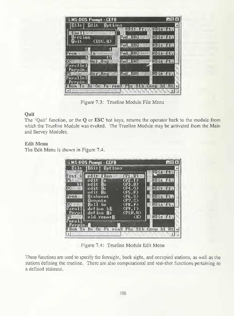
a MS-DOS Piompt - CEFB ESfclOj
Figure 7.3: Trueline Module File Menu
Quit
The 'Quit' function, or the Q or ESC hot keys, returns the operator back to the module from
which the Trueline Module was evoked. The Trueline Module may be activated from the Main
and Survey Modules.
Edit MenuThe Edit Menu is shown in Figure 7.4.
MS-DOS Piompt - CEFB
edit medit medit |bedit %iifc*l<eoatm)Vi\iixtil
lull hvdef U-ti h|id«sf hm itold ruifiuM
<F7,C>
<Fv,r><VUKH>
<K>
Parail|
P«rpi
|
ParallJ
rfftiw to Bs Pc -Fs frettp'Far- atK- Cartm
OklEi!
4
Figure 7.4: Trueline Module Edit Menu
These functions are used to specify the foresight, back sight, and occupied stations, as well as the
stations defining the trueline. There are also computational and test-shot functions pertaining to
a defined stakeout.
106

Edit Functions
The following edit functions may be performed at any time in the initial screen of the Trueline
Module. These functions allow the user to alter or change all of the station fields shown in the
initial screen of the Trueline Module in Figure 7.1. The edit windows for these functions are
eight characters long and have the same appearance and functionality as the BS station window
prompt shown in Figure 4.29.
edit fRomThe 'edit fRom' function, or the Fl or R hot keys, allows the operator to alter or change the
currently displayed From station.
edit ToThe 'edit To' function, or the F2 or R hot keys, allows the operator to alter or change the
currently displayed To station.
edit Bs
The 'edit Bs' function, or the F3 or B hot keys, allows the operator to alter or change the
currently displayed Back sight station.
edit OcThe 'edit Oc' function, or the F4 or O hot keys, allows the operator to alter or change the
currently displayed Occupied station.
edit Fs
The 'edit Fs' function, or the F5 or F hot keys, allows the operator to alter or change the currently
displayed Foresight station.
Stakeout
The 'Stakeout' function, or the ¥6 or S hot keys, allows surveyors to search for the two closest
station ID's for the BS and OC stations based on a defined FS (point to be staked) station. The
'Stakeout' function prompts the surveyor to define the station to be staked out. This prompt is
shown in Figure 7.5.
107

MS DOS Prompt - CEFB
Hi It; Edit m;t loiiiS
*"-"-"-'---- ..,-.•...,.
Figure 7.5: Station to be Stakeout Prompt
This function enables surveyors to define specific strings and/or a search radius in the search for
the OC and BS stations. This can be helpful, for example, when searching for the closest traverse
stations to a monument which needs to be staked out. The prompt to proceed with the define
search is shown in Figure 7.6. If a defined search is not selected, the 'Stakeout' function will
return the closest station to the OC field and the second closest station to the BS field.
MS DOS Prompt - CEFBHile Edit mat ion
BErlOi
.........;.;... •... :•****++*>j**.;*j^
Figure 7.6: Defined Search Prompt
The search for stations can be defined one of two ways. The first way is to select one of the
prefixes from the index file. This will result in only stations matching the selected prefix in the
BS and OC fields. Once the surveyor proceeds with a defined search, a pick list, as shown Figure
7.7, of available features and their corresponding prefixes is displayed.
108

MS DOS Prompt - CEFB
Pile Idic options^Z—4fK^N0*K?=^|i MOHJPPJtfONE-MFSIMGN...FD...WOOD HFU
! Ii'£imtiNfcNX i&"FBg
! KonB-iiD
MUMHUMMU*iimimUEBSE-STfl
'arAllelPeypin ..
jritow 10
6T0HEJUALJ«'*8U8U0HJMWFTOFO...Cftl<L -10
UTILITIES UTL
l.lliW Ii lliia ilM .MIIIMIIIMIhillMIMlMMIIMI IhlW^hW MM
^Wftrtii.niN.i
Figure 7.7: Index Pick List
This can be extremely helpful when a surveyor is extensively using automatic point indexing, and
he or she want to return only a particular feature to the BS and OC field. For example, a surveyor
wants to stakeout station 'SETT, and he or she only wants to return traverse stations to the BSand OC fields. Selecting the TRAVERSE-STA feature from the pick list shown in Figure 7.7
will perform that function. See Chapter Nine for automatic point indexing.
The second search method is to define a specific search string. This is accessed with the ESC key
in the pick list in Figure 7.7. This allows the surveyor to manually define the string to be
searched for in each station. This prompt is shown in Figure 7.8.
MS DOS Piompt - CEFBMile' Edit mitioiti
Bfc!n I
I HDio ft. HDis ft.'est Shot? |_'8 HorJina PwdL.BRG HBis
y'lM'HH I HIIMMttWmHtHH tfWW MMMKM I MI II I I <|IMMIMIMI MM I IMI Ml l l ' l' l l l
: :v£v:::£;£: :::
:
:
:
:'*"'':>\ ':':':'':'. -.•'
.-.-!'.
'
:
::':':':x'-: :
::;-;
: :-: : :-: :x ::
:
:: :-:'
; ':
String to look fo** in Statioo* ?
W\ffl.MM'JffiO *
.' «
"
' " *'
'
*
'
*.
'*? '
"
»
"
*h i
'
. i
'
i?i t i iiii \ i i>> t t i i
'
i4Wt;V i-'^*H *y^^
Pey;t>:t.»
»
Fara!leiPeymin
„
fRo« to B
..M.I
Figure 7.8: String to be Search for Prompt
109

The next step in a defined search in the 'Stakeout' function enables surveyors to fix the limits of
the search area from the stakeout station ID. The prompt requesting this procedure is shown in
Figure 7.9.
Figure 7.9: Define Search Distance Prompt
If the surveyor accepts the defined searched distance prompt, he or she is then asked to define the
search distance as shown in Figure 7. 10.
Figure 7. 10: Search Distance Prompt
The distance in the prompt in Figure 7. 10 will always match the defined output units. The default
distance for the prompt in Figure 7.10 is 1000.00. The two closest stations that meet the
requirements specified by the defined search will be returned in the BS and OC stations fields.
If only one station ID meets the defined requirements, it is returned in the OC station field and
the BS station field remains empty.
110

Figure 7.11 shows the results the 'Stakeout' function, defining 'SETT as the staked out station,
TRAVERSE-STA feature, and a 500.00 foot search distance.
MS-DOS Prompt - CEFB
lile Edit iotlti
mmn\
,iusfttiftifiiZkiktitilt£Ji
Figure 7.11: 'Stakeout' Function Results
ComputeThe 'Compute' function, or the F7 or C hot keys, allows surveyors to define any and all fields
before any computations occur. Once the desired fields have been defined, 'Compute' will
process the calculations and produce the screen shown in Figure 7.12.
MS-DOS Prompt - CEFBfile Edit ©tit ion
iBPi
^y/aiy/-»^i:-y.,a^^;.;.j-.v.y/J:.y,a:.vJ: ;•::.: ,:: . :-.jj j
:-. ,y,y,yy,y,yy.-syyyyyy. :-::-::-, yyyyyyyyyyyyyyyyyyyyyyyyyyyyyy^
Figure 7. 12: Computation Screen
The < Enter > key will return operators to the initial screen of the Trueline Module and blank
the computational fields. Station fields may not be edited until < Enter > is pressed. Note:
Functions in the computation screen may only be invoked from the hot key bar.
Ill

Pollbs
The 'Poll bs' function, or the F8 or P hot keys, creates a setup in the Trueline Module, and allows
the surveyor to poll the BS of that setup. This function leads into the 'Obs-tshot' function within
the hot key bar on the computation screen in Figure 7.12. The 'Obs-tshot' function will be
described later in this section. The 'Poll bs' function can also be invoked in the computation
screen in Figure 7. 12. For the 'Poll bs' to correctly create a setup in the Trueline Module, the
BS, OC, and FS must all currently exist in the coordinate (.cr) file. If this is not the case the
operator will be presented with the prompt shown in Figure 7. 13, and returned to the main screen
of the Trueline Module with out creating a setup.
MS DOS Pfompt - CEFB
iiile Idle ilifcisKi
mmni
^^--•^w .w:;>& |:>:\ V?\ > :^ >& •% -.?\ ''% '
:::i> -% % '<:'*£&+&.; riYni.Wi..v».w.v.«i< *->..-.-••»M^^.^a.-^>^.^wm* i^ .
Figure 7.13: BS, OC, or FS not in Cor File
Once the BS, OC, and FS stations in the Trueline Module are defined and are in the coordinate
(.cr) file, the operator is presented with the prompt in Figure 7.14.
MS-DOS Prompt - CEFB
mi ie id it iis t ion
:
iiOl
yr^fpil Ha.U« sa**c &*OM*ws lepluHg
mm
£LW&\ i(i- v<>«i% backs xj/tifc f
Pascal
rcp hi Ht
Figure 7. 14: Make sure you're looking at the BS
112

Once the BS station has been observed, a setup is created in the Trueline Module, and the main
screen of the Trueline Module has the appearance shown in Figure 7. 15.
MS-DOS Prompt - CEFBmile Edit Ob& ion
W$\zi K3
;
,.-.>ii-i;i,M.-..<.tf.rtffv •:> :> : -v -':-•- ^ -^ Vv
^ppgife liiilJJ /
Figure 7.15: Trueline Module after 'Poll bs' Function
define hi
The 'define hi' function, or the F9 or I hot key, allows the surveyor to redefine the height of
instrument (HI) for the OC station once a setup is created in the Trueline Module with the 'Poll
bs' function. The current height of instrument is 5.00 shown next to 'OC field in the sixth line
of Figure 7. 15. Figure 7. 16 displays the 'define hi' prompt.
:s MS-DOS Prompt - CEFBM i ie Id it my t ion s
Bid 13 i
Figure 7. 16: 'define hi' Prompt
113

define HtThe 'define Ht' function, or the F10 or H hot key, allows the surveyor to redefine the height of
target (HT) for the FS station once a setup is created in the Trueline Module with the 'Poll bs'
function. The current height of target is 5.00 shown next to 'FS' field in the fourth line of Figure
7. 15. Figure 7. 17 displays the 'define Ht' prompt.
i MS-DOS Piompt - CEFB
t ifotions
mnn\
&Jb mS^>-S-&>
Figure 7. 17: 'define Ht' Prompt
Figure 7.18 displays the main screen of the Trueline Module after defining the HI and HT to be
5.55 and 5.25 respectively. It is also important to remember that both the 'define hi' and 'define
Ht' functions can be invoked from the hot key bar of the computation screen shown in Figure
7.12.
MS-DOS Prompt - CEFB
liltt Id it ©tttion
KftsIO
VnW.LHH.iimnnili *—*—.«.»
Figure 7.18: Trueline Module after 'define hi' and 'define Ht' Functions
114

Obs-tshot
The 'Obs-tshot' function can only be invoked from the computation screen of the Trueline Module
with the O hot key from the hot key bar. The 'Obs-tshot' function allows surveyors to observe
a rod location, and acquire offsets from the rod location to the line between the OC and FS
stations in the Trueline Module. This can be a very useful function when staking out a corner
move. The 'Obs-tshot' function returns three offsets values to the third line of the computation
screen.
Right or Left Offset
The first value gives the perpendicular distance from the rod location to the line between the OCand FS stations. The R for right or L for left offset give the direction in which the rod needs to
move in order to place the rod on the line between the OC and FS stations from the instrument
person's perspective. The R or L character is positioned directly on front of the right or left
offset distance on the third line of the Trueline Module.
'-' or < + ' Offset
The second value gives the distance from the computed perpendicular position from the Right or
Left offset to the FS station. The '-' for right or ' +' for offset gives the direction in which the
rod needs to move in order to place the rod at the FS station location from the instrument person's
perspective. The '-' offset indicates the rod needs to move towards the instrument, while the ' +
'
offset indicates the rod needs to move away from the instrument. The '-' or ' + ' character is
positioned directly on front of the '-' or ' + ' offset distance on the third line of the Trueline
Module. Figure 7.19 illustrates the four possible offset scenarios for the 'Right or Left' and '-
or +' offsets.
115

p FS
»»«.i
Right '+' Offset
FS
*^o
^O
Right '-' Offset Left '-' Offset
O Rod Location Right Offset Value '-' Offset Value
© FS Location — — — Left Offset Value '+' Offset Value
Figure 7.19: 'Right or Left' and '-or +' Offset Scenarios
116

Up or Down Offset
The third value gives the distance in which the rod needs to move to match the elevation of the
FS station. This is where the 'define hi' and 'define Ht' functions come into play. The (HI) and
(HT) values must be accurate to receive a correct value for this offset. The Up offset indicates
the rod needs to move up to match the FS elevation, while the Down indicates the rod needs to
move down to match the FS elevation. The U or D character is positioned directly on front of the
Up or Down offset distance on the third line of the Trueline Module.
Obs-tshot Example
The horizontal right angle and distance from the OC station (16) to the FS station (SET1) is
292°34'35" 92.929 ft. from the computation screen shown in Figure 7.12. Based on that
information, the rod person paces out to that general location. The instrument uses the 'Poll bs'
function to create a setup, observe the BS station, and set the horizontal angle to zero. The
instrument then dials 292°34'35 into the instrument and puts the rod person generally on line.
Then, from the computation screen, the instrument person uses the O hot key, from the hot key
bar, to observe the rod location. Once the observation is complete, the offset values and
directions will be returned to the third line of the computation screen. For this example, let's say
the elevation of station 16 is 128.908 ft., the elevation of station SET1 is 130.12 ft., the (HI) is
5.55 ft., the (HT) is 5.25 ft., and the observations to the rod are 292°50'30", 89°30'30", and
86.50 for the horizontal right angle, vertical angle, and slope distance respectively. Figure 7.20
displays the result of this scenario.
Figure 7.20: Obs-tshot Results
117

Based on the assumptions noted above, Figure 7.20 indicates to the surveyor that the rod person
needs to move to the left 0.401 ft. and back up 6.433 ft. to arrive at the FS station location.
Figure 7. 19 also indicates that the rod needs to move up 0.170 ft. to match the FS elevation. The
instrument person relays that information to the rod person, and the rod person makes his or her
adjustments. The instrument person puts the rod person on line with a little more detail and uses
the O hot key to update the offset values and see how close the rod person is. The O hot key for
the 'Obs-tshot' function can be utilized as many times as necessary to position the rod person at
the FS location.
Once the FS station location is determined with the 'Obs-tshot' function, the surveyor can save
the last observation to the rod to the field (.ff) file if desired. This can be very help, for instance,
when a surveyor is setting a monument. The surveyor uses the 'Obs-tshot' function to determine
the FS station location. The monument is set, then the instrument person locates the rod on the
monument to see the proximity of the monument to the computed position. This last observation
to the rod is saved to the field (.ff) file.
Observations are saved to the field (.ff) file with the 'Obs-tshot' function in the computation
screen with the S hot key. The operator is notified of the save option after a test shot has been
taken with the S-save obs text above the Test Shot: text on the second line of the computation
screen.
Surveyors would not want to save a observation to the field (.ff) file with the S for S-save obs
option which is not close to the desired FS station (large offsets). Because of this, observations
with offsets larger than 0.20 of the defined output unit, that are attempted to be save the field (.ff)
file will produce the prompt shown in Figure 7.21.
13 MS-DOS Prompt - CEFBHilfc Edit ifttioft:
?st shot; imwxeb firm U
Sure yeu wane tu Save Ofou*
t5Bl3l
0.178
Offsets hank Pretty Big 91.063I
' --=1*551 i«
* 97.051
42 v 61
3
54.377liii T MJBO Wis ft
nta** to uontV Phs'
; 01ws:-:
t8!Jw>t*%<«!
j
Figure 7.21 : S-save obs Trap for Large Offsets
118

old remarKThe 'old remarK' function, or the K hot key, displays a pick list of available feature codes in the
feature code file. This function is described in detailed in the setup menu section of Chapter Four
(Survey Module).
Options MenuThe Options Menu is shown in Figure 7.22. All of these functions have been described in detail
in earlier sections. The define output Units function is described in the option menu section of
Chapter Six (Cogo Module), while the change Angular disp. and FwdVMean disp. functions are
described in the Display Menu section of Chapter Three (Main Module).
OblOi
jBMaflaaBMftMftiB'B
Figure 7.22: Trueline Module Options Menu
119

CHAPTER EIGHT - CEFB - Read/Edit Module
Overview
The Read/Edit Module is where observations and field descriptions in the field file may be
reviewed and/or edited. The main screen of the read/edit is shown in Figure 8.1
13 MS-DOS Piompt - CEFB mmu\iFia£;.;.:...;,Eait Di&al&tf
........... ............. ..............
FufdJBRG ftode Fud.B!K>
MtJci&wi'feU
iHjftng*jz fins
J Bis
Jrfean A....He.;tf}
Tue Jul 81 02:31 !51 1V97 CEPT ~4>
arm Next Previous ESC yE»d^ye» Go_to__ -
Figure 8. 1 : Read/Edit Module
The look of the Read/Edit Module is very similar to the Survey Module. However, the pull-down
menu and hot key bar contain slightly different functions. There is also an additional area below
the defined BS station name which indicates the status of the observation. Observations mayappear as unedited, 'DELETED', 'UN_DELETED', or 'MODHTED'. The status of edited
observations are indicated in the observation (.obs) file with the D, U, and M characters directly
following the setup 'S' and foresight 'F' records.
As described in earlier sections for the Survey and Astro Modules, the arrow keys are used to
scroll through observations. The up and down arrow keys are used for scrolling through
repetitions, while the right and left arrow keys are used to scroll through foresight stations.
*N* for Next and T' for Previous
Unlike the data collection modules, the operator may scroll the various setups of the defined field
file. The letter 'N' (next) scrolls forward through the setups, and the letter 'P' (previous) scrolls
backwards through the setups. These functions can only be accessed through the hot key bar.
File MenuThe File Menu is shown in Figure 8.2. All of these function have been described in earlier
sections and are common functions in CEFB. The open Field file, Open coord file, Shell, and
Version functions are described in the File Menu section of Chapter Three (Main Module). The
Trueline and Cogo functions are described in the Function Menu section of the Chapter Three
(Main Module). The Quit function, or the Q or ESC hot keys, quits the Read/Edit Module and
returns the operator to the Main Module.
120

vi MS-DOS Prompt - CEFB OlxJ O;
%F$Ml E&it M&plM''T\"
»* » —~iQfi3ii;B 1KSSo«en Field f.i'iw
yO)p««v coord file
T>u«lino
> lie pi! Hi <« -»>1;S«Airfreight
fxte Pud BUG
Tue Jul 81 8?:J3:4& i'i'/? <FJDI
«enu next: jrj*ow3M>MS fcsu *t^M**.$91£$.i.
»«—J
;.;y.v,y;/y,v./ , .y,sy.^v< y, /,
.
:::. yyyyys.ysyyyyyy/.yyyyys^ ,vy..\ <>yyy/yyyyy
J
Figure 8.2: Read/Edit Module File Menu
Edit MenuThe Edit Menu is shown in Figure 8.3. The functions in this menu are used to edit or modify
observations and descriptions in the field file. Observations deleted, modified, or un-deleted using
the following functions are not removed from the field file, but are flagged as either deleted,
modified, or un-deleted with characters ('D', 'M\ or 'U') identifiers called flags. The flags
identify which observations should be recognized or ignored by CEFB and the post-processing
program TOLSA.EXE.
13 MS DOS Prompt - CEFB too!VWmmmBac it c- ill vd.it Bs
&i££3&
itiight
setup
<EG* to oce, *ta. <0> WJJ*
a n«a«+& %*\WVm ,
:
'*,
:tn *mil h i t ii tin h m i h h i m"*.m,m i i i immm i n 1 1 »i i n 1 it im i i i i mii'im i
Tae Jul m 09:35:24 1997 <EWl
term Next: Previous ESC rEad_re» Go„to
Figure 8.3: Read/Edit Module Edit Menu
121

edit Bs
The 'edit Bs' function allows the operator to re-name the BS station with a standard station name
window. The setup will be tagged as MODIFIED in the Read/Edit Module, however, both the
original and MODIFIED versions of the setup 'S' record will be in the observation (.obs) file.
Editing the BS station will also affect all observations within the current setup. For instance,
changing the BS station name will result in the horizontal circle readings of the foresights for the
setup to be computed from the new defined BS station name. This will also effect the coordinates
of the observations for the setup. Below is a example of the original and modified versions of a
setup 'S' record with the edited BS station.
10 20 30 40 50 60 70 80 90
123456789 123456789 123456789 123456789 123456789 123456789 123456789 123456789 123456789 12..
S STA1 STA2 5.500 Fri May 11 07:41:53 1997SM TRAV1 STA2 5.500 Fri May 11 07:41:53 1997
edit OcThe 'edit Oc' function allows the operator to re-name the OC station with a standard station name
window. The setup will be tagged as MODIFIED in the Read/Edit Module, however, both the
original and MODIFIED versions of the setup 'S' record will be in the observation (.obs) file.
Editing the OC station will also affect all observations within the current setup. For instance,
changing the OC station name will result in the horizontal circle readings of the foresights for the
setup to be computed from the new defined OC station name. This will also effect the coordinates
of the observations for the setup. Below is a example of the original and modified versions of a
setup 'S' record with the edited OC station.
10 20 30 40 50 60 70 80 90123456789 123456789 123456789 123456789 123456789 123456789 123456789 123456789 123456789 12..
S STA1 STA2 5.500 Fri May 11 07:41:53 1997SM STA1 TRAV2 5.500 Fri May 11 07:41:53 1997
edit Fs
The 'edit Fs' function allows the operator to re-name FS station and HT (if the HI/HT prompt is
activated). This particular FS station will be tagged as MODIFIED in the Read/Edit Module,
however, both the original and MODIFIED versions of the foresight 'F' record will be in the
observation (.obs) file. Below is a example of the original and modified versions of a setup 'F'
record with the edited FS station.
10 20 30 40 50 60 70 80 90123456789 123456789 123456789 123456789 123456789 123456789 123456789 123456789 123456789 12..F SS01 2 5.000 21 15 25.0 272 08 10.0 145.630 0.000 Fri May 11 07:43:57 1997FM SS02 2 5.000 143 59 47.0 267 59 55.0 225.050 0.000 Fri May 11 07:44:57 1997
edit ModeThe 'edit Mode' function allows the operator to re-define the instrument measurement mode for
a FS observation. Figure 4.32 displays the prompt for this function., the operator is prompted
to choose from three possible modes. Below is a example of the original and modified versions
of a setup 'F' record with the mode changed from HVF to HV.
122

10 20 30 40 50 60 70 80 90
123456789 123456789 123456789 123456789 123456789 123456789 123456789 123456789 123456789 12..
F SS01 2 5.000 21 15 25.0 272 08 10.0 145.630 0.000 Fri May 11 07:43:57 1997
FM SS01 5.000 143 59 47.0 267 59 55.0 225.050 0.000 Fri May 11 07:44:57 1997
Delete entire setup
The 'Delete entire setup' function allows the operator to delete all observations from every
repetition related to the current setup. All observations in every repetition of the current setup are
marked as deleted. The warning for this function is shown in Figure 8.4.
MS-DOS Prompt - CEFB BEfo;
PmJLJ9R
<t 4>ltep*t
ZjBns
u Ms' " ' *
-'r%;:-n*i..- -:\-:-:*% nnnWHII
Tue Jul 81 89:35:24 %*}9? <Bjl
LJ-.J.
<^P?kHou^S<H'E!?TTHH?o^o^^ -1
*».«..««**— IMtoM ».-.
Figure 8.4: Delete Entire Setup Prompt
delete Fs from setup
The 'delete Fs from setup' function allows the operator to delete (attach a 'D' delete flag) the
currently displayed FS observation from a setup. The prompt for this function is shown in Figure
8.5.
.'DiiSift'Iaiii
MS-DOS Prompt - CEFB
Backs is'iifc ForesightFud.'..BRG r
olslKs
4
Delete
HIJ&is
H .^.^HH^ ***
A...!"!«;<«'*
+0°00 88
8»*l0i8Tue Jul 81 89:48:83 199? <EBT 4>
Next F**ev!a«s WC vma~j*em w~b#
Figure 8.5: Delete Observation Prompt
123

Un-delete fs
The 'Un-delete fs' function allows the operator to un-delete a previously deleted FS station
observation by replacing the 'D' deleted flag with an 'U' un-deleted flag. The prompt for this
function is shown in Figure 8.6.
Ti MS-DOS Piompt - CEFB
Bat ks ight Fo-yes iffhtFwd...BRG
™lsi F~>
r il
tlnjtelete this OBS ?
H_ftng2. fto«
II3is
NOtHWWW tHUH
A.„J1«<xn
:>•'
:•: ^^^'•-•''-'>x<*:-:->:<-:v:-:-:-/'':-;-:^<-y.<-;>:-^^^B .:-:: :::: :-:<'/.<•:•:<<«•>:
Tue Jul 81 89:45 ?53 V19? <EDT 4>
JMMMI^^Mi^^•J
;xiSJgiggfgggg::::;:;:;:^::;:
vious ESC rEad_yew Go„to
y. :.,.: .-*..;y...-s.::-;. .,.-. .;,.-: :-. _.,:•:-._ . :-.-:-. .•^:-:-:-:-m:-m;.;^
Figure 8.6: Un-Delete Observation Prompt
If the operator attempts to un-delete a FS observation which is not deleted, the prompt in Figure
8.7 will notify the operator that the observation can not be un-deleted.
? MS-DOS Piompt - CEFB BBn-WiM* Edit }>U*U&~ Wgm®
Pores :fc¥htM l t ftftMMttMMMtl tMM tim t l l HIMHtHlti tl M'
Cannot tlKJDEUSTE this OBS t
HJtalZUBn
«i»t*tH «+Mm
OK I
Tue Jul 81 8?; 47: 38 1997 <EBT
vrmHextTvelnx>u^
-—..«.. .... I...JM M» , I
Figure 8.7: Cannot Un-Delete Observation Notice
rEad remarks
The 'rEad remarks' function, or the E hot key, facilitates the viewing and editing of descriptive
remarks collected in CEFB. This function is a crucial segment of field note production discussed
in detail in Chapter's Twelve and Fourteen. The 'rEad remarks' produces a pick list of available
stations with descriptions. This pick list is shown in Figure 8.8.
124

MS DOS Prompt - CEFB
«2 Fmm.jmi air.
%2 nm\..miaii
ftNT PROM THIS:
BBE3I
"X*:":-.:'';':-.
SFF7 CBP:SF17 FRoriJiHiCH:8ET6 ^T:SFT6 N0N...SET:8ET6 GAP;SEi'6 FKOrUftUCIf:
s.<^^-^SSSSSSSSS^SSS.<,-.-VSSSSSSSSA
Figure 8.8: Read Remarks Pick List
The pick list in Figure 8.8 displays the station name the description is attached to, and the
identifier of the description. If the description is a free form remark (no identifier), the first 20
characters of the remark will be displayed to the pick list. When a station is selected its associated
description is displayed at the top of the screen as shown in Figure 8.9.
vs MS-DOS Prompt - CEFB BBOisew •
jSet an ftiurdnufi post* 30 int?. long- 2jl/2 ins- cii«\ft..ft .18 ios. in the ground, ...
!»yeis « "MEF"J. ,>, :i.a> ...«*...<;» Has* of stone, 1
jff. high.. 3 ft, KiiiUj, with &n iilup^irmn ...
cap wiuK
any
^^i¥r..i..Vn. t
Figure 8.9: Read Remark Screen
As the hot key bar states on the last line of Figure 8.9, the 'E' character key will allow the
operator to edit the description with the edit window shown in Figure 8. 10, or any other key will
return the operator to the main screen of the Read/Edit Module.
125

M S D S Piompt - CEFB MBSEX?Set an aluninun poat, 38 ins, lon<^ 2 __.1/2 ins. dxaral, 18 inn. in tlie ground* ...
»ve*» a "CJBEP 1 "„ ifiw>«.jcallftr oi stone- IFti high* 3 ft. wide,, witla an aluriinun ...
cap RktLi
Figure 8. 10: Edit Remark Window
The surveyor can view the original remark and the edited remark at the same time. The edit
window at the bottom of Figure 8. 10 has several editing keys that facilitate elementary editing.
The right and left arrow keys allow the operator to scroll up and down the chain string to get to
the desired location. The HOME and END keys places the cursor at the beginning and end of
the description, and the BACKSPACE and DELETE keys also work accordingly. The original
remark is flagged as modified (RM instead of R ) with the edited version directly below it in the
field (.ff) and observation (.obs) files as shown below.
RM SET7 MON_SET: Set an aluminum post, 30 ins. long, 2 xh ins. diam., 18 ins. in the
ground, over a "DEEP-1", in_a_collar of stone, 1 ft. high, 3 ft. wide, with an aluminum cap
mkd.
R SET7 MON_SET: Set an aluminum post, 30 ins. long, 2 lh ins. diam., 22 ins. in the
ground, over a "DEEP-1", with an aluminum cap mkd.
Go to occ. sta.
The 'Go to occ. sta.' function, or the G hot key, allows the surveyor to directly select the setup
he or she desires to manipulate. This function is achieved through a pick list shown in Figure
8.11.
126

MS DOS Piompi - CEFB BKini
Backsight',Fud„JBRG
ii...M;;l
.'ue J
i 2-32-3-43-4-i'i4-S-KET'l4-5-HRlB1--B2'~B3
l~.t234S6?fMI
M..EHG*
:
|>^:?f:f|*:
«J
WfMmwm
A.Httao
k Next Previous ESC rEad_t»ew Go_to< 1
'
"
997 <EDI
aaaBaaaMMi jajawafl n,.*.rf...«iY.«.i.«V.M .»*.*<......< *.«<-.»
Figure 8.11: Go_To OC Station Pick List
Each selection in the pick list in Figure 8.11 displays the BS, OC, and first FS stations for each
setup in the field (.ff) file. Once a selection is made, control is brought to that setup in the
Read/Edit Module. The file position stays at the selected setup. This can be very useful for
obtaining the desired setup quickly instead of using the Next or Previous functions to scroll
through a large number of setups.
Display MenuThe Display Menu is shown in Figure 8. 12. The two functions in this menu have been described
in detail in earlier sections. The change Angular disp. and FwdVMean disp. functions are
described in the Display Menu section of Chapter Three (Main Module).
"S MS-DOS Prompt - CEFB otEIOl
it? plQpgf *
Backs ijjJifc
Pud.,.BRG
Z Anc/
HJDisI* B:U
iinnimrvd Hear*
[ue Jul 81 89:56^1 m? <EDI9.000
1e«tt^ftextx F**wi<w$*mC • *»Eaa„jt»e« GoLfco
A
Figure 8. 12: Read/Edit Module Display Menu
127

Updating Coordinates in the Read/Edit Module
When a operator utilizes the 'edit Bs' and 'edit Oc' functions to edit the BS and OC stations of
a setup, this can clearly effect the coordinates for that setup as well as consectutive setups. Anexample of this can be the wrong BS station in a series of traverse setups. To correctly update
the coordinates of subsequent setups once the user has edited the BS or OC stations with the 'edit
Bs' or 'edit Oc' function, he or she must use the 'Next' function from the hot key bar. As the
operator scrolls through each subsequent setup, the coordinates for the observations for each setup
will be correctly updated.
128

CHAPTER NINE - CEFB - Automatic Point Indexing
Overview
The primary reason for blunders in surveying is station identification (ID or naming). The feature
code (.fc) file categorizes descriptive features utilized by the surveyor during field data
collection. Automatic point indexing extends that same philosophy into the back sight (BS),
occupied (OC), and foresight (FS) station ID's, and the collection of numerical and descriptive
data for those stations. The feature code can now drive the station ID's. For example, every time
a surveyor locates a fence, after the FENCE feature is chosen the corresponding station ID is
produced and automatically indexed. This concept is also incorporated into the descriptions of
stations ID's. If the surveyor knows the feature defined for a station ID, there is no need to scroll
through a pick list of feature codes. For example, if the surveyor desires to describe a FENCEstation ID, he or she should have the ability automatically execute the corresponding FENCEfeature code without the use of a pick list.
These concepts are implemented with the use of an Index File. The index file, (.ind) extension,
is created with any text editor in the same fashion as the (.fc) Feature Code File. Features
defined in the index and feature code files will drive everything you now do in CEFB.
The Index File
A correctly formatted index (.ind) file has three fields: the prefix, the identifier (feature code),
and the suffix in that order respectively. The prefix is 1 to 4 characters (no numbers), which
usually is an abbreviation of the feature code name. The identifier is the tie or pointer to the
feature code file, and is identical (also with regard to case) to the feature code identifier.
Identifiers in the index file do not necessarily have to match identifiers in the feature code file,
however, identifiers that do match fuel automatic descriptions of station ID's. The suffix is the
counter, or the number, of the next shot of a particular feature. The number is incremented
automatically after every location of that particular feature. The suffix is not incremented for a
particular feature until the observation has taken place. Figure 9.1 displays an example of an
index file.
129

Identifier
Prefix Suffix
B BUILDING 1
BT BEARING_TREE 1
CON CONTROL 1
CRK CREEK 1
F FENCE 1
FWF FROM_WHICH_FD 1
L LAKE 5
LT LINE_TREE 2
MFC MON_FD_CON 1
MFP MON_FD_PIPE 2
MFS MON_FD_STONE 1
MFW MONFDJWOOD 1
PBS PERMANENT_BS 6
RD ROAD 1
RIV RIVER 1
RR RAILROAD 1
STA TRAVERSE 29
SW STONE_WALL 1
SWP SWAMP 1
TC TOPO_CALL 1
UTL UTILITIES 1
Figure 9.1: Index File
Station ID's defined through the index file combine the prefix and suffix. For example, the next
location of the BUILDING, LAKE, and MON_FD_PIPE features in the index file in Figure 9.1
would be Bl, L5, and MFP2 respectively.
The STA prefix is a flag for simple integer station ID's, which are commonly used for traverse
station ID's. The STA prefix is never attached in the production of the station name. The station
ID becomes the suffix counter itself. For example the next shot for a TRAVERSE identifier will
be 29.
Main Module
The Main Module of CEFB has two functions that affect the index file. The Main Module
appears in Figure 9.2.
130

la MS-DOS Prompt - CEFB mBn\WiteW:Ovi;ifyri& 'Fuhetibtt Dia^iSTy"
Fie id Fxie* TESI.FfCoord File. IF^I.CIIP„..Code File. CFFBPFF-FClii&ux File. CEFB .INI)£P€8 fitytua.; HBD27SPC8 Statu;.* tteine
Ertcji
&Jed Jul 16 12j86;27 1997 <0XCterm Swevej*
.««t,**o. Cos* Tme p«4 I««tr«
toclw EeM stttFlchn mtvMmff Ttef UnitsJ 1
A
Figure 9.2: Main Module
The Main Module lists the user defined files. The file pull-down menu is shown in Figure 9.3.
IS MS-DOS Piompt - CEFB
,.l. . . -:
I ,. . . . .,;.,. , „ ,.,,....„ ; ...,.-, $&&&si£g
MM file
rao
•*" - .,.—,.,---
%?m zoua
TESI.FFCTl^T-CSI
CFFTJPFF.FC;CEFlLINDimm?tint hiit)
fe«S Jul " is* lYsal'ssf IvW <oi clentt ««^vej/ B^tj^o Cosr» Xx*u& mm. Imbvntaelw Eclm «t»Pi:c]w aLlcJbnsof£ D»f "nits!
Figure 9.3: Main Module File Menu
open Index file
The 'open Index file' function shown in Figure 9.3 opens an index file and loads it into memoryfor automatic point indexing. The prompts for the open index file function operates in the same
fashion as the other open file prompts described in Chapter Three. If errors are found in the index
file during loading, an error message will notify the surveyor, and the index file will not be
loaded.
131

la MS-DOS Piompt - CEFB
r
V
Figure 9.4: Main Module Options Menu
Reset index counter
The 'Reset index counter' function under the options pull-down menu shown in Figure 2.5 sets
the suffix for all features in the index file to 1 . This is usually performed at the beginning of a
survey job to begin the automatic indexing of station ID's at 1. This function will only be
executed if an index file is loaded. You can not set the suffix to 1 if their are no features (.fc)
loaded.
MS DOS Piompt - CEFB
&>$«*; IMex Cowot «j»?
i««m « MH i Hn t
NOHIMHIHI I I
mM H»»frMM+M-H
WWHWtWwWl
\Am:-- • ~- -T
^rw M)ns*. East £ .
Ued Jul "16 '12:86 :&6 199? WIC 0>H©ou gurus^ H&tiH) Co0o Tj*«e Beaa instintt>ne>>yi Be1w s toFl c1m atlclhnsoff fief UnitsEE :r
Figure 9.5: Reset Index Counter Prompt
Figure 9.5 displays the reset index counter prompt. The user then selects his or her desired
choice. The yes selection resets the suffixes for all the feature in the index file to one.
132

Survey Module
Predicting Consecutive Acceptable Index Station ID's
Anytime the index file is loaded and a surveyor performs a function that prompts for a station ID,
that prompt will always attempt to predict the next consecutive station ID numerical suffix. This
routine requires acceptable index station ID's in the corresponding BS, OC, and FS stations. The
BS and OC stations are two fields where station ID's still usually need to be manually entered.
The first prompt when initiating the Survey Module is for the back sight (BS) station. If an
acceptable index station ID is entered into the BS station, CEFB will now predict the occupied
(OC) station to be the next consecutive index station ID for the prefix in the BS name. For
example, utilizing the index file in Table 2.1, if Bl is entered in the BS station, B2 will be
predicted for the OC station, and consequently B3 for the foresight (FS) station. Another example
of this are the integers associated with the TRAVERSE identifier. If 1 is entered in the BSstation, 2 will be predicted for the OC station, and consequently 3 for the FS station. One can
also change the prefix at the OC station. For example, if 1 is entered in the BS station, 2 will be
predicted for the OC station, but that 2 station ID could manually be changed in the OC station
prompt to B2, and consequently B3 will be predicted for the FS station.
It is very important to remember that this functionality is only a prediction, and manual input of
the BS, OC, and FS stations can always override those predictions. It is also important to keep
in mind that prediction of consecutive index station ID's has no bearing on the suffix for that
feature in the index file. The only time a suffix for a particular feature is incremented is when
an acceptable index station ID in the FS station is polled or observed.
Only character prefixes are allowed in the index file. Examples of unacceptable prefixes which
will not work properly if entered are F!l, 10A, BA2, RR2A. These unacceptable prefixes can
be entered and used as acceptable station names. The index file does not change the way station
ID's can be manually entered and managed. However, with the addition of the index file, the
surveyor can apply the prefix/suffix concept for more effective data collection.
Selecting an Indexed FS Station ID
Automatic point indexing of subsequent foresights at a setup is handled through a variety of
options.
133

MS DOS Prompt - CEFB EHxJDj
I. «— —
~
WA IVOR cov.II Bchn Onchn Brkclw Mode *~key Index
Figure 9.6: Survey Module Instrument Menu
The 'Index list' function, or the F10 or I hot keys, produces the pick list shown in Figure 9.7.
The pick list displays all of the identifiers, and their associated prefixes, available in the index file.
Selection of one of the features by pressing enter will produce its proper station ID, based on the
feature code prefix and the latest suffix. The index pick list has the same user interface as any
pick list in CEFB. Note the list can be searched alphabetically, press "R" and the first feature
code beginning with "R" is found.
s MS-DOS Piompt - CEFB OlElKli
rtea«
ZLAngHJDisUJDls
FII*rjnstr. Sftttm , Display Chain
CONTROL CONGKEEK~CHKFEHC£~FFItOfUJHlGII.JFD~FVFLAKE-LUHgJUUSiMJMON..JPB....GON-MFCHQHJFB.JPIFEHt1FPHOH.J<IT....S10HF.-nFSHON FOJJOftMIF-U
c
A. tiean
CUTG{ Nrera HSC
%:
Foil Bep _
Figure 9.7: Index Pick List
Selection of the MON_FD_PIPE feature in Figure 9.7 will produce MFP2 in the FS station if
the next suffix for MFP is identified as 2 in index file. Corresponding prefixes for features are
shown to enable surveyors to exactly identify which feature and prefix is desired, based on the fact
that surveyors can establish one or more features with different prefixes (discussed in the 'Load
chains' function of Chapter Ten and the 'aDding a prefix' function of this chapter).
134

Another method of invoking the index pick list is in the FS station prompt with the F10 key as
shown in Figure 9.8. When an index file is correctly loaded into CEFB, the FS station prompt
heading will be "FS Station or F10 ?" to signify to the surveyor of the capability for generating
the index pick list from that prompt.
MS-DOS Piompt • CEFB ilOjliiFiiiiiiimmmmwmm.
Backs iahtfts*ir..MW>
^BSBMy^Mod*
:* ^^B' 38" W»l
Figure 9.8: FS Station Prompt
The 'next Fs station' function in the setup pull-down, or the F hot key, invokes the FS station
prompt shown in Figure 9.8. This allows the surveyor to define the next FS to be observed for
that particular setup.
The functionality of the prediction of acceptable index station ID's is employed is this operation.
Whenever the 'next Fs station' function is invoked and there is an acceptable index station ID in
the FS station, CEFB will always predict the FS station to be the next consecutive index station
ID. For example, if RR5 was in the FS station, RR6 would be predicted for the next FS station.
This does not confine the surveyor to one particular feature. The F10 key in the edit FS station
prompt discussed previously enables surveyors to select the index pick list of features. For
example, if RR5 was in the FS station, RR6 would be predicted for the next FS station. If the
surveyor, however, desired to observe a FENCE location, the F10 key would bring up the index
pick list and allow the surveyor to redefine the FS station to the FENCE feature.
135

& MS-DOS Piompt - CEFB tSfclO!
raFiM I:
:^:
fS...—.....«». .....x.. —^ ...,.....».» ,..,—„.—^~^-^~-n
*KS SpllfP<I;3,.S>
Poll JtapSet old i»««a^K'.
*i
... ............... -... . . I ... . I W. . . . I . it .'',A'-V-''-'" - •- -
Figure 9.9: Survey Module Setup Menu
Moveup Segment of Next Setup Function
The 'next Setup' function in the setup pull-down menu shown in Figure 9.9, or the F3 and S hot
keys, prompts the surveyor if a new setup is desired. The surveyor is then questioned if the newsetup will be a "move up" from the existing setup. The move up option is based on the logic that
the new BS station is the previous OC station, the OC station becomes the previous FS station,
and the FS station is prompted to the surveyor for input. This function facilitates basic traversing
methods.
The disadvantage with this procedure is that the surveyor must always observe the next traverse
or occupied station last in the current setup, so that the move up procedure will correctly update
the BS and OC stations. For example, if the BS station is 1, the OC station is 2, the FS station
is MFP3, and the surveyor has already observed station 3 (assumed to be the next desired OCstation), the move up option would incorrectly position 2 in the BS and MFP3 in the OC station.
When the index file is loaded in CEFB and there is an acceptable index station ID as the OCstation, the move up option will be based on the OC station. This implies that the BS station
becomes the previous OC station, the OC station becomes the previous OC station index station
ID +1, and the FS station is predicted to be the previous OC station index station ID +2. Three
examples of this methodology are shown below. The resulting FS stations in these examples are
the predicted station ID's.
Example No.#l
Original Setup
New Setup after Move Up
Example No. #2
Original Setup
New Setup after Move Up
BS Q£ ES11 12 13
12 13 14
BS Q£ ES11 12 MFP312 13 14
136

Example No. #3
Original Setup
New Setup after Move Up
BS PC FS
Fl F2 RD1F2 F3 F4
The first two examples contain integer station ID's from the TRAVERSE identifier of the index
file. The resulting OC station is the previous OC station + 1 or 13, and the resulting predicted
FS station is the previous OC station + 2 or 14 in both examples. The same is true for the third
example, where the resulting OC station is the previous OC station + 1 or F3, and the resulting
predicted FS station is the previous OC station + 2 or F4.
This move up procedure is based on the concept that the OC prefix will remain the same and
increment by one, and the FS prefix will remain the same feature as the OC prefix and increment
by two. This does not occur all the time in the field, but it does allow surveyors to collect
traverse and sideshot data in any order without a FS station becoming an undesired OC station in
the move up option. This concept works best if a surveyor bases his next step on the occupied
station name prefix + 1. This would normally be the first foresight at a setup.
Automatic Descriptions
If the FS station is an acceptable index station ED, the surveyor has already identified what feature
the FS station is and should not have to scroll through the feature code pick list to execute a
description for the that station. The 'Auto remark' function, or the ¥6 or N hot keys,
automatically executes the feature code corresponding to the FS station prefix and attaches it to
that station. If there is not a corresponding identifier in the feature code file, or an acceptable
index station ID in the FS station, the generic description pick list functionality (normally accessed
by the K hot key) is performed.
The 'old remarK' function, or the F7 or K hot keys, displays a pick list of available feature codes
in the feature code file. Before this occurs the surveyor is asked to define the station to attached
the remark to. This prompt is shown in Figure 9. 10.
& MS-DOS Prompt - CEFB
Mean BKG Mode
EmlOspla y Chains
Foresight
Jtei*&**k attached to ?,
:;
-
•.-•
^'.'^".'." ' "^"'"'"".^" ' "' ^WW i tUHtHHUKi tH >«**>»*! t«*4m t*t«<
^tl ::
''
;
l>?M:
-
:
Obciw:/
B»Ji<olw Horie ~key JtiMk *'i
Figure 9. 10: Attach Remark Prompt
137

The default station (attach remark to default of occupied or foresight station) for the prompt in
Figure 9.10 can be defined in the 'set Default values' function discussed in Chapter Three. The
'set Default values' function stores several parameters utilized in CEFB in a configuration (.cf)
file which is initialized at the onset of CEFB. The OC and FS stations are the most commondescribed stations at the time of description execution, and gives the surveyor the ability to define
one of the two fields as the default station. The prompt is shown in Figure 9.11.
It MS-DOS Piompt - CEFB
>n« Turuey Astro Cogo True Head Inst:
Figure 9. 1 1: Attach Old Remark Default Station Prompt
Apoll
Observing and describing an acceptable index station ID in the FS station requires two keystrokes,
the P for Poll hot key and then the N for Nrem (New Remark) hot key. The 'Auto rem poll'
function, or the A hot key, reduces the require amount of keystrokes to one. The 'Auto rem poll'
function has the same functionality as the 'Poll' function except that the 'Auto remark' function
is immediately executed after the instrument is polled. This allows surveyors to automatically
describe the FS station based on the feature code.
The + or = Hot key
There are several instances in the field when a surveyor is collecting consecutive observations of
the same feature from one occupied station. Examples of this could be the collection of several
shots along a fence, road centerline, edge of pavement, top of fill, or a meander line. These
scenarios are generally associated with the collection of chains (linework) but can also be
consecutive point feature codes. The ' + poll key' function polls the instrument for measurements
and increment an acceptable index FS station automatically. The + hot key cannot increment a
different feature's suffix as it assumes that you are locating the same feature. The only condition
of the + hot key is that there has already been a set of measurements recorded for the first station
ID of that feature. The + key substitutes for the F10 and poll keystrokes.
138

As an example, assume a surveyor needs to locate a portion of a shoreline of a pond from one
particular station. The surveyor utilizes the procedures described above to select the WATERfeature from the index file and automatically place Wl in the FS station. The surveyor then
points and polls the instrument locating Wl. The rod person moves to the next location. Nowthat the first observation has been taken, the surveyor points the instrument and selects the 4- key.
The instrument is polled and the FS station is incremented automatically to W2. This process can
be repeated as many times as one chooses. The + hot key gives the surveyor the ability to collect
data very efficiently, thus keeping the rod person quite busy.
The '= poll key' function, or the = or W hot keys, is the Apoll equivalent of the 4- hot key.
The = hot key has the same functionality as the + hot key except that in addition the
corresponding feature code for the FS station is automatically executed after the instrument has
been polled.
Adding a New Prefix
During the course of a survey, it might desirable to add a prefix to the existing index file in the
field. A particular feature needed during the survey might not be included in the index file, or
one might need to creating a another prefix for the same identifier to facilitate locating two chains
of the same feature simultaneously (discussed in Chapter Ten). The 'aDd new prefix' function
provides the ability to add elements to the index file. The 'aDd new prefix' function has three
segments. The first segment defines the new prefix, the second segment selects or defines the
identifier, and the third segment defines whether to activate the new prefix and identifier for chain
collection. Figure 9.12 displays the first segment of the 'aDd new prefix' function.
& MS-DOS Piompt - CEFB RlEfOPile I n&t*. j>etup Display Cha
- 1 pPEHfnfli *' ifit I > lie pit §K£ O -OFS8Bac ha ig ht Fo r* c? £«htttean BKG node
Prefix
tf_Jtn MmWmmmm :;•;<
;
:
::•;\MmmmmmMmmm .
UJftis
MTiihttthii . t*tin *SShT iffi*** _
** iTttn i\ , ****** *t****Z
v.& Jul 81 10:48:16 1997 <EBTall mp »&n r& i»»ue u«9o »«.»».,.««*«««».«?..9mtl mm msm Brkefon Hod« ***k»y Infax
I
- - .-.-...-....•.-...-...:.- - -.-. ......
Figure 9.12: New Prefix Prompt
Allowable prefixes are no more than 4 characters, do not contain integers, and do not equal any
previous prefixes. Any prefixes entered that do not meet the prior criteria will not be accepted.
139

After the new prefix is defined, the second segment of the 'aDd new prefix' function displays a
pick list, similar to the one shown in Figure 9.7, of existing identifiers in the feature code file.
This allows the surveyor to attach the new prefix to one of the existing features. If that is not
preferred, the ESC key permits definition of a new identifier manually. The new identifier
prompt is shown in Figure 9.13.
WFW&&MMS-DOS Piompt - CEFB
<f 4>jfteplt H <<- *>FS8
Mean.JBKG Ho<l«
BBE3J
|
'
|! .
New Identifier $.
rtjft»9Z din
tfJDls
luBHWWm?t>m>HVH t>M' 'H I HI H it * I ** 1 1 « fHM i * 1 1 1 1 tif \
L TV&&i\
..^:'x :v: ;:V: ;v>^^H.-:>>v:-:v: :x::^;::-: : :-.-. . . .
::-:l?:*llii :
i?x»:» :
;l
Tue Jul &1 10:48:16 1997 <E»Troll IHep Set .f» T»«k» mm jp*ihK «**»« «$..,..
Spoil Echn Onchn Brkcltn Hode *-key TndexH4
Figure 9.13: New Identifier Prompt
Identifiers in the index file do not have to match identifiers in the feature code file, however, it
is important to remember that if the surveyor does not select one of the existing features in the
feature code file automatic descriptions will not be available for the new identifier. The pick list
of existing identifiers in the feature code file is displayed first to encourage their selection.
The third segment of the 'aDd new prefix' function is shown in Figure 9.14. The surveyor is
asked to define whether to activate the new prefix and identifier for chain collection. If the
surveyor does activate chain collection he or she must then define whether the chain is initially
straight or curved as shown in Figure 10.3. These aspects of chain collection will be detailed in
Chapter Ten.
140

i MS-DOS Prompt - CEFB BBOi
"<T 4>Kepl! HO <«" ^>FS8Batiks i«ht PpVes ight
Iiisii|«
:..-..:::- :- ::--:.:
s*yss.-s.s.':-:-:-.::-:'.-.-: .-.-..
Yt»B•—
—
J____l1
Tms Jul 81 19:48:16 1997 <B}T
:1V ITV.
fJ^>.,^J-..f .-.-J.-.,JJ........,J.,.^ J..f .-^>L'J.-J^^^--^J-..f^^.^jf..v^.f .fA.J.Jjf-..
Figure 9.14: Collect Chains for New Prefix Prompt
141

CHAPTER TEN - CEFB - Chain Collection
Overview
Defining line work or chains is a very significant aspect of the complete process of producing final
survey products. A chain is a list of station ID's which define a line. The capability of chain
collection has been implemented into CEFB.
Chains are defined and driven by the features in the index file. Features are initially turned off
for chain collection from the onset of CEFB. Functions described in this chapter are only
performed when there is at least one feature activated for chain collection. The chains menu is
shown in Figure 10.1.
MS-DOS Piompt - CEFB BbJO
BacksightHo>M) .JBRG
,: Uim PJtoXaa : (Chain*
j
i—— *-—-—*-i
tf-Jing
UJDis
adl) ooxnt to chaxn u>>,
BNmft chain <MXjmm|
^Cui-ve/str ch<j <F?*I<><- ©L^ae chainfctttt chain <?$*£?New prefix to chain <K>Sfc&p ail chainssTc>» one chain
« II' 1111111 , -lll' V. I I. .. .I 111 I HI. ". '
I Ill'*
Tub Jul 11.1 18:4^:22 1997 <EDTs?O0n re»K N^em ESyhn Itods »*4t&» tnctex
.-f:1 \-:-:-:-x.' :•::••; .:'•:•: :•.;: x-x-x-x-x x-XvXX'X-x x-x: x-x-v.
AWmim^h ^I^M I.UHm.l ..Ml Mil II «.« t. II I I HllVl
V'JJ-.'SsilV^i-.hViiYiiVhi.J
Figure 10.1: Survey Module Chains Menu
The basic principle behind chain collection is that the FS station prefix is always linked to its
feature specified in the index file. When an acceptable index FS station ID is observed, excluding
repetitions to it, and that particular feature is activated for chain collection, that station ID is
appended to that particular feature's chain list of station names. For example, if the FENCEfeature is activated for chain collection and Fl is in the FS station, once the instrument is polled
and the measurements have been recorded Fl will be appended to the FENCE chain.
Features once activated for chain collection are linked to a chain string. The chain string contains
station ID's identifying the linework of the particular feature. Chain strings can comprise one or
more actual chains defined in the string. Individual chains are divided in a chain string by the
(pen up) character. Figure 10.2 displays an example of a FENCE chain string with three chains
in it.
142

Chain Divider Chain Divider
FENCE S Fl F2 F3 F4 F5 F6 F4 F8 F9 F10 Fl 1 F12 F13tit K
Chain No. #1 Chain No. #2 Chain No. #3
Figure 10.2: Chain String
Activating Chains
Features are activated for chain collection with the 'turn On chain' function, or the O hot key.
The 'turn On chain' function displays a pick list shown in Figure 9.7 of all features in the index
file that currently have chain collection inactivated. If a feature is selected in the pick list, it is
activated for chain collection. A maximum of twenty five chain features can be collected
simultaneously.
Each point in a chain is defined as a straight or curved point. This enables the DXF program to
recognize straight line or curved portions of the chain when producing a DXF file for AutoCad.
This strategy is accomplished with the S for straight and C for curve characters. When a feature
is activated for chain collection, the surveyor is always prompted to define whether the chain is
initially straight or curved. The straight or curved prompt is shown in Figure 10.3.
MS-DOS Prompt - CEFB ffiO
<t 4 >Kepi* ml < >>FS1fBacks i^iit_ _ Fores i<j hi:
fleao.f
File I rlstr . 'Setup Diap.mm
Straight
H„ftn<jj
ZJtasHJDisUjDis
StmiQhtI IIIIIHWtM1t! II H -l H ;HMW it
"
ii.i u i.i u t
'
ii n tiiii*
:'::
::
:;;:::::;:>::x:;^v:;::^:o>:;w
Tue Jul 81 10:45:22 1997 <EDToil mj> $«t F* Jmm Cog« renK l^e» ESC
B"^""^•^^fr^ft-' ^
Figure 10.3: On Chain Straight/Curve Prompt
Straight/Curve Chain Points
Below are two examples of chain strings utilizing the S and C characters to define curve portions
of the chain for the RAILROAD feature.
Example No. #1
S RR1 RR2 RR3 RR4 C RR5 S RR6 RR7 RR8 RR9 RR10Example No. #2
S RR1 RR2 RR3 RR4 C RR5 RR6 RR7 S RR8 RR9 RR10
143

The S and C characters apply throughout the chain string. Station ID's in the chain string are
defined as straight or curved depending on the last S or C character in the chain string. Example
No. #1 is a single point curve (two tangents and a point on a curve uniquely defines the curve
geometry), while example No. #2 is an multiple point curve.
The 'Curve/str chg' function, or the F9 and L hot keys, prompts the surveyor to define the type
of points to be collected (Straight or Curved). The Straight/Curve Prompt is shown in Figure
10.4. No function is performed if the ESCAPE option is selected.
MS-DOS Piompt - CEFB ESE30File Instr. Setup Dia play
_
Cha ins
Backs iu ht Foj*esi«hf:
*:
„,: V * itV, „:•- _ .•:.• „
Chain StMiaM d^ Curue ?-.-.-..
. .v.- '..*.-.. . .-.- .*.*• .- ,-/.*. - . .'.*.-.-.'. ..'... v.-W?.v .-.'..•.-. .•.•,-.'.•.>-•.-..•.....-. .•.-/. .'. . ,-.. .-. .. . .-.
..-.-,'.. .v.v.'.v.vyX*.
.'. ,\«M ««t' HM I 1HH I IIII4I H«>**,*M •,•, I I tfc •'_ U^_^ , . „ , ^ l
-1 . --U,
i ) l!"' l»WW ! ) ltHm*»H»lt
l.-« .M—
W
W.--W ~t " "'wwn.
t m i F iiiinn i itM|:.
Ctiyve'
\ * —>—
U Bisiue J«l 81 18:49:26 -1997 <EDT
«Se|:^ I^ue Coso ^iaK H^ESC
J&hji Oneho BpkcIw Ifofle **4tey tfr&exM
i tfiUittMHitii mn.ViVm.n.nni
Figure 10.4: Straight/Curve Prompt
When the Straight or Curve option is selected in the prompt in Figure 10.4, a pick list containing
activated chains is displayed. The surveyor can then select which chain has the corresponding S
or C character appended to it.
Edit chain
The ability to manually observe, edit, and manipulate chains in the field are fundamental functions
that are required to make chain collection feasible and efficient. The 'Edit chain' function, or the
F8 or E hot keys, displays a pick list shown in Figure 10.5 of activated chain collection features
in the index file.
144

15 MS-DOS Prompt - CEFB HHUiIfrtttft Displ&v Chad
BiiGhliMthtErtean.„BRG
rwc-mnki^
RAIlifiQAl^lUt|l? «.'}.«fat
\
A. H«i*»
HJ>is
Figure 10.5: Edit Chain Pick List
If a selection is made, an edit window containing the existing chain will appear, allowing the
surveyor to edit the chain string in any fashion. Figure 10.6 displays a chain string which has just
been activated and been defined as straight. For this example, let's say the FENCE feature is
activated.
MS-DOS Prompt - CEFB BMH\nstr. Setup Diapla*
He«n MS Mod*
Uit ®Mn <£ote* When fcme>
Yii}*Viii}ffiiyiiii^
HJDisU Bis yfcWirWSS:
*£*Si$: ::^1#41 rag «».* ir«? TSb C©go i^wR »re» J#svgol*. Bcfm Oncfai ByMlw &>&» »-lkey trwix
lue Jul 81 11:64:53 1')?? <EBT
Figure 10.6: Edit Chain Window New Chain
Once FENCE points with the F prefix have been collected, the FENCE chain string might look
something like Figure 10.7.
145

& MS-DOS Piompt r CEFB &nn\w^iMi'M m$*.«.''.^$ iiiiiiiiDiiiiii^B*&Ji$ ightMean...lIRG
F«*v# sightMode Hean...BM3
vmwMWWSAVMW
lUJ&is * twSlgl
ue Jul 01 11:08:19 1997 <EBT'oil fw»i» fcefc F« lt*u$ togo *m*«k p*e« j&lM F.chn OncKn Brfcchn Hode + =4cey Tndexj^j
-:-:-:^:-:-:-:-:-:.>:-:->:->:-:-:-:-:-:-:-:qv-:.:->:-:^>>:-:-:-:-:.:-:-:^.:: .:.: ..:-.-.-.-::- ->:::-:-:-: .-i-:-:-:-:-:-:-:-:-:-:-:^^^
Figure 10.7: Edit Chain Window Collected Chain
Chain strings can contain up to 500 characters, however, based on the length of the CEFB screen,
the edit chain window is limited to 36 characters. Figure 10.8 displays an FENCE chain string
longer than 36 characters.
s^S2 MS-DOS Prompt - CEFB
Bac it$ ig ht F« *v* « ight
Mean.JBRG Mode MeanJORG
™Ei e»j
HI
i&$%0*Fl F2 F3 F4 FF> F6 F7 F8 F9HF18 Fit
HtM tH i^H .ttH . i.mttt v+'T" ••*.'* ***».:****• '•• : • : •• > "/v^m^m>m^m ' v» * r » **^*>^ ':rrr^>:*"'* .
'>/».'.".'*
HJDlsU„JDis Mi
Tue Jul 01 11:09:45 1997 <EDT
I**!.*?
foil 8ep S»t Fa T*»« mm wm ¥&®m' m%:BiKfli-I Bghft Otighn Byfrsfofi ffad<% **key itttto
,......»..»..»« >V.......J . t..lM .M ..>^..*......... ..<....,
Figure 10.8: Edit Chain Window Chain Longer than 34 Characters
When the example in Figure 10.8 occurs, there are several editing keys that facilitate elementary
editing. The right and left arrow keys allow the surveyor to scroll up and down the chain string
to get to the desired location. The HOME and END keys places the cursor at the beginning and
end of the chain string, and the BACKSPACE and DELETE keys also work accordingly. Figure
10.9 displays a FENCE chain string longer than 36 characters with the cursor located at the end
of the chain string.
146

:i MS-DOS Prompt - CEFB eeoi
BiAcheight
w&mcmm Zv."
-»>i;S« i?~
ForesightMean BRG
Edit Chain <11:11;: ::1;1;1
Edit Chain <Enter tfhen Pooe>llP^
? F8 F9 F10 Fit F12 F13 F.1.4 Fl5 Ft
6
tf/y/w&v? :::^:^y:-^\<^::<:: :x;:y:^yy^^y^.
M.JBis
';..".'..: :"'" :
Tue Jul 81 11:09:45 1997 <Wmmm M
"!",-•-'-"-•-"•-"•''•--•-•-'>-"J---->--^-»
Figure 10.9: Edit Chain Window Cursor at End of Chain String
As the header states in the edit chain window, the enter key returns the surveyor to the Survey
Module once editing has taken place. Also because the number of chains in a chain string can
change after editing, the edited chain string is scanned to reaffirm the number of chains in it.
There are two situations where stations are appended to a chain string. The first is when station
ID's are located in the Survey Module and the second is in the edit chain window. Remember,
chain strings are limited to 500 characters. There are therefore two traps to verify the allowable
chain string length. While in the edit chain window, once the surveyor exceeds the allowable
length of 500 the message displayed in Figure 10.10 notifies the surveyor, and then exits out of
the edit chain window.
; MS-DOS Piompt - CEFB I
<t i > ik- -oil wT<< tymti
BilOi
Edit Ciiftin String MsExceeded Allowable Lengtli.
Stop Chain is highly sugsestedf
Ok
J ..Ms 0.0381 8.08041 +B.&00Tue Jul 81 it 213:2? 199? <EDT
oil ftep Set Fs True vo«o reraJC N**en> ESjpg;tl;
:;;Bc}m Qrmhri ftrfa&w Ifode *Nh£y ;ln^ex^W.-.-.-.W.S.W^-.-.S.-..^-^ ...
•^^.••V.V......J ..J..A. Jl.
1Y..
Figure 10.10: Edit Chain Window Exceeding Allowable Chain String Length
147

The same check is implemented into the Survey Module when collecting station names into the
chain string. If the surveyor exceeds the allowable length of 500 the message in Figure 10. 11 is
displayed.
S MS-DOS Piompt - CEFB BfcliSi
f i >]{©»»•:•>:•: x-M-:- •:-*•:.. :-; ..:: .>xx<x>:x-x-x:x ':••/•:•>:•:•/•:•:'/•'•//'':•' :•:•>
rco Ivnmr be «4tle<S to this chaioStop .CMi* i« : M#My suflgesfceftf'
lot:';
::«<s
II H I I II H I III II.11 I H I II II I III 1 1 M l I I II 1 1 1 II I M l 1 ) 1 1 1 II 1 1 1 1 1
1
1 1 III I MP 1 I I "
I*
Tue Jul 81 11:21:23 1997 <EDT>1X jR»p.:»j«t;.F«;' T^«« Cogs ',$*e»K w««yJs8Csalt Ichn Onefcn B*kcl»n ttods **4»# ?»d*x
JJ ,S^
Figure 10.11: Exceeding Allowable Chain Length
Both messages displayed in Figures 10.10 and 10.11 highly suggest to the user to use the stop
chain function(s). This function is suggested because the chain string can no longer be
manipulated. The 'stop chain' function(s), and further discussion of the structure of the chain
(.chn) file, will be discussed later in this chapter.
Break Chain
Figure 10.2 displayed a typical chain string containing three chains divided or broken by the
character. The 'Break chain' function, or the Fll or B hot keys, appends the character to the
specified chain string and enables the surveyor to begin a new chain. The initial prompt of the
break chain function is displayed in Figure 10.12.
148

aS MS-DOS Ptompt - CEFB I
< 1 I >Be pit MJ < *- * > FS 8|
Backsight Foresight<%% iii\ iii%\ i M i iii i'ii i i n ii t >HV«mY*V«>V'iiiin iii\ i%% i\jjj\ ii*ii\ itt M iwH im Hu t u
Break §l£iiwithout
1HpSWHSpSBM
' -
«-t« : v ::>
:>: ::
:::.v:
; :< :x< :'
:x< :
OX*
on
I M IIII H III H II M III M Ii rM .
OK W/o
^ r
• 1
HI I
i'":;,
.
;+0Tub Jul 81 11:23:46 iV?7 <EDI
votx #»» §9t F$ true Coso reraK weit ESCftptl Egho Onehn BrHchn ftoM ^^ke# I nilex
T inttiHtUiiiitHit r^^****^.*.::
Figure 10.12: Break Chain Prompt
The prompt shown in Figure 10.12 allows the surveyor to break the chain with or without
describing the chain prior to the break. If the surveyor selects one of the OK options in the
prompt shown in Figure 10.12, a pick list is introduced displaying all active chain features. The
surveyor can then select which chain feature he or she wishes to break, keeping in mind the ESCkey aborts the function. A typical pick list of activated chain features is shown in Figure 10.13.
v3 MS-DOS Piompt - CEFB BfelO
wmMmasEEammmmsmwmKasmBacksight ii 1I»^^ ie sightMean ...BAG RAILAOAIHRit k.BRCMEMfflmti STONBJHAWHW 'mfflSBSKm
HJlngZJbnurtJDia
Heas
¥7 <BTFoil Kep be^ i iif ii i
| ii ii iiii i ii
"ii i
l ii irir i "'ii,|i i Tr iMwK Nrero fcSC9
m
II B&M Oo^hn Br&chn ffode ^1<e y I n tie
Figure 10. 13: Break Chain Pick List
If the surveyor chooses to break chain with description, the chain string's associated feature code
is executed and written to the chain (.chn) file. The 'Break chain' function will affect the FENCEchain string shown in Figure 10.7 in the following fashion.
S Fl F2 F3 F4 F5 F6 F7 F8 F9
149

cLose chain
The 'cLose chain' function in the chains pull-down menu is very similar to the 'Break chain'
function. The difference is the current chain is closed upon itself, or in other words the first
station ID of the current chain and the character are appended to the chain string. The initial
prompt of the 'cLose chain' function is shown in Figure 10.14.
& MS DOS Piompt - CEFB BElO:Inst*. Setup Display Chains j.
Foil**?sight
Close Chain with opwithout Description
z^*SsssJssSHi£snif
flbo*tI'
.'.1.'.'.*.1:1.1
.*S»»
.
«.'*»
.'**
.
».*.»« v
:>.-^< :>><:•:>:W:¥ft¥xyS :
Ok w/' """ ' (JJ.'>,'^^
i M in iiHn mum m i m i i H i i i iiii i nimi i mi iiiiiwttiwm t tom twrtE :
Tub Jul 81 11:^6:18 1 9*/7 <EM'oil Sep Ssfc m T*u« <&#» **$wK Hree* mw
*~key Tndex*1 «i ili-i
.*.—..« i
Figure 10.14: Close Chain Prompt
The prompt shown in Figure 10.14 allows the surveyor to close the chain with or without
describing the chain. If the surveyor selects one of the OK options in the prompt shown in Figure
10.14, a pick list is introduced displaying all active chain features. The surveyor can then select
which chain feature he or she wishes to close, keeping in mind the Esc key aborts the function.
If the surveyor chooses to close the chain with a description, the chain string's associated feature
code is executed and written to the chain file. A typical pick list of activated chain features is
shown in Figure 10.13. The 'cLose chain' function will affect the FENCE chain string shown
in Figure 10.7 in the following fashion.
S Fl F2 F3 F4 F5 F6 F7 F8 F9 Fl
The 'cLose chain' and 'Break chain' functions can not be executed on empty or null chains.
Below are two examples of an empty or null chain:
Chain No. #1 Chain No. #2
Example No. #1: S Fl F2 F3 F4 F5 F6
Example No. #2: S
Chain No #1
150

Chain No. #2 is the active chain in the example No. #1 chain string. It does not contain any
points. Until it does it is considered an empty or null chain. You would not want to break or
close a chain without any points in the chain. The same is true for example No. #2.
cllain index
When surveyors are collecting observations for multiple chains or linework, often that is the only
function the surveyor is performing. The surveyor does not want to search through an extensive
index file pick list if he or she is just interested in the active chain feature prefixes. For example,
a surveyor is collecting ROAD, CURB, and EDGE_PAVEMENT chains simultaneously. Whenthe surveyor is collecting station ID's for one of the three active chain features, the + key
efficiently collects and increments station ID's for that chain. When the surveyor desires to
change the station ID to one of the other active chain features, the I or F10 hot keys displays a
feature/prefix pick list from the index file. Even with the alphabetic functionality of pick lists in
CEFB, the time required to find active chain feature prefixes in an extensive index file pick list
is much slower than if the pick list only contained active chain feature prefixes.
The 'cHain index' function, or the Y hot key, displays a pick list from the index file of only active
chain feature/prefixes instead of the entire index file.
New prefix to chain
When collecting chains or linework in the field, there are instances when surveyors might desire
to insert a different prefix station ID into a chain string other than the prefix associated with the
chain feature. If a surveyor is collecting a FENCE chain, station ID's with the F prefix are
associated and inserted into that chain string. However, the surveyor might desire to insert, for
example, STONE_WALL station ID's with the SW prefix into the FENCE chain string. The
New Prefix to Chain function in the chains pull-down menu, or the X hot key, redefines the prefix
associated with a chain feature. Figure 10. 15 displays a typical list of activated chains and their
associated prefixes.
MS-DOS Piompt - CEFB BBO
r£$omH&jes ijfht
Ne*«':Jp<? ' | miiAKm mi^ |»?J|g.'
HI:
U...JDis i8
Turn J
dual I Jfaihn vmtI
+&*6j880.088
9? <EDT 4>
* A
Figure 10.15: New Prefix to Chain Prompt
151

The initial prompt of the 'New prefix to chain' function, or the X hot key, is shown in Figure
10.15. The surveyor can then select which activated chain he or she wishes to associate the prefix
with. The surveyor is then asked to define what new prefix to associate with the selected chain
feature. This step is shown in figure 10.16
MS-DOS Piompt - CEFB BBO
H_ftncj
HJDisIIJMs
Backsight }'~.
Mean BJIG KBR-JUNKHF-H0N...PB
N,£,2 err NJMMILKOAD| KETHRET_tMLL
RBG-KfiUlNEJRIDG£He! J1D-R0AD..
T-TTOEt!-UTILITIES
i U UfcTER
...BRG
3.030
I mmA...n«a.n
+0°0B* 08'*
8:*68l? CEDT 4>
Poll Kep »..ii.Mniii..j.i..i.i.ill.i..
[
ii....|iiii.i..i.»i..iffB4M Hrero ESCSpoil Helm One hn Brkchn Mode *=*key Index
: S;
Im
Figure 10.16: New Prefix to Chain Pick List
Selection of the SW prefix for the FENCE chain will affect the activated chain list as shown in
Figure 10.17.
iBO;; MS-DOS Prompt - CEFB MB
lf1ean*!UlCi j! WnJoib--KK Iv.JIg3re^iiaMJ£ii stone.uau.-su mgimmmBN„E.2 err: |l 0.Hi0^
Hjflns2j8naH ...])£«
1)3 is
Mea.i
To.s J
5.88
+0*>88>80+0*$#&+8,888
W7 <EDT
L01},^, S^ t'iii'iiLiiiii' i ' i lil ii -T ii i'fi'i i -'iJJiiiil'W Nren ESC
x
Jjl
Figure 10.17: New Active Chain List
152

The active chain list shown in Figure 10.17 signifies the SW prefix will be appended to the
FENCE and STONE_WALL chain strings when observed as the FS station ID. This is because
the surveyor has associated the SW prefix to both FENCE and STONE_WALL active chain
features. Surveyors can, also, associate inactivated chain feature prefixes to activated chain
features. For example, the surveyor might desire to associate the MF prefix for MON_FD to the
FENCE chain feature. This scenario would affect the active chain list as shown in Figure 10. 18.
•i MS-DOS Prompt - CEFB mmm\^^^W^^xWMi^^WBM^imM!sS^^^Backsight ij &$M^£KMSi «s igiitNe«fi.JHlG
! RR I JuHOfil) M p. BUGJgl 8T0N£JUaUrSU •
N,F,Z err: i
J! F8sHI
:
I day
U Pis-fue Jj[ ||??
ipoll Eclm Onclw Brkchii Hofle »=jkey Index
i>»tifVifW; ff<^...i.»Vr.^. <..... ..VrfrnV...i.
ill
^
Figure 10.18: Active Chain List
With the SW prefix associated to the FENCE chain feature, collection of two SW station ID's will
affect FENCE chain string shown in Figure 10.7 in the following fashion.
S Fl F2 F3 F4 F5 F6 F7 F8 F9 SW1 SW2
adD point to chain
Similar to the 'New prefix to chain' function, there are several instances when the surveyor desires
only to change the prefix associated with a chain feature for only one point. For example, when
collecting a FENCE chain, the surveyor might come across a monument in the fence line. The
surveyor does not want to perform the 'New prefix to chain' function for just one point, instead
he or she just wants to add the MF station ID to the FENCE chain string. The 'adD point to
chain' function, or the D hot key, enables the surveyor to add the FS station ID to a specified
chain feature. The 'adD point to chain' function will display the prompt shown in Figure 10.19.
153

^MS-DOS Piompt - CEFB reoFile 1 1\& t * . S etiicT Dl¥i»IaV Chains
f? '« <• < '.' '[ *'< lit. : i
rfeanllUiG hftlUKMP-RR
HJUmZ dimH .Msii.Dk
-..•..
i
r^jpfe ftep Ste
11»?«;j.rtht
97 <E»TI Nren ES<
too 11 F.cbn bochn BrKchn node *=key Index I—J S*5
....»«^.«JM - IliilH
Figure 10.19: Add Point to Chain Prompt
Selection of the FENCE chain feature in Figure 10. 19 will affect the chain string shown in Figure
10.7 in the following fashion.
S Fl F2 F3 F4 F5 F6 F7 F8 F9 MF1
Stop Chain Functions
The stop chain functions simply inactivates chain collection. The 'sTop one chain' function
inactivates one chain feature while the 'Stop all chains' function inactivates all chain features. The
'sTop one chain' function displays a pick list of active chain features. If a chain feature is
selected, it is turned off for chain collection and the corresponding chain string and description
are written to the chain file. Corresponding feature code descriptions are only executed when the
active chain in the selected feature chain string is not empty or null.
The 'Stop all chains' function performs the same steps described above in the 'sTop one chain'
function, except the pick list of active chain features is not necessary. Instead a yes/no prompt
appears to the surveyor ensuring this is really what he or she wants to do. The 'Stop all chains'
function prompt is shown in Figure 10.20. In this case all feature code descriptions for each chain
are executed.
154

!*s MS-DOS Piompt - CEFB mmn\
Figure 10.20: Stop All Chains Prompt
The Chain File
The chain (.chn) file contains feature chain strings and descriptions of the chains within a chain
string. The chain file is defined as the linework field file with a .CHN extension. Descriptions
for chains have a No. attached corresponding to the chain number within the chain string for that
chain feature. Figure 10.21 displays a typical example of a CEFB produced chain file.
BUILDING No. #1: Boardman Hall on UMaine campus
BUILDING No. #2: Barrows Hall on UMaine campus
FENCE No. #1: Chainlink fence
FENCE No. #2: Wood Post fence
FENCE No. #3: Picket fence
BUILDING S Bl B2 B3 B4 Bl B5 B6 B7 B8 B5
FENCE S Fl F2 F3 C F4 S F5 F6 F7 F8 F9 F10 Fll F12
Figure 10.21: Chain File Example
The BUILDING chain string has two separate chains which close upon themselves with two
corresponding descriptions while the FENCE chain string has three separate chains with three
corresponding descriptions. The character separates the chains within the chain strings. F4 is
on a curve because of the C character before F4.
Descriptions of chains are always going to be above their matching chain strings in the chain file.
This can be important when there are two or more chain strings for the same feature. Figure
10.22 illustrates a chain file with two chain strings of the same feature.
155

BUILDING No. #1: Boardman Hall on UMaine campus
BUILDING No. #2: Barrows Hall on UMaine campus
FENCE No. #1: Chainlink fence
FENCE No. #2: Wood Post fence
FENCE No. #3: Picket fence
BUILDING S Bl B2 B3 B4 Bl B5 B6 B7 B8 B5
FENCE S Fl F2 F3 C F4 S F5 F6 F7 F8 F9 F10 Fll F12
FENCE No. #1: Barb Wire fence
FENCE No. #2: Virginia Rail fence
FENCE S F13 F14 F15 MF1 F16 F17 F18 C F19 S F20 F21
Figure 10.22: Chain File Example
Load chains
Features may also be activated for chain collection with the 'Load chains' function in File pull-
down menu of the Main Module shown in Figure 9.3. This can be very useful when the surveyor
desires to append or edit additional information to a chain string already written to the chain file.
The 'Load chains' function reads a specified chain file and prompts the surveyor to define which
existing chain strings in the chain file need to load into CEFB. To illustrate specifically how the
'Load chains' function operates, the chain file in Figure 10.22 will be loaded. Figure 10.23
displays the initial prompt of the 'Load chains' function which is a pick list of available chain file
with .CHN extension in the current directory. Like other file prompt functions the surveyor has
the ability to escape out of the pick list and manually define the chain file.
ia MS DOS Piompt - CEFB
;fffr&J0- ••„<)»*W 'Function '-""Jiirov
III *
lit- id V- v €«oisd F
F Sort* F<liidiiX F
.ftSPCS lua•:-.•.••:::£pes $t«
>;PGS Zii
-.-. y«d Jul
TEUENGB.CHNTEN.CHNKDILGHN
xesx»ff:::
xf.ux.cii;:- e !
;efbpre.fcvUCEFB. IN!) ;
, -
Nn»2V
1997 <UXC &>lenu Survey fl lf -••"••• gggggajne Heart InstiHiOncM Echn stoFtchn aklehosaff Def Units
J a
Figure 10.23: Chain File Prompt
Once the chain file is defined, CEFB scans the descriptions and chain strings, and then prompts
the surveyor regarding each chain string found in the chain file. Based on the chain file in Figure
10.22, the 'Load chains' function will prompt the surveyor to load (or not load) the BUILDINGchain as shown in Figure 10.24.
156

•a MS-DOS Prompt - CEFB BfejO
WAo'A Jul 16 12cl8:SS 1997 <0TCMenu Swrvei/ Astro Cogo True 1
Passat* mha staFlcftft aJUlttJhftsoJ
Uu g.unnuiiui^.iu..M.«. 1,1 i^vm, <. ., ., ^.i.»«-«<^Mrt si :«• C* -a
mf UnitsU A
Figure 10.24: Load BUILDING Chain
Up to 30 characters of the chain string are displayed in the prompt to assist in the identification
of the chain string. If approval is given and there is only one matching identifier in the index file
the chain string will be immediately activated for that identifier. For example, the BUILDINGchain string in Figure 10.24 would be activated and associated with the BUILDING identifier in
the index file. If there are two or more matching identifiers in the index file, a pick list will
display the common identifiers, and the associated prefixes, enabling the surveyor to select what
identifier to associate the chain string to. As discussed previously in this chapter, identifiers can
exist in more than one location in the index file with differing prefixes. This provides surveyors
the ability to locate chains of the same feature simultaneously based on the different prefixes. For
example, a surveyor desires to locate two BUILDING chains simultaneously. Using the 'aDd newprefix' function, the surveyor defines the BB prefix to the BUILDING identifier in the index file.
After this function the index file would have two BUILDING identifiers, one with the B prefix
and the other with the BB prefix, enabling the surveyor to simultaneously locate two separate
BUILDING chain strings with their respective prefixes. If the index file had two BUILDINGidentifiers as discussed, the load BUILDING chain prompt if accepted would display the pick list
shown in Figure 10.25 enabling the surveyor to select a prefix to associate the chain string to.
157

S& MS-DOS Piompt - CEFB BB
U
! mumm-iv n^ : m
sF....Godey Index
•$F€S $t
| pc" z
y<id Ju§«**v*># £
TEST,Ftfiii-st.ch;FBPRE.F&CEFB AHl>
:
Maine!*
kwWic^^wlH Head lostlN*
nehn Echo stoPlchn aLIclmsoff fief Units
Figure 10.25: Load Chain Pick List
The 'Load chains' function would then prompt the surveyor for activation of the first FENCEchain string in the chain file in Figure 10.22 as shown in Figure 10.26.
h MS-DOS Piompt - CEFB HttiEl
,. __
,
—
—
—
U*A FEHCE Chain 7
$ h n n c m s m m %:-nm^-y-:^
l».i.it.....;t..,.j
>ww^yw^^^V)/>).»l.).Mj, i.>A'
m+mied .lu'l if* i2:18:&S 19V? <UTG 8>itanti &«r««y «siro Cogo *r«e «ea$ *natrj»t*
jnchn Echn stoPfcM .altXclwtsoff ^Jtef- Units ll
Figure 10.26: Load FENCE Chain
If the FENCE chain string shown in Figure 10.26 is selected to be loaded, the second FENCEchain string in the chain file in Figure 10.22 could not be loaded. This is because there is only
one FENCE identifier in the index file, and it would have already been activated for chain
collection. If the FENCE chain string in Figure 10.26 was not selected to be loaded, the 'Load
chains' function would then prompt for loading of the second FENCE chain string as shown in
Figure 10.27.
158

BBU\
^m%wev0» fcstm Cosfo lime M&i iw?i;**tttachru B*5lm stoPlchn M»lcM$<*f F Def Units
Figure 10.27: Load FENCE Chain
When the loading chain file equals the output chain file, those chain strings are deleted from that
chain file. The chain strings are replaced in the chain file when the updated chain strings are
written to the chain file from CEFB. When the chain file name being loaded does not match the
chain file name being written to, the loaded chain file is maintained, however, the descriptions
for the each loaded chain string are brought into to the chain file being written to.
159

CHAPTER ELEVEN - CEFB - Feature Codes
Overview
Descriptive feature codes have several syntaxes such as [ ], < > , and < " > , that handle several
feature code operations and have become common place for CEFB surveyors.
Feature codes now perform three more operations to aid in field note automation. They now have
the ability to 1) obtain inversed bearings and/or distances from the CEFB (.cr) coordinate file and
placed into the descriptions; 2) format bearings as specified for field notes in the Manual of
Surveying Instructions; 3) branch out into other feature codes to describe specific aspects of a
feature; and 4) handle caps markings for public land survey system monuments.
Appendix G illustrates the syntax of feature codes as well as two examples of CEFB feature codes
files detailing the branching scheme with the previously mentioned operations or syntaxes
incorporated. The first example is a sample feature code file that could be utilized in the initial
data collection for a boundary survey, where the second example is a feature code file geared
towards the production of field notes. The philosophy behind the two feature code files is there
are two stages of the descriptive collection in cadastral surveying: initial collection of what is
found, and field note collection after boundary analysis.
Appendix G can provide a foundation for surveyors to develop their own customized system of
feature codes. One should study the syntax of these files, and try executing some of the feature
codes to help gain a better understanding of the functions discussed in this chapter.
The #B, #D, and #BD Functions
The ability to derive bearings and/or distances from inversing CEFB (.cr file) coordinates, and
place them into feature codes is accomplished with the # symbol. The # symbol whenimmediately followed by a B, D, or BD will retrieve a bearing, a distance, or a bearing and
distance respectively. The B, D, and BD characters must be in capital letters in order to execute
those functions. Figure 11.1 displays the STONE_WALL feature code taken from Appendix III.
STONE_WALL [Along Corner End] of a stone wall in [good poor] condition,
approximately < Width in Feet?> ft. wide, standing < Height in Feet?> ft. high, bears
#B <ADD?~>
Figure 11.1: STONE_WALL Feature Code
Execution of #B in the STONE_WALL feature code in Figure 11.1 will prompt the surveyor for
From and To stations to define the station ID's to produce the bearing and/or distance. Figure
11.2 displays the From prompt while Figure 11.3 displays the To prompt.
160

- MS-DOS Piompt - CEFB mnn\
i wide! standing 3 ft. 3
>
*$2*^bv££2 i
|
2;9p^W.i...i,..,.i;,i...i:.:.,..i.i. ..„>. l> .: \ ,.
,
..i,,,ii^iKf,
—— — - — — » •-- —-.. -~
i
£Lftr»g
HJ&la 380.
Wed Jul 1G 14:32 :3S 1VVV <01C
WmmU^
) Mode + ttkey Index Zl
Figure 11.2: #B,D,BD From Prompt
The default station for the From prompt shown in Figure 11.2 is the OC station ID, while the
default station for the To prompt shown in Figure 11.3 in the FS station ID.
MS-DOS Piompt - CEFB R3bll3i
i wide* stanains 3 Ft. hi<rlu bears
HJDisJ JDio
Ued Jul 16 14:32 :35 199? CUICHM Bep Set:
Fs Xante Cos* :reMMm " ESSRiiw11 JEefii Onehit BHrehiv Hode »~jkey Index
Figure 11.3: #B,D,BD To Prompt
For this example, lets say the From and To stations were defined as SW1 and SW2, respectively.
If both of those stations ID's are in the CEFB (.cr) coordinate file the corresponding bearing
would be brought into the description as shown in Figure 11.4.
161

3 MS-DOS Piompt - CEFB m&n\y .
.
. ..'
.'
.. .
'.
..y . '' *
.
'-' ' ." .
- i
hears *><SW1 SU2> N. 79»48*27M U.}f^;M,i;i ! ii.,;u;ii:i:n^
fci riOhVi riV II iii n im iii i n immmmh i n'.11
,.-:
.;.-... :.:•:.:•.••,:•:':•:•::: .:>:.:: >:'': •':':•:• '-^ .•':•:•.:'::•:. .> .•::•::•:•:•:•>»:! >::•:•:. _
Measured Mean ;
ZJ»ng(H„.Ms
lied Jul 16 14:36:44 1V97 <0TC 8>
;; fasa3J Whft 0o«ho ByJkchft Hfrde ^l<ey Tftda*;
1 +#/<wmmmm
gtf«iiiiiMaa«a T .<S
Figure 11.4: #B Result
You'll notice theA(SW1 SW2) before the bearing in the description in Figure 11.4. The current
CEFB (.cr) coordinate file producing the bearing between station ID's SW1 and SW2 will usually
not be final coordinates. Therefore bearings and/or distances in descriptions must be updated
based on final coordinates in the production of final field notes. TheA(From To) exist in the
descriptions utilized in the #B, #D, #BD functions to facilitate the revision of those bearings
and/or distances later in post processing by identifying the From and To station ID's.
The STONE_WALL feature code example only utilized the #B symbol. Figure 11.5 shows the
result if the #BD symbol was utilized.
1*5 MS-DOS Piompt - CEFB reOi* i.. ...*.*.. — ,.,,>.) t,>u,.n,ti> tm m.n .nut . t tn ., .inmm4 -
»^ »«»-»*m ,».,,,...,„ ..-.»,\\
**-,\\*?****?x?t
> N. VtfMB'iSV" «. 209.91 It diat.
*m822im%z%m'.
HjAitgZJin'sH...m«UJMs
Measured J Bistiean A' Mean
Wed Jul 1G 14:38:36 1997 <0IC 8>Poll. Kep feet...F« Irue Cop p««K wes ESCfttKElI l&JKnt Oochn Brfofon ffade *~l<ey Index,J i* ,
Figure 11.5: #BD Result
162

The results in Figure 11.5 illustrate the distance as it would appear in a set field of field notes with
the ft. dist. following the distance. The same is true for the format of the bearing in Figure 1 1.5.
The ft. dist. illustrates FEET as the horizontal unit. Figure 11.6 displays the results in the
STONE WALL feature code if CHAINS was the horizontal unit and #D was utilized.
tit MS-DOS Prompt - CEFB BMtti*jit
*
t i
'
i t'
t
*
wWh *BSSwBihVhViVw-h ( . fiffiSSSSSZSSH******* 1***1 tY*
i
ii
'
IVt*t VU&Z'?ss£% "•
ji-"
a^aS^^ii^HL—s^mS^MmSJLsMLi^mJwfmirs
{-~—•——'——-"— ' n~*~~—~~ '
—
~~niB
MS
;&sured
;vr? to end —r$m.I
Hie
ii MayZLrtng
I* ..Ms
I'm®Ued Jul 16 14:43:57 199? <UTC «>
Poll Rep Set F? True CO0O rawK Jirea E$<?Spoil Eotw Qnefw BHtoltfv IfocU? »~Key Index4
im
Figure 11.6: #D Result
If one or both of the stations ID's enter in the From and To prompts are not in the CEFB (.cr)
coordinate file, the #B, #D, and #BD functions notifies the surveyor which points do not exist in
the coordinate file, then prompts the surveyor to manually type in the respective bearing and/or
distance. For example, let's use the STONE_WALL feature code with the #BD symbol, the same
SW1 and SW2 station ID's, and let's assume SW1 is not in the coordinate file. Figure 11.7
displays the result from that assumption.
8 MS-DOS Prompt - CEFB KlfcsJ E*
SLitag9 ...MsUJHal x;>>:x.;::>>:':;v
:;;
::;:;:o>:;:;:
::;>:;x-^^R
"
Wed Jul 16 14:47:19 1997 <01CoIl^f&p .$efc'YF«7tf*tte Cogo ireraK Nre« MCi
.
^11 B?|ffl Qn<;hn Byfechfi Jfode *~1<ey Tftdfrk£ UA
Figure 11.7: Station ID Not in Coordinate File
Figures 11.8 and 11.9 display the manual entry prompts for the bearing and distance respectively.
163

MS-DOS Prompt - CEFB MEini
hi'iihy fee arc- !
5GG666666'!/i6666&&S6£tit
'>Wim ;;
H jftnsi
Z ftr»g
H Ms!J J>is :: :-; :
::
::
:
::::: ;<:
':x :
::
:
::->:<^X'mm
Wed Jul 16 14:47:1V 1¥¥7 <01CRep Set Fa T>ue Cogo remK Nrem fcSCB?ho Oncbn Brfccfwi Mode **kev Index
zr ^
Figure 11.8: Manual Bearing Prompt
vi MS-DOS Prompt - CEFB oRJEIi
oil Bep S^t Fa f »t4e Co'sN'- i^wK Hren ESS
1 T "A
Figure 11.9: Manual Distance Prompt
Figure 11.10 displays the results from the manual entry of N. 45°24'30" W. and 100.0 for the
bearing and distance. Note these values can be replaced in office processing of the descriptions
as matched to final coordinates.
164

3 MS-DOS Prompt - CEFB ffiO;»•«« t —
«
- »- •* - •
—
- •» *
—
- -~~~~^. "*""»—-•"•i
itVt
'
t*Vt4V» ttVu t U t***V**t*** U ttVmV(«444
4*r2<i>W W. 188.80 ft. diat.ir^; i i?f;.r?; ;; ; ; 7 ; ; ; i ; r^ ii jn;f;.M
i
t iJ..i t :^;... > ;;;i:;.: :;:;.;;.;?;;j;;ji!^;::;;;:;^,
;i;: < :n;>;;f? i f?^g»- -- - -.
:-::•:•:•:::•>: :-:-^v:::< :•:::-: :•:•: :<•:>:•:•::-:-:-:->:::: :•: ::•:: : :•::: ::::::-: ::•>:-
I || |.Hi tMM »HMHHt lH 1Htt»mHMM ) » I M I M I(»Mn i l ttM1M|m
IIK <ADD?> ?*811
H_itngi5£.„ftri8
Measured fiean a Jieiin
y'^y^/^0^^^\I Iiililllllill!
Wed Jul ifc 14:58:16 1V97 <UIC 8>oil |te» Set Fa tf«e Cose t*&m w**e« ESC
ftttdll Btelutt Oi>gjhn BrJkoftn ftariUs *»1<gy Iwto »f
Figure 11.10: Manual Entry Results
The display of the building description has been moved up to the top row of CEFB. This is to
eliminate any overlap between the feature code line and any pick lists or prompts incurred in the
execution of the feature code. This enables the surveyor to view the entire feature code as it is
being executed.
The Branching Scheme
There are many instances when describing certain situations where the surveyor might want to
describe a certain aspect of an object one time, and not describe that aspect for another object at
another time. An example of this would be describing a collar of stone for one monument while
not describing a collar of stone for another monument. The ability to branch to other existing
feature codes facilitates this process and minimizes the number of required feature codes. The
following set of MON_SET feature codes will be utilized to demonstrate how feature codes
handle this type of operation without the branching scheme implemented. The branching scheme
will then be implemented into the MON_SET feature codes to illustrate the effectiveness of the
branching scheme.
MON SETROD
MON SETPOST
MON SETCAP
Set an aluminum rod, 30 ins. long, 3/4 in. diam., <how deep? (ins.) >ins. in the ground, alongside a "DEEP-1", [in_a_collar_of_stone
no_collar_of_stone], <diam. (ft.)> ft. diam, with an 2 in.
aluminum cap mkd. as shown.
Set an [stainless_steel aluminum_post], 30 ins. long, 2 xh ins. diam.,
<how deep? (ins.)> ins. in the ground, over a "DEEP-1",
[in_a_collar_of_stone no_collar_of_stone], <diam. (ft.)> ft. diam, with
an aluminum cap mkd. as shown.
Seat a brass tablet, 3 1/4 ins. diam., 3 in. stem in drill hole, with concrete,
flush with < surface V > with top mkd. as shown.
165

There are three separate feature codes to describe the typical types of monuments set in cadastral
surveys, ROD, POST, and CAP. Execution of the MON_SETPOST feature code for the two
scenarios (collar of stone/no collar of stone) produces the following result.
Collar of stone:
Set an aluminum post, 30 ins. long, 2 Vi ins. diam., 27 ins. in the ground, over a "DEEP-1",
in_a_collar_of_stone 2 ft. diam, with an aluminum cap mkd. as shown. T27N R26W S2|S3 1996
No collar of stone:
Set an aluminum post, 30 ins. long, 2 Vi ins. diam., 27 ins. in the ground, over a "DEEP-1",
no_collar_of_stone ft. diam, with an aluminum cap mkd. as shown. T27N R26W S2|S3 1996
The No collar of stone feature code contains verbiage (no_collar_of_stone ft. diam) that would
not actually be desired in the production of field notes. For field note production to occur, feature
codes must resemble the final notes as much as possible, and have the ability to manipulate this
concept without placing unwanted wording in descriptions. This capability is achieved with the
branching scheme. The basic concept behind the branching scheme is that surveyors have the
ability to call another feature code from within a feature code. This can be called a branch out.
Once another feature code has been called, control is released from the original feature code.
Elaborate branches can be created to control a wide variety of descriptions.
There are two areas where feature codes can branch to another feature code. The first area is
within the Q brackets. If a pick list has a choice identical to another feature code, and that choice
is selected, that particular feature code will be executed.
The second area is in the standard text section of a feature code with the # symbol. If the #
symbol is immediately followed by an identifier of an existing feature code, control is given to
that feature code. Control cannot return to the original feature code. This method of branching
would normally be utilized only at the end of a feature code.
The flexibility of the branching scheme is demonstrated below in the combination of the
MONSETROD, MON SETPOST, and MON SETCAP feature codes into one MON_SETfeature code. Examples of the [] branching are shown below with the Set, sectional_rod, and
in_a_collar feature codes, while the # symbol branching is shown below in the AT feature code.
AT At the corner point. /flvION SET
MON_SET [Seat Set] a brass tablet, 3 1/4 ins. diam., 3 in. stem in drill hole, filled
with concrete, flush with [asphalt concrete ledge rock] with top mkd. as
shown.
Set an [stainless_steel aluminum] [post sectional_rod], 30 ins. long, 2 xh ins.
diam., <DEEP (INS.)?> ins. in the ground, over a "DEEP-1",
[in_a_collar with_an] [aluminum steel] cap mkd. as shown.
166

sectionaI_rod <LONG (INS.)?> ins. long, 5/8 in. diam., driven < DRIVEN (INS.)?>
ins. in the ground, with a "DEEP-1" alongside, [in_a_collar with_an]
[aluminum steel] cap mkd. as shown.
in_a_collar of stone, <HIGH (FT.)?> ft. high, <WIDE (FT.)?> ft. wide, with an
[aluminum steel] cap mkd. as shown.
Execution of the MON_SET feature code handles descriptions for a post, sectional rod, and a
brass tablet (three typical monuments for a cadastral survey) while eliminating unwanted verbiage
shown in the (collar of stone/no collar of stone) example. Execution of the MON_SET feature
will now produce the following result for the collar of stone scenario.
Collar of stone:
Set an aluminum post, 30 ins. long, 2 Vi ins. diam., 27 ins. in the ground, over a "DEEP-l",
in_a_collar_of_stone 2 ft. diam, with an aluminum cap mkd. as shown.
No collar of stone:
Set an aluminum post, 30 ins. long, 2 lA ins. diam., 27 ins. in the ground, over a "DEEP-1",
with_an aluminum cap mkd. as shown.
The MON_SET feature code could also produce MON_SETROD and MON_SETCAPdescriptions:
Set stainless_steel sectional rod, 30 ins. long, 5/8 in. diam., driven 28 ins. in the ground, with
a "DEEP-1" alongside, with_an steel cap mkd. as shown.
Seat a brass tablet, 3 1/4 ins. diam., 3 in. stem in drill hole, filled with concrete, flush with ledge
with top mkd. as shown.
The ft symbol is also utilized with the B, D, or BD functions. Therefore surveyors cannot define
B, D, or BD identifiers in the feature code file and utilize them with the branching scheme.
Surveyors must pay attention to what feature they are branching to when using the # symbol whendesigning feature code files. One would not want to branch to the same feature code that you are
currently executing. This would create an infinite loop, which is not good.
The Set, sectional_rod, and in_a_collar feature code identifiers are combinations of upper and
lower case characters while the MON_SET feature code identifier is completely in upper case.
The branching scheme allows surveyors to combine several feature codes into one large feature
code with several branches as demonstrated previously. Branches of a larger or original feature
code will only be accessed when the surveyor is executing the original or larger feature code. Thesurveyor does not want to scroll through pick lists of branching feature codes. The surveyor can
avoid this situation by making those secondary branches feature code identifiers as lower case.
Only complete capital letter character feature code identifiers are displayed in the pick lists. This
enables surveyors to specifically define what feature codes are displayed in the description pick
list, and which will not be displayed as they are branch type only.
167

Cap Markings
Cap markings are a important component in field notes. Field notes clearly show the exact
markings on the cap of each monument set or found in a cadastral survey. The Manual of
Surveying Instructions defines the structure and format of several cap markings for the pubic land
(rectangular) survey system. The CAP feature code and its corresponding branches shown in
Appendix B define virtually every type of possible angle point and public land survey system cap
marking down to the sixteenth corner level. The CAP feature code has a defined structure which
is utilized in WordPerfect to automatically draw the cap markings. In more basic terms, once the
CAP descriptions are brought into WordPerfect, a macro reads the CAP feature codes and
automatically draws the lines of the cap markings and places the corresponding text. The five
types of cap markings described by the CAP feature code are angle points, rectangular interior
standard, rectangular interior subsection, rectangular interior meander, and rectangular exterior.
The new branching scheme and cap marking feature codes offers surveyors a great deal of
flexibility to create an intricate system of feature codes. Surveyors must spend time defining the
structure and type of remarks in the feature code file, and identifiers/prefixes in the index file.
The capabilities of these files, and the amount of time they will save in data collection and the
production of plats or field notes when effectively utilized, can be very demonstrative.
Codesort
It is extremely beneficial to sort identifiers in the index and feature code files alphabetically, as
this enhances efficient selection from a pick list. Codesort is an extremely useful program to aid
surveyors in alphabetical sorting and syntax validation of feature codes. Codesort now inspects
the syntax and sorts features alphabetically in both index and feature code files. Codesort also
now inserts the STA prefix with the TRAVERSE identifier if it does not already exist in the index
file. This is to facilitate incrementation of integers or traverse station ID's. Figure 11.11 displays
the initial screen of Codesort.
168

MS DOS Prompt CODESORT mmm
Wit. '$%&
W% CODESOKI. EKE m$//>/M> &?hUrn . .
$8p :
>
-j Sort: a Feature Cede am) {tcdex Fx'tev tiiulkihet ie«tlX.y and W0&-Wk checks files integrity., ^? (
21 Input: dutafilfr.FC Output: dataf il*.FG §§§S datafile.IitP dfttftfite.IND $#m Usage: C0M88M' |||# iSr##^ Progran only points out pyoblercs with files, does not correct them. M^
GETS Feature Cod« File name ? <Ho Extension)
>-------^---------------^-- *M*kfcMM«*W*U
Figure 11.11: Codesort Screen
Once the surveyor inputs the corresponding feature code and index files, the codesort program
examines the format in a variety of ways. When an unacceptable format is found, a message
detailing the problem and its line number is reported to the surveyor. All problems found in either
file, are listed on the screen. The files are then sorted in alphabetic order. The fields that are
inspected and the corresponding error messages are listed below.
Feature Code File
Unneeded hard return at the end of the Feature Code File . .
.
Incorrect # of fields in Feature Code File . .
.
Index file
Incorrect # of fields in Index File...
Prefix
Prefix in Index File contains integers ...
Prefix in Index file too long...
Identifiers
Identifier in Index File has no match in Feature code File...
Suffix
Counter in Index File is not an integer...
169

< > Prompt< > Prompt too long in Feature Code File. .
.
< > Bracket mismatch in Feature Code File. .
.
D Bracket
Bracket mismatch in Feature Code File. .
.
# Symbol
No match in Feature Code File after # sign...
Most of the error messages are self explanatory, however, a few need some explanation. The
identifier message is not actually an error because it is not necessary to have matching identifiers
in the index and feature code files. It is more a notification that automatic descriptions will not
be available for that particular identifier in the index file. The screen size of CEFB limits the
allowable length of the < > prompt to 34 characters. It is very important to remember that
Codesort only points out problems with the files. Correction of these problems must be performed
by the surveyor.
170

CHAPTER TWELVE - CSTUF - Field Note Production
Overview
The beginning, and most important, portion of field note production lies in the collection of
descriptive and linework information in the field. The CSTUF Coordinate Geometry program in
CMM provides the post processing tools for organization and manipulation of the descriptive and
linework information into a formatted field note file ready for importation into the word
processing software (WordPerfect).
There are two files needed to create a formatted field note file. The first file is a CEFB or generic
chain file of the boundary which is to be described. The second file needed is a remark (.rem)
file containing the desired remarks or descriptions of all angle and on-line points for the boundary.
The first portion of this chapter will discuss the creation of the remark (.rem) file. Appendix Dconsists of two observation (.obs) files containing descriptions for three angle points in the
boundary to be described.
Organization of Remark (.rem) File
Descriptions in the remark (.rem) file are arranged in two ways. They are grouped based on
station ID's, and they are sorted in a particular order for a given station. For example, the
descriptions for 400500 are all grouped under the 400500 station ID. Descriptions within the
400500 station ID are sorted based on the order specified in the REM.ORD file.
REM.ORD File
The REM.ORD file is an ASCII file defined by the surveyor listing the desired order of
descriptions based on feature code identifiers. For example, the field note producing feature code
file in Appendix G consist of the following capitalized feature code identifiers: POINT_FOR,MONFD, FROM_WHICH_FD, AT, MON_SET, FROMWHICH, TREE, BURY,THIS_COR., FROM_THIS, and CAP. These are feature codes which describe characteristics of
a angle point in a set of field notes. These characteristics are usually described in a defined order
or structure. For instance, corner descriptions in field notes usually follow this general order: a
general description of the corner to be described; monuments or accessories found; monuments
set; cap markings; accessories set; objects buried alongside; this corner is located verbiage; and
from this cor. verbiage. Based on this general order, Figure 12.1 displays a REM.ORD file
utilizing the feature code identifiers available.
171

THETHIS_COR._POSITIONPOINTJFORMON_FD_CONMON_FD_PIPEMON_FD_STONEMON_FD_WOODFROM_WHICH_FD## 4trees
## 3trees
## 2trees
## ltree
ATMON_SETcap"from_which## 4-trees
m 3-trees
U 2-trees
ftft 1-tree
FROMTHISTHIS_COR.BURY
Figure 12.1: REM.ORD File
Another standard format of field notes is the indentation of accessory descriptions. Surveyors can
specify the indentation of particular feature codes with the use of the # character in the REM.ORDfile. For instance, the ft key in front of the TREE feature code in Figure 12.1 will automatically
indent that description in the formatted field note file.
The branching scheme in feature codes allows "smaller" feature codes to be nested in a large
feature code. An example of this are the tree descriptions nested in the FROM_WHICH feature
code. Two # characters in front of a feature code identifier in the REM.ORD file will clip that
smaller description out from the last feature code and indent it in the formatted field note file.
For example, the FROM_WHICH identifier is followed by the 4trees, 3trees, 2trees, tree, and
object identifiers in Figure 12. 1. This indicates the identifiers with the ## characters in front of
them are searched for, and clipped out of, the FROM_WHICH description, and indented in the
formatted field note file. Below is a scaled down example of the FROM_WHICH description to
illustrate this concept.
172

FROM_WHICH: From which the_new bearing trees 4trees A maple, 10 ins. diam., bears
N. 44°56' E. 8.8 ft. dist. 3trees A hickory, 20 ins. diam., bears S. 54°52' E. 62.4 ft. dist. 2trees
A cedar, 15 ins. diam., bears S. 24°56'16" W. 30.8 ft. dist. tree A oak, 25 ins. diam., bears
N. 14°52' W. 20.4 ft. dist.
The above description contains four smaller descriptions with their identifiers shown in bold. The
resulting formatted field note file is shown below.
From which the new bearing trees
A maple, 10 ins. diam., bears N. 44°56' E. 8.8 ft. dist.
A hickory, 20 ins. diam., bears S. 54°52* E. 62.4 ft. dist.
A cedar, 15 ins. diam., bears S. 24 56'16" W. 30.8 ft. dist.
A oak, 25 ins. diam., bears N. 14°52' W. 20.4 ft. dist.
CSTUF Main Screen
The main screen of CSTUF now displays all available functions and their corresponding
keystrokes as shown in Figure 12.2. Surveyors will no longer have to remember the keystrokes
needed for the several different LOG functions.
i MS DOS Prompt CSTUF mmm
CSTUF - Miscellaneous Coordinate Geonetry Stuff v2.00 <S96 kdr bp>
•::-:•: :-:-.•::•:•:•:•: :: //'.'/•.'.••//.'./.
\mmwmmmmm::::.
:
'fats*.:.;...
Wmimm
i .mm, ,
Wy$>.. ' '-.,.,
From Station ?.
.
Fl llclp M Sav« F3 Xki*Ft MLkzz ft Geodetic: flti Unit-.&M MitL sFS Field &£h Ma
Wm\14 Bjjt off B: Cop m iiist
:
- £? Iwt:sFl'..Shcli oF2 tea .oM %eisk c^lfeflLc-FV femnd. /aFiB.Ha&e8. e¥m E&itR
Figure 12.2: CSTUF Main Screen
173

Round(ing)
The rounding of bearings and distances varies in field notes. The 'Round' function in CSTUFenables surveyors to define the rounding elements for bearings and distances written to the screen
or files. The bearing prompt of the 'Round' function is shown in Figure 12.3., while the distance
prompt is shown in Figure 12.4.
3 MS DOS Prompt CSTUF
CSTUF - Miscellaneous Coordxnate Geonetry Stuff v2.00 <\96 kdr bp>
28/3988
iiiijiisi'"''„83 i
^^W^^^m^^' 'f^M^^^^^^^^^M,
Qnt\aAt//R<Mm& B**a*ing//fig$ii3is t«> Nearest ?
I Hi«j j
0«i t\in \|
m S&c j 28 Sec 15 Sec | 13 Sec | 1 &
iwmmmmmFrom Station ? .
.
Fi Help K2 &w* F3 jExifc
:¥% delete $$ iisadot is Fly Or* it;
F4 KpU «£^ EG Cotfn F6 list F? Xiiipafe-
Sri Shell s-F^ fh-^i» t-F4 %f;**t cH H««kLsi V K«os«a sFi8 ftaiteH &M HdicB
Figure 12.3: 'Round' Function - Bearing Prompt
174

3 MS DOS Prompt CSTUF RP3E1
wsmmmmsssmsmsmsmFrora Station ?. .
H ihlp F2 Sw« F3 Exit F4 Bp* off
a#>8 I'MitL s#& XizM aP? Bin §F^ fcmmi :
Figure 12.4: 'Round' Function - Distance Prompt
The 'Round' function is also executed during the 'MakeRem' and 'Field' functions. Both of these
functions produce bearings and distances where rounding is pre-defined.
MakeR(em)The 'MakeRem' function takes the descriptions from the defined observation file and groups them
by station ID. It then sorts the descriptions for each station ID based on the REM.ORD file
previously discussed. The 'MakeRem' function also updates the bearings and/or distances in the
descriptions with the use of theA (FROM TO) verbiage as discussed in Chapter Eleven. The
surveyor defines the observation (.obs) file which contains the descriptions with the prompt
shown in Figure 12.5.
175

is MS DOS Prompt CSTUF mmm
Warn %mm-.•'•'. yyy. -yyy/yy.-y.-y.-,•:•:;•,yy. .•:;-: :-:-:•: >::•.•>:.-.•:•:•:•:•>:•:
'*v*v/ :>xv:>%%-:';x/ ::w::yV:';>;A
.••.-.-.'.- -.*.-.V. '. *.^'. --•. '.V. .•.'' '.V.* .•.'.*. .'.',
.:.;.-.-.;. ./..•.v.:.;.
:.:.;.;.»x. :.v- .»;-:.:.:;.»v.
::•:•:•>::•>::-::•:•::-:-:•::>:-:-:::•:-:
'W0":.-.-
- :-:':> : ::<<: iliiiilliillll
:-^ <•:<•»;> •:•»:•:->;•:-:. .•:•:•'-//:-:•:::«
m.
Froi?i Station ?. .
Pi llely P2 S^v« P3 £%£t F4 P>pt o£F FS Ce>«*o
!<# JMi®fc« FV €«^*l>3:
&i<3 VIM iSiiits; a ¥l Shall eV'i ?&&& eF4 %mtiL vM Himh*F4 M. i tl> $H F isM cF& Mn ;-lf ^und --sr^iS MzkzU c-M MizB
Figure 12.5: 'MakeRem' Function - Observation File Prompt
The operator is then prompted to define the linear and vertical units, and the rounding parameters
for updating the bearings and distances in the defined observation (.obs) file. Once CSTUFbegins processing the descriptions found in the observation file, station CD's found in the
A (FROMTO) verbiage not actually in the coordinate file, cannot update the bearing and/or distance for that
description. The operator is notified for this occurrence with the message shown is Figure 12.6.
176

5 MS DOS Prompt - CSTUF BBB
CSTUF - Miscellaneous Coordinate Geometry Stuff v2.00 <\96 kdr bp>
vw/xsmsmtmi',: w$0mm#ymm* «ehch-toh, m$mmm:•:-::-:-:•: ....;...-
: -:-»:-:-v-v-:-x-:-x-:-:-x->:-. ..-:-:-:: -:>>::->: . •:.::•-•:-:::-::
\ -: •' '
:
..: ;
:
::
::
::;-;:;: '-:: i - -y
faint WV/2 not Found in FBO«„.UH ? €H J |&SKS»i|rt.i«n for gw Lnt MmftWS*
{ } Ign&rgd in Field Nate Froduciion
IP
':::-:::: :"v$&!m
Hill .lllllll^lll:liv::
::::;: -
:l;lgSMs;;;^:i:
?;*;%:::
:
:
:::'::
:;:v: ::': :
::::
:
:
:
JlPPil
Fro ii» Station ? .
.
Fi »*lj» K S«»« m Zxte F4 l>pt off FG Cosd1%' felste FV -^«d»ifeie Fl^Jlhitf; sFl-- .Shell' sF2 Hm&F4 Jbditii sF-i*;:Field ; sFS M» -sF¥ .Hound c-Fl&Jfe
FS Ccjjjd F6 List V? I«u«t
sFlB HaiicH cFl8 MifcHIII I I II I I II I Mlllllllll Mill II I I 1,1,11 I.I
Figure 12.6: 'MakeRem' Function - Station ID Not Found
As Figure 12.6 states, theA(400500 BT22) is replaced by {400500 BT22} in the FROM_WHICH
description for point 400500. This implies the bearing and/or distance cannot be updated, and the
FROM and TO station ID 's are left in the description with the {} brackets to notify the surveyor.
This allows the surveyor to change the station ID's to the actual bearing and/or distance using a
text editor or word processor.
There would generally be several observation files which result in a complete set of field notes.
Descriptions or remarks read from the defined observation file are correctly positioned into an
existing remark (.rem) file. For example, both observation files in the Appendix D contain
descriptions for the 540400 station ID. The remark file would contain descriptions for 500400
and 540400 once the 'MakeRem' function was performed on the first observation file. Execution
of the 'MakeRem' function on the second observation file would take the descriptions for 540400
and correctly position them into the existing remark (.rem) file. Appendix E show the results of
the 'MakeRem' function operated on the two observation files in Appendix D.
EditR(em)
The ability to edit descriptions at different stages in the process gives the surveyor the flexibility
to execute those functions when one desires. The 'EditRem' function enables surveyors to view
and/or edit descriptions in the remark file. The 'EditRem' function displays a pick list of
available station ID's in the job remark file as shown in Figure 12.7.
177

i MS DOS Prompt CSTUF mmm
CSTUF - Miscellaneous Coordinate Geometry Stuff v2.00 <\96 kdr bp>
\mmmmmBmmimmmmmmimmmmimiimiimiKv>;
28/3988
Fron Station ?. .
Fl Jblp -m 1i*y« : F3 Exit M :Spt offF8 i&lsfcs F¥ *Jos*kjt is irl^ Osilts oFl Shell:aF*$ F4itL .sFS Field eFS Bin -sF§ hoursd
>:•::•:—
,
sFlB H&kei&-F4 0»*«LeM Mit&
F1
? InputfcWii&at
Figure 12.7: 'EditRem' Function - Station Pick list
Once a station is selected, the 'EditRem' function works in a similar fashion as the 'Shell' function
discussed in Chapter Three for CEFB. The 'EditRem' function shells out of CSTUF into DOSand looks for a EDIT.DEF file. The surveyor uses the EDIT.DEF to define the desired editor
he or she wishes to use to edit the descriptions for the selected station ID. Control is brought back
to the main screen of CSTUF once the surveyor exits the defined editor. Descriptions are only
updated when the surveyor saves those changes in the selected editor.
It is important to remember the remark file does not have to be edited with the 'EditRem'
function. Any editor can be used at anytime to edit or observe the remark file.
Field (Notes)
The surveyor now has a complete remark file consisting of sorted and grouped descriptions, and
a chain file depicting the boundary which needs to be described. The 'Field' function builds or
appends a field note (.fn) file from the connectivity between the remark and chain files. The first
prompt of the 'Field' function is shown in Figure 12.8.
178

MS DOS Prompt CSTUF mmm
From Station ?.
.
Fi If&Ip F2 Ss.yn F3 £xitF# ttvlatii ¥$ *Jnodnfci« ¥1& Unit;aF:*J Miti> sFi Field «FS Sin
F4 Rpt a£Jf F£ C'ngn
cFl8 HditB
Figure 12.8: 'Field' Function - Field Note File Prompt
After the surveyor defines the units and rounding for the bearings and distances for the courses
between points he or she must then define the chain file. This prompt is shown in Figure 12.9.
MS DOS Prompt CSTUF mmm
CSTUF - Miscellaneous Coordinate Geometry Stuff w2.00 <\96 kdr bp)
28/3988
;pvKsBK*333B:x:x
: XvX-X'XvX-Xv ::•--::
:»:-:->::-»:v:-:-x-:-:-:v
i •-,,.* i ' " —*
Define Chain ,GRN File <Ht< Extens k»n>EitJiea* BKMft or CB?3 :-.-:-:-':-:::y-. :-:-.- :•:--;:•:-•: •>'
::
"' ^"" ,..—~- wmYimi) 1 -Tue Ail 81 12 1 53 *43 i99?^From Station ?.
.
f<i tt&lp £2 $«y<s F3 FxitF|; F«l«t« ... .FV fendefcia Fill .Units&¥1 MitL s^ l
;kM c-Fb Bin
F4 Bpt oil FS CognsFl Sis<;ii oI-2 fireasF9 Sound s-FlS S1ftise&;
FG ii&ss?F4 Sne'faL cF4 H««L
Figure 12.9: 'Field' Function - Chain File Prompt
179

The 'Field' function then creates or appends the defined field (.fn) file by merging the descriptions
with the courses between the points in the chain file. Points in the chain file which do not have
descriptions in the remark file are formatted as meander inverses in field note production. For
this example, assume the chain file specified contains the following stations: 400500, 400540,
400600, 0, Wl, W2, W3 W4, and W5 in that respective order. The resulting field (.fn) file is
in Appendix F.
The Geographic Coordinate Data Base (GCDB) numbering system is used throughout CMM for
the identification of standard township corners. Field notes describing standard township sections
lines define the section lines they are describing in the THENCE, BEARING verbiage. For
example, station ID's 400500, 400540, and 400600 utilized in the example in Appendices D, E,
and F describe the line between sections 9 and 10. If GCDB ID's are utilized in the remark
(.rem) and Chain (.chn) files, the 'Field' function has the intelligence to place the corresponding
verbiage in the bearing description. Appendix F illustrates this in the bearings verbiage between
points 400500-400540 and 400540-400600.
Field notes usually have occurrences when there can be several monuments or topography
described with no break in bearing (on the same line). This occurrence is handled with down line
distances from the first point to the break in bearing. The 'Field' function examines the break in
bearing between the current and last bearing and determines if the bearing verbiage should be
inserted into the field note (.fn) file. If the software determines there is no break in bearing,
instead down line distances are provided between points. Breaks in bearing are, however, always
inserted at section corners with the use of GCDB ID's.
180

CHAPTER THIRTEEN - Plat Production with DXF
Linework and symbology of points are important characteristics when producing plats for any
survey. The ability to created an DXF (.dxf) file for AUTOCAD with linework and symbology
can greatly decrease the time required in producing a final plat.
The DXF program in CMM creates the link between CMM and AUTOCAD by producing a DXFfile to import into AUTOCAD. The DXF program now has the ability to read CEFB produced
chain (.chn) files. The DXF program can now also read CEFB observation (.obs) files to
facilitate the symbology of points. This works by matching the identifiers of descriptions or
remarks for points in the observation file with a DXF file, created with the DXFOUT commandin AUTOCAD, containing blocks of the same name. For instance, if the observation file defined
has a description for Tl with the TREE identifier, and the surveyor has a TREE block (symbol),
that block will be placed at Tl's position. The observation and chain files in Appendix C will be
utilized for this discussion. The option menu of the DXF program is shown in Figure 13.1.
COMPUTER PROGRAM DXF CMM VER. 1.3 09-05-96
THIS PROGRAM ALLOWS HITTING ENTER TO ACCEPT WHAT IS IN < > ORYOU CAN INPUT AS NORMAL.IT ALSO ALLOWS ENTRY OF CHAINS FROM THE KEYBOARD WHICH WILL ALSO BE STOREDIN A FILE
DXF OPTION MENU (ZERO SIZE MEANS NONE)
(1
(2
(3
(4
(5
(6
(7
(8
(9
ONLY STATIONS ON CHAINS OR FEATURE CODED BROUGHT TO GRAPHICSCOORDINATES READ FROM ADJUSTED .COR FILELINES & FEATURE CODES READ FROM CEFB CHAIN AND .OBS FILESTATION NAME TEXT HEIGHT IS 10.0UNKNOWN CORNER SYMBOL RADIUS IS 0.0CONTROL SYMBOL SIZE IS 0.0RECORD DATA HEIGHT IS 0.0ELEVATION TEXT HEIGHT IS .0 ROUNDED TO 2 PLACES PAST DECIMALNO ERROR ELLIPSES WILL BE DRAWN
PICK A # TO EDIT, PRESS ENTER TO QUIT MENU SELECTIONDO YOU WANT
Figure 13.1: DXF Program Option Menu
There are nine different settings in the option menu surveyors can select to modify the format of
the DXF file. The first setting defines whether all stations, or only feature coded and chain
stations, are brought to graphics. The second setting defines whether coordinates are to be read
from the adjusted coordinate .COR file or the input measurement .LSA file. The third setting
defines the linework and or symbology desired by the surveyor. Figure 13.2 displays the menuprompted for the third setting. The remaining settings in the options menu deal with text size for
a number of data types and are self-explanatory.
181

(1) LINES DRAWN FROM . LSA FILE(2) LINES DRAWN FROM GENERIC CHAIN FILE(3) LINES DRAWN FROM CEFB CHAIN FILE AND FEATURE CODES FROM OBS(4) NO LINES DRAWNPICK A # <1>
Figure 13.2: DXF Program Linework Menu
The third selection in the menu shown in Figure 13.2 enables surveyors to draw lines from CEFBchain files and symbology from feature code identifiers from a observation (.obs) file. With this
default set, execution of the program prompts surveyors to define DXF filenames containing
blocks for point symbology. This prompt is shown in Figure 13.3.
PROJECT IS RAYINPUT DXF FILE NAME (NO EXTENSION) CONTAINING BLOCKS FOR POINT SYMBOLOGYPRESS ENTER IF NONE OR FINISHED WITH BLOCK ENTRY
14 BLOCKS HAVE BEEN READ IN
INPUT DXF FILE NAME (NO EXTENSION) CONTAINING BLOCKS FOR POINT SYMBOLOGYPRESS ENTER IF NONE OR FINISHED WITH BLOCK ENTRY
Figure 13.3: DXF Program DXF File Prompt
When these files are correctly loaded and their scale defined, the DXF program then prompts the
surveyor to define the chain and observation file(s) desired for drawing linework. These prompts
are shown in Figure 13.4. The default files for these prompts are the job name with the
corresponding (.chn) extension.
NOW LOADING RAY. CHNINPUT CEFB CHAIN FILE NAME (NO EXTENSION, .CHN ASSUMED)PRESS ENTER TO QUIT CHAIN FILE INPUT
INPUT SCALE FOR BLOCKS <1.00>
NOW LOADING RAY. OBSPIPE FEATURE CODE HAS NO BLOCK FOR IT - IGNORED
INPUT CEFB .OBS FILE NAME (NO EXTENSION, .OBS ASSUMED)PRESS ENTER TO QUIT CHAIN FILE INPUTStop - Program terminated
Figure 13.4: DXF Program Chain File Prompt
The DXF program then produces a DXF file containing linework from the chain file(s) specified
and reports to the screen the points found in the job name observation (.OBS) file with feature
code identifiers matching the DXF blocks read. The DXFIN function in AUTOCAD transports
the data from the produced DXF file into AUTOCAD. Figure 13.5 displays the resulting
AUTOCAD drawing from a DXF file utilizing the observation and chain files in Appendix C.
Note all data is layered by feature code.
182

B16 B15
TREE1
*P!PE1
B13 B14
P|TP1 OlB1
"BIT Bll
B9 BIO
B8 B7
B5 B6 FNC3
FNC4
FNC5:NC6
FHY1 FNC7
FNC8
FNC9
H) MH1
©MH2
FNC1
Figure 13.5: AUTOCAD Drawing DXF Program Results
This chapter illustrates the connection between the collection of descriptions and linework in the
field, and its depiction in a drafting environment. This process can be used for quick effective
plat production of chain and point symbology data.
183

CHAPTER FOURTEEN - WordPerfect - Feild Note Production
Overview
The final step in the field note production process is creating a document formatted as specified
by the Manual of Surveying Instructions by utilizing the field note file created in CSTUF. The
Bureau of Land Management has chosen WordPerfect version 6. 1 as the software platform for
their word processing responsibilities.
There are three sets of files that must be installed into the WordPerfect directories to utilize the
macros developed for field note formatting. The *.INF files provide standard information for
several Field Note macros. They must be placed in the C: drive in a directory named FN_INFO.The *.inf files will be discussed in the SETUP macro. The *.WPT (template) files are initial
standard forms for different categories of documents. For example, there are four developed
templates placed in the TEMPLATE directory of WordPerfect. They are Plat Transmittal, Corner
Recordation, Feet Field Notes, and Chains Field Notes. WordPerfect allows grouping of these
templates for easy identification. The *.WCM (macros) files provide all of the functions
necessary for effective formatting of field notes and other documents, and are placed in the
MACRO directory of WordPerfect.
Templates are used when creating a new document. Templates contain all formatting and screen
settings, and provide a consistent "look" to documents. Prompts can be built into templates which
are then pasted into specified locations in the new document. Macros perform particular
formatting functions inside a document. The four templates will be discussed followed by the
field note formatting macros.
Plat Transmittal Template
Templates are initiated from the NEW function in the FILE pull-down menu. The plat transmittal
template prompts for the information shown in Figure 14.1.
184

Template InformationXvi-ivX-.-Xv.v. ::.-;>.:::•:.. mam
Group No.:
Stale:
-x;i^>^sss<^:::::^<^MCancel
M I * *M »
I
HMMMMM l 1
1
1 1
Define Plal:
DeHrte Survey
Surveyor
Beginning Date
Completed Dale
Special Instruction* Date
Attachemenl PfaU
Heirtela J»*——a—muni—m i—oiiumI
'•* tttftftfftc *o i tt r ' i> (mm » i nnrrnrrrri 4
Personal fnfcu.
.'.•av.w.;.\;:^3W^>JJVa^v.:.^v
gSwslgil^SswIrfSsiA
Figure 14.1: Plat Transmittal Template Information
The Plat Transmittal template is shown below. The information shown in Figure 14. 1 is inserted
or pasted into the template at its corresponding [] location.
185

9650(942)
Group No. [Group No.]
[State]
Memorandum
To: Deputy State Director for Cadastral Survey
From: Chief, Branch of Cadastral Office Operations
Subject: Transmittal of Plat, [Define Plat]
Enclosed for examination and acceptance are the final returns of the
The survey was made at the request of [Define Survey]
Survey executed by [Surveyor], Cadastral Surveyor, beginning [Beginning Date] and completed
[Completed Date], pursuant to Special Instruction dated [Special Instructions Date] for Group No.
[Group No.], [State]
The plat will be immediately placed in the open files and will be available to the public as a matter
of information. Copies of the plat may be furnished to the public upon payment of the appropriate
fee. Public notice as provided in 43 CFR 1813. 1-2 is required. The date of the official filing
shall be promptly reported on form 1810-6 which will be placed in the official group file. The
date selected for the filing shall be at least 45 days after the date, the Federal Register noticed is
signed.
Accepted
For the Director
Chief Cadastral Surveyor
Eastern States Office
Attachment
1 -Original Plat [Attachment Plats] in Duplicate
1-Set Field Notes in Duplicate
186

Corner Recordation Template
More and more BLM state offices are using the corner recordation format for descriptions of
corners for county courthouse recording purposes. The coiner recordation template is very similar
to the Plat Transmittal template. It prompts for the information shown in Figure 14.2.
Template Information:<:•:•::•:::: :;.-.-
::
::::
:::
:
:::
:
:>>:
::;::::::>:
::
::
:
:;:-:-:'':::::>:;:
:::
:-::
-- x:x>
::-:-:
::-:
:::::
:::::;
To*m*hfjs:j
Range
-^xmmimr-''-'
OK 1dWWrfiYi* - d.!YrtWW< :•
Cancel«.vWj^.vJ.v/».v.w.-.'.v.va.^.v.I.v/.v.'.v^.v.-.v ;< . . .:*.:•;******( :
:<:•::;•:•:-::•:•:
:
MerdlajrK
State
Next Field
:|pdie«'0ooC :
,
J3e<io^tnW
Hefr(
Figure 14.2: Corner Recordation Template Information
The Corner Recordation template is shown in Figure 14.3.
187

Township [Township] , Range [Range]
[Meridian] Meridian, in the State of [State]
Figure 14.3: Corner Recordation Template

Chains and Feet Templates
The only difference between the chains and feet template is the desired CHAINS or FEET in the
distance column. These two templates prompt only for header information as shown in Figure
14.4.
Template Information
.......
j, 1 1 , ,, , | , ; ;
•
; 1 1
1
'
i n 11111,1 m i n i
Header Uriel: OK>. .......... . . . . . . . . . ... . . -.. .-,-
tiiiiliiiiiiS:::::K':J¥:S.>i::*S-::S'-:i:
:*SS':-
S::::':
Header tine 2;
Header tine 3;
Header Urte 4
CaficeJ
... .v.^.^...-.^-.-... .^.. . . .»iii».^ii»^M...^»i»».». ...... . . .. ....,..,,,.. i+dAiti.
'
Next FreW I
j^titmal Info..
a>B8»m tlll» IB8H B8»B»lia)f
Figure 14.4: Chains and Feet Template Header Information
The FEET template is shown in Figure 14.5.
189

[Header Line 1]
[Header Line 2]
[Header Line 3]
..[HeaderK?:¥:W:v*::v:-:>y:
:>>:«W^^
I FEET 1
s1
s ¥:
1 I
I g
Figure 14.5: FEET Template
190
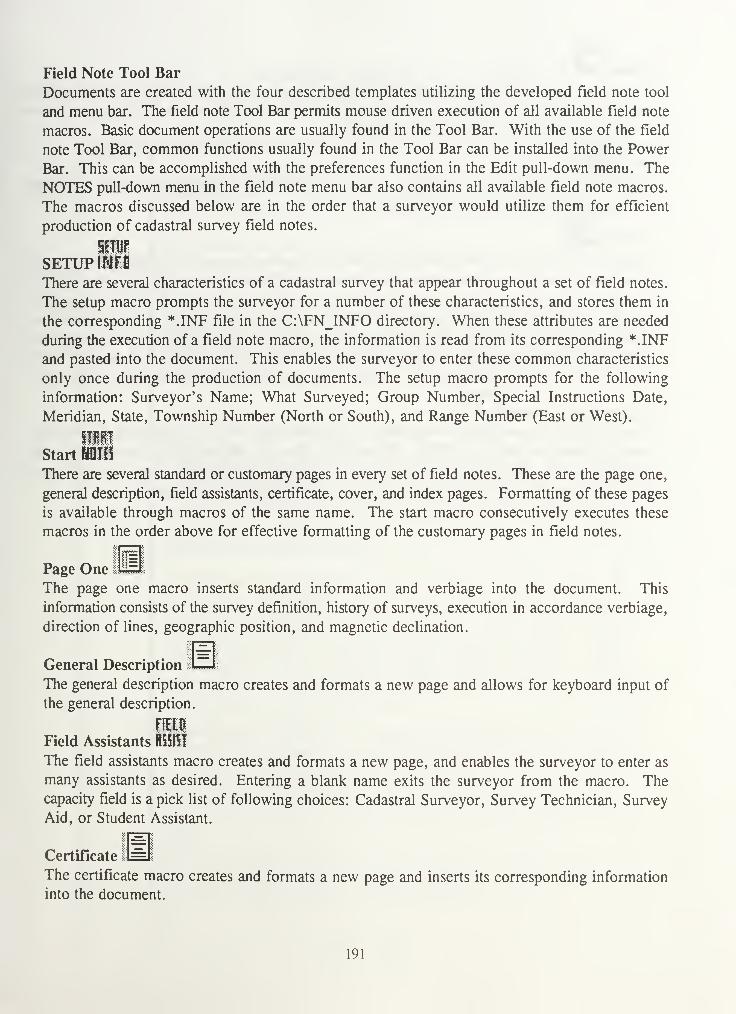
Field Note Tool Bar
Documents are created with the four described templates utilizing the developed field note tool
and menu bar. The field note Tool Bar permits mouse driven execution of all available field note
macros. Basic document operations are usually found in the Tool Bar. With the use of the field
note Tool Bar, common functions usually found in the Tool Bar can be installed into the Power
Bar. This can be accomplished with the preferences function in the Edit pull-down menu. The
NOTES pull-down menu in the field note menu bar also contains all available field note macros.
The macros discussed below are in the order that a surveyor would utilize them for efficient
production of cadastral survey field notes.
SETUPThere are several characteristics of a cadastral survey that appear throughout a set of field notes.
The setup macro prompts the surveyor for a number of these characteristics, and stores them in
the corresponding *.INF file in the C:\FN_INFO directory. When these attributes are needed
during the execution of a field note macro, the information is read from its corresponding *.INF
and pasted into the document. This enables the surveyor to enter these common characteristics
only once during the production of documents. The setup macro prompts for the following
information: Surveyor's Name; What Surveyed; Group Number, Special Instructions Date,
Meridian, State, Township Number (North or South), and Range Number (East or West).
SillStart III!
There are several standard or customary pages in every set of field notes. These are the page one,
general description, field assistants, certificate, cover, and index pages. Formatting of these pages
is available through macros of the same name. The start macro consecutively executes these
macros in the order above for effective formatting of the customary pages in field notes.
Page OneThe page one macro inserts standard information and verbiage into the document. This
information consists of the survey definition, history of surveys, execution in accordance verbiage,
direction of lines, geographic position, and magnetic declination.
General Description
The general description macro creates and formats a new page and allows for keyboard input of
the general description.
Field Assistants RiSIO
The field assistants macro creates and formats a new page, and enables the surveyor to enter as
many assistants as desired. Entering a blank name exits the surveyor from the macro. Thecapacity field is a pick list of following choices: Cadastral Surveyor, Survey Technician, Survey
Aid, or Student Assistant.
Certificate 1
The certificate macro creates and formats a new page and inserts its corresponding information
into the document.
191

cover lyy*
The cover page macro also creates and formats a new page, and inserts its corresponding
information into the document. Because of the necessary centering on the page, the macro
provides keyboard entry of the survey heading.
Index
The index macro creates a new page and formats the heading information. It then inserts the
rectangular index chart into the document.
iiili
CSTUFTOThe surveyor now has a document with the common or standard pages in field notes built through
the setup and start macros. He or she is now ready to enter the field note (.fn) file from CSTUF.The CSTUF macro inserts the defined field note (.fn) file into the document at the cursor location.
It then formats the bearings, distances, accessories, and verbiage found. The * Point No.
^Station verbiage is left in the document because it is usually very beneficial in a reviewing sense
to have the station names next to their descriptions. The Remove * Point ID's function in the
NOTES pull-down menu removes this verbiage when ready for a final version of the field notes.
Cap Remark Format
The last step in formatting the field note (.fn) file from CSTUF is converting the CAP feature
code or remarks into its corresponding cap marking. The Cap Remark Format macro finds each
CAP feature code, reads it, and then drafts its corresponding cap marking. The following pages
show the results from the setup, start, CSTUF, and cap remark format macros.
192

Dependent resurvey of a Portion
of the Exterior Boundaries, in
Township No. 2 North, Range No. 5 East, of
.....the Fairbanks' s_M AlaskaFEET
| The following field notes are those of the| Dependent Resurvey of a portion of the exterior| boundaries, in Township 2 North, Range 5 East, of1 the Fairbanks' s Meridian, in the State of Alaska.
1
I The history of previous surveys are as follows:
I
| History of Surveys Entered Here!I
| The survey was executed in accordance with theI specifications set forth in the Manual ofI Surveying Instructions, 1973 , and the Special
IInstructions for Group No. 99, Alaska dated
j December 25, 1996.
| Preliminary to the resurvey the lines of theI original survey were retraced and a search was| made for all corners and other calls of record.| Identified corners were remonumented in their| original positions; lost corners were restored and| monumented at proportionate positions based on theI original record. The retracement data wereft!
-*
| thoroughly verified and only the true line field| notes are given herein.
i
I The direction of the lines of this survey refer to| the true meridian, and were determined by hourI angle observations of the sun. The lines were| carried forward by sustained angulation being| supplemented by other solar observations taken| throughout the progress of the survey. The| measurements of these lines were made with an1 electronic total station.I
| A magnetic marker, which is referred to as a
| "DEEP-1" in these notes, was deposited at the base| of each monument, so indicated. This marker| consist of a magnet, 1 in. Long, 7/8 in. Diam.,I housed in a cellulose acetate tube, 2 5/8 ins.
| Long, 1 in. Diam., with 1 in. Sq. Polyethylene end| caps
.
II
| The geographic position of the S.E. Twp . Cor. AsI determined by GPS, is as follows:I
I
193

Dependent resurvey of a Portion
of the Exterior Boundaries, in
Township No. 2 North, Range No. 5 East, of
the Fairbanks ' s Meridian,, in the State of ALggKA
I FEET Latitude: 66°21'34" N.Longitude: 152°55'21" W. "NAD 27"||
I The mean magnetic declination as determined from1| numerous readings throughout the survey, is 14°
I East
.
1 * Point No. # 400500
I 1
I Point for the sec. cor. of sees. 9 10 15 16 . This| cor. position was established by Steve Kopach,| Statel Registered Land Surveyor No. 1245, in 1990,1 recorded in the Countyl County Courthouse, and is
| accepted as a careful and faithful perpetuation ofI the original cor. position.I
| Monumented by a iron pipe, 2 ins. diam., looselyI set, 4 ins. above ground, with a plastic mkd.1I| At the corner point
|
| Set an stainless steel post, 30 ins. long, 2 H| ins. diam., 26 ins. in the ground, over a
| "DEEP-1", with an steel cap mkd. as shown.
T2N R5ES9 S10
S16 S151997
| From which the new bearing trees
» A cedar, 10 ins. diam., bears N. 43°37' E.23.3 ft. dist., with nail in base, mkd.
A oak, 25 ins. diam., bears N. 53°33' E.19.9 ft. dist., with scribing in base, mkd.BT
| Bury the iron pipe alongside the stainless steel| post.
| From this cor., a power pole no 12345, bears1 S. 40°07' W. 49.4 ft. dist.
194

Dependent resurvey of a Portion
of the Exterior Boundaries, in
Township No. 2 North, Range No. 5 East, of
,,,,,,,J3M("feet
I
.fjftWxW:*:
I Thence, N. 14°55'33" E., bet. sees. 9 and 10.
1 * Point No. # 400540
|l046.46| Point for the E. 1/4 sec. cor. of sees. 10 .This| cor. position was perpetuated by person(s)1 unknown.
|
| From which the original bearing trees
A hickory, 20 ins. diam., bears S. 76°05* W.
31.7 ft. dist., with nothing in base, mkd.
i|Seat a brass tablet, 3 1/4 ins. diam., 3 in. stem
| in drill hole, filled with concrete, flush with| ledge with top mkd. as shown.
AP2
1997
I From which the new bearing trees
A birch, 15 ins. diam., bears N. 11°15' W.61.70 ft. dist., with nail in base, mkd.
A maple, 18 ins. diam., bears N. 47°37' E.11.5 ft. dist., with nail in base, mkd.
| This cor. is located N. 40°04' E. 49.20 ft. dist.,| from power pole
| Thence, N. 58°53'13" E., bet. sees. 9 and 10.
195

Dependent resurvey of a Portionof the Exterior Boundaries, in
Township No. 2 North, Range No. 5 East, of
the Fairbanks^s_^gyxPXMr^Tg State of Alaska
1 * Point No. # 400600S I
I i§
11519.481 Point for the sec. cor. of sees. 3 4 9 10 . This|| cor. position is accepted as having been| established in good faith using proper methods and| procedures .
I FEET
p Monumented by a iron rebar, 1 ins. diam| set, 3 ins. above ground, with no cap
| At the corner point
loosely
| Set an stainless steel sectional rod 40 ins. long,
| 5/8 in. diam., driven 36 ins. in the ground, with1 a "DEEP-1" alongside, with an steel cap mkd.
I
1 MC
S4T2N
S3R5E
1997
From which
A chisel mark in a granite boulder, 5 ft.above ground, bears S. 4°34' W. 16.24 ft.dist., to a cross chiseled in the west face,mkd. B + 0.
* Pen Up Start New Chain* Point No. # Wl
Thence S. 13°52'20" E., 55.87 ft.* Point No. # W2
Thence S. 76°58'21" E., 100.20 ft* Point No. # W3
Thence S. 56 43'43" E., 49.16 ft* Point No. # W4
196

Dependent resurvey of a Portion
of the Exterior Boundaries, in
Township No. 2 North, Range No. 5 East, of
the Fairbanks.^.. Mg of Alaska ^^I FEET
JThence S. 60°42'59 M E., 74.18 ft.
I 1 * Point No. # W5
| General Description
| The land encompassed in this survey is locatedI somewhere in Alaska.
*!
:::::•:«:*:»»»
I 197

United States
Department of the Interior
Bureau of Land Management
FIELD ASSISTANTS
Name Capacity
David R. Roy Cadastral SurveyorTheresa A. Roy Cadastral SurveyorAllen C. Roy Survey TechnicianMichelle A. Roy Survey AidGayle D. Roy Student Assistant
198

CERTIFICATE OF SURVEY
I, Kenneth D. Roy, hereby certify upon honor that, inpursuance of special instructions bearing the date of the 25thday of December, 1996, I have Dependently Resurveyed a Portionof the Exterior Boundaries, in Township 2 North, Range 5 East,of the Fairbanks 's Meridian, in the State of Alaska, which arerepresented in the foregoing field notes as having beenexecuted by me and under my direction; and that said surveyhas been made in strict conformity with said specialinstructions, the Manual of Instructions for the Survey of thePublic Lands of the United States, and in specific mannerdescribed in the foregoing field notes.
Date (Cadastral Surveyor)
CERTIFICATE OF APPROVAL
BUREAU OF LAND MANAGEMENTSpringfield, Virginia
The foregoing field notes of the Dependent Resurvey of a
portion of the exterior boundaries, in Township 2 North, Range5 East, Fairbanks' s Meridian, Alaska, executed by Kenneth D.
Roy having been critically examined and found correct, arehereby approved.
Date (Chief Cadastral Surveyor, Eastern States)
199

United States
Department of the Interior
Bureau of Land Management
FIELD NOTES
Of the
Dependent Resurvey of a Portion
of the Exterior boundaries of
Township No. 2 North
Range No. 5 East
Of the Fairbanks' s MeridianIn the State of Alaska
EXECUTED BY
Kenneth D. RoyCadastral Surveyor
Under special instructions dated December 25, 1996, approvedDecember 25, 1996, which provided for the surveys includedunder Group Number 99, and authorization/assignmentinstructions dated December 25, 1996.
Survey commenced January 1, 1991Survey completed January 24, 1991
200

INDEX DIAGRAM
Township 2 North, Range 5 East
6 5 4 3 2 1
frnmsmmmssm® wjviwiv: fmfymmmtimimiimiiim :::::::::v:::::::v::
: *:*+&$::$::::#*y.
::::#:
:<
7jj
8 9 10 11
$$%&&&#
12
18 17 16 15 14 13
mmsmmim^mmmimmmA bxflsm fflS;S¥ffi!SSS::
19
jj
20 21 22 23
Uwmw
24
30 29 28 27 26 25
31 32 33 34 35 36
201

Although the example above is small, it illustrates how quickly a rough set of field notes can be
drafted. There are several other developed macros to facilitate common field note operations in
the production of final field notes. They are now listed.
Update Header
The update header macro enables surveyors to update the current header. The update header
macro grabs the text from the existing header allowing the surveyor to edit the text. The updated
text is then inserted in the document between two long lines at the cursor location, and into the
header of the proceeding page.
DistanceMThe distance macro prompts the surveyor for a distance and inserts it in the feet or chains column.
HIDegree Symbol HH I
Inserts the degree (°) symbol in the document at the cursor location.
Long Line L I PuE
Inserts a long line in the document at the cursor location.
Short Line 1111
Inserts a short line in the document at the cursor location.
Rectangular Cap Marking Macros
The following CAP macros draw common rectangular cap markings. They use the *.INF files
in this process. They also solve for remaining section numbers based on the type of cap marking,
and the section numbers which may have been entered. For example, the section cap macro
prompts for the north east section then inserts the remaining corresponding section numbers and
information into the document at the cursor location. The cap marking macros and their matching
icons are East-West Cap BkM , North-South Cap mm , Section Cap '
North Cap mm , South Cap mSm , East Cap mJm , and West Cap
Lat-Long
The lat-long macro prompts for the degrees, minutes, seconds, and datum of the desired latitude
and longitude, and correctly formats and inserts the information into the document at the cursor
location.
5THTI
State Plane MlThe state plane macro is very similar to the
lat-long macro. The state plane macro prompts for X and Y coordinates and inserts that
information into the document at the cursor location. It then prompts the surveyor to define howthe coordinates were derived and inserts that verbiage into the document.
202

Certificate of Transcript isThe Certificate of Transcript usually is located on the certificate page in the duplicate set of field
notes. The certificate of transcript macro inserts its verbiage into the document at the cursor
location.
Missouri State Plane %GkThe Missouri state plane macro is only used with the corner recordation template. The State of
Missouri requires state plane coordinate listings on the bottom of all corner recordation sheets.
The Missouri State Plane macro calls the state plane macro, and then formats the information at
the bottom of the current page.
SummaryThe effort involved in the generation and review process of final plats and field notes of cadastral
surveys has long been a time consuming, tedious, and error prone portion of the "Field to Finish"
process. This thesis has provided the tools and procedures for effective collection and
manipulation of descriptive and numerical observations into plats and field notes.
CEFB now provides several tools and functions for the practical initial (pre boundary analysis)
collection of survey data through the index file, as well as the capabilities of collection of
descriptive and linework information (post boundary analysis) for the production of plat and field
notes through feature codes and chain collection. There are also several other enhancements in
CEFB that have increased the efficiency of day to day survey operations.
The DXF program now provides the ability to read CEFB chain and observation files for
automatic production of linework and symbology in AUTOCAD. The CSTUF program provides
capabilities for rounding, sorting, editing, and structuring of descriptive and numerical survey data
to be brought into word processing software (WordPerfect). The field note macros and templates
in WordPerfect provide the final steps of formatting descriptions, accessories, bearings, distances,
headers, and cap markings.
These procedures will reduce the amount of time required for office production and review of
cadastral surveys. With collected linework and descriptions from the cadastral surveyors in the
field, reviewers can quickly produce rough draft plats and field notes without typing a
description, distance, or bearing in WordPerfect, and plats without drawing a line in AUTOCAD.
These procedures, however, will never produce final versions of plat and field notes. Each survey
is unique in that it has its own special characteristics that cannot be automated. These procedures
do, however, provide the basic foundation for the effective production of rough draft plats and
field notes. Small amounts of editing can convert these items to final form.
203

The most important concept in this process is that the production of plats and field notes starts in
CEFB. Tailored feature code and index files are crucial for the efficient production of field notes
and plats. Cadastral surveyors must use these files in the field to write their field notes and
produce linework for plats. Collection of this information in digital form in the field eliminates
a time consuming part of the way field notes and plats have been produced in the past. Surveyors
can complete corner descriptions, and collect the linework of the boundary in a chain, as they
observe the information in the field. The time spent collecting this information in the field will
greatly reduce the time spent producing these products in the office.
204

APPENDIX A - Instrument setup
Lietz Older Total Stations
Models:
SET2, SET2A, SET3, SET3A, SET4-4A
These older Lietz/Sokkia total stations do not allow a remote field computer to control the
instrument measurement mode, but they do dump data. For one of the more recent types see the
next entry for Lietz/SOKKIA Newer total stations. For these older total stations the operator must
key the instrument for each measurement and set the modes (HV) or distance, manually in the
process. If desired the user can also zero the plates on the back sight, but this is not mandatory.
These instruments communicate at 1200 baud. If you make the Lietz SET 234/a selection from
the CEFB Instrument menu, you must set your instrument communications parameters to 1200
Baud. On many of these instruments, this is not an option and is preset. Thus try it first, then
if doesn't work see if there is an option to set the serial port speed.
The instrument operator must place the instrument in the correct measurement mode for the proper
data to be transmitted. The mode the instrument needs to be set at the instrument keyboard,
corresponding to the type of data CEFB is trying to gather.
When polling the instrument with CEFB the operator will be prompted to hit either the:
[CA][th] keys, or the
[CA] [slope] keys.
The [th] theodolite key refers to a key which usually has a theodolite graphic on it. This will
cause the plates to be read and the data ready for CEFB. The operator then hits any key on the
CEFB machine to clear the prompt window and the data will be accepted. This prompt occurs
on the back sight and at any other time while in HV mode. When at the back sight the operator
may also SET to zero the plate before hitting the [CA][th] key combination.
The [slope] theodolite key refers to a key which indicates slope distance by the top of a triangle
graphic. This selection will then cause the plates to be read and a distance measurement to begin.
At any time the operator can then hit any key on the CEFB machine to clear the prompt windowand the data will be accepted when the distance is taken, providing the instrument timeout period
has not elapsed. You can also elect to wait until a distance has been read before hitting the key
on CEFB. This prompt occurs at any foresight in HVD mode. There is no distinction madebetween fine and course mode on CEFB with this instrument selection.
205

Lietz/Sokkia Newer Total Stations
Models: SET2B, SET2C, SET3B, SET3C, SET4B, SET4C
These newer Lietz/Sokkia total stations allow full remote control by CEFB. To use an older
instrument see LIETZ, above. For these newer instruments Select SOKKIA SET 234/bc from the
instrument selection menu.
The CEFB interface must be properly set for RS-232 communications to take place. Follow
manufacturer's documentation for setting the communications protocol to 2400 baud, No parity,
and 1 Stop Bit. It is optional if you would like to invoke the checksum, although it is not
necessary.
Pentax Total Stations
Models: PTS-10, PTS-II series, also PTS-III
Pentax total stations do not allow a remote field computer to control the instrument measurement
mode. The total station can however, be instructed to begin the measurement cycle and transmit
the data by CEFB once the measurement mode is selected from the instrument keyboard. The
instrument operator will select between theodolite mode, for HV observations, or total station
mode for HVD observations.
The instrument operator must place the instrument in the correct measurement mode for the proper
data to be transmitted. The mode the instrument needs to be set at the instrument keyboard,
corresponding to the type of data CEFB is trying to gather.
To place the instrument in theodolite mode (H, HV Observations):
1) Instrument must be on
2) Press the V/H [7] key, to place the instrument into angle measurement mode
To make a measurement with CEFB:
1) Press the POLL function key on the field computer
To place the instrument in total station mode (HVD, HD, VD, D Observations):
1) Instrument must be on
2) Press the SLP/V [5] key to place the instrument into an angle/distance measurement
mode
To make a measurement with CEFB:
1) Press the POLL function key on the field computer
Note: Make sure instrument is set for Zenith at degrees.
The instrument will automatically go into an AIM MODE, and will cycle until the EDMstabilizes. When the EDM stabilizes, the data is then transmitted to the field computer.
206

The PTS-III instruments can also be used by proper switch settings. These are to set all the
switches on the 3rd row are set OFF with the exception of switch 5, which should be on. You
have to be sure to set the gun to HV mode each time you turn it on.
Topcon Total Stations
Models: GTS-3B, GTS-3C, GTS-4
Topcon Total stations allow fully automatic control of instrument measurement mode by FIELDPACK. A BCC data checking system is employed to insure the integrity of the transmitted data.
To set the instrument serial port for use, the following one-time-only procedure must be followed
the first time the instrument is to be used with the field computer. It is NOT necessary to perform
this procedure again, unless the user has changed the settings that this procedure has implemented.
Setting up Topcon GTS-3B
1) Turn on the power switch while pressing the
[R/L] key continuously for about 1 second
2) Rotate the telescope to make zero-setting
3) Press the [lightbulb] key
4) Press the [V/H] key twice
5) Press the [R/L] key
6) Press the [0 SET] key
7) Press the [V/H] key twice
8) Press the [0 SET] key
9) Turn the power off
DISPLAY
SET "
FAC.XX.XX00"
12.00.00"
12.00.01"
12.01.01"
14"
14 SET "*See Notes
The previous procedure is performed to change the mode "12. 00.XX" to "12. 01.XX".
Notes: * If the display was " 14 E99 ", turn off the power and repeat the procedure from step 1.
* When the GTS-3B is used with the TOPCON Data Collector FC-1/2 or Data Entry
Keyboard DK-5, The above procedure EXCEPT step 5) must be repeated to restore the
original condition of the instrument to "12.00.00".
In the case of the second note, step 4) and 6) will differ from the above as follows:
207

Action for Topcon GTS-3B
1) Turn on the power switch while pressing the
[R/L] key continuously for about 1 second
2) Rotate the telescope to make zero-setting
3) Press the [lightbulb] key
4) Press the [V/H] key twice
5) Omit this step
6) Press the [0 SET] key
7) Press the [V/H] key twice
8) Press the [0 SET] key
9) Turn the power off
DISPLAY
" SET "
" FAC.XX.XX "
" 00"
" 12.01.00"
" 12.01.00"
" 14 SET "
Note: Make sure the DIP switch in the RS-232 Port is set to NO ECHO. This is accomplished
by removing the four screws and pulling out the port cover, which pulls the attached board
out. A bank of two dip switches are found on the board and should be set to switch 1 ON,switch 2 OFF.
Setting up Topcon ET-2
1) Turn on the power switch while pressing the
meter/feet selector switch continuously until
buzzer sound is stopped. The display will be
blank except the meter/feet and the degree/grad
unit.
2) Operate the [V/H] switch, instrument will
a flashing first digit (right)will be
displayed if it is not changed before
3) Move a flashing digit to the 2nd digit.
A flashing digit can be shifted each time by
operating the [V/H] switch.
4) Operate the [REC] switch, the 2nd digit will
be changed to a " 1
"
5) Operate the [F] switch. Nothing but the
meter/feet and the degree/grad unit will be
displayed, indicating the setting is complete.
6) Turn the power off.
Note: When the ET-2 is used with the TOPCON Data Collector FC-1/2 or Data Entry Keyboard
DK-5, The above procedure must be repeated with the exception described below to get
the original condition of the instrument
DISPLAY
" FAC 10.10"H ii
" 00000000"
" 00000000"
" 00000010"
208

Action for Topcon ET-2
1) Turn on the power switch while pressing the
meter/feet selector switch continuously until
buzzer sound is stopped. The display will be
blank except the meter/feet and the degree/grad
unit.
Operate the [V/H] switch
Move a flashing digit to the 2nd digit.
A flashing digit can be shifted each time by
operating the [V/H] switch.
Operate the [REC] switch, the 2nd digit will
be changed to a "0"
Operate the [F] switch. Nothing but the
meter/feet and the degree/grad unit will be
displayed, indicating the setting is complete.
6) Turn the power off.
2)
3)
4)
5)
Display
" FAC 10.10"
I ii
" 00000010 "
" 00000010 "
" 00000000 "
Setting up Topcon GTS-4This procedure is used to add the ASCII characters CRLF to the end of the data output strings for
connection to a computer.
1) Turn on the power switch while pressing the [2] key continuously for about 1 second.
DISPLAY[PARAMETERS MENU]
2) The parameters menu is displayed
3) Press the [3] Key
4) Press the [F4] Key
PARAMETERS \1 : ANGLE2:DIST3 : DATA-OUT
DATA-OUT h
CRLF: OFF
SET ITEM—SLCT
r
DATA-OUT hCRLF: ON
SET ITEM—SLCT
209

5) PRESS the [Fl] Key r
DATA-OUT
<SET!>
6) Display is returned to the Parameters menu
7) Turn off the power
To make a measurement with CEFB:
1) Press the POLL function key on the field computer
Setting up Topcon GTS300 Series
The GTS300 Series of instruments has been successfully used with CEFB with proper
configuration of the instrument. Consult the Instrument Manual to see how to access the MODEsettings.
MODE SETTINGS FOR TOPCON 300 SERIES:
Mode three is the data collection mode. It contains 8 digits which read from RIGHT TO LEFT.These should be set as follows:
1=0, 2=1, 3=0, 4 = 1, 5=0 6 through 8 are not used and should be set to 0.
The other MODE settings (1 and 2) are for manual use and should be set accordingly for that use.
Wild Total Stations
Models: T(C)1000, T1010
Need to Place Jerry's Doc's concerning the instrument setup for the wild instruments.
Pentax Total Stations
Need Something here !!!!!
210

APPENDIX B - Hewlett Packard Data Transfer
Hewlett Packard - Connectivity Pack
This section contains a brief explanation of the installation procedure for the HP Connectivity
Pack, followed by an explanation of the file transfer program. If any problems are encountered,
refer to the 'Connectivity Pack User's Guide'.
Installation
1. Insert disk 1 included with the Connectivity Pack into the appropriate size disk drive
(usually drive A).
2. type: a: < Enter > (or the appropriate disk drive letter) install < Enter >3. Follow the predefined answers as installation occurs.
4. When installation is complete, remove the disk and reboot the computer. This can be done
by pressing the <Ctrl> < Alt> <Del> keys all at once, or by turning the computer off
and then on.
Check the autoexec.bat file
1. At the DOS prompt type: set < Enter >2. Look after PATH to see if the Connectivity Pack directory is included in the string. For
example, C:\CPACK should exist if installation to the C drive was made. If the directory
exists in the path, you are done, otherwise continue with step 3.
3. If the C:\CPACK (or appropriate directory) does not exist in the path, use a text editor to
add it to the autoexec.bat file, then reboot the PC. This will allow you to start the file
transfer program from the DOS prompt. If you do not wish to edit the autoexec.bat file,
you can still use the file transfer program by changing to the c:\cpack directory before
activating the program.
Setting the HP for the Filer
1. Start the filer on the HP by pressing the blue Filer key. It is located just below the
<Esc> key.
2. Press the <Menu> key.
3. Press the letter R for Remote-Set.
4. Press the letter C for Configuration.
5. Press the letter / for Interface.
6. Press < Enter > to select 1 (Coml).
7. Press B to select Baud.
8. Press the number 6 to select 6 (19200).
9. Press Q to quit.
10. Optional: Press 5 to save these settings to a file. At the C:\_Dat\*.FCF prompt, type any
filename and press < Enter > .
1 1
.
Press Q to quit the Filer Menu.
211

Setting the PC for the Filer
1. Connect the PC and the HP95 using the serial cable. This cable will have one end with
a small 4 pin connector for the HP95, and a nine or twenty five pin connector for the PC.
If you have any questions, see pages 1-4 and 1-5 in the Connectivity Pack User's Guide.
2. On the HP, Open the Filer as you did in step 1 during the HP95 Setup.
3. On the PC type: app <HP Model> < Enter > . This will start the APP program. If the
program did not start from the DOS prompt, try logging to the C:\cpack directory and
repeat this step.
4. Simultaneously press the < Alt> key and the number 2 to start the Filer application.
5. Simultaneously press < Alt> - <F10> , then /?, and finally C to view the Filer remote
settings.
6. Make sure the Interface settings match the serial port being used on the PC. Generally,
COM1 is the nine pin serial port that connects the mouse to the PC. If your not sure, try
several combinations. To change the COM port press the letter / and then select the
proper COM port by pressing the corresponding number 1-4.
7. Make sure the Baud setting is set to 19200. To change it, press the letter B, then select
the baud rate by pressing the corresponding number 1-7.
8. Press the Q twice to quit the remote settings and display the current directory.
Transferring Files
1. On the HP95, open the Filer Menu. This is the only step performed on the HP.
2. On the PC, type: app <HP Model> < Enter > from the DOS prompt to start the APPprogram.
3. Simultaneously press < Alt> and the number 2 to start the Filer application.
4. Press <F7> Split, then <F6> Remote to split the screen and establish a remote
connection. The display on the PC will show a local (PC) directory and a remote (HP95)
directory similar to Figure B. 1.
212

Note:
Filer 02/24/93 9:49 pmRemote NoDirs Local
C:\ C:\dat ;
:<DIR> AAA <DIR>
CHKDSK EXE AERO <DIR>COMMAND COM CPACK <DIR>TF COM DOS <DIR>CARLOAN WK1 HYPER <DIR>CFLOW WK1 JF <DIR>EXPENSE WK1 NORTON <DIR>HOMEBUY WK1 PCTOOLS <DIR>
_STAT WK1 WP51 <DIR>
Copy Local Ren arae MoveHelp Delete Goto Full Tag
Fl F2 F3 F4 F5 F6 F7 F8 F9 F10
Figure B. 1: Remote and Local File Windows on the PC
Display the destination directory. This is the directory that you wish a file to go into.
a. First, use the left or right arrows to toggle between the local (PC) or remote
(HP95) window.
b. Second, to change to the desired directory, press <F5 > GOTO, and then enter
the directory name, or highlight the directory name and press < Enter >
.
If you are going to transfer a field file to the CMM directory on the PC, first make sure
that you are on the Local (right) side of the screen. If the CMM directory is on the Cdrive, just highlight the directory and press < Enter > . The third line of the screen will
update to C:\CMM. If your CMM directory is on another drive, press <F5>, type
(drive letter):, and press < Enter> . Now you may highlight the CMM directory and press
< Enter >.
6.
Note:
7.
8.
9.
10.
Display the source directory. This is the directory which contains the file that you wish
to transfer. Steps a & b above apply here also.
To change to the CEFB directory on the A drive of the HP95, make sure that you are on
the Remote (left) side of the screen. Press < F5 > , and then type a: < Enter > to display
the directories on the A drive. Now highlight the CEFB directory, and press < Enter >to display the list of files..
Highlight the file to be transferred.
Transfer the file by pressing <F2 > , and then < Enter >
.
When finished transferring the file, simultaneously press < Alt> - <F6> to break the
remote connection.
Press MENU by pressing < Alt > <F10> and then Q to quit.
213

11. Simultaneously press < Alt> and to exit the APP95 program. Use the zero above the
letters, not the zero on the keypad.
12. On the HP95, select the Menu button and quit. If you are not using an AC adapter,
unplug the serial cable to preserve battery line.
If you wish to transfer more than one file at a time, see page 2-5 of the Connectivity Pack User's
Guide.
Data File Transfer using ProComm Plus
This is just one of several methods to accomplish data file transfers.
Setting up the PC1. Run PCPLUS.2. Once in PCPLUS press ALT P and set the following parameters:
Baud Rate = 19200, Parity = None, Data Bits = 8, Stop Bits = 1, Port = COM 1
3.. Once you complete these settings press ALT S to save. This will save these settings in the
CMM directory so whenever you call up PCPLUS in that directory you will be all set to
transfer.
Setting up the HP1. From the opening screen press the "BLUE" COMM key. These key functions are only
available from the opening screen. If you have shelled to DOS or are in some other
program they will not be active and you must completely exit back to the opening screen.
2. After pressing the "BLUE" COMM key the display reads; Datacomm and the current date
and time at the top of the screen with the rest of the screen blank.
3. Press the "WHITE" MENU key, bottom row, 2 keys left of the key. A new menu will
appear at the top with Settings highlighted.
4. Press enter to select the highlighted Settings choice.
5. A new menu will appear. Select Config. This can be done by cursoring to the Config or
simply hitting C, a new menu will appear.
6. This is the configuration menu for the communications setup. The HP must be set up
exactly the same as the PC. Set up is as follows:
a. Highlight Port and hit enter, a new menu appears at the top of the screen.
Highlight Interface and enter. Highlight 1 <Coml> and enter. You will be
returned to the previous menu.
b. Highlight Port again and enter. Highlight Baud and enter. Highlight 6 < 19200 >and enter.
214

c. Highlight Port again and enter. Highlight Stop and enter. Highlight 1 and enter.
d. Highlight Port and enter. Highlight Parity and enter. Highlight None and enter.
e. Highlight Port and enter. Highlight Char and enter. Highlight 8 and enter.
f. Now highlight Terminal and enter (You can skip Dial). Highlight Emulation and
enter. Highlight None and enter.
g. Highlight Terminal and enter. Highlight Wrap and enter. Highlight Disable and
enter.
h. Highlight Terminal and enter. Highlight Backspace and enter. Highlight
Backspace and enter.
I. Highlight Other and enter. Highlight Echo and enter. Highlight Disable and
enter,
j. Highlight Other and enter. Highlight flow and enter. Highlight None and enter.
k. Highlight Other and enter. Highlight Duplex and enter. Highlight Full and enter.
1. Highlight Capture and enter. Highlight None and enter.
m. Skip X-late and Script. These are not needed and should be blank on the setup
screen,
n. Highlight Quit and enter. A new menu will appear, highlight Save and enter. Anew screen will appear asking where you want to save the setup stuff. If you
simply enter it will be saved to the C:\DAT\ directory as DEFAULT.DCF which
is what you want to do, so hit enter. If you get a message: Overwrite existing file?
< Y/N > type in Y and enter.
o. You are now finished setting up the HP. Highlight Quit and enter. Press the
"WHITE" MENU key now. Highlight Quit and enter. You will be returned to the
opening screen. The setup just created will not need to be done again unless you
change something.
Transferring Files
1. Connect the PC to the HP-95 with the serial interface cable, be sure to use COMM 1 on
the PC, usually the same port as the mouse uses.
2. On the PC, go to the CMM directory and run PCPLUS by typing the full path to do this,
ie. C:\PCPLUS.
3. Press pageup (PgUp) (UpLoad a file) on the PC to upload a file to the HP-95. You will
see a Protocol menu, select KERMIT (No. 2). A menu will appear asking for the file
name to be transferred. Type in < Filename > , DO NOT HIT ENTER YET.4. On the HP, from the opening screen, press the "BLUE" COMM key. Then press the
"WHITE" MENU key. If you want to verify the set up stuff, highlight settings and enter,
read the settings to see if they are correct. If OK, highlight Quit and enter, if not you will
need to set them as above or highlight USE and enter. This will bring up the settings that
were saved in the setup process we did above, then press enter to use those saved settings.
Now highlight Quit and press enter.
5. Now press the "WHITE" MENU key. Highlight Transfer and enter. Highlight Kermit
and enter. Highlight Options and enter. Highlight File and enter. Highlight Binary and
press enter.
6. Highlight RECEIVE and press enter.
215

7. A new menu will appear with a flashing cursor. Type in the file name and path on the HPthat you are transferring.
8. Now hit enter on the HP and immediately enter on the PC. If all was done correctly the
file should begin transfer to the HP. If something goes astray, follow the menu selections
and abort the transfer. Check all setup stuff and try again.
Xmodem protocol always transfers full 128 byte records. So, if your file is not an exact multiple
of 128 bytes in length, which it almost always is not, XMODEM will add bytes onto the end of
the file. This can cause FFTOOBS to indicate an invalid record type, but usually the OBS file is
okay. KERMIT protocol is much faster than XMODEM to transfer. The key to all this is the
pageup (PgDn) and pagedown (PgDn) on the PC.
To pass a file from the HP to the PC the steps a very similar. On the HP, from the opening
screen, press the "BLUE" COMM key, then the "WHITE" MENU key. If all the settings are OKhighlight transfer and enter. Highlight kermit and enter. Highlight Options and enter. Highlight
file and enter. Highlight Binary and enter. Highlight Send and enter. At this point you are
presented with a menu of the C:\*.* directory. Highlight the file you want to transfer and enter.
On the PC, run PCPLUS from the CMM directory as before. Select the pagedown (PgDn) key
(Down Load a file) and select KERMIT from the protocol menu. The file will begin to transfer
at this time.
216

APPENDIX C - Observation and Chain File for DXF Program
Abbreviated Observation File
RCEFB v 1.0006 Hunit= ft Vunit= ft
R MH1 MANHOLE: Manhole
R MH2 MANHOLE: Manhole
R TREE1 TREE: A ash, 12 ins. diam.
R MB1 MAIL_BOX: Mail box
R LTP1 LIGHT_POLE: Light pole
R FHY1 FIRE_HY: Fire hydrant
R PIPE1 PIPE: Pipe
R P2 PILE: Pile
S 1 2
B 0.0
F Bl
F B2
F B3
F B4
F B5
F B6
F B7
F B8
F B9
F B10
F Bll
F B12
F B13
F B14
F B15
F B16
F CRK1F CRK2F CRK3F CRK4F CRK5F CRK6F CRK7F CRK8F FNC1F FNC2F FNC4F FNC5F FNC6F FNC7F FNC8
217

F FNC9F FNC10F MH1F MH2F FHY1F LTP1F MB1F TREE1
Chain File
BUILDING No #1: building owned by FREDBUILDING No #2: house owned by TOMBUILDING No #3: garage owned by Ray
BUILDING No #4: shed owned by Hans
BUILDING S Bl B2 B3 B4 Bl B5 B6 B7 B8 B5 B9 BIO Bll B12 B9 B13 B14 B15 B16 B13
CREEK C CRK1 CRK2 CRK3 CRK4 CRK5 CRK6 CRK7 CRK8FENCE S FNC1 FNC2 FNC3 FNC4 FNC5 FNC6 C FNC7 FNC8 FNC9
218

APPENDIX D - Observation Files with Recorded Feature Codes
File OneR CEFB v 12/06/96 Hunit= ft Vunit= ft
R 400500 POINT_FOR: Point for the sec. cor. of sees. 9 10 15 16 ._This_cor. position
was_established by Steve Kopach, Statel Registered Land Surveyor No. 1245, in 1990, recorded
in the County 1 County Courthouse, and is accepted as a careful and faithful perpetuation of the
original cor. position.
R 400500 MON_FD: Monumented by a iron pipe, 2 ins. diam., loosely set, 4 ins. above ground,
with a_plastic mkd.
R 400500 AT: At the corner point
R 400500 MON_SET: Set an stainless_steel post, 30 ins. long, 2 xh ins. diam., 26 ins. in the
ground, over a "DEEP-1", with_an steel cap mkd. as shown.
R 400500 CAP: CAP rectangular_marking interior standard 4_sections -f- S10 S15 S16 S9 1997
R 400500 FROM_WHICH: From which the_new bearing trees 2trees A cedar, 10 ins. diam.,
bearsA(400500 BT1) N. 44°56'16" E. 2308.81 ft. dist. , with nail in base, mkd. TREE A oak,
25 ins. diam., bears '(400500 BT2) N. 54 52, 42" E. 1962.42 ft. dist. , with scribing in base,
mkd. BTR 400500 BURY: Bury the iron_pipe alongside the stainless_steel post.
R 400500 FROM_THIS: From this cor., a power pole no 12345, bearsA(400500 POLE1) S.
41°51 , 33" W. 498842.97 ft. dist.
R 400540 POINT_FOR: Point for the E. 1/4 sec. cor. of sees. 10 ._This_cor. position
was_perpetuated by_person(s)_unknown.
R 400540 MON_SET: Seat a brass tablet, 3 1/4 ins. diam., 3 in. stem in drill hole, filled with
concrete, flush with ledge with top mkd. as shown.
R 400540 CAP: CAP angle_point_marking Lines From Center: 2A(400540 400500) S.
16o 15'08" W.
A(400540 400600) N. 60°12 ,
41HE. 1997
219

File TwoR CEFBv 12/06/96 Hunit= ft Vunit= ft
R 400540 THIS_COR.: This cor. is locatedA
(P0LE1 400540) N. 40o55'10 u
E. 499786.64 ft.
dist. , from power pole
R 400540 FROM_WHICH_FD: From which the_original bearing trees TREE A hickory, 20 ins.
diam., bears '(400540 BT3) S. 77°25 , 01" W. 381.66 ft. dist. , with nothing in base, mkd.
R 400540 FROM_WHICH: From which the_new bearing trees 2trees A birch, 15 ins. diam.,
bearsA(400540 BT4) N. 9°55'07" W. 617.57 ft. dist. , with nail in base, mkd. TREE A maple,
18 ins. diam., bearsA(400540 BT5) N. 48°56'17" E. 1123.34 ft. dist. , with nail in base, mkd.
R 400600 MON_FD: Monumented by a iron rebar, 1 ins. diam., loosely set, 3 ins. above ground,
with no_cap
R 400600 AT: At the corner point
R 400600 MONSET: Set an stainless_steel sectional_rod 40 ins. long, 5/8 in. diam., driven 36
ins. in the ground, with a "DEEP-1" alongside, with_an steel cap mkd.
R 400600 CAP: CAP rectangularjnarking interior meander =p S3 S4 *(BT1 BT5) N. 77°35'34"
W. 1997
R 400600 POINT_FOR: Point for the sec. cor. of sees. 3 4 9 10 ._This_cor. position is_accepted
as_having_been established in good faith using proper methods and procedures.
R 400600 FROM_WHICH: From which chisel A chisel mark in a granite boulder, 5 ft. above
ground, bearsA(400600 BT6) S. 5 53'48" W. 1642.87 ft. dist. , to a cross chiseled in the west
face, mkd. B + O.
220

APPENDIX E - Resulting Remark (.rem) File from MakeRem Function in CSTUF
* Point No. # 400500
POINT_FOR: Point for the sec. cor. of sees. 9 10 15 16 . This cor. position was established by
Steve Kopach, Statel Registered Land Surveyor No. 1245, in 1990, recorded in the Countyl
County Courthouse, and is accepted as a careful and faithful perpetuation of the original cor.
position.
MON_FD: Monumented by a iron pipe, 2 ins. diam., loosely set, 4 ins. above ground, with a
plastic mkd.
AT: At the corner point
MON_SET: Set an stainless steel post, 30 ins. long, 2 xh ins. diam., 26 ins. in the ground, over
a "DEEP-1", with an steel cap mkd. as shown.
CAP: CAP rectangular marking interior standard 4 sections -f- S10 S15 S16 S9 1997
FROM_WHICH: From which the new bearing trees 2trees A cedar, 10 ins. diam., bears
N.$43°37'$E. 23.3$ft. dist., with nail in base, mkd. TREE A oak, 25 ins. diam., bears
N.$53°33'$E. 19.9$ft. dist., with scribing in base, mkd. BTBURY: Bury the iron pipe alongside the stainless steel post.
FROMTHIS: From this cor., a power pole no 12345, bears S.$40°07'$W. 49.4$ft. dist.
* Point No. # 400540
POINT_FOR: Point for the E. 1/4 sec. cor. of sees. 10 . This cor. position was perpetuated by
person(s) unknown.
FROM_WHICH_FD: From which the original bearing trees TREE A hickory, 20 ins. diam.,
bears S.$76°05'$W. 31.7$ft. dist., with nothing in base, mkd.
MON_SET: Seat a brass tablet, 3 1/4 ins. diam., 3 in. stem in drill hole, filled with concrete,
flush with ledge with top mkd. as shown.
CAP: CAP angle point marking Lines From Center: 2 165° 58° AP2 1997
FROM_WHICH: From which the new bearing trees 2trees A birch, 15 ins. diam., bears
N.$iri5'$W. 61.7$ft. dist., with nail in base, mkd. TREE A maple, 18 ins. diam., bears
N.$47°37'$E. 11.6$ft. dist., with nail in base, mkd.
THIS_COR.: This cor. is located N.$40°04*$E. 49.2$ft. dist., from power pole
* Point No. # 400600
POINT_FOR: Point for the sec. cor. of sees. 3 4 9 10 . This cor. position is accepted as having
been established in good faith using proper methods and procedures.
MON_FD: Monumented by a iron rebar, 1 ins. diam., loosely set, 3 ins. above ground, with no
cap
AT: At the corner point
MON_SET: Set an stainless steel sectional rod 40 ins. long, 5/8 in. diam., driven 36 ins. in the
ground, with a "DEEP-1" alongside, with an steel cap mkd.
CAP: CAP rectangular marking interior meander =j= S3 S4 281° 1997
FROM_WHICH: From which chisel A chisel mark in a granite boulder, 5 ft. above ground,
bears S.$4°34'$W. 16.2$ft. dist., to a cross chiseled in the west face, mkd. B + O.
221

APPENDIX F - Resulting Field Note (.fn) File from Field Function in CSTUF
* Point No. # 400500
Point for the sec. cor. of sees. 9 10 15 16 . This cor. position was established by Steve Kopach,
Statel Registered Land Surveyor No. 1245, in 1990, recorded in the Countyl County Courthouse,
and is accepted as a careful and faithful perpetuation of the original cor. position.
Monumented by a iron pipe, 2 ins. diam., loosely set, 4 ins. above ground, with a plastic mkd.
At the corner point
Set an stainless steel post, 30 ins. long, 2 Vi ins. diam., 26 ins. in the ground, over a "DEEP-1",
with an steel cap mkd. as shown.
CAP rectangular marking interior standard 4 sections —|— S10 S15 S16 S9 1997
From which the new bearing trees
* IndentA cedar, 10 ins. diam., bears N.$43°37'$E. 23.3$ft. dist., with nail in base, mkd.
* IndentA oak, 25 ins. diam., bears N.$53°33'$E. 19.9$ft. dist., with scribing in base,
mkd. BT
Bury the iron pipe alongside the stainless steel post.
From this cor., a power pole no 12345, bears S.$40°07'$W. 49.4$ft. dist.
* Brg N. \A°55"iy' E., bet. sees. 9 and 10.
* Dist 1046.46
* Point No. # 400540
Point for the E. 1/4 sec. cor. of sees. 10 . This cor. position was perpetuated by person(s)
unknown.
From which the original bearing trees
* IndentA hickory, 20 ins. diam., bears S.$76°05'$W. 31.7$ft. dist., with nothing in
base, mkd.
Seat a brass tablet, 3 1/4 ins. diam., 3 in. stem in drill hole, filled with concrete, flush with ledge
with top mkd. as shown.
From which the new bearing trees
222

* IndentA birch, 15 ins. diam., bears N.$11°15'$W. 61.7$ft. dist., with nail in base,
mkd.
* IndentA maple, 18 ins. diam., bears N.$47°37'$E. 11.5$ft. dist., with nail in base,
mkd.
This cor. is located N.$40°04'$E. 49.20$ft. dist., from power pole
* Brg N. 58°53'13" E., bet. sees. 9 and 10.
Dist 1519.48
* Point No. # 400600
Point for the sec. cor. of sees. 3 4 9 10. This cor. position is accepted as having been established
in good faith using proper methods and procedures.
Monumented by a iron rebar, 1 ins. diam., loosely set, 3 ins. above ground, with no cap
At the corner point
Set an stainless steel sectional rod 40 ins. long, 5/8 in. diam., driven 36 ins. in the ground, with
a "DEEP-1" alongside, with an steel cap mkd.
CAP rectangular marking interior meander =j= S3 S4 N.$78°55'$W. 1997
From which
* IndentA chisel mark in a granite boulder, 5 ft. above ground, bears S.$4°34'$W.
16.2$ft. dist., to a cross chiseled in the west face, mkd. B + O.
* Pen Up Start New Chain
* Point No. ft Wl
#BrgS. 13°52'20"E., 55.87$ft.
* Point No. # W2
#BrgS. 76°58'21" E., 100.20$ft.
* Point No. # W3
#BrgS. 56 43'43" E., 49.16$ft.
* Point No. # W4
#Brg S. 60o42 , 59" E., 74.18$ft.
* Point No. # W5
223

Q
•awBAaa
V
Q
V
a.
o
u
Is
•a3u
I
1o•a'Vi
&
8a3•Iu•S
>>aoa,
XuV>
1O<u
aoo
sS3
o•oo
E
0-
=*fc
QPQ tt Q=*k tfc tt:

•S
OU
^>
1
d
A«
Q
A
i
V
"SJ3
•J
Ion
g•X3
to
1
Aco•a
1coU1*-
o
V
5 a
fl'h
* v
^ 8
Hj
<u
I A
fl vCm
,!.e
w §
(U He s
8 c
•— cO <D
si
A1
a
v
8c
§«MO
& •aw ak W
V
8c
1) <u
8
•a.Go
.8
"8
•a
A
a
10)
a a.2 8
J <3 •©'
.Si °10)
5

r<
< e * v
•a
Q
ro
Ato JO
5/5 .3 r-,
Co
co
Si
§
1m
mV —QCQ
CO
Ai
QQ<V
>1
C3
.5OX)
•co m
8Si S
T3
I
=3

<U <u
<L>
&
o
u
V
•S
£-.5
co•a
*->
Ai
QQ<V
<*.
two
3IS>t
l ^S3 o•g u
o1
a ei
a *o
s1 ^

o
A
'in'>
A
9 §V V
Ai
Q
V
't/J
oc
l
S%
a
t/1
.a
Ac--ocot-l
Oo
t/5
aV
I3(A
co
ex
2co
3B<u5
9V
dA
QV<uco
I
to
-aaaoa
co
"8
6
5'$
"8
c
aco2
ci
a
Vofco C/5 a
V §. a
.1 -s
a
V V4> CX
? §
£
1 ou
a3oa
3.0
8to
1
oa3oa
0>
ao«,
C/5ou

.siAl
II
|.s,
3260(U
* -9
|.s
n no
«> 2>> P
rt
I
s °
1 <t CO
8..S
1
1
T3as
l
.S
60
i 60I c
o
1)>o3CO
.3
Ac-ac3o1—
a(L>
>O
<COa—
<
V
"3
on 60
8
SI
"8
>>
i-o
1T3, <ua >>
.3 3*
I
5ey
1
co
.3
A
60c
o
V
co
.5
QV
5
wo
36
, ,
exo
CO
3• i—
<
'52.
oc
s,o
•J3
"ex
J3E
s,
co
E»'
s
CO
sX)
—© coB 60
A
a a
•g 53
. exex a8 uE -°3 *Cc oH co
Q2, V
A
V
3
AI
aQ<Vexo
co
.24
4-1
' -1
Ai
Q
V
J2os
ec53
c3O
1
c
c(U
U
ON
#o
c^'O-'
1

A
rx:00
aV
cm
-c00
oo
60
.50000
u
J
.S
>» •
S A
oo Q
Si
3-eo
I!
a) A
II•s.s
*-* . J5
^ v
i
<u
•M
B
§
A
X300
o3
x:oo
aa'
-o03
S,
00
.5 /00 A00 I
° Q
Jv.s'e
le00
1 8 a, §
a3oU
SA
oo-^
o ,-
HOl,
UCL,
g3u
.5
V
A
?00
aV
x:oo
B800
ssoo'
•a00
0)
.s
§*A
oo ya,9
is
a 8
84—
*
3O
o
-o
A
l . v •— 1
A
u
s.il-8
Ai
Q
V
4J
<U>s>-,
S•a3OU
(X(Xjauo£4
x:oo
s
f*
S5 5
to
A
b
VI—
I
ooc3O
03JO
I(L)
e
i
X>
A
co•a
oo
V
ca)
ooo
A
Ooo
V
*.. «
4? §
X200
•13 2i d
a, Ac^-
.3X3oo
o°1
a<->
a 8> tu
i
3a•^
ccOJ
a,
o'
V
C
Av>
.5,
QV
i
303C
cu>•c
Ai
Q
V
-o
J
id
Sa
1
004-1
3o.
oIT00
s1)
c
U

Ai
Q
4)
}a
}
*-»
J5
•J4>
.5
60
5^

2VA
cS,
"8
on
to
8
r/i
zopuOO
V
3
"8
o8
"8
suT3Ou
3
I
U3X)
I
1—
£uua
i-.
8
uo
53
oo
3 £w
1 s.
w
A
ou
Ai
Q
V
A
;tfc
00e-« ZooZo
OP
Fuwu oo
00 VV c/i
O 8
o
Ja
VA
00zOPuwoo
V
uou
s Ia 5
£
53
I
&1
8.•J•9
a'
T3
aUu
ouaS ,2-
I crWD
.3
3
d
o
i—i i
U, Co o
s >^
I
a.
S
aa>uu«
I
.a
co-a'55
Oa,
873
•co<u
•s
co
c
Si<u•a
co
a.I—
I
is•5
i3
•8 5
<u
) „ °
s
I-
s.oa.1
i3
CI

w *c9
s'8
GO «
:> o
A
o
sCO
V
o
co 32
coco"-3
co
sex
COI
CO
CO
zz
I
CO
* A
s5j a4> &
a sb
. oKmJwO CO
o •y to
J- 8cy co
& U
£ 3
a, ^
a"
it
C^>COZOPuwco
V
A
u
Bo
co
V
VA
cozoFuwco
VCO
8ou8
9V
A
gzopuwco
V
CO
(U
;§
c8
5
cO•X3
cot-c
s.s
A*
OPuwco
V
CO
!
I o I
uo
asa
ao

2OBc
I-
O
2
•c
I'
O
on
Oon
E
i——i
uM
<s
1x:
13 w)1?".2 13 &o
e S3i x:
"Si?flJ "St
"8 1«J 'St
ib &
oco•a
80)u+->
CO
At
Q
VQ
x:exE3bO
9
"8
ffl I
u(N
A •»*
9 £v a
Q
5u
2S
T3
m
a
a

V
3'>
Ai
QQ<Vexoco
•5
o
60
.3
A
c32oo
3
V
I3
£3
5
S
Iaao
T3aaoS
"3
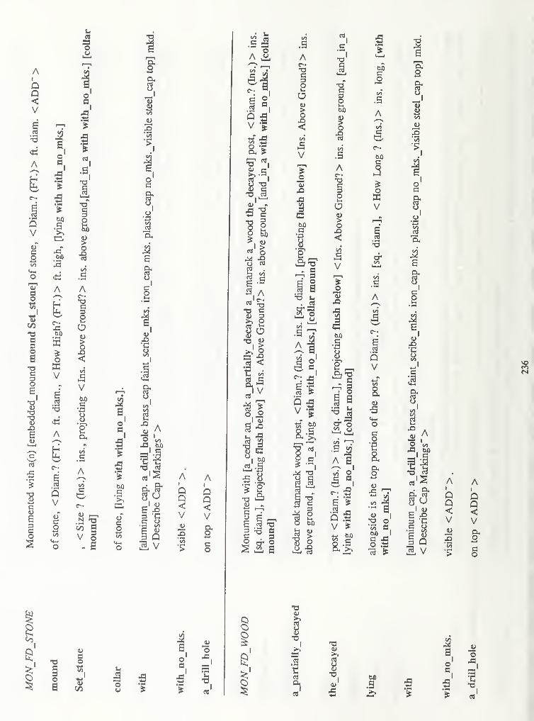
Ai
Q
X)
1/5
.5
-o1
60Co
to
.S
60C
o
V
sr
a3oa
"S
oE
i
"8
•o"8
X>
E
A
3 I60
aoKV
AA
rt
O
t^ o
A60
00
.5
A
QV
on
a0)
S
2gEacos
A
g
1
QV
uco
T3C3Oa
8 -—
'
V §- S
ao
5c/3 1
Ai
QA
i
Q
V V
jo o'55
,-
•s §
8I
60
•o.
-aI>>
4-1
A
VJ£3'55
'£
2co

00
3
pc
c
I6
1>
CO
O13
t
3
a"
oc86
a
73X!
T3
.3
6 A
.s
Iv
9
3s
e3
373
•B'%
j£to
A
00
oWV
SimQ
•3
$•oc3
a5
c/j
.s
Q
V
c>•cQVc53> -o
?1r ex
i s••3 £
A
&
.1 2S-S
i'-f
i—i 4)
* °.
on p
l-H
01
dA
QV
co
oo
co
3
'5
60
.3
A
00
O•zoV
8e3
373a
3oa
.9 73
00
o
T3a3oS
In
-Iou
.3

Ac—
!o
I
1
i
8
I.1-1
I4>
I
!6.
3BO
3 ^o =tfc
2«Ml **
1"
s 1Is- eM OC V-c
'
'
< -S pau J *s
V
A
V
Ar-
8*->to
VA 00c«
§A
V 00
Ai
4-1
1
1V00
HI
h
A
V
A
800
3O00
V00
A
800
o
V00
A
8
V
A
y00*-»
1/5
1)
V00
A
800
A
V
A
i00
6oon
V00
A
800
^ J-
Voo
o2Voo
A
§
V
cU
6fl
iao
so
"8
DOco
aDfl4)
&Ac^-
co\a
00
V00
Ae-
§ 3
uUA
Q
cowV
A
1 5
2 a33OOO
o
c
UA
co3V
ot-
o
VAc-ao
100
o•c<u*->
XwV00
Ac-co\a
00
b -? no•dBaVoo
njrL
Io
i
.2%->ua>
"l
a#oH-f
8Ml
co•a
A
V
n
oOh
(NO
oh
T 3^o
A
800H-lV)1)
V00
A
800
V00
A
oOhv©
A
oo
53o00
V00
A
800
o
V00
A
IV
nu00
A
8004-1t/3
Voo
Ac-
8i-t 00
v00
A
800
fo
V00
H
A
V
§ b n
h
u00
U
UuA
800*-»
V
V00
A
800
33O00
V00
800
f.oZV00
H-> H->
M
sa
2a HI
As 1o
^a 1 I
.2 TJ •a'*_! 0) 04
%H-l H-»
C3
<s> DC DC1 a a
X) o o3
fcd uV©
£ ;2 r^ t?
.2 °
ao
0) u M 1
I
o
PO
ao
H »

hi—
i
00
o
•s
so
I *H
W)
B
i
U V)
a ±
9
i
Bo
.3 2
V
V
V
«s
Ai
<u
•co<D
QV
6oi-i
I
i
u.oca
QVe
&
Q
"8
3
OS
8H 1
14-1
£
i
1to
63
3
u•5
a>
.12
co13
ITco
8<->
V)OCX
.§
V-i
oc8
63.3
63Iti—
i
•S Q
5 v
CI


-
I
8
GA 109.5 .C322 1998Cadastral electronic fieldbook comprehensive