CAD-based simulation of the hobbing process for ... - CiteSeerX
11
ORIGINAL ARTICLE CAD-based simulation of the hobbing process for the manufacturing of spur and helical gears V. Dimitriou & A. Antoniadis Received: 20 May 2007 / Accepted: 28 February 2008 # Springer-Verlag London Limited 2008 Abstract Targeting an accurate and realistic simulation of the gear hobbing process, we present an effective and factual approximation based on three-dimensional computer-aided design. Hobbing kinematics is directly applied in one gear gap. Each generating position formulates a spatial surface path which bounds its penetrating volume into the workpiece. The three-dimensional surface paths generated from the combina- tion of the relative rotations and displacements of hob and work gear are used to split the subjected volume, creating concur- rently the chip and the remaining work gear solid geometries. The developed software program HOB3D simulates accurately the manufacturing of spur and helical gears, exploiting the modeling and graphics capabilities of a commercial CAD software package. The resulting three-dimensional solid geometrical data, chips and gears provide the whole geomet- rical information needed for further research, such as prediction of the cutting forces, tool stresses and wear development as well as the optimization of the gear hobbing process. Keywords Gear hobbing . Manufacturing simulation . CAD modeling 1 Introduction Gear hobbing is a widely applied manufacturing process for the construction of any external tooth form developed uniformly about a rotation center. Compared to conven- tional machining, such as turning and milling, the hobbing process is a sophisticated metal removal technology. Whileit is the most widely used process for the roughing of gears, its complexity and cost keep this technique poorly known. The kinematics principle of the process is based on three relative motions between the workpiece and the hob tool. For the production of spurs or helical gears, the workpiece rotates about its symmetry axis with a certain constant angular velocity, synchronized with the relative gear hob rotation. The worktable or the hob may travel along the work axis with the selected feed rate, depending on the hobbing machine that is used. For the simulation of the gear hobbing process variant approximations have been proposed for the development of numerical and analytical models, aiming at the determination of the undeformed chip geometry, cutting force components and tool wear development [1, 2]. The industrial weight of these three simulation results is associated with the optimization of the efficiency per unit cost of the gear hobbing process. The undeformed chip geometry is an essential parameter to determine the cutting force compo- nents, as well as to predefine the tool wear development, both of them important cost related data of hobbing process [3]. For the effective specification of the tolerances on hob design parameters and allowable alignment errors, Kim [4] proposes a method of representing the geometry of a hob tooth profile in parametric form and of determining the surface equation of a generated gear as a function of hob design parameters and generating motion specifications through a mathematical model of the generation process. The simulation of meshing of face hobbed spiral bevel and hypoid gears and mathematic models of tooth surface generations are presented by Fan, and a tooth contact analysis program was developed [5]. Int J Adv Manuf Technol DOI 10.1007/s00170-008-1465-x V. Dimitriou Technological Educational Institute of Crete, Chania, Crete, Greece A. Antoniadis (*) Technical University of Crete, Chania, Crete, Greece e-mail: [email protected]
-
Upload
khangminh22 -
Category
Documents
-
view
2 -
download
0
Transcript of CAD-based simulation of the hobbing process for ... - CiteSeerX
ORIGINAL ARTICLE
CAD-based simulation of the hobbing processfor the manufacturing of spur and helical gears
V. Dimitriou & A. Antoniadis
Received: 20 May 2007 /Accepted: 28 February 2008# Springer-Verlag London Limited 2008
Abstract Targeting an accurate and realistic simulation of thegear hobbing process, we present an effective and factualapproximation based on three-dimensional computer-aideddesign. Hobbing kinematics is directly applied in one geargap. Each generating position formulates a spatial surface pathwhich bounds its penetrating volume into the workpiece. Thethree-dimensional surface paths generated from the combina-tion of the relative rotations and displacements of hob andworkgear are used to split the subjected volume, creating concur-rently the chip and the remaining work gear solid geometries.The developed software programHOB3D simulates accuratelythe manufacturing of spur and helical gears, exploiting themodeling and graphics capabilities of a commercial CADsoftware package. The resulting three-dimensional solidgeometrical data, chips and gears provide the whole geomet-rical information needed for further research, such as predictionof the cutting forces, tool stresses and wear development aswell as the optimization of the gear hobbing process.
Keywords Gear hobbing .Manufacturing simulation .
CADmodeling
1 Introduction
Gear hobbing is a widely applied manufacturing process forthe construction of any external tooth form developed
uniformly about a rotation center. Compared to conven-tional machining, such as turning and milling, the hobbingprocess is a sophisticated metal removal technology.Whileit is the most widely used process for the roughingof gears, its complexity and cost keep this technique poorlyknown. The kinematics principle of the process is based onthree relative motions between the workpiece and the hobtool. For the production of spurs or helical gears, theworkpiece rotates about its symmetry axis with a certainconstant angular velocity, synchronized with the relativegear hob rotation. The worktable or the hob may travelalong the work axis with the selected feed rate, dependingon the hobbing machine that is used.
For the simulation of the gear hobbing process variantapproximations have been proposed for the development ofnumerical and analytical models, aiming at the determinationof the undeformed chip geometry, cutting force componentsand tool wear development [1, 2]. The industrial weight ofthese three simulation results is associated with theoptimization of the efficiency per unit cost of the gearhobbing process. The undeformed chip geometry is anessential parameter to determine the cutting force compo-nents, as well as to predefine the tool wear development,both of them important cost related data of hobbing process[3]. For the effective specification of the tolerances on hobdesign parameters and allowable alignment errors, Kim [4]proposes a method of representing the geometry of a hobtooth profile in parametric form and of determining thesurface equation of a generated gear as a function of hobdesign parameters and generating motion specificationsthrough a mathematical model of the generation process.The simulation of meshing of face hobbed spiral bevel andhypoid gears and mathematic models of tooth surfacegenerations are presented by Fan, and a tooth contactanalysis program was developed [5].
Int J Adv Manuf TechnolDOI 10.1007/s00170-008-1465-x
V. DimitriouTechnological Educational Institute of Crete,Chania, Crete, Greece
A. Antoniadis (*)Technical University of Crete,Chania, Crete, Greecee-mail: [email protected]

The research work presented in [6–11] provided thebasic knowledge for the numerical modeling of the gearhobbing process and later on newer approximations wereproposed based on a similar modeling strategy [12–17].These approximation methods are proposed for the deter-mination of the hobbing process results, but the maincharacteristic of these methods is the reduction of the actualthree-dimensional process to planar models, primarily forsimplification reasons. The application of these formerapproximations is leading to planar results, without torepresent the exact solid geometry of the real chips andgears, with accuracy directly dependent from various inputparameters such as the number of the calculation planes.Furthermore, any post-processing of the extracted chip andgear planar geometries, e.g., finite element analysis,requires additional data processing which leads to supple-mentary interpolations of the two-dimensional results.
Focusing on the realistic and accurate simulation of the gearhobbing process, without inevitable modeling insufficiencies,we present an approach for the simulation of manufacturingspur and helical gears in this research work. A softwareprogram called HOB3D, originally presented in [18], is usedfor the guidance of an existent commercial CAD system,exploiting its powerful modeling and graphics capabilities.HOB3D is built in terms of a computer code in Visual Basic,extending this capability to other cutting processes based onthe same cutting principle. The resulting solid models outputformats offer realistic parts, chips and work gears, easilymanaged for further individual research or as an input to anyother CAD, CAM or FEA commercial software systems.
2 HOB3D modeling procedure
The rolling principle between the hob and the workpiecemakes the gear hobbing process different from conventionalmilling. As presentedin Fig. 1, the process problem isbasically prescribed from the geometrical characteristics ofthe gear to be cut, the hob that will be used and theinvolved kinematics between them.
The geometry of a resulting gear is basically described bysix parameters: module (m), number of teeth (z2), outsidediameter (dg), helix angle (ha), gear width (W) and pressureangle (an). The correlation of these parameters automati-cally yields the module (m) of the hob tool, whereas othertool geometrical parameters as external diameter (dh),number of columns (ni), number of origins (z1), axial pitch(ɛ) and helix angle (γ), are options to be chosen.
As soon as the geometrical parameters of the twocombined parts are set, the kinematics chain has to beinitialized. The helix angle of the hob and the work gearprescribe the setting angle (θs) between the parts and theway that their relative motions will take place. Three
distinct cutting motions are required: the tool rotation aboutits axis, the tool axial displacement and the workpiecerevolution about its axis. By these means, the direction ofthe axial feed (fa) prescribes two different hobbingstrategies: the climb (CL) and the up-cut (UC). In case ofhelical gears, two additional variations exist, the tool helixangle (γ) compared to the helix of the gear (ha). If thedirection of the gear helix angle is identical to the hob helixangle the type of the process is set to equi-directional (ED),if not to counter-directional (CD) one.
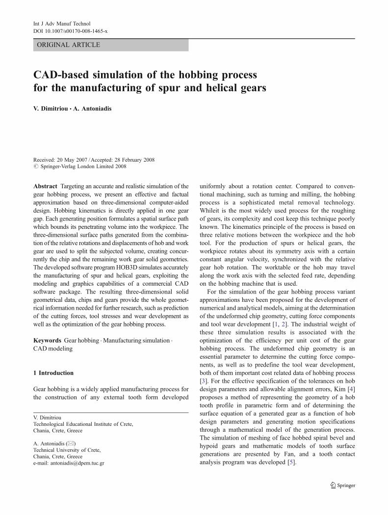
As presented in Fig. 2, after the initialization of the inputdata the solid geometry of the work gear is created in theCAD environment and one hob tooth rake face profile ismathematically and visually formed. At the same momentthe assembly of the effective cutting hob teeth (N) isdetermined and the kinematics of gear hobbing process isdirectly applied in one three-dimensional tooth gap of the
Fig. 1 Essential parameters of gear hobbing
Int J Adv Manuf Technol
gear due to the axisymetric configuration of the problem.Moreover, a three-dimensional surface is formed for everygenerating position (e.g., successive teeth penetrations),combining the allocation of the hob and the work gear,following a calculated spatial spline as a rail. These three-dimensional surface paths are used to identify the unde-formed chip solid geometry, to split the subjected volumeand to create finally the chip and the remaining work gearsolid geometries.
3 HOB3D simulation strategy
In this approach every rotation and displacement that istaking place between the hob and the work gear during thesimulation of the process are directly transferred to the hob. Aspresented in Fig. 3, the global coordinate system of the twoparts is fixed to the center of the upper base of theworkpiece, providing a steady reference system to thetravelling hob. The presented scheme of kinematics hasbeen adopted and in previous numerical approximationresearch works, mentioned at the introduction.
Without any loss of generality, the hob is considered tohave a tooth numbered-named: Tooth 0. The identificationvector v0 of Tooth 0 has its origin CH on the Yh axis of thehob and its end at the middle of the rake face, forming amodule that equals to dh/2. This vector determines thedirection of the Zh axis of the hob coordinate systemXhYhZh and is initially placed as an offset of the globalZ-axis, set at a vertical distance L1 from the origin of the
L1 : Vertical distance hob - gearL2 : Horizontal distance hob - gear
workgear
Z
d E
F
G
H
O
df
ha
Pitch circle
d =
helix
arc ofpitch circle
da/2
2 df sin(h )· · am·z2
Gear hobbing kinematics
θ 1 : angleHob rotationθ
θ
θ
2 : Gear anglerotation
Fig. 3 HOB3D simulation kinematics scheme
CAD based Gear Hobbing Simulation Program HOB3D
*
dh : out diameter mmside [ ]
Input Data
Ho
bG
eom
etry
Wo
rkg
ear
Geo
met
ryC
utt
ing
Co
nd
itio
ns
m : module [mm]z2 : number of teethha : helix angle [deg]
m : module [mm]ni : number of columnsz1 : number of hob origins
dg : outside diameter [mm]
fa : axial feed [mm/wrev]t : depth of cut [mm]v : [m/min]
Calculations
Generation of Workgear solid geometry
Determination of N effective cutting teeth
Generation of 3D-splinepath of hob tooth
Mathematical description of the hob tooth rake face
workgear
path of ahob tooth
Gea
rho
bbin
gpr
oces
s-R
esul
ts
3D surface geometrical descriptioof the hob tooth kinematic
Fo
r ac
tive
tee
th
Computation of theunderformed chipgeometry
...
toothprofile
spline
tooth revolvingdirection
n
solid
...
...cutting speed
Fig. 2 Flowchart of theprogram HOB3D
Int J Adv Manuf Technol
fixed XYZ global system, determining the region where thecutting starts. Once the simulation parameters are settled,the work gear solid model is generated and the assemblyof the effective cutting hob teeth is enabled. The momentthat the gear hobbing simulation starts is considered as timezero. At this time (t=0) the planes YZ and YhZh are paralleland their horizontal distance, steady for the whole simula-tion period, is set to: L2 ¼ dh=2ð Þ þ dg=2ð Þ � t. The
distance L2 practically determines the cutting depth, userdefined as an input parameter. To determine the settingangle θs, the XhYhZh hob coordinate system is rotated aboutthe Xh axis, so that the simulation process becomescompletely prescribed.
Using the spatial vector v0, it is easy to compute theidentification vectors vi of each of the N effective teethrelatively to v0, taking into account the hob geometrical
CAD based Gear hobbing kinematics
Y
Z
X
Chip solidgeometry
identification
Chip solid geometry
Workgear chip cross
section
detail A
hmax
path of ahob tooth
chip
tooth
cutting plane
cutting plane
A
tooth
revolvingposition
rake face
n1iCHi
n2i
dh
hob revolvingdirection
3d splinepath
workgear
workgear
vi
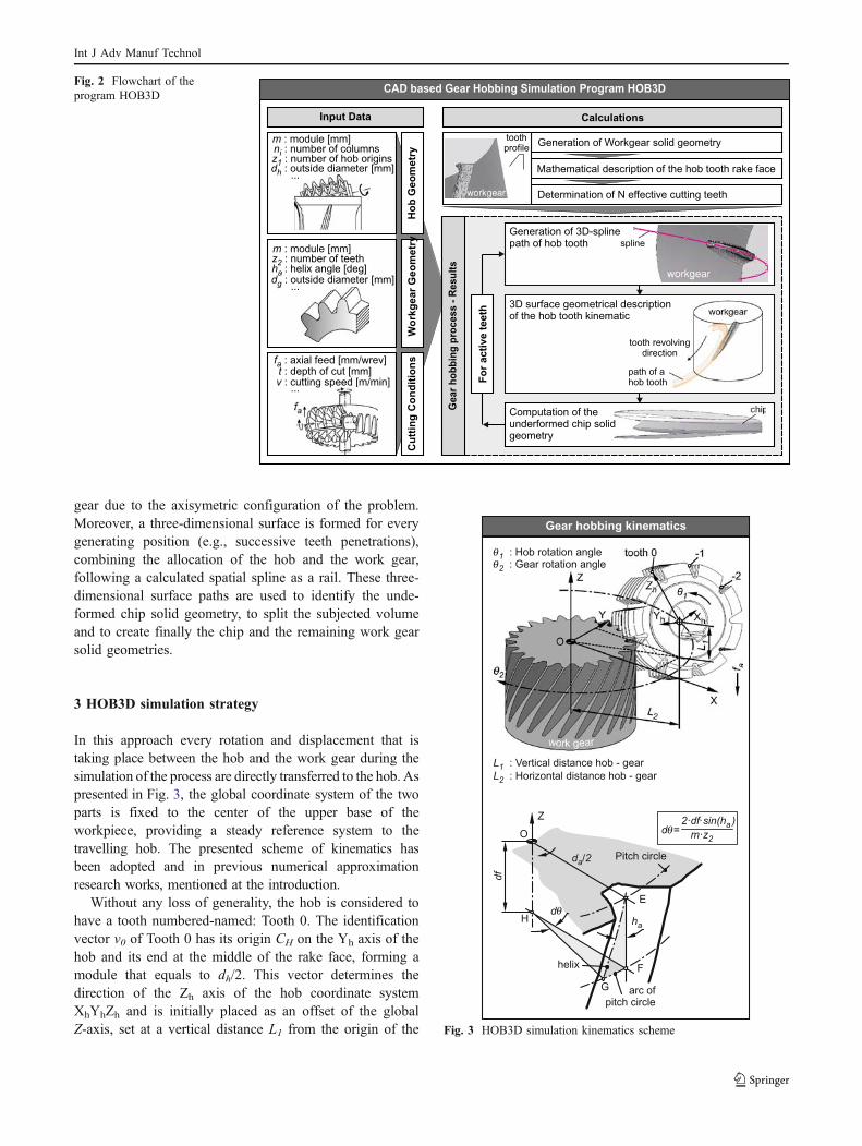
Fig. 4 Three-dimensional kinematics scheme in the CAD environment
HOB3D algorithmic diagram
Initializationof input data
Initialization of programparameters
Mathematical determinationof Vector v0
Generationof Work Gear cylinder
Mathematical determinationof spatial vectors
v , (C n ) and (C n )i H 1 i H 2 i
Application of forwardkinematics to vectorsv , (C n ) and (C n )i H 1 i H 2 i
Mathematical description of3D spline points,3D planesand corresponding profiles
Creation of 3D spline points,3D planes and profiles,3D spline trajectory
Generation of i-cutting tooth3D surface path
Subtraction of i-chip’ssolid geometry
i = l
i=f
Numerical implementation CAD system implementation
EndN Y
i = i+1
Determination of N effectivecutting teeth
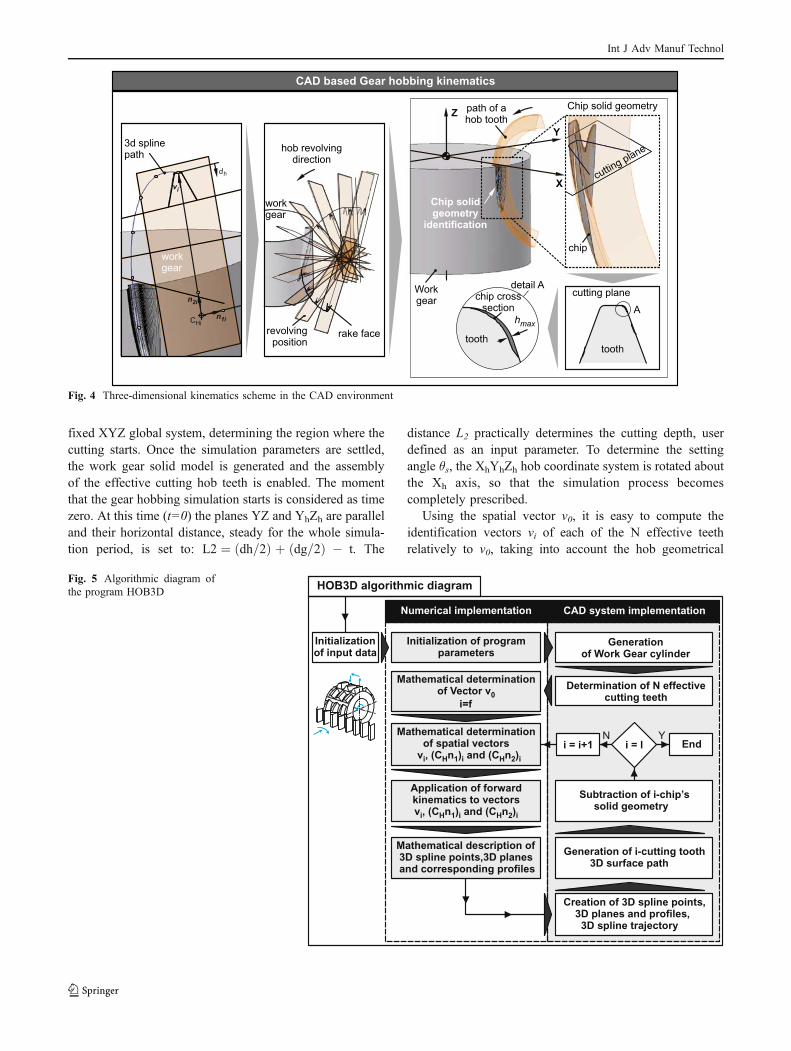
Fig. 5 Algorithmic diagram ofthe program HOB3D
Int J Adv Manuf Technol

input parameters. The independent parameter θ1 counts therotational angle of hob tool about its axis Yh during thecutting simulation. The parameter θ2 declares the rotationalangle of the hob tool about the work gear and fa the axial feedof the hob. θ2 and fa are dependent from θ1 and their valuesare determined according to the values of θ1 angle (see alsothe upper part of Fig. 3). The forward kinematics of each ofthe N effective cutting hob teeth occur in one gear tooth space(gap). Hereby, after the determination of v0 and consideringthat the identification vector of the first of the N cutting hobtooth vf is determined relatively to v0, the forward kinematicsare firstly applied to vf and sequentially to the followingvectors vi, until the last cutting hob tooth of the work cycle vl,simulating precisely the real manufacturing process.
In case of simulating helical gears fabrication, adifferential angular amount is added on the rotating systemof the gear, in order to increase or decrease the angularvelocity of the rotating workpiece, ensuring the propermeshing of the hob-cutting and gear-cut angles. Depending
on the type of the hobbing process a new angular parameterdθ has to be inserted to the whole kinematical chain for theacceleration or deceleration of θ2. The calculation of theparametrical value of dθ is taking place on the pitch circleas it is detailed schematically presented in the lower part ofFig. 3, constituting a section of significant importance.
As illustrated at Fig. 4, the prescribed kinematics chainis used for the construction of a three-dimensional splinepath in the CAD environment. This spline path occurs fromthe interpolation of points generated from the vi vector ofthe cutting hob teeth, that is properly transformed androtated by the help of the simulation parameters θ1, θ2and fa. Following the same tactic, the unit vectors (CH n1)iand (CH n2)i, described in the same Figure, are shifted androtated for the generation of a plane properly positionedinto the three-dimensional space, for every revolvingposition of the i-th cutting tooth.
The profile of the cutting hob tooth is formed on thetwo-dimensional space that is created by each one of these
Fig. 6 Maximum chip thickness on the revolving positions of every generating position of a full work cycle
Int J Adv Manuf Technol
spatial planes, as presented in the middle of Fig. 4. By theproper lofting of the constructed open profiles following therail of the constructed spatial spline, a three-dimensionalopen surface is created in one gear-gap tooth space. Thissurface path represents the generating position of the i-thcutting tooth and bounds its penetrating volume into theworkpiece. With the aid of this surface path, the solidgeometry of a chip is identified for every generatingposition, using the Boolean operations and the graphicscapabilities of the CAD environment. The chip geometry isrestricted by the external volume of the instantly formedworking gear gap, bounded outside the created surface. Theidentified solid geometry is then subtracted from theworkpiece leading to the generation of the continuousthree-dimensional solid geometries of the chip and theremaining work gear. Because of the output form of thesolid resulting parts of the simulation process, any kind ofpost-processing is primitively enabled. As can be seen atthe lower right section of Fig. 4 in detail A, the maximumthickness of an extracted solid geometry of a chip at acertain revolving position is detected. All of the imagespresented in Fig. 4 were captured from the CAD environ-ment during a simulation performed from HOB3D. Thewords, phases and arrows were added afterwards with thehelp of commercial image processing software for the betterexplanation of the images.
All of the previously mentioned simulation tasks arecontrolled by the developed program HOB3D that manipu-lates the modeling capabilities of the CAD system, forcingthe generation of the geometrical entities in it, collecting theoccurring geometrical data from it, and making all of theprogrammed numerical calculations. The continuous interac-tion of the CAD system with the numerical calculationsenvironment of the program is algorithmically described at
Fig. 5. After the insertion of the input data from the user theprogram parameters are initialized. The work gear cylindergeometry is generated and the number N of the effectivecutting teeth is computed. The spatial vector v0 is mathe-matically determined. The cutting tooth number parameter iis set to f (first cutting tooth number) and the vector vi andthe correspondent unit vectors (CHn1)i and (CHn2)i, essentialfor the construction of the spatial planes, are relative to v0mathematically determined. The forward kinematics of thehobbing procedure is applied to these vectors. The resultingnumerical data, prescribing the 3D spline points and the 3Dplanes, are used for the generation of the correspondingentities in the CAD environment. The generated 3D points areinterpolated for the construction of the 3D spline in the CADenvironment. For each created spatial plane, the correspon-dent tooth profile is mathematically formed and sketched inthe CAD system. The profiles are lofted properly, followingthe 3D spline trajectory forming the 3D surface path of thei-cutting tooth. The solid geometry included in the spatialsurface is subtracted from the work gear and saved as thei-chip geometry (see the enlargement detail of Fig. 4). Thei-counter takes the value i+1 and the same procedure isrepeated until i became equal to l (last cutting tooth number).
For the reduction of the computational effort and time,the overall rotation of the hob about its axis Yh is restrictedfrom 0 to 180 degrees (0°≤θ1≤180°) for every generatingposition of each effective cutting hob tooth i. This way onlythe motions that affect the resulting solid geometries aretaking place, without any influence to the process suffi-ciency, during the entire simulation process. After thecompletion of the sequential construction of every spatialsurface and the subtraction of the chip solid geometries, thegear gap is generated, formed by the collective work ofevery generating position.
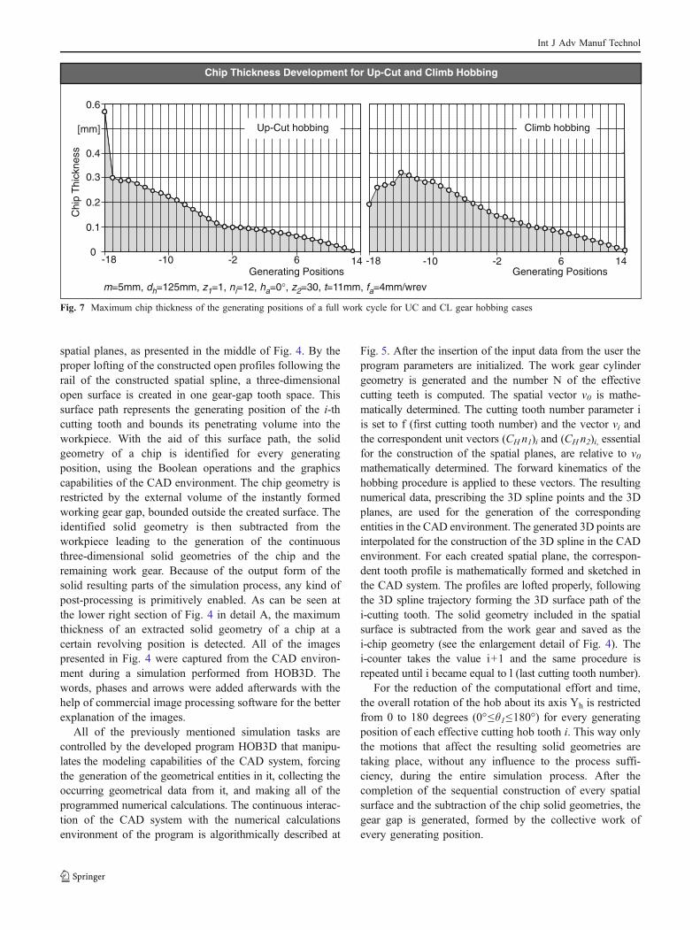
m d z n h z t f=5mm, =125mm, =1, =12, =0°, =30, =11mm, =4mm/wrevh 1 i a 2 a
Chip Thickness Development for Up-Cut and Climb Hobbing
Generating Positions
Chi
pT
hick
ness
0.6
[mm]
0.4
0.3
0.2
0.1
0-18 14-2-10 6-18 14-2-10 6
Up-Cut hobbing Climb hobbing
Generating Positions
Fig. 7 Maximum chip thickness of the generating positions of a full work cycle for UC and CL gear hobbing cases
Int J Adv Manuf Technol
4 HOB3D simulation results
The developed program HOB3D is used for the simulationof manufacturing of spur and helical gears, and its post-processing code is used for the determination of the solidchip thickness development. The proposed program wasverified and validated in a previous research work [18], bythe usage of the resulting three-dimensional solid geome-tries of the gear gaps generated by HOB3D. These gapprofiles were compared to the standard ones introduced byPetri [19] and DIN 3972 [20] and the calculated mean errorwas less than 10 μm for the working depth of producedgears. Such negligible deviations satisfy the computationalaccuracy expectations, and verify the sufficiency of thedeveloped code.
4.1 Simulation of the manufacturing process of spur gears
HOB3D is used for the simulation of manufacturing of aspur gear. The input data of the UC case processed and theoutput chip solid geometries of every generating positionare presented in Fig. 6. The cutting direction of the hob toolis indicated at the left of the gigure and the observation ofchips is taking place from the site of the hob. Examiningthe three-dimensional solid geometries of the displayedchips, we see that it is obvious that so much as the extremegeometrical changes of the chip shapes are sufficientlydetermined, even if it is parted from more than one domain.
The developed post-processing code of the program isused for the maximum thickness measurement of everychip of the work cycle on each revolving position. Ninety-one (0 to 90) assigned revolving positions (rp) that belongto the kinematics of each generating position (gp) are used.In case of intersection of a spatial plane of an rp with thesolid geometry of the chip, the maximum thickness (hmax)is identified and recorded. This sequence leads to thegeneration of the maximum thickness diagrams that arepresented below each chip at Fig. 6. As shown in the rightof the diagrams the measurement is taking place at anumber of nineteen revolving positions that range from the45th to the 63th rp.
For the improvement of the visualization of the resultingdiagrams, Fig. 6 is parted from two sections (upper andlower). At the upper section of the figure the sixteen firstgenerated chips are presented, corresponding to the gener-ating positions −18 to −3. The range of the maximumthickness at these diagrams is from 0 to 0.6 mm. As can beobserved, the values of the chip thicknesses are close tozero at the first revolving positions and approach theirmaxima close to the end of the chip. If the chip generated atthe position −18 is excluded because of the supremethickness value of 0.57 mm that reveals from the chip ofthe generating position −17 until −3 the maximum thick-nesses are oscillating from 0.3 mm to 0.1 mm with adescending rate. The reduction of the values of the chipthicknesses holds on and for the chips generated at the
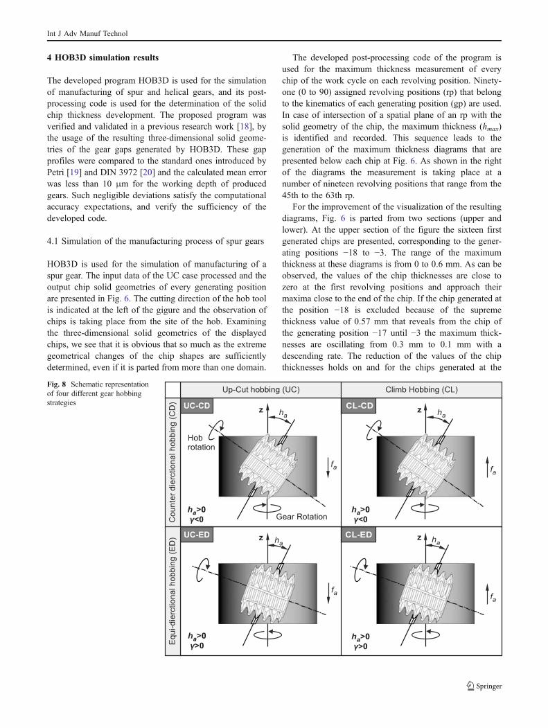
Fig. 8 Schematic representationof four different gear hobbingstrategies
Int J Adv Manuf Technol
positions −2 to 13. That is the reason why the range of thediagrams at these next sixteen generating positions (gp: −2to 13) presented in the lower part of the figure, varies form0 to 0.1 mm. It can be easily observed that the supremevalues of the chip thicknesses are following the samedescending route as the first sixteen and from the highervalue of 0.1 mm that appears at the generating position −2,the work cycle stops at the generating position 13, wherethe maximum chip thickness value is very close to zero.
The simulation data of the UC case are reused for theapproximation of the results of a CL case by changing onlythe sign of the axial feed (fa) input. After the evaluation ofthe chip solid geometries, the post-processor of HOB3D ismobilized for the measurement of the maximum chipthickness, in the same sense that was previously described.The maximum thicknesses of each generating position arerecorded and plotted to Fig. 7 for both of the UC and CLcases.
As shown in the two graphs of Fig. 7, the first effective(penetrating) generating position of both of the cases is theone prescribed from the cutting hob tooth with i=−18 (vf=v−18). For the UC case the last effective generating position
is the one prescribed from the cutting hob tooth with i=13(vl=v13) while for the CL case vl=v14. Except from the firstgenerating position of the UC where the measuredmaximum chip thickness approximates the value of 0.6millimetres, it is observed that the measured results for bothof the cases are oscillating in a range of 0 mm to 0.3 mmapproximately. The supreme values of the measuredmaximum thicknesses of the UC and CL cases is0.57 mm at gp=−18 and 0.32 mm at gp=−14, respectively.
4.2 Simulation of the manufacturing of helical gears
In the case of manufacturing helical gears, four differenthobbing strategies may be prescribed, depending on theprocess parameters that will be chosen, as it was thoroughlydescribed at the HOB3D modeling procedure paragraph.The schematic representation of these strategies for themanufacturing process of a helical gear with positive helixangle (ha>0°) is presented in Fig. 8.
HOB3D is used for the simulation of manufacturing of ahelical gear with helix angle ha=30° by these fourstrategies. The values of the input data of the examined
Chip Maximum Thickness Development for UC-CD, CL-CD, UC-ED and CL-ED Hobbing Processes
Max
imum
chip
thic
knes
sM
axim
umch
ipth
ickn
ess
0.52
0.39
0.26
0.13
0
0.52
0.39
0.26
0.13
0
Generating Positions
UC-CD CL-CD
CL-EDUC-ED
-7 2217 -20 7-17 -11 -8-14 -5 -2 1 4-7 22-1 5 11 17
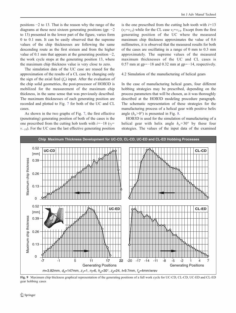
m d z n h z t f= mm, =1 mm, =1, = , = °, = , = mm, =4mm/wrev3.82 47 6 30 9.7h 1 i a 2 a24
Generating Positions
[mm]
[mm]
Fig. 9 Maximum chip thickness graphical representation of the generating positions of a full work cycle for UC-CD, CL-CD, UC-ED and CL-EDgear hobbing cases
Int J Adv Manuf Technol
cases are identical for each one of them except from thetool helix angle (γ) and the axial feed (fa). The sign of theseparameters denotes the hobbing strategy of each case, aspresented in Figs. 8 and 9.
After the evaluation of the chip solid geometries for eachone of the four different strategies, the post-processor ofHOB3D is mobilized for the measurement of the maximumchip thickness, by the same tactic that was formerlydescribed. The maximum thicknesses of each generatingposition are recorded and plotted to Fig. 9 for the UC-CD,CL-CD, UC-ED and CL-ED test cases.
As shown in the four graphs of Fig. 9, the first effective(penetrating) generating position of the UC-CD case is theone prescribed from the cutting hob tooth with i=22 (vf=v22) and the last from i=−7 (vl=v−7). This is the reason whythe black arrow in the graph is pointing to the left so as todenote the sequence of the cutting teeth. The same holds forthe CL-CD case were vf=v7 and vl=v−20. This is a result ofthe left-hand rotation of the workpiece and the numberingof the hob tool teeth that is used. As can be seen in the twographs of the -ED cases, the arrow is pointing to the reversedirection (from left to right) because of the right-hand
rotation of the gear and the numbering of the hob tool teeththat is used. At the UC-ED case vf=v−7 and vl=v18 and atthe CL-ED case vf=v−20 and vl=v7.
It should be observed that for all of the four cases themaximum chip thicknesses are oscillating in the samerange of 0 mm to 0.52 mm, and the supreme value ofeach one of them approximates the value of the 0.5 mm.Also, it should be noted that the diagrams of the UC-CDcase and CL-ED case appear the same behavior ofoscillations and the same holds for the CL-CD and UC-ED cases.
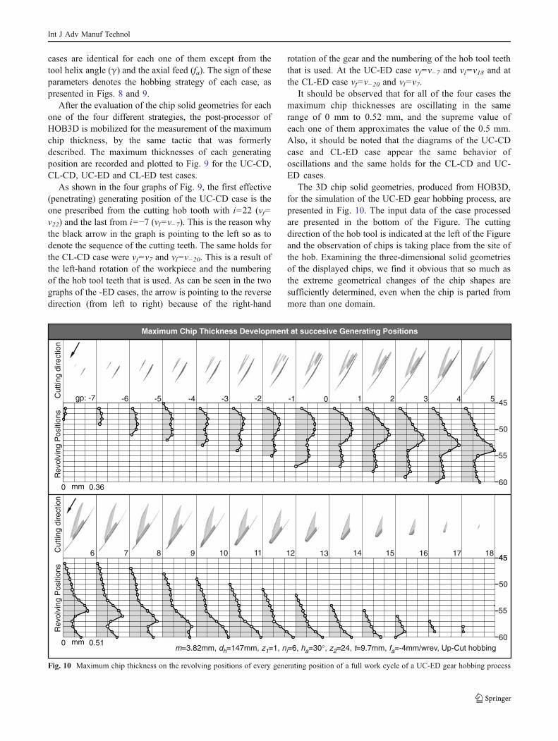
The 3D chip solid geometries, produced from HOB3D,for the simulation of the UC-ED gear hobbing process, arepresented in Fig. 10. The input data of the case processedare presented in the bottom of the Figure. The cuttingdirection of the hob tool is indicated at the left of the Figureand the observation of chips is taking place from the site ofthe hob. Examining the three-dimensional solid geometriesof the displayed chips, we find it obvious that so much asthe extreme geometrical changes of the chip shapes aresufficiently determined, even when the chip is parted frommore than one domain.
m d z n h z t f=3.82mm, =147mm, =1, =6, =30°, =24, =9.7mm, =-4mm/wrev, hobbingh 1 i a 2 a Up-Cut
mm 0.360
Rev
olvi
ngP
ositi
ons
60
45
50
55
mm 0.51060
45
50
55
Rev
olvi
ngP
ositi
ons
Maximum Chip Thickness Development at succesive Generating Positions
gp: -7 -6 -5 -4 -3 -2 -1 0 1 2 3 4 5Cut
ting
dire
ctio
n
457 8 9 10 11 12 13 14 15 16 17 186C
uttin
gdi
rect
ion
Fig. 10 Maximum chip thickness on the revolving positions of every generating position of a full work cycle of a UC-ED gear hobbing process
Int J Adv Manuf Technol
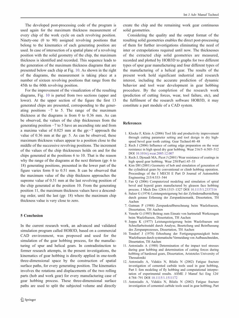
The developed post-processing code of the program isused again for the maximum thickness measurement ofevery chip of the work cycle on each revolving position.Ninety-one (0 to 90) assigned revolving positions thatbelong to the kinematics of each generating position areused. In case of intersection of a spatial plane of a revolvingposition with the solid geometry of the chip, the maximumthickness is identified and recorded. This sequence leads tothe generation of the maximum thickness diagrams that arepresented below each chip at Fig. 10. As shown in the rightof the diagrams, the measurement is taking place at anumber of sixteen revolving positions that range from the45th to the 60th revolving position.
For the improvement of the visualization of the resultingdiagrams, Fig. 10 is parted from two sections (upper andlower). At the upper section of the figure the first 13generated chips are presented, corresponding to the gener-ating positions −7 to 5. The range of the maximumthickness at the diagrams is from 0 to 0.36 mm. As canbe observed, the values of the chip thicknesses from thegenerating position −7 to 5 have an ascending rate and froma maxima value of 0.025 mm at the gp:−7 approach thevalue of 0.36 mm at the gp: 5. As can be observed, thesemaximum thickness values appear to a position close to themiddle of the successive revolving positions. The incrementof the values of the chip thicknesses holds on and for thechips generated at the positions 6 to 10. That is the reasonwhy the range of the diagrams at the next thirteen (gp: 6 to18) generating positions, presented in the lower part of thefigure varies form 0 to 0.51 mm. It can be observed thatthe maximum value of the chip thickness approaches thesupreme value of 0.51 mm at the last revolving position ofthe chip generated at the position 10. From the generatingposition 11, the maximum thickness values have a descend-ing order, until the last (gp: 18) where the maximum chipthickness value is very close to zero.
5 Conclusion
In the current research work, an advanced and validatedsimulation program called HOB3D, based on a commercialCAD environment, was proposed and used for thesimulation of the gear hobbing process, for the manufac-turing of spur and helical gears. In contradistinction toformer research attempts, in the present investigations, thekinematics of gear hobbing is directly applied in one-tooththree-dimensional space by the construction of spatialsurface paths, for every generating position. The kinematicsinvolves the rotations and displacements of the two rollingparts (hob and work gear) for every manufacturing case ofgear hobbing process. These three-dimensional surfacepaths are used to split the subjected volume and directly
create the chip and the remaining work gear continuoussolid geometries.
Considering the quality and the output format of theresulting solid geometries enables the direct post-processingof them for further investigations eliminating the need ofinter or extrapolations required until now. The thicknessesof the extracted chip solid geometries are measured,recorded and plotted by HOB3D to graphs for two differenttypes of spur gear manufacturing and four different types ofthe manufacturing of a helical gear. The results of thepresent work hold significant industrial and researchinterest, including the accurate prediction of dynamicbehavior and tool wear development in gear hobbingprocedure. By the completion of the research work(prediction of cutting forces, wear, tool failure, etc), andthe fulfilment of the research software HOB3D, it mayconstitute a part module of a CAD system.
References
1. Klocke F, Klein A (2006) Tool life and productivity improvementthrough cutting parameter setting and tool design in dry high-speed bevel gear tooth cutting. Gear Technol:40–48
2. Rech J (2006) Influence of cutting edge preparation on the wearresistance in high speed dry gear hobbing. Wear 216/5–6:505–512DOI 10.1016/j.wear.2005.12.007
3. Rech J, Djouadi MA, Picot J (2001) Wear resistance of coatings inhigh speed gear hobbing. Wear 250/Part1:45–53
4. Kim DH (2001) Geometry of hob and simulation of generation ofthe cylindrical gears by conventional or climb hobbing operation.Proceedings of the I MECH E Part D Journal of AutomobileEngineering 215/4:533–544
5. Fan Q (2006) Computerized modeling and simulation of spiralbevel and hypoid gears manufactured by gleason face hobbingprocess. J Mech Des 128/6:1315–1327 DOI 10.1115/1.2337316
6. Sulzer G (1974) Leistungssteigerung bei der Zylinderradherstellungdurch genaue Erfassung der Zerspankinematik, Dissertation, THAachen
7. Gutman P (1988) Zerspankraftberechnung beim Waelzfraesen,Dissertation, TH Aachen
8. Venohr G (1985) Beitrag zum Einsatz von hartmetall Werkzeugenbeim Waelzfraesen, Dissertation, TH Aachen
9. Joppa K (1977) Leistungssteigerung beim Waelzfraesen mitSchnellarbeitsstahl durch Analyse, Beurteilung und Beinflussungdes Zerspanprozesses, Dissertation, TH Aachen
10. Tondorf J (1978) Erhoehung der Fertigungsgenauigkeit beimWaelzfraesen durch systematischeVermeidung vonAufbauschneiden,Dissertation, TH Aachen
11. Antoniadis A (1988) Determination of the impact tool stressesduring gear hobbing and determination of cutting forces duringhobbing of hardened gears, Dissertation, Aristoteles University ofThessaloniki
12. Antoniadis A, Vidakis N, Bilalis N (2002) Fatigue fractureinvestigation of cemented carbide tools used in gear hobbing,Part I: fem modeling of fly hobbing and computational interpre-tation of experimental results. ASME J Manuf Sci Eng 124/4:784–791 DOI 10.1115/1.1511172
13. Antoniadis A, Vidakis N, Bilalis N (2002) Fatigue fractureinvestigation of cemented carbide tools used in gear hobbing, Part
Int J Adv Manuf Technol

II: the effect of cutting parameters on the level of tool stresses - aquantitive parametric analysis. ASME JManuf Sci Eng 124/4:792–798 DOI 10.1115/1.1511173
14. Sinkevicius V (1999) Simulation of gear hobbing geometricalsize. Mechanika (Kaunas University of Technology Journal) 5(50):34–39
15. Sinkevicius V (2001) Simulation of Gear Hobbing forces.Mechanika (Kaunas University of Technology Journal) 2(28):58–63
16. Komori M, Sumi M, Kubo A (2004) Method of preventing cuttingedge failure of hob due to chip crush. JSME Int J Ser C Mech SystMach Elem Manuf 47(4):1140–1148
17. Komori M, Sumi M, Kubo A (2004) Simulation of hobbing foranalysis of cutting edge failure due to chip crush. Gear Technol,64–69
18. Dimitriou V, Vidakis N, Antoniadis A (2007) Advanced computeraided design simulation of gear hobbing by means of 3-dimensional kinematics modeling. ASME J Manuf Sci Eng 129\5:911–918 DOI 10.1115/1.2738947
19. Petri H (1975) Zahnhuß - Analyse bei außenverzahnten Evolventen-stirnraedern: Teil III Berechnung. Antriebstechnik 14(5):289–297
20. DIN 3972 (1992) Bezugsprofile von Verzahnwerkzeugen fuerEvolventen-Verzahnungen nach DIN 867. Taschenbuch 106,Beuth Verlag, Berlin
Int J Adv Manuf Technol