CA View Installation Guide
278
Installation Guide Version 12.0 CA View®
-
Upload
khangminh22 -
Category
Documents
-
view
0 -
download
0
Transcript of CA View Installation Guide

Installation Guide Version 12.0
CA View®

This Documentation, which includes embedded help systems and electronically distributed materials, (hereinafter referred to as the “Documentation”) is for your informational purposes only and is subject to change or withdrawal by CA at any time.
This Documentation may not be copied, transferred, reproduced, disclosed, modified or duplicated, in whole or in part, without the prior written consent of CA. This Documentation is confidential and proprietary information of CA and may not be disclosed by you or used for any purpose other than as may be permitted in (i) a separate agreement between you and CA governing your use of the CA software to which the Documentation relates; or (ii) a separate confidentiality agreement between you and CA.
Notwithstanding the foregoing, if you are a licensed user of the software product(s) addressed in the Documentation, you may print or otherwise make available a reasonable number of copies of the Documentation for internal use by you and your employees in connection with that software, provided that all CA copyright notices and legends are affixed to each reproduced copy.
The right to print or otherwise make available copies of the Documentation is limited to the period during which the applicable license for such software remains in full force and effect. Should the license terminate for any reason, it is your responsibility to certify in writing to CA that all copies and partial copies of the Documentation have been returned to CA or destroyed.
TO THE EXTENT PERMITTED BY APPLICABLE LAW, CA PROVIDES THIS DOCUMENTATION “AS IS” WITHOUT WARRANTY OF ANY KIND, INCLUDING WITHOUT LIMITATION, ANY IMPLIED WARRANTIES OF MERCHANTABILITY, FITNESS FOR A PARTICULAR PURPOSE, OR NONINFRINGEMENT. IN NO EVENT WILL CA BE LIABLE TO YOU OR ANY THIRD PARTY FOR ANY LOSS OR DAMAGE, DIRECT OR INDIRECT, FROM THE USE OF THIS DOCUMENTATION, INCLUDING WITHOUT LIMITATION, LOST PROFITS, LOST INVESTMENT, BUSINESS INTERRUPTION, GOODWILL, OR LOST DATA, EVEN IF CA IS EXPRESSLY ADVISED IN ADVANCE OF THE POSSIBILITY OF SUCH LOSS OR DAMAGE.
The use of any software product referenced in the Documentation is governed by the applicable license agreement and such license agreement is not modified in any way by the terms of this notice.
The manufacturer of this Documentation is CA.
Provided with “Restricted Rights.” Use, duplication or disclosure by the United States Government is subject to the restrictions set forth in FAR Sections 12.212, 52.227-14, and 52.227-19(c)(1) - (2) and DFARS Section 252.227-7014(b)(3), as applicable, or their successors.
Copyright © 2012 CA. All rights reserved. All trademarks, trade names, service marks, and logos referenced herein belong to their respective companies.

CA Technologies Product References
This document references the following CA Technologies products:
■ CA 1®
■ CA ACF2™
■ CA Balancing™
■ CA Common Services
■ CA Connect™
■ CA Deliver™
■ CA DRAS™
■ CA Easytrieve® Report Generator
■ CA Mainframe Software Manager (CA MSM)
■ CA Output Management Web Viewer
■ CA Output Management Document Viewer
■ CA Roscoe®
■ CA Spool™
■ CA TLC (CA Total License Care)
■ CA Top Secret® for z/OS

Contact CA Technologies
Contact CA Support
For your convenience, CA Technologies provides one site where you can access the information that you need for your Home Office, Small Business, and Enterprise CA Technologies products. At http://ca.com/support, you can access the following resources:
■ Online and telephone contact information for technical assistance and customer services
■ Information about user communities and forums
■ Product and documentation downloads
■ CA Support policies and guidelines
■ Other helpful resources appropriate for your product
Providing Feedback About Product Documentation
If you have comments or questions about CA Technologies product documentation, you can send a message to [email protected].
To provide feedback about CA Technologies product documentation, complete our short customer survey which is available on the CA Support website at http://ca.com/docs.

Contents 5
Contents
Chapter 1: Overview 11
Audience .................................................................................................................................................................... 11
How the Installation Process Works........................................................................................................................... 12
Installation Considerations ................................................................................................................................. 14
First Time Installation or Upgrade .............................................................................................................................. 15
Chapter 2: Preparing for Installation 17
Hardware Requirements ............................................................................................................................................ 17
Supported Operating Systems ............................................................................................................................ 17
Supported Cryptographic Hardware ................................................................................................................... 17
CA View Target Libraries ..................................................................................................................................... 18
CA View Distribution Libraries ............................................................................................................................ 19
CA DRAS Target Libraries .................................................................................................................................... 19
CA DRAS Distribution Libraries ............................................................................................................................ 20
EBC Distribution Libraries.................................................................................................................................... 20
Software Requirements ............................................................................................................................................. 21
Common Component SYSMODs ......................................................................................................................... 21
CA View Component SYSMODS .......................................................................................................................... 21
CA DRAS Component SYSMODS .......................................................................................................................... 21
Common Services Component ............................................................................................................................ 21
EMC Centera Disk Option .................................................................................................................................... 22
CA Common Services Requirements .......................................................................................................................... 22
CA Common Services Installation Considerations............................................................................................... 22
CAIRIM ................................................................................................................................................................ 23
CA LMP ................................................................................................................................................................ 23
Common Services Required for CA DRAS ............................................................................................................ 23
Common Services Required for z/OS .................................................................................................................. 25
Health Checker Common Service ........................................................................................................................ 25
CA DRAS Is Included with CA View ............................................................................................................................. 26
Overview of the Cooperative Process ................................................................................................................. 26
Security Requirements ............................................................................................................................................... 28
Storage Requirements ................................................................................................................................................ 29
Other Requirements ................................................................................................................................................... 29
SVC Dump Data Sets............................................................................................................................................ 29
JCL Procedures .................................................................................................................................................... 30
Concurrent Releases .................................................................................................................................................. 31

6 Installation Guide
Concurrent Release Considerations .................................................................................................................... 32
Relationship between Versions of CA View and CA Deliver ................................................................................ 33
Chapter 3: Installing Your Product Using CA MSM 35
How to Use CA MSM: Scenarios ................................................................................................................................. 35
How to Acquire a Product ................................................................................................................................... 35
How to Install a Product ...................................................................................................................................... 36
How to Maintain Existing Products ..................................................................................................................... 37
How to Deploy a Product .................................................................................................................................... 38
How to Configure a Product ................................................................................................................................ 39
Access CA MSM Using the Web-Based Interface ....................................................................................................... 40
Chapter 4: Installing Your Product from Pax-Enhanced ESD 41
How to Install a Product Using Pax-Enhanced ESD .................................................................................................... 41
How the Pax-Enhanced ESD Download Works ................................................................................................... 43
ESD Product Download Window ......................................................................................................................... 43
USS Environment Setup ...................................................................................................................................... 46
Allocate and Mount a File System .............................................................................................................................. 47
Copy the Product Pax Files into Your USS Directory .................................................................................................. 50
Download Using Batch JCL .................................................................................................................................. 51
Download Files to Mainframe through a PC ....................................................................................................... 54
Create a Product Directory from the Pax File ............................................................................................................ 55
Sample Job to Execute the Pax Command (Unpackage.txt) ............................................................................... 56
Copy Installation Files to z/OS Data Sets .................................................................................................................... 56
Receive the SMP/E Package ....................................................................................................................................... 57
How to Install Products Using Native SMP/E JCL ................................................................................................ 58
Prepare the SMP/E Environment for Pax Installation ......................................................................................... 58
Run the Installation Jobs for a Pax Installation ................................................................................................... 59
Clean Up the USS Directory ........................................................................................................................................ 60
Apply Maintenance .................................................................................................................................................... 61
HOLDDATA .......................................................................................................................................................... 62
Chapter 5: Installing Your Product from Tape 65
Unload the Sample JCL from Tape ............................................................................................................................. 66
How to Install Products Using Native SMP/E JCL ....................................................................................................... 67
Prepare the SMP/E Environment for Tape Installation ....................................................................................... 67
Run the Installation Jobs for a Tape Installation ................................................................................................. 68
Apply Maintenance .................................................................................................................................................... 69
HOLDDATA .......................................................................................................................................................... 70
System HOLDDATA .............................................................................................................................................. 70

Contents 7
External HOLDDATA ............................................................................................................................................ 72
Chapter 6: Installing Your Product from DVD 73
Overview .................................................................................................................................................................... 73
Purpose ............................................................................................................................................................... 73
Audience ............................................................................................................................................................. 73
Frequently Asked Questions ............................................................................................................................... 73
CA Product Documentation ................................................................................................................................ 76
Introduction to Electronic Software Delivery ............................................................................................................. 76
What is Electronic Software Delivery? ................................................................................................................ 76
Pax-Enhanced ESD Procedures ................................................................................................................................... 79
How to Install a Product from a DVD Using Pax-Enhanced ESD .......................................................................... 79
The Installation Procedure .................................................................................................................................. 79
References .................................................................................................................................................................. 83
IBM Reference Manual ....................................................................................................................................... 83
Common USS Commands .................................................................................................................................... 83
Chapter 7: Starting Your Product 85
How to Complete Configuration With CA MSM ......................................................................................................... 85
Authorize Program Load Libraries ....................................................................................................................... 85
Enter the LMP Code ............................................................................................................................................ 85
Define Security Rules .......................................................................................................................................... 88
Install the ISPF Online Retrieval Option .............................................................................................................. 88
Install the TSO Online Retrieval Option .............................................................................................................. 91
Install the XMS Online Interfaces (Optional) ....................................................................................................... 92
How to Configure Without CA MSM .......................................................................................................................... 92
Step 1. Authorize Program Load Libraries ........................................................................................................... 92
Step 2. Enter the LMP Code ................................................................................................................................ 93
Step 3. Exclude Archive Tapes from Tape Management Abend Retention ........................................................ 96
Step 4. Create the Database ............................................................................................................................... 96
Step 5. Modify the Skeleton JCL .......................................................................................................................... 97
Step 6. Load the Online Panels and JCL Library ................................................................................................. 101
Step 7. Load the Model Banner Pages .............................................................................................................. 104
Step 8. (Optional) Add the Microfiche Option .................................................................................................. 105
Step 9. (Optional) Set up Job Accounting .......................................................................................................... 106
Step 10: (Optional) Set Up Backup Tape Tracking ............................................................................................. 106
Step 11: (Optional) Install System Extensions ................................................................................................... 107
Step 12: (Optional) Exceptional Condition Checking ........................................................................................ 109
Step 13: (Optional) Replace or Modify User Exits ............................................................................................. 110
Step 14: (Optional) Set up for Multiple CPUs .................................................................................................... 112
Step 15: (Optional) Install Optional Online Interfaces ...................................................................................... 114

8 Installation Guide
Step 16: (Optional) Install Optional Features .................................................................................................... 114
Step 17: (Optional) Download the EMC Centera API for CA View .................................................................... 114
Step 18: Add the Archival Task Start Procedure ............................................................................................... 114
Step 19: Use SARINIT to Set the Final Initialization Parameter Values ............................................................. 116
Step 20. (Optional) Customize and Configure CA DRAS .................................................................................... 117
Post-Installation Considerations .............................................................................................................................. 117
Chapter 8: Migration Information 119
Upgrading from Release 11.7, r11.6, r11.5, and r11 ................................................................................................ 119
Installation Steps to Upgrade to Version12.0 ................................................................................................... 120
Configuration Steps to Upgrade to Version 12.0 without CA MSM .................................................................. 121
Chapter 9: Reverting to a Prior Installation 127
Revert to Release 11.7 ............................................................................................................................................. 127
Revert to r11.6 ......................................................................................................................................................... 128
Revert to r11.5 ......................................................................................................................................................... 129
Chapter 10: Installing the Online Interfaces 131
How to Complete Configuration of the XMS Online Interfaces with CA MSM ........................................................ 131
Define Security Requirements .......................................................................................................................... 132
Install the ISPF/Cross-Memory Online Retrieval Option ................................................................................... 132
Install the TSO/Cross-Memory Online Retrieval Option ................................................................................... 138
Install the VTAM Online Retrieval Option ......................................................................................................... 140
Install the CA Roscoe/Cross-Memory Online Retrieval Option ......................................................................... 144
Install the CICS Pseudo-Conversational Option ................................................................................................ 146
Install the IMS Online Retrieval Option ............................................................................................................. 155
How to Configure the Online Interfaces Without CA MSM ..................................................................................... 160
Online Interfaces ............................................................................................................................................... 160
Cross-Memory Services Interface (XMS) ........................................................................................................... 161
Cross-Memory Drivers for Interfaces ................................................................................................................ 162
Install the ISPF Online Retrieval Option ............................................................................................................ 162
Install the TSO Online Retrieval Option ............................................................................................................ 167
Install the CA Roscoe Online Retrieval Option .................................................................................................. 169
Install the Cross-Memory Services .................................................................................................................... 170
Install the ISPF/Cross-Memory Online Retrieval Option ................................................................................... 191
Install the TSO/Cross-Memory Online Retrieval Option ................................................................................... 197
Install the VTAM Online Retrieval Option ......................................................................................................... 199
Install the CA Roscoe/Cross-Memory Online Retrieval Option ......................................................................... 203
Install the CICS Pseudo-Conversational Option ................................................................................................ 205
Install the IMS Online Retrieval Option ............................................................................................................. 217

Contents 9
TSO, ISPF, CA Roscoe and Cross-Memory Address Spaces ............................................................................... 222
Multiple Cross-Memory Region Requirements ................................................................................................. 222
Prepare to Start the Cross Memory Task .......................................................................................................... 223
Start the Cross Memory Task ............................................................................................................................ 223
Chapter 11: Installing the Features 225
Install ERO ................................................................................................................................................................ 225
Step 1: Set the ERO Initialization Parameters ................................................................................................... 225
Step 2: (Optional) Create the ERO Table Statements ....................................................................................... 226
Install the VTAM Print Option .................................................................................................................................. 226
Configuration Requirements ............................................................................................................................. 226
Step 1: Define the Application Program to VTAM ............................................................................................ 227
Step 2: (Optional) Verify the CICS Table Entries ................................................................................................ 227
Step 3: Set the VTAM Print Option Initialization Parameters ........................................................................... 227
Install the Interface with Print Management ........................................................................................................... 228
CA Spool Requirement ...................................................................................................................................... 228
Initialization Parameters ................................................................................................................................... 228
Install the Interface with ACIF (AFP Report Archival) ............................................................................................... 228
Step 1: Define JES2 Initialization Statements .................................................................................................... 229
Step 2: Define JES3 Initialization Statements .................................................................................................... 232
Step 3: Define an ACIF Archiver PROC .............................................................................................................. 234
Step 4: Define FSA Device Control Statements ................................................................................................. 235
Install a CA View PDF Archiver ................................................................................................................................. 238
Step 1: Define JES2 Initialization Statements .................................................................................................... 239
Step 2: Define JES3 Initialization Statements .................................................................................................... 242
Step 3: Define a PDF Archiver PROC ................................................................................................................. 244
Step 4: Define FSA Device Control Statements ................................................................................................. 246
Install the Viewing Option Interface ........................................................................................................................ 247
Install the Global Subsystem Interface ..................................................................................................................... 248
Install the Optical Disk Interface .............................................................................................................................. 248
Install the Extended Access Server for Tape and Robotics....................................................................................... 248
Install the FSS Collector ............................................................................................................................................ 249
FSS Collector Terms ........................................................................................................................................... 249
Installation Steps ............................................................................................................................................... 250
Step 1: Define JES2 Initialization Statements .................................................................................................... 250
Step 2: Define JES3 Initialization Statements .................................................................................................... 253
Step 3. Define a VIEW Archiver PROC ............................................................................................................... 256
Step 4: Define FSA Device Control Statements ................................................................................................. 257
Step 5: Define FSS Report Control Statements ................................................................................................. 259
Install the EMC Centera Disk Option ........................................................................................................................ 259

10 Installation Guide
Appendix A: Installation Worksheets 261
Data Set Qualifiers and SMP Parameters ................................................................................................................. 261
Initialization Parameter Worksheet ......................................................................................................................... 262
Expanded Retention Option (ERO) Initialization Parameters ................................................................................... 266
Archival Started Task Worksheet ............................................................................................................................. 267
Accounting Data ................................................................................................................................................ 267
Create Backup Report ....................................................................................................................................... 267
Create Optical Migration Report ....................................................................................................................... 267
Tracking Backup Tapes (Highly Recommended) ............................................................................................... 268
Exceptional Condition Checking Control Statements ....................................................................................... 268
Expanded Retention Option (ERO) Control Statements ................................................................................... 268
Appendix B: Integration with CA OPS/MVS EMA 269
Overview .................................................................................................................................................................. 269
Ensure that CA OPS/MVS Is Enabled for Capturing These Events ............................................................................ 270
CA View Active State Events ..................................................................................................................................... 270
CA View Heartbeat Events ....................................................................................................................................... 272
Index 275

Chapter 1: Overview 11
Chapter 1: Overview
This guide describes how to install and implement CA View.
This section contains the following topics:
Audience (see page 11) How the Installation Process Works (see page 12) First Time Installation or Upgrade (see page 15)
Audience
This guide is targeted to the systems programmer who will install, use, and maintain CA View.
This guide assumes you are familiar with CA View and IBM computer system terms and concepts. You should also have a working knowledge of MVS online facilities such as ISPF, since the CA View panels behave in a similar fashion.
This guide assumes that you:
■ Are familiar with CA View and IBM computer system terms and concepts
■ Have a working knowledge of MVS online facilities such as ISPF because the CA View panels behave in a similar fashion.

How the Installation Process Works
12 Installation Guide
How the Installation Process Works
CA Technologies has standardized product installations across all mainframe products. Installation uses the following process:
■ Acquisition—Transports the software to your z/OS system.
■ Installation using SMP/E—Optionally creates a CSI environment and runs the RECEIVE, APPLY and ACCEPT steps. The software is untailored.
■ Deployment—Copies the target libraries to another system or LPAR.
■ Configuration—Creates customized load modules, bringing the software to an executable state.
CA MSM provides a web-based interface to make the standardized installation process easier. Using CA MSM, someone with limited knowledge of JCL and SMP/E can install a product.
Note: If you do not have CA MSM, you can download it from the Download Center at the CA Support Online website. Follow the installation instructions in the CA Mainframe Software Manager documentation bookshelf on the CA Mainframe Software Manager product page. The standardized installation process can also be completed manually.
To install your product, do the following tasks:
1. Prepare for the installation by confirming that your site meets all installation requirements (see page 17).
2. Use one of the following methods to acquire the product:
■ Download the software from CSO using CA MSM (see page 35).
■ Download the software from CSO using Pax-Enhanced Electronic Software Delivery (ESD) (see page 41).
■ Order a tape or a DVD.
3. Perform an SMP/E installation using one of the following methods:
■ If you used CA MSM to acquire the product, start the SMP/E step from the SMP/E Environments tab in CA MSM.
■ If you used ESD to acquire the product, you can install the product in the following ways:
– Install the product manually.
– Use the Insert New Product option in CA MSM to complete the SMP/E installation.
■ If you used a tape (see page 65) or DVD, install the product manually.
Note: If a CA Recommended Service (CA RS) package is published for your product, install it before continuing with deployment.

How the Installation Process Works
Chapter 1: Overview 13
4. Deploy the target libraries using one of the following methods:
■ If you are using CA MSM, deployment is required; it is a prerequisite for configuration.
■ If you are using a manual process, deployment is an optional step.
Note: Deployment is considered part of starting your product (see page 85).
5. Configure your product using CA MSM or manually.
Note: Configuration is considered part of starting your product (see page 85).

How the Installation Process Works
14 Installation Guide
Installation Considerations
Before installation, you must prepare your system, assemble your materials, and then follow the installation steps exactly and in order. Use the following list as a guide for the installation process.
1. Verify that CA Common Services are installed on your system, and that the required hardware, software, and libraries are prepared.
– CA View uses the CAI Resource Initialization Manager CAIRIM portion of the CA Common Services.
– CAIRIM prepares the operating system for CA products and components, and then executes them.
– CA DRAS requires the CAIENF (Event Notification Facility) and the CAICCI (Common Communications Interface) components of the CA Common Services.
Note: For more information about system requirements, see the chapter "System Requirements".
2. Install CA View using one of the four installation methods -- CA MSM, PAX Enhanced ESD, DVD, or from a product tape.
3. Use options and initialization parameters to customize the solution according to the needs of your site, as follows:
■ Configure your CA View system.
■ Install the online interfaces including the cross-memory and online retrieval options for ISPF, TSO, VTAM, CA Roscoe Interactive Environment (CA Roscoe), CICS and IMS.
Note: For more information about installing online interfaces, see the chapter "Installing Online Interfaces."
■ Install the features including:
■ ERO, the VTAM print option
■ The CA Spool interface option
■ The CA View ACIF interface, the CA View Proprietary Print Stream (PPS) Viewing Option for Xerox interface
■ CA GSS, the Global Subsystem interface
■ FSS, the Functional Subsystem Collector.
Note: See the chapter "Installing Features" for more information.
4. Optionally, configure and customize CA DRAS. For more information, see the CA DRAS Operations Guide.

First Time Installation or Upgrade
Chapter 1: Overview 15
First Time Installation or Upgrade
Use the tasks presented in this chapter, and in the Installing Online Interfaces and Installing Features sections of the "Configuring Your Product" chapter whether you are installing CA View Version 12.0 for the first time or upgrading from a prior release, as follows:
■ If you are installing for the first time, perform:
■ All steps in this chapter as indicated
■ The tasks in the Installing Online Interfaces and Installing Features chapters to install the optional online interfaces and features that are appropriate for your site.
■ If you are upgrading from a prior release, perform:
All steps in this chapter as indicated and the tasks in the Installing Online Interfaces and Installing Features chapters as appropriate for your site.
Note: Some steps must be performed exactly as presented; several steps must be modified according to the instructions in the Upgrading from a Prior Release section.
Important! Although much of the JCL is similar to the previous release, you must use the new version because the naming conventions have changed and new files have been introduced. Be sure to retain your previous CA View JCL files and load libraries


Chapter 2: Preparing for Installation 17
Chapter 2: Preparing for Installation
This section describes what you need to know and do before you install the product.
This section contains the following topics:
Hardware Requirements (see page 17) Software Requirements (see page 21) CA Common Services Requirements (see page 22) CA DRAS Is Included with CA View (see page 26) Security Requirements (see page 28) Storage Requirements (see page 29) Other Requirements (see page 29) Concurrent Releases (see page 31)
Hardware Requirements
This section describes the hardware and libraries that are required for CA View and CA DRAS.
Supported Operating Systems
IBM z/OS 1.9 and higher is the minimum software required to run this release of CA View and meet the performance requirements.
Supported Cryptographic Hardware
Two cryptographic hardware choices are available for you to use on various systems:
■ Cryptographic Coprocessor Facility (CCF)
A standard component on z900 and a no-cost option for z800. On z800 and z900 systems, ICSF requires CCF.
■ CP Assist for Cryptographic Functions (CPACF)
A standard component on z9 and z10 and a no-cost option for z890 and z990.
Other available cryptographic hardware components, described in the following list, do not necessarily improve encryption performance:
■ Peripheral Component Interconnect (PCI)-based coprocessors (PCICC, PCIXCC, and Crypto Express2)
These coprocessors provide secure key storage, hardware hashing, and SSL support.

Hardware Requirements
18 Installation Guide
■ PCI-based accelerators (PCICA, Crypto Express2 configured in accelerator mode)
These accelerators provide high performance SSL assistance.
Notes:
■ Because CA View uses a clear key, it does not require the use of the Cryptographic Express2 coprocessor (CEX2C).
■ To run ICSF without a CEX2C coprocessor, you will need ICFS release FMID HCR7751or higher.
■ If you are running an older release of ICSF, you must purchase a CEX2C coprocessor because older releases of ICSF required that specific hardware to initialize the CKDS data set.
CA View Target Libraries
This table lists the amount of disk space needed to install the target libraries:
Library Name Blksize Tracks Dir Blks Description
CAI.CVDEJCL 27920 74 89 JCL library
CAI.CVDELOAD 32760 718 158 Load library
CAI.CVDEPROC 27920 34 34 Procedure library
CAI.CVDEOPTN 27920 79 53 Options library
CAI.CVDESRC 27920 63 64 Source library
CAI.CVDEMAC 27920 75 70 Macro library
CAI.CVDECLS0 27920 19 18 CLIST library
CAI.CVDEPNL0 27920 33 32 ISPF panels library
CAI.CVDETBL0 27920 17 16 ISPF table library
CAI.CVDEPENU 27920 120 211 Online panels (English)
CAI.CVDEPDAN 27920 87 211 Online panels (Danish)
CAI.CVDEPFRC 27920 86 211 Online panels (French-Canadian)
CAI.CVDEPDEU 27920 86 211 Online panels (German)
CAI.CVDEDATA 32718 17 16 Model banner page library
CAI.CSARLOAD 32760 111 57 SAS/C Library (optional)
CAI.CVDEXML 32760 150 25 CA MSM Deployment and Configuration Services

Hardware Requirements
Chapter 2: Preparing for Installation 19
Important! Do not reblock the libraries listed above; storage problems could occur.
CA View Distribution Libraries
This table lists the amount of disk space needed to install the distribution libraries:
Library Name Blksize Tracks Dir Blks Description
CAI.ABRMJCL 27920 74 89 JCL library
CAI.ABRMMOD 32760 100 106 Load library
CAI.ABRMMOD0 32760 6 19 Load library
CAI.ABRMMAC 27920 75 70 Macro library
CAI.ABRMPROC 27920 34 34 Procedure library
CAI.ABRMOPTN 27920 123 112 Options library
CAI.ABRMSRC 27920 63 64 Source library
CAI.ABRMCLS0 27920 19 18 CLIST library
CAI.ABRMPNL0 27920 33 32 ISPF panel library
CAI.ABRMTBL0 27920 17 16 ISPF table library
CAI.ABRMPENU 27920 86 211 Online panels (English)
CAI.ABRMPDAN 27920 87 211 Online panels (Danish)
CAI.ABRMPFRC 27920 86 211 Online panels (French-Canadian)
CAI.ABRMPDEU 27920 86 211 Online panels (German)
CAI.ABRMDATA 32760 17 16 Model banner page library
CAI.ABRMXML 32760 80 32 CA MSM Deployment and Configuration Services
CA DRAS Target Libraries
This table lists the amount of disk space required to install the target libraries.
Library Name Blksize Tracks Dir Blks Description
CAI.CBY3JCL 27920 9 16 JCL library
CAI.CBY3LOAD 32760 63 18 Load library
CAI.CBY3PROC 27920 9 16 Procedure library

Hardware Requirements
20 Installation Guide
Library Name Blksize Tracks Dir Blks Description
CAI.CBY3OPTN 27920 18 32 Options library
CAI.CSARLOAD 32760 111 57 SAS/C library (optional)
CA DRAS Distribution Libraries
This table lists the amount of disk space needed to install the distribution libraries.
Library Name Blksize Tracks Dir Blks Description
CAI.ABY3JCL 27920 9 16 JCL library
CAI.ABY3MOD 32760 115 99 Load library
CAI.ABY3PROC 27920 9 16 Procedure library
CAI.ABY3OPTN 27920 18 32 Options library
CAI.ASARLOAD 18452 111 57 SAS/C Library (optional)
EBC Distribution Libraries
This table lists the amount of disk space required for the EBC distribution libraries.
Library Name Blksize Tracks Dir Blks Description
CAI.ABROMOD 32760 29 51 Load library
CAI.ABROPROC 27920 34 34 Procedure library
CAI.ABROOPTN 27920 79 53 Options library
CAI.ABROSRC 27920 63 64 Source library
CAI.ABROMAC 27920 75 70 Macro library
CAI.ABROPNL0 27920 33 32 ISPF library
CAI.ABROJCL 27920 74 89 JCL library
CAI.ABROXML 32760 80 32 CA MSM Deployment and Configuration Services

Software Requirements
Chapter 2: Preparing for Installation 21
Software Requirements
This software is required for CA View:
■ IBM Supported release of z/OS r1.9 or higher
■ SMP/E
The next sections list the Version 12.0 component SYSMODs for CA View and CA DRAS.
Common Component SYSMODs
CBROC00 is the EBC common component SYSMOD.
Note: The optional EBC CICS FMID has been incorporated into the EBC common component FMID beginning with Release r11.6.
CA View Component SYSMODS
CBRMC00 is the CA View base product component SYSMOD.
Note: The CA View/CA Spool API and foreign language FMID's have been incorporated into the CA View base FMID.
CA DRAS Component SYSMODS
This following are the CA DRAS component SYSMODS.
CBY3C00
Indicates CA DRAS base function.
CBY3C02
Indicates CA View DRAS Agent.
ASARB75
Indicates optional SAS/C Runtime.
Common Services Component
The CA Common Services component CAIRIM supports CA LMP.

CA Common Services Requirements
22 Installation Guide
The following CA Common Services components are required for CA DRAS.
CAIENF
CA Event Notification Facility.
CAICCI
CA Common Communications Interface.
EMC Centera Disk Option
For more information about the system requirements and an Implementation Checklist for the EMC Centera Disk Option, see the chapter "EMC Centera Disk Option" in the Reference Guide.
CA Common Services Requirements
We recommend that you maintain CA Common Services at a current maintenance level to ensure compatibility. For the latest information about maintenance requirements, go to CA Support Online.
Note: If you intend to use CA MSM for your installation and maintenance tasks, there might be certain additional CA Common Service requirements. For more information, see the Software Requirements section in the CA Mainframe Software Manager Product Guide.
The following CA Common Services are used with CA View:
■ CAIRIM - Using the CAIRIM component requires CA Common Services.
■ CAICCI
■ CAIENF
■ CA LMP
■ CA Health Checker Common Service
Note: If other CA products are installed at your site, some of these services may already be installed.
CA Common Services Installation Considerations
If CA Common Services have not been installed on your system, you must install them before you proceed with this installation. For more information, see the CA Common Services Installation Guide.

CA Common Services Requirements
Chapter 2: Preparing for Installation 23
CAIRIM
CAIRIM (CAI Resource Initialization Manager) is the common driver for a collection of dynamic initialization routines. These initialization routines eliminate the need for user SVCs, SMF exits, subsystems, and other installation requirements that you might commonly encounter when you install systems software
CAIRIM prepares the operating system for CA products and components, and then executes them.
This is a list of some of the tasks CAIRIM performs:
■ Obtains SMF data
■ Verifies proper software installation
■ Installs MVS interfaces
■ Automatically starts CA products and the products of other vendors
■ Properly times and sets the order of the initialization
Note: CA View requires CAIRIM to run the required CA LMP.
CA LMP
The CA License Management Program (CA LMP) is a standardized automated approach to the tracking of licensed software that uses common real time enforcement software to validate the user's configuration. CA LMP reports on activities related to the license, usage, and financial activity of program solutions. CA LMP features include:
■ A common key data set that can be shared among many CPUs
■ The use of "check digits" to detect errors in transcribing key information
■ Execution keys that can be entered without affecting any CA software solution already running
■ No special maintenance requirements
Common Services Required for CA DRAS
The following services are required for cooperative viewing with CA DRAS:
■ CAIENF
■ CAICCI
CA Common Services for z/OS must be installed or maintained at the genlevel indicated on the cover letter for the product

CA Common Services Requirements
24 Installation Guide
CAIENF
CA DRAS uses CAIENF (Event Notification Facility) services. CAIENF is an operating system interface component that provides a simple approach for CA products to obtain data from an MVS system by interfacing to any of CA’s z/OS applications. This interface exploits technologies, such as relational database architectures for the benefit of the entire product line.
The level of integration is improved by enabling operating systems and CA software-generated event information to be driven through a standard interface. This standardization simplifies multiple product-to-product interfaces and the associated necessary maintenance.
Be aware of the following:
■ CAIENF must be installed into an APF authorized library.
Linklist is recommended although it is not required.
■ CAIENF runs as a started task within its own address space.
A database must be allocated and initialized for CAIENF to use. For more information on space requirements, see the CA Common Services documentation.
CAICCI
CAICCI (Common Communication Interface) provides CA enterprise applications with a wealth of capabilities, including:
■ Common communications
■ Cooperative processing
■ Database server facilities
■ Distributed database management
Full support for all forms of distributed processing provides the highest degree of flexibility for the enterprise.
CA DRAS uses the CAICCI service to provide communication between client applications and the servers. CAICCI is a facility that allows CA products to communicate with other applications in a simple, straightforward manner.
CAICCI builds a layer on top of today's communication and network software so that an application can be isolated from the specifics of its environment.
CAICCI and TCP/IP
CAICCI provides robust TCP/IP support, and this protocol can be used to efficiently connect a wide variety of platforms and applications. Mainframes, PCs, and UNIX systems can all be inter-connected, using TCP/IP.

CA Common Services Requirements
Chapter 2: Preparing for Installation 25
Be aware of the following:
■ If you are using TCP/IP as your communications protocol, a mainframe TCP/IP product must be installed in addition to the base CAICCI component. Currently, CA TCPAccess Communications Server and IBM TCP/IP products are supported for z/OS.
■ CAICCI utilizes TCP/IP using one or more separate server address spaces to coordinate TCP/IP processing for CAICCI.
■ The CCITCP server task uses TCP/IP to support mainframe-to-PC connections and is required for CA DRAS.
■ Use the appropriate client/server protocol parameter, depending on the vendor for TCPIP or C runtime, as described in the CA Common Services documentation.
Common Services Required for z/OS
CA Common Services for z/OS must be installed or maintained at the genlevel indicated on the cover letter for the product.
Health Checker Common Service
CA View issues health checks and requires the CA Health Checker Common Service modules to be available in the CA View environment.
CA View links to the CA Health Checker Common Service product to provide a standard access to the operating system's health checker services. The CA Health Checker Common Service runs under the IBM Health Checker for z/OS.
Note: To successfully register CA checks, the IBM Health Checker must be active. For more information about the IBM Health Checker, see the IBM Health Checker for z/OS User's Guide – as appropriate for your release of z/OS.

CA DRAS Is Included with CA View
26 Installation Guide
CA DRAS Is Included with CA View
The CA DRAS system uses a Microsoft Windows-based viewer to enable cooperative report viewing.
Be aware of the following:
■ CA DRAS is middle-ware that runs as a started task on the mainframe
■ CA DRAS communicates with agents such as CA View Output Archival and Viewing on one end and Windows-based viewers such as CA Output Management Web Viewer on the other.
■ Components of CA DRAS are required and are automatically installed.
■ Optionally, you can use the installation steps in this guide to customize and configure CA DRAS to enable cooperative viewing, when necessary.
Overview of the Cooperative Process
To successfully connect the desktop client to a mainframe repository, there are several key elements that need to be properly installed and configured. The following illustration shows how the workflow is processed, and where each solution fits into what is called Cooperative Processing.

CA DRAS Is Included with CA View
Chapter 2: Preparing for Installation 27
The illustration that follows shows:
■ How the workflow is processed, and where each solution fits into what is called Cooperative Processing.
■ A basic view of how cooperative processing works to provide end user access to reports residing in a z/OS-based report repository.

Security Requirements
28 Installation Guide
The process works this was:
1. The client initiates a request using an initial login or a report data request from CA OM Web Viewer (CA-DocView/Web).
2. An SQL request is formatted by the Client API and passed through CA Common Services, Common Communications Interface (CCI).
The Common Communications Interface uses the TCP/IP communication protocol to pass the request from the Windows environment, through CCI/PC, to the z/OS platform running the Common Communication Interface (CCITCP) task.
3. CA DRAS receives the request from the Common Communications Interface and passes it on to the requested repository Agent API for interpretation.
The Agent API formats the request based on the repository system and passes the properly formatted request to the repository system for processing.
4. The request is validated and processed by the Report Repository system, CA View, in this case.
5. Once the request is processed, it is returned to an SQL format and passed back to CA DRAS.
6. CA DRAS processes and packages the response and passes it back through the Common Communications Interface to the Viewer system, where it is processed and displayed to the client.
Security Requirements
For information about the security requirements that are related to the ability to access a CA View database, or reports and data within the CA View database, see the "Security" chapter in the CA View Reference Guide.
Be aware of the following:
■ If you are enabling ICSF encryption on a CA View database, security privileges might be needed to allow you to access and update of keys in the ICSF CKDS data set.
■ CA View does not access the ICSF CKDS data set directly but it does invoke ICSF services to create new keys and access existing keys.
■ If access to ICSF keys is restricted via an external security product, started task, batch jobs, and online users of CA View are going to need sufficient authority to access these ICSF keys.

Storage Requirements
Chapter 2: Preparing for Installation 29
■ All CA View started tasks, batch jobs, utilities, and online users that access report data in a CA View database require at a minimum READ access to the ICSF keys.
The following started tasks, batch jobs, utilities, and online users require WRITE access to ICSF keys:
■ Archival started tasks which includes the CA View started task, CA View FSS Archival tasks, and any application job where data will be written directly to the CA View database
■ Batch jobs that execute SARINIT
■ Batch jobs that execute SARDBASE to COPY, LOAD, MERGE, or RESTORE a CA View database
■ Batch jobs that execute SARBCH to LOAD a report or report index to a CA View database
■ Batch jobs that execute SARBCH to reindex a report in a CA View database
■ Online users that are able to perform an online LOAD of a report or a report index to a CA View database
Storage Requirements
Be sure that the following storage is available:
■ If you are installing with ESD, 100 cylinders for the downloaded files.
■ For installation and setup:
– Installation = 200 cylinders
■ SMP/E temporary libraries = 20 cylinders
Other Requirements
These sections explain additional requirements.
SVC Dump Data Sets
CA View issues SVC dumps (SDUMP) for certain types of abends. These dumps are written to the MVS SYS1.DUMP.nn. data sets.
Verify that the data sets are allocated with at least 100 cylinders.

Other Requirements
30 Installation Guide
Dump Analysis and Elimination
The CA View SDUMP program supports MVS/ESA dump analysis and elimination processing. This MVS/ESA feature eliminates the possibility of duplicate SVC dumps being written to the SYS1.DUMP.nn. data sets.
To use this feature, the SYS1.DAE data set must be allocated and the following parameter members must be updated in SYS1.PARMLIB:
IEACMDxx
SET DAE = xx
where xx identifies the ADYSETxx. member.
ADYSETxx
DAE=START,RECORDS(sss),SVCDUMP(MATCH,UPDATE,SUPPRESS
where sss is the number of records in SYS1.DAE.
System Dump Parameters
CA View allocates storage from MVS subpool 230.
For this storage area to be dumped correctly, the IEADMRxx. member in SYS1.PARMLIB should contain the SDATA RGN parameter:
SDATA=(...,RGN,...)
The IEADMPxx. member in SYS1.PARMLIB should contain the SDATA LSQA parameter:
SDATA=(...,LSQA,...)
Important! If these dump parameters are not specified as shown in the previous example, certain storage areas could be missing from dumps, which can hinder support efforts.
JCL Procedures
During the installation of the product, CA View procedures are copied into CVDEPROC, the CA View Procedure Library. These procedures are used later during normal execution of the product.
We recommend that you add the CVDEPROC library to the system PROCLIB concatenation.

Concurrent Releases
Chapter 2: Preparing for Installation 31
Concurrent Releases
You can install this release of CA View and continue to use an older release in another SMP/E CSI environment. If you plan to continue to run a previous release, consider the following points:
■ When installing into an existing SMP/E environment, this installation deletes previous releases in that environment.
■ If you acquired your product from tape or with Pax-Enhanced ESD, select different target and distribution zones for your new release from where your current release is installed. The new zones use different libraries than your current release.
Note: CA MSM installs into a new CSI by default.
■ Define DDDEF entries in your new zones to point SMP/E to the proper libraries for installation. Ensure that they point to the new release libraries.

Concurrent Releases
32 Installation Guide
Concurrent Release Considerations
Important! CA View r11, r11.5, r11.6, and r11.7 are the only releases of CA View that can be upgraded to Version 12.0. Do not attempt to upgrade from a release prior to r11.
If you are upgrading in an SMP/E CSI that contains a different version or release of Deliver, you must define new SMP/E target and distribution zones for CA View Version 12.0. CA View Version 12.0 cannot be installed into an SMP/E zone that contains a prior release of CA Deliver. However, CA View Version 12.0 can share an SMP/E zone with CA Deliver Version 12.0.
Be aware of the following:
■ Beginning with Release r11.7, the product target and distribution library naming conventions were changed.
■ Beginning with release r11.5, to help simplify installations and upgrades, the foreign language panel FMIDs have been incorporated into the CA View base FMID.
All four panel libraries must exist or the apply step will fail.
Be prepared to enlarge any existing panel libraries before you run the apply step. See the Hardware Requirements section to determine the amount of space required for these libraries and adjust it accordingly.
■ CA View r11, r11.5, r11.6, and r11.7 databases can be upgraded to Version 12.0.
■ The CA View Version 12.0 database can receive reports and retain bundle holding copies from CA Deliver Version 12.0, r11.7, r11.6, r11.5, and r11 direct archival mechanism.
The CA Deliver ARCH specifications can reference CA View databases at any of these release levels.
■ The CA View Version 12.0 cross-memory region can access CA View Version 12.0, r11.7, r11.6, r11.5, and r11 database release levels, and can access EXP reports that were archived from CA Deliver Version 12.0, r11.7, r11.6, r11.5, and r11 release levels.
The diagram that follows shows the relationship between multiple versions of CA View and CA Deliver.

Concurrent Releases
Chapter 2: Preparing for Installation 33
Relationship between Versions of CA View and CA Deliver


Chapter 3: Installing Your Product Using CA MSM 35
Chapter 3: Installing Your Product Using CA MSM
These topics provide information to get you started managing your product using CA MSM. You can use the online help included in CA MSM to get additional information.
Before using these topics, you must already have CA MSM installed at your site. If you do not have CA MSM installed, you can download it from the Download Center at the CA Support Online website, which also contains links to the complete documentation for CA MSM.
Note: The information in this section applies to the latest version of CA MSM. If you are using an earlier version, see the appropriate bookshelf on the CA Mainframe Software Manager product page.
How to Use CA MSM: Scenarios
Imagine that your organization has started using CA MSM to simplify the installation of CA Technologies products and unify their management. You have also licensed a new CA Technologies product. In addition, you have a number of existing CSIs from previously installed CA Technologies products.
You can use the following scenarios to guide you through the process:
1. Acquire the new product (see page 35).
2. Install the new product (see page 36).
3. Maintain products already installed in your environment (see page 37).
4. Deploy the product to your target systems (see page 38).
5. Configure the deployed product to your target systems (see page 39).
How to Acquire a Product
The Product Acquisition Service (PAS) facilitates the acquisition of mainframe products and the service for those products, such as program temporary fixes (PTFs). The PAS retrieves information about products to which your site is entitled. Then it records these entitlements in a software inventory that is maintained on your driving system.
You can use the PAS component of CA MSM to acquire a CA Technologies product.

How to Use CA MSM: Scenarios
36 Installation Guide
Follow these steps:
1. Set up a CA Support Online account.
To use CA MSM to acquire or download a product, you must have a CA Support Online account. If you do not have an account, you can create one on the CA Support Online website.
2. Determine the CA MSM URL for your site.
To access CA MSM (see page 40), you require its URL. You can get the URL from your site's CA MSM administrator and log in using your z/OS credentials. When you log in for the first time, you are prompted to create a CA MSM account with your credentials for the CA Support Online website. This account enables you to download product packages.
3. Log in to CA MSM and go to the Software Catalog page to locate the product that you want to manage.
After you log in to CA MSM, you can see the products to which your organization is entitled on the Software Catalog tab.
If you cannot find the product you want to acquire, update the catalog. CA MSM refreshes the catalog through the CA Support Online website using the site IDs associated with your credentials for the CA Support Online website.
4. Download the product installation packages.
After you find your product in the catalog, you can download the product installation packages.
CA MSM downloads (acquires) the packages (including any maintenance packages) from the CA FTP site.
After the acquisition process completes, the product is ready for you to install or maintain.
How to Install a Product
The Software Installation Service (SIS) facilitates the installation and maintenance of mainframe products in the software inventory of the driving system. This facilitation includes browsing downloaded software packages, managing SMP/E consolidated software inventories on the driving system, and automating installation tasks.
You can use the SIS component of CA MSM to install a CA Technologies product.
Follow these steps:
1. Initiate product installation and review product information.
2. Select an installation type.
3. Review installation prerequisites if any are presented.

How to Use CA MSM: Scenarios
Chapter 3: Installing Your Product Using CA MSM 37
4. Take one of the following steps to select an SMP/E environment:
■ Create an SMP/E environment:
a. Set up the global zone.
b. Create a target zone.
c. Create a distribution zone.
■ Use an existing SMP/E environment from your working set:
a. Update the global zone.
b. Set up the target zone: Either create a target zone or use an existing target zone.
c. Set up the distribution zone: Either create a distribution zone or use an existing distribution zone.
Note: If you install a product or its components into an existing target or distribution zone, older versions are deleted from the zone and associated data sets. We recommend that you use new target and distribution zones for this installation so that you can apply maintenance to your current release, if necessary.
5. Review the installation summary and start the installation.
After the installation process completes, check for and install available product maintenance. The product is ready for you to deploy. Sometimes there are other steps to perform manually outside of CA MSM before beginning the deployment process.
How to Maintain Existing Products
If you have existing CSIs, you can bring those CSIs into CA MSM so that you can maintain all your installed products in a unified way from a single web-based interface.
You can use the PAS and SIS to maintain a CA Technologies product.
Follow these steps:
1. Migrate the CSI to CA MSM to maintain an existing CSI in CA MSM.
During the migration, CA MSM stores information about the CSI in the database.
2. Download the latest maintenance for the installed product releases from the Software Catalog tab.
If you cannot find a release (for example, because the release is old), you can add the release to the catalog manually and then update the release to download the maintenance.

How to Use CA MSM: Scenarios
38 Installation Guide
3. Apply the maintenance.
Note: You can also install maintenance to a particular CSI from the SMP/E Environments tab.
After the maintenance process completes, the product is ready for you to deploy. You may have to perform other steps manually outside of CA MSM before beginning the deployment process.
How to Deploy a Product
The Software Deployment Service (SDS) facilitates the mainframe product deployment from the software inventory of the driving system to the target system. This facilitation includes deploying installed products that are policy-driven with a set of appropriate transport mechanisms across a known topology.
You can use the SDS component of CA MSM to deploy a CA Technologies product that you have already acquired and installed.
Follow these steps:
1. Set up the system registry:
a. Determine the systems you have at your enterprise.
b. Set up remote credentials for those systems.
c. Set up the target systems (non-sysplex, sysplex or monoplex, shared DASD cluster, and staging), and validate them.
d. Add network information, including data destination information, to each system registry entry.
2. Set up methodologies.
3. Create the deployment, which includes completing each step in the New Deployment wizard.
After creating the deployment, you can save it and change it later by adding and editing systems, products, custom data sets, and methodologies, or you can deploy directly from the wizard.
Note: If you must deploy other products to the previously defined systems using the same methodologies, you must create a separate deployment.
4. Deploy the product, which includes taking a snapshot, transmitting to target, and deploying (unpacking) to your mainframe environment.
After the deployment process completes, the product is ready for you to configure. You may have to perform other steps manually outside of CA MSM before beginning the configuration process.

How to Use CA MSM: Scenarios
Chapter 3: Installing Your Product Using CA MSM 39
How to Configure a Product
The Software Configuration Service (SCS) facilitates the mainframe product configuration from the software inventory of the driving system to targeted z/OS operating systems.
You can use the SCS component of CA MSM to configure a CA Technologies product that you have already acquired, installed, and deployed.
Follow these steps:
1. Select a deployed product to configure from the Deployments tab to open the Create Configuration wizard.
2. Create the configuration, which includes completing each step in the Create Configuration wizard, including the following:
a. Define a configuration name and select a target system.
b. Select configuration functions and options.
c. Define system preferences.
d. Create target settings.
e. Select and edit resources.
3. Build the configuration. The last step of the Create Configuration wizard lets you build the configuration.
4. Implement the configuration. The implementation process in CA MSM is a step-by-step process that carefully guides you and provides detailed instructions to start, stop, and manage the steps of the implementation process.
After the configuration process completes, the product is ready for you to use. You may have to perform other steps manually outside of CA MSM.
Note: You cannot use CA MSM to configure a product to a staging system.
More information:
How to Complete Configuration With CA MSM (see page 85)

Access CA MSM Using the Web-Based Interface
40 Installation Guide
Access CA MSM Using the Web-Based Interface
You access CA MSM using the web-based interface. Obtain the URL of CA MSM from the CA MSM administrator.
Follow these steps:
1. Start your web browser, and enter the access URL.
The login page appears.
Note: If the Notice and Consent Banner appears, read and confirm the provided information.
2. Enter your z/OS login user name and password, and click the Log in button.
The initial page appears. If you log in for the first time, you are prompted to define your account on the CA Support Online website.
Note: For more information about the interface, click the online help link at the top right corner of the page.
3. Click New.
You are prompted for the credentials to use on the CA Support Online website.
Important! The account to which the credentials apply must have the Product Display Options set to BRANDED PRODUCTS. You can view and update your account preferences by logging into the CA Support Online website and clicking My Account. If you do not have the correct setting, you are not able to use CA MSM to download product information and packages.
4. Specify the credentials, click OK, and then click Next.
You are prompted to review your user settings.
Note: These settings are available on the User Settings page.
5. Change the settings or keep the defaults, and then click Finish.
A dialog shows the progress of the configuration task. You can click Show Results to view the details of the actions in a finished task.
Important! If your site uses proxies, review your proxy credentials on the User Settings, Software Acquisition page.

Chapter 4: Installing Your Product from Pax-Enhanced ESD 41
Chapter 4: Installing Your Product from Pax-Enhanced ESD
This section contains the following topics:
How to Install a Product Using Pax-Enhanced ESD (see page 41) Allocate and Mount a File System (see page 47) Copy the Product Pax Files into Your USS Directory (see page 50) Create a Product Directory from the Pax File (see page 55) Copy Installation Files to z/OS Data Sets (see page 56) Receive the SMP/E Package (see page 57) Clean Up the USS Directory (see page 60) Apply Maintenance (see page 61)
How to Install a Product Using Pax-Enhanced ESD
This section describes the Pax-Enhanced ESD process. We recommend that you read this overview and follow the entire procedure the first time you complete a Pax-Enhanced ESD installation. For experienced UNIX users, the Pax-Enhanced ESD Quick Reference Guide has sufficient information for subsequent installations.
Important! Downloading pax files for the SMP/E installation as part of the Pax-Enhanced ESD process requires write authority to the UNIX System Services (USS) directories used for the ESD process.
If you prefer not to involve all CA Technologies product installers with z/OS UNIX System Services, assign a group familiar with USS to perform Steps 1 through 4 and provide the list of the unpacked MVS data sets to the product installer. USS is not required for the actual SMP/E RECEIVE of the product or for any of the remaining installation steps.
To install files using Pax-Enhanced ESD, use the following process:
1. Allocate and mount the file system. This process requires a USS directory to receive the pax file and to perform the unpack steps. We recommend that you allocate and mount a file system dedicated to Pax-Enhanced ESD and create the directory in this file system. Ensure that all users who will be working with pax files have write authority to the directory.

How to Install a Product Using Pax-Enhanced ESD
42 Installation Guide
2. Copy the product pax files into your USS directory. To download files, choose one of the following options:
■ Download a zip file from CA Support Online to your PC, unzip the file, and then upload the product pax files to your USS file system.
■ FTP the pax files from CA Support Online directly to your USS directory.
Note: Perform Steps 3 through 6 for each pax file that you upload to your USS directory.
3. Create a product directory from the pax file. Set the current working directory to the directory containing the pax file, and create a new directory in your USS directory by entering the following command:
pax -rvf pax-filename
4. Use the SMP/E GIMUNZIP utility to create z/OS installation data sets. The file UNZIPJCL in the directory created by the pax command in Step 3 contains a sample job to GIMUNZIP the installation package. Edit and submit the UNZIPJCL job.
5. Receive the SMP/E package. For this step, use the data sets created by GIMUNZIP in Step 4. Perform a standard SMP/E RECEIVE using the SMPPTFIN and SMPHOLD (if applicable) DASD data sets. Also, specify the high-level qualifier for the RELFILEs on the RFPREFIX parameter of the RECEIVE command.
6. Proceed with product installation. Consult product-specific documentation, including AREADME files and installation notes to complete the product installation.
7. (Optional) Clean up the USS directory. Delete the pax file, the directory created by the pax command, all of the files in it, and the SMP/E RELFILEs, SMPMCS, and HOLDDATA data sets.
More Information:
USS Environment Setup (see page 46) Allocate and Mount a File System (see page 47) Copy the Product Pax Files into Your USS Directory (see page 50) Create a Product Directory from the Pax File (see page 55) Copy Installation Files to z/OS Data Sets (see page 56) Receive the SMP/E Package (see page 57)

How to Install a Product Using Pax-Enhanced ESD
Chapter 4: Installing Your Product from Pax-Enhanced ESD 43
How the Pax-Enhanced ESD Download Works
Important! To download pax files for the SMP/E installation as part of the Pax-Enhanced ESD process, you must have write authority to the UNIX System Services (USS) directories used for the ESD process and available USS file space before you start the procedures in this guide.
Use the following process to download files using Pax-Enhanced ESD:
1. Log in to https://support.ca.com/, and click Download Center.
The CA Support Online web page appears.
2. Under Download Center, select Products from the first drop-down list, and specify the product, release, and genlevel (if applicable), and click Go.
The CA Product Download window appears.
3. Download an entire CA Technologies product software package or individual pax files to your PC or mainframe. If you download a zip file, you must unzip it before continuing.
For both options, The ESD Product Download Window (see page 43) topic explains how the download interface works.
Note: For traditional installation downloads, see the Traditional ESD User Guide. Go to https://support.ca.com/, log in, and click Download Center. A link to the guide appears under the Download Help heading.
4. Perform the steps to install the product based on the product-specific steps.
The product is installed on the mainframe.
ESD Product Download Window
CA Technologies product ESD packages can be downloaded multiple ways. Your choices depend on the size of the individual files and the number of files you want to download. You can download the complete product with all components or you can select individual pax and documentation files for your product or component.

How to Install a Product Using Pax-Enhanced ESD
44 Installation Guide
The following illustration shows sample product files. It lists all components of the product. You can use the Download Cart by checking one or more components that you need or check the box for Add All to cart. If you prefer to immediately download a component, click the Download link.

How to Install a Product Using Pax-Enhanced ESD
Chapter 4: Installing Your Product from Pax-Enhanced ESD 45
Clicking the link for an individual component takes you to the Download Method page.
Depending on the size and quantity of product files ordered, the Download Method screen could also have these options:
Note: For mainframe downloads using this HTTP method, click the Learn More link.

How to Install a Product Using Pax-Enhanced ESD
46 Installation Guide
The HTTP method lets you start downloading immediately. The FTP method takes you to the Review Orders page that displays your order, first in a Pending status changing to Ready when your order has been processed.
Preferred FTP uses the new content delivery network (CDN). Alternate FTP uses the CA Technologies New York-based FTP servers.
The Create a Zip File option first creates the zip, and when ready, offers the options shown by the Zip Download Request examples in the next screen.
USS Environment Setup
You need a UNIX System Services (USS) directory and a file system with adequate space to perform the following tasks:
■ Receive product pax files from CA Support Online.
■ Perform utility functions to unpack the pax file into MVS data sets that you can use to complete the product installation.

Allocate and Mount a File System
Chapter 4: Installing Your Product from Pax-Enhanced ESD 47
We recommend that you allocate and mount a file system dedicated to Pax-Enhanced ESD. The amount of space that you need for the file system depends on the following variables:
■ The size of the pax files that you intend to download.
■ Whether you plan to keep the pax files after unpacking them. We do not recommend this practice.
We recommend that you use one directory for downloading and unpacking pax files. Reusing the same directory minimizes USS setup. You need to complete the USS setup only one time. You reuse the same directory for subsequent downloads. Alternatively, you can create a new directory for each pax download.
Important! Downloading pax files for the SMP/E installation as part of the Pax-Enhanced ESD process requires write authority to the UNIX System Services (USS) directories used for the ESD process. In the file system that contains the ESD directories, you also need free space approximately 3.5 times the pax file size to download the pax file and unpack its contents. For example, to download and unpack a 14 MB pax file, you need approximately 49 MB of free space in the file system hosting your ESD directory.
Allocate and Mount a File System
You can use the zSeries File System (zFS) or hierarchical file system (HFS) for ESD downloads.
This procedure describes how to perform the following tasks:
■ Allocate a zFS or an HFS.
■ Create a mount point in an existing maintenance USS directory of your choice.
■ Mount the file system on the newly created mount point.
Note: You must have SUPERUSER authority to do this.
■ Optionally, permit write access to anyone in the same group as the person who created the directory.
Important! USS commands are case-sensitive.
Allocate and Mount a File System
48 Installation Guide
Follow these steps:
1. Allocate the file system by customizing one of the following samples to your site's requirements:
■ On a zFS, use the following sample:
//DEFINE EXEC PGM=IDCAMS
//SYSPRINT DD SYSOUT=*
//SYSUDUMP DD SYSOUT=*
//AMSDUMP DD SYSOUT=*
//SYSIN DD *
DEFINE CLUSTER ( +
NAME(your_zFS_dataset_name) +
STORAGECLASS(class) +
LINEAR +
CYL(primary secondary) +
SHAREOPTIONS(3,3) +
)
/*
//FORMAT EXEC PGM=IOEAGFMT,REGION=0M,
// PARM=('-aggregate your_zFS_dataset_name -compat')
//SYSPRINT DD SYSOUT=*
//SYSUDUMP DD SYSOUT=*
//STDOUT DD SYSOUT=*
//STDERR DD SYSOUT=*
//CEEDUMP DD SYSOUT=*
//*
■ On an HFS, use the following sample:
//ALCHFS EXEC PGM=IEFBR14
//CAESD DD DSN=yourHFS_dataset_name,
// DISP=(NEW,CATLG,DELETE),UNIT=3390,
// DSNTYPE=HFS,SPACE=(CYL,(primary,secondary,1))
The file system is allocated.
Note: Ensure that the zFS or HFS data set name that you use conforms to your data set naming conventions for USS file systems. If the allocation of the file system data set fails, it is because of environmental settings not allowing for the allocation. On an HFS, try using the ISPF 3.2 Data Set Utility to allocate your HFS data set.

Allocate and Mount a File System
Chapter 4: Installing Your Product from Pax-Enhanced ESD 49
2. Create a mount point for the file system. This example shows how to create a /CA/CAESD directory in an existing directory, /u/maint. From the TSO OMVS shell, enter the following commands:
cd /u/maint/
mkdir CA
cd CA
mkdir CAESD
Note: This document refers to this structure as yourUSSESDdirectory.
The mount point is created.
3. Mount the file system by customizing one of the following samples to your site's requirements:
■ On a zFS, use the following sample:
MOUNT FILESYSTEM('your_zFS_dataset_name')
MOUNTPOINT('yourUSSESDdirectory')
TYPE(ZFS) MODE(RDWR)
PARM(AGGRGROW)
■ On an HFS, use the following sample:
MOUNT FILESYSTEM('your_HFS_dataset_name')
MOUNTPOINT('yourUSSESDdirectory')
TYPE(HFS) MODE(RDWR)
The file system is mounted.
4. (Optional) Set security permissions for the directory. You can use the chmod command to let other users access the ESD directory and its files. For example, to allow write access to the ESD directory for other users in your USS group, from the TSO OMVS shell, enter the following command:
chmod -R 775 /yourUSSESDdirectory/
Write access is granted.
Note: For more information about the chmod command, see the IBM z/OS UNIX System Services User Guide (SA22-7802).

Copy the Product Pax Files into Your USS Directory
50 Installation Guide
Copy the Product Pax Files into Your USS Directory
To begin the CA Technologies product installation procedure, copy the product's pax file into the USS directory you set up. Use one of the following methods:
■ Download the product pax files directly from the CA Support Online FTP server to your z/OS system.
■ Download the product pax file from the CA Support Online FTP server to your PC, and upload it to your z/OS system.
■ Download the product file from CA Support Online to your PC. If your download included a zip file, unzip the file, and upload the unzipped pax files to your z/OS system.
This section includes a sample batch job to download a product pax file from the CA Support Online FTP server directly to a USS directory on your z/OS system and sample commands to upload a pax file from your PC to a USS directory on your z/OS system.
Important! The FTP procedures vary due to local firewall and other security settings. Consult your local network administrators to determine the appropriate FTP procedure to use at your site.
Ensure that sufficient free space is available in the USS file system you are using for Pax-Enhanced ESD to hold the product pax file. If you do not have sufficient free space, error messages similar to the following appear:
EZA1490I Error writing to data set
EZA2606W File I/O error 133
When the download finishes, the pax file size in your USS directory matches the value in the Size column for the corresponding pax file on the CA Technologies Products Download window.
More Information:
How the Pax-Enhanced ESD Download Works (see page 43) ESD Product Download Window (see page 43)
Copy the Product Pax Files into Your USS Directory
Chapter 4: Installing Your Product from Pax-Enhanced ESD 51
Download Using Batch JCL
Use this process to download a pax file from the CA Support Product Downloads window by running batch JCL on the mainframe. Use the sample JCL attached to the PDF file as CAtoMainframe.txt to perform the download.
Important! To simplify the Pax-Enhanced ESD process, the PDF version of this guide includes a sample JCL job that you can copy directly to the mainframe. To access this job, click the paper clip icon at the left of the PDF reader. A window displaying attachments opens. Double-click the file to view the sample JCL.
Note: We recommend that you follow the preferred method as described on CA Support Online. This procedure is our preferred download method; however, we do include the procedure to download to the mainframe through a PC in the next section.
Follow these steps:
1. Supply a valid JOB statement.
2. Replace yourTCPIP.PROFILE.dataset with the name of the TCP/IP profile data set for your system. Consult your local network administrators, if necessary.
The job points to your profile.
3. Replace YourEmailAddress with your email address.
The job points to your email address.
4. Replace yourUSSESDdirectory with the name of the USS directory that you use for ESD downloads.
The job points to your USS directory.
5. Locate the product component to download on the CA Support Product Download window.
You have identified the product component to download.
6. Click Download for the applicable file.
Note: For multiple downloads, add files to a cart.
The Download Method window opens.
7. Click FTP Request.
The Review Download Requests window displays any files that you have requested to download.
Note: We send you an email when the file is ready to download or a link appears in this window when the file is available.

Copy the Product Pax Files into Your USS Directory
52 Installation Guide
8. Select one of the following methods:
Preferred FTP
Uses CA Technologies worldwide content delivery network (CDN). If you cannot download using this method, review the security restrictions for servers that company employees can download from that are outside your corporate network.
Host Name: ftp://ftpdownloads.ca.com
Alternate FTP
Uses the original download servers that are based on Long Island, New York.
Host Name: ftp://scftpd.ca.com for product files and download cart files and ftp://ftp.ca.com for individual solution files.
Both methods display the host, user name, password, and FTP location, which you then can copy into the sample JCL.
Note: The following links provide details regarding FTP: the FTP Help document link in the Review Download Requests window and the Learn More link available in the Download Methods window.
9. Submit the job.
Important! If your FTP commands are incorrect, it is possible for this job to fail and still return a zero condition code. Read the messages in the job DDNAME SYSPRINT to verify the FTP succeeded.
After you run the JCL job, the pax file resides in the mainframe USS directory that you supplied.

Copy the Product Pax Files into Your USS Directory
Chapter 4: Installing Your Product from Pax-Enhanced ESD 53
Example: CAtoMainframe.txt, JCL
The following text appears in the attached CAtoMainframe.txt JCL file:
//GETPAX JOB (ACCOUNTNO),'FTP GET ESD PACKAGE',
// MSGCLASS=X,CLASS=A,NOTIFY=&SYSUID
//*********************************************************************
//* This sample job can be used to download a pax file directly from *
//* CA Support Online to a USS directory on your z/OS system. *
//* *
//* When editing the JCL ensure that you do not have sequence numbers *
//* turned on. *
//* *
//* This job must be customized as follows: *
//* 1. Supply a valid JOB statement. *
//* 2. The SYSTCPD and SYSFTPD JCL DD’s statements in this JCL maybe *
//* optional at your site. Remove the statements that are not *
//* required. For the required statements, update the data set *
//* names with the correct site specific data set names. *
//* 3. Replace "Host" based on the type of download method. *
//* 4. Replace "YourEmailAddress" with your email address. *
//* 5. Replace "yourUSSESDdirectory" with the name of the USS *
//* directory used on your system for ESD downloads. *
//* 6. Replace "FTP Location" with the complete path *
//* and name of the pax file obtained from the FTP location *
//* of the product download page. *
//*********************************************************************
//GETPAX EXEC PGM=FTP,PARM='(EXIT',REGION=0M
//SYSTCPD DD DSN=yourTCPIP.PROFILE.dataset,DISP=SHR
//SYSFTPD DD DSN=yourFTP.DATA.dataset,DISP=SHR
//SYSPRINT DD SYSOUT=*
//OUTPUT DD SYSOUT=*
//INPUT DD *
Host
anonymous YourEmailAddress
lcd yourUSSESDdirectory
binary
get FTP location
quit

Copy the Product Pax Files into Your USS Directory
54 Installation Guide
Download Files to Mainframe through a PC
If you download pax or zip files from CA Support Online to your PC, use this procedure to upload the pax file from your PC to your z/OS USS directory.
Follow these steps:
1. Follow the procedures in How the Pax-Enhanced ESD Download Works to download the product pax or zip file to your PC. If you download a zip file, first unzip the file to use the product pax files.
The pax or zip file resides on your PC.
2. Open a Windows command prompt.
The command prompt appears.
3. Customize and enter the FTP commands with the following changes:
a. Replace mainframe with the z/OS system's IP address or DNS name.
b. Replace userid with your z/OS user ID.
c. Replace password with your z/OS password.
d. Replace C:\PC\folder\for\thePAXfile with the location of the pax file on your PC.
e. Replace yourUSSESDdirectory with the name of the USS directory that you use for ESD downloads.
f. Replace paxfile.pax.Z with the name of the pax file to upload.
The pax file is transferred to the mainframe.
Example: FTP Commands
This list is a sample of FTP commands to upload the pax file from your PC to your USS Pax-Enhanced ESD directory:
ftp mainframe
userid
password
bin
lcd C:\PC\folder\for\thePAXfile
cd /yourUSSESDdirectory/
put paxfile.pax.Z
quit
exit

Create a Product Directory from the Pax File
Chapter 4: Installing Your Product from Pax-Enhanced ESD 55
Create a Product Directory from the Pax File
Use the sample job attached to the PDF file as Unpackage.txt to extract the product pax file into a product installation directory.
Important! To simplify the Pax-Enhanced ESD process, the PDF version of this guide includes a sample JCL job that you can copy directly to the mainframe. To access this job, click the paper clip icon at the left of the PDF reader. A window displaying attachments opens. Double-click the file to view the sample JCL.
Follow these steps:
1. Supply a valid JOB statement.
2. Replace yourUSSESDdirectory with the name of the USS directory that you use for ESD downloads.
The job points to your specific directory.
3. Replace paxfile.pax.Z with the name of the pax file.
The job points to your specific pax file.
4. Submit the job.
The job runs and creates the product directory.
Note: If the PARM= statement exceeds 71 characters, uncomment and use the second form of UNPAXDIR instead. This sample job uses an X in column 72 to continue the PARM= parameters to a second line.

Copy Installation Files to z/OS Data Sets
56 Installation Guide
Sample Job to Execute the Pax Command (Unpackage.txt)
The following text appears in the attached Unpackage.txt JCL file:
//ESDUNPAX JOB (ACCOUNTNO),'UNPAX ESD PACKAGE ',
// MSGCLASS=X,CLASS=A,NOTIFY=&SYSUID
//*********************************************************************
//* This sample job can be used to invoke the pax command to create *
//* the product-specific installation directory. *
//* *
//* This job must be customized as follows: *
//* 1. Supply a valid JOB statement. *
//* 2. Replace "yourUSSESDdirectory" with the name of the USS *
//* directory used on your system for ESD downloads. *
//* 3. Replace "paxfile.pax.Z" with the name of the pax file. *
//* NOTE: If you continue the PARM= statement on a second line, make *
//* sure the 'X' continuation character is in column 72. *
//*********************************************************************
//UNPAXDIR EXEC PGM=BPXBATCH,
// PARM='sh cd /yourUSSESDdirectory/; pax -rvf paxfile.pax.Z'
//*UNPAXDIR EXEC PGM=BPXBATCH,
//* PARM='sh cd /yourUSSESDdirectory/; pax X
//* -rvf paxfile.pax.Z'
//STDOUT DD SYSOUT=*
//STDERR DD SYSOUT=*
Copy Installation Files to z/OS Data Sets
Use this procedure to invoke the SMP/E GIMUNZIP utility to create MVS data sets from the files in the product-specific directory.
Follow these steps:
1. Locate and read the product readme file or installation notes, if applicable, which resides in the product-specific directory that the pax command created. This file contains the product-specific details you require to complete the installation procedure.
You have identified the product-specific installation details.
2. Use ISPF EDIT or TSO ISHELL to edit the UNZIPJCL sample job. You can perform this step in one of the following ways:
■ Use ISPF EDIT. Specify the full path name of the UNZIPJCL file.
■ Use TSO ISHELL. Navigate to the UNZIPJCL file and use the E line command to edit the file.
The job is edited.
Receive the SMP/E Package
Chapter 4: Installing Your Product from Pax-Enhanced ESD 57
3. Change the SMPDIR DD PATH to the product-specific directory created by the pax command.
Your view is of the product-specific directory.
4. If ICSF is not active, perform the following steps:
a. Change the SMPJHOME DD PATH to your Java runtime directory. This directory varies from system to system.
b. Perform one of the following steps:
■ Change the SMPCPATH DD PATH to your SMP/E Java application classes directory, typically /usr/lpp/smp/classes/.
■ Change HASH=YES to HASH=NO on the GIMUNZIP parameter.
One of the following occurs: ICSF is active or you are using Java.
5. Change all occurrences of yourHLQ to the high-level qualifier (HLQ) for z/OS data sets used by the installation process. We suggest that you use a unique HLQ for each expanded pax file to identify uniquely the package. Do not use the same value for yourHLQ as you use for the SMP/E RELFILEs.
All occurrences of yourHLQ are set to your high-level qualifier for z/OS data sets.
6. Submit the UNZIPJCL job.
The UNZIPJCL job completes with a zero return code. Messages GIM69158I and GIM48101I in the output and IKJ56228I in the JES log are acceptable.
GIMUNZIP creates z/OS data sets with the high-level qualifier you specified in the UNZIPJCL job. You use these data sets to perform the product installation. The pax file and product-specific directory are no longer needed.
Note: For more information, see the IBM reference guide, SMP/E for z/OS Reference (SA22-7772).
Receive the SMP/E Package
If you are installing the package into a new SMP/E environment, see the product documentation and the sample jobs included with the product to set up an SMP/E environment before proceeding. The sample jobs can be found in YourHLQ.SAMPJCL.
Complete the SMP/E RECEIVE using files on DASD that the UNZIPJCL job created. Consult the product sample JCL library that contains a sample job customized to receive the product from DASD. Specifically, you specify the following values:
■ DASD data set names for SMPPTFIN and SMPHOLD (if applicable)
■ The HLQ that you used in the UNZIPJCL job on the RFPREFIX parameter on the RECEIVE command
Receive the SMP/E Package
58 Installation Guide
How to Install Products Using Native SMP/E JCL
The following steps describe the process to install products using native SMP/E JCL:
1. Allocate product data sets and SMP/E data sets.
2. Create SMP/E CSI.
3. Receive base functions.
4. Apply base functions.
5. Accept base functions.
6. Configure the product according to your site requirements.
Prepare the SMP/E Environment for Pax Installation
The members used in this procedure prepare the data sets, initialize the zones, and create the DDDEFs for CA View.
For information about the members, see the comments in the JCL.
Follow these steps:
1. Customize the macro BRMSEDIT with your site-specific information and then copy the macro to your SYSPROC location. Replace the rightmost parameters for each ISREDIT CHANGE macro command. Each time you edit an installation member, type BRMSEDIT on the TSO command line, and press Enter to replace the defaults with your specifications.
The macro is ready to customize the yourHLQ.SAMPJCL members.
Note: Set the DASD HLQ to the same value specified for yourHLQ for the unzip to DASD ESD JCL.
Note: The following steps include instructions to execute the BRMSEDIT macro each time you open a new SAMPJCL member. To edit all SAMPJCL members simultaneously, read and follow the instructions in the BRMEDALL member.
2. Open the SAMPJCL member BRM1ALL in an edit session and execute the BRMSEDIT macro from the command line.
BRM1ALL is customized.
Note: When upgrading into an existing CSI, comment out any allocation DD statements for existing files.
3. Submit BRM1ALL.
This job produces the following results:
■ The target and distribution data sets for CA View are created.
■ Unique SMPLTS, SMPMTS, SMPSCDS, and SMPSTS data sets for this target zone are created.

Receive the SMP/E Package
Chapter 4: Installing Your Product from Pax-Enhanced ESD 59
4. Open the SAMPJCL member BRM2CSI in an edit session and execute the BRMSEDIT macro from the command line.
BRM2CSI is customized.
Note: When upgrading into an existing CSI, comment out any allocation DD statements for existing files and delete the CREATCSI step. Change all ADD’s to REP’s.
5. Submit BRM2CSI.
This job produces the following results:
■ The CSI data set is defined.
■ The SMPPTS and SMPLOG data sets are allocated.
■ The global, target, and distribution zones are initialized.
■ The DDDEF entries for your product are created.
■ The DDDEFs for the required SMP/E data sets are created.
Run the Installation Jobs for a Pax Installation
Submit and run these yourhlq.SAMPJCL members in sequence. Do not proceed with any job until the previous job has completed successfully.
Follow these steps:
Note: The default middle level qualifier name of the SMP/E CSI has been removed beginning with Release 11.6. If upgrading from a previous release, ensure that the correct, complete name of your CSI is specified in the PARM= on the execute card for the following steps.
1. Open the SAMPJCL member BRM3RECD in an edit session and execute the BRMSEDIT macro from the command line.
BRM3RECD is customized.
2. Submit the yourhlq.SAMPJCL member BRM3RECD to receive SMP/E base functions.
CA View is received and now resides in the global zone.
3. Open the SAMPJCL member BRM4APP in an edit session and execute the BRMSEDIT macro from the command line.
BRM4APP is customized.
Important! The APPLY of CA View Version 12.0 deletes all previous releases of CA View.
4. Submit the yourhlq.SAMPJCL member BRM4APP to apply SMP/E base functions.
Your product is applied and now resides in the target libraries.

Clean Up the USS Directory
60 Installation Guide
5. Open the SAMPJCL member BRM5ACC in an edit session and execute the BRMSEDIT macro from the command line.
BRM5ACC is customized.
6. Submit the yourhlq.SAMPJCL member BRM5ACC to accept SMP/E base functions.
Your product is accepted and now resides in the distribution libraries.
Clean Up the USS Directory
Important! This procedure is optional. Do not use this procedure until you complete the entire installation process.
To free file system disk space for subsequent downloads after downloading and processing the pax files for your CA Technologies product, we recommend removing the files from your USS directory and deleting unnecessary MVS data sets. You can delete the following items:
■ Pax file
■ Product-specific directory created by the pax command and all of the files in it
■ SMP/E RELFILEs, SMPMCS, and HOLDDATA MVS data sets
These data sets have the HLQ that you assigned in the UNZIPJCL job.
Note: Retain non-SMP/E installation data sets such as yourHLQ.INSTALL.NOTES for future reference.

Apply Maintenance
Chapter 4: Installing Your Product from Pax-Enhanced ESD 61
Follow these steps:
1. Navigate to your Pax-Enhanced ESD USS directory.
Your view is of the applicable USS directory.
2. Delete the pax file by entering the following command:
rm paxfile
paxfile
Specifies the name of the CA Technologies pax file that you downloaded.
The pax file is deleted.
3. Delete the product-specific directory by entering the following command:
rm -r product-specific-directory
product-specific-directory
Specifies the product-specific directory created by the pax command.
The product-specific directory is deleted.
Note: You can also use TSO ISHELL to navigate to the pax file and product-specific directory, and delete them using the D line command.
Apply Maintenance
CA Support Online has maintenance and HOLDDATA published since the installation data was created. After the maintenance process completes, the product is ready to deploy.
Follow these steps:
1. Check CA Support Online and download any PTFs and HOLDDATA published since this release was created. If the base release was created recently, no PTFs or HOLDATA will have been published yet.
2. Transfer the downloaded files to two separate FB 80 sequential data sets. Use one data set to contain the PTFs and the other to contain the HOLDDATA.
The PTFs and HOLDDATA become accessible to the yourHLQ.SAMPJCL maintenance members.
3. The BRMSEDIT macro was customized in the installation steps. Verify that you still have the values from the base install.
4. Open the SAMPJCL member BRM6RECP in an edit session and execute the BRMSEDIT macro from the command line.
BRM6RECP is customized with your JOB statement, CSI location, and zone names.

Apply Maintenance
62 Installation Guide
5. Customize the BRM6RECP SMPPTFIN and SMPHOLD DD statements to reference the FB 80 data sets for the PTFs and HOLDDATA.
6. Submit BRM6RECP.
The PTFs and HOLDDATA are received.
7. Open the SAMPJCL member BRM7APYP in an edit session and execute the BRMSEDIT macro from the command line.
BRM7APYP is customized.
8. Submit BRM7APYP.
The PTFs are applied.
9. (Optional) Open the SAMPJCL member BRM8ACCP in an edit session and execute the BRMSEDIT macro from the command line.
BRM8ACCP is customized.
10. (Optional) Submit yourHLQ.SAMPJCL member BRM8ACCP.
The PTFs are accepted.
Note: You do not have to submit the job at this time. You can accept the PTFs according to your site policy.
HOLDDATA
When you apply maintenance, you typically encounter SMP/E HOLDDATA. We use HOLDDATA to notify your SMP/E system of SYSMODs that have errors or special conditions. We support system and external HOLDDATA.
System HOLDDATA
System HOLDDATA indicates data that is an in-stream part of the SYSMOD, informing you of special conditions. The following reasons are used with SYSTEM HOLDDATA for CA View:
ACTION
Indicates that you must perform special processing before or after you apply this SYSMOD.
AO
Affects automated operations. It changes either the message identifier or the displacement of a field inside the message.
DB2BIND
Indicates that DBRMs have changed and packages need to be rebound.

Apply Maintenance
Chapter 4: Installing Your Product from Pax-Enhanced ESD 63
DDDEF
Indicates that data sets and DDDEFs are being added or modified.
DELETE
Deletes the SYSMOD load module. You cannot reverse this type of SYSMOD with the SMP/E RESTORE command.
DEP
Indicates a dependency for this SYSMOD that you must externally verify.
DOC
Indicates a documentation change with this SYSMOD.
DYNACT
Describes the steps to dynamically activate this fix without performing an IPL.
EC
Indicates that this SYSMOD requires a hardware engineering change. An EC hold SYSMOD usually does not affect the product unless the EC is present on the hardware device.
ENH
Introduces a small programming enhancement. The hold contains the instructions to implement the enhancement. If no action is needed to implement the enhancement, give a summary of the enhancement.
EXIT
Indicates that changes delivered by this SYSMOD require reassembly of user exits.
EXRF
Indicates that the SYSMOD must be installed in both the Active and Alternate Extended Recovery Facility Systems.
IPL
Indicates that an IPL is required for this SYSMOD to take effect. This is used only when there is no alternative for dynamic activation.
MSGSKEL
Indicates that the SYSMOD contains internationalized message versions which must be run through the message compiler for each language.
MULTSYS
Apply this SYSMOD to multiple systems for either pre-conditioning, coexistence, or exploitation.

Apply Maintenance
64 Installation Guide
RESTART
Indicates that after applying this SYSMOD, the site must perform a special restart as opposed to a routine restart.
SQLBIND
Indicates that a bind is required for a database system other than DB2.
SYSMOD
Indicates that some or all of the elements delivered by this SYSMOD are to be downloaded to a workstation.
Code a bypass operand on your APPLY command to install SYSMODs that have internal holds. Code the bypass operand only after you have performed the required action, or if you are performing the action after the APPLY, if that is appropriate.
External HOLDDATA
External HOLDDATA is not part of the PTF. It resides in a separate file. It is commonly used for SYSMODs that have been distributed and later are discovered to cause problems.
Download the external HOLDDATA from CA Support to a DASD file, and allocate the file to the SMPHOLD DD statement. To take care of the external HOLDDATA, receive it into your SMP/E environment. SMP/E receives the HOLDDATA from CA-supplied jobs.
If a SYSMOD has an unresolved hold error, SMP/E does not install it unless you add a bypass to your APPLY command. You can bypass an error hold in situations that are not applicable to you. Error holds that are not applicable to you can include a problem that happens only with a hardware device that you do not have or in a product feature that you do not use.
When CA publishes a SYSMOD that resolves the hold, the resolving SYSMOD supersedes the hold error. This action lets you apply the original SYSMOD in conjunction with the fixing SYSMOD.
A special HOLDDATA class called ERREL exists. We have determined that the problem fixed by the SYSMOD is more important than the one that it causes. We recommend that you apply these SYSMODs.
The only manual task is running a REPORT ERRSYSMODS. This report identifies the following:
■ Any held SYSMODs already applied to your system.
■ Any resolving SYSMODs that are in RECEIVE status.
SMP/E identifies the SYSMOD to apply to correct the situation.

Chapter 5: Installing Your Product from Tape 65
Chapter 5: Installing Your Product from Tape
This section contains the following topics:
Unload the Sample JCL from Tape (see page 66) How to Install Products Using Native SMP/E JCL (see page 67) Apply Maintenance (see page 69)

Unload the Sample JCL from Tape
66 Installation Guide
Unload the Sample JCL from Tape
To simplify the process, the PDF version of this guide includes a sample JCL job that you can copy directly to the mainframe. To access this job, click the paper clip icon at the left of the PDF reader. A window displaying attachments opens. Double-click the UnloadJCL.txt file to view the sample JCL job.
Note: The sample JCL to install the product is also provided in the CAI.SAMPJCL library on the distribution tape.
Follow these steps:
1. Run the following sample JCL:
//COPY EXEC PGM=IEBCOPY,REGION=4096K
//SYSPRINT DD SYSOUT=*
//SYSUT1 DD DSN=CAI.SAMPJCL,DISP=OLD,UNIT=unitname,VOL=SER=nnnnnn,
// LABEL=(1,SL)
//SYSUT2 DD DSN=yourHLQ.SAMPJCL,
// DISP=(,CATLG,DELETE),
// UNIT=sysda,SPACE=(TRK,(15,3,6),RLSE)
//SYSUT3 DD UNIT=sysda,SPACE=(CYL,1)
//SYSIN DD DUMMY
unitname
Specifies the tape unit to mount the tape.
nnnnnnn
Specifies the tape volume serial number.
yourHLQ
Specifies the data set prefix for the installation.
sysda
Specifies the DASD where you want to place the installation software.
The SAMPJCL data set is created and its contents are downloaded from the tape.
2. Continue with one of the following options:
■ If you already have set up the SMP/E environment, go to Run the Installation Jobs for a Tape Installation.
■ If you have not set up the SMP/E environment, go to Prepare the SMP/E Environment for Tape Installation.

How to Install Products Using Native SMP/E JCL
Chapter 5: Installing Your Product from Tape 67
How to Install Products Using Native SMP/E JCL
The following steps describe the process to install products using native SMP/E JCL:
1. Allocate product data sets and SMP/E data sets.
2. Create SMP/E CSI.
3. Receive base functions.
4. Apply base functions.
5. Accept base functions.
6. Configure the product according to your site requirements.
Prepare the SMP/E Environment for Tape Installation
The members used in this procedure prepare the data sets, initialize the zones, and create the DDDEFs for CA View.
For information about the members, see the comments in the JCL.
Follow these steps:
1. Customize the macro BRMSEDIT with your site-specific information and then copy the macro to your SYSPROC location. Replace the rightmost parameters for each ISREDIT CHANGE macro command. Each time you edit an installation member, type BRMSEDIT on the TSO command line, and press Enter to replace the defaults with your specifications.
The macro is ready to customize your BRM.SAMPJCL members.
Note: The following steps include instructions to execute the BRMSEDIT macro each time you open a new SAMPJCL member. To edit all SAMPJCL members simultaneously, read and follow the instructions in the BRMEDALL member.
2. Open the SAMPJCL member BRM1ALL in an edit session and execute the BRMSEDIT macro from the command line.
BRM1ALL is customized.
Note: When upgrading into an existing CSI, comment out any allocation DD statements for existing files.
3. Submit BRM1ALL.
This job produces the following results:
■ The target and distribution data sets for CA View are created.
■ Unique SMPLTS, SMPMTS, SMPSCDS, and SMPSTS data sets for this target zone are created.

How to Install Products Using Native SMP/E JCL
68 Installation Guide
4. Open the SAMPJCL member BRM2CSI in an edit session and execute the BRMSEDIT macro from the command line.
BRM2CSI is customized.
Note: When upgrading into an existing CSI, comment out any allocation DD statements for existing files and delete the CREATCSI step. Change all ADD’s to REP’s.
5. Submit BRM2CSI.
This job produces the following results:
■ The CSI data set is defined.
■ The SMPPTS and SMPLOG data sets are allocated.
■ The global, target, and distribution zones are initialized.
■ The DDDEF entries for your product are created.
■ The DDDEFs for the required SMP/E data sets are created.
Run the Installation Jobs for a Tape Installation
Submit and run these SAMPJCL members in sequence. Do not proceed with any job until the previous job has completed successfully.
Follow these steps:
Note: The default middle level qualifier name of the SMP/E CSI has been removed beginning with Release 11.6. If upgrading from a previous release, ensure that the correct, complete name of your CSI is specified in the PARM= on the execute card for the following jobs.
1. Open the SAMPJCL member BRM3RECT in an edit session and execute the BRMSEDIT macro from the command line.
BRM3RECT is customized.
2. Submit the yourhlq.SAMPJCL member BRM3RECT to receive SMP/E base functions.
CA View is received and now resides in the global zone.
3. Open the SAMPJCL member BRM4APP in an edit session and execute the BRMSEDIT macro from the command line.
BRM4APP is customized.
Important! The APPLY of CA View Version 12.0 deletes all previous releases of CA View.
4. Submit the yourhlq.SAMPJCL member BRM4APP to apply SMP/E base functions.
Your product is applied and now resides in the target libraries.

Apply Maintenance
Chapter 5: Installing Your Product from Tape 69
5. Open the SAMPJCL member BRM5ACC in an edit session and execute the BRMSEDIT macro from the command line.
BRM5ACC is customized.
6. Submit the yourhlq.SAMPJCL member BRM5ACC to accept SMP/E base functions.
Your product is accepted and now resides in the distribution libraries.
Apply Maintenance
CA Support Online has maintenance and HOLDDATA published since the installation data was created. After the maintenance process completes, the product is ready to deploy.
Follow these steps:
1. Check CA Support Online and download any PTFs and HOLDDATA published since this release was created. If the base release was created recently, no PTFs or HOLDATA will have been published yet.
2. Transfer the downloaded files to two separate FB 80 sequential data sets. Use one data set to contain the PTFs and the other to contain the HOLDDATA.
The PTFs and HOLDDATA become accessible to the yourHLQ.SAMPJCL maintenance members.
3. The BRMSEDIT macro was customized in the installation steps. Verify that you still have the values from the base install.
4. Open the SAMPJCL member BRM6RECP in an edit session and execute the BRMSEDIT macro from the command line.
BRM6RECP is customized with your JOB statement, CSI location, and zone names.
5. Customize the BRM6RECP SMPPTFIN and SMPHOLD DD statements to reference the FB 80 data sets for the PTFs and HOLDDATA.
6. Submit BRM6RECP.
The PTFs and HOLDDATA are received.
7. Open the SAMPJCL member BRM7APYP in an edit session and execute the BRMSEDIT macro from the command line.
BRM7APYP is customized.
8. Submit BRM7APYP.
The PTFs are applied.

Apply Maintenance
70 Installation Guide
9. (Optional) Open the SAMPJCL member BRM8ACCP in an edit session and execute the BRMSEDIT macro from the command line.
BRM8ACCP is customized.
10. (Optional) Submit yourHLQ.SAMPJCL member BRM8ACCP.
The PTFs are accepted.
Note: You do not have to submit the job at this time. You can accept the PTFs according to your site policy.
HOLDDATA
When you apply maintenance, you typically encounter SMP/E HOLDDATA. We use HOLDDATA to notify your SMP/E system of SYSMODs that have errors or special conditions. We support system and external HOLDDATA.
System HOLDDATA
System HOLDDATA indicates data that is an in-stream part of the SYSMOD, informing you of special conditions. The following reasons are used with SYSTEM HOLDDATA for CA View:
ACTION
Indicates that you must perform special processing before or after you apply this SYSMOD.
AO
Affects automated operations. It changes either the message identifier or the displacement of a field inside the message.
DB2BIND
Indicates that DBRMs have changed and packages need to be rebound.
DDDEF
Indicates that data sets and DDDEFs are being added or modified.
SYSMOD
Indicates that some or all of the elements delivered by this SYSMOD are to be downloaded to a workstation.
DELETE
Deletes the SYSMOD load module. You cannot reverse this type of SYSMOD with the SMP/E RESTORE command.

Apply Maintenance
Chapter 5: Installing Your Product from Tape 71
DEP
Indicates a dependency for this SYSMOD that you must externally verify.
DOC
Indicates a documentation change with this SYSMOD.
DYNACT
Describes the steps to dynamically activate this fix without performing an IPL.
EC
Indicates that this SYSMOD requires a hardware engineering change. An EC hold SYSMOD usually does not affect the product unless the EC is present on the hardware device.
ENH
Introduces a small programming enhancement. The hold contains the instructions to implement the enhancement. If no action is needed to implement the enhancement, give a summary of the enhancement.
EXIT
Indicates that changes delivered by this SYSMOD require reassembly of user exits.
EXRF
Indicates that the SYSMOD must be installed in both the Active and Alternate Extended Recovery Facility Systems.
IPL
Indicates that an IPL is required for this SYSMOD to take effect. This is used only when there is no alternative for dynamic activation.
MSGSKEL
Indicates that the SYSMOD contains internationalized message versions which must be run through the message compiler for each language.
MULTSYS
Apply this SYSMOD to multiple systems for either pre-conditioning, coexistence, or exploitation.
RESTART
Indicates that after applying this SYSMOD, the site must perform a special restart as opposed to a routine restart.
SQLBIND
Indicates that a bind is required for a database system other than DB2.

Apply Maintenance
72 Installation Guide
Code a bypass operand on your APPLY command to install SYSMODs that have internal holds. Code the bypass operand only after you have performed the required action, or if you are performing the action after the APPLY, if that is appropriate.
External HOLDDATA
External HOLDDATA is not part of the PTF. It resides in a separate file. It is commonly used for SYSMODs that have been distributed and later are discovered to cause problems.
Download the external HOLDDATA from CA Support to a DASD file, and allocate the file to the SMPHOLD DD statement. To take care of the external HOLDDATA, receive it into your SMP/E environment. SMP/E receives the HOLDDATA from CA-supplied jobs.
If a SYSMOD has an unresolved hold error, SMP/E does not install it unless you add a bypass to your APPLY command. You can bypass an error hold in situations that are not applicable to you. Error holds that are not applicable to you can include a problem that happens only with a hardware device that you do not have or in a product feature that you do not use.
When CA publishes a SYSMOD that resolves the hold, the resolving SYSMOD supersedes the hold error. This action lets you apply the original SYSMOD in conjunction with the fixing SYSMOD.
A special HOLDDATA class called ERREL exists. We have determined that the problem fixed by the SYSMOD is more important than the one that it causes. We recommend that you apply these SYSMODs.
The only manual task is running a REPORT ERRSYSMODS. This report identifies the following:
■ Any held SYSMODs already applied to your system.
■ Any resolving SYSMODs that are in RECEIVE status.
SMP/E identifies the SYSMOD to apply to correct the situation.

Chapter 6: Installing Your Product from DVD 73
Chapter 6: Installing Your Product from DVD
This section contains the following topics:
Overview (see page 73) Introduction to Electronic Software Delivery (see page 76) Pax-Enhanced ESD Procedures (see page 79) References (see page 83)
Overview
Purpose
Welcome to the CA Electronic Software Delivery (ESD) program using the Pax-Enhanced ESD process for SMP/E installations for z/OS systems. This guide provides the information and steps that you need to copy your CA products from the CA products DVD using the Pax-Enhanced ESD process.
Audience
We created this guide to explain the entire Pax-Enhanced ESD process for novice users. Each chapter explicitly states the required steps. We strongly suggest that you read this entire document and follow the procedures the first time you copy a product from a DVD using the Pax-Enhanced ESD program.
Frequently Asked Questions
This section lists common questions and answers related to the Pax-Enhanced ESD process.
#1: What is the Pax-Enhanced ESD process?
The enhanced process lets you download software directly to your mainframe and eliminates the need to download files to tape. We implemented the Pax-Enhanced ESD process in response to customer requests.

Overview
74 Installation Guide
#2: How is the process different? What has changed?
When using the traditional ESD process, you upload the ESD file to the mainframe and create a product installation tape using a utility program provided by CA.
The Pax-Enhanced ESD process eliminates the need for a tape and uses superior compression technology that reduces file transfer times. This process uses a UNIX portable archive interchange (pax) file. Standard z/OS utilities can read and expand the file directly to your mainframe system.
#3: Why did CA choose to use and require customers to use UNIX System Services (USS)?
To improve the CA product installation process for our customers. The following list details some of the benefits of using the USS pax format to distribute software packages:
■ Supports all z/OS data types including, VSAM, PDS, PDSE, HFS, and zFS.
■ Allows a large number of MVS data sets to be zipped into a single file that can be received in a single download.
■ Can be un-packed using standard utilities that are available on every z/OS system. No additional utilities or licensed products are required.
■ Supports the CA Mainframe Software Manager (MSM). CA MSM makes it faster and easier to install all CA products from a browser-based user interface and eliminates many of the complexities and software knowledge of SMP/E, JCL, and other utilities.
#4: Do I need to do anything differently as a result? Are there any new requirements or any dependencies? Am I required to have an in-depth knowledge of UNIX System Services (USS) to use the Pax-Enhanced ESD process?
A basic understanding of USS is sufficient if you understand UNIX and follow the steps in this guide. The appendix in this guide lists and defines common USS commands. In addition, the appendix lists IBM documents that provide detailed information about USS.
#5: What can I expect when I transition to the Pax-Enhanced ESD process?
You may experience a slight learning curve the first time you use the enhanced process. We recommend reading this guide in its entirety before using the Pax-Enhanced ESD process.

Overview
Chapter 6: Installing Your Product from DVD 75
#6: Why did CA implement the new process?
We received customer requests to eliminate the need to create an intermediate tape during the software installation process. Pax-Enhanced ESD supports installation completely from files on DASD, allowing customers to obtain and benefit from the latest CA product software releases and updates quickly, and with less manual effort.
In addition, Pax-Enhanced ESD is one of the first deliverables based on our Mainframe 2.0 strategy, which is designed to simplify software installation and other system administration functions on z/OS. We invite you to visit http://www.ca.com/mainframe2 to learn more about Mainframe 2.0.
#7: Does CA still provide products and maintenance on cartridge tapes?
Yes. You can still order cartridge tapes. However, we strongly recommend using the Pax-Enhanced ESD process because it is faster and more secure than the physical tape delivery method.
#8: Are there software prerequisites for the Pax-Enhanced ESD process?
Yes. The Pax-Enhanced ESD process requires SMP/E 3.4 with IBM APAR IO07810 (or higher). You can get the latest release of SMP/E from IBM at no charge.
#9: What version of Java do I need?
The Pax-Enhanced ESD process does not require Java. If the Integrated Cryptographic Services Facility (ICFS) is not active, the GIMUNZIP SMP/E utility requires Java 1.4 or higher to generate an SHA-1 hash value.
#10: Does this process require a specific version of z/OS?
No. You can use Pax Enhanced-ESD on any supported version of z/OS.
#11: How do I know that the files I'm working with are the most current?
Check the https://support.ca.com/ site. Log in and click Download Center. The product files on this online site will always be the most up-to-date.

Introduction to Electronic Software Delivery
76 Installation Guide
CA Product Documentation
After completing the procedures in this ESD guide, you are ready to begin the standard installation procedure. To continue the installation process, see your CA product-specific documentation.
Each CA product documentation set includes the latest technology available for online viewing, keyword searching, book marking, and printing. Documentation sets reside in one repository and are available at the CA Support Online web site. You can view and download all CA product documentation from this central repository. The following procedure details how to access product documentation.
To download documentation from Support Online
1. On the Web, go to https://support.ca.com/.
The CA Support Online Web page appears.
2. Click login at the top of the page.
The Log in window opens.
3. Type a registered CA Support Online email address and password, and click Login.
The CA Support Online Web page re-opens, and you are logged into CA Support Online.
4. Select Documentation located on the left side.
The Documentation Web page opens.
5. In Find a Product Documentation Bookshelf, choose your product from the drop-down list, and click Go.
The CA product documentation bookshelf web page opens.
6. Locate and view the HTML pages of your product-specific documentation; you can also view and download the PDF file.
Introduction to Electronic Software Delivery
What is Electronic Software Delivery?
CA supports a Pax-Enhanced ESD process that uses a UNIX portable archive interchange (pax) file that contains the product package.
The CA Electronic Software Delivery (ESD) process lets you download a product package in a zip file or compressed individual product components from the CA Support Online Download Center or from directories on your CA product DVD. This guide explains the steps to copy pax files from a product DVD. To download pax files from support online, go to the Download Center on https://support.ca.com/.

Introduction to Electronic Software Delivery
Chapter 6: Installing Your Product from DVD 77
The steps in this guide provide instructions for SMP/E CA product installation on z/OS systems.
The pax (see page 78) format provides several advantages for ESD:
■ It supports virtually any file type or data set type, including those for products that are based on new technology (for example, Java).
■ It supports combining a large number of data sets into a single file to receive in a single download.
■ It can be unpacked using standard utilities that are available on every z/OS system. Customers no longer have to install CA-proprietary utility programs or download additional software to complete the installation process.
The Pax Enhanced ESD process is the foundation on which the CA Mainframe Software Manager (MSM) was built. CA MSM can perform the required un-packing tasks.
Important! Most CA products have transitioned to the pax format and must be processed using the Pax-Enhanced ESD process. A small number of products are still packaged using the traditional ESD format or as legacy .AWS or .CDTAPE files. For traditional installation downloads, see the Traditional ESD User Guide.
ESD Product Copy from a DVD
The DVD contains folders that include the pax files for the base product and a README file.
See Check for the Latest Updates (see page 77) for currency information and the Pax Command (see page 78) for an explanation about how this command works.
Check for the Latest Updates
Important! The files provided for copy from the CA product DVD might not be the most current.
Go to https://support.ca.com/, log in, and click Download Center. The files on this online site will always have the most current product updates.
File Types that Might Be Found in a Zip File Package
Important! If your package includes file types other than those types in the following list, see the Traditional Electronic Software Delivery (ESD) Guide. To access this guide, go to https://support.ca.com/, log in, and click Download Center. A link to the guide appears under the Download Help heading.
If you download the product from a CA product DVD, you see one or more files with the following file types:

Introduction to Electronic Software Delivery
78 Installation Guide
ESD Pax Files:
.pax.Z (see page 78)
Identifies a compressed UNIX file containing product files for the enhanced ESD process.
Documentation Files:
readme_CA_VIEW_DVD.html or Readme.html
Lists a description of the files and instructions for accessing product installation documentation. The actual file name may differ based on the product name.
Important! The product-specific directory may also contain an AREADME file that describes the pax download and installation process for your CA product or maintenance update. Read the AREADME file before running UNZIPJCL. If your directory includes install notes, read them before continuing. Failure to read these files impacts your installation.
The PAX Command
The pax command does the following:
■ Extracts the files and directories packaged within the pax file.
■ Creates a new USS directory in the same directory structure where the pax file resides.
■ Automatically generates a product and level-specific directory name.
For example, the directory created by CA MIM Resource Sharing - MVS release 11.6, genlevel 0809 pax is MIM1160809. The remaining samples in this guide show this sample folder.
Important! Ensure that you have sufficient free space in the USS file system that you are using for Pax ESD to hold the directory created by the pax command and its contents. You need approximately 3.5 times the pax file size in free space.
If you do not have sufficient free space, you receive EDC5133I error messages similar to the following:
pax: FSUM6260 write error on file "MIM116SP2/UNZIPJCL": EDC5133I
No space left on device.

Pax-Enhanced ESD Procedures
Chapter 6: Installing Your Product from DVD 79
Pax-Enhanced ESD Procedures
How to Install a Product from a DVD Using Pax-Enhanced ESD
This section describes the Pax-Enhanced ESD DVD install process. We recommend that you read this overview carefully and follow the entire procedure the first time you complete a Pax-Enhanced ESD installation.
Important! Downloading pax files for the SMP/E installation as part of the Pax-Enhanced ESD process requires write authority to the UNIX System Services (USS) directories used for the ESD process.
Important! If you prefer not to involve all CA product installers with z/OS UNIX System Services, assign a group familiar with USS to perform Steps 1 through 3 and provide the list of the unpacked MVS data sets to the product installer. Be aware that some products may require USS and/or USS SuperUser authority for additional installation steps.
More Information:
USS Environment Setup (see page 46) Allocate and Mount a File System (see page 47) Copy the Product Pax Files into Your USS Directory (see page 50) Create a Product Directory from the Pax File (see page 55) Copy Installation Files to z/OS Data Sets (see page 56) Receive the SMP/E Package (see page 57)
The Installation Procedure
There are four parts to the installation procedure:
1. Copy the files.
2. Install the files using the pax.z file.
3. Create a product Directory from the Pax File.
4. Complete the installation using your product documentation.

Pax-Enhanced ESD Procedures
80 Installation Guide
Copy the Files
To copy the files
■ Copy the entire product software package to your PC from the CA product DVD.
Note: Do not change the format of the pax.Z file.=
Install the Files Using the pax.Z File
After copying the pax.Z files to your PC, do the following to upload the files from your PC to your z/OS USS directory.
To install files using the pax.Z file
1. Open a Windows command prompt.
The command prompt appears.
2. Customize and enter the FTP commands with the following changes:
■ Replace mainframe with the z/OS system's IP address or DNS name.
■ Replace userid with your z/OS user ID.
■ Replace password with your z/OS password.
■ Type bin
This sets the transfer type to binary.
■ Replace C:\PC\folder\for\thePAXfile with the location of the pax file on your PC.
Note: If you specify a location that has blanks or special characters in the path name, you must enclose that value in double quotation marks.
■ Replace yourUSSESDdirectory with the name of the USS directory that you use for ESD downloads.
■ Replace paxfile.pax.Z with the name of the pax file to upload.
3. Click Enter.
The pax file is transferred to the mainframe.
The following list is a sample of the FTP commands needed to upload the pax file from your PC to your USS Pax-Enhanced ESD directory:
FTP mainframe
userid
password

Pax-Enhanced ESD Procedures
Chapter 6: Installing Your Product from DVD 81
bin
lcd C:\PC\folder\for\thePAXfile
cd /yourUSSESDdirectory/
put paxfile.pax.Z
quit
exit
Create a Product Directory from the Pax File
Important! The sample job Unpackage.txt (see page 82) simplifies the Pax-Enhanced ESD process; you can copy this JCL job directly to the mainframe.
To create a product installation directory using the Unpackage.txt sample job
1. Supply a valid JOB statement.
2. Replace yourUSSESDdirectory with the name of the USS directory that you use for ESD downloads.
The job points to your specific directory.
3. Replace paxfile.pax.Z with the name of the pax file.
The job points to your specific pax file.
4. Submit the job.
The job runs and creates the product directory.
Note: After making the changes noted in the job, if the PARM= statement exceeds 71 characters, uncomment and use the second form of UNPAXDIR instead. This sample job uses an X in column 72 to continue the PARM= parameters to a second line.

Pax-Enhanced ESD Procedures
82 Installation Guide
Sample Job to Execute the Pax Command (Unpackage.txt)
The following is the text for the Unpackage.txt JCL file:
//ESDUNPAX JOB (ACCOUNTNO),'UNPAX ESD PACKAGE ',
// MSGCLASS=X,CLASS=A,NOTIFY=&SYSUID
//*********************************************************************
//* This sample job can be used to invoke the pax command to create *
//* the product-specific installation directory. *
//* *
//* This job must be customized as follows: *
//* 1. Supply a valid JOB statement. *
//* 2. Replace "yourUSSESDdirectory" with the name of the USS *
//* directory used on your system for ESD downloads. *
//* 3. Replace "paxfile.pax.Z" with the name of the pax file. *
//* NOTE: If you continue the PARM= statement on a second line, make *
//* sure the 'X' continuation character is in column 72. *
//*********************************************************************
//UNPAXDIR EXEC PGM=BPXBATCH,
// PARM='sh cd /yourUSSESDdirectory/; pax -rvf paxfile.pax.Z'
//*UNPAXDIR EXEC PGM=BPXBATCH,
//* PARM='sh cd /yourUSSESDdirectory/; pax X
//* -rvf paxfile.pax.Z'
//STDOUT DD SYSOUT=*
//STDERR DD SYSOUT=*
Complete the Installation
At this point, the product has been copied from the DVD onto the PC and the file has been FTP’d to USS and is now ready to be unpaxed.
To complete the installation
1. Access the Installation Guide in the documentation set for your product.
2. See the "Installing your product from PAX-Enhanced Electronic Software Delivery" chapter:
In the How to Install a Product Using Pax-Enhanced ESD topic, see the Use the SMP/E GIMUNZIP Utility step to proceed with the installation.

References
Chapter 6: Installing Your Product from DVD 83
References
IBM Reference Manual
If you need additional information on UNIX System Services (USS) or SMP/E, see these IBM reference manuals:
■ SMP/E for z/OS Reference (SA22-7772)
■ z/OS UNIX System Services User's Guide (SA22-7801)
■ z/OS UNIX System Services Command Reference (SA22-7802)
Common USS Commands
This section includes basic definitions for common UNIX System Services (USS) commands:
cd
Changes directory.
chgrp
Changes ownership of one or more files to a new group ID.
chmod
Changes file permissions.
chown
Changes the file owner. This command changes the owning UID, GID, or both.
diff
Compares file or directory contents. diff -gr dir1/ dir2/ lists files that are different in dir1 and dir2.
find
Finds files with specified attributes.
grep
Finds text strings in files. For example, grep -i string * scans all files in the current directory for the specified string. The -i means that the search is not case-sensitive.
iconv
Converts from one character set to another.

References
84 Installation Guide
lp
Directs output to line printer.
ls
Lists the file in a directory.
man
Displays the UNIX help for a command. For example, man chmod displays the UNIX help for the chmod command.
mkdir
Creates a directory.
mv
Moves or renames one or more files or directories.
nm
Displays the symbol table from an executable file.
rm
Deletes a file or directory.
od
Produces an octal dump of a file. Also does hexadecimal dumps.
ps
Displays information about active processes.
strings
Lists text strings in an executable file.
wall
Sends a message to all logged in users.
whence
Identifies the location of an executable file.
who
Displays the logged on users and information about them.

Chapter 7: Starting Your Product 85
Chapter 7: Starting Your Product
This section describes what you need to do to start CA View.
This section contains the following topics:
How to Complete Configuration With CA MSM (see page 85) How to Configure Without CA MSM (see page 92) Post-Installation Considerations (see page 117)
How to Complete Configuration With CA MSM
The topics in this section describe the manual tasks you perform when configuring your product using CA MSM (see page 39).
Authorize Program Load Libraries
All users must perform this step.
Perform one of the following to either authorize the program load library or copy the modules to a system authorized library:
■ If you want CA View to execute from its own target library APF-authorize the target library by adding an entry for CAI.CVDELOAD to member PROGxx of SYS1.PARMLIB.
Note: Authorization does not take effect until the next IPL.
■ If you do not want to APF authorize the CA View target library copy the load modules in CAI.CVDELOAD to an existing authorized library such as SYS1.LINKLIB or any other library in the linklist.
Important! We recommend that you authorize CVDELOAD rather than copying the modules. The load modules must reside in an authorized library.
Enter the LMP Code
All users must perform this step.
CA View requires CA LMP (License Management Program), one of the CA Common Services, to initialize correctly. CA LMP provides a standardized and automated approach to the tracking of licensed software. Examine the CA LMP Key Certificate you received with your CA View installation or maintenance cartridge.

How to Complete Configuration With CA MSM
86 Installation Guide
The LMP Key Certificate
Your LMP Key Certificate contains the following information:
Product Name
Specifies the trademarked or registered name of the copy of CA View licensed for the designated site and CPUs.
Supplement
Specifies the reference number of your license for the particular CA View, in the format nnnnnn nnn.
This format differs slightly inside and outside North America, and in some cases may not be provided at all.
Expiration Date
Specifies the date (MONTH dd, yyyy as in OCTOBER 21, 2011) that your license expires for the installation and maintenance of the designated CA View.
Technical Contact
Specifies the name of the technical contact at your site, who is responsible for the installation and maintenance of CA View.
This is the person to whom CA addresses all CA LMP correspondence.
MIS Director
Specifies the name of the Director of MIS, or the person who performs that function at the site.
If the title, but not the individual's name is indicated on the Certificate, you should supply the actual name when correcting and verifying the Certificate.
CPU Location
Specifies the address of the building where the CPU is installed.
CA LMP is provided as an integral part of CAIRIM (Resource Initialization Manager), another one of the CA Common Services.
Execution Key
Specifies an encrypted code required by CA LMP for CA View initialization, referred to as the LMP Code during installation.
Product Code
Specifies a two-character code that corresponds to CA View.
CPU ID
Specifies the code that identifies the specific CPU for which installation of your CA View is valid.

How to Complete Configuration With CA MSM
Chapter 7: Starting Your Product 87
The CA LMP execution key, provided on the key certificate, must be added to the CAIRIM parameters to ensure proper initialization of the CA software solution.
Defining the CA LMP Execution Key
To define a CA LMP execution key to the CAIRIM parameters, modify member KEYS in OPTLIB data set.
Syntax is as follows:
PROD(pp) DATE(ddmmmyy) CPU(tttt-mmmm/ssssss)
LMPCODE(kkkkkkkkkkkkkkkk)
where:
pp
Specifies the two-character product code (required).
For any given CA LMP software solution, this code agrees with the product code already in use by the CAIRIM initialization parameters for earlier service packs of CA View.
ddmmmyy
Specifies the CA LMP licensing agreement expiration date (required).
tttt-mmmm
Specifies the CPU type and model (for example, 3090-600) on which the CA LMP software solution is to run (required).
If the CPU type or model requires less than four characters, blank spaces are inserted for the unused characters.
ssssss
Specifies the serial number of the CPU on which the CA LMP software solution is to run (required).
kkkkkkkkkkkkk
Specifies the execution key required to run the CA LMP software solution (required).
This CA LMP execution key is provided on the Key Certificate shipped with each CA LMP software solution.

How to Complete Configuration With CA MSM
88 Installation Guide
The following example shows a control statement for the CA LMP execution software parameter. The CA LMP execution key is invalid and is provided only as an example.
PROD(HV) DATE(21OCT09) CPU(3090-600 /370623)
LMPCODE(52H2K06130Z7RZD6)
Note: For more information about the procedure for defining the CA LMP execution key to the CAIRIM parameters, see the CA Common Services Getting Started.
Define Security Rules
CA View has full external security support using security classes and interfaces with CA Top Secret, CA ACF2, and IBM's RACF.
Note: For more information about security, see the chapter "Security" in the Reference Guide.
Install the ISPF Online Retrieval Option
The ISPF online retrieval option runs under the IBM Interactive System Productivity Facility (ISPF) for z/OS Version 3.0 and higher.
Note: For more information about the ISPF Online Retrieval Option, see the chapter "Online Interface Administration" in the Reference Guide.

How to Complete Configuration With CA MSM
Chapter 7: Starting Your Product 89
(Optional) Step 1: Add STEPLIB Statements
The action you take in this step depends on what you did during the base-product installation—specifically, did you:
■ Authorize the program load library
or
■ Copy the modules to a system authorized library
If the CA View load modules were not copied to one of the libraries in the linklist, proceed with this step; otherwise go to the next step.
Follow these steps:
1. Add STEPLIB DD statements to the TSO LOGON procedures if the load modules are not in a linklist library.
2. Add a STEPLIB DD statement for the library containing the product's load modules to the LOGON procedures for those TSO users who are going to be using the ISPF online retrieval option.
Note: If you have CA Deliver, the CA Deliver load modules must also be either in the linklist, or in a STEPLIB statement with this step.
Step 2: Add the Panel and Command Libraries (ISPF only)
If you are running under SPF, go to Step 3.
If your system runs CA View under ISPF, proceed with this step.
Follow these steps in your TSO logon procedure:
■ Concatenate the command table library CAI.CVDETBL0 to DD statement ISPTLIB.
■ Concatenate the panel library CAI.CVDEPNL0 to DD statement ISPPLIB.
Note: If you also plan to use SARSPF (the SPF interface), with multiple releases of CA View, concatenate CAI.CVDETBL0 first. Use the CAI.CVDETBL0 from the most current release.

How to Complete Configuration With CA MSM
90 Installation Guide
Step 3: (Optional) Add the Mount Attribute to the TSO User IDs
If you want to add the mount attribute to your TSO user IDs, proceed with this step; otherwise, go to the next step.
Assign the mount attribute to all TSO users who are authorized to browse SYSOUT directly from an archival tape.
Use the TSO ACCOUNT command as follows to assign the mount attribute:
ACCOUNT
C (userid) MOUNT
END
Note: TSO users do not need the MOUNT attribute to access reports through the Expanded Access Tape Server (EAS), because the tape is mounted by the EAS started task and not the user's TSO session.
Step 4: (Optional) Modify an ISPF Selection Menu to Select Online Retrieval
If you want to add a selection code for the online retrieval feature to one of the ISPF selection menus, proceed with this step; otherwise, your detailed instructions for ISPF are complete.
To define your selection code, use this command:
PGM(SARSPF) PARM(high-level-database-name) NEWAPPL(SAR)
Use the value next to the NAME parameter on your Initialization Parameter Worksheet for PARM(high-level-database-name).
Note: Adding a selection code allows you to select the online retrieval feature in the same way you would select other ISPF options.
Panel Libraries
The names of the panel libraries vary from site to site and for the different releases of SPF ISPF. These panel libraries are allocated to the ISPPLIB DD statement under TSO. Be aware that some installations do not allow direct modifications of IBM panels and libraries. In this case, modified panels can be placed in user or site-specific libraries and concatenated ahead of the IBM libraries. Consult your ISPF administrator or systems administrator for procedures and guidelines for modifying ISPF panels.
Note: The selection menus shown in the following examples are part of the program product SPF ISPF, and are copyrighted by IBM.

How to Complete Configuration With CA MSM
Chapter 7: Starting Your Product 91
Install the TSO Online Retrieval Option
This list summarizes the steps required to install the TSO online retrieval option. Each step is explained in detail in the sections that follow.
Note: For more information about the TSO Online Retrieval option, see the chapter "Online Interface Administration" in the Reference Guide.
1. (Optional) Add STEPLIB DD statements to the TSO LOGON procedures if the load modules are not in a linklist library.
2. (Optional) Add the mount attribute to the TSO user IDs.
(Optional) Step 1: Add STEPLIB DD Statements
The action you take in this step depends on what you did during the base-product installation—specifically, did you:
■ Authorize the program load library
or
■ Copy the modules to a system authorized library
If the load modules were not copied to one of the libraries in the linklist:
■ Add a STEPLIB DD statement (for the library containing the load modules) to the TSO LOGON procedures for those TSO users who are to use the native TSO online retrieval option.
If the load modules were copied to one of the libraries in the linklist, no STEPLIB DD statements are required.
Note: If you have CA View, the CA View load modules either must also be in the linklist, or placed in a STEPLIB statement with this step.
Step 2: (Optional) Add Mount Attributes
Assign the mount attribute to all TSO user IDs authorized to browse SYSOUT directly from an archival tape. Use the TSO ACCOUNT command to assign the mount attribute as follows:
ACCOUNT
C (userid) MOUNT
END
Note: TSO users do not need the MOUNT attribute to access reports through the Expanded Access Tape Server (EAS), because the tape is mounted by the EAS started task and not the user's TSO session.

How to Configure Without CA MSM
92 Installation Guide
Install the XMS Online Interfaces (Optional)
If you want to install the XMS Online Interfaces to complete configuration with MSM see the topic How to Complete Configuration of the XMS Online Interfaces with CA MSM in the chapter Installing the Online Interfaces.
How to Configure Without CA MSM
The topics in this section describe the manual tasks you perform if you are not configuring your product using CA MSM.
This section describes the configuration tasks needed before CA View can be started, customized, and used in your environment.
Follow these steps to configure your product. Some steps are required; others are optional according to the needs of your site.
Step 1. Authorize Program Load Libraries
All users must perform this step.
Perform one of the following options to either authorize the program load library or copy the modules to a system authorized library:
■ If you want CA View to execute from its own target library:
APF-authorize the target library by adding an entry for CAI.CVDELOAD to member PROGxx of SYS1.PARMLIB.
Note: Authorization does not take effect until the next IPL.
■ If you do not want to APF authorize the CA View target library:
Copy the load modules in CAI.CVDELOAD to an existing authorized library such as SYS1.LINKLIB or any other library in the linklist.
Use one of the following to copy the load modules:
– ISPF option 3.3
– Member HBRMCAPF in CAI.CVDEJCL
This batch job can be run to copy the load modules from CAI.CVDELOAD to USER.APFLIB.
Note: The load modules must reside in an authorized library.
Important! We strongly recommend that you authorize and run from the CAI.CVDELOAD target library. We also recommend that you add CAI.CVDELOAD to your linklist.

How to Configure Without CA MSM
Chapter 7: Starting Your Product 93
Step 2. Enter the LMP Code
All users must perform this step.
CA View requires CA LMP (License Management Program), one of the CA Common Services, to initialize correctly. CA LMP provides a standardized and automated approach to the tracking of licensed software. Examine the CA LMP Key Certificate you received with your CA View installation or maintenance cartridge.
The LMP Key Certificate
Your LMP Key Certificate contains the following information:
Product Name
Specifies the trademarked or registered name of the copy of CA View licensed for the designated site and CPUs.
Supplement
Specifies the reference number of your license for the particular CA View, in the format nnnnnn nnn.
This format differs slightly inside and outside North America, and in some cases may not be provided at all.
Expiration Date
Specifies the date (MONTH dd, yyyy as in OCTOBER 21, 2011) that your license expires for the installation and maintenance of the designated CA View.
Technical Contact
Specifies the name of the technical contact at your site, who is responsible for the installation and maintenance of CA View.
This is the person to whom CA addresses all CA LMP correspondence.
MIS Director
Specifies the name of the Director of MIS, or the person who performs that function at the site.
If the title, but not the individual's name is indicated on the Certificate, you should supply the actual name when correcting and verifying the Certificate.
CPU Location
Specifies the address of the building where the CPU is installed.
CA LMP is provided as an integral part of CAIRIM (Resource Initialization Manager), another one of the CA Common Services.
Execution Key
Specifies an encrypted code required by CA LMP for CA View initialization, referred to as the LMP Code during installation.

How to Configure Without CA MSM
94 Installation Guide
Product Code
Specifies a two-character code that corresponds to CA View.
CPU ID
Specifies the code that identifies the specific CPU for which installation of your CA View is valid.
The CA LMP execution key, provided on the key certificate, must be added to the CAIRIM parameters to ensure proper initialization of the CA software solution.
Defining the CA LMP Execution Key
To define a CA LMP execution key to the CAIRIM parameters, modify member KEYS in OPTLIB data set.
Syntax is as follows:
PROD(pp) DATE(ddmmmyy) CPU(tttt-mmmm/ssssss)
LMPCODE(kkkkkkkkkkkkkkkk)
where:
pp
Specifies the two-character product code (required).
For any given CA LMP software solution, this code agrees with the product code already in use by the CAIRIM initialization parameters for earlier service packs of CA View.
ddmmmyy
Specifies the CA LMP licensing agreement expiration date (required).
tttt-mmmm
Specifies the CPU type and model (for example, 3090-600) on which the CA LMP software solution is to run (required).
If the CPU type or model requires less than four characters, blank spaces are inserted for the unused characters.
ssssss
Specifies the serial number of the CPU on which the CA LMP software solution is to run (required).
kkkkkkkkkkkkk
Specifies the execution key required to run the CA LMP software solution (required).
This CA LMP execution key is provided on the Key Certificate shipped with each CA LMP software solution.

How to Configure Without CA MSM
Chapter 7: Starting Your Product 95
The following example shows a control statement for the CA LMP execution software parameter. The CA LMP execution key is invalid and is provided only as an example.
PROD(HV) DATE(21OCT09) CPU(3090-600 /370623)
LMPCODE(52H2K06130Z7RZD6)
Note: For more information about the procedure for defining the CA LMP execution key to the CAIRIM parameters, see the CA Common Services Getting Started.
Multiple LMP Codes
CA View consists of the base product and several components (options) that are purchased separately. Because each component has its own LMP code, you are required to supply an LMP code for each component you purchased. The following table lists the component product codes:
pp Component Description
VA CA View base product
VB CICS online interface
VC Expanded retention option
VD IMS/DC online interface
VG Native TSO online interface
VH Optical disk interface
VI Expanded access server option
VK CA Roscoe online interface
VN ISPF online interface
VQ VTAM online interface
0A PPS for Xerox option
06 EMC Centera option
0W AFP-to-PDF transform
Note: For more information about the components, see the chapters "Installing Online Interfaces" and "Installing Features."

How to Configure Without CA MSM
96 Installation Guide
Step 3. Exclude Archive Tapes from Tape Management Abend Retention
All users must perform this step; otherwise, CA View archival tapes may be scratched prematurely.
Most tape management systems have functions whereby any output tapes created by started tasks or batch jobs that have abended or been canceled are kept for only a specified default period. This can pose problems with CA View archive tapes if the started task (SARSTC) or the archive tape consolidation utility (SARPAC) is canceled or abends.
To ensure that valid data is not lost, your tape management system probably provides a way to override this default retention period based on specific information such as a data set qualifier, creating program name, job name.
The archive tapes use the same qualifier as your CA View database, unless a different qualifier was specified on the STORGRP0-9 initialization parameters. The program name for the started task is SARSTC and the program name for the tape consolidation utility is SARPAC.
CA 1
For CA 1 Tape Management (CA 1), the ABE parameter determines how many days to keep tapes that are created from a job that abnormally terminates. To override the default, CA 1 provides a customizable exit called TMSUX2B that can be modified to prevent CA View tapes from being scratched or overwritten in the event of an abnormal termination.
Note: For more information about the installation of this exit, see the chapter "User Exits and Interfaces" in the CA 1 Tape Management Systems Programmer Guide, or contact Technical Support for assistance with CA 1.
CA Dynam/TLMS
For CA Dynam/TLMS Tape Management (CA Dynam/TLMS), the ABEND parameter in your TLMSIPO systems option member controls how long to keep tapes that were created from jobs and tasks that were abnormally terminated. To bypass this option for CA View generated tape output, the TLMSXCLS user exits can be customized to retain the tapes generated in the event of an abnormal termination.
Note: For more information about user exits, see the chapter "User Exits and Macros" in the CA Dynam/TLMS Tape Management Systems Programmer Guide, or contact Technical Support for assistance with CA Dynam/TLMS.
For other tape management systems, consult with your software vendor.
Step 4. Create the Database
All users must perform this step.

How to Configure Without CA MSM
Chapter 7: Starting Your Product 97
Upgrade Considerations
Note: For more information about upgrading and additional instructions, see the Upgrading from a Prior Release section.
New Installations
The CA View database is comprised of index and data file data sets.
■ The data file data sets hold the report data, report index data, online panels, and banner page members.
■ The index file data sets retain initialization parameter settings, user profile data, definition data, and report references.
Both index and data file data sets must be allocated for a new database. These data sets are allocated with the ADDDS INDEX and ADDDS DATA control statements of the SARDBASE utility.
Note: For more information about creating the database, including formulas for estimating both the DATA and INDEX areas and important details regarding database extent placement, see the ADDDS section of the SARDBASE Control Statements in the "Database Utilities" chapter in the Reference Guide.
Sample JCL to create an index file and database is provided in member HBRMADDS in CAI.CVDEJCL.
Step 5. Modify the Skeleton JCL
All users must perform this step.
Examine and make any necessary changes to the skeleton JCL by editing member SAxJCL1 in the OLIB data sets as explained in the following sections.
The skeleton JCL is used by the online task to submit a background job to reprint or retrieve SYSOUT.
Choose the Languages You Want to Use
If you want to have panels for multiple languages in your database, change the skeleton JCL for each language you install.

How to Configure Without CA MSM
98 Installation Guide
Select the languages you want to use from the following table, and then modify the corresponding data sets (which contain the online panels) and skeleton JCL members:
Language
Data Set Name
Skeleton JCL Member
English CAI.CVDEPENU SARJCL1
Danish CAI.CVDEPDAN (optional) SADJCL1
French Canadian CAI.CVDEPFRC (optional) SACJCL1
German CAI.CVDEPDEU (optional) SAGJCL1
If you want to use a language other than English as the default for your panels, use the LANGUAGE initialization parameter to specify your chosen language. You may also want to record this information next to the LANGUAGE parameter on your Initialization Parameter Worksheet.
Skeleton JCL
The SAxJCL1 skeleton JCL member is processed by CA View when a batch job, such as, a batch reprint or loading of a report from tape is submitted.
The member contains symbolic parameters (variables which begin with an ampersand) which are substituted with the actual values when the job is submitted. The symbolic parameters used here are similar to the symbolic parameters in a JCL procedure.
Modify the SAxJCL1 member for STEPLIB references and tape setup processing.
&SJC1
&SJC2
&SJC3
&SJC4
//*
//* MODIFY //*SETUP AS NECESSARY
//*
)DOT SARTVARS
//*SETUP &TVSER (&TDSN)
)ENDDOT
//STEP1 EXEC PGM=SARBCH
)DOT SAROUTPT
&OJCL
)ENDDOT
//*
//* MODIFY OR REMOVE STEPLIB AS NECESSARY
//*
//STEPLIB DD DSN=CAI.HAC0.CVDELOAD,DISP=SHR
// DD DSN=CAI.HBC0.CVDELOAD,DISP=SHR
//SYSUDUMP DD SYSOUT=*
//SYSPRINT DD SYSOUT=*
//SYSIN DD *
/DBASE NAME=&IDX

How to Configure Without CA MSM
Chapter 7: Starting Your Product 99
Following are the four variables which can be optionally used to construct JCL:
&USERID User Id (8 characters)
&DID Distribution Id (32 characters)
&SJCn Job Statements 1 through 4 (each 72 characters)
&IDX Database High-level Qualifier (17 characters)
The Distribution Id, and SJC1-4 are populated from the user's database profile. If any of the SJC1-4 are not defined when the user's profile was created, they default to JCL Comment statements (//*).
Optionally, there are two system variables which can be used to construct the JCL:
&PRD Product Name (12 characters)
&GL Maintenance Level (4 characters)
The Product Name is always initialized to CA View, the maintenance level is initialized from an entry in the program library (CVDELOAD). This maintenance level is sometimes referred as GENLEVEL, which is the year and month of the current maintenance level of CA View, therefore 0801 was created in January 2008.
There are two re-occurring tape setup variables which can be optionally used to construct the JCL:
&TDSN Tape Dataset Name (44 characters)
&TVSER Tape Volume Serial Number (6 characters)
These variables can be used for tape SETUP requirements. The sites may require a /*SETUP or a //*SETUP statement in the job stream before the data center can pull tapes. These two variables are called 're-occurring' because more than one tape may be required to complete the batch process.
The ")DOT SARTVARS" and ")ENDDOT" statements form a loop and create the "//*SETUP &TVSER (&TDSN)" statement for each tape referenced in the batch control cards.
The setup statements can be removed from the SAxJCL1 member if they are not required. They can also be used anywhere within the SAxJCL1 member, such as, creating a SARBCH Comment statement for documentation purposes:
/DBASE NAME=&IDX
)DOT SARTVARS
* DSNAME=&TDSN VOL=SER=&TVSER
)ENDDOT
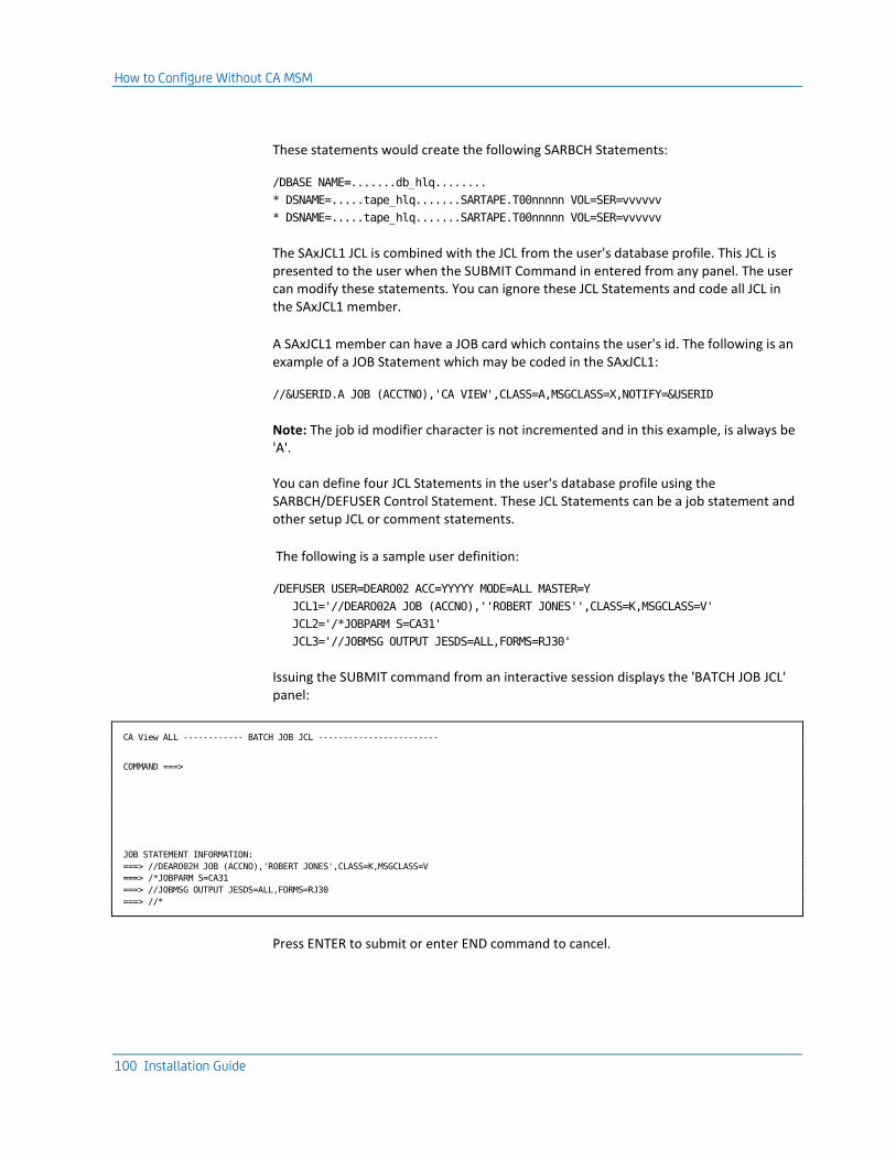
How to Configure Without CA MSM
100 Installation Guide
These statements would create the following SARBCH Statements:
/DBASE NAME=.......db_hlq........
* DSNAME=.....tape_hlq.......SARTAPE.T00nnnnn VOL=SER=vvvvvv
* DSNAME=.....tape_hlq.......SARTAPE.T00nnnnn VOL=SER=vvvvvv
The SAxJCL1 JCL is combined with the JCL from the user's database profile. This JCL is presented to the user when the SUBMIT Command in entered from any panel. The user can modify these statements. You can ignore these JCL Statements and code all JCL in the SAxJCL1 member.
A SAxJCL1 member can have a JOB card which contains the user's id. The following is an example of a JOB Statement which may be coded in the SAxJCL1:
//&USERID.A JOB (ACCTNO),'CA VIEW',CLASS=A,MSGCLASS=X,NOTIFY=&USERID
Note: The job id modifier character is not incremented and in this example, is always be 'A'.
You can define four JCL Statements in the user's database profile using the SARBCH/DEFUSER Control Statement. These JCL Statements can be a job statement and other setup JCL or comment statements.
The following is a sample user definition:
/DEFUSER USER=DEARO02 ACC=YYYYY MODE=ALL MASTER=Y
JCL1='//DEARO02A JOB (ACCNO),''ROBERT JONES'',CLASS=K,MSGCLASS=V'
JCL2='/*JOBPARM S=CA31'
JCL3='//JOBMSG OUTPUT JESDS=ALL,FORMS=RJ30'
Issuing the SUBMIT command from an interactive session displays the 'BATCH JOB JCL' panel:
CA View ALL ------------ BATCH JOB JCL ------------------------
COMMAND ===>
JOB STATEMENT INFORMATION:
===> //DEARO02H JOB (ACCNO),'ROBERT JONES',CLASS=K,MSGCLASS=V
===> /*JOBPARM S=CA31
===> //JOBMSG OUTPUT JESDS=ALL,FORMS=RJ30
===> //*
Press ENTER to submit or enter END command to cancel.

How to Configure Without CA MSM
Chapter 7: Starting Your Product 101
The user can change or delete any of these statements before they are submitted with the JCL from the SAxJCL1 member; the SARBCH Control Cards are generated to fulfill the requested batch functions.
You can bypass the Job Statement submission panel if a standard job statement is coded in the SAxJCL1 member or if the end-user is not allowed to change the job statements saved in the user's profile. The 'BATCH JOB JCL' panel can be bypassed with a simple SARSUBUX exit.
The following sample SARSUBUX statement bypasses the 'BATCH JOB JCL' panel and immediately submits the batch job:
SARSUBUX CSECT
EBCMODE
USING SARSUBUX,15
C 0,=F'12'
BNE RC0
RC4 LA 15,4
BR 14
RC0 SR 15,15
BR 14
END
STEPLIB References
The action you take in this step depends on decisions you made in Step 8: Authorize Program Load Libraries.
The SAxJCL1 skeleton JCL contains a STEPLIB DD statement. This DD statement must be updated if you have not link listed CAI.CVDELOAD or the library you copied the load modules to in the Authorize Program Load Libraries step. If you are running from a linklist library, you can remove the STEPLIB DD statement.
If you have CA Deliver installed into a separate load library, add it to the STEPLIB DD if this library is not in the linklist. You must concatenate the CA Deliver load library after the CA View load library in the STEPLIB statement.
If you have CA Spool installed into a separate load library and want to use the CA View to CA Spool interface, add this library to the STEPLIB DD if this library is not in the linklist. Supply this DD after the CA View and CA Deliver load library DD statements.
Step 6. Load the Online Panels and JCL Library
All users must perform this step. Use this step to choose a language and customize BROWSE and HELP panels.

How to Configure Without CA MSM
102 Installation Guide
Upgrade Considerations
Note: For more information about upgrading and information that applies to this step, see the chapter Migration Information.
Load the panel, message, and skeleton JCL members in the online library to the database.
The OLOAD control statement of the SARDBASE utility is used to load the online library to the database. The online library is defined with the DD statement SAROLIB.
The high-level name of the database must have been previously defined with the NAME control statement (or the PARM parameter of the EXEC JCL statement).
Syntax is as follows:
OLOAD
Note: For more information about how to load the members of the online library to the CA View database, see OLOAD in the SARDBASE Control Statements section in the "Database Utilities" chapter in the Reference Guide.
Sample JCL for this job is provided in member HBRMOLOD of CAI.CVDEJCL.
Choosing Languages for the Panels
You can display the panels in any of several languages in your database. The language panels displayed for a specific end user are determined by the setting of the LANGUAGE parameter on the Batch DEFUSER control statement.
Note: For more information about control statements, see "SARBCH Control Statements" in the Reference Guide.
You can load all of the languages, or only those languages your database uses. Each language requires approximately four cylinders of the database.
The following table shows the data sets containing online panels and their languages:
Language Data Set Name
English CAI.CVDEPENU
French Canadian CAI.CVDEPFRC (optional)
German CAI.CVDEPDEU (optional)
Danish CAI.CVDEPDAN (optional)

How to Configure Without CA MSM
Chapter 7: Starting Your Product 103
Customize BROWSE and HELP Panels
The data sets listed above contain the BROWSE and HELP panels; you can modify them within the following limitations:
■ Constants:
Constants can be modified and their length can be increased or decreased. The new text displays as coded.
■ Variables:
– Most variables can be moved around the screen as long as the original variable names are retained, but be aware that the relative position of some variables is critical.
– The length of a variable can be changed, but be aware that the product pads the value with blanks (or truncates it) to conform to its internal length.
– Any variable can be deleted from a panel.
– An attempt to add a variable to a screen results in the variable name itself appearing on the screen, without interpretation.
Customize Panels for Color and Highlight
The product supports the display of the following colors:
■ Blue
■ Red
■ Pink
■ Green
■ Turquoise
■ Yellow
■ White
The product supports the following highlight attributes:
■ Blink
■ Reverse video
■ Underscore
Note: For these attributes, the colors used must be red, white, blue, or green.
Define color and highlight attributes on the CA Deliver panels according to the rules listed in the IBM manual Dialog Management Guide for ISPF.

How to Configure Without CA MSM
104 Installation Guide
The following hexadecimal characters are reserved and cannot be defined as attribute statements on a panel:
Hex Represents
00 Null character
0E Shift out
0F Shift in
40 Blank
50 Ampersand (&)
Step 7. Load the Model Banner Pages
All users must perform this step.
Upgrade Considerations
For more information about upgrading and information that applies to this step, see the chapter Migration Information.
Upload Considerations
Load the model banner pages to the database.
The BLOAD control statement of the SARDBASE utility is used to load the model banner page library to the database. The model banner page library is defined with the DD statement SARBLIB.
The high-level name of the database must have been previously defined with the NAME control statement (or the PARM parameter of the EXEC JCL statement).
Syntax is as follows:
BLOAD
Note: For more information about how to load the model banner page members to the CA View database, see BLOAD in the SARDBASE Control Statements in the chapter "Database Utilities" in the Reference Guide.
Sample JCL for this job is provided in member HBRMBLOD of CAI.CVDEJCL.

How to Configure Without CA MSM
Chapter 7: Starting Your Product 105
Step 8. (Optional) Add the Microfiche Option
Perform this step if you want CA View to copy your SYSOUT to microfiche automatically; otherwise go to the next step.
If you have not added CAI.CVDEPROC to your procedure library concatenation, add the microfiche start procedure JCL to SYS1.PROCLIB. Sample JCL for this job is provided in member CBRMSMFP of CAI.CVDEPROC.
This JCL contains a STEPLIB DD statement. This DD statement must be updated if you have not link listed CAI.CVDELOAD or the library that you copied the load modules to in the Authorize Program Load Libraries step. If you are running from a linklist library, you can remove the STEPLIB DD statement.
Automatic Microfiche
For more information about how to have CA View automatically produce microfiche, see the following sections in the Reference Guide:
■ Microfiche Processing with SARMFP in the "Configuring" chapter
■ START in the Initialization Parameter Descriptions section in the "Initialization Parameters" chapter
Note: To save the information for a later step, be sure to record the member name of the microfiche procedure next to the START parameter on your Initialization Parameter Worksheet.
Index Parameter
Set the index parameter in the EXEC statement to the high-level name of the CA View database. Use the value next to the NAME parameter on your Initialization Parameter Worksheet.

How to Configure Without CA MSM
106 Installation Guide
SYSOUT and OUT DD Statements
The SYSOUT DD statement defines the SORT messages; this DD statement can be "dummied out" by specifying it as a comment.
The OUT DD statement must define a sequential output file so that it contains microfiche output. Sample file types are as follows:
■ Tape data set processed by an offline microfiche processor
■ Temporary data set passed to a microfiche processor
■ SYSOUT data set for an online microfiche processor
The OUT DD statement DCB attributes can be specified as fixed or variable length. These attributes can be omitted; however, if they are omitted the DCB attributes are copied from the input disk archival generation.
Step 9. (Optional) Set up Job Accounting
Perform this step if you want CA View to capture job accounting data; otherwise go to the next step.
Upgrade Considerations
For more information about upgrading and information that applies to this step, see the chapter Migration Information.
Capture and Format the Accounting File
If you want the started task to capture the job accounting data, see the Job Accounting section in the chapter "Configuring" in the Reference Guide. Also, you may want to review the topic "Formatting the Accounting File" in that chapter.
Sample JCL for this job is provided in member SARINACT of CAI.CVDEJCL.
Note: To save the information for a later step, be sure to record the name of your accounting data set next to the SARACT ddname on your Archival Started Task Worksheet.
Step 10: (Optional) Set Up Backup Tape Tracking
Perform this step if you want the product to use the recovery data set to automatically track tapes used in the backup process; otherwise go to the next step.

How to Configure Without CA MSM
Chapter 7: Starting Your Product 107
Upgrade Considerations
For more information about upgrading and information that applies to this step, see the chapter Migration Information.
Note: We strongly recommend that you use this recovery data set feature.
Define the Recovery Data Set
The started task can automatically track tapes used in the backup process. See the following sections in the Reference Guide:
■ The Recovery Data Set section in the chapter "Configuring"
■ The chapter "Database Backup and Recovery"
Sample JCL for this job is provided in member SARRECV of CAI.CVDEJCL.
Note: To save the information for a later step, be sure to record the name of your recovery data set next to the SARRECV ddname on your Archival Started Task Worksheet.
Step 11: (Optional) Install System Extensions
Perform this step if you want to use CA View extensions for security and automatic report archiving for the data sets or for job accounting; otherwise go to the next step.
Upgrade Considerations
For more information about upgrading and information that applies to this step, see the chapter Migration Information.
Before installing a new version of SARXTD, ensure that the old system extensions have been withdrawn.
Do this by issuing the following command:
S SARXTD,PARM=OFF

How to Configure Without CA MSM
108 Installation Guide
General Considerations for All Users
The system extensions do the following:
■ Allow you to print and archive job output concurrently
■ Provide security over the data sets
■ Capture job accounting information
To add the extensions, if you have not added CAI.CVDEPROC to your procedure library concatenation, add the following start procedure JCL as member CBRMSXTD of SYS1.PROCLIB. Sample JCL for this job is provided in member CBRMSXTD of CAI.CVDEPROC.
//CBRMSXTD PROC CAI=CAI,SUBSYS=@
//IEFPROC EXEC PGM=SARXTD,
// TIME=NOLIMIT,REGION=0M
//STEPLIB DD DISP=SHR,DSN=&CAI..CVDELOAD
//SUBSYS&SUBSYS DD DUMMY
//NOTERM DD DUMMY
//NOCONF DD DUMMY
//SYSUDUMP DD SYSOUT=X
//PRINT DD SYSOUT=X
//SARACT DD DISP=SHR,DSN=&CAI..SARACT
Note: Use the value next to the SARACT ddname on your Archival Started Task Worksheet for your SARACT data set name.
Library Authorization
The JCL for this job contains a STEPLIB DD statement. This DD statement must be updated if you have not link listed CAI.CVDELOAD, or the library you copied the load modules to in the Authorize Program Load Libraries step. If you are running from a linklist library, you can remove the STEPLIB DD statement.
Data Set Security and Automatic Report Archival
The parameters passed to the program through the PARM field on the EXEC statement apply to data set security and automatic report archival.
Note: For more information, see Systems Extensions (SARXTD) in the "Configuring" chapter in the Reference Guide.

How to Configure Without CA MSM
Chapter 7: Starting Your Product 109
Job Accounting
If you want job accounting through CA View extensions, do the following:
■ Include the SARACT DD statement
Note: For more information about job accounting, see Job Accounting in the chapter "Configuring" in the Reference Guide.
■ Use the value next to the SARACT ddname on your Archival Started Task Worksheet for your SARACT data set name.
If you do not want job accounting, do not include the SARACT DD statement.
Step 12: (Optional) Exceptional Condition Checking
Perform this step if you want the product to check for exceptional conditions; otherwise go to the next step.
Upgrade Considerations
For more information about upgrading and information that applies to this step, see the chapter Migration Information.
General Considerations for All Users
CA View records job-end condition codes and stores them with the SYSOUT. Certain CA View features (such as the Expanded Retention Option and the XPRINT initialization parameters) use these condition codes to determine processing. The product provides the following system default exceptional condition specifications:
■ Non-zero condition code
■ Data set not deleted
■ Data set not cataloged
■ Data set not recataloged
■ Data set not uncataloged
■ JCL error
■ Operator cancel in allocation recovery
■ System ABEND
■ User ABEND
■ User defined character strings
If these defaults are not correct for your system, proceed with this step; otherwise go to the next step.

How to Configure Without CA MSM
110 Installation Guide
Creating Exceptional Condition Statements
The product allows you to create exceptional condition statements.
Note: For more information about exceptional condition, see Exceptional Condition Checking in the chapter "Archival" in the Reference Guide.
The DD statement SARXCTAB in your SARSTC startup JCL and SARFSS JCL points to the file that contains your exceptional condition code checking statements.
Note: To save the information for a later step, be sure to enter the name of your exceptional condition statements data set next to the SARXCTAB ddname on your Archival Started Task Worksheet.
Step 13: (Optional) Replace or Modify User Exits
Perform this step if you want to replace or modify any of the default user exits; otherwise go to the next step.
Upgrade Considerations
For more information about upgrading and information that applies to this step, see the chapter Migration Information.
For each user exit that you have tailored in previous releases, update the new CA View skeleton version and assemble it using the macros in CAI.CVDEMAC. See the comments in the sample exits before updating them.
General Considerations for All Users
The following table lists the user exits and the CAIOPTN members that you can use to install them.
Note: For more information about user exits, see the chapter "User Exits" in the Reference Guide.
User Exit CVDEJCL Member
CVDEJCL Non-SMP
Function
SARACFUX BRMSACFX BRMJACFX ACIF archival task exit
SARACTUX BRMSACTX BRMJACTX Job accounting
SARARAUX BRMSARAX BRMJARAX Automatic report archival
SARATHUX BRMSATHX BRMJATHX Authorization
SARBKTUX BRMSBKTX BRMJBKTX Backup cycle

How to Configure Without CA MSM
Chapter 7: Starting Your Product 111
User Exit CVDEJCL Member
CVDEJCL Non-SMP
Function
SARDSTUX BRMSDSTX BRMJDSTX Reprint destinations
SARD00UX BRMSD00X BRMJD00X Migrate Cycle exit
SARD03UX BRMSD03X BRMJD03X Secondary Storage Drive exit
SARD05UX BRMSD05X BRMJD05X Secondary Storage Drive exit
SAREASUX BRMSEASX BRMJEASX EAS for tape and robotics exit
SARFVCUX BRMSFVCX BRMJFVCX View collector archival task exit
SARJS2UX BRMSJS2X BRMJJS2X JES control block mapping
SARMFPUX BRMSMFPX BRMJMFPX Microfiche
SAROMSUX BRMSOMSX BRMJOMSX Online management system
SARPACUX BRMSPACX BRMJPACX SARPAC tape consolidation
SARPAMUX BRMSPAMX BRMJPAMX SARPAM Service Routine exit
SARPRFUX BRMSPRFX BRMJPRFX User profile
SARPRTUX BRMSPRTX BRMJPRTX Print
SARSECUX BRMSSECX BRMJSECX Security
SARSMFUX BRMSSMFX BRMJSMFX SMF processing
SARSPFUX BRMSSPFX BRMJSPFX Selection list formatting
SARSRQUX BRMSSRQX BRMJSRQX Selection request
SARSTCUX BRMSSTCX BRMJSTCX Archival task
SARSUBUX BRMSSUBX BRMJSUBX Job submission
SARTPOUX BRMSTPOX BRMJTPOX Tape creation VOLSER exit
SARUNLUX BRMSUNLX BRMJUNLX Selective Unload User exit
SARUSxUX BRMSUSxX BRMJUSxX User ID determination
SARXCTUX BRMSXCTX BRMJXCTX Exceptional condition checking

How to Configure Without CA MSM
112 Installation Guide
Note: Sample JCL is provided to assist with the installation of most CA View user exits in two formats. One sample format provides JCL for SMP/E-controlled USERMOD installation, and one sample format provides JCL to install outside of SMP.
The non-SMP/E samples have been provided in this release to help facilitate improved management of multiple sets of target libraries that have been deployed on more than a single LPAR and have different configuration criteria. To safely manage user exits outside of SMP/E, link the exits into a separate, independent load library that can be link-listed or concatenated before the CA View product load library. We recommend that you test the product before customizing exits.
For more information about User Exits, see the Reference Guide.
Step 14: (Optional) Set up for Multiple CPUs
Important! Perform this step only if your system is running multiple CPUs.
Upgrade Considerations
For more information about upgrading and information that applies to this step, see the chapter Migration Information.
Be aware of the following:
■ No active tasks must be running that are pointing to the CVDELOAD and database that are being upgraded.
If a CA View database is accessed from multiple CPUs or LPARs, all PROCs, JCL, CLISTS, and so forth that access the database must also be upgraded.
Define ENQs to the System Integrity Products
If you use a system integrity product, make the required changes to accommodate the new CA View database. RESERVES are issued against both the first index extent and the first data extent; therefore, a review of local configurations is required.
The product issues ENQs and RESERVEs as necessary to maintain the integrity of its data sets. The primary ENQ (QNAME=SARSTC) is used by the archival task to ensure that only one archival task starts using a specific database. The ENQ is defined as SYSTEMS which will be propagated to all LPARs in a PLEX. This queue name need not be defined to a system integrity product. A secondary ENQ (QNAME=SARPAC) is used by the tape consolidation utility SARPAC. This is also defined as SYSTEMS and need not be defined to a system integrity product.

How to Configure Without CA MSM
Chapter 7: Starting Your Product 113
The RESERVE issued by CA View is normally short-lived but causes deadlock conditions unless properly defined. Convert them to global enqueues; however, if your environment dictates, the reserves need not be converted. If a database's first index extent AND the first data extent are on dedicated volumes with no other data sets, you do not need to convert RESERVES to global enqueues.
Using RESERVE and ENQ
The following table shows how CA View uses ENQ and RESERVE:
QNAME Type Description Integrity Product Control
SARSTC ENQ Restricts the CA View database to only one archival task
NO
SARPAC ENQ Restricts the CA View SARPAC utility to only one task at a time.
NO
SARACT RESERVE Serializes the updating of the CA View accounting file
YES (NO if environment dictates)
SARUPD RESERVE Serializes the updating of the CA View database and index
YES (NO if environment dictates)
Database Extent Considerations
In a multiple CPU environment, it is possible to have processes in each system image accessing a database extent.
To minimize contention, we recommend that you place each database extent on a dedicated volume. Where possible, the size of the volume must match the size of the database extent. This allows each extent to be accessed by its own server (device address) and prevents I/O for multiple extents from queuing on the same device address, which can happen if multiple database extents are allocated on the same device.
Place the first extent of the index and the database on dedicated volumes because the RESERVE processing uses the data set name and volume of the first extent to serialize all accesses. If multiple database or index extents are on the same volume, then RESERVE can prevent access to the other database or index extents.

How to Configure Without CA MSM
114 Installation Guide
Step 15: (Optional) Install Optional Online Interfaces
Perform this step if you want to install any of the optional online interfaces; otherwise go to the next step.
Note: For more information about installing optional online interfaces, see the chapter "Installing Online Interfaces."
Step 16: (Optional) Install Optional Features
Perform this step if you want to install any of the optional features; otherwise go to the next step. For more information about installing optional features, see the chapter "Installing Features."
Upgrade Considerations
For more information about upgrading and information that applies to this step, see the chapter Migration Information.
Review the chapter "Installing Features" and ensure that any STEPLIBs in your JCL reference the new CAI.CVDELOAD and that you use the new ERO parameters.
Step 17: (Optional) Download the EMC Centera API for CA View
The CA View Option for EMC Centera enables you to migrate and retrieve reports to/from a Centera disk cluster to the CA View database for viewing or printing.
The EMC Centera API is part of a separate, chargeable option for CA View, which is distributed on a separate cartridge that contains all the data required for the installation.
Sample JCL for downloading the EMC Centera API load library from the cartridge is provided in member HBRMCENT of CAI.CVDEJCL. Customize the JCL member to reflect a valid JOB statement, data set names, and volume serial numbers.
Note: For more information about the EMC Centera Option, see the chapter "EMC Centera Disk Option" in the Reference Guide.
Step 18: Add the Archival Task Start Procedure
All users must perform this step.

How to Configure Without CA MSM
Chapter 7: Starting Your Product 115
Upgrade Considerations
For more information about upgrading and information that applies to this step, see the chapter Migration Information.
General Considerations for All Users
All CA Deliver started tasks (RMOSTC) that are writing to a Version 12.0 CA View database must use the CA View Version 12.0 CVDELOAD load library.
Note: The CA View databases referenced by those CA Deliver started tasks can be at release level r11, r11.5, r11.6, r11.7, or Version 12.0.
SARSTC Startup Procedure
If CAI.CVDEPROC is not in your system procedure library concatenation, add the archival task startup procedure to SYS1.PROCLIB. Sample JCL statements for this job are in member CBRMSSTC of CAI.CVDEPROC.
//CBRMSSTC PROC CAI=CAI,DB=VIEW.SYSTEM1,OPT=CLEAN
//IEFPROC EXEC PGM=SARSTC,PARM='&DB,&OPT',
// TIME=NOLIMIT,REGION=0M
//STEPLIB DD DISP=SHR,DSN=&CAI..CVDELOAD
//*
//* OPTIONAL AND FEATURE DEPENDENT DD STATEMENTS:
//*
//SARACT DD DISP=SHR,DSN=&CAI..SARACT
//SARRECV DD DISP=SHR,DSN=&CAI..SARRECV
//SARXCTAB DD DISP=SHR,DSN=&CAI..CVDEOPTN(PARMXCT)
//SARPATAB DD DISP=SHR,DSN=&CAI..CVDEOPTN(PARMERO)
//SARBKLST DD SYSOUT=X,DCB=BLKSIZE=1330
//SARDRLST DD SYSOUT=X,DCB=BLKSIZE=1330
//SARD2LST DD SYSOUT=X,DCB=BLKSIZE=1330
//SYSPRINT DD SYSOUT=X
//SYSOUT DD SYSOUT=X
//SYSUDUMP DD SYSOUT=X
Library Authorization
The JCL for this job contains a STEPLIB DD statement. This DD statement must be updated if you have not link listed CAI.CVDELOAD, or the library you copied the load modules to in the Authorize Program Load Libraries step. If you are running from a linklist library, you can remove the STEPLIB DD statement.

How to Configure Without CA MSM
116 Installation Guide
Index Name (Database High Level Qualifier)
Set the DB symbolic on the PROC statement to the high-level name of the database.
Use the value next to the NAME parameter on your Initialization Parameter Worksheet.
The Backup List Report
The Backup List report shows SYSOUTs that were backed up to tape, with their corresponding tape numbers.
To create this report, include the SARBKLST DD statement.
The DR Tape Backup List Report
The DR Tape Backup List report shows SYSOUTs that were backed up to the DR tape, with their corresponding tape numbers.
To create this report, include the SARDRLST DD statement.
The Optical Migration Report
The Optical Migration report (secondary disk) shows SYSOUTs that were backed up to optical disk.
To create this report, include the SARD2LST DD statement.
Optional Functions
Several of the optional functions need DD statements in the started task JCL (SARSTC).
If you installed an optional function, include the DD statement with the appropriate data set name (from your Archival Started Task Worksheet) in SARSTC.
Note: Do not include DD statements for functions you did not install.
Step 19: Use SARINIT to Set the Final Initialization Parameter Values
All users must perform this step.
Upgrade Considerations
For more information about upgrading and information that applies to this step, see the chapter Migration Information.

Post-Installation Considerations
Chapter 7: Starting Your Product 117
General Considerations for All Users
The SARINIT program is used to inspect, set, or change database initialization parameters. For complete instructions and a discussion of the parameters available, see the chapter "Initialization Parameters" in the Reference Guide.
Review the Initialization Parameter Worksheet
Review all of the parameters on your Initialization Parameter Worksheet. Verify that all options have been appropriately set.
Note: Any parameter that you do not modify is set to its default value.
Run SARINIT
Use the following procedure to run SARINIT. Sample JCL for this job is provided in member SARINIT of CAI.CVDEJCL.
1. Create the SARINIT control statements using the Initialization Parameter Worksheet in the appendix "Installation Worksheets."
2. Run SARINIT.
3. Save this JCL and control statements.
Note: You can run SARINIT again to change particular options.
Step 20. (Optional) Customize and Configure CA DRAS
Perform this step if you have installed the CA DRAS component to enable cooperative viewing with CA Output Management Web Viewer.
Note: For information about customizing and configuring CA DRAS, see the CA DRAS Operations Guide.
Post-Installation Considerations
Now that you have successfully installed CA View, consider the following:
■ For information about shutting down CA View, see the User Guide.


Chapter 8: Migration Information 119
Chapter 8: Migration Information
This section contains the following topics:
Upgrading from Release 11.7, r11.6, r11.5, and r11 (see page 119)
This section contains the information you need to upgrade to CA View Version 12.0 from CA View Releases r11.7, r11.6, r11.5, or r11.
For an overview of the changes in this release, see the Release Notes.
Upgrading from Release 11.7, r11.6, r11.5, and r11
These instructions are for sites that want to upgrade to CA View Version 12.0 from CA View Release r11.7, r11.6, r11.5, or r11; they consist of the original steps and a series of modifications.
To upgrade to Version12.0, use the steps in the following chapters:
■ "Installing Your Product Using CA MSM," "Installing Your Product From Pax-Enhanced Electronic Software Delivery," or "Installing Your Product From Tape"
■ "Starting Your Product"
■ "Installing Online Interfaces,"
■ "Installing Features"
Modify the steps according to the supplementary instructions in the tables in the following sections:
■ Installation Steps to Upgrade to Version12.0
■ Configuration Steps to Upgrade to Version12.0
Existing Release r11.7, r11.6, r11.5, or r11 users will install the product in almost the same way as new users with one exception; instead of creating a database you version your existing database. This process updates several records in the database and executes in a few minutes.
Note: To revert to Release r11.7, r11.6, or r11.5, see the chapter Reverting to a Prior Installation.

Upgrading from Release 11.7, r11.6, r11.5, and r11
120 Installation Guide
Installation Steps to Upgrade to Version12.0
To upgrade to Version 12.0, perform each installation step exactly as presented in either of the three "Installation" chapters unless the step has upgrade instructions in the table that follows.
The Step column lists the step and the Upgrade Instructions column explains what you must do if the step needs to be modified or replaced.
Installation Step
Supplementary Upgrade Instructions
Step BRM1ALL
Comment out or delete the allocations for the target libraries that exist.
Note: Beginning with release r11, to help simplify installations and upgrades, the foreign language panel FMIDs have been incorporated into the CA View base FMID. This change requires that all four panel libraries exist or the apply step will fail.
Also, it is likely that any existing panel libraries must be enlarged before you run the Apply step. See the Hardware Requirements section to determine the amount of space required for these libraries and adjust accordingly. If you are upgrading from r11.7, and the panel libraries are sufficiently allocated, skip this step.
Step BRM2CSI
Comment out or delete the allocations for any libraries that already exist. Comment out or delete the step that creates the CSI. Change all ADD statements to REP statements. If you are upgrading from r11.7, skip this step.
Note: The default middle level qualifier name of the SMP/E CSI has been removed beginning with release r11.6. If upgrading from a previous release, ensure that the correct, complete name of your CSI is specified in the PARM= on the execute card.
Steps BRM3RECD or BRM3RECT, BRM4APP, BRM5ACC
No supplementary instructions.
However, be aware that the default middle level qualifier name of the SMP/E CSI has been removed beginning with release r11.6. If upgrading from a previous release, ensure that the correct, complete name of your CSI is specified in the PARM= on the execute card.

Upgrading from Release 11.7, r11.6, r11.5, and r11
Chapter 8: Migration Information 121
Configuration Steps to Upgrade to Version 12.0 without CA MSM
To upgrade to Version 12.0, perform each configuration step exactly as presented in the Starting Your Product chapter unless the step has upgrade instructions in the table that follows.
The Step column lists the step and the Upgrade Instructions column explains what you must do if the step needs to be modified or replaced.
Configuration Step
Supplementary Upgrade Instructions
Step 1-3 No supplementary instructions.
Step 4 Optionally set the version of your database up to Version 12.0. Version 12.0 provides full compatibility with release r11, r11.5, r11.6, and r11.7 databases. If you want to utilize specific Version12.0 features, upgrade the database to Version 12.0.
Note: If you do not want to upgrade your release r11, r11.5, r11.6, or r11.7 databases, skip this step.
This step replaces the Create the Database step in the chapter "Starting Your Product."
Instead of creating a CA View database, use the VERSION control statement of the SARDBASE utility to version your database to Version 12.0. This procedure executes in a few minutes.
The high-level name of the database must have been previously defined with the NAME control statement (or the PARM parameter of the EXEC JCL statement) for the SARDBASE utility. The format of the VERSION control statement is:
Version 12.0
Sample JCL to version the database is provided in member
HBRMVERS in CAI.CVDEJCL
For more information, see the SARDBASE utility in the chapter "Database Utilities" in the Reference Guide.
Note: Save your initialization parameter settings; some parameter settings have been added or eliminated in Version 12.0, but you may need the original settings if you have to revert to release r11.5, r11.6, or r11.7.
Step 5 No supplementary instructions

Upgrading from Release 11.7, r11.6, r11.5, and r11
122 Installation Guide
Step 6 Load Online Panels and JCL Library
If online panel members were customized in release r11.x, copy those members to the appropriate Version 12.0 online library.
Follow the instructions in this step in the "Starting Your Product" chapter and load the online panels for each language you are using to the database. Because some online panels have changed, you must OLOAD the new panels.
Note: Only perform the OLOAD of the new panels if the database has been versioned to Version 12.0.
Step 7 Load the Model Banner Pages
If model banner page members were customized or added in release 11.x, copy those members to the Version 12.0 model banner page library.
Follow the instructions in this step in the "Starting Your Product" chapter and load the model banner panels to the database.
Step 8 Add the Microfiche Option (Optional)
Follow the instructions in this step in the "Starting Your Product" chapter. If you plan to use microfiche, add or adjust the start procedure in the PROCLIB.
Step 9 Set up Job Accounting (Optional)
Skip this step if you want to continue to capture job accounting data in the same way you captured it in the r11.x releases. Otherwise, follow the instructions in this step in the "Starting Your Product" chapter.
Step 10 Set up Backup Tape Tracking (Optional)
Skip this step if you want to continue to automatically track backup tapes the same way you used it in the r11.x releases. Otherwise, follow the instructions in this step in the "Starting Your Product" chapter.
Step 11 Install System Extensions (Optional)
Follow the instructions in this step in the "Starting Your Product" chapter. If you use system extensions, add or adjust the start procedure in the PROCLIB.
Before installing a new version of SARXTD, be sure that the old system extensions have been withdrawn.
Do this by issuing the following command:
S SARXTD,PARM=OFF
Include the system extensions parameter in the started task JCL. Be sure that the system extensions JCL procedure is pointing to the new version of CVDELOAD through the STEPLIB statement.
Note: If the CA View load modules were copied to your linklist library, remove the STEPLIB statement in the system extensions Proc.

Upgrading from Release 11.7, r11.6, r11.5, and r11
Chapter 8: Migration Information 123
Step 12 Exceptional Condition Checking (Optional)
Skip this step if you want to continue to use exceptional condition checking the same way you used it in the r11.x releases. Otherwise, follow the instructions in this step in the "Starting Your Product" chapter to modify the system defaults for exceptional condition checking.
Step 13 Replace or Modify User Exits (Optional)
Perform this step if you modified any of the CA View user exits; otherwise, go to the next step.
For each user exit that you have tailored in r11.x releases, copy your changes to the new CA View skeleton version and assemble it.
Sample JCL is provided to assist with the installation of most CA View user exits in two formats. One sample format provides JCL for SMP/E-controlled USERMOD installation, and one sample format provides JCL to install outside of SMP.
The non-SMP/E samples have been provided in this release to help facilitate improved management of multiple sets of target libraries that have been deployed on more than a single LPAR and have different configuration criteria. To safely manage user exits outside of SMP/E, link the exits into a separate, independent load library that can be link-listed or concatenated before the CA View product load library.
Save a copy of your user exits in case you need to revert to the previous release.
The SARFVCUX and SARSTCUX user exits are now called with a new entry code 12 starting with r11.6. If you are tailoring these user exits, be sure that your user exit(s) correctly handle this new entry code. If your user exit code performs a simple check for entry code 4 and assumes that a higher value is the close call, an additional check may have to be added for entry code 12. In most cases, the entry code 12 call can be ignored by exiting from the user exit.
If desired, the original sysout records can be monitored or altered through the entry code 12 call.
For more information about user exits, see the "User Exits" chapter in the Reference Guide.

Upgrading from Release 11.7, r11.6, r11.5, and r11
124 Installation Guide
Step 14 Set Up for Multiple CPUs
Review the instructions in this step in the "Starting Your Product" chapter. Verify that ENQs and RESERVEs are defined sufficiently to maintain integrity of the data sets.
Be aware of the following:
■ No active tasks must be running that are pointing to the CVDELOAD and database that are being upgraded.
■ If multiple versions of CA View are running on multiple CPUs and share the database, all PROCs, JCL, CLISTS, and so forth, that access a given CA View database must also be upgraded.
Step 15 No supplementary instructions
Step 16 Install Optional Features (Optional)
Verify that the LMP key has been supplied for each feature that you want to install; see the Enter the LMP Code step in the "Starting Your Product" chapter, then follow the installation instructions in the Installing Features section.
You should not have to make any changes in your current use of those programs.
Use a new CVDELOAD and new ERO parameters.
There has been a minor change to cross-memory (one of the CA View optional features): the cross-memory program name was changed to EC0DRV to permit concurrent execution of the releases.
For more information, see Installing Cross-Memory Services (XMS) in the Installing Online Interfaces section
Step 17 Download the EMC Centera API for CA View (Optional)
Follow the instructions in the chapter "EMC Centera Disk Option" in the Reference Guide to download and configure the EMC Centera Disk Option.
Step 18 Add the Archival Task Start Procedure
Follow the instructions in the Installation chapter you are using and add or adjust the archival start procedure in the PROCLIB. Ensure that STEPLIB points to the new CAI.CVDELOAD load library.
You may want to add the following statements, if you do not already have them:
■ The SARBKLST DD statement provides information about reports backed up to tape, reports deleted from the database by the backup cycle, and uncataloged tapes.
■ The SARD2LST DD statement provides information about reports backed up to the DR tape.
■ The SARDRLST DD statement provides information about optical migration.

Upgrading from Release 11.7, r11.6, r11.5, and r11
Chapter 8: Migration Information 125
Step 19 Use SARINIT to Set the Final Initialization Parameter Values
Follow the instructions in this step in the Starting Your Product chapter. Some initialization parameters have been added, changed, or eliminated in Version 12.0. Be sure to review the initialization parameters in the "Initialization Parameters" chapter in the Reference Guide.
For more information about all initialization parameter changes, see the Release Notes.
Note: Be sure to review any changes made to the FEATURE initialization parameter for this release and adjust your values removing any feature codes that have been deactivated.
Save a copy of your initialization parameters in case you want to revert to a previous release.
Step 20 Customize and Configure CA DRAS (Optional)
Perform this step if you have installed the CA DRAS component to enable cooperative viewing with CA Output Management Web Viewer.
For more information about customizing and configuring CA DRAS, see the CA DRAS Operations Guide.


Chapter 9: Reverting to a Prior Installation 127
Chapter 9: Reverting to a Prior Installation
This section provides the instructions to use to revert to Releases r11.7, r11.6, or r11.5.
This section contains the following topics:
Revert to Release 11.7 (see page 127) Revert to r11.6 (see page 128) Revert to r11.5 (see page 129)
Revert to Release 11.7
You can revert to CA View Release r11.7, if required.
Follow these steps:
1. Use the CA View Version 12.0 SARDBASE utility to set the version of your CA View database back to a CA View Release r11.7 database. The format of the VERSION control statement is:
VERSION 11.7
Note: If your CA View database is currently versioned to release level Release r11.7 or earlier, skip steps 1 and 2.
2. Use the CA View Release r11.7 release SARDBASE utility to OLOAD the Release r11.7 online panel library into your database.
3. Use the CA View Release r11.7 release SARDBASE utility to BLOAD the Release r11.7 banner page library to your database.
4. If you modified any of the CA View user exits, revert to your Release r11.7 versions of the exits.
5. Change your JCL, Procs, and started task JCL to point to the Release r11.7 libraries.
6. If the Version 12.0 load library was link listed, revert to the Release r11.7 link listed library.

Revert to r11.6
128 Installation Guide
Revert to r11.6
If you decide to revert to CA View r11.6, follow these steps:
1. Use the CA View Version 12.0 SARDBASE utility to set the version of your CA View database back to a CA View r11.6 database. The format of the VERSION control statement is:
VERSION 11.6
Note: If your CA View database is currently versioned to release level r11.6 or earlier, skip steps 1 and 2.
2. Use the CA View r11.6 release SARDBASE utility to OLOAD the r11.6 online panel library into your database.
3. Use the CA View r11.6 release SARDBASE utility to BLOAD the r11.6 banner page library to your database.
4. If you modified any of the CA View user exits, revert to your r11.6 versions of the exits.
5. Change your JCL, Procs, and started task JCL to point to the r11.6 libraries.
6. If the Version 12.0 load library was link listed, revert to the r11.6 link listed library.
7. Ensure that PTF RO28310 is applied to release r11.6; this ensures that Release r11.7 and Version 12.0 tapes can be read by release r11.6.

Revert to r11.5
Chapter 9: Reverting to a Prior Installation 129
Revert to r11.5
If you decide to revert to CA View r11.5, follow these steps:
1. Use the CA View Version 12.0 SARDBASE utility to set the version of your CA View database back to a CA View r11.5 database. The format of the VERSION control statement is:
VERSION 11.5
Note: If your CA View database is currently versioned to release level r11.5 or earlier, skip steps 1 and 2.
2. Use the CA View r11.5 release SARDBASE utility to OLOAD the r11.5 online panel library into your database.
3. Use the CA View r11.5 release SARDBASE utility to BLOAD the r11.5 banner page library to your database.
4. If you modified any of the CA View user exits, revert to your r11.5 versions of the exits.
5. Change your JCL, Procs, and started task JCL to point to the r11.5 libraries.
6. If the Version 12.0 load library was link listed, revert to the r11.5 link listed library.
7. Ensure that PTF RO17278 and PTF RO31552 are applied to r11.5; this ensures that r11.6, Release r11.7, and Version 12.0 tapes can be read by release r11.5.
Note: If the database contains encrypted data or large format data sets (data sets allocated with more than 4369 cylinders), unload the database and reload to a new database before reverting to r11.5. Allocate the data sets for the new database with 4369 cylinders or less. Before unloading the database, be sure that the ENCRYPT initialization parameter is set to NO and SARPAC any backup tapes and DR tapes that contain encrypted data.


Chapter 10: Installing the Online Interfaces 131
Chapter 10: Installing the Online Interfaces
This section contains the following topics:
How to Complete Configuration of the XMS Online Interfaces with CA MSM (see page 131) How to Configure the Online Interfaces Without CA MSM (see page 160)
How to Complete Configuration of the XMS Online Interfaces with CA MSM
These steps are configured automatically by the EBC Common Component Configuration Option.
■ XMS Startup PROC
■ Initialization Parameter Statements
■ Modify, Assemble and Link of the EC0XMCTR Module
■ Definition of Transactions and Programs to CICS.
The EBC Common Component Configuration Option includes several external tasks that are required to complete the configuration.
How to Complete Configuration of the XMS Online Interfaces with CA MSM
132 Installation Guide
Define Security Requirements
You can define security requirements for CA Top Secret (eTrust CA Top Secret).
Follow these steps:
1. Rename the existing facility in the facility matrix table if you do not have a facility defined for VIEWXMS.
user1=NAME=VIEWXMS
2. Verify that the correct PGMname is defined for the new facility, where PGMname is either the first three characters or all the eight characters of the program name that is going to make security calls (EC0 or EC0DRV).
3. Create region ACID for the facility.
TSS CRE(viewxms)pass(nopw,0) type(user) dept(dept) mastfac(viewxms NODSNCHK
NORESCHK NOVOLCHK NOLCFCHK NOSUBCHK
4. Define the VIEWXMS STC to the TSS STC record.
TSS ADDTO(STC) PROCNAME(viewxms) ACID(viewxms)
5. Give access to the ACIDs required to sign on to this facility.
TSS ADD(ACID) FAC(viewxms)
Install the ISPF/Cross-Memory Online Retrieval Option
The ISPF/Cross-Memory Online Retrieval Option runs under IBM's ISPF for z/OS Version 3.0 and higher.
Important! This interface requires Cross-memory services to be already installed. For more information, see Install Cross-Memory Services in this chapter.
Note: In the JCL for the cross-memory services task, the parameter XMSSUB must be set to YES.

How to Complete Configuration of the XMS Online Interfaces with CA MSM
Chapter 10: Installing the Online Interfaces 133
Installation Steps
The following steps are required to install the ISPF/cross-memory online retrieval option. Each step is explained in detail later in the sections that follow.
1. (Optional) Add STEPLIB DD Statements to the TSO LOGON procedures if the load modules were not copied to a linklist library.
2. Add the panel and command table libraries to the TSO logon procedures. (For ISPF only, not for SPF.)
3. (Optional) Modify an SPF selection menu to select the online retrieval feature.
Note: For more information about the ISPF/cross memory online retrieval option, see the chapter "Online Interface Administration" in the Reference Guide.
(Optional) Step 1: Add STEPLIB DD Statements to the TSO LOGON Procedures
The action you take in this step depends on what you did during the base-product installation—specifically, did you:
■ Authorize the program load library
or
■ Copy the modules to a system authorized library
If the CA View load modules were not copied to one of the libraries in the linklist, proceed with this step; otherwise go to the next step.
For this interface, the libraries do not have to be APF authorized. Authorization is provided in the cross-memory installation. Multiple versions of this online interface can coexist in one TSO library concatenation.
Do one of the following:
■ Add a STEPLIB DD statement for the library that contains the load modules to the LOGON procedures for those TSO users who are going to use the ISPF/cross-memory online retrieval option.
■ Provide the load library that uses the ISPF LIBDEF facility.
Note: If multiple versions are going to be running simultaneously, or you also want to run a previous version of SARSPF or SARTSO, concatenate the load library you want SARSPF or SARTSO to use first.
More information:
Step 5. Modify the Skeleton JCL (see page 97)

How to Complete Configuration of the XMS Online Interfaces with CA MSM
134 Installation Guide
Step 2: Add Panel and Command Table Libraries to TSO Logon
If you are going to run CA View under ISPF, proceed with this step. For Version 3 or higher, both the command table library and the panel library are used.
To add panel and command table libraries to the TSO LOGON procedure:
■ Concatenate the command table library CAI.CVDETBL0 to DD statement ISPTLIB.
■ Concatenate the panel library CAI.CVDEPNL0 to DD statement ISPPLIB.
Note: If you also plan to use SARSPF (the ISPF interface), and multiple versions of CA View, concatenate CAI.CVDETBL0 first. Use the CAI.CVDETBL0 from the most current release.
Step 3: (Optional) Modify an ISPF Selection Menu to Select Online Retrieval
If you want to add a selection code to one of the ISPF selection menus for the online retrieval feature, proceed with this step; otherwise, your ISPF detailed instructions are complete.
Note: If you add a selection code, you can select the online retrieval feature in the same way you select other ISPF options.
Use the value next to the NAME parameter on your Initialization Parameter Worksheet for PARM(high-level-database-name).
Use the values in this table for either SPF or ISPF.
Type Selection Code is Defined As
ISPF (all versions) 'PGM(EC0XMSPF) PARM(high-level-database-name) NEWAPPL(SAR)'
SPF 'PGM(EC0XMSPF) PARM(high-level-database-name)'
Panel Libraries
The names of the panel libraries vary from site to site and for the different releases of ISPF. These panel libraries are allocated to the ISPPLIB DD statement under TSO.

How to Complete Configuration of the XMS Online Interfaces with CA MSM
Chapter 10: Installing the Online Interfaces 135
Be aware that some installations do not allow direct modifications of IBM panels and libraries. In this case, you can place the modified panels in user or site-specific libraries and concatenate them ahead of the IBM libraries.
Ask your system administrator for the specific ISPF panel library that applies to your site and contains the panel ISR@PRIM.
Note: The selection menus shown in the following examples are part of the program products SPF and ISPF, and are copyrighted by IBM.
Example 1
The following example shows you how to add selection code R to the primary option menu ISR@PRIM for ISPF. The bright, offset text identifies the inserted lines.
%----------------------- ISPF/PDF PRIMARY OPTION MENU --------------------
%OPTION ===>_ZCMD +
% +USERID - &ZUSER
% 0 +ISPF PARMS - Specify terminal and user parameters +TIME - &ZTIME
% 1 +BROWSE - Display source data or output listings +TERMINAL - &ZTERM
% 2 +EDIT - Create or change source data +PF KEYS - &ZKEYS
% 3 +UTILITIES - Perform utility functions
% 4 +FOREGROUND - Invoke language processors in foreground
% 5 +BATCH - Submit job for language processing
% 6 +COMMAND - Enter TSO Command, CLIST, or REXX exec
% 7 +DIALOG TEST - Perform dialog testing
% 8 +LM UTILITIES- Perform library administrator utility functions
% C +CHANGES - Display summary of changes for this release
% R +SARSPF - Retrieve SYSOUT
% T +TUTORIAL - Display information about ISPF/PDF
% X +EXIT - Terminate ISPF using log and list defaults
%
+Enter%END+command to terminate ISPF.
)INIT
.HELP = ISR00003
&ZPRIM = YES /* ALWAYS A PRIMARY OPTION MENU */
&ZHTOP = ISR00003 /* TUTORIAL TABLE OF CONTENTS */
&ZHINDEX = ISR91000 /* TUTORIAL INDEX - 1ST PAGE */
)PROC
&ZSEL = TRANS( TRUNC (&ZCMD,'.')
0,'PANEL(ISPOPTA)'
1,'PGM(ISRBRO) PARM(ISRBRO01)'
2,'PGM(ISREDIT) PARM(P,ISREDM01)'
3,'PANEL(ISRUTIL)'
4,'PANEL(ISRFPA)'
5,'PGM(ISRJB1) PARM(ISRJPA) NOCHECK'
6,'PGM(ISRPTC)'
7,'PGM(ISPYXDR) PARM(ISR) NOCHECK'
8,'PANEL(ISRLPRIM)'
C,'PGM(ISPTUTOR) PARM(ISR00005)'
R,'PGM(EC0XMSPF) PARM(VIEW.SYSTEM1) NEWAPPL(SAR)'
T,'PGM(ISPTUTOR) PARM(ISR00000)'
' ',' '
X,'EXIT'
*,'?' )
&ZTRAIL = .TRAIL
)END

How to Complete Configuration of the XMS Online Interfaces with CA MSM
136 Installation Guide
Note:
■ NEWAPPL(SAR) is required and must be specified as shown previously in this section.
This parameter is used with the command table library concatenation from Step 3 of the ISPF Installation Instructions.
■ NEWAPPL(SAR) allows CA View to correctly interpret commands and program function key invocation.
If this parameter is not specified, certain PF keys such as the scroll keys may not function.
Example 2
The following example shows you how to add selection code R to the primary option menu ISP@PRIM for SPF. Shading identifies the inserted lines.
%----------------------- SPF–MVS PRIMARY OPTION MENU ---------------
%OPTION ===>_OPT
% +USERID -
% 0 +ISPF PARMS - SPECIFY TERMINAL AND USER PARAMETERS +TIME -
% 1 +BROWSE - DISPLAY SOURCE DATA OR OUTPUT LISTINGS +TERMINAL –
% 2 +EDIT - CREATE OR CHANGE SOURCE DATA +PF KEYS -
% 3 +UTILITIES - PERFORM SPF UTILITY FUNCTIONS
% 4 +FOREGROUND - COMPILE, ASSEMBLE, OR DEBUG
% 5 +BACKGROUND - COMPILE, ASSEMBLE, OR LINK EDIT
% 6 +COMMAND - ENTER TSO COMMAND OR CLIST
% 7 +SUPPORT - TEST DIALOG OR CONVERT MENU/MESSAGE FORMATS
% 8 +LM UTILITIES- PERFORM LIBRARY ADMINISTRATOR UTILITY FUNCTIONS
% R +SARSPF - RETRIEVE SYSOUT
% T +TUTORIAL - DISPLAY INFORMATION ABOUT SPF
% X +EXIT - TERMINATE SPF USING LIST/LOG DEFAULTS
%
+PRESS%END KEY TO TERMINATE SPF+
%
)INIT
.HELP = TTUTOR
&ZHTOP = TTUTOR /* TUTORIAL TABLE OF CONTENTS */
&ZHINDEX = TINDEX /* TUTORIAL INDEX - 1ST PAGE */
)PROC
&ZSEL = TRANS( TRUNC (&OPT,'.')
0,'PANEL(ISPOPT)'
1,'PGM(ISRBRO)'
2,'PGM(ISPEDIT)'
3,'PANEL(ISPUTIL)'
4,'PANEL(ISPFORA)'
5,'PANEL(ISRJOB)'
6,'PGM(ISPTSO)'
7,'PANEL(ISPOTAC)'
R,'PGM(EC0XMSPF) PARM(VIEW.SYSTEM1)'
T,'PGM(ISPTUTOR) PARM(T)'
' ',' '
X,'EXIT'
*,'?' )
)END

How to Complete Configuration of the XMS Online Interfaces with CA MSM
Chapter 10: Installing the Online Interfaces 137
Example 3
This example shows you how to add selection code 3.R as a sub-option to the utilities menu ISPUTIL for ISPF. Shading identifies the inserted lines.
%----------------------- UTILITY SELECTION MENU --------------------
%OPTION ===>_OPT +
% +
% 1 +LIBRARY LIBRARY UTILITY:
+ PRINT INDEX LISTING OR ENTIRE DATASET
+ PRINT, RENAME, DELETE, OR BROWSE MEMBERS
+ COMPRESS DATASET
% 2 +DATASET DATASET UTILITY:
+ DISPLAY DATASET INFORMATION
+ ALLOCATE, RENAME, OR DELETE ENTIRE DATASET
+ CATALOG OR UNCATALOG DATASET
% 3 +MOVE/COPY MOVE OR COPY MEMBERS OR DATASETS
% 4 +CATALOG CATALOG MANAGEMENT:
+ DISPLAY OR PRINT CATALOG ENTRIES
+ INITIALIZE OR DELETE USER CATALOG ALIAS
% 5 +RESET RESET STATISTICS FOR MEMBERS OF SPF LIBRARY
% 6 +HARDCOPY INITIATE HARDCOPY OUTPUT
% 7 +VTOC DISPLAY OR PRINT VTOC ENTRIES FOR A DASD VOLUME
% 8 +OUTLIST DISPLAY, DELETE, OR PRINT HELD JOB OUTPUT
% 9 +SCRIPT/VS FORMAT,DISPLAY, AND OPTIONALLY PRINT SCRIPT TEXT
% R +SARSPF RETRIEVE SYSOUT
)INIT
.HELP = TU
)PROC
&SEL = TRANS( TRUNC (&OPT,'.')
1,'PGM(ISPUDA) PARM(UDA1)'
2,'PGM(ISPUDA) PARM(UDA1)'
3,'PGM(ISPUMC)'
4,'PGM(ISPUCA)'
5,'PGM(ISPURS)'
6,'PGM(ISPUHC)'
7,'PGM(ISPUVT)'
8,'PGM(ISPUOL) PARM(UOL01)'
9,'PGM(ISPUSC) PARM(SCRPTA)'
R,'PGM(EC0XMSPF) PARM(VIEW.SYSTEM1)'
' ',' '
*,'?' )
)END

How to Complete Configuration of the XMS Online Interfaces with CA MSM
138 Installation Guide
ISPF Cross-Memory Notes
Be aware of the following:
■ The primary SARXMS region must be started with the XMSSUB=YES parameter.
■ The XMSSUB=YES parameter must only be used in an XMS address space with a default subsystem ID (SUBSYS=XMC0 or not specified).
■ If multiple SARXMS regions are started, they must be started with XMSSUB=NO parameter.
Only the primary XMS region can have XMSSUB=YES specified.
■ The XMS regions must have the XMS=YES parameter to make it accessible.
■ The EBCXMCTR table must be assembled during installation to define the relationship between CA View and CA Deliver database high-level qualifiers. The table contains an EBCXMOPT macro to define initialization options and the EBCXMTRN macro for each CA View database transaction.
The EBCXMTRN macro also contains options for the specific database as follows:
■ SUBSYS= parameter of the cross-memory task must match the SUBSYS= parameter specified in the EBCXMCTR table entry.
■ RECON=YES can be used to allow reconnection (after an ISPF terminal error) at the point of exit.
■ TIMEOUT= specifies how long ISPF waits for the XMS session to respond after the user enters input, in seconds.
We recommend as high a value as possible but not less than 240 (4 minutes).
To abort the XMS session and return the user to ISPF or the TSO command prompt, press the ATTN key.
Note: The SUBMAX= parameter controls the number of user connections, not the USERMAX= parameter. USERMAX= only applies when you are using the subtask with the CICS interface.
Install the TSO/Cross-Memory Online Retrieval Option
Important! This interface requires the cross-memory services to be installed. See the previous topic Install the Cross-Memory Services in this chapter.
Note: The parameter XMSSUB must be set to YES in the JCL for the cross-memory services task.

How to Complete Configuration of the XMS Online Interfaces with CA MSM
Chapter 10: Installing the Online Interfaces 139
Installation Steps
The following steps are required to install the TSO/cross-memory online retrieval option. Each step is explained in detail in the sections that follow.
1. (Optional) Add STEPLIB DD Statements to the TSO LOGON procedures if the load modules were not copied to a linklist library.
2. (Optional) Create user CLISTs to execute the CA View TSO/XMS driver program.
(Optional) Step 1: Add STEPLIB DD Statements
The action you take in this step depends on what you did during the base-product installation—specifically, did you:
■ Authorize the program load library
or
■ Copy the modules to a system authorized library
If the CA View load modules were not copied to one of the libraries in the linklist, proceed with this step; otherwise go to the next step.
To add STEPLIB DD statements (for the library containing the CA View load modules) to the TSO LOGON procedures, do the following:
■ Add a STEPLIB DD statement for the library that contains the CA View load modules to the LOGON procedures for those TSO users who are to use the TSO/Cross-Memory Online Retrieval Option.
Note: For this interface, the libraries do not have to be APF-authorized—authorization is provided in the cross-memory installation. Multiple releases of this online interface can coexist in one TSO library concatenation.
For more information about executing the CA View TSOXMS driver program, see the chapter "Online Interface Administration" in the Reference Guide.
Step 2: (Optional) Set up the TSOXMS Driver Program
To create user CLISTs to execute the CA View TSOXMS driver program, issue the following command:
EC0XMTSO highlevel.databasename
Note: For more information about executing the CA View TSOXMS driver program, see the chapter "Online Interface Administration" in the Reference Guide.

How to Complete Configuration of the XMS Online Interfaces with CA MSM
140 Installation Guide
TSO Cross-Memory Notes
Be aware of the following:
■ The primary SARXMS region should be started with the XMSSUB=YES parameter.
■ The XMSSUB=YES parameter must only be used in an XMS address space with a default subsystem ID (SUBSYS=XMC0 or not specified).
■ If multiple SARXMS regions are started, they must be started with XMSSUB=NO parameter.
Only the primary XMS region can have XMSSUB=YES specified.
■ The XMS regions must have the XMS=YES parameter to make it accessible.
■ The EBCXMCTR table must be assembled during installation to define the relationship between CA View and CA Deliver database high-level qualifiers.
The table contains an EBCXMOPT macro to define initialization options and the EBCXMTRN macro for each CA View database transaction.
The EBCXMTRN macro also contains options for the specific database as follows:
■ SUBSYS= parameter of the cross-memory task must match the SUBSYS= parameter specified in the EBCXMCTR table entry.
■ RECON=YES can be used to allow reconnection (after a TSO terminal error) at the point of exit.
■ TIMEOUT= specifies how long TSO is to wait for the XMS session to respond after the user enters input, in seconds.
We recommend as high a value as possible but not less than 240 (4 minutes).
To abort the XMS session and return the user to ISPF or the TSO command prompt, press the ATTN key.
Note: The SUBMAX= parameter controls the number of user connections, not the USERMAX= parameter. USERMAX= only applies when you are using the subtask with the CICS interface.
Install the VTAM Online Retrieval Option
Important! This facility uses the cross-memory feature distributed with CA View and must be installed with that feature.
Note: For more information about the cross-memory feature, see the Install Cross Memory Services section in this chapter.

How to Complete Configuration of the XMS Online Interfaces with CA MSM
Chapter 10: Installing the Online Interfaces 141
Installation Steps
The following steps are required to install the VTAM online retrieval option. Each step is explained in detail in the sections that follow.
1. Define the APPL definition statement to VTAM.
2. (Optional) Create a USS definition table.
Step 1: Define the Application Program to VTAM
Add this application program definition to SYS1.VTAMLST:
* SYS1.VTAMLST(sarmajor)
sarmajor VBUILD TYPE=APPL
sarvtam APPL ACBNAME=sarvtam,AUTH=(PASS,ACQ),EAS=nn
where:
sarmajor
Specifies the application program major node name.
Use the SYS1.VTAMLST member name. The member name must be unique and must not be the same as the names on the APPL statement.
AUTH=(PASS,ACQ)
Is required when the cross-memory parameter VTAMPASS=YES is used to support multiple cross-memory regions.
If VTAMPASS=NO, you can specify AUTH=(ACQ). For more information about the VTAMPASS parameter, see the topic, Add the Start Procedure for the Cross-Memory Online Task, later in this chapter.
EAS=nn
Specifies the approximate number of concurrent sessions.
sarvtam
Specifies the application program minor node name.
■ This name must be unique within the network domain; it is the APPLID referenced in the USS definition table or LOGON command.
■ This name is also specified on the cross-memory SARAPPL parameter.
■ If not specified, the network-unique name (the name of the APPL definition statement) is used.

How to Complete Configuration of the XMS Online Interfaces with CA MSM
142 Installation Guide
Step 2: (Optional) Create a USS Table Definition
To simplify the manner in which a user logs on to VTAM online retrieval, you can create a USS definition table for CA View.
Example
Assume that two CA View systems have been created. The databases for the two systems have high-level names of VIEW.SYSTEM1 and VIEW.SYSTEM2, and you want a user to simply enter one of the following to log on to VTAM online retrieval for the respective systems:
VIEW1
VIEW2
Create a USS definition table as follows:
USSTAB
*
* ENTRY FOR VIEW1
*
USSCMD CMD=VIEW1,REP=LOGON,FORMAT=PL1
USSPARM PARM=APPLID,DEFAULT=SARVTAM
USSPARM PARM=LOGMODE
USSPARM PARM=DATA,DEFAULT=VIEW.SYSTEM1
*
* ENTRY FOR VIEW2
*
USSCMD CMD=VIEW2,REP=LOGON,FORMAT=PL1
USSPARM PARM=APPLID,DEFAULT=SARVTAM
USSPARM PARM=LOGMODE
USSPARM PARM=DATA,DEFAULT=VIEW.SYSTEM2
USSEND

How to Complete Configuration of the XMS Online Interfaces with CA MSM
Chapter 10: Installing the Online Interfaces 143
VTAM Cross-Memory Notes
Be aware of the following:
■ For VTAM only regions, you can start the primary SARXMS task with the XMSSUB=NO parameter. However if this is not a VTAM-only region, we recommend that you start the primary SARXMS region with the XMSSUB=YES parameter.
■ If multiple SARXMS regions are started, they must be started with XMSSUB=NO parameter.
Only the primary XMS region can have XMSSUB=YES specified.
■ VTAM only XMS regions can have the XMS=NO parameter to make it accessible.
■ All XMS interfaces require the EC0XMCTR table. You must assemble the table during installation to:
– Define the relationship between CA View and CA Deliver database high-level qualifiers and the session options to be used
– Provide information used to build the XMS database table. Only the database high-level qualifier is used for VTAM XMS users.
■ Specify the SARAPPL=applid parameter. This parameter provides VTAM user signon capability.
Note: When you are using multiple VTAM XMS regions, each region must have a unique applid.
■ To pass VTAM signon requests to other XMS regions, specify the VTAMPASS=YES parameter.
■ When you are using multiple VTAM XMS regions, the values for LGNFMT=, SARVDTB=, VTMQUERY=, and VTMSAA= must be the same in each region or the XMS interface may react in unpredictable ways.
■ To activate the VTAM generic resource support for your cross-memory regions, specify the VGRAPPL= parameter.
For more information about VTAM generic resources, see the following topic.
VTAM Generic Resource Name
If the VGRAPPL parameter is specified in an EMAS complex, this parameter specifies a common VTAM generic resource name for the entire EMAS complex.
Specifying the common VTAM generic resource name in the session request can initiate VTAM cross-memory sessions to any of the EMAS members.
When you are using the VTAM generic resource name, by default VTAM tries to request a session with an EMAS member in the same MVS image.
If it is not possible to get the session that was requested, VTAM uses normal load balancing when passing the session request to one of the active EMAS members.

How to Complete Configuration of the XMS Online Interfaces with CA MSM
144 Installation Guide
Install the CA Roscoe/Cross-Memory Online Retrieval Option
The CA Roscoe/cross-memory online retrieval option runs as a command processor under ETSO/Roscoe.
Important! This interface requires cross-memory services to be installed. See the previous topic Installing Cross-Memory Services in this chapter. Be sure to set the parameter XMSSUB to YES in the JCL for the cross-memory services task.
Installation Steps
The following steps are required to install the CA Roscoe/Cross Memory Online Retrieval option. Each step is explained in detail in the sections that follow.
1. (Optional) Concatenate the Load Module Library to the ETSOLIB DD statement, if the load modules were not copied to a linklist library.
2. Add the control statement for the SARROS command processor to the Eligible Program List (EPL).
3. Invoke CA Roscoe/Cross Memory Online Retrieval.
(Optional) Step 1: Concatenate the Load Module Library
If the load modules were not copied to a linklist library, concatenate the library that contains the load modules to the ETSOLIB DD statement in the CA Roscoe start up JCL.
Note: If you have CA Deliver, the CA Deliver load modules must also be either in the linklist, or in a ETSOLIB statement with this step.
Step 2: Add SARROS Command Processor Statements
Important! This step is for CA Roscoe 6.0 and Higher.
Add this EPL control statement to member ETSOPGMS for the CA Roscoe user with the RO prefix.
Columns Contents
1-8 EC0XMROS
9 Blank
10-12 Number of users allowed to access CA View at one time
13 Blank
14-17 CPU time slice
Use 9999 to prevent premature termination.
18 Blank
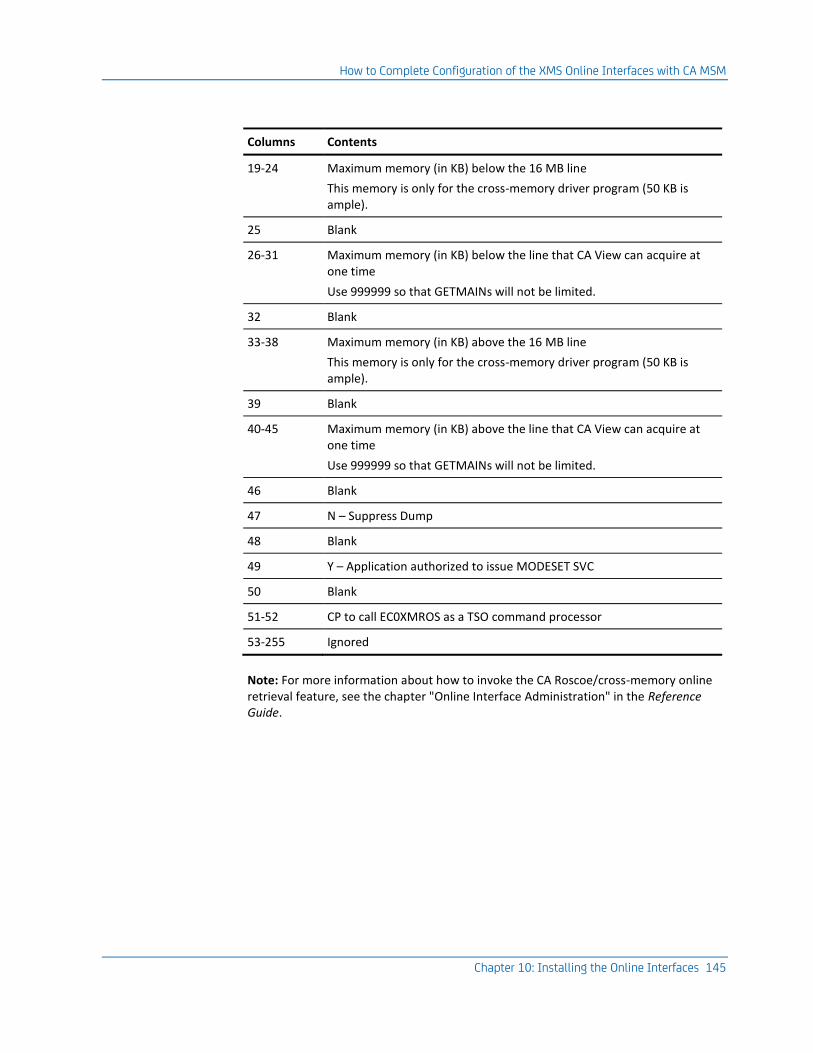
How to Complete Configuration of the XMS Online Interfaces with CA MSM
Chapter 10: Installing the Online Interfaces 145
Columns Contents
19-24 Maximum memory (in KB) below the 16 MB line
This memory is only for the cross-memory driver program (50 KB is ample).
25 Blank
26-31 Maximum memory (in KB) below the line that CA View can acquire at one time
Use 999999 so that GETMAINs will not be limited.
32 Blank
33-38 Maximum memory (in KB) above the 16 MB line
This memory is only for the cross-memory driver program (50 KB is ample).
39 Blank
40-45 Maximum memory (in KB) above the line that CA View can acquire at one time
Use 999999 so that GETMAINs will not be limited.
46 Blank
47 N – Suppress Dump
48 Blank
49 Y – Application authorized to issue MODESET SVC
50 Blank
51-52 CP to call EC0XMROS as a TSO command processor
53-255 Ignored
Note: For more information about how to invoke the CA Roscoe/cross-memory online retrieval feature, see the chapter "Online Interface Administration" in the Reference Guide.

How to Complete Configuration of the XMS Online Interfaces with CA MSM
146 Installation Guide
CA Roscoe Cross-Memory Notes
Be aware of the following:
■ Start the primary SARXMS region with the XMSSUB=YES parameter.
The XMSSUB=YES parameter must only be used in an XMS address space with a default subsystem ID (SUBSYS=XMC0 or not specified).
■ If multiple SARXMS regions are started, they must be started with XMSSUB=NO parameter.
Only the primary XMS region can have XMSSUB=YES specified.
■ The XMS regions must have the XMS=YES parameter to make it accessible.
■ The EBCXMCTR table must be assembled during installation to define the relationship between CA View and CA Deliver database high-level qualifiers.
The table contains an EBCXMOPT macro to define initialization options and the EBCXMTRN macro for each CA View database transaction.
The EBCXMTRN macro also contains options for the specific database as follows:
■ SUBSYS= parameter of the cross-memory task must match the SUBSYS= parameter specified in the EBCXMCTR table entry.
■ RECON=YES can be used to allow reconnection (after a TSO terminal error) at the point of exit.
■ TIMEOUT= specifies how long TSO is to wait for the XMS session to respond after the user enters input, in seconds.
We recommend as high a value as possible but not less than 240 (4 minutes).
Note: The SUBMAX= parameter controls the number of user connections, not the USERMAX= parameter. USERMAX= only applies when you are using the subtask with the CICS interface.
Install the CICS Pseudo-Conversational Option
Important! This option uses the cross-memory feature distributed with CA View and must be installed with that feature.
Note: For more information about cross-memory, see Install Cross Memory Services.

How to Complete Configuration of the XMS Online Interfaces with CA MSM
Chapter 10: Installing the Online Interfaces 147
Installation Steps
The following steps are required to install the CICS Pseudo Conversational Option. Each step is explained in detail in the sections that follow.
1. Place the CA View load libraries into DFHRPL and STEPLIB.
2. Code the PCT and PPT Table Entries to CICS.
3. (Optional) Prepare the interface to a user-written CICS menu system.
Step 1: Add Modules to DFHRPL and STEPLIB
The CA View load library is required in the CICS DFHRPL and in the STEPLIB in the CICS region.
Note: If the CAI.CVDELOAD load library is in the linklist, it does not have to be included as a STEPLIB in the CICS region.
Be sure the following modules are available in the DFHRPL concatenation of libraries:
■ EC0CICUX
■ EC0CIEND
■ EC0CINIT
■ EC0CISRV
■ EC0XMCIC
■ EC0Crelease-number
Where:
release-number represents the CICS release number.
– CTS 3.1 release number: 0640
– CTS 3.2 release number: 0650
– CTS 4.1 release number: 0660
– CTS 4.2 release number: 0670
– CTS 5.1 release number: 0680
You can copy the six modules to the DD statement DFHRPL in your CICS task. However, we strongly recommend that you concatenate CAI.CVDELOAD to the DD statement DFHRPL.
Note: Several CA View modules are loaded (MVS load) from the CICS STEPLIB or LINKLIST. Verify that the entire CA View load library is defined in the CICS STEPLIB or is included in the linklist.

How to Complete Configuration of the XMS Online Interfaces with CA MSM
148 Installation Guide
Step 2: Code the PCT and PPT Table Entries to CICS
The CICS transactions and programs were previously defined in the MSM configuration step. Review the following points to determine if they are applicable to your installation.
CICS Resource Definition Online Storage Protection
If you have CICS storage protection activated, the following resource definition online settings are required:
■ For all transactions
TASKDATALOC=ANY
TASKDATAKEY=CICS
■ For all programs
DATALOCATION=ANY
EXECKEY=CICS
PLT Start-up List
Add these table entries to the last phase of the PLT startup list to initialize the subtask that is used for cross-memory access:
DFHPLT TYPE=ENTRY,PROGRAM=DFHDELIM
DFHPLT TYPE=ENTRY,PROGRAM=EC0CINIT
PLT Shutdown List
Add this table entry to the first phase of the PLT shutdown list to be sure that the subtask that executes as part of the online facility shuts down correctly when CICS shuts down:
DFHPLT TYPE=ENTRY,PROGRAM=EC0CIEND
DFHPLT TYPE=ENTRY,PROGRAM=DFHDELIM

How to Complete Configuration of the XMS Online Interfaces with CA MSM
Chapter 10: Installing the Online Interfaces 149
Optional DCT Entries
Specify a value for the DESTID parameter in the EBCXMOPT macro in the EC0XMCTR module and corresponding DCT entries. This value defines a transient data destination for messages issued by the subtask.
Note: Specify a blank for DESTID to suppress the generation of informational messages from the subtask.
The DCT entries for a DESTID of XMC0 are:
SARLOG DFHDCT TYPE=SDSCI, FOR CICS MESSAGES AND SHUTDOWN
BLKSIZE=250, STATISTICS
BUFNO=1,
DSCNAME=SARLOG,
RECFORM=VARUNBM,
RECSIZE=242,
TYPEFLE=OUTPUT
XMC0G DFHDCT TYPE=EXTRA,
DESTID=XMC0,
DSCNAME=SARLOG

How to Complete Configuration of the XMS Online Interfaces with CA MSM
150 Installation Guide
Step 3: (Optional) Invoke the Product from a CICS Menu System
If you want to invoke CA View from a user-written CICS menu system, and then return to that menu system when you exit from CA View, do the following:
Invoke CA View from the menu system using the following CICS command:
EXEC CICS START TRANSID(VIEW transaction-id)
TERMID(EIBTRMID)
FROM(data-area)
LENGTH(4)
where:
TRANSID(VIEW transaction-id)
Specifies the CA View transaction ID.
TERMID(EIBTRMID)
Specifies the terminal that a CA View transaction will communicate with.
FROM(data-area)
Specifies the optional variable length character string.
The format of the data-area parameter is:
tran,mode,sysoutid,jobnum,code
where:
tran
Specifies the return menu CICS transaction to be started when CA View finishes
mode
Specifies the CA View user mode (ALL, SAR, SARO, EXP, EXPO) for this user
If mode is not specified, the last mode that the user was in is used.
sysoutid
Specifies the SYSOUT ID or generic ID (with *) to be selected
jobnum
Specifies the JES2 job number of the SYSOUT ID to be selected
code
Indicates the selection code to be used (S, Pn, Vn, Jn, and so on)
If code is not specified, the user is presented with the SYSOUT Selection List.
Note: None of the data-area parameters is required.
LENGTH (4)
Specifies the number of bytes in the data field being passed.

How to Complete Configuration of the XMS Online Interfaces with CA MSM
Chapter 10: Installing the Online Interfaces 151
When CA View receives control, it retrieves the four-byte return transaction ID and saves it from iteration to iteration.
If the retrieve fails, CA View retains the information that it was started directly from a terminal, not a menu system.
When CA View finishes processing, it determines whether it should return to a menu system by starting the return transaction.
If there is a saved transaction ID, the product starts the return transaction before it exits to CICS by issuing:
EXEC CICS START TRANSID(return transaction-id)
TERMID(EIBTRMID)
NOCHECK
CICS Notes
The cross-memory CICS access involves two different address spaces: the CICS address spaces and the XMS address spaces.
CICS Address Spaces
The user's CICS transactions and the cross memory support subtask reside in these address spaces.
■ If multiple CICS regions are used to access CA View, each CICS region will have an XMS support subtask
■ If you are using CICS/MRO, CA View normally runs in an AOR (application region).

How to Complete Configuration of the XMS Online Interfaces with CA MSM
152 Installation Guide
XMS Address Spaces
Be aware of the following:
■ The primary SARXMS region can be started with the XMSSUB=YES or XMSSUB=NO parameter.
■ CICS has a router subtask in its region and does not require the XMSSUB=YES function. However, we recommend that you start the primary XMS region with XMSSUB=YES.
■ If multiple SARXMS regions are started, they must be started with XMSSUB=NO parameter.
Only the primary XMS region can have XMSSUB=YES specified.
■ The XMS regions must have the XMS=YES parameter to make it accessible.
■ The SUBSYS= parameter must match the EC0XMCTR table entry for the CICS transaction.
■ The EBCXMCTR table must be assembled during installation to define the relationship between CA View and CA Deliver database high-level qualifiers.
The table contains an EBCXMOPT macro to define initialization options and the EBCXMTRN macro for each CICS user transaction.
The EBCXMTRN macro also contains options for the specific database as follows:
■ SUBSYS= parameter can be used to route the CA View transaction to an alternate XMS subsystem ID. The SUBSYS= of the cross-memory task must match the SUBSYS= parameter specified in the EBCXMCTR table entry.
■ TRANID=parameter specifies the CA View transaction identifier for CICS.
■ RECON=YES can be used to allow reconnection (after a CICS terminal error) at the point of exit.
Note: Do not specify RECON=YES if you use a multi-session manager that assigns LU names from a pool of names. Coding RECON=YES under these conditions could allow you to be connected to another user's session.
For more information, see Multi-Session Managers later in this chapter.
■ TIMEOUT= specifies how long CICS is to wait for the XMS session to respond after the user enters input, in seconds.
We recommend as high a value as possible but not less than 240 (4 minutes).

How to Complete Configuration of the XMS Online Interfaces with CA MSM
Chapter 10: Installing the Online Interfaces 153
CICS XMS Subtask Startup
Use one of these methods to start the XMS subtask automatically:
■ When the CICS region is started, use the DFHPLTPI definition to automatically start the XMS subtask.
■ Define a transaction for the EC0CINIT program to allow for manual startup.
■ Write a CICS program to transfer control (XCTL) to EC0CINIT when you want to start the XMS subtask.
Until the XMS subtask is started, expect the transactions referencing EC0XMCIC to terminate with an error message that indicates that the XMS subtask is not active
Note:
■ When the CICS region is terminated, the DFHPLTSD definition is to be used to terminate the XMS subtask.
You can manually terminate the XMS subtask through a user application program that links the EC0CIEND, or you can use the optional transaction defined for EC0CIEND for manual termination.
■ If you want to terminate the XMS subtask manually, we recommend that you use the DFHPLTSD entry to terminate the XMS subtask. This definition is needed to clean up linkages to the XMS address spaces.
■ To prevent users from shutting down the XMS subtask, secure the optional transaction for program EC0CIEND.

How to Complete Configuration of the XMS Online Interfaces with CA MSM
154 Installation Guide
Multi-Session Managers Using Virtual LU Names
Multi-session manager products, for example CA TPX Session Management (CA TPX), can be configured to assign an LU name to a user's terminal at the time the user selects the CICS application.
Important! This assignment means that a user can enter CICS each time with a different terminal ID which can cause problems for CA View application.
For example: If a user uses a multi-session manager to end a session, or shuts the PC down, CA View does not know that the user has left. Another user might select CICS, be assigned to the same LU name as the previous user, and enter CA View with the same terminal ID as the previous user. CA View believes that there are two active users on the same terminal.
To prevent this situation, you can add a small amount of code to the CICS Autoinstall Control Program.
Note: The default name of this program is DFHZATDX and its source is located in SDFHSAMP.
If you are not a CICS systems programmer, discuss this situation with the person in your company who is responsible for CICS support and maintenance.
The sample code that follows shows how to clear an active user from the CA View application at terminal deletion time. Insert this code in your Autoinstall Control Program.
The source that is shipped with CICS contains this line:
* ==> PUT DELETE CODE HERE
Insert the code after that line.
LOAD EP=EC0XSLOC,ERRET=RETURN
LR R6,R0 GET EBCXSLOC ADDRESS
ICM R8,B'1111',0(R6) ADDR OF MAIN CONTROL BLOCK
BZ RETURN GET OUT IF NONE
LA R7,4(,R8) LOOK LIKE FIRST USER BLOCK
XSU_LOOP DS OH
ICM R7,B'1111',8(R7) USER BLOCK ADDR
BZ RETURN GET OUT IF DONE
CLC DELETE_TERM_ID,104(R7) FOR THIS TERMINAL?
BNE XSU_LOOP NO
TM 120(R7),X'01' ACTIVE ENTRY?
BZ XSU_LOOP NO
OI 120(R7),X'02' SHOW SESSION DONE
B RETURN EXIT PROGRAM

How to Complete Configuration of the XMS Online Interfaces with CA MSM
Chapter 10: Installing the Online Interfaces 155
This code does the following:
1. Attempts to load program EC0XSLOC
■ If the load fails, this is not the region containing CA View and it exits.
■ If CA View is active in this region, the first word of EC0XSLOC contains the address of the main control block.
If this word is zero, CA View is not active and the program exits.
2. Scans the chain of CA View user control blocks to find the terminal to be deleted
■ If the program finds the terminal ID, it makes sure that the user block is in use and is active, then it clears the appropriate fields.
■ If the block does not represent an active user, the program continues to search the chain to the end.
■ If the program gets to the end of the chain without finding the terminal ID, the program exits.
If you implement this change to the terminal deletion section of the Autoinstall Control Program, you can prevent the problems caused by the methods that were used to leave the CA View application.
Install the IMS Online Retrieval Option
Use these steps to install the IMS online retrieval option.
Important! This facility uses the cross-memory feature distributed with CA View and must be installed with that feature.
Note: For more information about cross-memory, see the topic Installing Cross-Memory Services in this chapter.
Installation Steps
This list summarizes the steps required to install the IMS Online Retrieval Option. Detailed instructions are in the sections that follow.
1. Code the IMS TRANSACT, PSB, and APPLCTN macros.
2. Run the PSB, ACB, and SYSGEN procedures.
3. Load EC0IMSUX Modules
Move load modules to IMSVS.PGMLIB.
Important! All JCL and macros provided in this section are provided as general examples only and must be modified according for your site's systems and standards.

How to Complete Configuration of the XMS Online Interfaces with CA MSM
156 Installation Guide
Step 1: Code the Macros
Use the examples in this section as a guide as you code these macros, and implement them in your IMS system.
■ (IMS) TRANSACT macro
■ PSB macros
■ APPLCTN macro
TRANSACT Macro
One or more transactions must be defined for the IMS online retrieval program SARXMIMS. Normally, only one transaction identifier is defined, although you can define multiple transactions.
This TRANSACT macro identifies the SARXMIMS transaction to IMS:
TRANSACT NAME=EC0XMIMS,SPA=(18)
PSB Macros
This PSB must be generated for the EC0XMIMS transaction:
PCB TYPE=TP,ALTRESP=YES,MODIFY=YES
PSBGEN PSBNAME=EC0XMIMS,LANG=ASSEM,COMPAT=YES
APPLCTN Macro
This APPLCTN must be generated for the SARXMIMS transaction:
APPLCTN PSB=EC0XMIMS
Step 2: Run the PSB, ACB, and SYSGEN Procedures
Use the macros created in Step 1. Code the Macros as input for the following procedures:
PSBGEN
ACBGEN
IMS SYSGEN
Step 3: Load EC0IMSUX Modules
Move load modules EC0IMSUX to IMSVS.PGMLIB.
Note: EC0IMSUX is in CAI.CVDELOAD and must be copied to IMSVS.PGMLIB.
How to Complete Configuration of the XMS Online Interfaces with CA MSM
Chapter 10: Installing the Online Interfaces 157
IMS Notes (New Version)
Be aware of the following:
■ The new IMS/DC Transaction Program (EC0XMIMS) is a replacement for the older SARXMIMS program.
■ The EC0XMIMS does not need to be linkedited to the ASMTDLI interface program. The transaction is now conversational with a SPASIZE=18 (this can be adjusted).
■ If you use extended color, the SEGSIZE= may need to be increased, because extended color data streams can be a 50% increase over the monochrome data stream size.
To determine the SEGSIZE= value, take the terminal that uses the interface with the largest screen size, in bytes, and apply the following formula:
ROWS * COLS * 1.5 = SEGSIZE
For example, a 3278-5 with a 27 x 132 screen size would be (27 * 132 * 1.5) = 5346. If the SEGSIZE= is too small, the terminal user will get an RC= "A6" message indicating that a message insert failed.
IMS/DC Parameter Relationships
The cross-memory IMS/DC access involves up to three different address spaces as follows:
■ IMS/DC message processing region address spaces
The user's IMS/DC transaction resides here. If multiple IMS/DC users are processing concurrently (input being processed by the XMS system), a separate IMS/DC message region is used for each user.
IMS/DC can control the maximum number of IMS/DC transactions executing at one time.
■ The XMS support subtask
■ The subtask is started when the XMSSUB=YES input parameter is used when an XMS address space is started.
■ The subtask can be in a separate XMS address space or share the address space with XMS or VTAM sessions.
■ The XMSSUB=YES must only be used in an XMS address space with a default subsystem ID (SUBSYS=XMC0 or not specified).
■ If multiple XMS address spaces are started, only one can have the XMSSUB=YES specified.
Note: All IMS/DC, TSO/XMS, ISPF/XMS and CA Roscoe/XMS sessions share the same XMS subtask.
■ XMS address spaces
See the topic that follows.

How to Complete Configuration of the XMS Online Interfaces with CA MSM
158 Installation Guide
IMS/DC Cross-Memory Notes
Be aware of the following:
■ The primary SARXMS region is to be started with the XMSSUB=YES parameter.
This region can be in a separate XMS address space or share the address space with XMS or VTAM sessions.
■ The XMSSUB=YES parameter must only be used in an XMS address space with a default subsystem ID (SUBSYS=XMC0 or not specified).
■ If multiple SARXMS regions are started, they must be started with XMSSUB=NO parameter.
Only the primary XMS region can have XMSSUB=YES specified.
■ The XMS regions must have the XMS=YES parameter to make it accessible.
■ The EBCXMCTR table must be assembled during installation to define the relationship between CA View and CA Deliver database high-level qualifiers. The table contains an EBCXMOPT macro to define initialization options and the EBCXMTRN macro for each CA View database transaction.
The EBCXMTRN macro also contains options for the specific database as follows:
■ SUBSYS= parameter of the cross-memory task
The parameter must match the SUBSYS= parameter specified in the EBCXMCTR table entry.
■ RECON=YES can be used to allow reconnection (after an ISPF terminal error) at the point of exit..
■ TIMEOUT= specifies how long ISPF is to wait for the XMS session to respond after the user enters input, in seconds.
We recommend a value as high as possible but not less than 240 (4 minutes).
To abort the XMS session and return the user to ISPF or the TSO command prompt, press the ATTN key.
Note:
■ The SUBMAX= parameter controls the number of user connections, not the USERMAX= parameter. USERMAX= only applies when you are using the subtask with the CICS interface.
■ For more information about the IMS online interface, see the chapter "Online Interface Administration" in the Reference Guide.
To control screen size manually, use these operands. The SNA query command can also be used to determine the device characteristics.
Enter For Terminal Type

How to Complete Configuration of the XMS Online Interfaces with CA MSM
Chapter 10: Installing the Online Interfaces 159
Enter For Terminal Type
M2 3278-2 24 x 80 default screen size
M2H 3278-2 24 x 80 highlighting
M2X 3279-2 24 x 80 color highlighting
M2C 3279-2 24 x 80 color
M3 3278-3 32 x 80
M3H 3278-3 32 x 80 highlighting
M3X 3279-3 32 x 80 color highlighting
M3C 3279-3 32 x 80 color
M4 3278-4 43 x 80 highlighting
M4H 3278-4 43 x 80 highlighting
M4X 3279-4 43 x 80 color highlighting
M4C 3279-4 43 x 80 color
M5 3278-5 27 x 132
M5H 3278-5 27 x 132 highlighting
M5X 3279-5 27 x 132 color highlighting
M5C 3279-5 27 x 132 color
M6 3290 62 x 80
M6H 3290 62 x 80 highlighting
M7 3290 31 x 160
M7H 3290 31 x 160 highlighting
M8 3290 62 x 160
M8H 3290 62 x 160 highlighting
For other modifications to your system, see your VTAM programmer.

How to Configure the Online Interfaces Without CA MSM
160 Installation Guide
How to Configure the Online Interfaces Without CA MSM
The topics in this section describe the manual tasks you must perform if you are not using CA MSM to configure your product.
This section also describes the online interface options, the cross-memory drivers, and how to install the online interfaces, including these topics:
■ Online and cross-memory interfaces
■ Cross-memory drivers for ISPF, TSO, and CA Roscoe interfaces
■ Installation of these options:
– ISPF online retrieval option
– TSO online retrieval option
– CA Roscoe online retrieval option
– Cross-memory services
– ISPF/cross-memory online retrieval option
– TSO/cross-memory online retrieval option
– VTAM online retrieval option
– CA Roscoe/cross-memory online retrieval option
– CICS pseudo-conversational option
– IMS online retrieval option
Online Interfaces
The following table lists the online interfaces, whether cross-memory services (XMS) must be installed and any special advantages of using the interface.
Online Interface XMS Advantages
ISPF NO Provides full online access without the need for a cross-memory region
ISPF/XMS YES Does not require the STEPLIB to be APF-authorized
To simplify migration, you can run multiple releases of CA View concurrently.
TSO NO Provides full online access without the need for a cross-memory region

How to Configure the Online Interfaces Without CA MSM
Chapter 10: Installing the Online Interfaces 161
Online Interface XMS Advantages
TSO/XMS YES Does not require the STEPLIB to be APF-authorized
To simplify migration, you can run multiple releases of CA View concurrently.
VTAM YES Supports extended data stream to queriable terminals
CICS YES To simplify migration, you can run multiple releases of CA View concurrently.
IMS/DC YES
CA Roscoe NO Provides full online access without the need for a cross-memory region
CA Roscoe/XMS YES Does not require the STEPLIB to be APF-authorized
To simplify migration, you can run multiple releases of CA View concurrently.
Cross-Memory Services Interface (XMS)
The cross-memory services interface manages several interfaces; this allows you to control online access with a single operator interface. Advantages of the interfaces are discussed later in this chapter.
The parameters in the startup procedure for the cross-memory task allow you to control:
■ The maximum number of users allowed on the system
■ Whether to cancel users when they are inactive for a specified time (CANCEL and LONGWAIT)
Note: For information about startup parameters, see Installing Cross-Memory Services later in this chapter.
The operator commands available to modify the cross-memory task allow you to:
■ Cancel users
■ Suspend additional logons
■ List online usage statistics
■ Modify selected cross-memory startup JCL parameters
Note: For more information about online interface, see the chapter "Online Interface Administration" in the Reference Guide.

How to Configure the Online Interfaces Without CA MSM
162 Installation Guide
Cross-Memory Drivers for Interfaces
You can use cross-memory services drivers to run the TSO, ISPF, and CA Roscoe online interfaces.
The advantages of using these drivers are:
■ Users are authorized by cross-memory drivers.
When you use the cross-memory services drivers for the ISPF, TSO, or CA Roscoe interfaces, users are authorized by cross-memory and do not also need authorization from the online interface (for example, TSO).
■ Multiple versions of CA View can run simultaneously.
When you use the cross-memory services drivers for the ISPF, TSO, or CA Roscoe interfaces, you can run multiple versions of CA View concurrently. This ability supports migration; it makes it easier to migrate when you are converting to a new version level of CA View.
You can also run multiple versions of the online interfaces simultaneously.
Restrictions
These restrictions apply when you execute the program using the cross-memory drivers for TSO, ISPF, and CA Roscoe:
■ TSO SUBMIT is not used. The SUBMIT occurs from the connected cross memory region.
■ Direct reprints from the user have the JES banner pages of the cross memory region. The internal system banner page can be used to check the user requesting the reprint.
User Exits
User exits run in the cross-memory region and do not have access to TSO or CA Roscoe allocations.
Install the ISPF Online Retrieval Option
The ISPF online retrieval option runs under the IBM Interactive System Productivity Facility (ISPF) for z/OS Version 3.0 and higher.
Note: For more information about the ISPF Online Retrieval Option, see the chapter "Online Interface Administration" in the Reference Guide.
How to Configure the Online Interfaces Without CA MSM
Chapter 10: Installing the Online Interfaces 163
Installation Steps
This list summarizes the steps to install the ISPF online retrieval option. Detailed instructions are in the sections that follow.
1. (Optional) Add STEPLIB DD statements to the TSO LOGON procedures if the load modules are not in a linklist library.
2. (Not SPF) Add the panel and command table libraries to the TSO logon procedures.
3. (Optional) Add the mount attribute to the TSO user IDs.
4. (Optional) Modify an ISPF Selection Menu to Select Online Retrieval feature.
(Optional) Step 1: Add STEPLIB Statements
The action you take in this step depends on what you did during the base-product installation—specifically, did you:
■ Authorize the program load library
or
■ Copy the modules to a system authorized library
If the CA View load modules were not copied to one of the libraries in the linklist, proceed with this step; otherwise go to the next step.
Follow these steps:
1. Add STEPLIB DD statements to the TSO LOGON procedures if the load modules are not in a linklist library.
2. Add a STEPLIB DD statement for the library containing the product's load modules to the LOGON procedures for those TSO users who are going to be using the ISPF online retrieval option.
Note: If you have CA Deliver, the CA Deliver load modules must also be either in the linklist, or in a STEPLIB statement with this step.
Step 2: Add the Panel and Command Libraries (ISPF only)
If you are running under SPF, go to Step 3.
If your system runs CA View under ISPF, proceed with this step.
Follow these steps in your TSO logon procedure:
■ Concatenate the command table library CAI.CVDETBL0 to DD statement ISPTLIB.
■ Concatenate the panel library CAI.CVDEPNL0 to DD statement ISPPLIB.
Note: If you also plan to use SARSPF (the SPF interface), with multiple releases of CA View, concatenate CAI.CVDETBL0 first. Use the CAI.CVDETBL0 from the most current release.

How to Configure the Online Interfaces Without CA MSM
164 Installation Guide
Step 3: (Optional) Add the Mount Attribute to the TSO User IDs
If you want to add the mount attribute to your TSO user IDs, proceed with this step; otherwise, go to the next step.
Assign the mount attribute to all TSO users who are authorized to browse SYSOUT directly from an archival tape.
Use the TSO ACCOUNT command as follows to assign the mount attribute:
ACCOUNT
C (userid) MOUNT
END
Note: TSO users do not need the MOUNT attribute to access reports through the Expanded Access Tape Server (EAS), because the tape is mounted by the EAS started task and not the user's TSO session.
Step 4: (Optional) Modify an ISPF Selection Menu to Select Online Retrieval
If you want to add a selection code for the online retrieval feature to one of the ISPF selection menus, proceed with this step; otherwise, your detailed instructions for ISPF are complete.
To define your selection code, use this command:
PGM(SARSPF) PARM(high-level-database-name) NEWAPPL(SAR)
Use the value next to the NAME parameter on your Initialization Parameter Worksheet for PARM(high-level-database-name).
Note: Adding a selection code allows you to select the online retrieval feature in the same way you would select other ISPF options.
Panel Libraries
The names of the panel libraries vary from site to site and for the different releases of ISPF. These panel libraries are allocated to the ISPPLIB DD statement under TSO.
Be aware that some installations do not allow direct modifications of IBM panels and libraries. In this case, you can place the modified panels in user or site-specific libraries and concatenate them ahead of the IBM libraries.
Ask your system administrator for the specific ISPF panel library that applies to your site and contains the panel ISR@PRIM.
Note: The selection menus shown in the following examples are part of the program products SPF and ISPF, and are copyrighted by IBM.

How to Configure the Online Interfaces Without CA MSM
Chapter 10: Installing the Online Interfaces 165
Example 1
This example shows you how to add selection code R to the primary option menu ISR@PRIM for ISPF. Shaded lines identify the inserted lines.
%----------------------- ISPF/PDF PRIMARY OPTION MENU ------------------------
%OPTION ===>_ZCMD +
% +USERID - &ZUSER
% 0 +ISPF PARMS - Specify terminal and user parameters +TIME - &ZTIME
% 1 +BROWSE - Display source data or output listings +TERMINAL - &ZTERM
% 2 +EDIT - Create or change source data +PF KEYS - &ZKEYS
% 3 +UTILITIES - Perform utility functions
% 4 +FOREGROUND - Invoke language processors in foreground
% 5 +BATCH - Submit job for language processing
% 6 +COMMAND - Enter TSO Command, CLIST, or REXX exec
% 7 +DIALOG TEST - Perform dialog testing
% 8 +LM UTILITIES - Perform library administrator utility functions
% C +CHANGES - Display summary of changes for this release
% R +SARSPF - Retrieve SYSOUT
% T +TUTORIAL - Display information about ISPF/PDF
% X +EXIT - Terminate ISPF using log and list defaults
%
+Enter%END+command to terminate ISPF.
)INIT
.HELP = ISR00003
&ZPRIM = YES /* ALWAYS A PRIMARY OPTION MENU */
&ZHTOP = ISR00003 /* TUTORIAL TABLE OF CONTENTS */
&ZHINDEX = ISR91000 /* TUTORIAL INDEX - 1ST PAGE */
)PROC
&ZSEL = TRANS( TRUNC (&ZCMD,'.')
0,'PANEL(ISPOPTA)'
1,'PGM(ISRBRO) PARM(ISRBRO01)'
2,'PGM(ISREDIT) PARM(P,ISREDM01)'
3,'PANEL(ISRUTIL)'
4,'PANEL(ISRFPA)'
5,'PGM(ISRJB1) PARM(ISRJPA) NOCHECK'
6,'PGM(ISRPTC)'
7,'PGM(ISPYXDR) PARM(ISR) NOCHECK'
8,'PANEL(ISRLPRIM)'
C,'PGM(ISPTUTOR) PARM(ISR00005)'
R,'PGM(SARSPF) PARM(VIEW.SYSTEM1) NEWAPPL(SAR)'
T,'PGM(ISPTUTOR) PARM(ISR00000)'
' ',' '
X,'EXIT'
*,'?' )
&ZTRAIL = .TRAIL
)END
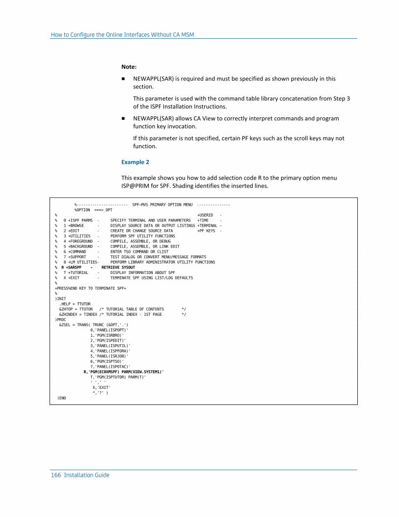
How to Configure the Online Interfaces Without CA MSM
166 Installation Guide
Note:
■ NEWAPPL(SAR) is required and must be specified as shown previously in this section.
This parameter is used with the command table library concatenation from Step 3 of the ISPF Installation Instructions.
■ NEWAPPL(SAR) allows CA View to correctly interpret commands and program function key invocation.
If this parameter is not specified, certain PF keys such as the scroll keys may not function.
Example 2
This example shows you how to add selection code R to the primary option menu ISP@PRIM for SPF. Shading identifies the inserted lines.
%----------------------- SPF–MVS PRIMARY OPTION MENU ---------------
%OPTION ===>_OPT
% +USERID -
% 0 +ISPF PARMS - SPECIFY TERMINAL AND USER PARAMETERS +TIME -
% 1 +BROWSE - DISPLAY SOURCE DATA OR OUTPUT LISTINGS +TERMINAL –
% 2 +EDIT - CREATE OR CHANGE SOURCE DATA +PF KEYS -
% 3 +UTILITIES - PERFORM SPF UTILITY FUNCTIONS
% 4 +FOREGROUND - COMPILE, ASSEMBLE, OR DEBUG
% 5 +BACKGROUND - COMPILE, ASSEMBLE, OR LINK EDIT
% 6 +COMMAND - ENTER TSO COMMAND OR CLIST
% 7 +SUPPORT - TEST DIALOG OR CONVERT MENU/MESSAGE FORMATS
% 8 +LM UTILITIES- PERFORM LIBRARY ADMINISTRATOR UTILITY FUNCTIONS
% R +SARSPF - RETRIEVE SYSOUT
% T +TUTORIAL - DISPLAY INFORMATION ABOUT SPF
% X +EXIT - TERMINATE SPF USING LIST/LOG DEFAULTS
%
+PRESS%END KEY TO TERMINATE SPF+
%
)INIT
.HELP = TTUTOR
&ZHTOP = TTUTOR /* TUTORIAL TABLE OF CONTENTS */
&ZHINDEX = TINDEX /* TUTORIAL INDEX - 1ST PAGE */
)PROC
&ZSEL = TRANS( TRUNC (&OPT,'.')
0,'PANEL(ISPOPT)'
1,'PGM(ISRBRO)'
2,'PGM(ISPEDIT)'
3,'PANEL(ISPUTIL)'
4,'PANEL(ISPFORA)'
5,'PANEL(ISRJOB)'
6,'PGM(ISPTSO)'
7,'PANEL(ISPOTAC)'
R,'PGM(EC0XMSPF) PARM(VIEW.SYSTEM1)'
T,'PGM(ISPTUTOR) PARM(T)'
' ',' '
X,'EXIT'
*,'?' )
)END

How to Configure the Online Interfaces Without CA MSM
Chapter 10: Installing the Online Interfaces 167
Example 3
This example shows you how to add selection code 3.R as a sub-option to the utilities menu ISRUTIL for SPF. Shaded lines identify the inserted lines.
%----------------------- Utility Selection Panel --------------------
%Option ===>_Z +
%1 +Library Compress or print data set. Print index listing. Print,
+ rename, delete, browse, edit or view members
%2 +Data Set Allocate, rename, delete, catalog, uncatalog, or display
+ information of an entire data set
%3 +Move/Copy Move, or copy members or data sets
%4 +Dslist Print or display (to process) list of data set names.
+ Print or display VTOC information
%5 +Reset Reset statistics for members of ISPF library
%6 +Hardcopy Initiate hardcopy output
%7 +Transfer Download ISPF Client/Server or Transfer data set
%8 +Outlist Display, delete, or print held job output
%9 +Commands Create/change an application command table
%11+Format Format definition for formatted data Edit/Browse
%12+SuperC Compare data sets (Standard Dialog)
%13+SuperCE Compare data sets Extended (Standard Dialog)
%14+Search-For Search data sets for strings of data (Standard Dialog)
%15+Search-ForE Search data sets for strings of data Extended (Extended Dialog)
%R +SARSPF Retrieve SYSOUT
)INIT
.ZVARS = '(ZCMD)'
.HELP = ISR30000
.ATTR (ZCMD) = 'PADC(USER)'
)PROC
&ZCMDWRK = TRUNC(&ZCMD,'.')
&ZTRAIL=.TRAIL
&ZSEL = TRANS (TRUNC (&ZCMD,'.')
1,'PGM(ISRUDA) PARM(ISRUDA1) SCRNAME(LIBUTIL)'
2,'PGM(ISRUDA) PARM(ISRUDA2) SCRNAME(DSUTIL)'
3,'PGM(ISRUMC) SCRNAME(MCOPY)'
4,'PGM(ISRUDL) PARM(ISRUDLP) SCRNAME(DSLIST)'
5,'PGM(ISRURS) SCRNAME(RESET)'
6,'PGM(ISRUHC) SCRNAME(HARDCOPY)'
7,'PANEL(ISPUDL) SCRNAME(DOWNLOAD)'
8,'PGM(ISRUOLP) SCRNAME(OUTLIST)'
9,'PANEL(ISPUCMA) ADDPOP SCRNAME(CMDTABLE)'
11,'PGM(ISRFMT) SCRNAME(FORMAT)'
12,'PGM(ISRSSM) SCRNAME(SUPERC)'
13,'PGM(ISRSEPRM) SCRNAME(SUPERCE) NOCHECK'
14,'PGM(ISRSFM) SCRNAME(SRCHFOR)'
15,'PGM(ISRSEPRM) PARM(S4) SCRNAME(SRCHFORE) NOCHECK'
R,'PGM(SARSPF) PARM(VIEW.SYSTEM1)'
' ',' '
*,'?' )
)END
Install the TSO Online Retrieval Option
This list summarizes the steps required to install the TSO online retrieval option. Each step is explained in detail in the sections that follow.
Note: For more information about the TSO Online Retrieval option, see the chapter "Online Interface Administration" in the Reference Guide.

How to Configure the Online Interfaces Without CA MSM
168 Installation Guide
1. (Optional) Add STEPLIB DD statements to the TSO LOGON procedures if the load modules are not in a linklist library.
2. (Optional) Add the mount attribute to the TSO user IDs.
(Optional) Step 1: Add STEPLIB DD Statements
The action you take in this step depends on what you did during the base-product installation—specifically, did you:
■ Authorize the program load library
or
■ Copy the modules to a system authorized library
If the load modules were not copied to one of the libraries in the linklist:
■ Add a STEPLIB DD statement (for the library containing the load modules) to the TSO LOGON procedures for those TSO users who are to use the native TSO online retrieval option.
If the load modules were copied to one of the libraries in the linklist, no STEPLIB DD statements are required.
Note: If you have CA View, the CA View load modules either must also be in the linklist, or placed in a STEPLIB statement with this step.
Step 2: (Optional) Add Mount Attributes
Assign the mount attribute to all TSO user IDs authorized to browse SYSOUT directly from an archival tape. Use the TSO ACCOUNT command to assign the mount attribute as follows:
ACCOUNT
C (userid) MOUNT
END
Note: TSO users do not need the MOUNT attribute to access reports through the Expanded Access Tape Server (EAS), because the tape is mounted by the EAS started task and not the user's TSO session.

How to Configure the Online Interfaces Without CA MSM
Chapter 10: Installing the Online Interfaces 169
Install the CA Roscoe Online Retrieval Option
The following steps are required to install the CA Roscoe/Cross-Memory Online Retrieval Option. Each step is explained in detail in the sections that follow.
1. (Optional) Concatenate the Load Module Library to the ETSOLIB DD statement, if the load modules were not copied to a linklist library.
2. Add the control statement for the RMOROS command processor to the Eligible Program List (EPL).
3. Invoke the SARROS command processor.
(Optional) Step 1: Concatenate the Load Module Library
If the load modules were not copied to a linklist library, concatenate the library that contains the load modules to the ETSOLIB DD statement in the CA Roscoe startup JCL.
Note: If you have CA Deliver, the CA Deliver load modules must also be either in the linklist or in an ETSOLIB statement with this step.
Step 2: Add SARROS Command Processor Statements
Add this Eligible Program List (EPL) control statement to member ETSOPGMS for the CA Roscoe user with the RO prefix.
Columns Contents
1–8 SARROS
9 Blank
10–12 Number of users allowed to access CA View at one time
13 Blank
14–17 CPU time slice
Use 9999 to prevent premature termination.
18 Blank
19–24 Maximum memory (in KB) below the 16 MB line
This value can vary depending on size of database and other factors (0001000 should be adequate).
25 Blank
26–31 Maximum memory (in KB) below the line that CA View can acquire at one time; use 999999 so that GETMAINs will not be limited
32 Blank

How to Configure the Online Interfaces Without CA MSM
170 Installation Guide
Columns Contents
33–38 Maximum memory (in KB) above the 16 MB line
This value can vary depending on features used (000512 should be adequate).
39 Blank
40–45 Maximum memory (in KB) above the line that CA View can acquire at one time
Use 999999 so that GETMAINs will not be limited.
46 Blank
47 N – Suppress dump
48 Blank
49 Y – Application authorized to issue MODESET SVC
50 Blank
51-52 CP to call SARROS as a TSO command processor
53-255 Ignore
Note: For more information about how to invoke the CA Roscoe online retrieval facility, see the chapter "Online Interface Administration" in the Reference Guide.
Install the Cross-Memory Services
The cross-memory services interface is required for the following online interfaces:
■ CICS pseudo-conversational
■ IMS
■ VTAM
■ ISPF/cross-memory
■ TSO/cross-memory
■ CA Roscoe/cross-memory
This list summarizes the steps to install the cross-memory services. Detailed instructions are in the sections that follow.
1. (Optional) Add the start procedure to PROCLIB for the cross-memory online task.
2. (Optional) Modify, assemble, and link edit the EC0XMCTR module.
3. Define security requirements.

How to Configure the Online Interfaces Without CA MSM
Chapter 10: Installing the Online Interfaces 171
Cross-Memory Services Regions
The VTAM and XMS (cross-memory services) interfaces operate in one or more cross-memory online regions.
A cross-memory region can be configured as:
■ An XMS only region
■ A VTAM only region
■ A combination of XMS and VTAM users
Be aware of the following:
■ Each cross-memory region is configured with the start-up parameters provided on the PARM= of the execute statement, and with an optional SYSIN DD statement.
The REGION= specification determines the maximum number of users supported.
■ Allow 20 MB (megabytes) for the XMS region plus 1 MB of storage for every two users.
For example, if you specified a REGION of 120 MB, you could specify:
USERMAX=200
If more users are needed, multiple regions can be started under the same SUBSYS= value and will be chained together.
Note: The REGION ID specified in the parameters must be different for each region, and if VTAM interface is used, a different SARAPPL= name will be needed for each region.
Interface Parameter Requirements
This table lists the optional and required parameters for each interface.
Note: The numbers next to the interface values refer to note references.
Parameter VTAM TSO TSO/ISPF CA Roscoe CICS IMS/DC
CANCEL Opt. (1) Opt. (1) Opt. (1) Opt. (1) Opt. (1) Opt. (1)
LGNFMT Opt. (2)
LGNSEC Opt. (3) Opt. (3) Opt. (3) Opt. (3) Opt. (3) Opt. (3)
LGNPROP Opt. (3) Opt. (3) Opt. (3) Opt. (3) Opt. (3) Opt. (3)
LONGWAIT Opt. (1) Opt. (1) Opt. (1) Opt. (1) Opt. (1) Opt. (1)
MSGLVL Opt. Opt. Opt. Opt. Opt. Opt.
SARAPPL Req.

How to Configure the Online Interfaces Without CA MSM
172 Installation Guide
Parameter VTAM TSO TSO/ISPF CA Roscoe CICS IMS/DC
SARVTDB Opt. (4)
SMFSESS Opt. (5) Opt. (5) Opt. (5) Opt. (5) Opt. (5) Opt. (5)
SUBSYS Opt. (6) Opt. (6) Opt. (6) Opt. (6) Opt. (6) Opt. (6)
USERMAX Req. Req. Req. Req. Req. Req.
VGRAPPL Opt. (7)
VTAMPASS Opt. (8)
VTMQUERY Opt. (9)
VTMSAA Opt. (9)
XMS Opt. (10) Opt. (11) Opt. (11) Opt. (11) Opt. (11) Opt. (11)
XMSSUB Req. (12) Req. (12) Req. (12) Req. (12)

How to Configure the Online Interfaces Without CA MSM
Chapter 10: Installing the Online Interfaces 173
Notes for Interface Parameter Requirements Table
1. The CANCEL= and LONGWAIT= values work together.
We recommend that you set CANCEL=YES and set LONGWAIT to a value appropriate for your site.
2. LGNFMT= should either not be specified, or should be specified as the default (LGNFMT=1), unless your session manager cannot provide logon data in the normal format.
If SARVTDB= is specified, LGNFMT=1 must be specified; any VTAM logon data will be ignored.
3. The LGNSEC= and LGNPROP= work together, and require the default SARUSxUX exit.
If LGNSEC=YES or LGNSEC=YESP is used (to indicate external security signon), the LGNPROP=YES/NO will be used to control whether security violations, database opens, and jobs submitted will use the user ID (LGNPROP=YES which is the default) or will use the XMS region's user ID.
It works this way:
– In the online region, the CA View database is opened before logon, and uses the XMS region's user ID.
– The CA Deliver database will be opened (read only) when the selection list processes entries that were archived through the CA Deliver system.
– Any SARBCH jobs submitted by the online will open both the CA View database (read/write) and the CA Deliver database under the authorization of the user who submitted the job.
– This authorization can be changed by doing one of the following:
Use the SARSUBUX exit to set a USERID=
Add a /*JOBFROM statement in the submitted JCL.
We recommend that you use the LGNPROP=YES to do normal user ID propagation.
4. The SARVTDB= only affects VTAM access, and is only to be used when the session manger cannot produce valid LOGON DATA.
For the valid formats supported by CA View, see the LGNFMT= parameter.
5. The SMFSESS= is to be specified when the user needs to collect user session statistics (CPU, logon/LOGOFF times, storage used, and so on).
6. The SUBSYS= is only to be specified when you are using a non-default subsystem ID under MVS.
The default is release specific; it does not require JCL/PARM changes when you are converting to a new software release.
7. Specify VGRAPPL= only to activate VTAM generic resource support.

How to Configure the Online Interfaces Without CA MSM
174 Installation Guide
Using generic resources allows an application to be known by a generic resource name. Users can then log on to a VTAM cross-memory region using the generic resource name.
The VGRAPPL= parameter must be specified with the SARAPPL= parameter. For more information, see the Reference Guide.
8. VTAMPASS= is only to be specified if you are going to be running a multi-region VTAM interface.
The other VTAM regions must specify the same parameters (LGNFMT= SARVDTB=, VTMQUERY=, VTMSAA=), or the interface might react in unpredictable ways.
9. VTMQUERY= is to be specified either as NORM (normal) or allowed to default to that value.
VTMQUERY=NONE works, but CA View cannot detect color/high-light terminal attributes so color/high-light support will be shut off.
VTAMSAA=NO is to be used if terminals cannot support the SNA QUERY LIST command, such as the older 3270/3290 devices and some older PC/3270 emulators.
10. XMS=NO is to be used when you are going to be using only the VTAM interface.
11. XMS=YES (the default) must be used to provide support for these interfaces.
12. XMSSUB=YES must be specified to provide support for these interfaces.
The XMSSUB=YES must reside in an XMS region with a default SUBSYS= value. If multiple XMS regions are started, only one region can have XMSSUB=YES. The other regions will still be available for user sessions, but their traffic will be routed through the region specifying XMSSUB=YES.
If you terminate the region with XMSSUB=YES, all sessions using the subtask are goint to fail (that is, all TSO/XMS, ISPF/XMS, CA Roscoe/XMS, IMS/DC regions). CICS has router SUBTASK in its region, and does not use the XMSSUB=YES function.
13. The OVERRIDE parameter is valid for all interfaces and is optional. It might be specified only in the execute statement PARM field and it cannot be coded in the SYSIN data set.
– If the parameter is not coded, the default duplicate parameter substitution hierarchy is SYSIN then the EXEC PARM.
– The OVERRIDE parameter determines whether parameters in the execute statement PARM field have precedence over parameters in the SYSIN data set.
– If OVERRIDE is coded in the execute statement PARM field, parameters specified in the execute statement PARM field will override duplicate specifications in the SYSIN data set.
– If OVERRIDE is not coded, parameters specified in the SYSIN data set are used and corresponding parameter specifications in the execute statement PARM field are ignored.

How to Configure the Online Interfaces Without CA MSM
Chapter 10: Installing the Online Interfaces 175
– The OVERRIDE parameter does not have any sub-parameters and it is coded as is in the execute statement PARM field.
– If this parameter is coded in the SYSIN data set, error message "EBCDRV99 OVERRIDE KEYWORD NOT ALLOWED IN SYSIN STATEMENTS - RUN ENDED U0016" is going to be displayed in the XMS job log and XMS will terminate with a return code of 16.
Step 1: Add the Start Procedure for the Cross-Memory Online Task
Add this start-procedure JCL for the cross-memory online retrieval task as member CBROSDRV to SYS1.PROCLIB. Sample JCL for this PROC is provided in member CBROSDRV of CAI.CVDEPROC.
//CBROSDRV EXEC PGM=EC0DRV,REGION=1024K,TIME=1440,
// PARM=('XMSSYS01,SARAPPL=SARVTAM,USERMAX=30,VTAMPASS=YES')
//*
//STEPLIB DD DSN=&CAI.CVDELOAD,DISP=SHR
//*
//SYSPRINT DD SYSOUT=A <--MESSAGE LOG (NEW, OUTPUT REQUIRED WHEN SUBMITTING
//* DUMP TO CA TECH SUPPORT)
//*
//SARLOG DD SYSOUT=A <--MESSAGE LOG (NEW, OUTPUT REQUIRED WHEN
//* SUBMITTING DUMP TO CA TECH
//* SUPPORT) ONLY USED WHEN XMSSUB=YES)
//*
//EBCUDUMP DD SYSOUT=A <--INTERNAL DUMP OUTPUT (NEW, OUTPUT REQUIRED WHEN
//* SUBMITTING DUMP TO CA TECH SUPPORT)
//*
//*
//SYSUDUMP DD SYSOUT=A <--MVS DUMP OUTPUT (OPTIONAL, MVS DUMP CAN BE ROUTED
//* WITH SYSMDUMP OR SYSABEND ALSO)
//* WARNING!!!! ABENDAID DUMPS ARE OF NO USE CORRECTING
//* PROBLEMS WITH SARXMS. YOU MUST ALWAYS SUPPRESS
//* ABENDAID IF YOU HAVE IT INSTALLED FOR THIS REGION.
//*
//SYSIN DD DSN=CAI.CVDEOPTN(PARMXMS),DISP=SHR

How to Configure the Online Interfaces Without CA MSM
176 Installation Guide
SYSIN Statements for Parameters
The REGIONID parameter is positional and must be specified in the PARM= statement of the cross-memory task JCL.
You can use SYSIN DD statements to specify the other cross-memory parameters.
If you are going to run multiple regions, specify these parameters in the PARM= statement:
SUBSYS=
SARAPPL=
XMS=
You can specify the rest of the parameters with SYSIN DD statements. If you place the SYSIN statements in a PDS member, you can alter the parameters without shutting down the cross-memory region. Be aware that the parameters do not take effect until the next time the region is shut down and restarted.
Note:
■ SYSIN parameters for cross memory services must start in column #1. Any parameter that does not begin in column #1 is treated as a comment and is ignored.
■ The OVERRIDE parameter cannot be coded in the SYSIN data set.
– If the OVERRIDE parameter is coded in the execute statement PARM field, a duplicate parameter in the PARM field and the SYSIN data set will be set to the value specified in the PARM field parameter.
– If the OVERRIDE parameter is not coded in the execute statement PARM field, a duplicate parameter in the PARM field and the SYSIN data set will be set to the value specified in the SYSIN.
More information:
Interface Parameter Requirements (see page 171)

How to Configure the Online Interfaces Without CA MSM
Chapter 10: Installing the Online Interfaces 177
Start Procedure Parameters
XMSSYS01 (in the PARM statement) specifies the one- to eight-character REGIONID. The REGIONID is positional—it must be the first value of the PARM= statement.
This value is used to define separate cross-memory regions attached to one MVS subsystem (specified by the SUBSYS parameter).
Note: Each separate SARXMS region has its own REGIONID. We suggest using the PROC name of the cross-memory-started task.
CANCEL=YES|NO
Indicates one of the following:
– CANCEL=YES specifies that a user who is inactive (no commands entered) for the time specified by the LONGWAIT parameter will be canceled, and the session will be terminated. With CANCEL=YES, all users are automatically canceled if the region is shut down by an operator command.
– CANCEL=NO specifies that the connection is not to be canceled, and the user status changes to LONGWAIT.
Default: NO
LGNFMT=n
Specifies the format of the data parameter when logging on to a VTAM region where n is a digit (1 through 3), as follows:
1 database//userid/password/newpass
2 userID/password/newpass/database/mode
3 database/mode
Default: 1.
LGNPROP=YES|NO
Indicates whether the CA View user ID is to be passed to MVS for propagation during submit processing.
This parameter is only valid if LGNSEC=YES is specified.
Default: YES.
LGNSEC=YES|NO|PASSWORD|YESP
Indicates whether there will be RACROUTE security checking.
LGNSEC must be YES or YESP if you are accessing a database that has the CA View initialization parameter SECURITY=EXTERNAL specified.
Modifications to default logon exit (SARUSXUX) is not required to implement external security. This exit is only provided so that you can customize the exit to provide any necessary functionality.

How to Configure the Online Interfaces Without CA MSM
178 Installation Guide
For example, to access external security packages directly, without SAF, you must modify and install the SARUSXUX user exit.
These values for LGNSEC are effective when the default exits are implemented:
Value
Result
YES
External security checking is performed using SAF calls.
External security verifies userid only for all cross-memory interfaces (with no interruption to the user).
A panel is presented to the user to verify userid and password.
Note: This panel is only presented when the user interface does not automatically send the userid to the XMS region.
Because the password is not forwarded, RACF or CA ACF2R Security (eTrust CA-ACF2) requires additional specifications. For RACF or CA ACF2, see Bypassing Password Verification in the chapter "Security" in the Reference Guide for implementation instructions.
NO
No SAF call to external security is performed.
The user ID is checked internally against CA View definitions.
If no match is found, CA View might or might not dynamically create a user ID depending on the value of your DEFMODE initialization parameter.
Review your DEFMODE values to be sure that they are appropriate.
PASSWORD
No call to external security is performed.
Internally, userid and password are verified.
YESP
External security checking is performed using SAF calls.
External security verifies userid and password for all cross-memory interfaces (with no interruption to the user).
A panel is presented to the user to verify the userid and password. This panel is only presented when the user interface does not automatically send the userid and password to the XMS region.
Default: NO.
LONGWAIT=nn
Specifies the number of minutes of inactivity (no commands entered) before a user's session is terminated.

How to Configure the Online Interfaces Without CA MSM
Chapter 10: Installing the Online Interfaces 179
The CANCEL parameter must be YES to terminate the session.
Default: 15.
MSGLVL=CRIT|ACTN|NORM|INFO|TRCE
Indicates the level of message to be written to the started task job log.
Unless they are suppressed, the CRITICAL and ACTION messages are written to the console. These settings cause the following types of messages to be written:
Setting Message
CRIT Only critical messages
ACTN Only critical and action messages
NORM Only critical, action, and normal messages
INFO All but trace messages
TRCE All messages
Default: NORM.
Note: This parameter does not suppress messages from the SYSPRINT log.
SARAPPL=applname
Specifies the SARVTAM APPLID which provides the VTAM user signon capability
Default: SARVTAM.
SARVTDB=high-level.databasename
Specifies that this database high-level qualifier must be used by all SARVTAM interface users
Typically, you would not specify this value and allow the user to specify which database to access when the user logs on. When this parameter is specified, any database specified at logon time with the VTAM logon command is ignored.
SMFSESS=nnn
Specifies whether SMF records are going to be collected for the cross-memory sessions.
The EBCSMFU1 macro documents the records available.
Default: zero—no record collection.
SUBSYS=name
Specifies the four-character MVS subsystem.
This value must match the value in the EC0XMCTR table.
Default: XMC0.
Note: The SUBSYS parameter does not apply to VTAM or IMS interface users.
USERMAX=nn

How to Configure the Online Interfaces Without CA MSM
180 Installation Guide
Specifies the maximum number of sessions to be allowed.
Default: 10.
VGRAPPL=name
Indicates the one- to eight-character generic resource name to be used to log on to VTAM cross memory regions.
VGRAPPL is only valid when specified with the SARAPPL parameter.
Default: None.
For more information, see the Reference Guide.
VTAMPASS=YES|NO
Indicates whether signon requests can be passed to other regions in this subsystem when this region cannot accept the request.
Possible reasons for not being able to accept a signon request are that the USERMAX parameter has been exceeded, or a SUSPEND operator command has been issued.
If VTAMPASS=YES is specified, include PASS in the AUTH value on the APPL statement in the VTAM definition. If you want to run multiple regions, VTAMPASS must be YES.
Default: NO.
VTMQUERY=ALL|NORM|NONE
Indicates whether the VTAM interface will QUERY terminals with dynamic log modes to determine the alternate screen size.
Use this parameter only to query VTAM terminals that support SNA QUERY commands, and do not have an alternate screen size defined in their log mode.
– For VTMQUERY=ALL, the interface will QUERY ALL terminals.
– For VTMQUERY=NORM, the interface will QUERY the terminal if the bind image indicates it is a VTAM QUERY terminal, and there is no alternate screen size defined.
– For VTMQUERY=NONE, the interface will not QUERY any terminals (and color will not be supported).
Default: NORM.
VTMSAA=YES|NO
Indicates whether all terminals are SAA compliant.
If you have the following:
– Older terminals that cannot support SAA (3290 terminals, for example
– These older terminals are going to be connecting with log modes that indicate that CA View should query their alternate screen size

How to Configure the Online Interfaces Without CA MSM
Chapter 10: Installing the Online Interfaces 181
You must specify VTAMSAA=NO or these terminals are not able to log onto the SARVTAM interface.
VTAMSAA=NO causes more overhead in logging on terminals than can be queried, and is only to be used when required.
XMS=YES|NO
Indicates whether cross-memory users are allowed to sign on to the region.
Set XMS=NO if this is a VTAM only region, and cross-memory is not to be supported.
Note: If XMS=NO, be sure that there is a VTAM ACB name coded in the SARAPPL= parameter.
Default: YES.
XMSSUB=YES|NO
XMSSUB=YES is required for ISPF cross-memory, TSO cross-memory, and CA Roscoe cross-memory sessions
All other interface users are to be set XMSSUB=NO.
Default: NO.
SARLOG DD Statement (Optional)
The optional SARLOG DD statement is used to specify where to write the log of user subtask messages.
This output is critical to resolving user subtask ABENDs, and is to be submitted to CA Technical Support along with the region or task dump created with an ABEND.
SYSPRINT DD Statement (Optional)
The optional SYSPRINT DD statement is used to specify where to write the log of cross-memory (SARXMS) messages.
This output is critical to resolving SARXMS ABENDs, and is to be submitted to CA Technical Support with the region or task dump created with an ABEND.

How to Configure the Online Interfaces Without CA MSM
182 Installation Guide
EBCUDUMP DD Statement
The EBCUDUMP DD statement is required, and is used to specify where to write a special dump of CA View control blocks that do not appear in normal MVS dump output.
This output is critical to resolving SARXMS abends and should be submitted to Technical Support with the region or task dump created with an ABEND.
Note:
■ On ABEND Output, only regular MVS dump output should be collected. Output from dump compression and analysis programs is not helpful to technical support—you might be required to recreate the dump.
■ Acceptable types include SYSUDUMP, SYSMDUMP, or SYSABEND output, in print-record format. IPCS/SVC dumps and CICS transaction or region dumps are also acceptable, but must be formatted for printing before they are placed on the tape.
■ The RMOXMS region uses the operator facility to abort a user's task for various problems. These problems might be a LONGWAIT time out, a VTAM I/O error, or a detected internal error, which appear in the log followed by a U0522 ABEND of the user subtask. No dump is generated.

How to Configure the Online Interfaces Without CA MSM
Chapter 10: Installing the Online Interfaces 183
STEPLIB for this Job
The action you take in this step depends on what you did during the base-product installation. Specifically, did you:
■ Authorize the program load library
or
■ Copy the modules to a system authorized library
Be aware of the following before you run this job:
■ If the CA View load modules were copied to an authorized library other than one of the linklist libraries, you must change the data set name on the STEPLIB DD statement.
■ If the load modules were copied to a linklist library, you must remove the STEPLIB DD statement.
■ If you have CA Deliver installed, you must consider these possibilities before you run the job listed previously above: If the CA View load modules were copied to an authorized library other than one of the linklist libraries, concatenate the CA Deliver load library as a second STEPLIB after the CA View load library in the STEPLIB DD statement.
■ If the load modules were copied to a linklist library, do nothing.
■ For the JES3 Environment
You must add the cross memory task to the JES3 task output table.
If you do not add this task, the P reprint select code cannot function properly.

How to Configure the Online Interfaces Without CA MSM
184 Installation Guide
Step 2: Modify, Assemble, and Link the EC0XMCTR Module
The EC0XMCTR module defines the relationship between a transaction identifier and the database, and session attributes. Also, the execution options for the cross-memory subtask system are also defined in this module. All interfaces except VTAM require the EC0XMCTR table.
Be aware of the following:
■ You must assemble the EC0XMCTR table during installation to define the relationship between CA View and CA Deliver database qualifiers, and the session options to be used, and to provide information used to build the XMS database table.
■ The table contains an EBCXMOPT macro to define initialization options and one EBCXMTRN, RMOXMTRN, or INBXMTRN macro for each TSO user session. For all users except VTAM, the transaction being used for each session must be defined in an EBCXMTRN statement. Only the database high-level qualifier is used for VTAM XMS users.
■ The transaction definition macros are searched by database name, and the first match is used. If no entry is found in the EC0XMCTR table, the session is rejected.
A sample EBCXMCTR source program is in the CAI.CVDESRC library, which is unloaded as part of CA Deliver's installation. The source is comprised of one or more assembler macros.
Format of the Macros
The first statement defines the system options and has this format:
EBCXMOPT DESTID=dest,SRVTRAN=transaction,MSGLVL=level, X
DESTID=CICS-dest,LOGWAIT=timout-val,SGNCNT=nn, X
USERMAX=user-number,WAITCNT=maxcount
The next group of statements is for each transaction and or database to be accessed; they have this format:
EBCXMTRN TYPE=SAR, X
TRANID=tranid,INDEX=high-level-name,TIMEOUT=sec, X
SUBSYS=subsysid,RECON=yes|no, X
MSGSUPP=yes|no
The last statement generates the transaction table:
EBCXMTRN TYPE=GEN
Finally, an assembler END statement is needed to end the macro:
END

How to Configure the Online Interfaces Without CA MSM
Chapter 10: Installing the Online Interfaces 185
EBCXMOPT Statement Parameters
The EBCXMOPT statement specifies these parameters.
DESTID=dest
Specifies the transient data destination to which messages from the CICS subtask are sent.
– Supply a DESTID to indicate that a queue (typically an extra partitioned queue that points to a SYSOUT data definition name) is defined.
– Leave DESTID blank to specify that messages from the CICS subtask are not to be captured.
XMC11=transaction
Specifies a four-character transaction that is to be added to the EBCXMC11 time out message.
This transaction allows for site specific tailoring of the time out message.
Default: None.
SRVTRAN=transaction
Specifies the transaction defined for EC0CISRV that is initiated as a service transaction when CA View CICS is initialized.
Default: XMC0.
MSGLVL=CRIT|ACTN|NORM|INFO|TRCE
Indicates the level of messages to display on the console.
These settings cause the following types of messages to be written:
CRIT
Displays only critical messages
ACTN
Displays only critical and action messages
NORM
Displays only critical, action, and normal messages
INFO
Displays all but trace messages
TRCE
Displays all messages
Default: NORM.
LOGWAIT=nnn

How to Configure the Online Interfaces Without CA MSM
186 Installation Guide
Indicates the amount of time a user is to wait to log on before the user's session times out.
Default: 200 (2 minutes, 00 seconds).
SUBMAX=nn
Indicates the total number of user control blocks that are allocated when a cross-memory subtask (other than CICS) is initialized.
Default: 500.
USERMAX=nn
Indicates the number of user control blocks that are allocated when CICS is initialized.
Default: 500.
SGNCNT=nn
Controls the number of logon control blocks allocated. These blocks are only used during the logon process. They are then reused and made available to other users attempting to log on.
When you increase the SGNCNT value, be aware that 256 bytes of ECSA are needed each time SGNCNT is increased by 1. Typically, 5 logon blocks are enough, but the value cannot exceed 50.
Default: 5.
WAITCNT=nnn
Indicates the number of sessions for which the subtask can wait.
Default: 256.
IMSMENU
Indicates the IMS/DC conversational menu to transfer to when CA View terminates.
If this value is not specified, the transaction in the SPA will be set to blanks.
IMSSPA
Indicates the size of the IMS/DC SPA.
The SPA size must be at least 18, but cannot exceed 100.
Default: 18.

How to Configure the Online Interfaces Without CA MSM
Chapter 10: Installing the Online Interfaces 187
EBCXMTRN Statement Parameters
The following parameters are specified in the EBCXMTRN statements:
TYPE=SAR|GEN
Specifies whether this is a transaction/database entry or the table is to be generated.
GEN
Generates the table
SAR
Contains a transaction code and index entry for CA View. EXPRESS and INB are valid for CA Deliver and CA Balancing Report Control (CA Balancing) if this is a combined table.
TRANID=tranid
Defines the transaction identifier for CICS.
For TSO, ISPF, and CA Roscoe (the cross-memory drivers), TRANID is ignored, and the first instance of the database high-level qualifier is used.
INDEX=high-level-name
Defines the high-level name of the CA View database.
TIMEOUT=nnn
Defines the time-out value, in seconds, to be used by this transaction.
– This value is used as the maximum wait time for a response from the SARXMS started task.
– This value must be greater than zero and less than 9999 seconds (which is two hours, 40 minutes).
– If you do not want any timeout to occur, you may specify TIMEOUT=NO.
Default: 240 seconds (four minutes).
SUBSYS=subsys-id
Defines a four-character MVS subsystem name, which must match the value specified for SUBSYS in the cross-memory started task JCL.
Each subsystem can support multiple databases and/or CICS/IMS regions.
Default: XMC0.
Note:
– There is no need to change the default unless you wish to bring up multiple cross-memory regions and separate transactions for testing or performance reasons.
– This subsystem name is not defined in SYS1.PARMLIB.

How to Configure the Online Interfaces Without CA MSM
188 Installation Guide
RECON=YES|NO
Indicates whether a user can reconnect to a lost session.
Default: NO.
MSGSUPP=YES|NO
Indicates whether a termination message is displayed when a session is terminated by a user.
Default: NO. This does not suppress messages generated from abnormal termination.
Note: The statements follow standard assembler coding conventions.
Macro Coding Example
Assume that two CA View systems have been created.
The databases for the two systems have high-level names of VIEW.SYSTEM1 and VIEW.SYSTEM2. A user must enter transaction identifier VW1 for the first system and VW2 for the second. The source for program EC0XMCTR contains the following control statements:
EBCXMOPT MSGLVL=CRIT,USERMAX=50
EBCXMTRN TRANID=VW1,INDEX=VIEW.SYSTEM1
EBCXMTRN TRANID=VW2,INDEX=VIEW.SYSTEM2
EBCXMTRN TYPE=GEN
END
EBCXMTRN TYPE=GEN must be the last statement before the END. This statement causes the EBCXMCTR CSECT to be generated.
Sample JCL
Sample JCL for this job is provided in member BROSXCTR of CAI.CVDEJCL. This job provides an SMP/E USERMOD that assembles and links an installation-dependent version of EC0XMCTR.

How to Configure the Online Interfaces Without CA MSM
Chapter 10: Installing the Online Interfaces 189
Parameters for Online Interfaces
The EC0XMCTR table defines the way linkages between the online drivers and the XMS region are established. Some of the parameters are used only in specific environments and others are used in all environments.
This table indicates which parameter affects each online interface.
All XMS interfaces require the EC0XMCTR table.
You must:
■ Assemble the table during installation to define the relationship between CA View and CA Deliver database high-level qualifiers and the session options that are to be used
■ Provide the information that is used to build the XMS database table.
Note: Be aware if both CA View and CA Deliver are installed and the CA View interface is doing any access to an associated DLVR database, the associated DLVR database needs to be added as an entry in the EC0XMCTR table.
The numbers in parentheses are explained in the notes section that follows the table.
Parameter TSO TSO/ISPF CA Roscoe CICS IMS/DC
DESTID Opt. (1)
XMC11 Opt. (8)
SRVTRAN Opt. (2)
MSGLVL Opt. Opt. Opt. Opt. Opt.
LOGWAIT Opt. Opt. Opt. Opt. Opt.
SUBMAX Opt. (3) Opt. (3) Opt. (3) Opt. (3)
USERMAX Opt. (4)
WAITCNT Opt. (5) Opt. (5) Opt. (5) Opt. (5) Opt. (5)
IMSMENU Opt. (6)
IMSSPA Opt. (7)
Note: The numbers next to the table values refer to note references.

How to Configure the Online Interfaces Without CA MSM
190 Installation Guide
Notes on Cross-Memory Service Parameters
1. DESTID= specifies the optional CICS destination where the message output is to be written.
2. SRVTRAN= specifies the service transaction ID.
This transaction is required for CICS, but you can use the default service transaction name XMC0.
3. SUBMAX= controls the maximum number of connections that the subtask program can manage.
The default is 500.
Each ISPF/XMS, TSO/XMS, CA Roscoe/XMS, or IMS/DC user connects through the XMS subtask, and the value defines the total number of users that can be connected from these interfaces at one time.
4. USERMAX= controls the maximum connections that can be managed by the subtask program.
The default is 500, which should be enough for most users. Each CICS region can manage this number of sessions. To increase the value, you must restart the CICS or XMS region that owns the subtask.
5. WAITCNT= specifies a value that should remain at the default value at this time.
Major performance problems occur if you set this to a lower value. Note that this value cannot be set above 255.
IMSMENU= specifies the IMS/DC conversational menu to transfer to when CA View ends.
6. If IMSMENU= is not specified, the SPA TRAN is set to blank upon termination.
7. IMSSPA= specifies the length of the IMS/DC spa to be used (IMS/DC only).
This parameter allows you to adjust the spa size so that CA View can transfer to user transactions.
IMS/DC requires that the spa size remain the same.
The spa size must be at least 18 bytes, and although you can specify a spa size of up to 100 bytes, only the first 18 bytes are used.
8. XMC11= specifies an optional 4-character CICS transaction ID that is displayed as part of message EBCXMC11 when a CICS user times out.

How to Configure the Online Interfaces Without CA MSM
Chapter 10: Installing the Online Interfaces 191
Step 3: Define Security Requirements for Security
You can define security requirements for CA Top Secret Security (eTrust CA Top Secret):
Follow these steps:
1. Rename the existing facility in the facility matrix table if you do not have a facility defined for RMOXMS:
user1=NAME=VIEWXMS
Be sure that the correct PGMname is defined for the new facility, where PGMname is either the first three characters or all the eight characters of the program name that is to make security calls (EC0 or EC0DRV).
2. Create region ACID for the facility:
TSS CRE(viewxms) pass(nopw,0) type(user) dept(dept)
mastfac(viewxms) NODSNCHK NORESCHK NOVOLCHK NOLCFCHK NOSUBCHK
3. Define the RMOXMS STC to the TSS STC record:
TSS ADDTO(STC) PROCNAME(viewxms) ACID(viewxms)
4. Give access to the ACIDs required to sign on to this facility:
TSS ADD(ACID) FAC(viewxms)
Install the ISPF/Cross-Memory Online Retrieval Option
The ISPF/Cross-Memory Online Retrieval Option runs under IBM's ISPF for z/OS Version 3.0 and higher.
Important! This interface requires Cross-memory services to be already installed. For more information, see Install Cross-Memory Services in this chapter.
Note: In the JCL for the cross-memory services task, the parameter XMSSUB must be set to YES.

How to Configure the Online Interfaces Without CA MSM
192 Installation Guide
Installation Steps
The following steps are required to install the ISPF/cross-memory online retrieval option. Each step is explained in detail later in the sections that follow.
1. (Optional) Add STEPLIB DD Statements to the TSO LOGON procedures if the load modules were not copied to a linklist library.
2. Add the panel and command table libraries to the TSO logon procedures. (For ISPF only, not for SPF.)
3. (Optional) Modify an SPF selection menu to select the online retrieval feature.
Note: For more information about the ISPF/cross memory online retrieval option, see the chapter "Online Interface Administration" in the Reference Guide.
(Optional) Step 1: Add STEPLIB DD Statements to the TSO LOGON Procedures
The action you take in this step depends on what you did during the base-product installation—specifically, did you:
■ Authorize the program load library
or
■ Copy the modules to a system authorized library
If the CA View load modules were not copied to one of the libraries in the linklist, proceed with this step; otherwise go to the next step.
For this interface, the libraries do not have to be APF authorized. Authorization is provided in the cross-memory installation. Multiple versions of this online interface can coexist in one TSO library concatenation.
Do one of the following:
■ Add a STEPLIB DD statement for the library that contains the load modules to the LOGON procedures for those TSO users who are going to use the ISPF/cross-memory online retrieval option.
■ Provide the load library that uses the ISPF LIBDEF facility.
Note: If multiple versions are going to be running simultaneously, or you also want to run a previous version of SARSPF or SARTSO, concatenate the load library you want SARSPF or SARTSO to use first.
More information:
Step 5. Modify the Skeleton JCL (see page 97)

How to Configure the Online Interfaces Without CA MSM
Chapter 10: Installing the Online Interfaces 193
Step 2: Add Panel and Command Table Libraries to TSO Logon
If you are going to run CA View under ISPF, proceed with this step. For Version 3 or higher, both the command table library and the panel library are used.
To add panel and command table libraries to the TSO LOGON procedure:
■ Concatenate the command table library CAI.CVDETBL0 to DD statement ISPTLIB.
■ Concatenate the panel library CAI.CVDEPNL0 to DD statement ISPPLIB.
Note: If you also plan to use SARSPF (the ISPF interface), and multiple versions of CA View, concatenate CAI.CVDETBL0 first. Use the CAI.CVDETBL0 from the most current release.
Step 3: (Optional) Modify an ISPF Selection Menu to Select Online Retrieval
If you want to add a selection code to one of the ISPF selection menus for the online retrieval feature, proceed with this step; otherwise, your ISPF detailed instructions are complete.
Note: If you add a selection code, you can select the online retrieval feature in the same way you select other ISPF options.
Use the value next to the NAME parameter on your Initialization Parameter Worksheet for PARM(high-level-database-name).
Use the values in this table for either SPF or ISPF.
Type Selection Code is Defined As
ISPF (all versions) 'PGM(EC0XMSPF) PARM(high-level-database-name) NEWAPPL(SAR)'
SPF 'PGM(EC0XMSPF) PARM(high-level-database-name)'
Panel Libraries
The names of the panel libraries vary from site to site and for the different releases of ISPF. These panel libraries are allocated to the ISPPLIB DD statement under TSO.

How to Configure the Online Interfaces Without CA MSM
194 Installation Guide
Be aware that some installations do not allow direct modifications of IBM panels and libraries. In this case, you can place the modified panels in user or site-specific libraries and concatenate them ahead of the IBM libraries.
Ask your system administrator for the specific ISPF panel library that applies to your site and contains the panel ISR@PRIM.
Note: The selection menus shown in the following examples are part of the program products SPF and ISPF, and are copyrighted by IBM.
Example 1
The following example shows you how to add selection code R to the primary option menu ISR@PRIM for ISPF. The bright, offset text identifies the inserted lines.
%----------------------- ISPF/PDF PRIMARY OPTION MENU --------------------
%OPTION ===>_ZCMD +
% +USERID - &ZUSER
% 0 +ISPF PARMS - Specify terminal and user parameters +TIME - &ZTIME
% 1 +BROWSE - Display source data or output listings +TERMINAL - &ZTERM
% 2 +EDIT - Create or change source data +PF KEYS - &ZKEYS
% 3 +UTILITIES - Perform utility functions
% 4 +FOREGROUND - Invoke language processors in foreground
% 5 +BATCH - Submit job for language processing
% 6 +COMMAND - Enter TSO Command, CLIST, or REXX exec
% 7 +DIALOG TEST - Perform dialog testing
% 8 +LM UTILITIES- Perform library administrator utility functions
% C +CHANGES - Display summary of changes for this release
% R +SARSPF - Retrieve SYSOUT
% T +TUTORIAL - Display information about ISPF/PDF
% X +EXIT - Terminate ISPF using log and list defaults
%
+Enter%END+command to terminate ISPF.
)INIT
.HELP = ISR00003
&ZPRIM = YES /* ALWAYS A PRIMARY OPTION MENU */
&ZHTOP = ISR00003 /* TUTORIAL TABLE OF CONTENTS */
&ZHINDEX = ISR91000 /* TUTORIAL INDEX - 1ST PAGE */
)PROC
&ZSEL = TRANS( TRUNC (&ZCMD,'.')
0,'PANEL(ISPOPTA)'
1,'PGM(ISRBRO) PARM(ISRBRO01)'
2,'PGM(ISREDIT) PARM(P,ISREDM01)'
3,'PANEL(ISRUTIL)'
4,'PANEL(ISRFPA)'
5,'PGM(ISRJB1) PARM(ISRJPA) NOCHECK'
6,'PGM(ISRPTC)'
7,'PGM(ISPYXDR) PARM(ISR) NOCHECK'
8,'PANEL(ISRLPRIM)'
C,'PGM(ISPTUTOR) PARM(ISR00005)'
R,'PGM(EC0XMSPF) PARM(VIEW.SYSTEM1) NEWAPPL(SAR)'
T,'PGM(ISPTUTOR) PARM(ISR00000)'
' ',' '
X,'EXIT'
*,'?' )
&ZTRAIL = .TRAIL
)END

How to Configure the Online Interfaces Without CA MSM
Chapter 10: Installing the Online Interfaces 195
Note:
■ NEWAPPL(SAR) is required and must be specified as shown previously in this section.
This parameter is used with the command table library concatenation from Step 3 of the ISPF Installation Instructions.
■ NEWAPPL(SAR) allows CA View to correctly interpret commands and program function key invocation.
If this parameter is not specified, certain PF keys such as the scroll keys may not function.
Example 2
The following example shows you how to add selection code R to the primary option menu ISP@PRIM for SPF. Shading identifies the inserted lines.
%----------------------- SPF–MVS PRIMARY OPTION MENU ---------------
%OPTION ===>_OPT
% +USERID -
% 0 +ISPF PARMS - SPECIFY TERMINAL AND USER PARAMETERS +TIME -
% 1 +BROWSE - DISPLAY SOURCE DATA OR OUTPUT LISTINGS +TERMINAL –
% 2 +EDIT - CREATE OR CHANGE SOURCE DATA +PF KEYS -
% 3 +UTILITIES - PERFORM SPF UTILITY FUNCTIONS
% 4 +FOREGROUND - COMPILE, ASSEMBLE, OR DEBUG
% 5 +BACKGROUND - COMPILE, ASSEMBLE, OR LINK EDIT
% 6 +COMMAND - ENTER TSO COMMAND OR CLIST
% 7 +SUPPORT - TEST DIALOG OR CONVERT MENU/MESSAGE FORMATS
% 8 +LM UTILITIES- PERFORM LIBRARY ADMINISTRATOR UTILITY FUNCTIONS
% R +SARSPF - RETRIEVE SYSOUT
% T +TUTORIAL - DISPLAY INFORMATION ABOUT SPF
% X +EXIT - TERMINATE SPF USING LIST/LOG DEFAULTS
%
+PRESS%END KEY TO TERMINATE SPF+
%
)INIT
.HELP = TTUTOR
&ZHTOP = TTUTOR /* TUTORIAL TABLE OF CONTENTS */
&ZHINDEX = TINDEX /* TUTORIAL INDEX - 1ST PAGE */
)PROC
&ZSEL = TRANS( TRUNC (&OPT,'.')
0,'PANEL(ISPOPT)'
1,'PGM(ISRBRO)'
2,'PGM(ISPEDIT)'
3,'PANEL(ISPUTIL)'
4,'PANEL(ISPFORA)'
5,'PANEL(ISRJOB)'
6,'PGM(ISPTSO)'
7,'PANEL(ISPOTAC)'
R,'PGM(EC0XMSPF) PARM(VIEW.SYSTEM1)'
T,'PGM(ISPTUTOR) PARM(T)'
' ',' '
X,'EXIT'
*,'?' )
)END

How to Configure the Online Interfaces Without CA MSM
196 Installation Guide
Example 3
This example shows you how to add selection code 3.R as a sub-option to the utilities menu ISPUTIL for ISPF. Shading identifies the inserted lines.
%----------------------- UTILITY SELECTION MENU --------------------
%OPTION ===>_OPT +
% +
% 1 +LIBRARY LIBRARY UTILITY:
+ PRINT INDEX LISTING OR ENTIRE DATASET
+ PRINT, RENAME, DELETE, OR BROWSE MEMBERS
+ COMPRESS DATASET
% 2 +DATASET DATASET UTILITY:
+ DISPLAY DATASET INFORMATION
+ ALLOCATE, RENAME, OR DELETE ENTIRE DATASET
+ CATALOG OR UNCATALOG DATASET
% 3 +MOVE/COPY MOVE OR COPY MEMBERS OR DATASETS
% 4 +CATALOG CATALOG MANAGEMENT:
+ DISPLAY OR PRINT CATALOG ENTRIES
+ INITIALIZE OR DELETE USER CATALOG ALIAS
% 5 +RESET RESET STATISTICS FOR MEMBERS OF SPF LIBRARY
% 6 +HARDCOPY INITIATE HARDCOPY OUTPUT
% 7 +VTOC DISPLAY OR PRINT VTOC ENTRIES FOR A DASD VOLUME
% 8 +OUTLIST DISPLAY, DELETE, OR PRINT HELD JOB OUTPUT
% 9 +SCRIPT/VS FORMAT,DISPLAY, AND OPTIONALLY PRINT SCRIPT TEXT
% R +SARSPF RETRIEVE SYSOUT
)INIT
.HELP = TU
)PROC
&SEL = TRANS( TRUNC (&OPT,'.')
1,'PGM(ISPUDA) PARM(UDA1)'
2,'PGM(ISPUDA) PARM(UDA1)'
3,'PGM(ISPUMC)'
4,'PGM(ISPUCA)'
5,'PGM(ISPURS)'
6,'PGM(ISPUHC)'
7,'PGM(ISPUVT)'
8,'PGM(ISPUOL) PARM(UOL01)'
9,'PGM(ISPUSC) PARM(SCRPTA)'
R,'PGM(EC0XMSPF) PARM(VIEW.SYSTEM1)'
' ',' '
*,'?' )
)END

How to Configure the Online Interfaces Without CA MSM
Chapter 10: Installing the Online Interfaces 197
ISPF Cross-Memory Notes
Be aware of the following:
■ The primary SARXMS region must be started with the XMSSUB=YES parameter.
■ The XMSSUB=YES parameter must only be used in an XMS address space with a default subsystem ID (SUBSYS=XMC0 or not specified).
■ If multiple SARXMS regions are started, they must be started with XMSSUB=NO parameter.
Only the primary XMS region can have XMSSUB=YES specified.
■ The XMS regions must have the XMS=YES parameter to make it accessible.
■ The EBCXMCTR table must be assembled during installation to define the relationship between CA View and CA Deliver database high-level qualifiers. The table contains an EBCXMOPT macro to define initialization options and the EBCXMTRN macro for each CA View database transaction.
The EBCXMTRN macro also contains options for the specific database as follows:
■ SUBSYS= parameter of the cross-memory task must match the SUBSYS= parameter specified in the EBCXMCTR table entry.
■ RECON=YES can be used to allow reconnection (after an ISPF terminal error) at the point of exit.
■ TIMEOUT= specifies how long ISPF waits for the XMS session to respond after the user enters input, in seconds.
We recommend as high a value as possible but not less than 240 (4 minutes).
To abort the XMS session and return the user to ISPF or the TSO command prompt, press the ATTN key.
Note: The SUBMAX= parameter controls the number of user connections, not the USERMAX= parameter. USERMAX= only applies when you are using the subtask with the CICS interface.
Install the TSO/Cross-Memory Online Retrieval Option
Important! This interface requires the cross-memory services to be installed. See the previous topic Install the Cross-Memory Services in this chapter.
Note: The parameter XMSSUB must be set to YES in the JCL for the cross-memory services task.
How to Configure the Online Interfaces Without CA MSM
198 Installation Guide
Installation Steps
The following steps are required to install the TSO/cross-memory online retrieval option. Each step is explained in detail in the sections that follow.
1. (Optional) Add STEPLIB DD Statements to the TSO LOGON procedures if the load modules were not copied to a linklist library.
2. (Optional) Create user CLISTs to execute the CA View TSO/XMS driver program.
(Optional) Step 1: Add STEPLIB DD Statements
The action you take in this step depends on what you did during the base-product installation—specifically, did you:
■ Authorize the program load library
or
■ Copy the modules to a system authorized library
If the CA View load modules were not copied to one of the libraries in the linklist, proceed with this step; otherwise go to the next step.
To add STEPLIB DD statements (for the library containing the CA View load modules) to the TSO LOGON procedures, do the following:
■ Add a STEPLIB DD statement for the library that contains the CA View load modules to the LOGON procedures for those TSO users who are to use the TSO/Cross-Memory Online Retrieval Option.
Note: For this interface, the libraries do not have to be APF-authorized—authorization is provided in the cross-memory installation. Multiple releases of this online interface can coexist in one TSO library concatenation.
For more information about executing the CA View TSOXMS driver program, see the chapter "Online Interface Administration" in the Reference Guide.
Step 2: (Optional) Set up the TSOXMS Driver Program
To create user CLISTs to execute the CA View TSOXMS driver program, issue the following command:
EC0XMTSO highlevel.databasename
Note: For more information about executing the CA View TSOXMS driver program, see the chapter "Online Interface Administration" in the Reference Guide.

How to Configure the Online Interfaces Without CA MSM
Chapter 10: Installing the Online Interfaces 199
TSO Cross-Memory Notes
Be aware of the following:
■ The primary SARXMS region should be started with the XMSSUB=YES parameter.
■ The XMSSUB=YES parameter must only be used in an XMS address space with a default subsystem ID (SUBSYS=XMC0 or not specified).
■ If multiple SARXMS regions are started, they must be started with XMSSUB=NO parameter.
Only the primary XMS region can have XMSSUB=YES specified.
■ The XMS regions must have the XMS=YES parameter to make it accessible.
■ The EBCXMCTR table must be assembled during installation to define the relationship between CA View and CA Deliver database high-level qualifiers.
The table contains an EBCXMOPT macro to define initialization options and the EBCXMTRN macro for each CA View database transaction.
The EBCXMTRN macro also contains options for the specific database as follows:
■ SUBSYS= parameter of the cross-memory task must match the SUBSYS= parameter specified in the EBCXMCTR table entry.
■ RECON=YES can be used to allow reconnection (after a TSO terminal error) at the point of exit.
■ TIMEOUT= specifies how long TSO is to wait for the XMS session to respond after the user enters input, in seconds.
We recommend as high a value as possible but not less than 240 (4 minutes).
To abort the XMS session and return the user to ISPF or the TSO command prompt, press the ATTN key.
Note: The SUBMAX= parameter controls the number of user connections, not the USERMAX= parameter. USERMAX= only applies when you are using the subtask with the CICS interface.
Install the VTAM Online Retrieval Option
Important! This facility uses the cross-memory feature distributed with CA View and must be installed with that feature.
Note: For more information about the cross-memory feature, see the Install Cross Memory Services section in this chapter.

How to Configure the Online Interfaces Without CA MSM
200 Installation Guide
Installation Steps
The following steps are required to install the VTAM online retrieval option. Each step is explained in detail in the sections that follow.
1. Define the APPL definition statement to VTAM.
2. (Optional) Create a USS definition table.
Step 1: Define the Application Program to VTAM
Add this application program definition to SYS1.VTAMLST:
* SYS1.VTAMLST(sarmajor)
sarmajor VBUILD TYPE=APPL
sarvtam APPL ACBNAME=sarvtam,AUTH=(PASS,ACQ),EAS=nn
where:
sarmajor
Specifies the application program major node name.
Use the SYS1.VTAMLST member name. The member name must be unique and must not be the same as the names on the APPL statement.
AUTH=(PASS,ACQ)
Is required when the cross-memory parameter VTAMPASS=YES is used to support multiple cross-memory regions.
If VTAMPASS=NO, you can specify AUTH=(ACQ). For more information about the VTAMPASS parameter, see the topic, Add the Start Procedure for the Cross-Memory Online Task, later in this chapter.
EAS=nn
Specifies the approximate number of concurrent sessions.
sarvtam
Specifies the application program minor node name.
■ This name must be unique within the network domain; it is the APPLID referenced in the USS definition table or LOGON command.
■ This name is also specified on the cross-memory SARAPPL parameter.
■ If not specified, the network-unique name (the name of the APPL definition statement) is used.

How to Configure the Online Interfaces Without CA MSM
Chapter 10: Installing the Online Interfaces 201
Step 2: (Optional) Create a USS Table Definition
To simplify the manner in which a user logs on to VTAM online retrieval, you can create a USS definition table for CA View.
Example
Assume that two CA View systems have been created. The databases for the two systems have high-level names of VIEW.SYSTEM1 and VIEW.SYSTEM2, and you want a user to simply enter one of the following to log on to VTAM online retrieval for the respective systems:
VIEW1
VIEW2
Create a USS definition table as follows:
USSTAB
*
* ENTRY FOR VIEW1
*
USSCMD CMD=VIEW1,REP=LOGON,FORMAT=PL1
USSPARM PARM=APPLID,DEFAULT=SARVTAM
USSPARM PARM=LOGMODE
USSPARM PARM=DATA,DEFAULT=VIEW.SYSTEM1
*
* ENTRY FOR VIEW2
*
USSCMD CMD=VIEW2,REP=LOGON,FORMAT=PL1
USSPARM PARM=APPLID,DEFAULT=SARVTAM
USSPARM PARM=LOGMODE
USSPARM PARM=DATA,DEFAULT=VIEW.SYSTEM2
USSEND

How to Configure the Online Interfaces Without CA MSM
202 Installation Guide
VTAM Cross-Memory Notes
Be aware of the following:
■ For VTAM only regions, you can start the primary SARXMS task with the XMSSUB=NO parameter. However if this is not a VTAM-only region, we recommend that you start the primary SARXMS region with the XMSSUB=YES parameter.
■ If multiple SARXMS regions are started, they must be started with XMSSUB=NO parameter.
Only the primary XMS region can have XMSSUB=YES specified.
■ VTAM only XMS regions can have the XMS=NO parameter to make it accessible.
■ All XMS interfaces require the EC0XMCTR table. You must assemble the table during installation to:
– Define the relationship between CA View and CA Deliver database high-level qualifiers and the session options to be used
– Provide information used to build the XMS database table. Only the database high-level qualifier is used for VTAM XMS users.
■ Specify the SARAPPL=applid parameter. This parameter provides VTAM user signon capability.
Note: When you are using multiple VTAM XMS regions, each region must have a unique applid.
■ To pass VTAM signon requests to other XMS regions, specify the VTAMPASS=YES parameter.
■ When you are using multiple VTAM XMS regions, the values for LGNFMT=, SARVDTB=, VTMQUERY=, and VTMSAA= must be the same in each region or the XMS interface may react in unpredictable ways.
■ To activate the VTAM generic resource support for your cross-memory regions, specify the VGRAPPL= parameter.
For more information about VTAM generic resources, see the following topic.
VTAM Generic Resource Name
If the VGRAPPL parameter is specified in an EMAS complex, this parameter specifies a common VTAM generic resource name for the entire EMAS complex.
Specifying the common VTAM generic resource name in the session request can initiate VTAM cross-memory sessions to any of the EMAS members.
When you are using the VTAM generic resource name, by default VTAM tries to request a session with an EMAS member in the same MVS image.
If it is not possible to get the session that was requested, VTAM uses normal load balancing when passing the session request to one of the active EMAS members.

How to Configure the Online Interfaces Without CA MSM
Chapter 10: Installing the Online Interfaces 203
Install the CA Roscoe/Cross-Memory Online Retrieval Option
The CA Roscoe/cross-memory online retrieval option runs as a command processor under ETSO/Roscoe.
Important! This interface requires cross-memory services to be installed. See the previous topic Installing Cross-Memory Services in this chapter. Be sure to set the parameter XMSSUB to YES in the JCL for the cross-memory services task.
Installation Steps
The following steps are required to install the CA Roscoe/Cross Memory Online Retrieval option. Each step is explained in detail in the sections that follow.
1. (Optional) Concatenate the Load Module Library to the ETSOLIB DD statement, if the load modules were not copied to a linklist library.
2. Add the control statement for the SARROS command processor to the Eligible Program List (EPL).
3. Invoke CA Roscoe/Cross Memory Online Retrieval.
(Optional) Step 1: Concatenate the Load Module Library
If the load modules were not copied to a linklist library, concatenate the library that contains the load modules to the ETSOLIB DD statement in the CA Roscoe start up JCL.
Note: If you have CA Deliver, the CA Deliver load modules must also be either in the linklist, or in a ETSOLIB statement with this step.
Step 2: Add SARROS Command Processor Statements
Important! This step is for CA Roscoe 6.0 and Higher.
Add this EPL control statement to member ETSOPGMS for the CA Roscoe user with the RO prefix.
Columns Contents
1-8 EC0XMROS
9 Blank
10-12 Number of users allowed to access CA View at one time
13 Blank
14-17 CPU time slice
Use 9999 to prevent premature termination.
18 Blank

How to Configure the Online Interfaces Without CA MSM
204 Installation Guide
Columns Contents
19-24 Maximum memory (in KB) below the 16 MB line
This memory is only for the cross-memory driver program (50 KB is ample).
25 Blank
26-31 Maximum memory (in KB) below the line that CA View can acquire at one time
Use 999999 so that GETMAINs will not be limited.
32 Blank
33-38 Maximum memory (in KB) above the 16 MB line
This memory is only for the cross-memory driver program (50 KB is ample).
39 Blank
40-45 Maximum memory (in KB) above the line that CA View can acquire at one time
Use 999999 so that GETMAINs will not be limited.
46 Blank
47 N – Suppress Dump
48 Blank
49 Y – Application authorized to issue MODESET SVC
50 Blank
51-52 CP to call EC0XMROS as a TSO command processor
53-255 Ignored
Note: For more information about how to invoke the CA Roscoe/cross-memory online retrieval feature, see the chapter "Online Interface Administration" in the Reference Guide.

How to Configure the Online Interfaces Without CA MSM
Chapter 10: Installing the Online Interfaces 205
CA Roscoe Cross-Memory Notes
Be aware of the following:
■ Start the primary SARXMS region with the XMSSUB=YES parameter.
The XMSSUB=YES parameter must only be used in an XMS address space with a default subsystem ID (SUBSYS=XMC0 or not specified).
■ If multiple SARXMS regions are started, they must be started with XMSSUB=NO parameter.
Only the primary XMS region can have XMSSUB=YES specified.
■ The XMS regions must have the XMS=YES parameter to make it accessible.
■ The EBCXMCTR table must be assembled during installation to define the relationship between CA View and CA Deliver database high-level qualifiers.
The table contains an EBCXMOPT macro to define initialization options and the EBCXMTRN macro for each CA View database transaction.
The EBCXMTRN macro also contains options for the specific database as follows:
■ SUBSYS= parameter of the cross-memory task must match the SUBSYS= parameter specified in the EBCXMCTR table entry.
■ RECON=YES can be used to allow reconnection (after a TSO terminal error) at the point of exit.
■ TIMEOUT= specifies how long TSO is to wait for the XMS session to respond after the user enters input, in seconds.
We recommend as high a value as possible but not less than 240 (4 minutes).
Note: The SUBMAX= parameter controls the number of user connections, not the USERMAX= parameter. USERMAX= only applies when you are using the subtask with the CICS interface.
Install the CICS Pseudo-Conversational Option
Important! This option uses the cross-memory feature distributed with CA View and must be installed with that feature.
Note: For more information about cross-memory, see Install Cross Memory Services.

How to Configure the Online Interfaces Without CA MSM
206 Installation Guide
Installation Steps
The following steps are required to install the CICS Pseudo Conversational Option. Each step is explained in detail in the sections that follow.
1. Place the CA View load libraries into DFHRPL and STEPLIB.
2. Code the PCT and PPT Table Entries to CICS.
3. (Optional) Prepare the interface to a user-written CICS menu system.
Step 1: Add Modules to DFHRPL and STEPLIB
The CA View load library is required in the CICS DFHRPL and in the STEPLIB in the CICS region.
Note: If the CAI.CVDELOAD load library is in the linklist, it does not have to be included as a STEPLIB in the CICS region.
Be sure the following modules are available in the DFHRPL concatenation of libraries:
■ EC0CICUX
■ EC0CIEND
■ EC0CINIT
■ EC0CISRV
■ EC0XMCIC
■ EC0Crelease-number
Where:
release-number represents the CICS release number.
– CTS 3.1 release number: 0640
– CTS 3.2 release number: 0650
– CTS 4.1 release number: 0660
– CTS 4.2 release number: 0670
– CTS 5.1 release number: 0680
You can copy the six modules to the DD statement DFHRPL in your CICS task. However, we strongly recommend that you concatenate CAI.CVDELOAD to the DD statement DFHRPL.
Note: Several CA View modules are loaded (MVS load) from the CICS STEPLIB or LINKLIST. Verify that the entire CA View load library is defined in the CICS STEPLIB or is included in the linklist.

How to Configure the Online Interfaces Without CA MSM
Chapter 10: Installing the Online Interfaces 207
Step 2: Define Transaction and Programs to CICS
To access CA View using CICS, define the required transactions and programs for the CICS interface.
Use the following sample jobs described to define:
■ Define sample CA View transaction: VW1
■ Define CA View service transaction: XMC0
■ Define optional CA View startup transaction: VWI
■ Define optional CA View shutdown transaction: VWX
■ Define CA View CICS retrieval programs:
– EC0CICUX
– EC0XMCIC
– EC0CINIT
– EC0CIEND
– EC0CISRV
– EC0C0620
– EC0C0621
– EC0C0622
– EC0C0630
– EC0C0640
– EC0C0650
– EC0C0660
– EC0C0670
– EC0C0680
■ Optionally, define one or more site specific transaction identifiers for the pseudo-conversational program EC0XMCIC.
Note:
■ You must define a separate, unique transaction identifier for each CA View database you want to access under CICS.
■ The sample job is located in CVDEJCL member CICSDEF.

How to Configure the Online Interfaces Without CA MSM
208 Installation Guide
Sample Job to Define CA View Transactions and Programs to CICS: //EXAMPLE JOB .....
//*********************************************************************
//* SAMPLE CICS JCL TO DEFINE PROGRAMS AND SAMPLE TRANSACTIONS *
//* FOR CA VIEW XMS INTERFACE *
//* *
//* NOTE: *
//* UPDATE PROCEDURE SUBSTITUTIONAL PARAMETERS FOR *
//* 'CICSLOAD' AND 'CICSCSD' ACCORDING TO SITE STANDARDS. *
//* *
//* MANUAL CHANGES ARE REQUIRED IN THIS JOB STREAM *
//* TO UPDATE SYSIN PORTIONS BEYOND THE CONTROL *
//* OF THE PROCEDURE'S SUBSTITUTIONAL PARAMETERS. *
//* *
//* EDIT GROUP(GGGGGG) WHERE GGGGGG IS THE CICS DEFINED GROUP *
//* FOR YOUR CA VIEW CICS DEFINITIONS. *
//* *
//*********************************************************************
//*
//CICSXMS PROC CICSLOAD='CICS.SDFHLOAD',
// CICSCSD='CICS.DFHCSD'
//*********************************************************************
//* DEFINE SAMPLE VIEW TRANSACTION: VW1 *
//* DEFINE SERVICE TRANSACTION: XMC0 *
//* DEFINE OPTIONAL STARTUP TRANSATION: VWI *
//* DEFINE OPTIONAL TERMINATE TRANSATION: VWX *
//* DEFINE CA VIEW CICS RETRIEVAL PROGRAMS: *
//* EC0CICUX *
//* EC0XMCIC *
//* EC0CINIT *
//* EC0CISRV *
//* EC0CIEND *
//* EC0C0620 *
//* EC0C0621 *
//* EC0C0622 *
//* EC0C0630 *
//* EC0C0640 *
//* EC0C0650 *
//* EC0C0660 *
//* EC0C0670 *
//* EC0C0680 *

How to Configure the Online Interfaces Without CA MSM
Chapter 10: Installing the Online Interfaces 209
//* *
//* ** OPTIONAL ** *
//* DEFINE YOUR SITE SPECIFIC VIEW TRANSACTION. USE THE DEFINE *
//* STATEMENTS FOR THE SAMPLE VW1 TRANSACTION AS YOUR MODEL. *
//* *
//* THE FOLLOWING PARAMETERS DEFINE VIEW TRANSACTION ID: VWC0 *
//* *
//* DEFINE TRANS(VWC0) GROUP(GGGGGG) PROG(EC0XMCIC) *
//* TASKDATAL(ANY) TASKDATAK(CICS) *
//* *
//* WHERE GGGGGG IS THE CICS DEFINED GROUP FOR YOUR *
//* CA VIEW CICS DEFINITIONS. *
//*********************************************************************
//STEP1 EXEC PGM=DFHCSDUP,REGION=1024K
//STEPLIB DD DSN=&CICSLOAD,DISP=SHR
//DFHCSD DD DSN=&CICSCSD,DISP=SHR
//SYSPRINT DD SYSOUT=*
//SYSIN DD DUMMY
//*
// PEND
//CICSXMS EXEC CICSXMS
//STEP1.SYSIN DD *
DEFINE TRANS(VW1) GROUP(GGGGGG) PROG(EC0XMCIC)
TASKDATAL(ANY) TASKDATAK(CICS)
DEFINE TRANS(XMC0) GROUP(GGGGGG) PROG(EC0CISRV)
TASKDATAL(ANY) TASKDATAK(CICS)
DEFINE TRANS(VWI) GROUP(GGGGGG) PROG(EC0CINIT)
TASKDATAL(ANY) TASKDATAK(CICS)
DEFINE TRANS(VWT) GROUP(GGGGGG) PROG(EC0CIEND)
TASKDATAL(ANY) TASKDATAK(CICS)
DEFINE PROG(EC0CICUX) GROUP(GGGGGG) LANGUAGE(ASSEMBLER)
DATALOCATION(ANY) EXECKEY(CICS)
DEFINE PROG(EC0XMCIC) GROUP(GGGGGG) LANGUAGE(ASSEMBLER)
DATALOCATION(ANY) EXECKEY(CICS)
DEFINE PROG(EC0CISRV) GROUP(GGGGGG) LANGUAGE(ASSEMBLER)
DATALOCATION(ANY) EXECKEY(CICS)
DEFINE PROG(EC0CINIT) GROUP(GGGGGG) LANGUAGE(ASSEMBLER)
DATALOCATION(ANY) EXECKEY(CICS)
DEFINE PROG(EC0CIEND) GROUP(GGGGGG) LANGUAGE(ASSEMBLER)
DATALOCATION(ANY) EXECKEY(CICS)

How to Configure the Online Interfaces Without CA MSM
210 Installation Guide
DEFINE PROG(EC0C0620) GROUP(GGGGGG) LANGUAGE(ASSEMBLER)
DATALOCATION(ANY) EXECKEY(CICS)
DEFINE PROG(EC0C0621) GROUP(GGGGGG) LANGUAGE(ASSEMBLER)
DATALOCATION(ANY) EXECKEY(CICS)
DEFINE PROG(EC0C0622) GROUP(GGGGGG) LANGUAGE(ASSEMBLER)
DATALOCATION(ANY) EXECKEY(CICS)
DEFINE PROG(EC0C0630) GROUP(GGGGGG) LANGUAGE(ASSEMBLER)
DATALOCATION(ANY) EXECKEY(CICS)
DEFINE PROG(EC0C0640) GROUP(GGGGGG) LANGUAGE(ASSEMBLER)
DATALOCATION(ANY) EXECKEY(CICS)
DEFINE PROG(EC0C0650) GROUP(GGGGGG) LANGUAGE(ASSEMBLER)
DATALOCATION(ANY) EXECKEY(CICS)
DEFINE PROG(EC0C0660) GROUP(GGGGGG) LANGUAGE(ASSEMBLER)
DATALOCATION(ANY) EXECKEY(CICS)
DEFINE PROG(EC0C0670) GROUP(GGGGGG) LANGUAGE(ASSEMBLER)
DATALOCATION(ANY) EXECKEY(CICS)
DEFINE PROG(EC0C0680) GROUP(GGGGGG) LANGUAGE(ASSEMBLER)
DATALOCATION(ANY) EXECKEY(CICS)
/*
CICS Resource Definition Online Storage Protection
If you have CICS storage protection activated, the following resource definition online settings are required:
■ For all transactions
TASKDATALOC=ANY
TASKDATAKEY=CICS
■ For all programs
DATALOCATION=ANY
EXECKEY=CICS
PLT Start-up List
Add these table entries to the last phase of the PLT startup list to initialize the subtask that is used for cross-memory access:
DFHPLT TYPE=ENTRY,PROGRAM=DFHDELIM
DFHPLT TYPE=ENTRY,PROGRAM=EC0CINIT
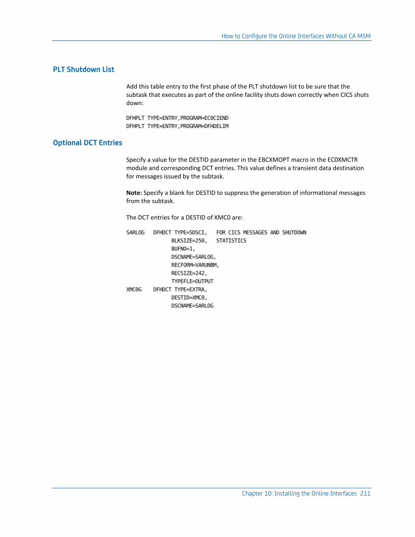
How to Configure the Online Interfaces Without CA MSM
Chapter 10: Installing the Online Interfaces 211
PLT Shutdown List
Add this table entry to the first phase of the PLT shutdown list to be sure that the subtask that executes as part of the online facility shuts down correctly when CICS shuts down:
DFHPLT TYPE=ENTRY,PROGRAM=EC0CIEND
DFHPLT TYPE=ENTRY,PROGRAM=DFHDELIM
Optional DCT Entries
Specify a value for the DESTID parameter in the EBCXMOPT macro in the EC0XMCTR module and corresponding DCT entries. This value defines a transient data destination for messages issued by the subtask.
Note: Specify a blank for DESTID to suppress the generation of informational messages from the subtask.
The DCT entries for a DESTID of XMC0 are:
SARLOG DFHDCT TYPE=SDSCI, FOR CICS MESSAGES AND SHUTDOWN
BLKSIZE=250, STATISTICS
BUFNO=1,
DSCNAME=SARLOG,
RECFORM=VARUNBM,
RECSIZE=242,
TYPEFLE=OUTPUT
XMC0G DFHDCT TYPE=EXTRA,
DESTID=XMC0,
DSCNAME=SARLOG

How to Configure the Online Interfaces Without CA MSM
212 Installation Guide
Step 3: (Optional) Invoke the Product from a CICS Menu System
If you want to invoke CA View from a user-written CICS menu system, and then return to that menu system when you exit from CA View, do the following:
Invoke CA View from the menu system using the following CICS command:
EXEC CICS START TRANSID(VIEW transaction-id)
TERMID(EIBTRMID)
FROM(data-area)
LENGTH(4)
where:
TRANSID(VIEW transaction-id)
Specifies the CA View transaction ID.
TERMID(EIBTRMID)
Specifies the terminal that a CA View transaction will communicate with.
FROM(data-area)
Specifies the optional variable length character string.
The format of the data-area parameter is:
tran,mode,sysoutid,jobnum,code
where:
tran
Specifies the return menu CICS transaction to be started when CA View finishes
mode
Specifies the CA View user mode (ALL, SAR, SARO, EXP, EXPO) for this user
If mode is not specified, the last mode that the user was in is used.
sysoutid
Specifies the SYSOUT ID or generic ID (with *) to be selected
jobnum
Specifies the JES2 job number of the SYSOUT ID to be selected
code
Indicates the selection code to be used (S, Pn, Vn, Jn, and so on)
If code is not specified, the user is presented with the SYSOUT Selection List.
Note: None of the data-area parameters is required.
LENGTH (4)
Specifies the number of bytes in the data field being passed.

How to Configure the Online Interfaces Without CA MSM
Chapter 10: Installing the Online Interfaces 213
When CA View receives control, it retrieves the four-byte return transaction ID and saves it from iteration to iteration.
If the retrieve fails, CA View retains the information that it was started directly from a terminal, not a menu system.
When CA View finishes processing, it determines whether it should return to a menu system by starting the return transaction.
If there is a saved transaction ID, the product starts the return transaction before it exits to CICS by issuing:
EXEC CICS START TRANSID(return transaction-id)
TERMID(EIBTRMID)
NOCHECK
CICS Notes
The cross-memory CICS access involves two different address spaces: the CICS address spaces and the XMS address spaces.
CICS Address Spaces
The user's CICS transactions and the cross memory support subtask reside in these address spaces.
■ If multiple CICS regions are used to access CA View, each CICS region will have an XMS support subtask
■ If you are using CICS/MRO, CA View normally runs in an AOR (application region).

How to Configure the Online Interfaces Without CA MSM
214 Installation Guide
XMS Address Spaces
Be aware of the following:
■ The primary SARXMS region can be started with the XMSSUB=YES or XMSSUB=NO parameter.
■ CICS has a router subtask in its region and does not require the XMSSUB=YES function. However, we recommend that you start the primary XMS region with XMSSUB=YES.
■ If multiple SARXMS regions are started, they must be started with XMSSUB=NO parameter.
Only the primary XMS region can have XMSSUB=YES specified.
■ The XMS regions must have the XMS=YES parameter to make it accessible.
■ The SUBSYS= parameter must match the EC0XMCTR table entry for the CICS transaction.
■ The EBCXMCTR table must be assembled during installation to define the relationship between CA View and CA Deliver database high-level qualifiers.
The table contains an EBCXMOPT macro to define initialization options and the EBCXMTRN macro for each CICS user transaction.
The EBCXMTRN macro also contains options for the specific database as follows:
■ SUBSYS= parameter can be used to route the CA View transaction to an alternate XMS subsystem ID. The SUBSYS= of the cross-memory task must match the SUBSYS= parameter specified in the EBCXMCTR table entry.
■ TRANID=parameter specifies the CA View transaction identifier for CICS.
■ RECON=YES can be used to allow reconnection (after a CICS terminal error) at the point of exit.
Note: Do not specify RECON=YES if you use a multi-session manager that assigns LU names from a pool of names. Coding RECON=YES under these conditions could allow you to be connected to another user's session.
For more information, see Multi-Session Managers later in this chapter.
■ TIMEOUT= specifies how long CICS is to wait for the XMS session to respond after the user enters input, in seconds.
We recommend as high a value as possible but not less than 240 (4 minutes).

How to Configure the Online Interfaces Without CA MSM
Chapter 10: Installing the Online Interfaces 215
CICS XMS Subtask Startup
Use one of these methods to start the XMS subtask automatically:
■ When the CICS region is started, use the DFHPLTPI definition to automatically start the XMS subtask.
■ Define a transaction for the EC0CINIT program to allow for manual startup.
■ Write a CICS program to transfer control (XCTL) to EC0CINIT when you want to start the XMS subtask.
Until the XMS subtask is started, expect the transactions referencing EC0XMCIC to terminate with an error message that indicates that the XMS subtask is not active
Note:
■ When the CICS region is terminated, the DFHPLTSD definition is to be used to terminate the XMS subtask.
You can manually terminate the XMS subtask through a user application program that links the EC0CIEND, or you can use the optional transaction defined for EC0CIEND for manual termination.
■ If you want to terminate the XMS subtask manually, we recommend that you use the DFHPLTSD entry to terminate the XMS subtask. This definition is needed to clean up linkages to the XMS address spaces.
■ To prevent users from shutting down the XMS subtask, secure the optional transaction for program EC0CIEND.

How to Configure the Online Interfaces Without CA MSM
216 Installation Guide
Multi-Session Managers Using Virtual LU Names
Multi-session manager products, for example CA TPX Session Management (CA TPX), can be configured to assign an LU name to a user's terminal at the time the user selects the CICS application.
Important! This assignment means that a user can enter CICS each time with a different terminal ID which can cause problems for CA View application.
For example: If a user uses a multi-session manager to end a session, or shuts the PC down, CA View does not know that the user has left. Another user might select CICS, be assigned to the same LU name as the previous user, and enter CA View with the same terminal ID as the previous user. CA View believes that there are two active users on the same terminal.
To prevent this situation, you can add a small amount of code to the CICS Autoinstall Control Program.
Note: The default name of this program is DFHZATDX and its source is located in SDFHSAMP.
If you are not a CICS systems programmer, discuss this situation with the person in your company who is responsible for CICS support and maintenance.
The sample code that follows shows how to clear an active user from the CA View application at terminal deletion time. Insert this code in your Autoinstall Control Program.
The source that is shipped with CICS contains this line:
* ==> PUT DELETE CODE HERE
Insert the code after that line.
LOAD EP=EC0XSLOC,ERRET=RETURN
LR R6,R0 GET EBCXSLOC ADDRESS
ICM R8,B'1111',0(R6) ADDR OF MAIN CONTROL BLOCK
BZ RETURN GET OUT IF NONE
LA R7,4(,R8) LOOK LIKE FIRST USER BLOCK
XSU_LOOP DS OH
ICM R7,B'1111',8(R7) USER BLOCK ADDR
BZ RETURN GET OUT IF DONE
CLC DELETE_TERM_ID,104(R7) FOR THIS TERMINAL?
BNE XSU_LOOP NO
TM 120(R7),X'01' ACTIVE ENTRY?
BZ XSU_LOOP NO
OI 120(R7),X'02' SHOW SESSION DONE
B RETURN EXIT PROGRAM

How to Configure the Online Interfaces Without CA MSM
Chapter 10: Installing the Online Interfaces 217
This code does the following:
1. Attempts to load program EC0XSLOC
■ If the load fails, this is not the region containing CA View and it exits.
■ If CA View is active in this region, the first word of EC0XSLOC contains the address of the main control block.
If this word is zero, CA View is not active and the program exits.
2. Scans the chain of CA View user control blocks to find the terminal to be deleted
■ If the program finds the terminal ID, it makes sure that the user block is in use and is active, then it clears the appropriate fields.
■ If the block does not represent an active user, the program continues to search the chain to the end.
■ If the program gets to the end of the chain without finding the terminal ID, the program exits.
If you implement this change to the terminal deletion section of the Autoinstall Control Program, you can prevent the problems caused by the methods that were used to leave the CA View application.
Install the IMS Online Retrieval Option
Use these steps to install the IMS online retrieval option.
Important! This facility uses the cross-memory feature distributed with CA View and must be installed with that feature.
Note: For more information about cross-memory, see the topic Installing Cross-Memory Services in this chapter.
Installation Steps
This list summarizes the steps required to install the IMS Online Retrieval Option. Detailed instructions are in the sections that follow.
1. Code the IMS TRANSACT, PSB, and APPLCTN macros.
2. Run the PSB, ACB, and SYSGEN procedures.
3. Load EC0IMSUX Modules
Move load modules to IMSVS.PGMLIB.
Important! All JCL and macros provided in this section are provided as general examples only and must be modified according for your site's systems and standards.
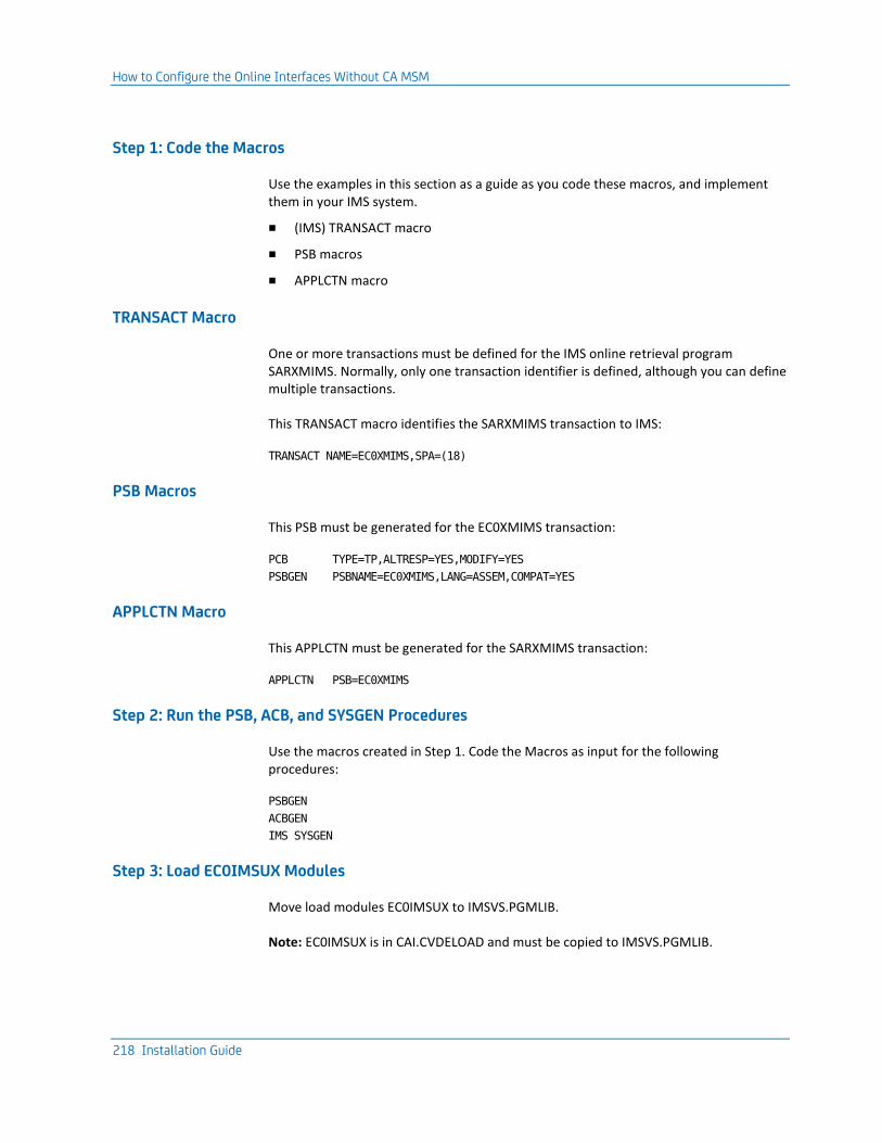
How to Configure the Online Interfaces Without CA MSM
218 Installation Guide
Step 1: Code the Macros
Use the examples in this section as a guide as you code these macros, and implement them in your IMS system.
■ (IMS) TRANSACT macro
■ PSB macros
■ APPLCTN macro
TRANSACT Macro
One or more transactions must be defined for the IMS online retrieval program SARXMIMS. Normally, only one transaction identifier is defined, although you can define multiple transactions.
This TRANSACT macro identifies the SARXMIMS transaction to IMS:
TRANSACT NAME=EC0XMIMS,SPA=(18)
PSB Macros
This PSB must be generated for the EC0XMIMS transaction:
PCB TYPE=TP,ALTRESP=YES,MODIFY=YES
PSBGEN PSBNAME=EC0XMIMS,LANG=ASSEM,COMPAT=YES
APPLCTN Macro
This APPLCTN must be generated for the SARXMIMS transaction:
APPLCTN PSB=EC0XMIMS
Step 2: Run the PSB, ACB, and SYSGEN Procedures
Use the macros created in Step 1. Code the Macros as input for the following procedures:
PSBGEN
ACBGEN
IMS SYSGEN
Step 3: Load EC0IMSUX Modules
Move load modules EC0IMSUX to IMSVS.PGMLIB.
Note: EC0IMSUX is in CAI.CVDELOAD and must be copied to IMSVS.PGMLIB.

How to Configure the Online Interfaces Without CA MSM
Chapter 10: Installing the Online Interfaces 219
IMS Notes (New Version)
Be aware of the following:
■ The new IMS/DC Transaction Program (EC0XMIMS) is a replacement for the older SARXMIMS program.
■ The EC0XMIMS does not need to be linkedited to the ASMTDLI interface program. The transaction is now conversational with a SPASIZE=18 (this can be adjusted).
■ If you use extended color, the SEGSIZE= may need to be increased, because extended color data streams can be a 50% increase over the monochrome data stream size.
To determine the SEGSIZE= value, take the terminal that uses the interface with the largest screen size, in bytes, and apply the following formula:
ROWS * COLS * 1.5 = SEGSIZE
For example, a 3278-5 with a 27 x 132 screen size would be (27 * 132 * 1.5) = 5346. If the SEGSIZE= is too small, the terminal user will get an RC= "A6" message indicating that a message insert failed.
IMS/DC Parameter Relationships
The cross-memory IMS/DC access involves up to three different address spaces as follows:
■ IMS/DC message processing region address spaces
The user's IMS/DC transaction resides here. If multiple IMS/DC users are processing concurrently (input being processed by the XMS system), a separate IMS/DC message region is used for each user.
IMS/DC can control the maximum number of IMS/DC transactions executing at one time.
■ The XMS support subtask
■ The subtask is started when the XMSSUB=YES input parameter is used when an XMS address space is started.
■ The subtask can be in a separate XMS address space or share the address space with XMS or VTAM sessions.
■ The XMSSUB=YES must only be used in an XMS address space with a default subsystem ID (SUBSYS=XMC0 or not specified).
■ If multiple XMS address spaces are started, only one can have the XMSSUB=YES specified.
Note: All IMS/DC, TSO/XMS, ISPF/XMS and CA Roscoe/XMS sessions share the same XMS subtask.
■ XMS address spaces
See the topic that follows.

How to Configure the Online Interfaces Without CA MSM
220 Installation Guide
IMS/DC Cross-Memory Notes
Be aware of the following:
■ The primary SARXMS region is to be started with the XMSSUB=YES parameter.
This region can be in a separate XMS address space or share the address space with XMS or VTAM sessions.
■ The XMSSUB=YES parameter must only be used in an XMS address space with a default subsystem ID (SUBSYS=XMC0 or not specified).
■ If multiple SARXMS regions are started, they must be started with XMSSUB=NO parameter.
Only the primary XMS region can have XMSSUB=YES specified.
■ The XMS regions must have the XMS=YES parameter to make it accessible.
■ The EBCXMCTR table must be assembled during installation to define the relationship between CA View and CA Deliver database high-level qualifiers. The table contains an EBCXMOPT macro to define initialization options and the EBCXMTRN macro for each CA View database transaction.
The EBCXMTRN macro also contains options for the specific database as follows:
■ SUBSYS= parameter of the cross-memory task
The parameter must match the SUBSYS= parameter specified in the EBCXMCTR table entry.
■ RECON=YES can be used to allow reconnection (after an ISPF terminal error) at the point of exit..
■ TIMEOUT= specifies how long ISPF is to wait for the XMS session to respond after the user enters input, in seconds.
We recommend a value as high as possible but not less than 240 (4 minutes).
To abort the XMS session and return the user to ISPF or the TSO command prompt, press the ATTN key.
Note:
■ The SUBMAX= parameter controls the number of user connections, not the USERMAX= parameter. USERMAX= only applies when you are using the subtask with the CICS interface.
■ For more information about the IMS online interface, see the chapter "Online Interface Administration" in the Reference Guide.
To control screen size manually, use these operands. The SNA query command can also be used to determine the device characteristics.
Enter For Terminal Type

How to Configure the Online Interfaces Without CA MSM
Chapter 10: Installing the Online Interfaces 221
Enter For Terminal Type
M2 3278-2 24 x 80 default screen size
M2H 3278-2 24 x 80 highlighting
M2X 3279-2 24 x 80 color highlighting
M2C 3279-2 24 x 80 color
M3 3278-3 32 x 80
M3H 3278-3 32 x 80 highlighting
M3X 3279-3 32 x 80 color highlighting
M3C 3279-3 32 x 80 color
M4 3278-4 43 x 80 highlighting
M4H 3278-4 43 x 80 highlighting
M4X 3279-4 43 x 80 color highlighting
M4C 3279-4 43 x 80 color
M5 3278-5 27 x 132
M5H 3278-5 27 x 132 highlighting
M5X 3279-5 27 x 132 color highlighting
M5C 3279-5 27 x 132 color
M6 3290 62 x 80
M6H 3290 62 x 80 highlighting
M7 3290 31 x 160
M7H 3290 31 x 160 highlighting
M8 3290 62 x 160
M8H 3290 62 x 160 highlighting
For other modifications to your system, see your VTAM programmer.

How to Configure the Online Interfaces Without CA MSM
222 Installation Guide
TSO, ISPF, CA Roscoe and Cross-Memory Address Spaces
TSO, ISPF, or CA Roscoe cross-memory access involves address spaces and subtasks as follows:
■ TSO or CA Roscoe address spaces
The TSO command, ISPF, or CA Roscoe application program resides here. If ISPF/XMS is being used with ISPF split-screen active, up to two sessions can be executing at the same time, to the same database, or different databases.
■ XMS Support Subtask
This subtask is started when XMSSUB=YES input parameter is used when starting an XMS address space. The subtask can be in a separate XMS address space, or it can share the address space with XMS or VTAM sessions.
– The XMSSUB=YES parameter must only be used in an XMS address space with a default subsystem ID (SUBSYS=XMC0 or not specified).
– If multiple XMS address spaces are started, only one can have the XMSSUB=YES specified.
Note: All IMS/DC, TSO/XMS, ISPF/XMS, and CA Roscoe/XMS sessions share the same XMS subtask.
■ XMS address spaces
The XMS regions must have the XMS=YES parameter to make them accessible.
Note: The SUBSYS= parameter must match the EC0XMCTR table entry for the database.
Multiple address spaces can be used if needed.
Multiple Cross-Memory Region Requirements
Be aware of the following:
■ All cross-memory regions started under the same SUBSYS ID are chained together.
■ The REGIONID positional parameter is the first value of the PARM= statement for the cross-memory task.
You must specify a different REGIONID for each started cross-memory region.
■ The value of the XMSSUB parameter for the primary region depends on the type of XMS region you are defining.
See this table for the XMSSUB values. Specify XMSSUB=NO for all other started regions.
Primary Region Type XMSSUB Recommendation
Non-VTAM Must use XMSSUB=YES

How to Configure the Online Interfaces Without CA MSM
Chapter 10: Installing the Online Interfaces 223
Primary Region Type XMSSUB Recommendation
CICS Recommend using XMSSUB=YES
VTAM-only XMSSUB=NO use allowed
Note:
■ You must specify XMS=YES for all other started regions except for VTAM-only regions where XMS=NO is permissible.
■ Each VTAM cross-memory region requires a different applid. The applid is specified using the SARAPPL= parameter.
■ Each VTAM cross-memory region requires VTAMPASS=YES.
■ The VTAM administrator must verify that each VTAM cross memory applid has this setting:
AUTH=(PASS,ACO)
Prepare to Start the Cross Memory Task
Follow these steps:
1. (Optional) Add the start procedure to PROCLIB for the cross-memory online task.
2. (Optional) Modify, assemble, and link edit the EC0XMCTR module.
3. Define security requirements for CA Top Secret Security (eTrust CA-Top Secret).
Start the Cross Memory Task
Start the XMS CBROSDRV procedure.


Chapter 11: Installing the Features 225
Chapter 11: Installing the Features
This section explains how to install the various features of CA View.
This section contains the following topics:
Install ERO (see page 225) Install the VTAM Print Option (see page 226) Install the Interface with Print Management (see page 228) Install the Interface with ACIF (AFP Report Archival) (see page 228) Install a CA View PDF Archiver (see page 238) Install the Viewing Option Interface (see page 247) Install the Global Subsystem Interface (see page 248) Install the Optical Disk Interface (see page 248) Install the Extended Access Server for Tape and Robotics (see page 248) Install the FSS Collector (see page 249) Install the EMC Centera Disk Option (see page 259)
Install ERO
The ERO (Expanded Retention Option) option allows you to specify particular SYSOUTs as having expanded retention, beyond the expiration for selected reports. These SYSOUTs can be given separate retention criteria. Read these instructions thoroughly before installing the option.
Step 1: Set the ERO Initialization Parameters
For more information about the instructions and a discussion of the initialization parameters available for the ERO, see the following chapters in the Reference Guide:
■ "Initialization Parameters"
■ "Configuring"
■ "Expanded Retention Option"
Record the expanded retention initialization parameter values on the Initialization Parameter Worksheet in the appendix "Installation Worksheets."

Install the VTAM Print Option
226 Installation Guide
Step 2: (Optional) Create the ERO Table Statements
The ERO table is a PDS member with multiple control statements.
If you want selective permanent archival of SYSOUT, place the control statements in a card image data set and include a SARPATAB DD statement for the data set in the archival started task JCL.
Record the name of your expanded retention control statement data set next to the SARPATAB ddname on the Archival Started Task Worksheet.
Install the VTAM Print Option
The following steps are required to install the VTAM print option. Each step is explained in detail in the sections that follow.
1. Define the application program to VTAM.
2. (Optional) Verify the CICS table entries for printers shared with CICS.
3. Set the VTAM print option initialization parameters.
Configuration Requirements
The VTAM print option is designed for an IBM 3287 printer configuration with LU type = 3. Consult your VTAM systems programmer if necessary.

Install the VTAM Print Option
Chapter 11: Installing the Features 227
Step 1: Define the Application Program to VTAM
Add the following application program definition to SYS1.VTAMLST:
name VBUILD TYPE=APPL
CCCC0001 APPL AUTH=(ACQ)
CCCC0002 APPL AUTH=(ACQ)
CCCC0003 APPL AUTH=(ACQ)
CCCC0004 APPL AUTH=(ACQ)
.
.
CCCCnnnn APPL AUTH=(ACQ)
where CCCCnnnn values are as follows:
CCCC
Is the value in the VPRTAPPL initialization parameter
nnnn
Is a sequential number starting at 0001 which specifies the total number of printers being used simultaneously by all concurrent online users and batch jobs
Step 2: (Optional) Verify the CICS Table Entries
Ensure that you have the proper CICS table entries for printers shared with CICS. If you are sharing a printer with CICS, the CICS TCT must have a parameter of the following:
RELREQ=(YES,YES)
or an equivalent RDO setting:
RELREQ ---->YES
DISCREQ --->YES
Step 3: Set the VTAM Print Option Initialization Parameters
If the default VTAM print option initialization parameters are not suitable for your site, you can define your own specifications.
Note: For information about the initialization parameters, see the chapters "Configuring" and "Initialization Parameters" in the Reference Guide.
VTAM print option parameters have the prefix VPRT.
Record the VTAM print option initialization parameter values on the Initialization Parameter Worksheet in the appendix "Installation Worksheets."

Install the Interface with Print Management
228 Installation Guide
Install the Interface with Print Management
The CA View-to-CA Spool interface allows you to output data directly into the CA Spool database rather than having to pass it through the JES SPOOL, which reduces processing time significantly.
The CA Spool interface option is installed during SMP/E RECEIVE and APPLY.
CA Spool Requirement
For the interface to work properly, you must have CA Spool r2.0 (or later).
Initialization Parameters
Follow these steps:
■ Specify initialization parameter CMASPOOL.
■ Evaluate all other initialization parameters that begin with CMA.
Record the CA Spool initialization parameter values on the Initialization Parameter Worksheet.
Install the Interface with ACIF (AFP Report Archival)
The following steps are required to install the CA View ACIF Interface Option. Each step is explained in detail in the following sections.
1. Define JES2 initialization statements, for JES2 sites.
2. Define JES3 initialization statements, for JES3 sites.

Install the Interface with ACIF (AFP Report Archival)
Chapter 11: Installing the Features 229
3. Define a CA View ACIF archiver PROC.
4. Define CA View FSA device control statements.
Note:
■ For more information about archiving AFP reports to CA View, ACIF control statements, and a complete example of the process, see the "Archival" chapter in the Reference Guide.
■ ACIF indexing on AFP reports requires a functional subsystem definition (FSS).
FSS printers can be installed under JES2, JES3, or CA Spool. If you are planning to use CA Spool to host the ACIF FSS collector, see the CA Spool documentation for information about how to install and operate FSS printers under CA Spool.
After you have defined the CA View FSS printer to CA Spool, skip Step 1 and Step 2 and continue with Step 3.
Step 1: Define JES2 Initialization Statements
This step provides a sample FSS definition, JES2 initialization statements, and a JES2 print statement.
Use the sample FSS definition as a guide and place the JES2 initialization statements in the JES2 PARMLIB or in a SYS1.PARMLIB.
Note: For more information about JES2 statements and a description of all of the FSSDEF parameters, see the IBM JES2 Initialization and Tuning Reference for your operating system.
Sample FSS Definition
This example shows JES2 statements for a CA View ACIF archiver:
FSSDEF(VBRMFSSS)PROC=CBRMSFSS, AUTOSTOP=Y PRINTER(10)FSS=VBRMFSSS,
PRMODE=(ACIF),
MODE=FSS,
CLASS=AJQ,
DRAIN,
ROUTECDE=(R10),
NOSEP,
WS=(PRM,Q,R)
A sample PROC for this procedure is in CAI.CVDEPROC.

Install the Interface with ACIF (AFP Report Archival)
230 Installation Guide
JES2 Initialization Statements
The FSSDEF initialization statement defines an FSS to JES2. The following explanations of the JES2 initialization statements are used in the definition of a CA View ACIF archiver. The syntax is as follows:
FSSDEF Statement
The FSSDEF statement is associated with one or more PRTnnnn statements that define each archiver FSA. The FSSDEF initialization parameter is optional, but recommended. If it is omitted, JES2 generates a default for that archiver.
The FSSDEF statement contains the following parameters:
FSSNAME
Defines the unique 1- to 8-character name of an FSS.
When you start the first CA View ACIF archiver that has an FSA definition for that FSS, an FSS address space is created for the archiver. The CA View ACIF interface manages this FSS and the archival FSA for the first CA View ACIF archiver. If you start a second archiver with an FSA definition for the same FSS, the CA View ACIF interface manages a separate FSA for the second archival FSA in that FSS.
Under JES2, each FSS can support a maximum of 24 FSAs. The actual number of FSAs per FSS depends on several factors, such as the size of resources used in the print jobs and the available virtual storage.
This parameter is required.
PROC
Specifies a procedure for starting the CA View ACIF FSS.
The procedure (which must be defined before this FSS is started) is a member of either SYS1.PROCLIB or a library concatenated to SYS1.PROCLIB. Different FSSDEF initialization parameters can refer to the same startup procedure.
HASPFSSM
Defines the 1- to 8-character name of the load module that is loaded into the PSF FSS address space.
This load module contains the various JES2-supplied FSI service routines. For CA View ACIF, specify the default value (HASPFSSM = HASPFSSM).
JES2 PRINTER(nnnn) Statement
A PRINTER(nnnn) statement (required to define each FSA) is associated with an FSSDEF statement. Each archival FSA must have a unique PRINTER(nnnn) name. This unique PRINTER(nnnn) must match the label on the device parameter DD statement in the procedure for starting the CA View ACIF FSS.
PRINTER(nnnn)
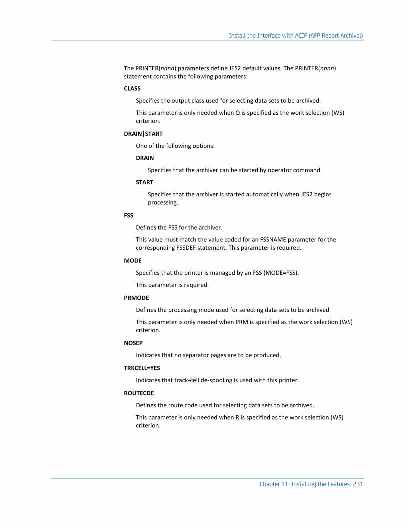
Install the Interface with ACIF (AFP Report Archival)
Chapter 11: Installing the Features 231
The PRINTER(nnnn) parameters define JES2 default values. The PRINTER(nnnn) statement contains the following parameters:
CLASS
Specifies the output class used for selecting data sets to be archived.
This parameter is only needed when Q is specified as the work selection (WS) criterion.
DRAIN|START
One of the following options:
DRAIN
Specifies that the archiver can be started by operator command.
START
Specifies that the archiver is started automatically when JES2 begins processing.
FSS
Defines the FSS for the archiver.
This value must match the value coded for an FSSNAME parameter for the corresponding FSSDEF statement. This parameter is required.
MODE
Specifies that the printer is managed by an FSS (MODE=FSS).
This parameter is required.
PRMODE
Defines the processing mode used for selecting data sets to be archived
This parameter is only needed when PRM is specified as the work selection (WS) criterion.
NOSEP
Indicates that no separator pages are to be produced.
TRKCELL=YES
Indicates that track-cell de-spooling is used with this printer.
ROUTECDE
Defines the route code used for selecting data sets to be archived.
This parameter is only needed when R is specified as the work selection (WS) criterion.

Install the Interface with ACIF (AFP Report Archival)
232 Installation Guide
FORMS
Defines the form identifier used for selecting data sets for archival.
This parameter is only needed when F is specified as the work selection (WS) criterion.
WRITER
Defines the writer name used for selecting data sets for archival.
This parameter is only needed when W is specified as the work selection (WS) criterion.
WS
Defines the work selection criteria for archival.
Examples of WS are:
WS=(PRM),PRMODE=ACIF
Selects all data sets having a process mode of ACIF.
WS=(Q),CLASS=S
Selects all data sets having a SYSOUT class of S.
Step 2: Define JES3 Initialization Statements
This step provides a sample FSS definition, JES3 initialization statements, and a JES3 device statement.
Use the sample FSS definition as a guide and place the JES3 initialization statements in a SYS1.PARMLIB.
Note: For more information about JES3 statements, see the IBM JES3 Initialization and Tuning Reference for your operating system.
Sample FSS Definition
This example shows JES3 statements for a CA View ACIF archiver.
Place these statements in SYS1.PARMLIB.
FSSDEF,TYPE=WTR,FSSNAME=VBRMFSSS,PNAME=CVRMSFSS
DEVICE,JNAME=PRT1,DTYPE=SARACIF,MODE=FSS,
PM=ACIF,WS=(PM),HEADER=NO
A sample PROC is in CAI.CVDEPROC.

Install the Interface with ACIF (AFP Report Archival)
Chapter 11: Installing the Features 233
JES3 Initialization Statements
The FSSDEF initialization parameter defines an FSS to JES3. The following explanations of the JES3 initialization statements are used in the definition of the CA View ACIF archivers. The syntax is as follows:
FSSDEF Statement
The FSSDEF initialization statement is optional, but recommended. If it is omitted, JES3 generates a default for that archiver. The FSSDEF statement can contain the following parameters:
TYPE
Specifies that the FSS is an output writer for deferred printing (TYPE=WTR).
This parameter is required.
FSSNAME
Defines the unique 1- to 8-character name of an FSS.
This parameter is required.
PNAME
Defines a procedure for starting a specific CA View ACIF FSS.
The procedure (which must be defined before that FSS is started) is a member of the procedure library defined by the STCPROC parameter of the STANDARDS statement, or of the IATPLBST procedure library (the default). Different FSSDEF initialization parameters can refer to the same startup procedure.
SYSTEM
The JES3 processor on which the FSS runs.
The name must be the same as specified on the NAME parameter of the MAINPROC statement for the processor.
TERM = YES|NO
YES specifies that the FSS is terminated if the JES3 global address space terminates by a *RETURN or *DUMP operator command.
JES3 Device Statement
A DEVICE statement is required for each archival FSA. The DEVICE parameters create JES3 default values that are used unless other values are specified in the JCL application program. The DEVICE statement can contain the following parameters:
DTYPE
Indicates a parameter that is ignored by CA View ACIF, but must be specified.
Any name can be used.

Install the Interface with ACIF (AFP Report Archival)
234 Installation Guide
FSSNAME
Specifies a unique FSS for this CA View ACIF archiver DEVICE statement.
The value must match the value coded for the FSSNAME parameter in the corresponding FSSDEF statement. This parameter is required.
HEADER=NO
Indicates that no data set header pages are printed.
JNAME
Indicates the 1- to 8-character name of the CA View ACIF archiver FSA.
Each archiver FSA must have a unique JNAME. This JNAME must correspond to the name on the DEVICE DD statement in the procedure for starting the CA View ACIF FSS. This parameter is required.
JUNIT
Specifies the JUNIT = (,,,OFF) for CA View ACIF archival.
MODE
Indicates that the archiver is managed by an FSS.
This parameter is required.
WS=()
Defines the work selection criteria.
The options are:
CL
Specifies selection by SYSOUT class.
PM
Specifies selection by process mode.
Step 3: Define an ACIF Archiver PROC
This PROC specifies initialization parameters and libraries that contain system and installation resources for the CA View ACIF archiver.
Before starting a CA View ACIF archiver, ensure you have a cataloged startup PROC in SYS1.PROCLIB or a procedure library concatenated to it. Use the sample JCL for CA View ACIF startup procedure in the next section as a guide.

Install the Interface with ACIF (AFP Report Archival)
Chapter 11: Installing the Features 235
Sample JCL for an ACIF Startup PROC
//VIEWFSS EXEC PGM=SARFSS,TIME=1440,REGION=2M
//STEPLIB DD DISP=SHR,DSN=CAI.CVDELOAD
DD DISP=SHR,DSN=ACIF.LOADLIB
//SYSUDUMP DD SYSOUT=A
//SARINDEX DD DISP=SHR,DSN=CAI.CVDEOPTN
//PRT68 DD DISP=SHR,DSN=CAI.CVDEOPTN(PRT68)
//SARLOG DD SYSOUT=A
Note: A sample PROC is in CAI.CVDEPROC.
The following explains the statements in the example:
STEPLIB DD: authorization
Defines that the CA View CAI.CVDELOAD and the ACIF load library (containing the APKACIF utility) must be in an authorized STEPLIB concatenation, or in a LNKLSTxx library.
SARINDEX DD
Specifies the PDS members containing the ACIF control statements.
For information about coding these statements, see the chapter "Archival" in the Reference Guide.
PRTnnnn DD statements
Contains parameters for each CA View ACIF archive.
The ddname must match that of the corresponding JES2 PRINTER(nnnn) device, or JES3 JNAME value. Multiple PRTnnnn DD statements can be specified for each CA View ACIF archive.
(Optional) SARLOG DD
Specifies that CA View ACIF messages are written to it. These messages are documented in the IBM manual, Advanced Function Presentation, Conversion and Indexing Facility Application Programming Guide.
Step 4: Define FSA Device Control Statements
CA View FSA device control statements are defined in the CA View ACIF FSS start procedure with PRTnnnn DD statements. Each PRTnnnn DD statement must have a JES device initialization parameter statement (see Step 1: Define JES2 Initialization Statements and Step 2: Define JES3 Initialization Statements earlier in this chapter).
Use the sample ACIF device control statements as a guide. Place these statements in a product PARMLIB or in SYS1.PARMLIB.

Install the Interface with ACIF (AFP Report Archival)
236 Installation Guide
Coding the Statements
Information about the coding rules of the FSA Device Control Statements is documented in the IBM manual, Advanced Function Presentation, Conversion and Indexing Facility Application Programming Guide.
Sample ACIF Device Control Statements
This example shows the CA View ACIF device control statements. Place these statements in a program product PARMLIB, or SYS1.PARMLIB.
TYPE=ACIF
NAME=highlevelindex.view.database
ARCHMSG=LOG
NOGRPID=
CHARS=(GT15,GS15,GU15,GU15)
FDEFLIB=SYS1.FDEFLIB,USER.AFPLIB
FONTLIB=SYS1.FONTLIBB,USER.AFPLIB
FORMDEF=A10110
OVLYLIB=SYS1.OVERLIB,USER.AFPLIB
PAGEDEF=V06683
PDEFLIB=SYS1.PDEFLIB,USER.AFPLIB
PSEGLIB=SYS1.PSEGLIB,USER.AFPLIB
NEWCLASS=T
NEWDEST=
NEWFORM=
NEWPRMOD=
NEWWTR=
The following list describes the CA View ACIF device control statements:
TYPE=ACIF
Indicates that the FSA is identified as a ACIF archive.
Code TYPE=ACIF as the first statement.
NAME=
Specifies the high-level name of the CA View database.
ARCHMSG=YES|NO|LOG
Specifies whether to issue a SARACI22 message every time that CA View archives a SYSOUT data set. LOG specifies that no WTO console messages are produced (only SARLOG messages are created, if SARLOG is present).

Install the Interface with ACIF (AFP Report Archival)
Chapter 11: Installing the Features 237
NOGRPID=PROCESS | FAIL
Specifies the action to be taken if the SARINDEX Library does not contain a member identified by the GROUPID= parameter on the //name OUTPUT JCL statement..
PROCESS =
Issues the message SARACI06, and archive the Sysout with the default specifications.
FAIL=
Issues the message SARACI06, mark the report in CA View as 'ACIF' in the Exception Code Field, the SARACI06 with other APKACIF messages are stored in the CA View report, and the JES 'Release/Hold' command is executed against the Sysout.
Default: PROCESS.
CHARS=
Specifies up to four different default font names.
A font name must be from 1–4 alphanumeric or national characters.
FDEFLIB
Specifies up to eight form definition libraries.
FONTLIB
Specifies up to eight font libraries.
FORMDEF
Specifies the default form definition.
OVLYLIB
Specifies up to eight overlay libraries.
PAGEDEF
Specifies the default page definitions.
PDEFLIB
Specifies up to eight page definition libraries.
PSEGLIB
Specifies up to eight page-segment libraries.

Install a CA View PDF Archiver
238 Installation Guide
NEWCLASS
Specifies the new SYSOUT CLASS under which to archive.
This class becomes the default SYSOUT CLASS for reprinting. It is not used for archival data created by CA Deliver or CA View systems extensions.
The value of this parameter, if specified, becomes the class value for the report in the CA View database. Reprint Class translation, as specified by the SARINIT parameter NEWCLSL, can still occur whether NEWCLASS is specified, if the report is not a CA Deliver report.
NEWDEST
Specifies the new SYSOUT DEST under which to archive.
This DEST becomes the default SYSOUT DEST for reprinting. It is not used for archival data created by CA Deliver or CA View systems extensions.
The value of this parameter, if specified, becomes the destination value for the report in the CA View database. The SARINIT parameter NEWDEST, if specified, overrides this parameter when the report is reprinted.
NEWFORM
Specifies the new SYSOUT FORM under which to archive.
This form becomes the default SYSOUT FORM for reprinting. It is not used for archival data created by CA Deliver or CA View systems extensions.
The value of this parameter, if specified, becomes the forms value for the report in the CA View database. The SARINIT parameter NEWFORM, if specified, overrides this parameter when the report is reprinted.
NEWPRMOD
Specifies the new SYSOUT process mode under which to archive.
This mode becomes the default SYSOUT process mode for reprinting. It is not used for archival data created by CA Deliver or CA View systems extensions.
NEWWTR
Specifies the new SYSOUT WRITER name under which to archive.
This name becomes the default SYSOUT WRITER name for reprinting. It is not used for archival data created by CA Deliver or CA View systems extensions.
Install a CA View PDF Archiver
The following steps are required to install the CA View PDF Archiver. Each step is explained in detail in the following sections.
1. (For JES2 sites) Define JES2 initialization statements.
2. (For JES3 sites) Define JES3 initialization statements.

Install a CA View PDF Archiver
Chapter 11: Installing the Features 239
3. Define a CA View PDF archiver PROC.
4. Define CA View FSA device control statements.
Note: For more information about archiving PDF reports to CA View, control statements and a complete example of the process, see the chapter "Archival" in the Reference Guide.
PDF indexing/archiver requires a functional subsystem definition (FSS).
Note: FSS printers can be installed under JES2, JES3, or CA Spool. If you are planning to use CA Spool to host the PDF FSS collector, see the CA Spool documentation for more information about how to install and operate FSS printers under CA Spool.
After you have defined the CA View FSS printer to CA Spool, Skip Steps 1 and 2 and continue with Step 3 in this section.
Step 1: Define JES2 Initialization Statements
This step provides a sample FSS definition, JES2 initialization statements, and a JES2 print statement.
Use the sample FSS definition as a guide and place the JES2 initialization statements in the JES2 PARMLIB or in a SYS1.PARMLIB.
Note: For more information about JES2 statements and a description of all of the FSSDEF parameters, see the IBM JES2 Initialization and Tuning Reference for your operating system.
Sample FSS Definition
This example shows JES3 statements for a CA View PDF archiver.
Place these statements in SYS1.PARMLIB.
FSSDEF,TYPE=WTR,FSSNAME=FSSSAR,PNAME=PDFCOLCT
DEVICE,JNAME=PRT1,DTYPE=SARPDF,MODE=FSS,
PM=PDFC,WS=(PM),HEADER=NO
A sample PROC is in CAI.CVDEPROC.

Install a CA View PDF Archiver
240 Installation Guide
JES2 Initialization Statements
The FSSDEF initialization statement defines an FSS to JES2.The following explains the JES2 initialization statements used in the definition of a CA View PDF archiver. The syntax is as follows:
FSSDEF Statement
The FSSDEF statement is associated with one or more PRTnnnn statements that define each archiver FSA. The FSSDEF initialization parameter is optional, but recommended. If it is omitted, JES2 generates a default for that archiver.
The FSSDEF statement contains the following parameters:
FSSNAME
Defines the unique 1- to 8-character name of an FSS,
When you start the first CA View PDF archiver that has an FSA definition for that FSS, an FSS address space is created for the archiver. The CA View PDF interface manages this FSS and the archival FSA for the first CA View PDF archiver. If you start a second archiver with an FSA definition for the same FSS, the CA View PDF interface manages a separate FSA for the second archival FSA in that FSS.
Under JES2, each FSS can support a maximum of 24 FSAs. The actual number of FSAs per FSS depends on several factors, such as the size of resources used in the print jobs and the available virtual storage.
This parameter is required.
PROC
Defines a procedure for starting the CA View PDF FSS.
The procedure (which must be defined before this FSS is started) is a member of either SYS1.PROCLIB or a library concatenated to SYS1.PROCLIB. Different FSSDEF initialization parameters can refer to the same startup procedure.
HASPFSSM
Defines the 1- to 8-character name of the load module that is loaded into the PSF FSS address space.
This load module contains the various JES2-supplied FSI service routines. For CA View PDF, specify the default value (HASPFSSM = HASPFSSM).
JES2 PRINTER(nnnn) Statement
A PRINTER(nnnn) statement (required to define each FSA) is associated with an FSSDEF statement. Each archival FSA should have a unique PRINTER(nnnn) name. This unique PRINTER(nnnn) must match the label on the device parameter DD statement in the procedure for starting the CA View PDF FSS.
PRINTER(nnnn)

Install a CA View PDF Archiver
Chapter 11: Installing the Features 241
The PRINTER(nnnn) parameters define JES2 default values. The PRINTER(nnnn) statement contains the following parameters:
CLASS
Defines the output class used for selecting data sets to be archived.
This parameter is only needed when Q is specified as the work selection (WS) criterion.
DRAIN|START
One of the following:
DRAIN
Specifies that the archiver can be started by operator command.
START
Specifies that the archiver is started automatically when JES2 begins processing.
FSS
Defines the FSS for the archiver.
This value must match the value coded for an FSSNAME parameter for the corresponding FSSDEF statement. This parameter is required.
MODE
Indicates that the printer is managed by an FSS (MODE=FSS).
This parameter is required.
PRMODE
Defines the processing mode used for selecting data sets to be archived.
This parameter is only needed when PRM is specified as the work selection (WS) criterion.
NOSEP
Specifies that no separator pages are produced.
TRKCELL=YES
Specifies that track-cell de-spooling is used with this printer.
ROUTECDE
Defines the route code used for selecting data sets to be archived.
This parameter is only needed when R is specified as the work selection (WS) criterion.

Install a CA View PDF Archiver
242 Installation Guide
FORMS
Defines the form identifier used for selecting data sets for archival.
This parameter is only needed when F is specified as the work selection (WS) criterion.
WRITER
Defines the writer name used for selecting data sets for archival.
This parameter is only needed when W is specified as the work selection (WS) criterion.
WS
Defines the work selection criteria for archival.
Examples of WS are:
WS=(PRM),PRMODE=PDFC
Selects all data sets having a process mode of PDF.
WS=(Q),CLASS=S
Selects all data sets having a SYSOUT class of S.
Step 2: Define JES3 Initialization Statements
This step provides a sample FSS definition, JES3 initialization statements, and a JES3 device statement.
Use the sample FSS definition as a guide and place the JES3 initialization statements in a SYS1.PARMLIB.
Note: For more information about JES3 statements, see the IBM JES3 Initialization and Tuning Reference for your operating system.
Sample FSS Definition
This example shows JES3 statements for a CA View PDF archiver.
Place these statements in SYS1.PARMLIB.
FSSDEF,TYPE=WTR,FSSNAME=FSSSAR,PNAME=PDFCOLCT
DEVICE,JNAME=PRT1,DTYPE=SARPDF,MODE=FSS,
PM=PDFC,WS=(PM),HEADER=NO
A sample PROC is in CAI.CVDEPROC.

Install a CA View PDF Archiver
Chapter 11: Installing the Features 243
JES3 Initialization Statements
The FSSDEF initialization parameter defines an FSS to JES3. The following explains the JES3 initialization statements used in the definition of the CA View PDF archivers. The syntax is as follows:
FSSDEF Statement
The FSSDEF initialization statement is optional, but recommended. If it is omitted, JES3 generates a default for that archiver. The FSSDEF statement can contain the following parameters:
TYPE
Specifies that the FSS is an output writer for deferred printing (TYPE=WTR).
This parameter is required.
FSSNAME
The unique 1- to 8-character name of an FSS.
This parameter is required.
PNAME
A procedure for starting a specific CA View PDF FSS.
The procedure (which must be defined before that FSS is started) is a member of the procedure library defined by the STCPROC parameter of the STANDARDS statement, or of the IATPLBST procedure library (the default). Different FSSDEF initialization parameters can refer to the same startup procedure.
SYSTEM
The JES3 processor on which the FSS runs.
The name must be the same as specified on the NAME parameter of the MAINPROC statement for the processor.
TERM = YES|NO
YES specifies that the FSS is terminated if the JES3 global address space terminates by a *RETURN or *DUMP operator command.
JES3 Device Statement
A DEVICE statement is required for each archival FSA. The DEVICE parameters create JES3 default values that are used unless other values are specified in the JCL application program. The DEVICE statement can contain the following parameters:
DTYPE
Defines a parameter that is ignored by CA View PDF, but must be specified.
Any name can be used.

Install a CA View PDF Archiver
244 Installation Guide
FSSNAME
Specifies a unique FSS for this CA View PDF archiver DEVICE statement.
The value must match the value coded for the FSSNAME parameter in the corresponding FSSDEF statement. This parameter is required.
HEADER=NO
Indicates that no data set header pages are printed.
JNAME
Specifies the 1- to 8-character name of the CA View PDF archiver FSA.
Each archiver FSA must have a unique JNAME. This JNAME must correspond to the name on the DEVICE DD statement in the procedure for starting the CA View PDS FSS. This parameter is required.
JUNIT
Specifies the JUNIT = (,,,OFF) for CA View PDF archival.
MODE
Indicates that the archiver is managed by an FSS.
This parameter is required.
WS=()
The work selection criteria.
The options are:
PM
Specifies selection by SYSOUT class.
CL
Specifies selection by process mode.
Step 3: Define a PDF Archiver PROC
This PROC specifies initialization parameters and libraries that contain system and installation resources for the CA View PDF archiver.
Before starting a CA View PDF archiver, ensure you have a cataloged startup PROC in SYS1.PROCLIB or a procedure library concatenated to it. Use the sample JCL for CA View PDF startup procedure in the next section as a guide.

Install a CA View PDF Archiver
Chapter 11: Installing the Features 245
Sample JCL for an PDF Startup PROC
//PDFCOLCT PROC
//PDFCOLCT EXEC PGM=SARFSS,TIME=1440,
// REGION=2M
//STEPLIB DD DSN=CAI.CVDELOAD,DISP=SHR
//SYSUDUMP DD SYSOUT=A
//PDFINDEX DD DSN=VIEW.PDFINDEX,DISP=SHR
//PRT11 DD DSN=CAI.CVDEOPTN(PRT11),DISP=SHR
//SARLOG DD SYSOUT=A
//PDFREPRT DD SYSOUT=X <---- DEFAULT PDF REPORT DATASET
//PDFTRACE DD SYSOUT=X <---- DEFAULT PDF TRACE REPORT DATASET
//SARLOG DD SYSOUT=X <---- DEFAULT SARLOG OUTPUT.
//SYSOUT DD SYSOUT=X <-- - Informationary messages from PDF DEFLATE.
//STDERR DD SYSOUT=X
// PEND
//VIEWPDF EXEC PROC=PDFCOLCT
Note: A sample PROC is in CAI.CVDEPROC.
The following explains the statements in the example:
STEPLIB DD: authorization
Defines the CA View CAI.CVDELOAD must be in an authorized STEPLIB concatenation, or in a LNKLSTxx library.
PDFINDEX DD
Specifies the PDS members containing the PDF control statements.
For information about coding these statements, see the chapter "Archival" in the Reference Guide.
PRTnnnn DD statements
Contains parameters for each CA View PDF archive.
The ddname must match that of the corresponding JES2 PRINTER(nnnn) device, or JES3 JNAME value. Multiple PRTnnnn DD statements can be specified for each CA View PDF archive.
SARLOG DD
Specifies that CA View PDF messages are written to it. These messages are documented in the Message Guide. The SARLOG DD statement is optional.

Install a CA View PDF Archiver
246 Installation Guide
Step 4: Define FSA Device Control Statements
CA View FSA device control statements are defined in the CA View PDF FSS start procedure with PRTnnnn DD statements. Each PRTnnnn DD statement must have a JES device initialization parameter statement (see Step 1: Define JES2 Initialization Statements and Step 2: Define JES3 Initialization Statements earlier in this chapter).
Use the sample PDF device control statements as a guide. Place these statements in a product PARMLIB or in SYS1.PARMLIB.
Code the Statements
For more information about the coding rules of the FSA device control statements, see the IBM manual, Advanced Function Presentation, Conversion and Indexing Facility Application Programming Guide.
Sample PDF Device Control Statements
TYPE=PDF
ARCHMSG=LOG
NAME=CA VIEW.SAR.DATABASE.TO.RECIEVE.INTO
The following list describes the CA View PDF device control statements:
TYPE=PDF
Indicates that the FSA is identified as a PDF archive.
Code TYPE=PDF as the first statement.
NAME=
Specifies the high-level name of the CA View database.
ARCHMSG=YES|NO|LOG
Specifies whether to issue a CAHPDF01I message every time that CA View archives a SYSOUT data set. LOG specifies that no WTO console messages are produced (only SARLOG messages are created, if SARLOG is present).
NEWCLASS
Specifies the new SYSOUT CLASS under which to archive.
This class becomes the default SYSOUT CLASS for reprinting. It is not used for archival data created by CA Deliver or CA View systems extensions.
The value of this parameter, if specified, becomes the class value for the report in the CA View database. Reprint Class translation, as specified by the SARINIT parameter NEWCLSL, can still occur whether NEWCLASS is specified, if the report is not a CA Deliver report.
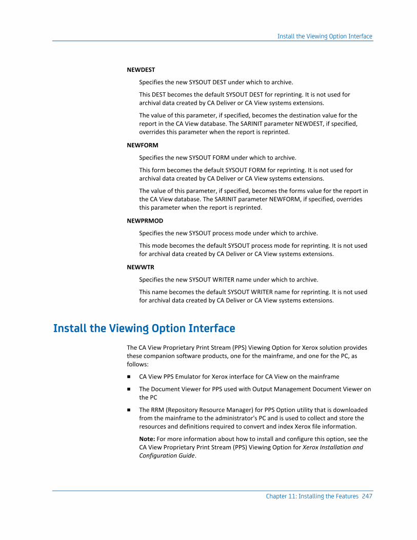
Install the Viewing Option Interface
Chapter 11: Installing the Features 247
NEWDEST
Specifies the new SYSOUT DEST under which to archive.
This DEST becomes the default SYSOUT DEST for reprinting. It is not used for archival data created by CA Deliver or CA View systems extensions.
The value of this parameter, if specified, becomes the destination value for the report in the CA View database. The SARINIT parameter NEWDEST, if specified, overrides this parameter when the report is reprinted.
NEWFORM
Specifies the new SYSOUT FORM under which to archive.
This form becomes the default SYSOUT FORM for reprinting. It is not used for archival data created by CA Deliver or CA View systems extensions.
The value of this parameter, if specified, becomes the forms value for the report in the CA View database. The SARINIT parameter NEWFORM, if specified, overrides this parameter when the report is reprinted.
NEWPRMOD
Specifies the new SYSOUT process mode under which to archive.
This mode becomes the default SYSOUT process mode for reprinting. It is not used for archival data created by CA Deliver or CA View systems extensions.
NEWWTR
Specifies the new SYSOUT WRITER name under which to archive.
This name becomes the default SYSOUT WRITER name for reprinting. It is not used for archival data created by CA Deliver or CA View systems extensions.
Install the Viewing Option Interface
The CA View Proprietary Print Stream (PPS) Viewing Option for Xerox solution provides these companion software products, one for the mainframe, and one for the PC, as follows:
■ CA View PPS Emulator for Xerox interface for CA View on the mainframe
■ The Document Viewer for PPS used with Output Management Document Viewer on the PC
■ The RRM (Repository Resource Manager) for PPS Option utility that is downloaded from the mainframe to the administrator's PC and is used to collect and store the resources and definitions required to convert and index Xerox file information.
Note: For more information about how to install and configure this option, see the CA View Proprietary Print Stream (PPS) Viewing Option for Xerox Installation and Configuration Guide.

Install the Global Subsystem Interface
248 Installation Guide
Install the Global Subsystem Interface
The CA GSS (Global Subsystem) interface allows you to write REXX routines to have other CA products invoke the SARBCH, the batch processing program for CA View. You can also have SARBCH invoke other CA products.
SARBCH can be used for many administrative functions, such as:
■ Adding, deleting, or modifying user definitions
■ Printing reports
■ Producing a listing of users or reports
Note: For more information about the implementation of CA GSS, see the chapter "Batch Processing" in the Reference Guide.
Perform each of the following steps to install the GSS interface:
1. (Optional) Verify that you have CA GSS installed on your system.
2. (Not SPF) Edit the data set and member that is allocated to the PARMLIB DDNAME in the GSS that is running on your system.
To add CA View to the address space, add the line:
ADDRESS XPVIEW SARINTF
3. (Optional) Add the CA View load library to the concatenation of the CA GSS procedure.
4. (Optional) Restart CA GSS.
Install the Optical Disk Interface
For more information about how to configure the optical disk interface, see the chapter "Using the Optical Disk Interface" in the Reference Guide.
Install the Extended Access Server for Tape and Robotics
For information about how to implement and use the extended access server for tape and robotics, see the chapter "Configuring" in the Reference Guide.

Install the FSS Collector
Chapter 11: Installing the Features 249
Install the FSS Collector
The CA View FSS (Functional Subsystem) Collector for JES report archival is an option designed to supplement the CA View archival task. FSS allows concurrent archiving of multiple reports from the JES spool, providing enhanced archival throughput.
This topic provides the instructions for installing and implementing the CA View FSS Collector. Read the instructions thoroughly before installing the collector.
The following SARINIT parameters do not apply to FSS:
■ ARCHMSG
■ CLSL
■ DEST
■ FORM
■ MAXLINES
■ NARCCLSL
■ NEWCLSL
■ NEWDEST
■ NEWFORM
■ PRTCLSL
■ TAPECLSL
■ XPRINT
Important! Backup and Direct-To-Tape archival are only performed by the CA View archival task.
FSS Collector Terms
Be familiar with the following:
■ FSS (Functional Subsystem)
An address space uniquely identified as performing a specific function related to the JES. For JES, an example of an FSS is the Print Services Facility program that operates the 3800 Model 3 and 3820 printers.
■ FSA (Functional Subsystem Application)
The functional application program that is managed by the functional subsystem.
■ FSA startup
The part of system initialization when the FSA is loaded into the functional subsystem address space and begins to initialize itself.

Install the FSS Collector
250 Installation Guide
Installation Steps
The following is an overview of the steps to install the CA View FSS Collector. Each step is explained in detail in the following topics.
1. Define JES2 initialization statements (for JES2 sites).
2. Define JES3 initialization statements (for JES3 sites).
3. Define an FSS Archiver PROC.
4. Define FSA (Functional Subsystem Application) device control statements.
5. Define FSS report control statements.
Note: FSS printers can be installed under JES2, JES3, or CA Spool. If you are planning to use CA Spool to host the PDF FSS collector, see the CA Spool documentation for more information about how to install and operate FSS printers under CA Spool.
After you have defined the CA View FSS printer to CA Spool, skip Steps 1 and 2 and continue with Step 3 in this section.
Step 1: Define JES2 Initialization Statements
The following example shows JES2 initialization statements for a CA View FSS archiver. Place these statements in the JES2 PARMLIB or a SYS1.PARMLIB.
Sample FSS Definition
FSSDEF(VBRMFVC)
PROC=CBRMSFVC
AUTOSTOP=YES PRINTER(15)
FSS=VBRMFVC,PRMODE=(LINE),
MODE=FSS,CLASS=AJQ,DRAIN,ROUTECDE=(R15),NOSEP,WS=(PRM,Q,R)
JES2 Initialization Statements
This section explains the JES2 initialization statements used in the definition of a CA View FSS archiver. For more information about JES2 statements, see the IBM JES2 initialization and tuning publication for your operating system.

Install the FSS Collector
Chapter 11: Installing the Features 251
FSSDEF Statement
The FSSDEF initialization statement defines an FSS to JES2. The FSSDEF statement is associated with one or more PRTnnnn statements that define each archiver FSA.
The FSSDEF initialization parameter is optional, but recommended. If it is omitted, JES2 generates a default for that archiver.
For a description of all of the FSSDEF parameters, see the IBM JES2 initialization and tuning publication for your operating system.
The FSSDEF statement contains the following parameters:
FSSNAME
Specifies the unique 1- to 8-character name of an FSS.
When you start the first CA View FSS archiver that has an FSA definition for that FSS, an FSS address space is created for the archiver. The FSS interface manages this FSS and the archival FSA for the first FSS archiver. If you start a second archiver with an FSA definition for the same FSS, the FSS interface then manages a separate FSA for the second archival FSA in that FSS.
The FSSNAME parameter is required.
Under JES2, each FSS can support a maximum of 24 FSAs. The actual number of FSAs per FSS depends on several factors, such as the size of resources used in the print jobs and the available virtual storage.
PROC
Specifies a procedure for starting the CA View FSS.
The procedure, which must be defined before that FSS is started, is a member of either SYS1.PROCLIB or a library concatenated to SYS1.PROCLIB.
Different FSSDEF initialization parameters can refer to the same startup procedure.
AUTOSTOP
Stops (shuts down) the FSS address space if all of the devices attached to the FSS are drained.
HASPFSSM
Specifies the 1- to 8-character name of the load module that is loaded into the PSF FSS address space This load module contains the various JES2-supplied FSI service routines.
For FSS, specify the default value:
(HASPFSSM = HASPFSSM).

Install the FSS Collector
252 Installation Guide
PRINTER(nnnn) Statement
A PRINTER(nnnn) statement, which is required to define each FSA, is associated with an FSSDEF statement. Each archival FSA must have a unique PRINTER(nnnn) name. This unique PRINTER(nnnn) name must match the label on the device parameter DD statement in the procedure for starting the CA View FSS Collector.
The PRINTER(nnnn) parameters define JES2 default values. The JES2 PRINTER(nnnn) statement contains the following parameters:
CLASS
Specifies the output class to be used for selecting data sets to be archived.
The CLASS parameter is only needed when Q is specified as a work selection (WS) criterion.
DRAIN|START DRAIN
Specifies that the archiver can be started by operator command.
START
Specifies that the archiver is started automatically when JES2 begins processing.
FSS
Specifies the FSS for the archiver and must match the value coded for an FSSNAME parameter for the corresponding FSSDEF statement.
The FSS parameter is required.
MODE
Specifies that the printer is managed by an FSS (MODE=FSS).
The MODE parameter is required.
PRMODE
Specifies the processing mode used for selecting data sets to be archived
The PRMODE parameter is only needed when PRM is specified as a work selection (WS) criterion.
NOSEP
Specifies that no separator pages are produced.

Install the FSS Collector
Chapter 11: Installing the Features 253
TRKCELL=YES
Specifies that track-cell de-spooling is used with this printer.
ROUTECDE
Specifies the route code used for selecting data sets to be archived,
The ROUTECDE parameter is only needed when R is specified as a work selection (WS) criterion.
FORMS
Specifies the form identifier used for selecting data sets for archival.
The FORMS parameter is only needed when F is specified as a work selection (WS) criterion.
WRITER
Specifies the writer name used for selecting data sets for archival.
The WRITER parameter is only needed when W is specified as a work selection (WS) criterion.
WS
Specifies the work selection criteria for archival.
Examples of WS are:
WS=(PRM),PRMODE=LINE
Selects all data sets having a process mode of LINE.
WS=(Q),CLASS=S
Selects all data sets having a SYSOUT class of S.
Step 2: Define JES3 Initialization Statements
The following example shows JES3 initialization statements for a CA View FSS archiver. Place these statements in SYS1.PARMLIB.
Sample FSS Definition
FSSDEF,TYPE=WTR,FSSNAME=VBRMFVC,PNAME=CBRMSFVC
DEVICE,JNAME=PRT1,DTYPE=SARFVC,MODE=FSS,PM=FVC,WS=(PM),HEADER=NO
JES3 Initialization Statements
The following explanations of the JES3 initialization statements are used in the definition of the FSS archivers. For more information about JES3 statements, see the IBM JES3 initialization and tuning publication for your operating system.

Install the FSS Collector
254 Installation Guide
FSSDEF Statement
The FSSDEF initialization parameter defines an FSS to JES3. The FSSDEF initialization statement is optional, but recommended. If it is omitted, JES3 generates a default for that archiver.
The FSSDEF statement can contain the following parameters:
TYPE
Specifies that the FSS is an output writer for deferred printing (TYPE=WTR).
The TYPE parameter is required.
FSSNAME
Specifies the unique 1- to 8-character name of an FSS.
The FSSNAME parameter is required.
PNAME
Specifies a procedure for starting a specific CA View FSS.
The procedure, which must be defined before that FSS is started, is a member of the procedure library defined by the STCPROC parameter of the STANDARDS statement, or of the IATPLBST procedure library (the default). Different FSSDEF initialization parameters can refer to the same startup procedure. A sample PROC is in CAI.CVDEPROC.
SYSTEM
Specifies the name of the JES3 processor on which the FSS runs.
The name must be the same as specified for the NAME parameter of the MAINPROC statement for the processor.
TERM = YES|NO
YES specifies that the FSS is terminated if the JES3 global address space terminates by a *RETURN or *DUMP operator command.
JES3 DEVICE Statement
A DEVICE statement is required for each archival FSA. The DEVICE parameters create JES3 default values that are used unless other values are specified in the JCL application program.
The JES3 DEVICE statement can contain the following parameters:
DTYPE
A parameter that is ignored by FSS, but one that must be specified.
Any name can be used for the DTYPE parameter.

Install the FSS Collector
Chapter 11: Installing the Features 255
FSSNAME
Specifies a unique FSS for this CA View FSS archiver DEVICE statement.
The value must match the value coded for the FSSNAME parameter in the corresponding FSSDEF statement. The FSSNAME parameter is required.
HEADER = NO
Specifies that no data set header pages are printed.
JNAME
Specifies the 1- to 8-character name of the FSS archiver FSA.
Each archiver FSA must have a unique JNAME. This JNAME must correspond to the name on the DEVICE DD statement in the procedure for starting the CA View FSS. The JNAME parameter is required.
JUNIT
Specifies JUNIT = (,,,OFF) for FSS archival.
MODE
Specifies that the archiver is managed by an FSS.
The MODE parameter is required.
WS=()
Specifies the work selection criteria.
The options are:
PM WS=(PM)
Selects by process mode.
CL WS=(CL)
Selects by SYSOUT class.

Install the FSS Collector
256 Installation Guide
Step 3. Define a VIEW Archiver PROC
Before starting a CA View VIEW archiver, you must have a cataloged startup PROC in SYS1.PROCLIB or a procedure library concatenated to it. This PROC specifies initialization parameters and libraries that contain system and installation resources for the VIEW archiver.
Example JCL for VIEW
VIEW Startup PROC
//CBRMSFVC EXEC PGM=SARFSS,TIME=1440,REGION=2M
//STEPLIB DD DISP=SHR,DSN=CAI.CVDELOAD
//SYSUDUMP DD SYSOUT=A
//SARINDEX DD DISP=SHR,DSN=VIEW.SARINDEX
//PRT15 DD DISP=SHR,DSN=VIEW.PARMLIB(PRT15)
//SARLOG DD SYSOUT=A (OPTIONAL)
//SARACT DD DISP=SHR,DSN=VIEW.SARACT (OPTIONAL)
//SARXCTAB DD DISP=SHR,DSN=VIEW.SARXCTAB (OPTIONAL)
■ STEPLIB DD
The CA View load library must be in an authorized STEPLIB concatenation or in an LNKLSTxx library.
■ SARINDEX DD
SARINDEX specifies PDS members containing the VIEW control statements.
Note: For more information about coding these statements, see the chapter "Archival" in the Reference Guide.
PRTnnnn DD Statements
The PRTnnnn DD statements contain parameters for each VIEW archiver. The ddname must match that of the corresponding JES2 PRINTER(nnnn) device or JES3 JNAME value. Multiple PRTnnnn DD statements can be specified for each CA View Functional Subsystem archiver.
SARLOG DD Statement
The SARLOG DD statement is optional. If specified, CA View messages are written to it. The Message Guide documents these messages.
SARACT DD Statement
The SARACT DD statement is optional. If specified, this DD performs the same function as in the VIEW archival started task.

Install the FSS Collector
Chapter 11: Installing the Features 257
SARXCTAB DD Statement
The SARXCTAB DD statement is optional. If specified, this DD performs the same function as in the VIEW archival started task.
Step 4: Define FSA Device Control Statements
CA View FSA (Functional Subsystem Application) device control statements are defined in the FSS start procedure with PRTnnnn DD statements. Each PRTnnnn DD statement must have a JES device initialization parameter statement (see Step 2 or Step 3 earlier in this chapter).
FSA device control statements are coded as follows:
keyword=value
The following example shows FSS device control statements. These statements should be placed in a program product PARMLIB or SYS1.PARMLIB.
Sample Definition
TYPE=VIEW
NAME=highlevelindex.view.database
ARCHMSG=LOG
NEWCLASS=T
NEWDEST=
NEWFORM=
NEWPRMOD=
NEWWTR=
CHARS=(GT15,GS15,GU15,GU15)
FORMDEF=A10110
PAGEDEF=V06683
The following descriptions explain the FSS device control statements:
ARCHMSG=YES|NO|LOG
Specifies whether a SARFVC22 message is issued every time a SYSOUT data set is archived by CA View.
LOG specifies that no WTO console messages are produced (only SARLOG messages are created, if SARLOG is present).
DEST=DEFAULT|SYSTEM
Specifies a value for the DEST statement, use the value provided by JES, or set the DEST to use the System Name.
DEFAULT
Indicates the normal JCL Destination.

Install the FSS Collector
258 Installation Guide
SYSTEM
Indicates the system_name or system_name.dest.
If this statement is not coded, the default value of DEST=DEFAULT is used.
Note: This statement has the same functionality as provided in CA View r11.
NAME
Specifies the high-level name of the CA View database.
NEWCLASS
Specifies the new SYSOUT CLASS under which to archive.
This class becomes the default SYSOUT CLASS for reprinting. It is not used for archival data created by CA Deliver or CA View Systems extensions.
NEWDEST
Specifies the new SYSOUT DEST under which to archive.
This becomes the default SYSOUT DEST for reprinting. It is not used for archival data created by CA Deliver or CA View Systems extensions.
NEWFORM
Specifies the new SYSOUT FORM under which to archive.
This form becomes the default SYSOUT FORM for reprinting. It is not used for archival data created by CA Deliver or CA View Systems extensions.
NEWPRMOD
Specifies the new SYSOUT process mode under which to archive.
This process becomes the default SYSOUT process mode for reprinting. It is not used for archival data created by CA Deliver or CA View Systems extensions.
NEWWTR
Specifies the new SYSOUT WRITER name under which to archive.
The writer name is used as a SYSOUT ID. It is not used for archival data created by Deliver or CA View Systems extensions.
TYPE=VIEW
Identifies the FSA as an FSS archiver.
Code TYPE=VIEW as the first statement.
CHARS,FORMDEF,PAGEDEF
These statements act as defaults and do not override existing report attributes.

Install the EMC Centera Disk Option
Chapter 11: Installing the Features 259
Step 5: Define FSS Report Control Statements
For each SYSOUT data set to be processed by a CA View FSS archiver, a set of control statements may be used to provide other attributes for archival. These control statements are created as members of the SARINDEX PDS, specified in the CA View FSS start procedure. The name of the member is coded on the GROUPID parameter of the //OUTPUT JCL statement for the SYSOUT data set. If the GROUPID parameter is not coded, the name of the member defaults to the job name.
Note: For JES3 sites, the GROUPID parameter is supported in JES3 version 4.2 and higher.
The following FSS report control statements can be coded:
DOWNLOAD
Specifies up to 256 user IDs to which the archived SYSOUT is to be queued for downloading to the OM Document Viewer product.
REPORTID
Specifies a 1- to 32-character name under which the report is to be archived.
If omitted, the job name is used (except for CA Deliver, which uses the CA Deliver report identifier).
Note: The report-id is entered exactly as desired after the REPORTID keyword and can contain spaces or any supported special characters. If the report-id has more than 32-characters, it is truncated at 32-characters.
USERDATA
Specifies 1 to 20 bytes of user data to be stored in the GCRUSER field.
Install the EMC Centera Disk Option
CA View EMC Centera Option enables you to migrate and retrieve reports from a Centera disk cluster in addition to migrating them to the CA View database for viewing or printing.
Note: For more information about installing and configuring the EMC Centera Disk Option, see the chapter "EMC Centera Disk Option" in the Reference Guide.


Appendix A: Installation Worksheets 261
Appendix A: Installation Worksheets
This appendix contains the required worksheets including the SMP and system-related items for the installation and the Expanded Retention Option (ERO) initialization parameters. Fill out these worksheets carefully and retain this information for future reference.
This section contains the following topics:
Data Set Qualifiers and SMP Parameters (see page 261) Initialization Parameter Worksheet (see page 262) Expanded Retention Option (ERO) Initialization Parameters (see page 266) Archival Started Task Worksheet (see page 267)
Data Set Qualifiers and SMP Parameters
■ Enter the data set high-level qualifiers you plan to assign to the CA View product libraries.
Default: **CAI** ='CAI.' **CAI**= _______________
■ Enter the data set high-level qualifier you plan to assign to the SMP data sets to be used for this installation.
Default: **CAISMPE** ='CAISMPE.' **CAISMPE**= __________
■ Enter the Volser name to be used to allocate the SMP/E VSAM cluster for your CSI..
Default: **SMPVOL**= **SMPVOL**=____________
■ Enter the name of your SMP/E distribution zone.
Default: **CAID0**= **CAID0** =_____________
■ Enter the name of your SMP/E target zone.
Default: **CAIT0**= **CAIT0**=______________
■ If you are doing an installation from tape, enter the generic unit name of your 6250 bpi tape drive.
Default: **CART**= **CART**= ______________
■ If you are not using SMS, enter the name of the Volser on which to allocate the data sets.
Default: VOLSER = VOLSER = ______________

Initialization Parameter Worksheet
262 Installation Guide
■ If you are using SMS for data set allocations, enter the name of your SMS storage class.
Default: STORCL = STORCL = _____________
■ Enter the generic DASD unit name.
Default: UNIT=SYSDA UNIT = ________________
■ Enter the VTAM application ID for CA View.
APPLID=_______________
■ Enter the TSO CLIST name to use to initiate online interaction with CA View. See CAI.CAICLS0 for examples.
TSOC=_________________
■ Enter the name of your previous CA View Release load library.
OLDLOAD=_____________
■ Enter the DASD volume on which the system databases are to reside.
SYSVOL= _____________
■ Conversion data:
Enter the report class/destination/form combination currently being used by the archive criteria.
CLSL= _____________
DEST= _____________
FORM= _____________
Initialization Parameter Worksheet
Review the parameter names in boldface type, if you are installing for the first time. Expanded Retention Option (ERO) initialization parameters are listed in a separate table, following this table.
Parameter Value
ACIFCOMP
ACIFRES
AFPSPACE
ANNODLFT
ARCHCOPY
ARCHMSG
ARCHSWAP
BCHMAXRC

Initialization Parameter Worksheet
Appendix A: Installation Worksheets 263
Parameter Value
BNDWDAYS
CCONDISP
CENTADR
CENTPDSN
CENTNAME
CLEAN
CLSL
CMAMAX
CMASPOOL
CODEPAGE
DAYS
DBMSGFRQ
DBTHRESH
DEFMODE
DELETE
DESC
DEST
DIRALLOC
DRMOD
DRTAPE
DRTIDX
DRTSEQ
DRUNITB
DRUNITP
EASTDPLX
EASTMAXW
EASTNAM1- EASTNAM3
ENCRYPT
EXPDT
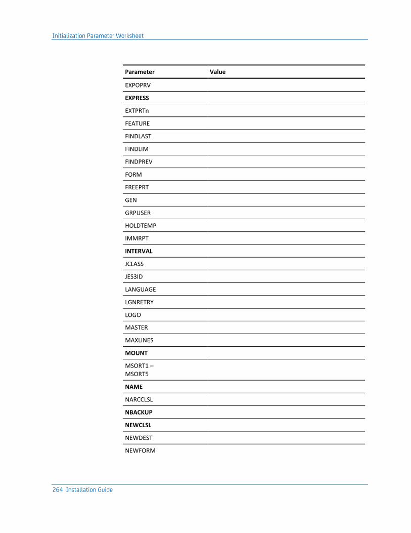
Initialization Parameter Worksheet
264 Installation Guide
Parameter Value
EXPOPRV
EXPRESS
EXTPRTn
FEATURE
FINDLAST
FINDLIM
FINDPREV
FORM
FREEPRT
GEN
GRPUSER
HOLDTEMP
IMMRPT
INTERVAL
JCLASS
JES3ID
LANGUAGE
LGNRETRY
LOGO
MASTER
MAXLINES
MOUNT
MSORT1 – MSORT5
NAME
NARCCLSL
NBACKUP
NEWCLSL
NEWDEST
NEWFORM

Initialization Parameter Worksheet
Appendix A: Installation Worksheets 265
Parameter Value
NEWPASS
NGEND
NGENI
NGENT
OUTLIM
PAGEMARK
PRTALL
PRTASA
PRTCLSL
RCVPRIM
RCVSEC
RCVSPACE
RCVUNIT
REDISP
RETPD
ROUT
ROUTBKP
SECID
SECLIST
SECURITY
SETPAGE
SMF
SMFTYPE
STACKBU
START
STORGRP0
STORGRX0
TAPECLSL
TAPEOPT
TAPESEQ

Expanded Retention Option (ERO) Initialization Parameters
266 Installation Guide
Parameter Value
TBACKUP
TIME
TPO54
TSOCLS
TSODEST
TSOFORM
TSOSCHED
UNITSPEC
UNLOAD
USERLIB
USERLVL
VPRTAPPL
VPRTMAXO
VPRTONL
VPRTPRINT
VPRTRTRY
WAIT
WRITER
XPRINT
Expanded Retention Option (ERO) Initialization Parameters
Parameter Value
DSK2DAYS
DSK2DRVR
DSK2INTV
DSK2MIGD
DSK2PARM
DSK2TIME
EROOPT

Archival Started Task Worksheet
Appendix A: Installation Worksheets 267
Parameter Value
EROPRO
PCOPIES
PMXTAPES
PMXYEARS
POPT
PRETAIN
PTEXT1 – PTEXT5
PTHRESH
PXCOND
STORGRP1-9
STORGRX1-9
Archival Started Task Worksheet
Use this worksheet to list the data set names used in various steps of the install process.
Accounting Data
DDname: SARACT
Data set name: _______________________________
Create Backup Report
DDname: SARBKLST
Data set name: _______________________________
Create Optical Migration Report
DDname: SARD2LST
Data set name: _______________________________

Archival Started Task Worksheet
268 Installation Guide
Tracking Backup Tapes (Highly Recommended)
DDname: SARRECV
Data set name: _______________________________
Exceptional Condition Checking Control Statements
DDname: SARXCTAB
Data set name: _______________________________
Expanded Retention Option (ERO) Control Statements
DDname: SARPATAB
Data set name: _______________________________

Appendix B: Integration with CA OPS/MVS EMA 269
Appendix B: Integration with CA OPS/MVS EMA
This section contains the following topics:
Overview (see page 269) Ensure that CA OPS/MVS Is Enabled for Capturing These Events (see page 270) CA View Active State Events (see page 270) CA View Heartbeat Events (see page 272)
Overview
CA View provides seamless integration with CA OPS/MVS by automatically communicating both active status events and heart beat events to CA OPS/MVS. The enabling technology for this is through a generic event API call that CA OPS/MVS provides the other mainframe products so that they can communicate events to CA OPS/MVS.
You do not need to do anything for CA View to enable this event communication interface to CA OPS/MVS. If CA View and CA OPS/MVS are active in the same z/OS image, CA View automatically communicates these automation events to CA OPS/MVS.
By generating active status events CA View and other CA products are able to communicate to CA OPS/MVS’s System State Manager (SSM) component when they are starting, up, stopping or down.
SSM is a built-in feature that uses an internal relational data framework to proactively monitor and manage started tasks, online applications, subsystems, JES initiators, and other z/OS resources including your CA mainframe products. SSM compares the current state of online systems, hardware devices, and the other resources with their desired state, and then automatically makes the necessary corrections when a resource is not in its desired state. This provides proactive and reactive state management of critical resources.

Ensure that CA OPS/MVS Is Enabled for Capturing These Events
270 Installation Guide
Before the CA OPS/MVS interface existed, CA OPS/MVS could automate active status events for your CA products; however this typically required monitoring unique messages for each CA product. With this interface, CA OPS/MVS can capture these events for any of your CA products with a single automation event rule.
With the heart beat event, CA View can communicate a normal, warning, or problem overall health status and reasoning to CA OPS/MVS on a regular interval. Once CA View begins generating heart beat events for CA OPS/MVS, CA OPS/MVS can also react to the lack of a heart beat event from CA View, treating this as an indication that there is either a potential problem with CA View, or there is a larger system-level problem that is taking place.
Ensure that CA OPS/MVS Is Enabled for Capturing These Events
To ensure that this CA OPS/MVS interface is active, make sure the CA OPS/MVS parameter APIACTIVE is set to its default of ON. This allows CA OPS/MVS to acknowledge and process the events generated by CA View and other CA products through this interface.
CA View Active State Events
CA View provides a direct interface to the CA OPS/MVS System State Manager (SSM) application to notify CA OPS/MVS of the current operating state of the given CA View address space. The CA OPS/MVS SSM application can use this information to automatically control the operation of the CA View address space, and any other address space that is dependent upon the CA View address space being active. For more information on using CA OPS/MVS SSM see the CA OPS/MVS User Guide.
The CA View product active state is presented to CA OPS/MVS and can be processed by the following rule:
)API CASTATE

CA View Active State Events
Appendix B: Integration with CA OPS/MVS EMA 271
The available OPS/REXX variables for CA View product state management are:
OPS/REXX Variable Value
API.APPLICATION CA View
API.VERSION Current release
API.LEVEL 00
API.EVENTID CASTATE
API.MSGID CASTATE
API.TEXT State of CA View
The API.TEXT variable has the following format:
State of appl_id is current_state'
appl_id
Specifies the same value as the API.APPLICATION variable
current_state
STARTING
Indicates that CA View is initializing
UP
Indicates that CA View is active
STOPPING
Indicates that CA View is terminating
DOWN
Indicates that CA View is exiting the system
For more information on how to use the CASTATE API, see the member SSMCAAPI of opsmvsHLQ.STATEMAN.RULES.

CA View Heartbeat Events
272 Installation Guide
CA View Heartbeat Events
CA View provides a continuous heartbeat event directly to CA OPS/MVS. CA OPS/MVS can use this information in several ways to determine the operational health of the CA View product.
CA View issues a heartbeat update every nnnn seconds that notifies CA OPS/MVS of the current operational health of the CA View product.
If CA View detects a health state change, it immediately generates a heartbeat update without waiting for the nnnn second heartbeat interval to expire. In this way, CA View provides CA OPS/MVS with a constant operational health state view of the CA View product.
CA OPS/MVS can also react to the lack of a heartbeat update from CA View and an indication that there is either a potential problem with CA View, or there is a larger system level problem that is taking place.
The CA View product heartbeat event is presented to CA OPS/MVS and can be processed by the following rule:
)API CAHEARTBT
The available OPS/REXX variables for CA View state management are:
OPS/REXX Variable Value
API.APPLICATION CA View
API.VERSION Current release
API.LEVEL 00
API.EVENTID CAHEARTBT
API.MSGID CAHEARTBT
API.TEXT State of CA View

CA View Heartbeat Events
Appendix B: Integration with CA OPS/MVS EMA 273
The API.TEXT variable has the following format:
appl_id Status: heartbeat_state Reason: reason_text
appl_id
Specifies the value of the API.APPLICATION variable.
heartbeat_state
Heart_beat_state can be one of the following:
NORMAL
Indicates that CA View is operating normally, without any detected problems.
WARNING
PROBLEM
reason_text
reason_text explains the problem as reported by the event API call.
For information on how you use the CAHEARTBT API, see members APIHRTB1, APIHRTB2, and APIHRTB3 of opsmvsHLQ.SAMPLE.RULES.


Index 275
Index
A
access login • 40
ACIF archiver proc, defining • 234, 244 ACIF interface, installing • 228, 238 adding variables • 103 allocate and mount • 47 archiver PROC, defining an • 256 ARCHMSG=YES|NO|LOG statement • 257 attributes • 103
highlight • 103 AUTOSTOP parameter • 251
B
backup tapes tracking • 107 BROWSE panel, customizing the • 103
C
CA GSS • 248 CA LMP • 23 CA MSM usage scenarios • 35 CA Roscoe • 144, 162
cross-memory online retrieval option, installing • 144
interface driver • 162 CA Spool interface option, installing • 228 CAI.SAMPJCL
library • 66 sample jobs • 66
CAIRIM • 23 Centera disk option • 22 CHARS,FORMDEF,PAGEDEF statement • 257 CICS • 150
menu system • 150 CLASS parameter • 252 color, defining for panels • 103 constants, modifying • 103 contacting technical support • 4 control statements, SARINIT • 262 copy files to USS directory • 50, 51, 54 cross-memory • 152, 161, 162, 171
drivers • 162 interface parameter requirements • 171 interfaces, installing • 161
services (XMS) • 152 alternate subsystem ID • 152 controlling subtask start-up options • 152 session timeout • 152
cryptographic hardware • 17 customer support, contacting • 4
D
defining • 229, 232, 234, 235, 239, 242, 244, 246 CA View FSA device control statements • 235,
246 JES2 initialization statements • 229, 239 JES3 initialization statements • 232, 242 the CA View ACIF archiver proc • 234, 244
deleting variables • 103 DEVICE statement parameters • 254
DTYPE • 254 FSSNAME • 254 HEADER = NO • 254 JNAME • 254 JUNIT • 254 MODE • 254 WS=() • 254
download files using ESD • 43 options • 50 overview • 41 to mainframe through a PC • 54 using batch JCL • 51
DRAIN|START DRAIN parameter • 252 drivers, cross-memory • 162 DTYPE parameter • 254
E
EMC Centera Disk Option • 22 ERO, installing • 225 external HOLDDATA • 62
F
FORMS parameter • 252 free space • 46 FSA device control statements, defining • 235, 246,
257 FSA startup, definition of • 249

276 Installation Guide
FSA, definition of • 249 FSS Collector • 257
defining • 257 FSA device control statements • 257
FSS, definition of • 249 FSSDEF statement (JES2) • 251
parameters • 251 AUTOSTOP • 251 FSSNAME • 251 HASPFSSM • 251 PROC • 251
FSSDEF statement (JES3) • 254 parameters • 254
FSSNAME • 254 PNAME • 254 SYSTEM • 254 TERM = YES|NO • 254 TYPE • 254
FSSNAME parameter • 251, 254
G
GIMUNZIP utility • 56 Global Subsystem interfaceSee CA GSS • 248 GSS interfaceSee CA GSS • 248
H
hardware requirements • 17 hash setting • 56 HASPFSSM parameter • 251 HEADER = NO parameter • 254 HELP panel • 102
choosing languages • 102 HELP panel, customizing the • 103 hexadecimal characters, reserved • 103 high-level qualifier • 56 highlight attributes • 103 HOLDDATA • 62
I
IEBCOPY • 66 IMS online retrieval option, installing • 155 IMS/DC access • 157 Initialization Parameter Worksheet • 262 installing • 91, 107, 131, 132, 139, 140, 144, 155,
161, 225, 226, 228, 238, 248, 249 ACIF interface • 228, 238 CA GSS interface • 248
CA Roscoe cross-memory online retrieval option • 144
CA Spool interface option • 228 cross-memory interfaces • 161 ERO • 225 from Pax-Enhanced ESD • 41 from tape • 65 FSS Collector • 249 Global Subsystem interfaceSee CA GSS • 248 IMS online retrieval option • 155 ISPF cross-memory online retrieval option • 132 online interfaces • 131 system extensions • 107 TSO cross-memory online retrieval option • 139 TSO online retrieval option • 91 VTAM online retrieval option • 140 VTAM print option • 226
Integrated Cryptographic Services Facility (ICSF) • 56 internal HOLDDATA • 62 ISPF • 132, 162
cross-memory online retrieval option, installing • 132
interface driver • 162
J
Java version support • 56 JES2 initialization statements • 229, 239, 251, 252
defining • 229, 239 FSSDEF statement • 251 PRINTER(nnnn) statement • 252
JES3 initialization statements • 232, 242, 254 defining • 232, 242 DEVICE statement • 254 FSSDEF statement • 254
JNAME parameter • 254 JUNIT parameter • 254
L
language • 97, 102 for HELP panels, setting • 102 for panels, setting • 97
length of variables • 103 LMP • 23, 86
key certificate • 86 overview • 23
LU names • 152 virtual • 152

Index 277
M
maintenance • 61 MODE parameter • 252, 254 modifying constants • 103 multi-session manager • 152
N
NAME statement • 257 NEWCLASS statement • 257 NEWDEST statement • 257 NEWFORM statement • 257 NEWPRMOD statement • 257 NEWWTR statement • 257 NOSEP parameter • 252
O
OLIB • 103 online • 131
interfaces, installing • 131
P
pax ESD procedure copy product files • 50 create product directory • 55 download files • 43 receive the SMP/E package • 57 set up USS directory • 46
pax file copy files to USS directory • 50, 51, 54
PNAME parameter • 254 position of variables • 103 PRINTER(nnnn) statement • 252
parameters • 252 CLASS • 252 DRAIN|START DRAIN • 252 FORMS • 252 FSS • 252 MODE • 252 NOSEP • 252 PRMODE • 252 ROUTECDE • 252 TRKCELL=YES • 252 WRITER • 252 WS • 252
PRMODE parameter • 252 PROC parameter • 251 process overview • 41
product download window • 43 product-level directory • 55 PRTnnnn DD statements • 256, 257
SARACT DD statement • 256 SARLOG DD statement • 256 SARXCTAB DD statement • 257
R
read me • 41, 56 ROUTECDE parameter • 252
S
sample JCL • 66 sample jobs • 51, 55
CAtoMainframe.txt • 51 Unpackage.txt • 55
SARACT DD statement • 256 SARINIT parameters • 249 SARINIT, running • 117 SARLOG DD statement • 256 SARXCTAB DD statement • 257 SMP/E
GIMUNZIP utility • 56 receive the package • 57
support, contacting • 4 system extensions, installing • 107 SYSTEM parameter • 254
T
tape, installing from • 65 technical support, contacting • 4 TERM = YES|NO parameter • 254 TRKCELL=YES parameter • 252 TSO • 91, 139, 162
cross-memory online retrieval option, installing • 139
interface driver • 162 online retrieval option, installing • 91
TYPE parameter • 254 TYPE=VIEW statement • 257
U
UNIX System Services (USS) access requirements • 41, 46 directory cleanup • 60 directory structure • 46
UNZIPJCL • 56

278 Installation Guide
V
variables • 103 adding • 103 deleting • 103 length of • 103 position of • 103
VIEW archiver PROC, defining • 256, 257 SARACT DD statement • 256 SARLOG DD statement • 256 SARXCTAB DD statement • 257
VTAM • 140, 226 online retrieval option, installing • 140 print option, installing • 226
W
worksheets • 262, 266, 267 Archival Started Task • 267 Expanded Retention Option • 266 Initialization Parameter • 262
WRITER parameter • 252 WS parameter • 252 WS=() parameter • 254
X
XMS (cross-memory services) • 152 alternate subsystem ID • 152 controlling subtask start-up options • 152 session timeout • 152