
C2045 E07 CU - Windstar Lines Safety Systems
870
MANUAL PARTS Introduction .......................................... 0 Complete vehicle ................................. 1 Traction engine .................................... 2 Suspension .......................................... 3 Driveline/Axle ....................................... 4 Brakes.................................................. 5 Transmission ....................................... 6 Steering................................................ 7 Climate control ..................................... 8 Occupant protection system ................ 9 Body and body accessories ............... 10 Control systems ................................. 11 Axles .................................................. 12 Compressed-air feed system............. 13 Electrical ............................................ 14 Indexes and lists ................................ 15 Bernard Van Hoolstraat 58 B-2500 Lier Koningshooikt BELGIUM Tel: +32-(0)3-420 20 20 - Fax: +32-(0)3-482 30 86 COACH C2045 E 07 CU CONSTRUCTION Nos. 46127 - 46178 SPECIFICATIONS MODEL VERSION "07" Engine: CUMMINS ISM07 Transmission: WT, ZF Drive Axle: DANA G171 Brakes: Knorr-Bremse SN7... Multiplex: V3 Publication No.: H0253en-US EDITION 2
-
Upload
khangminh22 -
Category
Documents
-
view
2 -
download
0
Transcript of C2045 E07 CU - Windstar Lines Safety Systems
MANUAL PARTS
Introduction .......................................... 0Complete vehicle ................................. 1Traction engine .................................... 2Suspension .......................................... 3Driveline/Axle....................................... 4Brakes.................................................. 5Transmission ....................................... 6Steering................................................ 7Climate control..................................... 8Occupant protection system ................ 9Body and body accessories............... 10Control systems................................. 11Axles .................................................. 12Compressed-air feed system............. 13Electrical ............................................ 14Indexes and lists ................................ 15
Bernard Van Hoolstraat 58B-2500 Lier Koningshooikt
BELGIUMTel: +32-(0)3-420 20 20 - Fax: +32-(0)3-482 30 86
COACHC2045 E07 CU
CONSTRUCTION Nos.46127 - 46178
SPECIFICATIONS MODEL VERSION "07"
Engine: CUMMINS ISM07Transmission: WT, ZFDrive Axle: DANA G171Brakes: Knorr-Bremse SN7...Multiplex: V3
Publication No.: H0253en-US
EDITION 2


Table of contents
Introduction The table of contents of the manual lists the manual parts and chapters. For subdivisions of a manual part or chapter, see the list on the “Overview” page at the beginning of that part or chapter.
How to handle updating material
Please note the identification marks which, in a revised table of contents, appear behind the date mark of a chapter:
+ : additional chapter; file into your manual according to the sequence shown in the contents table.
x : chapter modified since the previous edition of the contents list; insert as a replacement of the outdated one.
Contents This is edition 2
0 - Introduction
0.1 Preface 8 2 January 2008
1 - Complete vehicle
1.1 General 46 2 January 2008
2 - Traction engine
2.6 Engine suspension 4 2 January 2008
2.10 Fuel system 10 2 January 2008
2.22 Air intake system 12 2 January 2008
2.30 Exhaust system 14 2 January 2008
2.34 Cooling system 30 14 November 2008
2.38 Lubrication system 8 2 January 2008
2.46 Accessory drive systems 24 2 January 2008
3 - Suspension
3.6 Air suspension 18 2 January 2008
3.10 Front axle suspension 4 2 January 2008
3.14 Drive axle suspension 8 2 January 2008
3.18 Trailing axle suspension 4 2 January 2008
3.34 Wheels 10 2 January 2008
H0253en-US - Table of contents
2008-11-14 Maintenance manual
continued on next page.
i
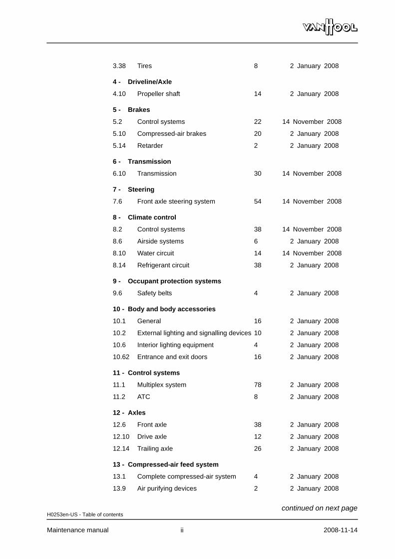
3.38 Tires 8 2 January 2008
4 - Driveline/Axle
4.10 Propeller shaft 14 2 January 2008
5 - Brakes
5.2 Control systems 22 14 November 2008
5.10 Compressed-air brakes 20 2 January 2008
5.14 Retarder 2 2 January 2008
6 - Transmission
6.10 Transmission 30 14 November 2008
7 - Steering
7.6 Front axle steering system 54 14 November 2008
8 - Climate control
8.2 Control systems 38 14 November 2008
8.6 Airside systems 6 2 January 2008
8.10 Water circuit 14 14 November 2008
8.14 Refrigerant circuit 38 2 January 2008
9 - Occupant protection systems
9.6 Safety belts 4 2 January 2008
10 - Body and body accessories
10.1 General 16 2 January 2008
10.2 External lighting and signalling devices 10 2 January 2008
10.6 Interior lighting equipment 4 2 January 2008
10.62 Entrance and exit doors 16 2 January 2008
11 - Control systems
11.1 Multiplex system 78 2 January 2008
11.2 ATC 8 2 January 2008
12 - Axles
12.6 Front axle 38 2 January 2008
12.10 Drive axle 12 2 January 2008
12.14 Trailing axle 26 2 January 2008
13 - Compressed-air feed system
13.1 Complete compressed-air system 4 2 January 2008
13.9 Air purifying devices 2 2 January 2008
H0253en-US - Table of contents
Maintenance manual 2008-11-14
continued on next page.
ii
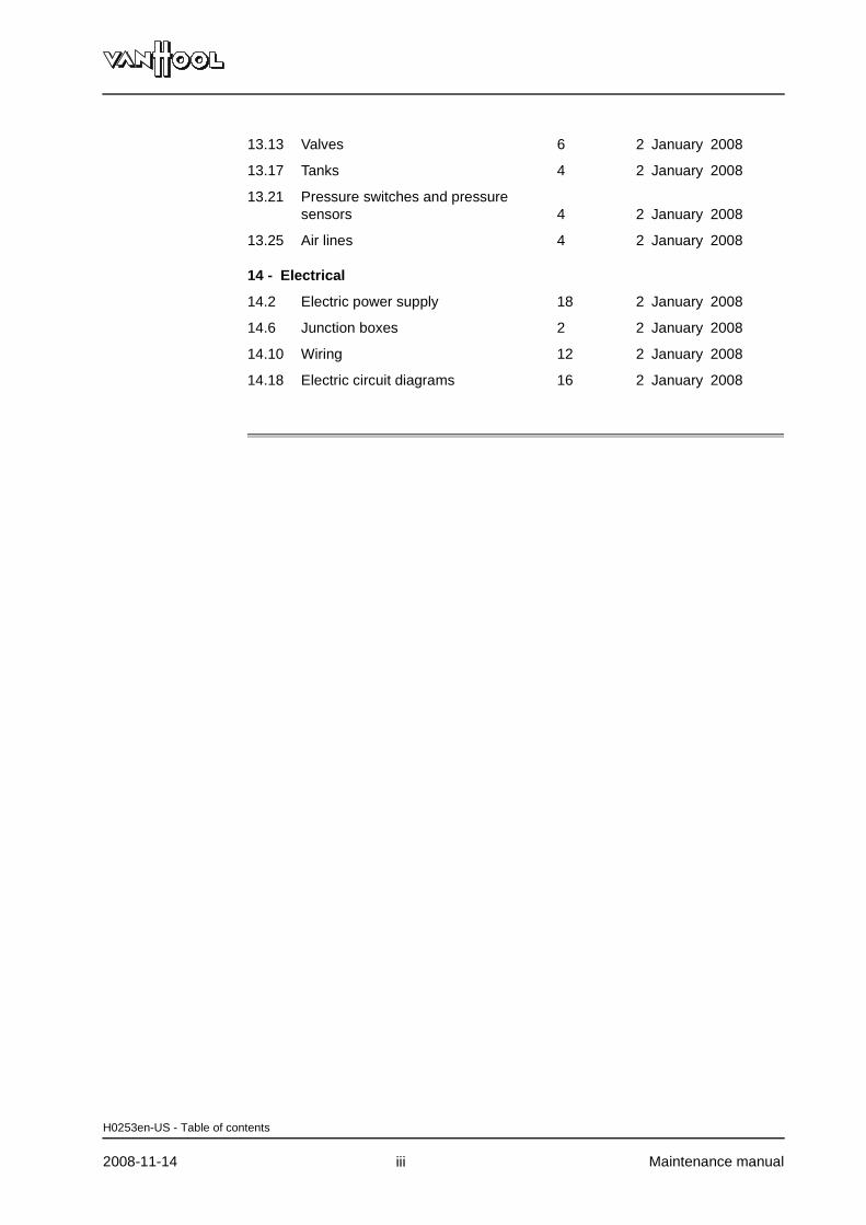
13.13 Valves 6 2 January 2008
13.17 Tanks 4 2 January 2008
13.21 Pressure switches and pressure sensors 4 2 January 2008
13.25 Air lines 4 2 January 2008
14 - Electrical
14.2 Electric power supply 18 2 January 2008
14.6 Junction boxes 2 2 January 2008
14.10 Wiring 12 2 January 2008
14.18 Electric circuit diagrams 16 2 January 2008
H0253en-US - Table of contents
2008-11-14 Maintenance manual
.
iii


Part 0 - Introduction
Overview
Contents
Chapter See page
Chapter 1: Preface 0.1-1

IntroductionPreface 0.1
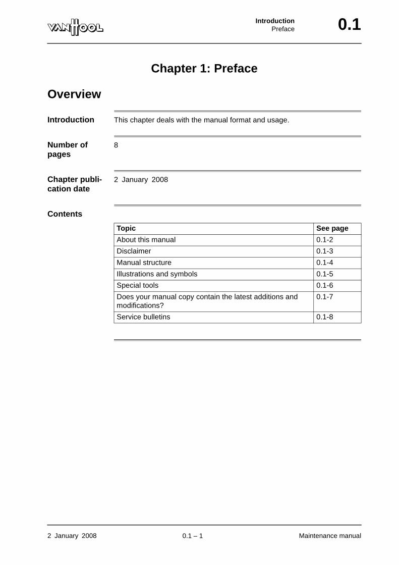
Chapter 1: Preface
Overview
Introduction This chapter deals with the manual format and usage.
Number of pages
8
Chapter publi-cation date
2 January 2008
Contents
Topic See page
About this manual 0.1-2
Disclaimer 0.1-3
Manual structure 0.1-4
Illustrations and symbols 0.1-5
Special tools 0.1-6
Does your manual copy contain the latest additions and modifications?
0.1-7
Service bulletins 0.1-8
2 January 2008 Maintenance manual
.
0.1 – 1
0.1 IntroductionPreface
About this manual
What does this manual deal with?
This manual deals with information regarding the operation and the mainte-nance of the vehicle model mentioned on the title page. It also contains important safety instructions, technical data, component specifications and general troubleshooting instructions.
Other infor-mation
Activities that are not described in this manual, such as repair of drive line components and extensive tests of electronic units, are dealt with in the workshop instructions by Van Hool's suppliers. At request Van Hool acts as an intermediary to supply these publications.
There is also an operating manual available for the vehicle (publication number: replace the initial letter "H" of the maintenance manual publication number by a "B")
Who does this manual address?
The manual addresses experienced garage personnel which is familiar with the maintenance of heavy commercial vehicles and the general safety rules involved.
Read, before you begin
Everyone whose task it is to carry out work on the vehicle has to read the pages of this manual applicable to his job, before starting any activity. This applies in particular to the pages containing safety instructions at the beginning of chapter 1.1 and to all safety instructions contained in the text of other chapters.
Follow instruc-tions
Carefully following the instructions in this manual is the prerequisite for traffic safety and operational reliability of your vehicle. Non-compliance with the instructions causes all warranty claims to expire.
How to order further copies?
Copies can be ordered from your Van Hool representative or directly from the Van Hool After Sales Department at Koningshooikt-Lier. Please mention the publication number of the manual as well as the number of copies required. The publication number is to be found in the bottom righthand corner of the title page. If the vehicle is built to the customer's own specifications, its con-struction number also appears on the title page. In this case, also mention that number when ordering.
000679 en-US
Maintenance manual 2 January 2008
.
0.1 – 2
IntroductionPreface 0.1
Disclaimer
Differences from the product described
The data and illustrations in this manual are based upon the newest product information available at the time of printing. Van Hool reserves the right to make changes to its product without prior notice.
Inaccuracies or short-comings
Great care has been observed in writing this manual. In spite of this fact, the Van Hool company does not accept any liability for damage or discomfort in any sense that could be attributed to errors or shortcomings contained in this manual.
Instruction not mentioned
Failure to mention maintenance instructions in this manual for certain comfort features does not automatically mean that said features require no mainte-nance. To the extent possible, separate documentation is supplied sepa-rately with the documents supplied with the vehicle.
Improper use of the vehicle
Van Hool is not liable for damage or accidents occurring as a result of improper use of the vehicle. This involves: operation under circumstances or for a purpose improper to the vehicle concept, or a driving style abnormal to bus or coach operation.
Spare parts The use of accessories and spare parts not issued by Van Hool or which are not original Van Hool parts will result in the loss of all guarantee claims.
000680 en-US
2 January 2008 Maintenance manual
.
0.1 – 3
0.1 IntroductionPreface
Manual structure
What is the structure based on?
The manual structure is based on the structure of the vehicle in terms of com-ponents and systems.
Parts There are 16 parts (0 through 15). They are easily traceable by means of the blue cardboard divider sheets.
Chapters Each manual part has been divided into chapters. The chapters are in numeric order within the manual part they come under. However, the numbers do not necessarily link up. Some numbers may be lacking in the sequence. However, this does not mean that your manual is incomplete. The reason is that your vehicle contains only part of the components the Van Hool numbering system reserves entries for.
Pages Page numbering is restarted at the beginning of each chapter. All pages within a same chapter bear the same date: the chapter publication date.
Table of contents
Completely at the front, you will find the manual's table of contents. It lists all the parts and chapters present in the manual.
Overview pages
Each part and each chapter begins with an overview page.
Addenda Behind the blue cardboard divider sheet "Addenda", you may come across documents that, for their different type of layout or page numbering, could not be fitted into the overall structure of the manual. These are mostly instruction sheets from Van Hool suppliers, presented in their original format.
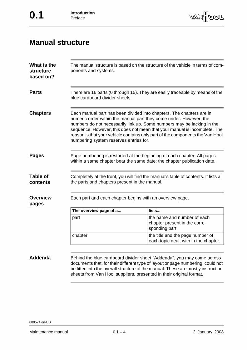
The overview page of a... lists...
part the name and number of each chapter present in the corre-sponding part.
chapter the title and the page number of each topic dealt with in the chapter.
000574 en-US
Maintenance manual 2 January 2008
.
0.1 – 4
IntroductionPreface 0.1
Illustrations and symbols
Applicability of the illustra-tions
Some of the illustrations in this manual are simplified or common. They will not look exactly like the component or equipment found on your vehicle. However, the procedures they illustrate do apply to your vehicle.
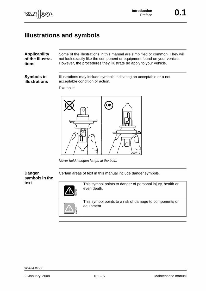
Symbols in illustrations
Illustrations may include symbols indicating an acceptable or a not acceptable condition or action.
Example:
Never hold halogen lamps at the bulb.
Danger symbols in the text
Certain areas of text in this manual include danger symbols.
This symbol points to danger of personal injury, health or even death.
This symbol points to a risk of damage to components or equipment.
000683 en-US
2 January 2008 Maintenance manual
.
0.1 – 5
0.1 IntroductionPreface
Special tools
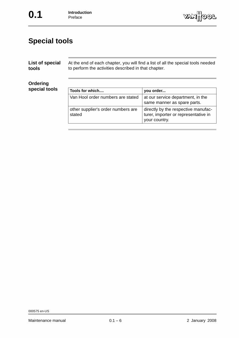
List of special tools
At the end of each chapter, you will find a list of all the special tools needed to perform the activities described in that chapter.
Ordering special tools Tools for which.... you order...
Van Hool order numbers are stated at our service department, in the same manner as spare parts.
other supplier's order numbers are stated
directly by the respective manufac-turer, importer or representative in your country.
000575 en-US
Maintenance manual 2 January 2008
.
0.1 – 6

IntroductionPreface 0.1
Does your manual copy contain the latest additions and modifications?
To check the status of your copy
Use the table of contents at the beginning of the manual.
Is your copy complete?
Your manual is complete when all the chapters listed in the table of contents are actually present and contain the number of pages stated behind the chapter title in the table of contents.
Is your copy up-to-date?
An edition number on the first page of the manual's table of contents indicates to which edition of your manual the table of contents belongs. In order to know whether a chapter has been updated to the level of that particular edition, compare the date mark in the chapter itself with the date given behind the chapter title in the table of contents.
Method of updating
All manual holders registered in our mailing list automatically receive the additions and modifications deemed necessary by Van Hool.
Updates are always supplied as complete chapters. You will recognise a modified chapter by its more recent date mark.
What does an updating package consist of?
An updating package consists of additional/replacement chapters, plus a new table of contents for the manual.
003599 en-US
2 January 2008 Maintenance manual
.
0.1 – 7
0.1 IntroductionPreface
Service bulletins
Introduction As an additional means of informing you on technical items, Van Hool from time to time sends you service bulletins.
How to treat service bulletins?
File service bulletins related to a subject treated in this manual in numerical order behind the blue cardboard divider sheet with the title "Service bulletins". Manually mark the page(s) involved with the service bulletin number. Thus you will be remembered of the bulletin you filed when you leaf throught the manual.
Priority The information passed on in service bulletins always takes priority over information that deviates from and is older than the service bulletin.
003598 en-US
Maintenance manual 2 January 2008
.
0.1 – 8

Part 1 - Complete vehicle
Overview
Contents
Chapter See page
Chapter 1: General 1.1-1

Complete vehicleGeneral 1.1
Chapter 1: General
Overview
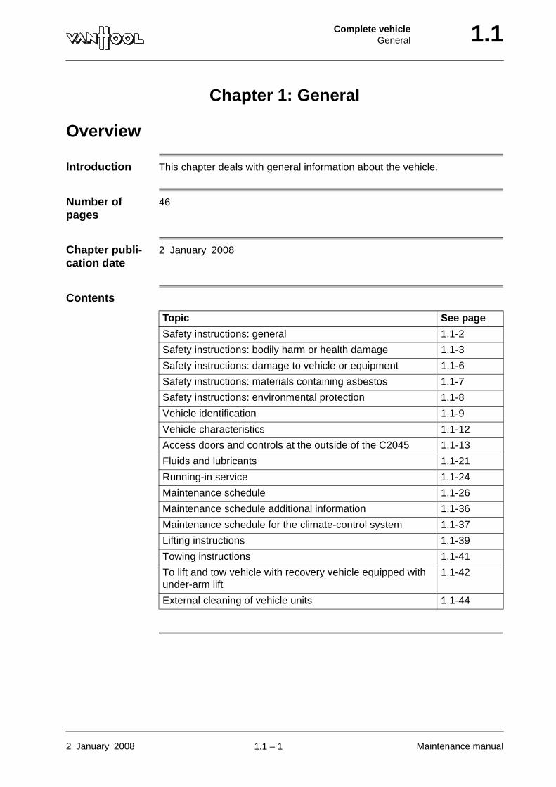
Introduction This chapter deals with general information about the vehicle.
Number of pages
46
Chapter publi-cation date
2 January 2008
Contents
Topic See page
Safety instructions: general 1.1-2
Safety instructions: bodily harm or health damage 1.1-3
Safety instructions: damage to vehicle or equipment 1.1-6
Safety instructions: materials containing asbestos 1.1-7
Safety instructions: environmental protection 1.1-8
Vehicle identification 1.1-9
Vehicle characteristics 1.1-12
Access doors and controls at the outside of the C2045 1.1-13
Fluids and lubricants 1.1-21
Running-in service 1.1-24
Maintenance schedule 1.1-26
Maintenance schedule additional information 1.1-36
Maintenance schedule for the climate-control system 1.1-37
Lifting instructions 1.1-39
Towing instructions 1.1-41
To lift and tow vehicle with recovery vehicle equipped with under-arm lift
1.1-42
External cleaning of vehicle units 1.1-44
2 January 2008 Maintenance manual
.
1.1 – 1
1.1 Complete vehicleGeneral
Safety instructions: general
Prevention of accidents and damage
To help prevent accidents and damage, a series of general customary safety rules for dealing with commercial vehicles is provided below. Special warnings have also been provided in various chapters of this manual, referring to work instructions to which they apply.
Read all these rules and warnings attentively, in both your own safety interest and that of the vehicle.
Competent staff
Using the vehicle described in this manual is safe on the condition that the personnel responsible for its operation and maintenance are adequately trained and follow the necessary precautions.
Responsibility Inclusion of these safety rules does not mean that Van Hool is responsible for the compliance with them in your company. It must also be emphasized that Van Hool cannot possibly anticipate ALL situations or improper actions that could lead to an accident, damage or health problems.
000687 en-US
Maintenance manual 2 January 2008
.
1.1 – 2

Complete vehicleGeneral 1.1
Safety instructions: bodily harm or health damage
Introduction Below you will find rules to prevent accidents causing bodily harm or health damage.
Before operation
Familiarize yourself with the location and the function of all controls, before you drive the vehicle for the first time.
To start the engine
Always make sure the parking brake has been applied and the transmission is in neutral, before starting the engine.
Exhaust emissions
Do not run the engine or operate the coolant heater in a confined space, unless a proper exhaust removing system is used.
Refueling Due to fire risk refueling is allowed with the engine and the heating system switched off only (coolant heater!).
Working on the vehicle
• Make sure you have read and understood all applicable instructions before beginning any work.
• Before working on parts in the engine compartment, activate the starter-prevention switch (if present) to prevent anyone from turning on the engine. Put a warning on the steering wheel saying "DO NOT START: MAINTENANCE".
• As a rule, maintenance has to be performed, while the engine is not running. If you have to conduct checks, while the engine is running, keep distance from the moving parts (Caution: optical illusion may cause a running fan to look like it is not turning).
• Beware that the vehicle superstructure can suddenly drop over 3 in, if someone (intentionally or unintentionally) allows air to escape from the suspension air springs.
• Firmly support all heavy vehicle parts, before you unscrew fixing bolts or nuts.
• Except when adjusting tire pressure, always fill tires in a safety cage.
Tools • For a number of activities the use of special tools is prescribed. If you use different tools in those cases, you do so at your own risk.
• Never use any tools without having learnt how to handle them first.
• Use tools in proper condition only. Worn-out nut wrenches, for example, can slip away dangerously and cause injury.
003841 en-US
2 January 2008 Maintenance manual
continued on next page.
1.1 – 3
1.1 Complete vehicleGeneral
Risks of burns • Do not touch with bare hands an engine, transmission or retarder that has been operating recently: danger of burns.
• Beware of burns, when draining hot oil. Do not touch oil drain plugs and filters with bare hands. Make sure the catcher tray you place under the drain plug is big enough, so that it will not overflow (refer to chapter 1.1, "Fluids and lubricants").
• Never open the engine cooling or interior heating system, while the coolant is hot. If this is necessary due to some obligatory reason, however, first release the pressure from the system as outlined in chapter 2.34.
Systems under pressure
• Do not tighten or loosen pipe or hose connections, while the pipe or hose is under pressure (fuel lines, lubricating oil, hydraulic fluid, compressed air, etc.).
• Do not check pressurized lines for leaks with your hands.
• Safely depressurize devices containing compressed air or liquid under pressure, before opening them.
• Gas struts of body hatches contain gas under dangerously high pressure. Never drill through these struts or open them.
Batteries • When disconnecting or connecting batteries, always disconnect the neg-ative cable first and reconnect it last (so as to avoid short circuits).
• Batteries contain highly corrosive acid; battery gas is explosive (refer to chapter 14.2 "Safety instructions relating to batteries").
Jacking • Before jacking up the vehicle, make sure the brakes have been applied and the wheels remaining on the ground have been secured with wheel chocks.
• Use faultless and suitable jack types only, with sufficient lifting power.
• Never support the vehicle with hydraulic jacks only; always place chassis stands or support blocks, before working under a jacked-up vehicle.
Hazardous substances
• Beware of explosion danger, when draining fuel tanks.
• Avoid any contact with the skin and eyes with corrosive substances or irri-tants. Wear protective clothing, gloves, safety goggles.
• Avoid ingestion or inhalation and skin contact with toxic substances. Wear protective clothing and, if necessary, a suitable respiration mask.
• If victims are injured in an accident with corrosive or toxic substances, call for a doctor immediately.
003841 en-US
Maintenance manual 2 January 2008
continued on next page.
1.1 – 4
Complete vehicleGeneral 1.1
• Never keep vehicle liquids in packings that could be confused with bev-erage packings.
• Make sure the workshop has "safety data sheets" at hand for all haz-ardous substances used. These sheets indicate the substance properties, precautionary measures in dealing with it and recommendations for first aid in the event of an accident. They are available from the supplier of the hazardous substance.
• When working with parts containing asbestos, carefully follow the instruc-tions stated under "Safety instructions: materials containing asbestos" later in this chapter.
003841 en-US
2 January 2008 Maintenance manual
.
1.1 – 5

1.1 Complete vehicleGeneral
Safety instructions: damage to vehicle or equipment
Introduction Below you will find rules to prevent damage to the vehicle or equipment.
Defects Make sure every defect that is identified is fixed as soon as possible to prevent greater damage.
Screws and nuts
• Screws and nuts may be replaced with those having the same part number (or equivalent) only, never use screws or nuts of a lower property class.
• Observe the tightening torques specified in the various chapters of this manual, when tightening screws and nuts.
Electrical system
• Turn off the battery isolating switch, before working on the electrical system of the vehicle.
• When the battery isolating switch is closed, never pull out the connectors of any electronic control unit (automatic transmission, ABS/ATC, E-GAS, EDC, speed-limiting device, cruise control, etc.).
Electric welding
Before carrying out electrical welding on the vehicle, first turn off the battery isolating switch and subsequently remove the connectors from all electronic control units. Secure the ground return cable of the welding device as close as possible to the part that is to be welded.
Engine encap-sulation
When working on vehicles with engine encapsulation, make sure to check afterwards that no flammable substances are left on the bottom of the engine encapsulation (e.g. diesel fuel after bleeding the fuel system).
Jacking Jack up the chassis frame under the jack support points provided for this purpose only. These points have been indicated in chapter 1.1, under "Lifting instructions".
Overheated engine
Never pour cold coolant into an overheated engine.
000689 en-US
Maintenance manual 2 January 2008
.
1.1 – 6
Complete vehicleGeneral 1.1
Safety instructions: materials containing asbestos
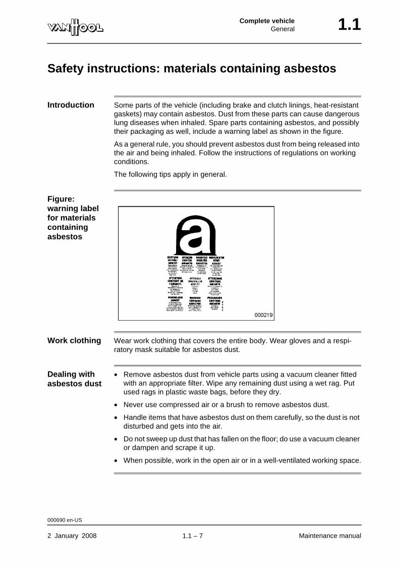
Introduction Some parts of the vehicle (including brake and clutch linings, heat-resistant gaskets) may contain asbestos. Dust from these parts can cause dangerous lung diseases when inhaled. Spare parts containing asbestos, and possibly their packaging as well, include a warning label as shown in the figure.
As a general rule, you should prevent asbestos dust from being released into the air and being inhaled. Follow the instructions of regulations on working conditions.
The following tips apply in general.
Figure: warning label for materials containing asbestos
Work clothing Wear work clothing that covers the entire body. Wear gloves and a respi-ratory mask suitable for asbestos dust.
Dealing with asbestos dust
• Remove asbestos dust from vehicle parts using a vacuum cleaner fitted with an appropriate filter. Wipe any remaining dust using a wet rag. Put used rags in plastic waste bags, before they dry.
• Never use compressed air or a brush to remove asbestos dust.
• Handle items that have asbestos dust on them carefully, so the dust is not disturbed and gets into the air.
• Do not sweep up dust that has fallen on the floor; do use a vacuum cleaner or dampen and scrape it up.
• When possible, work in the open air or in a well-ventilated working space.
000690 en-US
2 January 2008 Maintenance manual
.
1.1 – 7
1.1 Complete vehicleGeneral
Safety instructions: environmental protection
Introduction Below you will find rules to prevent damage to environment we live in.
Toxins or pollutants
Do not dump any toxins or pollutants into the environment. Lubricants, anti-freeze, liquids for hydraulic systems, battery acid, batteries, fuel and oil filters, asbestos are "special waste" and may only be disposed of in a manner per-mitted by law. Check with the environmental protection authorities to find out applicable regulations in your country (or region).
Exhaust gas Do not unnecessarily idle the vehicle engine. Exhaust emissions cause envi-ronmental pollution.
000691 en-US
Maintenance manual 2 January 2008
.
1.1 – 8

Complete vehicleGeneral 1.1
Vehicle identification
Vehicle identi-fication plate
Figure: vehicle identification plate
A 1st axleB 2nd axleC 3rd axleD Gross vehicle weight ratingE Manufacturing dateF Gross axle weight ratingG Tire sizeH Rim sizeI Tire inflation pressure (cold tires)J Production numberK Chassis number
The vehicle identification plate is located in the step well of the vehicle.
007123 en-US
2 January 2008 Maintenance manual
continued on next page.
1.1 – 9
1.1 Complete vehicleGeneral
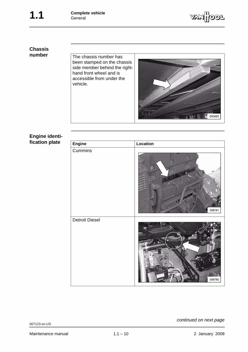
Chassis number
Engine identi-fication plate
The chassis number has been stamped on the chassis side member behind the right-hand front wheel and is accessible from under the vehicle.
Engine Location
Cummins
Detroit Diesel
007123 en-US
Maintenance manual 2 January 2008
continued on next page.
1.1 – 10
Complete vehicleGeneral 1.1
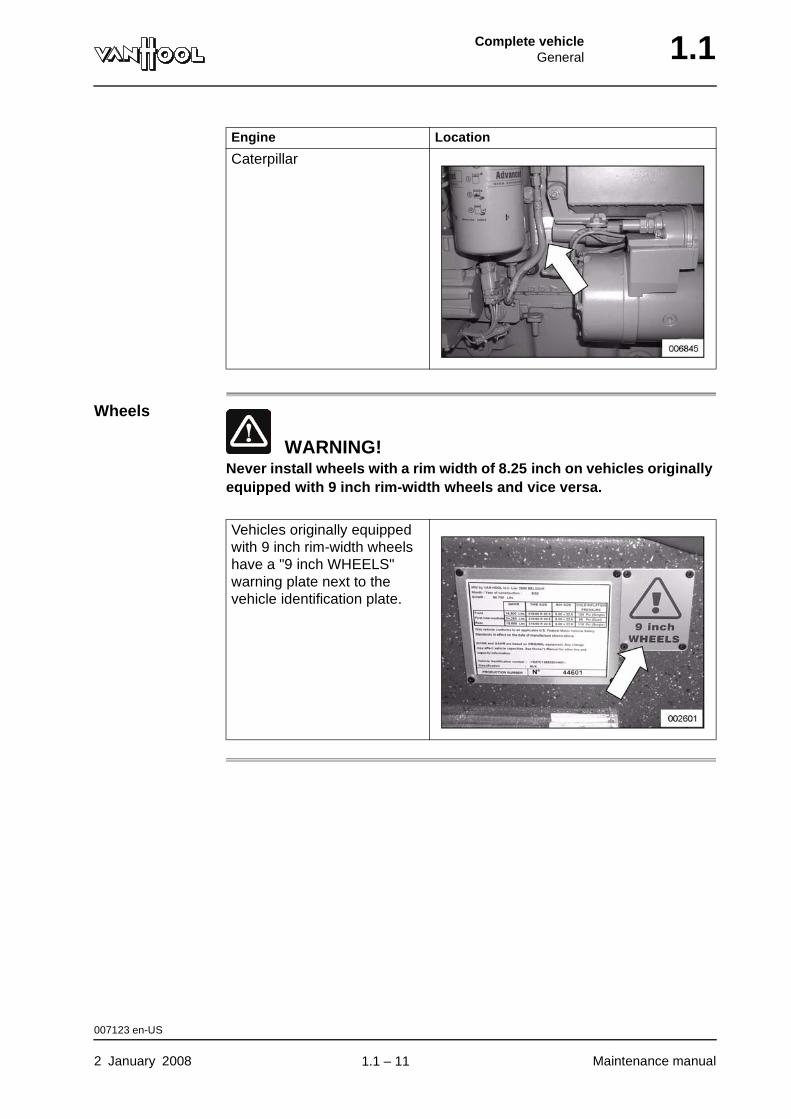
Wheels
WARNING!Never install wheels with a rim width of 8.25 inch on vehicles originally equipped with 9 inch rim-width wheels and vice versa.
Caterpillar
Engine Location
Vehicles originally equipped with 9 inch rim-width wheels have a "9 inch WHEELS" warning plate next to the vehicle identification plate.
007123 en-US
2 January 2008 Maintenance manual
.
1.1 – 11
1.1 Complete vehicleGeneral
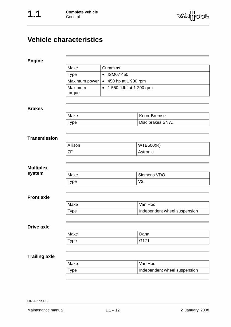
Vehicle characteristics
Engine
Brakes
Transmission
Multiplex system
Front axle
Drive axle
Trailing axle
Make Cummins
Type • ISM07 450
Maximum power • 450 hp at 1 900 rpm
Maximum torque
• 1 550 ft.lbf at 1 200 rpm
Make Knorr-Bremse
Type Disc brakes SN7...
Allison WTB500(R)
ZF Astronic
Make Siemens VDO
Type V3
Make Van Hool
Type Independent wheel suspension
Make Dana
Type G171
Make Van Hool
Type Independent wheel suspension
007267 en-US
Maintenance manual 2 January 2008
.
1.1 – 12
Complete vehicleGeneral 1.1
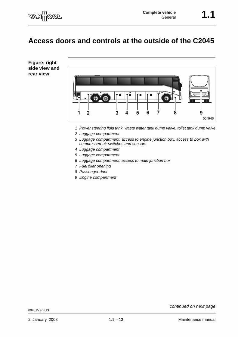
Access doors and controls at the outside of the C2045
Figure: right side view and rear view
1 Power steering fluid tank, waste water tank dump valve, toilet tank dump valve2 Luggage compartment3 Luggage compartment, access to engine junction box, access to box with
compressed-air switches and sensors4 Luggage compartment5 Luggage compartment6 Luggage compartment, access to main junction box7 Fuel filler opening8 Passenger door9 Engine compartment
004815 en-US
2 January 2008 Maintenance manual
continued on next page.
1.1 – 13

1.1 Complete vehicleGeneral
Figure: left side view and front view
1 Roof hatch2 Spare wheel, compressed-air system fill connection3 Coolant filler cap4 Air filter, air-filter service indicator, batteries, mechanical battery isolating
switch, access to battery junction box5 Coolant heater, main shut-off valve in interior heating supply line, main shut-
off valve in interior heating return line, interior heating valve block6 Climate-control condensor compartment7 Luggage compartment8 Luggage compartment9 Luggage compartment
10 Windshield washer tank, front-bumper release lever
In engine com-partment Element Location
Coolant sight glass
004815 en-US
Maintenance manual 2 January 2008
continued on next page.
1.1 – 14
Complete vehicleGeneral 1.1
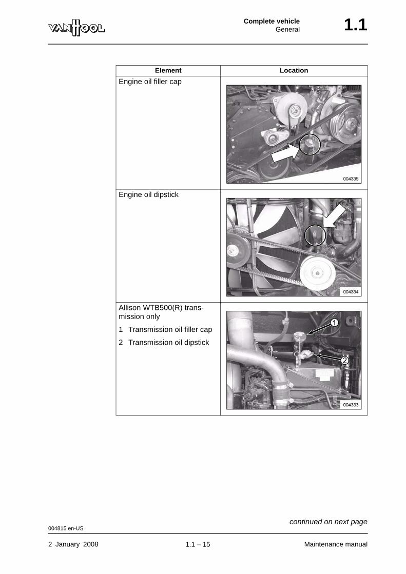
Engine oil filler cap
Engine oil dipstick
Allison WTB500(R) trans-mission only
1 Transmission oil filler cap
2 Transmission oil dipstick
Element Location
004815 en-US
2 January 2008 Maintenance manual
continued on next page.
1.1 – 15
1.1 Complete vehicleGeneral
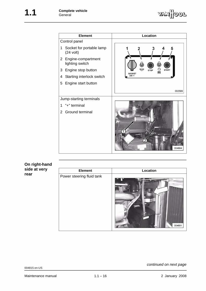
On right-hand side at very rear
Control panel
1 Socket for portable lamp (24 volt)
2 Engine-compartment lighting switch
3 Engine stop button
4 Starting interlock switch
5 Engine start button
Jump-starting terminals
1 "+" terminal
2 Ground terminal
Element Location
Element Location
Power steering fluid tank
004815 en-US
Maintenance manual 2 January 2008
continued on next page.
1.1 – 16
Complete vehicleGeneral 1.1
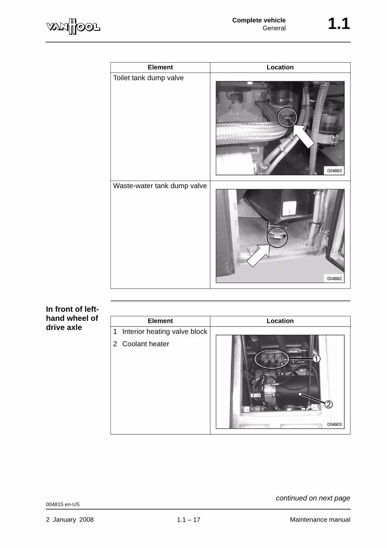
In front of left-hand wheel of drive axle
Toilet tank dump valve
Waste-water tank dump valve
Element Location
Element Location
1 Interior heating valve block
2 Coolant heater
004815 en-US
2 January 2008 Maintenance manual
continued on next page.
1.1 – 17
1.1 Complete vehicleGeneral
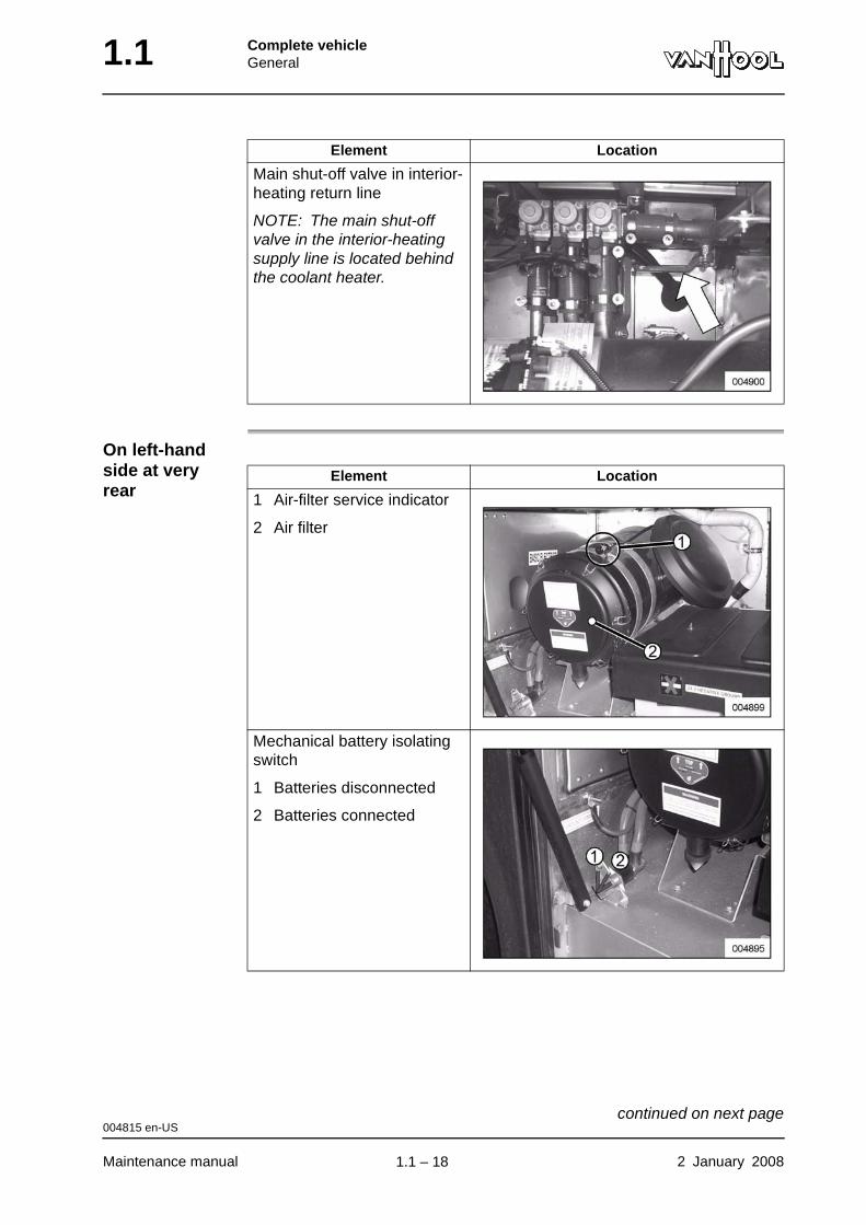
On left-hand side at very rear
Main shut-off valve in interior-heating return line
NOTE: The main shut-off valve in the interior-heating supply line is located behind the coolant heater.
Element Location
Element Location
1 Air-filter service indicator
2 Air filter
Mechanical battery isolating switch
1 Batteries disconnected
2 Batteries connected
004815 en-US
Maintenance manual 2 January 2008
continued on next page.
1.1 – 18
Complete vehicleGeneral 1.1
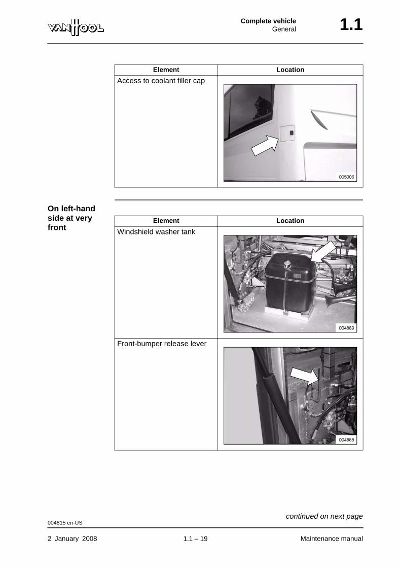
On left-hand side at very front
Access to coolant filler cap
Element Location
Element Location
Windshield washer tank
Front-bumper release lever
004815 en-US
2 January 2008 Maintenance manual
continued on next page.
1.1 – 19
1.1 Complete vehicleGeneral
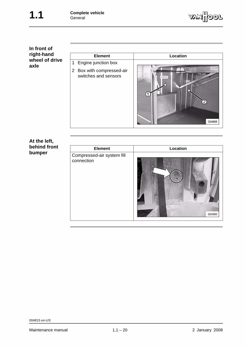
In front of right-hand wheel of drive axle
At the left, behind front bumper
Element Location
1 Engine junction box
2 Box with compressed-air switches and sensors
Element Location
Compressed-air system fill connection
004815 en-US
Maintenance manual 2 January 2008
.
1.1 – 20
Complete vehicleGeneral 1.1
Fluids and lubricants
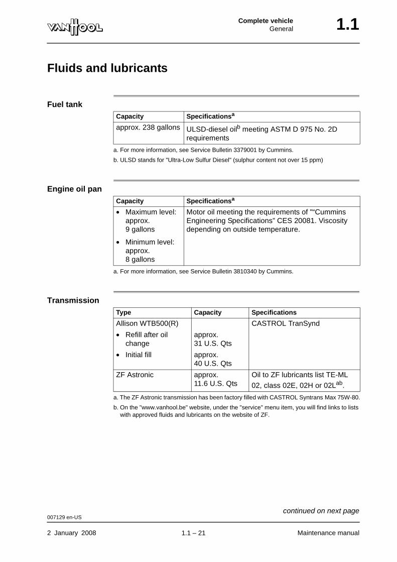
Fuel tank
Engine oil pan
Transmission
Capacity Specificationsa
a. For more information, see Service Bulletin 3379001 by Cummins.
approx. 238 gallons ULSD-diesel oilb meeting ASTM D 975 No. 2D requirements
b. ULSD stands for "Ultra-Low Sulfur Diesel" (sulphur content not over 15 ppm)
Capacity Specificationsa
a. For more information, see Service Bulletin 3810340 by Cummins.
• Maximum level: approx. 9 gallons
• Minimum level: approx. 8 gallons
Motor oil meeting the requirements of "“Cummins Engineering Specifications” CES 20081. Viscosity depending on outside temperature.
Type Capacity Specifications
Allison WTB500(R) CASTROL TranSynd
• Refill after oil change
approx. 31 U.S. Qts
• Initial fill approx. 40 U.S. Qts
ZF Astronic approx. 11.6 U.S. Qts
Oil to ZF lubricants list TE-ML
02, class 02E, 02H or 02Lab.
a. The ZF Astronic transmission has been factory filled with CASTROL Syntrans Max 75W-80.
b. On the "www.vanhool.be" website, under the "service" menu item, you will find links to lists with approved fluids and lubricants on the website of ZF.
007129 en-US
2 January 2008 Maintenance manual
continued on next page.
1.1 – 21
1.1 Complete vehicleGeneral
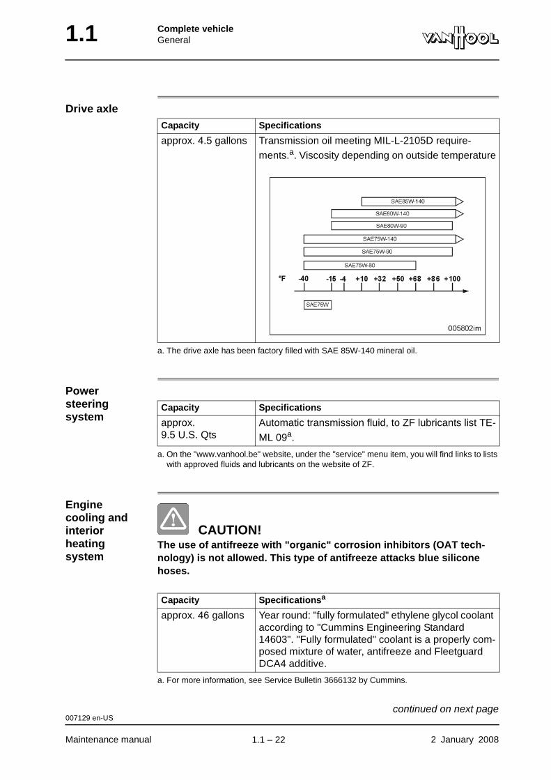
Drive axle
Power steering system
Engine cooling and interior heating system
CAUTION!The use of antifreeze with "organic" corrosion inhibitors (OAT tech-nology) is not allowed. This type of antifreeze attacks blue silicone hoses.
Capacity Specifications
approx. 4.5 gallons Transmission oil meeting MIL-L-2105D require-
ments.a. Viscosity depending on outside temperature
a. The drive axle has been factory filled with SAE 85W-140 mineral oil.
Capacity Specifications
approx. 9.5 U.S. Qts
Automatic transmission fluid, to ZF lubricants list TE-
ML 09a.
a. On the "www.vanhool.be" website, under the "service" menu item, you will find links to lists with approved fluids and lubricants on the website of ZF.
Capacity Specificationsa
a. For more information, see Service Bulletin 3666132 by Cummins.
approx. 46 gallons Year round: "fully formulated" ethylene glycol coolant according to "Cummins Engineering Standard 14603". "Fully formulated" coolant is a properly com-posed mixture of water, antifreeze and Fleetguard DCA4 additive.
007129 en-US
Maintenance manual 2 January 2008
continued on next page.
1.1 – 22
Complete vehicleGeneral 1.1
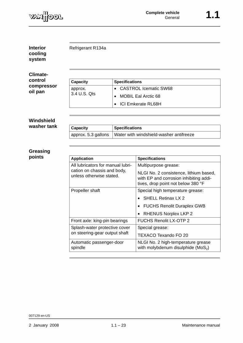
Interior cooling system
Refrigerant R134a
Climate-control compressor oil pan
Windshield washer tank
Greasing points
Capacity Specifications
approx. 3.4 U.S. Qts
• CASTROL Icematic SW68
• MOBIL Eal Arctic 68
• ICI Emkerate RL68H
Capacity Specifications
approx. 5.3 gallons Water with windshield-washer antifreeze
Application Specifications
All lubricators for manual lubri-cation on chassis and body, unless otherwise stated.
Multipurpose grease:
NLGI No. 2 consistence, lithium based, with EP and corrosion inhibiting addi-tives, drop point not below 380 °F
Propeller shaft Special high temperature grease:
• SHELL Retinax LX 2
• FUCHS Renolit Duraplex GWB
• RHENUS Norplex LKP 2
Front axle: king-pin bearings FUCHS Renolit LX-OTP 2
Splash-water protective cover on steering-gear output shaft
Special grease:
TEXACO Texando FO 20
Automatic passenger-door spindle
NLGI No. 2 high-temperature grease with molybdenum disulphide (MoS2)
007129 en-US
2 January 2008 Maintenance manual
.
1.1 – 23
1.1 Complete vehicleGeneral
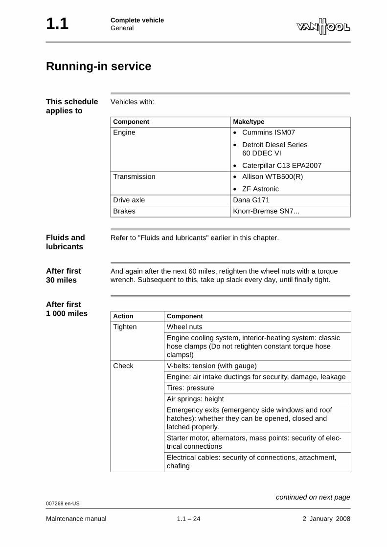
Running-in service
This schedule applies to
Vehicles with:
Fluids and lubricants
Refer to "Fluids and lubricants" earlier in this chapter.
After first 30 miles
And again after the next 60 miles, retighten the wheel nuts with a torque wrench. Subsequent to this, take up slack every day, until finally tight.
After first 1 000 miles
Component Make/type
Engine • Cummins ISM07
• Detroit Diesel Series 60 DDEC VI
• Caterpillar C13 EPA2007
Transmission • Allison WTB500(R)
• ZF Astronic
Drive axle Dana G171
Brakes Knorr-Bremse SN7...
Action Component
Tighten Wheel nuts
Engine cooling system, interior-heating system: classic hose clamps (Do not retighten constant torque hose clamps!)
Check V-belts: tension (with gauge)
Engine: air intake ductings for security, damage, leakage
Tires: pressure
Air springs: height
Emergency exits (emergency side windows and roof hatches): whether they can be opened, closed and latched properly.
Starter motor, alternators, mass points: security of elec-trical connections
Electrical cables: security of connections, attachment, chafing
007268 en-US
Maintenance manual 2 January 2008
continued on next page.
1.1 – 24
Complete vehicleGeneral 1.1
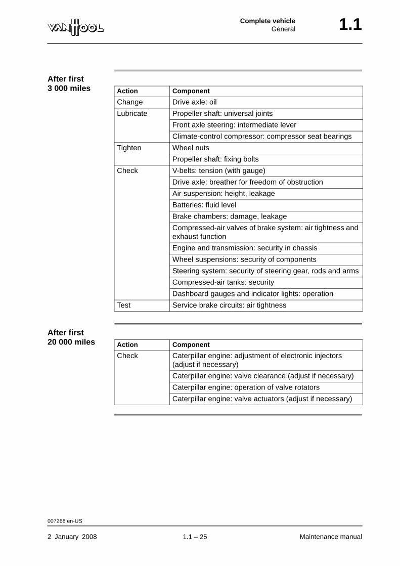
After first 3 000 miles
After first 20 000 miles
Action Component
Change Drive axle: oil
Lubricate Propeller shaft: universal joints
Front axle steering: intermediate lever
Climate-control compressor: compressor seat bearings
Tighten Wheel nuts
Propeller shaft: fixing bolts
Check V-belts: tension (with gauge)
Drive axle: breather for freedom of obstruction
Air suspension: height, leakage
Batteries: fluid level
Brake chambers: damage, leakage
Compressed-air valves of brake system: air tightness and exhaust function
Engine and transmission: security in chassis
Wheel suspensions: security of components
Steering system: security of steering gear, rods and arms
Compressed-air tanks: security
Dashboard gauges and indicator lights: operation
Test Service brake circuits: air tightness
Action Component
Check Caterpillar engine: adjustment of electronic injectors (adjust if necessary)
Caterpillar engine: valve clearance (adjust if necessary)
Caterpillar engine: operation of valve rotators
Caterpillar engine: valve actuators (adjust if necessary)
007268 en-US
2 January 2008 Maintenance manual
.
1.1 – 25
1.1 Complete vehicleGeneral
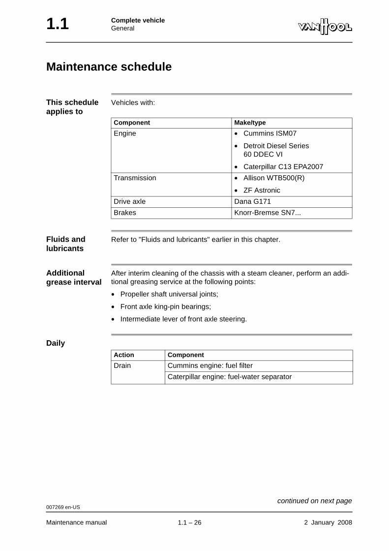
Maintenance schedule
This schedule applies to
Vehicles with:
Fluids and lubricants
Refer to "Fluids and lubricants" earlier in this chapter.
Additional grease interval
After interim cleaning of the chassis with a steam cleaner, perform an addi-tional greasing service at the following points:
• Propeller shaft universal joints;
• Front axle king-pin bearings;
• Intermediate lever of front axle steering.
Daily
Component Make/type
Engine • Cummins ISM07
• Detroit Diesel Series 60 DDEC VI
• Caterpillar C13 EPA2007
Transmission • Allison WTB500(R)
• ZF Astronic
Drive axle Dana G171
Brakes Knorr-Bremse SN7...
Action Component
Drain Cummins engine: fuel filter
Caterpillar engine: fuel-water separator
007269 en-US
Maintenance manual 2 January 2008
continued on next page.
1.1 – 26
Complete vehicleGeneral 1.1
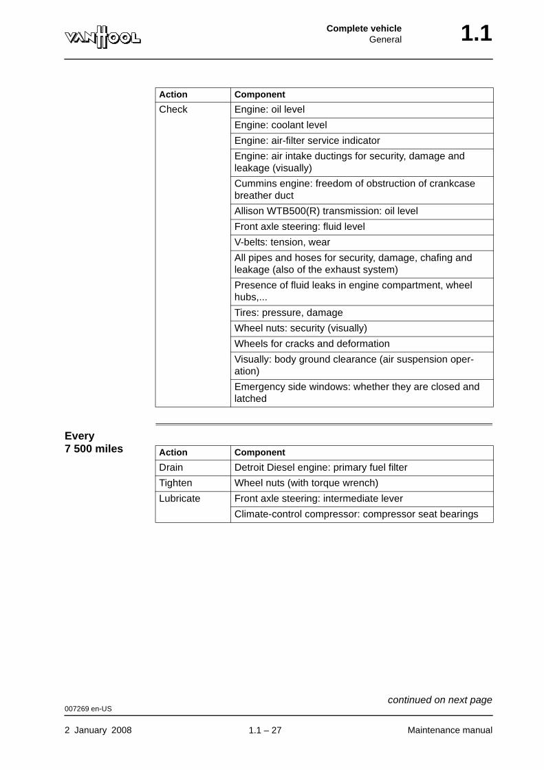
Every 7 500 miles
Check Engine: oil level
Engine: coolant level
Engine: air-filter service indicator
Engine: air intake ductings for security, damage and leakage (visually)
Cummins engine: freedom of obstruction of crankcase breather duct
Allison WTB500(R) transmission: oil level
Front axle steering: fluid level
V-belts: tension, wear
All pipes and hoses for security, damage, chafing and leakage (also of the exhaust system)
Presence of fluid leaks in engine compartment, wheel hubs,...
Tires: pressure, damage
Wheel nuts: security (visually)
Wheels for cracks and deformation
Visually: body ground clearance (air suspension oper-ation)
Emergency side windows: whether they are closed and latched
Action Component
Action Component
Drain Detroit Diesel engine: primary fuel filter
Tighten Wheel nuts (with torque wrench)
Lubricate Front axle steering: intermediate lever
Climate-control compressor: compressor seat bearings
007269 en-US
2 January 2008 Maintenance manual
continued on next page.
1.1 – 27
1.1 Complete vehicleGeneral
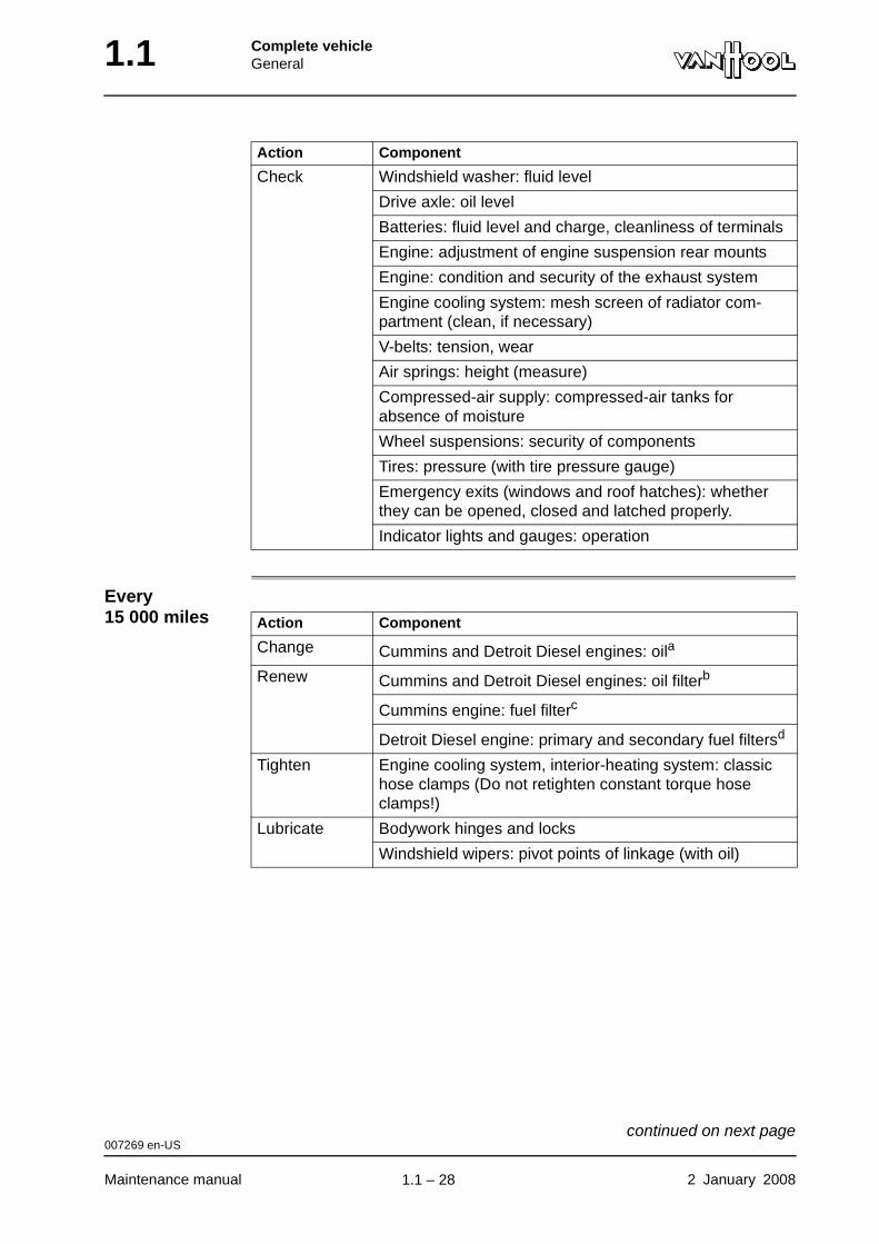
Every 15 000 miles
Check Windshield washer: fluid level
Drive axle: oil level
Batteries: fluid level and charge, cleanliness of terminals
Engine: adjustment of engine suspension rear mounts
Engine: condition and security of the exhaust system
Engine cooling system: mesh screen of radiator com-partment (clean, if necessary)
V-belts: tension, wear
Air springs: height (measure)
Compressed-air supply: compressed-air tanks for absence of moisture
Wheel suspensions: security of components
Tires: pressure (with tire pressure gauge)
Emergency exits (windows and roof hatches): whether they can be opened, closed and latched properly.
Indicator lights and gauges: operation
Action Component
Action Component
Change Cummins and Detroit Diesel engines: oila
Renew Cummins and Detroit Diesel engines: oil filterb
Cummins engine: fuel filterc
Detroit Diesel engine: primary and secondary fuel filtersd
Tighten Engine cooling system, interior-heating system: classic hose clamps (Do not retighten constant torque hose clamps!)
Lubricate Bodywork hinges and locks
Windshield wipers: pivot points of linkage (with oil)
007269 en-US
Maintenance manual 2 January 2008
continued on next page.
1.1 – 28
Complete vehicleGeneral 1.1
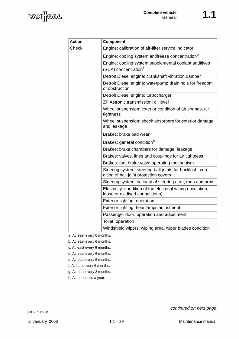
Check Engine: calibration of air-filter service indicator
Engine: cooling system antifreeze concentratione
Engine: cooling system supplemental coolant additives
(SCA) concentrationf
Detroit Diesel engine: crankshaft vibration damper
Detroit Diesel engine: waterpump drain hole for freedom of obstruction
Detroit Diesel engine: turbocharger
ZF Astronic transmission: oil level
Wheel suspension: exterior condition of air springs, air tightness
Wheel suspension: shock absorbers for exterior damage and leakage
Brakes: brake pad wearg
Brakes: general conditionh
Brakes: brake chambers for damage, leakage
Brakes: valves, lines and couplings for air tightness
Brakes: foot brake valve operating mechanism
Steering system: steering ball-joints for backlash, con-dition of ball-joint protection covers
Steering system: security of steering gear, rods and arms
Electricity: condition of the electrical wiring (insulation, loose or oxidised connections)
Exterior lighting: operation
Exterior lighting: headlamps adjustment
Passenger door: operation and adjustment
Toilet: operation
Windshield wipers: wiping area, wiper blades condition
a. At least every 6 months.
b. At least every 6 months.
c. At least every 6 months.
d. At least every 6 months.
e. At least every 6 months.
f. At least every 6 months.
g. At least every 3 months.
h. At least once a year.
Action Component
007269 en-US
2 January 2008 Maintenance manual
continued on next page.
1.1 – 29
1.1 Complete vehicleGeneral
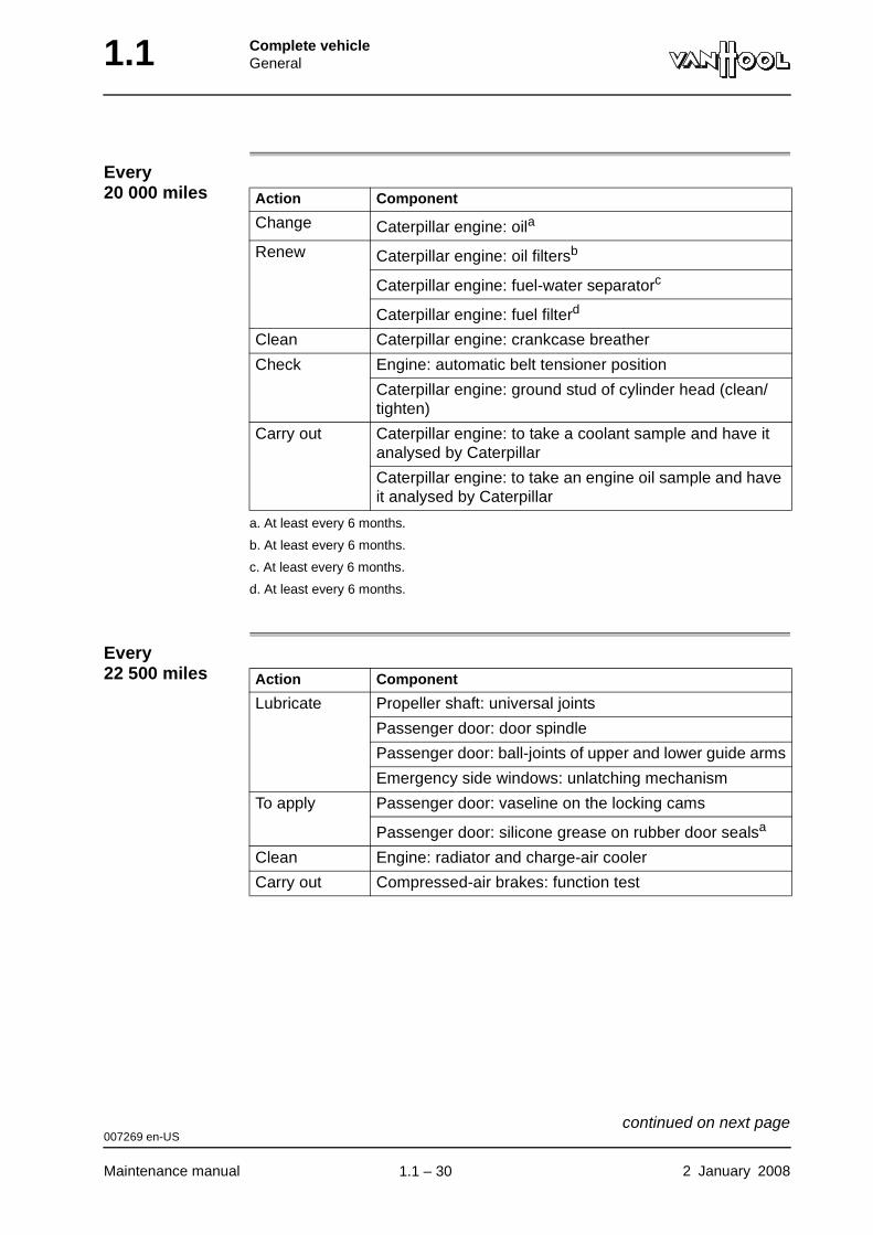
Every 20 000 miles
Every 22 500 miles
Action Component
Change Caterpillar engine: oila
a. At least every 6 months.
Renew Caterpillar engine: oil filtersb
b. At least every 6 months.
Caterpillar engine: fuel-water separatorc
c. At least every 6 months.
Caterpillar engine: fuel filterd
d. At least every 6 months.
Clean Caterpillar engine: crankcase breather
Check Engine: automatic belt tensioner position
Caterpillar engine: ground stud of cylinder head (clean/tighten)
Carry out Caterpillar engine: to take a coolant sample and have it analysed by Caterpillar
Caterpillar engine: to take an engine oil sample and have it analysed by Caterpillar
Action Component
Lubricate Propeller shaft: universal joints
Passenger door: door spindle
Passenger door: ball-joints of upper and lower guide arms
Emergency side windows: unlatching mechanism
To apply Passenger door: vaseline on the locking cams
Passenger door: silicone grease on rubber door sealsa
Clean Engine: radiator and charge-air cooler
Carry out Compressed-air brakes: function test
007269 en-US
Maintenance manual 2 January 2008
continued on next page.
1.1 – 30
Complete vehicleGeneral 1.1
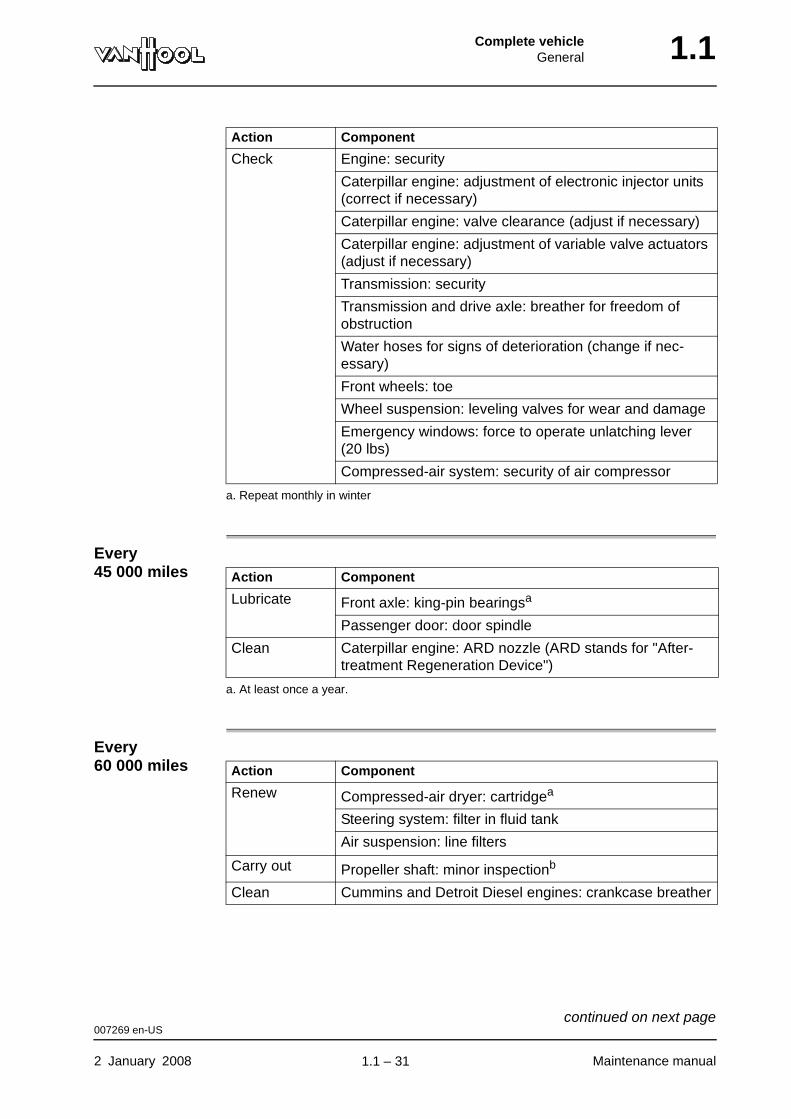
Every 45 000 miles
Every 60 000 miles
Check Engine: security
Caterpillar engine: adjustment of electronic injector units (correct if necessary)
Caterpillar engine: valve clearance (adjust if necessary)
Caterpillar engine: adjustment of variable valve actuators (adjust if necessary)
Transmission: security
Transmission and drive axle: breather for freedom of obstruction
Water hoses for signs of deterioration (change if nec-essary)
Front wheels: toe
Wheel suspension: leveling valves for wear and damage
Emergency windows: force to operate unlatching lever (20 lbs)
Compressed-air system: security of air compressor
a. Repeat monthly in winter
Action Component
Action Component
Lubricate Front axle: king-pin bearingsa
a. At least once a year.
Passenger door: door spindle
Clean Caterpillar engine: ARD nozzle (ARD stands for "After-treatment Regeneration Device")
Action Component
Renew Compressed-air dryer: cartridgea
Steering system: filter in fluid tank
Air suspension: line filters
Carry out Propeller shaft: minor inspectionb
Clean Cummins and Detroit Diesel engines: crankcase breather
007269 en-US
2 January 2008 Maintenance manual
continued on next page.
1.1 – 31
1.1 Complete vehicleGeneral
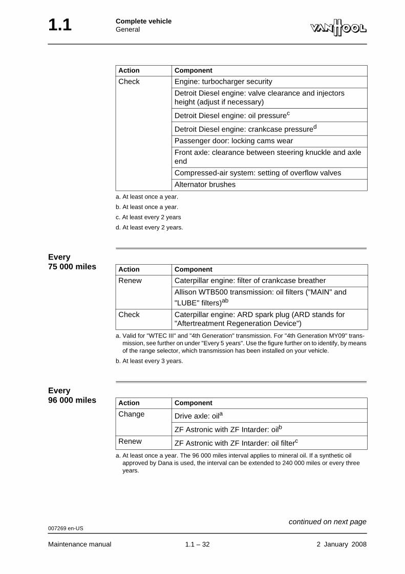
Every 75 000 miles
Every 96 000 miles
Check Engine: turbocharger security
Detroit Diesel engine: valve clearance and injectors height (adjust if necessary)
Detroit Diesel engine: oil pressurec
Detroit Diesel engine: crankcase pressured
Passenger door: locking cams wear
Front axle: clearance between steering knuckle and axle end
Compressed-air system: setting of overflow valves
Alternator brushes
a. At least once a year.
b. At least once a year.
c. At least every 2 years
d. At least every 2 years.
Action Component
Action Component
Renew Caterpillar engine: filter of crankcase breather
Allison WTB500 transmission: oil filters ("MAIN" and
"LUBE" filters)ab
a. Valid for "WTEC III" and "4th Generation" transmission. For "4th Generation MY09" trans-mission, see further on under "Every 5 years". Use the figure further on to identify, by means of the range selector, which transmission has been installed on your vehicle.
b. At least every 3 years.
Check Caterpillar engine: ARD spark plug (ARD stands for "Aftertreatment Regeneration Device")
Action Component
Change Drive axle: oila
a. At least once a year. The 96 000 miles interval applies to mineral oil. If a synthetic oil approved by Dana is used, the interval can be extended to 240 000 miles or every three years.
ZF Astronic with ZF Intarder: oilb
Renew ZF Astronic with ZF Intarder: oil filterc
007269 en-US
Maintenance manual 2 January 2008
continued on next page.
1.1 – 32
Complete vehicleGeneral 1.1
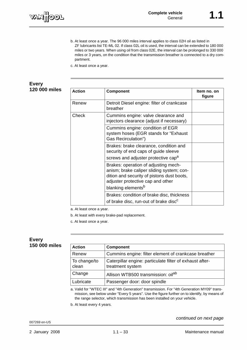
Every 120 000 miles
Every 150 000 miles
b. At least once a year. The 96 000 miles interval applies to class 02H oil as listed in ZF lubricants list TE-ML 02. If class 02L oil is used, the interval can be extended to 180 000 miles or two years. When using oil from class 02E, the interval can be prolonged to 330 000 miles or 3 years, on the condition that the transmission breather is connected to a dry com-partment.
c. At least once a year.
Action Component Item no. on figure
Renew Detroit Diesel engine: filter of crankcase breather
Check Cummins engine: valve clearance and injectors clearance (adjust if necessary)
Cummins engine: condition of EGR system hoses (EGR stands for "Exhaust Gas Recirculation")
Brakes: brake clearance, condition and security of end caps of guide sleeve
screws and adjuster protective capa
a. At least once a year.
Brakes: operation of adjusting mech-anism; brake caliper sliding system; con-dition and security of pistons dust boots, adjuster protective cap and other
blanking elementsb
b. At least with every brake-pad replacement.
Brakes: condition of brake disc, thickness
of brake disc, run-out of brake discc
c. At least once a year.
Action Component
Renew Cummins engine: filter element of crankcase breather
To change/to clean
Caterpillar engine: particulate filter of exhaust after-treatment system
Change Allison WTB500 transmission: oilab
a. Valid for "WTEC III" and "4th Generation" transmission. For "4th Generation MY09" trans-mission, see below under "Every 5 years". Use the figure further on to identify, by means of the range selector, which transmission has been installed on your vehicle.
b. At least every 4 years.
Lubricate Passenger door: door spindle
007269 en-US
2 January 2008 Maintenance manual
continued on next page.
1.1 – 33
1.1 Complete vehicleGeneral
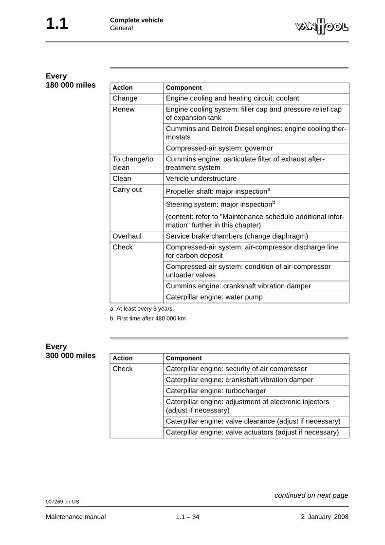
Every 180 000 miles
Every 300 000 miles
Action Component
Change Engine cooling and heating circuit: coolant
Renew Engine cooling system: filler cap and pressure relief cap of expansion tank
Cummins and Detroit Diesel engines: engine cooling ther-mostats
Compressed-air system: governor
To change/to clean
Cummins engine: particulate filter of exhaust after-treatment system
Clean Vehicle understructure
Carry out Propeller shaft: major inspectiona
a. At least every 3 years.
Steering system: major inspectionb
(content: refer to "Maintenance schedule additional infor-mation" further in this chapter)
b. First time after 480 000 km
Overhaul Service brake chambers (change diaphragm)
Check Compressed-air system: air-compressor discharge line for carbon deposit
Compressed-air system: condition of air-compressor unloader valves
Cummins engine: crankshaft vibration damper
Caterpillar engine: water pump
Action Component
Check Caterpillar engine: security of air compressor
Caterpillar engine: crankshaft vibration damper
Caterpillar engine: turbocharger
Caterpillar engine: adjustment of electronic injectors (adjust if necessary)
Caterpillar engine: valve clearance (adjust if necessary)
Caterpillar engine: valve actuators (adjust if necessary)
007269 en-US
Maintenance manual 2 January 2008
continued on next page.
1.1 – 34
Complete vehicleGeneral 1.1
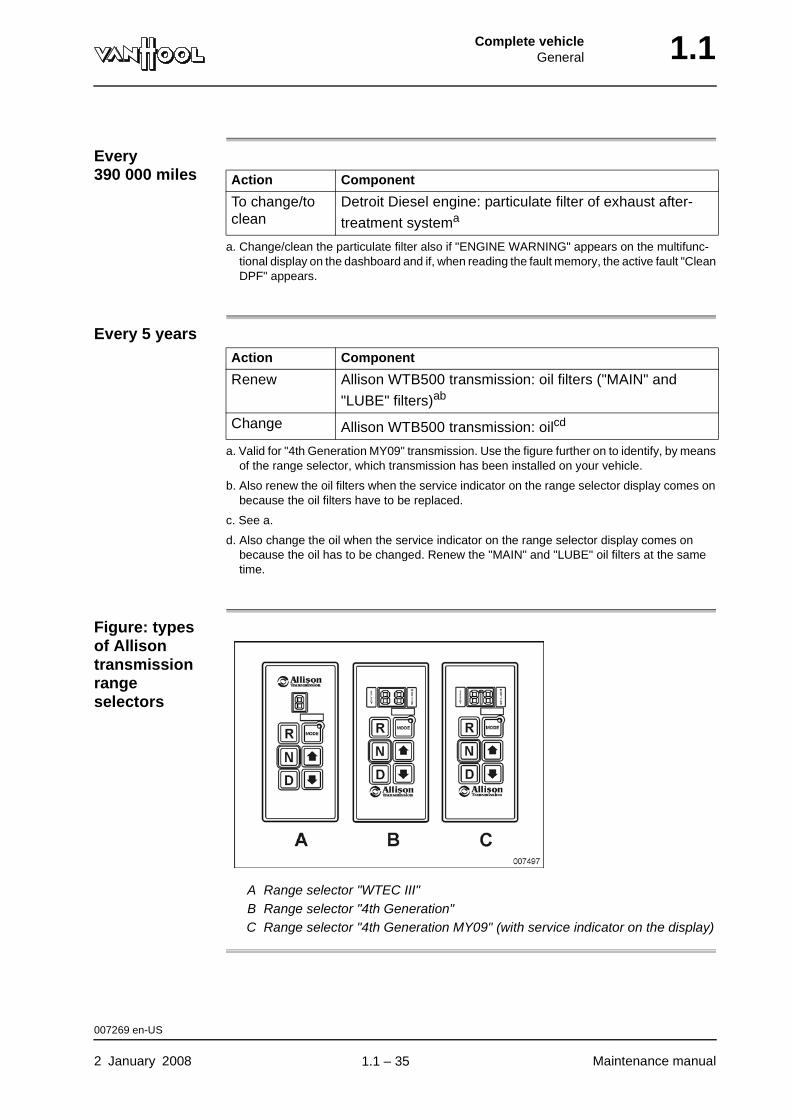
Every 390 000 miles
Every 5 years
Figure: types of Allison transmission range selectors
A Range selector "WTEC III"B Range selector "4th Generation"C Range selector "4th Generation MY09" (with service indicator on the display)
Action Component
To change/to clean
Detroit Diesel engine: particulate filter of exhaust after-
treatment systema
a. Change/clean the particulate filter also if "ENGINE WARNING" appears on the multifunc-tional display on the dashboard and if, when reading the fault memory, the active fault "Clean DPF" appears.
Action Component
Renew Allison WTB500 transmission: oil filters ("MAIN" and
"LUBE" filters)ab
a. Valid for "4th Generation MY09" transmission. Use the figure further on to identify, by means of the range selector, which transmission has been installed on your vehicle.
b. Also renew the oil filters when the service indicator on the range selector display comes on because the oil filters have to be replaced.
Change Allison WTB500 transmission: oilcd
c. See a.
d. Also change the oil when the service indicator on the range selector display comes on because the oil has to be changed. Renew the "MAIN" and "LUBE" oil filters at the same time.
007269 en-US
2 January 2008 Maintenance manual
.
1.1 – 35
1.1 Complete vehicleGeneral
Maintenance schedule additional information
"Steering system major inspection" contains:
• To check maximum steering pump pressure.
• To check steering pump flow.
• To check/set hydraulic steering lock.
• To check steering gear pressure.
• To check steering gear for internal leakage.
• To check return time of power steering valve.
• To check play on steering wheel.
• To check steering gear mesh load.
• To check straight-ahead position of wheels.
• To check steering lock angles.
• To check steering column bearings for play.
• To check universal joints and flex couplings.
001229 en-US
Maintenance manual 2 January 2008
.
1.1 – 36
Complete vehicleGeneral 1.1
Maintenance schedule for the climate-control system
General • Have the climate-control system checked annually by a heating and refrig-erating technician at the beginning of the hot season. All work listed under "Annual" must be carried out.
• Vehicles with coolant heater: have the coolant heater checked annually by a recognised Proheat technician at the start of the cold season.
• Vehicles with coolant heater: check the outlet of the coolant heater at every service. The outlet must be unobstructed, otherwise it will prevent proper operation of the coolant heater and could cause damage.
Preventative off-season operation
• Let the climate-control compressor run for 15 to 20 minutes once per month, even during the cold season, i.e. with the clutch engaged.
• Vehicles with coolant heater: let the heater run for about 10 minutes once per month, even during the hot season, while the engine is cold.
Fluids and lubricants
Refer to "Fluids and lubricants" earlier in this chapter.
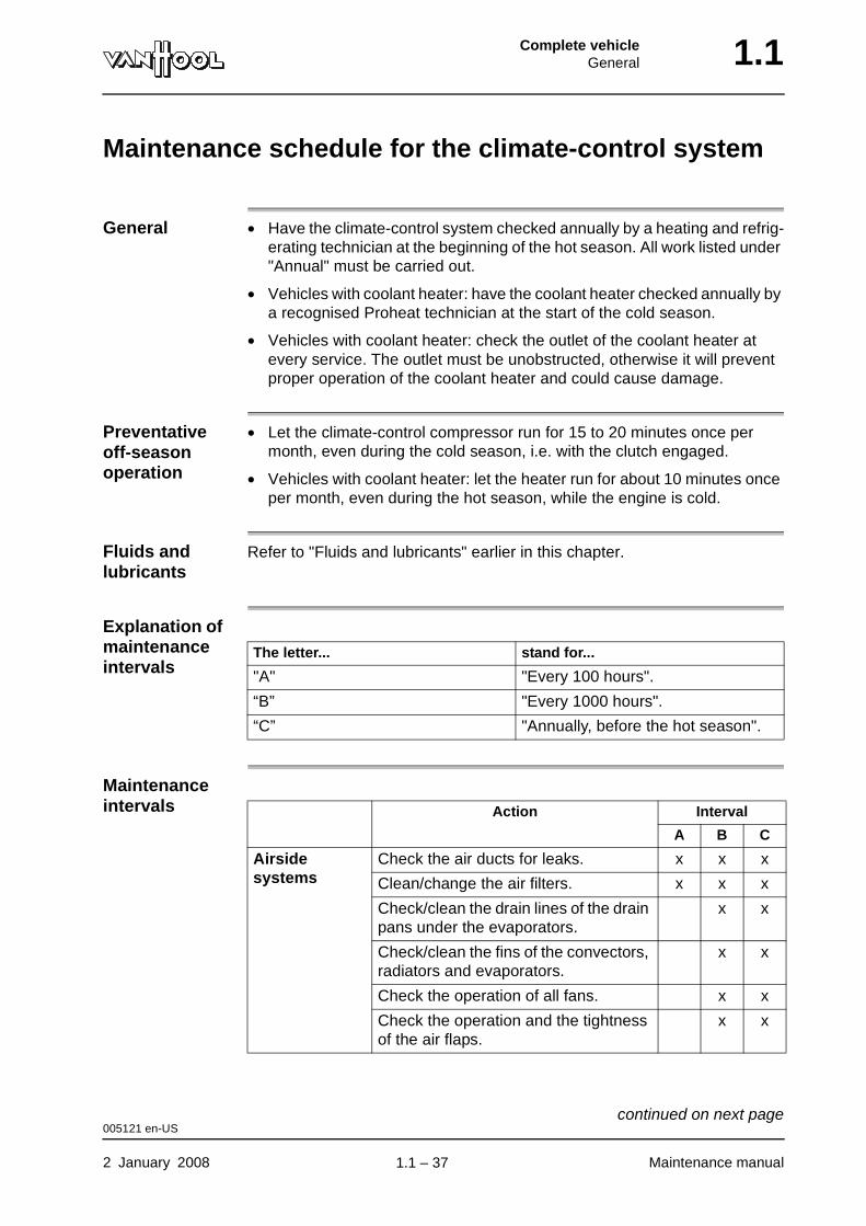
Explanation of maintenance intervals
Maintenance intervals
The letter... stand for...
"A" "Every 100 hours".
“B” "Every 1000 hours".
“C” "Annually, before the hot season".
Action Interval
A B C
Airside systems
Check the air ducts for leaks. x x x
Clean/change the air filters. x x x
Check/clean the drain lines of the drain pans under the evaporators.
x x
Check/clean the fins of the convectors, radiators and evaporators.
x x
Check the operation of all fans. x x
Check the operation and the tightness of the air flaps.
x x
005121 en-US
2 January 2008 Maintenance manual
continued on next page.
1.1 – 37

1.1 Complete vehicleGeneral
Water circuit Check the operation of the circulating pumps.
x x
Check the condition of the water hoses.
x x
Refrigerant circuit
Check operating pressures and perfor-mance.
x
Check the compressor clutch bearing. x x
Check/clean the condenser cooling fins.
x x
Check the condenser cooling fans. x x
Check the operation of the high- and low-pressure switches.
x x
Change the filter/dryer. x
Check the refrigerant lines and line couplings. If necessary, tighten the coupling.
x
Check the hoses for leaking com-pressor oil or refrigerant.
x x
Check the oil level in the compressor. Change the compressor oil.
x
Check the sight-glass to see if the system has sufficient refrigerant.
x
Check that the climate-control com-pressor is securely mounted.
x x
Control system
Check that the system can perform all of the basic functions.
x
Carry out a complete function test. x
Check the condition of the electrical cables, connectors and warning lights.
x
With compressed air, blow through the inside-air temperature sensor(s) by the openings in the housing.
x
Action Interval
A B C
005121 en-US
Maintenance manual 2 January 2008
.
1.1 – 38
Complete vehicleGeneral 1.1
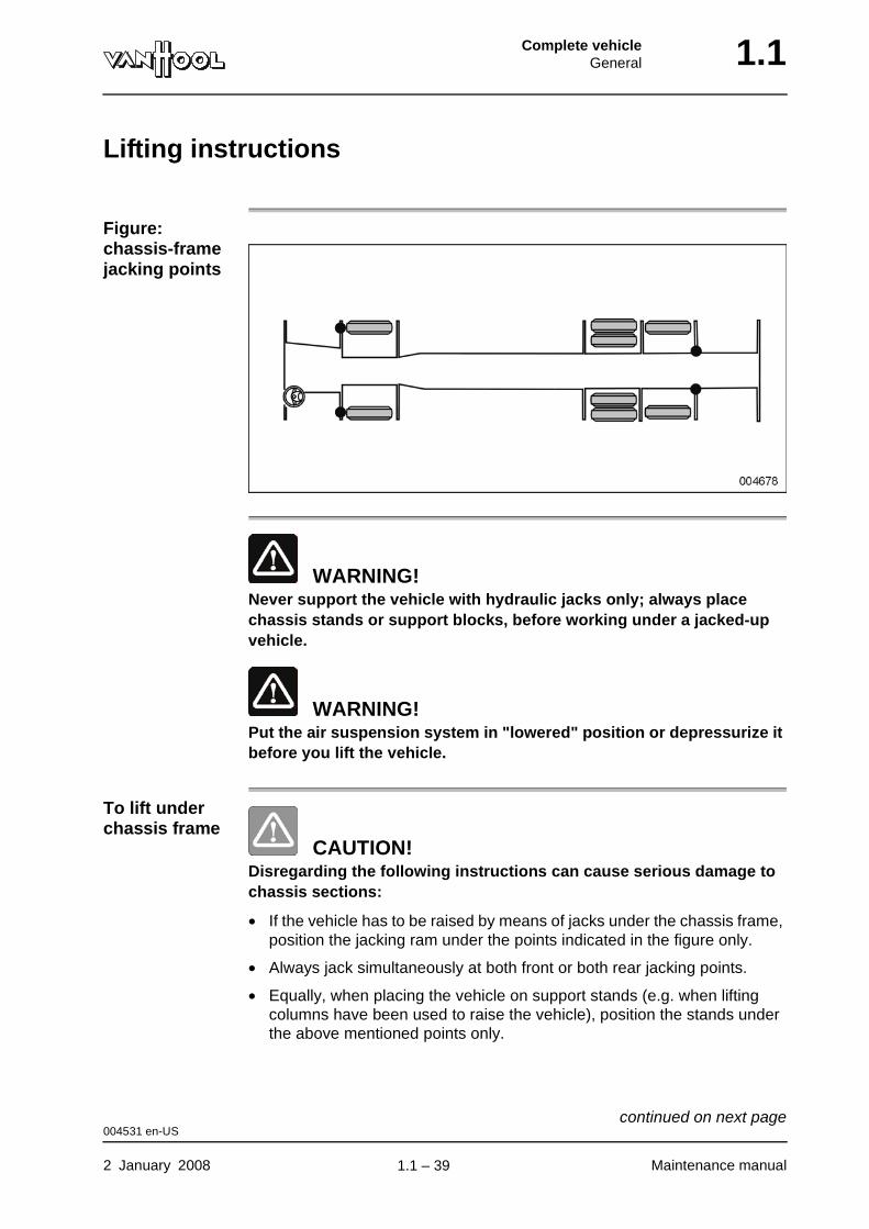
Lifting instructions
Figure: chassis-frame jacking points
WARNING!Never support the vehicle with hydraulic jacks only; always place chassis stands or support blocks, before working under a jacked-up vehicle.
WARNING!Put the air suspension system in "lowered" position or depressurize it before you lift the vehicle.
To lift under chassis frame
CAUTION!Disregarding the following instructions can cause serious damage to chassis sections:
• If the vehicle has to be raised by means of jacks under the chassis frame, position the jacking ram under the points indicated in the figure only.
• Always jack simultaneously at both front or both rear jacking points.
• Equally, when placing the vehicle on support stands (e.g. when lifting columns have been used to raise the vehicle), position the stands under the above mentioned points only.
004531 en-US
2 January 2008 Maintenance manual
continued on next page.
1.1 – 39
1.1 Complete vehicleGeneral
To raise the vehicle with lifting columns WARNING!
The four (or six) lifting columns have to move at the same speed, so that the vehicle remains level while it is being raised or lowered
To raise the vehicle under the drive axle
If the drive axle has to be raised, it is best to place a central jack with a dished head under the middle of the axle banjo.
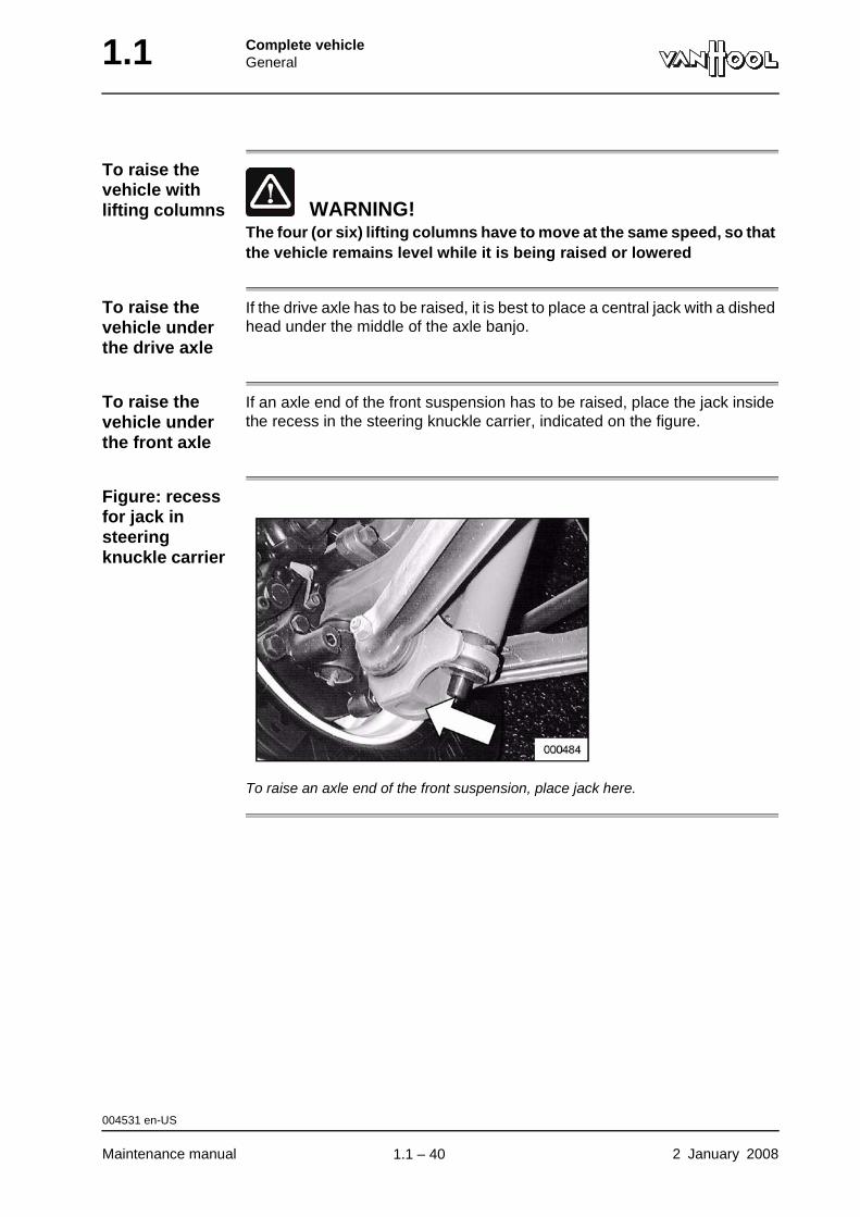
To raise the vehicle under the front axle
If an axle end of the front suspension has to be raised, place the jack inside the recess in the steering knuckle carrier, indicated on the figure.
Figure: recess for jack in steering knuckle carrier
To raise an axle end of the front suspension, place jack here.
004531 en-US
Maintenance manual 2 January 2008
.
1.1 – 40
Complete vehicleGeneral 1.1
Towing instructions
Guidelines • Before towing, always disconnect the propeller shaft at the drive axle end or remove the two drive-axle half shafts. In case of damage inside the drive axle, the vehicle has to be towed from the back.
• During the towing procedure, the vehicle air system can be supplied with compressed air by the towing vehicle through a hose coupling (refer to "To charge compressed-air tanks externally").
004532 en-US
2 January 2008 Maintenance manual
.
1.1 – 41
1.1 Complete vehicleGeneral
To lift and tow vehicle with recovery vehicle equipped with under-arm lift
Equipment condition
To read towing conditions (refer to "Towing instructions").
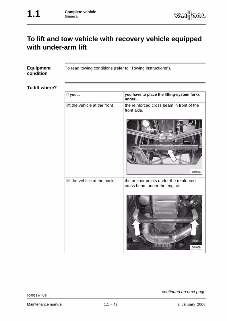
To lift where?If you... you have to place the lifting-system forks
under...
lift the vehicle at the front the reinforced cross beam in front of the front axle.
lift the vehicle at the back the anchor points under the reinforced cross beam under the engine.
004533 en-US
Maintenance manual 2 January 2008
continued on next page.
1.1 – 42
Complete vehicleGeneral 1.1
WARNING!Do not carry out towing procedures that may be hazardous to other road users or that may cause damage to the vehicle.
WARNING!Follow the legislation that applies to towed vehicles.
Procedure
Step Action
1 Manoeuvre frame of under-arm lift under reinforced cross beam.
2 Lift the vehicle.
004533 en-US
2 January 2008 Maintenance manual
.
1.1 – 43
1.1 Complete vehicleGeneral
External cleaning of vehicle units
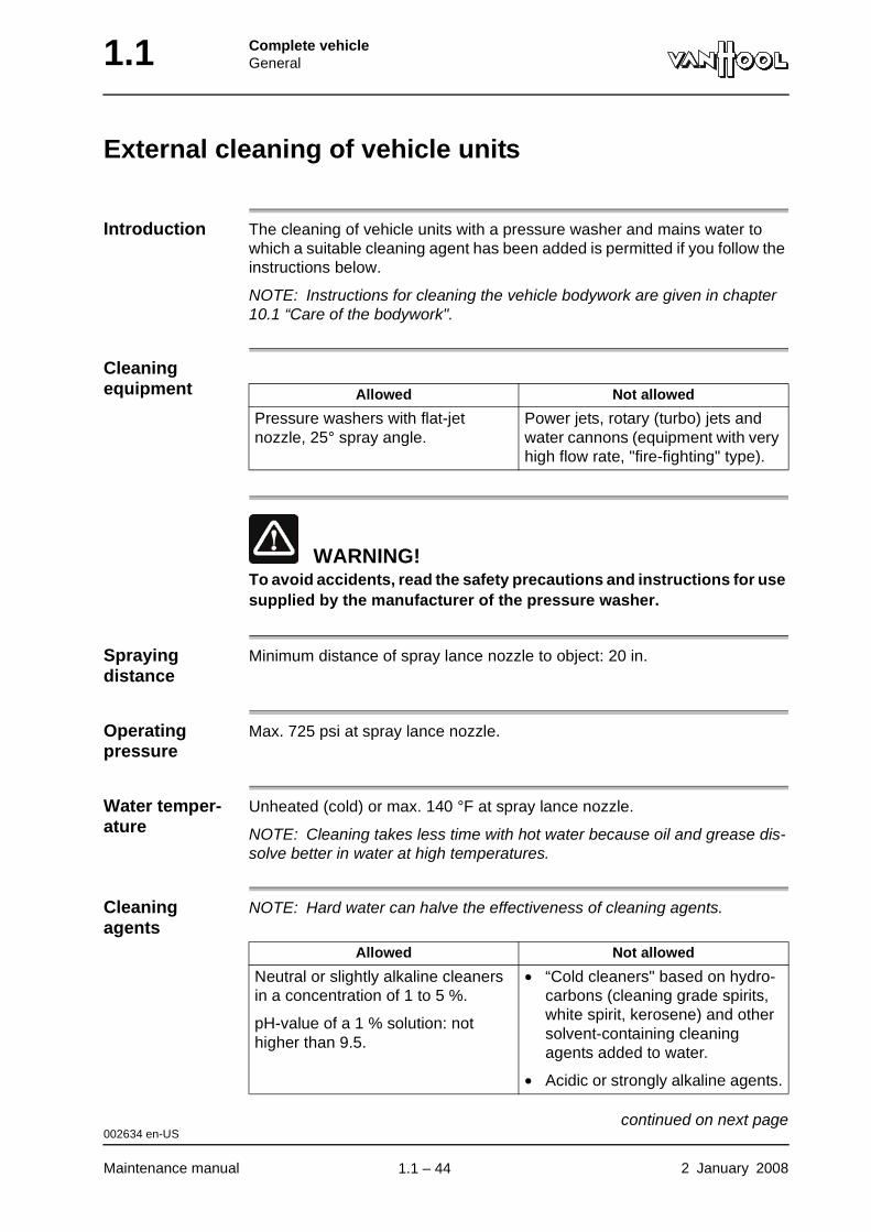
Introduction The cleaning of vehicle units with a pressure washer and mains water to which a suitable cleaning agent has been added is permitted if you follow the instructions below.
NOTE: Instructions for cleaning the vehicle bodywork are given in chapter 10.1 “Care of the bodywork".
Cleaning equipment
WARNING!To avoid accidents, read the safety precautions and instructions for use supplied by the manufacturer of the pressure washer.
Spraying distance
Minimum distance of spray lance nozzle to object: 20 in.
Operating pressure
Max. 725 psi at spray lance nozzle.
Water temper-ature
Unheated (cold) or max. 140 °F at spray lance nozzle.
NOTE: Cleaning takes less time with hot water because oil and grease dis-solve better in water at high temperatures.
Cleaning agents
NOTE: Hard water can halve the effectiveness of cleaning agents.
Allowed Not allowed
Pressure washers with flat-jet nozzle, 25° spray angle.
Power jets, rotary (turbo) jets and water cannons (equipment with very high flow rate, "fire-fighting" type).
Allowed Not allowed
Neutral or slightly alkaline cleaners in a concentration of 1 to 5 %.
pH-value of a 1 % solution: not higher than 9.5.
• “Cold cleaners" based on hydro-carbons (cleaning grade spirits, white spirit, kerosene) and other solvent-containing cleaning agents added to water.
• Acidic or strongly alkaline agents.
002634 en-US
Maintenance manual 2 January 2008
continued on next page.
1.1 – 44
Complete vehicleGeneral 1.1
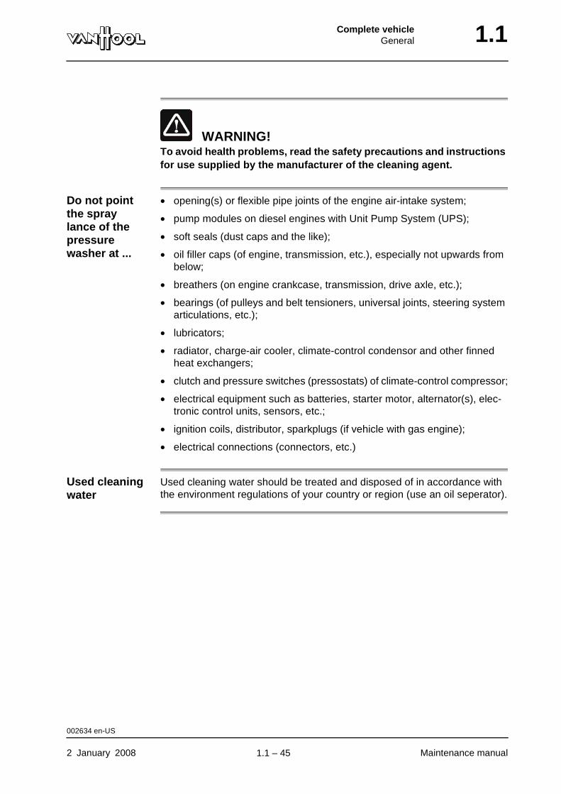
WARNING!To avoid health problems, read the safety precautions and instructions for use supplied by the manufacturer of the cleaning agent.
Do not point the spray lance of the pressure washer at ...
• opening(s) or flexible pipe joints of the engine air-intake system;
• pump modules on diesel engines with Unit Pump System (UPS);
• soft seals (dust caps and the like);
• oil filler caps (of engine, transmission, etc.), especially not upwards from below;
• breathers (on engine crankcase, transmission, drive axle, etc.);
• bearings (of pulleys and belt tensioners, universal joints, steering system articulations, etc.);
• lubricators;
• radiator, charge-air cooler, climate-control condensor and other finned heat exchangers;
• clutch and pressure switches (pressostats) of climate-control compressor;
• electrical equipment such as batteries, starter motor, alternator(s), elec-tronic control units, sensors, etc.;
• ignition coils, distributor, sparkplugs (if vehicle with gas engine);
• electrical connections (connectors, etc.)
Used cleaning water
Used cleaning water should be treated and disposed of in accordance with the environment regulations of your country or region (use an oil seperator).
002634 en-US
2 January 2008 Maintenance manual
.
1.1 – 45
1.1 Complete vehicleGeneral
This page has been intentionally left blank.
002634 en-US
Maintenance manual 2 January 20081.1 – 46
Part 2 - Traction engine
Overview
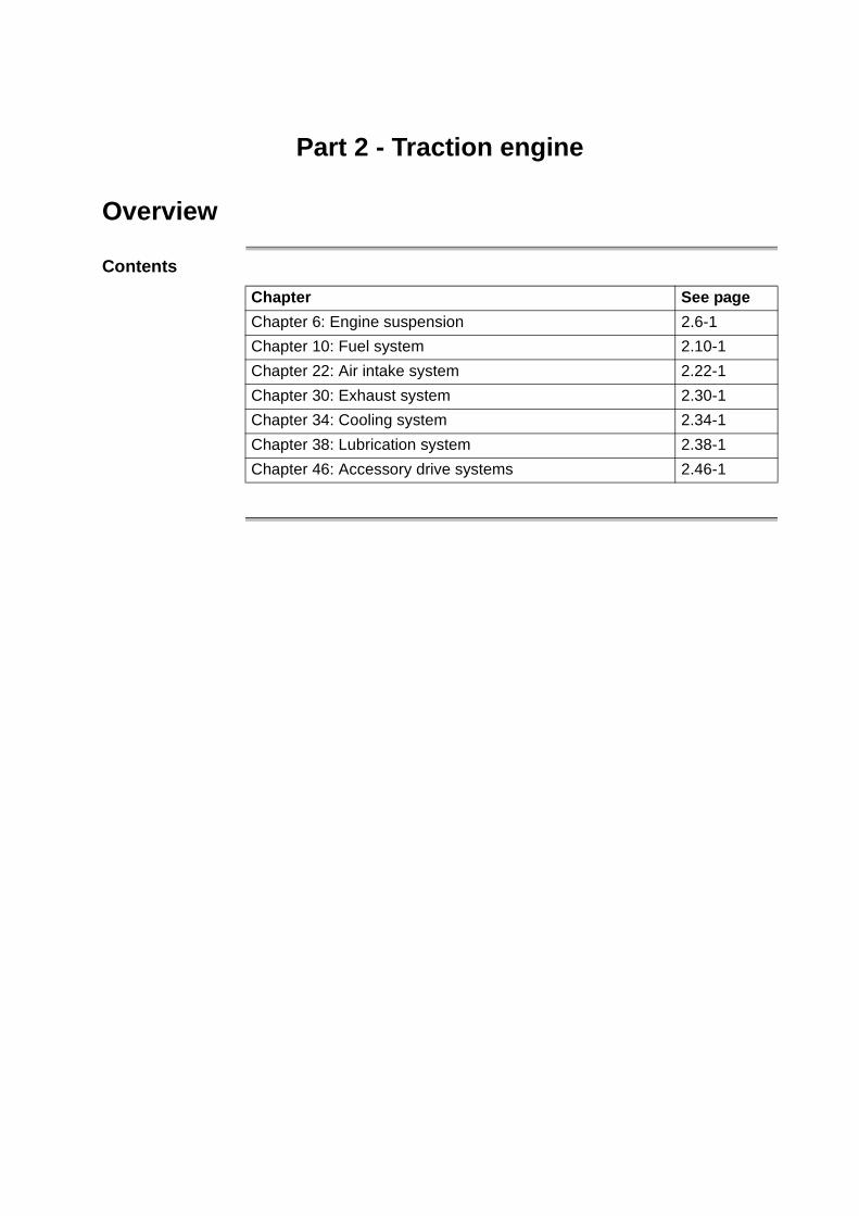
Contents
Chapter See page
Chapter 6: Engine suspension 2.6-1
Chapter 10: Fuel system 2.10-1
Chapter 22: Air intake system 2.22-1
Chapter 30: Exhaust system 2.30-1
Chapter 34: Cooling system 2.34-1
Chapter 38: Lubrication system 2.38-1
Chapter 46: Accessory drive systems 2.46-1

Traction engineEngine suspension 2.6
Chapter 6: Engine suspension
Overview
Introduction This chapter deals with the engine suspension.
Number of pages
4
Chapter publi-cation date
2 January 2008
Contents
Topic See page
To check engine security 2.6-2
To check adjustment of rear engine mounts 2.6-3
Technical data: engine suspension 2.6-4
2 January 2008 Maintenance manual
.
2.6 – 1

2.6 Traction engineEngine suspension
To check engine security
Tightening torques
Refer to "Technical data" at the end of this chapter.
000127 en-US
Maintenance manual 2 January 2008
.
2.6 – 2
Traction engineEngine suspension 2.6
To check adjustment of rear engine mounts
To be carried out when?
Refer to chapter 1.1, "Maintenance schedule".
To check what?
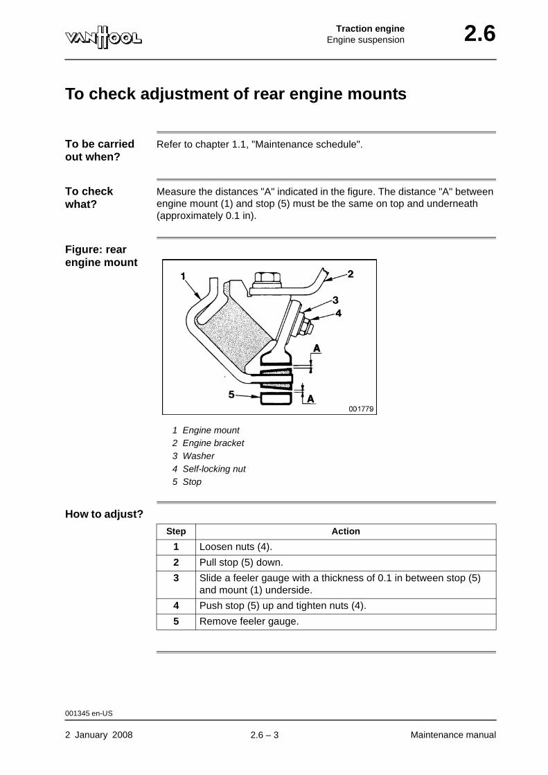
Measure the distances "A" indicated in the figure. The distance "A" between engine mount (1) and stop (5) must be the same on top and underneath (approximately 0.1 in).
Figure: rear engine mount
1 Engine mount2 Engine bracket3 Washer4 Self-locking nut5 Stop
How to adjust?
Step Action
1 Loosen nuts (4).
2 Pull stop (5) down.
3 Slide a feeler gauge with a thickness of 0.1 in between stop (5) and mount (1) underside.
4 Push stop (5) up and tighten nuts (4).
5 Remove feeler gauge.
001345 en-US
2 January 2008 Maintenance manual
.
2.6 – 3
2.6 Traction engineEngine suspension
Technical data: engine suspension
Figure: tightening torques
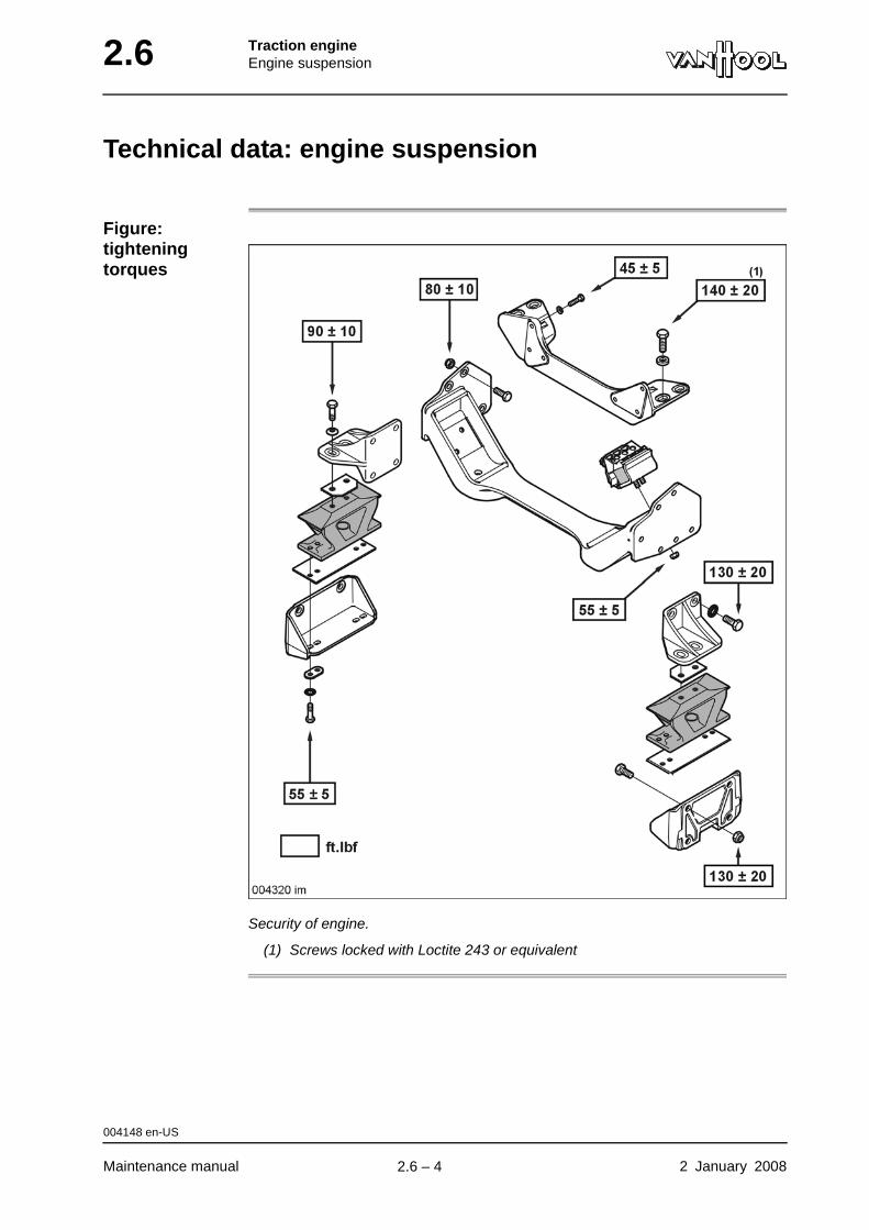
Security of engine.
(1) Screws locked with Loctite 243 or equivalent
004148 en-US
Maintenance manual 2 January 2008
.
2.6 – 4

Traction engineFuel system 2.10
Chapter 10: Fuel system
Overview
Number of pages
10
Chapter publi-cation date
2 January 2008
Contents
Topic See page
EDC system: self-diagnosis 2.10-2
EDC system: fault reproduction 2.10-3
EDC system: to read out fault memory using flash code 2.10-5
To drain fuel filter 2.10-8
To change fuel filter 2.10-9
2 January 2008 Maintenance manual
.
2.10 – 1

2.10 Traction engineFuel system
EDC system: self-diagnosis
Introduction The electronic control unit contains a self-diagnostic feature. The electronics constantly monitor the correct operation of the system and faults are stored in a memory. The self-diagnosis feature makes troubleshooting easier.
How to read fault memory?
You can read the fault memory using:
• the engine diagnostics lamps on the diagnostics panel in the front junction box;
• a special diagnostic tool from Cummins (refer to Cummins service liter-ature).
004973 en-US
Maintenance manual 2 January 2008
.
2.10 – 2
Traction engineFuel system 2.10
EDC system: fault reproduction
Active fault An active fault is a fault that exists during diagnostics.
Engine diagnostic lamps
On request, the engine diagnostic lamps on the diagnostics panel in the front junction box show the active faults through a flash code.
What does a flash code look like?
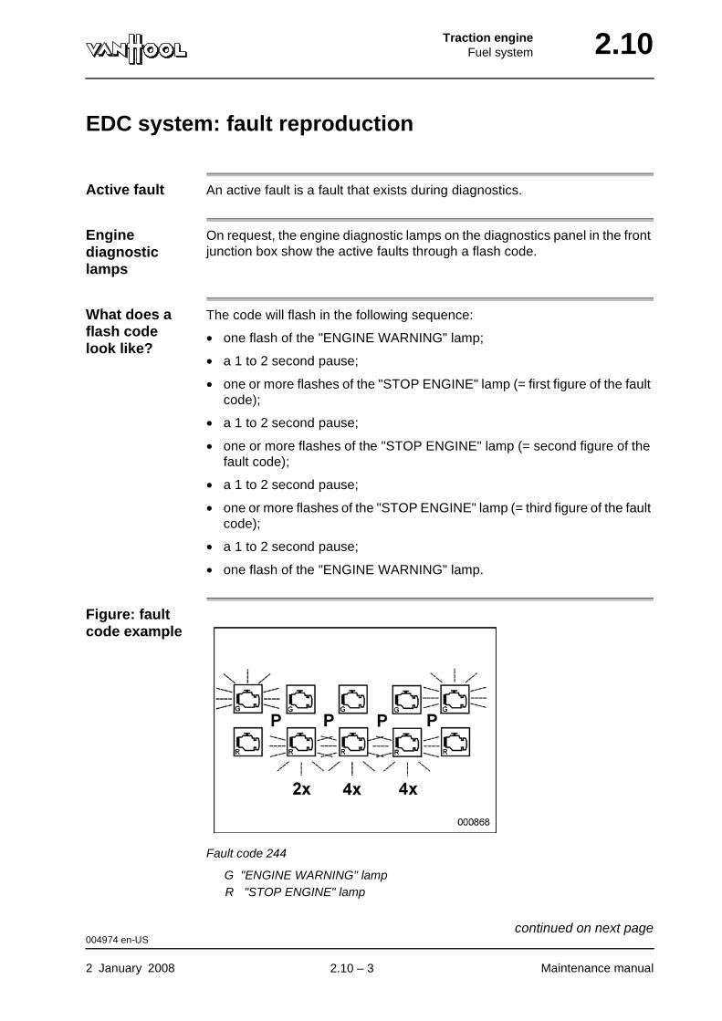
The code will flash in the following sequence:
• one flash of the "ENGINE WARNING" lamp;
• a 1 to 2 second pause;
• one or more flashes of the "STOP ENGINE" lamp (= first figure of the fault code);
• a 1 to 2 second pause;
• one or more flashes of the "STOP ENGINE" lamp (= second figure of the fault code);
• a 1 to 2 second pause;
• one or more flashes of the "STOP ENGINE" lamp (= third figure of the fault code);
• a 1 to 2 second pause;
• one flash of the "ENGINE WARNING" lamp.
Figure: fault code example
Fault code 244
G "ENGINE WARNING" lampR "STOP ENGINE" lamp
004974 en-US
2 January 2008 Maintenance manual
continued on next page.
2.10 – 3

2.10 Traction engineFuel system
004974 en-US
Maintenance manual 2 January 2008
.
2.10 – 4
Traction engineFuel system 2.10
EDC system: to read out fault memory using flash code
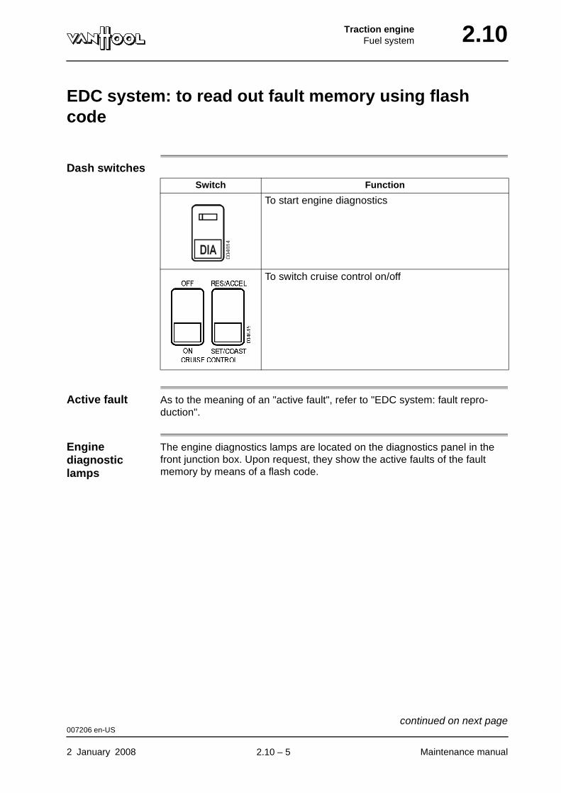
Dash switches
Active fault As to the meaning of an "active fault", refer to "EDC system: fault repro-duction".
Engine diagnostic lamps
The engine diagnostics lamps are located on the diagnostics panel in the front junction box. Upon request, they show the active faults of the fault memory by means of a flash code.
Switch Function
To start engine diagnostics
To switch cruise control on/off
007206 en-US
2 January 2008 Maintenance manual
continued on next page.
2.10 – 5

2.10 Traction engineFuel system
Figure: components for engine diagnostics
Diagnostics panel in front junction box (EKF)
1 "STOP ENGINE" lamp2 "ENGINE WARNING" lamp3 Engine diagnostic socket
To call up flash code
Several active faults
Each fault code is shown three times. After that, the following code is shown.
Step Action
1 Switch on on-board voltage.
2 Unlock the diagnostics switch on the dashboard and press it.
The diagnostics lamps show the contents of the fault memory.
• In the case of an active fault: both diagnostics lamps come on momentarily, then the fault code is shown ("ENGINE WARNING" lamp (2) flashes once, then "STOP ENGINE" lamp (1) gives the flash code).
• If there are no active faults: “ENGINE WARNING” lamp (2) and “STOP ENGINE” lamp (1) come on and remain lit.
If you want to call the ... yourself put the...
next code “RES/ACCEL-SET/COAST” switch on the dashboard momentarily in the “RES/ACCEL” position.
previous code “RES/ACCEL-SET/COAST” switch on the dashboard momentarily in the “SET/COAST” position.
007206 en-US
Maintenance manual 2 January 2008
continued on next page.
2.10 – 6
Traction engineFuel system 2.10
List with fault codes
Refer to Cummins literature.
007206 en-US
2 January 2008 Maintenance manual
.
2.10 – 7

2.10 Traction engineFuel system
To drain fuel filter
To be carried out when?
Refer to chapter 1.1, "Maintenance schedule".
Equipment condition
Engine stopped
Figure: fuel filter
WARNING!The water in the filter is toxic and carcinogenic. Avoid contact with skin. Drain the fuel filter into a container and dispose of the water in accor-dance with environmental regulations.
Procedure
Step Action
1 Open the drain valve at the bottom of the filter and allow the water to drain.
2 Close the drain valve as soon as nothing but clean fuel comes out.
004164 en-US
Maintenance manual 2 January 2008
.
2.10 – 8
Traction engineFuel system 2.10
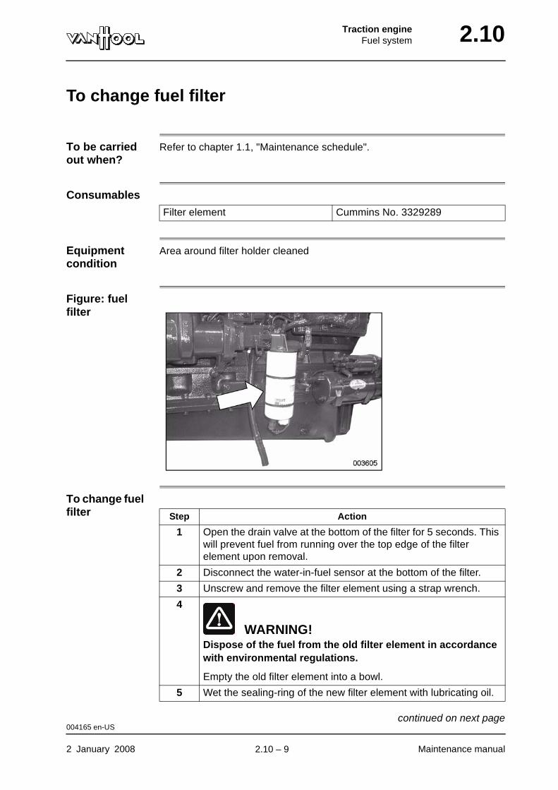
To change fuel filter
To be carried out when?
Refer to chapter 1.1, "Maintenance schedule".
Consumables
Equipment condition
Area around filter holder cleaned
Figure: fuel filter
To change fuel filter
Filter element Cummins No. 3329289
Step Action
1 Open the drain valve at the bottom of the filter for 5 seconds. This will prevent fuel from running over the top edge of the filter element upon removal.
2 Disconnect the water-in-fuel sensor at the bottom of the filter.
3 Unscrew and remove the filter element using a strap wrench.
4
WARNING!Dispose of the fuel from the old filter element in accordance with environmental regulations.
Empty the old filter element into a bowl.
5 Wet the sealing-ring of the new filter element with lubricating oil.
004165 en-US
2 January 2008 Maintenance manual
continued on next page.
2.10 – 9
2.10 Traction engineFuel system
6 Fill the new filter element with clean fuel.
7 Screw the new filter in place. Follow the instructions from the filter manufacturer.
8 Reconnect the "water-in-fuel" sensor.
9 Start the engine and check for leaks.
Step Action
004165 en-US
Maintenance manual 2 January 2008
.
2.10 – 10
Traction engineAir intake system 2.22
Chapter 22: Air intake system
Overview
Introduction This chapter deals with the air intake system.
Number of pages
12
Chapter publi-cation date
2 January 2008
Contents
Topic See page
To check air filter condition 2.22-2
To check air-filter service indicator 2.22-3
To check air-filter dust evacuation valve 2.22-5
To change air-filter element 2.22-6
To clean exterior of charge-air cooler 2.22-8
Technical data: air intake system 2.22-10
Special tools: air intake system 2.22-11
2 January 2008 Maintenance manual
.
2.22 – 1
2.22 Traction engineAir intake system
To check air filter condition
To be carried out when?
Before commencing daily service.
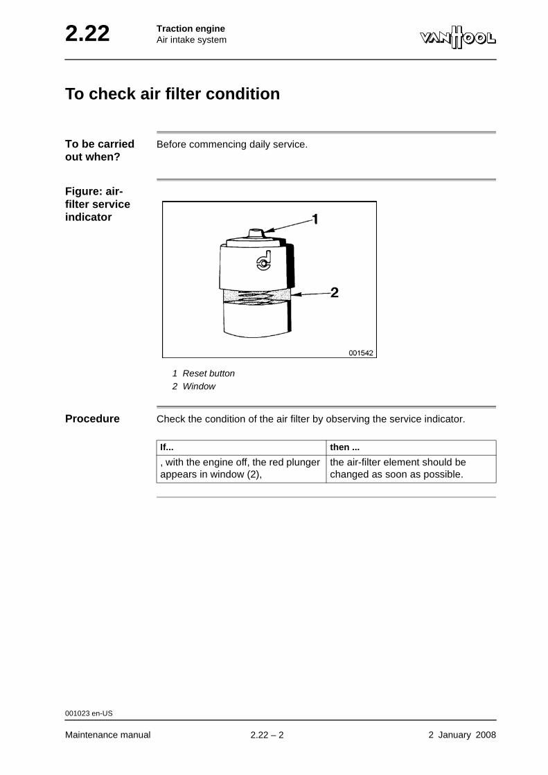
Figure: air-filter service indicator
1 Reset button2 Window
Procedure Check the condition of the air filter by observing the service indicator.
If... then ...
, with the engine off, the red plunger appears in window (2),
the air-filter element should be changed as soon as possible.
001023 en-US
Maintenance manual 2 January 2008
.
2.22 – 2
Traction engineAir intake system 2.22
To check air-filter service indicator
To be carried out when?
Refer to chapter 1.1, "Maintenance schedule".
Checking values
Refer to "Technical data" at the end of this chapter.
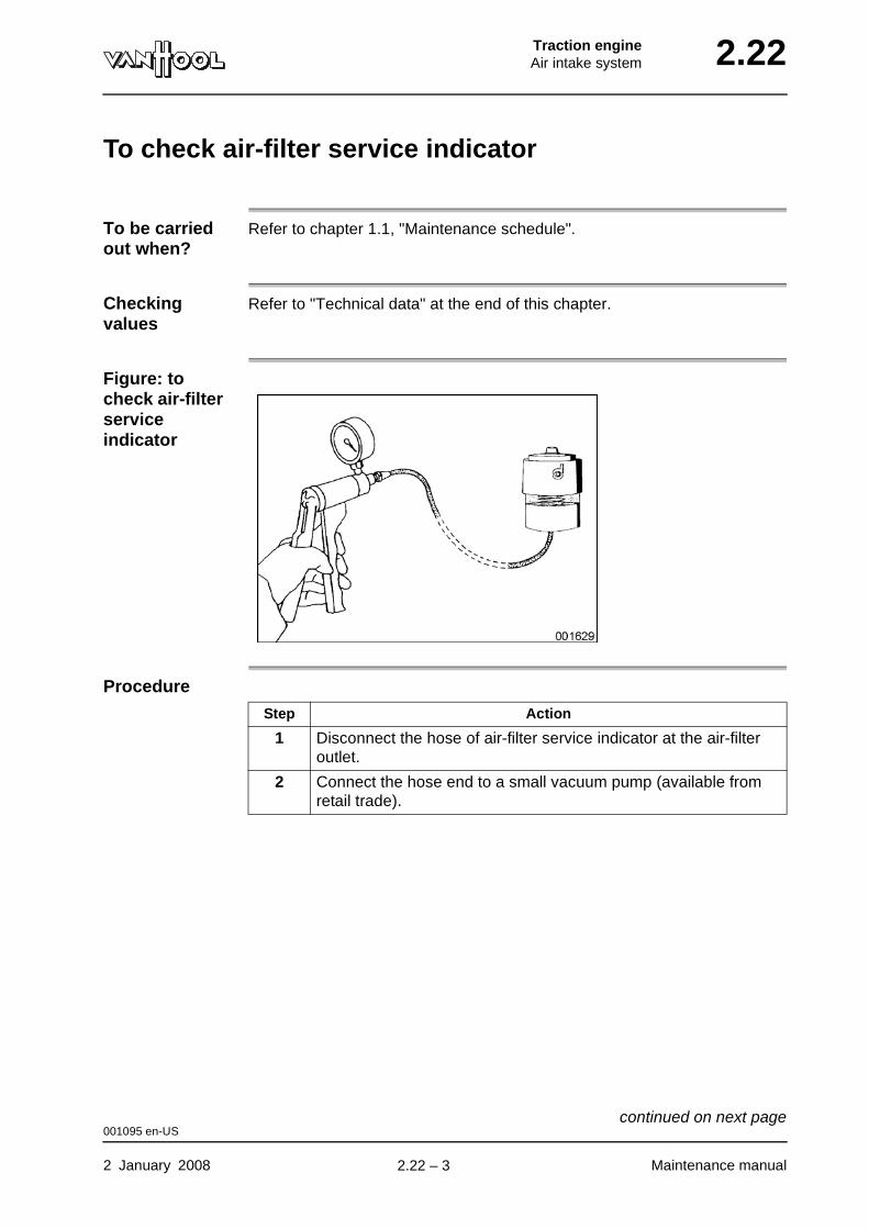
Figure: to check air-filter service indicator
Procedure
Step Action
1 Disconnect the hose of air-filter service indicator at the air-filter outlet.
2 Connect the hose end to a small vacuum pump (available from retail trade).
001095 en-US
2 January 2008 Maintenance manual
continued on next page.
2.22 – 3
2.22 Traction engineAir intake system
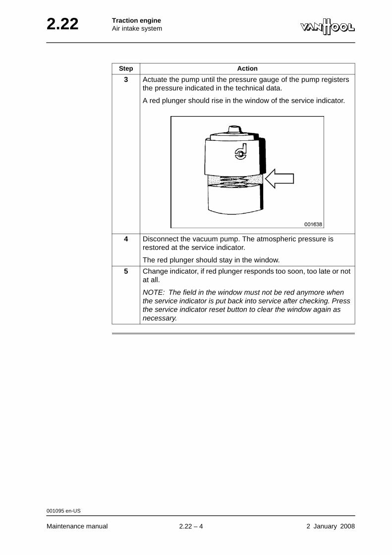
3 Actuate the pump until the pressure gauge of the pump registers the pressure indicated in the technical data.
A red plunger should rise in the window of the service indicator.
4 Disconnect the vacuum pump. The atmospheric pressure is restored at the service indicator.
The red plunger should stay in the window.
5 Change indicator, if red plunger responds too soon, too late or not at all.
NOTE: The field in the window must not be red anymore when the service indicator is put back into service after checking. Press the service indicator reset button to clear the window again as necessary.
Step Action
001095 en-US
Maintenance manual 2 January 2008
.
2.22 – 4
Traction engineAir intake system 2.22
To check air-filter dust evacuation valve
To be carried out when?
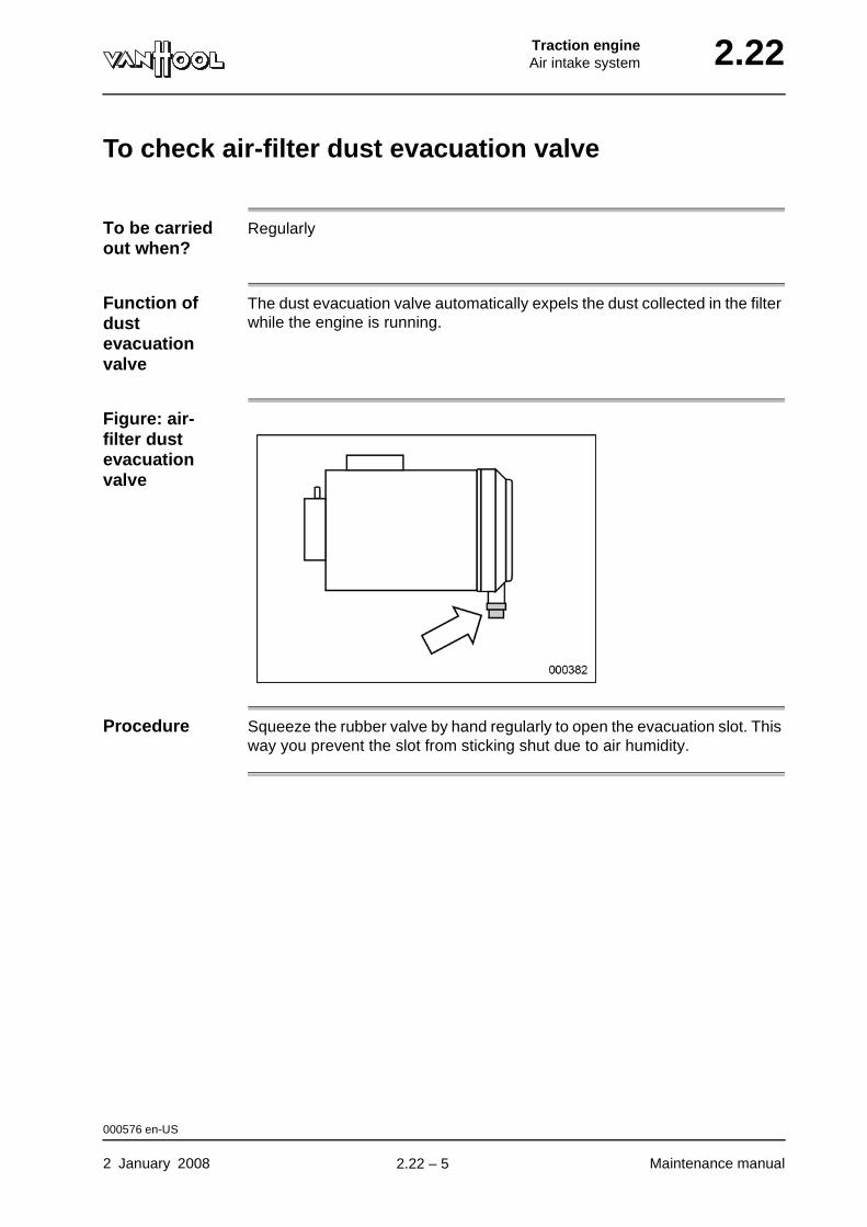
Regularly
Function of dust evacuation valve
The dust evacuation valve automatically expels the dust collected in the filter while the engine is running.
Figure: air-filter dust evacuation valve
Procedure Squeeze the rubber valve by hand regularly to open the evacuation slot. This way you prevent the slot from sticking shut due to air humidity.
000576 en-US
2 January 2008 Maintenance manual
.
2.22 – 5
2.22 Traction engineAir intake system
To change air-filter element
To be carried out when?
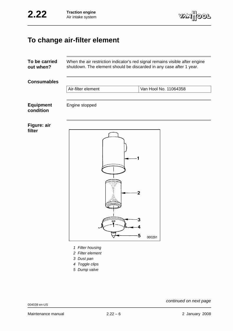
When the air restriction indicator's red signal remains visible after engine shutdown. The element should be discarded in any case after 1 year.
Consumables
Equipment condition
Engine stopped
Figure: air filter
1 Filter housing2 Filter element3 Dust pan4 Toggle clips5 Dump valve
Air-filter element Van Hool No. 11064358
004039 en-US
Maintenance manual 2 January 2008
continued on next page.
2.22 – 6
Traction engineAir intake system 2.22
Procedure
Step Action
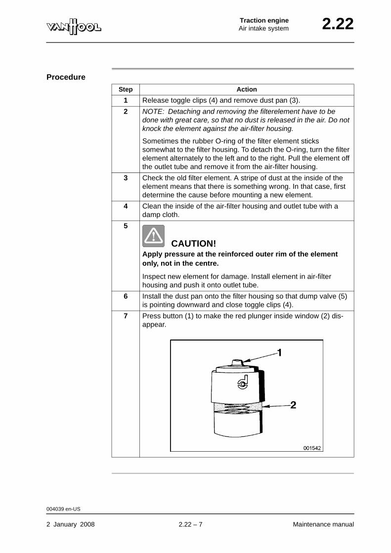
1 Release toggle clips (4) and remove dust pan (3).
2 NOTE: Detaching and removing the filterelement have to be done with great care, so that no dust is released in the air. Do not knock the element against the air-filter housing.
Sometimes the rubber O-ring of the filter element sticks somewhat to the filter housing. To detach the O-ring, turn the filter element alternately to the left and to the right. Pull the element off the outlet tube and remove it from the air-filter housing.
3 Check the old filter element. A stripe of dust at the inside of the element means that there is something wrong. In that case, first determine the cause before mounting a new element.
4 Clean the inside of the air-filter housing and outlet tube with a damp cloth.
5
CAUTION!Apply pressure at the reinforced outer rim of the element only, not in the centre.
Inspect new element for damage. Install element in air-filter housing and push it onto outlet tube.
6 Install the dust pan onto the filter housing so that dump valve (5) is pointing downward and close toggle clips (4).
7 Press button (1) to make the red plunger inside window (2) dis-appear.
004039 en-US
2 January 2008 Maintenance manual
.
2.22 – 7
2.22 Traction engineAir intake system
To clean exterior of charge-air cooler
To be carried out when?
Refer to chapter 1.1, "Maintenance schedule".
Cleaning product
Detergent P3-Grato 12 by Henkel, or similar product
Special tools
WARNING!Wear a dust mask, when cleaning with compressed air.
Nature of dirt
To use P3-Grato 12
Mix a quantity of P3-Grato 12 with a similar volume of water. Follow the instructions on the packaging.
NOTE: According to its manufacturer this detergent contains neither cor-rosive nor toxic agents.
Procedure
Cleaning tool Van Hool No.10527208
Nature of dirt Cleaning medium
Dry dust or sand Compressed air (approximately 115 psi)
Tenacious dirt Water + detergent.
NOTE: Van Hool recommend the use of P3-Grato 12 by Henkel.
Step Action
1 Carry out steps 1 up to and including 5, as mentioned in chapter 2.34 "To clean exterior of radiator".
2 Insert T-headed cleaning tool (with holes towards charge-air cooler, this means to front of vehicle) into gap between radiator and charge-air cooler.
000701 en-US
Maintenance manual 2 January 2008
continued on next page.
2.22 – 8
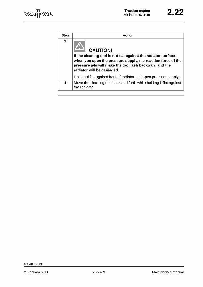
Traction engineAir intake system 2.22
3
CAUTION!If the cleaning tool is not flat against the radiator surface when you open the pressure supply, the reaction force of the pressure jets will make the tool lash backward and the radiator will be damaged.
Hold tool flat against front of radiator and open pressure supply.
4 Move the cleaning tool back and forth while holding it flat against the radiator.
Step Action
000701 en-US
2 January 2008 Maintenance manual
.
2.22 – 9

2.22 Traction engineAir intake system
Technical data: air intake system
Air-filter service indicator
Preset restriction limit 25 in H2O
001100 en-US
Maintenance manual 2 January 2008
.
2.22 – 10
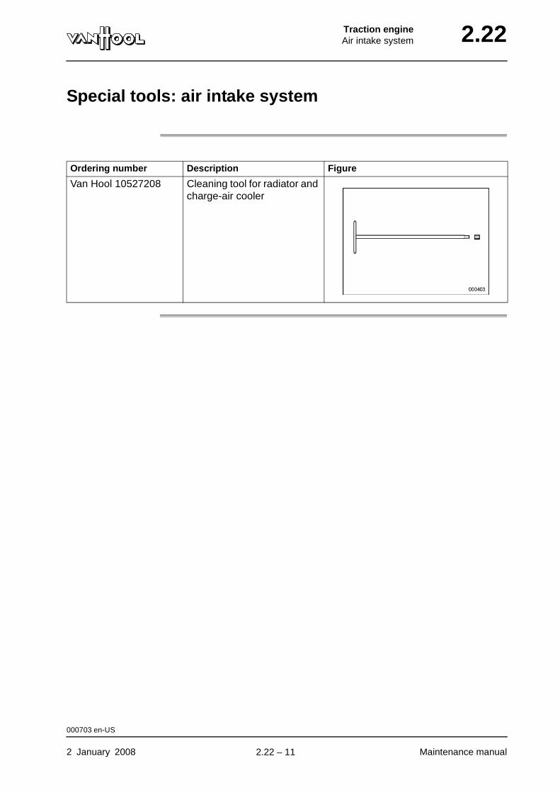
Traction engineAir intake system 2.22
Special tools: air intake system
Ordering number Description Figure
Van Hool 10527208 Cleaning tool for radiator and charge-air cooler
000703 en-US
2 January 2008 Maintenance manual
.
2.22 – 11

2.22 Traction engineAir intake system
This page has been intentionally left blank.
000703 en-US
Maintenance manual 2 January 20082.22 – 12

Traction engineExhaust system 2.30
Chapter 30: Exhaust system
Overview
Number of pages
14
Chapter publi-cation date
2 January 2008
Contents
Topic See page
Exhaust aftertreatment system: principle 2.30-2
Exhaust aftertreatment system: to regenerate particulate filter (DPF)
2.30-4
Exhaust aftertreatment system: to change particulate filter (DPF)
2.30-8
Technical data exhaust system 2.30-13
2 January 2008 Maintenance manual
.
2.30 – 1

2.30 Traction engineExhaust system
Exhaust aftertreatment system: principle
Type The vehicle has been equiped with a “Continuously Regenerating Trap” exhaust aftertreatment system.
Parts The exhaust aftertreatment system consists of an oxidation catalyst (DOC) and a particulate filter (DPF). The device has been equiped with three tem-perature sensors and a differential pressure sensor checking its operation.
Figure: exhaust after-treatment system (example)
1 Temperature sensor2 Temperature sensor3 Temperature sensor4 Outlet module5 Particulate filter module6 Differential pressure sensor7 Catalyst module8 Inlet module
006940 en-US
Maintenance manual 2 January 2008
continued on next page.
2.30 – 2
Traction engineExhaust system 2.30
Oxidation catalyst (DOC)
Consists of a ceramic structure on which a noble metal has been vaporized. The noble metal serves as a catalyst for the hydrocarbons (CH) and the carbon monoxide (CO). Together with the oxygen in the excess air, the noble metal starts up a chemical reaction. Hence the name oxidation catalyst.
In the oxidation catalyst, the following transformations take place,
• CH4 + 2O2 --- CO2 + 2H2O
• 2CO + O2 --- 2CO2
• 2NO + O2 --- 2NO2
Particulate filter (DPF)
Most of the soot particles containing carbon and ash are captured in the par-ticulate filter.
Wat happens with the carbon?
Once the self-cleaning temperature is reached (approx. 570°F), the carbon reacts with the nitrogen dioxide and burns to become carbon dioxide. This process is called regeneration.
• 2NO 2 + C --- 2NO + CO2
Wat happens with the ash?
The ash particulates can only be removed by cleaning the filter. To this end, the manufacturere of the exhaust aftertreatment system works with an exchange system. The contaminated filter module is exchanged for a cleaned unit at a certain cost.
006940 en-US
2 January 2008 Maintenance manual
.
2.30 – 3
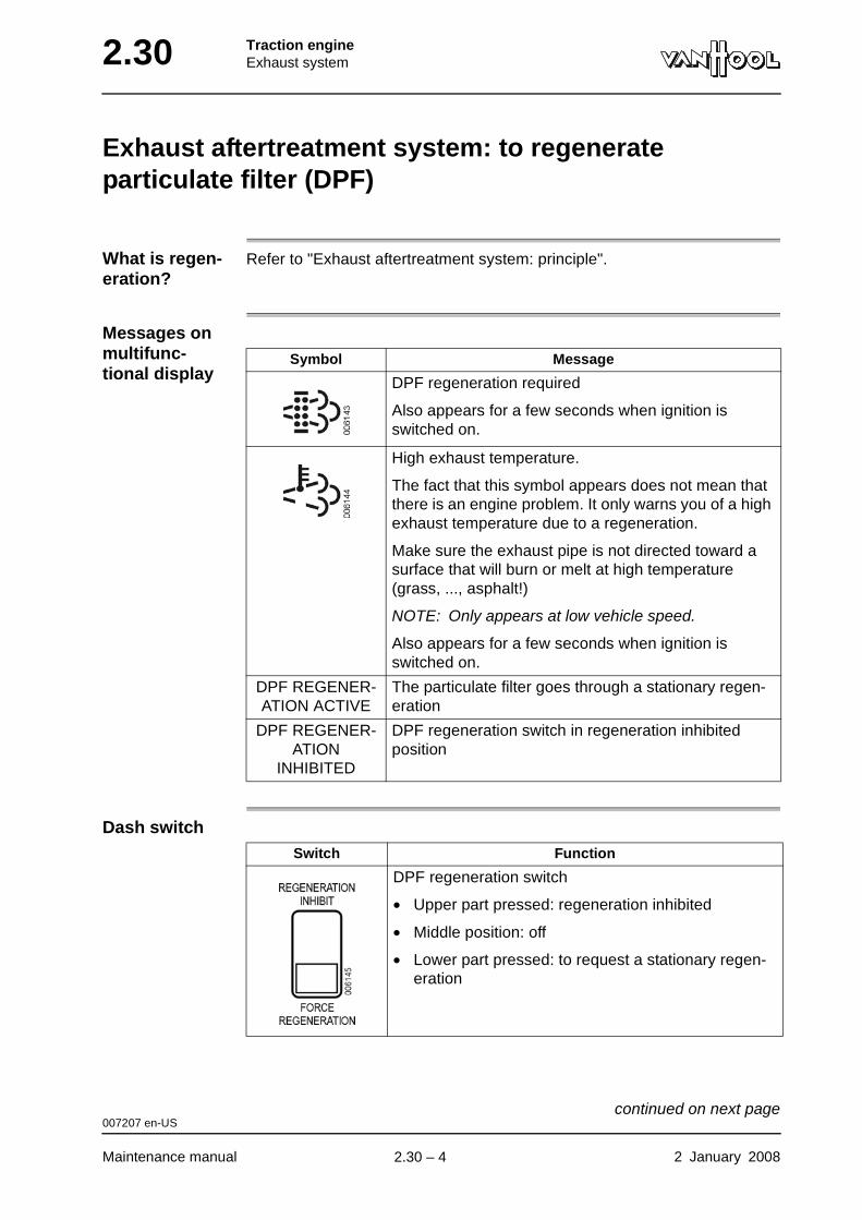
2.30 Traction engineExhaust system
Exhaust aftertreatment system: to regenerate particulate filter (DPF)
What is regen-eration?
Refer to "Exhaust aftertreatment system: principle".
Messages on multifunc-tional display
Dash switch
Symbol Message
DPF regeneration required
Also appears for a few seconds when ignition is switched on.
High exhaust temperature.
The fact that this symbol appears does not mean that there is an engine problem. It only warns you of a high exhaust temperature due to a regeneration.
Make sure the exhaust pipe is not directed toward a surface that will burn or melt at high temperature (grass, ..., asphalt!)
NOTE: Only appears at low vehicle speed.
Also appears for a few seconds when ignition is switched on.
DPF REGENER-ATION ACTIVE
The particulate filter goes through a stationary regen-eration
DPF REGENER-ATION
INHIBITED
DPF regeneration switch in regeneration inhibited position
Switch Function
DPF regeneration switch
• Upper part pressed: regeneration inhibited
• Middle position: off
• Lower part pressed: to request a stationary regen-eration
007207 en-US
Maintenance manual 2 January 2008
continued on next page.
2.30 – 4
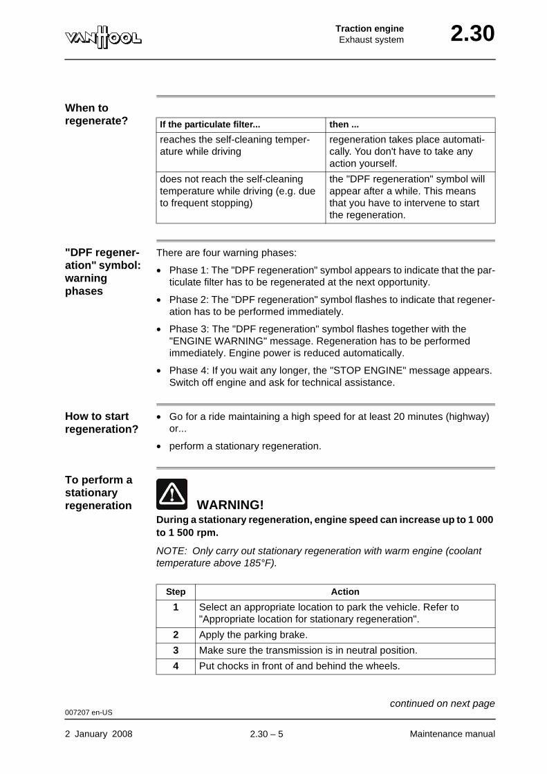
Traction engineExhaust system 2.30
When to regenerate?
"DPF regener-ation" symbol: warning phases
There are four warning phases:
• Phase 1: The "DPF regeneration" symbol appears to indicate that the par-ticulate filter has to be regenerated at the next opportunity.
• Phase 2: The "DPF regeneration" symbol flashes to indicate that regener-ation has to be performed immediately.
• Phase 3: The "DPF regeneration" symbol flashes together with the "ENGINE WARNING" message. Regeneration has to be performed immediately. Engine power is reduced automatically.
• Phase 4: If you wait any longer, the "STOP ENGINE" message appears. Switch off engine and ask for technical assistance.
How to start regeneration?
• Go for a ride maintaining a high speed for at least 20 minutes (highway) or...
• perform a stationary regeneration.
To perform a stationary regeneration WARNING!
During a stationary regeneration, engine speed can increase up to 1 000 to 1 500 rpm.
NOTE: Only carry out stationary regeneration with warm engine (coolant temperature above 185°F).
If the particulate filter... then ...
reaches the self-cleaning temper-ature while driving
regeneration takes place automati-cally. You don't have to take any action yourself.
does not reach the self-cleaning temperature while driving (e.g. due to frequent stopping)
the "DPF regeneration" symbol will appear after a while. This means that you have to intervene to start the regeneration.
Step Action
1 Select an appropriate location to park the vehicle. Refer to "Appropriate location for stationary regeneration".
2 Apply the parking brake.
3 Make sure the transmission is in neutral position.
4 Put chocks in front of and behind the wheels.
007207 en-US
2 January 2008 Maintenance manual
continued on next page.
2.30 – 5
2.30 Traction engineExhaust system
To inhibit/interrupt regeneration
If regeneration causes hazardous situations (e.g. at a stop), you can inhibit/interrupt the regeneration process. To this end, press the upper part of the DPF regeneration switch.
Appropriate location for stationary regeneration
• Surface that will not start to burn or to melt under high temperatures (such as clean concrete; no grass or asphalt!);
• Away from anything that can burn, melt or explode;
• Not near gas or vapors that can ignite, explode or contribute to a fire (such as LPG, diesel vapors, ...).
Safety area around exhaust
• If bystanders can access the area, set up barriers at least 5 ft away from the exhaust.
5 Set up a safety area around the exhaust. Refer to "Safety area around exhaust".
6 Shut off the climate-control system.
7 Carry out the actions below within a 35 seconds time limit:
• Release the parking brake and reapply it.
• Put transmission from N to D and back to N.
• Press the lower part of the DPF regeneration switch during 5 to 10 seconds.
The stationary regeneration is initiated. The engine speed increases and the "DPF-regeneration" symbol disappears.
8
WARNING!If an unsafe situation occurs, stop the regeneration process immediately by pushing the brake pedal or by switching off the engine. Regeneration is also stopped if you put the "DPF regeneration" switch in the "INHIBIT REGEN" position.
Observe the vehicle and its immediate surroundings during regeneration.
The regeneration process takes 20 to 40 minutes. The regener-ation has succeeded if the engine speed automatically returns to idling speed and if the "DPF regeneration" symbol does not reappear.
If the "DPF regeneration" symbol reappears, the regeneration process has failed. In that case, ask for technical assistance.
Step Action
007207 en-US
Maintenance manual 2 January 2008
continued on next page.
2.30 – 6
Traction engineExhaust system 2.30
• If regeneration takes place in a confined space, connect an exhaust gas evacuation system to the exhaust pipe. The evacuation system has to resist temperatures of at least 1500°F.
• Keep a fire extinguisher nearby.
007207 en-US
2 January 2008 Maintenance manual
.
2.30 – 7

2.30 Traction engineExhaust system
Exhaust aftertreatment system: to change particulate filter (DPF)
Application Vehicles with Cummins ISM07 engine
To be carried out when?
Refer to chapter 1.1, "Maintenance schedule".
Consumables
Tightening torques
Refer to "Technical data" at the end of this chapter.
Equipment condition
Exhaust aftertreatment device cold
WARNING!Handle the exhaust aftertreatment device with care. It contains fragile ceramic material.
WARNING!The material captured in the particulate filter may contain elevated con-centrations of metals, zinc and molybdenum, and possibly also polynu-clear aromatic hydrocarbons subject to regulation. This material should be handled and removed in accordance with local regulations.
WARNING!The exhaust aftertreatment device weighs more than 50 lbs (depending on the type up to 150 lbs). Use a lifting device for removing/installing.
Particulate filter module Cummins no. 4965244 NX
Gasket (2x) Cummins no. 3684079
007174 en-US
Maintenance manual 2 January 2008
continued on next page.
2.30 – 8
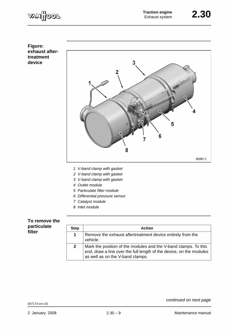
Traction engineExhaust system 2.30
Figure: exhaust after-treatment device
1 V-band clamp with gasket2 V-band clamp with gasket3 V-band clamp with gasket4 Outlet module5 Particulate filter module6 Differential pressure sensor7 Catalyst module8 Inlet module
To remove the particulate filter
Step Action
1 Remove the exhaust aftertreatment device entirely from the vehicle.
2 Mark the position of the modules and the V-band clamps. To this end, draw a line over the full length of the device, on the modules as well as on the V-band clamps.
007174 en-US
2 January 2008 Maintenance manual
continued on next page.
2.30 – 9
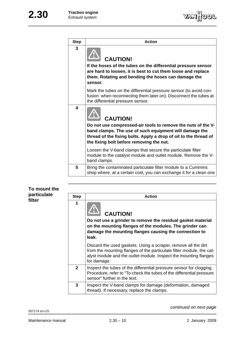
2.30 Traction engineExhaust system
To mount the particulate filter
3
CAUTION!If the hoses of the tubes on the differential pressure sensor are hard to loosen, it is best to cut them loose and replace them. Rotating and bending the hoses can damage the sensor.
Mark the tubes on the differential pressure sensor (to avoid con-fusion when reconnecting them later on). Disconnect the tubes at the differential pressure sensor.
4
CAUTION!Do not use compressed-air tools to remove the nuts of the V-band clamps. The use of such equipment will damage the thread of the fixing bolts. Apply a drop of oil to the thread of the fixing bolt before removing the nut.
Loosen the V-band clamps that secure the particulate filter module to the catalyst module and outlet module. Remove the V-band clamps.
5 Bring the contaminated particulate filter module to a Cummins shop where, at a certain cost, you can exchange it for a clean one
Step Action
Step Action
1
CAUTION!Do not use a grinder to remove the residual gasket material on the mounting flanges of the modules. The grinder can damage the mounting flanges causing the connection to leak.
Discard the used gaskets. Using a scraper, remove all the dirt from the mounting flanges of the particulate filter module, the cat-alyst module and the outlet module. Inspect the mounting flanges for damage.
2 Inspect the tubes of the differential pressure sensor for clogging. Procedure, refer to "To check the tubes of the differential pressure sensor" further in the text.
3 Inspect the V-band clamps for damage (deformation, damaged thread). If necessary, replace the clamps.
007174 en-US
Maintenance manual 2 January 2008
continued on next page.
2.30 – 10
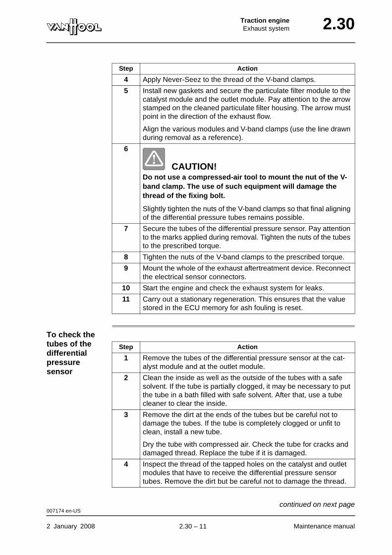
Traction engineExhaust system 2.30
To check the tubes of the differential pressure sensor
4 Apply Never-Seez to the thread of the V-band clamps.
5 Install new gaskets and secure the particulate filter module to the catalyst module and the outlet module. Pay attention to the arrow stamped on the cleaned particulate filter housing. The arrow must point in the direction of the exhaust flow.
Align the various modules and V-band clamps (use the line drawn during removal as a reference).
6
CAUTION!Do not use a compressed-air tool to mount the nut of the V-band clamp. The use of such equipment will damage the thread of the fixing bolt.
Slightly tighten the nuts of the V-band clamps so that final aligning of the differential pressure tubes remains possible.
7 Secure the tubes of the differential pressure sensor. Pay attention to the marks applied during removal. Tighten the nuts of the tubes to the prescribed torque.
8 Tighten the nuts of the V-band clamps to the prescribed torque.
9 Mount the whole of the exhaust aftertreatment device. Reconnect the electrical sensor connectors.
10 Start the engine and check the exhaust system for leaks.
11 Carry out a stationary regeneration. This ensures that the value stored in the ECU memory for ash fouling is reset.
Step Action
Step Action
1 Remove the tubes of the differential pressure sensor at the cat-alyst module and at the outlet module.
2 Clean the inside as well as the outside of the tubes with a safe solvent. If the tube is partially clogged, it may be necessary to put the tube in a bath filled with safe solvent. After that, use a tube cleaner to clear the inside.
3 Remove the dirt at the ends of the tubes but be careful not to damage the tubes. If the tube is completely clogged or unfit to clean, install a new tube.
Dry the tube with compressed air. Check the tube for cracks and damaged thread. Replace the tube if it is damaged.
4 Inspect the thread of the tapped holes on the catalyst and outlet modules that have to receive the differential pressure sensor tubes. Remove the dirt but be careful not to damage the thread.
007174 en-US
2 January 2008 Maintenance manual
continued on next page.
2.30 – 11
2.30 Traction engineExhaust system
007174 en-US
Maintenance manual 2 January 2008
.
2.30 – 12
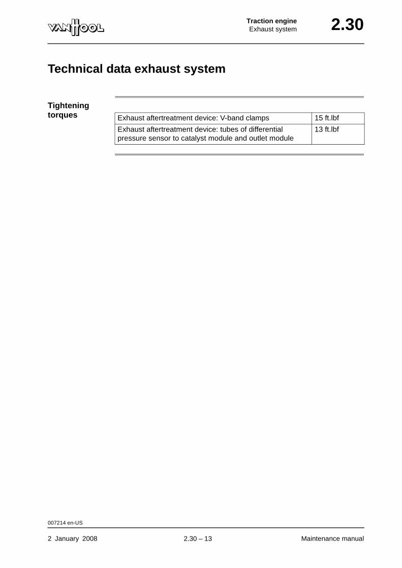
Traction engineExhaust system 2.30
Technical data exhaust system
Tightening torques Exhaust aftertreatment device: V-band clamps 15 ft.lbf
Exhaust aftertreatment device: tubes of differential pressure sensor to catalyst module and outlet module
13 ft.lbf
007214 en-US
2 January 2008 Maintenance manual
.
2.30 – 13
2.30 Traction engineExhaust system
This page has been intentionally left blank.
007214 en-US
Maintenance manual 2 January 20082.30 – 14
Traction engineCooling system 2.34
Chapter 34: Cooling system
Overview
Introduction This chapter deals with the cooling system.
Number of pages
30
Chapter publi-cation date
14 November 2008
Contents
Topic See page
Safety instructions relating to cooling system 2.34-2
Coolant for Cummins engine 2.34-4
To check coolant level 2.34-6
To drain engine cooling circuit 2.34-8
To fill and bleed engine cooling circuit 2.34-10
To check DCA4-concentration 2.34-11
To change DCA4 element 2.34-12
To check/clean radiator compartment mesh screen 2.34-14
To clean radiator exterior 2.34-15
To check condition of water hoses 2.34-17
Hose clamp types 2.34-18
To check hose clamps tightening torque 2.34-19
Fan clutch types 2.34-20
Fan clutch operation 2.34-21
To determine remaining service life span of fan clutch 2.34-24
Technical data: cooling system 2.34-27
Special tools: cooling system 2.34-29
14 November 2008 Maintenance manual
.
2.34 – 1
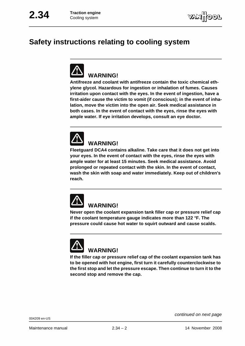
2.34 Traction engineCooling system
Safety instructions relating to cooling system
WARNING!Antifreeze and coolant with antifreeze contain the toxic chemical eth-ylene glycol. Hazardous for ingestion or inhalation of fumes. Causes irritation upon contact with the eyes. In the event of ingestion, have a first-aider cause the victim to vomit (if conscious); in the event of inha-lation, move the victim into the open air. Seek medical assistance in both cases. In the event of contact with the eyes, rinse the eyes with ample water. If eye irritation develops, consult an eye doctor.
WARNING!Fleetguard DCA4 contains alkaline. Take care that it does not get into your eyes. In the event of contact with the eyes, rinse the eyes with ample water for at least 15 minutes. Seek medical assistance. Avoid prolonged or repeated contact with the skin. In the event of contact, wash the skin with soap and water immediately. Keep out of children's reach.
WARNING!Never open the coolant expansion tank filler cap or pressure relief cap if the coolant temperature gauge indicates more than 122 °F. The pressure could cause hot water to squirt outward and cause scalds.
WARNING!If the filler cap or pressure relief cap of the coolant expansion tank has to be opened with hot engine, first turn it carefully counterclockwise to the first stop and let the pressure escape. Then continue to turn it to the second stop and remove the cap.
004209 en-US
Maintenance manual 14 November 2008
continued on next page.
2.34 – 2
Traction engineCooling system 2.34
CAUTION!Never add cold coolant, when the engine is hot. The sudden cooling could cause parts of the engine block to crack.
004209 en-US
14 November 2008 Maintenance manual
.
2.34 – 3
2.34 Traction engineCooling system
Coolant for Cummins engine
WARNING!Coolant contains the toxic chemical ethylene glycol. Hazardous for ingestion or inhalation of fumes. Causes irritation upon contact with the eyes. In the event of ingestion, have a first-aider cause the victim to vomit (if conscious); in the event of inhalation, move the victim into the open air. Seek medical assistance in both cases. In the event of contact with the eyes, rinse the eyes with ample water. If eye irritation develops, consult an eye doctor.
Which coolant to use?
Refer to chapter 1.1, "Fluids and lubricants".
Antifreeze concentration
NOTE: Fresh fully formulated coolant contains 50% antifreeze. This concen-tration protects against frost to approximately -25 °F. If you expect exterior temperature to drop below -25 °F, increase antifreeze concentration according to the instructions given by Cummins. Antifreeze concentrations higher than 60% are not allowed.
To protect the system against corrosion and deposits, at least 40% of the coolant volume has to consist of antifreeze, both in winter and summer. This concentration protects against frost up to -12 °F.
How to measure antifreeze con-centration?
To measure the concentration, use a refractometer (Fleetguard No. C2800).
Fleetguard DCA4
Fleetguard DCA4 is a coolant additive that provides added protection for the engine and metal parts of the cooling and heating system.
004210 en-US
Maintenance manual 14 November 2008
continued on next page.
2.34 – 4
Traction engineCooling system 2.34
WARNING!Fleetguard DCA4 contains alkaline. Take care that it does not get into your eyes. In the event of contact with the eyes, rinse the eyes with ample water for at least 15 minutes. Seek medical assistance. Avoid prolonged or repeated contact with the skin. In the event of contact, wash the skin with soap and water immediately. Keep out of children's reach.
DCA4 concen-tration
The effectiveness of the Fleetguard protection system depends on the correct quantity of DCA4 in the coolant system. Regularly check the concen-tration level using the Fleetguard CC2626 test kit.
When to change coolant?
• Because, when in use, antifreeze loses its protective qualities over time, you need to check the coolant annually to determine if it needs to be changed. Contact Cummins for further information.
• All coolant (engine circuit and interior heating) must also be changed, after a new engine, radiator or water-cooled retarder has been installed. The reason is that only fresh coolant contains sufficient additives to create an effective basic protective layer on new metal parts.
To dispose of coolant
Antifreeze, DCA4 or coolant must not be disposed of through the sewer.
004210 en-US
14 November 2008 Maintenance manual
.
2.34 – 5
2.34 Traction engineCooling system
To check coolant level
To be carried out when?
Before commencing daily service.
Equipment conditions
Cold engine
WARNING!Never open the filler cap if the coolant thermometer indicates more than 122 °F. The pressure could cause hot water to squirt outward and cause scalds.
WARNING!If the filler cap has to be opened with a warm engine, first carefully turn it counterclockwise to the first stop and let the pressure escape. Then turn to the second stop and remove the cap.
CAUTION!Never poor cold coolant in the expansion tank when the engine is hot. The sudden cooling could cause parts of the engine block to crack.
004976 en-US
Maintenance manual 14 November 2008
continued on next page.
2.34 – 6
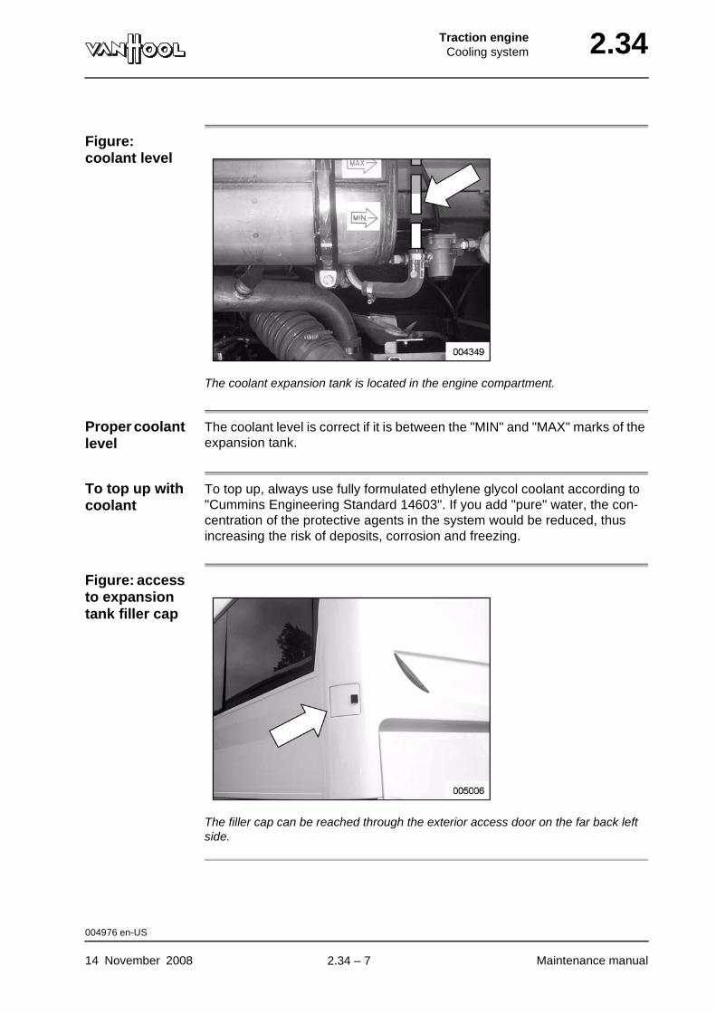
Traction engineCooling system 2.34
Figure: coolant level
The coolant expansion tank is located in the engine compartment.
Proper coolant level
The coolant level is correct if it is between the "MIN" and "MAX" marks of the expansion tank.
To top up with coolant
To top up, always use fully formulated ethylene glycol coolant according to "Cummins Engineering Standard 14603". If you add "pure" water, the con-centration of the protective agents in the system would be reduced, thus increasing the risk of deposits, corrosion and freezing.
Figure: access to expansion tank filler cap
The filler cap can be reached through the exterior access door on the far back left side.
004976 en-US
14 November 2008 Maintenance manual
.
2.34 – 7
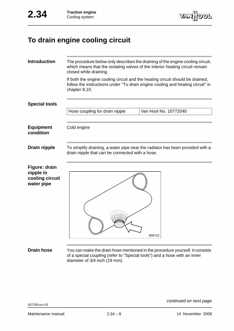
2.34 Traction engineCooling system
To drain engine cooling circuit
Introduction The procedure below only describes the draining of the engine cooling circuit, which means that the isolating valves of the interior heating circuit remain closed while draining.
If both the engine cooling circuit and the heating circuit should be drained, follow the instructions under "To drain engine cooling and heating circuit" in chapter 8.10.
Special tools
Equipment condition
Cold engine
Drain nipple To simplify draining, a water pipe near the radiator has been provided with a drain nipple that can be connected with a hose.
Figure: drain nipple in cooling circuit water pipe
Drain hose You can make the drain hose mentioned in the procedure yourself. It consists of a special coupling (refer to "Special tools") and a hose with an inner diameter of 3/4 inch (19 mm).
Hose coupling for drain nipple Van Hool No. 10772040
007299 en-US
Maintenance manual 14 November 2008
continued on next page.
2.34 – 8
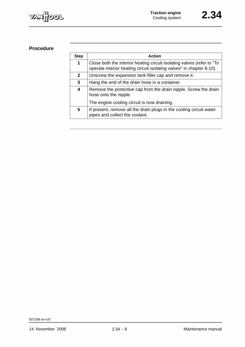
Traction engineCooling system 2.34
Procedure
Step Action
1 Close both the interior heating circuit isolating valves (refer to "To operate interior heating circuit isolating valves" in chapter 8.10).
2 Unscrew the expansion tank filler cap and remove it.
3 Hang the end of the drain hose in a container.
4 Remove the protective cap from the drain nipple. Screw the drain hose onto the nipple.
The engine cooling circuit is now draining.
5 If present, remove all the drain plugs in the cooling circuit water pipes and collect the coolant.
007299 en-US
14 November 2008 Maintenance manual
.
2.34 – 9
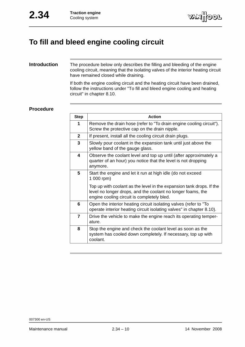
2.34 Traction engineCooling system
To fill and bleed engine cooling circuit
Introduction The procedure below only describes the filling and bleeding of the engine cooling circuit, meaning that the isolating valves of the interior heating circuit have remained closed while draining.
If both the engine cooling circuit and the heating circuit have been drained, follow the instructions under "To fill and bleed engine cooling and heating circuit" in chapter 8.10.
Procedure
Step Action
1 Remove the drain hose (refer to "To drain engine cooling circuit"). Screw the protective cap on the drain nipple.
2 If present, install all the cooling circuit drain plugs.
3 Slowly pour coolant in the expansion tank until just above the yellow band of the gauge glass.
4 Observe the coolant level and top up until (after approximately a quarter of an hour) you notice that the level is not dropping anymore.
5 Start the engine and let it run at high idle (do not exceed 1 000 rpm)
Top up with coolant as the level in the expansion tank drops. If the level no longer drops, and the coolant no longer foams, the engine cooling circuit is completely bled.
6 Open the interior heating circuit isolating valves (refer to "To operate interior heating circuit isolating valves" in chapter 8.10).
7 Drive the vehicle to make the engine reach its operating temper-ature.
8 Stop the engine and check the coolant level as soon as the system has cooled down completely. If necessary, top up with coolant.
007300 en-US
Maintenance manual 14 November 2008
.
2.34 – 10
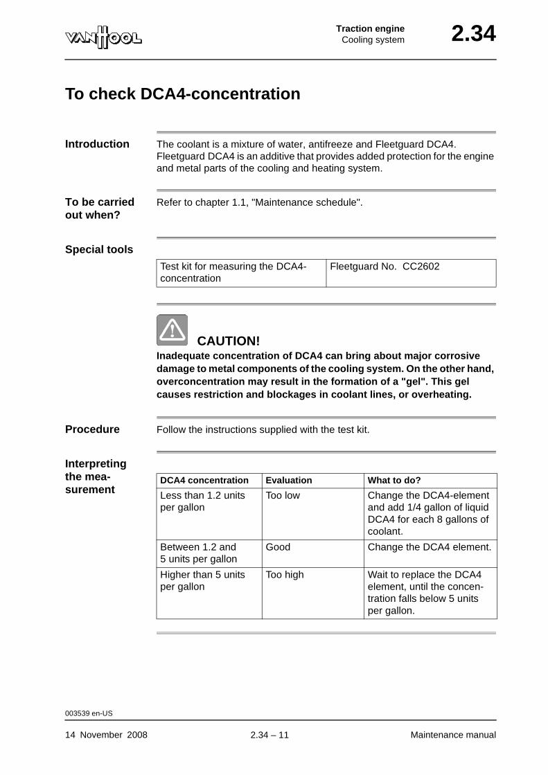
Traction engineCooling system 2.34
To check DCA4-concentration
Introduction The coolant is a mixture of water, antifreeze and Fleetguard DCA4. Fleetguard DCA4 is an additive that provides added protection for the engine and metal parts of the cooling and heating system.
To be carried out when?
Refer to chapter 1.1, "Maintenance schedule".
Special tools
CAUTION!Inadequate concentration of DCA4 can bring about major corrosive damage to metal components of the cooling system. On the other hand, overconcentration may result in the formation of a "gel". This gel causes restriction and blockages in coolant lines, or overheating.
Procedure Follow the instructions supplied with the test kit.
Interpreting the mea-surement
Test kit for measuring the DCA4-concentration
Fleetguard No. CC2602
DCA4 concentration Evaluation What to do?
Less than 1.2 units per gallon
Too low Change the DCA4-element and add 1/4 gallon of liquid DCA4 for each 8 gallons of coolant.
Between 1.2 and 5 units per gallon
Good Change the DCA4 element.
Higher than 5 units per gallon
Too high Wait to replace the DCA4 element, until the concen-tration falls below 5 units per gallon.
003539 en-US
14 November 2008 Maintenance manual
.
2.34 – 11
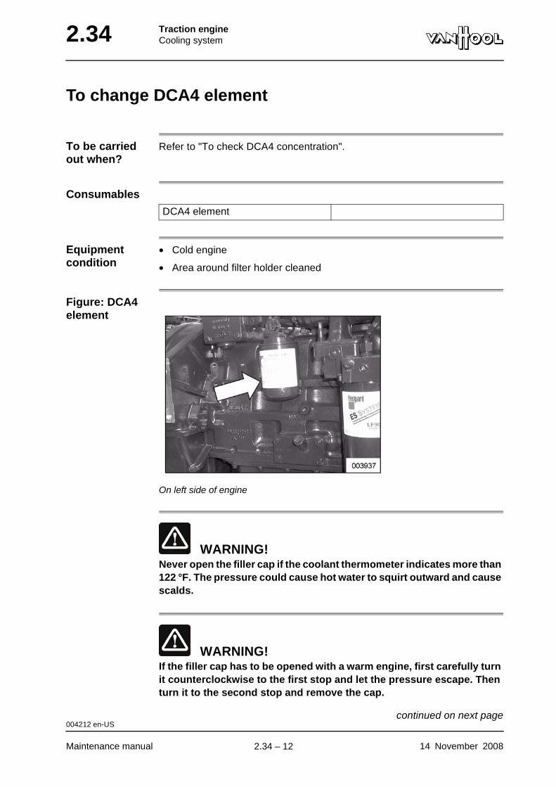
2.34 Traction engineCooling system
To change DCA4 element
To be carried out when?
Refer to "To check DCA4 concentration".
Consumables
Equipment condition
• Cold engine
• Area around filter holder cleaned
Figure: DCA4 element
On left side of engine
WARNING!Never open the filler cap if the coolant thermometer indicates more than 122 °F. The pressure could cause hot water to squirt outward and cause scalds.
WARNING!If the filler cap has to be opened with a warm engine, first carefully turn it counterclockwise to the first stop and let the pressure escape. Then turn it to the second stop and remove the cap.
DCA4 element
004212 en-US
Maintenance manual 14 November 2008
continued on next page.
2.34 – 12
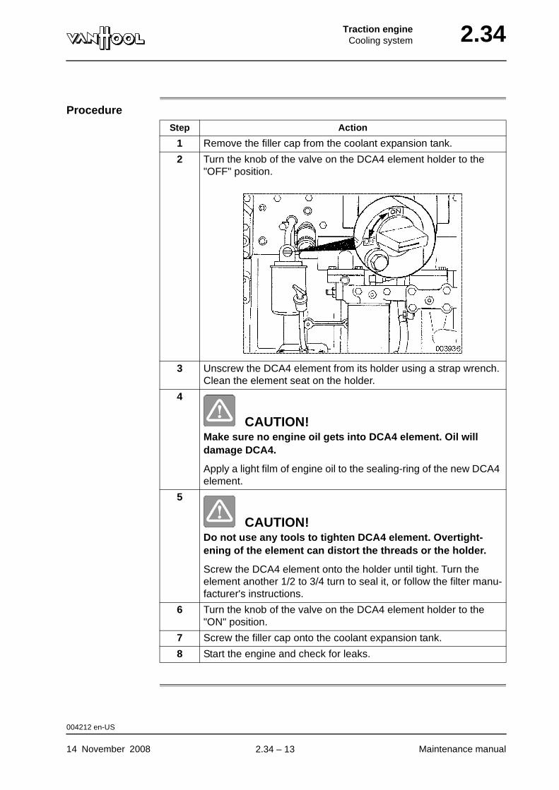
Traction engineCooling system 2.34
Procedure
Step Action
1 Remove the filler cap from the coolant expansion tank.
2 Turn the knob of the valve on the DCA4 element holder to the "OFF" position.
3 Unscrew the DCA4 element from its holder using a strap wrench. Clean the element seat on the holder.
4
CAUTION!Make sure no engine oil gets into DCA4 element. Oil will damage DCA4.
Apply a light film of engine oil to the sealing-ring of the new DCA4 element.
5
CAUTION!Do not use any tools to tighten DCA4 element. Overtight-ening of the element can distort the threads or the holder.
Screw the DCA4 element onto the holder until tight. Turn the element another 1/2 to 3/4 turn to seal it, or follow the filter manu-facturer's instructions.
6 Turn the knob of the valve on the DCA4 element holder to the "ON" position.
7 Screw the filler cap onto the coolant expansion tank.
8 Start the engine and check for leaks.
004212 en-US
14 November 2008 Maintenance manual
.
2.34 – 13
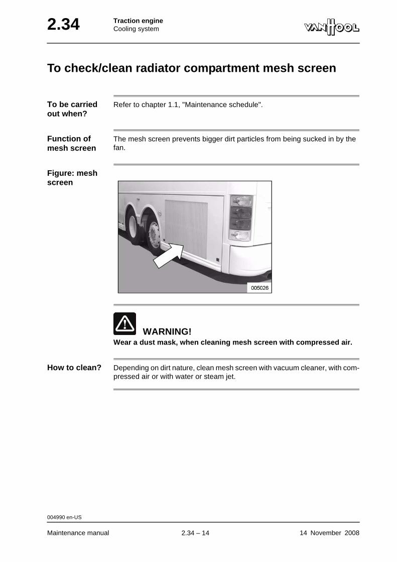
2.34 Traction engineCooling system
To check/clean radiator compartment mesh screen
To be carried out when?
Refer to chapter 1.1, "Maintenance schedule".
Function of mesh screen
The mesh screen prevents bigger dirt particles from being sucked in by the fan.
Figure: mesh screen
WARNING!Wear a dust mask, when cleaning mesh screen with compressed air.
How to clean? Depending on dirt nature, clean mesh screen with vacuum cleaner, with com-pressed air or with water or steam jet.
004990 en-US
Maintenance manual 14 November 2008
.
2.34 – 14
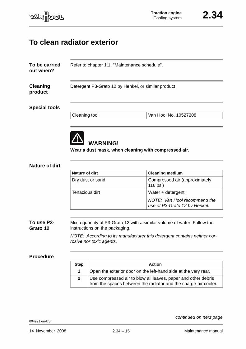
Traction engineCooling system 2.34
To clean radiator exterior
To be carried out when?
Refer to chapter 1.1, "Maintenance schedule".
Cleaning product
Detergent P3-Grato 12 by Henkel, or similar product
Special tools
WARNING!Wear a dust mask, when cleaning with compressed air.
Nature of dirt
To use P3-Grato 12
Mix a quantity of P3-Grato 12 with a similar volume of water. Follow the instructions on the packaging.
NOTE: According to its manufacturer this detergent contains neither cor-rosive nor toxic agents.
Procedure
Cleaning tool Van Hool No. 10527208
Nature of dirt Cleaning medium
Dry dust or sand Compressed air (approximately 116 psi)
Tenacious dirt Water + detergent
NOTE: Van Hool recommend the use of P3-Grato 12 by Henkel.
Step Action
1 Open the exterior door on the left-hand side at the very rear.
2 Use compressed air to blow all leaves, paper and other debris from the spaces between the radiator and the charge-air cooler.
004991 en-US
14 November 2008 Maintenance manual
continued on next page.
2.34 – 15
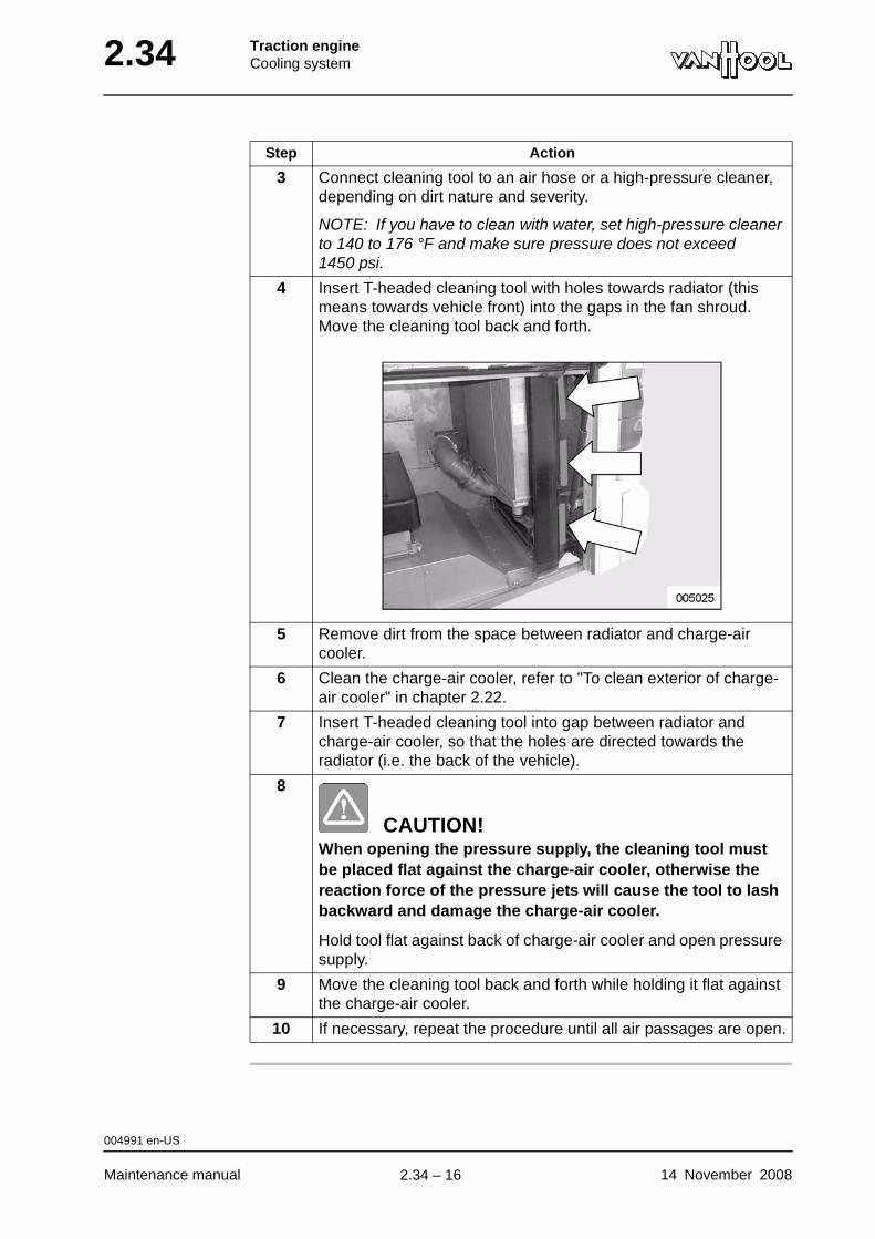
2.34 Traction engineCooling system
3 Connect cleaning tool to an air hose or a high-pressure cleaner, depending on dirt nature and severity.
NOTE: If you have to clean with water, set high-pressure cleaner to 140 to 176 °F and make sure pressure does not exceed 1450 psi.
4 Insert T-headed cleaning tool with holes towards radiator (this means towards vehicle front) into the gaps in the fan shroud. Move the cleaning tool back and forth.
5 Remove dirt from the space between radiator and charge-air cooler.
6 Clean the charge-air cooler, refer to "To clean exterior of charge-air cooler" in chapter 2.22.
7 Insert T-headed cleaning tool into gap between radiator and charge-air cooler, so that the holes are directed towards the radiator (i.e. the back of the vehicle).
8
CAUTION!When opening the pressure supply, the cleaning tool must be placed flat against the charge-air cooler, otherwise the reaction force of the pressure jets will cause the tool to lash backward and damage the charge-air cooler.
Hold tool flat against back of charge-air cooler and open pressure supply.
9 Move the cleaning tool back and forth while holding it flat against the charge-air cooler.
10 If necessary, repeat the procedure until all air passages are open.
Step Action
004991 en-US
Maintenance manual 14 November 2008
.
2.34 – 16
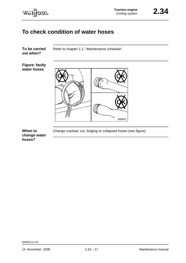
Traction engineCooling system 2.34
To check condition of water hoses
To be carried out when?
Refer to chapter 1.1, “Maintenance schedule”.
Figure: faulty water hoses
When to change water hoses?
Change cracked, cut, bulging or collapsed hoses (see figure).
000006 en-US
14 November 2008 Maintenance manual
.
2.34 – 17
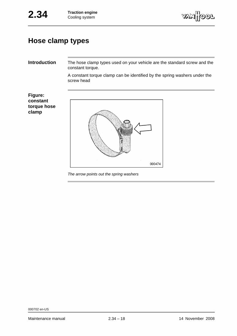
2.34 Traction engineCooling system
Hose clamp types
Introduction The hose clamp types used on your vehicle are the standard screw and the constant torque.
A constant torque clamp can be identified by the spring washers under the screw head
Figure: constant torque hose clamp
The arrow points out the spring washers
000702 en-US
Maintenance manual 14 November 2008
.
2.34 – 18

Traction engineCooling system 2.34
To check hose clamps tightening torque
To be carried out when?
Refer to chapter 1.1, "Maintenance schedule".
Tightening torques
Refer to "Technical data" at the end of this chapter.
Retorque constant torque hose clamps?
Constant torque hose clamps keep their sealing pressure, when the hose swells or shrinks. Therefore they need not be retorqued after installation.
Visual torque check: the screw tip of a properly torqued constant torque clamp extends approximately 0.24 in beyond the housing.
Figure: checking value of constant torque hose clamps
000007 en-US
14 November 2008 Maintenance manual
.
2.34 – 19
2.34 Traction engineCooling system
Fan clutch types
What clutch type on your vehicle?
Your vehicle can be equipped with a 2-speed (one step) or 3-speed (two step) clutch.
Clutch type Identification
2-speed One single connector on the clutch unit.
3-speed Two connectors on the clutch unit (one for each clutch step).
000329 en-US
Maintenance manual 14 November 2008
.
2.34 – 20
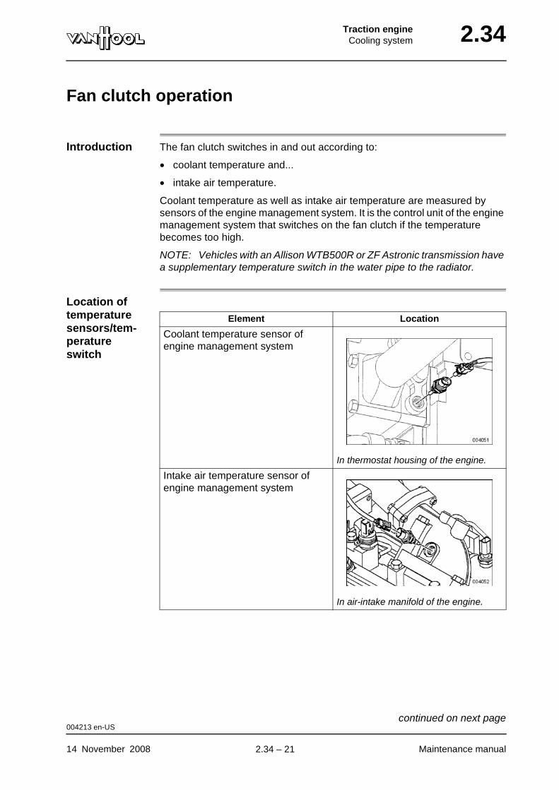
Traction engineCooling system 2.34
Fan clutch operation
Introduction The fan clutch switches in and out according to:
• coolant temperature and...
• intake air temperature.
Coolant temperature as well as intake air temperature are measured by sensors of the engine management system. It is the control unit of the engine management system that switches on the fan clutch if the temperature becomes too high.
NOTE: Vehicles with an Allison WTB500R or ZF Astronic transmission have a supplementary temperature switch in the water pipe to the radiator.
Location of temperature sensors/tem-perature switch
Element Location
Coolant temperature sensor of engine management system
In thermostat housing of the engine.
Intake air temperature sensor of engine management system
In air-intake manifold of the engine.
004213 en-US
14 November 2008 Maintenance manual
continued on next page.
2.34 – 21
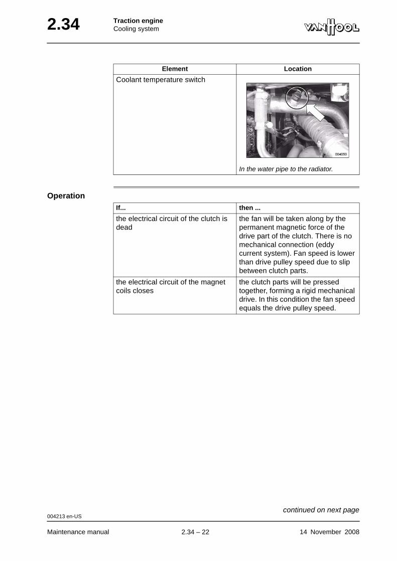
2.34 Traction engineCooling system
Operation
Coolant temperature switch
In the water pipe to the radiator.
Element Location
If... then ...
the electrical circuit of the clutch is dead
the fan will be taken along by the permanent magnetic force of the drive part of the clutch. There is no mechanical connection (eddy current system). Fan speed is lower than drive pulley speed due to slip between clutch parts.
the electrical circuit of the magnet coils closes
the clutch parts will be pressed together, forming a rigid mechanical drive. In this condition the fan speed equals the drive pulley speed.
004213 en-US
Maintenance manual 14 November 2008
continued on next page.
2.34 – 22
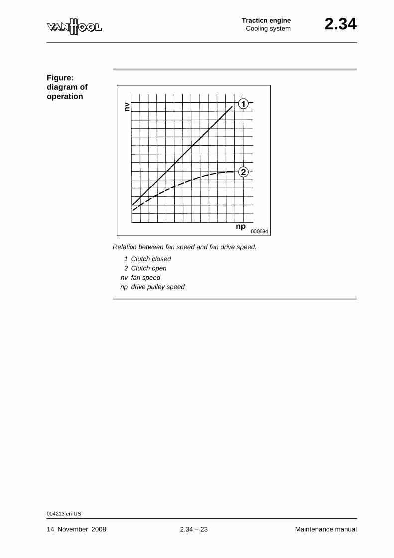
Traction engineCooling system 2.34
Figure: diagram of operation
Relation between fan speed and fan drive speed.
1 Clutch closed2 Clutch open
nv fan speednp drive pulley speed
004213 en-US
14 November 2008 Maintenance manual
.
2.34 – 23
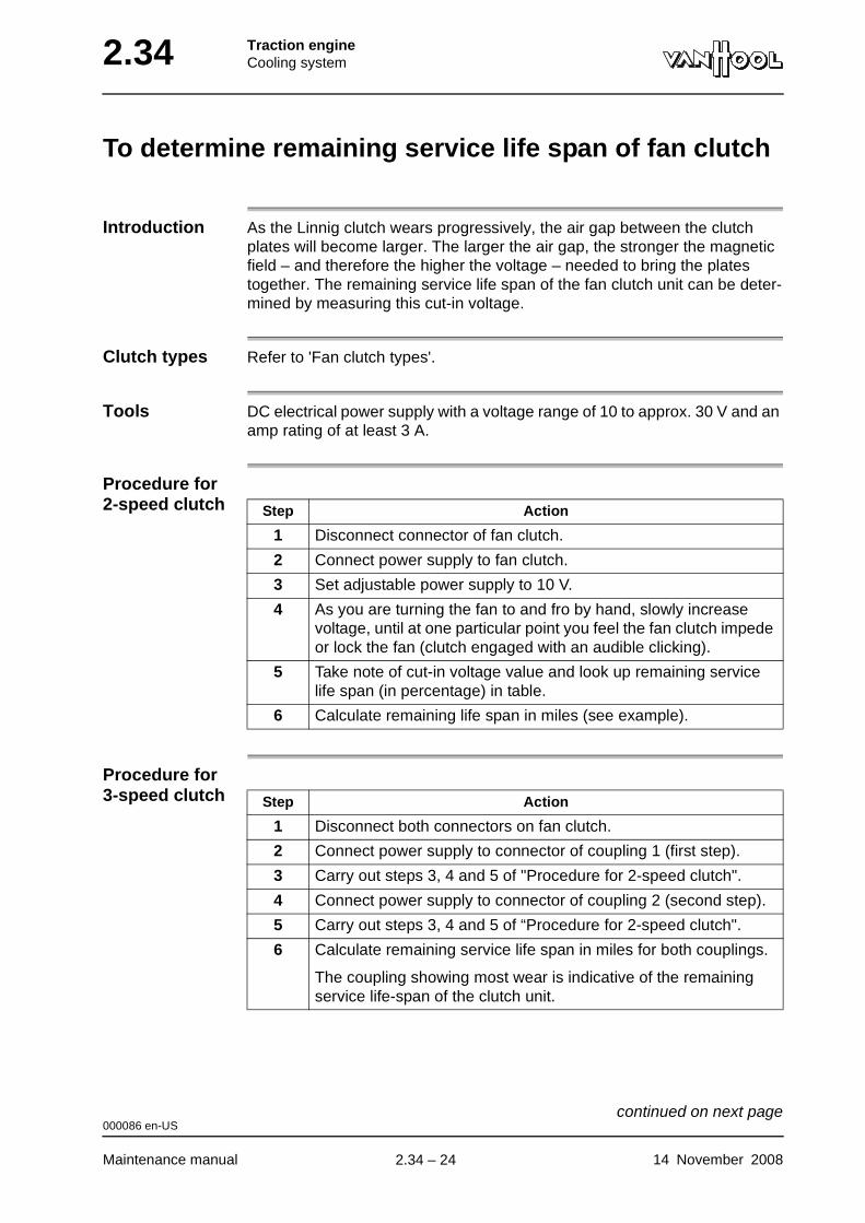
2.34 Traction engineCooling system
To determine remaining service life span of fan clutch
Introduction As the Linnig clutch wears progressively, the air gap between the clutch plates will become larger. The larger the air gap, the stronger the magnetic field – and therefore the higher the voltage – needed to bring the plates together. The remaining service life span of the fan clutch unit can be deter-mined by measuring this cut-in voltage.
Clutch types Refer to 'Fan clutch types'.
Tools DC electrical power supply with a voltage range of 10 to approx. 30 V and an amp rating of at least 3 A.
Procedure for 2-speed clutch
Procedure for 3-speed clutch
Step Action
1 Disconnect connector of fan clutch.
2 Connect power supply to fan clutch.
3 Set adjustable power supply to 10 V.
4 As you are turning the fan to and fro by hand, slowly increase voltage, until at one particular point you feel the fan clutch impede or lock the fan (clutch engaged with an audible clicking).
5 Take note of cut-in voltage value and look up remaining service life span (in percentage) in table.
6 Calculate remaining life span in miles (see example).
Step Action
1 Disconnect both connectors on fan clutch.
2 Connect power supply to connector of coupling 1 (first step).
3 Carry out steps 3, 4 and 5 of "Procedure for 2-speed clutch".
4 Connect power supply to connector of coupling 2 (second step).
5 Carry out steps 3, 4 and 5 of “Procedure for 2-speed clutch".
6 Calculate remaining service life span in miles for both couplings.
The coupling showing most wear is indicative of the remaining service life-span of the clutch unit.
000086 en-US
Maintenance manual 14 November 2008
continued on next page.
2.34 – 24
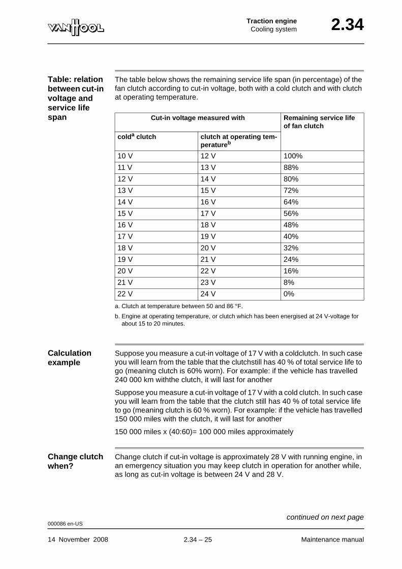
Traction engineCooling system 2.34
Table: relation between cut-in voltage and service life span
The table below shows the remaining service life span (in percentage) of the fan clutch according to cut-in voltage, both with a cold clutch and with clutch at operating temperature.
Calculation example
Suppose you measure a cut-in voltage of 17 V with a coldclutch. In such case you will learn from the table that the clutchstill has 40 % of total service life to go (meaning clutch is 60% worn). For example: if the vehicle has travelled 240 000 km withthe clutch, it will last for another
Suppose you measure a cut-in voltage of 17 V with a cold clutch. In such case you will learn from the table that the clutch still has 40 % of total service life to go (meaning clutch is 60 % worn). For example: if the vehicle has travelled 150 000 miles with the clutch, it will last for another
150 000 miles x (40:60)= 100 000 miles approximately
Change clutch when?
Change clutch if cut-in voltage is approximately 28 V with running engine, in an emergency situation you may keep clutch in operation for another while, as long as cut-in voltage is between 24 V and 28 V.
Cut-in voltage measured with Remaining service life of fan clutch
colda clutch
a. Clutch at temperature between 50 and 86 °F.
clutch at operating tem-peratureb
b. Engine at operating temperature, or clutch which has been energised at 24 V-voltage for about 15 to 20 minutes.
10 V 12 V 100%
11 V 13 V 88%
12 V 14 V 80%
13 V 15 V 72%
14 V 16 V 64%
15 V 17 V 56%
16 V 18 V 48%
17 V 19 V 40%
18 V 20 V 32%
19 V 21 V 24%
20 V 22 V 16%
21 V 23 V 8%
22 V 24 V 0%
000086 en-US
14 November 2008 Maintenance manual
continued on next page.
2.34 – 25
2.34 Traction engineCooling system
No new clutch available immediately?
As on-board voltage is approximately 28 V with running engine, in an emer-gency situation you may keep clutch in operation for another while, as long as cut-in voltage is between 24 V and 28 V.
000086 en-US
Maintenance manual 14 November 2008
.
2.34 – 26
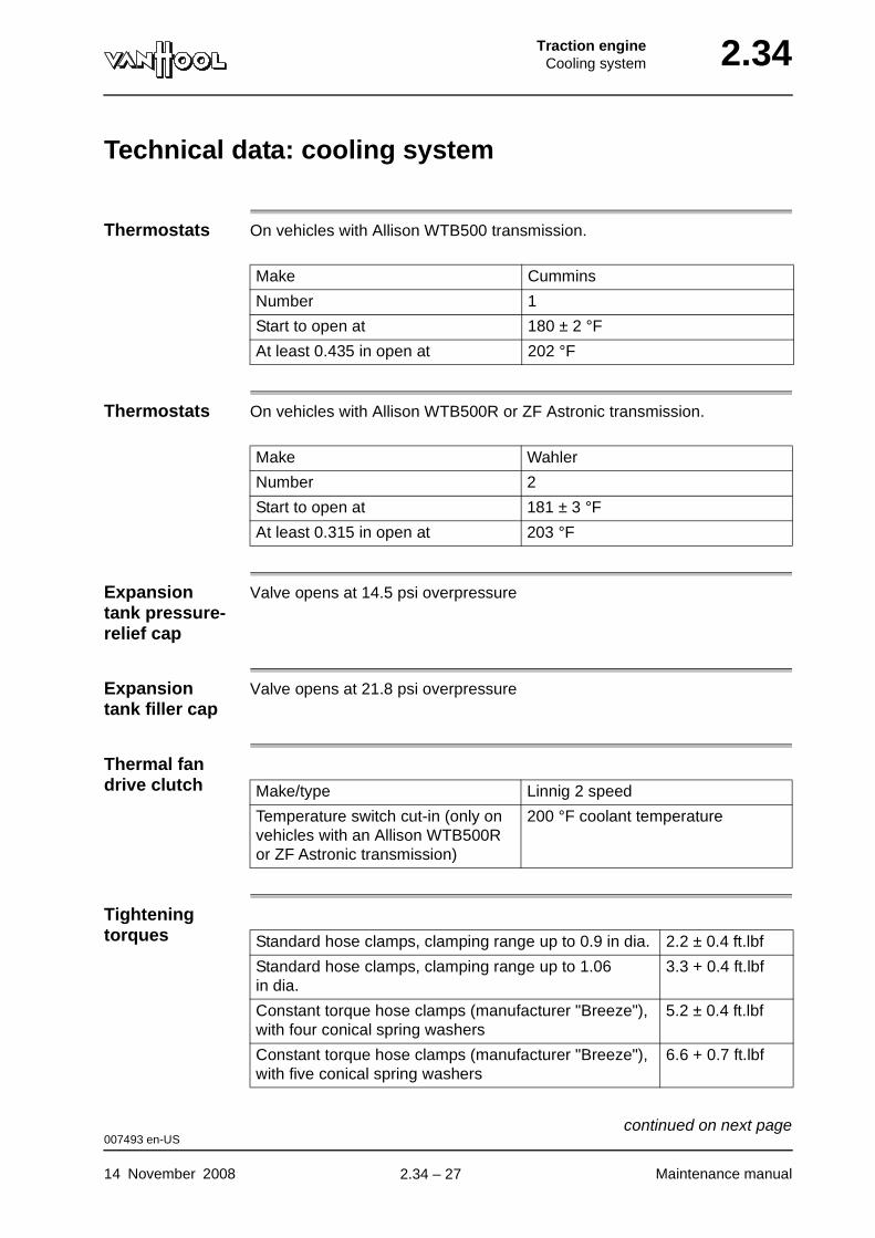
Traction engineCooling system 2.34
Technical data: cooling system
Thermostats On vehicles with Allison WTB500 transmission.
Thermostats On vehicles with Allison WTB500R or ZF Astronic transmission.
Expansion tank pressure-relief cap
Valve opens at 14.5 psi overpressure
Expansion tank filler cap
Valve opens at 21.8 psi overpressure
Thermal fan drive clutch
Tightening torques
Make Cummins
Number 1
Start to open at 180 ± 2 °F
At least 0.435 in open at 202 °F
Make Wahler
Number 2
Start to open at 181 ± 3 °F
At least 0.315 in open at 203 °F
Make/type Linnig 2 speed
Temperature switch cut-in (only on vehicles with an Allison WTB500R or ZF Astronic transmission)
200 °F coolant temperature
Standard hose clamps, clamping range up to 0.9 in dia. 2.2 ± 0.4 ft.lbf
Standard hose clamps, clamping range up to 1.06 in dia.
3.3 + 0.4 ft.lbf
Constant torque hose clamps (manufacturer "Breeze"), with four conical spring washers
5.2 ± 0.4 ft.lbf
Constant torque hose clamps (manufacturer "Breeze"), with five conical spring washers
6.6 + 0.7 ft.lbf
007493 en-US
14 November 2008 Maintenance manual
continued on next page.
2.34 – 27
2.34 Traction engineCooling system
007493 en-US
Maintenance manual 14 November 2008
.
2.34 – 28

Traction engineCooling system 2.34
Special tools: cooling system
Ordering number Description Figure
Fleetguard CC2606 Test kit for measuring the DCA4-concentration
Van Hool 10527208 Cleaning tool for radiator and charge-air cooler
Van Hool 10772040 Coupling for drain nipple on water pipe of engine cooling system
004215 en-US
14 November 2008 Maintenance manual
.
2.34 – 29

2.34 Traction engineCooling system
This page has been intentionally left blank.
004215 en-US
Maintenance manual 14 November 20082.34 – 30
Traction engineLubrication system 2.38
Chapter 38: Lubrication system
Overview
Introduction This chapter deals with the lubrication system.
Number of pages
8
Chapter publi-cation date
2 January 2008
Contents
Topic See page
To check engine oil level 2.38-2
To change oil 2.38-4
To change oil filter 2.38-6
Technical data: lubrication system 2.38-8
2 January 2008 Maintenance manual
.
2.38 – 1
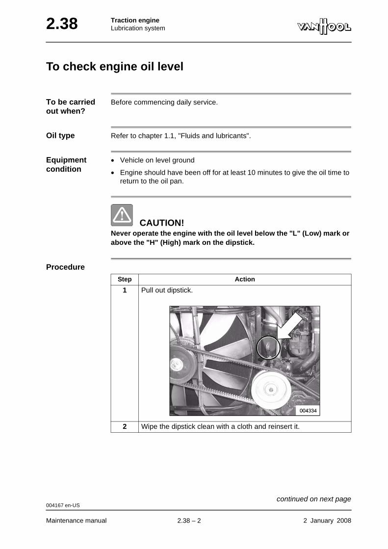
2.38 Traction engineLubrication system
To check engine oil level
To be carried out when?
Before commencing daily service.
Oil type Refer to chapter 1.1, "Fluids and lubricants".
Equipment condition
• Vehicle on level ground
• Engine should have been off for at least 10 minutes to give the oil time to return to the oil pan.
CAUTION!Never operate the engine with the oil level below the "L" (Low) mark or above the "H" (High) mark on the dipstick.
Procedure
Step Action
1 Pull out dipstick.
2 Wipe the dipstick clean with a cloth and reinsert it.
004167 en-US
Maintenance manual 2 January 2008
continued on next page.
2.38 – 2
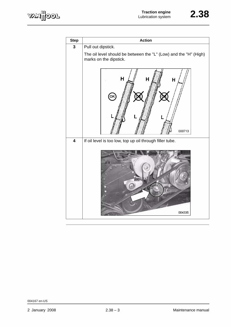
Traction engineLubrication system 2.38
3 Pull out dipstick.
The oil level should be between the "L" (Low) and the "H" (High) marks on the dipstick.
4 If oil level is too low, top up oil through filler tube.
Step Action
004167 en-US
2 January 2008 Maintenance manual
.
2.38 – 3
2.38 Traction engineLubrication system
To change oil
To be carried out when?
Refer to chapter 1.1, "Maintenance schedule".
Oil type Refer to chapter 1.1, "Fluids and lubricants".
Consumables
Tightening torques
Refer to "Technical data" at the end of this chapter.
Equipment condition
Warm engine (coolant temperature 140 °F)
WARNING!Used engine oil is toxic and carcinogenic. Avoid prolonged contact with the skin and inhalation of the fumes.
WARNING!Hot oil flowing out of the oil pan can cause scalds. Avoid contact with the skin.
Procedure
Sealing-ring for engine oil drain plug
Step Action
1
WARNING!Dispose of the used engine oil in accordance with environ-mental regulations.
Remove the drain plug from the oil pan and allow oil to drain.
004169 en-US
Maintenance manual 2 January 2008
continued on next page.
2.38 – 4

Traction engineLubrication system 2.38
2 Clean the drain plug. Screw the drain plug with a new sealing-ring back into the oil pan and tighten to the prescribed torque.
3 Change the oil filter (refer to "To change oil filter").
4 Fill oil pan with clean oil through filler tube, until "H" (High) mark on dipstick is reached.
5 Start the engine.
6 Check the drain plug and oil filter for leaks.
7 Stop the engine. Wait a few minutes and check the oil level with the dipstick. If necessary, add oil, until the level reaches "H" (High) mark on the dipstick.
Step Action
004169 en-US
2 January 2008 Maintenance manual
.
2.38 – 5
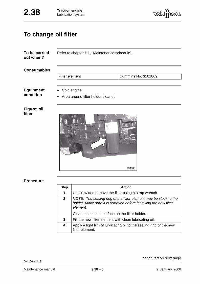
2.38 Traction engineLubrication system
To change oil filter
To be carried out when?
Refer to chapter 1.1, "Maintenance schedule".
Consumables
Equipment condition
• Cold engine
• Area around filter holder cleaned
Figure: oil filter
Procedure
Filter element Cummins No. 3101869
Step Action
1 Unscrew and remove the filter using a strap wrench.
2 NOTE: The sealing ring of the filter element may be stuck to the holder. Make sure it is removed before installing the new filter element.
Clean the contact surface on the filter holder.
3 Fill the new filter element with clean lubricating oil.
4 Apply a light film of lubricating oil to the sealing ring of the new filter element.
004166 en-US
Maintenance manual 2 January 2008
continued on next page.
2.38 – 6

Traction engineLubrication system 2.38
5
CAUTION!Overtightening the filter element can distort the threads or damage the sealing ring.
Install filter element on the holder. Follow the instructions from the filter manufacturer.
Step Action
004166 en-US
2 January 2008 Maintenance manual
.
2.38 – 7
2.38 Traction engineLubrication system
Technical data: lubrication system
Minimum oil pressure
Tightening torques
At 1 200 rpm 30 psi
At idle speed 10 psi
Drain plug in engine oil pan 65 ft.lbf
003355 en-US
Maintenance manual 2 January 2008
.
2.38 – 8
Traction engineAccessory drive systems 2.46
Chapter 46: Accessory drive systems
Overview
Introduction This chapter deals with the accessory drive systems.
Number of pages
24
Chapter publi-cation date
2 January 2008
Contents
Topic See page
Belt types 2.46-2
To check belt tension 2.46-3
To check condition of V-belts 2.46-5
To check condition of V-ribbed belt 2.46-6
Climate-control compressor: operation of tensioning system 2.46-7
Climate-control compressor: to adjust belt 2.46-9
Climate-control compressor: to replace belt 2.46-10
Climate-control compressor: to check/adjust stops of com-pressor seat
2.46-12
Climate-control compressor: to grease compressor seat bearings
2.46-13
Fan: to adjust belts 2.46-14
Fan: to replace belts 2.46-15
Alternator secured to engine block: to adjust tension arm of automatic belt tensioner after installing a new belt
2.46-16
Alternator secured to engine block: to replace belt 2.46-18
Alternator secured to climate-control compressor: to adjust belt
2.46-20
Alternator secured to climate-control compressor: to replace belt
2.46-22
Technical data: accessory drive systems 2.46-23
Special tools: accessory drive systems 2.46-24
2 January 2008 Maintenance manual
.
2.46 – 1

2.46 Traction engineAccessory drive systems
Belt types
Figure: belt types
Most common belt types on Van Hool vehicles
1 Single V-belt2 V-ribbed belt3 Dual V-belt4 Triple V-belt
000038 en-US
Maintenance manual 2 January 2008
.
2.46 – 2

Traction engineAccessory drive systems 2.46
To check belt tension
To be carried out when?
Refer to chapter 1.1, "Maintenance schedule".
Special tools
Checking values
Refer to "Technical data" at the end of this chapter.
Figure: "Krikit I"
1 Indicator arm2 Pressure pad3 Tension scale
Which belts should be checked?
Measure the tension of each belt of each drive.
Tension gauge Gates No. For use on
Krikit I 740100071 Single V-belts
Krikit II 740100072 V-ribbed belts or multi-V-belts
000039 en-US
2 January 2008 Maintenance manual
continued on next page.
2.46 – 3

2.46 Traction engineAccessory drive systems
Procedure
Step Action
1 Adjust the tension gauge to zero by pushing the indicator arm (1) down as far as possible.
2 Place the gauge on the belt, halfway between the pulleys.
3 Now slowly push the pressure pad (2) at a right angle towards the belt surface, until the gauge makes a click sound. Do not keep pushing after hearing this click sound, otherwise the gauge will provide an incorrect reading. Note that the indicator arm (1) must stay in position until step 4 has been completed.
4 Read the tension value at the point where the top part of the indi-cator arm crosses the Newton (or kilogram) Scale. Arrow (3) in the figure indicates the crossing point.
5 Compare this read value to the prescribed tension.
000039 en-US
Maintenance manual 2 January 2008
.
2.46 – 4
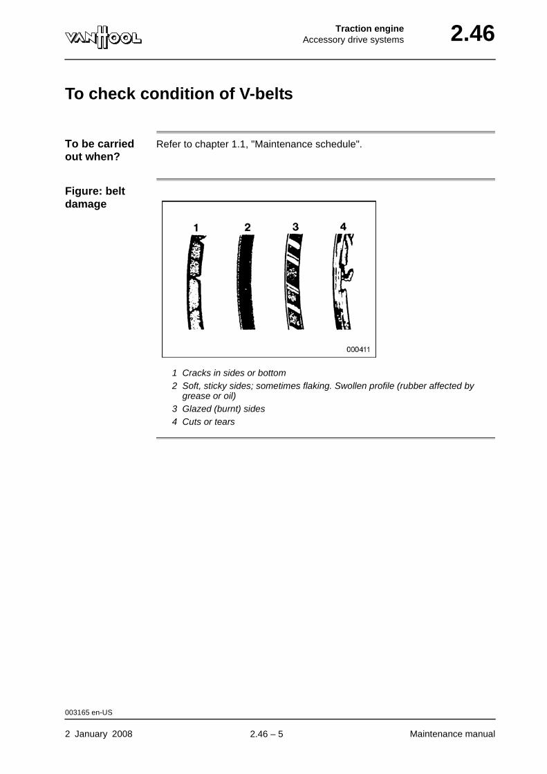
Traction engineAccessory drive systems 2.46
To check condition of V-belts
To be carried out when?
Refer to chapter 1.1, "Maintenance schedule".
Figure: belt damage
1 Cracks in sides or bottom2 Soft, sticky sides; sometimes flaking. Swollen profile (rubber affected by
grease or oil)3 Glazed (burnt) sides4 Cuts or tears
003165 en-US
2 January 2008 Maintenance manual
.
2.46 – 5
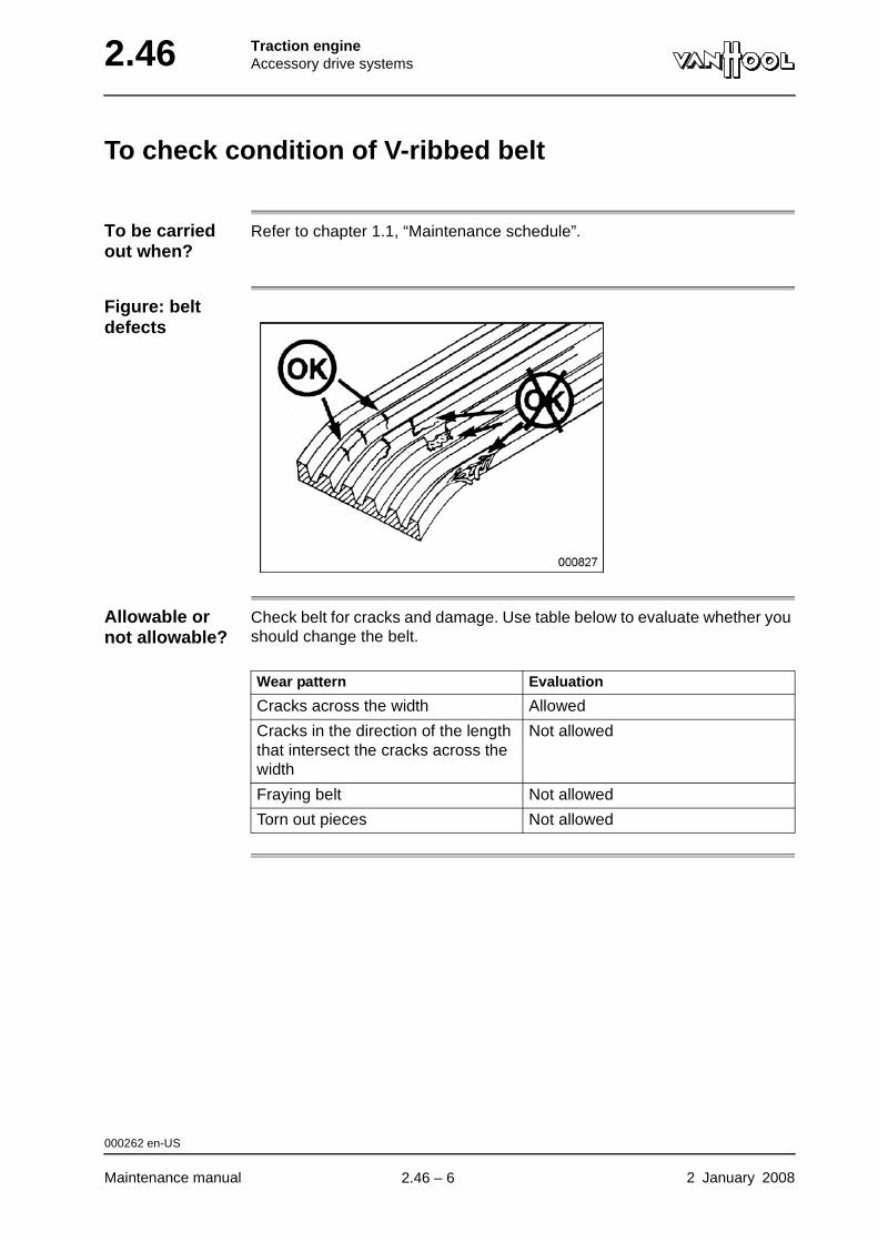
2.46 Traction engineAccessory drive systems
To check condition of V-ribbed belt
To be carried out when?
Refer to chapter 1.1, “Maintenance schedule”.
Figure: belt defects
Allowable or not allowable?
Check belt for cracks and damage. Use table below to evaluate whether you should change the belt.
Wear pattern Evaluation
Cracks across the width Allowed
Cracks in the direction of the length that intersect the cracks across the width
Not allowed
Fraying belt Not allowed
Torn out pieces Not allowed
000262 en-US
Maintenance manual 2 January 2008
.
2.46 – 6
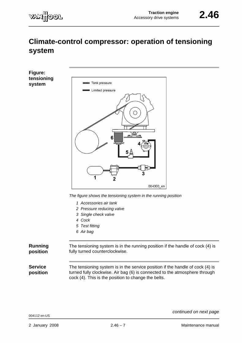
Traction engineAccessory drive systems 2.46
Climate-control compressor: operation of tensioning system
Figure: tensioning system
The figure shows the tensioning system in the running position
1 Accessories air tank2 Pressure reducing valve3 Single check valve4 Cock5 Test fitting6 Air bag
Running position
The tensioning system is in the running position if the handle of cock (4) is fully turned counterclockwise.
Service position
The tensioning system is in the service position if the handle of cock (4) is turned fully clockwise. Air bag (6) is connected to the atmosphere through cock (4). This is the position to change the belts.
004112 en-US
2 January 2008 Maintenance manual
continued on next page.
2.46 – 7
2.46 Traction engineAccessory drive systems
Operation in running position
In the running position the air bag (6) receives compressed air from the accessories air tank, through pressure reducing valve (2), check valve (3), and cock (4). The pressure reducing valve ensures that the pressure in the air bag remains constant. This way the belt tension is kept constant as well.
004112 en-US
Maintenance manual 2 January 2008
.
2.46 – 8

Traction engineAccessory drive systems 2.46
Climate-control compressor: to adjust belt
Setting values Refer to "Technical data" at the end of this chapter.
Equipment condition
• Air system charged to maximum operating pressure
• Handle of cock in compressed-air line of tensioning system turned fully counterclockwise (running position).
Figure: pressure reducing valve
1 Protection cover2 Exhaust valve3 Adjusting screw
Procedure
Step Action
1 Turn protection cover (1) until the attachments inside are free. Remove the cover of the pressure reducing valve.
2 Turn adjusting screw (3), until prescribed belt tension is reached:
• to increase tension: clockwise.
• to diminish tension: counterclockwise.
3 Check if rubber exhaust valve (2) is positioned correctly.
4 Re-install cover (1).
000043 en-US
2 January 2008 Maintenance manual
.
2.46 – 9
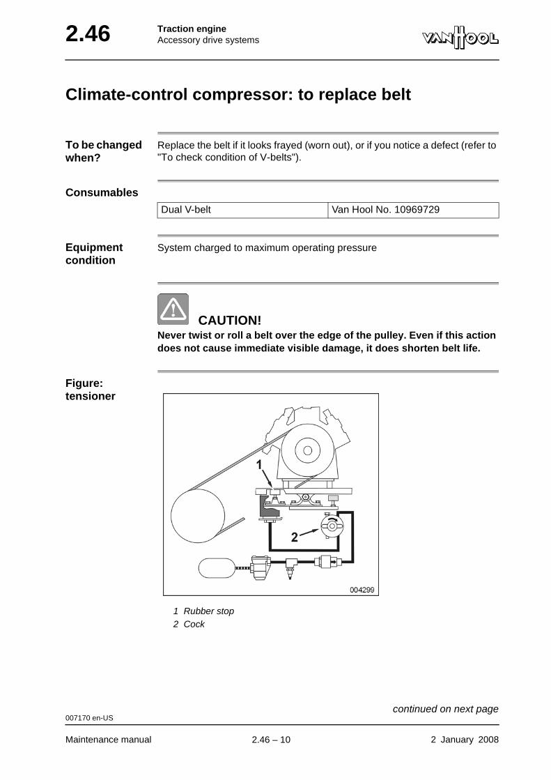
2.46 Traction engineAccessory drive systems
Climate-control compressor: to replace belt
To be changed when?
Replace the belt if it looks frayed (worn out), or if you notice a defect (refer to "To check condition of V-belts").
Consumables
Equipment condition
System charged to maximum operating pressure
CAUTION!Never twist or roll a belt over the edge of the pulley. Even if this action does not cause immediate visible damage, it does shorten belt life.
Figure: tensioner
1 Rubber stop2 Cock
Dual V-belt Van Hool No. 10969729
007170 en-US
Maintenance manual 2 January 2008
continued on next page.
2.46 – 10
Traction engineAccessory drive systems 2.46
Procedure
Step Action
1 Screw rubber stop (1) down as far as it will go.
2 Turn the handle of cock (2) fully clockwise.
The air bag of the tensioning system is now without pressure.
3 Remove belt.
4 Install the new belt.
5 Turn the handle of cock (2) fully counterclockwise (running position).
6 Adjust the height of rubber stop (1), refer to "Climate-control com-pressor: to check/adjust stops of climate-control compressor seat".
007170 en-US
2 January 2008 Maintenance manual
.
2.46 – 11
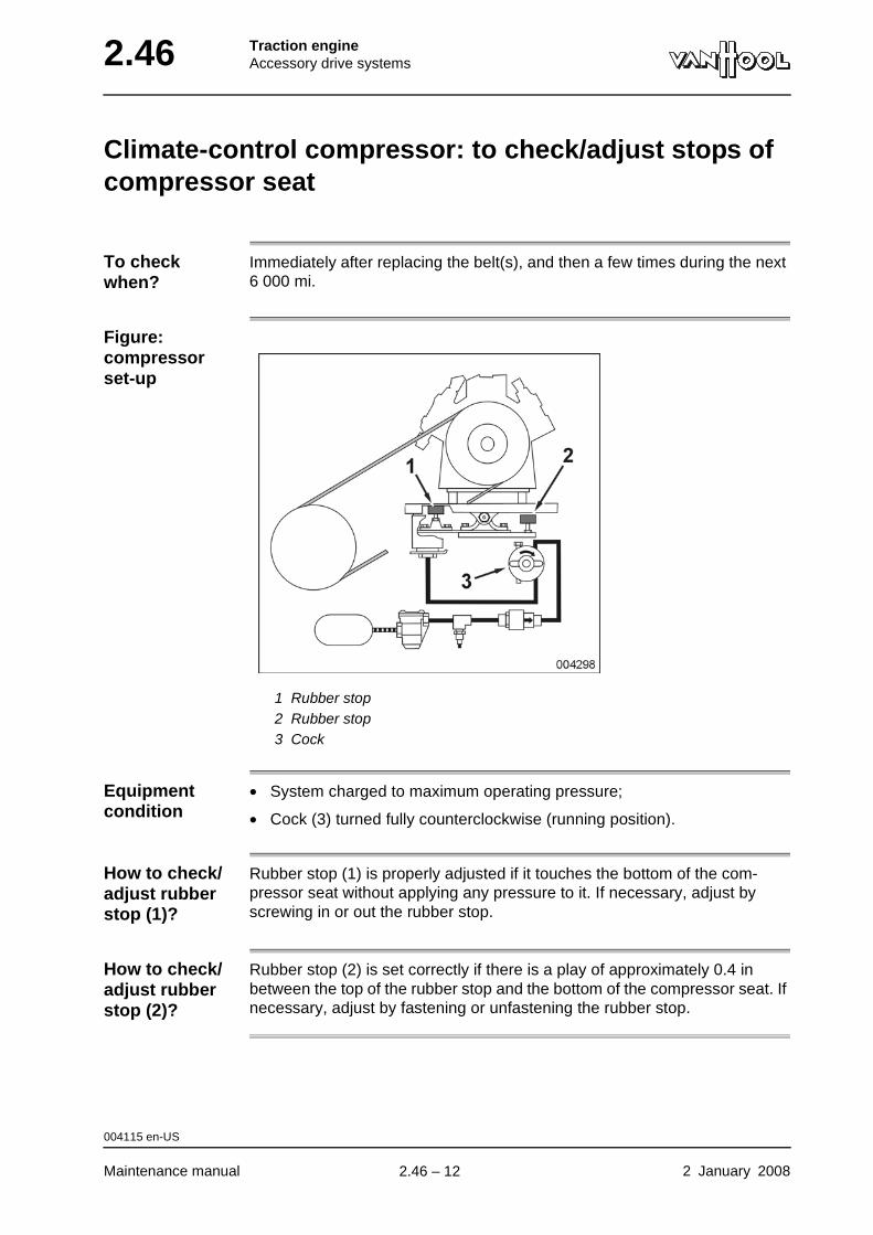
2.46 Traction engineAccessory drive systems
Climate-control compressor: to check/adjust stops of compressor seat
To check when?
Immediately after replacing the belt(s), and then a few times during the next 6 000 mi.
Figure: compressor set-up
1 Rubber stop2 Rubber stop3 Cock
Equipment condition
• System charged to maximum operating pressure;
• Cock (3) turned fully counterclockwise (running position).
How to check/adjust rubber stop (1)?
Rubber stop (1) is properly adjusted if it touches the bottom of the com-pressor seat without applying any pressure to it. If necessary, adjust by screwing in or out the rubber stop.
How to check/adjust rubber stop (2)?
Rubber stop (2) is set correctly if there is a play of approximately 0.4 in between the top of the rubber stop and the bottom of the compressor seat. If necessary, adjust by fastening or unfastening the rubber stop.
004115 en-US
Maintenance manual 2 January 2008
.
2.46 – 12
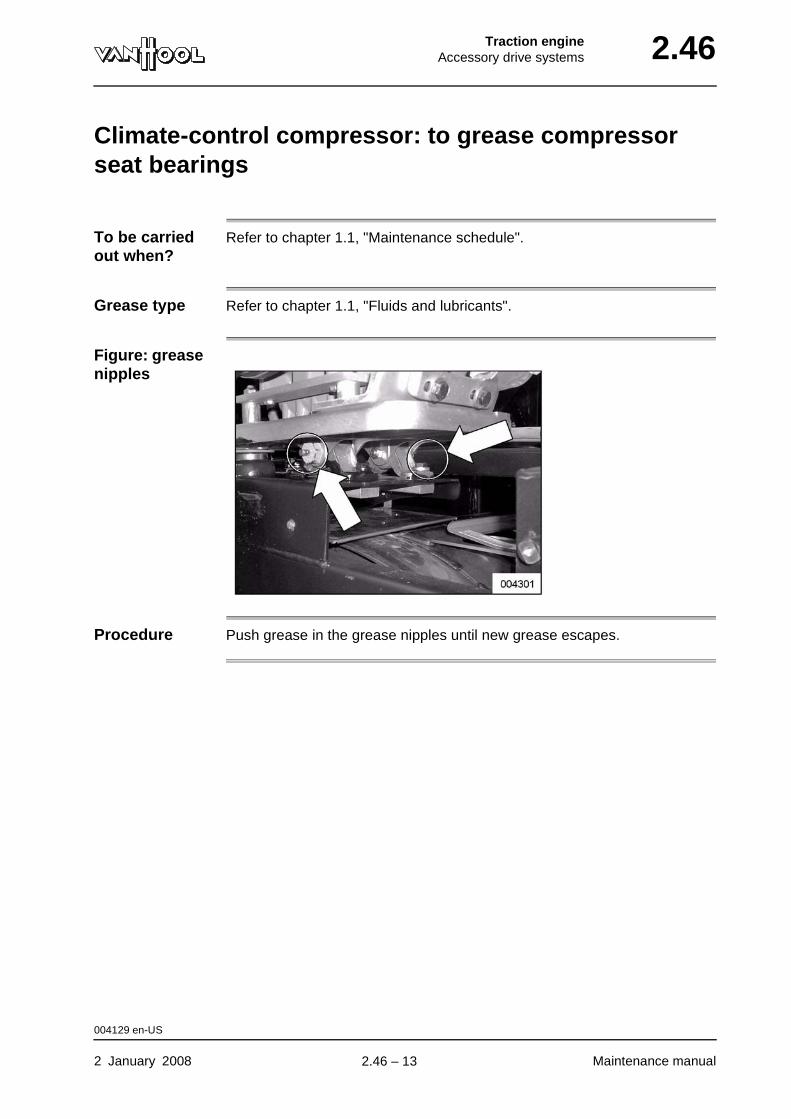
Traction engineAccessory drive systems 2.46
Climate-control compressor: to grease compressor seat bearings
To be carried out when?
Refer to chapter 1.1, "Maintenance schedule".
Grease type Refer to chapter 1.1, "Fluids and lubricants".
Figure: grease nipples
Procedure Push grease in the grease nipples until new grease escapes.
004129 en-US
2 January 2008 Maintenance manual
.
2.46 – 13
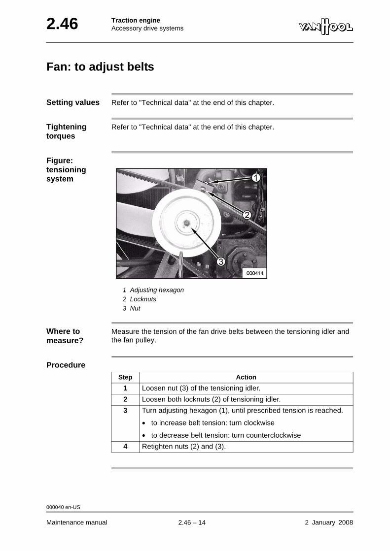
2.46 Traction engineAccessory drive systems
Fan: to adjust belts
Setting values Refer to "Technical data" at the end of this chapter.
Tightening torques
Refer to "Technical data" at the end of this chapter.
Figure: tensioning system
1 Adjusting hexagon2 Locknuts3 Nut
Where to measure?
Measure the tension of the fan drive belts between the tensioning idler and the fan pulley.
Procedure
Step Action
1 Loosen nut (3) of the tensioning idler.
2 Loosen both locknuts (2) of tensioning idler.
3 Turn adjusting hexagon (1), until prescribed tension is reached.
• to increase belt tension: turn clockwise
• to decrease belt tension: turn counterclockwise
4 Retighten nuts (2) and (3).
000040 en-US
Maintenance manual 2 January 2008
.
2.46 – 14
Traction engineAccessory drive systems 2.46
Fan: to replace belts
Consumables
To be changed when?
Replace the belts if they look frayed (worn out), or if you notice a defect (refer to "To check condition of V-belts").
CAUTION!Never twist or roll the belt over the edge of the pulley. Even if this action does not cause immediate visible damage, it does shorten belt life.
Procedure Belts of the same drive must always be changed as a pair.
Retensioning During run-in, a part of the tension will be lost because the new belts will stretch and fall deeper in the grooves of the pulleys. Therefore, re-adjust belt tension to its initial value after the first 20 minutes of operation.
Set of two single V-belts between the engine crankshaft pulley and tensioning idler
Van Hool No. 639602001
Set of two single V-belts between tensioning idler and fan pulley
Van Hool No. 639602001
Step Action
1 Slacken the tensioning system as far as possible; refer to "Fan: to adjust belts".
2 Remove the belts.
3 Install the new belts.
4 Set the belt tension, refer to "Fan: to adjust belts".
007171 en-US
2 January 2008 Maintenance manual
.
2.46 – 15
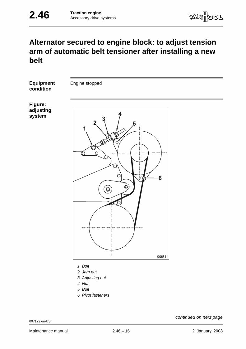
2.46 Traction engineAccessory drive systems
Alternator secured to engine block: to adjust tension arm of automatic belt tensioner after installing a new belt
Equipment condition
Engine stopped
Figure: adjusting system
1 Bolt2 Jam nut3 Adjusting nut4 Nut5 Bolt6 Pivot fasteners
007172 en-US
Maintenance manual 2 January 2008
continued on next page.
2.46 – 16
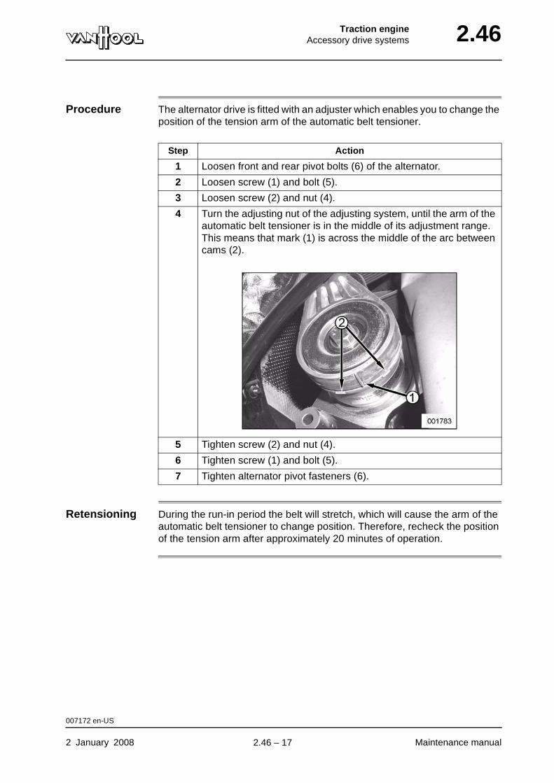
Traction engineAccessory drive systems 2.46
Procedure The alternator drive is fitted with an adjuster which enables you to change the position of the tension arm of the automatic belt tensioner.
Retensioning During the run-in period the belt will stretch, which will cause the arm of the automatic belt tensioner to change position. Therefore, recheck the position of the tension arm after approximately 20 minutes of operation.
Step Action
1 Loosen front and rear pivot bolts (6) of the alternator.
2 Loosen screw (1) and bolt (5).
3 Loosen screw (2) and nut (4).
4 Turn the adjusting nut of the adjusting system, until the arm of the automatic belt tensioner is in the middle of its adjustment range. This means that mark (1) is across the middle of the arc between cams (2).
5 Tighten screw (2) and nut (4).
6 Tighten screw (1) and bolt (5).
7 Tighten alternator pivot fasteners (6).
007172 en-US
2 January 2008 Maintenance manual
.
2.46 – 17
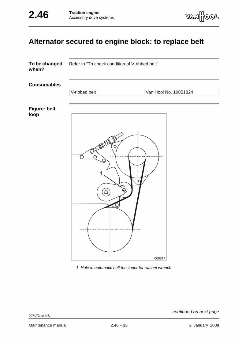
2.46 Traction engineAccessory drive systems
Alternator secured to engine block: to replace belt
To be changed when?
Refer to "To check condition of V-ribbed belt".
Consumables
Figure: belt loop
1 Hole in automatic belt tensioner for ratchet wrench
V-ribbed belt Van Hool No. 10851824
007173 en-US
Maintenance manual 2 January 2008
continued on next page.
2.46 – 18
Traction engineAccessory drive systems 2.46
CAUTION!Never twist or roll the belt over the edge of a pulley. Even if this action does not cause immediate visible damage, it does shorten belt life.
Procedure
Step Action
1 Insert a ratchet wrench with 1/2 inch square drive into hole (1) of the automatic belt tensioner.
2 Relieve the belt tension by turning the ratchet wrench in the opposite direction to the spring tension of the automatic belt ten-sioner.
3 Remove the belt. Carefully let the automatic belt tensioner spring back to the stop.
4 Check all pulleys for damage.
5 Loop the new belt over the alternator pulley.
6 Tighten the automatic belt tensioner. Loop the belt over the drive pulley. Carefully release the automatic belt tensioner against the new belt.
7 Check that the belt rides in the grooves of all the pulleys.
8 Adjust the position of the automatic belt tensioner (refer to "Alter-nator secured to engine block: to adjust tension arm of automatic belt tensioner after installing a new belt").
007173 en-US
2 January 2008 Maintenance manual
.
2.46 – 19
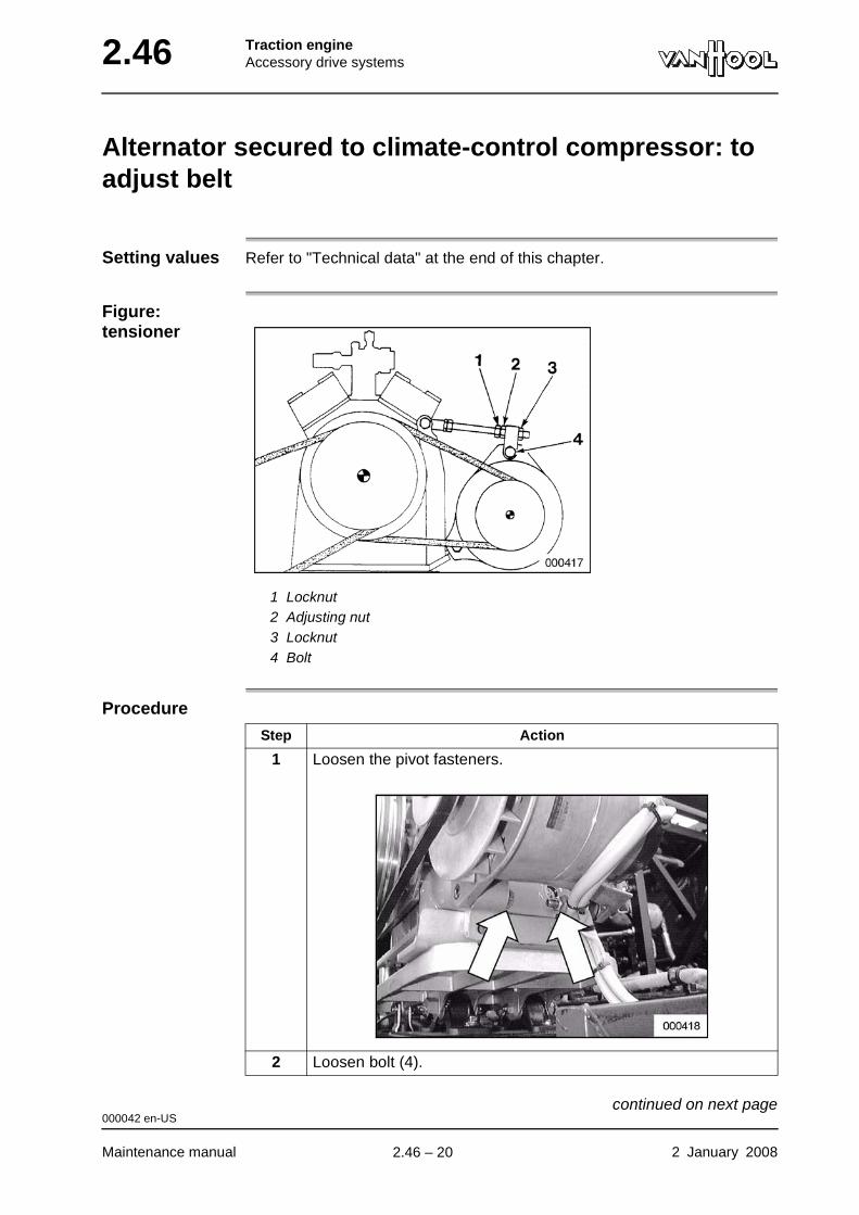
2.46 Traction engineAccessory drive systems
Alternator secured to climate-control compressor: to adjust belt
Setting values Refer to "Technical data" at the end of this chapter.
Figure: tensioner
1 Locknut2 Adjusting nut3 Locknut4 Bolt
Procedure
Step Action
1 Loosen the pivot fasteners.
2 Loosen bolt (4).
000042 en-US
Maintenance manual 2 January 2008
continued on next page.
2.46 – 20
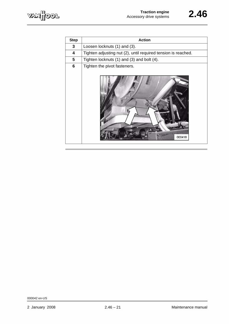
Traction engineAccessory drive systems 2.46
3 Loosen locknuts (1) and (3).
4 Tighten adjusting nut (2), until required tension is reached.
5 Tighten locknuts (1) and (3) and bolt (4).
6 Tighten the pivot fasteners.
Step Action
000042 en-US
2 January 2008 Maintenance manual
.
2.46 – 21
2.46 Traction engineAccessory drive systems
Alternator secured to climate-control compressor: to replace belt
To be changed when?
Replace the belt if it looks frayed (worn out), or if you notice a defect (see under "To check condition of V-belts").
Consumables
CAUTION!Never twist or roll the belt over the edge of the pulley. Even if this action does not cause immediate visible damage, it does shorten belt life.
Procedure
Retensioning During the run-in period the belt will stretch, which will cause the arm of the automatic belt tensioner to change position. Therefore, recheck the position of the tension arm after approximately 20 minutes of operation.
Single V-belt Van Hool No. 639601600
Step Action
1 Slacken the tensioning system as far as possible; refer to "Alter-nator secured to climate-control compressor: to adjust belt".
2 Remove the belt.
3 Install the new belt.
4 Set the belt tension; refer to "Alternator secured to climate-control compressor: to adjust belt".
004118 en-US
Maintenance manual 2 January 2008
.
2.46 – 22
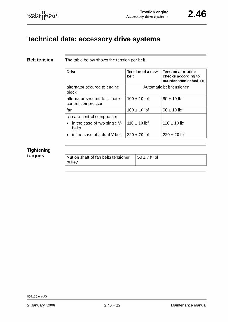
Traction engineAccessory drive systems 2.46
Technical data: accessory drive systems
Belt tension The table below shows the tension per belt.
Tightening torques
Drive Tension of a new belt
Tension at routine checks according to maintenance schedule
alternator secured to engine block
Automatic belt tensioner
alternator secured to climate-control compressor
100 ± 10 lbf 90 ± 10 lbf
fan 100 ± 10 lbf 90 ± 10 lbf
climate-control compressor
• in the case of two single V-belts
110 ± 10 lbf 110 ± 10 lbf
• in the case of a dual V-belt 220 ± 20 lbf 220 ± 20 lbf
Nut on shaft of fan belts tensioner pulley
50 ± 7 ft.lbf
004128 en-US
2 January 2008 Maintenance manual
.
2.46 – 23
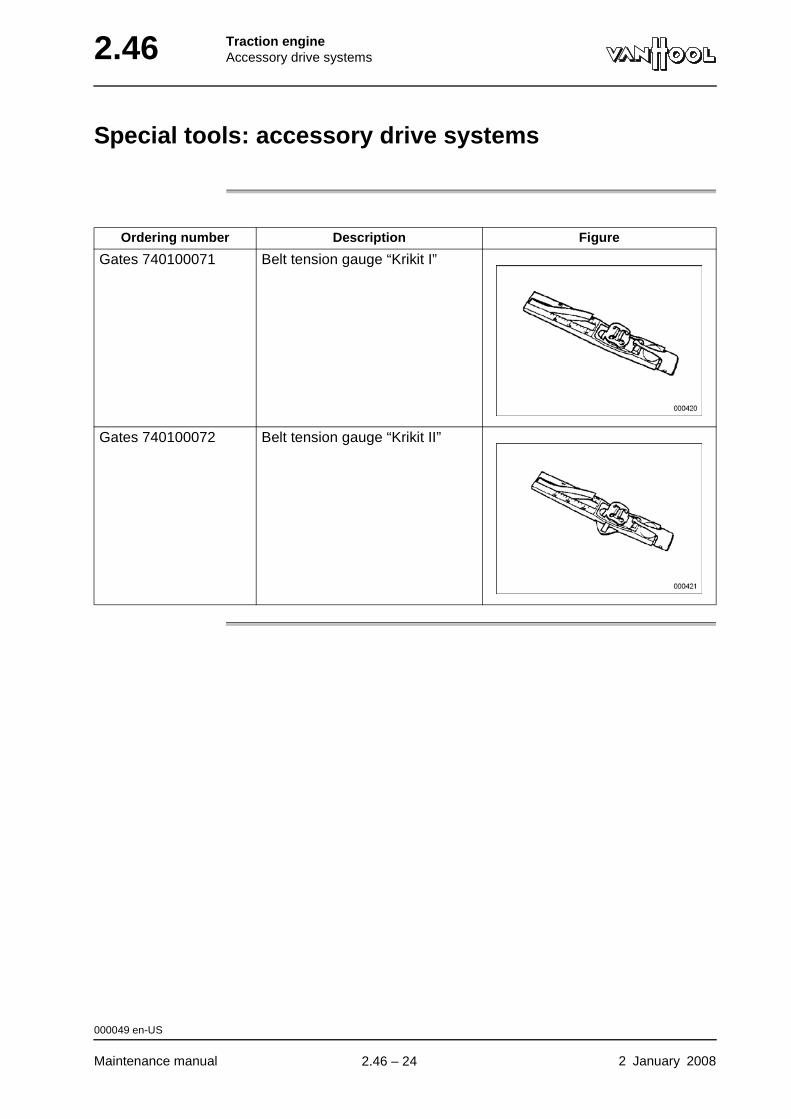
2.46 Traction engineAccessory drive systems
Special tools: accessory drive systems
Ordering number Description Figure
Gates 740100071 Belt tension gauge “Krikit I”
Gates 740100072 Belt tension gauge “Krikit II”
000049 en-US
Maintenance manual 2 January 2008
.
2.46 – 24
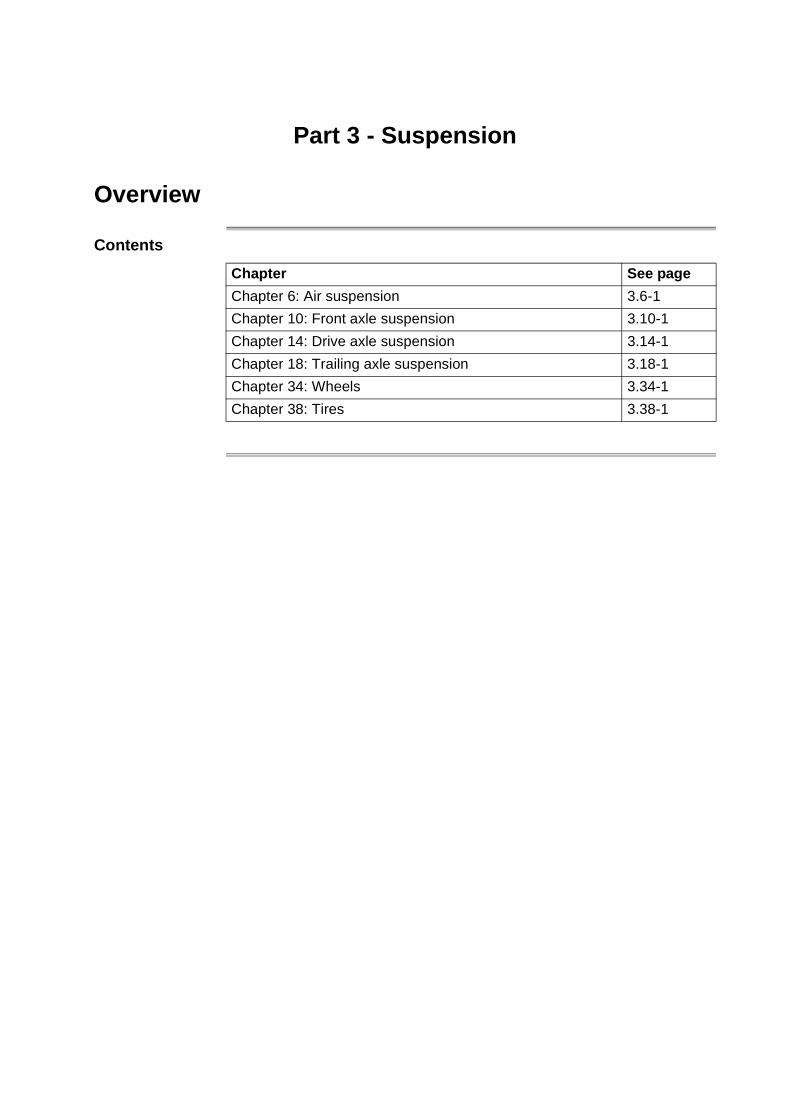
Part 3 - Suspension
Overview
Contents
Chapter See page
Chapter 6: Air suspension 3.6-1
Chapter 10: Front axle suspension 3.10-1
Chapter 14: Drive axle suspension 3.14-1
Chapter 18: Trailing axle suspension 3.18-1
Chapter 34: Wheels 3.34-1
Chapter 38: Tires 3.38-1

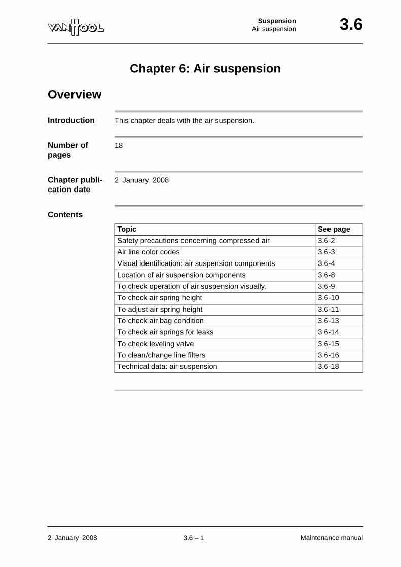
SuspensionAir suspension 3.6
Chapter 6: Air suspension
Overview
Introduction This chapter deals with the air suspension.
Number of pages
18
Chapter publi-cation date
2 January 2008
Contents
Topic See page
Safety precautions concerning compressed air 3.6-2
Air line color codes 3.6-3
Visual identification: air suspension components 3.6-4
Location of air suspension components 3.6-8
To check operation of air suspension visually. 3.6-9
To check air spring height 3.6-10
To adjust air spring height 3.6-11
To check air bag condition 3.6-13
To check air springs for leaks 3.6-14
To check leveling valve 3.6-15
To clean/change line filters 3.6-16
Technical data: air suspension 3.6-18
2 January 2008 Maintenance manual
.
3.6 – 1
3.6 SuspensionAir suspension
Safety precautions concerning compressed air
Cross-reference
Refer to chapter 13.1, "Complete compressed-air system".
000564 en-US
Maintenance manual 2 January 2008
.
3.6 – 2
SuspensionAir suspension 3.6
Air line color codes
Cross-reference
Refer to chapter 13.25, “Air lines”.
000565 en-US
2 January 2008 Maintenance manual
.
3.6 – 3
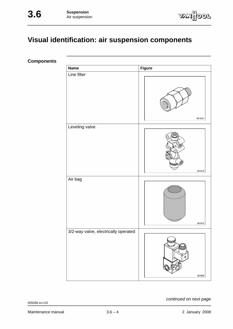
3.6 SuspensionAir suspension
Visual identification: air suspension components
ComponentsName Figure
Line filter
Leveling valve
Air bag
3/2-way valve, electrically operated
005066 en-US
Maintenance manual 2 January 2008
continued on next page.
3.6 – 4
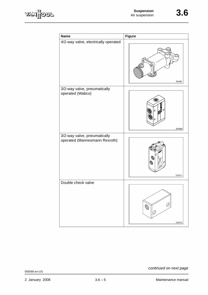
SuspensionAir suspension 3.6
4/2-way valve, electrically operated
3/2-way valve, pneumatically operated (Wabco)
3/2-way valve, pneumatically operated (Mannesmann Rexroth)
Double check valve
Name Figure
005066 en-US
2 January 2008 Maintenance manual
continued on next page.
3.6 – 5
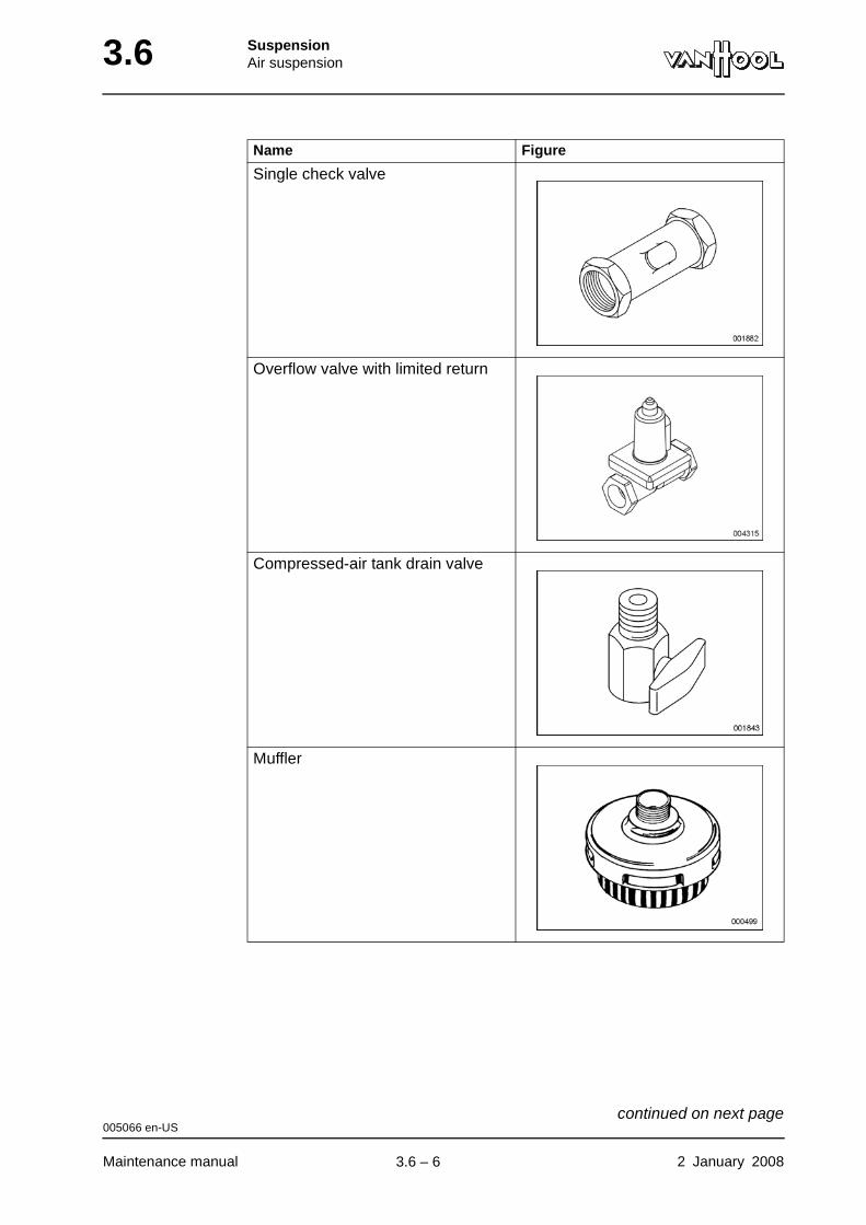
3.6 SuspensionAir suspension
Single check valve
Overflow valve with limited return
Compressed-air tank drain valve
Muffler
Name Figure
005066 en-US
Maintenance manual 2 January 2008
continued on next page.
3.6 – 6
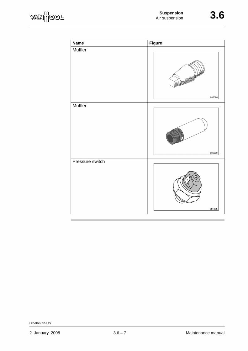
SuspensionAir suspension 3.6
Muffler
Muffler
Pressure switch
Name Figure
005066 en-US
2 January 2008 Maintenance manual
.
3.6 – 7
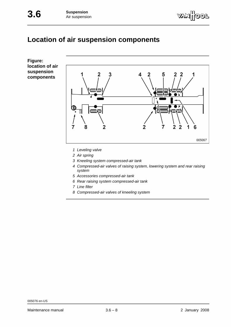
3.6 SuspensionAir suspension
Location of air suspension components
Figure: location of air suspension components
1 Leveling valve2 Air spring3 Kneeling system compressed-air tank4 Compressed-air valves of raising system, lowering system and rear raising
system5 Accessories compressed-air tank6 Rear raising system compressed-air tank7 Line filter8 Compressed-air valves of kneeling system
005076 en-US
Maintenance manual 2 January 2008
.
3.6 – 8
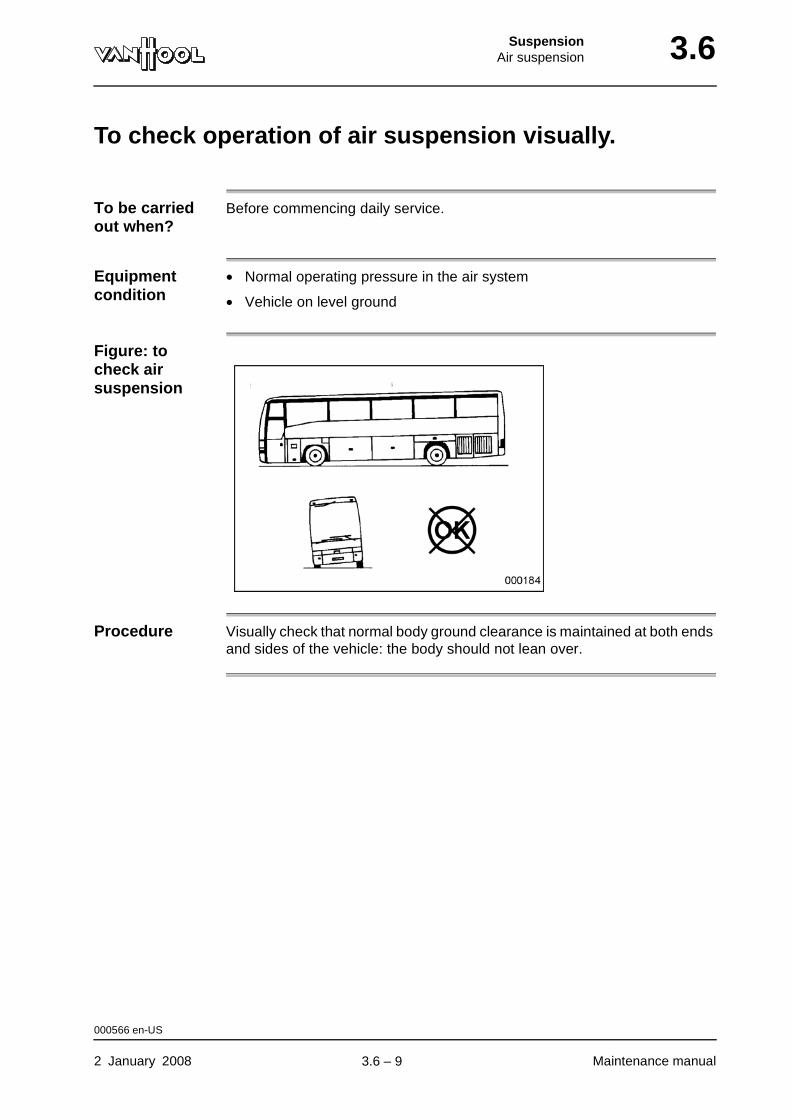
SuspensionAir suspension 3.6
To check operation of air suspension visually.
To be carried out when?
Before commencing daily service.
Equipment condition
• Normal operating pressure in the air system
• Vehicle on level ground
Figure: to check air suspension
Procedure Visually check that normal body ground clearance is maintained at both ends and sides of the vehicle: the body should not lean over.
000566 en-US
2 January 2008 Maintenance manual
.
3.6 – 9
3.6 SuspensionAir suspension
To check air spring height
To be carried out when?
Refer to chapter 1.1, "Maintenance schedule".
Checking values
Refer to "Technical data" at the end of this chapter.
Equipment condition
• Empty vehicle on a flat level surface, over an inspection pit
• Tires equally worn and at the correct inflation pressure
• Air system charged to maximum operating pressure (let the engine idle)
• Vehicles equipped with a kneeling, raising or lowering system: air sus-pension in normal "ride" position
Which air springs should be checked?
Check:
• height of left air spring front suspension, and...
• height of left and right rear air springs of drive axle suspension.
Procedure It is essential to hold the gauge parallel to the spring axis (refer to the figures in "Technical data" at the end of this chapter).
004141 en-US
Maintenance manual 2 January 2008
.
3.6 – 10
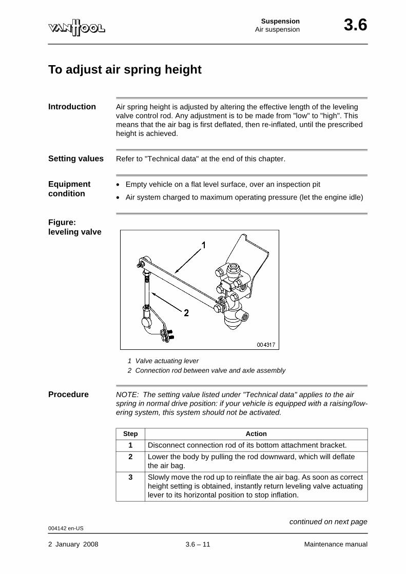
SuspensionAir suspension 3.6
To adjust air spring height
Introduction Air spring height is adjusted by altering the effective length of the leveling valve control rod. Any adjustment is to be made from "low" to "high". This means that the air bag is first deflated, then re-inflated, until the prescribed height is achieved.
Setting values Refer to "Technical data" at the end of this chapter.
Equipment condition
• Empty vehicle on a flat level surface, over an inspection pit
• Air system charged to maximum operating pressure (let the engine idle)
Figure: leveling valve
1 Valve actuating lever2 Connection rod between valve and axle assembly
Procedure NOTE: The setting value listed under "Technical data" applies to the air spring in normal drive position: if your vehicle is equipped with a raising/low-ering system, this system should not be activated.
Step Action
1 Disconnect connection rod of its bottom attachment bracket.
2 Lower the body by pulling the rod downward, which will deflate the air bag.
3 Slowly move the rod up to reinflate the air bag. As soon as correct height setting is obtained, instantly return leveling valve actuating lever to its horizontal position to stop inflation.
004142 en-US
2 January 2008 Maintenance manual
continued on next page.
3.6 – 11
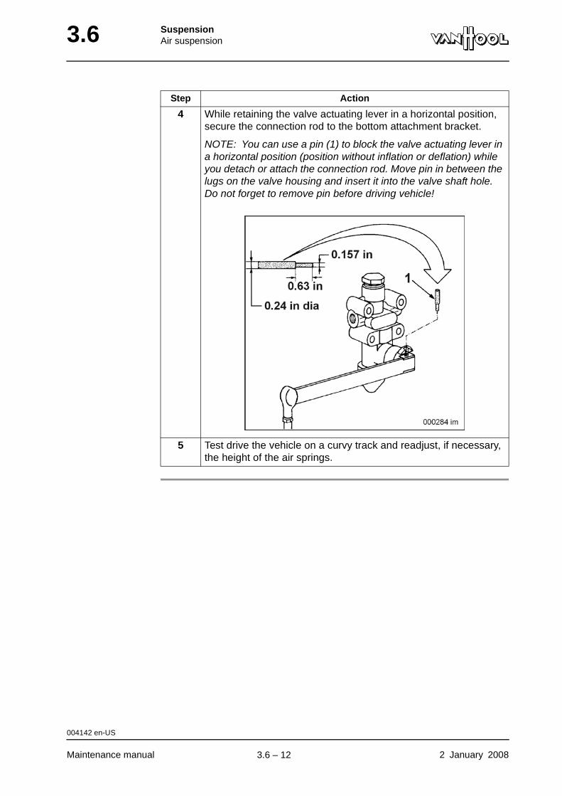
3.6 SuspensionAir suspension
4 While retaining the valve actuating lever in a horizontal position, secure the connection rod to the bottom attachment bracket.
NOTE: You can use a pin (1) to block the valve actuating lever in a horizontal position (position without inflation or deflation) while you detach or attach the connection rod. Move pin in between the lugs on the valve housing and insert it into the valve shaft hole. Do not forget to remove pin before driving vehicle!
5 Test drive the vehicle on a curvy track and readjust, if necessary, the height of the air springs.
Step Action
004142 en-US
Maintenance manual 2 January 2008
.
3.6 – 12
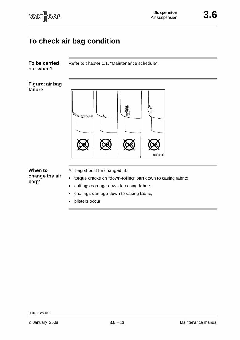
SuspensionAir suspension 3.6
To check air bag condition
To be carried out when?
Refer to chapter 1.1, “Maintenance schedule”.
Figure: air bag failure
When to change the air bag?
Air bag should be changed, if:
• torque cracks on “down-rolling” part down to casing fabric;
• cuttings damage down to casing fabric;
• chafings damage down to casing fabric;
• blisters occur.
000685 en-US
2 January 2008 Maintenance manual
.
3.6 – 13
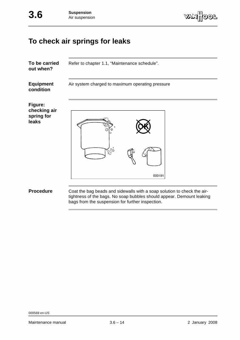
3.6 SuspensionAir suspension
To check air springs for leaks
To be carried out when?
Refer to chapter 1.1, “Maintenance schedule”.
Equipment condition
Air system charged to maximum operating pressure
Figure: checking air spring for leaks
Procedure Coat the bag beads and sidewalls with a soap solution to check the air-tightness of the bags. No soap bubbles should appear. Demount leaking bags from the suspension for further inspection.
000569 en-US
Maintenance manual 2 January 2008
.
3.6 – 14

SuspensionAir suspension 3.6
To check leveling valve
To be carried out when?
Refer to chapter 1.1, "Maintenance schedule".
Equipment condition
A pressure of 115 to 130 psi in the air tanks
Procedure
Step Action
1 Clean the rubber protection cover (1) on the exhaust of the valve, and brush soapy water on it. Look for soap bubbles.
2 If the valve leaks, remove it for repair.
000573 en-US
2 January 2008 Maintenance manual
.
3.6 – 15
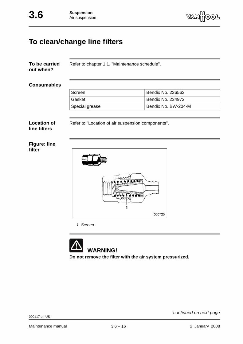
3.6 SuspensionAir suspension
To clean/change line filters
To be carried out when?
Refer to chapter 1.1, "Maintenance schedule".
Consumables
Location of line filters
Refer to "Location of air suspension components".
Figure: line filter
1 Screen
WARNING!Do not remove the filter with the air system pressurized.
Screen Bendix No. 236562
Gasket Bendix No. 234972
Special grease Bendix No. BW-204-M
000117 en-US
Maintenance manual 2 January 2008
continued on next page.
3.6 – 16

SuspensionAir suspension 3.6
Procedure
Step Action
1 Release pressure from air system by actuating drain valve on accessories air tank.
For the location of the air tanks refer to "Location of air tanks" in chapter 13.17.
2 Disconnect air lines from filter body and remove filter.
3 Disassemble filter body in vise.
4 Clean or change filter screen.
5 Reassemble new or cleaned filter screen into filter body. Apply thin film of special grease to new gasket.
6 Re-install filter in air lines.
000117 en-US
2 January 2008 Maintenance manual
.
3.6 – 17
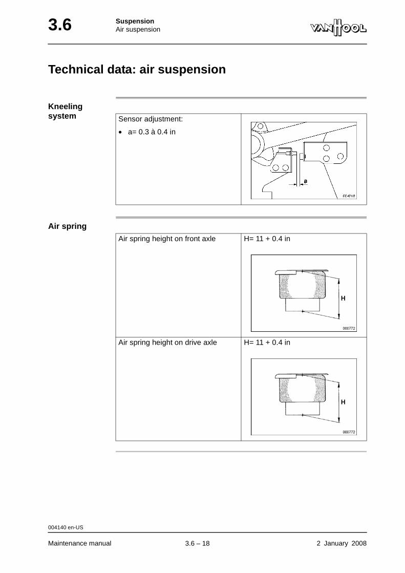
3.6 SuspensionAir suspension
Technical data: air suspension
Kneeling system
Air spring
Sensor adjustment:
• a= 0.3 à 0.4 in
Air spring height on front axle H= 11 + 0.4 in
Air spring height on drive axle H= 11 + 0.4 in
004140 en-US
Maintenance manual 2 January 2008
.
3.6 – 18

SuspensionFront axle suspension 3.10
Chapter 10: Front axle suspension
Overview
Introduction This chapter deals with the front axle suspension.
Number of pages
4
Chapter publi-cation date
2 January 2008
Contents
Topic See page
To check security of suspension components 3.10-2
To check shock absorbers for damage and leakage 3.10-3
Technical data: front axle suspension 3.10-4
2 January 2008 Maintenance manual
.
3.10 – 1

3.10 SuspensionFront axle suspension
To check security of suspension components
Tightening torques
Refer to “Technical data” at the end of this chapter.
Procedure Visually check those bolts, screws and nuts that are locked by means of a cotter pin, a locking plate or locking adhesive (Loctite). The security of all others must be checked mechanically. Retighten, if necessary.
WARNING!Never retighten bolts, screws or nuts that are fitted with locking adhesive, as this would destroy locking properties.
000794 en-US
Maintenance manual 2 January 2008
.
3.10 – 2

SuspensionFront axle suspension 3.10
To check shock absorbers for damage and leakage
To be carried out when?
Refer to chapter 1.1, “Maintenance schedule”.
Figure: shock absorber failure
What to check?
Check the shock absorber for:
• fatigue cracks on rubbers;
• damage at housing;
• oil leaks.
000017 en-US
2 January 2008 Maintenance manual
.
3.10 – 3
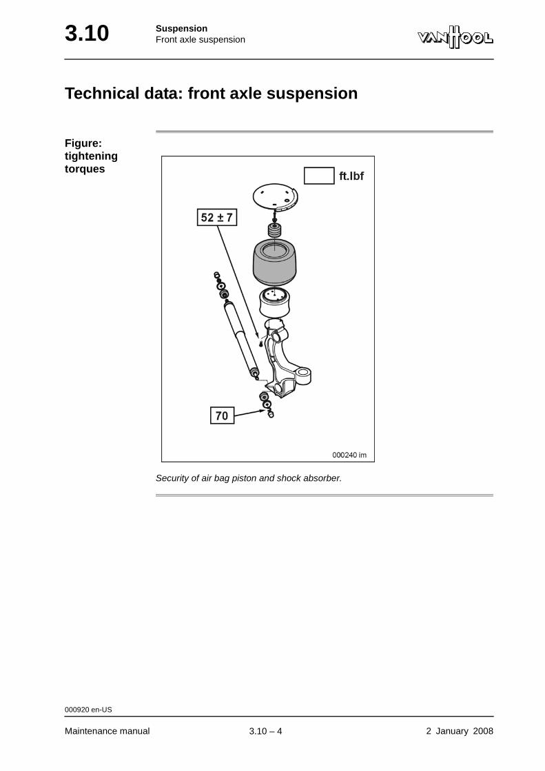
3.10 SuspensionFront axle suspension
Technical data: front axle suspension
Figure: tightening torques
Security of air bag piston and shock absorber.
000920 en-US
Maintenance manual 2 January 2008
.
3.10 – 4
SuspensionDrive axle suspension 3.14
Chapter 14: Drive axle suspension
Overview
Introduction This chapter deals with the drive axle suspension.
Number of pages
8
Chapter publi-cation date
2 January 2008
Contents
Topic See page
To check security of suspension components 3.14-2
To work on or nearby the leaf spring 3.14-3
To check shock absorbers for damage and leakage 3.14-4
Technical data: drive axle suspension 3.14-5
2 January 2008 Maintenance manual
.
3.14 – 1

3.14 SuspensionDrive axle suspension
To check security of suspension components
Tightening torques
Refer to "Technical data" at the end of this chapter.
Procedure Visually check those bolts, screws and nuts that are locked by means of a cotter pin, a locking plate or locking adhesive (Loctite). The security of all others must be checked mechanically. Retighten, if necessary.
WARNING!Never retighten bolts, screws or nuts that are fitted with locking adhesive, as this would destroy locking properties.
003713 en-US
Maintenance manual 2 January 2008
.
3.14 – 2
SuspensionDrive axle suspension 3.14
To work on or nearby the leaf spring
WARNING!The leaf spring is made of high-carbon steel which makes it extremely vulnerable to chipping, impact and high temperatures. Do not weld, grind or drill. Never use a hammer to dismantle or install. When welding or grinding in the vicinity, protect against welding particles or acci-dental grinding deviations. The spring leaves should remain bare: do not apply any sprayed or painted coatings (protect, when spraying underbody with rust preventer). A leaf spring accidentally chipped or affected by welding particles should be replaced immediately to avoid breakage.
CAUTION!Do not spray lubricant on or between the spring leaves. Lubricants and grease damage the rubber of the spring carrier arms.
000108 en-US
2 January 2008 Maintenance manual
.
3.14 – 3

3.14 SuspensionDrive axle suspension
To check shock absorbers for damage and leakage
To be carried out when?
Refer to chapter 1.1, "Maintenance schedule".
Figure: shock absorber failure
What to check?
Check the shock absorber for:
• fatigue cracks on rubbers;
• damage at housing;
• oil leaks.
003709 en-US
Maintenance manual 2 January 2008
.
3.14 – 4
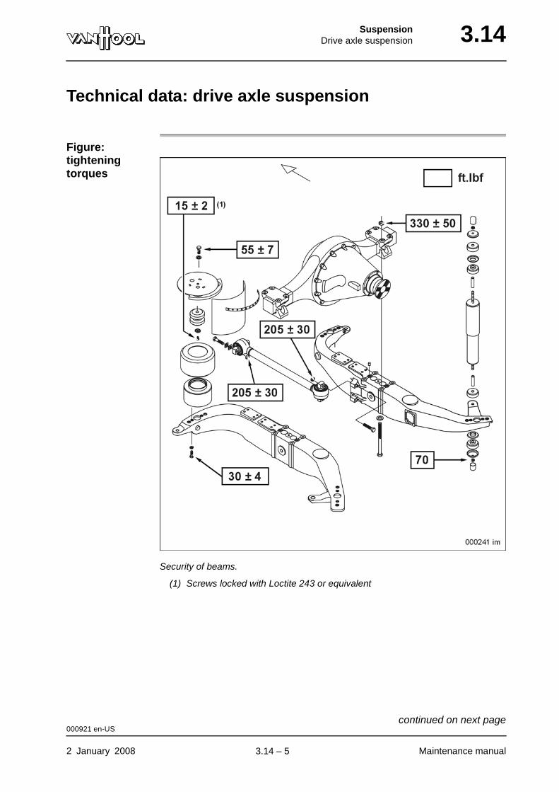
SuspensionDrive axle suspension 3.14
Technical data: drive axle suspension
Figure: tightening torques
Security of beams.
(1) Screws locked with Loctite 243 or equivalent
000921 en-US
2 January 2008 Maintenance manual
continued on next page.
3.14 – 5
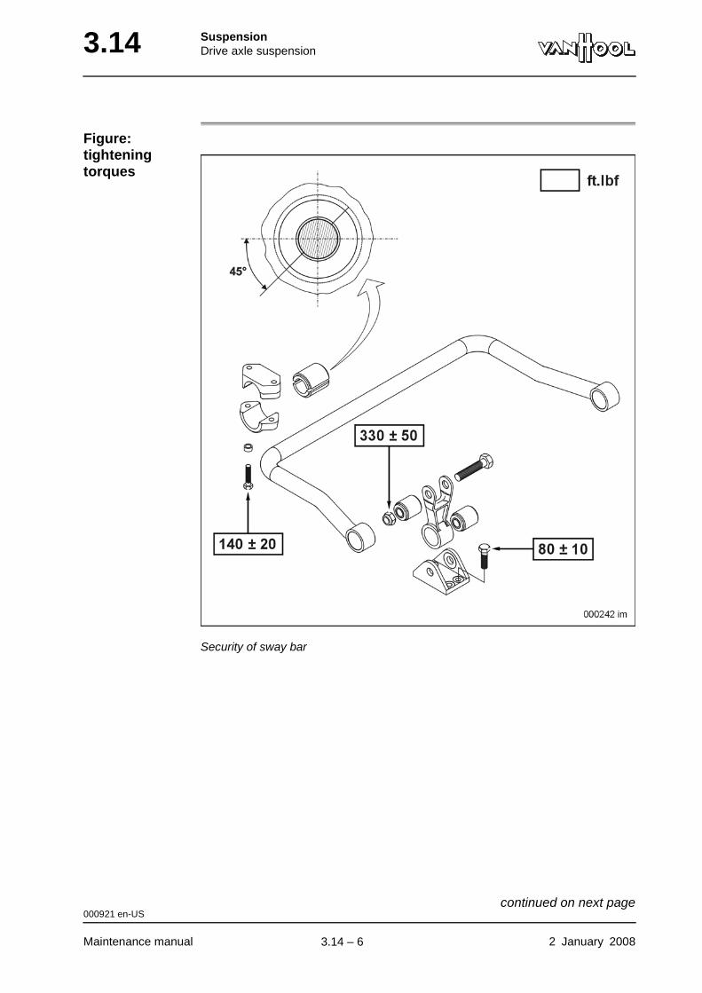
3.14 SuspensionDrive axle suspension
Figure: tightening torques
Security of sway bar
000921 en-US
Maintenance manual 2 January 2008
continued on next page.
3.14 – 6
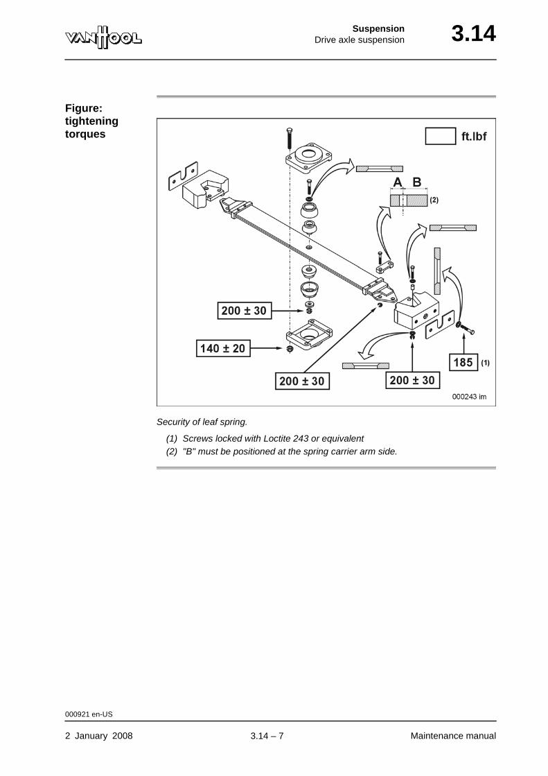
SuspensionDrive axle suspension 3.14
Figure: tightening torques
Security of leaf spring.
(1) Screws locked with Loctite 243 or equivalent(2) "B" must be positioned at the spring carrier arm side.
000921 en-US
2 January 2008 Maintenance manual
.
3.14 – 7
3.14 SuspensionDrive axle suspension
This page has been intentionally left blank.
000921 en-US
Maintenance manual 2 January 20083.14 – 8
SuspensionTrailing axle suspension 3.18
Chapter 18: Trailing axle suspension
Overview
Introduction This chapter deals with the trailing axle suspension.
Number of pages
4
Chapter publi-cation date
2 January 2008
Contents
Topic See page
To check security of suspension components 3.18-2
To check shock absorbers for damage and leakage 3.18-3
Technical data: trailing axle suspension 3.18-4
2 January 2008 Maintenance manual
.
3.18 – 1
3.18 SuspensionTrailing axle suspension
To check security of suspension components
Tightening torques
Refer to "Technical data" at the end of this chapter.
Procedure Visually check those bolts, screws and nuts that are locked by means of a cotter pin, a locking plate or locking adhesive (Loctite). The security of all others must be checked mechanically. Retighten, if necessary.
WARNING!Never retighten bolts, screws or nuts that are fitted with locking adhesive, as this would destroy locking properties.
003714 en-US
Maintenance manual 2 January 2008
.
3.18 – 2
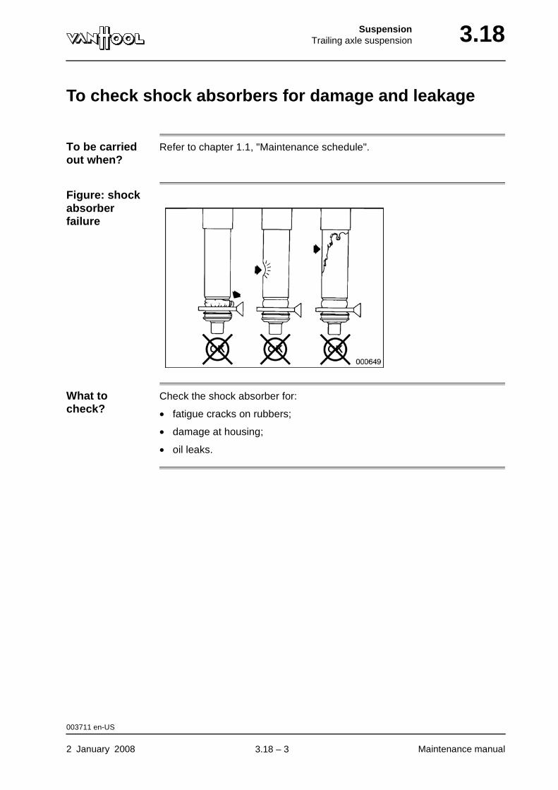
SuspensionTrailing axle suspension 3.18
To check shock absorbers for damage and leakage
To be carried out when?
Refer to chapter 1.1, "Maintenance schedule".
Figure: shock absorber failure
What to check?
Check the shock absorber for:
• fatigue cracks on rubbers;
• damage at housing;
• oil leaks.
003711 en-US
2 January 2008 Maintenance manual
.
3.18 – 3
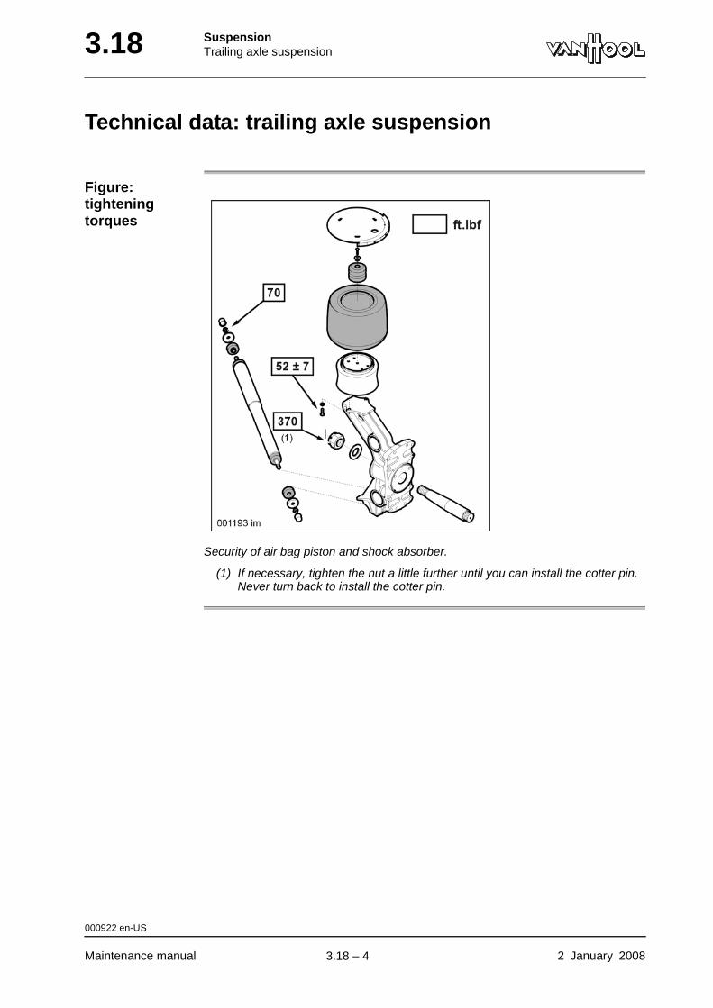
3.18 SuspensionTrailing axle suspension
Technical data: trailing axle suspension
Figure: tightening torques
Security of air bag piston and shock absorber.
(1) If necessary, tighten the nut a little further until you can install the cotter pin. Never turn back to install the cotter pin.
000922 en-US
Maintenance manual 2 January 2008
.
3.18 – 4
SuspensionWheels 3.34
Chapter 34: Wheels
Overview
Introduction This chapter deals with the wheels.
Number of pages
10
Chapter publi-cation date
2 January 2008
Contents
Topic See page
Wheel mounting systems 3.34-2
To change wheel 3.34-4
Technical data: wheels 3.34-7
Special tools: wheels 3.34-8
2 January 2008 Maintenance manual
.
3.34 – 1
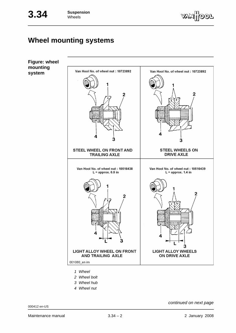
3.34 SuspensionWheels
Wheel mounting systems
Figure: wheel mounting system
1 Wheel2 Wheel bolt3 Wheel hub4 Wheel nut
000412 en-US
Maintenance manual 2 January 2008
continued on next page.
3.34 – 2
SuspensionWheels 3.34
Hub piloting Van Hoof applies the so-called "hub piloting" to its vehicles. the wheel disc center hole fits a machined spigot (or a number of pads) on the hub precisely.
Hub-piloting characteristics:
• Wheels with cylindrical bolt holes;
• Wheel nuts with flat, rotary but non-removable washers.
WARNING!Only use wheels and wheel nuts suitable for hub piloting.
000412 en-US
2 January 2008 Maintenance manual
.
3.34 – 3
3.34 SuspensionWheels
To change wheel
Wheel nut tightening torque
Refer to "Technical data" at the end of this chapter.
Precautions at wheel instal-lation
• Before mounting a wheel, remove burrs, rust, dirt and paint runs from the contact surfaces. These are the areas of the wheel disc that touch the hub (or the other wheel in a dubble assembly), as well as the wheel nut contact areas.
• The contact areas (see above) may only be painted very thinly. Total coat thickness may not exceed 0.002 in. Only mount the wheel after the paint has hardened completely. Too thick a coat of paint or wheel mounting, when the paint is not fully hard yet, can cause wheel nut slackening.
• Before installing a wheel, always check wheel bolts for damage. Also check that bolts are well-secured in hub bolt-holes.
• After fitting a new tire, the wheel has to be balanced again.
Procedure
Step Action
1 Using a socket wrench, remove the wheel nut caps, if present, by turning them counterclockwise until they are loose.
2 If necessary, clean wheel bolt ends with a stiff brush.
3 Slacken all wheel nuts by half a turn.
4 Jack up vehicle.
5 Remove wheel nuts and wheel.
000631 en-US
Maintenance manual 2 January 2008
continued on next page.
3.34 – 4
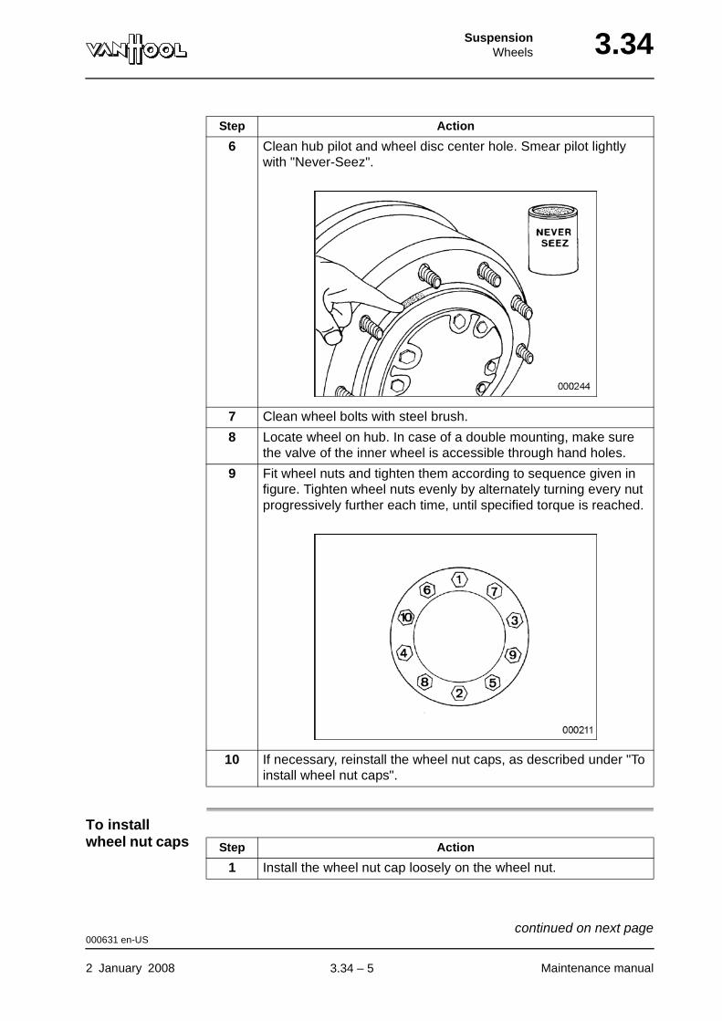
SuspensionWheels 3.34
To install wheel nut caps
6 Clean hub pilot and wheel disc center hole. Smear pilot lightly with "Never-Seez".
7 Clean wheel bolts with steel brush.
8 Locate wheel on hub. In case of a double mounting, make sure the valve of the inner wheel is accessible through hand holes.
9 Fit wheel nuts and tighten them according to sequence given in figure. Tighten wheel nuts evenly by alternately turning every nut progressively further each time, until specified torque is reached.
10 If necessary, reinstall the wheel nut caps, as described under "To install wheel nut caps".
Step Action
Step Action
1 Install the wheel nut cap loosely on the wheel nut.
000631 en-US
2 January 2008 Maintenance manual
continued on next page.
3.34 – 5
3.34 SuspensionWheels
To retighten wheel nuts
When a wheel has been changed, retighten wheel nuts with torque wrench after 30 miles and again after the next 60 miles. Subsequently check torque daily, until nuts are finally tight. Wheel nut slackening is explained by the fact that the fasteners set, so that part of the original torque is lost.
2
CAUTION!Only use a socket wrench to tighten the wheel nut caps.
Using a socket wrench, turn the wheel nut caps clockwise until you sense a slight clamping.
Step Action
000631 en-US
Maintenance manual 2 January 2008
.
3.34 – 6
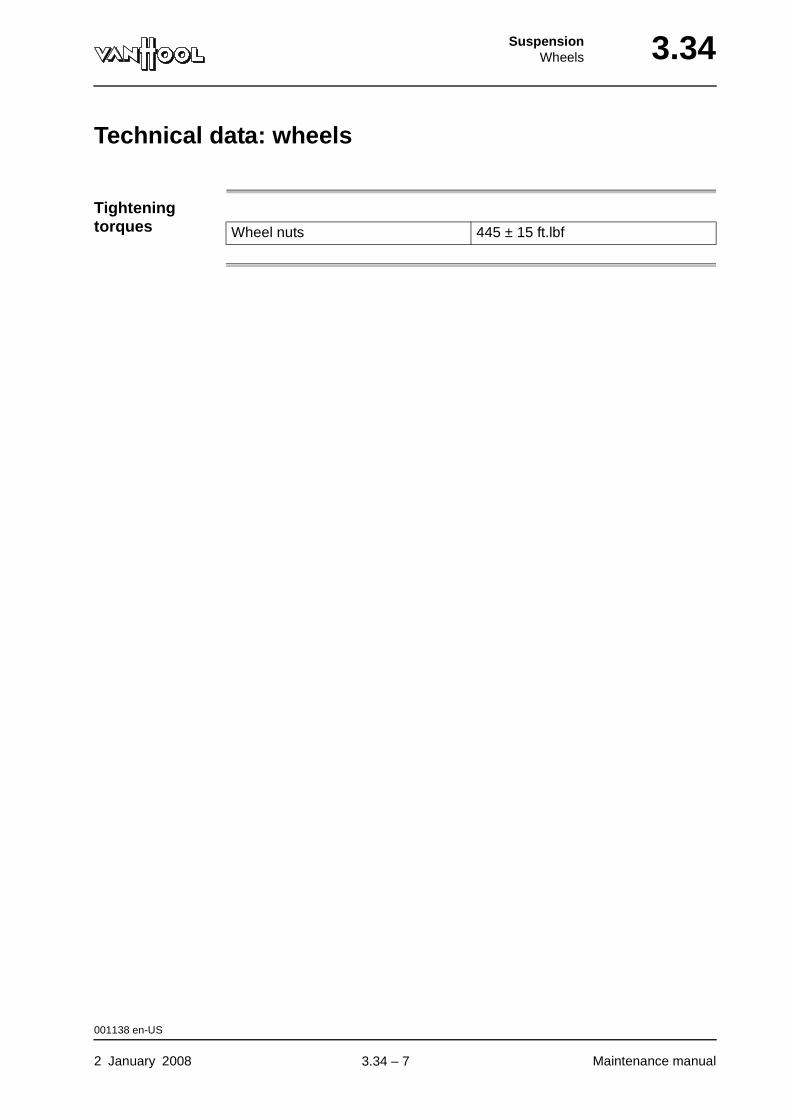
SuspensionWheels 3.34
Technical data: wheels
Tightening torques Wheel nuts 445 ± 15 ft.lbf
001138 en-US
2 January 2008 Maintenance manual
.
3.34 – 7

3.34 SuspensionWheels
Special tools: wheels
Ordering number Description Figure
Van Hool 619900160 Lifting bracket (for steel wheels)
Van Hool 10627455 Lifting bracket (for light alloy wheels)
Van Hool 10583382 Hydraulic jack
Van Hool 10581561 Wooden supporting block for jack
000789 en-US
Maintenance manual 2 January 2008
continued on next page.
3.34 – 8
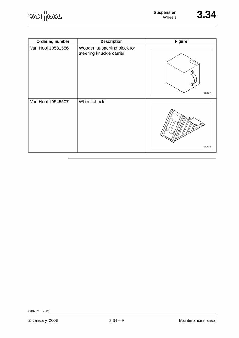
SuspensionWheels 3.34
Van Hool 10581556 Wooden supporting block for steering knuckle carrier
Van Hool 10545507 Wheel chock
Ordering number Description Figure
000789 en-US
2 January 2008 Maintenance manual
.
3.34 – 9
3.34 SuspensionWheels
This page has been intentionally left blank.
000789 en-US
Maintenance manual 2 January 20083.34 – 10
SuspensionTires 3.38
Chapter 38: Tires
Overview
Introduction This chapter deals with the tires.
Number of pages
8
Chapter publi-cation date
2 January 2008
Contents
Topic See page
Tire selection 3.38-2
To check tires for inflation pressure and damage 3.38-3
To inspect tires 3.38-4
What to check with dual tires? 3.38-6
To change tires 3.38-7
Technical data: tires 3.38-8
2 January 2008 Maintenance manual
.
3.38 – 1
3.38 SuspensionTires
Tire selection
WARNING!Do not fit tires of size or construction other than the original ones without prior consent by Van Hool. Never fit tires with lower load or speed ratings.
Dimensions Refer to "Technical data" at the end of this chapter.
Load and speed ratings
Refer to "Technical data" at the end of this chapter.
003746 en-US
Maintenance manual 2 January 2008
.
3.38 – 2
SuspensionTires 3.38
To check tires for inflation pressure and damage
To be carried out when?
Before commencing daily service.
Tire inflation pressure
Refer to "Technical data" at the end of this chapter.
CAUTION!If pressure is found to drop more than normal over a period of time, remove and inspect the tire to determine the cause.
Tire damage Remove any stones or similar which have become embedded in the tread. They may cause damage in the long run.
Change the tire, if you encounter any of the following signs of damage:
• bumps, bulges or knots;
• tread cuts, snags or side wall cracks deep enough to expose the casing cords;
• any exposed casing material.
003748 en-US
2 January 2008 Maintenance manual
.
3.38 – 3
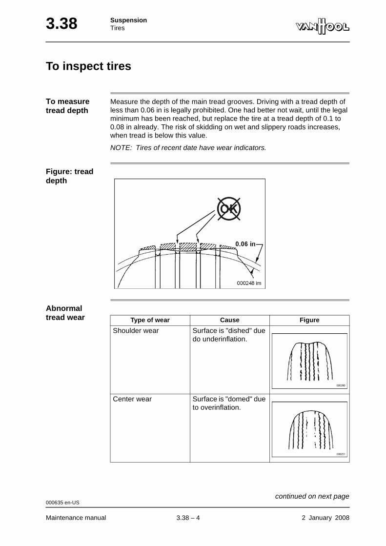
3.38 SuspensionTires
To inspect tires
To measure tread depth
Measure the depth of the main tread grooves. Driving with a tread depth of less than 0.06 in is legally prohibited. One had better not wait, until the legal minimum has been reached, but replace the tire at a tread depth of 0.1 to 0.08 in already. The risk of skidding on wet and slippery roads increases, when tread is below this value.
NOTE: Tires of recent date have wear indicators.
Figure: tread depth
Abnormal tread wear Type of wear Cause Figure
Shoulder wear Surface is "dished" due do underinflation.
Center wear Surface is "domed" due to overinflation.
000635 en-US
Maintenance manual 2 January 2008
continued on next page.
3.38 – 4
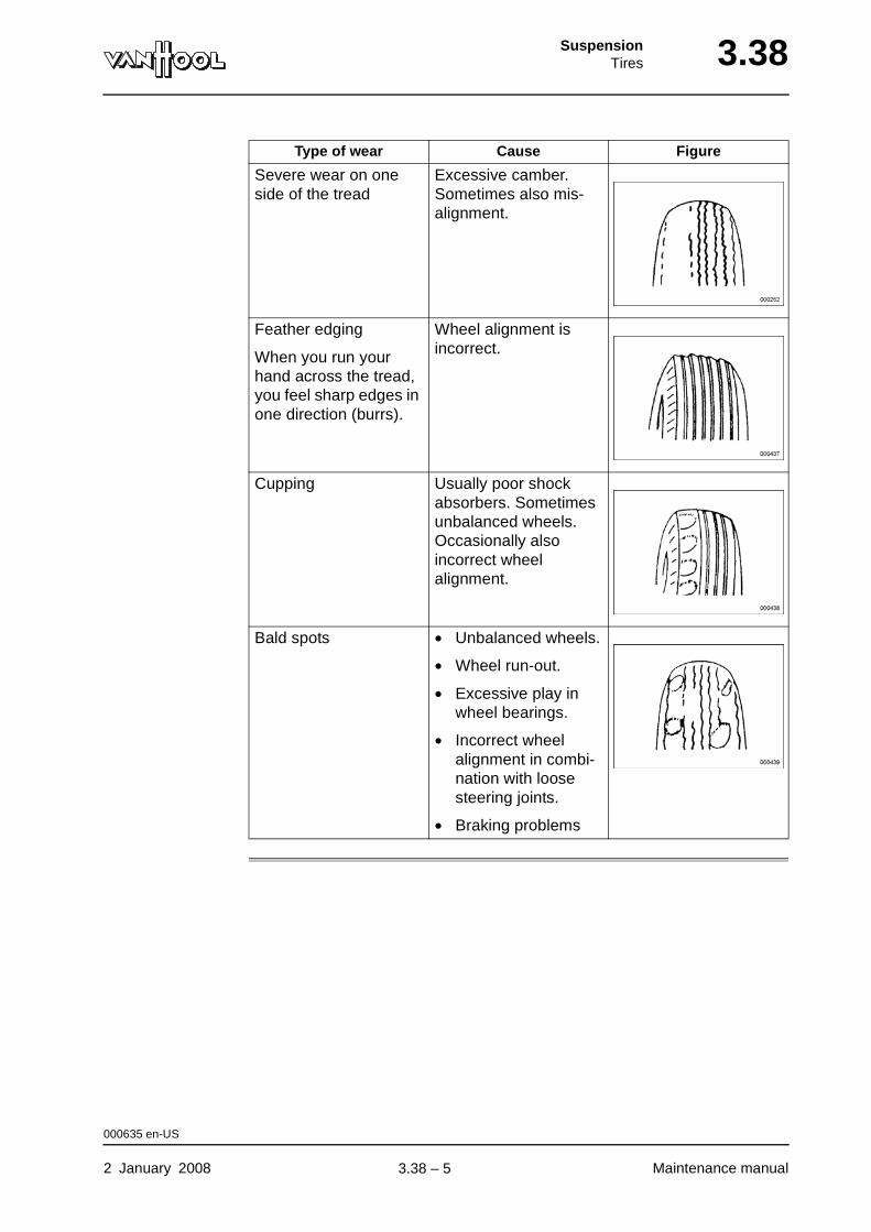
SuspensionTires 3.38
Severe wear on one side of the tread
Excessive camber. Sometimes also mis-alignment.
Feather edging
When you run your hand across the tread, you feel sharp edges in one direction (burrs).
Wheel alignment is incorrect.
Cupping Usually poor shock absorbers. Sometimes unbalanced wheels. Occasionally also incorrect wheel alignment.
Bald spots • Unbalanced wheels.
• Wheel run-out.
• Excessive play in wheel bearings.
• Incorrect wheel alignment in combi-nation with loose steering joints.
• Braking problems
Type of wear Cause Figure
000635 en-US
2 January 2008 Maintenance manual
.
3.38 – 5
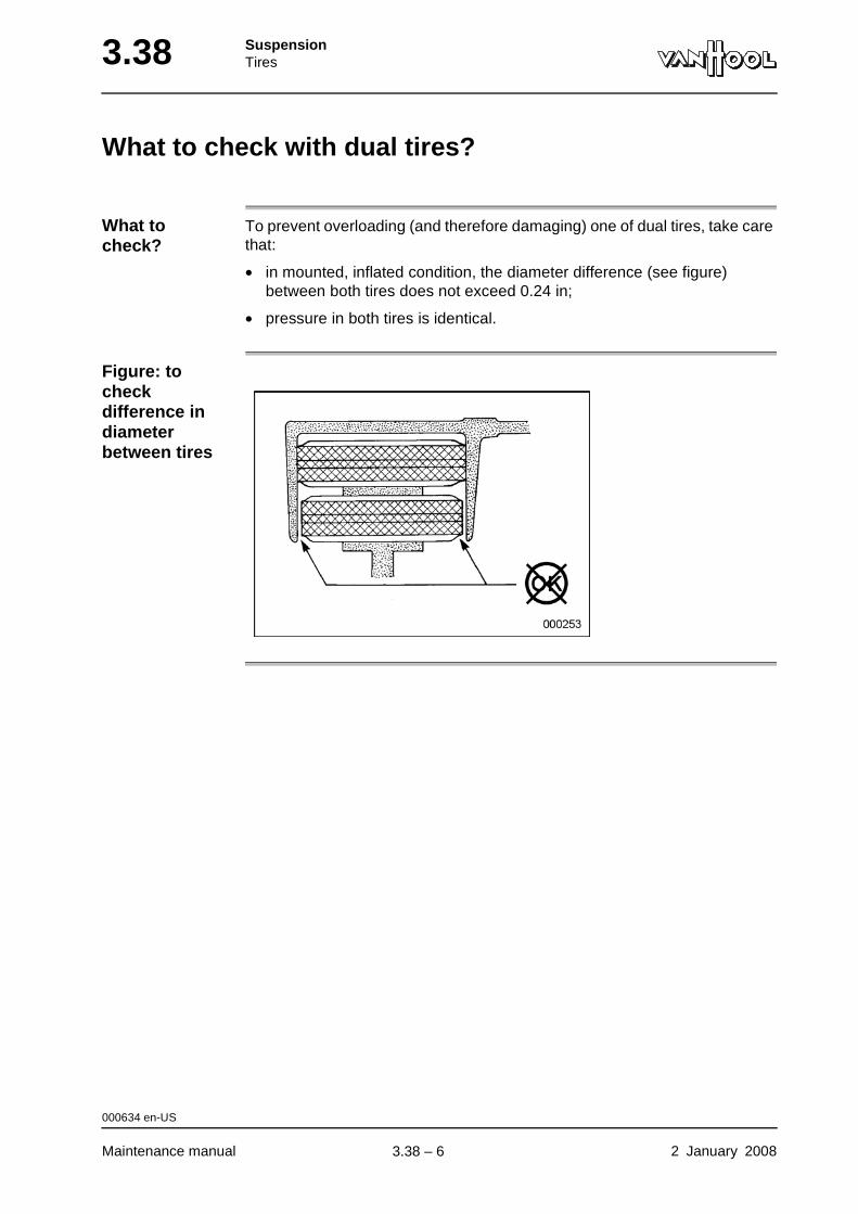
3.38 SuspensionTires
What to check with dual tires?
What to check?
To prevent overloading (and therefore damaging) one of dual tires, take care that:
• in mounted, inflated condition, the diameter difference (see figure) between both tires does not exceed 0.24 in;
• pressure in both tires is identical.
Figure: to check difference in diameter between tires
000634 en-US
Maintenance manual 2 January 2008
.
3.38 – 6
SuspensionTires 3.38
To change tires
To remove/mount tires
To change a tire on this vehicle, follow the normal procedure for tubeless tires and drop-center rims.
NOTE: Always change the tires on each side of the axle at the same time.
000011 en-US
2 January 2008 Maintenance manual
.
3.38 – 7
3.38 SuspensionTires
Technical data: tires
Which tires should be on the vehicle?
Tire inflation pressure
The tire inflation pressure is mentioned on the vehicle identification plate in the step well of the passenger door.
The pressure values given in the table apply to cold tires, i.e. after at least 1 hour of standstill.
Under extreme operating conditions or, if tire wear gives cause to do so, tire inflation pressure should be adapted after consulting the tire manufacturer and Van Hool.
Dimensions Load and speed ratings
315/80 R22.5 156/150 L
004147 en-US
Maintenance manual 2 January 2008
.
3.38 – 8

Part 4 - Driveline/Axle
Overview
Contents
Chapter See page
Chapter 10: Propeller shaft 4.10-1

Driveline/AxlePropeller shaft 4.10
Chapter 10: Propeller shaft
Overview
Introduction This chapter deals with the propeller shaft.
Number of pages
14
Chapter publi-cation date
2 January 2008
Contents
Topic See page
To carry out minor inspection of propeller shaft 4.10-2
To lubricate propeller shaft universal joints 4.10-7
To carry out major inspection of propeller shaft 4.10-8
To install propeller shaft 4.10-11
Technical data: propeller shaft 4.10-13
2 January 2008 Maintenance manual
.
4.10 – 1
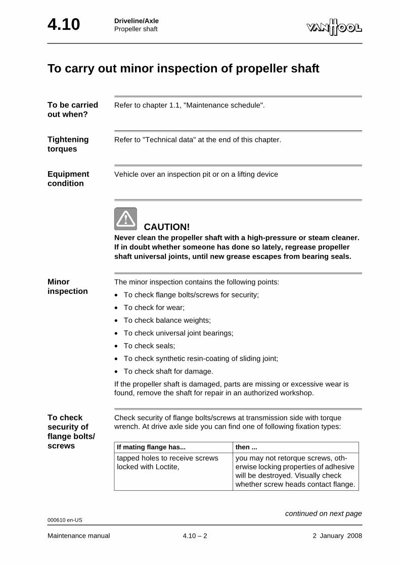
4.10 Driveline/AxlePropeller shaft
To carry out minor inspection of propeller shaft
To be carried out when?
Refer to chapter 1.1, "Maintenance schedule".
Tightening torques
Refer to "Technical data" at the end of this chapter.
Equipment condition
Vehicle over an inspection pit or on a lifting device
CAUTION!Never clean the propeller shaft with a high-pressure or steam cleaner. If in doubt whether someone has done so lately, regrease propeller shaft universal joints, until new grease escapes from bearing seals.
Minor inspection
The minor inspection contains the following points:
• To check flange bolts/screws for security;
• To check for wear;
• To check balance weights;
• To check universal joint bearings;
• To check seals;
• To check synthetic resin-coating of sliding joint;
• To check shaft for damage.
If the propeller shaft is damaged, parts are missing or excessive wear is found, remove the shaft for repair in an authorized workshop.
To check security of flange bolts/screws
Check security of flange bolts/screws at transmission side with torque wrench. At drive axle side you can find one of following fixation types:
If mating flange has... then ...
tapped holes to receive screws locked with Loctite,
you may not retorque screws, oth-erwise locking properties of adhesive will be destroyed. Visually check whether screw heads contact flange.
000610 en-US
Maintenance manual 2 January 2008
continued on next page.
4.10 – 2
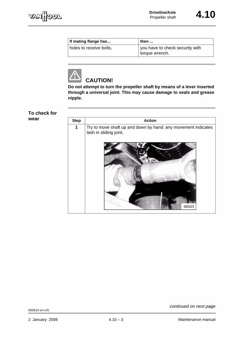
Driveline/AxlePropeller shaft 4.10
CAUTION!Do not attempt to turn the propeller shaft by means of a lever inserted through a universal joint. This may cause damage to seals and grease nipple.
To check for wear
holes to receive bolts, you have to check security with torque wrench.
If mating flange has... then ...
Step Action
1 Try to move shaft up and down by hand: any movement indicates lash in sliding joint.
000610 en-US
2 January 2008 Maintenance manual
continued on next page.
4.10 – 3
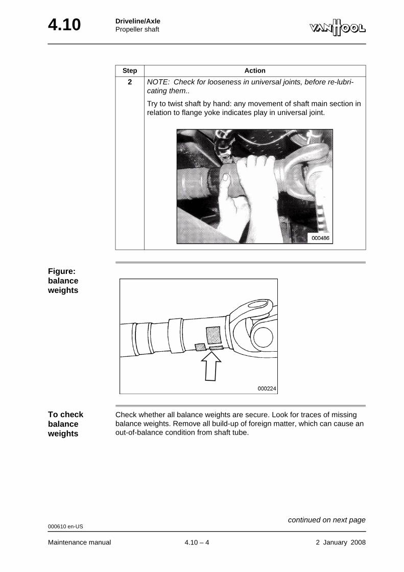
4.10 Driveline/AxlePropeller shaft
Figure: balance weights
To check balance weights
Check whether all balance weights are secure. Look for traces of missing balance weights. Remove all build-up of foreign matter, which can cause an out-of-balance condition from shaft tube.
2 NOTE: Check for looseness in universal joints, before re-lubri-cating them..
Try to twist shaft by hand: any movement of shaft main section in relation to flange yoke indicates play in universal joint.
Step Action
000610 en-US
Maintenance manual 2 January 2008
continued on next page.
4.10 – 4
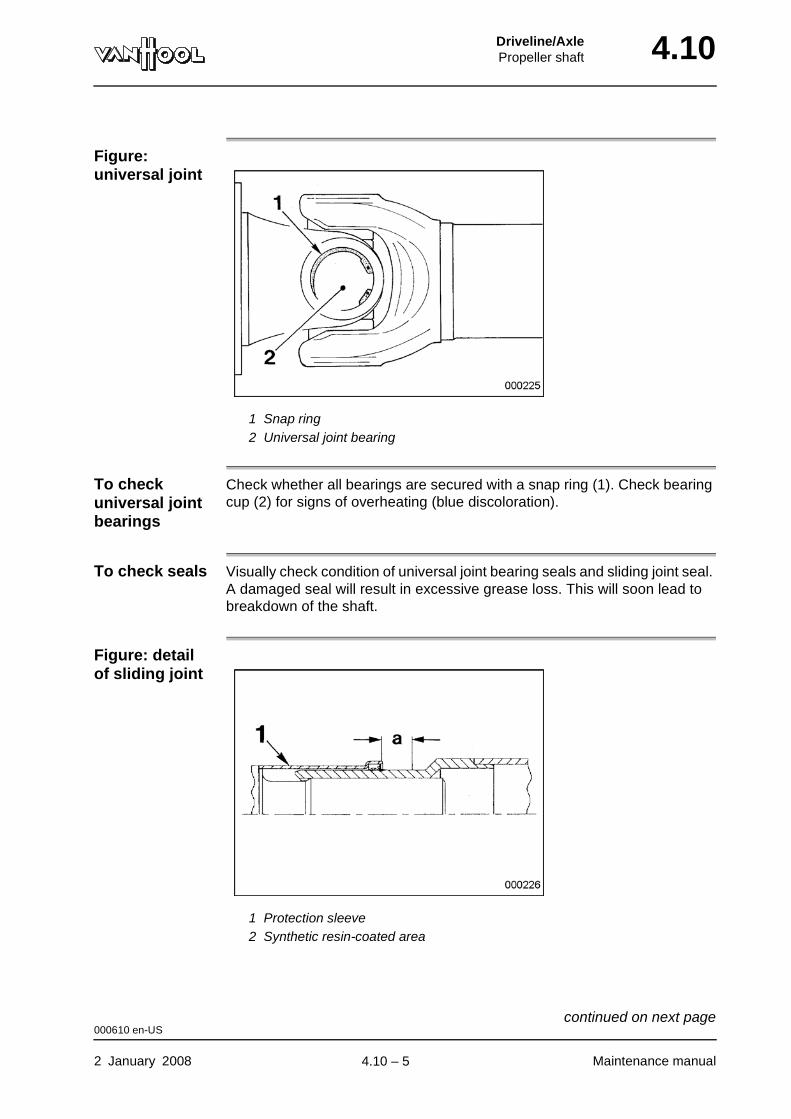
Driveline/AxlePropeller shaft 4.10
Figure: universal joint
1 Snap ring2 Universal joint bearing
To check universal joint bearings
Check whether all bearings are secured with a snap ring (1). Check bearing cup (2) for signs of overheating (blue discoloration).
To check seals Visually check condition of universal joint bearing seals and sliding joint seal. A damaged seal will result in excessive grease loss. This will soon lead to breakdown of the shaft.
Figure: detail of sliding joint
1 Protection sleeve2 Synthetic resin-coated area
000610 en-US
2 January 2008 Maintenance manual
continued on next page.
4.10 – 5
4.10 Driveline/AxlePropeller shaft
To check synthetic resin-coating
Check condition of synthetic resin-coating at outer diameter of slip stub shaft (where protective sleeve seal will slide). The coating may not show signs of any damage or abrasion.
To check shaft for damage
Visually check shaft tube for flaked paint, cracks and dents. Also check pro-tection sleeve (1) of sliding joint for eccentricity.
000610 en-US
Maintenance manual 2 January 2008
.
4.10 – 6
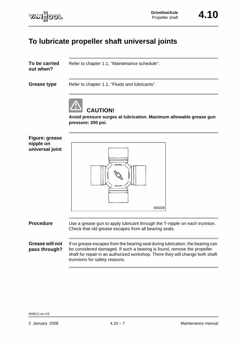
Driveline/AxlePropeller shaft 4.10
To lubricate propeller shaft universal joints
To be carried out when?
Refer to chapter 1.1, "Maintenance schedule".
Grease type Refer to chapter 1.1, "Fluids and lubricants".
CAUTION!Avoid pressure surges at lubrication. Maximum allowable grease gun pressure: 200 psi.
Figure: grease nipple on universal joint
Procedure Use a grease gun to apply lubricant through the T-nipple on each trunnion. Check that old grease escapes from all bearing seals.
Grease will not pass through?
If no grease escapes from the bearing seal during lubrication, the bearing can be considered damaged. If such a bearing is found, remove the propeller shaft for repair in an authorized workshop. There they will change both shaft trunnions for safety reasons.
000612 en-US
2 January 2008 Maintenance manual
.
4.10 – 7
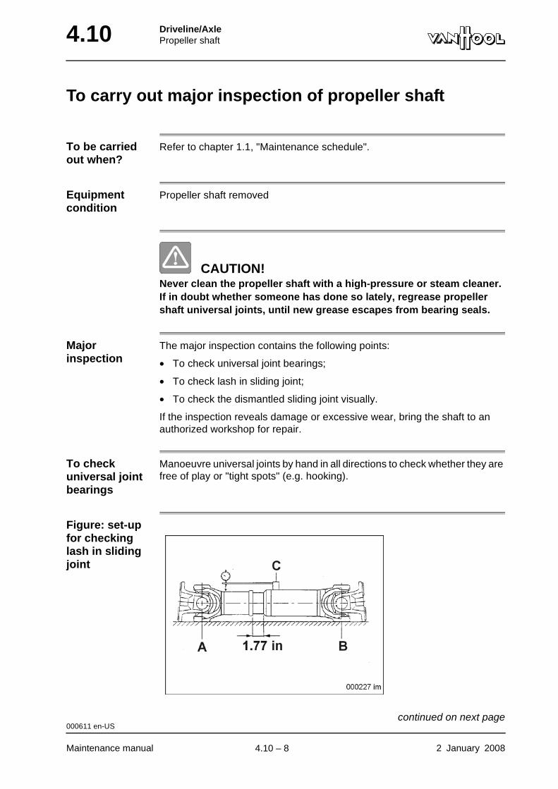
4.10 Driveline/AxlePropeller shaft
To carry out major inspection of propeller shaft
To be carried out when?
Refer to chapter 1.1, "Maintenance schedule".
Equipment condition
Propeller shaft removed
CAUTION!Never clean the propeller shaft with a high-pressure or steam cleaner. If in doubt whether someone has done so lately, regrease propeller shaft universal joints, until new grease escapes from bearing seals.
Major inspection
The major inspection contains the following points:
• To check universal joint bearings;
• To check lash in sliding joint;
• To check the dismantled sliding joint visually.
If the inspection reveals damage or excessive wear, bring the shaft to an authorized workshop for repair.
To check universal joint bearings
Manoeuvre universal joints by hand in all directions to check whether they are free of play or "tight spots" (e.g. hooking).
Figure: set-up for checking lash in sliding joint
000611 en-US
Maintenance manual 2 January 2008
continued on next page.
4.10 – 8
Driveline/AxlePropeller shaft 4.10
To check lash in sliding joint
To check dismantled sliding joint
Step Action
1 Lay complete shaft on flat surface, lugs of inner yokes resting on surface (points A and B). Extend sliding joint by approximately 1.77 in.
2 Mount dial indicator with magnetic base next to weld of sliding yoke (point C). Position stylus of dial indicator against protective sleeve, as close as possible to weld of latter.
3 Lift propeller shaft (approximately in its center of gravity), until inner yokes become free of flat surface.
4 Read variation shown by dial indicator.
The maximum allowable value is 0.0067 in.
Step Action
1
CAUTION!Do not damage synthetic coating of sliding joint. Do not use solvents; they can affect the synthetic coating.
Withdraw slip stub shaft from sliding yoke.
2 Examine sliding joint for damage on inside and outside of sliding yoke ant at splines of slip stub shaft.
3 Check condition of protective sleeve seal.
4 If sliding joint is undamaged, regrease splines and seal.
For grease type refer to chapter 1.1, "Fluids and lubricants".
000611 en-US
2 January 2008 Maintenance manual
continued on next page.
4.10 – 9
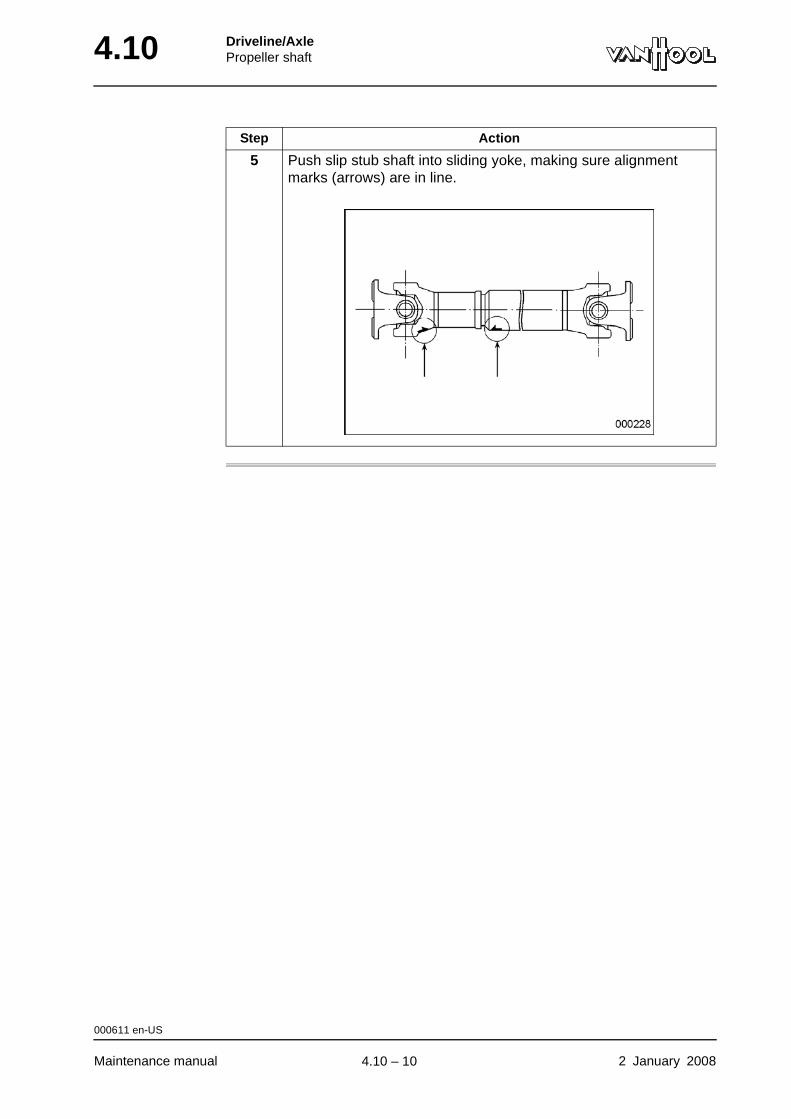
4.10 Driveline/AxlePropeller shaft
5 Push slip stub shaft into sliding yoke, making sure alignment marks (arrows) are in line.
Step Action
000611 en-US
Maintenance manual 2 January 2008
.
4.10 – 10
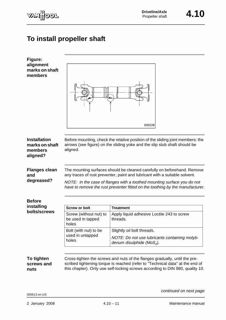
Driveline/AxlePropeller shaft 4.10
To install propeller shaft
Figure: alignment marks on shaft members
Installation marks on shaft members aligned?
Before mounting, check the relative position of the sliding joint members: the arrows (see figure) on the sliding yoke and the slip stub shaft should be aligned.
Flanges clean and degreased?
The mounting surfaces should be cleaned carefully on beforehand. Remove any traces of rust preventer, paint and lubricant with a suitable solvent.
NOTE: In the case of flanges with a toothed mounting surface you do not have to remove the rust preventer fitted on the toothing by the manufacturer.
Before installing bolts/screws
To tighten screws and nuts
Cross-tighten the screws and nuts of the flanges gradually, until the pre-scribed tightening torque is reached (refer to "Technical data" at the end of this chapter). Only use self-locking screws according to DIN 980, quality 10.
Screw or bolt Treatment
Screw (without nut) to be used in tapped holes
Apply liquid adhesive Loctite 243 to screw threads.
Bolt (with nut) to be used in untapped holes
Slightly oil bolt threads.
NOTE: Do not use lubricants containing molyb-denum disulphide (MoS2).
000613 en-US
2 January 2008 Maintenance manual
continued on next page.
4.10 – 11

4.10 Driveline/AxlePropeller shaft
Figure: detail of sliding joint
1 Protection sleevea Synthetic resin-coated area
When painting During painting operations the synthetic resin-coated plain section of the sliding yoke, where the protective sleeve seal will slide, has to be protected.
000613 en-US
Maintenance manual 2 January 2008
.
4.10 – 12
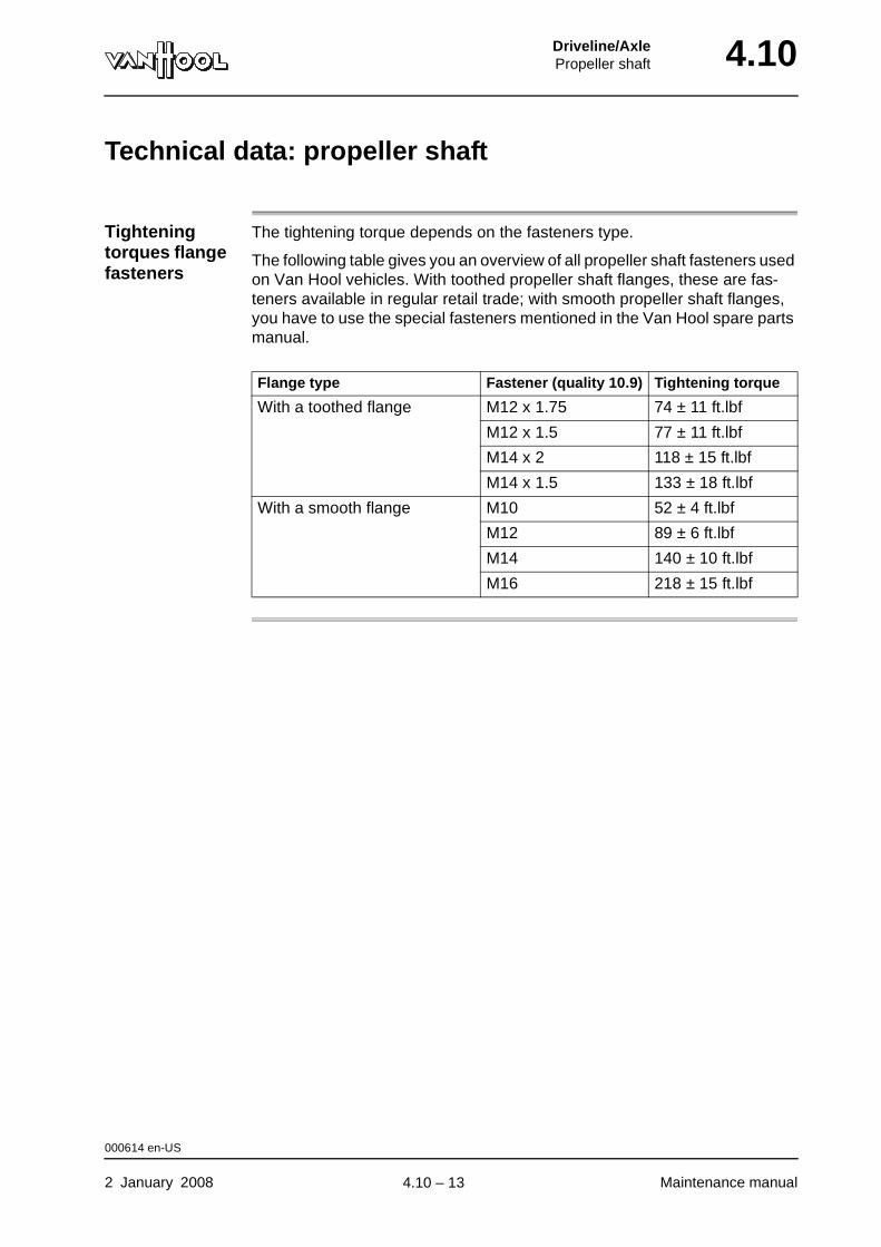
Driveline/AxlePropeller shaft 4.10
Technical data: propeller shaft
Tightening torques flange fasteners
The tightening torque depends on the fasteners type.
The following table gives you an overview of all propeller shaft fasteners used on Van Hool vehicles. With toothed propeller shaft flanges, these are fas-teners available in regular retail trade; with smooth propeller shaft flanges, you have to use the special fasteners mentioned in the Van Hool spare parts manual.
Flange type Fastener (quality 10.9) Tightening torque
With a toothed flange M12 x 1.75 74 ± 11 ft.lbf
M12 x 1.5 77 ± 11 ft.lbf
M14 x 2 118 ± 15 ft.lbf
M14 x 1.5 133 ± 18 ft.lbf
With a smooth flange M10 52 ± 4 ft.lbf
M12 89 ± 6 ft.lbf
M14 140 ± 10 ft.lbf
M16 218 ± 15 ft.lbf
000614 en-US
2 January 2008 Maintenance manual
.
4.10 – 13
4.10 Driveline/AxlePropeller shaft
This page has been intentionally left blank.
000614 en-US
Maintenance manual 2 January 20084.10 – 14
Part 5 - Brakes
Overview
Contents
Chapter See page
Chapter 2: Control systems 5.2-1
Chapter 10: Compressed-air brakes 5.10-1
Chapter 14: Retarder 5.14-1

BrakesControl systems 5.2
Chapter 2: Control systems
Overview
Introduction This chapter deals with the control systems.
Number of pages
22
Chapter publi-cation date
14 November 2008
Contents
Topic See page
ABS: visual identification of components 5.2-2
ABS: fault reproduction 5.2-3
ABS: troubleshooting with diagnostic switch 5.2-5
To test ABS with "Pro-Link" or "Toolbox Software" 5.2-9
ABS: control unit versions 5.2-10
ABS: to check power supply 5.2-12
To check ABS valve 5.2-13
To check ABS wheel-speed sensor 5.2-17
To install ABS wheel-speed sensor 5.2-21
14 November 2008 Maintenance manual
.
5.2 – 1
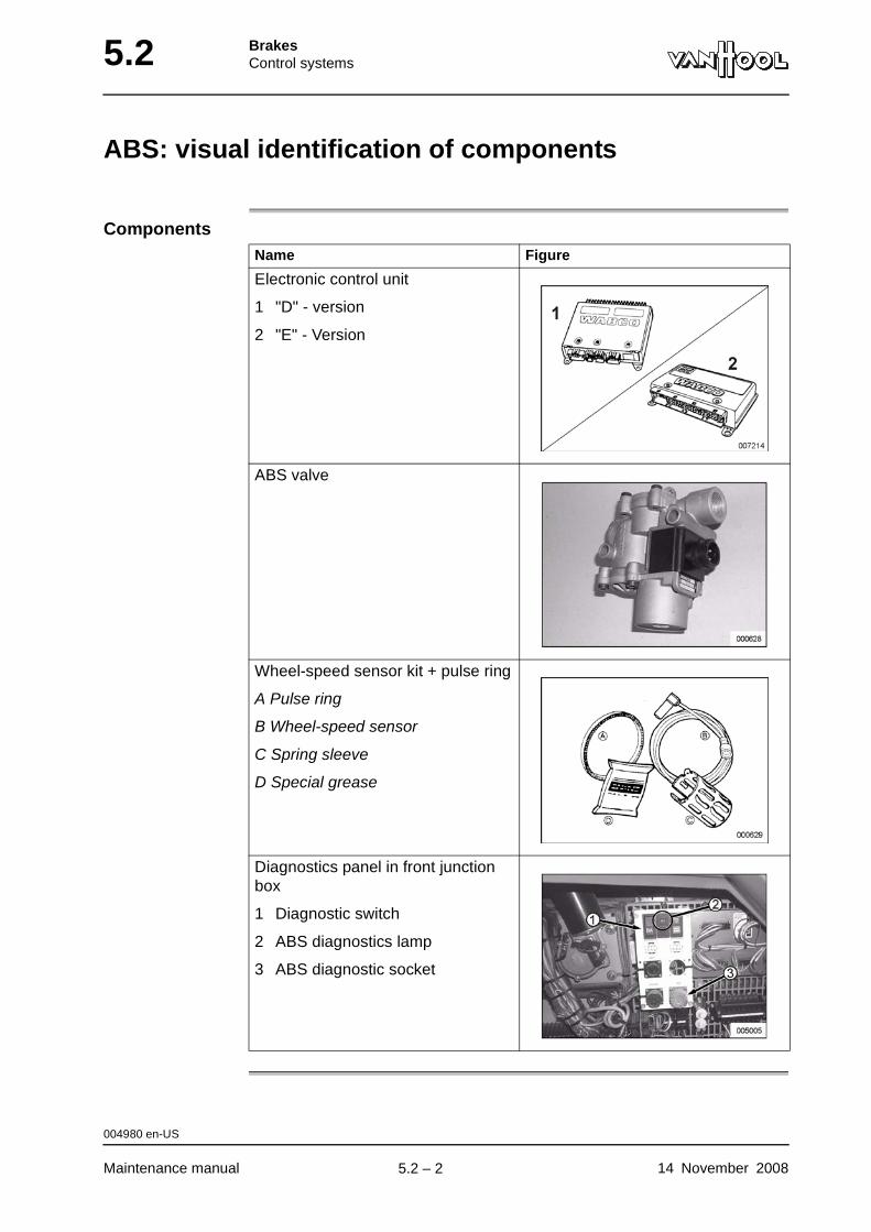
5.2 BrakesControl systems
ABS: visual identification of components
ComponentsName Figure
Electronic control unit
1 "D" - version
2 "E" - Version
ABS valve
Wheel-speed sensor kit + pulse ring
A Pulse ring
B Wheel-speed sensor
C Spring sleeve
D Special grease
Diagnostics panel in front junction box
1 Diagnostic switch
2 ABS diagnostics lamp
3 ABS diagnostic socket
004980 en-US
Maintenance manual 14 November 2008
.
5.2 – 2

BrakesControl systems 5.2
ABS: fault reproduction
Introduction The electronic control unit contains a self-diagnostic feature. The electronics constantly monitor the correct operation of the system and fault findings are stored in a memory. Upon request, the ABS lamp on the diagnostic panel in the front junction box shows fault memory contents in the form of a flash code.
What does a flash code look like?
The fault code consists of two sets of flashes with each set separated by a 1.5 seconds pause.
If there are more fault findings in the memory, their flash codes are separated by a 4 seconds pause.
Figure: example of fault codes
Fault codes 3-2 and 2-2
Types of faultsType of fault What is it?
Active fault • Fault that exists during the reading of the diagnostic memory
NOTE: An active fault must be repaired, before you can display additional faults.
Stored fault • A repaired fault that has not been cleared from the diagnostic memory, or...
• a fault that has disappeared spontaneously.
004981 en-US
14 November 2008 Maintenance manual
continued on next page.
5.2 – 3

5.2 BrakesControl systems
Fault repro-duction according to fault type
The reproduction of the fault code is different for "active" and for "stored" faults.
In the case of... the diagnostic lamp displays... and...
an active fault one fault code, even if there are more fault messages in the memory
repeats this code, as long as vehicle ignition is switched on.
a stored fault successively the codes of all stored fault messages
does this one time only.
NOTE: If you want to look at the codes again, press the diag-nostic push-button a second time.
004981 en-US
Maintenance manual 14 November 2008
.
5.2 – 4
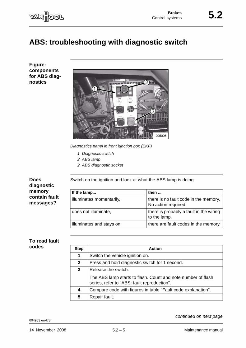
BrakesControl systems 5.2
ABS: troubleshooting with diagnostic switch
Figure: components for ABS diag-nostics
Diagnostics panel in front junction box (EKF)
1 Diagnostic switch2 ABS lamp2 ABS diagnostic socket
Does diagnostic memory contain fault messages?
Switch on the ignition and look at what the ABS lamp is doing.
To read fault codes
If the lamp... then ...
illuminates momentarily, there is no fault code in the memory. No action required.
does not illuminate, there is probably a fault in the wiring to the lamp.
illuminates and stays on, there are fault codes in the memory.
Step Action
1 Switch the vehicle ignition on.
2 Press and hold diagnostic switch for 1 second.
3 Release the switch.
The ABS lamp starts to flash. Count and note number of flash series, refer to "ABS: fault reproduction".
4 Compare code with figures in table "Fault code explanation".
5 Repair fault.
004983 en-US
14 November 2008 Maintenance manual
continued on next page.
5.2 – 5
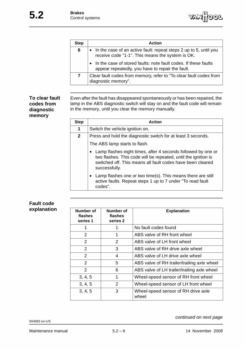
5.2 BrakesControl systems
To clear fault codes from diagnostic memory
Even after the fault has disappeared spontaneously or has been repaired, the lamp in the ABS diagnostic switch will stay on and the fault code will remain in the memory, until you clear the memory manually.
Fault code explanation
6 • In the case of an active fault: repeat steps 2 up to 5, until you receive code "1-1". This means the system is OK.
• In the case of stored faults: note fault codes. If these faults appear repeatedly, you have to repair the fault.
7 Clear fault codes from memory, refer to "To clear fault codes from diagnostic memory".
Step Action
Step Action
1 Switch the vehicle ignition on.
2 Press and hold the diagnostic switch for at least 3 seconds.
The ABS lamp starts to flash.
• Lamp flashes eight times, after 4 seconds followed by one or two flashes. This code will be repeated, until the ignition is switched off. This means all fault codes have been cleared successfully.
• Lamp flashes one or two time(s). This means there are still active faults. Repeat steps 1 up to 7 under "To read fault codes".
Number of flashes series 1
Number of flashes series 2
Explanation
1 1 No fault codes found
2 1 ABS valve of RH front wheel
2 2 ABS valve of LH front wheel
2 3 ABS valve of RH drive axle wheel
2 4 ABS valve of LH drive axle wheel
2 5 ABS valve of RH trailer/trailing axle wheel
2 6 ABS valve of LH trailer/trailing axle wheel
3, 4, 5 1 Wheel-speed sensor of RH front wheel
3, 4, 5 2 Wheel-speed sensor of LH front wheel
3, 4, 5 3 Wheel-speed sensor of RH drive axle wheel
004983 en-US
Maintenance manual 14 November 2008
continued on next page.
5.2 – 6
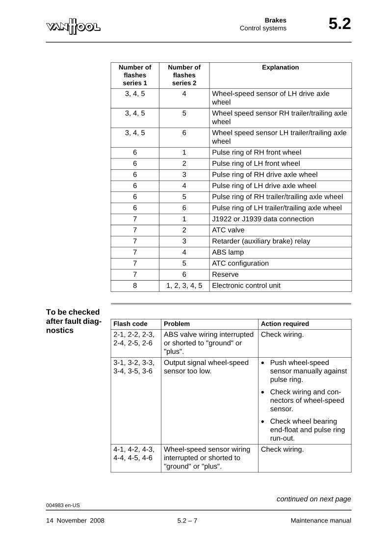
BrakesControl systems 5.2
To be checked after fault diag-nostics
3, 4, 5 4 Wheel-speed sensor of LH drive axle wheel
3, 4, 5 5 Wheel speed sensor RH trailer/trailing axle wheel
3, 4, 5 6 Wheel speed sensor LH trailer/trailing axle wheel
6 1 Pulse ring of RH front wheel
6 2 Pulse ring of LH front wheel
6 3 Pulse ring of RH drive axle wheel
6 4 Pulse ring of LH drive axle wheel
6 5 Pulse ring of RH trailer/trailing axle wheel
6 6 Pulse ring of LH trailer/trailing axle wheel
7 1 J1922 or J1939 data connection
7 2 ATC valve
7 3 Retarder (auxiliary brake) relay
7 4 ABS lamp
7 5 ATC configuration
7 6 Reserve
8 1, 2, 3, 4, 5 Electronic control unit
Number of flashes series 1
Number of flashes series 2
Explanation
Flash code Problem Action required
2-1, 2-2, 2-3, 2-4, 2-5, 2-6
ABS valve wiring interrupted or shorted to "ground" or "plus".
Check wiring.
3-1, 3-2, 3-3, 3-4, 3-5, 3-6
Output signal wheel-speed sensor too low.
• Push wheel-speed sensor manually against pulse ring.
• Check wiring and con-nectors of wheel-speed sensor.
• Check wheel bearing end-float and pulse ring run-out.
4-1, 4-2, 4-3, 4-4, 4-5, 4-6
Wheel-speed sensor wiring interrupted or shorted to "ground" or "plus".
Check wiring.
004983 en-US
14 November 2008 Maintenance manual
continued on next page.
5.2 – 7

5.2 BrakesControl systems
5-1, 5-2, 5-3, 5-4, 5-5, 5-6
Output signal of wheel-speed sensor irregular.
• Check wiring and con-nectors of wheel-speed sensor.
• Check pulse ring for damage.
6-1, 6-2, 6-3, 6-4, 6-5, 6-6
Check pulse ring for damage.
7-1 Contact Van Hool or an ArvinMeritor agent.
7-2 ATC valve wiring interrupted or shorted to "ground" or "plus".
Check wiring.
7-3 Check wiring to retarder.
7-4 Check the ABS lamp wiring
7-5 Contact Van Hool or an ArvinMeritor agent.
7-6 Output interrupted, or shorted to "ground" or "plus"
Check wiring.
8-1 Power supply sometimes too low
Check power supply and fuses.
8-2 Power supply longer than 5 seconds too high
Check power supply.
8-3 Change electronic control unit, if fault occurs repeatedly.
8-4 Contact Van Hool or an ArvinMeritor agent.
8-5 Check ground connections of electronic control unit and common valve wires.
Flash code Problem Action required
004983 en-US
Maintenance manual 14 November 2008
.
5.2 – 8

BrakesControl systems 5.2
To test ABS with "Pro-Link" or "Toolbox Software"
Cross-reference
NOTE: The maintenance manuals below are available through "www.meri-torwabco.com".
• "D" version control unit: refer to maintenance manual MM-30 by Meritor-Wabco.
• "E" version control unit: refer to maintenance manual MM-0112 by Meri-torWabco.
007772 en-US
14 November 2008 Maintenance manual
.
5.2 – 9
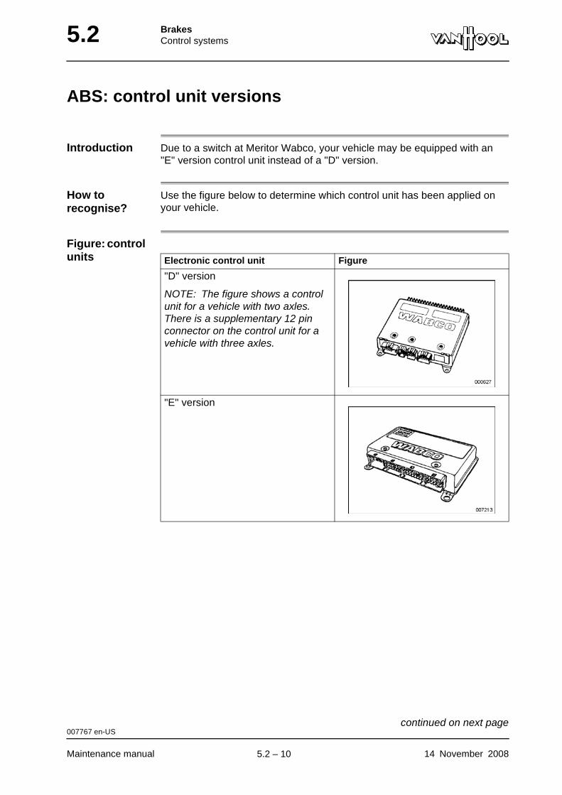
5.2 BrakesControl systems
ABS: control unit versions
Introduction Due to a switch at Meritor Wabco, your vehicle may be equipped with an "E" version control unit instead of a "D" version.
How to recognise?
Use the figure below to determine which control unit has been applied on your vehicle.
Figure: control units Electronic control unit Figure
"D" version
NOTE: The figure shows a control unit for a vehicle with two axles. There is a supplementary 12 pin connector on the control unit for a vehicle with three axles.
"E" version
007767 en-US
Maintenance manual 14 November 2008
continued on next page.
5.2 – 10
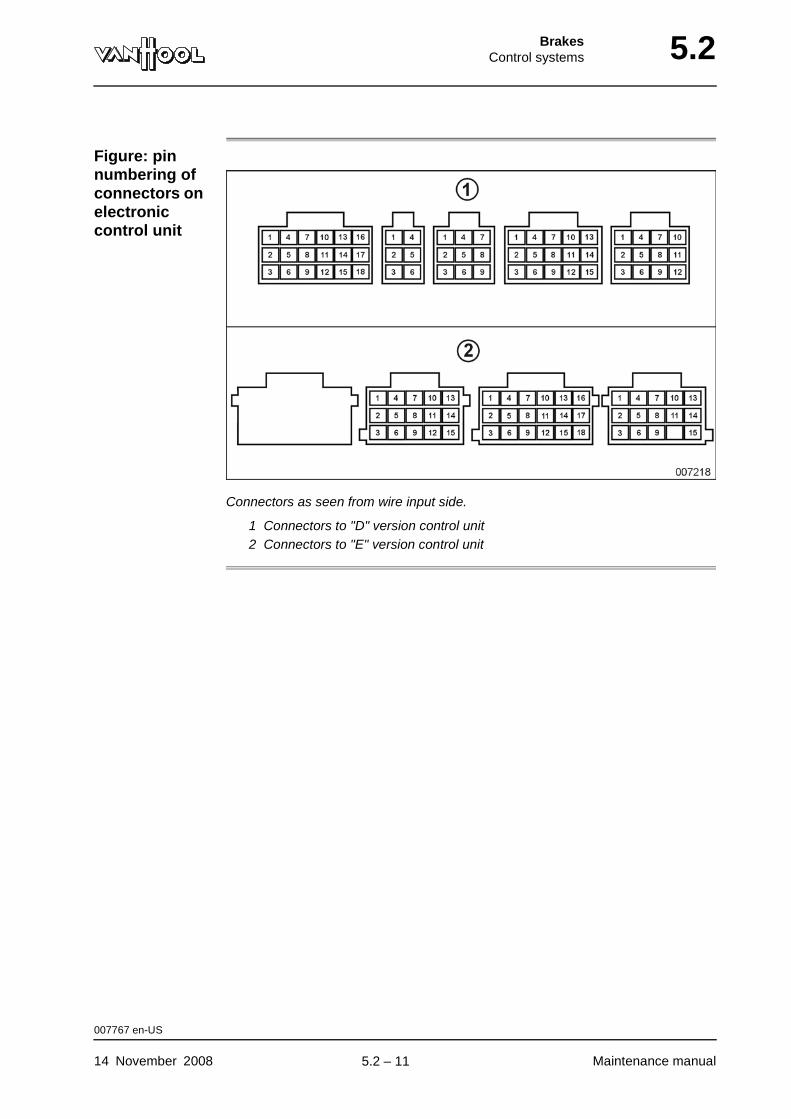
BrakesControl systems 5.2
Figure: pin numbering of connectors on electronic control unit
Connectors as seen from wire input side.
1 Connectors to "D" version control unit2 Connectors to "E" version control unit
007767 en-US
14 November 2008 Maintenance manual
.
5.2 – 11
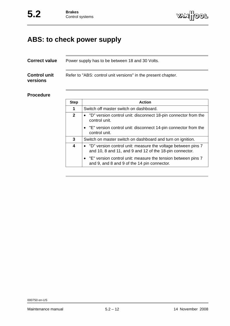
5.2 BrakesControl systems
ABS: to check power supply
Correct value Power supply has to be between 18 and 30 Volts.
Control unit versions
Refer to "ABS: control unit versions" in the present chapter.
Procedure
Step Action
1 Switch off master switch on dashboard.
2 • "D" version control unit: disconnect 18-pin connector from the control unit.
• "E" version control unit: disconnect 14-pin connector from the control unit.
3 Switch on master switch on dashboard and turn on ignition.
4 • "D" version control unit: measure the voltage between pins 7 and 10, 8 and 11, and 9 and 12 of the 18-pin connector.
• "E" version control unit: measure the tension between pins 7 and 9, and 8 and 9 of the 14 pin connector.
000750 en-US
Maintenance manual 14 November 2008
.
5.2 – 12

BrakesControl systems 5.2
To check ABS valve
Location of ABS valves
Refer to "ABS: structure" in the present chapter.
Figure: ABS valve terminals
Left: ABS valve with screw connection; right: ABS valve with bayonet coupling
1 Solenoid coil terminals2 Ground terminal
Correct resistance value
The resistance should be between 11.0 and 21.0 Ohms.
Equipment condition
Battery switch off
CAUTION!The pins of the connectors used in the ABS system are very fragile.
Procedure
Step Action
1 On the ABS control unit, pull the connector of the cable that leads to the ABS valve that has to be checked.
000749 en-US
14 November 2008 Maintenance manual
continued on next page.
5.2 – 13
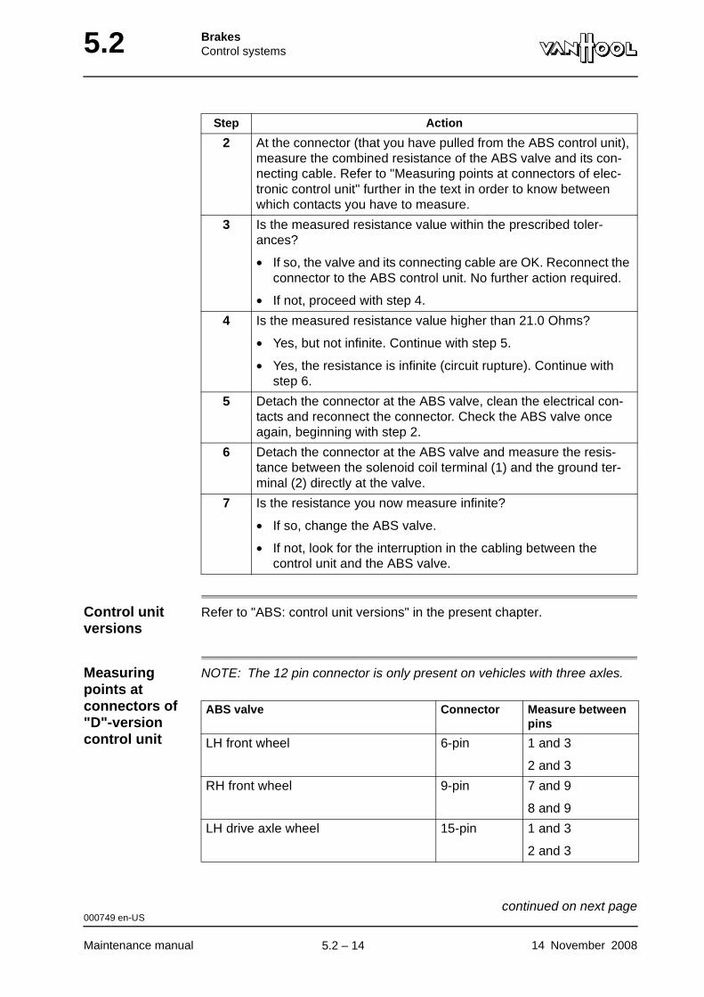
5.2 BrakesControl systems
Control unit versions
Refer to "ABS: control unit versions" in the present chapter.
Measuring points at connectors of "D"-version control unit
NOTE: The 12 pin connector is only present on vehicles with three axles.
2 At the connector (that you have pulled from the ABS control unit), measure the combined resistance of the ABS valve and its con-necting cable. Refer to "Measuring points at connectors of elec-tronic control unit" further in the text in order to know between which contacts you have to measure.
3 Is the measured resistance value within the prescribed toler-ances?
• If so, the valve and its connecting cable are OK. Reconnect the connector to the ABS control unit. No further action required.
• If not, proceed with step 4.
4 Is the measured resistance value higher than 21.0 Ohms?
• Yes, but not infinite. Continue with step 5.
• Yes, the resistance is infinite (circuit rupture). Continue with step 6.
5 Detach the connector at the ABS valve, clean the electrical con-tacts and reconnect the connector. Check the ABS valve once again, beginning with step 2.
6 Detach the connector at the ABS valve and measure the resis-tance between the solenoid coil terminal (1) and the ground ter-minal (2) directly at the valve.
7 Is the resistance you now measure infinite?
• If so, change the ABS valve.
• If not, look for the interruption in the cabling between the control unit and the ABS valve.
Step Action
ABS valve Connector Measure between pins
LH front wheel 6-pin 1 and 3
2 and 3
RH front wheel 9-pin 7 and 9
8 and 9
LH drive axle wheel 15-pin 1 and 3
2 and 3
000749 en-US
Maintenance manual 14 November 2008
continued on next page.
5.2 – 14

BrakesControl systems 5.2
Measuring points at connectors of "E"-version control unit
RH drive axle wheel 15-pin 10 and 12
11 and 12
LH trailer/trailing axle wheel 12-pin 1 and 3
2 and 3
RH trailer/trailing axle wheel 12-pin 10 and 12
11 and 12
ABS valve Connector Measure between pins
ABS valve Measure between
LH front wheel • contact 3 of 18 pin connector and contact 9 of 14 pin connector
• contact 6 of 18 pin connector and contact 9 of 14 pin connector
RH front wheel • contact 1 of 18 pin connector and contact 9 of 14 pin connector
• contact 4 of 18 pin connector and contact 9 of 14 pin connector
LH drive axle wheel • contact 2 of 18 pin connector and contact 9 of 14 pin connector
• contact 5 of 18 pin connector and contact 9 of 14 pin connector
RH drive axle wheel • contact 8 of 18 pin connector and contact 9 of 14 pin connector
• contact 9 of 18 pin connector and contact 9 of 14 pin connector
LH trailer/trailing axle wheel • contact 3 of 15 pin connector and contact 9 of 14 pin connector
• contact 6 of 15 pin connector and contact 9 of 14 pin connector
RH trailer/trailing axle wheel • contact 12 of 15 pin connector and contact 9 of 14 pin connector
• contact 15 of 15 pin connector and contact 9 of 14 pin connector
000749 en-US
14 November 2008 Maintenance manual
continued on next page.
5.2 – 15

5.2 BrakesControl systems
Figure: pin numbering of connectors on electronic control unit
Connectors as seen from wire input side.
1 Connectors to "D"-version control unit2 Connectors to "E"-version control unit
000749 en-US
Maintenance manual 14 November 2008
.
5.2 – 16

BrakesControl systems 5.2
To check ABS wheel-speed sensor
Location of ABS wheel-speed sensors
Refer to "ABS: structure" in the present chapter.
Figure: ABS wheel-speed sensor (example)
The wheel-speed sensor, the connecting cable and the plug form a whole.
1 Wheel-speed sensor2 Connecting cable3 Connector
Correct resistance value
The resistance should be between 900 and 2 000 Ohms.
Minimum output voltage
At least 0.2 Volt AC at 30 rpm.
Equipment condition
Battery switch off
CAUTION!The pins of the connectors used in the ABS system are very fragile.
000751 en-US
14 November 2008 Maintenance manual
continued on next page.
5.2 – 17
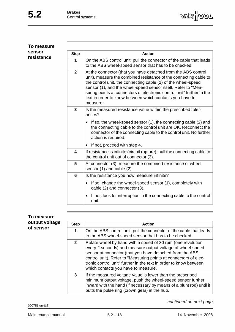
5.2 BrakesControl systems
To measure sensor resistance
To measure output voltage of sensor
Step Action
1 On the ABS control unit, pull the connector of the cable that leads to the ABS wheel-speed sensor that has to be checked.
2 At the connector (that you have detached from the ABS control unit), measure the combined resistance of the connecting cable to the control unit, the connecting cable (2) of the wheel-speed sensor (1), and the wheel-speed sensor itself. Refer to "Mea-suring points at connectors of electronic control unit" further in the text in order to know between which contacts you have to measure.
3 Is the measured resistance value within the prescribed toler-ances?
• If so, the wheel-speed sensor (1), the connecting cable (2) and the connecting cable to the control unit are OK. Reconnect the connector of the connecting cable to the control unit. No further action is required.
• If not, proceed with step 4.
4 If resistance is infinite (circuit rupture), pull the connecting cable to the control unit out of connector (3).
5 At connector (3), measure the combined resistance of wheel sensor (1) and cable (2).
6 Is the resistance you now measure infinite?
• If so, change the wheel-speed sensor (1), completely with cable (2) and connector (3).
• If not, look for interruption in the connecting cable to the control unit.
Step Action
1 On the ABS control unit, pull the connector of the cable that leads to the ABS wheel-speed sensor that has to be checked.
2 Rotate wheel by hand with a speed of 30 rpm (one revolution every 2 seconds) and measure output voltage of wheel-speed sensor at connector (that you have detached from the ABS control unit). Refer to "Measuring points at connectors of elec-tronic control unit" further in the text in order to know between which contacts you have to measure.
3 If the measured voltage value is lower than the prescribed minimum output voltage, push the wheel-speed sensor further inward with the hand (if necessary by means of a blunt rod) until it butts the pulse ring (crown gear) in the hub.
000751 en-US
Maintenance manual 14 November 2008
continued on next page.
5.2 – 18
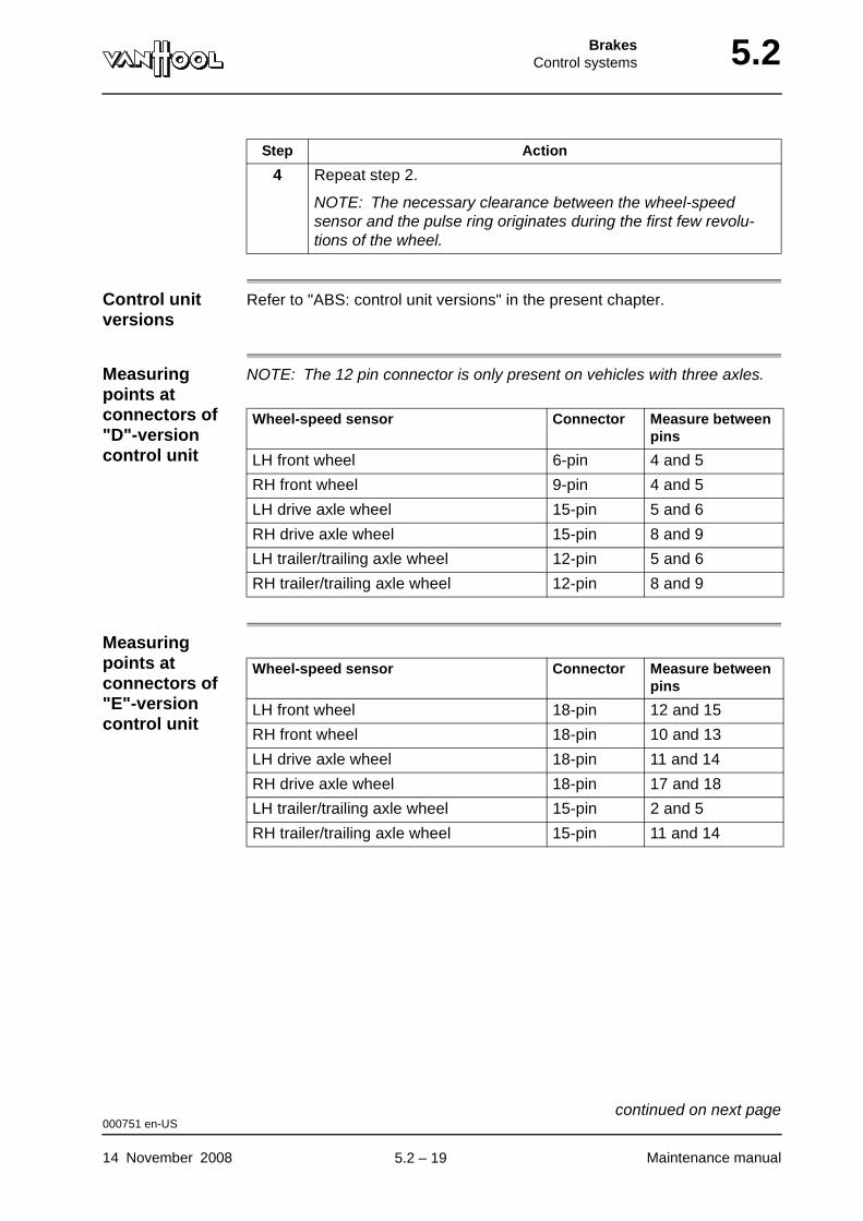
BrakesControl systems 5.2
Control unit versions
Refer to "ABS: control unit versions" in the present chapter.
Measuring points at connectors of "D"-version control unit
NOTE: The 12 pin connector is only present on vehicles with three axles.
Measuring points at connectors of "E"-version control unit
4 Repeat step 2.
NOTE: The necessary clearance between the wheel-speed sensor and the pulse ring originates during the first few revolu-tions of the wheel.
Step Action
Wheel-speed sensor Connector Measure between pins
LH front wheel 6-pin 4 and 5
RH front wheel 9-pin 4 and 5
LH drive axle wheel 15-pin 5 and 6
RH drive axle wheel 15-pin 8 and 9
LH trailer/trailing axle wheel 12-pin 5 and 6
RH trailer/trailing axle wheel 12-pin 8 and 9
Wheel-speed sensor Connector Measure between pins
LH front wheel 18-pin 12 and 15
RH front wheel 18-pin 10 and 13
LH drive axle wheel 18-pin 11 and 14
RH drive axle wheel 18-pin 17 and 18
LH trailer/trailing axle wheel 15-pin 2 and 5
RH trailer/trailing axle wheel 15-pin 11 and 14
000751 en-US
14 November 2008 Maintenance manual
continued on next page.
5.2 – 19
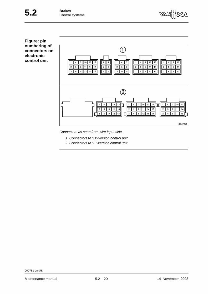
5.2 BrakesControl systems
Figure: pin numbering of connectors on electronic control unit
Connectors as seen from wire input side.
1 Connectors to "D"-version control unit2 Connectors to "E"-version control unit
000751 en-US
Maintenance manual 14 November 2008
.
5.2 – 20
BrakesControl systems 5.2
To install ABS wheel-speed sensor
Consumables
Procedure
Special high temperature grease Van Hool No. 10610096
"Blue seal" vaseline Van Hool No. 660852700
Step Action
1 Apply special high temperature grease to clamping bush and sensor.
2 Push clamping bush into place.
3 Push sensor into place by hand, until it contacts pulse ring.
The necessary gap between the sensor and the pulse ring will develop automatically, when the vehicle starts moving, at the first revolutions of the wheel.
4 NOTE: In order to prevent the ingress of water, fill wheel-speed sensor connector with "Blue seal" vaseline.
Connect wheel-speed sensor to chassis wiring.
000755 en-US
14 November 2008 Maintenance manual
.
5.2 – 21
5.2 BrakesControl systems
This page has been intentionally left blank.
000755 en-US
Maintenance manual 14 November 20085.2 – 22
BrakesCompressed-air brakes 5.10
Chapter 10: Compressed-air brakes
Overview
Introduction This chapter contains the compressed-air brakes.
Number of pages
20
Chapter publi-cation date
2 January 2008
Contents
Topic See page
Safety precautions concerning compressed air 5.10-2
Air line color codes 5.10-3
To test service-brake circuits for air-tightness 5.10-4
To check and lubricate the operating mechanism of the foot brake valve
5.10-7
To inspect brake chambers on front axle 5.10-9
To inspect brake chambers on drive axle 5.10-10
To inspect brake chambers on trailing axle 5.10-12
To check quick release valve of front wheel brakes 5.10-13
To check quick release double check valve of parking brake 5.10-14
To check relay valve of drive axle service brake 5.10-15
To check relay valve of trailing axle brakes 5.10-16
Safety precautions to be taken when exposed to brake dust 5.10-17
Knorr-Bremse SN7... disc brakes: maintenance 5.10-18
Knorr-Bremse SN7... disc brakes: to remove/install brake pads
5.10-19
Technical data: compressed-air brakes 5.10-20
2 January 2008 Maintenance manual
.
5.10 – 1
5.10 BrakesCompressed-air brakes
Safety precautions concerning compressed air
Cross-reference
Refer to chapter 13.1, "Complete compressed-air system".
003716 en-US
Maintenance manual 2 January 2008
.
5.10 – 2
BrakesCompressed-air brakes 5.10
Air line color codes
Cross-reference
Refer to chapter 13.25, "Air lines".
003718 en-US
2 January 2008 Maintenance manual
.
5.10 – 3
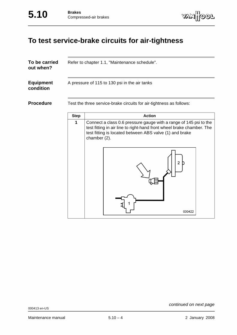
5.10 BrakesCompressed-air brakes
To test service-brake circuits for air-tightness
To be carried out when?
Refer to chapter 1.1, "Maintenance schedule".
Equipment condition
A pressure of 115 to 130 psi in the air tanks
Procedure Test the three service-brake circuits for air-tightness as follows:
Step Action
1 Connect a class 0.6 pressure gauge with a range of 145 psi to the test fitting in air line to right-hand front wheel brake chamber. The test fitting is located between ABS valve (1) and brake chamber (2).
000413 en-US
Maintenance manual 2 January 2008
continued on next page.
5.10 – 4
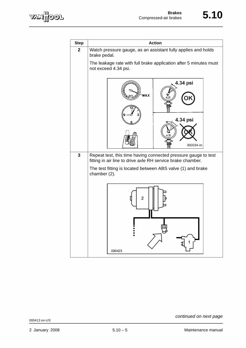
BrakesCompressed-air brakes 5.10
2 Watch pressure gauge, as an assistant fully applies and holds brake pedal.
The leakage rate with full brake application after 5 minutes must not exceed 4.34 psi.
3 Repeat test, this time having connected pressure gauge to test fitting in air line to drive axle RH service brake chamber.
The test fitting is located between ABS valve (1) and brake chamber (2).
Step Action
000413 en-US
2 January 2008 Maintenance manual
continued on next page.
5.10 – 5
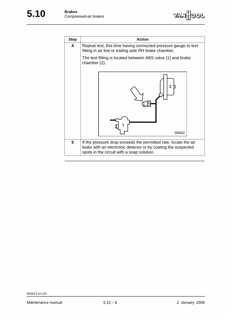
5.10 BrakesCompressed-air brakes
4 Repeat test, this time having connected pressure gauge to test fitting in air line to trailing axle RH brake chamber.
The test fitting is located between ABS valve (1) and brake chamber (2).
5 If the pressure drop exceeds the permitted rate, locate the air leaks with an electronic detector or by coating the suspected spots in the circuit with a soap solution.
Step Action
000413 en-US
Maintenance manual 2 January 2008
.
5.10 – 6
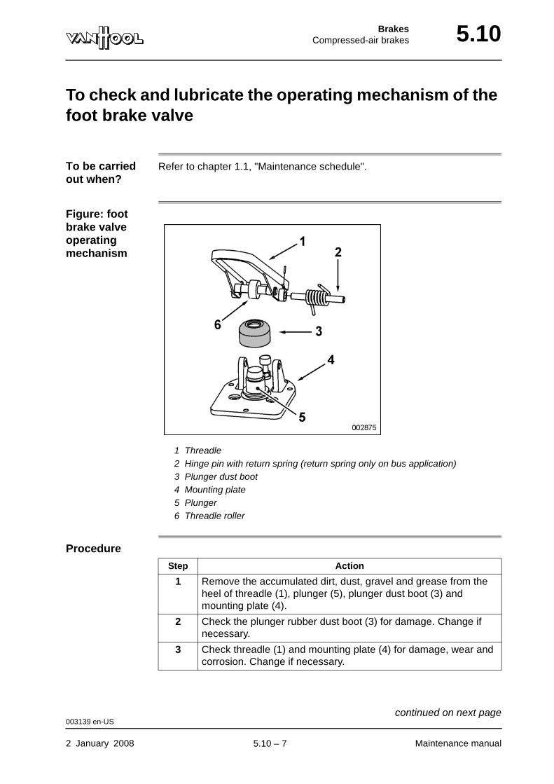
BrakesCompressed-air brakes 5.10
To check and lubricate the operating mechanism of the foot brake valve
To be carried out when?
Refer to chapter 1.1, "Maintenance schedule".
Figure: foot brake valve operating mechanism
1 Threadle2 Hinge pin with return spring (return spring only on bus application)3 Plunger dust boot4 Mounting plate5 Plunger6 Threadle roller
Procedure
Step Action
1 Remove the accumulated dirt, dust, gravel and grease from the heel of threadle (1), plunger (5), plunger dust boot (3) and mounting plate (4).
2 Check the plunger rubber dust boot (3) for damage. Change if necessary.
3 Check threadle (1) and mounting plate (4) for damage, wear and corrosion. Change if necessary.
003139 en-US
2 January 2008 Maintenance manual
continued on next page.
5.10 – 7

5.10 BrakesCompressed-air brakes
4 Apply 2 to 4 drops of oil between plunger (5) and mounting plate (4). Do not use too much oil!
5 Lubricate threadle roller (6), threadle roller pin and hinge pin (2) with thin oil.
Step Action
003139 en-US
Maintenance manual 2 January 2008
.
5.10 – 8
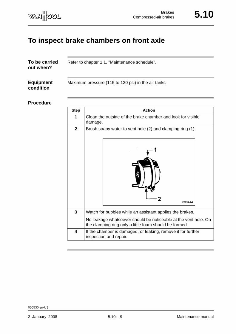
BrakesCompressed-air brakes 5.10
To inspect brake chambers on front axle
To be carried out when?
Refer to chapter 1.1, "Maintenance schedule".
Equipment condition
Maximum pressure (115 to 130 psi) in the air tanks
Procedure
Step Action
1 Clean the outside of the brake chamber and look for visible damage.
2 Brush soapy water to vent hole (2) and clamping ring (1).
3 Watch for bubbles while an assistant applies the brakes.
No leakage whatsoever should be noticeable at the vent hole. On the clamping ring only a little foam should be formed.
4 If the chamber is damaged, or leaking, remove it for further inspection and repair.
000530 en-US
2 January 2008 Maintenance manual
.
5.10 – 9
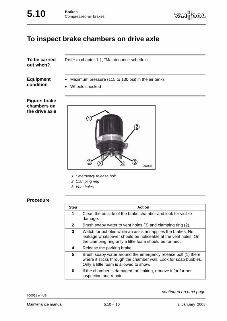
5.10 BrakesCompressed-air brakes
To inspect brake chambers on drive axle
To be carried out when?
Refer to chapter 1.1, "Maintenance schedule".
Equipment condition
• Maximum pressure (115 to 130 psi) in the air tanks
• Wheels chocked
Figure: brake chambers on the drive axle
1 Emergency release bolt2 Clamping ring3 Vent holes
Procedure
Step Action
1 Clean the outside of the brake chamber and look for visible damage.
2 Brush soapy water to vent holes (3) and clamping ring (2).
3 Watch for bubbles while an assistant applies the brakes. No leakage whatsoever should be noticeable at the vent holes. On the clamping ring only a little foam should be formed.
4 Release the parking brake.
5 Brush soapy water around the emergency release bolt (1) there where it sticks through the chamber wall. Look for soap bubbles. Only a little foam is allowed to show.
6 If the chamber is damaged, or leaking, remove it for further inspection and repair.
000531 en-US
Maintenance manual 2 January 2008
continued on next page.
5.10 – 10

BrakesCompressed-air brakes 5.10
000531 en-US
2 January 2008 Maintenance manual
.
5.10 – 11
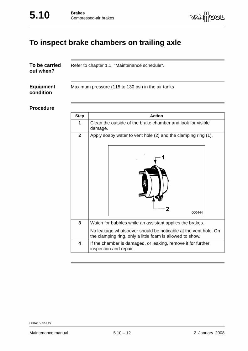
5.10 BrakesCompressed-air brakes
To inspect brake chambers on trailing axle
To be carried out when?
Refer to chapter 1.1, "Maintenance schedule".
Equipment condition
Maximum pressure (115 to 130 psi) in the air tanks
Procedure
Step Action
1 Clean the outside of the brake chamber and look for visible damage.
2 Apply soapy water to vent hole (2) and the clamping ring (1).
3 Watch for bubbles while an assistant applies the brakes.
No leakage whatsoever should be noticable at the vent hole. On the clamping ring, only a little foam is allowed to show.
4 If the chamber is damaged, or leaking, remove it for further inspection and repair.
000415 en-US
Maintenance manual 2 January 2008
.
5.10 – 12
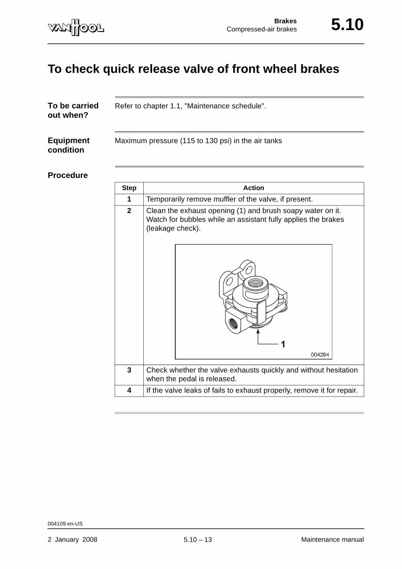
BrakesCompressed-air brakes 5.10
To check quick release valve of front wheel brakes
To be carried out when?
Refer to chapter 1.1, "Maintenance schedule".
Equipment condition
Maximum pressure (115 to 130 psi) in the air tanks
Procedure
Step Action
1 Temporarily remove muffler of the valve, if present.
2 Clean the exhaust opening (1) and brush soapy water on it. Watch for bubbles while an assistant fully applies the brakes (leakage check).
3 Check whether the valve exhausts quickly and without hesitation when the pedal is released.
4 If the valve leaks of fails to exhaust properly, remove it for repair.
004109 en-US
2 January 2008 Maintenance manual
.
5.10 – 13
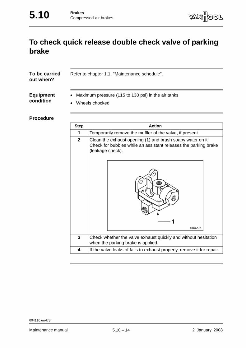
5.10 BrakesCompressed-air brakes
To check quick release double check valve of parking brake
To be carried out when?
Refer to chapter 1.1, "Maintenance schedule".
Equipment condition
• Maximum pressure (115 to 130 psi) in the air tanks
• Wheels chocked
Procedure
Step Action
1 Temporarily remove the muffler of the valve, if present.
2 Clean the exhaust opening (1) and brush soapy water on it. Check for bubbles while an assistant releases the parking brake (leakage check).
3 Check whether the valve exhaust quickly and without hesitation when the parking brake is applied.
4 If the valve leaks of fails to exhaust properly, remove it for repair.
004110 en-US
Maintenance manual 2 January 2008
.
5.10 – 14
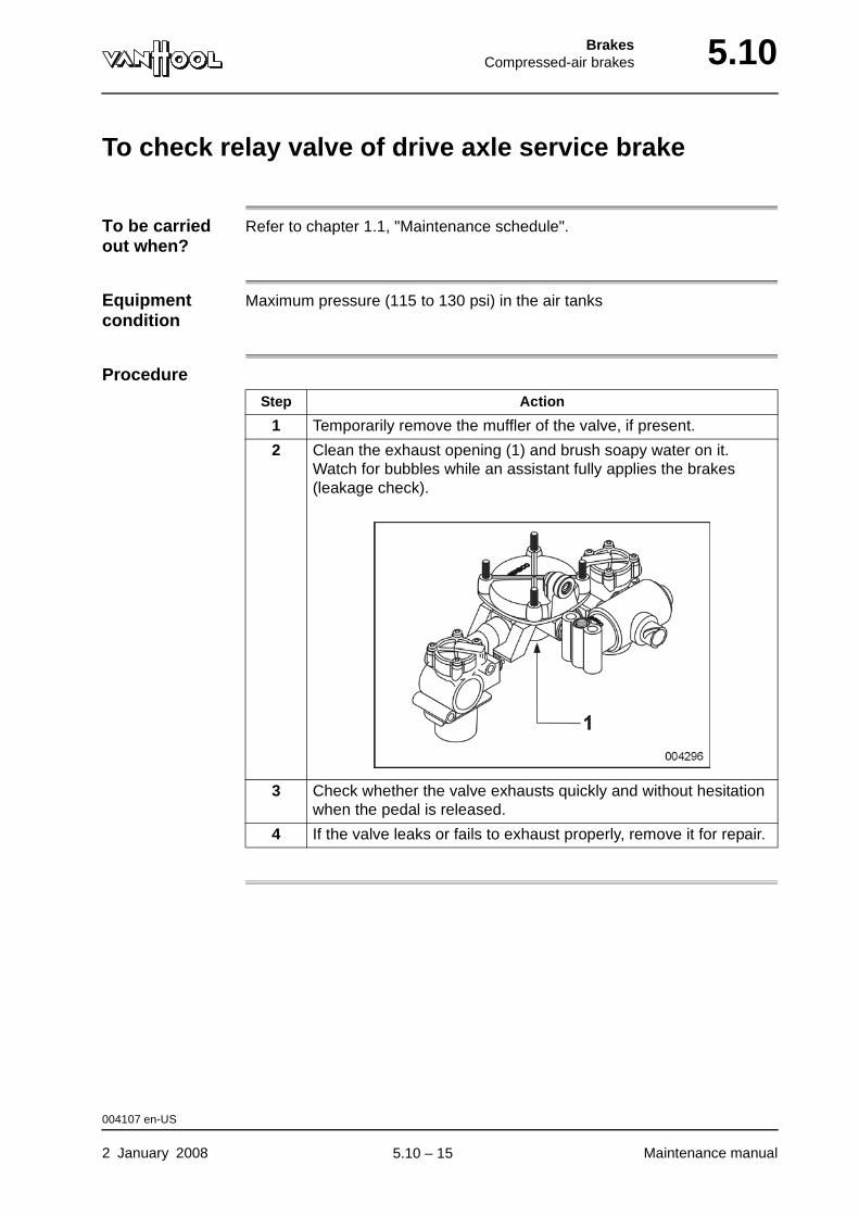
BrakesCompressed-air brakes 5.10
To check relay valve of drive axle service brake
To be carried out when?
Refer to chapter 1.1, "Maintenance schedule".
Equipment condition
Maximum pressure (115 to 130 psi) in the air tanks
Procedure
Step Action
1 Temporarily remove the muffler of the valve, if present.
2 Clean the exhaust opening (1) and brush soapy water on it. Watch for bubbles while an assistant fully applies the brakes (leakage check).
3 Check whether the valve exhausts quickly and without hesitation when the pedal is released.
4 If the valve leaks or fails to exhaust properly, remove it for repair.
004107 en-US
2 January 2008 Maintenance manual
.
5.10 – 15
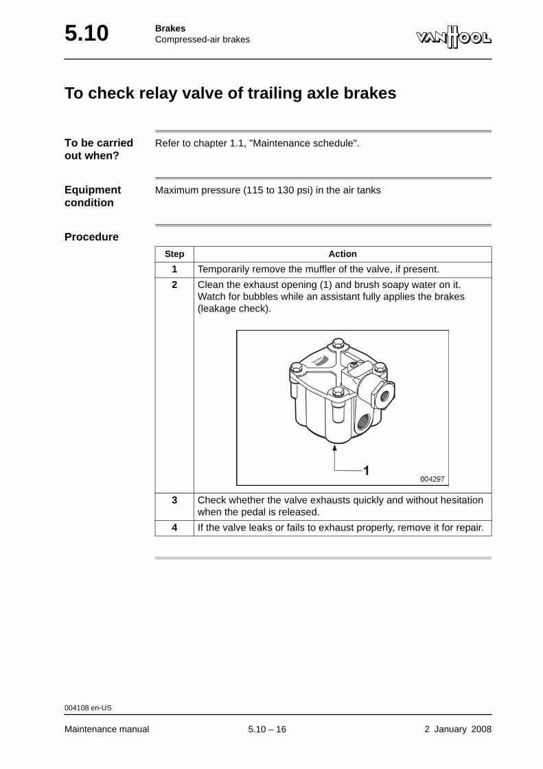
5.10 BrakesCompressed-air brakes
To check relay valve of trailing axle brakes
To be carried out when?
Refer to chapter 1.1, "Maintenance schedule".
Equipment condition
Maximum pressure (115 to 130 psi) in the air tanks
Procedure
Step Action
1 Temporarily remove the muffler of the valve, if present.
2 Clean the exhaust opening (1) and brush soapy water on it. Watch for bubbles while an assistant fully applies the brakes (leakage check).
3 Check whether the valve exhausts quickly and without hesitation when the pedal is released.
4 If the valve leaks or fails to exhaust properly, remove it for repair.
004108 en-US
Maintenance manual 2 January 2008
.
5.10 – 16

BrakesCompressed-air brakes 5.10
Safety precautions to be taken when exposed to brake dust
Introduction Consult the technical data in order to find out whether or not the brake pads are fitted with asbestos linings. Asbestos fibers cause cancer and asbestosis (a dangerous lung disease). The asbestos fibers are released into the air through brake lining wear. The instructions mentioned below are meant to prevent the creation of airborne brake dust and inhalation.
Experts do not agree on the harmless nature of asbestos-free brake linings. Therefore, it is recommended to observe the safety instructions, even when working with brakes containing non-asbestos material.
WARNING!To remove dust from brake parts or from the floor, use an industrial vacuum cleaner designed for this type of work. Do not use brushes or compressed air!
WARNING!Before removing a road wheel, vacuum the wheel disc first. After removing the wheel, vacuum around the brake caliper. Any remaining dust should be wiped using a wet rag. Used rags should be put in plastic waste bags, while still wet. Dust fallen on the floor should be removed immediately by means of a vacuum cleaner. Do not use brushes to sweep up dust. If necessary, wet the dust thoroughly and scrape it up.
WARNING!Asbestos-containing waste should be collected and transported in special sealed containers bearing warning labels.
000526 en-US
2 January 2008 Maintenance manual
.
5.10 – 17
5.10 BrakesCompressed-air brakes
Knorr-Bremse SN7... disc brakes: maintenance
To be carried out when?
Refer to chapter 1.1, "Maintenance schedule".
Procedure Follow the instructions mentioned in the manual “Service Manual Pneumatic Disc Brake SN7...” by Knorr-Bremse.
005724 en-US
Maintenance manual 2 January 2008
.
5.10 – 18
BrakesCompressed-air brakes 5.10
Knorr-Bremse SN7... disc brakes: to remove/install brake pads
Consumables
Setting values Refer to "Technical data" at the end of this chapter.
Tightening torques
Refer to "Technical data" at the end of this chapter.
CAUTION!Do not use brake pads with lining material different from that specified in the technical data.
CAUTION!Always change the brake pads on both axle ends at the same time.
CAUTION!When changing brake pads, always fit new brake pad hold-down springs and pad wear indicators.
Procedure Follow the instructions mentioned in the manual “Service Manual Pneumatic Disc Brake SN7...” by Knorr-Bremse.
Set of brake pads (four brake pads + four brake pad springs)
Van Hool No. .......... (Jurid 539-20)
Wear indicator set (two wear indicators + wire clip)
Van Hool No. ...........
005729 en-US
2 January 2008 Maintenance manual
.
5.10 – 19
5.10 BrakesCompressed-air brakes
Technical data: compressed-air brakes
Brake assembly
Brake disc
Brake pad
Tightening torques
Make Knorr-Bremse
Type SN7...
Brake clearance (brake pad-to-piston)
0.024 to 0.043 in
Maximum permissible run-out, when installed
0.002 in
Thickness, new 1.77 in
Maximum remachining thickness 1.57 in
Discard when worn to... 1.46 in
Lining thickness, new 0.83 in
Minimum permissible lining thickness
0.08 in
Lining material (Jurid 539-20) (asbestos-free)
Brake carrier fixing screws 300 ft.lbf
Front and trailing axles: screws securing brake disc and wheel flange to hub unit
300 ft.lbf
005730 en-US
Maintenance manual 2 January 2008
.
5.10 – 20
BrakesRetarder 5.14
Chapter 14: Retarder
Overview
Introduction This chapter deals with the speed retarder.
Number of pages
2
Chapter publi-cation date
2 January 2008
Contents
Topic See page
ZF retarder: maintenance 5.14-2
2 January 2008 Maintenance manual
.
5.14 – 1
5.14 BrakesRetarder
ZF retarder: maintenance
To check oil level
Refer to "ZF Astronic transmission with ZF retarder: to check oil level" in chapter 6.10.
To change oil Refer to "ZF Astronic transmission with ZF retarder: to change oil" in chapter 6.10.
To change oil filter
Refer to "ZF Astronic transmission with ZF retarder: to change oil filter" in chapter 6.10.
004205 en-US
Maintenance manual 2 January 2008
.
5.14 – 2

Part 6 - Transmission
Overview
Contents
Chapter See page
Chapter 10: Transmission 6.10-1

TransmissionTransmission 6.10
Chapter 10: Transmission
Overview
Introduction This chapter deals with the transmission.
Number of pages
30
Chapter publi-cation date
14 November 2008
Contents
Topic See page
Allison WTB500(R) transmission: to check oil level with cold transmission
6.10-2
Allison WTB500(R) transmission: to check oil level with warm transmission
6.10-4
Allison WTB500(R) transmission: to call up oil level with transmission selector
6.10-6
Allison WTB500(R) transmission: to retrieve condition of oil, oil filters and clutches by means of range selector
6.10-8
Allison WTB500(R) transmission: to change oil 6.10-10
Allison WTB500(R) transmission: to change oil filters 6.10-12
ZF Astronic transmission: troubleshooting 6.10-15
ZF Astronic transmission with ZF retarder: to check oil level 6.10-17
ZF Astronic transmission with ZF retarder: to change oil 6.10-19
ZF Astronic transmission with ZF retarder: to change oil filter
6.10-22
ZF Astronic transmission: to check breather 6.10-26
ZF Astronic transmission: to remove/install clutch cylinder 6.10-27
Technical data: transmission 6.10-29
14 November 2008 Maintenance manual
.
6.10 – 1
6.10 TransmissionTransmission
Allison WTB500(R) transmission: to check oil level with cold transmission
Introduction This check enables you to determine whether there is enough oil in the trans-mission so that it can safely operate until it's warmed up. Check the oil level again with a warm transmission.
Equipment condition
• Vehicle on level ground
• Parking brake applied
Location of dipstick and filler cap
Refer to chapter 1.1, "Access doors and controls at the outside".
Before starting the check
Procedure
Step Action
1 Check the oil level with the dipstick before you start the engine. The level should be close to the "HOT FULL" mark.
2 Top up with oil, if necessary.
Step Action
1 Start engine and let it idle for approximately 1 minute.
2 Engage briefly "D" and then "R" to bleed air from hydraulic cir-cuits.
3 Put the transmission in neutral and let the engine idle.
4 Pull out dipstick.
5 Wipe the dipstick clean with a cloth and reinsert it.
004441 en-US
Maintenance manual 14 November 2008
continued on next page.
6.10 – 2
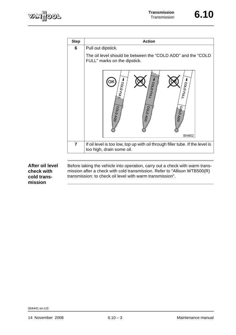
TransmissionTransmission 6.10
After oil level check with cold trans-mission
Before taking the vehicle into operation, carry out a check with warm trans-mission after a check with cold transmission. Refer to "Allison WTB500(R) transmission: to check oil level with warm transmission".
6 Pull out dipstick.
The oil level should be between the "COLD ADD" and the "COLD FULL" marks on the dipstick.
7 If oil level is too low, top up with oil through filler tube. If the level is too high, drain some oil.
Step Action
004441 en-US
14 November 2008 Maintenance manual
.
6.10 – 3
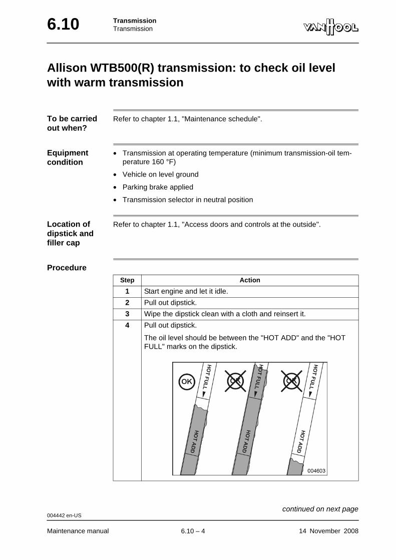
6.10 TransmissionTransmission
Allison WTB500(R) transmission: to check oil level with warm transmission
To be carried out when?
Refer to chapter 1.1, "Maintenance schedule".
Equipment condition
• Transmission at operating temperature (minimum transmission-oil tem-perature 160 °F)
• Vehicle on level ground
• Parking brake applied
• Transmission selector in neutral position
Location of dipstick and filler cap
Refer to chapter 1.1, "Access doors and controls at the outside".
Procedure
Step Action
1 Start engine and let it idle.
2 Pull out dipstick.
3 Wipe the dipstick clean with a cloth and reinsert it.
4 Pull out dipstick.
The oil level should be between the "HOT ADD" and the "HOT FULL" marks on the dipstick.
004442 en-US
Maintenance manual 14 November 2008
continued on next page.
6.10 – 4

TransmissionTransmission 6.10
5 If oil level is too low, top up with oil through filler tube. If oil level is too high, drain some oil.
Step Action
004442 en-US
14 November 2008 Maintenance manual
.
6.10 – 5
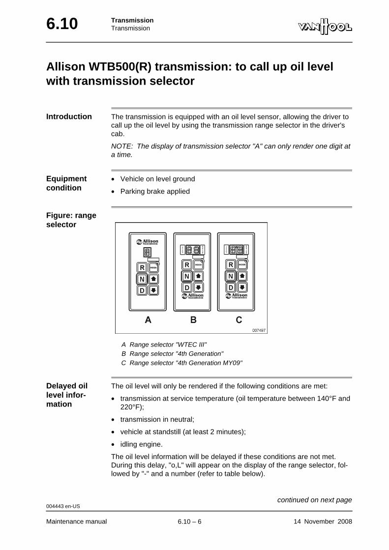
6.10 TransmissionTransmission
Allison WTB500(R) transmission: to call up oil level with transmission selector
Introduction The transmission is equipped with an oil level sensor, allowing the driver to call up the oil level by using the transmission range selector in the driver's cab.
NOTE: The display of transmission selector "A" can only render one digit at a time.
Equipment condition
• Vehicle on level ground
• Parking brake applied
Figure: range selector
A Range selector "WTEC III"B Range selector "4th Generation"C Range selector "4th Generation MY09"
Delayed oil level infor-mation
The oil level will only be rendered if the following conditions are met:
• transmission at service temperature (oil temperature between 140°F and 220°F);
• transmission in neutral;
• vehicle at standstill (at least 2 minutes);
• idling engine.
The oil level information will be delayed if these conditions are not met. During this delay, "o,L" will appear on the display of the range selector, fol-lowed by "-" and a number (refer to table below).
004443 en-US
Maintenance manual 14 November 2008
continued on next page.
6.10 – 6
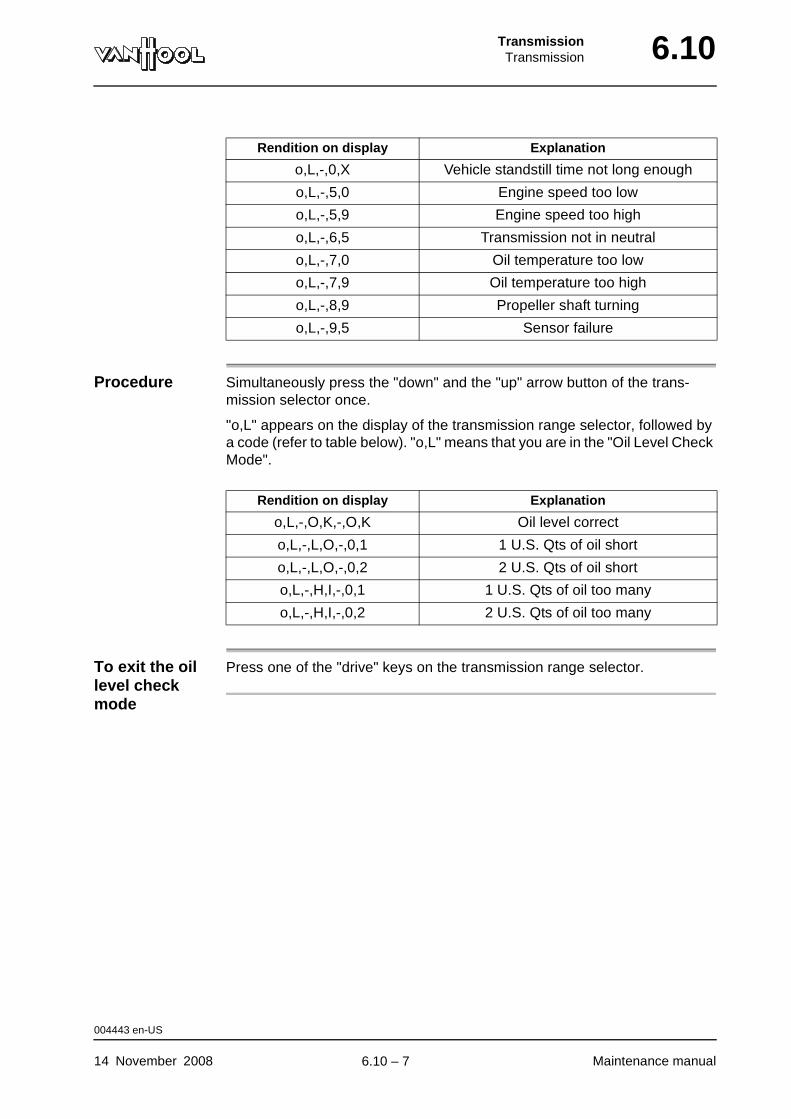
TransmissionTransmission 6.10
Procedure Simultaneously press the "down" and the "up" arrow button of the trans-mission selector once.
"o,L" appears on the display of the transmission range selector, followed by a code (refer to table below). "o,L" means that you are in the "Oil Level Check Mode".
To exit the oil level check mode
Press one of the "drive" keys on the transmission range selector.
Rendition on display Explanation
o,L,-,0,X Vehicle standstill time not long enough
o,L,-,5,0 Engine speed too low
o,L,-,5,9 Engine speed too high
o,L,-,6,5 Transmission not in neutral
o,L,-,7,0 Oil temperature too low
o,L,-,7,9 Oil temperature too high
o,L,-,8,9 Propeller shaft turning
o,L,-,9,5 Sensor failure
Rendition on display Explanation
o,L,-,O,K,-,O,K Oil level correct
o,L,-,L,O,-,0,1 1 U.S. Qts of oil short
o,L,-,L,O,-,0,2 2 U.S. Qts of oil short
o,L,-,H,I,-,0,1 1 U.S. Qts of oil too many
o,L,-,H,I,-,0,2 2 U.S. Qts of oil too many
004443 en-US
14 November 2008 Maintenance manual
.
6.10 – 7
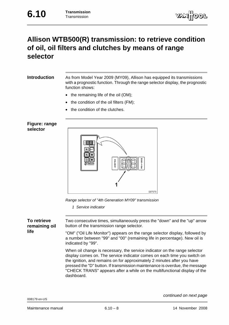
6.10 TransmissionTransmission
Allison WTB500(R) transmission: to retrieve condition of oil, oil filters and clutches by means of range selector
Introduction As from Model Year 2009 (MY09), Allison has equipped its transmissions with a prognostic function. Through the range selector display, the prognostic function shows:
• the remaining life of the oil (OM);
• the condition of the oil filters (FM);
• the condition of the clutches.
Figure: range selector
Range selector of "4th Generation MY09" transmission
1 Service indicator
To retrieve remaining oil life
Two consecutive times, simultaneously press the "down" and the "up" arrow button of the transmission range selector.
"OM" ("Oil Life Monitor") appears on the range selector display, followed by a number between "99" and "00" (remaining life in percentage). New oil is indicated by "99".
When oil change is necessary, the service indicator on the range selector display comes on. The service indicator comes on each time you switch on the ignition, and remains on for approximately 2 minutes after you have pressed the "D" button. If transmission maintenance is overdue, the message "CHECK TRANS" appears after a while on the multifunctional display of the dashboard.
008179 en-US
Maintenance manual 14 November 2008
continued on next page.
6.10 – 8
TransmissionTransmission 6.10
After an oil change, you have to reset the prognostic function. To this end, retrieve the "Oil Life Monitor" information and press the range selector "MODE" button for 10 seconds.
To retrieve oil filters condition
Three consecutive times, simultaneously press the "down" and the "up" arrow button of the transmission selector.
"FM" ("Filter Life Monitor") appears on the range selector display, followed by "OK" or "LO". "OK" means that the filter is still good, "LO" means that the filters have to be changed.
When the filters have to be changed, the service indicator on the range selector display starts to flash. The service indicator flashes each time you switch on the ignition, and will keep flashing for approximately 2 minutes after you have pressed the "D" button. If transmission maintenance is overdue, the message "CHECK TRANS" appears after a while on the multifunctional display of the dashboard.
After you have changed the filters, the prognostic function is reset automati-cally after a while.
To retrieve condition of clutches
Four consecutive times, simultaneously press the "down" and the "up" arrow button of the transmission selector.
"OK" or "LO" appears on the range selector display. "OK" means that the clutches are still good, "LO" means that the clutch has to be replaced. It is not indicated which clutch has to be replaced.
If one or more clutches have to be replaced, the service indicator on the range selector display comes on, and remains on while the vehicle is in service. If replacement of the clutches is overdue, the message "CHECK TRANS" appears after a while on the multifunctional display of the dash-board.
After you have replaced the clutches, the prognostic function is reset auto-matically after a while.
To exit prognostic function
Press one of the "drive" keys on the transmission range selector.
008179 en-US
14 November 2008 Maintenance manual
.
6.10 – 9

6.10 TransmissionTransmission
Allison WTB500(R) transmission: to change oil
To be carried out when?
Refer to chapter 1.1, "Maintenance schedule".
Oil type Refer to chapter 1.1, "Fluids and lubricants".
Consumables
Tightening torques
Refer to "Technical data" at the end of this chapter.
Equipment condition
• Transmission oil temperature at least 160 °F
• Engine stopped
Figure: bottom view of trans-mission
1 Oil pan drain plug
WARNING!Hot oil flowing out of the oil pan can cause scalds. Avoid contact with skin.
O-ring for oil pan drain plug
004444 en-US
Maintenance manual 14 November 2008
continued on next page.
6.10 – 10
TransmissionTransmission 6.10
Procedure
Step Action
1 Unscrew drain plug (1) from the oil pan and allow oil to drain.
2 Re-install the plug, with a new O-ring, in its place, and tighten it to the prescribed torque.
3 Fill the transmission with oil through filler tube.
4 Check the oil level (refer to "Allison WTB500(R) transmission: to check oil level with cold transmission").
5 Check the transmission for leaks.
6 Check the oil level with warm transmission (refer to "Allison WTB500(R) transmission: to check oil level with warm trans-mission").
004444 en-US
14 November 2008 Maintenance manual
.
6.10 – 11

6.10 TransmissionTransmission
Allison WTB500(R) transmission: to change oil filters
To be carried out when?
Refer to chapter 1.1, "Maintenance schedule".
Consumables
Tightening torques
Refer to "Technical data" at the end of this chapter.
Equipment condition
Oil drained, refer to "Allison WTB500(R) transmission: to change oil"
"MAIN + LUBE" filter set (two "High Capacity" filter elements + two O-rings + two sealing rings + two gaskets)
Allison No. 29545776
007270 en-US
Maintenance manual 14 November 2008
continued on next page.
6.10 – 12

TransmissionTransmission 6.10
Figure: bottom view of trans-mission
1 Fixing screw2 Filter cover3 Gasket4 Filter cover sealing-ring5 O-ring6 Filter
Procedure NOTE: Procedures for replacing "MAIN" and "LUBE" filters are identical.
Step Action
1 Remove the screws securing the filter cover to the transmission.
2 Remove the filter cover together with the filter element from the transmission.
3 Pull the filter element from the filter cover, and dispose of it in accordance with the environmental regulations.
4 Remove gasket (3) and sealing ring (4) from filter cover.
5 Lubricate O-ring (5) with oil, and place it on the filter element.
6 Place sealing ring (4) on the filter cover.
7 Install gasket (3).
8 Push the new filter element on the filter cover.
007270 en-US
14 November 2008 Maintenance manual
continued on next page.
6.10 – 13
6.10 TransmissionTransmission
9 Place the filter cover together with the new filter element into the filter housing and tighten the screws to the prescribed torque.
Step Action
007270 en-US
Maintenance manual 14 November 2008
.
6.10 – 14
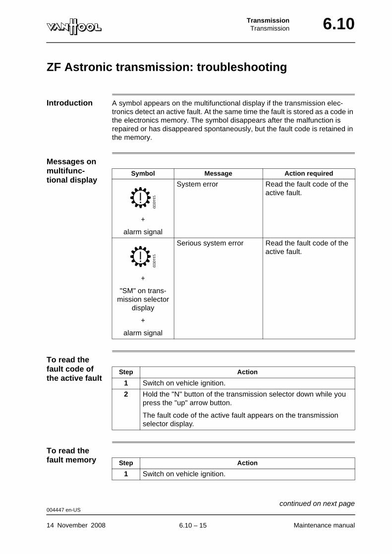
TransmissionTransmission 6.10
ZF Astronic transmission: troubleshooting
Introduction A symbol appears on the multifunctional display if the transmission elec-tronics detect an active fault. At the same time the fault is stored as a code in the electronics memory. The symbol disappears after the malfunction is repaired or has disappeared spontaneously, but the fault code is retained in the memory.
Messages on multifunc-tional display
To read the fault code of the active fault
To read the fault memory
Symbol Message Action required
+
alarm signal
System error Read the fault code of the active fault.
+
"SM" on trans-mission selector
display
+
alarm signal
Serious system error Read the fault code of the active fault.
Step Action
1 Switch on vehicle ignition.
2 Hold the "N" button of the transmission selector down while you press the "up" arrow button.
The fault code of the active fault appears on the transmission selector display.
Step Action
1 Switch on vehicle ignition.
004447 en-US
14 November 2008 Maintenance manual
continued on next page.
6.10 – 15
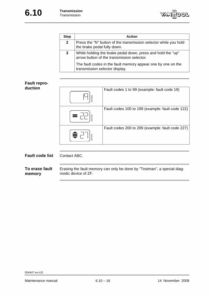
6.10 TransmissionTransmission
Fault repro-duction
Fault code list Contact ABC.
To erase fault memory
Erasing the fault memory can only be done by "Testman", a special diag-nostic device of ZF.
2 Press the "N" button of the transmission selector while you hold the brake pedal fully down.
3 While holding the brake pedal down, press and hold the "up" arrow button of the transmission selector.
The fault codes in the fault memory appear one by one on the transmission selector display.
Step Action
Fault codes 1 to 99 (example: fault code 19)
Fault codes 100 to 199 (example: fault code 122)
Fault codes 200 to 299 (example: fault code 227)
004447 en-US
Maintenance manual 14 November 2008
.
6.10 – 16
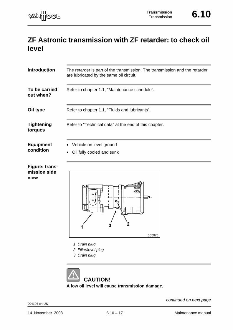
TransmissionTransmission 6.10
ZF Astronic transmission with ZF retarder: to check oil level
Introduction The retarder is part of the transmission. The transmission and the retarder are lubricated by the same oil circuit.
To be carried out when?
Refer to chapter 1.1, "Maintenance schedule".
Oil type Refer to chapter 1.1, "Fluids and lubricants".
Tightening torques
Refer to "Technical data" at the end of this chapter.
Equipment condition
• Vehicle on level ground
• Oil fully cooled and sunk
Figure: trans-mission side view
1 Drain plug2 Filler/level plug3 Drain plug
CAUTION!A low oil level will cause transmission damage.
004196 en-US
14 November 2008 Maintenance manual
continued on next page.
6.10 – 17
6.10 TransmissionTransmission
CAUTION!Do not activate the retarder before shutting off the engine, if the oil level has to be checked. Otherwise part of the oil will flow to the retarder, and the oil level check, taking place in the transmission housing, will be inaccurate.
Procedure
Step Action
1 Clean the surroundings of filler/level plug (2) and unscrew the plug.
The oil must reach the edge of the filler/level plug opening.
2 If necessary, top up with oil through the same opening.
3 Install plug (2) and tighten it with the prescribed torque.
004196 en-US
Maintenance manual 14 November 2008
.
6.10 – 18
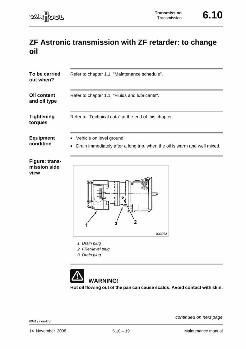
TransmissionTransmission 6.10
ZF Astronic transmission with ZF retarder: to change oil
To be carried out when?
Refer to chapter 1.1, "Maintenance schedule".
Oil content and oil type
Refer to chapter 1.1, "Fluids and lubricants".
Tightening torques
Refer to "Technical data" at the end of this chapter.
Equipment condition
• Vehicle on level ground.
• Drain immediately after a long trip, when the oil is warm and well mixed.
Figure: trans-mission side view
1 Drain plug2 Filler/level plug3 Drain plug
WARNING!Hot oil flowing out of the pan can cause scalds. Avoid contact with skin.
004197 en-US
14 November 2008 Maintenance manual
continued on next page.
6.10 – 19
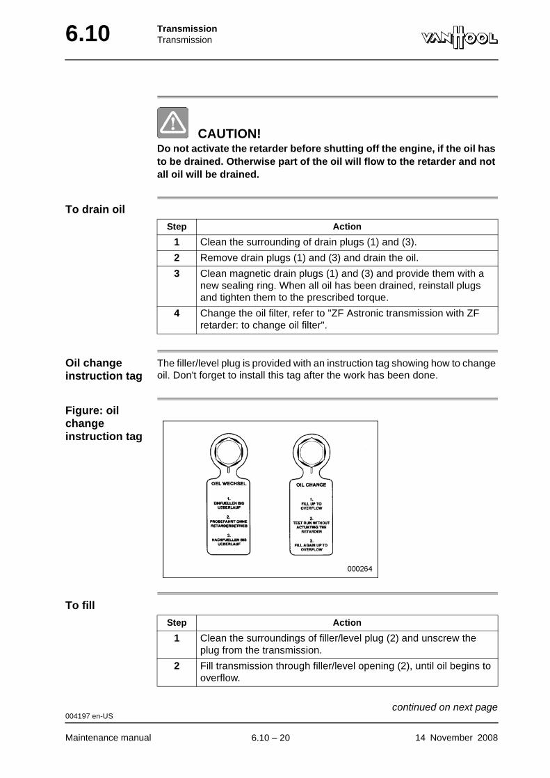
6.10 TransmissionTransmission
CAUTION!Do not activate the retarder before shutting off the engine, if the oil has to be drained. Otherwise part of the oil will flow to the retarder and not all oil will be drained.
To drain oil
Oil change instruction tag
The filler/level plug is provided with an instruction tag showing how to change oil. Don't forget to install this tag after the work has been done.
Figure: oil change instruction tag
To fill
Step Action
1 Clean the surrounding of drain plugs (1) and (3).
2 Remove drain plugs (1) and (3) and drain the oil.
3 Clean magnetic drain plugs (1) and (3) and provide them with a new sealing ring. When all oil has been drained, reinstall plugs and tighten them to the prescribed torque.
4 Change the oil filter, refer to "ZF Astronic transmission with ZF retarder: to change oil filter".
Step Action
1 Clean the surroundings of filler/level plug (2) and unscrew the plug from the transmission.
2 Fill transmission through filler/level opening (2), until oil begins to overflow.
004197 en-US
Maintenance manual 14 November 2008
continued on next page.
6.10 – 20
TransmissionTransmission 6.10
3 Reinstall filler/level plug (2) with a new sealing ring and tighten it to the prescribed torque.
4 NOTE: Do not activate the retarder during test drive!
Go for a test drive of 2 to 3 miles.
5 Position the vehicle above an inspection pit and shut the engine off. Do not activate the retarder.
6 Unscrew filler/level plug (2) from transmission and check the oil level.
7 If necessary, top up until the oil overflows.
8 Install filler/level plug (2) and tighten it with the prescribed torque.
9 Attach oil change instruction tag to filler/level plug (2).
Step Action
004197 en-US
14 November 2008 Maintenance manual
.
6.10 – 21
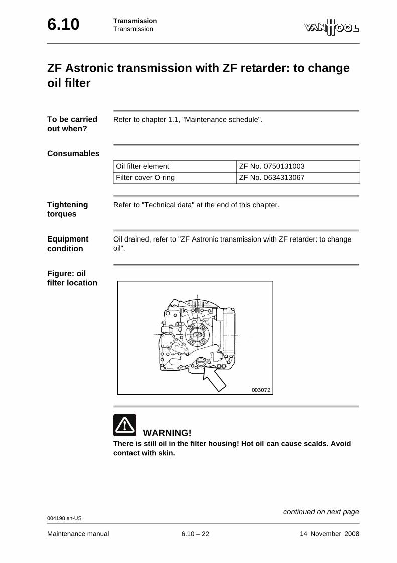
6.10 TransmissionTransmission
ZF Astronic transmission with ZF retarder: to change oil filter
To be carried out when?
Refer to chapter 1.1, "Maintenance schedule".
Consumables
Tightening torques
Refer to "Technical data" at the end of this chapter.
Equipment condition
Oil drained, refer to "ZF Astronic transmission with ZF retarder: to change oil".
Figure: oil filter location
WARNING!There is still oil in the filter housing! Hot oil can cause scalds. Avoid contact with skin.
Oil filter element ZF No. 0750131003
Filter cover O-ring ZF No. 0634313067
004198 en-US
Maintenance manual 14 November 2008
continued on next page.
6.10 – 22
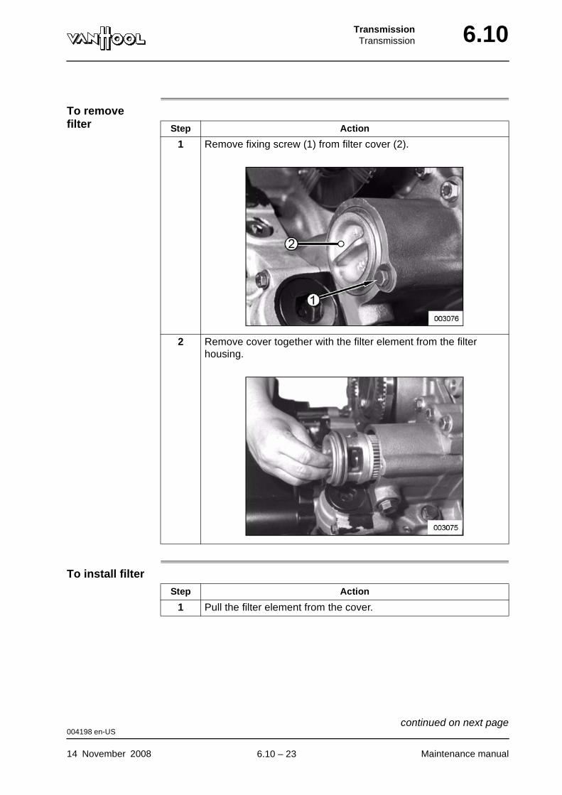
TransmissionTransmission 6.10
To remove filter
To install filter
Step Action
1 Remove fixing screw (1) from filter cover (2).
2 Remove cover together with the filter element from the filter housing.
Step Action
1 Pull the filter element from the cover.
004198 en-US
14 November 2008 Maintenance manual
continued on next page.
6.10 – 23
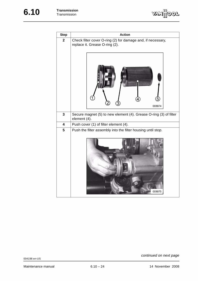
6.10 TransmissionTransmission
2 Check filter cover O-ring (2) for damage and, if necessary, replace it. Grease O-ring (2).
3 Secure magnet (5) to new element (4). Grease O-ring (3) of filter element (4).
4 Push cover (1) of filter element (4).
5 Push the filter assembly into the filter housing until stop.
Step Action
004198 en-US
Maintenance manual 14 November 2008
continued on next page.
6.10 – 24
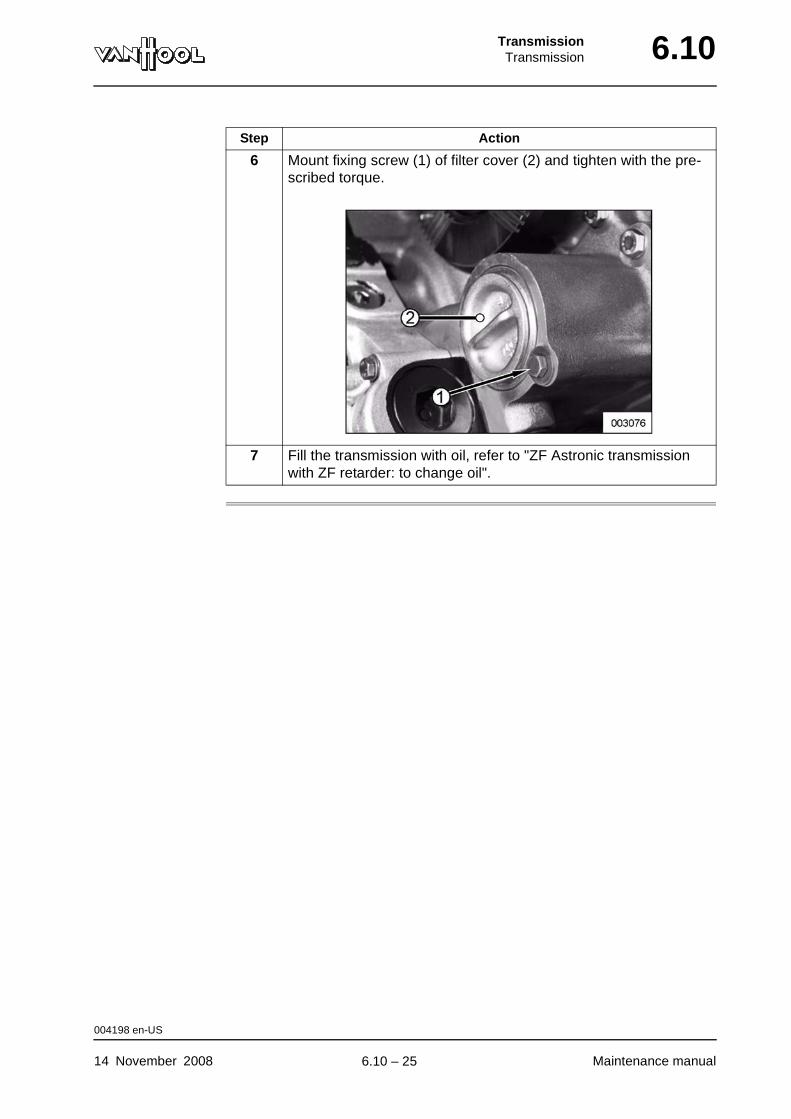
TransmissionTransmission 6.10
6 Mount fixing screw (1) of filter cover (2) and tighten with the pre-scribed torque.
7 Fill the transmission with oil, refer to "ZF Astronic transmission with ZF retarder: to change oil".
Step Action
004198 en-US
14 November 2008 Maintenance manual
.
6.10 – 25

6.10 TransmissionTransmission
ZF Astronic transmission: to check breather
To be carried out when?
Refer to chapter 1.1, "Maintenance schedule".
Figure: trans-mission breather
Why check breather?
If the breather is clogged, pressure builds up in the transmission due to tem-perature rise while driving. As a result of which leakage of the oil seal could occur. To prevent this you should check and, if necessary, clean the breather regularly.
004204 en-US
Maintenance manual 14 November 2008
.
6.10 – 26
TransmissionTransmission 6.10
ZF Astronic transmission: to remove/install clutch cylinder
WARNING!Never disconnect a line containing pressure. Never remove a com-ponent unless you are certain all system pressure has been depleted.
WARNING!Always wear safety goggles.
Clutch cylinder
The clutch cylinder is secured to the clutch bell housing and is accessible from underneath the vehicle. The air-operated clutch cylinder is activated by the transmission electronics.
To remove
WARNING!The transmission electronics activate the clutch cylinder also each time the ignition is switched on (the push rod of the clutch cylinder moves outwards with a force of 4 500 lbf). Follow the procedure below to prevent this from happening when the clutch cylinder has been removed from the clutch bell housing (body injury danger!).
Step Action
1 Switch off the vehicle ignition.
2 Switch off master switch on dashboard.
3 Release pressure from the air system through drain valves on the compressed-air tanks. For location of compressed-air tanks, refer to chapter 13.17.
4 Remove the clutch cylinder.
004203 en-US
14 November 2008 Maintenance manual
continued on next page.
6.10 – 27

6.10 TransmissionTransmission
To install
WARNING!Ensure that the compressed-air system is without pressure before installing the clutch cylinder.
004203 en-US
Maintenance manual 14 November 2008
.
6.10 – 28
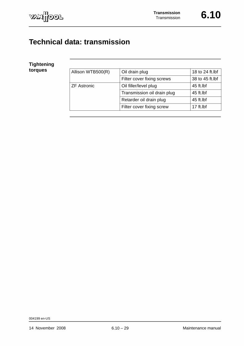
TransmissionTransmission 6.10
Technical data: transmission
Tightening torques Allison WTB500(R) Oil drain plug 18 to 24 ft.lbf
Filter cover fixing screws 38 to 45 ft.lbf
ZF Astronic Oil filler/level plug 45 ft.lbf
Transmission oil drain plug 45 ft.lbf
Retarder oil drain plug 45 ft.lbf
Filter cover fixing screw 17 ft.lbf
004199 en-US
14 November 2008 Maintenance manual
.
6.10 – 29

6.10 TransmissionTransmission
This page has been intentionally left blank.
004199 en-US
Maintenance manual 14 November 20086.10 – 30

Part 7 - Steering
Overview
Contents
Chapter See page
Chapter 6: Front axle steering system 7.6-1

SteeringFront axle steering system 7.6
Chapter 6: Front axle steering system
Overview
Introduction This chapter deals with the front axle steering system.
Number of pages
54
Chapter publi-cation date
14 November 2008
Contents
Topic See page
To check power steering fluid level 7.6-3
To change fluid of power steering system 7.6-5
To connect the "Servotest 570" tester 7.6-8
To check maximum steering pump pressure 7.6-11
To check steering pump flow 7.6-13
To check/set hydraulic steering limitation 7.6-14
To check steering gear pressure 7.6-19
To check steering gear for internal leakage 7.6-21
To check return time of power steering valve 7.6-24
To check steering wheel play 7.6-25
To change filter in steering fluid tank 7.6-28
To check steering fluid lines for leaks 7.6-30
To check security of steering gear, rods and levers 7.6-31
To check steering gear mesh load 7.6-32
To dismantle steering gear 7.6-34
To lubricate intermediate lever of steering system 7.6-35
To check linkage joints 7.6-36
To check clamps of drag-link and tie-rod 7.6-40
To check drag-link and tie-rod tubes 7.6-41
To check straight-ahead position of wheels 7.6-42
To check maximum steering lock angles 7.6-43
To check steering column bearings for play 7.6-44
To check universal joints and flex couplings 7.6-45
14 November 2008 Maintenance manual
continued on next page.
7.6 – 1
7.6 SteeringFront axle steering system
To remove steering assembly 7.6-46
To inspect the steering gear splash-water protective cover 7.6-47
Technical data: front axle steering system 7.6-49
Special tools: front axle steering system 7.6-52
Topic See page
Maintenance manual 14 November 2008
.
7.6 – 2
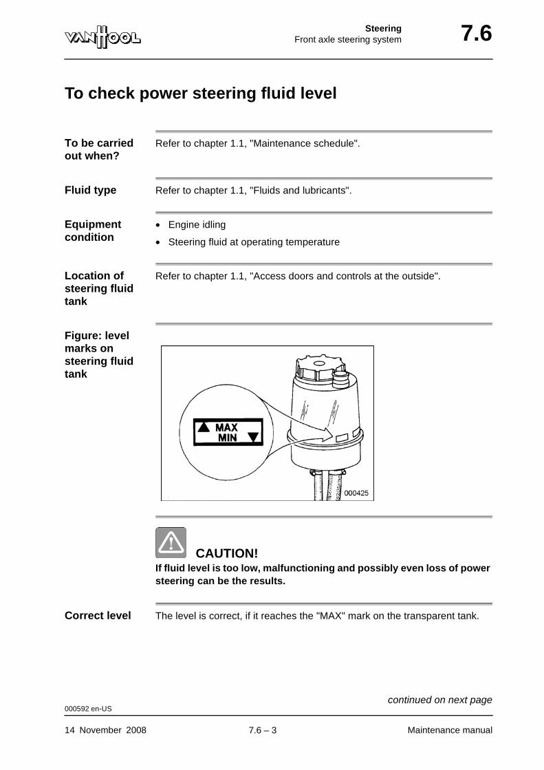
SteeringFront axle steering system 7.6
To check power steering fluid level
To be carried out when?
Refer to chapter 1.1, "Maintenance schedule".
Fluid type Refer to chapter 1.1, "Fluids and lubricants".
Equipment condition
• Engine idling
• Steering fluid at operating temperature
Location of steering fluid tank
Refer to chapter 1.1, "Access doors and controls at the outside".
Figure: level marks on steering fluid tank
CAUTION!If fluid level is too low, malfunctioning and possibly even loss of power steering can be the results.
Correct level The level is correct, if it reaches the "MAX" mark on the transparent tank.
000592 en-US
14 November 2008 Maintenance manual
continued on next page.
7.6 – 3
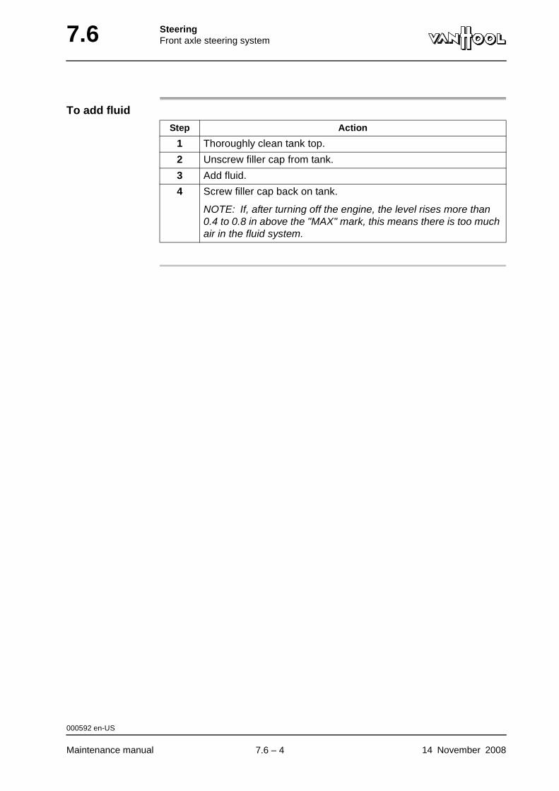
7.6 SteeringFront axle steering system
To add fluid
Step Action
1 Thoroughly clean tank top.
2 Unscrew filler cap from tank.
3 Add fluid.
4 Screw filler cap back on tank.
NOTE: If, after turning off the engine, the level rises more than 0.4 to 0.8 in above the "MAX" mark, this means there is too much air in the fluid system.
000592 en-US
Maintenance manual 14 November 2008
.
7.6 – 4
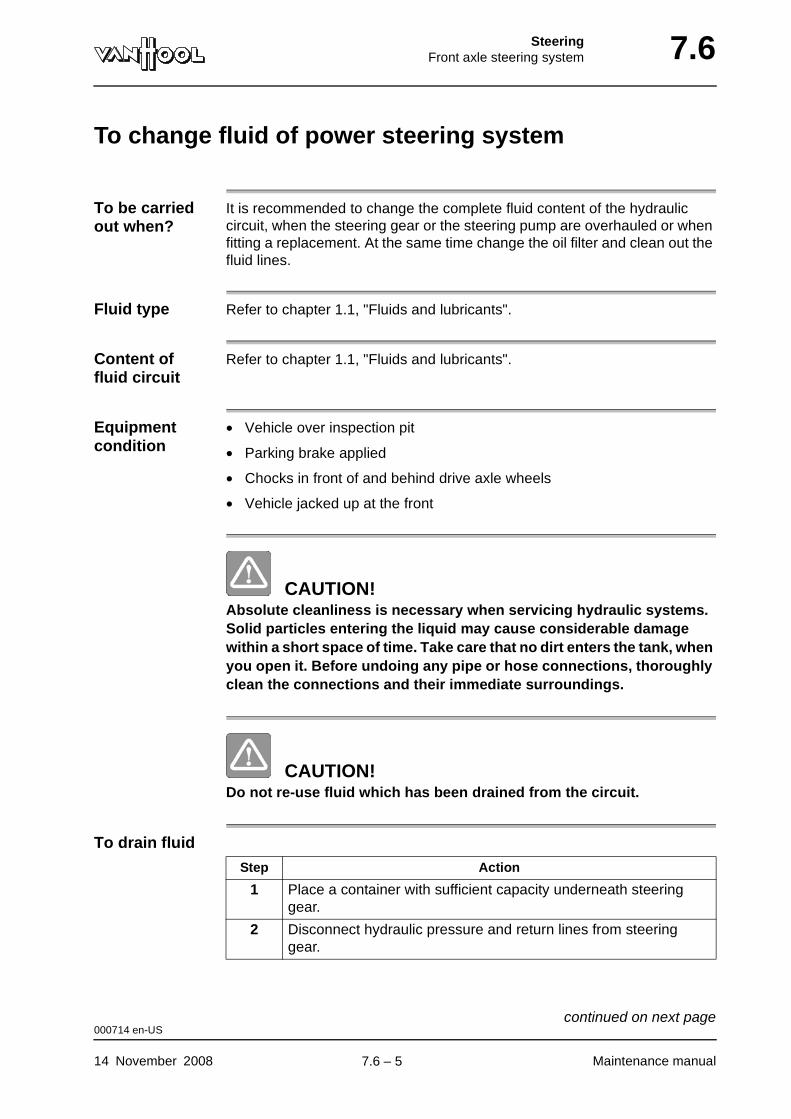
SteeringFront axle steering system 7.6
To change fluid of power steering system
To be carried out when?
It is recommended to change the complete fluid content of the hydraulic circuit, when the steering gear or the steering pump are overhauled or when fitting a replacement. At the same time change the oil filter and clean out the fluid lines.
Fluid type Refer to chapter 1.1, "Fluids and lubricants".
Content of fluid circuit
Refer to chapter 1.1, "Fluids and lubricants".
Equipment condition
• Vehicle over inspection pit
• Parking brake applied
• Chocks in front of and behind drive axle wheels
• Vehicle jacked up at the front
CAUTION!Absolute cleanliness is necessary when servicing hydraulic systems. Solid particles entering the liquid may cause considerable damage within a short space of time. Take care that no dirt enters the tank, when you open it. Before undoing any pipe or hose connections, thoroughly clean the connections and their immediate surroundings.
CAUTION!Do not re-use fluid which has been drained from the circuit.
To drain fluid
Step Action
1 Place a container with sufficient capacity underneath steering gear.
2 Disconnect hydraulic pressure and return lines from steering gear.
000714 en-US
14 November 2008 Maintenance manual
continued on next page.
7.6 – 5
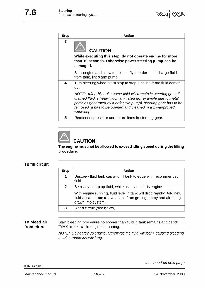
7.6 SteeringFront axle steering system
CAUTION!The engine must not be allowed to exceed idling speed during the filling procedure.
To fill circuit
To bleed air from circuit
Start bleeding procedure no sooner than fluid in tank remains at dipstick "MAX" mark, while engine is running.
NOTE: Do not rev up engine. Otherwise the fluid will foam, causing bleeding to take unnecessarily long.
3
CAUTION!While executing this step, do not operate engine for more than 10 seconds. Otherwise power steering pump can be damaged.
Start engine and allow to idle briefly in order to discharge fluid from tank, lines and pump.
4 Turn steering wheel from stop to stop, until no more fluid comes out.
NOTE: After this quite some fluid will remain in steering gear. If drained fluid is heavily contaminated (for example due to metal particles generated by a defective pump), steering gear has to be removed. It has to be opened and cleaned in a ZF-approved workshop.
5 Reconnect pressure and return lines to steering gear.
Step Action
Step Action
1 Unscrew fluid tank cap and fill tank to edge with recommended fluid.
2 Be ready to top up fluid, while assistant starts engine.
With engine running, fluid level in tank will drop rapidly. Add new fluid at same rate to avoid tank from getting empty and air being drawn into system.
3 Bleed circuit (see below).
000714 en-US
Maintenance manual 14 November 2008
continued on next page.
7.6 – 6
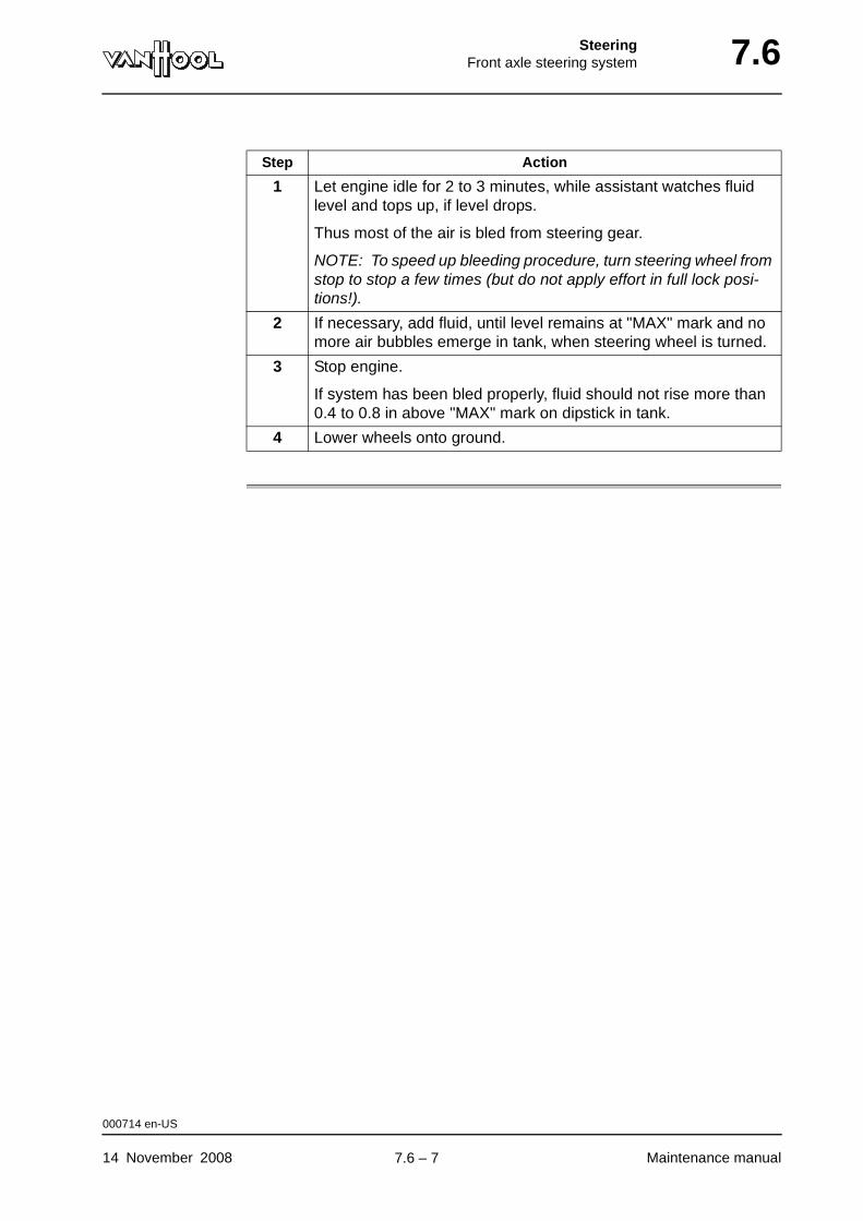
SteeringFront axle steering system 7.6
Step Action
1 Let engine idle for 2 to 3 minutes, while assistant watches fluid level and tops up, if level drops.
Thus most of the air is bled from steering gear.
NOTE: To speed up bleeding procedure, turn steering wheel from stop to stop a few times (but do not apply effort in full lock posi-tions!).
2 If necessary, add fluid, until level remains at "MAX" mark and no more air bubbles emerge in tank, when steering wheel is turned.
3 Stop engine.
If system has been bled properly, fluid should not rise more than 0.4 to 0.8 in above "MAX" mark on dipstick in tank.
4 Lower wheels onto ground.
000714 en-US
14 November 2008 Maintenance manual
.
7.6 – 7
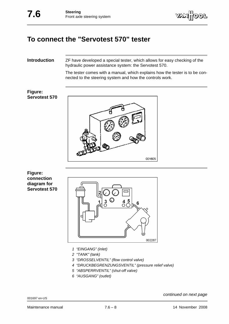
7.6 SteeringFront axle steering system
To connect the "Servotest 570" tester
Introduction ZF have developed a special tester, which allows for easy checking of the hydraulic power assistance system: the Servotest 570.
The tester comes with a manual, which explains how the tester is to be con-nected to the steering system and how the controls work.
Figure: Servotest 570
Figure: connection diagram for Servotest 570
1 “EINGANG” (inlet)2 “TANK” (tank)3 “DROSSELVENTIL” (flow control valve)4 “DRUCKBEGRENZUNGSVENTIL” (pressure relief valve)5 “ABSPERRVENTIL” (shut-off valve)6 “AUSGANG” (outlet)
001697 en-US
Maintenance manual 14 November 2008
continued on next page.
7.6 – 8
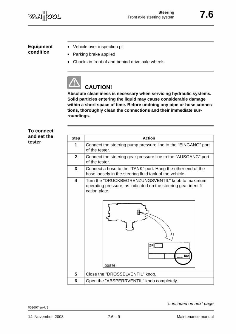
SteeringFront axle steering system 7.6
Equipment condition
• Vehicle over inspection pit
• Parking brake applied
• Chocks in front of and behind drive axle wheels
CAUTION!Absolute cleanliness is necessary when servicing hydraulic systems. Solid particles entering the liquid may cause considerable damage within a short space of time. Before undoing any pipe or hose connec-tions, thoroughly clean the connections and their immediate sur-roundings.
To connect and set the tester
Step Action
1 Connect the steering pump pressure line to the "EINGANG" port of the tester.
2 Connect the steering gear pressure line to the "AUSGANG" port of the tester.
3 Connect a hose to the "TANK" port. Hang the other end of the hose loosely in the steering fluid tank of the vehicle.
4 Turn the "DRUCKBEGRENZUNGSVENTIL" knob to maximum operating pressure, as indicated on the steering gear identifi-cation plate.
5 Close the "DROSSELVENTIL" knob.
6 Open the "ABSPERRVENTIL" knob completely.
001697 en-US
14 November 2008 Maintenance manual
continued on next page.
7.6 – 9

7.6 SteeringFront axle steering system
Before carrying out the checks with the tester
After you have connected and set the tester, proceed as follows before checking the steering system:
To bring the steering fluid up to testing temperature
You can use the tester to bring the steering fluid up to testing temperature.
Before putting the vehicle into service
Step Action
1 Bleed the installation, refer to "To change fluid of power steering system" in the present chapter
2 Heat the steering fluid to 50 °C (122 °F), refer to "To bring the steering fluid up to testing temperature" below.
3 Check the fluid level, refer to "To check power steering fluid level" in the present chapter.
Step Action
1 Let the engine idle.
2 Set the pressure to 50 bar (725 psi) with the "ABSPERRVENTIL" shut-off valve.
3 Wait until the built-in thermometer indicates the desired temper-ature, then turn the shut-off valve completely open.
Step Action
1 Disconnect the tester.
2 Connect the pressure lines.
3 Bleed the installation, refer to "To change fluid of power steering system" in the present chapter
4 Check the fluid level, refer to "To check power steering fluid level" in the present chapter.
001697 en-US
Maintenance manual 14 November 2008
.
7.6 – 10
SteeringFront axle steering system 7.6
To check maximum steering pump pressure
To be carried out when?
At each major inspection of the steering system.
Special tools
Equipment condition
• Parking brake applied
• Chocks in front of and behind drive axle wheels
• "Servotest 570" tester connected and set as described under "To connect Servotest 570 tester" in this chapter
• Hydraulic power steering system filled and bled, refer to "To change fluid of power steering system" in the present chapter
• Steering fluid temperature 50 °C (122 °F)
CAUTION!Under no circumstances should engine speed exceed idling speed during the test. The sharp pressure rise that would be the result could cause lines to burst and damage the steering pump.
To check maximum pump pressure
"Servotest 570" tester ZF No. 7418798574
Step Action
1 Let the engine idle.
001698 en-US
14 November 2008 Maintenance manual
continued on next page.
7.6 – 11
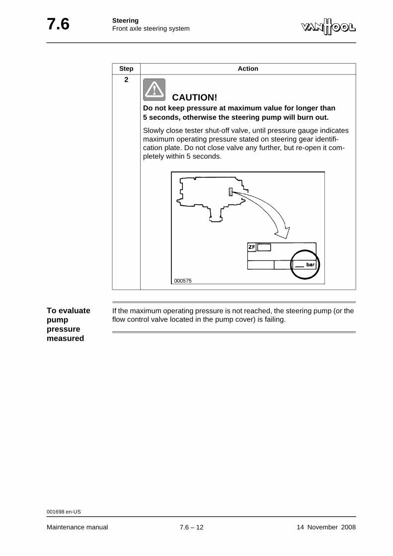
7.6 SteeringFront axle steering system
To evaluate pump pressure measured
If the maximum operating pressure is not reached, the steering pump (or the flow control valve located in the pump cover) is failing.
2
CAUTION!Do not keep pressure at maximum value for longer than 5 seconds, otherwise the steering pump will burn out.
Slowly close tester shut-off valve, until pressure gauge indicates maximum operating pressure stated on steering gear identifi-cation plate. Do not close valve any further, but re-open it com-pletely within 5 seconds.
Step Action
001698 en-US
Maintenance manual 14 November 2008
.
7.6 – 12
SteeringFront axle steering system 7.6
To check steering pump flow
To be carried out when?
At each major inspection of the steering system
Special tools
Checking values
Refer to separate manual of the "Servotest 570" tester.
Equipment condition
• Parking brake applied
• Chocks in front of and behind drive axle wheels
• "Servotest 570" tester connected (follow the instructions under "To connect Servotest 570 tester" in this chapter)
• Steering fluid temperature 50 °C (122 °F)
Procedure
"Servotest 570" tester ZF No. 7418798574
Step Action
1 Let the engine idle.
2 With the shut-off valve of the tester, set the checking pressure listed in the tester manual.
3 Read flow.
4 Compare the measured value to the value prescribed in the manual of the tester.
001699 en-US
14 November 2008 Maintenance manual
.
7.6 – 13

7.6 SteeringFront axle steering system
To check/set hydraulic steering limitation
Introduction If a front wheel were to be turned against the steering stop with full power-assisted pressure, the steering pump and steering mechanism would be damaged due to overstraining. This is why the steering gear has two valves that automatically reduce pressure, just before a road wheel reaches its maximum steering turning angle. It is possible to set the point in time at which these valves open.
To be carried out when?
Refer to "Steering system: to perform major inspection" in chapter 1.1, "Main-tenance schedule".
Special tools
Setting values Refer to "Technical data" at the end of this chapter.
Equipment condition
• Parking brake applied
• Chocks in front of and behind drive axle wheels.
• Steering angle lock angles set correctly, refer to "To check/set steering lock angles" in chapter 12.6.
• Steering fluid temperature between 40 and 60 °C (104 and 140 °F), refer to "To bring steering fluid up to temperature" below.
To bring steering fluid up to temper-ature
You can warm up the steering fluid by running the engine and turning the steering wheel from stop to stop a few times. Measure the temperature in the fluid tank.
NOTE: If you are using the special tester by ZF, you can warm up the fluid quickly by operating the shut-off valve of the tester (refer to "To connect Servotest 570 tester" earlier in this chapter).
Steering wheel puller Van Hool No. 619900910
Torque meter socket with serrations Van Hool No. 10575651
Hose to connect pressure checking gauge
Van Hool No. 639901590
001859 en-US
Maintenance manual 14 November 2008
continued on next page.
7.6 – 14
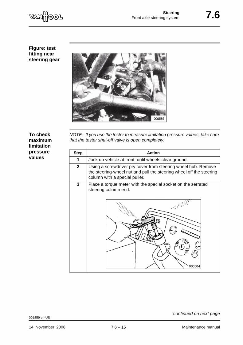
SteeringFront axle steering system 7.6
Figure: test fitting near steering gear
To check maximum limitation pressure values
NOTE: If you use the tester to measure limitation pressure values, take care that the tester shut-off valve is open completely.
Step Action
1 Jack up vehicle at front, until wheels clear ground.
2 Using a screwdriver pry cover from steering wheel hub. Remove the steering-wheel nut and pull the steering wheel off the steering column with a special puller.
3 Place a torque meter with the special socket on the serrated steering column end.
001859 en-US
14 November 2008 Maintenance manual
continued on next page.
7.6 – 15
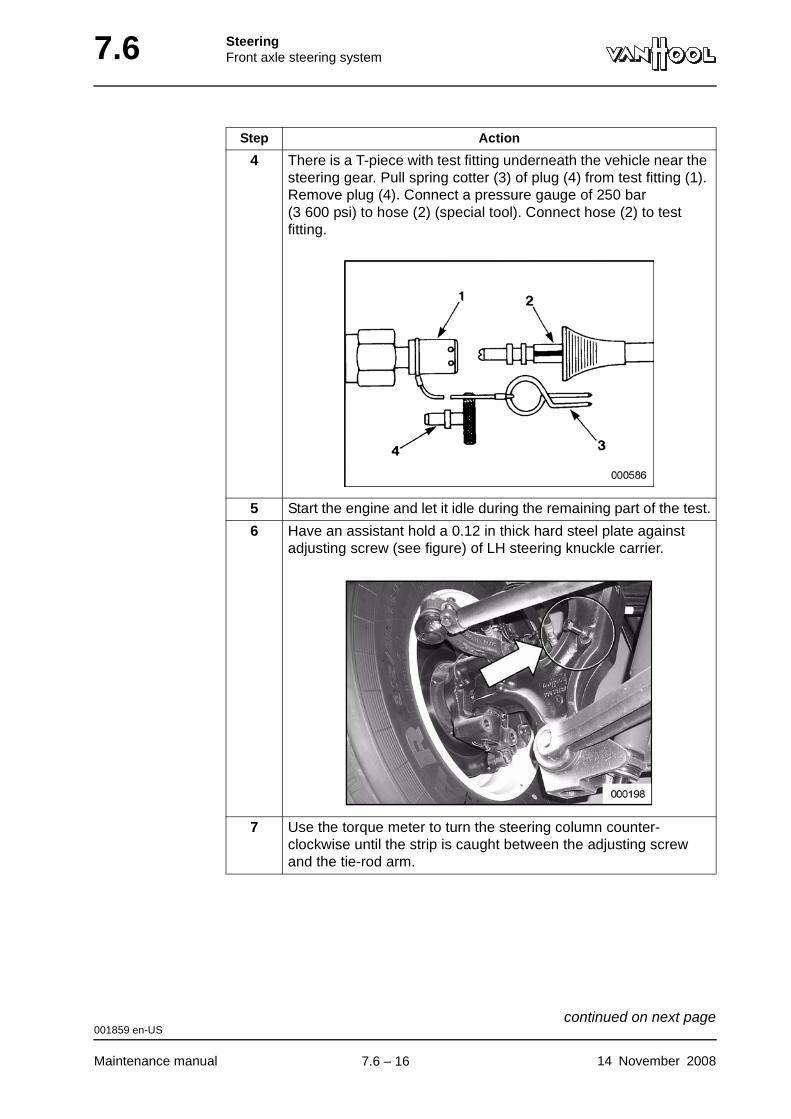
7.6 SteeringFront axle steering system
4 There is a T-piece with test fitting underneath the vehicle near the steering gear. Pull spring cotter (3) of plug (4) from test fitting (1). Remove plug (4). Connect a pressure gauge of 250 bar (3 600 psi) to hose (2) (special tool). Connect hose (2) to test fitting.
5 Start the engine and let it idle during the remaining part of the test.
6 Have an assistant hold a 0.12 in thick hard steel plate against adjusting screw (see figure) of LH steering knuckle carrier.
7 Use the torque meter to turn the steering column counter-clockwise until the strip is caught between the adjusting screw and the tie-rod arm.
Step Action
001859 en-US
Maintenance manual 14 November 2008
continued on next page.
7.6 – 16

SteeringFront axle steering system 7.6
Figure: adjusting screws on steering gear
1 Limiting end-pressure on left turns2 Limiting end-pressure on right turns
To set end limitation pressure values
8
CAUTION!Do not keep steering column end in end-of-travel position for longer than 5 seconds.
Using a torque meter, pull steering column briefly against left end stop at 18 to 36 ft.lbf. and read pressure on pressure gauge.
9 Repeat test for right wheel.
10 Compare measured values with values in technical data.
Step Action
Step Action
1 Let go of steering column end, so that only no-load pressure is still in system.
2 Using a 14 mm wrench, loosen locknut of relevant adjusting screw on steering gear.
3 Turn adjusting screw with 5 mm socket wrench:
• counterclockwise to increase pressure;
• clockwise to reduce pressure.
4 Check whether pressure has changed as described under "To check maximum limitation pressure values".
5 Repeat steps 1 and 3, until prescribed maximum limitation pressure is reached.
001859 en-US
14 November 2008 Maintenance manual
continued on next page.
7.6 – 17
7.6 SteeringFront axle steering system
To check setting
Slowly drive vehicle (with normal load) forward and turn steering wheel clockwise (and a second time counterclockwise as well), until point where power assistance falls out. Some clearance should still remain between the tie-rod arm and the adjusting screw on the steering knuckle carrier.
6 Tighten locknut to prescribed torque without adjusting screw turning as well.
7 Lower front wheels onto ground.
8 Fix the steering wheel in straight-ahead position on the steering column.
9 Turn off engine. Remove pressure gauge and reinstall test fitting plug.
10 Check setting, refer to "To check setting".
Step Action
001859 en-US
Maintenance manual 14 November 2008
.
7.6 – 18
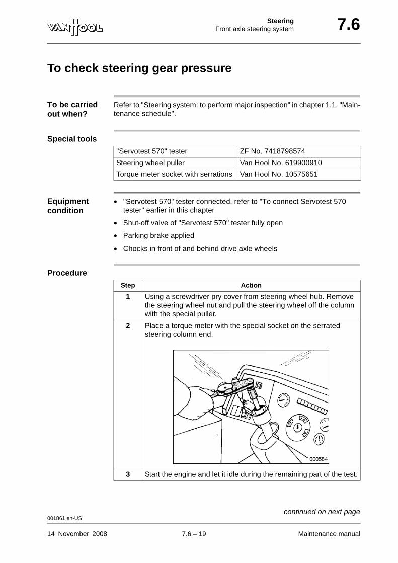
SteeringFront axle steering system 7.6
To check steering gear pressure
To be carried out when?
Refer to "Steering system: to perform major inspection" in chapter 1.1, "Main-tenance schedule".
Special tools
Equipment condition
• "Servotest 570" tester connected, refer to "To connect Servotest 570 tester" earlier in this chapter
• Shut-off valve of "Servotest 570" tester fully open
• Parking brake applied
• Chocks in front of and behind drive axle wheels
Procedure
"Servotest 570" tester ZF No. 7418798574
Steering wheel puller Van Hool No. 619900910
Torque meter socket with serrations Van Hool No. 10575651
Step Action
1 Using a screwdriver pry cover from steering wheel hub. Remove the steering wheel nut and pull the steering wheel off the column with the special puller.
2 Place a torque meter with the special socket on the serrated steering column end.
3 Start the engine and let it idle during the remaining part of the test.
001861 en-US
14 November 2008 Maintenance manual
continued on next page.
7.6 – 19
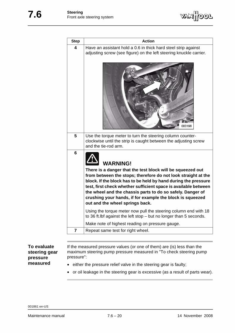
7.6 SteeringFront axle steering system
To evaluate steering gear pressure measured
If the measured pressure values (or one of them) are (is) less than the maximum steering pump pressure measured in "To check steering pump pressure":
• either the pressure relief valve in the steering gear is faulty;
• or oil leakage in the steering gear is excessive (as a result of parts wear).
4 Have an assistant hold a 0.6 in thick hard steel strip against adjusting screw (see figure) on the left steering knuckle carrier.
5 Use the torque meter to turn the steering column counter-clockwise until the strip is caught between the adjusting screw and the tie-rod arm.
6
WARNING!There is a danger that the test block will be squeezed out from between the stops; therefore do not look straight at the block. If the block has to be held by hand during the pressure test, first check whether sufficient space is available between the wheel and the chassis parts to do so safely. Danger of crushing your hands, if for example the block is squeezed out and the wheel springs back.
Using the torque meter now pull the steering column end with 18 to 36 ft.lbf against the left stop – but no longer than 5 seconds.
Make note of highest reading on pressure gauge.
7 Repeat same test for right wheel.
Step Action
001861 en-US
Maintenance manual 14 November 2008
.
7.6 – 20
SteeringFront axle steering system 7.6
To check steering gear for internal leakage
To be carried out when?
Refer to "Steering system: to perform major inspection" in chapter 1.1, "Main-tenance schedule".
Special tools
Checking values
Refer to "Technical data" at the end of this chapter.
Equipment condition
• Vehicle over inspection pit
• "Servotest 570" tester connected, refer to "To connect Servotest 570 tester" earlier in this chapter
• Parking brake applied
• Chocks in front of and behind drive axle wheels
Procedure
"Servotest 570" tester ZF No. 7418798574
Steering wheel puller Van Hool No. 619900910
Torque meter socket with serrations Van Hool No. 10575651
Step Action
1 Using a screwdriver pry cover from steering wheel hub. Remove the steering wheel nut and pull the steering wheel off the column with the special puller.
001862 en-US
14 November 2008 Maintenance manual
continued on next page.
7.6 – 21
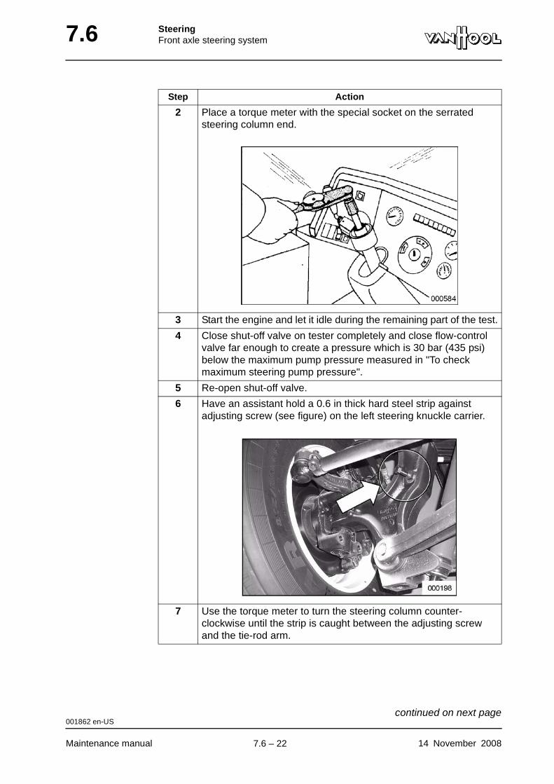
7.6 SteeringFront axle steering system
2 Place a torque meter with the special socket on the serrated steering column end.
3 Start the engine and let it idle during the remaining part of the test.
4 Close shut-off valve on tester completely and close flow-control valve far enough to create a pressure which is 30 bar (435 psi) below the maximum pump pressure measured in "To check maximum steering pump pressure".
5 Re-open shut-off valve.
6 Have an assistant hold a 0.6 in thick hard steel strip against adjusting screw (see figure) on the left steering knuckle carrier.
7 Use the torque meter to turn the steering column counter-clockwise until the strip is caught between the adjusting screw and the tie-rod arm.
Step Action
001862 en-US
Maintenance manual 14 November 2008
continued on next page.
7.6 – 22
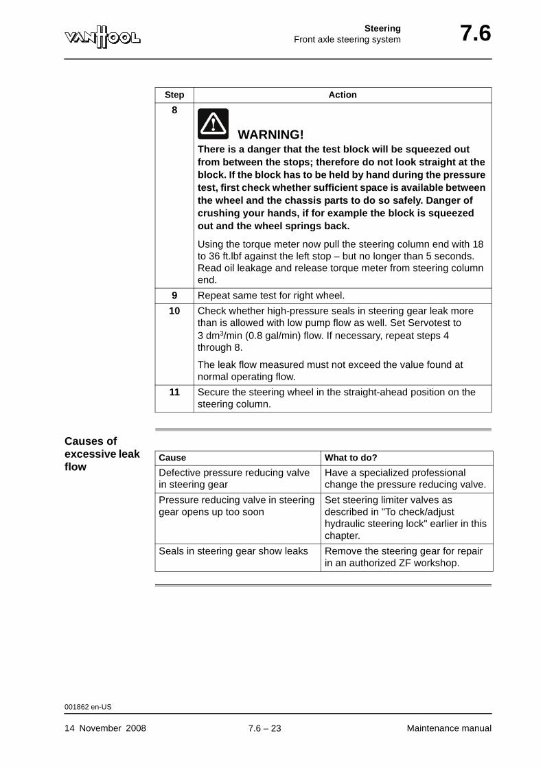
SteeringFront axle steering system 7.6
Causes of excessive leak flow
8
WARNING!There is a danger that the test block will be squeezed out from between the stops; therefore do not look straight at the block. If the block has to be held by hand during the pressure test, first check whether sufficient space is available between the wheel and the chassis parts to do so safely. Danger of crushing your hands, if for example the block is squeezed out and the wheel springs back.
Using the torque meter now pull the steering column end with 18 to 36 ft.lbf against the left stop – but no longer than 5 seconds. Read oil leakage and release torque meter from steering column end.
9 Repeat same test for right wheel.
10 Check whether high-pressure seals in steering gear leak more than is allowed with low pump flow as well. Set Servotest to 3 dm3/min (0.8 gal/min) flow. If necessary, repeat steps 4 through 8.
The leak flow measured must not exceed the value found at normal operating flow.
11 Secure the steering wheel in the straight-ahead position on the steering column.
Step Action
Cause What to do?
Defective pressure reducing valve in steering gear
Have a specialized professional change the pressure reducing valve.
Pressure reducing valve in steering gear opens up too soon
Set steering limiter valves as described in "To check/adjust hydraulic steering lock" earlier in this chapter.
Seals in steering gear show leaks Remove the steering gear for repair in an authorized ZF workshop.
001862 en-US
14 November 2008 Maintenance manual
.
7.6 – 23
7.6 SteeringFront axle steering system
To check return time of power steering valve
To be carried out when?
At each major inspection of the steering system
Special tools
Checking values
Refer to "Technical data" at the end of this chapter.
Equipment condition
• Parking brake applied
• Chocks in front of and behind drive axle wheels
• "Servotest 570" tester connected (follow the instructions under "To connect Servotest 570 tester" in this chapter)
• Steering fluid temperature 50 °C (122 °F)
Procedure
"Servotest 570" tester ZF No. 7418798574
Step Action
1 Block pitman arm in mid-position.
2 Start the engine and let it idle during the remaining part of the test.
3 Turn steering wheel to close power steering valve in steering gear, i.e. until maximum pump pressure is being reached on pressure gauge.
4 Slowly release steering wheel, until pressure gauge pointer indi-cates no-load pressure.
5 Use shut-off valve of tester to set pressure that is 10 bar (145 psi) higher than no-load pressure.
6 Release steering wheel.
Power steering valve must return to neutral position within 1 second. In other words, pressure must drop within that time to a value not excessive of 0.5 bar (7.25 psi) above no-load pressure.
001307 en-US
Maintenance manual 14 November 2008
.
7.6 – 24
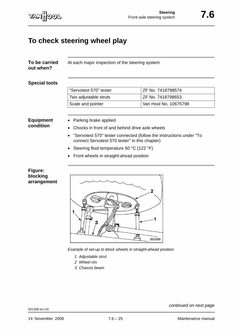
SteeringFront axle steering system 7.6
To check steering wheel play
To be carried out when?
At each major inspection of the steering system
Special tools
Equipment condition
• Parking brake applied
• Chocks in front of and behind drive axle wheels
• "Servotest 570" tester connected (follow the instructions under "To connect Servotest 570 tester" in this chapter)
• Steering fluid temperature 50 °C (122 °F)
• Front wheels in straight-ahead position
Figure: blocking arrangement
Example of set-up to block wheels in straight-ahead position
1 Adjustable strut2 Wheel rim3 Chassis beam
"Servotest 570" tester ZF No. 7418798574
Two adjustable struts ZF No. 7418798653
Scale and pointer Van Hool No. 10675798
001308 en-US
14 November 2008 Maintenance manual
continued on next page.
7.6 – 25
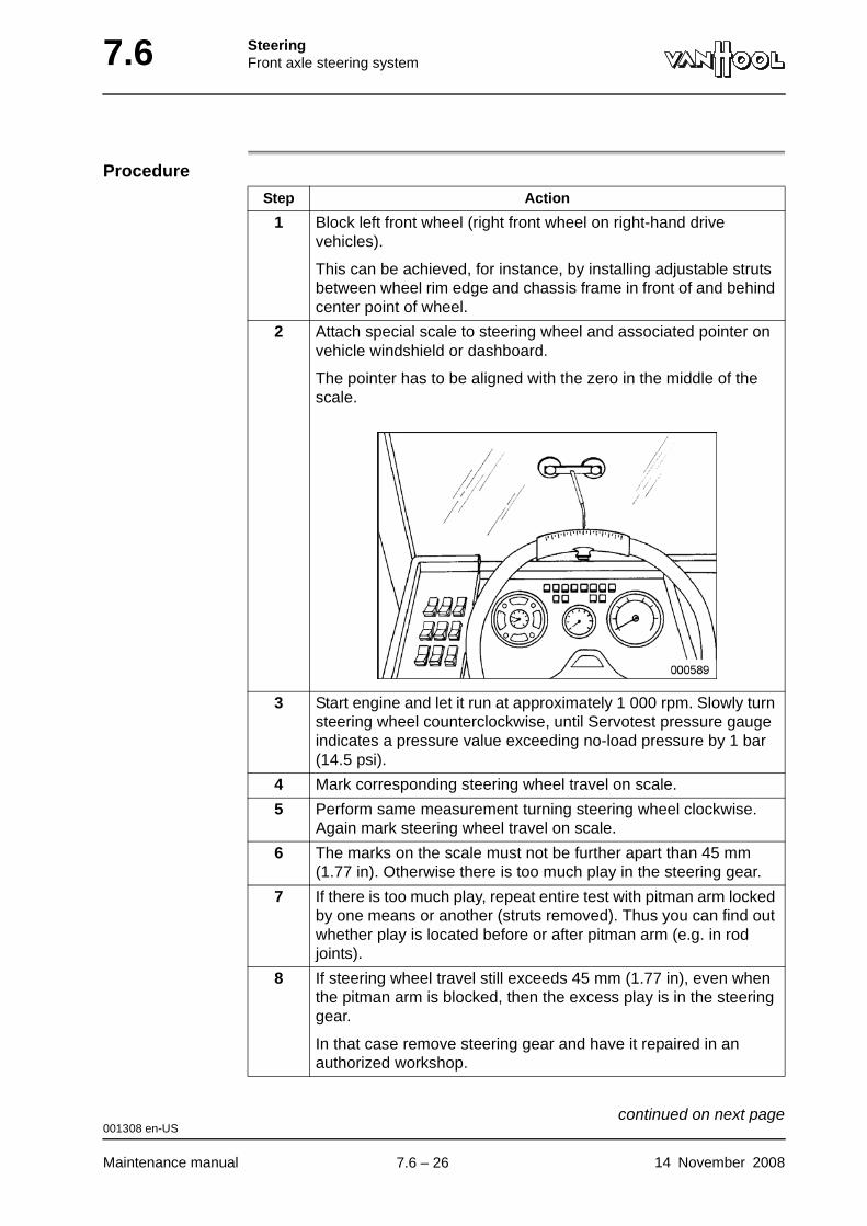
7.6 SteeringFront axle steering system
Procedure
Step Action
1 Block left front wheel (right front wheel on right-hand drive vehicles).
This can be achieved, for instance, by installing adjustable struts between wheel rim edge and chassis frame in front of and behind center point of wheel.
2 Attach special scale to steering wheel and associated pointer on vehicle windshield or dashboard.
The pointer has to be aligned with the zero in the middle of the scale.
3 Start engine and let it run at approximately 1 000 rpm. Slowly turn steering wheel counterclockwise, until Servotest pressure gauge indicates a pressure value exceeding no-load pressure by 1 bar (14.5 psi).
4 Mark corresponding steering wheel travel on scale.
5 Perform same measurement turning steering wheel clockwise. Again mark steering wheel travel on scale.
6 The marks on the scale must not be further apart than 45 mm (1.77 in). Otherwise there is too much play in the steering gear.
7 If there is too much play, repeat entire test with pitman arm locked by one means or another (struts removed). Thus you can find out whether play is located before or after pitman arm (e.g. in rod joints).
8 If steering wheel travel still exceeds 45 mm (1.77 in), even when the pitman arm is blocked, then the excess play is in the steering gear.
In that case remove steering gear and have it repaired in an authorized workshop.
001308 en-US
Maintenance manual 14 November 2008
continued on next page.
7.6 – 26

SteeringFront axle steering system 7.6
Greater play without power assistance
To avoid any misunderstandings it must be mentioned that steering wheel play is always far greater, when the wheel is turned without power assistance than when turned with power assistance. This becomes apparent, when the vehicle is being towed with the engine off.
001308 en-US
14 November 2008 Maintenance manual
.
7.6 – 27
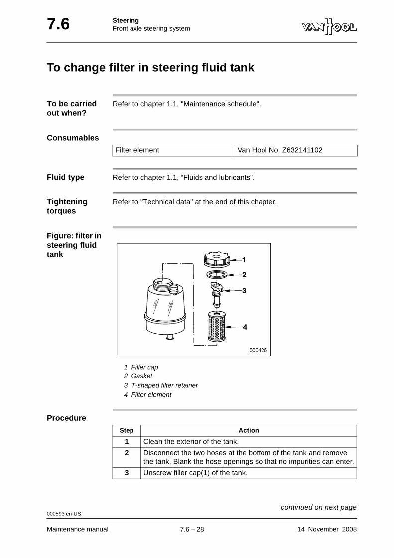
7.6 SteeringFront axle steering system
To change filter in steering fluid tank
To be carried out when?
Refer to chapter 1.1, "Maintenance schedule".
Consumables
Fluid type Refer to chapter 1.1, “Fluids and lubricants”.
Tightening torques
Refer to "Technical data" at the end of this chapter.
Figure: filter in steering fluid tank
1 Filler cap2 Gasket3 T-shaped filter retainer4 Filter element
Procedure
Filter element Van Hool No. Z632141102
Step Action
1 Clean the exterior of the tank.
2 Disconnect the two hoses at the bottom of the tank and remove the tank. Blank the hose openings so that no impurities can enter.
3 Unscrew filler cap(1) of the tank.
000593 en-US
Maintenance manual 14 November 2008
continued on next page.
7.6 – 28
SteeringFront axle steering system 7.6
4 Twist T-shaped filter retainer (3) a quarter of a turn to release filter (4).
5 Lift the filter element from the tank and pull on the retainer to detach it from the filter element.
6 Empty the tank and thoroughly clean its interior.
7 Fit the retainer to the new element and engage the filter assembly on the seat in the tank.
8 Check gasket (2) and install the filler cap.
9 Install the tank and attach the hoses. Tighten the hose clamp screws to the prescribed torque.
10 Fill the tank up to the prescribed level with the recommended fluid.
Step Action
000593 en-US
14 November 2008 Maintenance manual
.
7.6 – 29
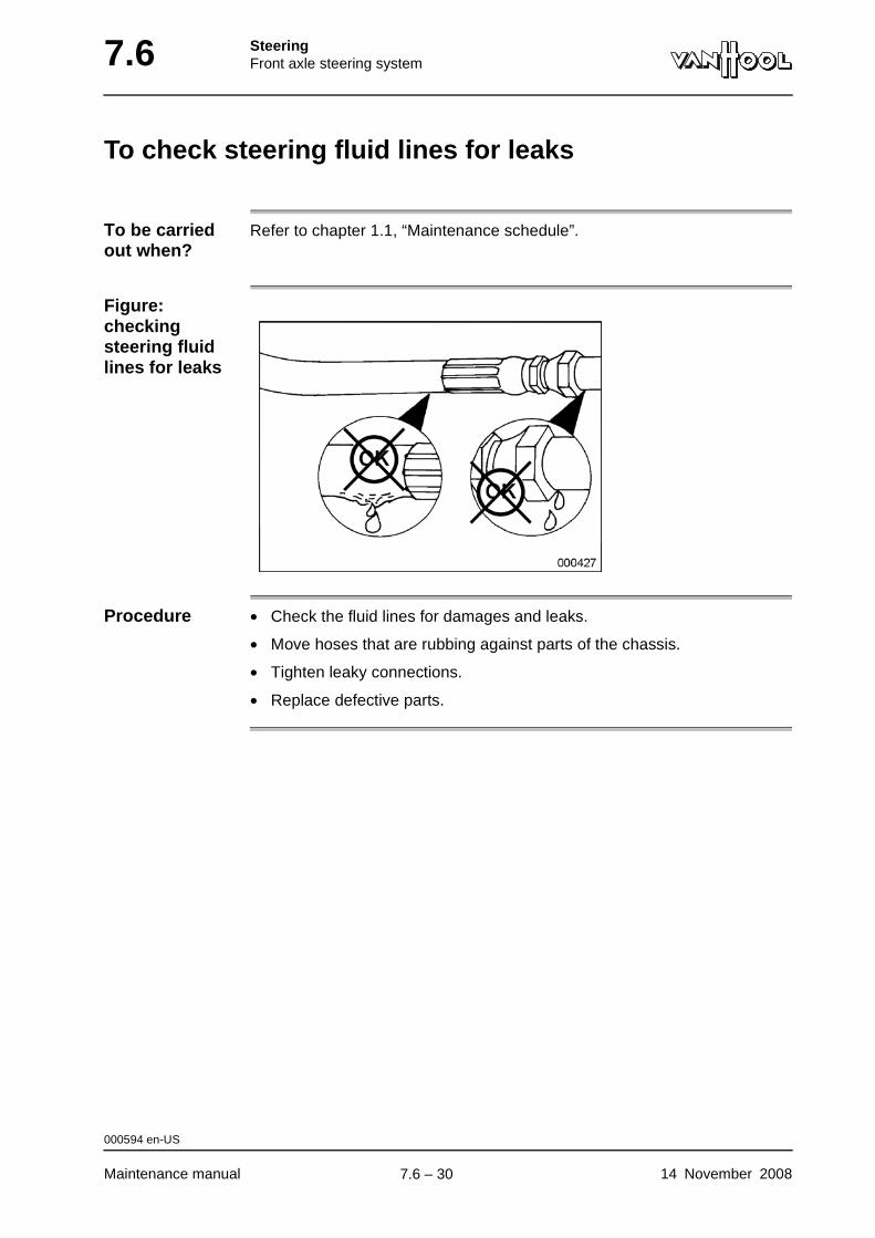
7.6 SteeringFront axle steering system
To check steering fluid lines for leaks
To be carried out when?
Refer to chapter 1.1, “Maintenance schedule”.
Figure: checking steering fluid lines for leaks
Procedure • Check the fluid lines for damages and leaks.
• Move hoses that are rubbing against parts of the chassis.
• Tighten leaky connections.
• Replace defective parts.
000594 en-US
Maintenance manual 14 November 2008
.
7.6 – 30
SteeringFront axle steering system 7.6
To check security of steering gear, rods and levers
To be carried out when?
Refer to chapter 1.1, "Maintenance schedule".
Tightening torques
Refer to "Technical data" at the end of this chapter.
WARNING!Never retighten nuts or screws fitted with locking adhesive or "micro-encapsulated" nuts or screws, since this will destroy their locking prop-erties. Once they have been removed, micro-encapsulated screws must not be reused.
How to check? Visually check bolts, screws and nuts that are locked by means of a cotter pin, liquid adhesive (Loctite), staking or "micro-encapsulation". The security of all others must be checked mechanically. Retighten, if necessary.
000595 en-US
14 November 2008 Maintenance manual
.
7.6 – 31
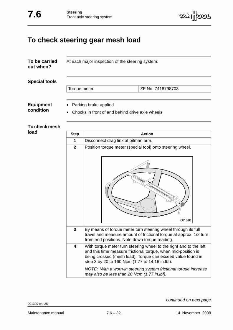
7.6 SteeringFront axle steering system
To check steering gear mesh load
To be carried out when?
At each major inspection of the steering system.
Special tools
Equipment condition
• Parking brake applied
• Chocks in front of and behind drive axle wheels
To check mesh load
Torque meter ZF No. 7418798703
Step Action
1 Disconnect drag link at pitman arm.
2 Position torque meter (special tool) onto steering wheel.
3 By means of torque meter turn steering wheel through its full travel and measure amount of frictional torque at approx. 1/2 turn from end positions. Note down torque reading.
4 With torque meter turn steering wheel to the right and to the left and this time measure frictional torque, when mid-position is being crossed (mesh load). Torque can exceed value found in step 3 by 20 to 160 Ncm (1.77 to 14.16 in.lbf).
NOTE: With a worn-in steering system frictional torque increase may also be less than 20 Ncm (1.77 in.lbf).
001309 en-US
Maintenance manual 14 November 2008
continued on next page.
7.6 – 32
SteeringFront axle steering system 7.6
To adjust mesh load
Steering gear mesh load can be adjusted with steering gear removed only (have steering gear removed in ZF workshop).
001309 en-US
14 November 2008 Maintenance manual
.
7.6 – 33
7.6 SteeringFront axle steering system
To dismantle steering gear
WARNING!The steering gear should be dismantled or repaired at ZF authorized workshops only. They have original spare parts and appropriate tools at their disposal, as well as the necessary know-how.
000740 en-US
Maintenance manual 14 November 2008
.
7.6 – 34
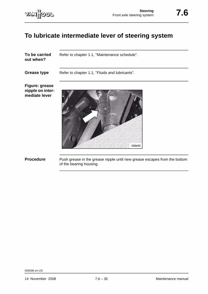
SteeringFront axle steering system 7.6
To lubricate intermediate lever of steering system
To be carried out when?
Refer to chapter 1.1, "Maintenance schedule".
Grease type Refer to chapter 1.1, "Fluids and lubricants".
Figure: grease nipple on inter-mediate lever
Procedure Push grease in the grease nipple until new grease escapes from the bottom of the bearing housing.
000596 en-US
14 November 2008 Maintenance manual
.
7.6 – 35
7.6 SteeringFront axle steering system
To check linkage joints
To be carried out when?
Refer to chapter 1.1, "Maintenance schedule".
Equipment condition
Exterior of joint that is to be checked must have been cleaned with a dry cloth or cotton waste
To check what?
• joint exterior for corrosion
• dust cover of steering linkage joint
• dust cover retaining rings
• joint for play
CAUTION!Do not damage ball-joint dust cover. Do not use any detergents or sol-vents.
CAUTION!Water entering the ball-joint through an untight dust cover will damage the joint in no time.
000597 en-US
Maintenance manual 14 November 2008
continued on next page.
7.6 – 36
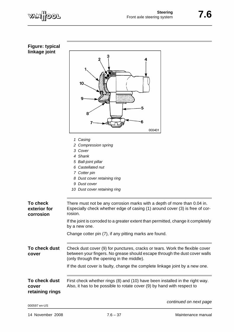
SteeringFront axle steering system 7.6
Figure: typical linkage joint
1 Casing2 Compression spring3 Cover4 Shank5 Ball-joint pillar6 Castellated nut7 Cotter pin8 Dust cover retaining ring9 Dust cover
10 Dust cover retaining ring
To check exterior for corrosion
There must not be any corrosion marks with a depth of more than 0.04 in. Especially check whether edge of casing (1) around cover (3) is free of cor-rosion.
If the joint is corroded to a greater extent than permitted, change it completely by a new one.
Change cotter pin (7), if any pitting marks are found.
To check dust cover
Check dust cover (9) for punctures, cracks or tears. Work the flexible cover between your fingers. No grease should escape through the dust cover walls (only through the opening in the middle).
If the dust cover is faulty, change the complete linkage joint by a new one.
To check dust cover retaining rings
First check whether rings (8) and (10) have been installed in the right way. Also, it has to be possible to rotate cover (9) by hand with respect to
000597 en-US
14 November 2008 Maintenance manual
continued on next page.
7.6 – 37
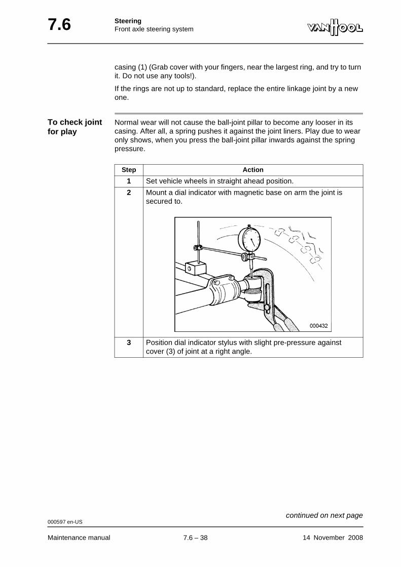
7.6 SteeringFront axle steering system
casing (1) (Grab cover with your fingers, near the largest ring, and try to turn it. Do not use any tools!).
If the rings are not up to standard, replace the entire linkage joint by a new one.
To check joint for play
Normal wear will not cause the ball-joint pillar to become any looser in its casing. After all, a spring pushes it against the joint liners. Play due to wear only shows, when you press the ball-joint pillar inwards against the spring pressure.
Step Action
1 Set vehicle wheels in straight ahead position.
2 Mount a dial indicator with magnetic base on arm the joint is secured to.
3 Position dial indicator stylus with slight pre-pressure against cover (3) of joint at a right angle.
000597 en-US
Maintenance manual 14 November 2008
continued on next page.
7.6 – 38
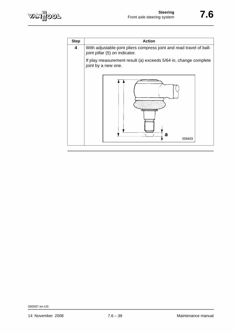
SteeringFront axle steering system 7.6
4 With adjustable-joint pliers compress joint and read travel of ball-joint pillar (5) on indicator.
If play measurement result (a) exceeds 5/64 in, change complete joint by a new one.
Step Action
000597 en-US
14 November 2008 Maintenance manual
.
7.6 – 39
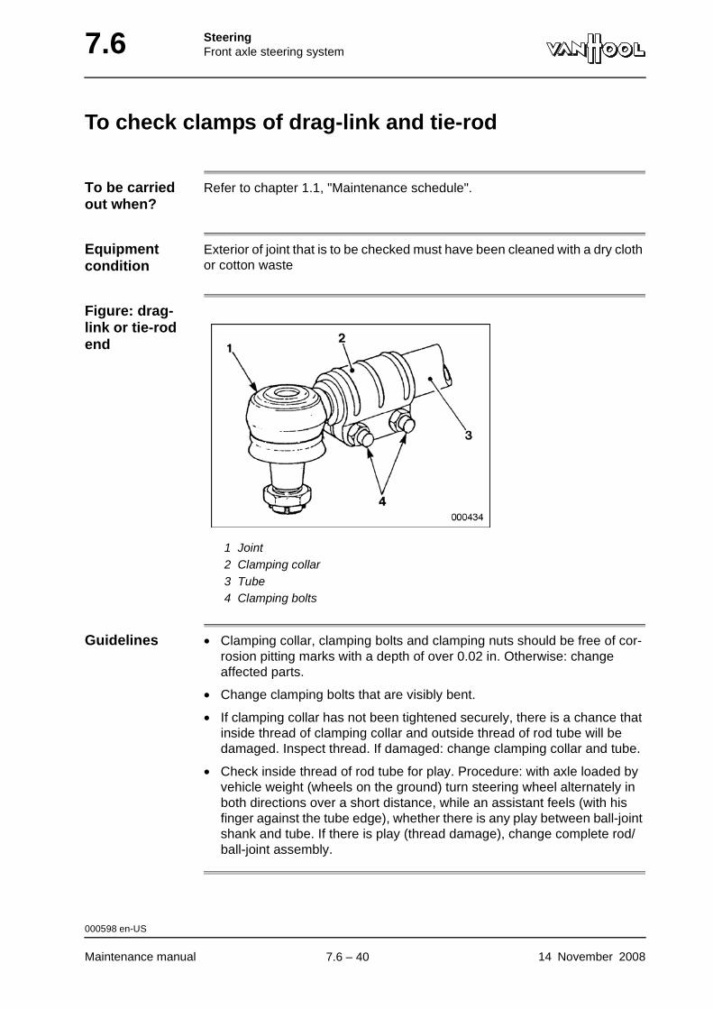
7.6 SteeringFront axle steering system
To check clamps of drag-link and tie-rod
To be carried out when?
Refer to chapter 1.1, "Maintenance schedule".
Equipment condition
Exterior of joint that is to be checked must have been cleaned with a dry cloth or cotton waste
Figure: drag-link or tie-rod end
1 Joint2 Clamping collar3 Tube4 Clamping bolts
Guidelines • Clamping collar, clamping bolts and clamping nuts should be free of cor-rosion pitting marks with a depth of over 0.02 in. Otherwise: change affected parts.
• Change clamping bolts that are visibly bent.
• If clamping collar has not been tightened securely, there is a chance that inside thread of clamping collar and outside thread of rod tube will be damaged. Inspect thread. If damaged: change clamping collar and tube.
• Check inside thread of rod tube for play. Procedure: with axle loaded by vehicle weight (wheels on the ground) turn steering wheel alternately in both directions over a short distance, while an assistant feels (with his finger against the tube edge), whether there is any play between ball-joint shank and tube. If there is play (thread damage), change complete rod/ball-joint assembly.
000598 en-US
Maintenance manual 14 November 2008
.
7.6 – 40
SteeringFront axle steering system 7.6
To check drag-link and tie-rod tubes
To be carried out when?
Refer to chapter 1.1, “Maintenance schedule”.
WARNING!It is not permitted to straighten a bent drag-link or tie rod.
Procedure Visually check rod tube for deformation and damage.
Change the tube if you can see that it is not in proper condition.
000747 en-US
14 November 2008 Maintenance manual
.
7.6 – 41
7.6 SteeringFront axle steering system
To check straight-ahead position of wheels
To be carried out when?
Refer to "Steering system: to perform major inspection” in chapter 1.1, "Main-tenance schedule".
Equipment condition
• Parking brake applied
• Chocks in front of and behind wheels of drive axle
• Vehicle jacked up at the front
WARNING!If it is found that the straight-ahead position is out of adjustment, examine the complete steering system closely for deformation and cracks (impact damage). Remove the pitman arm with a special puller and check the pitman-arm shaft taper serrations. If they are no longer dead straight, the pitman-arm shaft is distorted. If there is the slightest indication of any defect, immediately change those parts. On no account must bent or twisted parts be straightened for re-use.
Procedure
Step Action
1 Turn the steering wheel from lock to lock and count the number of revolutions.
2 Turn back half the number of revolutions and align the mark on the steering gear input shaft with the mark on the steering gear housing.
3 Check whether the front wheels are exactly aligned with the wheels of the drive axle (if necessary, approximate, by laying a straight ruler along the wheels at each side of the vehicle). Do take the toe into account.
If the front wheels deviate excessively from the straight-ahead position, the drag-link is too long or too short.
4 If necessary, adjust the length of the drag link by loosening the clamps from the rod ends and turning the rod tube the correct direction.
5 Also check the play in the steering gear as described in "To check steering wheel play".
000741 en-US
Maintenance manual 14 November 2008
.
7.6 – 42
SteeringFront axle steering system 7.6
To check maximum steering lock angles
To be carried out when?
At each major inspection of the steering system.
Procedure Refer to chapter 12.6 "To check/adjust steering lock angles".
000742 en-US
14 November 2008 Maintenance manual
.
7.6 – 43
7.6 SteeringFront axle steering system
To check steering column bearings for play
To be carried out when?
At each major inspection of the steering system.
Procedure Alternately push and pull steering wheel.
If too much play is felt, have steering column bearings renewed.
000744 en-US
Maintenance manual 14 November 2008
.
7.6 – 44
SteeringFront axle steering system 7.6
To check universal joints and flex couplings
To be carried out when?
At each major inspection of the steering system.
Procedure Turn steering wheel alternately to the right and to the left, while assistant watches joints.
Joints that "clack" (indicating play) or bind have to be renewed.
000745 en-US
14 November 2008 Maintenance manual
.
7.6 – 45
7.6 SteeringFront axle steering system
To remove steering assembly
Equipment condition
• Vehicle over inspection pit
• Parking brake applied
• Steering fluid drained, refer to "To change fluid of power steering system"
To remove steering gear
WARNING!The steering gear weighs approximately 90 lbs. Support it in a safe manner, before undoing its fixing screws.
To disconnect pitman arm
WARNING!Do not under any circumstances hammer pitman arm to break it loose from its shaft, nor drive a wedge between pitman arm and steering gear. To do so can cause serious internal damage to the steering gear. Equally, do not attempt to free the pitman arm by heating it with a blow-torch. The heat affects the metal structure of the pitman arm, thus cre-ating a risk of potential catastrophic failure.
The pitman arm has to be removed with a special puller.
To remove steering wheel center trim
To remove steering wheel center trim, simply pry it out with a screwdriver.
002403 en-US
Maintenance manual 14 November 2008
.
7.6 – 46
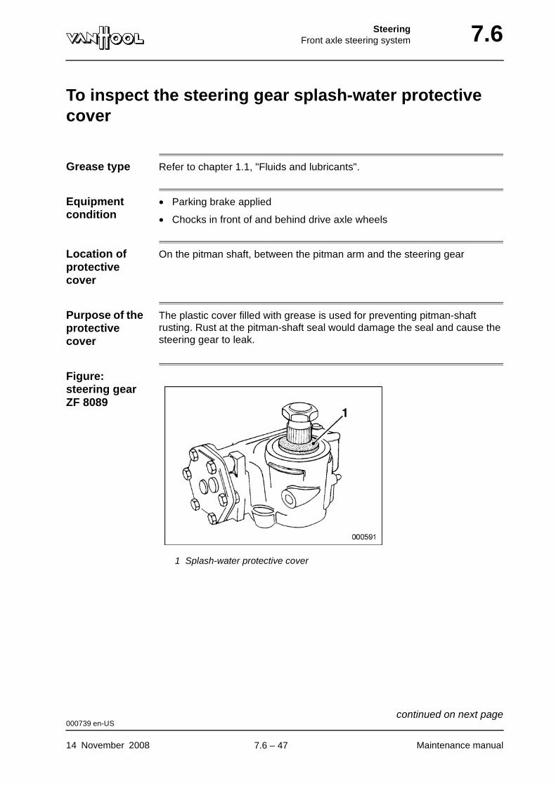
SteeringFront axle steering system 7.6
To inspect the steering gear splash-water protective cover
Grease type Refer to chapter 1.1, "Fluids and lubricants".
Equipment condition
• Parking brake applied
• Chocks in front of and behind drive axle wheels
Location of protective cover
On the pitman shaft, between the pitman arm and the steering gear
Purpose of the protective cover
The plastic cover filled with grease is used for preventing pitman-shaft rusting. Rust at the pitman-shaft seal would damage the seal and cause the steering gear to leak.
Figure: steering gear ZF 8089
1 Splash-water protective cover
000739 en-US
14 November 2008 Maintenance manual
continued on next page.
7.6 – 47

7.6 SteeringFront axle steering system
Procedure
WARNING!Do not under any circumstances hammer pitman arm to break it loose from its shaft, nor drive a wedge between pitman arm and steering gear. To do so can cause serious internal damage to the steering gear. Equally, do not attempt to free the pitman arm by heating it with a blow-torch. The heat affects the metal structure of the pitman arm, thus cre-ating a risk of potential catastrophic failure.
Step Action
1 Remove the pitman arm with a special puller.
2 Inspect the cover and replace it when damaged or worn.
NOTE: Fill the space inside the new cover completely with the specified grease.
000739 en-US
Maintenance manual 14 November 2008
.
7.6 – 48

SteeringFront axle steering system 7.6
Technical data: front axle steering system
Hydraulic circuit
Tightening torques
Maximum pressure 170 + 10 bar (2 466 + 145 psi)
No-load pressure 4 bar (58 psi)
Steering limiter valve relief pressure 50 to 60 bar (725 to 870 psi) at a fluid temperature of 50 ± 10 °C (122 ± 18 °F)
Steering gear internal leakage rate Maximum 2.5 dm3/min (0.66 gal/min)
Standard hose clamps, clamping range up to 0.9 in dia. 2.2 ± 0.4 ft.lbf
Standard hose clamps, clamping range up to 1.06 in dia.
3.3 + 0.4 ft.lbf
Constant torque hose clamps (manufacturer "Breeze"), with four conical spring washers
5.2 ± 0.4 ft.lbf
Constant torque hose clamps (manufacturer "Breeze"), with five conical spring washers
6.6 + 0.7 ft.lbf
Limiter valve adjuster locknuts 15 + 7 ft.lbf
004999 en-US
14 November 2008 Maintenance manual
continued on next page.
7.6 – 49
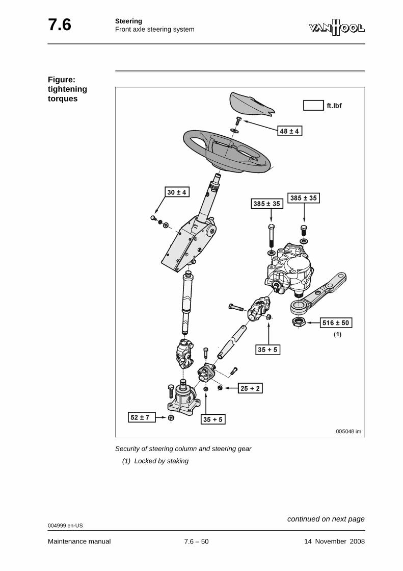
7.6 SteeringFront axle steering system
Figure: tightening torques
Security of steering column and steering gear
(1) Locked by staking
004999 en-US
Maintenance manual 14 November 2008
continued on next page.
7.6 – 50
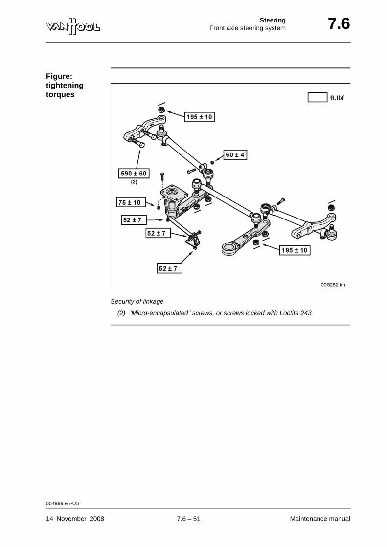
SteeringFront axle steering system 7.6
Figure: tightening torques
Security of linkage
(2) "Micro-encapsulated" screws, or screws locked with Loctite 243
004999 en-US
14 November 2008 Maintenance manual
.
7.6 – 51
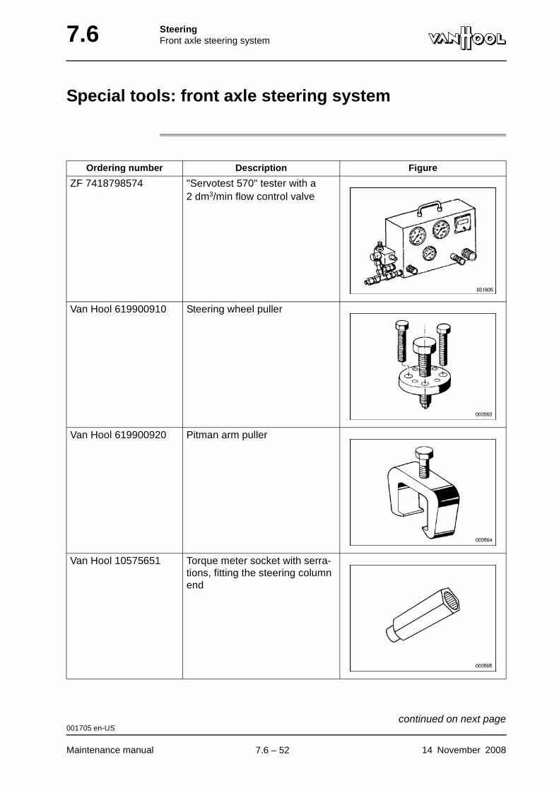
7.6 SteeringFront axle steering system
Special tools: front axle steering system
Ordering number Description Figure
ZF 7418798574 "Servotest 570" tester with a 2 dm3/min flow control valve
Van Hool 619900910 Steering wheel puller
Van Hool 619900920 Pitman arm puller
Van Hool 10575651 Torque meter socket with serra-tions, fitting the steering column end
001705 en-US
Maintenance manual 14 November 2008
continued on next page.
7.6 – 52
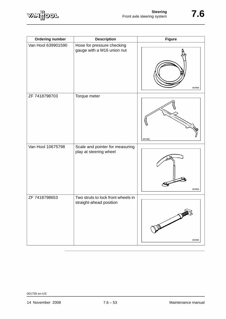
SteeringFront axle steering system 7.6
Van Hool 639901590 Hose for pressure checking gauge with a M16 union nut
ZF 7418798703 Torque meter
Van Hool 10675798 Scale and pointer for measuring play at steering wheel
ZF 7418798653 Two struts to lock front wheels in straight-ahead position
Ordering number Description Figure
001705 en-US
14 November 2008 Maintenance manual
.
7.6 – 53

7.6 SteeringFront axle steering system
This page has been intentionally left blank.
001705 en-US
Maintenance manual 14 November 20087.6 – 54

Part 8 - Climate control
Overview
Contents
Chapter See page
Chapter 2: Control systems 8.2-1
Chapter 6: Airside systems 8.6-1
Chapter 10: Water circuit 8.10-1
Chapter 14: Refrigerant circuit 8.14-1

Climate controlControl systems 8.2
Chapter 2: Control systems
Overview
Introduction This chapter deals with the control system.
Number of pages
38
Chapter publi-cation date
14 November 2008
Contents
Topic See page
Driver's cab control system: layout 8.2-2
Driver's cab control system: visual identification of compo-nents
8.2-3
Driver's cab control system: operation 8.2-5
Driver's cab control system: component location 8.2-7
Passenger compartment control system: layout 8.2-9
Passenger compartment control system: visual identifi-cation of components
8.2-11
Passenger compartment control system: operation 8.2-14
Passenger compartment control system: component location
8.2-22
Passenger compartment control system: to troubleshoot using the multifunctional display
8.2-25
Passenger compartment control system: to activate the "engine running" simulation
8.2-28
Passenger compartment control system: to call up tempera-tures
8.2-30
Passenger compartment control system: to set temperature 8.2-32
Passenger compartment control system: to check tempe-rature sensors
8.2-35
Technical data: control system 8.2-37
14 November 2008 Maintenance manual
.
8.2 – 1
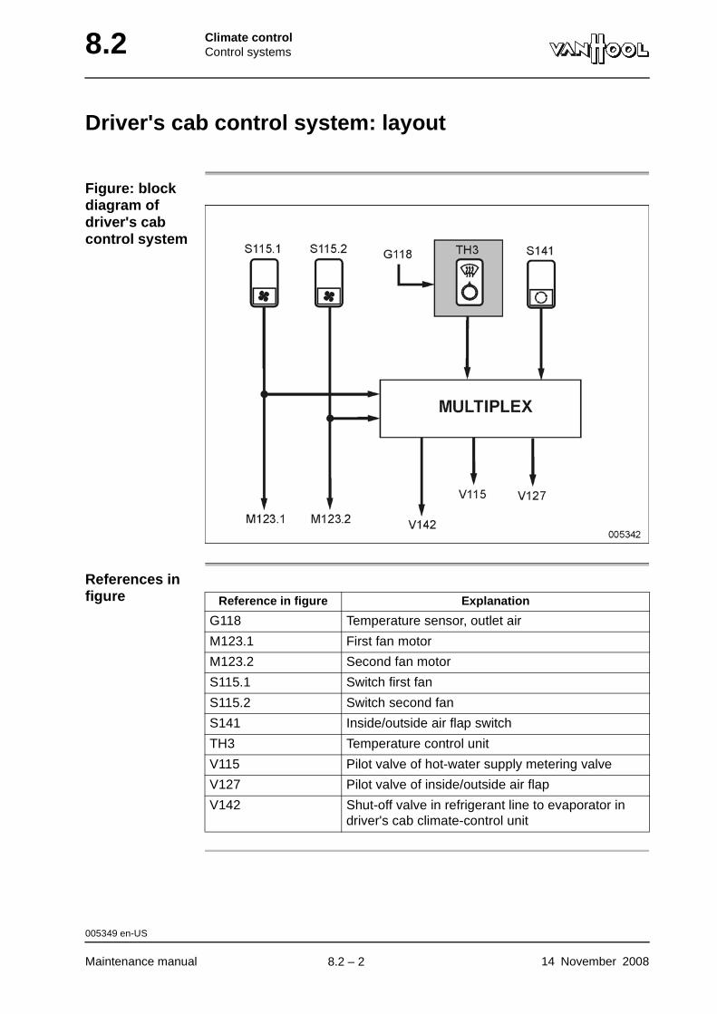
8.2 Climate controlControl systems
Driver's cab control system: layout
Figure: block diagram of driver's cab control system
References in figure Reference in figure Explanation
G118 Temperature sensor, outlet air
M123.1 First fan motor
M123.2 Second fan motor
S115.1 Switch first fan
S115.2 Switch second fan
S141 Inside/outside air flap switch
TH3 Temperature control unit
V115 Pilot valve of hot-water supply metering valve
V127 Pilot valve of inside/outside air flap
V142 Shut-off valve in refrigerant line to evaporator in driver's cab climate-control unit
005349 en-US
Maintenance manual 14 November 2008
.
8.2 – 2
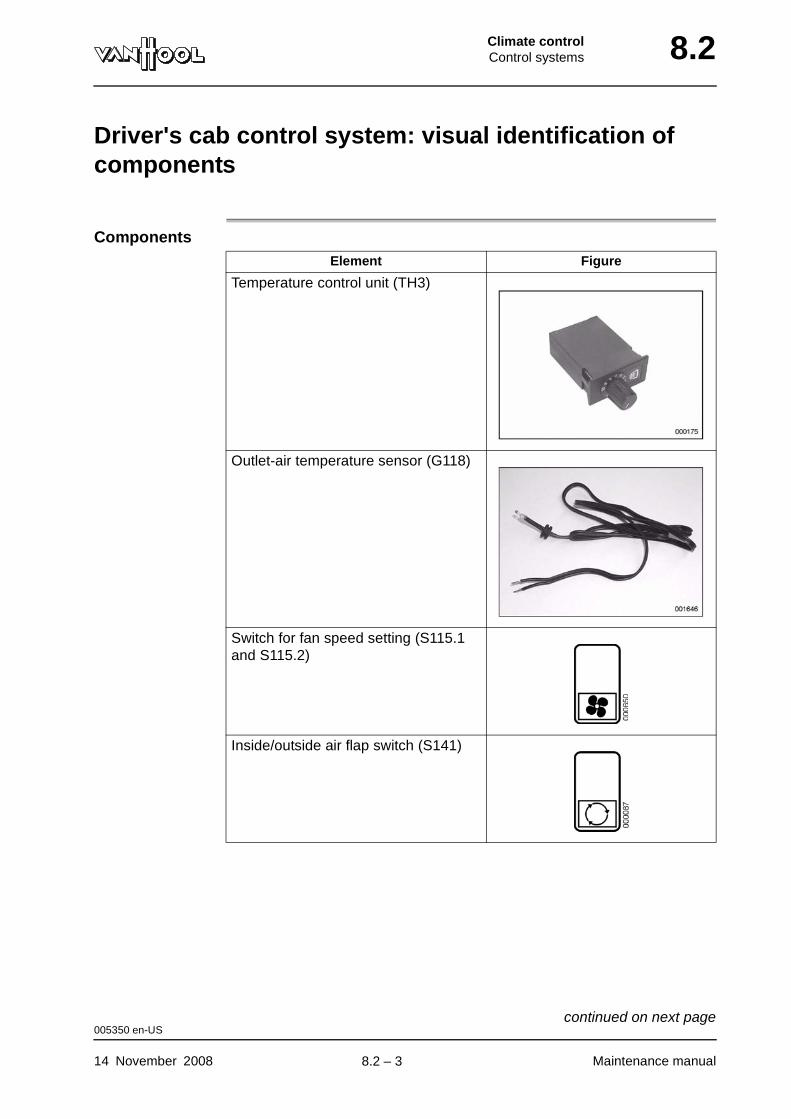
Climate controlControl systems 8.2
Driver's cab control system: visual identification of components
ComponentsElement Figure
Temperature control unit (TH3)
Outlet-air temperature sensor (G118)
Switch for fan speed setting (S115.1 and S115.2)
Inside/outside air flap switch (S141)
005350 en-US
14 November 2008 Maintenance manual
continued on next page.
8.2 – 3
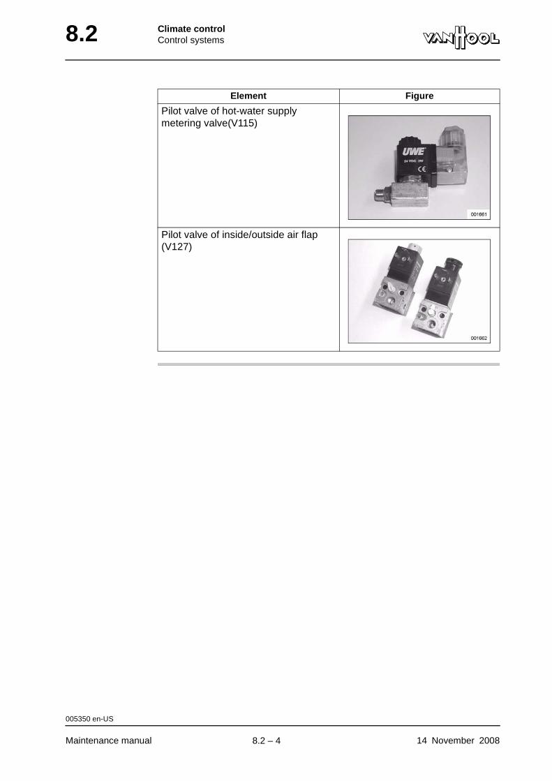
8.2 Climate controlControl systems
Pilot valve of hot-water supply metering valve(V115)
Pilot valve of inside/outside air flap (V127)
Element Figure
005350 en-US
Maintenance manual 14 November 2008
.
8.2 – 4
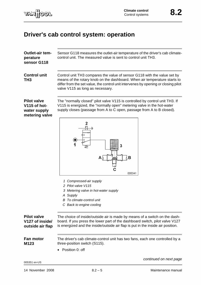
Climate controlControl systems 8.2
Driver's cab control system: operation
Outlet-air tem-perature sensor G118
Sensor G118 measures the outlet-air temperature of the driver's cab climate-control unit. The measured value is sent to control unit TH3.
Control unit TH3
Control unit TH3 compares the value of sensor G118 with the value set by means of the rotary knob on the dashboard. When air temperature starts to differ from the set value, the control unit intervenes by opening or closing pilot valve V115 as long as necessary.
Pilot valve V115 of hot-water supply metering valve
The "normally closed" pilot valve V115 is controlled by control unit TH3. If V115 is energized, the "normally open" metering valve in the hot-water supply closes (passage from A to C open, passage from A to B closed).
1 Compressed-air supply2 Pilot valve V1153 Metering valve in hot-water supplyA SupplyB To climate-control unitC Back to engine cooling
Pilot valve V127 of inside/outside air flap
The choice of inside/outside air is made by means of a switch on the dash-board. If you press the lower part of the dashboard switch, pilot valve V127 is energized and the inside/outside air flap is put in the inside air position.
Fan motor M123
The driver's cab climate-control unit has two fans, each one controlled by a three-position switch (S115).
• Position 0: off
005351 en-US
14 November 2008 Maintenance manual
continued on next page.
8.2 – 5
8.2 Climate controlControl systems
• Position 1: low speed
• Position 2: high speed
Shut-off valve V142 in refrig-erant circuit
The "normally closed" solenoid shut-off valve V142 is controlled by the pas-senger compartment control system (refer to "Passenger compartment control system: operation"). The climate control program prevents the shut-off valve from opening with fan motor stopped.
005351 en-US
Maintenance manual 14 November 2008
.
8.2 – 6
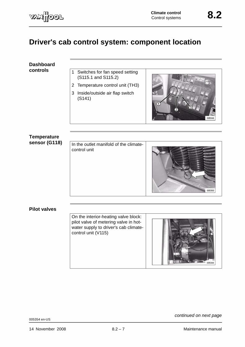
Climate controlControl systems 8.2
Driver's cab control system: component location
Dashboard controls
Temperature sensor (G118)
Pilot valves
1 Switches for fan speed setting (S115.1 and S115.2)
2 Temperature control unit (TH3)
3 Inside/outside air flap switch (S141)
In the outlet manifold of the climate-control unit
On the interior-heating valve block: pilot valve of metering valve in hot-water supply to driver's cab climate-control unit (V115)
005354 en-US
14 November 2008 Maintenance manual
continued on next page.
8.2 – 7
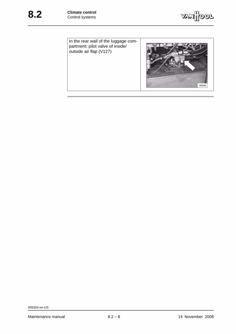
8.2 Climate controlControl systems
In the rear wall of the luggage com-partment: pilot valve of inside/outside air flap (V127)
005354 en-US
Maintenance manual 14 November 2008
.
8.2 – 8
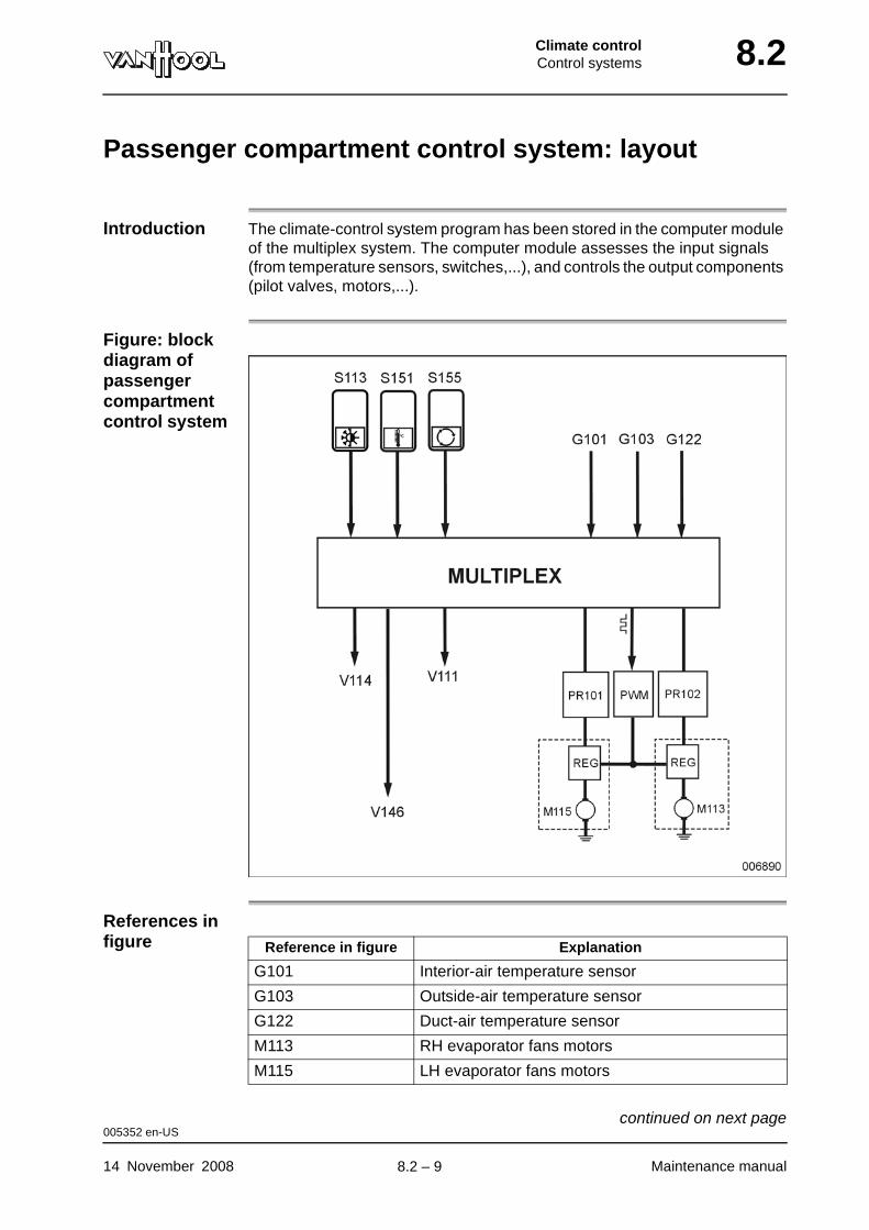
Climate controlControl systems 8.2
Passenger compartment control system: layout
Introduction The climate-control system program has been stored in the computer module of the multiplex system. The computer module assesses the input signals (from temperature sensors, switches,...), and controls the output components (pilot valves, motors,...).
Figure: block diagram of passenger compartment control system
References in figure Reference in figure Explanation
G101 Interior-air temperature sensor
G103 Outside-air temperature sensor
G122 Duct-air temperature sensor
M113 RH evaporator fans motors
M115 LH evaporator fans motors
005352 en-US
14 November 2008 Maintenance manual
continued on next page.
8.2 – 9
8.2 Climate controlControl systems
PR101 Printed circuit with relay and fuses of RH evapo-rator fans
PR102 Printed circuit with relay and fuses of LH evapo-rator fans
PWM "Digital/analog" inverter
REG Electronic speed controller (chopper)
S113 Switch to cut off the system
S151 Temperature setting switch
S155 Switch for 100% inside air
V111 Pilot valve of outside-air flaps
V114 Pilot valve of metering valve in hot-water supply to roof heating
V146 Pilot valve of metering valve in hot-water supply to floor heating
Reference in figure Explanation
005352 en-US
Maintenance manual 14 November 2008
.
8.2 – 10
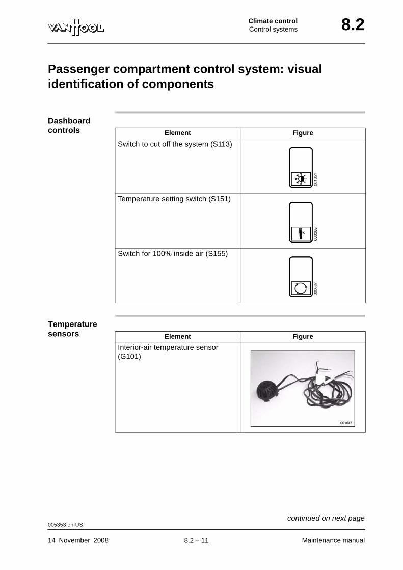
Climate controlControl systems 8.2
Passenger compartment control system: visual identification of components
Dashboard controls
Temperature sensors
Element Figure
Switch to cut off the system (S113)
Temperature setting switch (S151)
Switch for 100% inside air (S155)
Element Figure
Interior-air temperature sensor (G101)
005353 en-US
14 November 2008 Maintenance manual
continued on next page.
8.2 – 11

8.2 Climate controlControl systems
Pilot valves
Duct-air temperature sensor (G122)
Outside-air temperature sensor (G103)
Element Figure
Element Figure
• Pilot valve (V114) of metering valve in hot-water supply to roof heating
• Pilot valve (V146) of metering valve in hot-water supply to floor heating
Pilot valve of outside-air flaps (V111)
005353 en-US
Maintenance manual 14 November 2008
continued on next page.
8.2 – 12
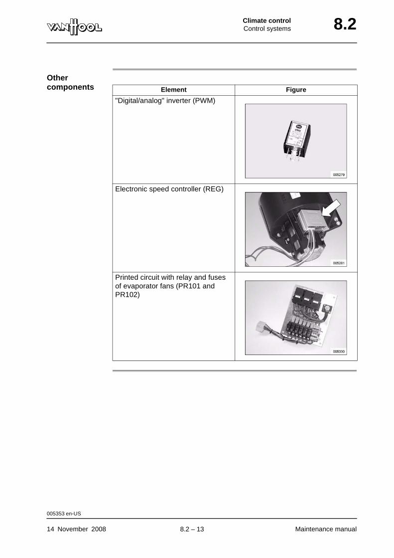
Climate controlControl systems 8.2
Other components Element Figure
"Digital/analog" inverter (PWM)
Electronic speed controller (REG)
Printed circuit with relay and fuses of evaporator fans (PR101 and PR102)
005353 en-US
14 November 2008 Maintenance manual
.
8.2 – 13
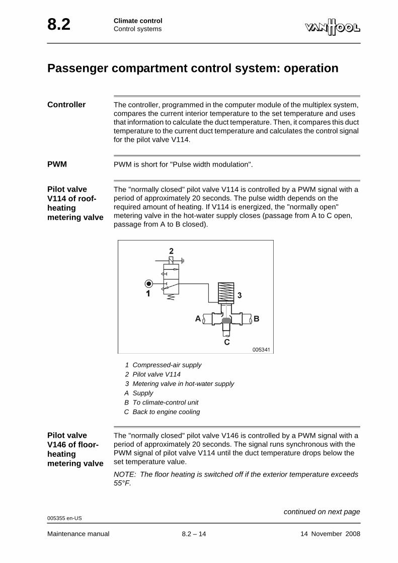
8.2 Climate controlControl systems
Passenger compartment control system: operation
Controller The controller, programmed in the computer module of the multiplex system, compares the current interior temperature to the set temperature and uses that information to calculate the duct temperature. Then, it compares this duct temperature to the current duct temperature and calculates the control signal for the pilot valve V114.
PWM PWM is short for "Pulse width modulation".
Pilot valve V114 of roof-heating metering valve
The "normally closed" pilot valve V114 is controlled by a PWM signal with a period of approximately 20 seconds. The pulse width depends on the required amount of heating. If V114 is energized, the "normally open" metering valve in the hot-water supply closes (passage from A to C open, passage from A to B closed).
1 Compressed-air supply2 Pilot valve V1143 Metering valve in hot-water supplyA SupplyB To climate-control unitC Back to engine cooling
Pilot valve V146 of floor-heating metering valve
The "normally closed" pilot valve V146 is controlled by a PWM signal with a period of approximately 20 seconds. The signal runs synchronous with the PWM signal of pilot valve V114 until the duct temperature drops below the set temperature value.
NOTE: The floor heating is switched off if the exterior temperature exceeds 55°F.
005355 en-US
Maintenance manual 14 November 2008
continued on next page.
8.2 – 14
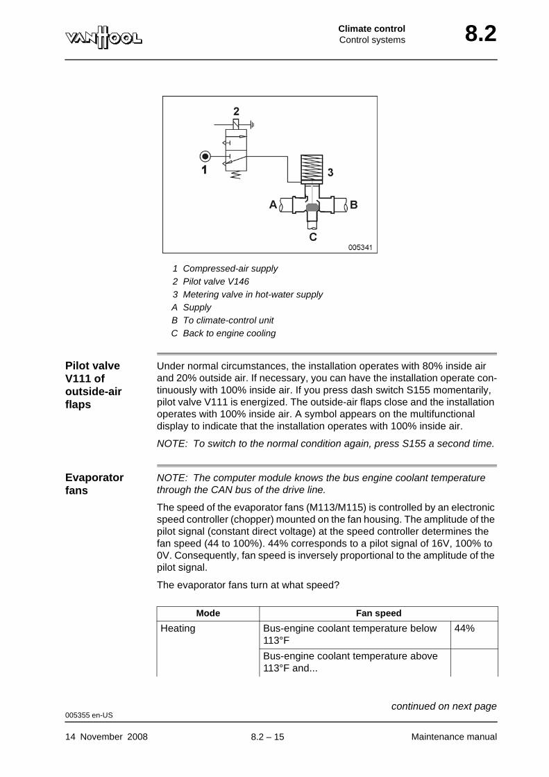
Climate controlControl systems 8.2
1 Compressed-air supply2 Pilot valve V1463 Metering valve in hot-water supplyA SupplyB To climate-control unitC Back to engine cooling
Pilot valve V111 of outside-air flaps
Under normal circumstances, the installation operates with 80% inside air and 20% outside air. If necessary, you can have the installation operate con-tinuously with 100% inside air. If you press dash switch S155 momentarily, pilot valve V111 is energized. The outside-air flaps close and the installation operates with 100% inside air. A symbol appears on the multifunctional display to indicate that the installation operates with 100% inside air.
NOTE: To switch to the normal condition again, press S155 a second time.
Evaporator fans
NOTE: The computer module knows the bus engine coolant temperature through the CAN bus of the drive line.
The speed of the evaporator fans (M113/M115) is controlled by an electronic speed controller (chopper) mounted on the fan housing. The amplitude of the pilot signal (constant direct voltage) at the speed controller determines the fan speed (44 to 100%). 44% corresponds to a pilot signal of 16V, 100% to 0V. Consequently, fan speed is inversely proportional to the amplitude of the pilot signal.
The evaporator fans turn at what speed?
Mode Fan speed
Heating Bus-engine coolant temperature below 113°F
44%
Bus-engine coolant temperature above 113°F and...
005355 en-US
14 November 2008 Maintenance manual
continued on next page.
8.2 – 15

8.2 Climate controlControl systems
"Digital/analog" inverter (PWM)
The "Digital/analog" inverter translates the pilot signal for the electronic speed controller from a PWM signal into a constant direct voltage. The gen-erated PWM signals have a frequency of 50 kHz. This corresponds with a period of 0.2 ms. The amplitude of the direct voltage at the "Digital/analog" inverter output depends on the pulse width of the signal (the wider the pulses, the higher the output voltage)
Climate-control compressor clutch
Refer to "Climate-control compressor: electromagnetic clutch" in chapter 8.14.
Shut-off valves in refrigerant circuit
Refer to "Solenoid shut-off valves" in chapter 8.14.
Refrigerant circuit pressure switches
Refer to "Pressure switches" in chapter 8.14.
• interior temperature more than 7°F lower than the set temperature
66%
• interior temperature less than 7°F lower than the set temperature
44%
"REHEAT", refriger-ation
Stepless between 44 and 100%
V: Fan speed, Ti: interior temperature, Tset: set temper-ature
Mode Fan speed
005355 en-US
Maintenance manual 14 November 2008
continued on next page.
8.2 – 16

Climate controlControl systems 8.2
Condenser fans M21M/M26M
Refer to "Condenser" in chapter 8.14.
Coolant heater (Proheat)
To switch on the coolant heater by means of the dashboard switch or the pro-grammable control, refer to operating manual.
The coolant heater is automatically set in the standby mode when the roof heating metering valve is open for more than 65% of the time. The coolant heater is automatically switched off 5 minutes after the metering valve is open for less than 15% of the time.
Circulating pump M126
The heating-circuit circulating pump runs when the coolant heater is in standby mode.
005355 en-US
14 November 2008 Maintenance manual
continued on next page.
8.2 – 17

8.2 Climate controlControl systems
Switching points with warm engine
Ti Interior temperatureTout Exterior temperatureTset Set temperature
Tk Calculated duct temperatureCom Climate-control compressor
Explanation of switching points with warm engine
Switching point Explanation
1 Interior temperature below control range (maximum heating capacity)
2 Interior temperature 7°F below set temperature
3 Exterior temperature 25°F
4 Calculated duct temperature equal to set temperature
5 Roof-heating metering valve open for more than 40% of the time
005355 en-US
Maintenance manual 14 November 2008
continued on next page.
8.2 – 18
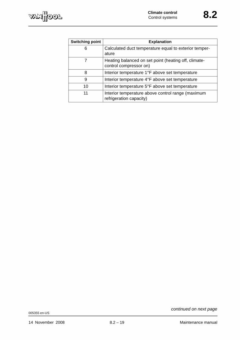
Climate controlControl systems 8.2
6 Calculated duct temperature equal to exterior temper-ature
7 Heating balanced on set point (heating off, climate-control compressor on)
8 Interior temperature 1°F above set temperature
9 Interior temperature 4°F above set temperature
10 Interior temperature 5°F above set temperature
11 Interior temperature above control range (maximum refrigeration capacity)
Switching point Explanation
005355 en-US
14 November 2008 Maintenance manual
continued on next page.
8.2 – 19
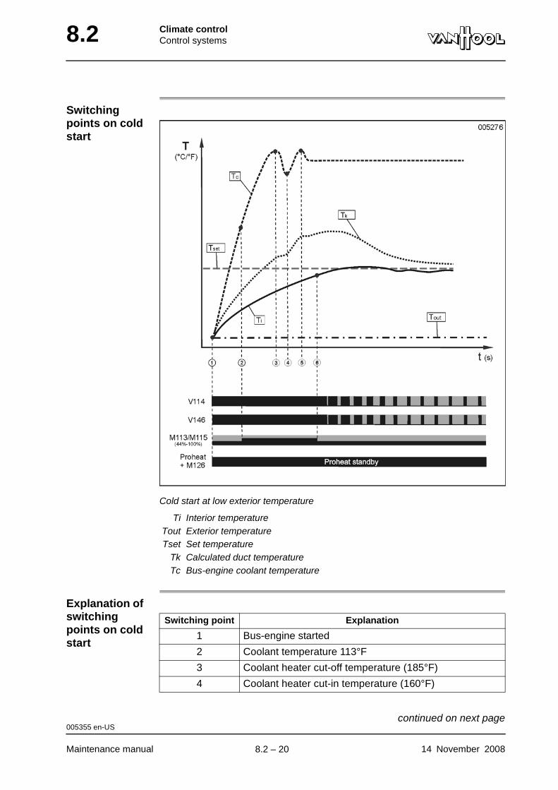
8.2 Climate controlControl systems
Switching points on cold start
Cold start at low exterior temperature
Ti Interior temperatureTout Exterior temperatureTset Set temperature
Tk Calculated duct temperatureTc Bus-engine coolant temperature
Explanation of switching points on cold start
Switching point Explanation
1 Bus-engine started
2 Coolant temperature 113°F
3 Coolant heater cut-off temperature (185°F)
4 Coolant heater cut-in temperature (160°F)
005355 en-US
Maintenance manual 14 November 2008
continued on next page.
8.2 – 20
Climate controlControl systems 8.2
5 Interior temperature 7°F lower than set temperature
Switching point Explanation
005355 en-US
14 November 2008 Maintenance manual
.
8.2 – 21
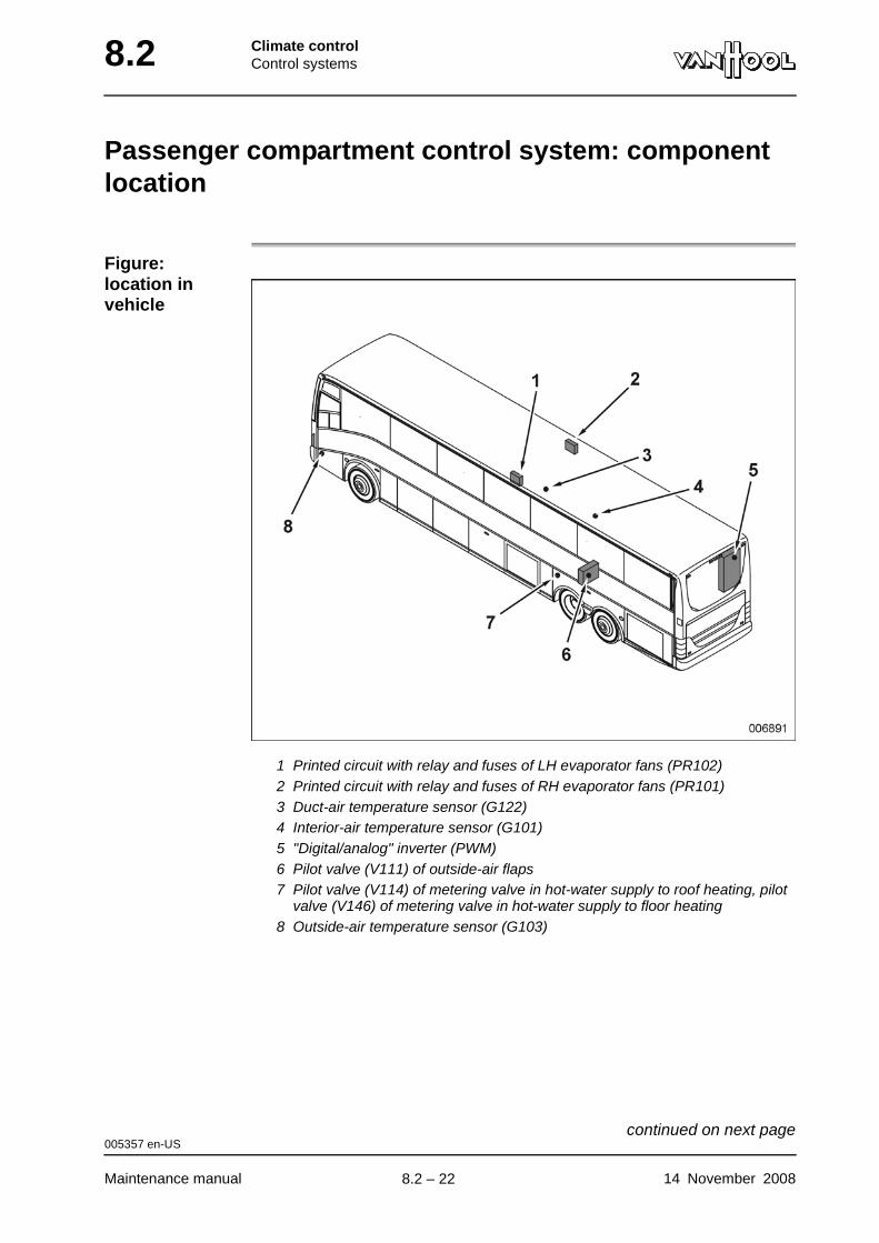
8.2 Climate controlControl systems
Passenger compartment control system: component location
Figure: location in vehicle
1 Printed circuit with relay and fuses of LH evaporator fans (PR102)2 Printed circuit with relay and fuses of RH evaporator fans (PR101)3 Duct-air temperature sensor (G122)4 Interior-air temperature sensor (G101)5 "Digital/analog" inverter (PWM)6 Pilot valve (V111) of outside-air flaps7 Pilot valve (V114) of metering valve in hot-water supply to roof heating, pilot
valve (V146) of metering valve in hot-water supply to floor heating8 Outside-air temperature sensor (G103)
005357 en-US
Maintenance manual 14 November 2008
continued on next page.
8.2 – 22
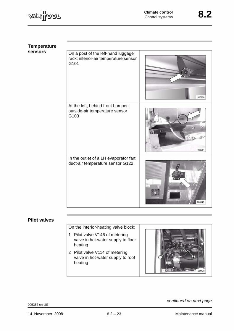
Climate controlControl systems 8.2
Temperature sensors
Pilot valves
On a post of the left-hand luggage rack: interior-air temperature sensor G101
At the left, behind front bumper: outside-air temperature sensor G103
In the outlet of a LH evaporator fan: duct-air temperature sensor G122
On the interior-heating valve block:
1 Pilot valve V146 of metering valve in hot-water supply to floor heating
2 Pilot valve V114 of metering valve in hot-water supply to roof heating
005357 en-US
14 November 2008 Maintenance manual
continued on next page.
8.2 – 23
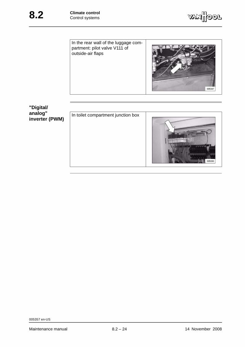
8.2 Climate controlControl systems
"Digital/analog" inverter (PWM)
In the rear wall of the luggage com-partment: pilot valve V111 of outside-air flaps
In toilet compartment junction box
005357 en-US
Maintenance manual 14 November 2008
.
8.2 – 24

Climate controlControl systems 8.2
Passenger compartment control system: to troubleshoot using the multifunctional display
Introduction To simplify the troubleshooting process, the multiplex system of the vehicle has been provided with a climate control test program.
Equipment condition
Battery isolating switch on
To operate the multifunc-tional display
For more information on how to scroll through menus and to select functions in the service menu of the multifunctional display, see chapter 11.1, under "To operate the multifunctional display".
"Running engine" simulation
Some components of the climate control system can only operate if the engine is running. A "running engine" simulation program allows you to activate these components without the engine actually running. To activate this program, see under "Passenger compartment control system: to activate the "running engine" simulation" in the present chapter.
NOTE: It is not recommended to use the climate control system fans during the "running engine" simulation, unless there good reasons for doing so. This will avoid putting a load on the batteries and draining them.
To check equipment operation
You can use the test program to activate equipment yourself to determine how it responds to control signals.
NOTE: If you use the "running engine" simulation to activate the electromag-netic clutch of the climate-control compressor, do so only for a short time while an assistant checks that the clutch responds. If it remains activated for too long, the electromagnet will overheat.
002849 en-US
14 November 2008 Maintenance manual
continued on next page.
8.2 – 25
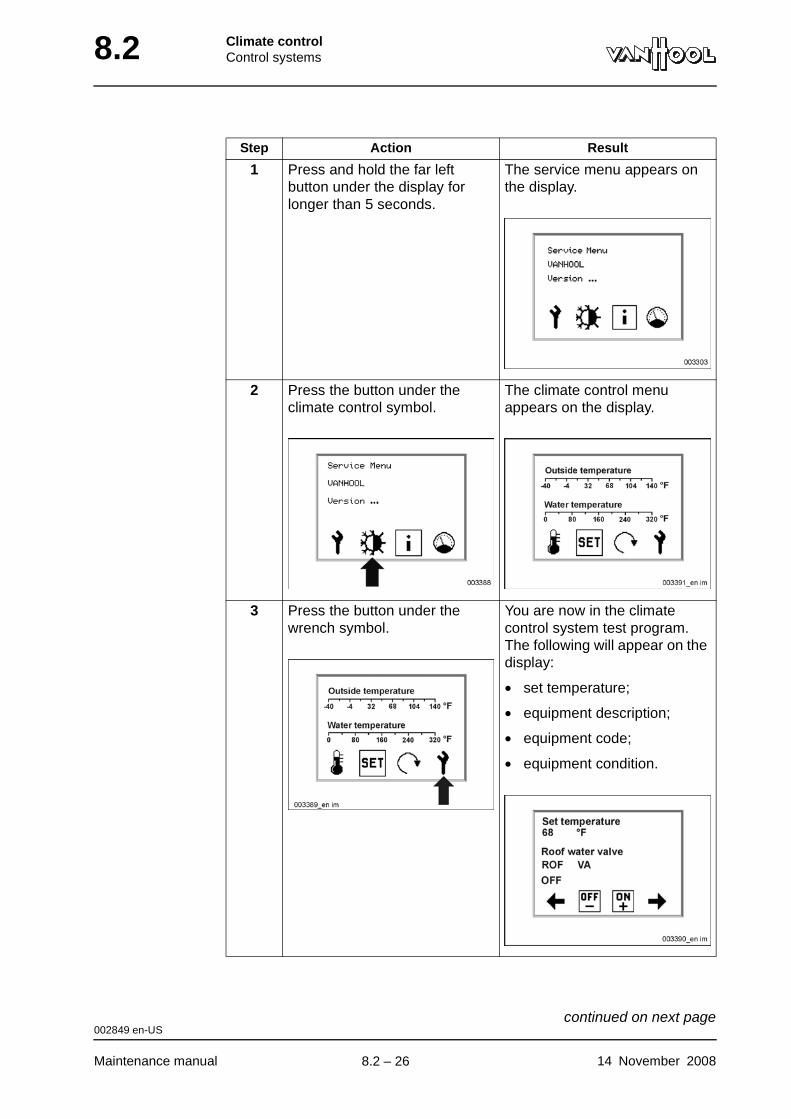
8.2 Climate controlControl systems
Step Action Result
1 Press and hold the far left button under the display for longer than 5 seconds.
The service menu appears on the display.
2 Press the button under the climate control symbol.
The climate control menu appears on the display.
3 Press the button under the wrench symbol.
You are now in the climate control system test program. The following will appear on the display:
• set temperature;
• equipment description;
• equipment code;
• equipment condition.
002849 en-US
Maintenance manual 14 November 2008
continued on next page.
8.2 – 26
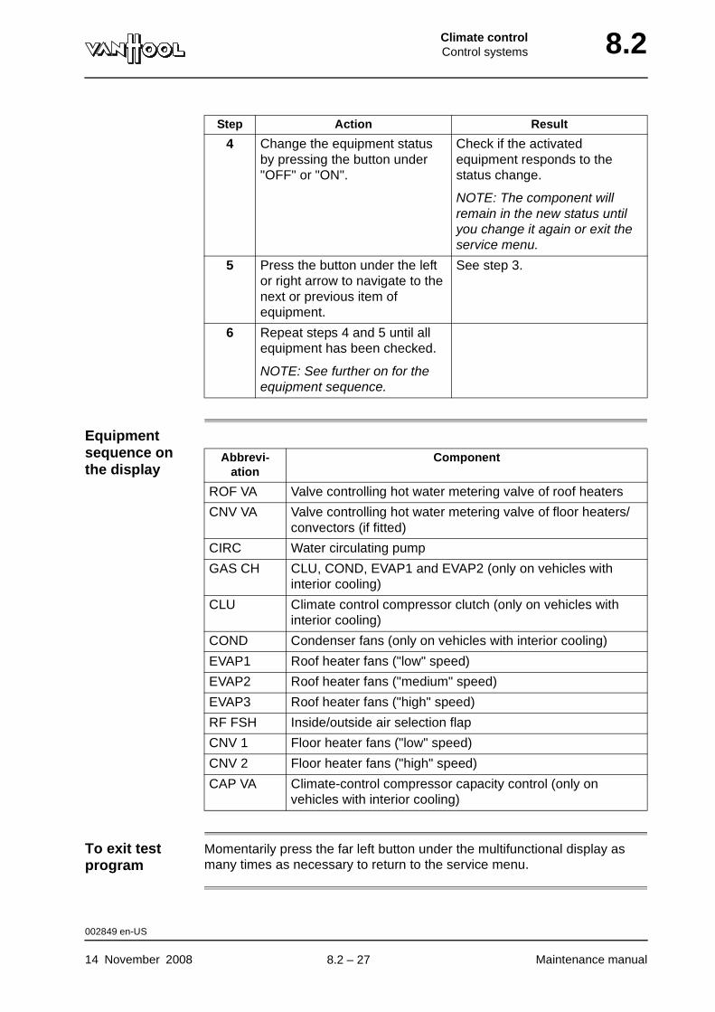
Climate controlControl systems 8.2
Equipment sequence on the display
To exit test program
Momentarily press the far left button under the multifunctional display as many times as necessary to return to the service menu.
4 Change the equipment status by pressing the button under "OFF" or "ON".
Check if the activated equipment responds to the status change.
NOTE: The component will remain in the new status until you change it again or exit the service menu.
5 Press the button under the left or right arrow to navigate to the next or previous item of equipment.
See step 3.
6 Repeat steps 4 and 5 until all equipment has been checked.
NOTE: See further on for the equipment sequence.
Step Action Result
Abbrevi-ation
Component
ROF VA Valve controlling hot water metering valve of roof heaters
CNV VA Valve controlling hot water metering valve of floor heaters/convectors (if fitted)
CIRC Water circulating pump
GAS CH CLU, COND, EVAP1 and EVAP2 (only on vehicles with interior cooling)
CLU Climate control compressor clutch (only on vehicles with interior cooling)
COND Condenser fans (only on vehicles with interior cooling)
EVAP1 Roof heater fans ("low" speed)
EVAP2 Roof heater fans ("medium" speed)
EVAP3 Roof heater fans ("high" speed)
RF FSH Inside/outside air selection flap
CNV 1 Floor heater fans ("low" speed)
CNV 2 Floor heater fans ("high" speed)
CAP VA Climate-control compressor capacity control (only on vehicles with interior cooling)
002849 en-US
14 November 2008 Maintenance manual
.
8.2 – 27
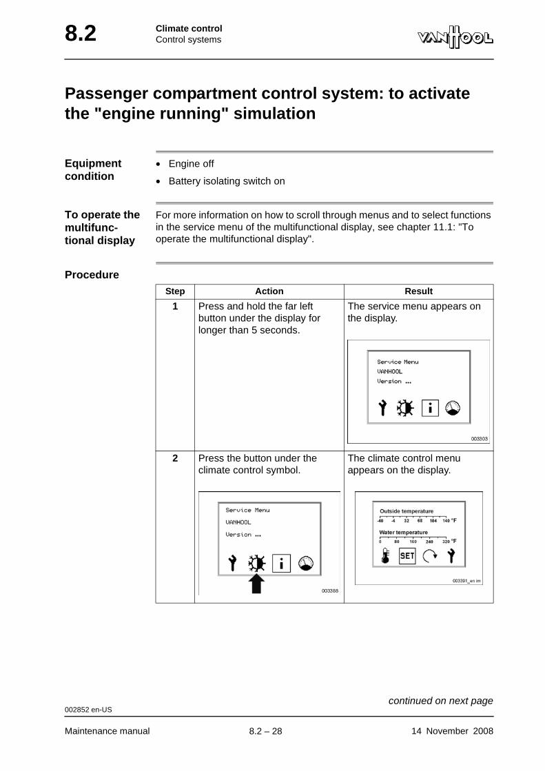
8.2 Climate controlControl systems
Passenger compartment control system: to activate the "engine running" simulation
Equipment condition
• Engine off
• Battery isolating switch on
To operate the multifunc-tional display
For more information on how to scroll through menus and to select functions in the service menu of the multifunctional display, see chapter 11.1: "To operate the multifunctional display".
ProcedureStep Action Result
1 Press and hold the far left button under the display for longer than 5 seconds.
The service menu appears on the display.
2 Press the button under the climate control symbol.
The climate control menu appears on the display.
002852 en-US
Maintenance manual 14 November 2008
continued on next page.
8.2 – 28
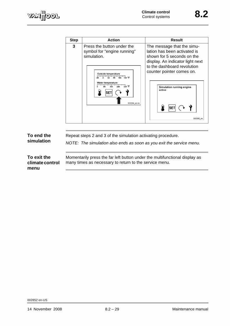
Climate controlControl systems 8.2
To end the simulation
Repeat steps 2 and 3 of the simulation activating procedure.
NOTE: The simulation also ends as soon as you exit the service menu.
To exit the climate control menu
Momentarily press the far left button under the multifunctional display as many times as necessary to return to the service menu.
3 Press the button under the symbol for "engine running" simulation.
The message that the simu-lation has been activated is shown for 5 seconds on the display. An indicator light next to the dashboard revolution counter pointer comes on.
Step Action Result
002852 en-US
14 November 2008 Maintenance manual
.
8.2 – 29
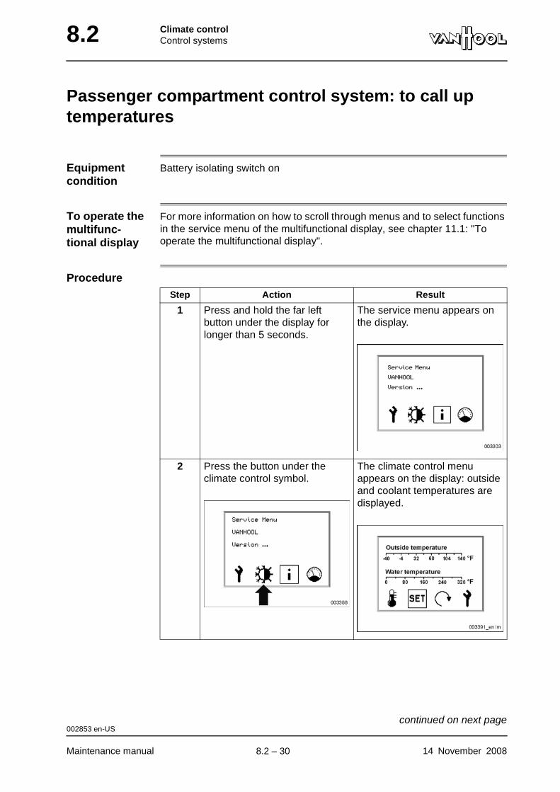
8.2 Climate controlControl systems
Passenger compartment control system: to call up temperatures
Equipment condition
Battery isolating switch on
To operate the multifunc-tional display
For more information on how to scroll through menus and to select functions in the service menu of the multifunctional display, see chapter 11.1: "To operate the multifunctional display".
ProcedureStep Action Result
1 Press and hold the far left button under the display for longer than 5 seconds.
The service menu appears on the display.
2 Press the button under the climate control symbol.
The climate control menu appears on the display: outside and coolant temperatures are displayed.
002853 en-US
Maintenance manual 14 November 2008
continued on next page.
8.2 – 30
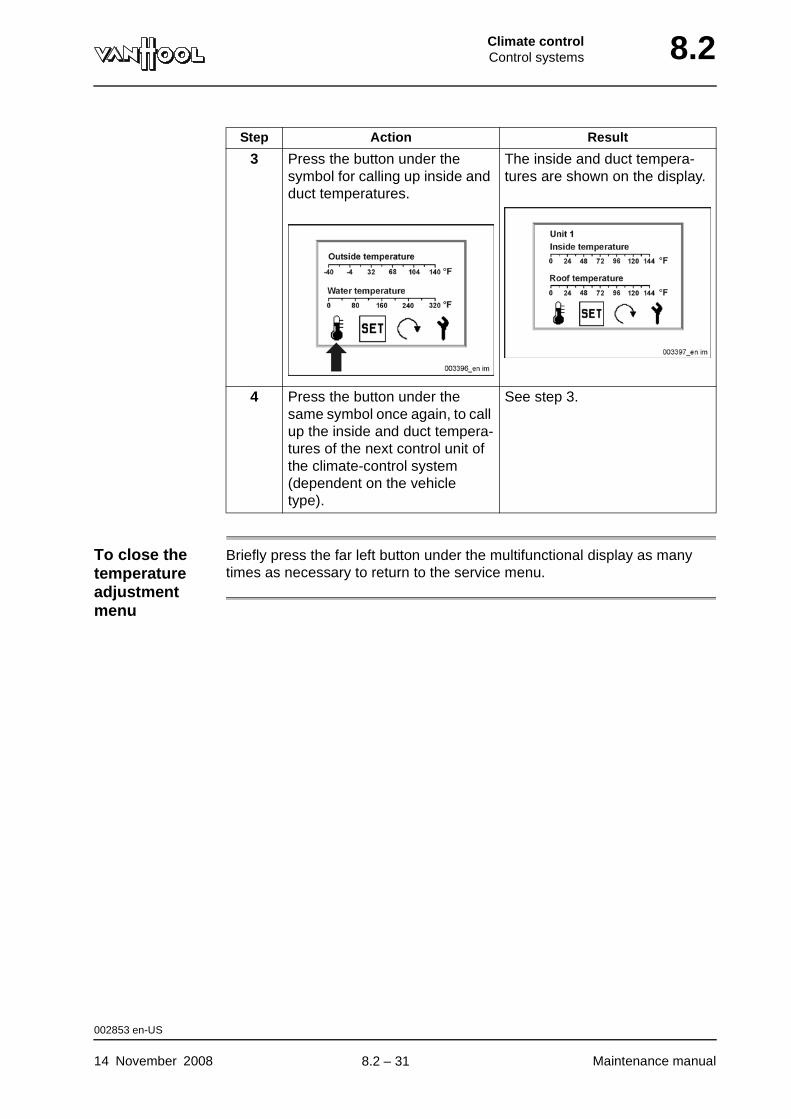
Climate controlControl systems 8.2
To close the temperature adjustment menu
Briefly press the far left button under the multifunctional display as many times as necessary to return to the service menu.
3 Press the button under the symbol for calling up inside and duct temperatures.
The inside and duct tempera-tures are shown on the display.
4 Press the button under the same symbol once again, to call up the inside and duct tempera-tures of the next control unit of the climate-control system (dependent on the vehicle type).
See step 3.
Step Action Result
002853 en-US
14 November 2008 Maintenance manual
.
8.2 – 31
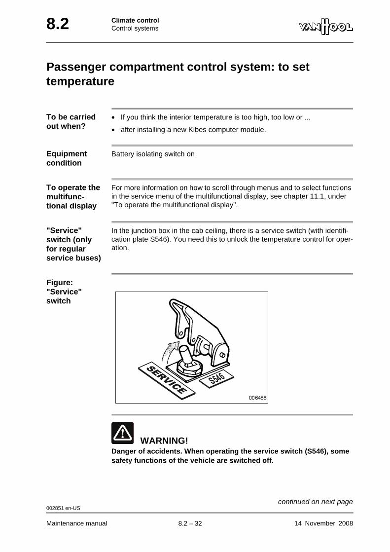
8.2 Climate controlControl systems
Passenger compartment control system: to set temperature
To be carried out when?
• If you think the interior temperature is too high, too low or ...
• after installing a new Kibes computer module.
Equipment condition
Battery isolating switch on
To operate the multifunc-tional display
For more information on how to scroll through menus and to select functions in the service menu of the multifunctional display, see chapter 11.1, under "To operate the multifunctional display".
"Service" switch (only for regular service buses)
In the junction box in the cab ceiling, there is a service switch (with identifi-cation plate S546). You need this to unlock the temperature control for oper-ation.
Figure: "Service" switch
WARNING!Danger of accidents. When operating the service switch (S546), some safety functions of the vehicle are switched off.
002851 en-US
Maintenance manual 14 November 2008
continued on next page.
8.2 – 32
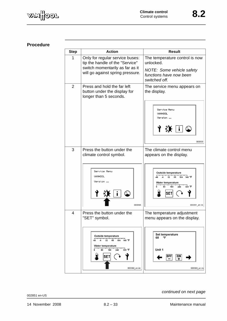
Climate controlControl systems 8.2
ProcedureStep Action Result
1 Only for regular service buses: tip the handle of the "Service" switch momentarily as far as it will go against spring pressure.
The temperature control is now unlocked.
NOTE: Some vehicle safety functions have now been switched off.
2 Press and hold the far left button under the display for longer than 5 seconds.
The service menu appears on the display.
3 Press the button under the climate control symbol.
The climate control menu appears on the display.
4 Press the button under the "SET" symbol.
The temperature adjustment menu appears on the display.
002851 en-US
14 November 2008 Maintenance manual
continued on next page.
8.2 – 33
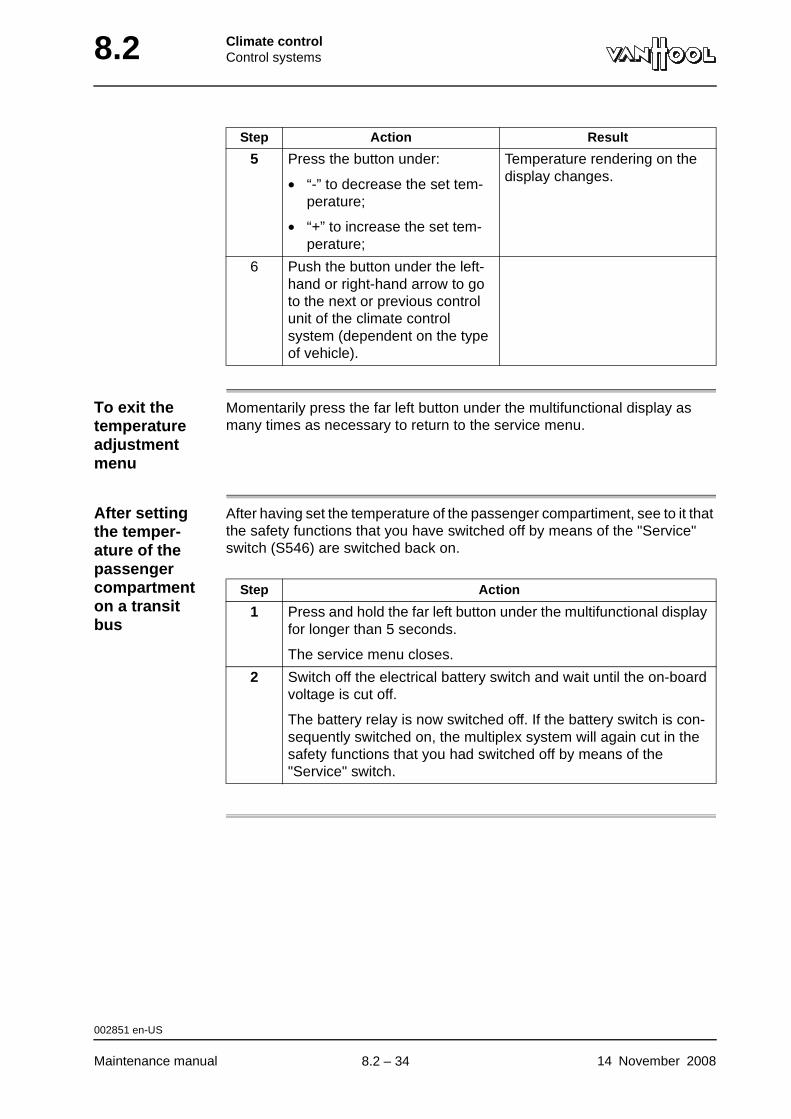
8.2 Climate controlControl systems
To exit the temperature adjustment menu
Momentarily press the far left button under the multifunctional display as many times as necessary to return to the service menu.
After setting the temper-ature of the passenger compartment on a transit bus
After having set the temperature of the passenger compartiment, see to it that the safety functions that you have switched off by means of the "Service" switch (S546) are switched back on.
5 Press the button under:
• “-” to decrease the set tem-perature;
• “+” to increase the set tem-perature;
Temperature rendering on the display changes.
6 Push the button under the left-hand or right-hand arrow to go to the next or previous control unit of the climate control system (dependent on the type of vehicle).
Step Action Result
Step Action
1 Press and hold the far left button under the multifunctional display for longer than 5 seconds.
The service menu closes.
2 Switch off the electrical battery switch and wait until the on-board voltage is cut off.
The battery relay is now switched off. If the battery switch is con-sequently switched on, the multiplex system will again cut in the safety functions that you had switched off by means of the "Service" switch.
002851 en-US
Maintenance manual 14 November 2008
.
8.2 – 34
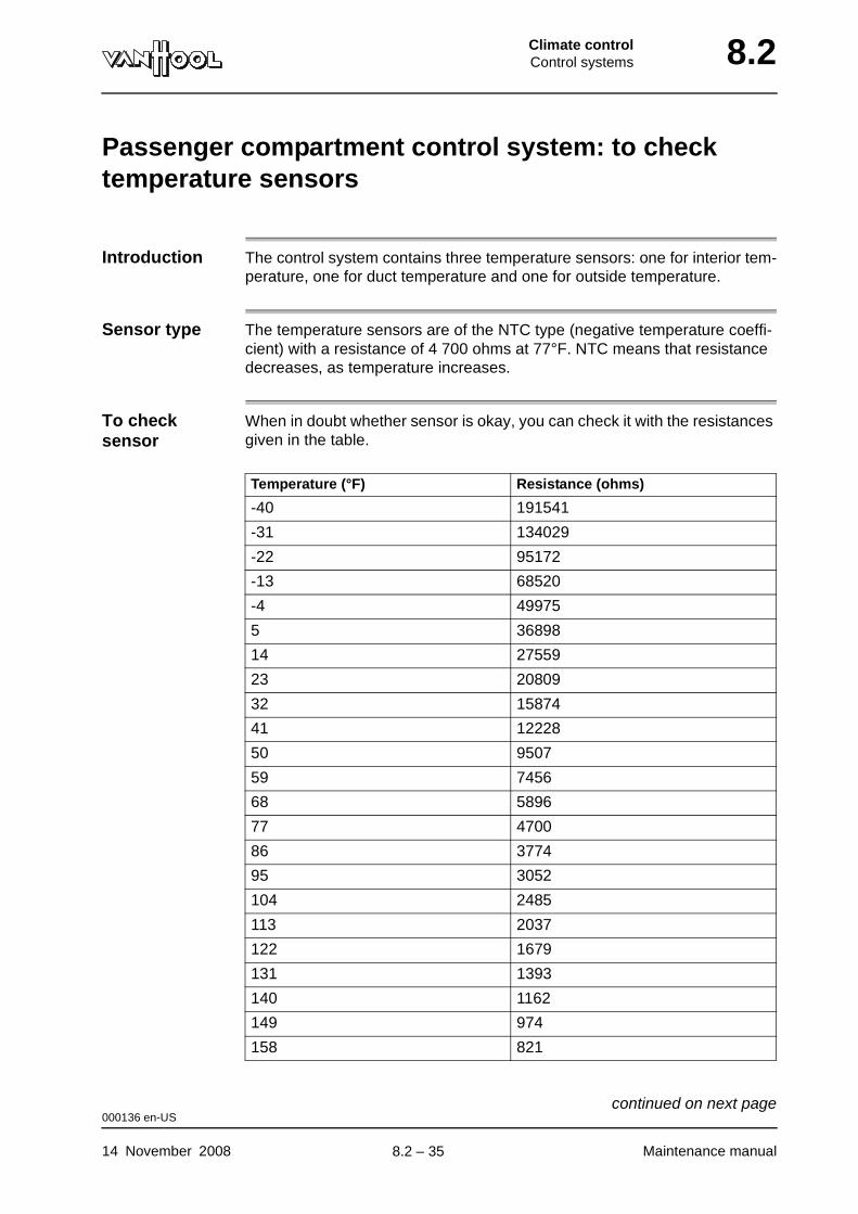
Climate controlControl systems 8.2
Passenger compartment control system: to check temperature sensors
Introduction The control system contains three temperature sensors: one for interior tem-perature, one for duct temperature and one for outside temperature.
Sensor type The temperature sensors are of the NTC type (negative temperature coeffi-cient) with a resistance of 4 700 ohms at 77°F. NTC means that resistance decreases, as temperature increases.
To check sensor
When in doubt whether sensor is okay, you can check it with the resistances given in the table.
Temperature (°F) Resistance (ohms)
-40 191541
-31 134029
-22 95172
-13 68520
-4 49975
5 36898
14 27559
23 20809
32 15874
41 12228
50 9507
59 7456
68 5896
77 4700
86 3774
95 3052
104 2485
113 2037
122 1679
131 1393
140 1162
149 974
158 821
000136 en-US
14 November 2008 Maintenance manual
continued on next page.
8.2 – 35
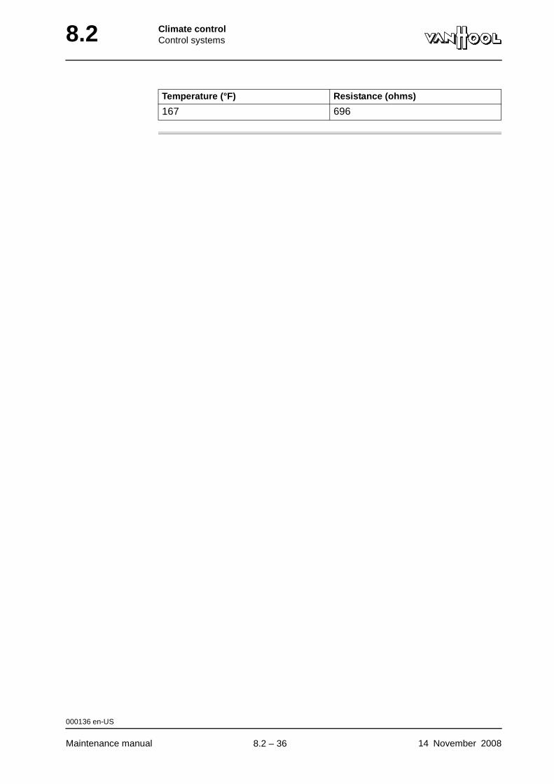
8.2 Climate controlControl systems
167 696
Temperature (°F) Resistance (ohms)
000136 en-US
Maintenance manual 14 November 2008
.
8.2 – 36
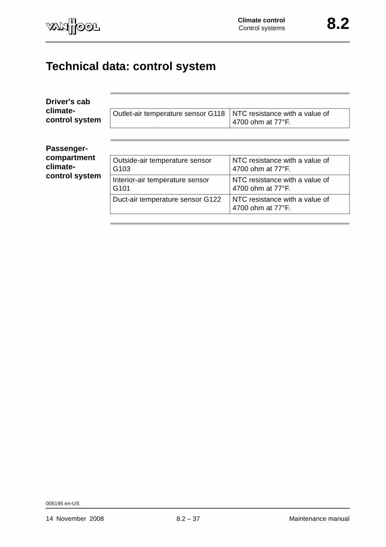
Climate controlControl systems 8.2
Technical data: control system
Driver's cab climate-control system
Passenger-compartment climate-control system
Outlet-air temperature sensor G118 NTC resistance with a value of 4700 ohm at 77°F.
Outside-air temperature sensor G103
NTC resistance with a value of 4700 ohm at 77°F.
Interior-air temperature sensor G101
NTC resistance with a value of 4700 ohm at 77°F.
Duct-air temperature sensor G122 NTC resistance with a value of 4700 ohm at 77°F.
005195 en-US
14 November 2008 Maintenance manual
.
8.2 – 37

8.2 Climate controlControl systems
This page has been intentionally left blank.
005195 en-US
Maintenance manual 14 November 20088.2 – 38
Climate controlAirside systems 8.6
Chapter 6: Airside systems
Overview
Introduction This chapter deals with the airside systems.
Number of pages
6
Chapter publi-cation date
2 January 2008
Contents
Topic See page
To check/clean filter cloth of climate-control units 8.6-2
To remove filter cloth of driver's compartment climate-control unit
8.6-4
To remove filter cloth of passenger compartment climate-control units
8.6-5
2 January 2008 Maintenance manual
.
8.6 – 1
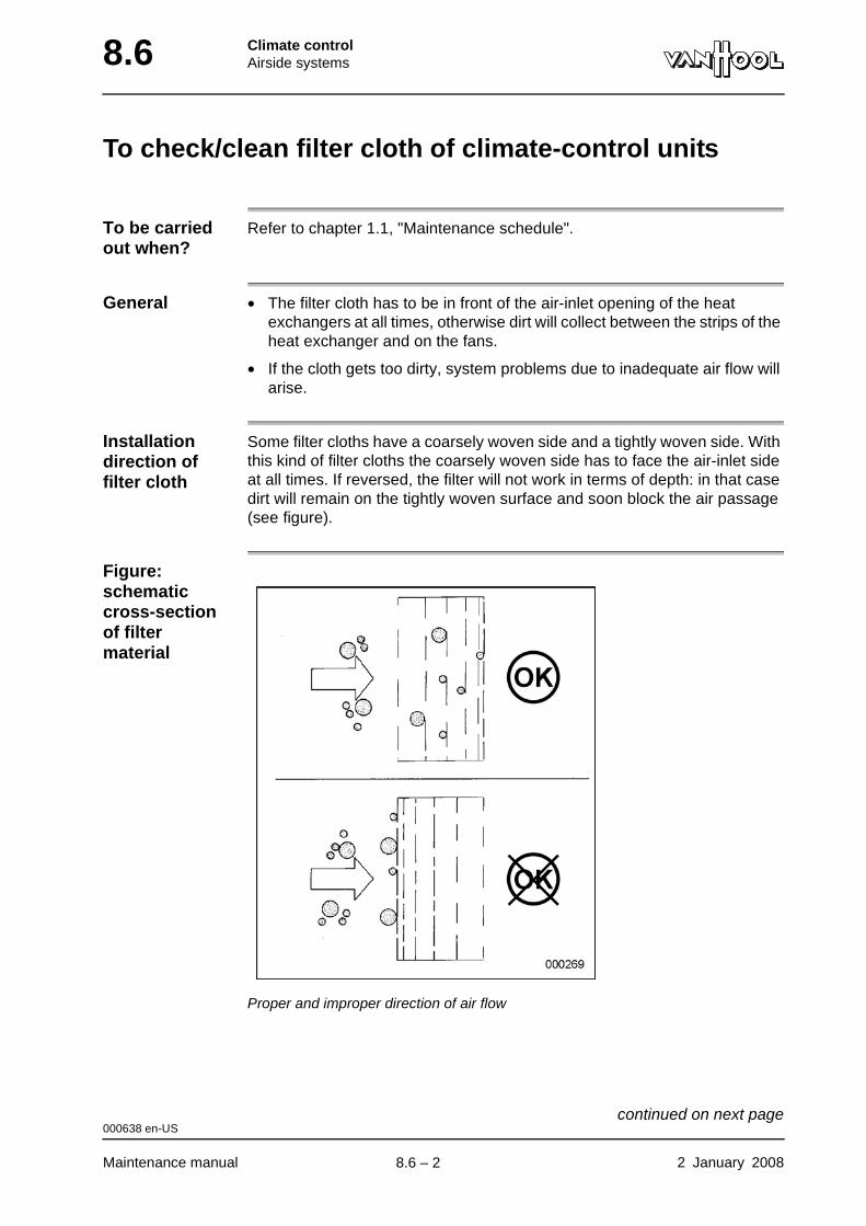
8.6 Climate controlAirside systems
To check/clean filter cloth of climate-control units
To be carried out when?
Refer to chapter 1.1, "Maintenance schedule".
General • The filter cloth has to be in front of the air-inlet opening of the heat exchangers at all times, otherwise dirt will collect between the strips of the heat exchanger and on the fans.
• If the cloth gets too dirty, system problems due to inadequate air flow will arise.
Installation direction of filter cloth
Some filter cloths have a coarsely woven side and a tightly woven side. With this kind of filter cloths the coarsely woven side has to face the air-inlet side at all times. If reversed, the filter will not work in terms of depth: in that case dirt will remain on the tightly woven surface and soon block the air passage (see figure).
Figure: schematic cross-section of filter material
Proper and improper direction of air flow
000638 en-US
Maintenance manual 2 January 2008
continued on next page.
8.6 – 2
Climate controlAirside systems 8.6
To clean filter cloth
To install filter cloth
Re-install cloth (procedure for removing filter cloth in reverse order).
Take care that new or cleaned filter cloth covers entire air flow opening. Never install a cloth that is too small or damaged.
Step Action
1 Remove filter cloth from climate-control unit.
2 Shake out cloth.
3 Wash cloth in lukewarm water.
If heavily soiled, add mild detergent to water.
4 Rinse cloth thoroughly.
5 Allow cloth to dry completely before using. Do not wring it out; do not blow dry with compressed air.
000638 en-US
2 January 2008 Maintenance manual
.
8.6 – 3
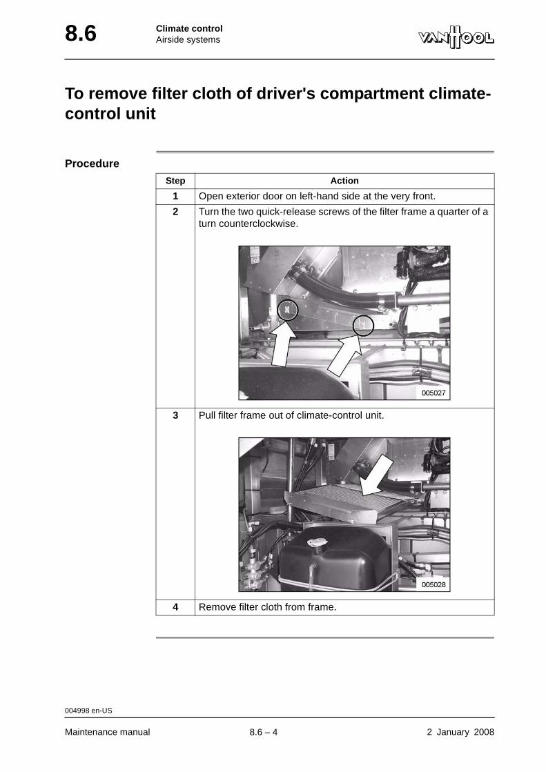
8.6 Climate controlAirside systems
To remove filter cloth of driver's compartment climate-control unit
Procedure
Step Action
1 Open exterior door on left-hand side at the very front.
2 Turn the two quick-release screws of the filter frame a quarter of a turn counterclockwise.
3 Pull filter frame out of climate-control unit.
4 Remove filter cloth from frame.
004998 en-US
Maintenance manual 2 January 2008
.
8.6 – 4
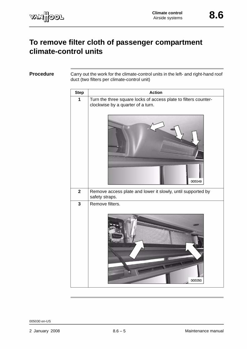
Climate controlAirside systems 8.6
To remove filter cloth of passenger compartment climate-control units
Procedure Carry out the work for the climate-control units in the left- and right-hand roof duct (two filters per climate-control unit)
Step Action
1 Turn the three square locks of access plate to filters counter-clockwise by a quarter of a turn.
2 Remove access plate and lower it slowly, until supported by safety straps.
3 Remove filters.
005030 en-US
2 January 2008 Maintenance manual
.
8.6 – 5
8.6 Climate controlAirside systems
This page has been intentionally left blank.
005030 en-US
Maintenance manual 2 January 20088.6 – 6

Climate controlWater circuit 8.10
Chapter 10: Water circuit
Overview
Introduction This chapter deals with the water circuit.
Number of pages
14
Chapter publi-cation date
14 November 2008
Contents
Topic See page
Safety instructions with respect to the water circuit 8.10-2
Protection against frost, deposits and corrosion 8.10-4
To drain engine cooling and interior heating circuit 8.10-5
To fill and bleed engine cooling and interior heating circuit 8.10-7
Interior heating circuit isolating valves 8.10-10
To check water circulating pump for leaks 8.10-11
To check condition of water hoses 8.10-12
Hose clamp types 8.10-13
To check hose clamps tightening torque 8.10-14
14 November 2008 Maintenance manual
.
8.10 – 1
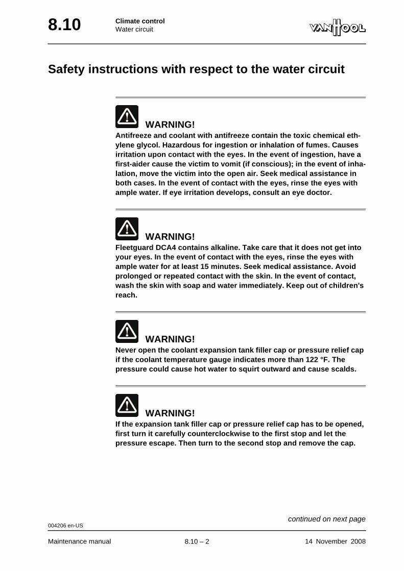
8.10 Climate controlWater circuit
Safety instructions with respect to the water circuit
WARNING!Antifreeze and coolant with antifreeze contain the toxic chemical eth-ylene glycol. Hazardous for ingestion or inhalation of fumes. Causes irritation upon contact with the eyes. In the event of ingestion, have a first-aider cause the victim to vomit (if conscious); in the event of inha-lation, move the victim into the open air. Seek medical assistance in both cases. In the event of contact with the eyes, rinse the eyes with ample water. If eye irritation develops, consult an eye doctor.
WARNING!Fleetguard DCA4 contains alkaline. Take care that it does not get into your eyes. In the event of contact with the eyes, rinse the eyes with ample water for at least 15 minutes. Seek medical assistance. Avoid prolonged or repeated contact with the skin. In the event of contact, wash the skin with soap and water immediately. Keep out of children's reach.
WARNING!Never open the coolant expansion tank filler cap or pressure relief cap if the coolant temperature gauge indicates more than 122 °F. The pressure could cause hot water to squirt outward and cause scalds.
WARNING!If the expansion tank filler cap or pressure relief cap has to be opened, first turn it carefully counterclockwise to the first stop and let the pressure escape. Then turn to the second stop and remove the cap.
004206 en-US
Maintenance manual 14 November 2008
continued on next page.
8.10 – 2
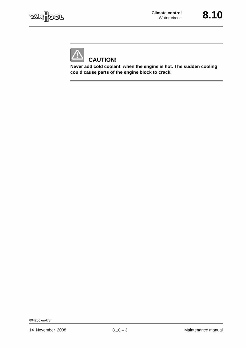
Climate controlWater circuit 8.10
CAUTION!Never add cold coolant, when the engine is hot. The sudden cooling could cause parts of the engine block to crack.
004206 en-US
14 November 2008 Maintenance manual
.
8.10 – 3

8.10 Climate controlWater circuit
Protection against frost, deposits and corrosion
Cross-reference
Refer to chapter 2.34, “Cooling system”.
000672 en-US
Maintenance manual 14 November 2008
.
8.10 – 4
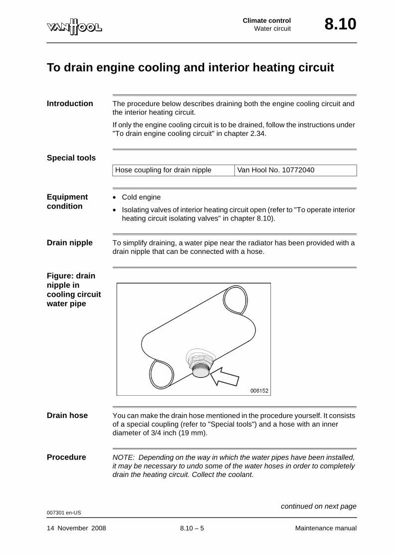
Climate controlWater circuit 8.10
To drain engine cooling and interior heating circuit
Introduction The procedure below describes draining both the engine cooling circuit and the interior heating circuit.
If only the engine cooling circuit is to be drained, follow the instructions under "To drain engine cooling circuit" in chapter 2.34.
Special tools
Equipment condition
• Cold engine
• Isolating valves of interior heating circuit open (refer to "To operate interior heating circuit isolating valves" in chapter 8.10).
Drain nipple To simplify draining, a water pipe near the radiator has been provided with a drain nipple that can be connected with a hose.
Figure: drain nipple in cooling circuit water pipe
Drain hose You can make the drain hose mentioned in the procedure yourself. It consists of a special coupling (refer to "Special tools") and a hose with an inner diameter of 3/4 inch (19 mm).
Procedure NOTE: Depending on the way in which the water pipes have been installed, it may be necessary to undo some of the water hoses in order to completely drain the heating circuit. Collect the coolant.
Hose coupling for drain nipple Van Hool No. 10772040
007301 en-US
14 November 2008 Maintenance manual
continued on next page.
8.10 – 5
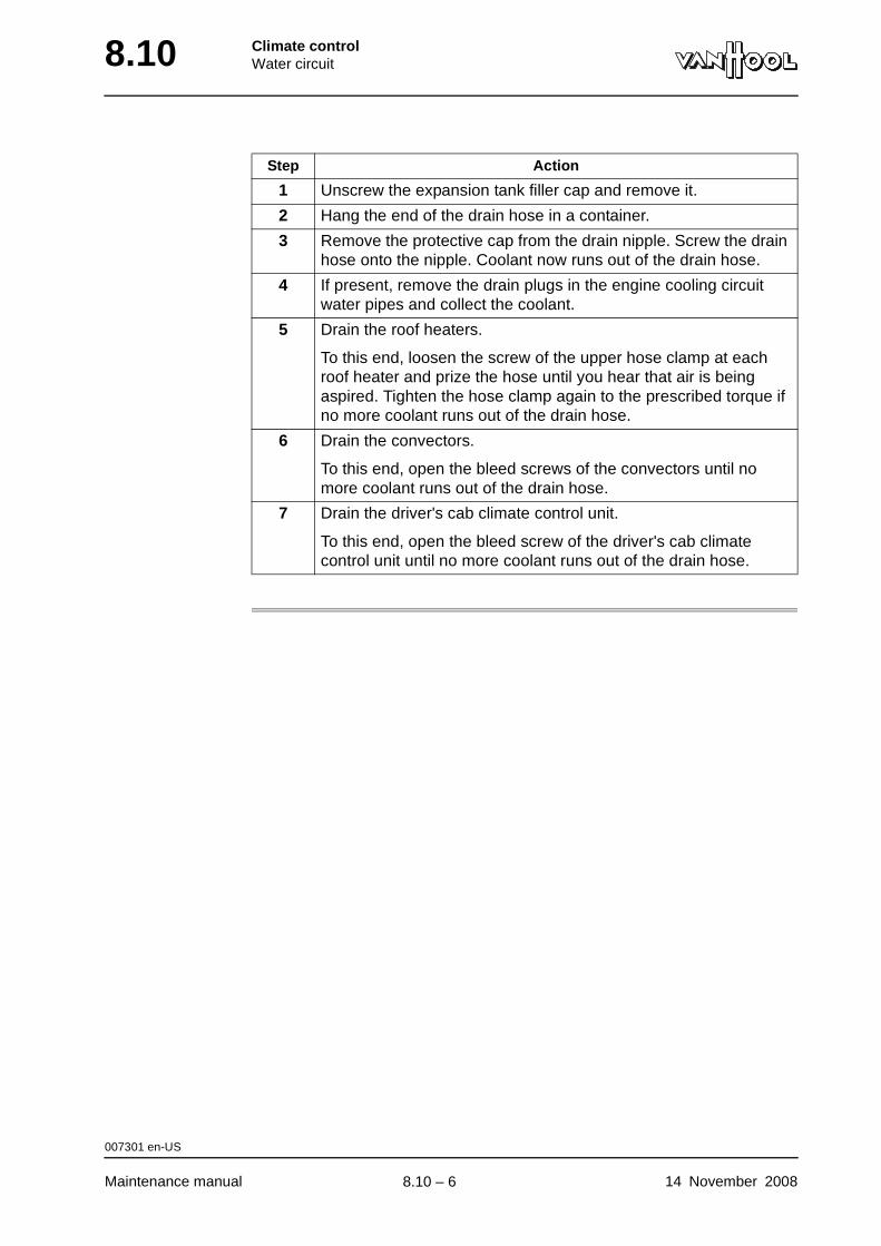
8.10 Climate controlWater circuit
Step Action
1 Unscrew the expansion tank filler cap and remove it.
2 Hang the end of the drain hose in a container.
3 Remove the protective cap from the drain nipple. Screw the drain hose onto the nipple. Coolant now runs out of the drain hose.
4 If present, remove the drain plugs in the engine cooling circuit water pipes and collect the coolant.
5 Drain the roof heaters.
To this end, loosen the screw of the upper hose clamp at each roof heater and prize the hose until you hear that air is being aspired. Tighten the hose clamp again to the prescribed torque if no more coolant runs out of the drain hose.
6 Drain the convectors.
To this end, open the bleed screws of the convectors until no more coolant runs out of the drain hose.
7 Drain the driver's cab climate control unit.
To this end, open the bleed screw of the driver's cab climate control unit until no more coolant runs out of the drain hose.
007301 en-US
Maintenance manual 14 November 2008
.
8.10 – 6
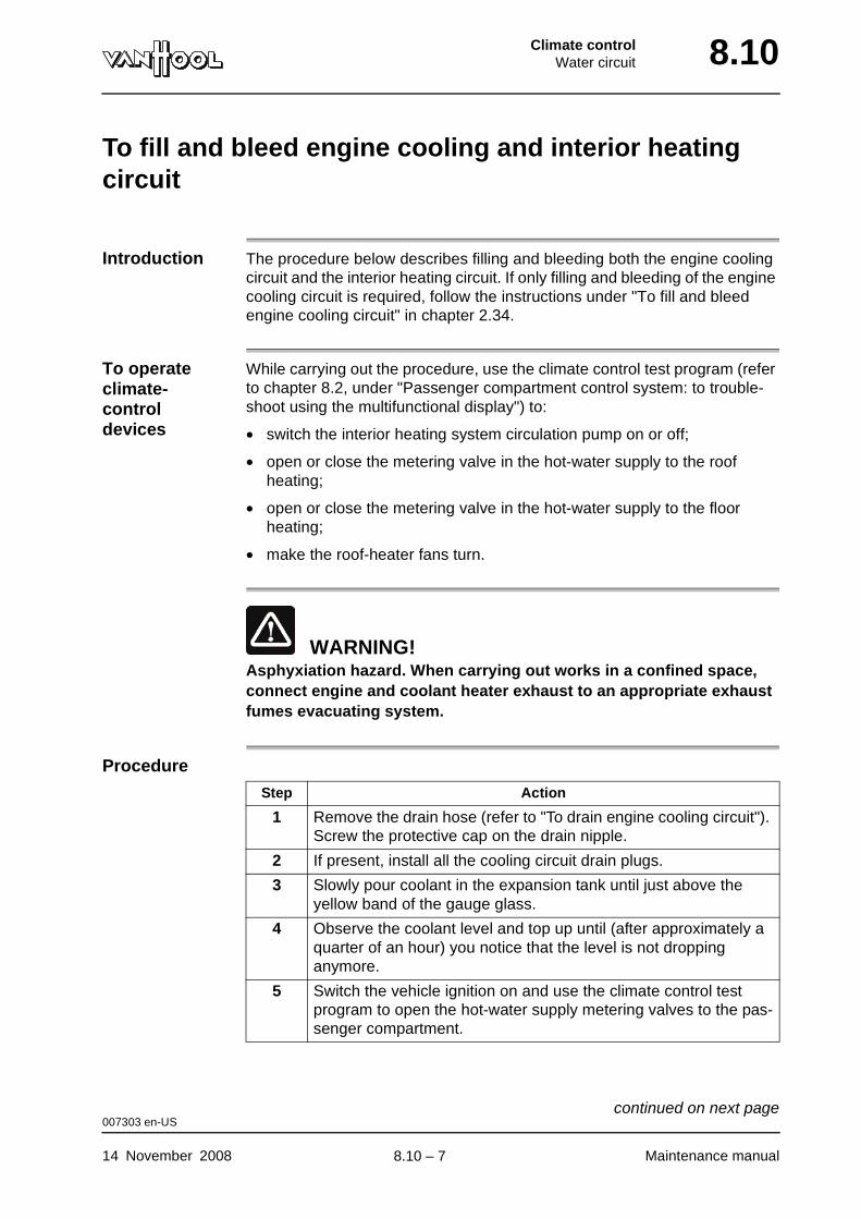
Climate controlWater circuit 8.10
To fill and bleed engine cooling and interior heating circuit
Introduction The procedure below describes filling and bleeding both the engine cooling circuit and the interior heating circuit. If only filling and bleeding of the engine cooling circuit is required, follow the instructions under "To fill and bleed engine cooling circuit" in chapter 2.34.
To operate climate-control devices
While carrying out the procedure, use the climate control test program (refer to chapter 8.2, under "Passenger compartment control system: to trouble-shoot using the multifunctional display") to:
• switch the interior heating system circulation pump on or off;
• open or close the metering valve in the hot-water supply to the roof heating;
• open or close the metering valve in the hot-water supply to the floor heating;
• make the roof-heater fans turn.
WARNING!Asphyxiation hazard. When carrying out works in a confined space, connect engine and coolant heater exhaust to an appropriate exhaust fumes evacuating system.
Procedure
Step Action
1 Remove the drain hose (refer to "To drain engine cooling circuit"). Screw the protective cap on the drain nipple.
2 If present, install all the cooling circuit drain plugs.
3 Slowly pour coolant in the expansion tank until just above the yellow band of the gauge glass.
4 Observe the coolant level and top up until (after approximately a quarter of an hour) you notice that the level is not dropping anymore.
5 Switch the vehicle ignition on and use the climate control test program to open the hot-water supply metering valves to the pas-senger compartment.
007303 en-US
14 November 2008 Maintenance manual
continued on next page.
8.10 – 7
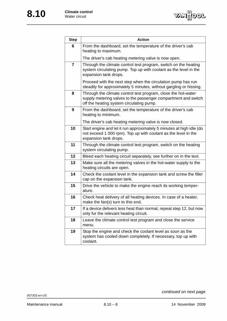
8.10 Climate controlWater circuit
6 From the dashboard, set the temperature of the driver's cab heating to maximum.
The driver's cab heating metering valve is now open.
7 Through the climate control test program, switch on the heating system circulating pump. Top up with coolant as the level in the expansion tank drops.
Proceed with the next step when the circulation pump has run steadily for approximately 5 minutes, without gargling or hissing.
8 Through the climate control test program, close the hot-water supply metering valves to the passenger compartment and switch off the heating system circulating pump.
9 From the dashboard, set the temperature of the driver's cab heating to minimum.
The driver's cab heating metering valve is now closed.
10 Start engine and let it run approximately 5 minutes at high idle (do not exceed 1 000 rpm). Top up with coolant as the level in the expansion tank drops.
11 Through the climate control test program, switch on the heating system circulating pump.
12 Bleed each heating circuit separately, see further on in the text.
13 Make sure all the metering valves in the hot-water supply to the heating circuits are open.
14 Check the coolant level in the expansion tank and screw the filler cap on the expansion tank.
15 Drive the vehicle to make the engine reach its working temper-ature.
16 Check heat delivery of all heating devices. In case of a heater, make the fan(s) turn to this end.
17 If a device delivers less heat than normal, repeat step 12, but now only for the relevant heating circuit.
18 Leave the climate control test program and close the service menu.
19 Stop the engine and check the coolant level as soon as the system has cooled down completely. If necessary, top up with coolant.
Step Action
007303 en-US
Maintenance manual 14 November 2008
continued on next page.
8.10 – 8
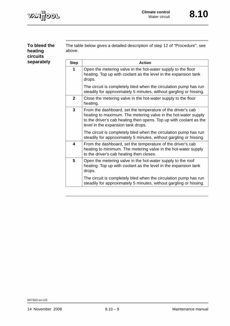
Climate controlWater circuit 8.10
To bleed the heating circuits separately
The table below gives a detailed description of step 12 of "Procedure", see above.
Step Action
1 Open the metering valve in the hot-water supply to the floor heating. Top up with coolant as the level in the expansion tank drops.
The circuit is completely bled when the circulation pump has run steadily for approximately 5 minutes, without gargling or hissing.
2 Close the metering valve in the hot-water supply to the floor heating.
3 From the dashboard, set the temperature of the driver's cab heating to maximum. The metering valve in the hot-water supply to the driver's cab heating then opens. Top up with coolant as the level in the expansion tank drops.
The circuit is completely bled when the circulation pump has run steadily for approximately 5 minutes, without gargling or hissing.
4 From the dashboard, set the temperature of the driver's cab heating to minimum. The metering valve in the hot-water supply to the driver's cab heating then closes.
5 Open the metering valve in the hot-water supply to the roof heating. Top up with coolant as the level in the expansion tank drops.
The circuit is completely bled when the circulation pump has run steadily for approximately 5 minutes, without gargling or hissing.
007303 en-US
14 November 2008 Maintenance manual
.
8.10 – 9
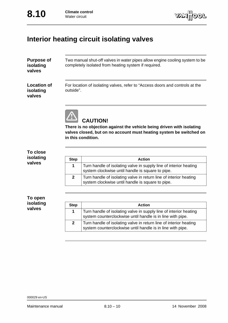
8.10 Climate controlWater circuit
Interior heating circuit isolating valves
Purpose of isolating valves
Two manual shut-off valves in water pipes allow engine cooling system to be completely isolated from heating system if required.
Location of isolating valves
For location of isolating valves, refer to “Access doors and controls at the outside”.
CAUTION!There is no objection against the vehicle being driven with isolating valves closed, but on no account must heating system be switched on in this condition.
To close isolating valves
To open isolating valves
Step Action
1 Turn handle of isolating valve in supply line of interior heating system clockwise until handle is square to pipe.
2 Turn handle of isolating valve in return line of interior heating system clockwise until handle is square to pipe.
Step Action
1 Turn handle of isolating valve in supply line of interior heating system counterclockwise until handle is in line with pipe.
2 Turn handle of isolating valve in return line of interior heating system counterclockwise until handle is in line with pipe.
000029 en-US
Maintenance manual 14 November 2008
.
8.10 – 10
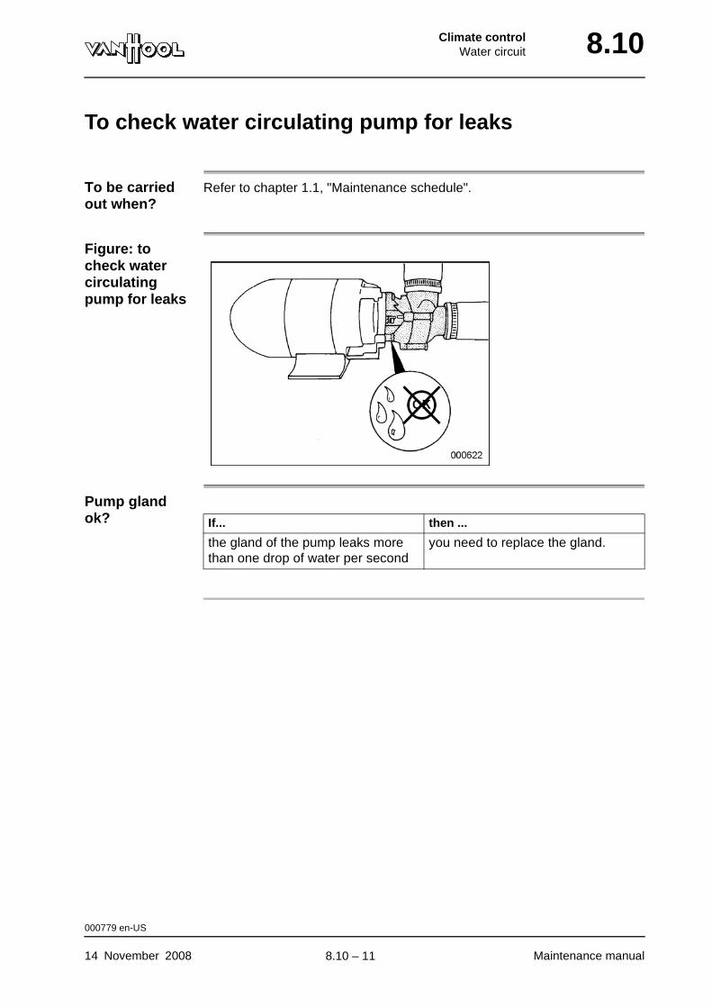
Climate controlWater circuit 8.10
To check water circulating pump for leaks
To be carried out when?
Refer to chapter 1.1, "Maintenance schedule".
Figure: to check water circulating pump for leaks
Pump gland ok? If... then ...
the gland of the pump leaks more than one drop of water per second
you need to replace the gland.
000779 en-US
14 November 2008 Maintenance manual
.
8.10 – 11
8.10 Climate controlWater circuit
To check condition of water hoses
Cross-reference
Refer to chapter 2.34, “Cooling system”.
000780 en-US
Maintenance manual 14 November 2008
.
8.10 – 12
Climate controlWater circuit 8.10
Hose clamp types
Cross-reference
Refer to chapter 2.34, “Cooling system”.
000781 en-US
14 November 2008 Maintenance manual
.
8.10 – 13
8.10 Climate controlWater circuit
To check hose clamps tightening torque
Cross-reference
Refer to chapter 2.34, “Cooling system”.
000782 en-US
Maintenance manual 14 November 2008
.
8.10 – 14
Climate controlRefrigerant circuit 8.14
Chapter 14: Refrigerant circuit
Overview
Introduction This chapter deals with the refrigerant circuit.
Number of pages
38
Chapter publi-cation date
2 January 2008
Contents
Topic See page
Safety instructions when working on refrigerant circuit 8.14-3
Operation 8.14-4
To connect pressure gauge set 8.14-6
To disconnect pressure gauge set 8.14-9
To check refrigerant charge 8.14-12
To add refrigerant 8.14-15
To flush refrigerant circuit 8.14-16
Climate-control compressor: general 8.14-17
Climate-control compressor: capacity control 8.14-18
Climate-control compressor: oil level check 8.14-19
Climate-control compressor: to add oil 8.14-20
To replace the climate-control compressor 8.14-22
Climate-control compressor: electromagnetic clutch 8.14-23
Climate-control compressor: to activate clutch during cold season.
8.14-24
Evaporators 8.14-26
Condenser 8.14-27
To change filter/dryer 8.14-28
Thermostatic expansion valve: general 8.14-30
Service valves: general 8.14-33
Solenoid shut-off valves 8.14-35
Pressure switches 8.14-36
Technical data of refrigerant circuit 8.14-38
2 January 2008 Maintenance manual
continued on next page.
8.14 – 1
8.14 Climate controlRefrigerant circuit
Maintenance manual 2 January 2008
.
8.14 – 2
Climate controlRefrigerant circuit 8.14
Safety instructions when working on refrigerant circuit
WARNING!Maintenance and repair works should only be carried out by a refriger-ation technician.
WARNING!The refrigerant circuit is pressurised.
WARNING!Never work with refrigerant in a confined space or near an open fire.
WARNING!Make sure that your eyes and skin do not come in contact with the refrigerant. In the event of contact with the eyes, rinse the eyes with ample water. In the event of contact with skin, apply pure vaseline to the affected spot. Always consult a physician.
000641 en-US
2 January 2008 Maintenance manual
.
8.14 – 3
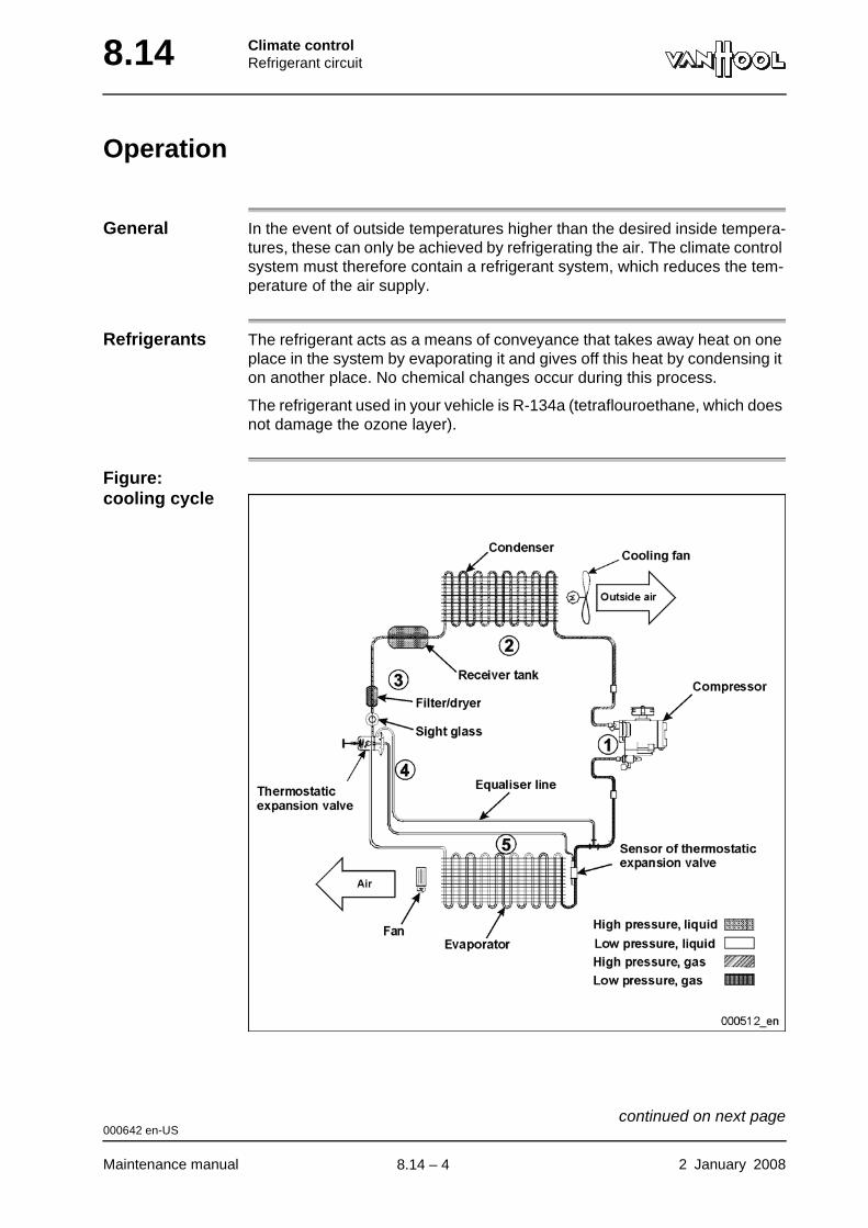
8.14 Climate controlRefrigerant circuit
Operation
General In the event of outside temperatures higher than the desired inside tempera-tures, these can only be achieved by refrigerating the air. The climate control system must therefore contain a refrigerant system, which reduces the tem-perature of the air supply.
Refrigerants The refrigerant acts as a means of conveyance that takes away heat on one place in the system by evaporating it and gives off this heat by condensing it on another place. No chemical changes occur during this process.
The refrigerant used in your vehicle is R-134a (tetraflouroethane, which does not damage the ozone layer).
Figure: cooling cycle
000642 en-US
Maintenance manual 2 January 2008
continued on next page.
8.14 – 4

Climate controlRefrigerant circuit 8.14
Cooling cyclePhase Name Description
1 Compression The gaseous refrigerant is compressed into the compressor. This causes both the pressure and the temperature of the gas to rise.
2 Cooling In the condenser, the gas gives off heat to the surrounding air and condenses into a liquid.
NOTE: Cooling can be speeded with fans
3 Storage The fluid tank stores the refrigerant (in liquid and in gaseous state) coming from the condenser. It remains in this tank, until the evaporator requires refrigerant.
4 Filtration/drying Humidity and dirt from the refrigerant circuit are caught in the filter/dryer.
5 Flow control The thermostatic expansion valve permits just enough liquid refrigerant to flow to the evaporator. Here the temperature and pressure of the liquid refrigerant decline, and a part of the refrigerant takes on a gaseous form.
6 Evaporation The partially liquid and partially gaseous refrigerant, which has a lower pressure and temperature, flows to the evaporator. The refrigerant continues to evaporate by extracting heat from the air flow, which passes through the evaporator coil. All the liquid refrigerant is converted into a gaseous form in the evaporator, and only the warmed gaseous refrigerant flows to the compressor.
000642 en-US
2 January 2008 Maintenance manual
.
8.14 – 5
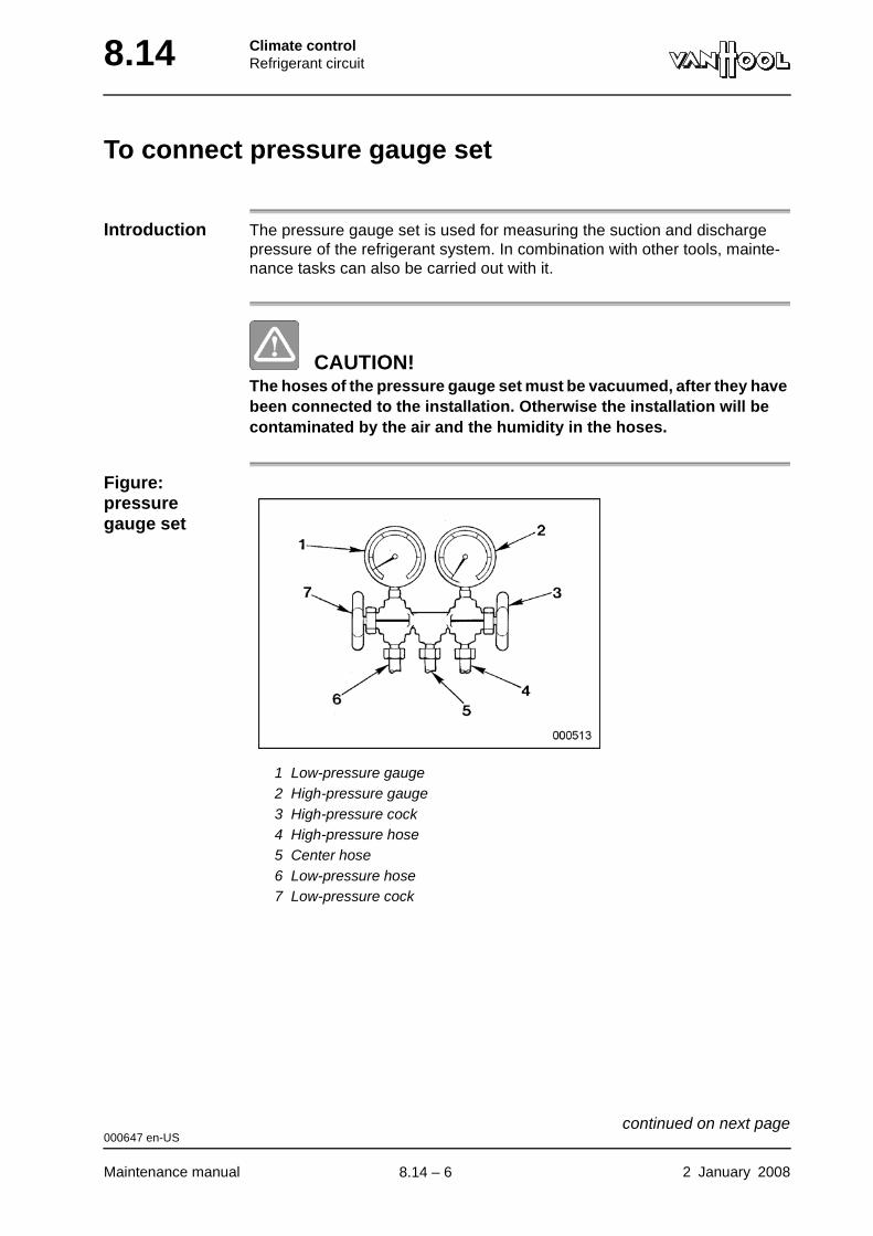
8.14 Climate controlRefrigerant circuit
To connect pressure gauge set
Introduction The pressure gauge set is used for measuring the suction and discharge pressure of the refrigerant system. In combination with other tools, mainte-nance tasks can also be carried out with it.
CAUTION!The hoses of the pressure gauge set must be vacuumed, after they have been connected to the installation. Otherwise the installation will be contaminated by the air and the humidity in the hoses.
Figure: pressure gauge set
1 Low-pressure gauge2 High-pressure gauge3 High-pressure cock4 High-pressure hose5 Center hose6 Low-pressure hose7 Low-pressure cock
000647 en-US
Maintenance manual 2 January 2008
continued on next page.
8.14 – 6
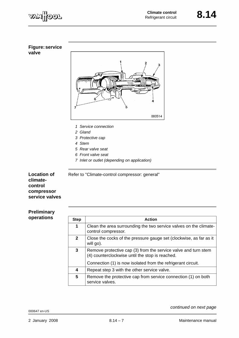
Climate controlRefrigerant circuit 8.14
Figure: service valve
1 Service connection2 Gland3 Protective cap4 Stem5 Rear valve seat6 Front valve seat7 Inlet or outlet (depending on application)
Location of climate-control compressor service valves
Refer to "Climate-control compressor: general"
Preliminary operations Step Action
1 Clean the area surrounding the two service valves on the climate-control compressor.
2 Close the cocks of the pressure gauge set (clockwise, as far as it will go).
3 Remove protective cap (3) from the service valve and turn stem (4) counterclockwise until the stop is reached.
Connection (1) is now isolated from the refrigerant circuit.
4 Repeat step 3 with the other service valve.
5 Remove the protective cap from service connection (1) on both service valves.
000647 en-US
2 January 2008 Maintenance manual
continued on next page.
8.14 – 7
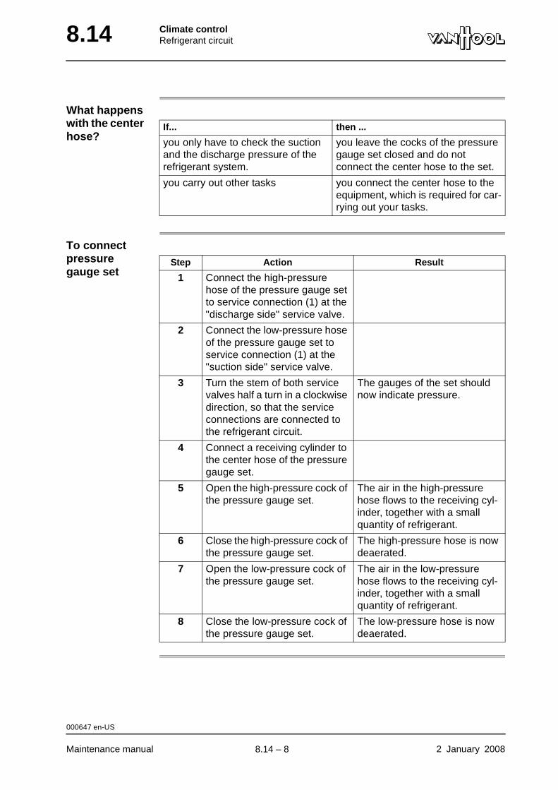
8.14 Climate controlRefrigerant circuit
What happens with the center hose?
To connect pressure gauge set
If... then ...
you only have to check the suction and the discharge pressure of the refrigerant system.
you leave the cocks of the pressure gauge set closed and do not connect the center hose to the set.
you carry out other tasks you connect the center hose to the equipment, which is required for car-rying out your tasks.
Step Action Result
1 Connect the high-pressure hose of the pressure gauge set to service connection (1) at the "discharge side" service valve.
2 Connect the low-pressure hose of the pressure gauge set to service connection (1) at the "suction side" service valve.
3 Turn the stem of both service valves half a turn in a clockwise direction, so that the service connections are connected to the refrigerant circuit.
The gauges of the set should now indicate pressure.
4 Connect a receiving cylinder to the center hose of the pressure gauge set.
5 Open the high-pressure cock of the pressure gauge set.
The air in the high-pressure hose flows to the receiving cyl-inder, together with a small quantity of refrigerant.
6 Close the high-pressure cock of the pressure gauge set.
The high-pressure hose is now deaerated.
7 Open the low-pressure cock of the pressure gauge set.
The air in the low-pressure hose flows to the receiving cyl-inder, together with a small quantity of refrigerant.
8 Close the low-pressure cock of the pressure gauge set.
The low-pressure hose is now deaerated.
000647 en-US
Maintenance manual 2 January 2008
.
8.14 – 8

Climate controlRefrigerant circuit 8.14
To disconnect pressure gauge set
CAUTION!The hoses of the pressure gauge set must be emptied before they are disconnected, to prevent that refrigerant escapes.
Figure: pressure gauge set
1 Low-pressure gauge2 High-pressure gauge3 High-pressure cock4 High-pressure hose5 Center hose6 Low-pressure hose7 Low-pressure cock
000648 en-US
2 January 2008 Maintenance manual
continued on next page.
8.14 – 9
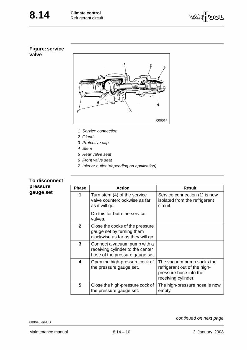
8.14 Climate controlRefrigerant circuit
Figure: service valve
1 Service connection2 Gland3 Protective cap4 Stem5 Rear valve seat6 Front valve seat7 Inlet or outlet (depending on application)
To disconnect pressure gauge set
Phase Action Result
1 Turn stem (4) of the service valve counterclockwise as far as it will go.
Do this for both the service valves.
Service connection (1) is now isolated from the refrigerant circuit.
2 Close the cocks of the pressure gauge set by turning them clockwise as far as they will go.
3 Connect a vacuum pump with a receiving cylinder to the center hose of the pressure gauge set.
4 Open the high-pressure cock of the pressure gauge set.
The vacuum pump sucks the refrigerant out of the high-pressure hose into the receiving cylinder.
5 Close the high-pressure cock of the pressure gauge set.
The high-pressure hose is now empty.
000648 en-US
Maintenance manual 2 January 2008
continued on next page.
8.14 – 10
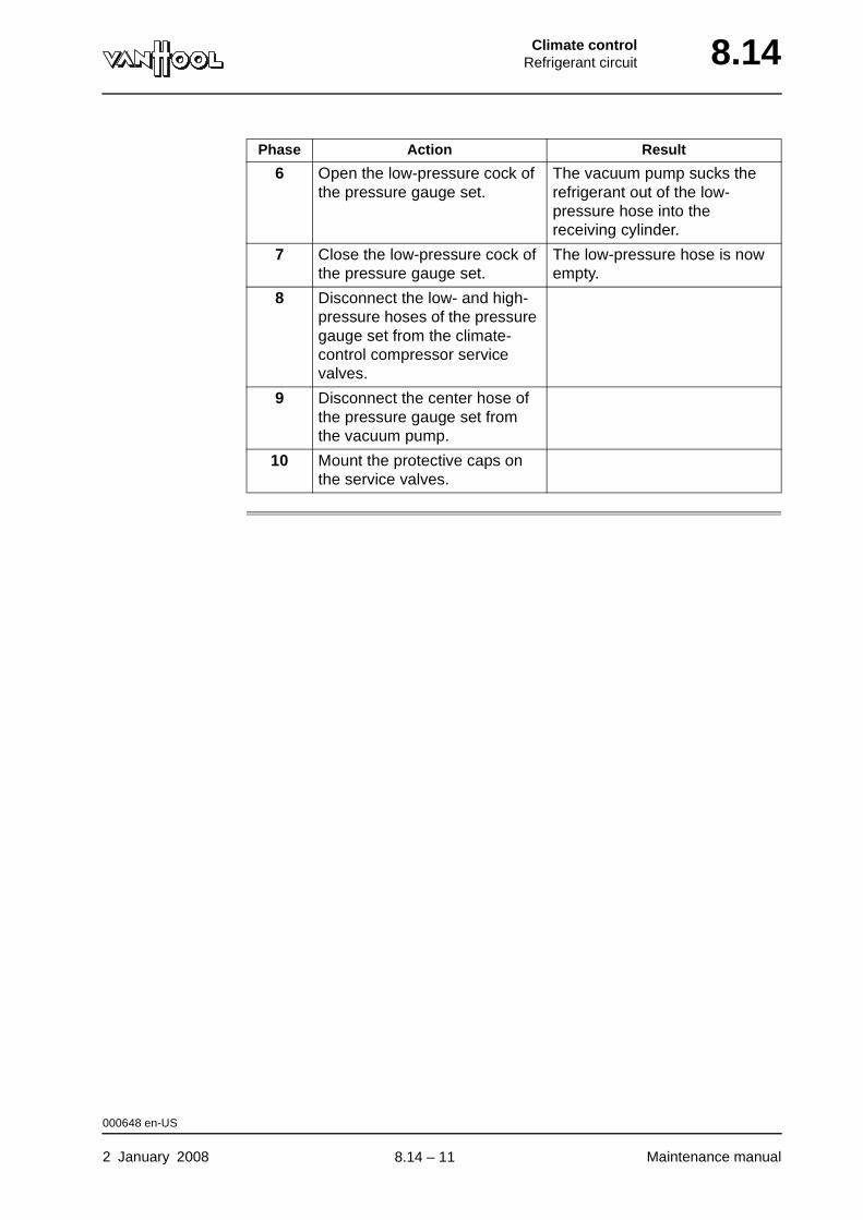
Climate controlRefrigerant circuit 8.14
6 Open the low-pressure cock of the pressure gauge set.
The vacuum pump sucks the refrigerant out of the low-pressure hose into the receiving cylinder.
7 Close the low-pressure cock of the pressure gauge set.
The low-pressure hose is now empty.
8 Disconnect the low- and high-pressure hoses of the pressure gauge set from the climate-control compressor service valves.
9 Disconnect the center hose of the pressure gauge set from the vacuum pump.
10 Mount the protective caps on the service valves.
Phase Action Result
000648 en-US
2 January 2008 Maintenance manual
.
8.14 – 11
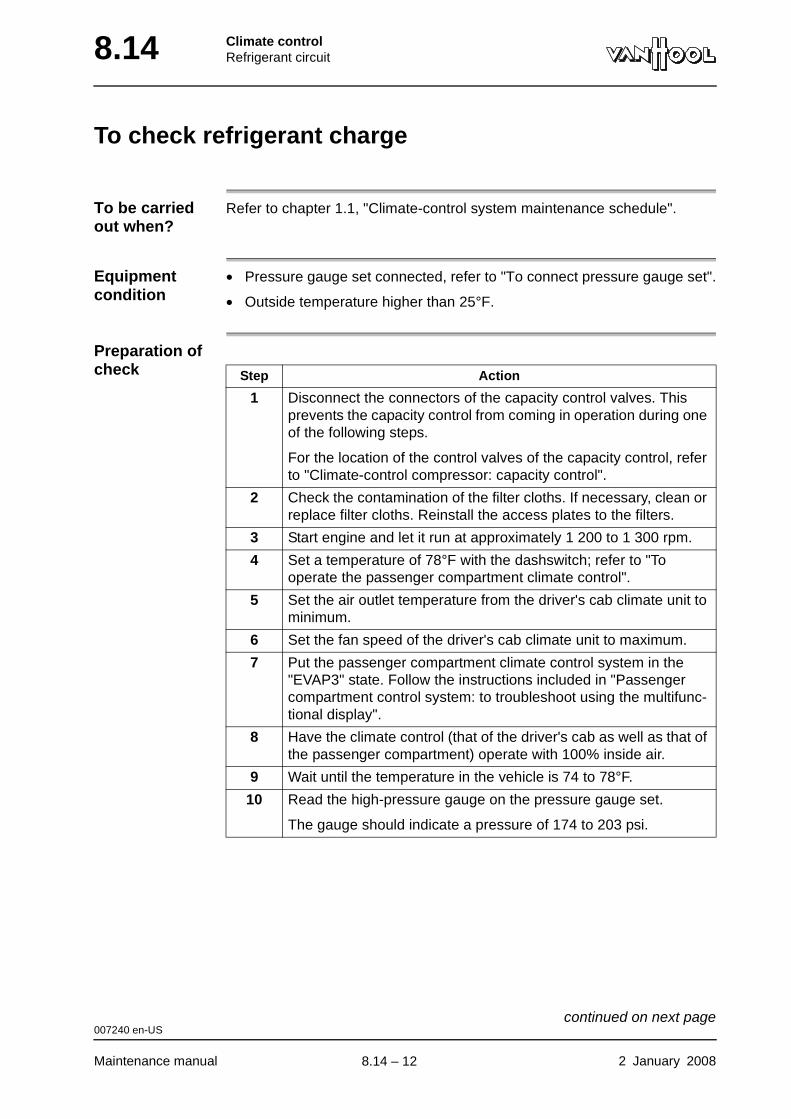
8.14 Climate controlRefrigerant circuit
To check refrigerant charge
To be carried out when?
Refer to chapter 1.1, "Climate-control system maintenance schedule".
Equipment condition
• Pressure gauge set connected, refer to "To connect pressure gauge set".
• Outside temperature higher than 25°F.
Preparation of check Step Action
1 Disconnect the connectors of the capacity control valves. This prevents the capacity control from coming in operation during one of the following steps.
For the location of the control valves of the capacity control, refer to "Climate-control compressor: capacity control".
2 Check the contamination of the filter cloths. If necessary, clean or replace filter cloths. Reinstall the access plates to the filters.
3 Start engine and let it run at approximately 1 200 to 1 300 rpm.
4 Set a temperature of 78°F with the dashswitch; refer to "To operate the passenger compartment climate control".
5 Set the air outlet temperature from the driver's cab climate unit to minimum.
6 Set the fan speed of the driver's cab climate unit to maximum.
7 Put the passenger compartment climate control system in the "EVAP3" state. Follow the instructions included in "Passenger compartment control system: to troubleshoot using the multifunc-tional display".
8 Have the climate control (that of the driver's cab as well as that of the passenger compartment) operate with 100% inside air.
9 Wait until the temperature in the vehicle is 74 to 78°F.
10 Read the high-pressure gauge on the pressure gauge set.
The gauge should indicate a pressure of 174 to 203 psi.
007240 en-US
Maintenance manual 2 January 2008
continued on next page.
8.14 – 12
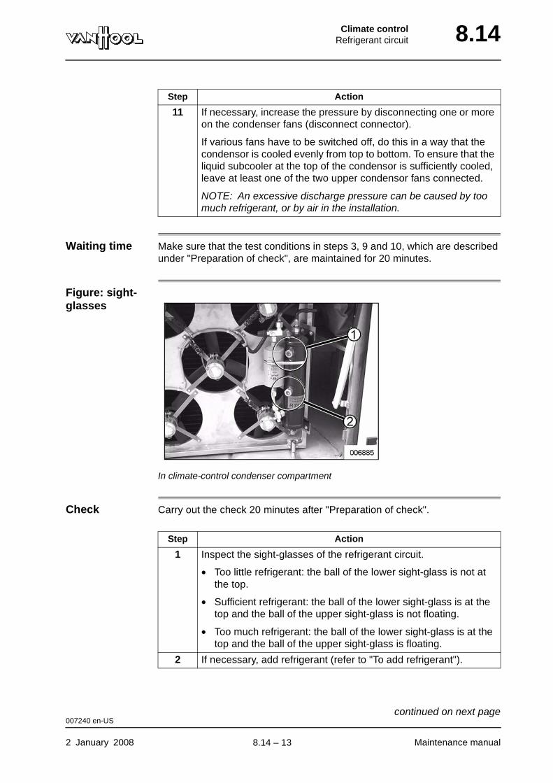
Climate controlRefrigerant circuit 8.14
Waiting time Make sure that the test conditions in steps 3, 9 and 10, which are described under "Preparation of check", are maintained for 20 minutes.
Figure: sight-glasses
In climate-control condenser compartment
Check Carry out the check 20 minutes after "Preparation of check".
11 If necessary, increase the pressure by disconnecting one or more on the condenser fans (disconnect connector).
If various fans have to be switched off, do this in a way that the condensor is cooled evenly from top to bottom. To ensure that the liquid subcooler at the top of the condensor is sufficiently cooled, leave at least one of the two upper condensor fans connected.
NOTE: An excessive discharge pressure can be caused by too much refrigerant, or by air in the installation.
Step Action
Step Action
1 Inspect the sight-glasses of the refrigerant circuit.
• Too little refrigerant: the ball of the lower sight-glass is not at the top.
• Sufficient refrigerant: the ball of the lower sight-glass is at the top and the ball of the upper sight-glass is not floating.
• Too much refrigerant: the ball of the lower sight-glass is at the top and the ball of the upper sight-glass is floating.
2 If necessary, add refrigerant (refer to "To add refrigerant").
007240 en-US
2 January 2008 Maintenance manual
continued on next page.
8.14 – 13
8.14 Climate controlRefrigerant circuit
3 Reconnect the disconnected condensor fans and the pilot valves of the capacity control.
4 Disconnect the pressure gauge set; refer to "To disconnect the pressure gauge set".
Step Action
007240 en-US
Maintenance manual 2 January 2008
.
8.14 – 14
Climate controlRefrigerant circuit 8.14
To add refrigerant
Equipment condition
Steps mentioned under "To check refrigerant charge" carried out.
Procedure
Step Action
1 Connect the center hose of the pressure gauge set to a charging cylinder.
2 Open the cock of the charging cylinder.
3 Loosen the union nut of the center hose just below the gauge set to purge the hose. Tighten the union nut after purging.
4 Open the low-pressure cock of the pressure gauge set a little.
Refrigerant flows from the charging cylinder to the system.
5 Close the low pressure cock of the pressure gauge set if the circuit is properly charged; refer to "To check refrigerant charge".
000645 en-US
2 January 2008 Maintenance manual
.
8.14 – 15
8.14 Climate controlRefrigerant circuit
To flush refrigerant circuit
Introduction "Flushing" means the removal of air and other contaminations from the instal-lation. This is performed by blowing nitrogen through the system.
000653 en-US
Maintenance manual 2 January 2008
.
8.14 – 16
Climate controlRefrigerant circuit 8.14
Climate-control compressor: general
Drive The vehicle engine drives the refrigerant compressor by means of two belts and a disconnectable clutch.
Refer to chapter 2.46 "Accessory drive system" for more information about the belt drive.
Compressor oil
The compressor circulates an amount of compressor oil together with the refrigerant.
It has hardly any disadvantageous influence on the system if the amount of oil which is brought in the refrigerant circuit by the compressor is very small. It is even good because the compressor valves will be lubricated.
On the other hand, the following problems can occur if a too large amount of oil circulates in the system:
• Because oil is withdrawn from the compressor sump, lubrication of the compressor can be insufficient. The compressor can seize.
• The amount of oil which circulates with the refrigerant is not constant. The oil can accumulate in the evaporator, which can cause a sudden release of a large amount of oil to the compressor. Oil that is accumulated in the evaporator reduces the heat transfer whereby the cooling capacity reduces.
006210 en-US
2 January 2008 Maintenance manual
.
8.14 – 17
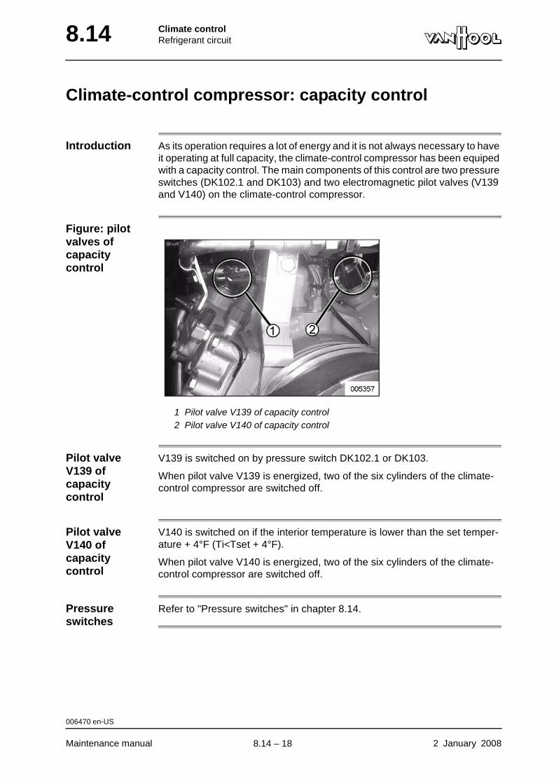
8.14 Climate controlRefrigerant circuit
Climate-control compressor: capacity control
Introduction As its operation requires a lot of energy and it is not always necessary to have it operating at full capacity, the climate-control compressor has been equiped with a capacity control. The main components of this control are two pressure switches (DK102.1 and DK103) and two electromagnetic pilot valves (V139 and V140) on the climate-control compressor.
Figure: pilot valves of capacity control
1 Pilot valve V139 of capacity control2 Pilot valve V140 of capacity control
Pilot valve V139 of capacity control
V139 is switched on by pressure switch DK102.1 or DK103.
When pilot valve V139 is energized, two of the six cylinders of the climate-control compressor are switched off.
Pilot valve V140 of capacity control
V140 is switched on if the interior temperature is lower than the set temper-ature + 4°F (Ti<Tset + 4°F).
When pilot valve V140 is energized, two of the six cylinders of the climate-control compressor are switched off.
Pressure switches
Refer to "Pressure switches" in chapter 8.14.
006470 en-US
Maintenance manual 2 January 2008
.
8.14 – 18
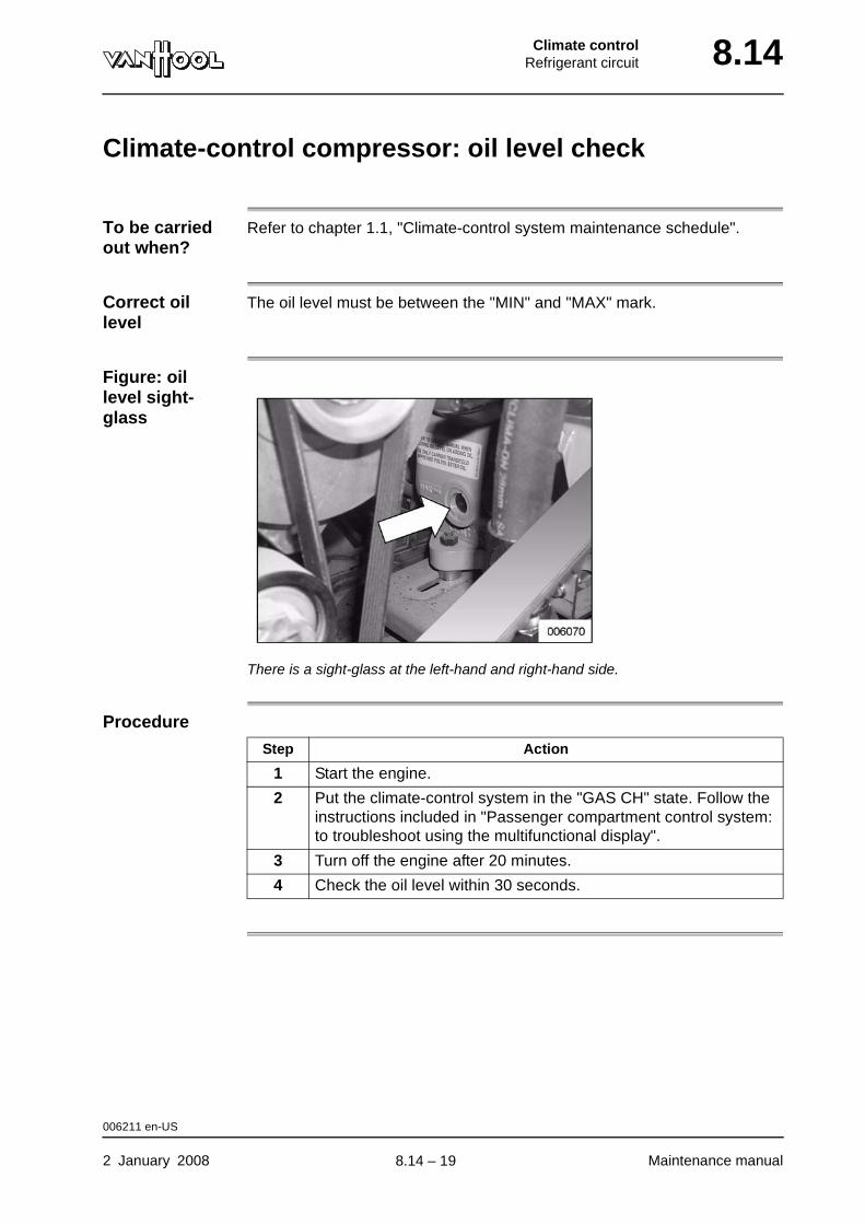
Climate controlRefrigerant circuit 8.14
Climate-control compressor: oil level check
To be carried out when?
Refer to chapter 1.1, "Climate-control system maintenance schedule".
Correct oil level
The oil level must be between the "MIN" and "MAX" mark.
Figure: oil level sight-glass
There is a sight-glass at the left-hand and right-hand side.
Procedure
Step Action
1 Start the engine.
2 Put the climate-control system in the "GAS CH" state. Follow the instructions included in "Passenger compartment control system: to troubleshoot using the multifunctional display".
3 Turn off the engine after 20 minutes.
4 Check the oil level within 30 seconds.
006211 en-US
2 January 2008 Maintenance manual
.
8.14 – 19

8.14 Climate controlRefrigerant circuit
Climate-control compressor: to add oil
Oil type Refer to chapter 1.1, "Fluids and lubricants".
Oil loss? The climate-control compressor does not consume oil. Nevertheless, if it is necessary to add oil, this usually means that there is a leak in the refrigerant circuit. Check the refrigerant circuit for leaks first.
Equipment condition
Pressure gauge set connected, refer to "To connect pressure gauge set" in the present chapter.
To add oil
Step Action
1 Turn the stem of the "suction side" service valve counterclockwise as far as it will go.
The "suction side" service valve is now closed.
2 Turn the cocks of the pressure gauge set fully clockwise.
The cocks are now closed.
3 Fill the low-pressure hose and the center hose of the pressure gauge set with oil.
4 Secure the low-pressure hose of the pressure gauge set to the service connection of the "suction side" service valve.
5 Immerse the loose end of the center hose in a can of climate-control compressor oil.
6 Turn the stem of the "suction side" service valve clockwise as far as it will go.
The service connection is now connected to the refrigerant circuit.
7 Start the engine.
8 Let the compressor run until the low-pressure switch cuts out the climate-control compressor clutch.
9 Shut off the engine.
10 Open the low-pressure cock of the pressure gauge set a little.
The oil is sucked into the climate-control compressor.
11 Close the low pressure cock, when the correct oil level is reached.
12 Turn the stem of the "suction side" service valve counterclockwise as far as it will go.
The service connection is now isolated from the refrigerant circuit.
000655 en-US
Maintenance manual 2 January 2008
continued on next page.
8.14 – 20
Climate controlRefrigerant circuit 8.14
000655 en-US
2 January 2008 Maintenance manual
.
8.14 – 21
8.14 Climate controlRefrigerant circuit
To replace the climate-control compressor
WARNING!The refrigerant circuit is pressurised. First relieve the pressure, before you carry out any works on the compressor. Also see to it that no one can start the engine.
Dirt and humidity
The main enemies of a refrigerant system are dirt and humidity. During the installation of a new compressor, the protective gas must remain in the com-pressor as long as possible. Then take the necessary measures for pro-tecting the compressor against dirt and humidity.
How much oil in the new compressor?
When changing the compressor, the new compressor must be taken into operation with the same quantity of oil as the quantity present in the removed compressor. New compressors are usually supplied with a standard quantity of oil; you will therefore probably have to remove a certain quantity of oil from the compressor.
000646 en-US
Maintenance manual 2 January 2008
.
8.14 – 22
Climate controlRefrigerant circuit 8.14
Climate-control compressor: electromagnetic clutch
Compressor clutch V141
An electromagnetic clutch is applied for switching the connection between the engine and the compressor on and off.
The stator, the rotor with a belt pulley and the pressure plate are the primary components. The stator is fixed to the compressor housing and the pressure plate is mounted on the compressor shaft.
The belt pulley always rotates when the engine is running because it is con-nected to the engine crankshaft by means of drive belts. But the compressor only begins to operate, when the electromagnetic clutch is energised. Whenever cooling is required, the control unit sends an electrical current to the magnetic coil. The electomagnet pulls the pressure plate against the friction plates of the belt pulley. Due to the friction between the plates, the clutch components will rotate as a whole and drive the compressor.
When does the clutch cut in?
NOTE: The clutch only cuts in when the on-board voltage is higher than 21.6 V and the compressed-air system is pressurised.
The clutch cuts in if:
• outside temperature exceeds 25°F and...
• the roof-heating metering valve is closed for more than 40 % of the time.
NOTE: Pressure switches DK101 or DK102.2 switch the clutch off if the pressure in the refrigerant circuit becomes too low or too high.
007241 en-US
2 January 2008 Maintenance manual
.
8.14 – 23
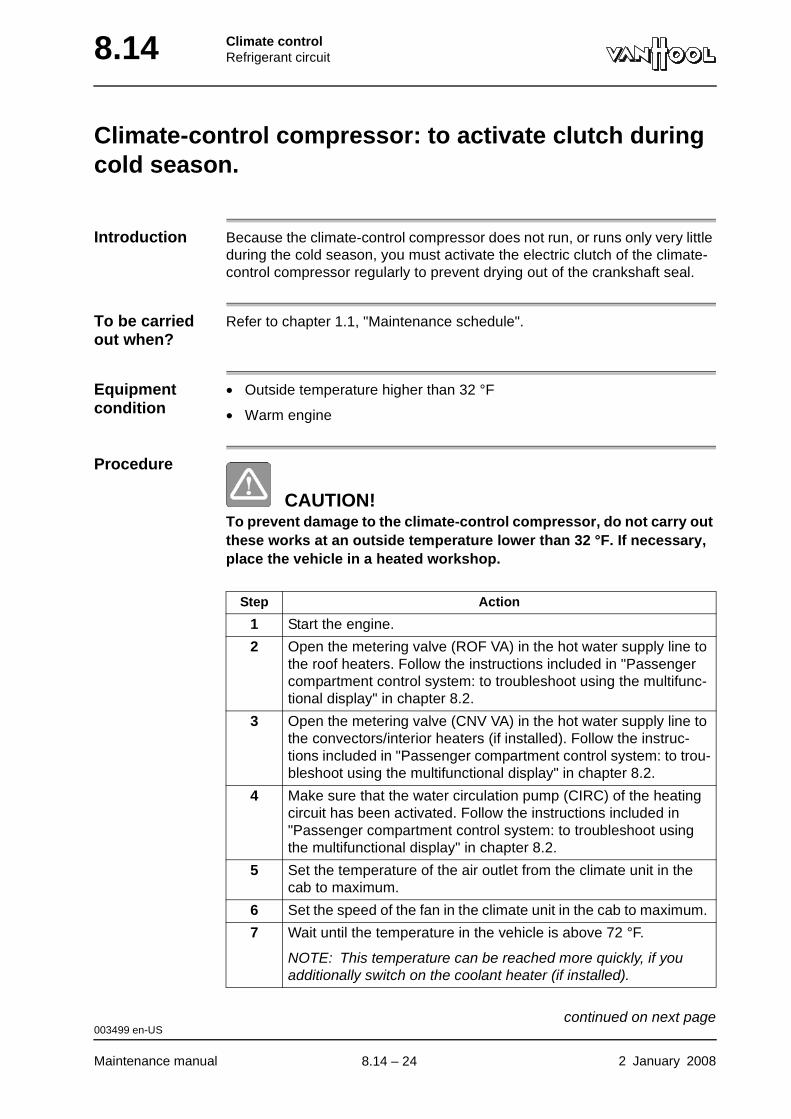
8.14 Climate controlRefrigerant circuit
Climate-control compressor: to activate clutch during cold season.
Introduction Because the climate-control compressor does not run, or runs only very little during the cold season, you must activate the electric clutch of the climate-control compressor regularly to prevent drying out of the crankshaft seal.
To be carried out when?
Refer to chapter 1.1, "Maintenance schedule".
Equipment condition
• Outside temperature higher than 32 °F
• Warm engine
Procedure
CAUTION!To prevent damage to the climate-control compressor, do not carry out these works at an outside temperature lower than 32 °F. If necessary, place the vehicle in a heated workshop.
Step Action
1 Start the engine.
2 Open the metering valve (ROF VA) in the hot water supply line to the roof heaters. Follow the instructions included in "Passenger compartment control system: to troubleshoot using the multifunc-tional display" in chapter 8.2.
3 Open the metering valve (CNV VA) in the hot water supply line to the convectors/interior heaters (if installed). Follow the instruc-tions included in "Passenger compartment control system: to trou-bleshoot using the multifunctional display" in chapter 8.2.
4 Make sure that the water circulation pump (CIRC) of the heating circuit has been activated. Follow the instructions included in "Passenger compartment control system: to troubleshoot using the multifunctional display" in chapter 8.2.
5 Set the temperature of the air outlet from the climate unit in the cab to maximum.
6 Set the speed of the fan in the climate unit in the cab to maximum.
7 Wait until the temperature in the vehicle is above 72 °F.
NOTE: This temperature can be reached more quickly, if you additionally switch on the coolant heater (if installed).
003499 en-US
Maintenance manual 2 January 2008
continued on next page.
8.14 – 24
Climate controlRefrigerant circuit 8.14
8 Put the climate control in the "GAS CH" state. Follow the instruc-tions included in "Passenger compartment control system: to trou-bleshoot using the multifunctional display".
The clutch of the climate-control compressor is activated.
9
WARNING!The engine turns! Keep your distance from turning parts.
Check that the core of the electric clutch turns along with the belt pulley. This confirms that the electric clutch is switched on.
10 Turn off the engine after 15 minutes.
11 Switch off the battery isolating switch.
The electronics of the climate-control system return to automatic mode.
Step Action
003499 en-US
2 January 2008 Maintenance manual
.
8.14 – 25
8.14 Climate controlRefrigerant circuit
Evaporators
Introduction The refrigerant evaporates in the evaporator unit by absorbing heat from the surroundings.
The passenger compartment is cooled by two evaporators in the roof ducts. The cab is cooled by an evaporator in the climate-control unit of the cab.
000671 en-US
Maintenance manual 2 January 2008
.
8.14 – 26
Climate controlRefrigerant circuit 8.14
Condenser
Introduction The hot refrigerant gas, which has been compressed by the compressor, is cooled in the condenser until it becomes a fluid.
Fans speed up the heat exchange in the condensor.
To clean the condensor externally WARNING!
Wear a dust mask, when cleaning with compressed air.
Check the condensor regularly for contamination (leaves, dust, ...). . If nec-essary, blow the condensor through with compressed air (approx. 116 psi pressure).
Condensor suspension maintenance
The suspension system makes it possible to fold out the condensor for main-tenance.
To prevent some of the suspension elements from seizing after a while, perform the following maintenance works regularly.
Condensor fans speed control
The condenser fans will switch to low speed when the climate-control com-pressor clutch is switched on. They switch to high speed if the interior tem-perature exceeds the set temperature 4°F (Ti>Tset 4°F).
Speed is controlled by connecting the fans in series/parallel.
NOTE: The condensor fans will keep on running when the climate-control compressor clutch is switched off by high-pressure switch DK102.2.
Step Action
1 Apply a drop of oil to the latches that keep the condensor in its place.
2 Only for hinges with a grease nipple: press grease into the grease nipple of the two condensor suspension hinges.
007244 en-US
2 January 2008 Maintenance manual
.
8.14 – 27
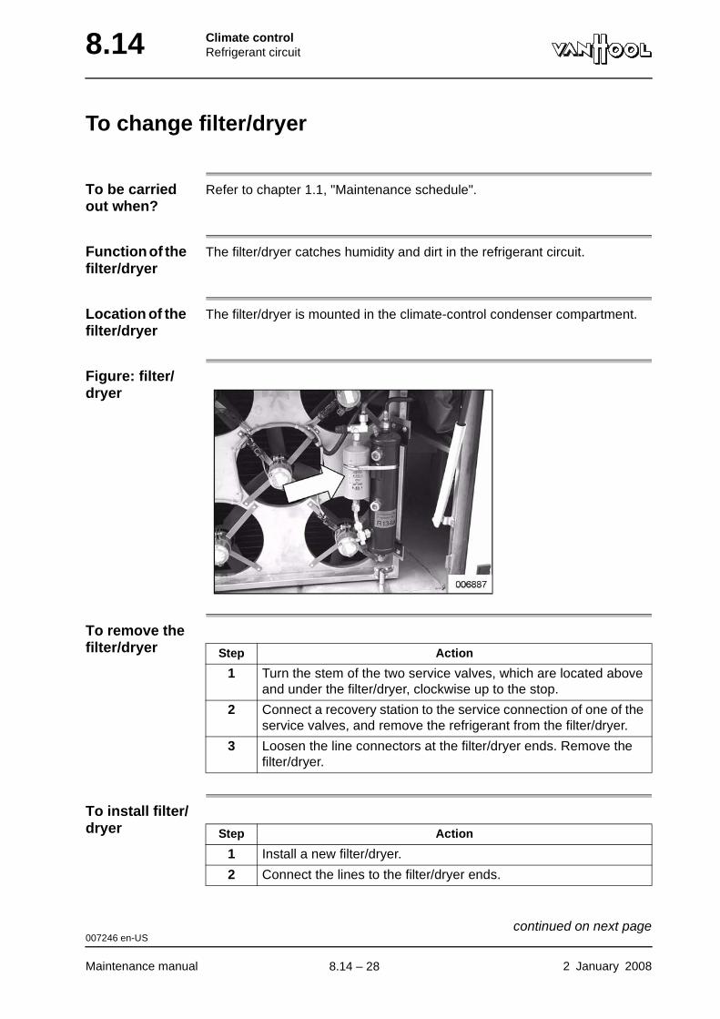
8.14 Climate controlRefrigerant circuit
To change filter/dryer
To be carried out when?
Refer to chapter 1.1, "Maintenance schedule".
Function of the filter/dryer
The filter/dryer catches humidity and dirt in the refrigerant circuit.
Location of the filter/dryer
The filter/dryer is mounted in the climate-control condenser compartment.
Figure: filter/dryer
To remove the filter/dryer
To install filter/dryer
Step Action
1 Turn the stem of the two service valves, which are located above and under the filter/dryer, clockwise up to the stop.
2 Connect a recovery station to the service connection of one of the service valves, and remove the refrigerant from the filter/dryer.
3 Loosen the line connectors at the filter/dryer ends. Remove the filter/dryer.
Step Action
1 Install a new filter/dryer.
2 Connect the lines to the filter/dryer ends.
007246 en-US
Maintenance manual 2 January 2008
continued on next page.
8.14 – 28
Climate controlRefrigerant circuit 8.14
3 Vacuum down the filter/dryer.
4 Turn the stem of the two service valves, which are located above and under the filter/dryer, counterclockwise up to the stop.
5 Check for leaks
Step Action
007246 en-US
2 January 2008 Maintenance manual
.
8.14 – 29
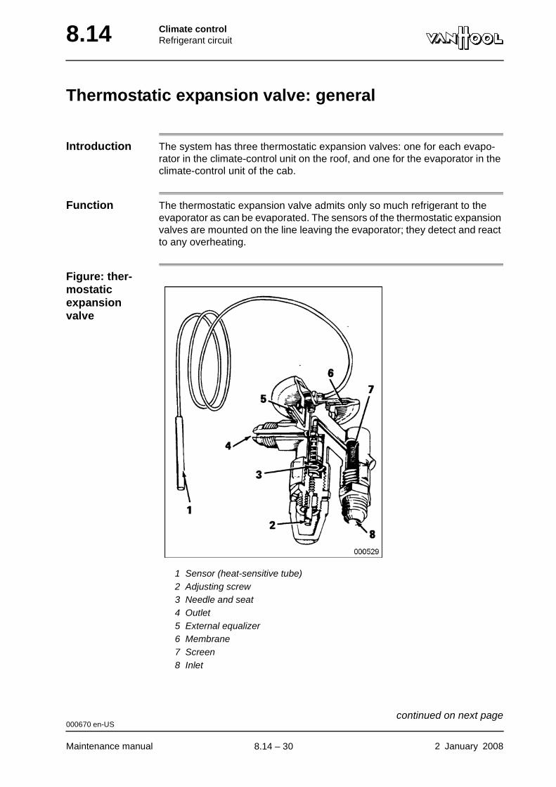
8.14 Climate controlRefrigerant circuit
Thermostatic expansion valve: general
Introduction The system has three thermostatic expansion valves: one for each evapo-rator in the climate-control unit on the roof, and one for the evaporator in the climate-control unit of the cab.
Function The thermostatic expansion valve admits only so much refrigerant to the evaporator as can be evaporated. The sensors of the thermostatic expansion valves are mounted on the line leaving the evaporator; they detect and react to any overheating.
Figure: ther-mostatic expansion valve
1 Sensor (heat-sensitive tube)2 Adjusting screw3 Needle and seat4 Outlet5 External equalizer6 Membrane7 Screen8 Inlet
000670 en-US
Maintenance manual 2 January 2008
continued on next page.
8.14 – 30
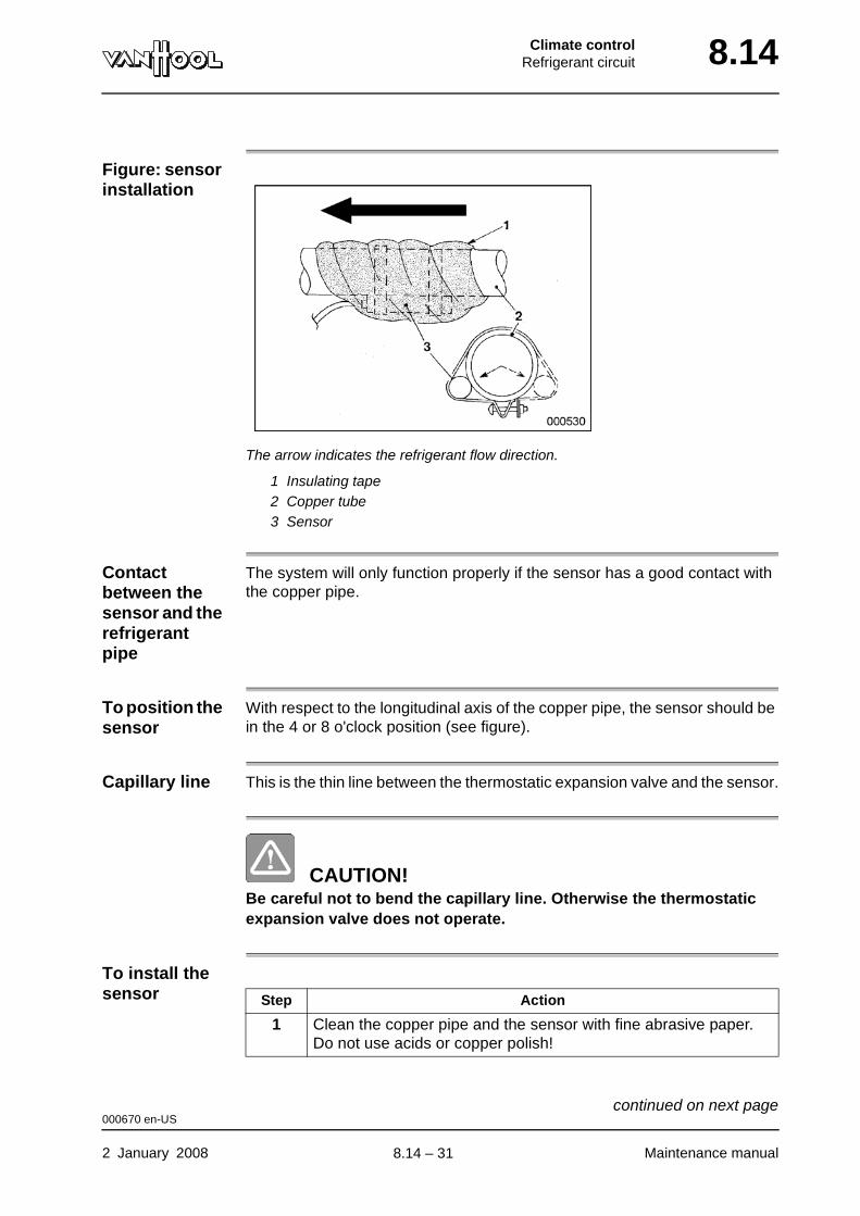
Climate controlRefrigerant circuit 8.14
Figure: sensor installation
The arrow indicates the refrigerant flow direction.
1 Insulating tape2 Copper tube3 Sensor
Contact between the sensor and the refrigerant pipe
The system will only function properly if the sensor has a good contact with the copper pipe.
To position the sensor
With respect to the longitudinal axis of the copper pipe, the sensor should be in the 4 or 8 o'clock position (see figure).
Capillary line This is the thin line between the thermostatic expansion valve and the sensor.
CAUTION!Be careful not to bend the capillary line. Otherwise the thermostatic expansion valve does not operate.
To install the sensor Step Action
1 Clean the copper pipe and the sensor with fine abrasive paper. Do not use acids or copper polish!
000670 en-US
2 January 2008 Maintenance manual
continued on next page.
8.14 – 31
8.14 Climate controlRefrigerant circuit
2 To prevent oxidation, coat sensor and copper pipe with a thin layer of a heat conducting paste.
3 Secure the new sensor to a horizontal part of the pipe, with the help of a few hose clamps. Refer to "To position the sensor".
4 Wrap insulating tape around the sensor and the pipe.
Step Action
000670 en-US
Maintenance manual 2 January 2008
.
8.14 – 32
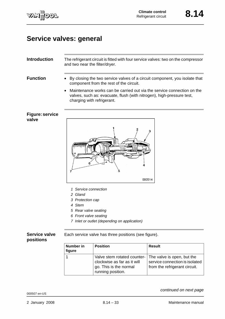
Climate controlRefrigerant circuit 8.14
Service valves: general
Introduction The refrigerant circuit is fitted with four service valves: two on the compressor and two near the filter/dryer.
Function • By closing the two service valves of a circuit component, you isolate that component from the rest of the circuit.
• Maintenance works can be carried out via the service connection on the valves, such as: evacuate, flush (with nitrogen), high-pressure test, charging with refrigerant.
Figure: service valve
1 Service connection2 Gland3 Protection cap4 Stem5 Rear valve seating6 Front valve seating7 Inlet or outlet (depending on application)
Service valve positions
Each service valve has three positions (see figure).
Number in figure
Position Result
1 Valve stem rotated counter-clockwise as far as it will go. This is the normal running position.
The valve is open, but the service connection is isolated from the refrigerant circuit.
000507 en-US
2 January 2008 Maintenance manual
continued on next page.
8.14 – 33
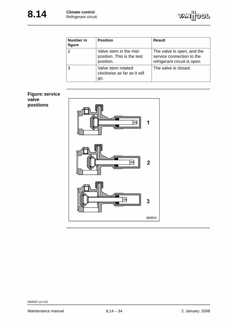
8.14 Climate controlRefrigerant circuit
Figure: service valve positions
2 Valve stem in the mid-position. This is the test position.
The valve is open, and the service connection to the refrigerant circuit is open.
3 Valve stem rotated clockwise as far as it will go.
The valve is closed.
Number in figure
Position Result
000507 en-US
Maintenance manual 2 January 2008
.
8.14 – 34

Climate controlRefrigerant circuit 8.14
Solenoid shut-off valves
Introduction The refrigerant circuit has been equiped with three solenoid shut-off valves.
• Shut-off valve V142 in the line to the driver's cab climate-control unit evap-orator.
• Shut-off valve V144.1 in the line to the evaporator in the LH roof duct of the passenger compartment.
• Shut-off valve V144.2 in the line to the evaporator in the RH roof duct of the passenger compartment.
When do the shut-off valves open?
The "normally closed" solenoid shut-off valves V142, V144.1 and V144.2 will open when the climate-control compressor clutch is switched on.
NOTE: The shut-off valves remain energized when the climate-control com-pressor clutch is switched off by pressure switch DK101.
NOTE: The program prevents shut-off valve V142 from being opened when the fan motor in the driver's cab climate-control unit is not running.
006717 en-US
2 January 2008 Maintenance manual
.
8.14 – 35

8.14 Climate controlRefrigerant circuit
Pressure switches
Introduction In order to monitor and to limit the pressure in the refrigerant circuit, four switches have been installed:
• DK101 and DK102.2 protect the installation against abnormal operating pressures,
• DK102.1 and DK103 switch on the capacity control.
Location of pressure switches
Low-pressure switch DK101
Pressure switch DK101 protects the installation against low operating pressure.
Element Figure
On the climate-control compressor:
1 High-pressure switch DK102.2 of protection system
2 Low-pressure switch DK101 of protection system
On the climate-control compressor: high-pressure switch DK102.1 of capacity control
On the climate-control compressor: low-pressure switch DK103 of capacity control
007243 en-US
Maintenance manual 2 January 2008
continued on next page.
8.14 – 36
Climate controlRefrigerant circuit 8.14
The contacts of the low-pressure switch open if the suction-side pressure drops to the value mentioned in the technical data. The electrical circuit of the compressor clutch is then interrupted, whereby the compressor is switched off. The pressure will continue to rise, because the compressor has been switched off. The contacts of the low-pressure switch close if the pressure has again reached the value mentioned in the technical data. The com-pressor is then switched in again.
High-pressure switch DK102.2
Pressure switch DK102.2 protects the installation against high operating pressure.
The contacts of the high-pressure switch open if the discharge-side pressure reaches the value mentioned in the technical data. The electrical circuit of the compressor clutch is then interrupted, whereby the compressor is switched off. Because the condenser fans continue to run, the pressure will decrease slowly. The contacts of the high-pressure switch close if the pressure has once again dropped to the value mentioned in the technical data. The com-pressor is then switched in again.
High-pressure switch DK102.1
Pressure switch DK102.1 activates the capacity control.
The contacts of the pressure switch close if the discharge-side pressure reaches the value mentioned in the technical data. The electrical circuit of pilot valve V139 on the climate-control compressor is then closed and two of the six cylinders of the climate-control compressor are disconnected.
Low-pressure switch DK103
Pressure switch DK103 activates the capacity control.
The contacts of the pressure switch close if the suction-side pressure drops under the value mentioned in the technical data. The electrical circuit of pilot valve V139 on the climate-control compressor is then closed and two of the six cylinders of the climate-control compressor are disconnected.
007243 en-US
2 January 2008 Maintenance manual
.
8.14 – 37
8.14 Climate controlRefrigerant circuit
Technical data of refrigerant circuit
Pressure switches Low-pressure switch DK101 • Contact closes at 26 to 35 psi
• Contact opens at 3 to 7 psi.
High-pressure switch DK102.1 • Contact closes at 295 to 315 psi
• Contact opens at 230 to 250 psi.
High-pressure switch DK102.2 • Contact closes at 230 to 255 psi
• Contact opens at 330 to 360 psi.
Low-pressure switch DK103 • Contact closes at 18 to 21 psi
• Contact opens at 25 to 28 psi.
007242 en-US
Maintenance manual 2 January 2008
.
8.14 – 38

Part 9 - Occupant protection systems
Overview
Contents
Chapter See page
Chapter 6: Safety belts 9.6-1


Occupant protection systemsSafety belts 9.6
Chapter 6: Safety belts
Overview
Introduction This chapter deals with the safety belts.
Number of pages
4
Chapter publi-cation date
2 January 2008
Contents
Topic See page
To check/clean safety belts 9.6-2
Technical data: safety belts 9.6-3
2 January 2008 Maintenance manual
.
9.6 – 1

9.6 Occupant protection systemsSafety belts
To check/clean safety belts
WARNING!Never strain the belt, while it is wet. This may impair fabric strength. Never bleach or dye belt fabric for the same reason.
Replace belts when?
Replace belt, if mechanism no longer works properly or if fabric is torn or frayed.
To wash belts If necessary, hand-wash belts in warm water with neutral soap. Keep buckles dry! Rinse thoroughly and allow to dry (not in the sun, however).
000775 en-US
Maintenance manual 2 January 2008
.
9.6 – 2

Occupant protection systemsSafety belts 9.6
Technical data: safety belts
Tightening torques Safety belt fixing screw 45 ft.lbf
001983 en-US
2 January 2008 Maintenance manual
.
9.6 – 3
9.6 Occupant protection systemsSafety belts
This page has been intentionally left blank.
001983 en-US
Maintenance manual 2 January 20089.6 – 4
Part 10 - Body and body accessories
Overview
Contents
Chapter See page
Chapter 1: General 10.1-1
Chapter 2: External lighting and signalling devices 10.2-1
Chapter 6: Interior lighting equipment 10.6-1
Chapter 62: Entrance and exit doors 10.62-1

Body and body accessoriesGeneral 10.1
Chapter 1: General
Overview
Introduction This chapter deals with general information about body and body acces-sories.
Number of pages
16
Chapter publi-cation date
2 January 2008
Contents
Topic See page
Vehicle exterior: anti-corrosive measures 10.1-2
To repair fiberglass damage 10.1-3
Vehicle exterior: lacquer care 10.1-5
Vehicle exterior: underbody care 10.1-7
Vehicle exterior: to clean chrome or anodized aluminum 10.1-8
Vehicle interior: to clean floor 10.1-9
Vehicle interior: to clean moquette seat upholstery 10.1-10
Vehicle interior: to wash crepe head-rest covers 10.1-11
Vehicle interior: to remove stains from fabric upholstery 10.1-12
Vehicle interior: to clean leatherette 10.1-13
Vehicle interior: to clean ABS plastic parts 10.1-14
Vehicle interior: to clean Plexiglas panels 10.1-15
2 January 2008 Maintenance manual
.
10.1 – 1
10.1 Body and body accessoriesGeneral
Vehicle exterior: anti-corrosive measures
What to do? • Always make sure the vehicle is stored in the best conditions.
• Follow the instructions for maintenance of the vehicle underbody closely, refer to "Vehicle exterior: underbody care".
• After each washing, check the lacquer for scratches and damage from small stones. Cover areas where layer of lacquer is lacking as quickly as possible with paint, so rust cannot work its way underneath the lacquer.
• Accident damage must be repaired as quickly as possible to prevent rust.
• When corrosion starts, take timely measures to prevent it from worsening. Repairs must never be delayed for longer than 3 months, otherwise the damaged area cannot be saved.
• Every 2 years, the hollow sections that are located completely or partially under the floor level must be sprayed with a good rust preventive liquid for hollow spaces, such as Teroson Terotex HV 300 (Van Hool order number 660843407). The body posts are open at the bottom; there are holes drilled into the horizontal sections to be treated.
000765 en-US
Maintenance manual 2 January 2008
.
10.1 – 2
Body and body accessoriesGeneral 10.1
To repair fiberglass damage
Introduction No matter how strong, impact-resistant and flexible fiberglass is, it can be damaged in a collision. In most cases, you can easily repair minor damage yourself.
Consumables • Liquid, pre-accelerated polyester resin
• Hardener (catalyst)
• Glass fiber mats
WARNING!Avoid getting hardener into your eyes. Should this happen anyway, rinse your eyes with abundant water and get medical assistance. Never use ointment!
Preparatory work
To fill the hole
Step Action
1 Trim back the damaged area to a round hole with a neat edge, free from cracks.
2 Grind the edges of the hole to a chamfer.
3 Clean the surface around the hole.
4 If possible, cover the hole on the inside with a piece of sheet material or cardboard in order to facilitate laying up the glass fiber mats.
5 Cut some pieces of glass fiber mat to a diameter allowing at least 2 in overlap all around the hole.
6 While stirring, mix 1 to 3% hardener with no more polyester resin than you think you can apply in 20 minutes.
Step Action
1 Lay the glass fiber mats on a scrap piece of cardboard and, using a paint brush, impregnate them with the activated polyester resin.
2 Place mat by mat over the opening until the hole is sufficiently filled up.
002386 en-US
2 January 2008 Maintenance manual
continued on next page.
10.1 – 3
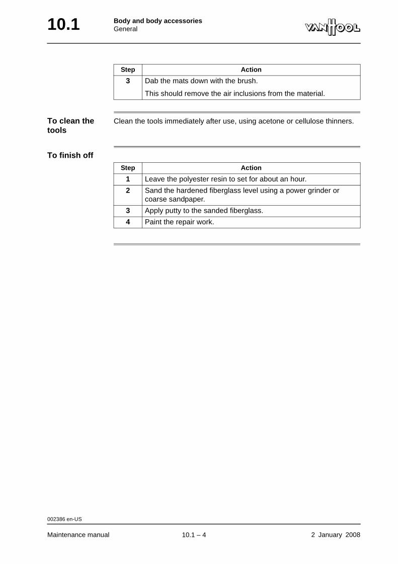
10.1 Body and body accessoriesGeneral
To clean the tools
Clean the tools immediately after use, using acetone or cellulose thinners.
To finish off
3 Dab the mats down with the brush.
This should remove the air inclusions from the material.
Step Action
Step Action
1 Leave the polyester resin to set for about an hour.
2 Sand the hardened fiberglass level using a power grinder or coarse sandpaper.
3 Apply putty to the sanded fiberglass.
4 Paint the repair work.
002386 en-US
Maintenance manual 2 January 2008
.
10.1 – 4
Body and body accessoriesGeneral 10.1
Vehicle exterior: lacquer care
CAUTION!When using commercial cleaning agents, preservative products and paint, always strictly follow the manufacturer's instructions.
General washing instructions
• Wash the body with ample, preferably softened, water.
• Use non-aggressive, non-abrasive cleaning agents only, always in liquid form and in the amount indicated by the manufacturer.
• Always wash the vehicle with clean water first. During this preliminary washing sand is soaked off and removed so that it cannot scratch the lacquer during the actual washing process. Use a soft brush to which no pressure is being applied.
• For hand-washing use a sponge or a car wash brush with soft bristles set in a holder made of rubber or soft synthetic material.
• Before removing dried-on insects, first soak them off with a special retail product.
• After washing, rinse the body thoroughly with soft water. Soap residues can damage the lacquer.
• After rinsing, you can dry the body with a soft chamois cloth.
To wash with brush machines
• When washing vehicles with exterior mirrors that have been attached by means of dovetail connectors, remove the mirrors before washing.
• Many automatic car wash systems use sensors to open doors automati-cally or to activate machines. The parts of these sensors that touch the body have to be made of soft rubber or soft synthetic material.
• Take care that the vehicle goes through the car wash system positioned right in the center.
• The washing brushes must be adjusted correctly, so that they can reach everywhere without causing any wear. They must not touch the vehicle underside.
• The brushes should never work on one location of the body for too long; the vehicle has to move along the brushes without stopping, or vice versa.
• The sprinklers of the car wash system have to pray with their normal flow rate. Therefore, not too many sprinkler holes should be clogged.
000763 en-US
2 January 2008 Maintenance manual
continued on next page.
10.1 – 5
10.1 Body and body accessoriesGeneral
To wash with high-pressure cleaners
• High-pressure cleaners do remove dirt, but not the greasy film on the body. A brush or sponge is still needed to remove this film.
• Do not set the machine too hot; 160 °F is the maximum.
• Pressure on the jet pipe must not exceed 580 psi.
• Keep the jet pipe head at least 12 in away from the lacquer and not on the same spot for too long. Otherwise, if the water is hot, you run the risk that the dirt is driven into the lacquer.
To remove road tar
• Remove tar spots with a special product or with denaturated alcohol. Apply the cleaning agent with a soft cloth and carefully rub the cloth over the spot. Do not press too hard. Otherwise the sand grains that are stuck in the tar will scratch the lacquer.
• After the tar has been removed, wash and rinse the treated area.
Minor repairs to finish
• Repairs can be made with any type of good quality lacquer, without risking harm to the existing lacquer.
• First thoroughly clean the area that is to be treated (remove dirt and grease).
• Carefully sand the area that is to be repaired, so that the new lacquer can adhere well to the existing layer.
• Use a rust-preventive primer.
• Closely follow the paint manufacturer's instructions.
To wax finish • After winter, it is a good idea to wax the vehicle with a liquid, non-abrasive polish. The body has to be absolutely clean and dry, before doing so.
• To give weathered or spotted lacquer its original shine a slightly grinding polish can be used. To prevent the lacquer from getting too thin, rub evenly and not on the same spot for too long. After cleaner treatment, apply a preservative layer of wax immediately.
000763 en-US
Maintenance manual 2 January 2008
.
10.1 – 6
Body and body accessoriesGeneral 10.1
Vehicle exterior: underbody care
To be carried out when?
Once a year, after winter, the vehicle underbody has to be cleaned and inspected.
Procedure
Step Action
1
CAUTION!Do not spray the following spots with a high-pressure cleaner: greasing points, bearings, shaft seals, universal joints, protective covers of steering system. Penetrating water may cause damage due to corrosion.
Spray vehicle underbody with cold water to remove all mud and salt.
NOTE: The water must not contain any detergents or petroleum derivatives, because they can damage the rust-preventive layer. Pressure on jet pipe must not exceed 725 psi.
2 Check rust-preventive layer for discontinuities.
• No discontinuities: underbody is all right.
• Discontinuities: go to step 3.
3 Allow underbody to fully dry.
4
CAUTION!If you have to spray rust-preventing liquid near compressed-air devices, first cover openings or mufflers of these devices.
Spray the areas that show discontinuities with proper anti-rust product for vehicle underbodies, such as Diffutherm UBC WAX 70 Metallic (Van Hool order number 660827810).
000764 en-US
2 January 2008 Maintenance manual
.
10.1 – 7
10.1 Body and body accessoriesGeneral
Vehicle exterior: to clean chrome or anodized aluminum
Chrome • Wash the chrome with soapy water, followed by a thorough rinsing.
• You can polish slightly neglected chrome with chrome polish.
• Protect chrome parts in the winter months by waxing them with special protective wax available from retail sale.
Anodized aluminum
• Clean anodized aluminum parts with neutral, non-abrasive synthetic products (definitely not chrome polish or agents containing soda, ammonium, chlorine or phosphoric acid).
• Stubborn spots should not be treated with steel wool, or else the extremely thin protective layer will be worn away and the aluminum will start oxi-dizing. If necessary, use a dish washing scrub pad made of polyamide wool, such as Scotch Brite (from 3M).
• Thoroughly rinse aluminum afterwards to remove any residue of the cleaning product.
000766 en-US
Maintenance manual 2 January 2008
.
10.1 – 8
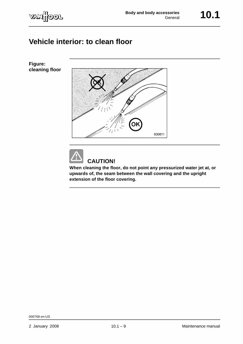
Body and body accessoriesGeneral 10.1
Vehicle interior: to clean floor
Figure: cleaning floor
CAUTION!When cleaning the floor, do not point any pressurized water jet at, or upwards of, the seam between the wall covering and the upright extension of the floor covering.
000768 en-US
2 January 2008 Maintenance manual
.
10.1 – 9
10.1 Body and body accessoriesGeneral
Vehicle interior: to clean moquette seat upholstery
To vacuum Clean upholstery weekly with a vacuum cleaner.
To wash Moquette upholstery can be washed without any risk using a solution of neutral soap in cold water.
To rejuvenate The moquette can be "rejuvenated" by steaming it. Lay a wet cloth over the seat upholstery and run a hot iron over it. The steam goes into the fibers and perks them up.
Step Action
1 Apply soapy water in small amounts using a sponge or soft brush. Rub in the same direction as the fibers of the fabric go.
2 Remove soap with a soft, clean cloth or sponge.
3 Repeatedly rub the treated area with a dry cloth.
4 Rub moquette that is still damp with a fairly hard brush.
5 Once the seat upholstery is dry, brush it once again, brushing in the same direction as the fibers.
000770 en-US
Maintenance manual 2 January 2008
.
10.1 – 10
Body and body accessoriesGeneral 10.1
Vehicle interior: to wash crepe head-rest covers
Guidelines • The cloths have to be washed without softener. Otherwise the crepe becomes unattractive.
• Use detergent "for fine washables", in water of about 86 °F. Rinse well in clean water and air-dry (do not wring out). Do not use any bleach.
000772 en-US
2 January 2008 Maintenance manual
.
10.1 – 11
10.1 Body and body accessoriesGeneral
Vehicle interior: to remove stains from fabric upholstery
Guidelines • Clean stains as quickly as possible, before they dry or oxidate; afterwards, it is much more difficult to remove them.
• Use a retail stain remover suited to the nature of the stain and that is harmless to the fabric to be cleaned (read the packaging). Simple household cleaners can also do a good job. Consult a stain-removal guide to see which cleaner is the best suited to which kind of stain.
• If the nature of the stain is unknown, first treat it with a solution of water and detergent. If the stain does not go away, use a dry-cleaning chemical once you have allowed to fabric to dry completely.
• Only use white cloths or kitchen paper to apply stain-removal agents.
• Fresh coffee or chocolate stains are not difficult to remove with detergent in lukewarm water. But once they have dried, there is not much you can do about these stains.
• Felt tip marker can only be removed with alcohol, felt pen marks with trichlorethylene, and nail polish with acetone.
• The best way to remove chewing gum is to first freeze it with a spray product and then smash it and scrape it off.
• Always try chemical stain removers out on an area that is not or hardly visible first, to make sure it does not cause any discoloration or damage.
• When using chemical stain removers, ventilate the vehicle interior as well as possible.
000771 en-US
Maintenance manual 2 January 2008
.
10.1 – 12
Body and body accessoriesGeneral 10.1
Vehicle interior: to clean leatherette
Guidelines • Occasionally wipe the leatherette with lukewarm, soapy water and rinse with water to which has been added a little vinegar.
• Problematic stains can be removed with denaturated alcohol. Still, before treating large spots, it is advisable to do a test on a piece that is not so visible, so as to make sure no discoloration occurs.
• Keep the leatherette supple by treating it occasionally with a mixture of 0.8 gallons of water, 0.08 gallons of milk and a handful of kitchen salt. Use a sponge to apply the mixture. Do not rinse, dry with a chamois cloth only. Rinse and wring out the chamois cloth as you go.
000769 en-US
2 January 2008 Maintenance manual
.
10.1 – 13
10.1 Body and body accessoriesGeneral
Vehicle interior: to clean ABS plastic parts
WARNING!Do not use polish on steering wheel and ABS seats, or they will become too slippery.
CAUTION!Solvents such as white spirit, paint thinner, trichlorethylene or cleaning spirit damage ABS plastic.
Guidelines • Sponge the ABS plastic clean with warm, soapy water. A soft brush may be used with light pressure to remove stubborn spots.
• To renew the original shine of ABS parts, use a special retail product.
000773 en-US
Maintenance manual 2 January 2008
.
10.1 – 14

Body and body accessoriesGeneral 10.1
Vehicle interior: to clean Plexiglas panels
CAUTION!Solvents such as white spirit, thinner, trichlorethylene or cleaning spirit damage Plexiglas.
Guidelines • Never shine Plexiglas, when it is dry.
• Wash the panel thoroughly and dry it with an absolutely clean chamois cloth. After washing, apply anti-static polish.
• You can polish out small scratches with a fine polish sold retail for the purpose.
000774 en-US
2 January 2008 Maintenance manual
.
10.1 – 15

10.1 Body and body accessoriesGeneral
This page has been intentionally left blank.
000774 en-US
Maintenance manual 2 January 200810.1 – 16
Body and body accessoriesExternal lighting and signalling devices 10.2
Chapter 2: External lighting and signalling devices
Overview
Introduction This chapter deals with the exterior lighting and signalling devices.
Number of pages
10
Chapter publi-cation date
2 January 2008
Contents
Topic See page
To adjust headlamps 10.2-2
Exterior lighting lamp list 10.2-3
To replace headlamp bulb 10.2-5
To replace bulb of rear lamp cluster 10.2-9
2 January 2008 Maintenance manual
.
10.2 – 1
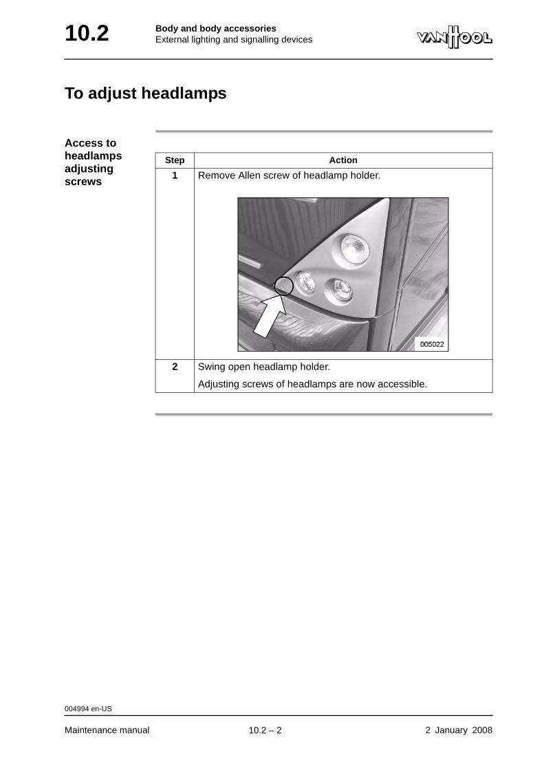
10.2 Body and body accessoriesExternal lighting and signalling devices
To adjust headlamps
Access to headlamps adjusting screws
Step Action
1 Remove Allen screw of headlamp holder.
2 Swing open headlamp holder.
Adjusting screws of headlamps are now accessible.
004994 en-US
Maintenance manual 2 January 2008
.
10.2 – 2
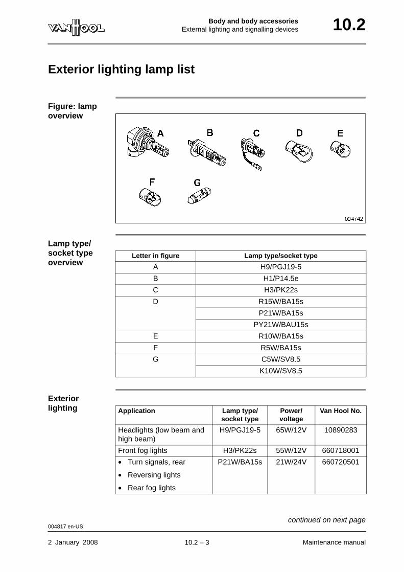
Body and body accessoriesExternal lighting and signalling devices 10.2
Exterior lighting lamp list
Figure: lamp overview
Lamp type/socket type overview
Exterior lighting
Letter in figure Lamp type/socket type
A H9/PGJ19-5
B H1/P14.5e
C H3/PK22s
D R15W/BA15s
P21W/BA15s
PY21W/BAU15s
E R10W/BA15s
F R5W/BA15s
G C5W/SV8.5
K10W/SV8.5
Application Lamp type/socket type
Power/voltage
Van Hool No.
Headlights (low beam and high beam)
H9/PGJ19-5 65W/12V 10890283
Front fog lights H3/PK22s 55W/12V 660718001
• Turn signals, rear
• Reversing lights
• Rear fog lights
P21W/BA15s 21W/24V 660720501
004817 en-US
2 January 2008 Maintenance manual
continued on next page.
10.2 – 3
10.2 Body and body accessoriesExternal lighting and signalling devices
Turn signals, front PY21W/BAU15s
21W/24V 10737576a
• Stop lights
• Rear position lights
Sealed unit with LEDs 10985545
Turn signals, left and right Sealed unit with LEDs 10898474
“Cornering lamps” R15W/BA15s 15W/24V 660720400
License plate lighting C5W/SV8.5 5W/24V 660725000
Stop light above engine compartment
Sealed unit with LEDs 10996977
• “Identification lamps”
• “Clearance lamps”
• “Side marker lamps”
Sealed unit with LEDs 10757391 (red)
10757389 (orange)
a. Orange bulb
Application Lamp type/socket type
Power/voltage
Van Hool No.
004817 en-US
Maintenance manual 2 January 2008
.
10.2 – 4
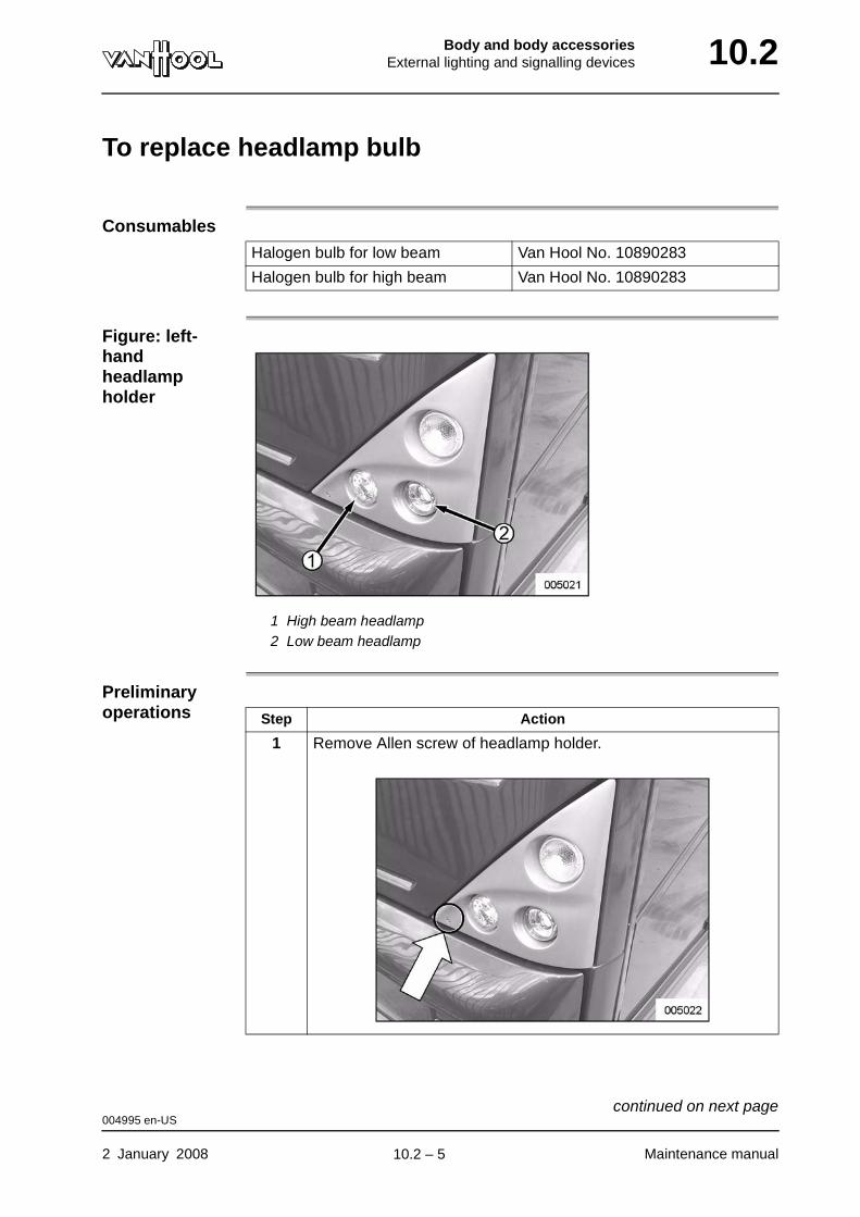
Body and body accessoriesExternal lighting and signalling devices 10.2
To replace headlamp bulb
Consumables
Figure: left-hand headlamp holder
1 High beam headlamp2 Low beam headlamp
Preliminary operations
Halogen bulb for low beam Van Hool No. 10890283
Halogen bulb for high beam Van Hool No. 10890283
Step Action
1 Remove Allen screw of headlamp holder.
004995 en-US
2 January 2008 Maintenance manual
continued on next page.
10.2 – 5
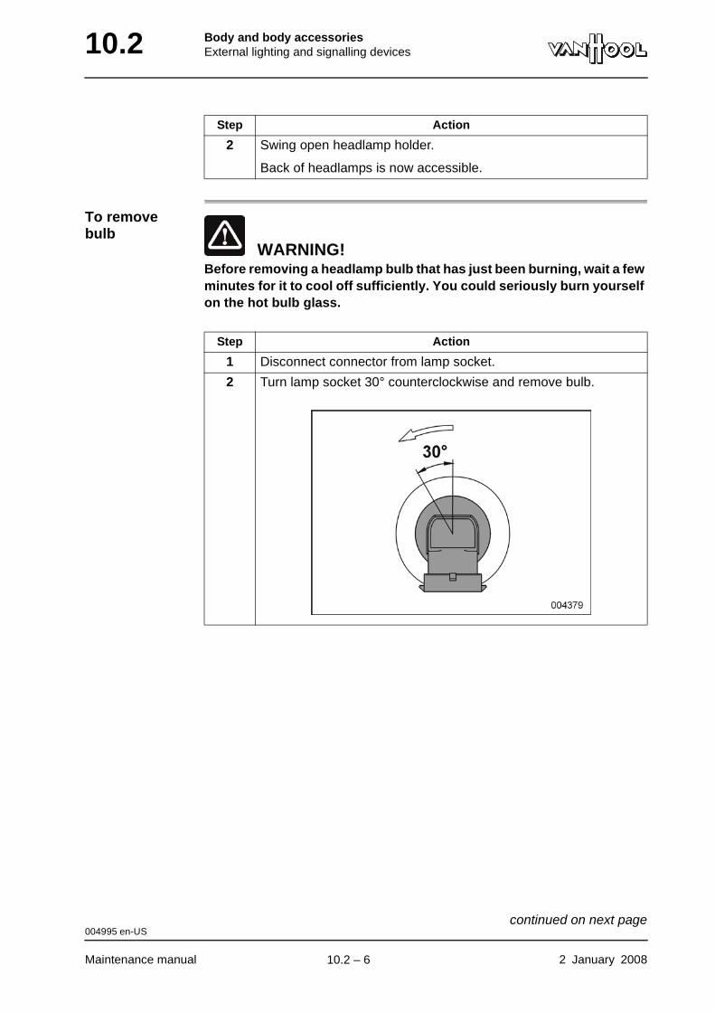
10.2 Body and body accessoriesExternal lighting and signalling devices
To remove bulb
WARNING!Before removing a headlamp bulb that has just been burning, wait a few minutes for it to cool off sufficiently. You could seriously burn yourself on the hot bulb glass.
2 Swing open headlamp holder.
Back of headlamps is now accessible.
Step Action
Step Action
1 Disconnect connector from lamp socket.
2 Turn lamp socket 30° counterclockwise and remove bulb.
004995 en-US
Maintenance manual 2 January 2008
continued on next page.
10.2 – 6
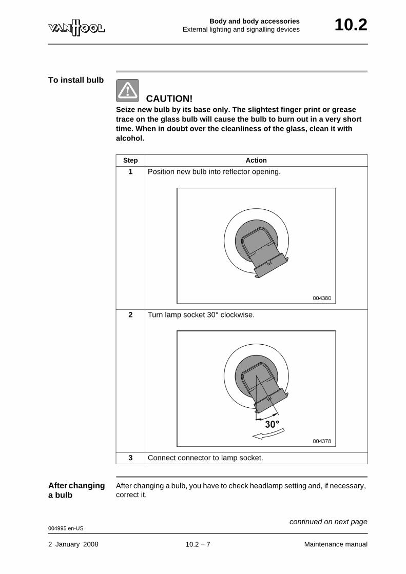
Body and body accessoriesExternal lighting and signalling devices 10.2
To install bulb
CAUTION!Seize new bulb by its base only. The slightest finger print or grease trace on the glass bulb will cause the bulb to burn out in a very short time. When in doubt over the cleanliness of the glass, clean it with alcohol.
After changing a bulb
After changing a bulb, you have to check headlamp setting and, if necessary, correct it.
Step Action
1 Position new bulb into reflector opening.
2 Turn lamp socket 30° clockwise.
3 Connect connector to lamp socket.
004995 en-US
2 January 2008 Maintenance manual
continued on next page.
10.2 – 7
10.2 Body and body accessoriesExternal lighting and signalling devices
004995 en-US
Maintenance manual 2 January 2008
.
10.2 – 8
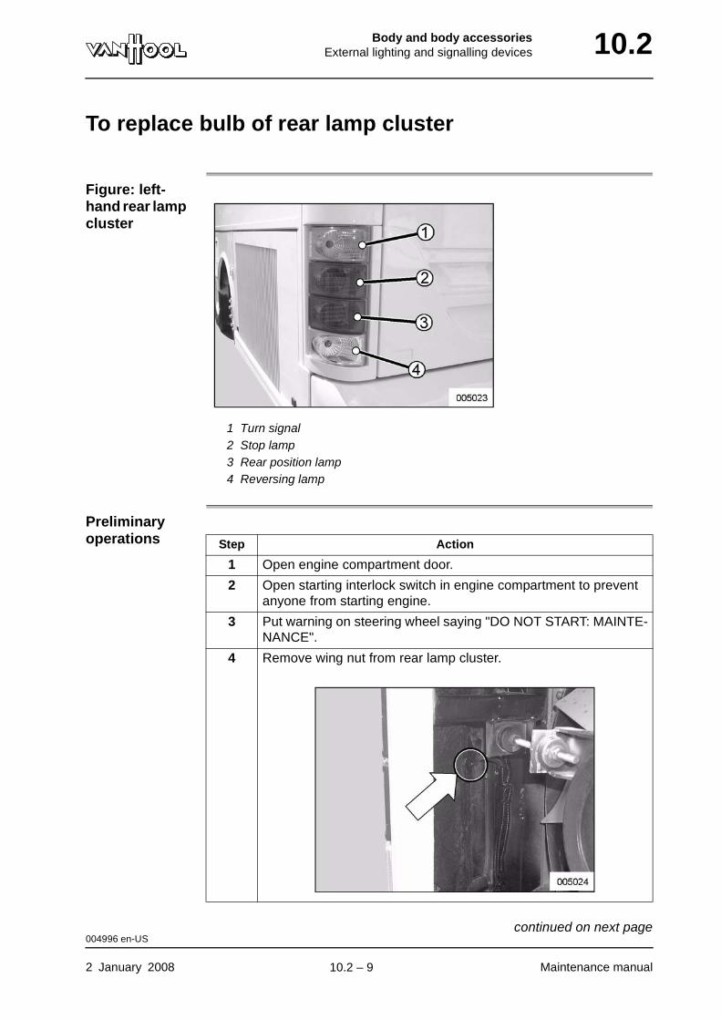
Body and body accessoriesExternal lighting and signalling devices 10.2
To replace bulb of rear lamp cluster
Figure: left-hand rear lamp cluster
1 Turn signal2 Stop lamp3 Rear position lamp4 Reversing lamp
Preliminary operations Step Action
1 Open engine compartment door.
2 Open starting interlock switch in engine compartment to prevent anyone from starting engine.
3 Put warning on steering wheel saying "DO NOT START: MAINTE-NANCE".
4 Remove wing nut from rear lamp cluster.
004996 en-US
2 January 2008 Maintenance manual
continued on next page.
10.2 – 9
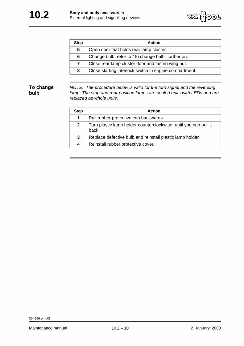
10.2 Body and body accessoriesExternal lighting and signalling devices
To change bulb
NOTE: The procedure below is valid for the turn signal and the reversing lamp. The stop and rear position lamps are sealed units with LEDs and are replaced as whole units.
5 Open door that holds rear lamp cluster.
6 Change bulb, refer to "To change bulb" further on.
7 Close rear lamp cluster door and fasten wing nut.
8 Close starting interlock switch in engine compartment.
Step Action
Step Action
1 Pull rubber protective cap backwards.
2 Turn plastic lamp holder counterclockwise, until you can pull it back.
3 Replace defective bulb and reinstall plastic lamp holder.
4 Reinstall rubber protective cover.
004996 en-US
Maintenance manual 2 January 2008
.
10.2 – 10
Body and body accessoriesInterior lighting equipment 10.6
Chapter 6: Interior lighting equipment
Overview
Introduction This chapter deals with the interior lighting equipment.
Number of pages
4
Chapter publi-cation date
2 January 2008
Contents
Topic See page
Interior lighting lamp list 10.6-2
"LIGHT" plug in main junction box 10.6-4
2 January 2008 Maintenance manual
.
10.6 – 1
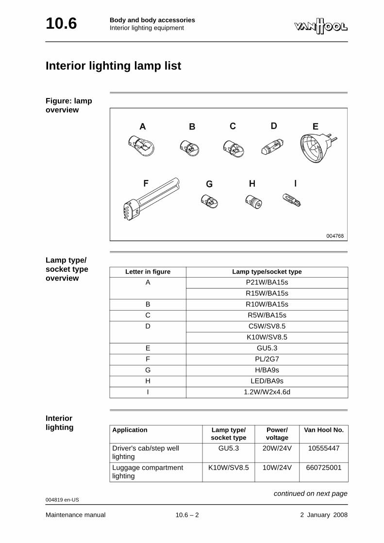
10.6 Body and body accessoriesInterior lighting equipment
Interior lighting lamp list
Figure: lamp overview
Lamp type/socket type overview
Interior lighting
Letter in figure Lamp type/socket type
A P21W/BA15s
R15W/BA15s
B R10W/BA15s
C R5W/BA15s
D C5W/SV8.5
K10W/SV8.5
E GU5.3
F PL/2G7
G H/BA9s
H LED/BA9s
I 1.2W/W2x4.6d
Application Lamp type/socket type
Power/voltage
Van Hool No.
Driver's cab/step well lighting
GU5.3 20W/24V 10555447
Luggage compartment lighting
K10W/SV8.5 10W/24V 660725001
004819 en-US
Maintenance manual 2 January 2008
continued on next page.
10.6 – 2
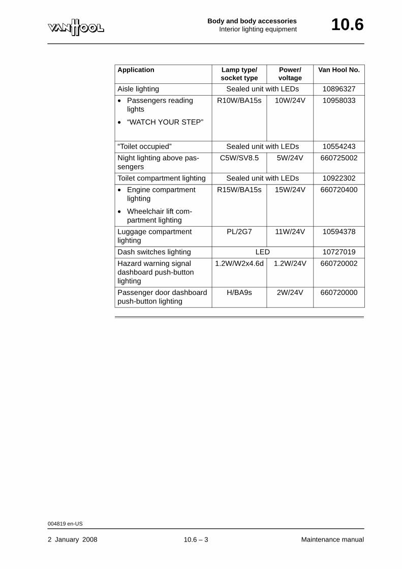
Body and body accessoriesInterior lighting equipment 10.6
Aisle lighting Sealed unit with LEDs 10896327
• Passengers reading lights
• “WATCH YOUR STEP”
R10W/BA15s 10W/24V 10958033
“Toilet occupied” Sealed unit with LEDs 10554243
Night lighting above pas-sengers
C5W/SV8.5 5W/24V 660725002
Toilet compartment lighting Sealed unit with LEDs 10922302
• Engine compartment lighting
• Wheelchair lift com-partment lighting
R15W/BA15s 15W/24V 660720400
Luggage compartment lighting
PL/2G7 11W/24V 10594378
Dash switches lighting LED 10727019
Hazard warning signal dashboard push-button lighting
1.2W/W2x4.6d 1.2W/24V 660720002
Passenger door dashboard push-button lighting
H/BA9s 2W/24V 660720000
Application Lamp type/socket type
Power/voltage
Van Hool No.
004819 en-US
2 January 2008 Maintenance manual
.
10.6 – 3
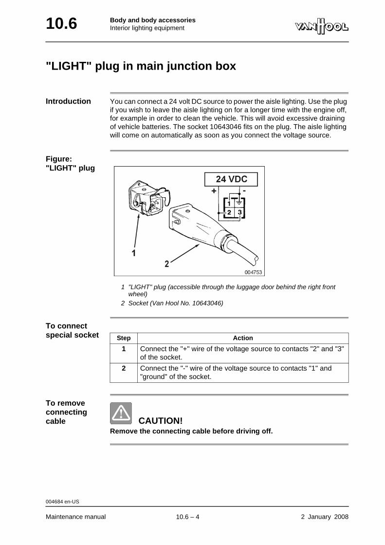
10.6 Body and body accessoriesInterior lighting equipment
"LIGHT" plug in main junction box
Introduction You can connect a 24 volt DC source to power the aisle lighting. Use the plug if you wish to leave the aisle lighting on for a longer time with the engine off, for example in order to clean the vehicle. This will avoid excessive draining of vehicle batteries. The socket 10643046 fits on the plug. The aisle lighting will come on automatically as soon as you connect the voltage source.
Figure: "LIGHT" plug
1 "LIGHT" plug (accessible through the luggage door behind the right front wheel)
2 Socket (Van Hool No. 10643046)
To connect special socket
To remove connecting cable CAUTION!
Remove the connecting cable before driving off.
Step Action
1 Connect the "+" wire of the voltage source to contacts "2" and "3" of the socket.
2 Connect the "-" wire of the voltage source to contacts "1" and "ground" of the socket.
004684 en-US
Maintenance manual 2 January 2008
.
10.6 – 4
Body and body accessoriesEntrance and exit doors 10.62
Chapter 62: Entrance and exit doors
Overview
Introduction This chapter deals with the entrance and exit doors.
Number of pages
16
Chapter publi-cation date
2 January 2008
Contents
Topic See page
Safety precautions for passenger doors 10.62-2
Passenger door: schematic diagram 10.62-3
Passenger door: to check door safety systems and emer-gency valves
10.62-5
Passenger door: to lubricate locking wedges and cams 10.62-7
Passenger door: to lubricate door spindle 10.62-8
Passenger door: to check opening/closing time 10.62-9
Passenger door: to adjust opening/closing time 10.62-10
Passenger door: to set reversing-system switches 10.62-12
To preserve rubber door seals 10.62-15
2 January 2008 Maintenance manual
.
10.62 – 1
10.62 Body and body accessoriesEntrance and exit doors
Safety precautions for passenger doors
WARNING!After working on a passenger door, check the closing power of that door before putting the vehicle back into service.
Equipment condition
Air system charged to maximum operating pressure
Procedure
Step Action
1 Close the door from the dashboard.
2 From the interior, push firmly in the middle of the door.
The door should not open.
002534 en-US
Maintenance manual 2 January 2008
.
10.62 – 2

Body and body accessoriesEntrance and exit doors 10.62
Passenger door: schematic diagram
Figure: passenger door schematic diagram
Figure shows a closed, unlocked passenger door
1 Compressed-air supply2 4/2-way valve, manually operated3 Flow control valve4 4/2-way valve, electrically operated (V011)5 Flow control valve6 Door actuating cylinder7 Pressure switch (DK055)8 Reversing switch (MS028)9 Limit switch (MS033.2)
10 Switch (MS059) to open/close the door from the exterior11 Dashswitch (S091) to open/close the door from the interior12 Locking switch (MS057)B+ Voltage after batteries
Z Circuit breaker or fuse
004954 en-US
2 January 2008 Maintenance manual
continued on next page.
10.62 – 3
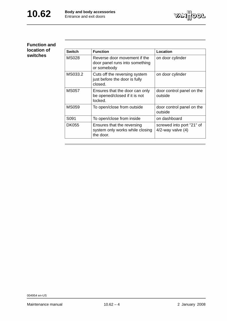
10.62 Body and body accessoriesEntrance and exit doors
Function and location of switches
Switch Function Location
MS028 Reverse door movement if the door panel runs into something or somebody
on door cylinder
MS033.2 Cuts off the reversing system just before the door is fully closed.
on door cylinder
MS057 Ensures that the door can only be opened/closed if it is not locked.
door control panel on the outside
MS059 To open/close from outside door control panel on the outside
S091 To open/close from inside on dashboard
DK055 Ensures that the reversing system only works while closing the door.
screwed into port "21" of 4/2-way valve (4)
004954 en-US
Maintenance manual 2 January 2008
.
10.62 – 4
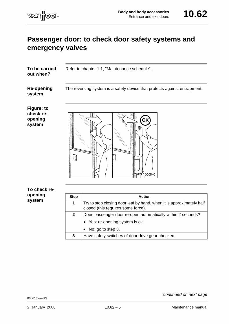
Body and body accessoriesEntrance and exit doors 10.62
Passenger door: to check door safety systems and emergency valves
To be carried out when?
Refer to chapter 1.1, "Maintenance schedule".
Re-opening system
The reversing system is a safety device that protects against entrapment.
Figure: to check re-opening system
To check re-opening system
Step Action
1 Try to stop closing door leaf by hand, when it is approximately half closed (this requires some force).
2 Does passenger door re-open automatically within 2 seconds?
• Yes: re-opening system is ok.
• No: go to step 3.
3 Have safety switches of door drive gear checked.
000616 en-US
2 January 2008 Maintenance manual
continued on next page.
10.62 – 5
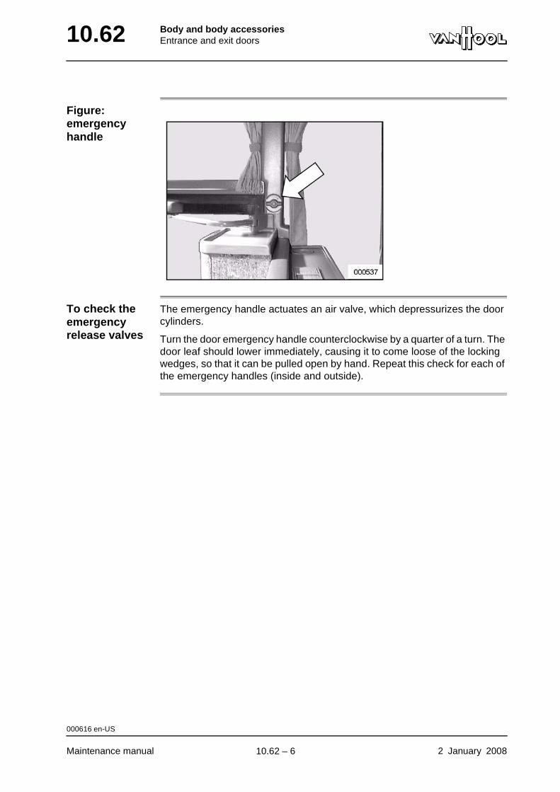
10.62 Body and body accessoriesEntrance and exit doors
Figure: emergency handle
To check the emergency release valves
The emergency handle actuates an air valve, which depressurizes the door cylinders.
Turn the door emergency handle counterclockwise by a quarter of a turn. The door leaf should lower immediately, causing it to come loose of the locking wedges, so that it can be pulled open by hand. Repeat this check for each of the emergency handles (inside and outside).
000616 en-US
Maintenance manual 2 January 2008
.
10.62 – 6
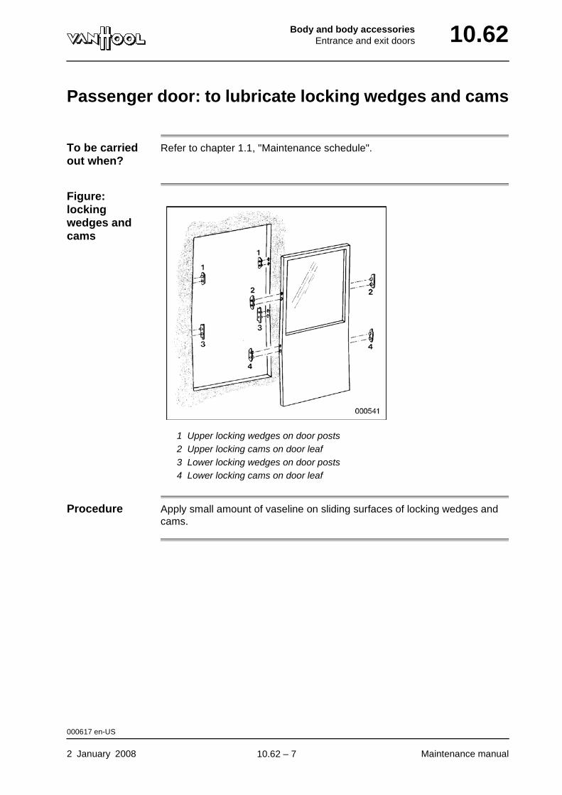
Body and body accessoriesEntrance and exit doors 10.62
Passenger door: to lubricate locking wedges and cams
To be carried out when?
Refer to chapter 1.1, "Maintenance schedule".
Figure: locking wedges and cams
1 Upper locking wedges on door posts2 Upper locking cams on door leaf3 Lower locking wedges on door posts4 Lower locking cams on door leaf
Procedure Apply small amount of vaseline on sliding surfaces of locking wedges and cams.
000617 en-US
2 January 2008 Maintenance manual
.
10.62 – 7
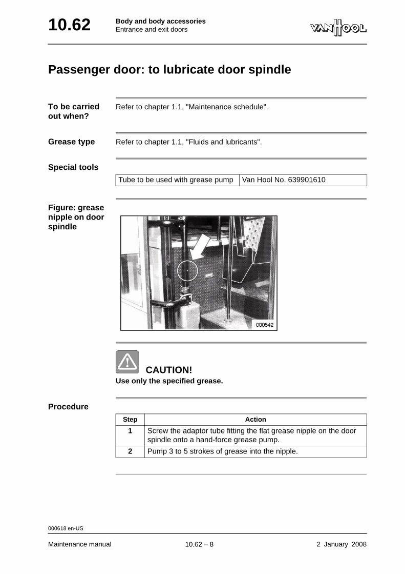
10.62 Body and body accessoriesEntrance and exit doors
Passenger door: to lubricate door spindle
To be carried out when?
Refer to chapter 1.1, "Maintenance schedule".
Grease type Refer to chapter 1.1, "Fluids and lubricants".
Special tools
Figure: grease nipple on door spindle
CAUTION!Use only the specified grease.
Procedure
Tube to be used with grease pump Van Hool No. 639901610
Step Action
1 Screw the adaptor tube fitting the flat grease nipple on the door spindle onto a hand-force grease pump.
2 Pump 3 to 5 strokes of grease into the nipple.
000618 en-US
Maintenance manual 2 January 2008
.
10.62 – 8
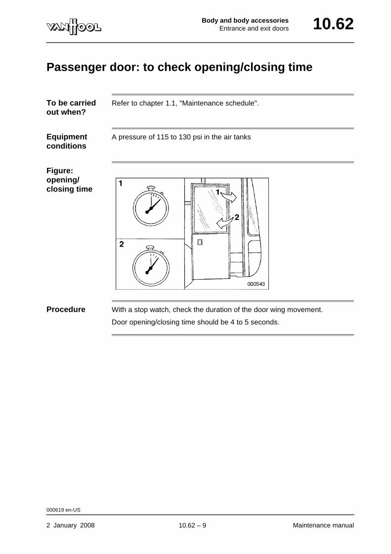
Body and body accessoriesEntrance and exit doors 10.62
Passenger door: to check opening/closing time
To be carried out when?
Refer to chapter 1.1, "Maintenance schedule".
Equipment conditions
A pressure of 115 to 130 psi in the air tanks
Figure: opening/closing time
Procedure With a stop watch, check the duration of the door wing movement.
Door opening/closing time should be 4 to 5 seconds.
000619 en-US
2 January 2008 Maintenance manual
.
10.62 – 9
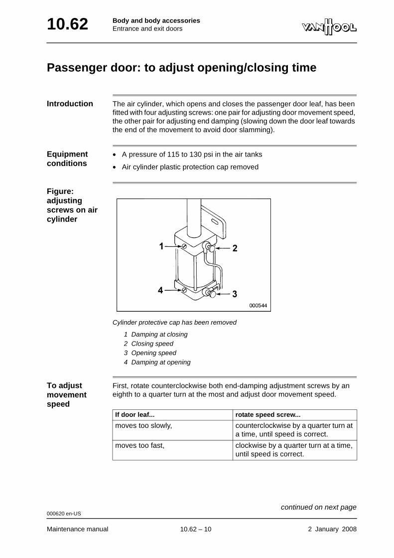
10.62 Body and body accessoriesEntrance and exit doors
Passenger door: to adjust opening/closing time
Introduction The air cylinder, which opens and closes the passenger door leaf, has been fitted with four adjusting screws: one pair for adjusting door movement speed, the other pair for adjusting end damping (slowing down the door leaf towards the end of the movement to avoid door slamming).
Equipment conditions
• A pressure of 115 to 130 psi in the air tanks
• Air cylinder plastic protection cap removed
Figure: adjusting screws on air cylinder
Cylinder protective cap has been removed
1 Damping at closing2 Closing speed3 Opening speed4 Damping at opening
To adjust movement speed
First, rotate counterclockwise both end-damping adjustment screws by an eighth to a quarter turn at the most and adjust door movement speed.
If door leaf... rotate speed screw...
moves too slowly, counterclockwise by a quarter turn at a time, until speed is correct.
moves too fast, clockwise by a quarter turn at a time, until speed is correct.
000620 en-US
Maintenance manual 2 January 2008
continued on next page.
10.62 – 10
Body and body accessoriesEntrance and exit doors 10.62
To adjust damping To... turn adjusting screw...
increase damping clockwise.
decrease damping counterclockwise.
000620 en-US
2 January 2008 Maintenance manual
.
10.62 – 11
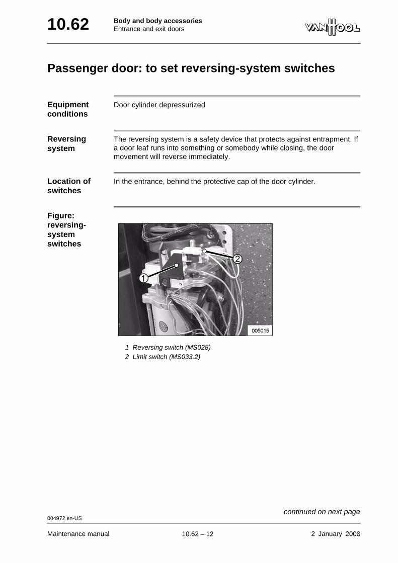
10.62 Body and body accessoriesEntrance and exit doors
Passenger door: to set reversing-system switches
Equipment conditions
Door cylinder depressurized
Reversing system
The reversing system is a safety device that protects against entrapment. If a door leaf runs into something or somebody while closing, the door movement will reverse immediately.
Location of switches
In the entrance, behind the protective cap of the door cylinder.
Figure: reversing-system switches
1 Reversing switch (MS028)2 Limit switch (MS033.2)
004972 en-US
Maintenance manual 2 January 2008
continued on next page.
10.62 – 12
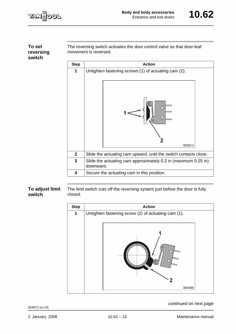
Body and body accessoriesEntrance and exit doors 10.62
To set reversing switch
The reversing switch activates the door control valve so that door-leaf movement is reversed.
To adjust limit switch
The limit switch cuts off the reversing system just before the door is fully closed.
Step Action
1 Untighten fastening screws (1) of actuating cam (2).
2 Slide the actuating cam upward, until the switch contacts close.
3 Slide the actuating cam approximately 0.2 in (maximum 0.25 in) downward.
4 Secure the actuating cam in this position.
Step Action
1 Untighten fastening screw (2) of actuating cam (1).
004972 en-US
2 January 2008 Maintenance manual
continued on next page.
10.62 – 13

10.62 Body and body accessoriesEntrance and exit doors
2 Close the door by pushing it by hand.
3 Turn the actuating cam, until the switch contacts open.
4 Secure the actuating cam in this position.
Step Action
004972 en-US
Maintenance manual 2 January 2008
.
10.62 – 14
Body and body accessoriesEntrance and exit doors 10.62
To preserve rubber door seals
To be carried out when?
Refer to chapter 1.1, "Maintenance schedule".
Procedure Rubber edge trims on door(s) harden less quickly if you treat them with sil-icone grease. Make sure you do not forget the inside of the rubber seals on the door leaf: the inside has to be able to slide smoothly along the posts, when the door leaf rises.
CAUTION!Do not use vaseline as it freezes in winter, and will tear the rubbers.
000615 en-US
2 January 2008 Maintenance manual
.
10.62 – 15

10.62 Body and body accessoriesEntrance and exit doors
This page has been intentionally left blank.
000615 en-US
Maintenance manual 2 January 200810.62 – 16

Part 11 - Control systems
Overview
Contents
Chapter See page
Chapter 1: Multiplex system 11.1-1
Chapter 2: ATC 11.2-1

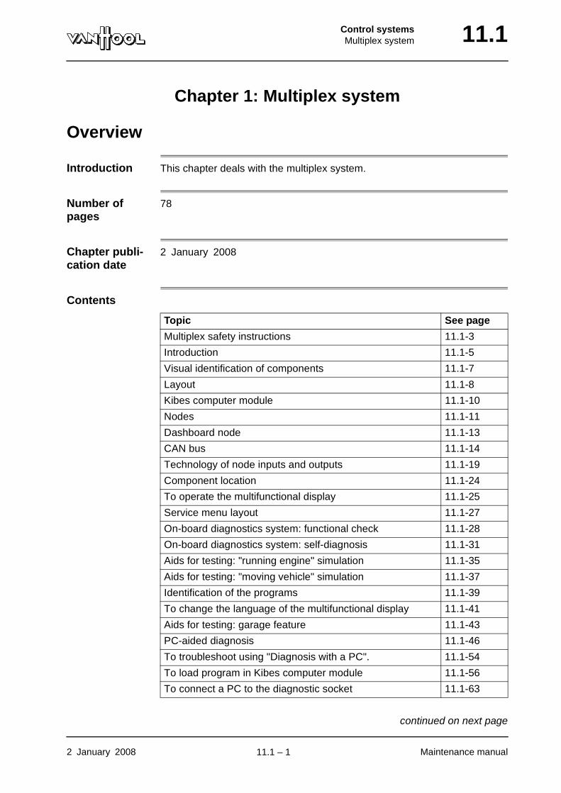
Control systemsMultiplex system 11.1
Chapter 1: Multiplex system
Overview
Introduction This chapter deals with the multiplex system.
Number of pages
78
Chapter publi-cation date
2 January 2008
Contents
Topic See page
Multiplex safety instructions 11.1-3
Introduction 11.1-5
Visual identification of components 11.1-7
Layout 11.1-8
Kibes computer module 11.1-10
Nodes 11.1-11
Dashboard node 11.1-13
CAN bus 11.1-14
Technology of node inputs and outputs 11.1-19
Component location 11.1-24
To operate the multifunctional display 11.1-25
Service menu layout 11.1-27
On-board diagnostics system: functional check 11.1-28
On-board diagnostics system: self-diagnosis 11.1-31
Aids for testing: "running engine" simulation 11.1-35
Aids for testing: "moving vehicle" simulation 11.1-37
Identification of the programs 11.1-39
To change the language of the multifunctional display 11.1-41
Aids for testing: garage feature 11.1-43
PC-aided diagnosis 11.1-46
To troubleshoot using "Diagnosis with a PC". 11.1-54
To load program in Kibes computer module 11.1-56
To connect a PC to the diagnostic socket 11.1-63
2 January 2008 Maintenance manual
continued on next page.
11.1 – 1
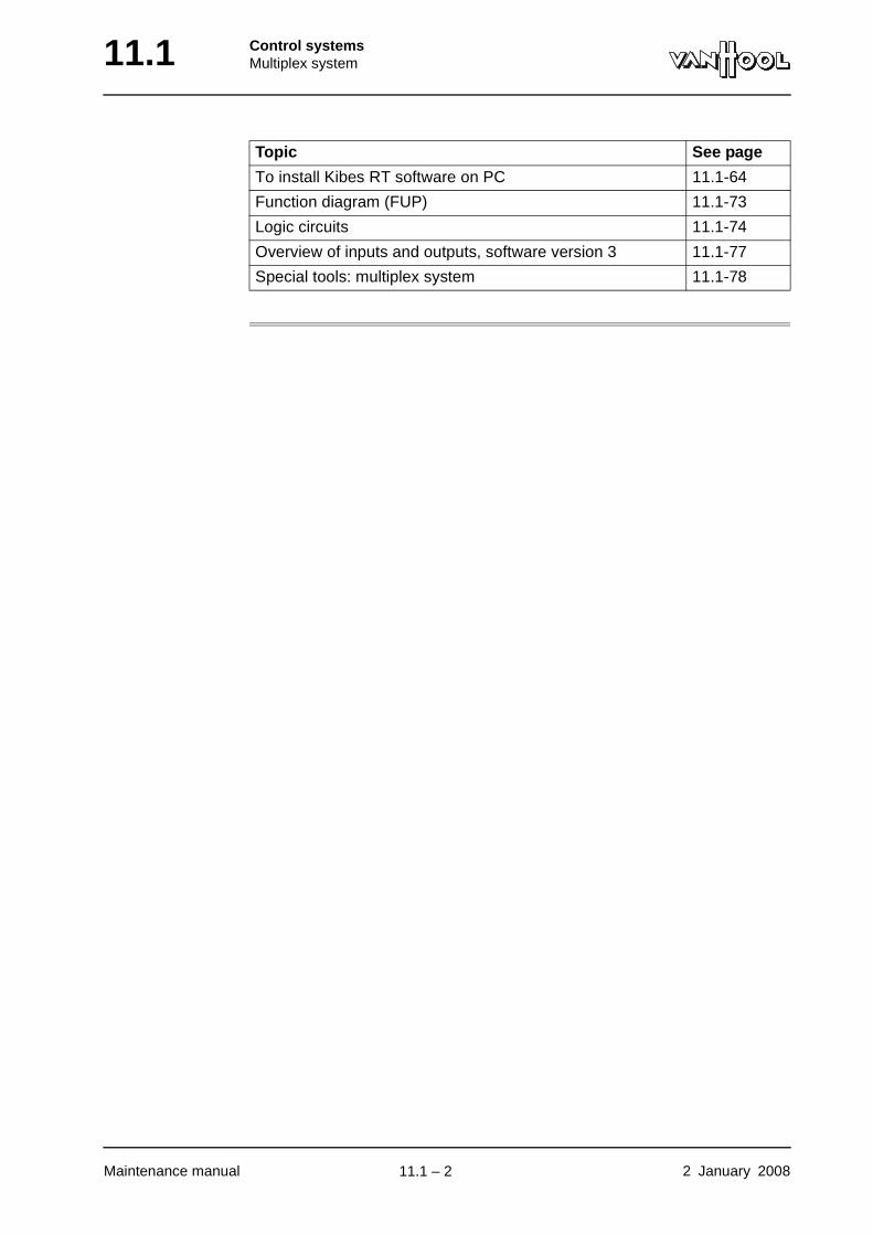
11.1 Control systemsMultiplex system
To install Kibes RT software on PC 11.1-64
Function diagram (FUP) 11.1-73
Logic circuits 11.1-74
Overview of inputs and outputs, software version 3 11.1-77
Special tools: multiplex system 11.1-78
Topic See page
Maintenance manual 2 January 2008
.
11.1 – 2
Control systemsMultiplex system 11.1
Multiplex safety instructions
WARNING!Before operating the multifunctional display to perform simulations or functional tests via the multiplex system, warn people working on the vehicle or about to do so that climate-control system fans and other devices may suddenly engage without the engine running.
WARNING!Never operate the multifunctional display while driving.
CAUTION!Before carrying out electrical welding on the vehicle, first turn off the battery isolating switch and subsequently remove the connectors from all electronic control units.
CAUTION!Only use a multimeter as a test device, not a test lamp.
CAUTION!Do not lengthen or shorten the CAN bus. Do not remove termination resistors.
CAUTION!The electronics are very sensitive. Incorrect connection leads to damage. Avoid reversing polarity connections.
003327 en-US
2 January 2008 Maintenance manual
continued on next page.
11.1 – 3
11.1 Control systemsMultiplex system
CAUTION!Repairs to the wiring must always be carried out in accordance with the principles of good workmanship. Take appropriate care when soldering and crimping.
003327 en-US
Maintenance manual 2 January 2008
.
11.1 – 4
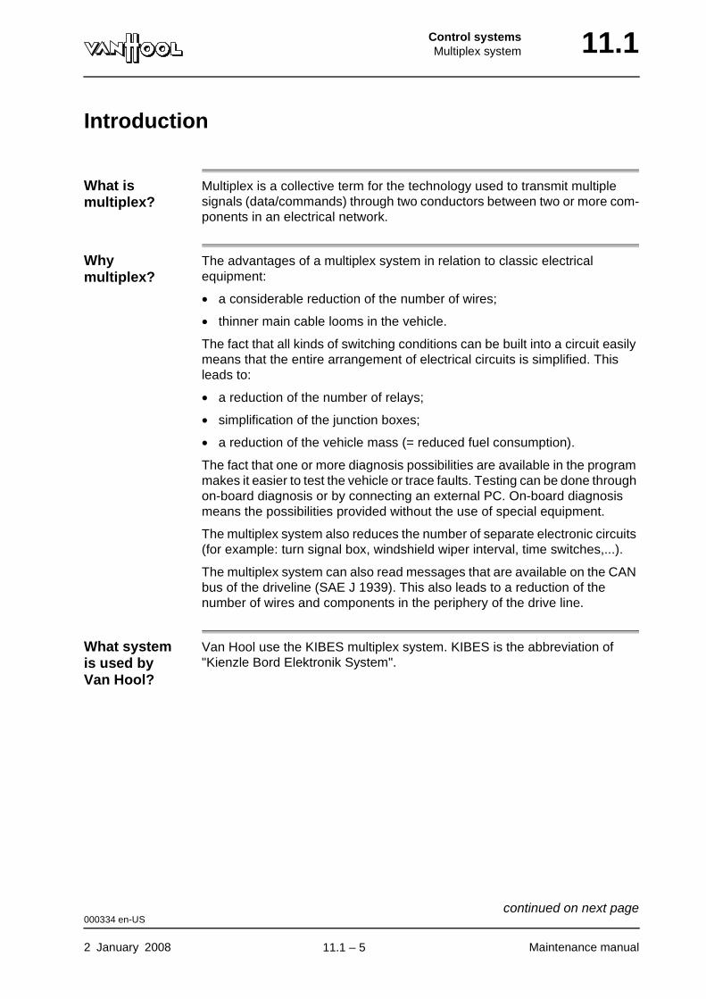
Control systemsMultiplex system 11.1
Introduction
What is multiplex?
Multiplex is a collective term for the technology used to transmit multiple signals (data/commands) through two conductors between two or more com-ponents in an electrical network.
Why multiplex?
The advantages of a multiplex system in relation to classic electrical equipment:
• a considerable reduction of the number of wires;
• thinner main cable looms in the vehicle.
The fact that all kinds of switching conditions can be built into a circuit easily means that the entire arrangement of electrical circuits is simplified. This leads to:
• a reduction of the number of relays;
• simplification of the junction boxes;
• a reduction of the vehicle mass (= reduced fuel consumption).
The fact that one or more diagnosis possibilities are available in the program makes it easier to test the vehicle or trace faults. Testing can be done through on-board diagnosis or by connecting an external PC. On-board diagnosis means the possibilities provided without the use of special equipment.
The multiplex system also reduces the number of separate electronic circuits (for example: turn signal box, windshield wiper interval, time switches,...).
The multiplex system can also read messages that are available on the CAN bus of the driveline (SAE J 1939). This also leads to a reduction of the number of wires and components in the periphery of the drive line.
What system is used by Van Hool?
Van Hool use the KIBES multiplex system. KIBES is the abbreviation of "Kienzle Bord Elektronik System".
000334 en-US
2 January 2008 Maintenance manual
continued on next page.
11.1 – 5
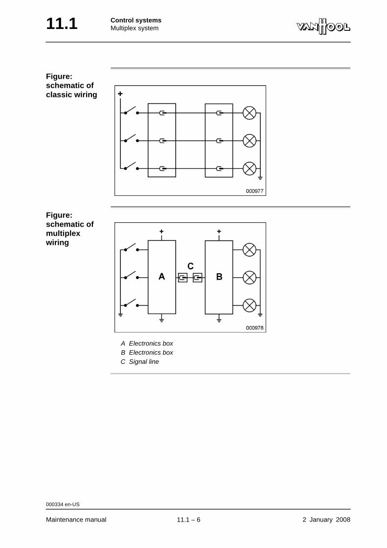
11.1 Control systemsMultiplex system
Figure: schematic of classic wiring
Figure: schematic of multiplex wiring
A Electronics boxB Electronics boxC Signal line
000334 en-US
Maintenance manual 2 January 2008
.
11.1 – 6
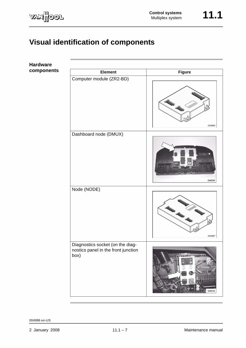
Control systemsMultiplex system 11.1
Visual identification of components
Hardware components Element Figure
Computer module (ZR2-BD)
Dashboard node (DMUX)
Node (NODE)
Diagnostics socket (on the diag-nostics panel in the front junction box)
004986 en-US
2 January 2008 Maintenance manual
.
11.1 – 7

11.1 Control systemsMultiplex system
Layout
Introduction The system is constructed with "hardware" components (= all equipment in the system). This "hardware" is controlled by the "software" (= program which enables the "hardware" to function as required).
Hardware components
The Kibes system consists of the following "hardware" components:
• a computer module (master) that contains the driver, in other words the programmable intelligence;
• a dashboard node (slave) that contains programmable information;
• a number of nodes (slaves) without programmable intelligence, just inputs and outputs;
• CAN-bus (interconnection between the elements of the multiplex system).
Figure: layout
1 Master2 Slave
002742 en-US
Maintenance manual 2 January 2008
continued on next page.
11.1 – 8
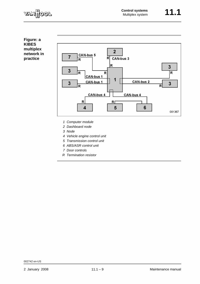
Control systemsMultiplex system 11.1
Figure: a KIBES multiplex network in practice
1 Computer module2 Dashboard node3 Node4 Vehicle engine control unit5 Transmission control unit6 ABS/ASR control unit7 Door controlsR Termination resistor
002742 en-US
2 January 2008 Maintenance manual
.
11.1 – 9
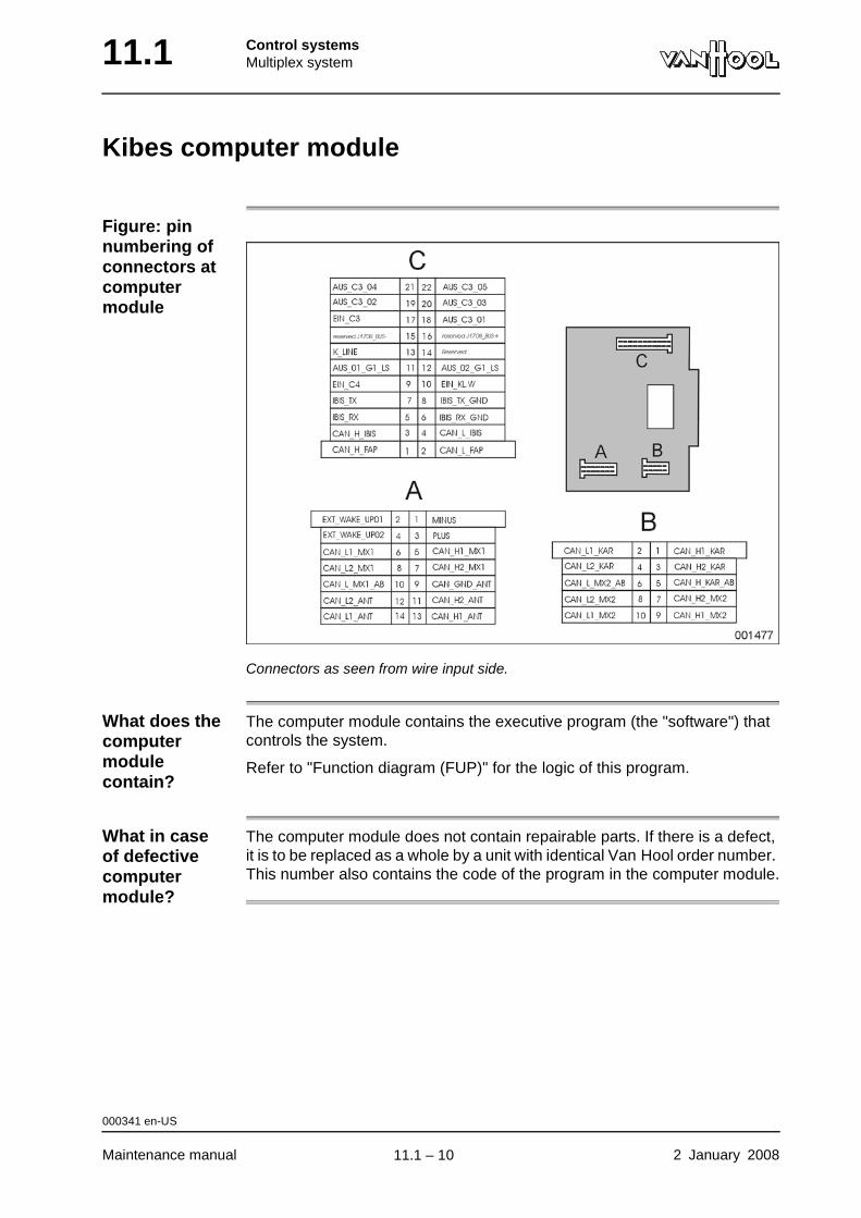
11.1 Control systemsMultiplex system
Kibes computer module
Figure: pin numbering of connectors at computer module
Connectors as seen from wire input side.
What does the computer module contain?
The computer module contains the executive program (the "software") that controls the system.
Refer to "Function diagram (FUP)" for the logic of this program.
What in case of defective computer module?
The computer module does not contain repairable parts. If there is a defect, it is to be replaced as a whole by a unit with identical Van Hool order number. This number also contains the code of the program in the computer module.
000341 en-US
Maintenance manual 2 January 2008
.
11.1 – 10
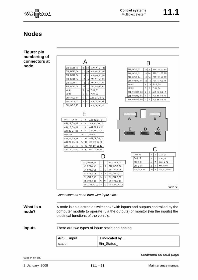
Control systemsMultiplex system 11.1
Nodes
Figure: pin numbering of connectors at node
Connectors as seen from wire input side.
What is a node?
A node is an electronic "switchbox" with inputs and outputs controlled by the computer module to operate (via the outputs) or monitor (via the inputs) the electrical functions of the vehicle.
Inputs There are two types of input: static and analog.
A(n) ... input is indicated by ...
static Ein_Status_
002844 en-US
2 January 2008 Maintenance manual
continued on next page.
11.1 – 11
11.1 Control systemsMultiplex system
Outputs The outputs are protected against overloads and short-circuits. An output is indicated with "Aus_".
The outputs are NOT protected against external application of a voltage to the output.
Power supply Each node is powered via five separate circuits, each fitted with a 15 A fuse. Each fuse protects a "group" of node outputs.
The internal electronics are fed via the fuse of "group 1" and/or "group 2".
Node locations
The nodes are located throughout the vehicle, close to the components to which they relate, thereby greatly reducing the amount of main cabling.
Are nodes inter-changeable?
All nodes are interchangeable, with the exception of the dashboard node. This is because the nodes do not contain any software on the one hand and the "addressing" takes place by means of an external wire combination in a connector on the other hand. Addressing ensures that the node recognizes the messages that are intended for it.
What in case of a defective node?
The nodes do not contain any user-repairable parts. A faulty unit must be replaced as a whole.
analog Ein_Analog_
A(n) ... input is indicated by ...
002844 en-US
Maintenance manual 2 January 2008
.
11.1 – 12
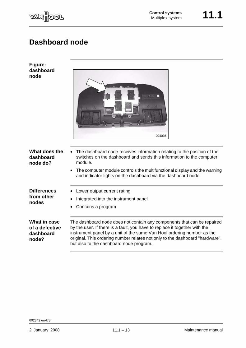
Control systemsMultiplex system 11.1
Dashboard node
Figure: dashboard node
What does the dashboard node do?
• The dashboard node receives information relating to the position of the switches on the dashboard and sends this information to the computer module.
• The computer module controls the multifunctional display and the warning and indicator lights on the dashboard via the dashboard node.
Differences from other nodes
• Lower output current rating
• Integrated into the instrument panel
• Contains a program
What in case of a defective dashboard node?
The dashboard node does not contain any components that can be repaired by the user. If there is a fault, you have to replace it together with the instrument panel by a unit of the same Van Hool ordering number as the original. This ordering number relates not only to the dashboard "hardware", but also to the dashboard node program.
002842 en-US
2 January 2008 Maintenance manual
.
11.1 – 13
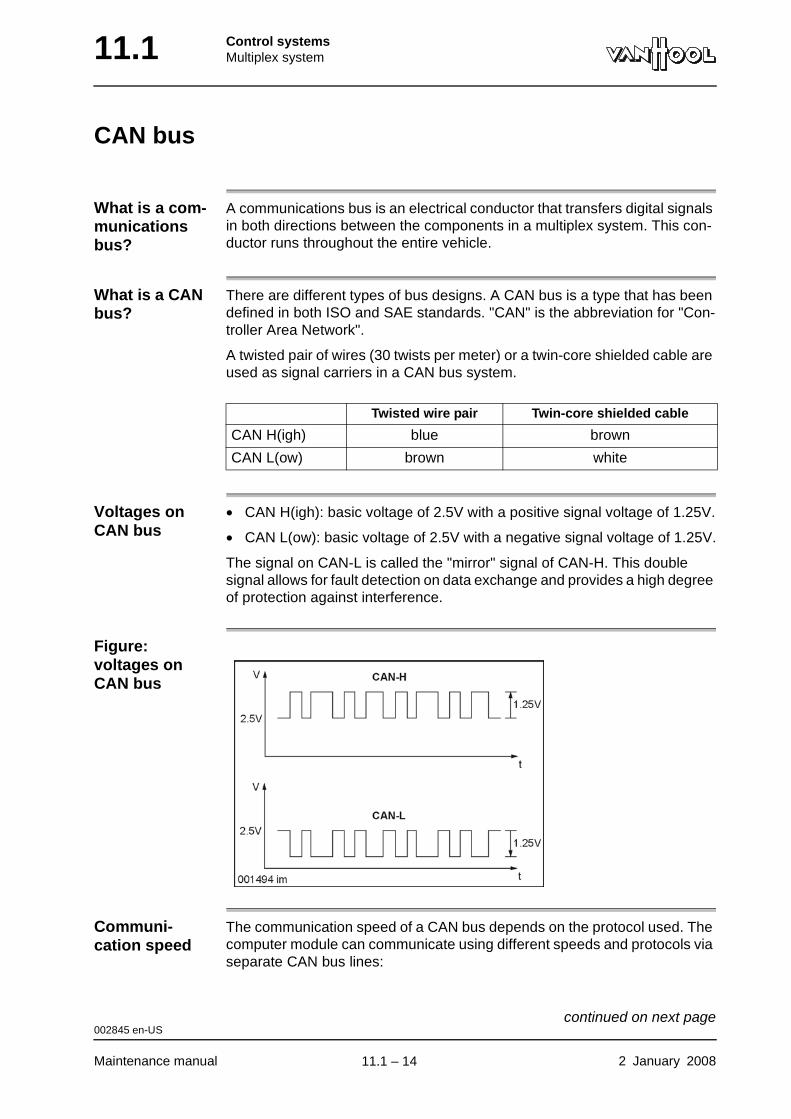
11.1 Control systemsMultiplex system
CAN bus
What is a com-munications bus?
A communications bus is an electrical conductor that transfers digital signals in both directions between the components in a multiplex system. This con-ductor runs throughout the entire vehicle.
What is a CAN bus?
There are different types of bus designs. A CAN bus is a type that has been defined in both ISO and SAE standards. "CAN" is the abbreviation for "Con-troller Area Network".
A twisted pair of wires (30 twists per meter) or a twin-core shielded cable are used as signal carriers in a CAN bus system.
Voltages on CAN bus
• CAN H(igh): basic voltage of 2.5V with a positive signal voltage of 1.25V.
• CAN L(ow): basic voltage of 2.5V with a negative signal voltage of 1.25V.
The signal on CAN-L is called the "mirror" signal of CAN-H. This double signal allows for fault detection on data exchange and provides a high degree of protection against interference.
Figure: voltages on CAN bus
Communi-cation speed
The communication speed of a CAN bus depends on the protocol used. The computer module can communicate using different speeds and protocols via separate CAN bus lines:
Twisted wire pair Twin-core shielded cable
CAN H(igh) blue brown
CAN L(ow) brown white
002845 en-US
Maintenance manual 2 January 2008
continued on next page.
11.1 – 14
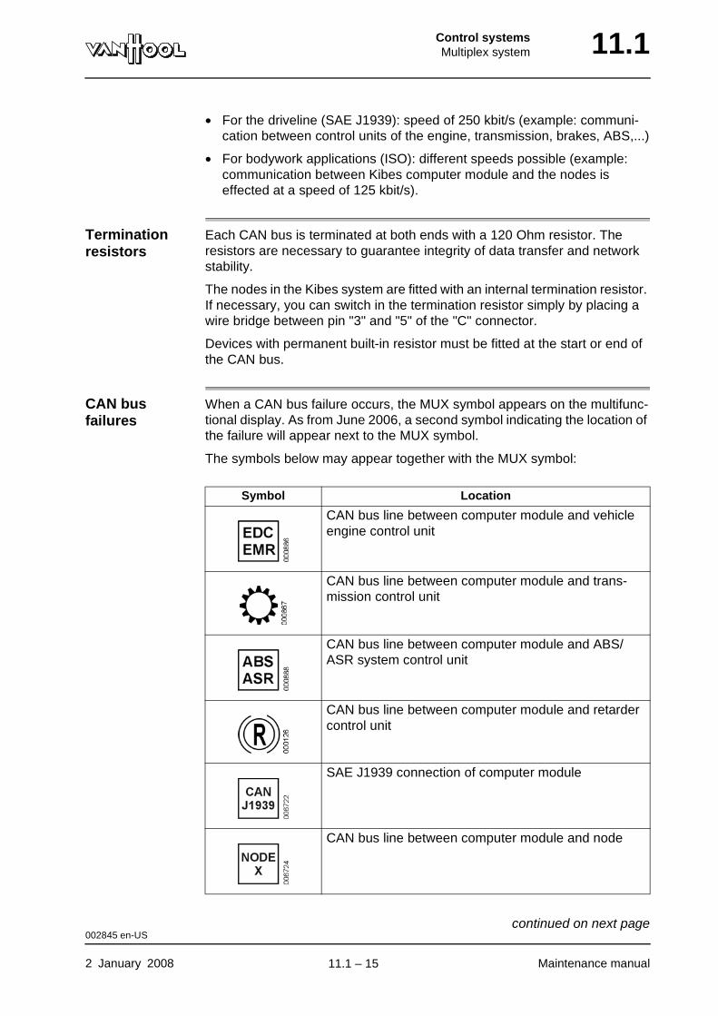
Control systemsMultiplex system 11.1
• For the driveline (SAE J1939): speed of 250 kbit/s (example: communi-cation between control units of the engine, transmission, brakes, ABS,...)
• For bodywork applications (ISO): different speeds possible (example: communication between Kibes computer module and the nodes is effected at a speed of 125 kbit/s).
Termination resistors
Each CAN bus is terminated at both ends with a 120 Ohm resistor. The resistors are necessary to guarantee integrity of data transfer and network stability.
The nodes in the Kibes system are fitted with an internal termination resistor. If necessary, you can switch in the termination resistor simply by placing a wire bridge between pin "3" and "5" of the "C" connector.
Devices with permanent built-in resistor must be fitted at the start or end of the CAN bus.
CAN bus failures
When a CAN bus failure occurs, the MUX symbol appears on the multifunc-tional display. As from June 2006, a second symbol indicating the location of the failure will appear next to the MUX symbol.
The symbols below may appear together with the MUX symbol:
Symbol Location
CAN bus line between computer module and vehicle engine control unit
CAN bus line between computer module and trans-mission control unit
CAN bus line between computer module and ABS/ASR system control unit
CAN bus line between computer module and retarder control unit
SAE J1939 connection of computer module
CAN bus line between computer module and node
002845 en-US
2 January 2008 Maintenance manual
continued on next page.
11.1 – 15
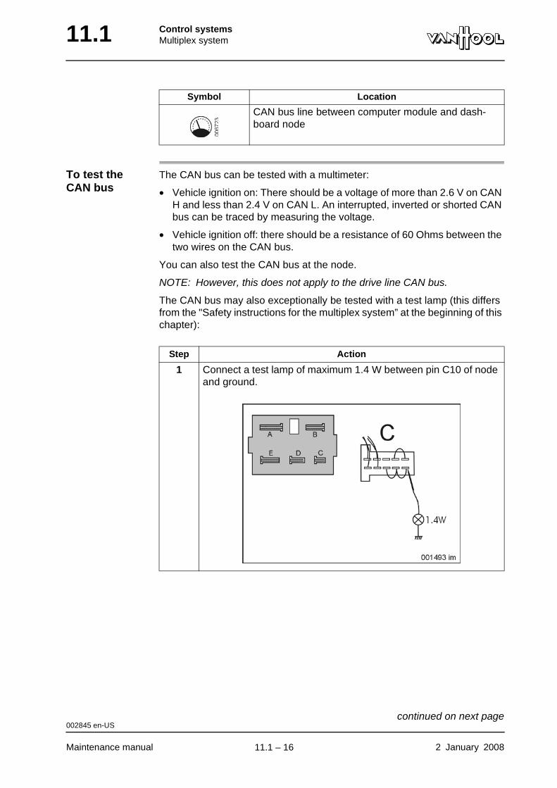
11.1 Control systemsMultiplex system
To test the CAN bus
The CAN bus can be tested with a multimeter:
• Vehicle ignition on: There should be a voltage of more than 2.6 V on CAN H and less than 2.4 V on CAN L. An interrupted, inverted or shorted CAN bus can be traced by measuring the voltage.
• Vehicle ignition off: there should be a resistance of 60 Ohms between the two wires on the CAN bus.
You can also test the CAN bus at the node.
NOTE: However, this does not apply to the drive line CAN bus.
The CAN bus may also exceptionally be tested with a test lamp (this differs from the "Safety instructions for the multiplex system” at the beginning of this chapter):
CAN bus line between computer module and dash-board node
Symbol Location
Step Action
1 Connect a test lamp of maximum 1.4 W between pin C10 of node and ground.
002845 en-US
Maintenance manual 2 January 2008
continued on next page.
11.1 – 16
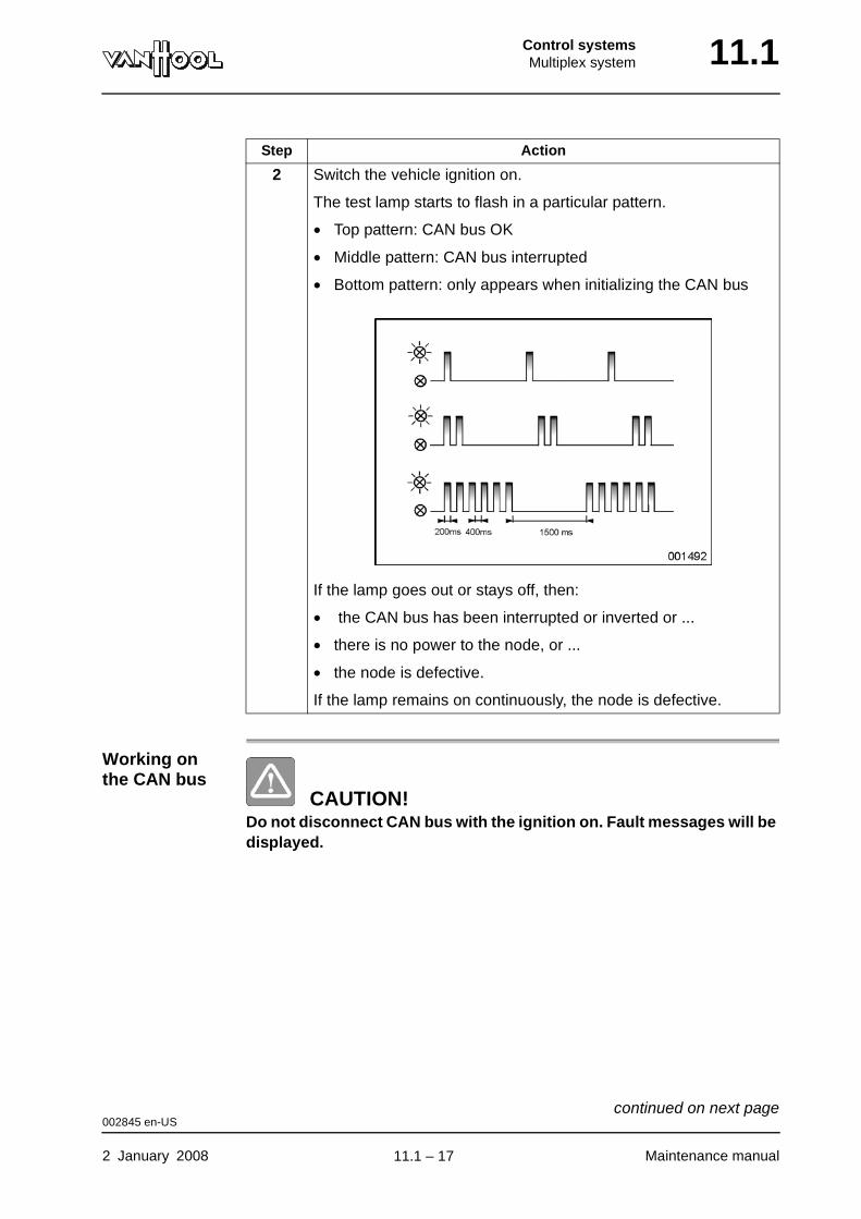
Control systemsMultiplex system 11.1
Working on the CAN bus
CAUTION!Do not disconnect CAN bus with the ignition on. Fault messages will be displayed.
2 Switch the vehicle ignition on.
The test lamp starts to flash in a particular pattern.
• Top pattern: CAN bus OK
• Middle pattern: CAN bus interrupted
• Bottom pattern: only appears when initializing the CAN bus
If the lamp goes out or stays off, then:
• the CAN bus has been interrupted or inverted or ...
• there is no power to the node, or ...
• the node is defective.
If the lamp remains on continuously, the node is defective.
Step Action
002845 en-US
2 January 2008 Maintenance manual
continued on next page.
11.1 – 17
11.1 Control systemsMultiplex system
After working on the CAN bus CAUTION!
The multiplex system must be reset after work has been carried out on the CAN bus.
Follow the procedure below to reset the multiplex system:
Failure of the CAN bus
If the CAN bus fails, the affected node switches to an emergency program that activates specific outputs.
In practice, this means that the outputs of the exterior lighting (front and rear position lamps) connected to this node are activated. This guarantees vehicle safety (visibility).
Step Action
1 Switch off the vehicle ignition.
2 Wait for 30 seconds.
3 Turn the central emergency switch off and on.
The multiplex system is reset.
002845 en-US
Maintenance manual 2 January 2008
.
11.1 – 18
Control systemsMultiplex system 11.1
Technology of node inputs and outputs
Node inputs There are two types of input: static and analog.
Static inputs The static inputs can be powered in different ways: positive (S3), ground (S2) or by a combination of both (S1).
NOTE: You measure a voltage of about half the on-board voltage at the input if the switch is open.
A(n) ... input changes the voltage level to ...
static "0" or "1" (e.g. switch off or on). This digital data is then sent via the CAN bus to the computer module for pro-cessing.
NOTE: The current flow required to operate a static input is only 7mA.
analog a digital value that corresponds to the magnitude of the input signal (e.g. fuel gauge float).
Switch setting Voltage at node input Digital signal
S1a
a. This way of switching allows you to determine with a voltmeter whether the switch itself is faulty or whether there is an interruption in the wiring to the node. This switching method is sometimes used with the dashboard node.
ground switched lower than 5V 0
positive switched higher than 19 V 1
S2 closed (to ground) lower than 5 V 1
open higher than 7 V 0
S3 open lower than 16 V 0
closed (to positive) higher than 19 V 1
002860 en-US
2 January 2008 Maintenance manual
continued on next page.
11.1 – 19

11.1 Control systemsMultiplex system
Figure: switching pos-sibilities at static node input
Ub: on-board voltage
S1 Change-over switchS2 Ground switchedS3 Positive switched
Electronic circuit at static node input
As mentioned above under "Static inputs", there is a voltage equal to approx-imately half the on-board voltage at the node input, if the switch is open. If you connect an electronic circuit to the node input, in parallel with the switch, then the node input voltage can affect the input of that electronic circuit. To avoid this, a diode (see figure for the correct direction) is placed in the wiring to the electronic circuit.
Figure: electronic circuit at static node input
Ub: on-board voltage
1 Electronic circuit
002860 en-US
Maintenance manual 2 January 2008
continued on next page.
11.1 – 20
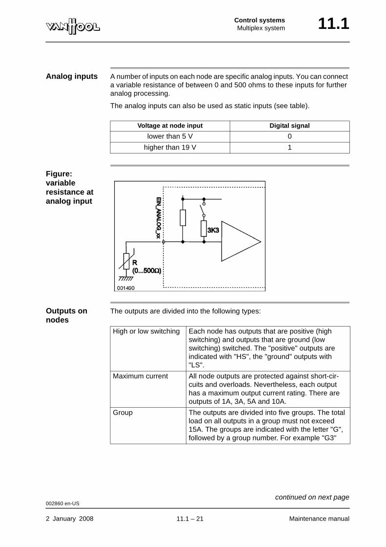
Control systemsMultiplex system 11.1
Analog inputs A number of inputs on each node are specific analog inputs. You can connect a variable resistance of between 0 and 500 ohms to these inputs for further analog processing.
The analog inputs can also be used as static inputs (see table).
Figure: variable resistance at analog input
Outputs on nodes
The outputs are divided into the following types:
Voltage at node input Digital signal
lower than 5 V 0
higher than 19 V 1
High or low switching Each node has outputs that are positive (high switching) and outputs that are ground (low switching) switched. The "positive" outputs are indicated with "HS", the "ground" outputs with "LS".
Maximum current All node outputs are protected against short-cir-cuits and overloads. Nevertheless, each output has a maximum output current rating. There are outputs of 1A, 3A, 5A and 10A.
Group The outputs are divided into five groups. The total load on all outputs in a group must not exceed 15A. The groups are indicated with the letter "G", followed by a group number. For example "G3"
002860 en-US
2 January 2008 Maintenance manual
continued on next page.
11.1 – 21
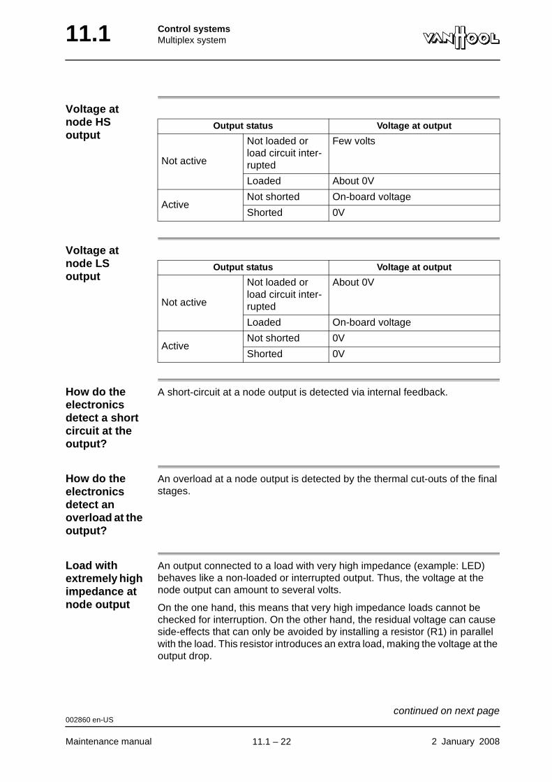
11.1 Control systemsMultiplex system
Voltage at node HS output
Voltage at node LS output
How do the electronics detect a short circuit at the output?
A short-circuit at a node output is detected via internal feedback.
How do the electronics detect an overload at the output?
An overload at a node output is detected by the thermal cut-outs of the final stages.
Load with extremely high impedance at node output
An output connected to a load with very high impedance (example: LED) behaves like a non-loaded or interrupted output. Thus, the voltage at the node output can amount to several volts.
On the one hand, this means that very high impedance loads cannot be checked for interruption. On the other hand, the residual voltage can cause side-effects that can only be avoided by installing a resistor (R1) in parallel with the load. This resistor introduces an extra load, making the voltage at the output drop.
Output status Voltage at output
Not active
Not loaded or load circuit inter-rupted
Few volts
Loaded About 0V
ActiveNot shorted On-board voltage
Shorted 0V
Output status Voltage at output
Not active
Not loaded or load circuit inter-rupted
About 0V
Loaded On-board voltage
ActiveNot shorted 0V
Shorted 0V
002860 en-US
Maintenance manual 2 January 2008
continued on next page.
11.1 – 22
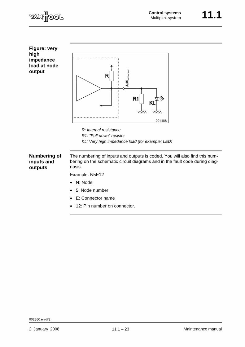
Control systemsMultiplex system 11.1
Figure: very high impedance load at node output
R: Internal resistanceR1: "Pull-down" resistorKL: Very high impedance load (for example: LED)
Numbering of inputs and outputs
The numbering of inputs and outputs is coded. You will also find this num-bering on the schematic circuit diagrams and in the fault code during diag-nosis.
Example: N5E12
• N: Node
• 5: Node number
• E: Connector name
• 12: Pin number on connector.
002860 en-US
2 January 2008 Maintenance manual
.
11.1 – 23
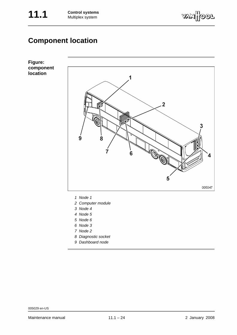
11.1 Control systemsMultiplex system
Component location
Figure: component location
1 Node 12 Computer module3 Node 44 Node 55 Node 66 Node 37 Node 28 Diagnostic socket9 Dashboard node
005029 en-US
Maintenance manual 2 January 2008
.
11.1 – 24

Control systemsMultiplex system 11.1
To operate the multifunctional display
Introduction The aids for testing and the diagnostic systems are activated with the buttons located under the multifunctional display.
Figure: activation buttons of central multi-functional display
1 Menu button2 Selection buttons3 Adjusting button for the brightness of the dashboard instruments
Function of control buttons
WARNING!Before operating the multifunctional display to perform simulations or functional tests via the multiplex system, warn people working on the vehicle or about to do so that climate-control system fans and other devices may suddenly engage without the engine running.
Button Function
Menu button • To open/close service menu
• To return to previous menu.
Selection buttons Select the symbols in the lower part of the display to:
• open the submenu;
• select functions in the submenu.
002744 en-US
2 January 2008 Maintenance manual
continued on next page.
11.1 – 25
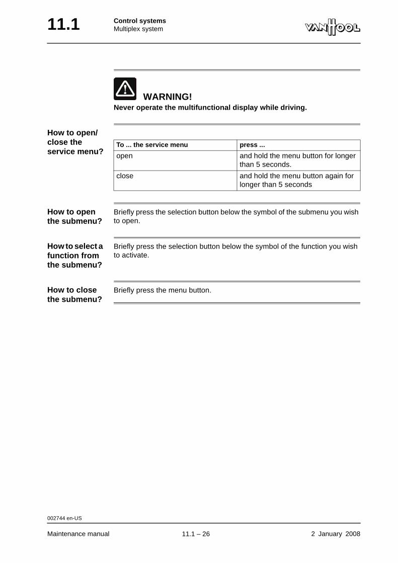
11.1 Control systemsMultiplex system
WARNING!Never operate the multifunctional display while driving.
How to open/close the service menu?
How to open the submenu?
Briefly press the selection button below the symbol of the submenu you wish to open.
How to select a function from the submenu?
Briefly press the selection button below the symbol of the function you wish to activate.
How to close the submenu?
Briefly press the menu button.
To ... the service menu press ...
open and hold the menu button for longer than 5 seconds.
close and hold the menu button again for longer than 5 seconds
002744 en-US
Maintenance manual 2 January 2008
.
11.1 – 26
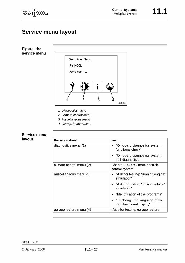
Control systemsMultiplex system 11.1
Service menu layout
Figure: the service menu
1 Diagnostics menu2 Climate-control menu3 Miscellaneous menu4 Garage feature menu
Service menu layout For more about ... see ...
diagnostics menu (1) • "On-board diagnostics system: functional check"
• "On-board diagnostics system: self-diagnosis".
climate-control menu (2) Chapter 8.02: “Climate control: control system"
miscellaneous menu (3) • "Aids for testing: "running engine" simulation"
• "Aids for testing: "driving vehicle" simulation"
• "Identification of the programs"
• "To change the language of the multifunctional display"
garage feature menu (4) "Aids for testing: garage feature"
002843 en-US
2 January 2008 Maintenance manual
.
11.1 – 27
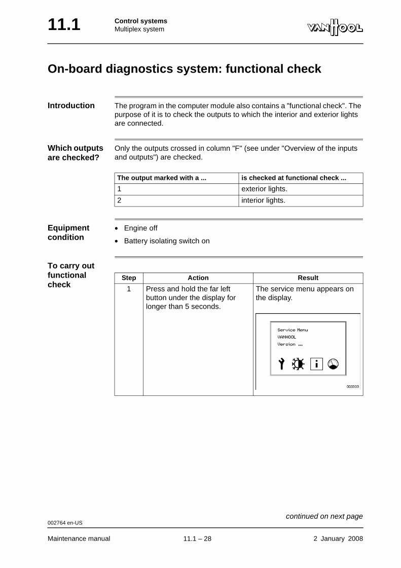
11.1 Control systemsMultiplex system
On-board diagnostics system: functional check
Introduction The program in the computer module also contains a "functional check". The purpose of it is to check the outputs to which the interior and exterior lights are connected.
Which outputs are checked?
Only the outputs crossed in column "F" (see under "Overview of the inputs and outputs") are checked.
Equipment condition
• Engine off
• Battery isolating switch on
To carry out functional check
The output marked with a ... is checked at functional check ...
1 exterior lights.
2 interior lights.
Step Action Result
1 Press and hold the far left button under the display for longer than 5 seconds.
The service menu appears on the display.
002764 en-US
Maintenance manual 2 January 2008
continued on next page.
11.1 – 28
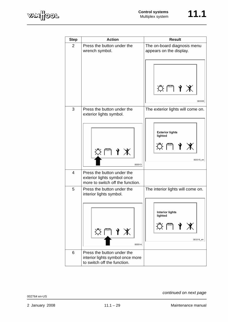
Control systemsMultiplex system 11.1
2 Press the button under the wrench symbol.
The on-board diagnosis menu appears on the display.
3 Press the button under the exterior lights symbol.
The exterior lights will come on.
4 Press the button under the exterior lights symbol once more to switch off the function.
5 Press the button under the interior lights symbol.
The interior lights will come on.
6 Press the button under the interior lights symbol once more to switch off the function.
Step Action Result
002764 en-US
2 January 2008 Maintenance manual
continued on next page.
11.1 – 29
11.1 Control systemsMultiplex system
To exit functional check
Briefly press the far left button of the multifunctional display as many times as needed to return to the service menu.
002764 en-US
Maintenance manual 2 January 2008
.
11.1 – 30
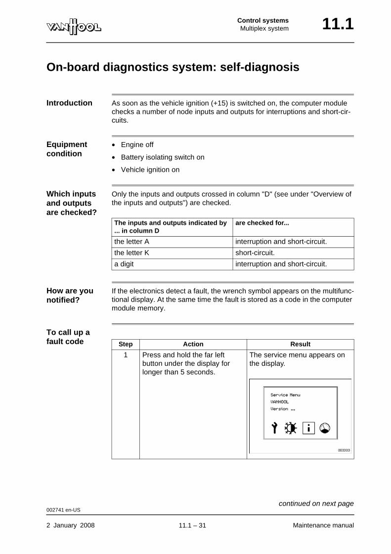
Control systemsMultiplex system 11.1
On-board diagnostics system: self-diagnosis
Introduction As soon as the vehicle ignition (+15) is switched on, the computer module checks a number of node inputs and outputs for interruptions and short-cir-cuits.
Equipment condition
• Engine off
• Battery isolating switch on
• Vehicle ignition on
Which inputs and outputs are checked?
Only the inputs and outputs crossed in column "D" (see under "Overview of the inputs and outputs") are checked.
How are you notified?
If the electronics detect a fault, the wrench symbol appears on the multifunc-tional display. At the same time the fault is stored as a code in the computer module memory.
To call up a fault code
The inputs and outputs indicated by ... in column D
are checked for...
the letter A interruption and short-circuit.
the letter K short-circuit.
a digit interruption and short-circuit.
Step Action Result
1 Press and hold the far left button under the display for longer than 5 seconds.
The service menu appears on the display.
002741 en-US
2 January 2008 Maintenance manual
continued on next page.
11.1 – 31
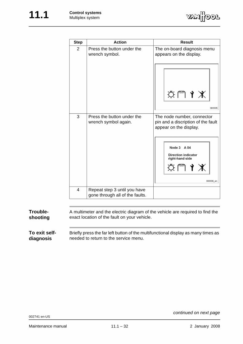
11.1 Control systemsMultiplex system
Trouble-shooting
A multimeter and the electric diagram of the vehicle are required to find the exact location of the fault on your vehicle.
To exit self-diagnosis
Briefly press the far left button of the multifunctional display as many times as needed to return to the service menu.
2 Press the button under the wrench symbol.
The on-board diagnosis menu appears on the display.
3 Press the button under the wrench symbol again.
The node number, connector pin and a discription of the fault appear on the display.
4 Repeat step 3 until you have gone through all of the faults.
Step Action Result
002741 en-US
Maintenance manual 2 January 2008
continued on next page.
11.1 – 32
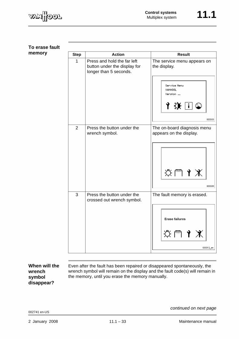
Control systemsMultiplex system 11.1
To erase fault memory
When will the wrench symbol disappear?
Even after the fault has been repaired or disappeared spontaneously, the wrench symbol will remain on the display and the fault code(s) will remain in the memory, until you erase the memory manually.
Step Action Result
1 Press and hold the far left button under the display for longer than 5 seconds.
The service menu appears on the display.
2 Press the button under the wrench symbol.
The on-board diagnosis menu appears on the display.
3 Press the button under the crossed out wrench symbol.
The fault memory is erased.
002741 en-US
2 January 2008 Maintenance manual
continued on next page.
11.1 – 33
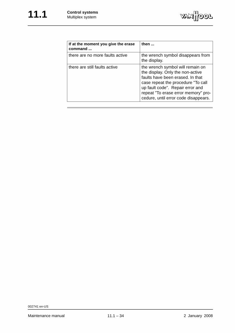
11.1 Control systemsMultiplex system
If at the moment you give the erase command ...
then ...
there are no more faults active the wrench symbol disappears from the display.
there are still faults active the wrench symbol will remain on the display. Only the non-active faults have been erased. In that case repeat the procedure "To call up fault code". Repair error and repeat "To erase error memory" pro-cedure, until error code disappears.
002741 en-US
Maintenance manual 2 January 2008
.
11.1 – 34

Control systemsMultiplex system 11.1
Aids for testing: "running engine" simulation
Introduction A number of electrical circuits are only powered when the vehicle engine is running. It may occasionally be necessary to simulate the electrical signal of the 'turning engine' (D+) in order to test these electrical circuits without the engine actually being in operation.
Equipment condition
• Engine off
• Battery isolating switch on
To start simulation Step Action Result
1 Press and hold the far left button under the display for longer than 5 seconds.
The service menu appears on the display.
2 Press the button under the "i" symbol.
The miscellaneous menu appears on the display.
002771 en-US
2 January 2008 Maintenance manual
continued on next page.
11.1 – 35
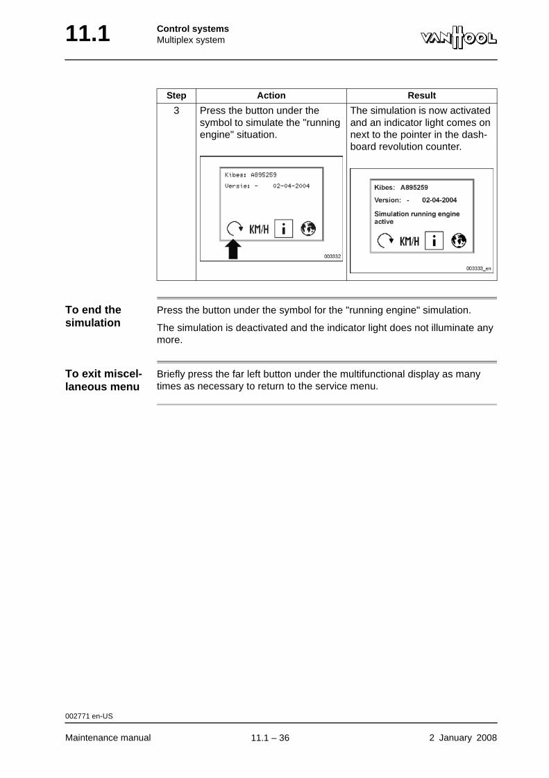
11.1 Control systemsMultiplex system
To end the simulation
Press the button under the symbol for the "running engine" simulation.
The simulation is deactivated and the indicator light does not illuminate any more.
To exit miscel-laneous menu
Briefly press the far left button under the multifunctional display as many times as necessary to return to the service menu.
3 Press the button under the symbol to simulate the "running engine" situation.
The simulation is now activated and an indicator light comes on next to the pointer in the dash-board revolution counter.
Step Action Result
002771 en-US
Maintenance manual 2 January 2008
.
11.1 – 36

Control systemsMultiplex system 11.1
Aids for testing: "moving vehicle" simulation
Introduction A number of electrical circuits are only powered when the vehicle is in motion. It may occassionally be necessary to simulate the electrical signal of a "moving vehicle" to enable these circuits to be tested without the vehcile actually moving.
NOTE: When you start this function, the "running engine" simulation will also start. This is in order to approximate a realistic situation as closely as pos-sible.
Equipment condition
• Engine off
• Battery isolating switch on
To start simulation Step Action Result
1 Press and hold the far left button of the display for longer than 5 seconds.
The service menu appears on the display.
2 Press the button under the "i" symbol.
The miscellaneous menu appears on the display.
002772 en-US
2 January 2008 Maintenance manual
continued on next page.
11.1 – 37
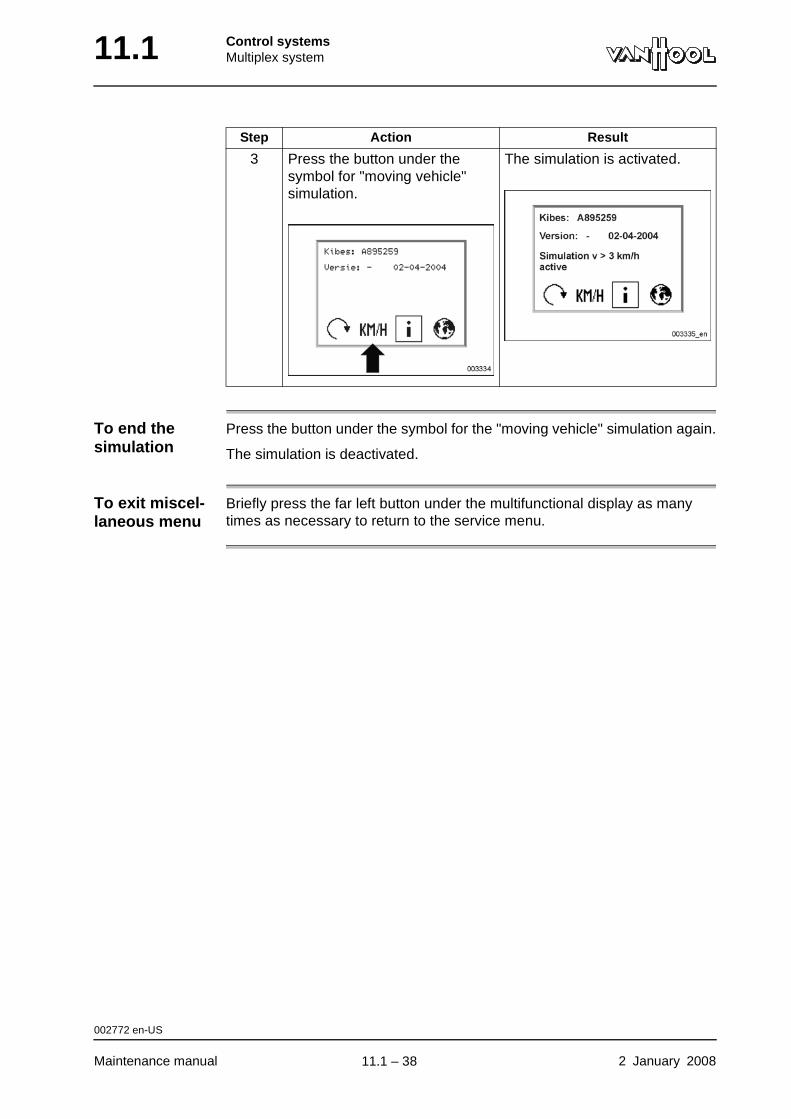
11.1 Control systemsMultiplex system
To end the simulation
Press the button under the symbol for the "moving vehicle" simulation again.
The simulation is deactivated.
To exit miscel-laneous menu
Briefly press the far left button under the multifunctional display as many times as necessary to return to the service menu.
3 Press the button under the symbol for "moving vehicle" simulation.
The simulation is activated.
Step Action Result
002772 en-US
Maintenance manual 2 January 2008
.
11.1 – 38
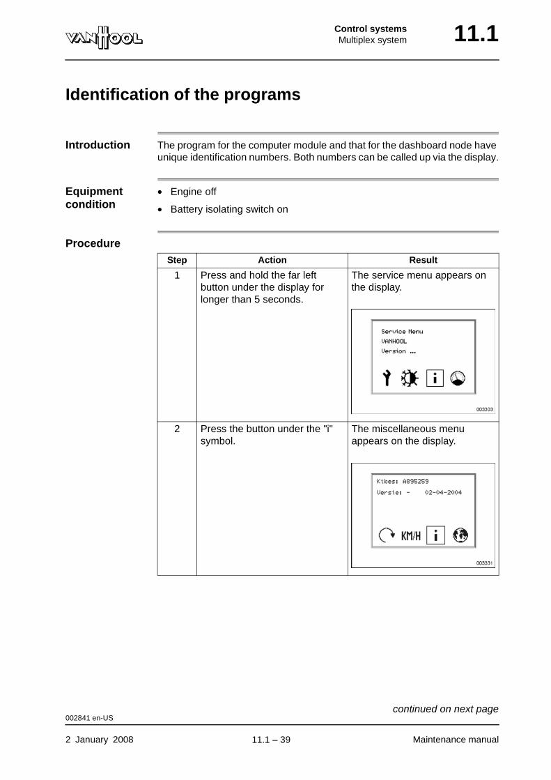
Control systemsMultiplex system 11.1
Identification of the programs
Introduction The program for the computer module and that for the dashboard node have unique identification numbers. Both numbers can be called up via the display.
Equipment condition
• Engine off
• Battery isolating switch on
ProcedureStep Action Result
1 Press and hold the far left button under the display for longer than 5 seconds.
The service menu appears on the display.
2 Press the button under the "i" symbol.
The miscellaneous menu appears on the display.
002841 en-US
2 January 2008 Maintenance manual
continued on next page.
11.1 – 39
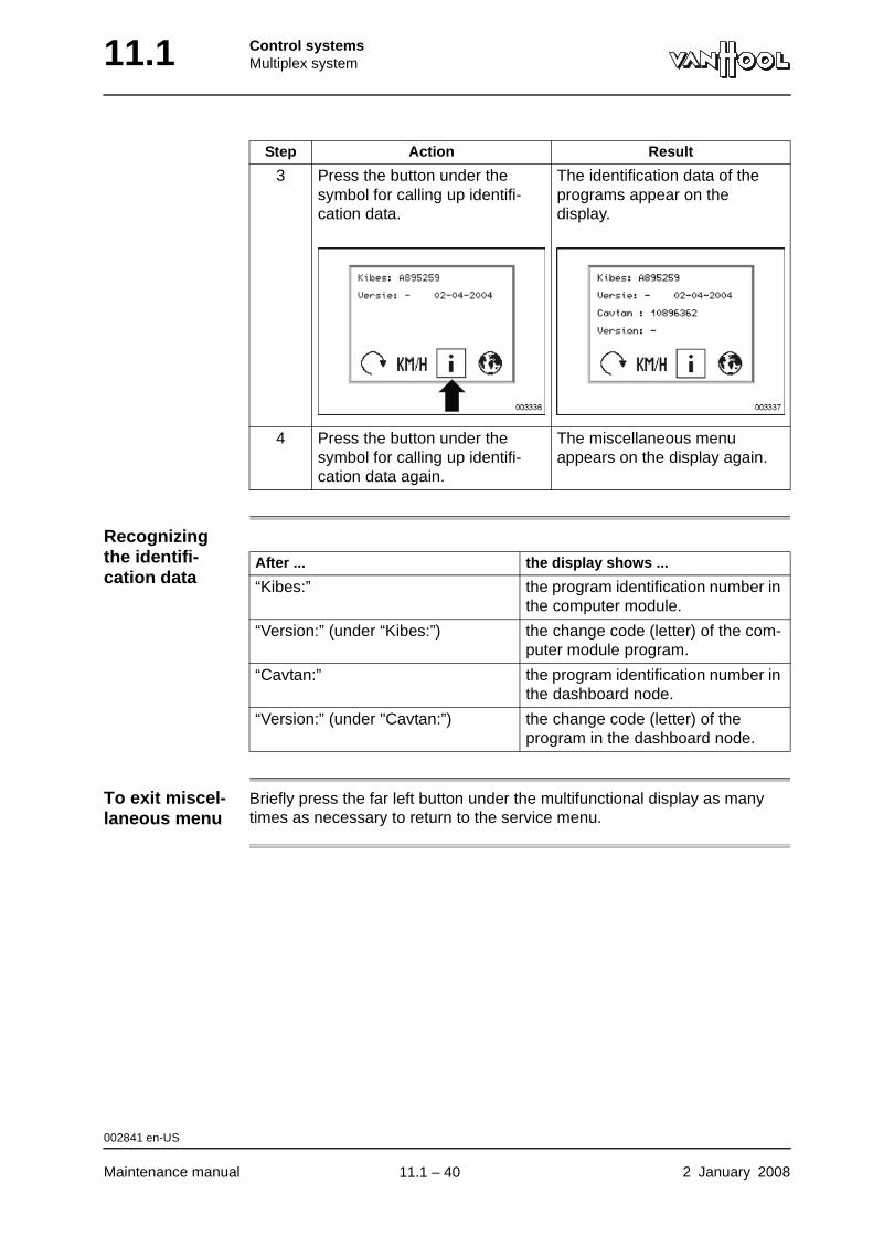
11.1 Control systemsMultiplex system
Recognizing the identifi-cation data
To exit miscel-laneous menu
Briefly press the far left button under the multifunctional display as many times as necessary to return to the service menu.
3 Press the button under the symbol for calling up identifi-cation data.
The identification data of the programs appear on the display.
4 Press the button under the symbol for calling up identifi-cation data again.
The miscellaneous menu appears on the display again.
Step Action Result
After ... the display shows ...
“Kibes:” the program identification number in the computer module.
“Version:” (under “Kibes:”) the change code (letter) of the com-puter module program.
“Cavtan:” the program identification number in the dashboard node.
“Version:” (under "Cavtan:”) the change code (letter) of the program in the dashboard node.
002841 en-US
Maintenance manual 2 January 2008
.
11.1 – 40
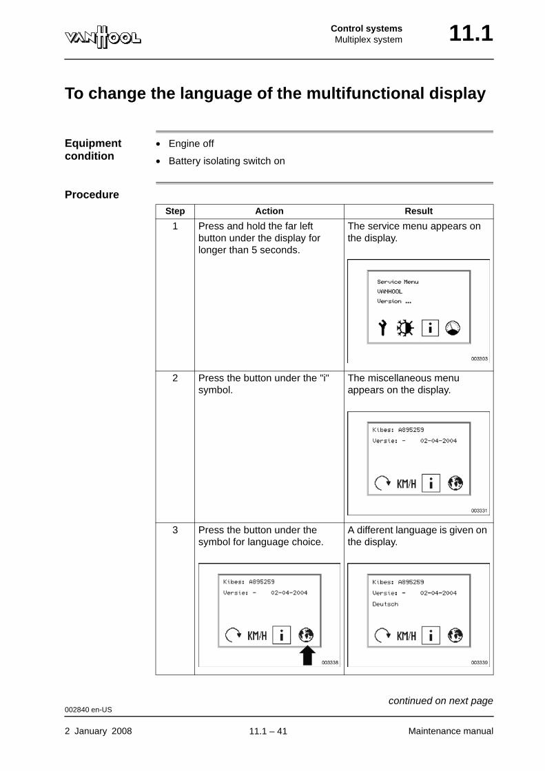
Control systemsMultiplex system 11.1
To change the language of the multifunctional display
Equipment condition
• Engine off
• Battery isolating switch on
ProcedureStep Action Result
1 Press and hold the far left button under the display for longer than 5 seconds.
The service menu appears on the display.
2 Press the button under the "i" symbol.
The miscellaneous menu appears on the display.
3 Press the button under the symbol for language choice.
A different language is given on the display.
002840 en-US
2 January 2008 Maintenance manual
continued on next page.
11.1 – 41
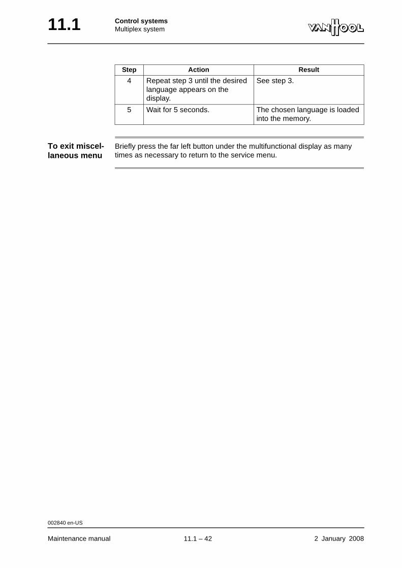
11.1 Control systemsMultiplex system
To exit miscel-laneous menu
Briefly press the far left button under the multifunctional display as many times as necessary to return to the service menu.
4 Repeat step 3 until the desired language appears on the display.
See step 3.
5 Wait for 5 seconds. The chosen language is loaded into the memory.
Step Action Result
002840 en-US
Maintenance manual 2 January 2008
.
11.1 – 42
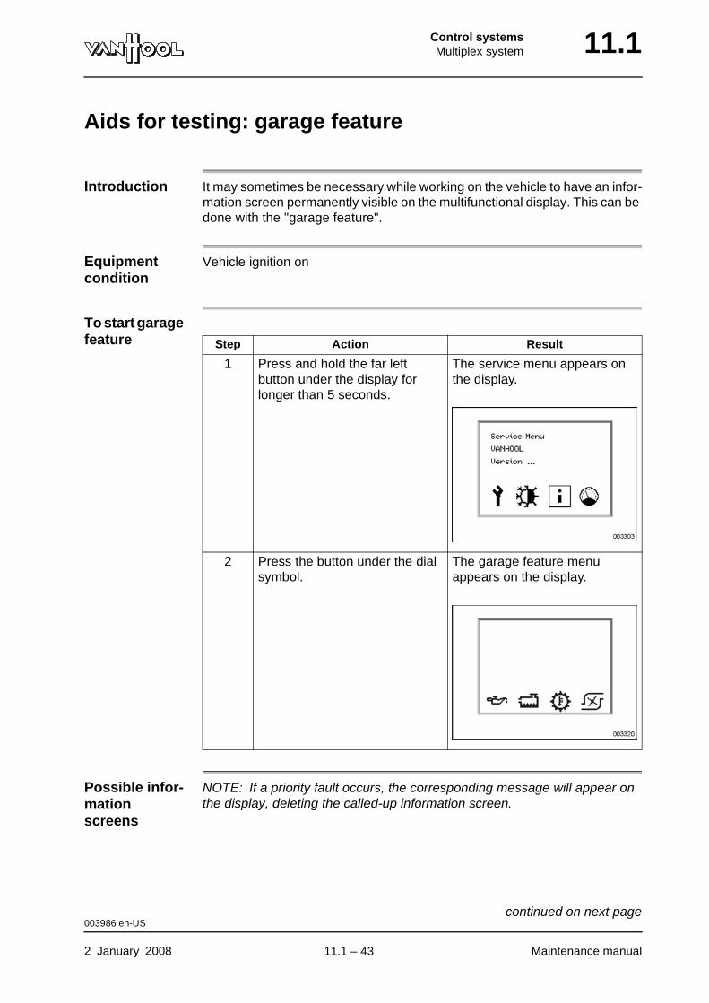
Control systemsMultiplex system 11.1
Aids for testing: garage feature
Introduction It may sometimes be necessary while working on the vehicle to have an infor-mation screen permanently visible on the multifunctional display. This can be done with the "garage feature".
Equipment condition
Vehicle ignition on
To start garage feature
Possible infor-mation screens
NOTE: If a priority fault occurs, the corresponding message will appear on the display, deleting the called-up information screen.
Step Action Result
1 Press and hold the far left button under the display for longer than 5 seconds.
The service menu appears on the display.
2 Press the button under the dial symbol.
The garage feature menu appears on the display.
003986 en-US
2 January 2008 Maintenance manual
continued on next page.
11.1 – 43
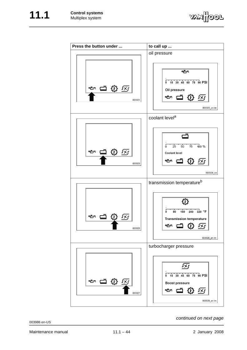
11.1 Control systemsMultiplex system
Press the button under ... to call up ...
oil pressure
coolant levela
transmission temperatureb
turbocharger pressure
003986 en-US
Maintenance manual 2 January 2008
continued on next page.
11.1 – 44
Control systemsMultiplex system 11.1
To exit garage feature
Briefly press the far left button under the multifunctional display as many times as necessary to return to the service menu.
a. Not available for T2100.
b. Only available in case of a WT transmission.
003986 en-US
2 January 2008 Maintenance manual
.
11.1 – 45
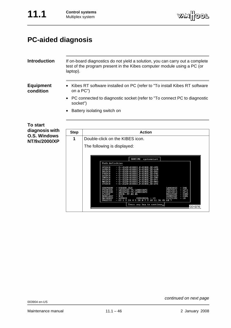
11.1 Control systemsMultiplex system
PC-aided diagnosis
Introduction If on-board diagnostics do not yield a solution, you can carry out a complete test of the program present in the Kibes computer module using a PC (or laptop).
Equipment condition
• Kibes RT software installed on PC (refer to "To install Kibes RT software on a PC")
• PC connected to diagnostic socket (refer to "To connect PC to diagnostic socket")
• Battery isolating switch on
To start diagnosis with O.S. Windows NT/9x/2000/XP
Step Action
1 Double-click on the KIBES icon.
The following is displayed:
003904 en-US
Maintenance manual 2 January 2008
continued on next page.
11.1 – 46

Control systemsMultiplex system 11.1
2 Press any key.
The following is displayed:
3 Select "POSTPROCESSORS" from the menu and press ENTER.
Step Action
003904 en-US
2 January 2008 Maintenance manual
continued on next page.
11.1 – 47
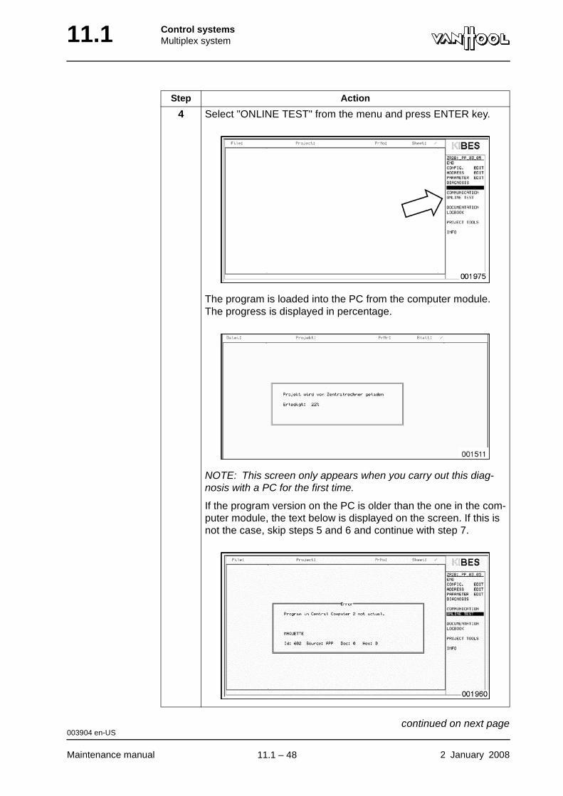
11.1 Control systemsMultiplex system
4 Select "ONLINE TEST" from the menu and press ENTER key.
The program is loaded into the PC from the computer module. The progress is displayed in percentage.
NOTE: This screen only appears when you carry out this diag-nosis with a PC for the first time.
If the program version on the PC is older than the one in the com-puter module, the text below is displayed on the screen. If this is not the case, skip steps 5 and 6 and continue with step 7.
Step Action
003904 en-US
Maintenance manual 2 January 2008
continued on next page.
11.1 – 48
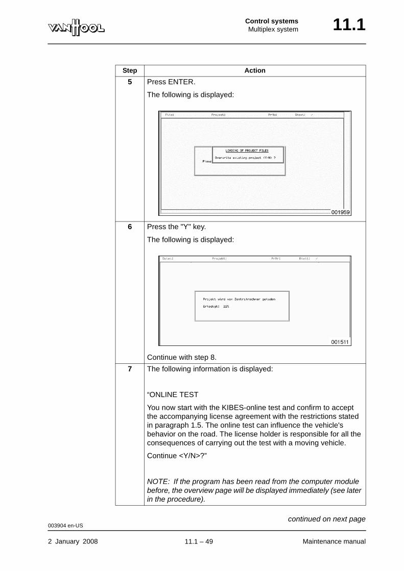
Control systemsMultiplex system 11.1
5 Press ENTER.
The following is displayed:
6 Press the "Y" key.
The following is displayed:
Continue with step 8.
7 The following information is displayed:
“ONLINE TEST
You now start with the KIBES-online test and confirm to accept the accompanying license agreement with the restrictions stated in paragraph 1.5. The online test can influence the vehicle's behavior on the road. The license holder is responsible for all the consequences of carrying out the test with a moving vehicle.
Continue <Y/N>?”
NOTE: If the program has been read from the computer module before, the overview page will be displayed immediately (see later in the procedure).
Step Action
003904 en-US
2 January 2008 Maintenance manual
continued on next page.
11.1 – 49
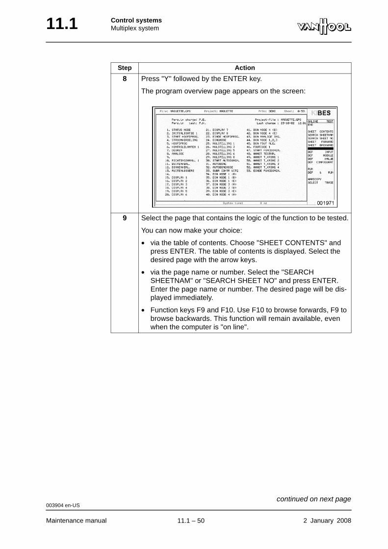
11.1 Control systemsMultiplex system
8 Press "Y" followed by the ENTER key.
The program overview page appears on the screen:
9 Select the page that contains the logic of the function to be tested.
You can now make your choice:
• via the table of contents. Choose "SHEET CONTENTS" and press ENTER. The table of contents is displayed. Select the desired page with the arrow keys.
• via the page name or number. Select the "SEARCH SHEETNAM" or "SEARCH SHEET NO" and press ENTER. Enter the page name or number. The desired page will be dis-played immediately.
• Function keys F9 and F10. Use F10 to browse forwards, F9 to browse backwards. This function will remain available, even when the computer is "on line".
Step Action
003904 en-US
Maintenance manual 2 January 2008
continued on next page.
11.1 – 50

Control systemsMultiplex system 11.1
To end diagnosis
10 Select "DEF & RUN" from the menu and press ENTER.
The "ON LINE" function is now active.
The status of the inputs and outputs can now be followed on screen. A thick blue line means "active", a thin line means "not active".
Step Action
Step Action
1 Press "ESC" key.
003904 en-US
2 January 2008 Maintenance manual
continued on next page.
11.1 – 51
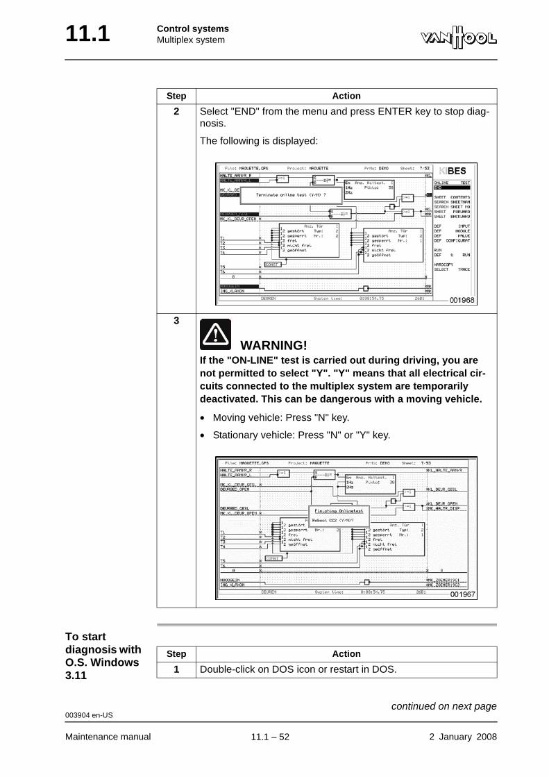
11.1 Control systemsMultiplex system
To start diagnosis with O.S. Windows 3.11
2 Select "END" from the menu and press ENTER key to stop diag-nosis.
The following is displayed:
3
WARNING!If the "ON-LINE" test is carried out during driving, you are not permitted to select "Y". "Y" means that all electrical cir-cuits connected to the multiplex system are temporarily deactivated. This can be dangerous with a moving vehicle.
• Moving vehicle: Press "N" key.
• Stationary vehicle: Press "N" or "Y" key.
Step Action
Step Action
1 Double-click on DOS icon or restart in DOS.
003904 en-US
Maintenance manual 2 January 2008
continued on next page.
11.1 – 52
Control systemsMultiplex system 11.1
To start diagnosis with O.S. DOS
What if there is a communi-cation error?
See "Troubleshooting" under "Diagnosis with a PC"".
2 Type "KS" and press ENTER key.
3 Continue with steps 2 to 10 under "To start diagnosis with O.S. Windows NT/9x/2000/XP".
Step Action
Step Action
1 Type "KS" and press ENTER key.
2 Continue with steps 2 to 10 under "To start diagnosis with O.S. Windows NT/9x/2000/XP".
003904 en-US
2 January 2008 Maintenance manual
.
11.1 – 53
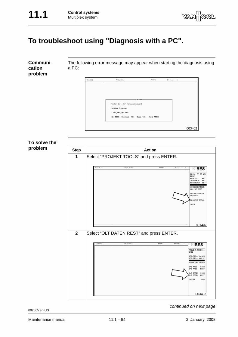
11.1 Control systemsMultiplex system
To troubleshoot using "Diagnosis with a PC".
Communi-cation problem
The following error message may appear when starting the diagnosis using a PC:
To solve the problem Step Action
1 Select “PROJEKT TOOLS” and press ENTER.
2 Select “OLT DATEN REST” and press ENTER.
002865 en-US
Maintenance manual 2 January 2008
continued on next page.
11.1 – 54
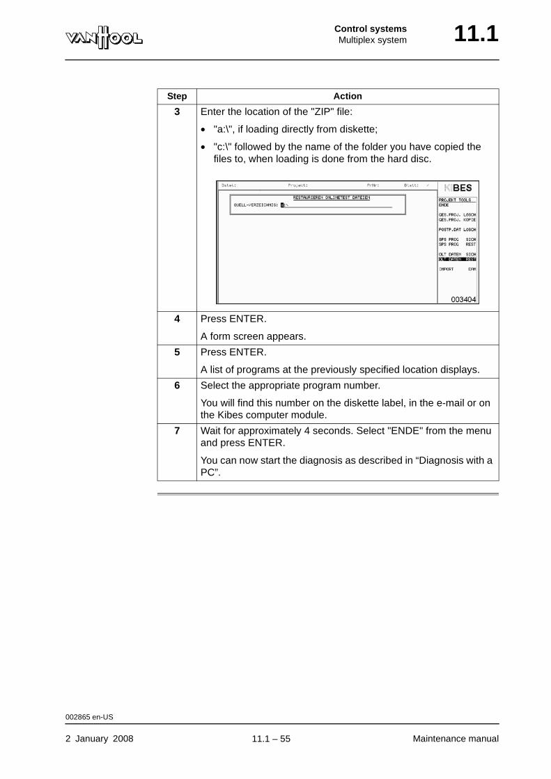
Control systemsMultiplex system 11.1
3 Enter the location of the "ZIP" file:
• "a:\", if loading directly from diskette;
• "c:\" followed by the name of the folder you have copied the files to, when loading is done from the hard disc.
4 Press ENTER.
A form screen appears.
5 Press ENTER.
A list of programs at the previously specified location displays.
6 Select the appropriate program number.
You will find this number on the diskette label, in the e-mail or on the Kibes computer module.
7 Wait for approximately 4 seconds. Select "ENDE" from the menu and press ENTER.
You can now start the diagnosis as described in “Diagnosis with a PC”.
Step Action
002865 en-US
2 January 2008 Maintenance manual
.
11.1 – 55
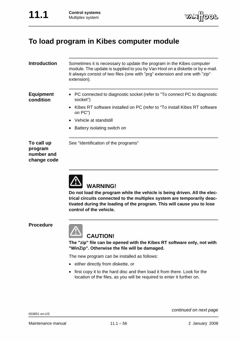
11.1 Control systemsMultiplex system
To load program in Kibes computer module
Introduction Sometimes it is necessary to update the program in the Kibes computer module. The update is supplied to you by Van Hool on a diskette or by e-mail. It always consist of two files (one with "prg" extension and one with "zip" extension).
Equipment condition
• PC connected to diagnostic socket (refer to "To connect PC to diagnostic socket")
• Kibes RT software installed on PC (refer to "To install Kibes RT software on PC")
• Vehicle at standstill
• Battery isolating switch on
To call up program number and change code
See "Identification of the programs"
WARNING!Do not load the program while the vehicle is being driven. All the elec-trical circuits connected to the multiplex system are temporarily deac-tivated during the loading of the program. This will cause you to lose control of the vehicle.
Procedure
CAUTION!The "zip" file can be opened with the Kibes RT software only, not with "WinZip". Otherwise the file will be damaged.
The new program can be installed as follows:
• either directly from diskette, or
• first copy it to the hard disc and then load it from there. Look for the location of the files, as you will be required to enter it further on.
003851 en-US
Maintenance manual 2 January 2008
continued on next page.
11.1 – 56
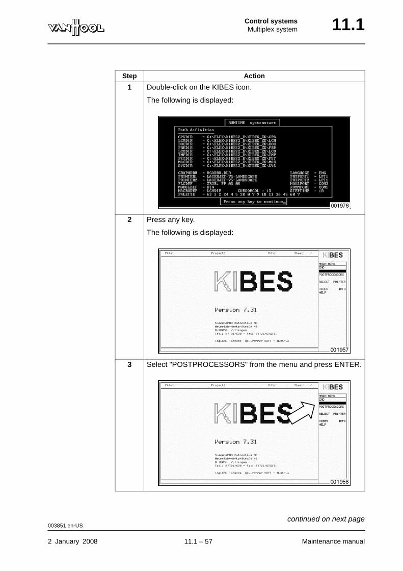
Control systemsMultiplex system 11.1
Step Action
1 Double-click on the KIBES icon.
The following is displayed:
2 Press any key.
The following is displayed:
3 Select "POSTPROCESSORS" from the menu and press ENTER.
003851 en-US
2 January 2008 Maintenance manual
continued on next page.
11.1 – 57
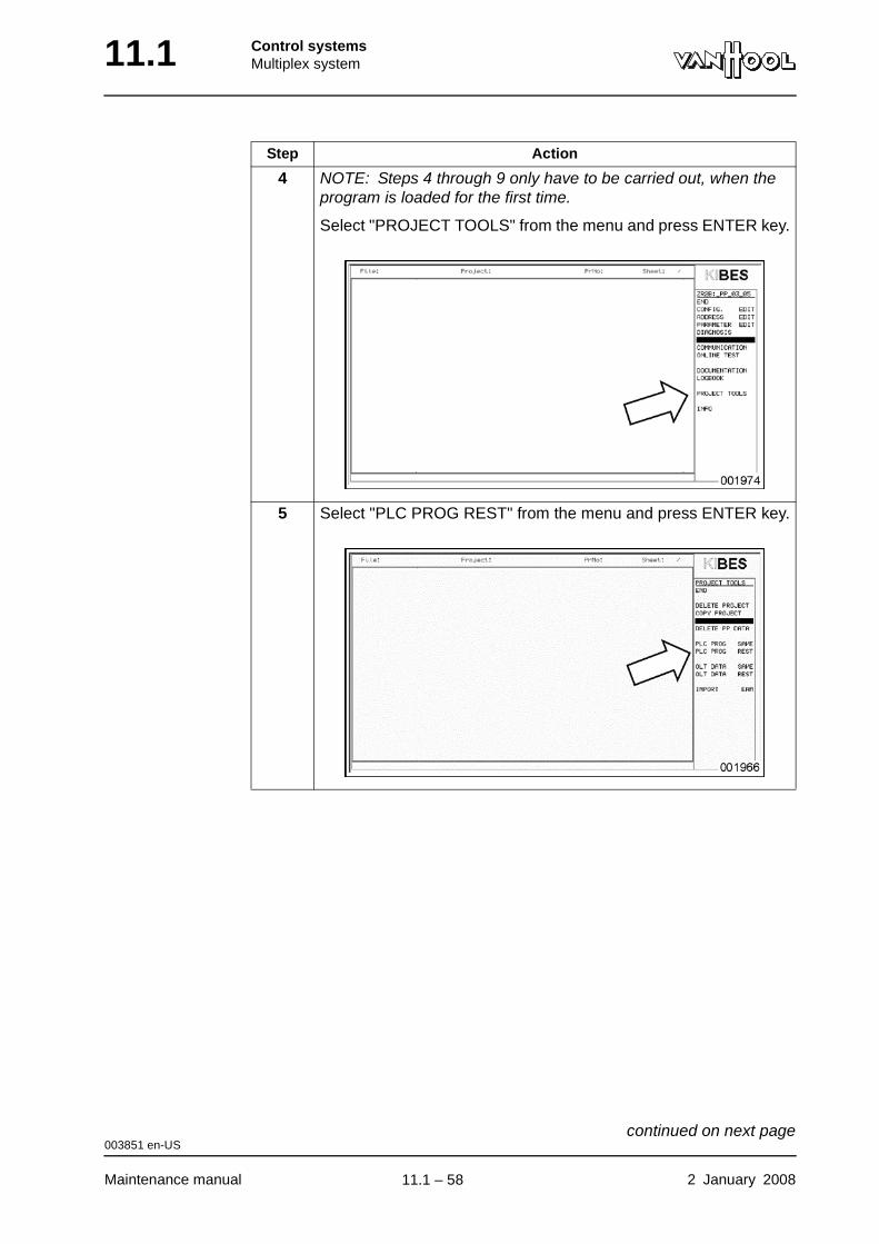
11.1 Control systemsMultiplex system
4 NOTE: Steps 4 through 9 only have to be carried out, when the program is loaded for the first time.
Select "PROJECT TOOLS" from the menu and press ENTER key.
5 Select "PLC PROG REST" from the menu and press ENTER key.
Step Action
003851 en-US
Maintenance manual 2 January 2008
continued on next page.
11.1 – 58
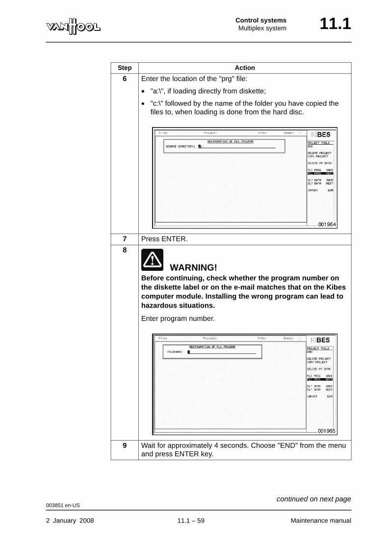
Control systemsMultiplex system 11.1
6 Enter the location of the "prg" file:
• "a:\", if loading directly from diskette;
• "c:\" followed by the name of the folder you have copied the files to, when loading is done from the hard disc.
7 Press ENTER.
8
WARNING!Before continuing, check whether the program number on the diskette label or on the e-mail matches that on the Kibes computer module. Installing the wrong program can lead to hazardous situations.
Enter program number.
9 Wait for approximately 4 seconds. Choose "END" from the menu and press ENTER key.
Step Action
003851 en-US
2 January 2008 Maintenance manual
continued on next page.
11.1 – 59
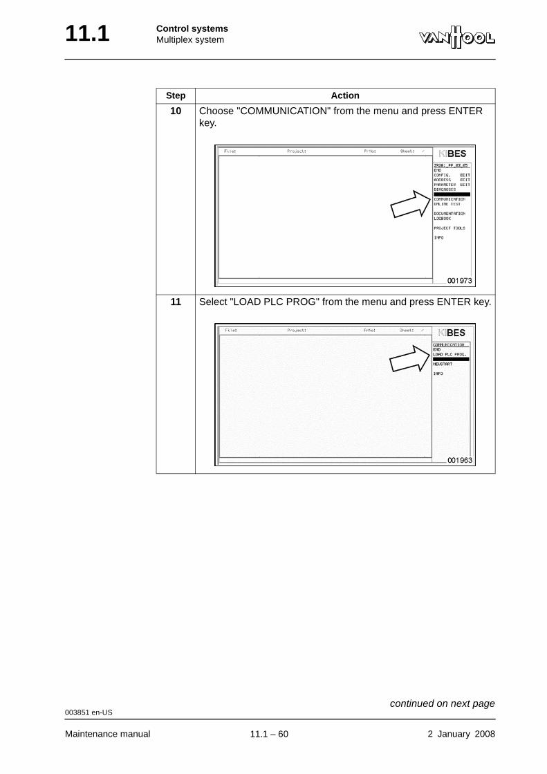
11.1 Control systemsMultiplex system
10 Choose "COMMUNICATION" from the menu and press ENTER key.
11 Select "LOAD PLC PROG" from the menu and press ENTER key.
Step Action
003851 en-US
Maintenance manual 2 January 2008
continued on next page.
11.1 – 60
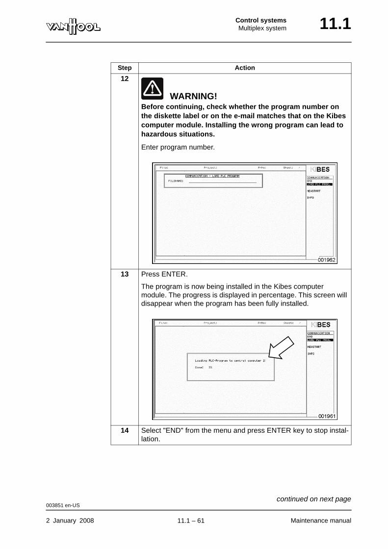
Control systemsMultiplex system 11.1
12
WARNING!Before continuing, check whether the program number on the diskette label or on the e-mail matches that on the Kibes computer module. Installing the wrong program can lead to hazardous situations.
Enter program number.
13 Press ENTER.
The program is now being installed in the Kibes computer module. The progress is displayed in percentage. This screen will disappear when the program has been fully installed.
14 Select "END" from the menu and press ENTER key to stop instal-lation.
Step Action
003851 en-US
2 January 2008 Maintenance manual
continued on next page.
11.1 – 61

11.1 Control systemsMultiplex system
15 On the Kibes computer module sticker, mark the change code you find on the diskette label or in the e-mail. The change code consists of one letter.
Step Action
003851 en-US
Maintenance manual 2 January 2008
.
11.1 – 62

Control systemsMultiplex system 11.1
To connect a PC to the diagnostic socket
Introduction You have to use a special adapter module to connect the PC to the vehicle diagnostic socket.
Special tools
PC system requirements
Figure: connection diagram
1 PC2 Adapter module K-Line V243 Vehicle diagnostic socket
Adapter module K-Line V24 Van Hool No. 10797942
Processor at least Intel 386 or equivalent
Internal memory at least 8 MB RAM
Conventional memory at least 580 kB
Graphic card EGA (640 x 350) or VGA (640 x 480)
Diskette drive 3.5”
Free space on hard disc at least 10 MB
Ports • serial port for mouse
• serial port (RS232) for connection to com-puter module ZR2-BD (Kibes)
Driver • DOS 5.0 or higher, or...
• Windows 95, 98, NT, 2000 or XP
000965 en-US
2 January 2008 Maintenance manual
.
11.1 – 63
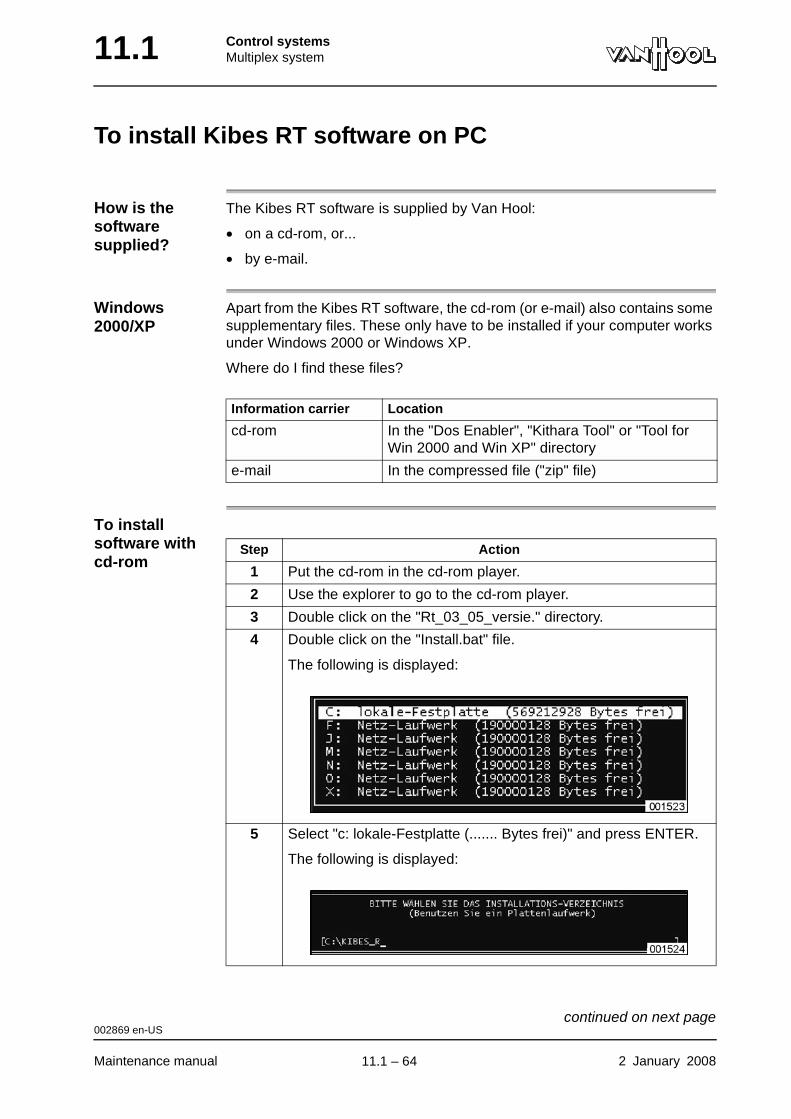
11.1 Control systemsMultiplex system
To install Kibes RT software on PC
How is the software supplied?
The Kibes RT software is supplied by Van Hool:
• on a cd-rom, or...
• by e-mail.
Windows 2000/XP
Apart from the Kibes RT software, the cd-rom (or e-mail) also contains some supplementary files. These only have to be installed if your computer works under Windows 2000 or Windows XP.
Where do I find these files?
To install software with cd-rom
Information carrier Location
cd-rom In the "Dos Enabler", "Kithara Tool" or "Tool for Win 2000 and Win XP" directory
e-mail In the compressed file ("zip" file)
Step Action
1 Put the cd-rom in the cd-rom player.
2 Use the explorer to go to the cd-rom player.
3 Double click on the "Rt_03_05_versie." directory.
4 Double click on the "Install.bat" file.
The following is displayed:
5 Select "c: lokale-Festplatte (....... Bytes frei)" and press ENTER.
The following is displayed:
002869 en-US
Maintenance manual 2 January 2008
continued on next page.
11.1 – 64
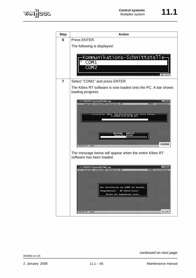
Control systemsMultiplex system 11.1
6 Press ENTER.
The following is displayed:
7 Select "COM1" and press ENTER.
The Kibes RT software is now loaded onto the PC. A bar shows loading progress.
The message below will appear when the entire Kibes RT software has been loaded.
Step Action
002869 en-US
2 January 2008 Maintenance manual
continued on next page.
11.1 – 65
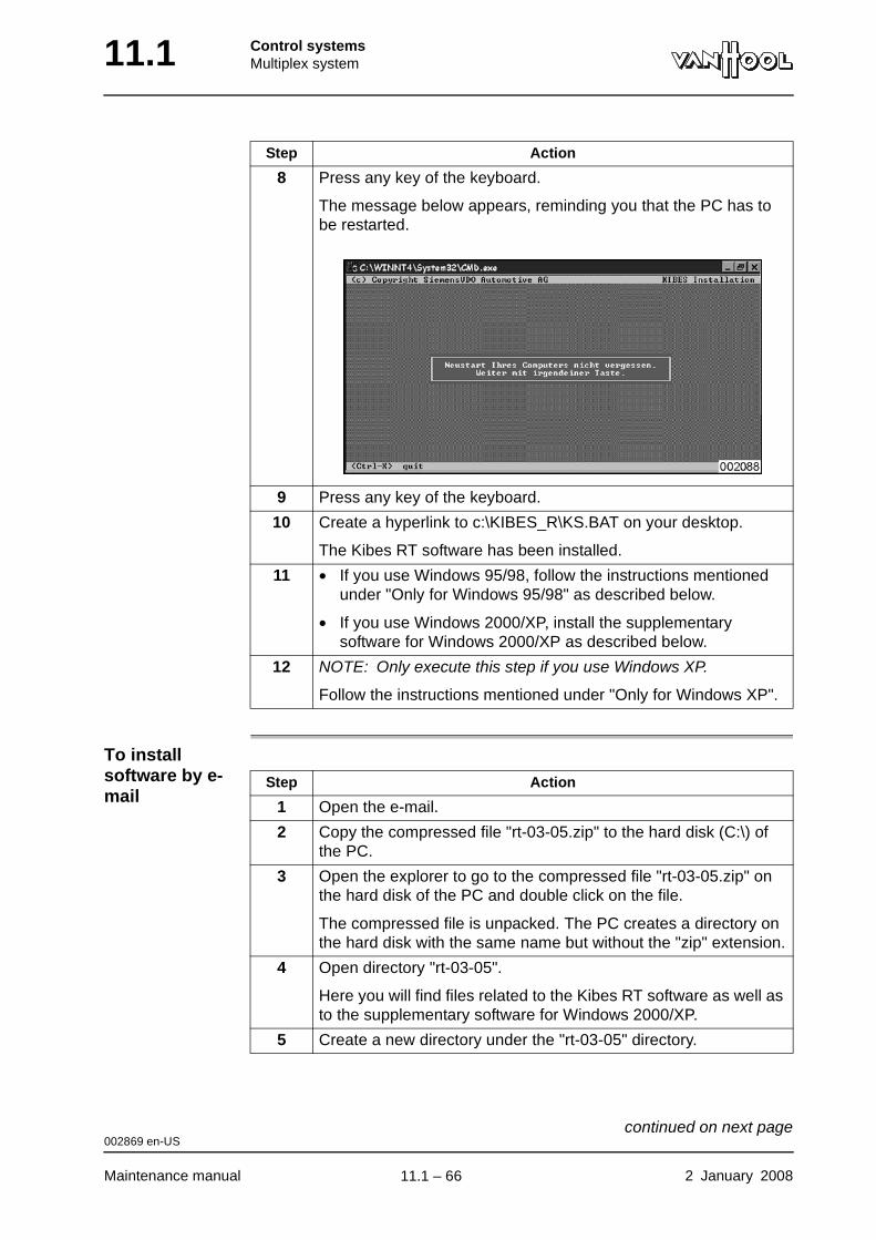
11.1 Control systemsMultiplex system
To install software by e-mail
8 Press any key of the keyboard.
The message below appears, reminding you that the PC has to be restarted.
9 Press any key of the keyboard.
10 Create a hyperlink to c:\KIBES_R\KS.BAT on your desktop.
The Kibes RT software has been installed.
11 • If you use Windows 95/98, follow the instructions mentioned under "Only for Windows 95/98" as described below.
• If you use Windows 2000/XP, install the supplementary software for Windows 2000/XP as described below.
12 NOTE: Only execute this step if you use Windows XP.
Follow the instructions mentioned under "Only for Windows XP".
Step Action
Step Action
1 Open the e-mail.
2 Copy the compressed file "rt-03-05.zip" to the hard disk (C:\) of the PC.
3 Open the explorer to go to the compressed file "rt-03-05.zip" on the hard disk of the PC and double click on the file.
The compressed file is unpacked. The PC creates a directory on the hard disk with the same name but without the "zip" extension.
4 Open directory "rt-03-05".
Here you will find files related to the Kibes RT software as well as to the supplementary software for Windows 2000/XP.
5 Create a new directory under the "rt-03-05" directory.
002869 en-US
Maintenance manual 2 January 2008
continued on next page.
11.1 – 66
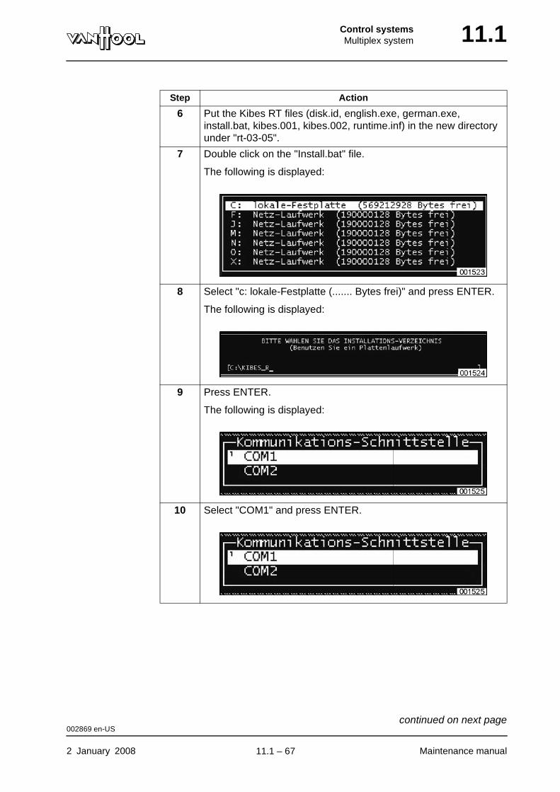
Control systemsMultiplex system 11.1
6 Put the Kibes RT files (disk.id, english.exe, german.exe, install.bat, kibes.001, kibes.002, runtime.inf) in the new directory under "rt-03-05".
7 Double click on the "Install.bat" file.
The following is displayed:
8 Select "c: lokale-Festplatte (....... Bytes frei)" and press ENTER.
The following is displayed:
9 Press ENTER.
The following is displayed:
10 Select "COM1" and press ENTER.
Step Action
002869 en-US
2 January 2008 Maintenance manual
continued on next page.
11.1 – 67
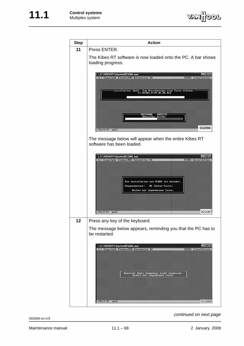
11.1 Control systemsMultiplex system
11 Press ENTER.
The Kibes RT software is now loaded onto the PC. A bar shows loading progress.
The message below will appear when the entire Kibes RT software has been loaded.
12 Press any key of the keyboard.
The message below appears, reminding you that the PC has to be restarted.
Step Action
002869 en-US
Maintenance manual 2 January 2008
continued on next page.
11.1 – 68
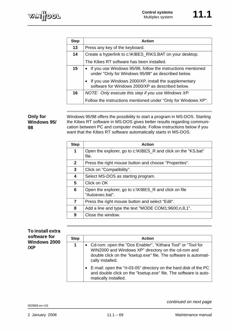
Control systemsMultiplex system 11.1
Only for Windows 95/98
Windows 95/98 offers the possibility to start a program in MS-DOS. Starting the Kibes RT software in MS-DOS gives better results regarding communi-cation between PC and computer module. Follow instructions below if you want that the Kibes RT software automatically starts in MS-DOS.
To install extra software for Windows 2000/XP
13 Press any key of the keyboard.
14 Create a hyperlink to c:\KIBES_R\KS.BAT on your desktop.
The Kibes RT software has been installed.
15 • If you use Windows 95/98, follow the instructions mentioned under "Only for Windows 95/98" as described below.
• If you use Windows 2000/XP, install the supplementary software for Windows 2000/XP as described below.
16 NOTE: Only execute this step if you use Windows XP.
Follow the instructions mentioned under "Only for Windows XP".
Step Action
Step Action
1 Open the explorer, go to c:\KIBES_R and click on the "KS.bat" file.
2 Press the right mouse button and choose "Properties".
3 Click on "Compatibility".
4 Select MS-DOS as starting program.
5 Click on OK
6 Open the explorer, go to c:\KIBES_R and click on file "Autoexec.bat".
7 Press the right mouse button and select "Edit".
8 Add a line and type the text "MODE COM1:9600,n,8,1".
9 Close the window.
Step Action
1 • Cd-rom: open the "Dos Enabler", "Kithara Tool" or "Tool for WIN2000 and Windows XP" directory on the cd-rom and double click on the "ksetup.exe" file. The software is automati-cally installed.
• E-mail: open the "rt-03-05" directory on the hard disk of the PC and double click on the "ksetup.exe" file. The software is auto-matically installed.
002869 en-US
2 January 2008 Maintenance manual
continued on next page.
11.1 – 69

11.1 Control systemsMultiplex system
Only for Windows XP
2 • Cd-rom: copy the "Ks-rt.bat" file from the "Dos Enabler", "Kithara Tool" or "Tool for WIN2000 and Windows XP" directory on the cd-rom to c:\kibes_r\.
• E-mail: copy the "Ks_rt.bat" file from the "rt-03-05" directory on the hard disk of the PC to c:\kibes_r\.
3 Open the explorer, go to c:\KIBES_R and click on the "KS.bat" file.
4 Press the right mouse button and select "Edit".
5 Remove the text "REM_" as indicated in the figure.
After the change, it looks like this:
6 Change the shortcut (to c:\Kibes_r\ks.bat) on your desktop with the shortcut to c:\Kibes_r\Ks_rt.bat.
7 Restart the PC to initialise the software.
Step Action
Step Action
1 Open the explorer and go to c:\KIBES_R.
2 Click on the "KS.bat" file.
3 Press the right mouse button and choose "Properties".
4 Click on the "Compatibility" button.
002869 en-US
Maintenance manual 2 January 2008
continued on next page.
11.1 – 70
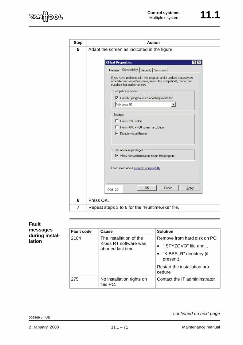
Control systemsMultiplex system 11.1
Fault messages during instal-lation
5 Adapt the screen as indicated in the figure.
6 Press OK.
7 Repeat steps 3 to 6 for the "Runtime.exe" file.
Step Action
Fault code Cause Solution
2104 The installation of the Kibes RT software was aborted last time.
Remove from hard disk on PC:
• "ISFYZQVO" file and...
• "KIBES_R" directory (if present).
Restart the installation pro-cedure
275 No installation rights on this PC.
Contact the IT admininstrator.
002869 en-US
2 January 2008 Maintenance manual
continued on next page.
11.1 – 71

11.1 Control systemsMultiplex system
To change language
You can choose between German, English or French as language on the screens.
Step Action
1 Open the explorer and go to c:\KIBES_R.
2 Double click on the "Runtime.sys" file.
3 Open the file in the scratch-pad program.
Below, behind "Language", you will find the abreviations "ENG", "GER" or "FRE". "ENG" stands for English, "GER" for German, "FRE" for French.
4 Select the text behind "Language" and type "ENG", "GER" or "FRE".
5 Close the scratch-pad program.
002869 en-US
Maintenance manual 2 January 2008
.
11.1 – 72
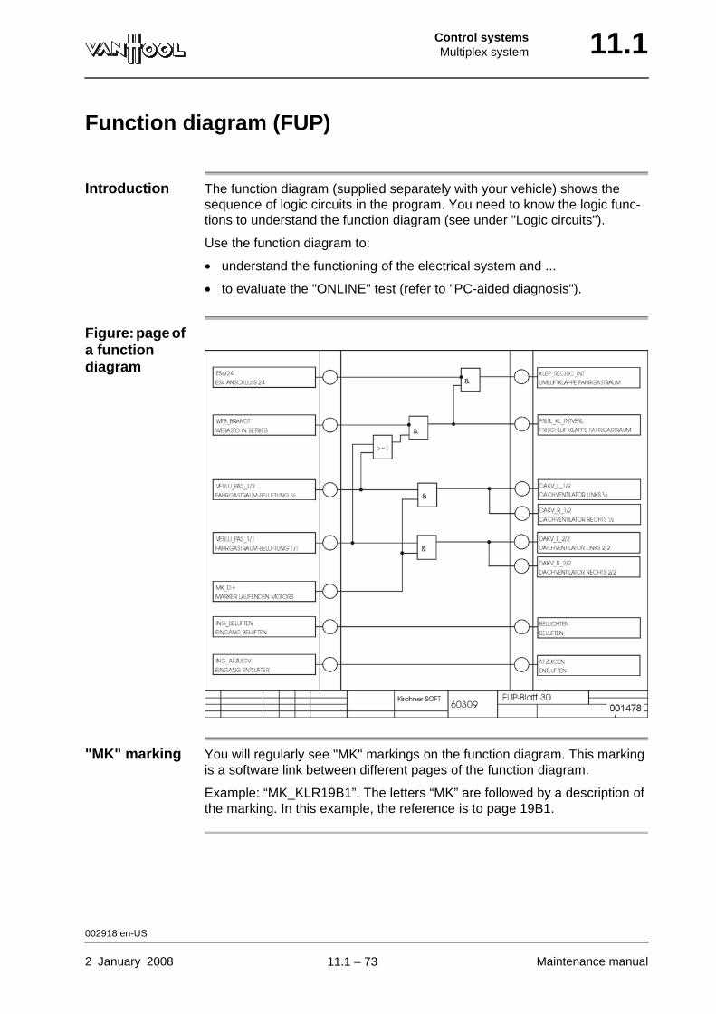
Control systemsMultiplex system 11.1
Function diagram (FUP)
Introduction The function diagram (supplied separately with your vehicle) shows the sequence of logic circuits in the program. You need to know the logic func-tions to understand the function diagram (see under "Logic circuits").
Use the function diagram to:
• understand the functioning of the electrical system and ...
• to evaluate the "ONLINE" test (refer to "PC-aided diagnosis").
Figure: page of a function diagram
"MK" marking You will regularly see "MK" markings on the function diagram. This marking is a software link between different pages of the function diagram.
Example: “MK_KLR19B1”. The letters “MK” are followed by a description of the marking. In this example, the reference is to page 19B1.
002918 en-US
2 January 2008 Maintenance manual
.
11.1 – 73
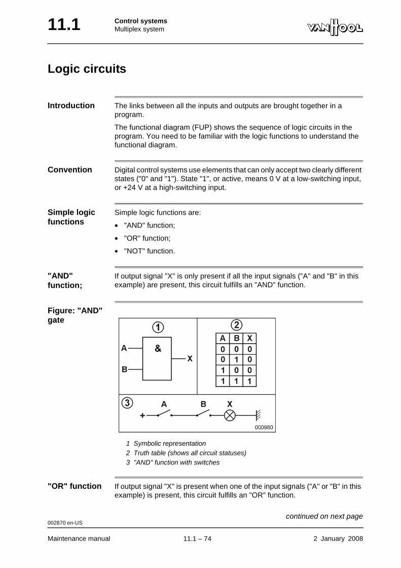
11.1 Control systemsMultiplex system
Logic circuits
Introduction The links between all the inputs and outputs are brought together in a program.
The functional diagram (FUP) shows the sequence of logic circuits in the program. You need to be familiar with the logic functions to understand the functional diagram.
Convention Digital control systems use elements that can only accept two clearly different states ("0" and "1"). State "1", or active, means 0 V at a low-switching input, or +24 V at a high-switching input.
Simple logic functions
Simple logic functions are:
• "AND" function;
• "OR" function;
• "NOT" function.
"AND" function;
If output signal "X" is only present if all the input signals ("A" and "B" in this example) are present, this circuit fulfills an "AND" function.
Figure: "AND" gate
1 Symbolic representation2 Truth table (shows all circuit statuses)3 "AND" function with switches
"OR" function If output signal "X" is present when one of the input signals ("A" or "B" in this example) is present, this circuit fulfills an "OR" function.
002870 en-US
Maintenance manual 2 January 2008
continued on next page.
11.1 – 74
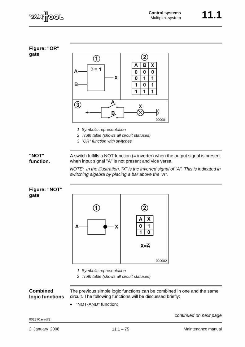
Control systemsMultiplex system 11.1
Figure: "OR" gate
1 Symbolic representation2 Truth table (shows all circuit statuses)3 "OR" function with switches
"NOT" function.
A switch fulfills a NOT function (= inverter) when the output signal is present when input signal "A" is not present and vice versa.
NOTE: In the illustration, "X" is the inverted signal of "A". This is indicated in switching algebra by placing a bar above the "A".
Figure: "NOT" gate
1 Symbolic representation2 Truth table (shows all circuit statuses)
Combined logic functions
The previous simple logic functions can be combined in one and the same circuit. The following functions will be discussed briefly:
• "NOT-AND" function;
002870 en-US
2 January 2008 Maintenance manual
continued on next page.
11.1 – 75
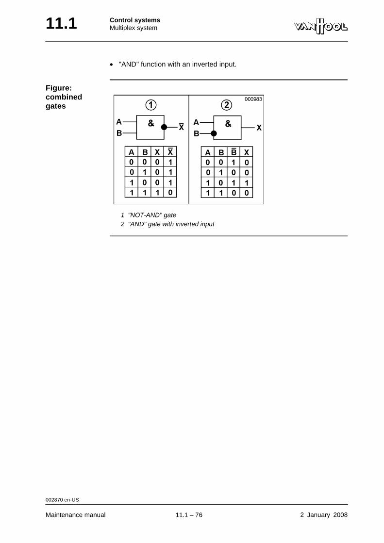
11.1 Control systemsMultiplex system
• "AND" function with an inverted input.
Figure: combined gates
1 "NOT-AND" gate2 "AND" gate with inverted input
002870 en-US
Maintenance manual 2 January 2008
.
11.1 – 76
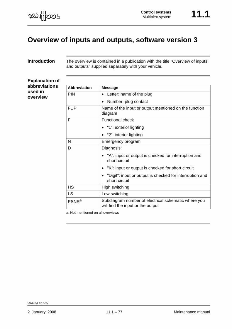
Control systemsMultiplex system 11.1
Overview of inputs and outputs, software version 3
Introduction The overview is contained in a publication with the title "Overview of inputs and outputs" supplied separately with your vehicle.
Explanation of abbreviations used in overview
Abbreviation Message
PIN • Letter: name of the plug
• Number: plug contact
FUP Name of the input or output mentioned on the function diagram
F Functional check
• “1”: exterior lighting
• “2”: interior lighting
N Emergency program
D Diagnosis:
• "A": input or output is checked for interruption and short circuit
• "K": input or output is checked for short circuit
• "Digit": input or output is checked for interruption and short circuit
HS High switching
LS Low switching
PSNRa
a. Not mentioned on all overviews
Subdiagram number of electrical schematic where you will find the input or the output
003983 en-US
2 January 2008 Maintenance manual
.
11.1 – 77

11.1 Control systemsMultiplex system
Special tools: multiplex system
Ordering number Description Figure
Van Hool 10797942 Adapter module K-Line V24
001820 en-US
Maintenance manual 2 January 2008
.
11.1 – 78
Control systemsATC 11.2
Chapter 2: ATC
Overview
Introduction This chapter deals with the ATC system.
Number of pages
8
Chapter publi-cation date
2 January 2008
Contents
Topic See page
Troubleshooting 11.2-2
Precaution in case of performance tests on roller brake tester
11.2-3
To measure resistance of ATC valve 11.2-5
Technical data: ATC system 11.2-7
2 January 2008 Maintenance manual
.
11.2 – 1
11.2 Control systemsATC
Troubleshooting
Cross-reference
Refer to chapter 5.2, "Control systems".
000735 en-US
Maintenance manual 2 January 2008
.
11.2 – 2
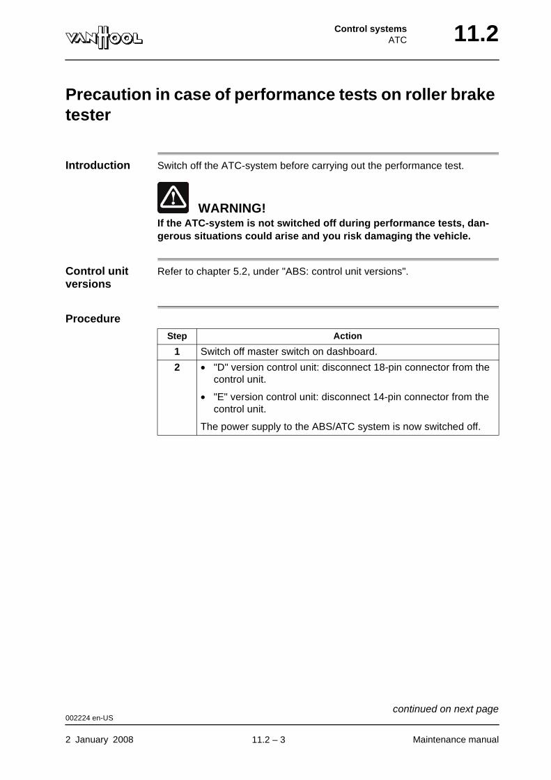
Control systemsATC 11.2
Precaution in case of performance tests on roller brake tester
Introduction Switch off the ATC-system before carrying out the performance test.
WARNING!If the ATC-system is not switched off during performance tests, dan-gerous situations could arise and you risk damaging the vehicle.
Control unit versions
Refer to chapter 5.2, under "ABS: control unit versions".
Procedure
Step Action
1 Switch off master switch on dashboard.
2 • "D" version control unit: disconnect 18-pin connector from the control unit.
• "E" version control unit: disconnect 14-pin connector from the control unit.
The power supply to the ABS/ATC system is now switched off.
002224 en-US
2 January 2008 Maintenance manual
continued on next page.
11.2 – 3
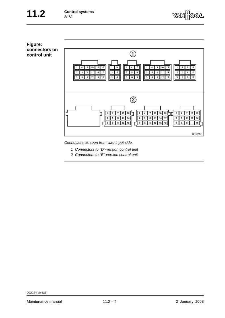
11.2 Control systemsATC
Figure: connectors on control unit
Connectors as seen from wire input side.
1 Connectors to "D"-version control unit2 Connectors to "E"-version control unit
002224 en-US
Maintenance manual 2 January 2008
.
11.2 – 4
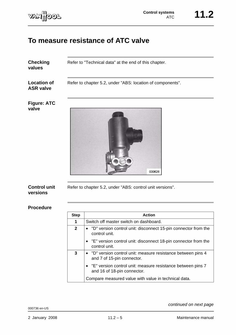
Control systemsATC 11.2
To measure resistance of ATC valve
Checking values
Refer to "Technical data" at the end of this chapter.
Location of ASR valve
Refer to chapter 5.2, under "ABS: location of components".
Figure: ATC valve
Control unit versions
Refer to chapter 5.2, under "ABS: control unit versions".
Procedure
Step Action
1 Switch off master switch on dashboard.
2 • "D" version control unit: disconnect 15-pin connector from the control unit.
• "E" version control unit: disconnect 18-pin connector from the control unit.
3 • "D" version control unit: measure resistance between pins 4 and 7 of 15-pin connector.
• "E" version control unit: measure resistance between pins 7 and 16 of 18-pin connector.
Compare measured value with value in technical data.
000736 en-US
2 January 2008 Maintenance manual
continued on next page.
11.2 – 5
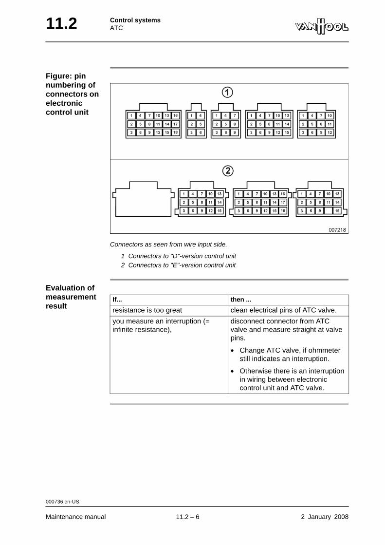
11.2 Control systemsATC
Figure: pin numbering of connectors on electronic control unit
Connectors as seen from wire input side.
1 Connectors to "D"-version control unit2 Connectors to "E"-version control unit
Evaluation of measurement result
If... then ...
resistance is too great clean electrical pins of ATC valve.
you measure an interruption (= infinite resistance),
disconnect connector from ATC valve and measure straight at valve pins.
• Change ATC valve, if ohmmeter still indicates an interruption.
• Otherwise there is an interruption in wiring between electronic control unit and ATC valve.
000736 en-US
Maintenance manual 2 January 2008
.
11.2 – 6

Control systemsATC 11.2
Technical data: ATC system
ATC valve
Electrical resistance 26.3 to 49.0 ohms
000783 en-US
2 January 2008 Maintenance manual
.
11.2 – 7
11.2 Control systemsATC
This page has been intentionally left blank.
000783 en-US
Maintenance manual 2 January 200811.2 – 8
Part 12 - Axles
Overview
Contents
Chapter See page
Chapter 6: Front axle 12.6-1
Chapter 10: Drive axle 12.10-1
Chapter 14: Trailing axle 12.14-1

AxlesFront axle 12.6
Chapter 6: Front axle
Overview
Introduction This chapter deals with the front axle.
Number of pages
38
Chapter publi-cation date
2 January 2008
Contents
Topic See page
Geometry 12.6-2
To check/adjust toe 12.6-3
To check/adjust steering lock angles 12.6-5
To remove axle half 12.6-6
To install axle half 12.6-8
To check security of control arms 12.6-10
To replace control arm 12.6-11
To remove rubber bushings of control arm 12.6-12
To install rubber bushings of control arm 12.6-14
To replace flexible ball joint of control arm 12.6-17
To adjust length of control arms tie-rod 12.6-19
To check wheel bearing end-play 12.6-21
To remove wheel hub 12.6-22
To install wheel hub 12.6-26
To grease king-pin bearings 12.6-30
To check play between steering knuckle and axle center 12.6-31
Technical data: front axle 12.6-33
Special tools: front axle 12.6-35
Front axle, exploded view 12.6-36
2 January 2008 Maintenance manual
.
12.6 – 1
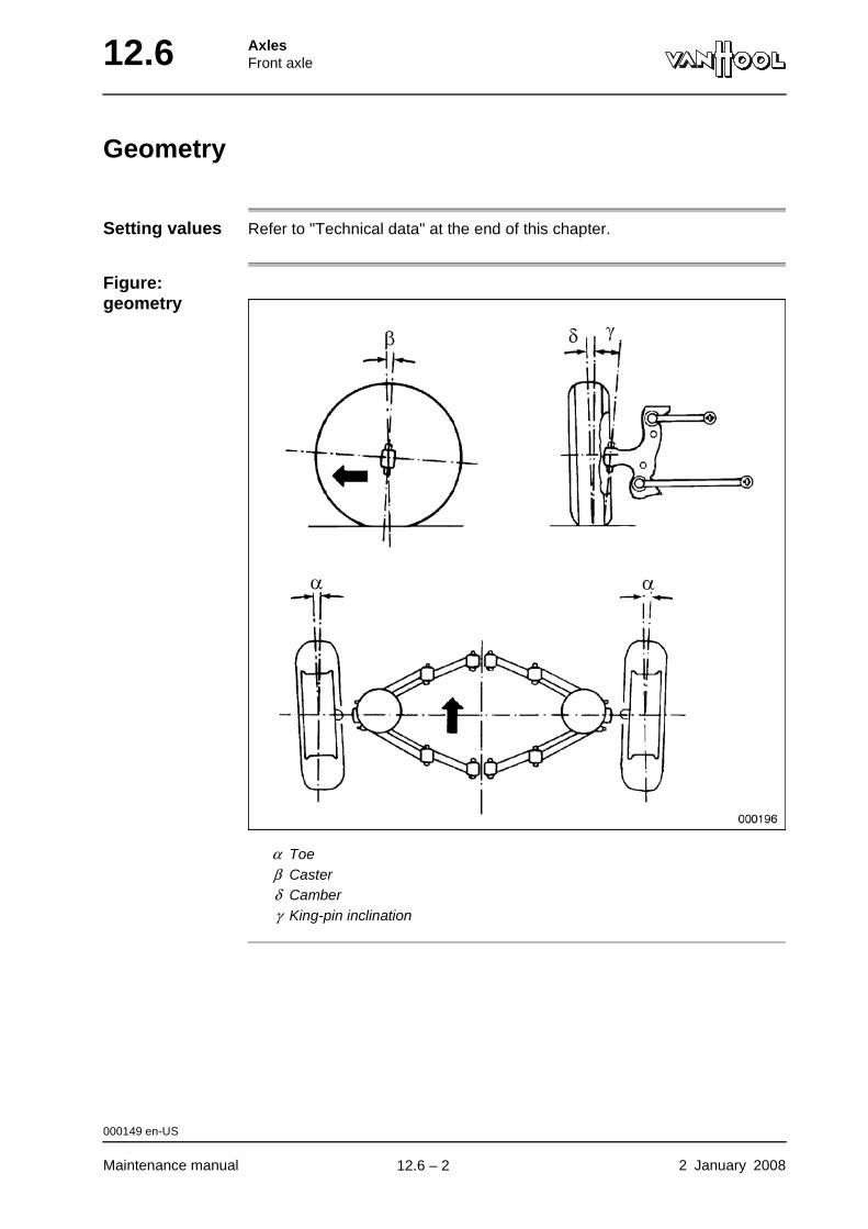
12.6 AxlesFront axle
Geometry
Setting values Refer to "Technical data" at the end of this chapter.
Figure: geometry
α Toeβ Casterδ Camberγ King-pin inclination
000149 en-US
Maintenance manual 2 January 2008
.
12.6 – 2
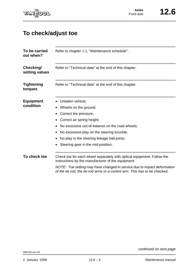
AxlesFront axle 12.6
To check/adjust toe
To be carried out when?
Refer to chapter 1.1, "Maintenance schedule".
Checking/setting values
Refer to "Technical data" at the end of this chapter.
Tightening torques
Refer to "Technical data" at the end of this chapter.
Equipment condition
• Unladen vehicle;
• Wheels on the ground;
• Correct tire pressure;
• Correct air spring height;
• No excessive out-of-balance on the road wheels;
• No excessive play on the steering knuckle;
• No play in the steering linkage ball-joints;
• Steering gear in the mid-position.
To check toe Check toe for each wheel separately with optical equipment. Follow the instructions by the manufacturer of the equipment.
NOTE: Toe setting may have changed in service due to impact deformation of the tie rod, the tie-rod arms or a control arm. This has to be checked.
000150 en-US
2 January 2008 Maintenance manual
continued on next page.
12.6 – 3

12.6 AxlesFront axle
Figure: tie-rod end
1 Clamping bolt
To adjust toe You can adjust the toe by altering the effective length of the tie rod of the wheel.
Step Action
1 Loosen the clamping bolts of the rod ends.
2 Rotate tie-rod tube in appropriate direction.
3 Install new self-locking nuts on the clamping bolts. Tighten the nuts to the prescribed torque.
4 Recheck toe.
000150 en-US
Maintenance manual 2 January 2008
.
12.6 – 4
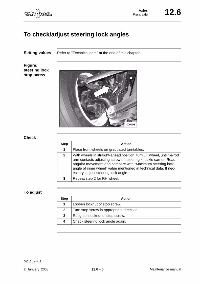
AxlesFront axle 12.6
To check/adjust steering lock angles
Setting values Refer to "Technical data" at the end of this chapter.
Figure: steering lock stop-screw
Check
To adjust
Step Action
1 Place front wheels on graduated turntables.
2 With wheels in straight-ahead position, turn LH wheel, until tie-rod arm contacts adjusting screw on steering knuckle carrier. Read angular movement and compare with "Maximum steering lock angle of inner wheel" value mentioned in technical data. If nec-essary, adjust steering lock angle.
3 Repeat step 2 for RH wheel.
Step Action
1 Loosen locknut of stop screw.
2 Turn stop screw in appropriate direction.
3 Retighten locknut of stop screw.
4 Check steering lock angle again.
000151 en-US
2 January 2008 Maintenance manual
.
12.6 – 5

12.6 AxlesFront axle
To remove axle half
WARNING!Ensure that the axle half is well supported before you loosen the fixing bolts.
Procedure
Step Action
1 Apply the parking brake and place chocks in front of and behind the wheels of the drive axle.
2 Fully deplete the air suspension by means of the drain valve on the auxiliaries tank.
3 Slacken the wheel nuts on the side of the axle half that is to be removed, by half a turn.
4 Put two jacks under the chassis. Raise the vehicle until the front wheels clear the ground. Support the chassis with axle stands or wooden blocks.
5 Mark the position of the wheel in relation to the hub (these parts are balanced together). Remove wheel.
6 Loosen the vertical rod of the leveling valve on the bottom at the right axle half side. Pull the vertical rod downward to release the air from the air bags.
7 Roll a lifting device under the axle half.
8 Depressurize the brake system. Disconnect the compressed-air hose from the brake chamber.
9 Disconnect shock absorber from the steering knuckle carrier.
000140 en-US
Maintenance manual 2 January 2008
continued on next page.
12.6 – 6

AxlesFront axle 12.6
10 Remove the screws that secure the air bag piston to the steering knuckle carrier.
11 Disconnect the tie rod from the tie-rod arm.
12 NOTE: Make note of the number and the position of the camber adjustment shims, for re-use during assembly.
Remove the nuts of the four bolts securing the upper control arms to the chassis, then remove the four nuts of the lower control arms. To keep the opposite axle half in place, reinstall the fixing bolts and nuts of the lower control arms.
13 Withdraw the axle half from the vehicle.
Step Action
000140 en-US
2 January 2008 Maintenance manual
.
12.6 – 7
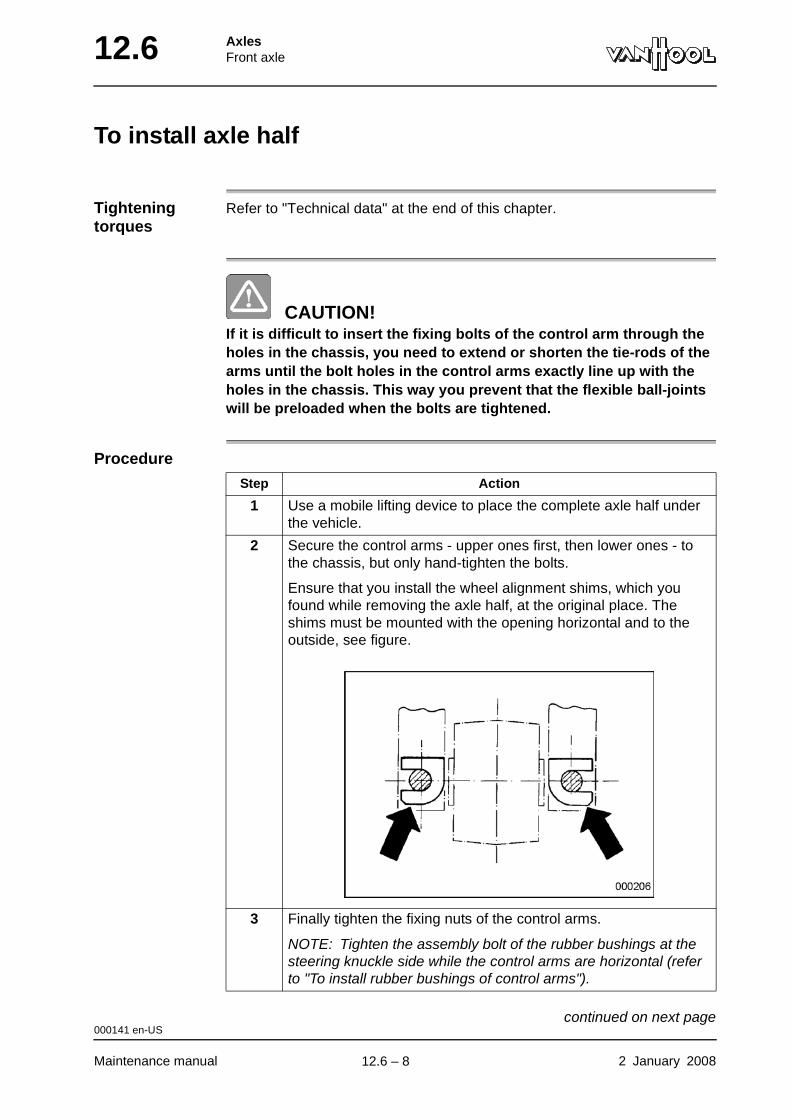
12.6 AxlesFront axle
To install axle half
Tightening torques
Refer to "Technical data" at the end of this chapter.
CAUTION!If it is difficult to insert the fixing bolts of the control arm through the holes in the chassis, you need to extend or shorten the tie-rods of the arms until the bolt holes in the control arms exactly line up with the holes in the chassis. This way you prevent that the flexible ball-joints will be preloaded when the bolts are tightened.
Procedure
Step Action
1 Use a mobile lifting device to place the complete axle half under the vehicle.
2 Secure the control arms - upper ones first, then lower ones - to the chassis, but only hand-tighten the bolts.
Ensure that you install the wheel alignment shims, which you found while removing the axle half, at the original place. The shims must be mounted with the opening horizontal and to the outside, see figure.
3 Finally tighten the fixing nuts of the control arms.
NOTE: Tighten the assembly bolt of the rubber bushings at the steering knuckle side while the control arms are horizontal (refer to "To install rubber bushings of control arms").
000141 en-US
Maintenance manual 2 January 2008
continued on next page.
12.6 – 8
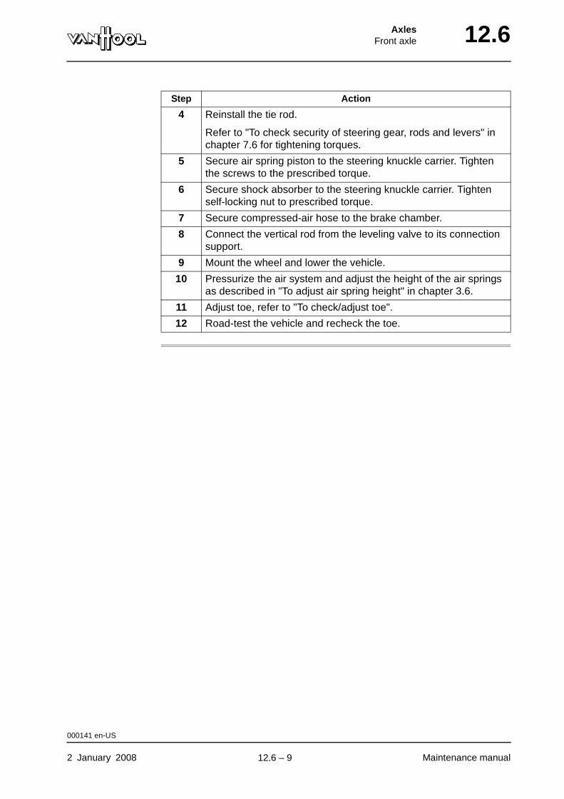
AxlesFront axle 12.6
4 Reinstall the tie rod.
Refer to "To check security of steering gear, rods and levers" in chapter 7.6 for tightening torques.
5 Secure air spring piston to the steering knuckle carrier. Tighten the screws to the prescribed torque.
6 Secure shock absorber to the steering knuckle carrier. Tighten self-locking nut to prescribed torque.
7 Secure compressed-air hose to the brake chamber.
8 Connect the vertical rod from the leveling valve to its connection support.
9 Mount the wheel and lower the vehicle.
10 Pressurize the air system and adjust the height of the air springs as described in "To adjust air spring height" in chapter 3.6.
11 Adjust toe, refer to "To check/adjust toe".
12 Road-test the vehicle and recheck the toe.
Step Action
000141 en-US
2 January 2008 Maintenance manual
.
12.6 – 9
12.6 AxlesFront axle
To check security of control arms
Tightening torques
Refer to "Technical data" at the end of this chapter.
Procedure Visually check those bolts, screws and nuts that are locked by means of a cotter pin, a locking plate or locking adhesive (Loctite). The security of all others must be checked mechanically. Retighten, if necessary.
WARNING!Never retighten bolts, screws or nuts that are fitted with locking adhesive, as this would destroy locking properties.
000795 en-US
Maintenance manual 2 January 2008
.
12.6 – 10
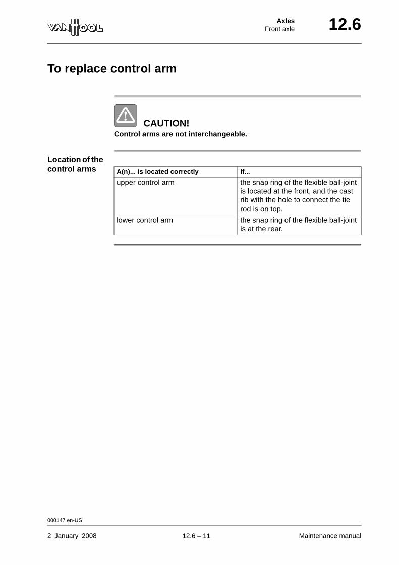
AxlesFront axle 12.6
To replace control arm
CAUTION!Control arms are not interchangeable.
Location of the control arms A(n)... is located correctly If...
upper control arm the snap ring of the flexible ball-joint is located at the front, and the cast rib with the hole to connect the tie rod is on top.
lower control arm the snap ring of the flexible ball-joint is at the rear.
000147 en-US
2 January 2008 Maintenance manual
.
12.6 – 11
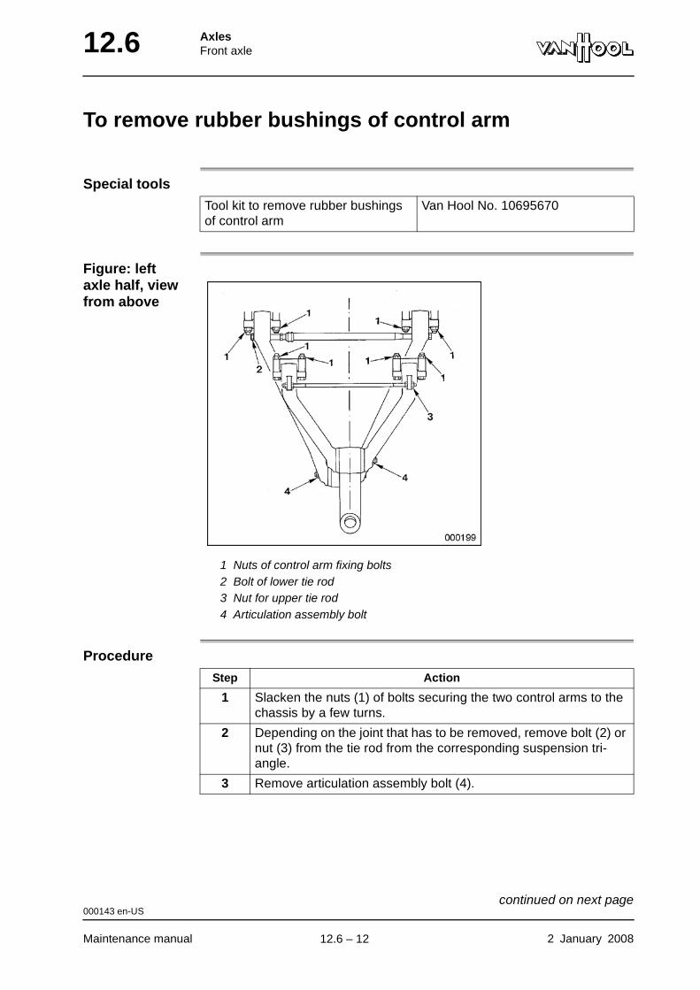
12.6 AxlesFront axle
To remove rubber bushings of control arm
Special tools
Figure: left axle half, view from above
1 Nuts of control arm fixing bolts2 Bolt of lower tie rod3 Nut for upper tie rod4 Articulation assembly bolt
Procedure
Tool kit to remove rubber bushings of control arm
Van Hool No. 10695670
Step Action
1 Slacken the nuts (1) of bolts securing the two control arms to the chassis by a few turns.
2 Depending on the joint that has to be removed, remove bolt (2) or nut (3) from the tie rod from the corresponding suspension tri-angle.
3 Remove articulation assembly bolt (4).
000143 en-US
Maintenance manual 2 January 2008
continued on next page.
12.6 – 12
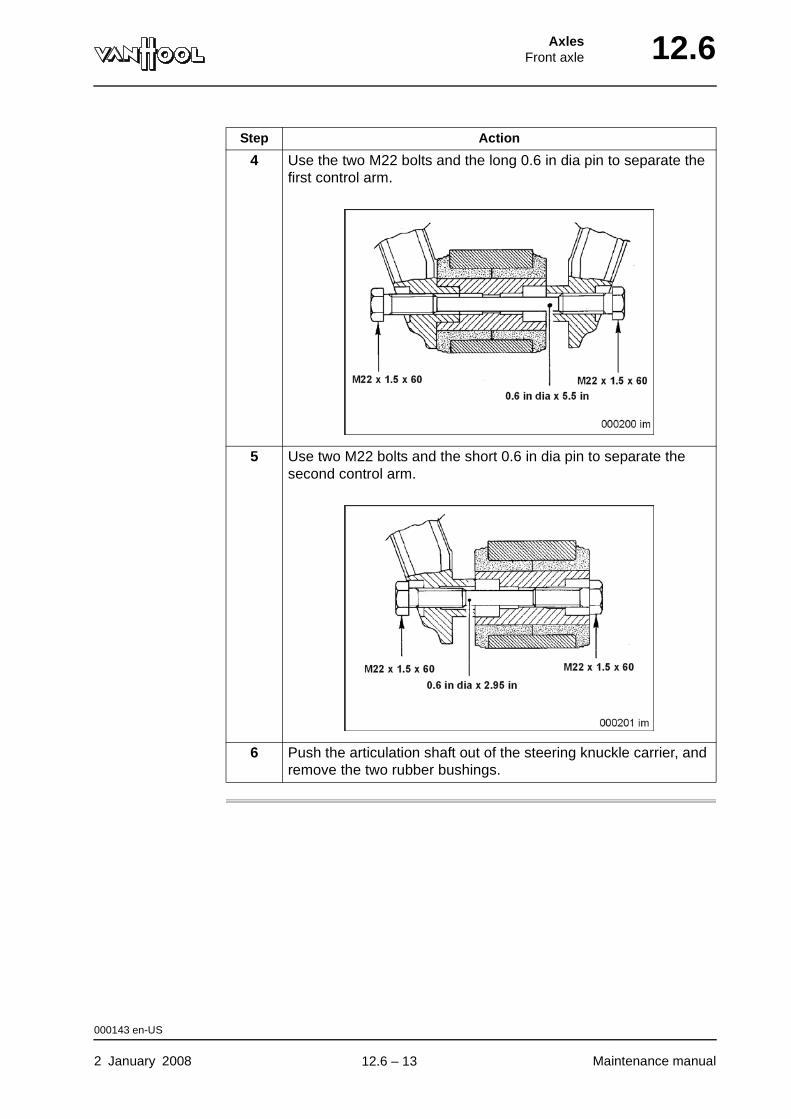
AxlesFront axle 12.6
4 Use the two M22 bolts and the long 0.6 in dia pin to separate the first control arm.
5 Use two M22 bolts and the short 0.6 in dia pin to separate the second control arm.
6 Push the articulation shaft out of the steering knuckle carrier, and remove the two rubber bushings.
Step Action
000143 en-US
2 January 2008 Maintenance manual
.
12.6 – 13
12.6 AxlesFront axle
To install rubber bushings of control arm
Consumables
Tightening torques
Refer to "Technical data" at the end of this chapter.
Rubber bushing Van Hool No. 624317270
Nut of assembly bolt Van Hool No. 660207287
004154 en-US
Maintenance manual 2 January 2008
continued on next page.
12.6 – 14
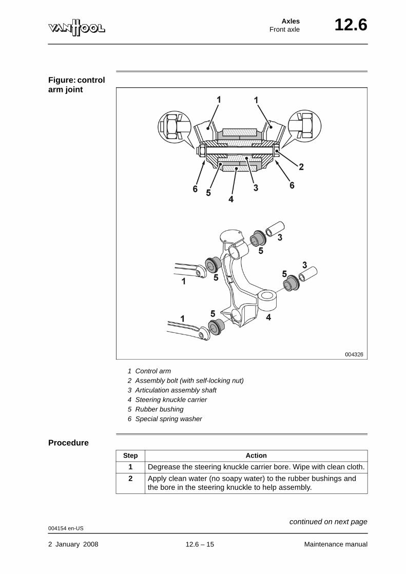
AxlesFront axle 12.6
Figure: control arm joint
1 Control arm2 Assembly bolt (with self-locking nut)3 Articulation assembly shaft4 Steering knuckle carrier5 Rubber bushing6 Special spring washer
Procedure
Step Action
1 Degrease the steering knuckle carrier bore. Wipe with clean cloth.
2 Apply clean water (no soapy water) to the rubber bushings and the bore in the steering knuckle to help assembly.
004154 en-US
2 January 2008 Maintenance manual
continued on next page.
12.6 – 15
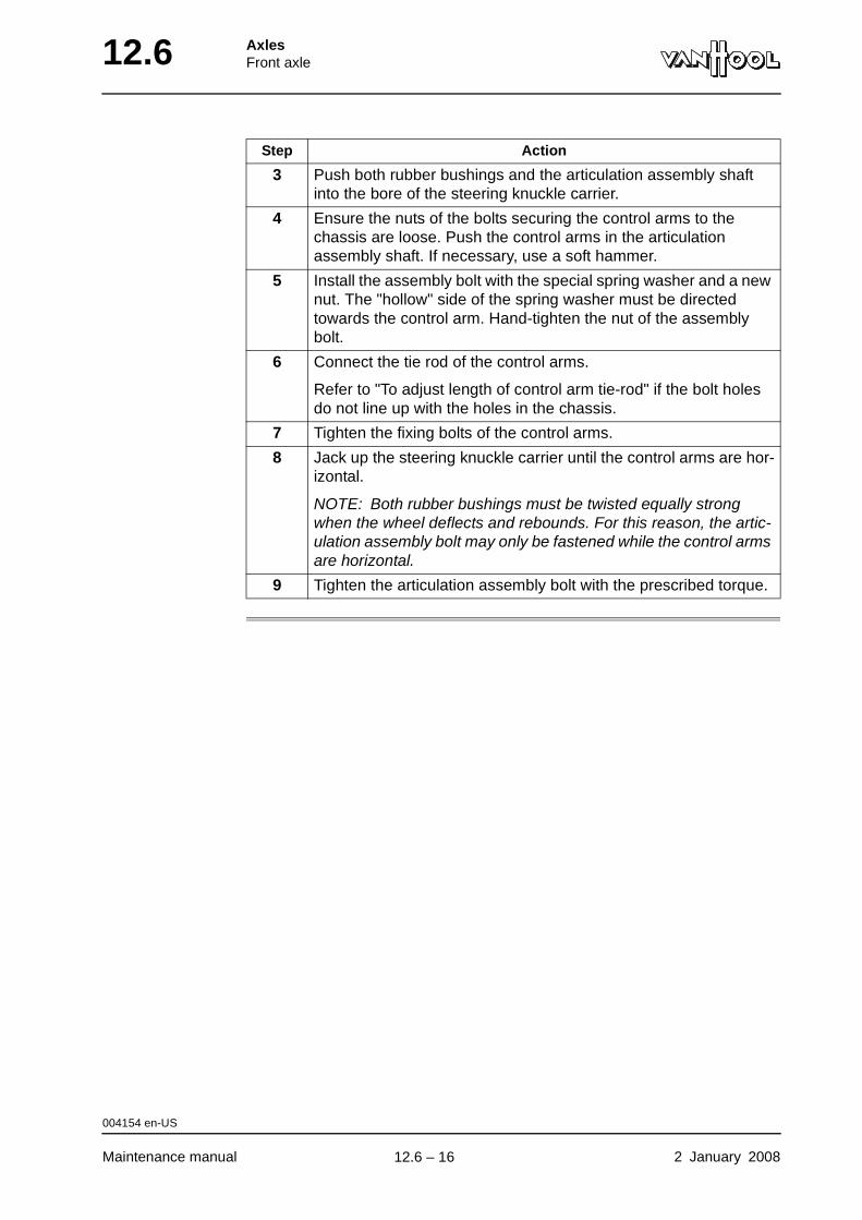
12.6 AxlesFront axle
3 Push both rubber bushings and the articulation assembly shaft into the bore of the steering knuckle carrier.
4 Ensure the nuts of the bolts securing the control arms to the chassis are loose. Push the control arms in the articulation assembly shaft. If necessary, use a soft hammer.
5 Install the assembly bolt with the special spring washer and a new nut. The "hollow" side of the spring washer must be directed towards the control arm. Hand-tighten the nut of the assembly bolt.
6 Connect the tie rod of the control arms.
Refer to "To adjust length of control arm tie-rod" if the bolt holes do not line up with the holes in the chassis.
7 Tighten the fixing bolts of the control arms.
8 Jack up the steering knuckle carrier until the control arms are hor-izontal.
NOTE: Both rubber bushings must be twisted equally strong when the wheel deflects and rebounds. For this reason, the artic-ulation assembly bolt may only be fastened while the control arms are horizontal.
9 Tighten the articulation assembly bolt with the prescribed torque.
Step Action
004154 en-US
Maintenance manual 2 January 2008
.
12.6 – 16
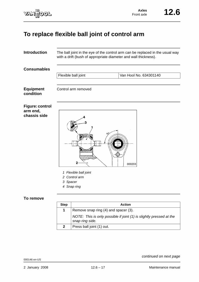
AxlesFront axle 12.6
To replace flexible ball joint of control arm
Introduction The ball joint in the eye of the control arm can be replaced in the usual way with a drift (bush of appropriate diameter and wall thickness).
Consumables
Equipment condition
Control arm removed
Figure: control arm end, chassis side
1 Flexible ball joint2 Control arm3 Spacer4 Snap ring
To remove
Flexible ball joint Van Hool No. 634301140
Step Action
1 Remove snap ring (4) and spacer (3).
NOTE: This is only possible if joint (1) is slightly pressed at the snap ring side.
2 Press ball joint (1) out.
000146 en-US
2 January 2008 Maintenance manual
continued on next page.
12.6 – 17
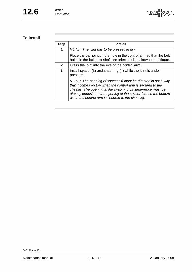
12.6 AxlesFront axle
To install
Step Action
1 NOTE: The joint has to be pressed in dry.
Place the ball joint on the hole in the control arm so that the bolt holes in the ball-joint shaft are orientated as shown in the figure.
2 Press the joint into the eye of the control arm.
3 Install spacer (3) and snap ring (4) while the joint is under pressure.
NOTE: The opening of spacer (3) must be directed in such way that it comes on top when the control arm is secured to the chassis. The opening in the snap ring circumference must be directly opposite to the opening of the spacer (i.e. on the bottom when the control arm is secured to the chassis).
000146 en-US
Maintenance manual 2 January 2008
.
12.6 – 18
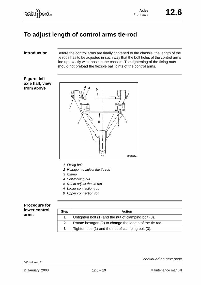
AxlesFront axle 12.6
To adjust length of control arms tie-rod
Introduction Before the control arms are finally tightened to the chassis, the length of the tie rods has to be adjusted in such way that the bolt holes of the control arms line up exactly with those in the chassis. The tightening of the fixing nuts should not preload the flexible ball joints of the control arms.
Figure: left axle half, view from above
1 Fixing bolt2 Hexagon to adjust the tie rod3 Clamp4 Self-locking nut5 Nut to adjust the tie rodA Lower connection rodB Upper connection rod
Procedure for lower control arms
Step Action
1 Untighten bolt (1) and the nut of clamping bolt (3).
2 Rotate hexagon (2) to change the length of the tie rod.
3 Tighten bolt (1) and the nut of clamping bolt (3).
000148 en-US
2 January 2008 Maintenance manual
continued on next page.
12.6 – 19
12.6 AxlesFront axle
Procedure for upper control arms
Step Action
1 Loosen nuts (4).
2 Rotate nuts (5) to change the length of the tie rod.
3 Tighten nuts (4).
000148 en-US
Maintenance manual 2 January 2008
.
12.6 – 20
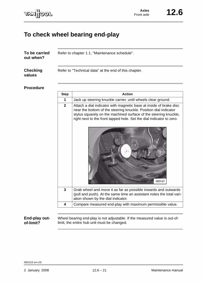
AxlesFront axle 12.6
To check wheel bearing end-play
To be carried out when?
Refer to chapter 1.1, "Maintenance schedule".
Checking values
Refer to "Technical data" at the end of this chapter.
Procedure
End-play out-of-limit?
Wheel bearing end-play is not adjustable. If the measured value is out-of-limit, the entire hub unit must be changed.
Step Action
1 Jack up steering knuckle carrier, until wheels clear ground.
2 Attach a dial indicator with magnetic base at inside of brake disc near the bottom of the steering knuckle. Position dial indicator stylus squarely on the machined surface of the steering knuckle, right next to the front tapped hole. Set the dial indicator to zero.
3 Grab wheel and move it as far as possible inwards and outwards (pull and push). At the same time an assistant notes the total vari-ation shown by the dial indicator.
4 Compare measured end-play with maximum permissible value.
000153 en-US
2 January 2008 Maintenance manual
.
12.6 – 21
12.6 AxlesFront axle
To remove wheel hub
Special tools
Equipment condition
• Parking brake applied
• Wheels remaining on the ground chocked
• Vehicle jacked up at the front
• Road wheel removed
• Brake caliper/brake carrier removed, refer to "To remove brake caliper/brake carrier" in chapter 5.10.
Hub nut wrench Van Hool No. A996030253
Tool set to remove hub unit from steering knuckle spindle
• Spindle
• Flange
• Threaded bush
• Cover
• Van Hool No. A996060240
• Van Hool No. A996060464
• Van Hool No. A996060251
• Van Hool No. A996060238
000155 en-US
Maintenance manual 2 January 2008
continued on next page.
12.6 – 22
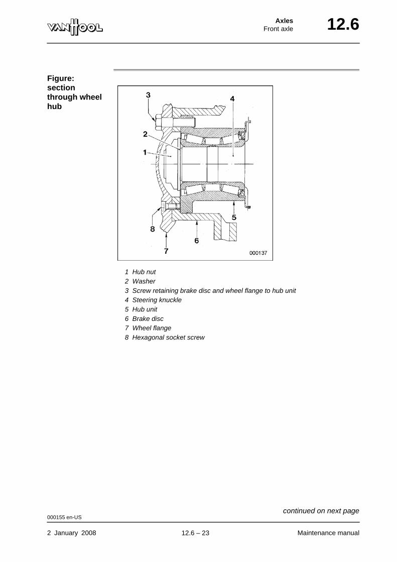
AxlesFront axle 12.6
Figure: section through wheel hub
1 Hub nut2 Washer3 Screw retaining brake disc and wheel flange to hub unit4 Steering knuckle5 Hub unit6 Brake disc7 Wheel flange8 Hexagonal socket screw
000155 en-US
2 January 2008 Maintenance manual
continued on next page.
12.6 – 23
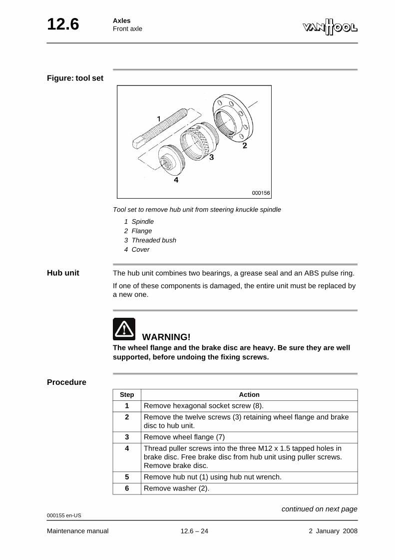
12.6 AxlesFront axle
Figure: tool set
Tool set to remove hub unit from steering knuckle spindle
1 Spindle2 Flange3 Threaded bush4 Cover
Hub unit The hub unit combines two bearings, a grease seal and an ABS pulse ring.
If one of these components is damaged, the entire unit must be replaced by a new one.
WARNING!The wheel flange and the brake disc are heavy. Be sure they are well supported, before undoing the fixing screws.
Procedure
Step Action
1 Remove hexagonal socket screw (8).
2 Remove the twelve screws (3) retaining wheel flange and brake disc to hub unit.
3 Remove wheel flange (7)
4 Thread puller screws into the three M12 x 1.5 tapped holes in brake disc. Free brake disc from hub unit using puller screws. Remove brake disc.
5 Remove hub nut (1) using hub nut wrench.
6 Remove washer (2).
000155 en-US
Maintenance manual 2 January 2008
continued on next page.
12.6 – 24
AxlesFront axle 12.6
7 Secure flange (2) of tool set to hub unit with three screws.
8 Screw threaded bush (3) of tool set into flange (2).
9 Screw cover (4) of tool set into threaded bush (3).
10 Screw spindle (1) of tool set into cover (4).
11 Remove hub unit by turning spindle (1) of tool set clockwise.
Step Action
000155 en-US
2 January 2008 Maintenance manual
.
12.6 – 25
12.6 AxlesFront axle
To install wheel hub
Consumables
Special tools
Tightening torques
Refer to "Technical data" at the end of this chapter.
Hub unit Van Hool No. 10599854
Hub nut Van Hool No. 10554144
Tool set to install the hub unit on the steering knuckle spindle
Van Hool No. 10678700
000157 en-US
Maintenance manual 2 January 2008
continued on next page.
12.6 – 26

AxlesFront axle 12.6
Figure: section through wheel hub
1 Hub nut2 Washer3 Screw retaining brake disc and wheel flange to hub unit4 Steering knuckle5 Hub unit6 Brake disc7 Wheel flange8 Hexagonal socket screw
000157 en-US
2 January 2008 Maintenance manual
continued on next page.
12.6 – 27
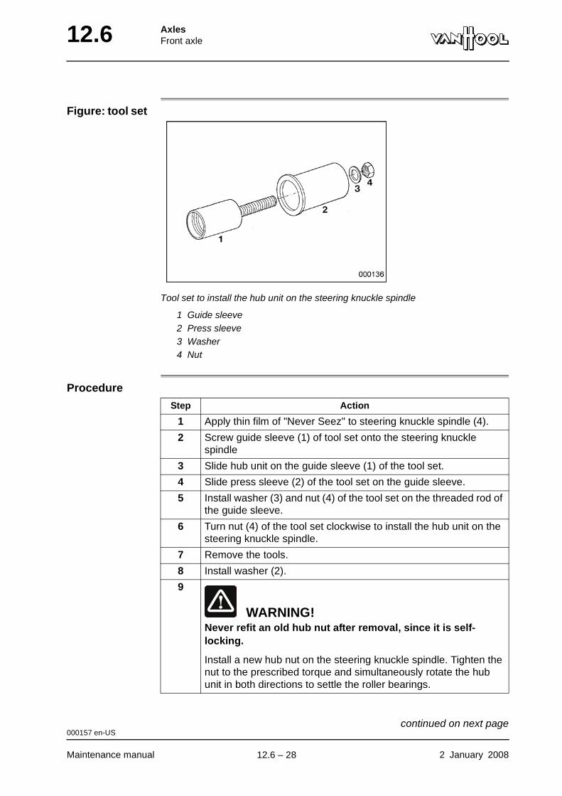
12.6 AxlesFront axle
Figure: tool set
Tool set to install the hub unit on the steering knuckle spindle
1 Guide sleeve2 Press sleeve3 Washer4 Nut
Procedure
Step Action
1 Apply thin film of "Never Seez" to steering knuckle spindle (4).
2 Screw guide sleeve (1) of tool set onto the steering knuckle spindle
3 Slide hub unit on the guide sleeve (1) of the tool set.
4 Slide press sleeve (2) of the tool set on the guide sleeve.
5 Install washer (3) and nut (4) of the tool set on the threaded rod of the guide sleeve.
6 Turn nut (4) of the tool set clockwise to install the hub unit on the steering knuckle spindle.
7 Remove the tools.
8 Install washer (2).
9
WARNING!Never refit an old hub nut after removal, since it is self-locking.
Install a new hub nut on the steering knuckle spindle. Tighten the nut to the prescribed torque and simultaneously rotate the hub unit in both directions to settle the roller bearings.
000157 en-US
Maintenance manual 2 January 2008
continued on next page.
12.6 – 28
AxlesFront axle 12.6
10 Apply a thin film of NLGI No. 2 grade high temperature lithium grease to the contact surfaces between brake disc (6) and hub unit (5).
11 Put brake disc (6) on a flat surface. Position wheel flange (7) on brake disc (6) in such a way that the holes for screw (8) coincide. Secure wheel flange (7) to brake disc (6) with hexagonal socket screw (8).
12 Position the wheel flange/brake disc assembly to the hub unit in such a way that the screw holes coincide. Install twelve securing screws (3) and tighten them crosswise in steps.
13 Install the brake caliper/brake carrier assembly. Refer to "To install brake caliper/brake carrier" in chapter 5.10.
Step Action
000157 en-US
2 January 2008 Maintenance manual
.
12.6 – 29
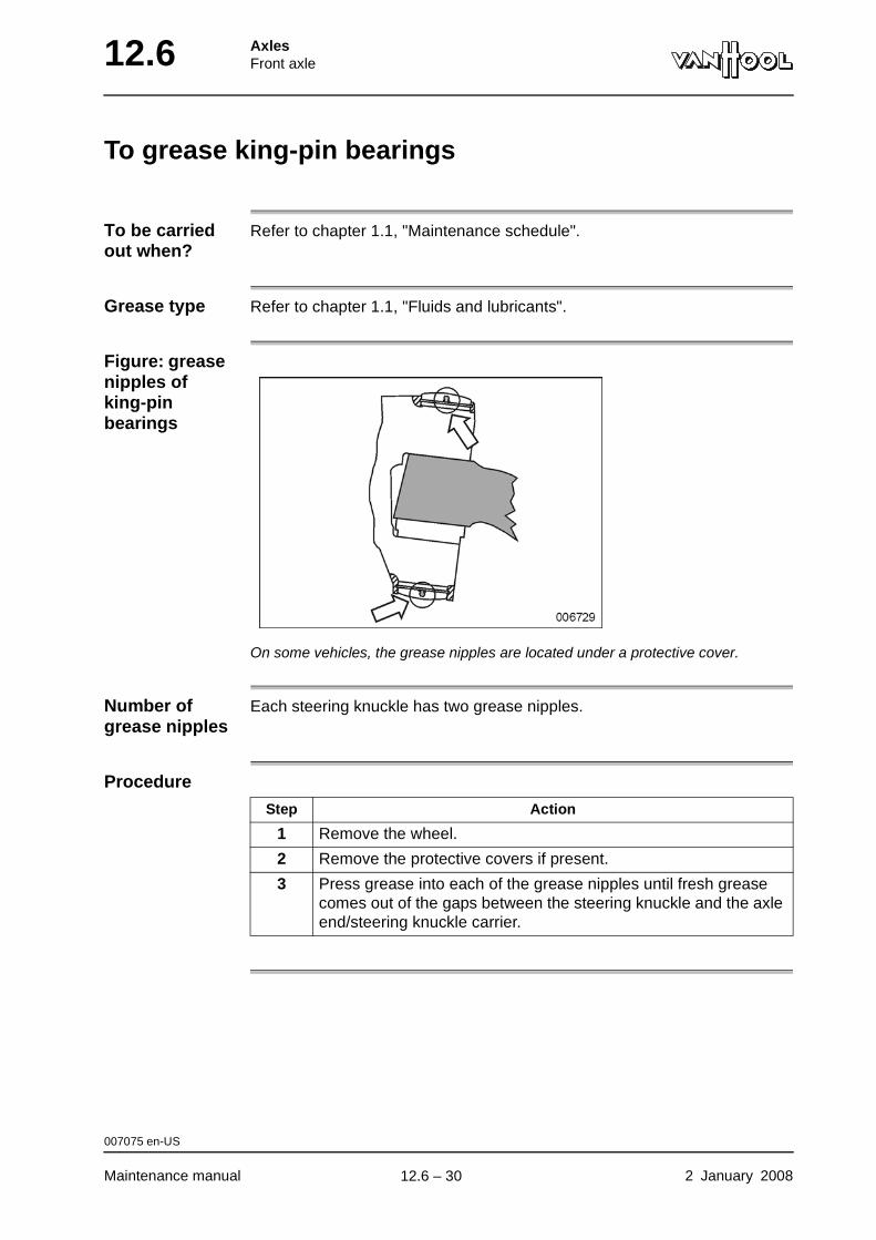
12.6 AxlesFront axle
To grease king-pin bearings
To be carried out when?
Refer to chapter 1.1, "Maintenance schedule".
Grease type Refer to chapter 1.1, "Fluids and lubricants".
Figure: grease nipples of king-pin bearings
On some vehicles, the grease nipples are located under a protective cover.
Number of grease nipples
Each steering knuckle has two grease nipples.
Procedure
Step Action
1 Remove the wheel.
2 Remove the protective covers if present.
3 Press grease into each of the grease nipples until fresh grease comes out of the gaps between the steering knuckle and the axle end/steering knuckle carrier.
007075 en-US
Maintenance manual 2 January 2008
.
12.6 – 30
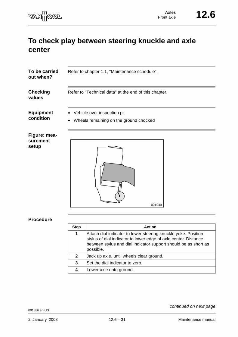
AxlesFront axle 12.6
To check play between steering knuckle and axle center
To be carried out when?
Refer to chapter 1.1, "Maintenance schedule".
Checking values
Refer to "Technical data" at the end of this chapter.
Equipment condition
• Vehicle over inspection pit
• Wheels remaining on the ground chocked
Figure: mea-surement setup
Procedure
Step Action
1 Attach dial indicator to lower steering knuckle yoke. Position stylus of dial indicator to lower edge of axle center. Distance between stylus and dial indicator support should be as short as possible.
2 Jack up axle, until wheels clear ground.
3 Set the dial indicator to zero.
4 Lower axle onto ground.
001386 en-US
2 January 2008 Maintenance manual
continued on next page.
12.6 – 31
12.6 AxlesFront axle
5 Note variation shown by dial indicator.
Is variation smaller than maximum permissible value?
• If so, axial clearance is correct.
• If not, remove steering knuckle and replace all damaged parts.
Step Action
001386 en-US
Maintenance manual 2 January 2008
.
12.6 – 32

AxlesFront axle 12.6
Technical data: front axle
Make Van Hool
Geometry
Wheel hub
Steering knuckle
Tightening torques
Caster 3° ± 15’
Camber +15’ ± 15’
King-pin inclination 7°
Toe-out (degrees) -5’ ± 2’
Toe-out (inch) -0.02 ± 0.006 in/ft
Maximum steering angle, inner wheel
• 22.5” x 8.25” wheel 57°
• 22.5” x 9” wheel 55°
Wheel bearing end-play maximum 0.01 in
Axial clearance
• new maximum 0.008 in
• at routine checks according to maintenance schedule
maximum 0.016 in
Hub nut 545 ± 30 ft.lbf
Hexagonal socket screw for securing wheel flange to brake disc (M12 x 1.5)
55 ± 7 ft.lbf
Screws for securing wheel flange/brake disc to hub unit (M18 x 1.5 -10.9)
320 ± 20 ft.lbf
Air spring piston to steering knuckle carrier 52 ± 7 ft.lbf
Shock absorber nut 70 ft.lbf
Nut of tie-rod clamping bolt 60 ± 7 ft.lbf
003406 en-US
2 January 2008 Maintenance manual
continued on next page.
12.6 – 33
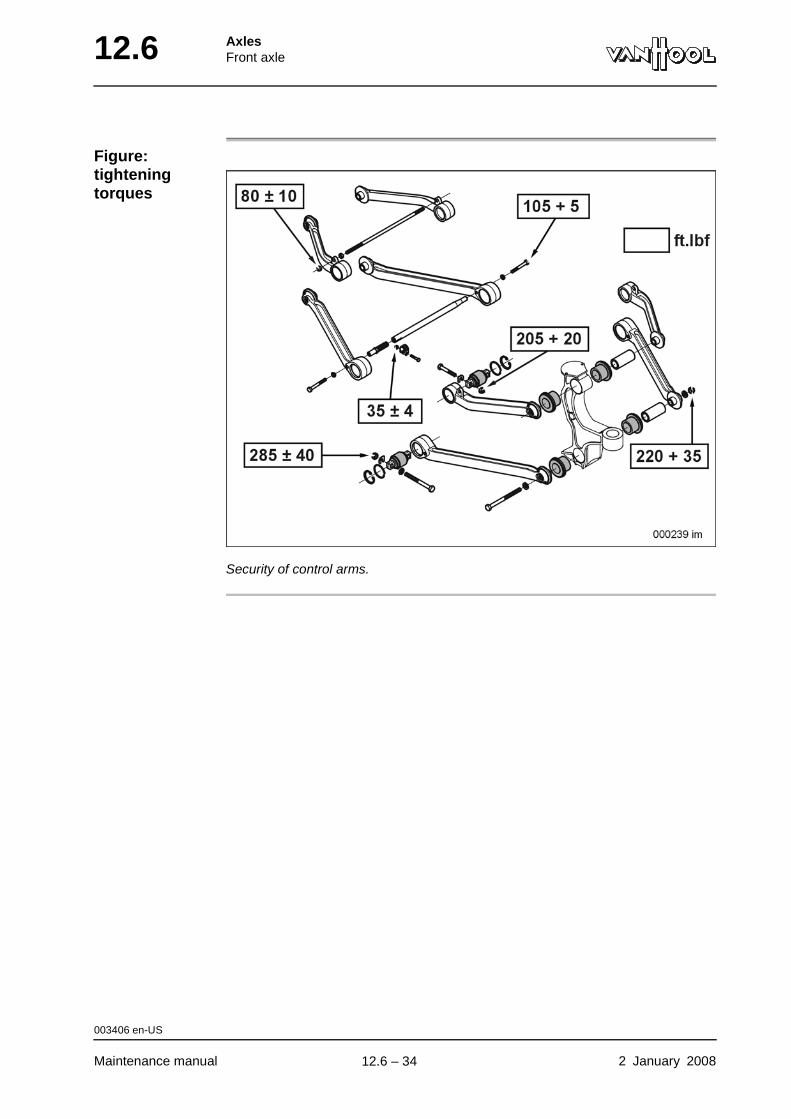
12.6 AxlesFront axle
Figure: tightening torques
Security of control arms.
003406 en-US
Maintenance manual 2 January 2008
.
12.6 – 34
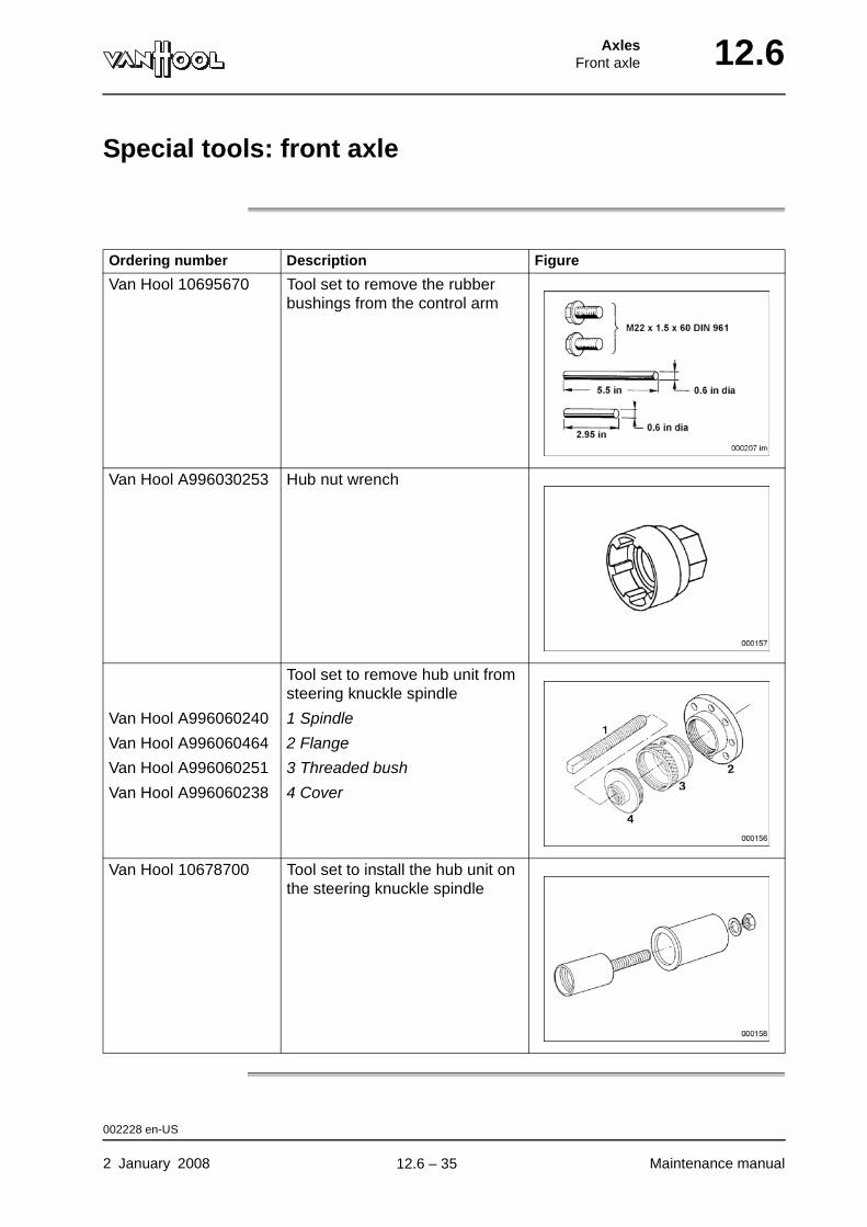
AxlesFront axle 12.6
Special tools: front axle
Ordering number Description Figure
Van Hool 10695670 Tool set to remove the rubber bushings from the control arm
Van Hool A996030253 Hub nut wrench
Tool set to remove hub unit from steering knuckle spindle
Van Hool A996060240 1 Spindle
Van Hool A996060464 2 Flange
Van Hool A996060251 3 Threaded bush
Van Hool A996060238 4 Cover
Van Hool 10678700 Tool set to install the hub unit on the steering knuckle spindle
002228 en-US
2 January 2008 Maintenance manual
.
12.6 – 35
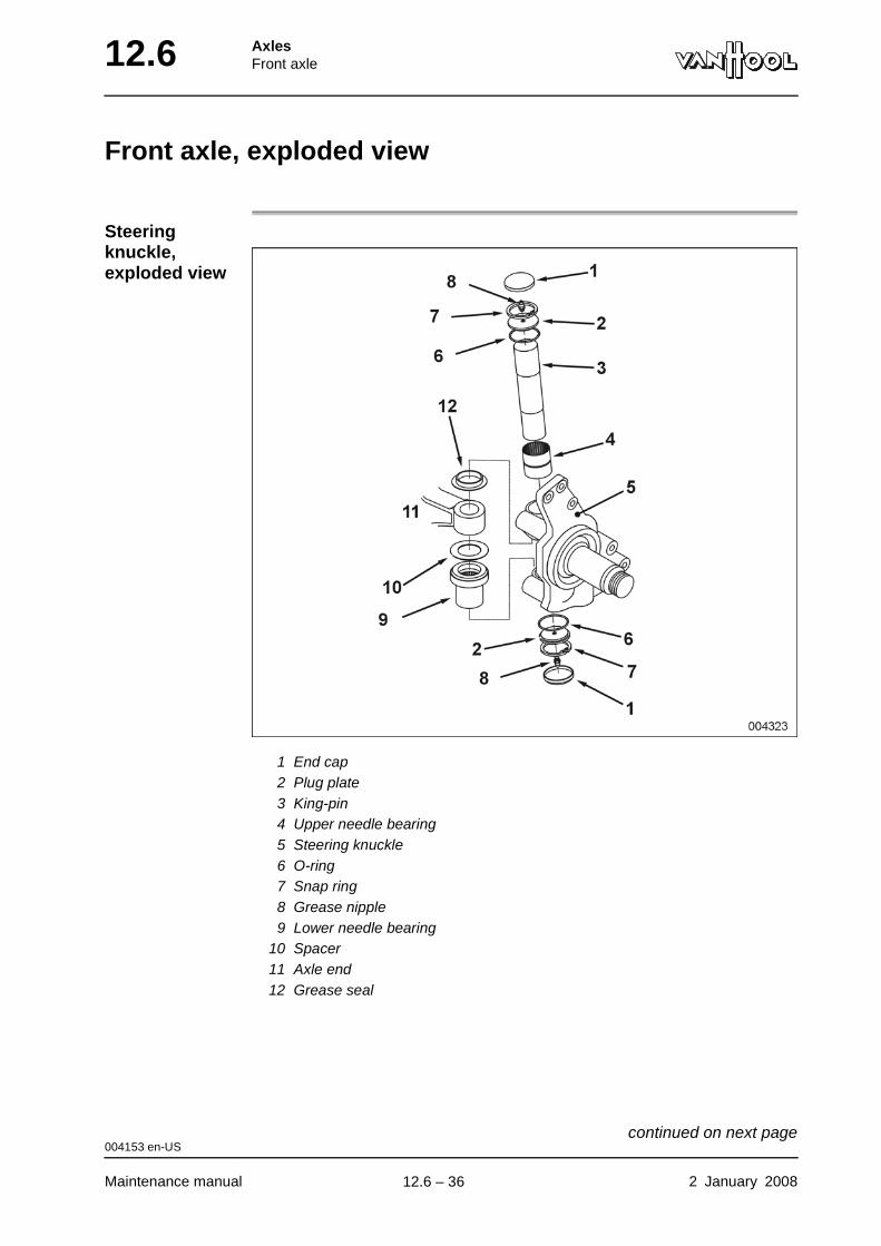
12.6 AxlesFront axle
Front axle, exploded view
Steering knuckle, exploded view
1 End cap2 Plug plate3 King-pin4 Upper needle bearing5 Steering knuckle6 O-ring7 Snap ring8 Grease nipple9 Lower needle bearing
10 Spacer11 Axle end12 Grease seal
004153 en-US
Maintenance manual 2 January 2008
continued on next page.
12.6 – 36
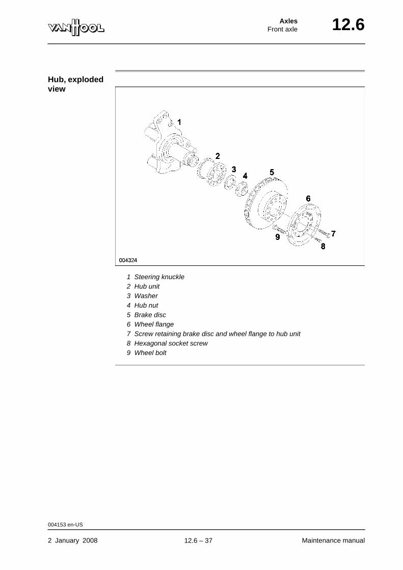
AxlesFront axle 12.6
Hub, exploded view
1 Steering knuckle2 Hub unit3 Washer4 Hub nut5 Brake disc6 Wheel flange7 Screw retaining brake disc and wheel flange to hub unit8 Hexagonal socket screw9 Wheel bolt
004153 en-US
2 January 2008 Maintenance manual
.
12.6 – 37
12.6 AxlesFront axle
This page has been intentionally left blank.
004153 en-US
Maintenance manual 2 January 200812.6 – 38

AxlesDrive axle 12.10
Chapter 10: Drive axle
Overview
Introduction This chapter deals with the drive axle.
Number of pages
12
Chapter publi-cation date
2 January 2008
Contents
Topic See page
To check oil level 12.10-2
To change oil 12.10-4
To remove wheel bearing 12.10-5
To install wheel bearing 12.10-7
To check breather 12.10-10
Technical data: drive axle 12.10-11
Special tools: drive axle 12.10-12
2 January 2008 Maintenance manual
.
12.10 – 1
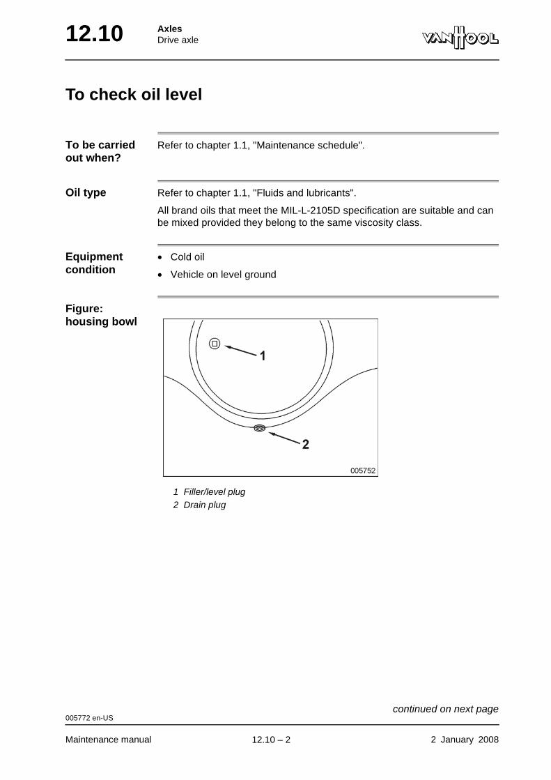
12.10 AxlesDrive axle
To check oil level
To be carried out when?
Refer to chapter 1.1, "Maintenance schedule".
Oil type Refer to chapter 1.1, "Fluids and lubricants".
All brand oils that meet the MIL-L-2105D specification are suitable and can be mixed provided they belong to the same viscosity class.
Equipment condition
• Cold oil
• Vehicle on level ground
Figure: housing bowl
1 Filler/level plug2 Drain plug
005772 en-US
Maintenance manual 2 January 2008
continued on next page.
12.10 – 2
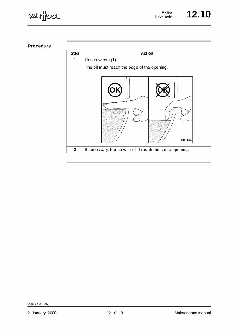
AxlesDrive axle 12.10
Procedure
Step Action
1 Unscrew cap (1).
The oil must reach the edge of the opening.
2 If necessary, top up with oil through the same opening.
005772 en-US
2 January 2008 Maintenance manual
.
12.10 – 3
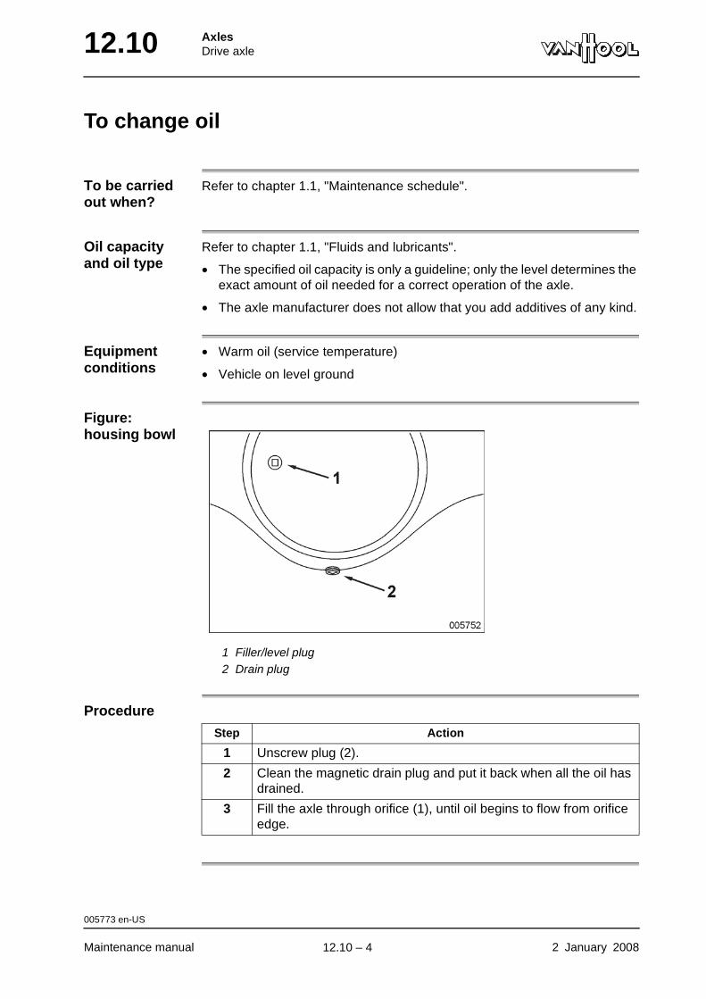
12.10 AxlesDrive axle
To change oil
To be carried out when?
Refer to chapter 1.1, "Maintenance schedule".
Oil capacity and oil type
Refer to chapter 1.1, "Fluids and lubricants".
• The specified oil capacity is only a guideline; only the level determines the exact amount of oil needed for a correct operation of the axle.
• The axle manufacturer does not allow that you add additives of any kind.
Equipment conditions
• Warm oil (service temperature)
• Vehicle on level ground
Figure: housing bowl
1 Filler/level plug2 Drain plug
Procedure
Step Action
1 Unscrew plug (2).
2 Clean the magnetic drain plug and put it back when all the oil has drained.
3 Fill the axle through orifice (1), until oil begins to flow from orifice edge.
005773 en-US
Maintenance manual 2 January 2008
.
12.10 – 4

AxlesDrive axle 12.10
To remove wheel bearing
Special tool
Equipment condition
• Wheels remaining on the ground chocked
• Drive axle jacked up
• Road wheel removed
Figure: section through axle end
1 Axle shaft2 Wheel hub3 Sealing ring (part of wheel bearing)4 Brake disc5 Wheel bearing6 Washer7 Hub nut8 Axle spindle
Hub nut wrench Van Hool No. 10732280
005039 en-US
2 January 2008 Maintenance manual
continued on next page.
12.10 – 5
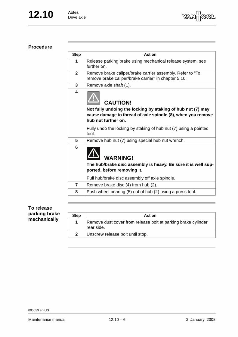
12.10 AxlesDrive axle
Procedure
To release parking brake mechanically
Step Action
1 Release parking brake using mechanical release system, see further on.
2 Remove brake caliper/brake carrier assembly. Refer to "To remove brake caliper/brake carrier" in chapter 5.10.
3 Remove axle shaft (1).
4
CAUTION!Not fully undoing the locking by staking of hub nut (7) may cause damage to thread of axle spindle (8), when you remove hub nut further on.
Fully undo the locking by staking of hub nut (7) using a pointed tool.
5 Remove hub nut (7) using special hub nut wrench.
6
WARNING!The hub/brake disc assembly is heavy. Be sure it is well sup-ported, before removing it.
Pull hub/brake disc assembly off axle spindle.
7 Remove brake disc (4) from hub (2).
8 Push wheel bearing (5) out of hub (2) using a press tool.
Step Action
1 Remove dust cover from release bolt at parking brake cylinder rear side.
2 Unscrew release bolt until stop.
005039 en-US
Maintenance manual 2 January 2008
.
12.10 – 6
AxlesDrive axle 12.10
To install wheel bearing
Consumables
Special tool
Tightening torques
Refer to "Technical data" at the end of this chapter.
Wheel bearing Van Hool No. 10875658
Hub nut + washer Van Hool No. 10963147
Hub nut wrench Van Hool No. 10732280
Drift to press wheel bearing in hub Van Hool No. 10914289
Guide sleeve to slide hub on axle spindle
Van Hool No. 10920992
005041 en-US
2 January 2008 Maintenance manual
continued on next page.
12.10 – 7

12.10 AxlesDrive axle
Figure: section through axle end
1 Axle shaft2 Wheel hub3 Sealing ring (part of wheel bearing)4 Brake disc5 Wheel bearing6 Washer7 Hub nut8 Axle spindle
Procedure
Step Action
1 Position wheel bearing (5) on hole in hub (2) so that sealing ring (3) is located at the bottom.
2 Press wheel bearing (5) into hub (2) using special drift.
3 Position brake disc (4) onto hub (2). Install fixing screws and tighten them to the prescribed torque.
4 Clean axle spindle (8).
5 Check thread of axle spindle (8) for damage. If necessary, repair thread.
6 Apply a thin film of "Never Seez" onto axle spindle (8).
7 Screw special guide sleeve onto axle spindle (8).
005041 en-US
Maintenance manual 2 January 2008
continued on next page.
12.10 – 8
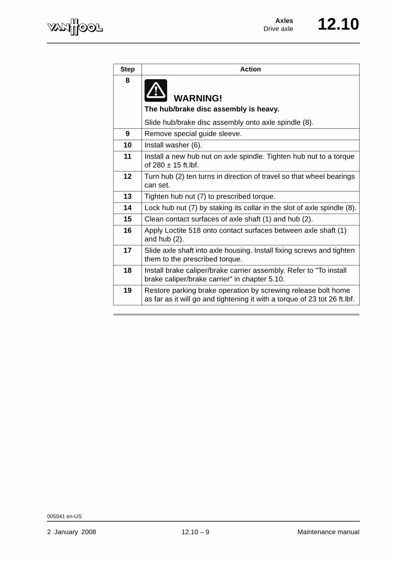
AxlesDrive axle 12.10
8
WARNING!The hub/brake disc assembly is heavy.
Slide hub/brake disc assembly onto axle spindle (8).
9 Remove special guide sleeve.
10 Install washer (6).
11 Install a new hub nut on axle spindle. Tighten hub nut to a torque of 280 ± 15 ft.lbf.
12 Turn hub (2) ten turns in direction of travel so that wheel bearings can set.
13 Tighten hub nut (7) to prescribed torque.
14 Lock hub nut (7) by staking its collar in the slot of axle spindle (8).
15 Clean contact surfaces of axle shaft (1) and hub (2).
16 Apply Loctite 518 onto contact surfaces between axle shaft (1) and hub (2).
17 Slide axle shaft into axle housing. Install fixing screws and tighten them to the prescribed torque.
18 Install brake caliper/brake carrier assembly. Refer to "To install brake caliper/brake carrier" in chapter 5.10.
19 Restore parking brake operation by screwing release bolt home as far as it will go and tightening it with a torque of 23 tot 26 ft.lbf.
Step Action
005041 en-US
2 January 2008 Maintenance manual
.
12.10 – 9
12.10 AxlesDrive axle
To check breather
To be carried out when?
Refer to chapter 1.1, "Maintenance schedule".
Procedure Check whether breather passage is open (clean if necessary).
000551 en-US
Maintenance manual 2 January 2008
.
12.10 – 10
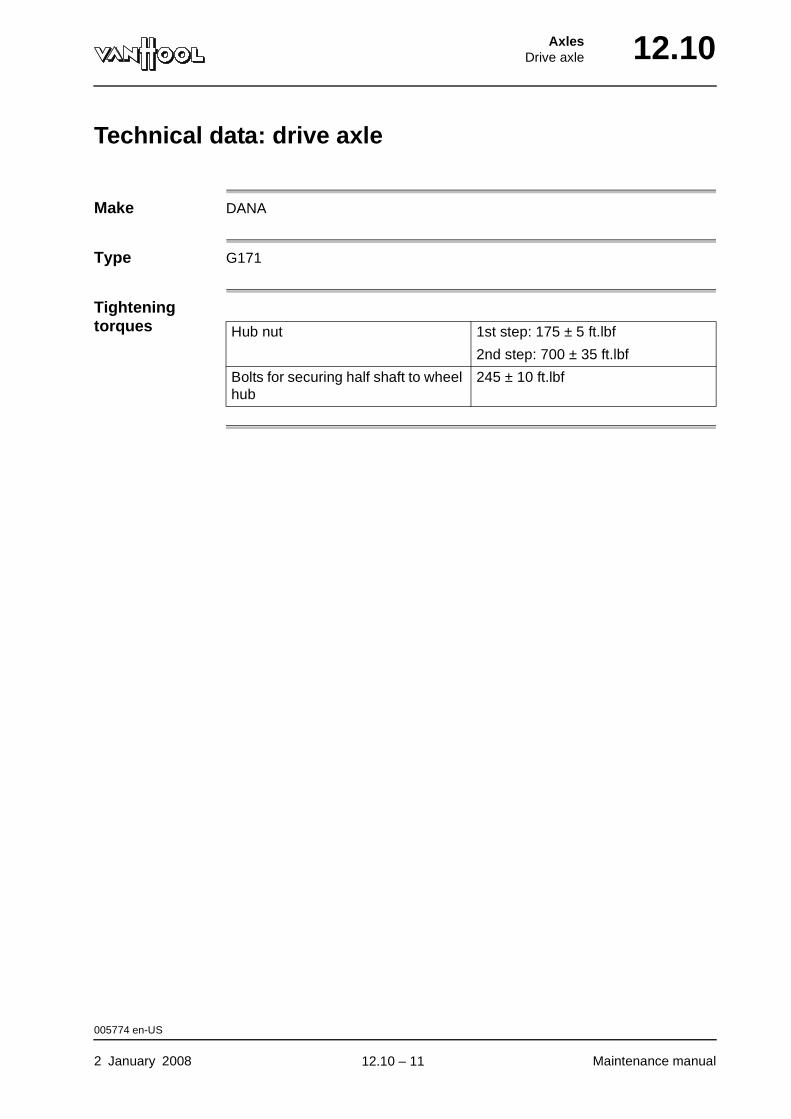
AxlesDrive axle 12.10
Technical data: drive axle
Make DANA
Type G171
Tightening torques Hub nut 1st step: 175 ± 5 ft.lbf
2nd step: 700 ± 35 ft.lbf
Bolts for securing half shaft to wheel hub
245 ± 10 ft.lbf
005774 en-US
2 January 2008 Maintenance manual
.
12.10 – 11

12.10 AxlesDrive axle
Special tools: drive axle
Ordering number Description Figure
Van Hool 10732280 Hub nut wrench
Van Hool 10914289 Drift to press wheel bearing in hub.
Van Hool 10920992 Guide sleeve to slide hub on axle spindle.
004158 en-US
Maintenance manual 2 January 2008
.
12.10 – 12
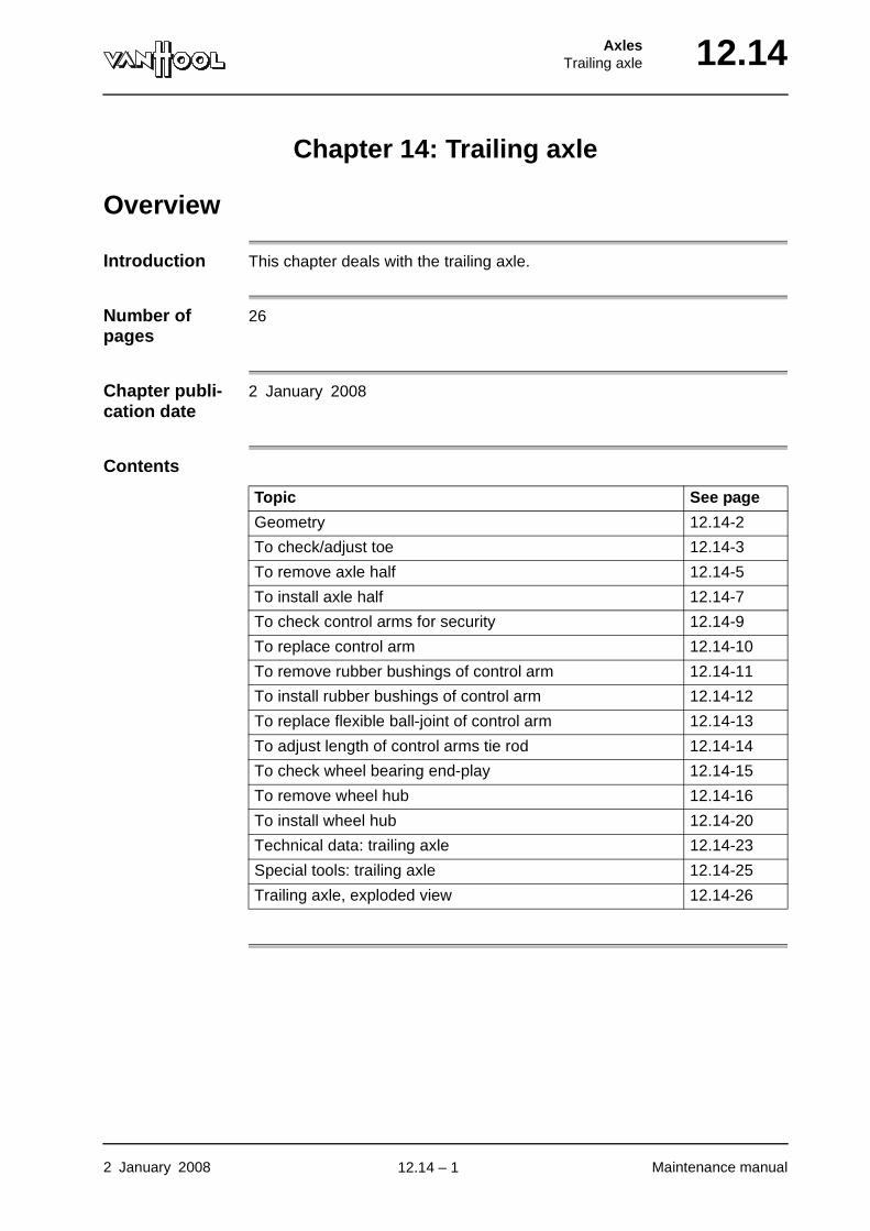
AxlesTrailing axle 12.14
Chapter 14: Trailing axle
Overview
Introduction This chapter deals with the trailing axle.
Number of pages
26
Chapter publi-cation date
2 January 2008
Contents
Topic See page
Geometry 12.14-2
To check/adjust toe 12.14-3
To remove axle half 12.14-5
To install axle half 12.14-7
To check control arms for security 12.14-9
To replace control arm 12.14-10
To remove rubber bushings of control arm 12.14-11
To install rubber bushings of control arm 12.14-12
To replace flexible ball-joint of control arm 12.14-13
To adjust length of control arms tie rod 12.14-14
To check wheel bearing end-play 12.14-15
To remove wheel hub 12.14-16
To install wheel hub 12.14-20
Technical data: trailing axle 12.14-23
Special tools: trailing axle 12.14-25
Trailing axle, exploded view 12.14-26
2 January 2008 Maintenance manual
.
12.14 – 1
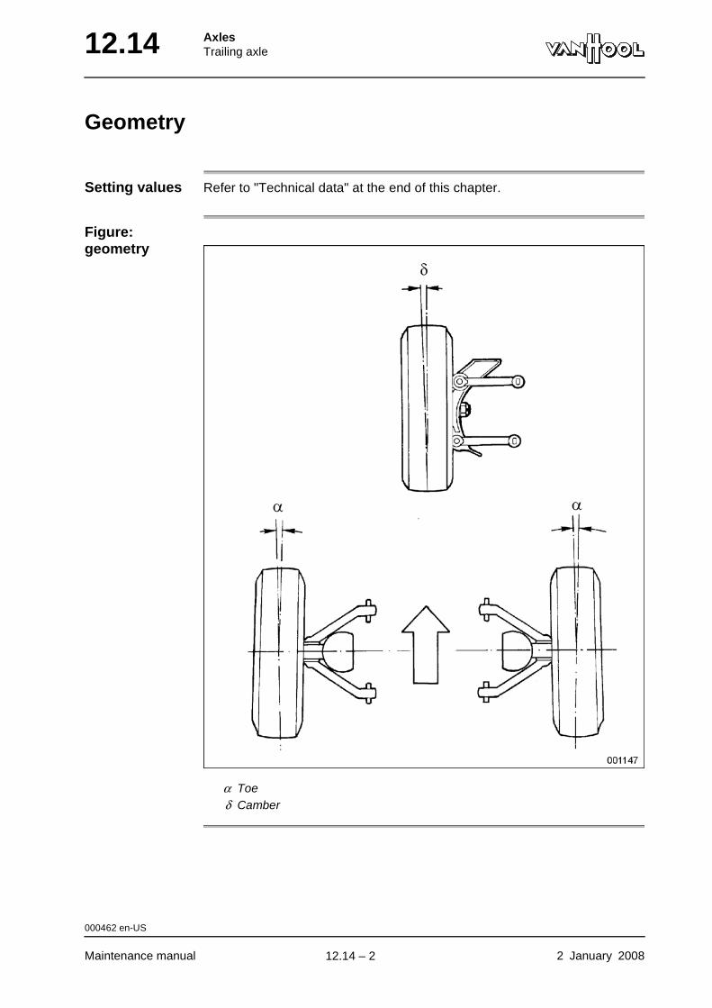
12.14 AxlesTrailing axle
Geometry
Setting values Refer to "Technical data" at the end of this chapter.
Figure: geometry
α Toeδ Camber
000462 en-US
Maintenance manual 2 January 2008
.
12.14 – 2
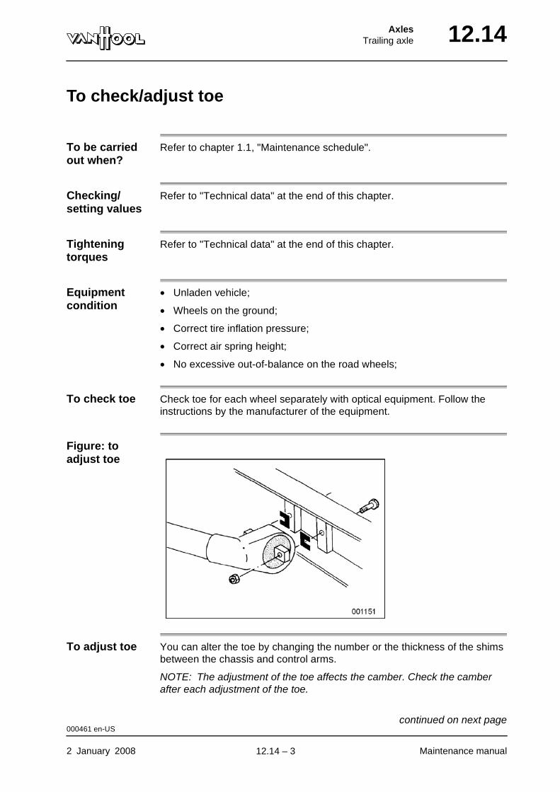
AxlesTrailing axle 12.14
To check/adjust toe
To be carried out when?
Refer to chapter 1.1, "Maintenance schedule".
Checking/setting values
Refer to "Technical data" at the end of this chapter.
Tightening torques
Refer to "Technical data" at the end of this chapter.
Equipment condition
• Unladen vehicle;
• Wheels on the ground;
• Correct tire inflation pressure;
• Correct air spring height;
• No excessive out-of-balance on the road wheels;
To check toe Check toe for each wheel separately with optical equipment. Follow the instructions by the manufacturer of the equipment.
Figure: to adjust toe
To adjust toe You can alter the toe by changing the number or the thickness of the shims between the chassis and control arms.
NOTE: The adjustment of the toe affects the camber. Check the camber after each adjustment of the toe.
000461 en-US
2 January 2008 Maintenance manual
continued on next page.
12.14 – 3
12.14 AxlesTrailing axle
000461 en-US
Maintenance manual 2 January 2008
.
12.14 – 4
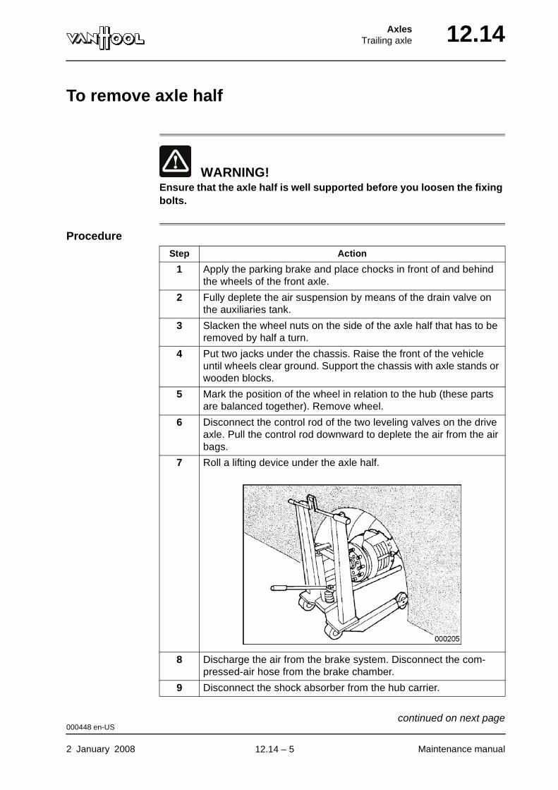
AxlesTrailing axle 12.14
To remove axle half
WARNING!Ensure that the axle half is well supported before you loosen the fixing bolts.
Procedure
Step Action
1 Apply the parking brake and place chocks in front of and behind the wheels of the front axle.
2 Fully deplete the air suspension by means of the drain valve on the auxiliaries tank.
3 Slacken the wheel nuts on the side of the axle half that has to be removed by half a turn.
4 Put two jacks under the chassis. Raise the front of the vehicle until wheels clear ground. Support the chassis with axle stands or wooden blocks.
5 Mark the position of the wheel in relation to the hub (these parts are balanced together). Remove wheel.
6 Disconnect the control rod of the two leveling valves on the drive axle. Pull the control rod downward to deplete the air from the air bags.
7 Roll a lifting device under the axle half.
8 Discharge the air from the brake system. Disconnect the com-pressed-air hose from the brake chamber.
9 Disconnect the shock absorber from the hub carrier.
000448 en-US
2 January 2008 Maintenance manual
continued on next page.
12.14 – 5

12.14 AxlesTrailing axle
10 Remove the bolts securing the air bag piston to the hub carrier.
11 NOTE: Make note of the number and the position of the camber adjustment shims for re-use during assembly.
Unscrew the nuts of the four bolts securing the upper control arms to the chassis, then remove the four nuts of the lower control arms.
12 Withdraw the axle half from the vehicle.
Step Action
000448 en-US
Maintenance manual 2 January 2008
.
12.14 – 6
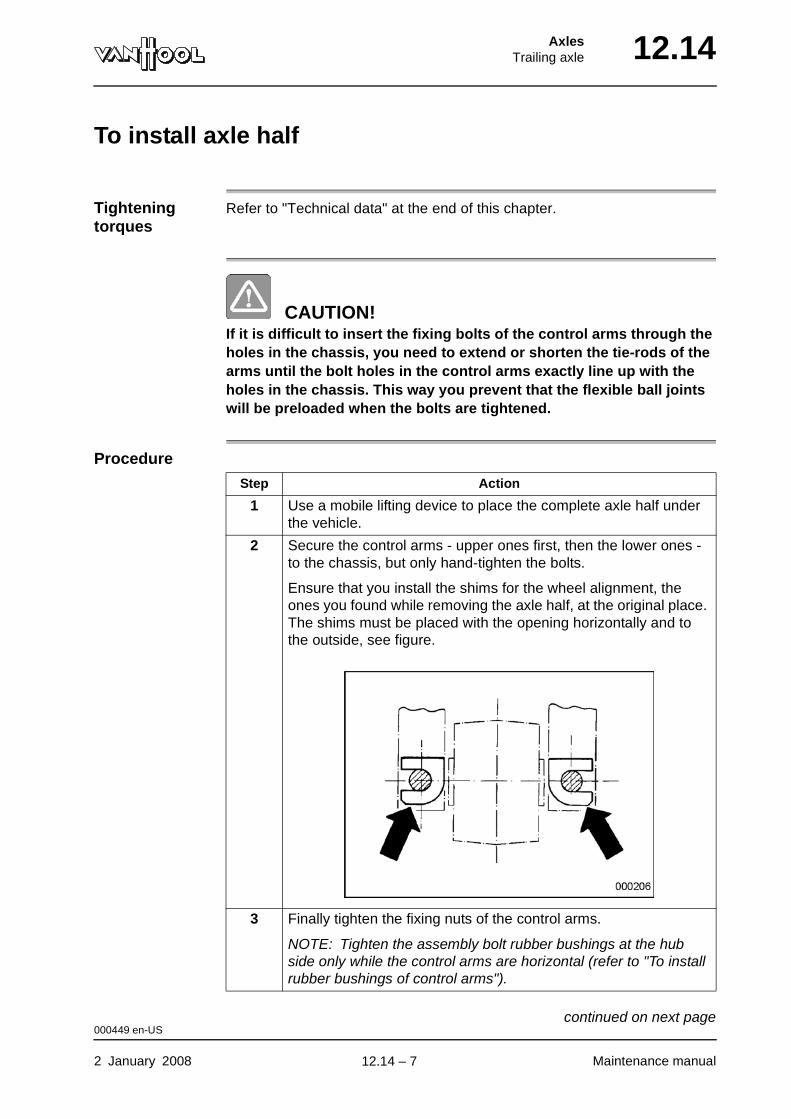
AxlesTrailing axle 12.14
To install axle half
Tightening torques
Refer to "Technical data" at the end of this chapter.
CAUTION!If it is difficult to insert the fixing bolts of the control arms through the holes in the chassis, you need to extend or shorten the tie-rods of the arms until the bolt holes in the control arms exactly line up with the holes in the chassis. This way you prevent that the flexible ball joints will be preloaded when the bolts are tightened.
Procedure
Step Action
1 Use a mobile lifting device to place the complete axle half under the vehicle.
2 Secure the control arms - upper ones first, then the lower ones - to the chassis, but only hand-tighten the bolts.
Ensure that you install the shims for the wheel alignment, the ones you found while removing the axle half, at the original place. The shims must be placed with the opening horizontally and to the outside, see figure.
3 Finally tighten the fixing nuts of the control arms.
NOTE: Tighten the assembly bolt rubber bushings at the hub side only while the control arms are horizontal (refer to "To install rubber bushings of control arms").
000449 en-US
2 January 2008 Maintenance manual
continued on next page.
12.14 – 7
12.14 AxlesTrailing axle
4 Secure air spring piston to the hub carrier. Tighten the screws to the prescribed torque.
5 Secure shock absorber to the hub carrier. Tighten self-locking nut to prescribed torque.
6 Secure compressed-air hose to the brake chamber.
7 Reconnect the control rod of the two leveling valves to its con-nection support.
8 Place the wheel and lower the vehicle.
9 Pressurize the air system and adjust the height of the air springs as described in "To adjust air spring height" in chapter 3.6.
10 Adjust toe, refer to "To check/adjust toe".
11 Road-test vehicle and recheck the toe.
Step Action
000449 en-US
Maintenance manual 2 January 2008
.
12.14 – 8
AxlesTrailing axle 12.14
To check control arms for security
Tightening torques
Refer to "Technical data" at the end of this chapter.
Procedure Visually check those bolts, screws and nuts that are locked by means of a cotter pin, a locking plate or locking adhesive (Loctite). The security of all others must be checked mechanically. Retighten, if necessary.
WARNING!Do not retighten bolts, screws or nuts that have been locked by means of locking adhesive (Loctite), as this would destroy the locking prop-erties.
004065 en-US
2 January 2008 Maintenance manual
.
12.14 – 9

12.14 AxlesTrailing axle
To replace control arm
CAUTION!Control arms are not interchangeable.
Location of the control arms A(n)... is located correctly if...
upper control arm the cast rib with the hole for the tie rod is on top.
lower control arm the cast rib with the hole for the tie rod is at the bottom.
000450 en-US
Maintenance manual 2 January 2008
.
12.14 – 10
AxlesTrailing axle 12.14
To remove rubber bushings of control arm
Cross-reference
Refer to chapter 12.6, "To remove rubber bushings of control arm".
000451 en-US
2 January 2008 Maintenance manual
.
12.14 – 11

12.14 AxlesTrailing axle
To install rubber bushings of control arm
Cross-reference
Refer to chapter 12.6, "To install rubber bushings of control arm".
000452 en-US
Maintenance manual 2 January 2008
.
12.14 – 12
AxlesTrailing axle 12.14
To replace flexible ball-joint of control arm
Cross-reference
Refer to chapter 12.6, "To replace flexible ball-joint of control arm".
000453 en-US
2 January 2008 Maintenance manual
.
12.14 – 13
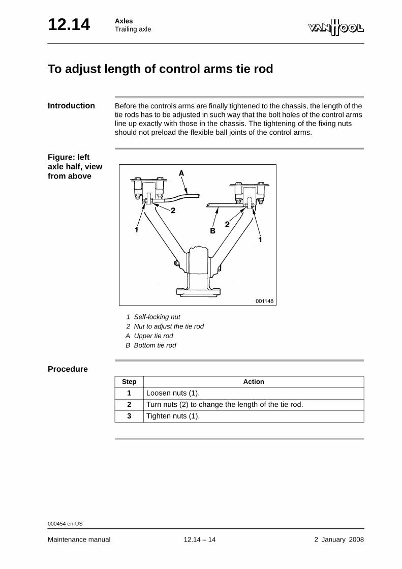
12.14 AxlesTrailing axle
To adjust length of control arms tie rod
Introduction Before the controls arms are finally tightened to the chassis, the length of the tie rods has to be adjusted in such way that the bolt holes of the control arms line up exactly with those in the chassis. The tightening of the fixing nuts should not preload the flexible ball joints of the control arms.
Figure: left axle half, view from above
1 Self-locking nut2 Nut to adjust the tie rodA Upper tie rodB Bottom tie rod
Procedure
Step Action
1 Loosen nuts (1).
2 Turn nuts (2) to change the length of the tie rod.
3 Tighten nuts (1).
000454 en-US
Maintenance manual 2 January 2008
.
12.14 – 14
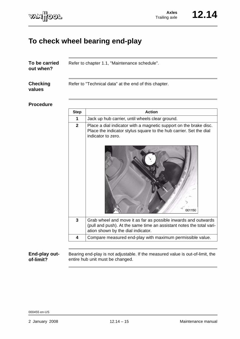
AxlesTrailing axle 12.14
To check wheel bearing end-play
To be carried out when?
Refer to chapter 1.1, "Maintenance schedule".
Checking values
Refer to "Technical data" at the end of this chapter.
Procedure
End-play out-of-limit?
Bearing end-play is not adjustable. If the measured value is out-of-limit, the entire hub unit must be changed.
Step Action
1 Jack up hub carrier, until wheels clear ground.
2 Place a dial indicator with a magnetic support on the brake disc. Place the indicator stylus square to the hub carrier. Set the dial indicator to zero.
3 Grab wheel and move it as far as possible inwards and outwards (pull and push). At the same time an assistant notes the total vari-ation shown by the dial indicator.
4 Compare measured end-play with maximum permissible value.
000455 en-US
2 January 2008 Maintenance manual
.
12.14 – 15
12.14 AxlesTrailing axle
To remove wheel hub
Special tools
Equipment condition
• Wheels remaining on the ground chocked
• Trailing axle jacked up
• Road wheel removed
• Brake caliper/brake carrier removed, refer to "To remove brake caliper/brake carrier" in chapter 5.10.
Hub nut wrench Van Hool No. A996030253
Tool set to remove hub unit from axle spindle
• Spindle
• Flange
• Threaded bush
• Cover
• Van Hool No. A996060240
• Van Hool No. A996060464
• Van Hool No. A996060251
• Van Hool No. A996060238
000456 en-US
Maintenance manual 2 January 2008
continued on next page.
12.14 – 16
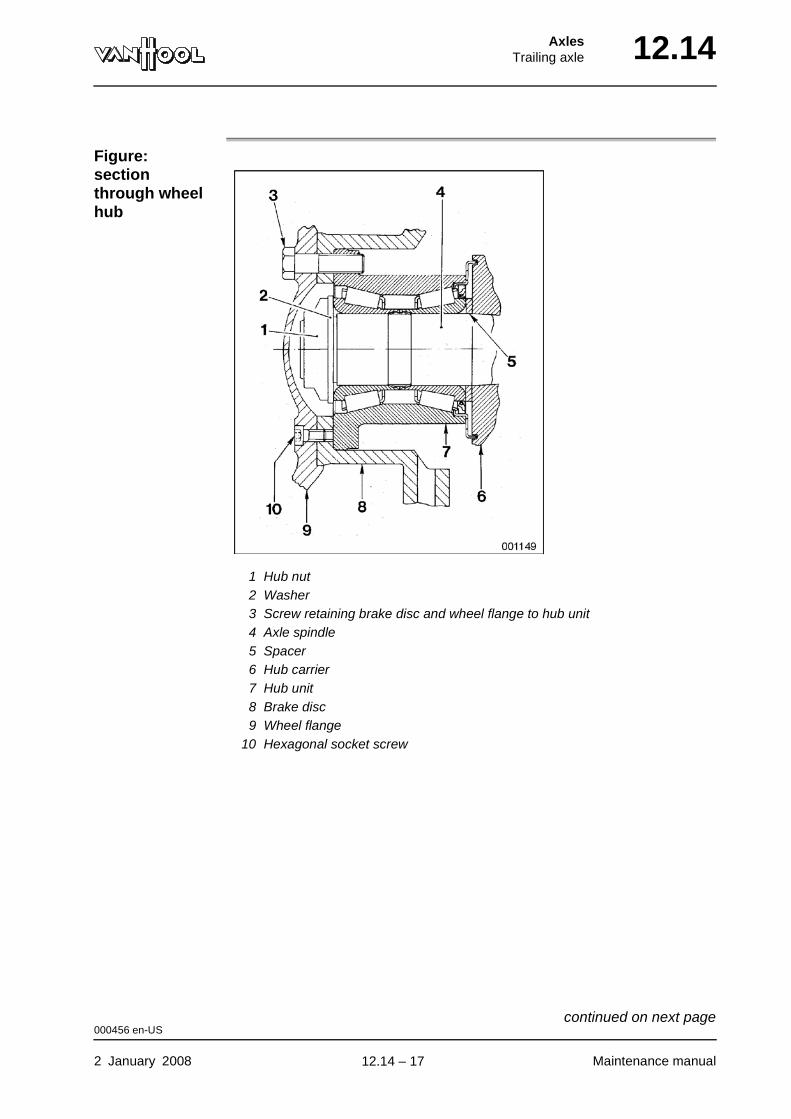
AxlesTrailing axle 12.14
Figure: section through wheel hub
1 Hub nut2 Washer3 Screw retaining brake disc and wheel flange to hub unit4 Axle spindle5 Spacer6 Hub carrier7 Hub unit8 Brake disc9 Wheel flange
10 Hexagonal socket screw
000456 en-US
2 January 2008 Maintenance manual
continued on next page.
12.14 – 17
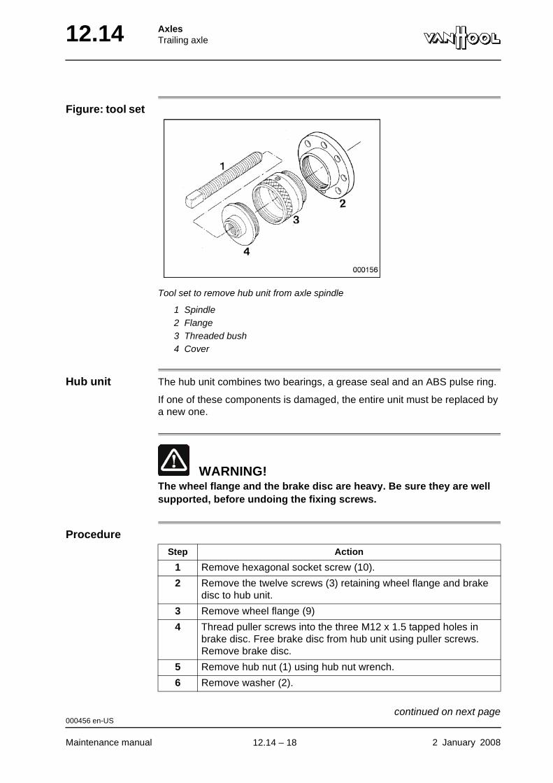
12.14 AxlesTrailing axle
Figure: tool set
Tool set to remove hub unit from axle spindle
1 Spindle2 Flange3 Threaded bush4 Cover
Hub unit The hub unit combines two bearings, a grease seal and an ABS pulse ring.
If one of these components is damaged, the entire unit must be replaced by a new one.
WARNING!The wheel flange and the brake disc are heavy. Be sure they are well supported, before undoing the fixing screws.
Procedure
Step Action
1 Remove hexagonal socket screw (10).
2 Remove the twelve screws (3) retaining wheel flange and brake disc to hub unit.
3 Remove wheel flange (9)
4 Thread puller screws into the three M12 x 1.5 tapped holes in brake disc. Free brake disc from hub unit using puller screws. Remove brake disc.
5 Remove hub nut (1) using hub nut wrench.
6 Remove washer (2).
000456 en-US
Maintenance manual 2 January 2008
continued on next page.
12.14 – 18
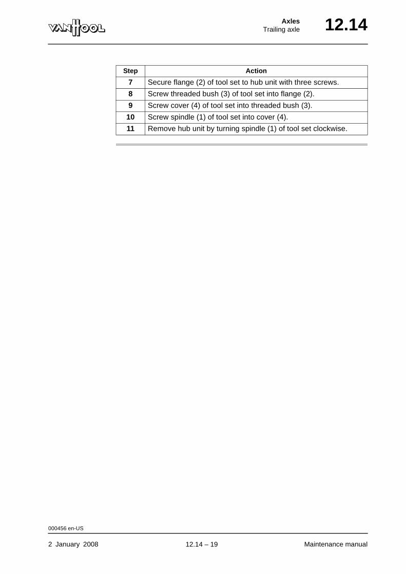
AxlesTrailing axle 12.14
7 Secure flange (2) of tool set to hub unit with three screws.
8 Screw threaded bush (3) of tool set into flange (2).
9 Screw cover (4) of tool set into threaded bush (3).
10 Screw spindle (1) of tool set into cover (4).
11 Remove hub unit by turning spindle (1) of tool set clockwise.
Step Action
000456 en-US
2 January 2008 Maintenance manual
.
12.14 – 19

12.14 AxlesTrailing axle
To install wheel hub
Special tools
Tightening torques
Refer to "Technical data" at the end of this chapter.
Figure: section through wheel hub
1 Hub nut2 Washer3 Screw retaining brake disc and wheel flange to hub unit4 Axle spindle5 Spacer6 Hub carrier7 Hub unit8 Brake disc9 Wheel flange
10 Hexagonal socket screw
Tool set to install the hub unit on the axle spindle
Van Hool No. 10678700
000460 en-US
Maintenance manual 2 January 2008
continued on next page.
12.14 – 20
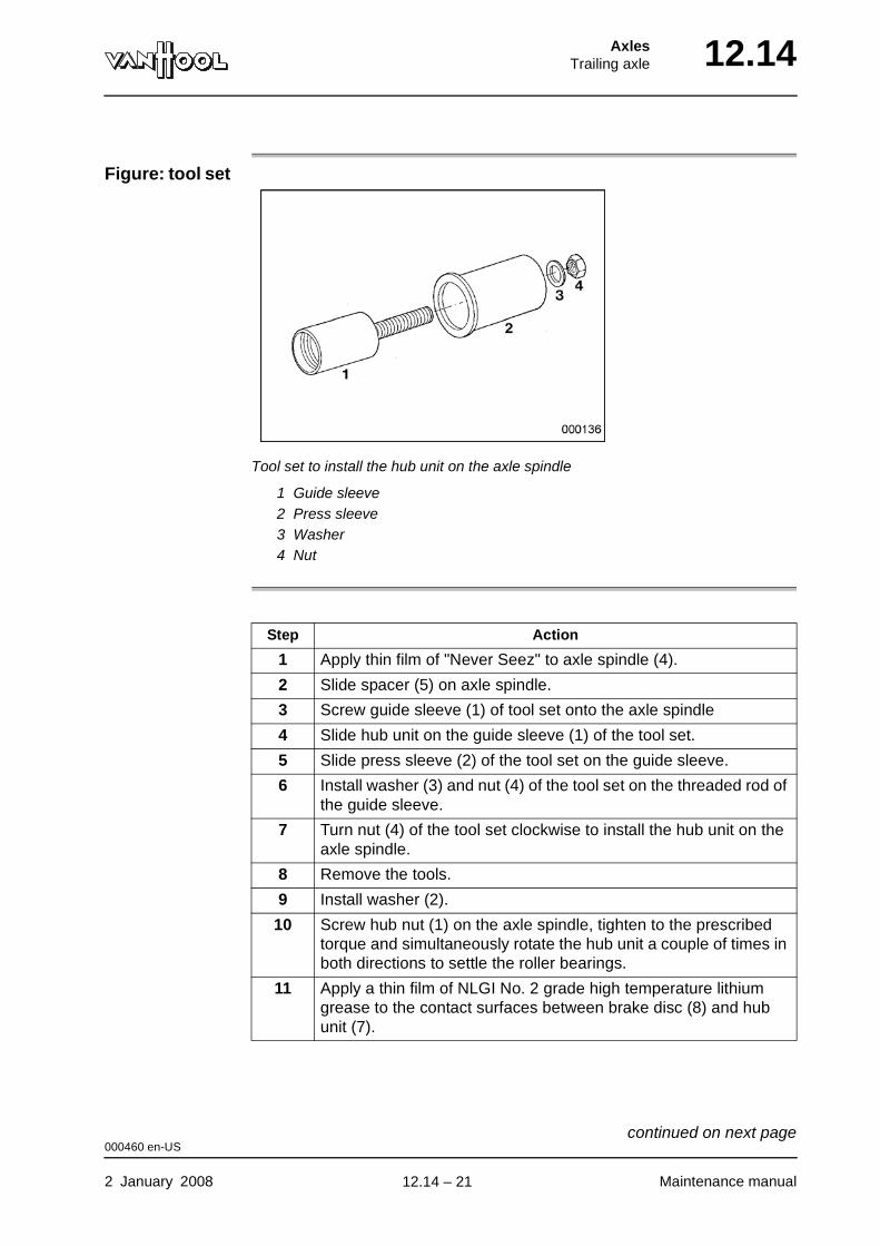
AxlesTrailing axle 12.14
Figure: tool set
Tool set to install the hub unit on the axle spindle
1 Guide sleeve2 Press sleeve3 Washer4 Nut
Step Action
1 Apply thin film of "Never Seez" to axle spindle (4).
2 Slide spacer (5) on axle spindle.
3 Screw guide sleeve (1) of tool set onto the axle spindle
4 Slide hub unit on the guide sleeve (1) of the tool set.
5 Slide press sleeve (2) of the tool set on the guide sleeve.
6 Install washer (3) and nut (4) of the tool set on the threaded rod of the guide sleeve.
7 Turn nut (4) of the tool set clockwise to install the hub unit on the axle spindle.
8 Remove the tools.
9 Install washer (2).
10 Screw hub nut (1) on the axle spindle, tighten to the prescribed torque and simultaneously rotate the hub unit a couple of times in both directions to settle the roller bearings.
11 Apply a thin film of NLGI No. 2 grade high temperature lithium grease to the contact surfaces between brake disc (8) and hub unit (7).
000460 en-US
2 January 2008 Maintenance manual
continued on next page.
12.14 – 21
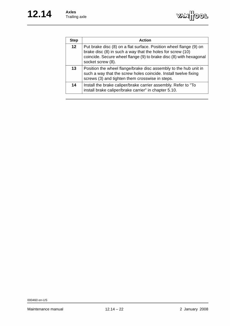
12.14 AxlesTrailing axle
12 Put brake disc (8) on a flat surface. Position wheel flange (9) on brake disc (8) in such a way that the holes for screw (10) coincide. Secure wheel flange (9) to brake disc (8) with hexagonal socket screw (8).
13 Position the wheel flange/brake disc assembly to the hub unit in such a way that the screw holes coincide. Install twelve fixing screws (3) and tighten them crosswise in steps.
14 Install the brake caliper/brake carrier assembly. Refer to "To install brake caliper/brake carrier" in chapter 5.10.
Step Action
000460 en-US
Maintenance manual 2 January 2008
.
12.14 – 22

AxlesTrailing axle 12.14
Technical data: trailing axle
Make Van Hool
Geometry
Wheel hub
Tightening torques
Camber +15’ ± 15’
Toe (degrees) 0° ± 3’
Toe (inches) 0 ± 0.012 in/ft
Wheel bearing end-play, checking value
maximum 0.01 in
Hub nut 545 ± 30 ft.lbf
Hexagonal socket screw for securing wheel flange to brake disc (M12 x 1.5)
55 ± 7 ft.lbf
Screws for securing wheel flange/brake disc to hub unit (M18 x 1.5 -10.9)
320 ± 20 ft.lbf
Air spring piston to the hub carrier 52 ± 7 ft.lbf
Shock absorber to hub carrier 70 ft.lbf
000463 en-US
2 January 2008 Maintenance manual
continued on next page.
12.14 – 23
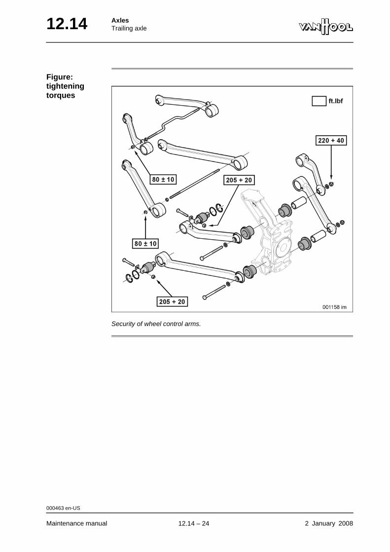
12.14 AxlesTrailing axle
Figure: tightening torques
Security of wheel control arms.
000463 en-US
Maintenance manual 2 January 2008
.
12.14 – 24
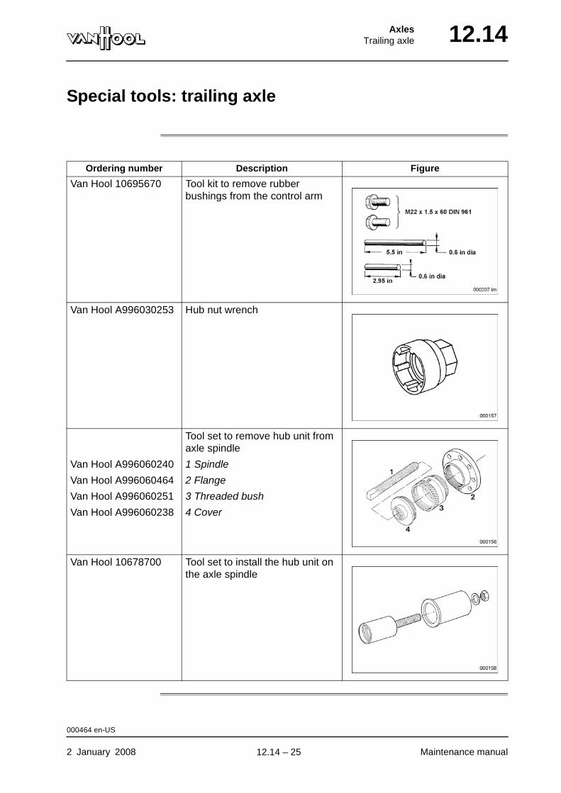
AxlesTrailing axle 12.14
Special tools: trailing axle
Ordering number Description Figure
Van Hool 10695670 Tool kit to remove rubber bushings from the control arm
Van Hool A996030253 Hub nut wrench
Tool set to remove hub unit from axle spindle
Van Hool A996060240 1 Spindle
Van Hool A996060464 2 Flange
Van Hool A996060251 3 Threaded bush
Van Hool A996060238 4 Cover
Van Hool 10678700 Tool set to install the hub unit on the axle spindle
000464 en-US
2 January 2008 Maintenance manual
.
12.14 – 25
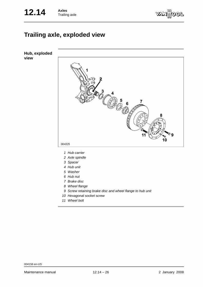
12.14 AxlesTrailing axle
Trailing axle, exploded view
Hub, exploded view
1 Hub carrier2 Axle spindle3 Spacer4 Hub unit5 Washer6 Hub nut7 Brake disc8 Wheel flange9 Screw retaining brake disc and wheel flange to hub unit
10 Hexagonal socket screw11 Wheel bolt
004156 en-US
Maintenance manual 2 January 2008
.
12.14 – 26
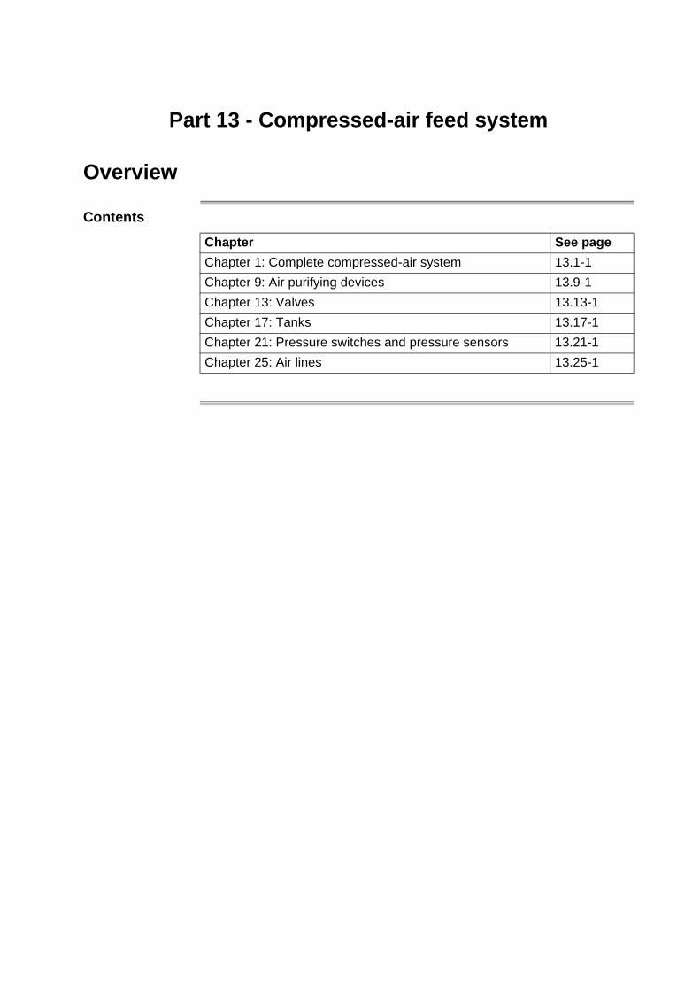
Part 13 - Compressed-air feed system
Overview
Contents
Chapter See page
Chapter 1: Complete compressed-air system 13.1-1
Chapter 9: Air purifying devices 13.9-1
Chapter 13: Valves 13.13-1
Chapter 17: Tanks 13.17-1
Chapter 21: Pressure switches and pressure sensors 13.21-1
Chapter 25: Air lines 13.25-1

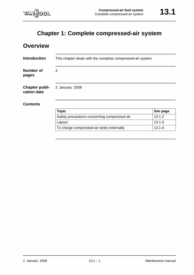
Compressed-air feed systemComplete compressed-air system 13.1
Chapter 1: Complete compressed-air system
Overview
Introduction This chapter deals with the complete compressed-air system.
Number of pages
4
Chapter publi-cation date
2 January 2008
Contents
Topic See page
Safety precautions concerning compressed air 13.1-2
Layout 13.1-3
To charge compressed-air tanks externally 13.1-4
2 January 2008 Maintenance manual
.
13.1 – 1

13.1 Compressed-air feed systemComplete compressed-air system
Safety precautions concerning compressed air
WARNING!Always wear safety goggles, when you are working with compressed air. Never look into a stream of escaping air.
WARNING!It is dangerous to disconnect lines, while the compressed-air system is still pressurized: disconnected lines through which air is escaping can be slung about.
WARNING!Is is dangerous to unscrew plugs or to open compressed-air appara-tuses, while the system is pressurized. Parts that are slung about by compressed air can cause serious injuries.
000538 en-US
Maintenance manual 2 January 2008
.
13.1 – 2
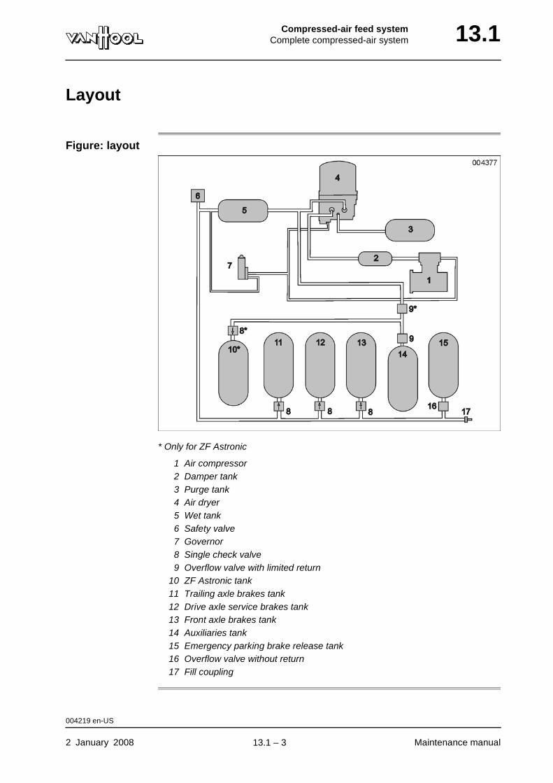
Compressed-air feed systemComplete compressed-air system 13.1
Layout
Figure: layout
* Only for ZF Astronic
1 Air compressor2 Damper tank3 Purge tank4 Air dryer5 Wet tank6 Safety valve7 Governor8 Single check valve9 Overflow valve with limited return
10 ZF Astronic tank11 Trailing axle brakes tank12 Drive axle service brakes tank13 Front axle brakes tank14 Auxiliaries tank15 Emergency parking brake release tank16 Overflow valve without return17 Fill coupling
004219 en-US
2 January 2008 Maintenance manual
.
13.1 – 3
13.1 Compressed-air feed systemComplete compressed-air system
To charge compressed-air tanks externally
CAUTION!Make sure the air is dry and clean. In addition, air pressure should not exceed 130 psi.
Fill coupling As to the location of the fill coupling, refer to "Access doors and controls at the outside".
If necessary, you can charge the entire compressed-air system of the vehicle via the fill coupling.
000035 en-US
Maintenance manual 2 January 2008
.
13.1 – 4
Compressed-air feed systemAir purifying devices 13.9
Chapter 9: Air purifying devices
Overview
Introduction This chapter deals with the air purifying devices.
Number of pages
2
Chapter publi-cation date
2 January 2008
Contents
Topic See page
To change air dryer element 13.9-2
2 January 2008 Maintenance manual
.
13.9 – 1
13.9 Compressed-air feed systemAir purifying devices
To change air dryer element
To be carried out when?
Change the element at the intervals indicated in the maintenance schedule (chapter 1.1) and whenever a check of the compressed-air tanks reveals that there is too much condensation in it.
Equipment condition
• Vehicle on a flat level surface, over an inspection pit;
• Chocks in front of and behind wheels.
Consumables
Location of air dryer
Refer to chapter 1.1, "Maintenance schedule".
Procedure
Air dryer element Van Hool No. 10898619
Step Action
1 Depressurize the air dryer circuit completely by opening the drain valve on the wet tank.
For the location of the air tanks refer to "Location of compressed-air tanks" in chapter 13.17.
2 Wait until no more air escapes from the drain valve.
3 Follow the Haldex instructions provided with the new air dryer element.
004223 en-US
Maintenance manual 2 January 2008
.
13.9 – 2
Compressed-air feed systemValves 13.13
Chapter 13: Valves
Overview
Introduction This chapter deals with the valves.
Number of pages
6
Chapter publi-cation date
2 January 2008
Contents
Topic See page
Visual identification of valves 13.13-2
To check governor operation 13.13-4
Technical data: valves 13.13-5
2 January 2008 Maintenance manual
.
13.13 – 1

13.13 Compressed-air feed systemValves
Visual identification of valves
ComponentsName Figure
Governor
Compressed-air tank drain valve
Pressure-relief valve
Single check valve
004872 en-US
Maintenance manual 2 January 2008
continued on next page.
13.13 – 2
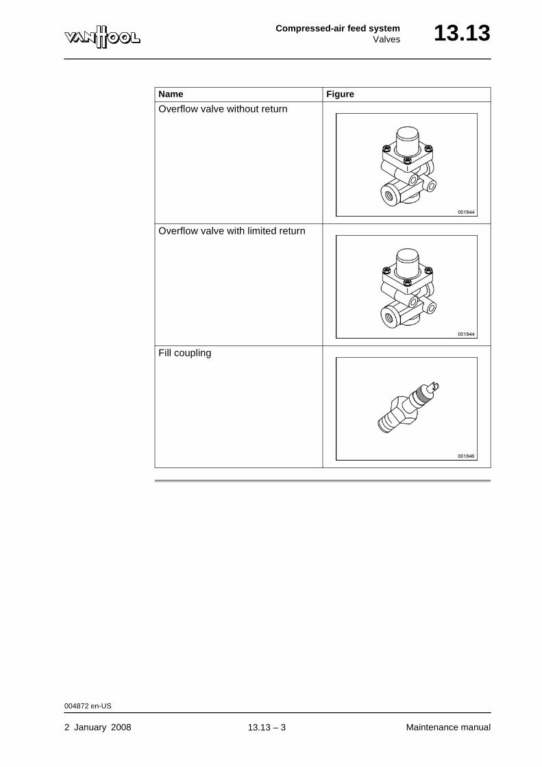
Compressed-air feed systemValves 13.13
Overflow valve without return
Overflow valve with limited return
Fill coupling
Name Figure
004872 en-US
2 January 2008 Maintenance manual
.
13.13 – 3
13.13 Compressed-air feed systemValves
To check governor operation
To be carried out when?
Refer to chapter 1.1, "Maintenance schedule".
Checking values
Refer to "Technical data" at the end of this chapter.
Location of governor
The governor is mounted on the air compressor.
Procedure
Step Action
1 Connect a class 0.6 pressure gauge with a range of 145 psi to the fill coupling of the compressed-air system.
As to the location of the fill coupling, refer to "Access doors and controls at the outside".
2 Start engine to have pressure build-up in compressed-air tanks. Filling should be effected at 1 000 to 1 500 rpm. Follow pressure build-up on the gauge.
3 Make note of pressure reading at point where governor switches off (you will hear air dryer blow off).
4 Compare value with cut-out pressure value in technical data.
5 Have engine idle and keep an eye on pressure gauge. Try and get pressure in tanks to drop back to 105 psi by pumping brake pedal. Wait for a few seconds after each time you have depressed brake pedal.
6 At one point compressor begins to fill compressed-air tanks (gov-ernor cuts in). Make note of pressure gauge reading, exactly at point where pointer starts to climb.
7 Compare value with cut-in pressure value in technical data.
004221 en-US
Maintenance manual 2 January 2008
.
13.13 – 4
Compressed-air feed systemValves 13.13
Technical data: valves
Governor
Make Allied Signal
Type D2
Cut-out pressure 130 to 140 psi
Cut-in pressure 110 to 115 psi
001324 en-US
2 January 2008 Maintenance manual
.
13.13 – 5
13.13 Compressed-air feed systemValves
This page has been intentionally left blank.
001324 en-US
Maintenance manual 2 January 200813.13 – 6
Compressed-air feed systemTanks 13.17
Chapter 17: Tanks
Overview
Introduction This chapter deals with the compressed-air tanks.
Number of pages
4
Chapter publi-cation date
2 January 2008
Contents
Topic See page
Location of compressed-air tanks 13.17-2
To check compressed-air tanks for absence of moisture 13.17-3
To check security of compressed-air tanks 13.17-4
2 January 2008 Maintenance manual
.
13.17 – 1
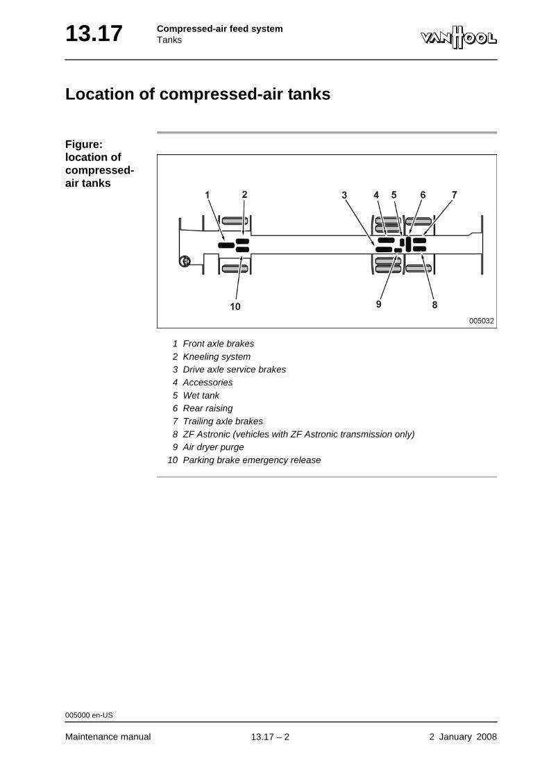
13.17 Compressed-air feed systemTanks
Location of compressed-air tanks
Figure: location of compressed-air tanks
1 Front axle brakes2 Kneeling system3 Drive axle service brakes4 Accessories5 Wet tank6 Rear raising7 Trailing axle brakes8 ZF Astronic (vehicles with ZF Astronic transmission only)9 Air dryer purge
10 Parking brake emergency release
005000 en-US
Maintenance manual 2 January 2008
.
13.17 – 2
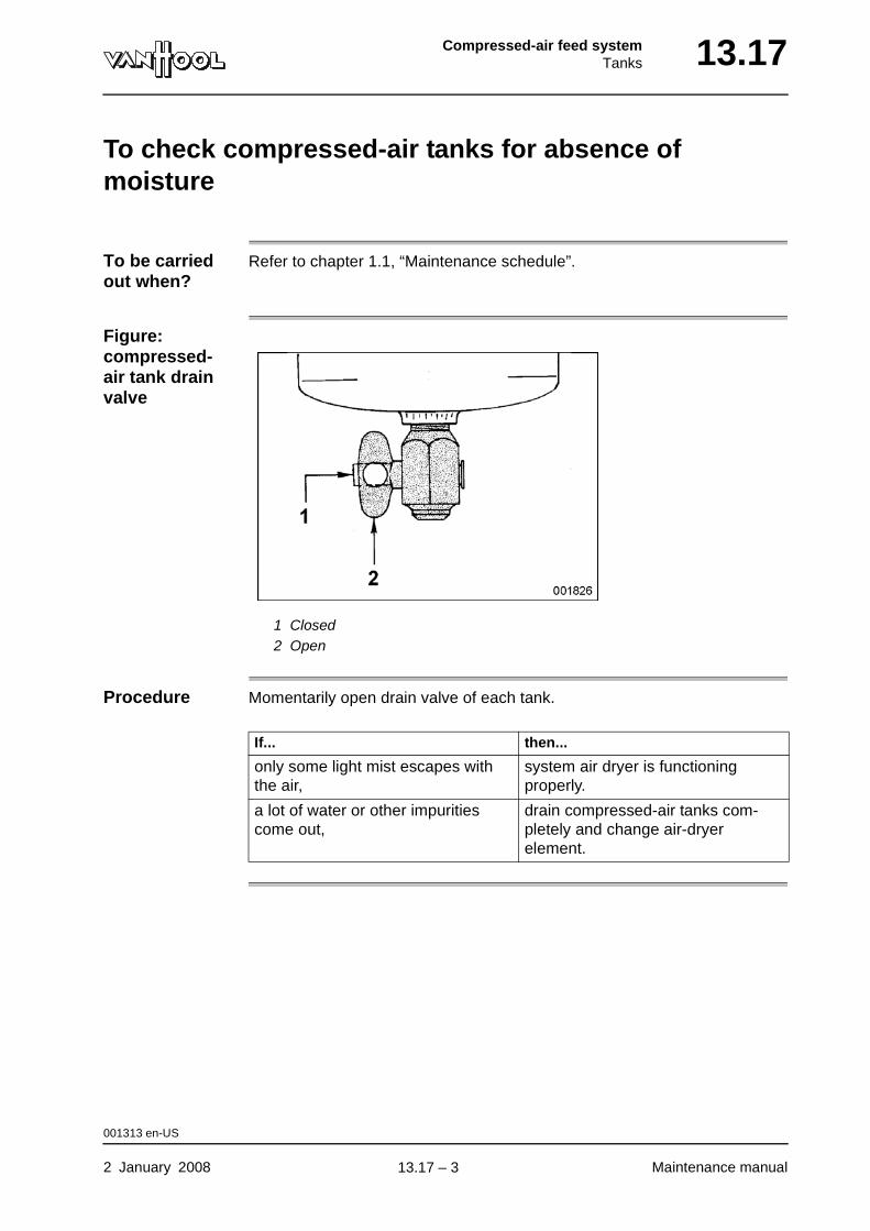
Compressed-air feed systemTanks 13.17
To check compressed-air tanks for absence of moisture
To be carried out when?
Refer to chapter 1.1, “Maintenance schedule”.
Figure: compressed-air tank drain valve
1 Closed2 Open
Procedure Momentarily open drain valve of each tank.
If... then...
only some light mist escapes with the air,
system air dryer is functioning properly.
a lot of water or other impurities come out,
drain compressed-air tanks com-pletely and change air-dryer element.
001313 en-US
2 January 2008 Maintenance manual
.
13.17 – 3
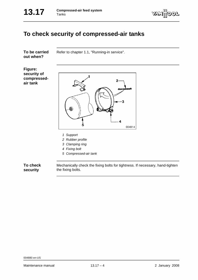
13.17 Compressed-air feed systemTanks
To check security of compressed-air tanks
To be carried out when?
Refer to chapter 1.1, "Running-in service".
Figure: security of compressed-air tank
1 Support2 Rubber profile3 Clamping ring4 Fixing bolt5 Compressed-air tank
To check security
Mechanically check the fixing bolts for tightness. If necessary, hand-tighten the fixing bolts.
004880 en-US
Maintenance manual 2 January 2008
.
13.17 – 4
Compressed-air feed systemPressure switches and pressure sensors 13.21
Chapter 21: Pressure switches and pressure sensors
Overview
Introduction This chapter deals with the pressure switches and pressure sensors.
Number of pages
4
Chapter publi-cation date
2 January 2008
Contents
Topic See page
Visual identification of pressure switches and pressure sensors
13.21-2
2 January 2008 Maintenance manual
.
13.21 – 1
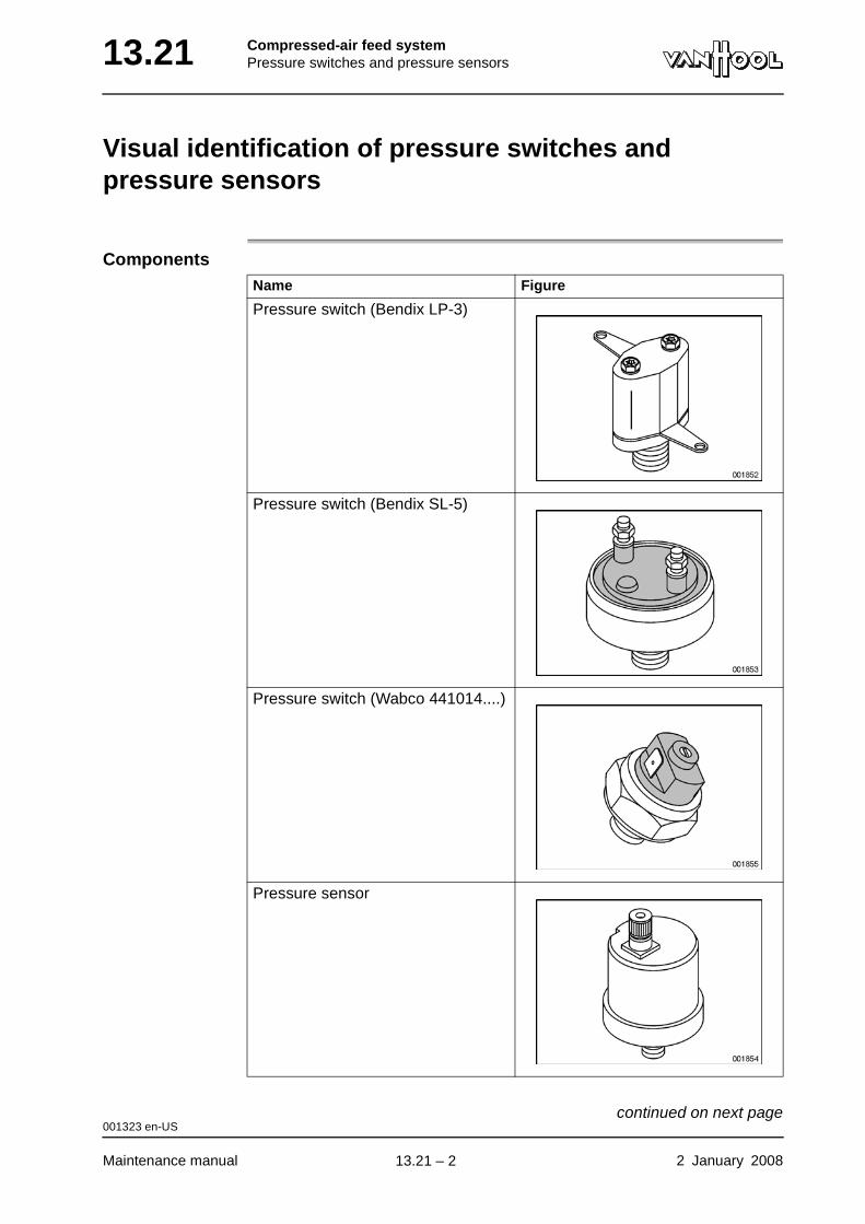
13.21 Compressed-air feed systemPressure switches and pressure sensors
Visual identification of pressure switches and pressure sensors
ComponentsName Figure
Pressure switch (Bendix LP-3)
Pressure switch (Bendix SL-5)
Pressure switch (Wabco 441014....)
Pressure sensor
001323 en-US
Maintenance manual 2 January 2008
continued on next page.
13.21 – 2
Compressed-air feed systemPressure switches and pressure sensors 13.21
001323 en-US
2 January 2008 Maintenance manual
.
13.21 – 3
13.21 Compressed-air feed systemPressure switches and pressure sensors
This page has been intentionally left blank.
001323 en-US
Maintenance manual 2 January 200813.21 – 4
Compressed-air feed systemAir lines 13.25
Chapter 25: Air lines
Overview
Introduction This chapter deals with the air lines.
Number of pages
4
Chapter publi-cation date
2 January 2008
Contents
Topic See page
Air line color codes 13.25-2
To check air-compressor discharge line for carbon deposit 13.25-3
2 January 2008 Maintenance manual
.
13.25 – 1

13.25 Compressed-air feed systemAir lines
Air line color codes
Introduction The end of each air line bears one or two color rings. You can tell by these color rings what is the function of the line. The table below lists the meaning of the colors.
Color codesVan Hool color code Letter representation on
compressed-air diagramFunction
2 x red R-R General pressure supply
1 x red, 1 x green R-GN Tank pressure, service brake 1st axle
1 x green GN Braking pressure, service brake 1st axle
1 x red, 1 x yellow R-GE Tank pressure, service brake 2nd axle
1 x yellow GE Braking pressure, service brake 2nd axle
1 x red, 1 x white R-W Tank pressure, bus stop brake and parking brake
1 x white W Pressure in parking brake cylinders
1 x brown BR Pilot pressure for bus stop brake
1 x red, 1 x gray R-GS Tank pressure, acces-sories
1 x gray GS Accessories (air sus-pension, door control, etc.)
1 x red, 1 x blue R-B Tank pressure, parking brake cylinders emer-gency release
1 x blue B Emergency release pressure for parking brake cylinders
1 x orange O Bleeding
000536 en-US
Maintenance manual 2 January 2008
.
13.25 – 2
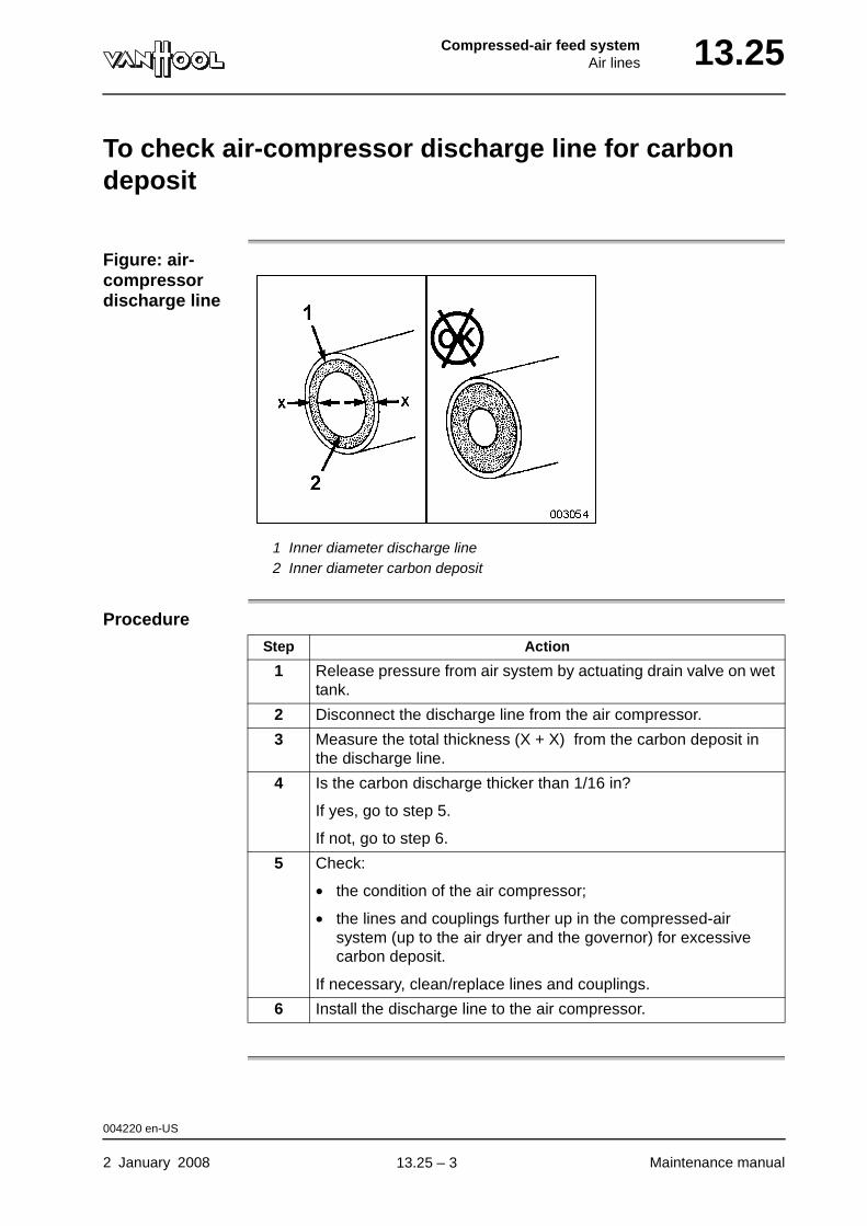
Compressed-air feed systemAir lines 13.25
To check air-compressor discharge line for carbon deposit
Figure: air-compressor discharge line
1 Inner diameter discharge line2 Inner diameter carbon deposit
Procedure
Step Action
1 Release pressure from air system by actuating drain valve on wet tank.
2 Disconnect the discharge line from the air compressor.
3 Measure the total thickness (X + X) from the carbon deposit in the discharge line.
4 Is the carbon discharge thicker than 1/16 in?
If yes, go to step 5.
If not, go to step 6.
5 Check:
• the condition of the air compressor;
• the lines and couplings further up in the compressed-air system (up to the air dryer and the governor) for excessive carbon deposit.
If necessary, clean/replace lines and couplings.
6 Install the discharge line to the air compressor.
004220 en-US
2 January 2008 Maintenance manual
.
13.25 – 3
13.25 Compressed-air feed systemAir lines
This page has been intentionally left blank.
004220 en-US
Maintenance manual 2 January 200813.25 – 4
Part 14 - Electrical
Overview
Contents
Chapter See page
Chapter 2: Electric power supply 14.2-1
Chapter 6: Junction boxes 14.6-1
Chapter 10: Wiring 14.10-1
Chapter 18: Electric circuit diagrams 14.18-1

ElectricalElectric power supply 14.2
Chapter 2: Electric power supply
Overview
Introduction This chapter deals with the electric power supply.
Number of pages
18
Chapter publi-cation date
2 January 2008
Contents
Topic See page
General safety instructions 14.2-2
To retrofit electrical equipment 14.2-3
Alternator: general 14.2-4
Alternator: to carry out a charge test 14.2-6
Alternator: to check alternator brush wear 14.2-7
Alternator: to fit a new or exchange alternator 14.2-9
Safety precautions concerning batteries 14.2-10
Batteries: general 14.2-11
Batteries: general maintenance 14.2-13
Batteries: to check charge 14.2-15
Jump starting instructions 14.2-16
2 January 2008 Maintenance manual
.
14.2 – 1
14.2 ElectricalElectric power supply
General safety instructions
WARNING!The use of mobile phones and transmitting equipment inside the vehicle may disturb the operation of vehicle electronics and therefore jeopardize vehicle operational safety. In order not to jeopardize vehicle operational safety, mobile phones and transmitting equipment must not be used inside the vehicle, unless they are connected to an external vehicle antenna.
CAUTION!Never remove battery clamps while engine is running or with battery switch closed. If you have to remove the battery clamps, always start with the negative terminal (marked with “-” or a blue or green plastic ring). The other way round, always connect the positive terminal first (“+” or red plastic ring), before connecting the negative terminal. Con-necting the wrong polarity will damage the electrical system.
CAUTION!Van Hool cannot be held liable for the consequences of others adding electrical devices or modifying electrical circuits.
CAUTION!Never test an electrical circuit by applying voltage.
CAUTION!Never use an external electrical source to power or test devices on the vehicle.
000207 en-US
Maintenance manual 2 January 2008
.
14.2 – 2
ElectricalElectric power supply 14.2
To retrofit electrical equipment
Introduction If you want to add electrical devices to the vehicle equipment yourself, you should proceed in such a way that the original electrical system is not inter-fered with.
Conditions • To power the additional devices, you will have to fit electrical wires of your own. The wiring you installed yourself will have to be protected with fuses that you will have to provide yourself as well.
• If the combined power consumption of the additional devices exceeds 25 A, you will have to install an additional main fuse with the vehicle bat-teries.
What equipment is allowed?
If electrical or electronic systems are being modified, replaced or added, the devices or systems involved must comply with the requirements outlined in the European directive 72/45/EEC. This directive relates to electromagnetic compatibility (EMC).
001829 en-US
2 January 2008 Maintenance manual
.
14.2 – 3
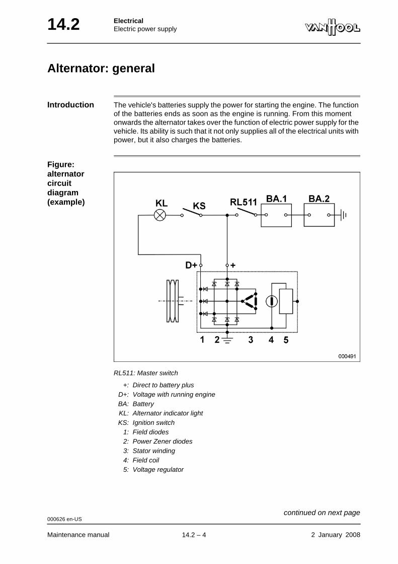
14.2 ElectricalElectric power supply
Alternator: general
Introduction The vehicle's batteries supply the power for starting the engine. The function of the batteries ends as soon as the engine is running. From this moment onwards the alternator takes over the function of electric power supply for the vehicle. Its ability is such that it not only supplies all of the electrical units with power, but it also charges the batteries.
Figure: alternator circuit diagram (example)
RL511: Master switch
+: Direct to battery plusD+: Voltage with running engineBA: BatteryKL: Alternator indicator lightKS: Ignition switch
1: Field diodes2: Power Zener diodes3: Stator winding4: Field coil5: Voltage regulator
000626 en-US
Maintenance manual 2 January 2008
continued on next page.
14.2 – 4
ElectricalElectric power supply 14.2
Parts of the alternator
The three phase current coil (3) is in the stator of the alternator and the field coil (4) is in the rotor. The stator winding (3) is permanently connected with the batteries (BA.1) and (BA.2). The D+ terminal is connected with the field coil through sliprings with carbon brushes. Six Zener diodes (2) serve to rectify the generated three phase alternating current in the stator for usage in the vehicle system. Three ordinary diodes (1) serve to rectify a smaller part of the generated current for feeding the field coil. An electronic voltage regu-lator (5) is under the cap at the end of the alternator.
Operation
Voltage Regulator
The task of the electronic voltage regulator is to upwardly limit the current generated by the alternator, even with strongly varying revolutions and varying load. This limit value is not adjustable. A defective regulator cannot be fixed and must be replaced.
Limitation of voltage peaks
Voltage peaks are limited by the use of Zener diodes as power rectifiers.
Stage Description
1 When the alternator is engaged it cannot power itself. The bat-teries (BA.1) and (BA.2) must power the field coil (4) first of all.
2 With a closed master switch (RL511) and ignition switch (KS) the battery current runs through the alternator indicator light (KL) and the D+ terminal to the field winding (4) through the current regu-lator to the ground.
NOTE: In some vehicles the alternator indicator light is replaced by a simple resistor.
3 The alternator voltage increases as the number of revolutions increases. With this a rectified current runs through the field diodes (1). The voltage difference between the the D+ point and the batteries decreases. Because of this the current that runs through the indicator light (KL) decreases and the latter lights less brightly.
4 As soon as the alternator voltage is of the same value as the battery voltage the indicator light (KL) will go out. All of the field current is then generated by the alternator itself and rectified by the field diodes (1).
5 When the alternator voltage increases even more, the alternator begins to charge the batteries.
000626 en-US
2 January 2008 Maintenance manual
.
14.2 – 5
14.2 ElectricalElectric power supply
Alternator: to carry out a charge test
Equipment condition
Ambient temperature between 65 and 85 °F.
Vehicle with two alter-nators
If your vehicle is equipped with two alternators, it is sometimes difficult, in case of a failure, to determine which alternator is defective. Removing the drive belts of one of the alternators might be helpful in this case.
Procedure
Step Action
1 Before the test, check whether the batteries are in good condition and fully charged. Also check the security of the battery terminal clamps.
2 Connect an accurate voltmeter to the battery group.
3 Let the engine turn at a speed of 1 000 rpm.
4 Connect all current consumers. The voltmeter should now indicate a tension of more than 27 V.
NOTE: If the test is carried out with an engine at operating tem-perature, the charge value is allowed to be 0.5 V lower.
5 If the charge is too low, replace the voltage regulator of the alter-nator and repeat the test.
6 If there is no improvement after carrying out step 5, remove the alternator for repair.
000627 en-US
Maintenance manual 2 January 2008
.
14.2 – 6
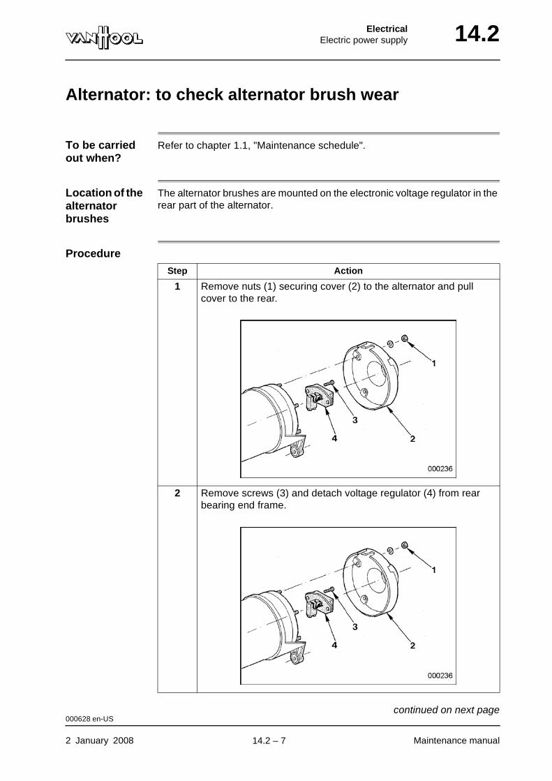
ElectricalElectric power supply 14.2
Alternator: to check alternator brush wear
To be carried out when?
Refer to chapter 1.1, "Maintenance schedule".
Location of the alternator brushes
The alternator brushes are mounted on the electronic voltage regulator in the rear part of the alternator.
Procedure
Step Action
1 Remove nuts (1) securing cover (2) to the alternator and pull cover to the rear.
2 Remove screws (3) and detach voltage regulator (4) from rear bearing end frame.
000628 en-US
2 January 2008 Maintenance manual
continued on next page.
14.2 – 7
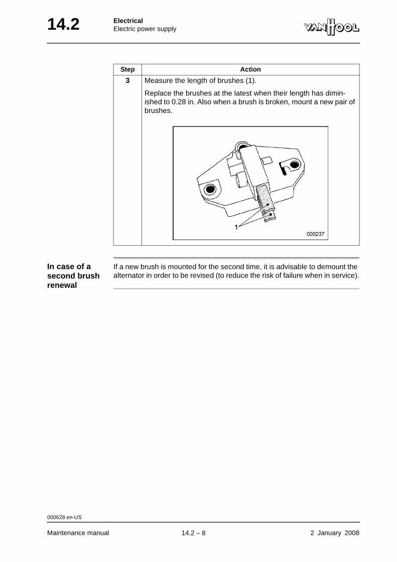
14.2 ElectricalElectric power supply
In case of a second brush renewal
If a new brush is mounted for the second time, it is advisable to demount the alternator in order to be revised (to reduce the risk of failure when in service).
3 Measure the length of brushes (1).
Replace the brushes at the latest when their length has dimin-ished to 0.28 in. Also when a brush is broken, mount a new pair of brushes.
Step Action
000628 en-US
Maintenance manual 2 January 2008
.
14.2 – 8
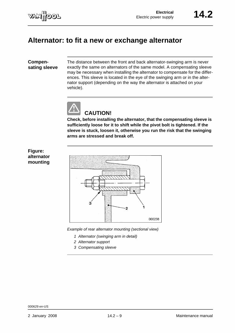
ElectricalElectric power supply 14.2
Alternator: to fit a new or exchange alternator
Compen-sating sleeve
The distance between the front and back alternator-swinging arm is never exactly the same on alternators of the same model. A compensating sleeve may be necessary when installing the alternator to compensate for the differ-ences. This sleeve is located in the eye of the swinging arm or in the alter-nator support (depending on the way the alternator is attached on your vehicle).
CAUTION!Check, before installing the alternator, that the compensating sleeve is sufficiently loose for it to shift while the pivot bolt is tightened. If the sleeve is stuck, loosen it, otherwise you run the risk that the swinging arms are stressed and break off.
Figure: alternator mounting
Example of rear alternator mounting (sectional view)
1 Alternator (swinging arm in detail)2 Alternator support3 Compensating sleeve
000629 en-US
2 January 2008 Maintenance manual
.
14.2 – 9
14.2 ElectricalElectric power supply
Safety precautions concerning batteries
WARNING!Battery fluid is a corrosive acid. Avoid any contact with the eyes, skin, clothing and painted surfaces. In the event of contact, immediately rinse the affected area with ample water; have a doctor attend to the eyes immediately. Avoid spilling battery fluid. Always hold a battery upright, when moving it.
WARNING!Take care that no flames or sparks get in the vicinity of batteries. Do not smoke near batteries. Battery fumes are flammable and explosive. Pro-longed inhalation of these fumes is harmful. Wear gloves and safety goggles. Work in a well-ventilated space.
WARNING!Take care that no metal tools touch the positive battery terminal (or parts attached to it) and the body metal at the same time. After all, this will trigger a short circuit, which can cause burn injuries and explo-sions.
CAUTION!Never remove battery clamps while engine is running or with battery switch closed. If you have to remove the battery clamps, always start with the negative terminal (marked with “-” or a blue or green plastic ring). The other way round, always connect the positive terminal first (“+” or red plastic ring), before connecting the negative terminal. Con-necting the wrong polarity will damage the electrical system.
000621 en-US
Maintenance manual 2 January 2008
.
14.2 – 10
ElectricalElectric power supply 14.2
Batteries: general
Introduction Your vehicle features two 12-volt batteries (or four 6-volt batteries), con-nected in series.
Battery type The batteries are of the "starter battery" type. As the name suggests, this type can only be used to start the engine, i.e. to provide a large supply of energy very briefly. Starter batteries are not appropriate for use that implies extended discharges on a repeated basis. If the battery has to supply power for long periods, its useful life will be greatly reduced.
Role of alternator
The energy taken from the battery to start the engine is recharged by the alternator, while the engine is running.
Disruptions of charging process
If disruptions occur in the charging process, the battery will be recharged inadequately. Insufficient charging for a longer period will cause irretrievable loss of capacity. Disruptions of the charging process can occur, when:
• the vehicle is operated for short trips mainly and the big power consumers are used intensively at the end of the trip; The batteries are not fully recharged, which can cause problems next time you try to start the engine;
• you make a 12-volt tap from the batteries to power a 12-volt system (such as a communications system). The batteries become imbalanced, which will lead to defective batteries in the short run.
• you connect extra devices directly to the batteries. The power used with open battery switch will be greater in this case, which will cause the bat-teries to drain more quickly.
• power is drained with the engine off on a regular basis (for example by turning on interior lighting to clean the vehicle).
With high ambient tem-perature
The batteries of a vehicle that is parked in the garage discharge due to a phe-nomenon known as "self-discharge". In the tropics self-discharge progresses exceptionally fast. After one month without recharging for instance, charge will have dropped to about 50% of normal charge. 50% of normal charge. If the battery discharges even further, it will become unusable on a permanent basis. Therefore, in order to prevent premature loss of batteries, they have to be recharged on a regular basis (by driving the vehicle or using an external battery charger).
Electronic engine control system
Contemporary engines with electronic engine-control systems are very "voltage sensitive": the engine-control electronics do not function, if voltage
000622 en-US
2 January 2008 Maintenance manual
continued on next page.
14.2 – 11

14.2 ElectricalElectric power supply
is too low. In such case starting is impossible, even when the starter motor is running properly.
To recharge batteries from external source
If you have to recharge the battery group with an external source, preferably work with an amperage equaling one tenth of the capacity stated on the bat-teries (expressed in Ah: amp hours). Before charging "low-maintenance" bat-teries, unscrew all plugs to allow for the fumes to escape.
To use a quick charger
Using a so called quick charger is not good for the battery. In general they supply too high an output voltage. If you want to use a quick charger after all, at least remove the clamp from the negative terminal of the battery group before charging. If you neglect to do this, there is a risk of damage to vehicle electronic equipment. As soon as the battery begins to gas, stop quick charging.
Frost protection
Always keep the batteries properly charged. Their frost resistance depends on how well their charging conditions are. A fully charged battery does not freeze until -25 °F, a drained battery on the other hand freezes at 23 °F. Never attempt to charge a battery that is frozen; it has to be defrosted first.
000622 en-US
Maintenance manual 2 January 2008
.
14.2 – 12

ElectricalElectric power supply 14.2
Batteries: general maintenance
To be carried out when?
Refer to chapter 1.1, "Maintenance schedule".
CAUTION!Never disconnect battery terminals, while the engine is running.
Figure: terminals maintenance
Clean and smear terminals with acid-free vaseline.
Procedure
Step Action
1 Switch off master switch.
2 Remove the two terminal clamps (start with negative terminal) and clean them inside and outside with metal brush.
3 Clean battery compartment and top of batteries.
4 Re-attach clamps to terminals (positive clamp first).
5 Brush terminals and clamps with thin layer of acid-free vaseline to combat oxidation.
000623 en-US
2 January 2008 Maintenance manual
continued on next page.
14.2 – 13
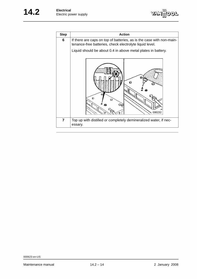
14.2 ElectricalElectric power supply
6 If there are caps on top of batteries, as is the case with non-main-tenance-free batteries, check electrolyte liquid level.
Liquid should be about 0.4 in above metal plates in battery.
7 Top up with distilled or completely demineralized water, if nec-essary.
Step Action
000623 en-US
Maintenance manual 2 January 2008
.
14.2 – 14
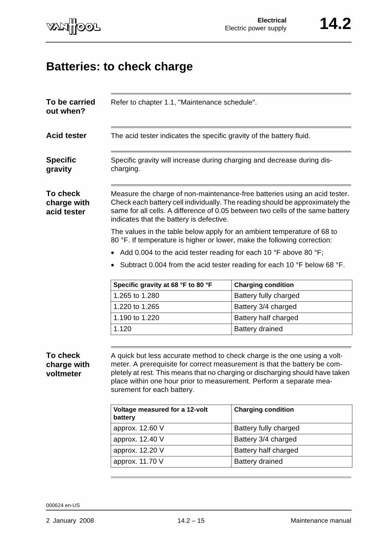
ElectricalElectric power supply 14.2
Batteries: to check charge
To be carried out when?
Refer to chapter 1.1, "Maintenance schedule".
Acid tester The acid tester indicates the specific gravity of the battery fluid.
Specific gravity
Specific gravity will increase during charging and decrease during dis-charging.
To check charge with acid tester
Measure the charge of non-maintenance-free batteries using an acid tester. Check each battery cell individually. The reading should be approximately the same for all cells. A difference of 0.05 between two cells of the same battery indicates that the battery is defective.
The values in the table below apply for an ambient temperature of 68 to 80 °F. If temperature is higher or lower, make the following correction:
• Add 0.004 to the acid tester reading for each 10 °F above 80 °F;
• Subtract 0.004 from the acid tester reading for each 10 °F below 68 °F.
To check charge with voltmeter
A quick but less accurate method to check charge is the one using a volt-meter. A prerequisite for correct measurement is that the battery be com-pletely at rest. This means that no charging or discharging should have taken place within one hour prior to measurement. Perform a separate mea-surement for each battery.
Specific gravity at 68 °F to 80 °F Charging condition
1.265 to 1.280 Battery fully charged
1.220 to 1.265 Battery 3/4 charged
1.190 to 1.220 Battery half charged
1.120 Battery drained
Voltage measured for a 12-volt battery
Charging condition
approx. 12.60 V Battery fully charged
approx. 12.40 V Battery 3/4 charged
approx. 12.20 V Battery half charged
approx. 11.70 V Battery drained
000624 en-US
2 January 2008 Maintenance manual
.
14.2 – 15
14.2 ElectricalElectric power supply
Jump starting instructions
WARNING!Before jump starting through another vehicle, check whether that vehicle has a negative ground 24 volt electrical system. Also check whether the batteries of that vehicle have sufficient capacity. Do not jump start unless both of these conditions have been met. This is nec-essary in order to prevent injuries as well as material damage.
CAUTION!First check fluid level of all batteries. Top up if necessary.
CAUTION!Use jumper cables with a minimum cross section size of 3/0 AWG.
Before connecting jumper cables
First:
• apply parking brake;
• put transmission in neutral;
• stop engine;
• switch off all power consumers;
• turn off vehicle ignition;
• switch off master switch.
NOTE: If jump starting involves the assistance of a host vehicle, these instructions apply to both vehicles.
WARNING!Do not attach jumper cable to pipes or moving parts.
004826 en-US
Maintenance manual 2 January 2008
continued on next page.
14.2 – 16
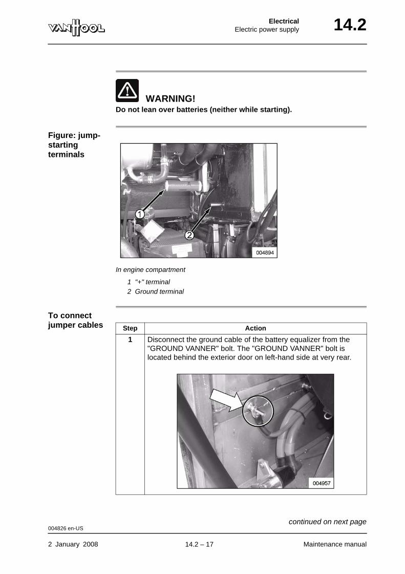
ElectricalElectric power supply 14.2
WARNING!Do not lean over batteries (neither while starting).
Figure: jump-starting terminals
In engine compartment
1 "+" terminal2 Ground terminal
To connect jumper cables Step Action
1 Disconnect the ground cable of the battery equalizer from the "GROUND VANNER" bolt. The "GROUND VANNER" bolt is located behind the exterior door on left-hand side at very rear.
004826 en-US
2 January 2008 Maintenance manual
continued on next page.
14.2 – 17
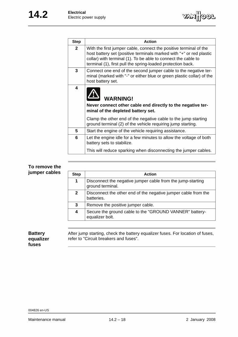
14.2 ElectricalElectric power supply
To remove the jumper cables
Battery equalizer fuses
After jump starting, check the battery equalizer fuses. For location of fuses, refer to "Circuit breakers and fuses".
2 With the first jumper cable, connect the positive terminal of the host battery set (positive terminals marked with "+" or red plastic collar) with terminal (1). To be able to connect the cable to terminal (1), first pull the spring-loaded protection back.
3 Connect one end of the second jumper cable to the negative ter-minal (marked with "-" or either blue or green plastic collar) of the host battery set.
4
WARNING!Never connect other cable end directly to the negative ter-minal of the depleted battery set.
Clamp the other end of the negative cable to the jump starting ground terminal (2) of the vehicle requiring jump starting.
5 Start the engine of the vehicle requiring assistance.
6 Let the engine idle for a few minutes to allow the voltage of both battery sets to stabilize.
This will reduce sparking when disconnecting the jumper cables.
Step Action
Step Action
1 Disconnect the negative jumper cable from the jump-starting ground terminal.
2 Disconnect the other end of the negative jumper cable from the batteries.
3 Remove the positive jumper cable.
4 Secure the ground cable to the "GROUND VANNER" battery-equalizer bolt.
004826 en-US
Maintenance manual 2 January 2008
.
14.2 – 18
ElectricalJunction boxes 14.6
Chapter 6: Junction boxes
Overview
Introduction This chapter deals with the junction boxes.
Number of pages
2
Chapter publi-cation date
2 January 2008
Contents
Topic See page
Location of junction boxes 14.6-2
2 January 2008 Maintenance manual
.
14.6 – 1
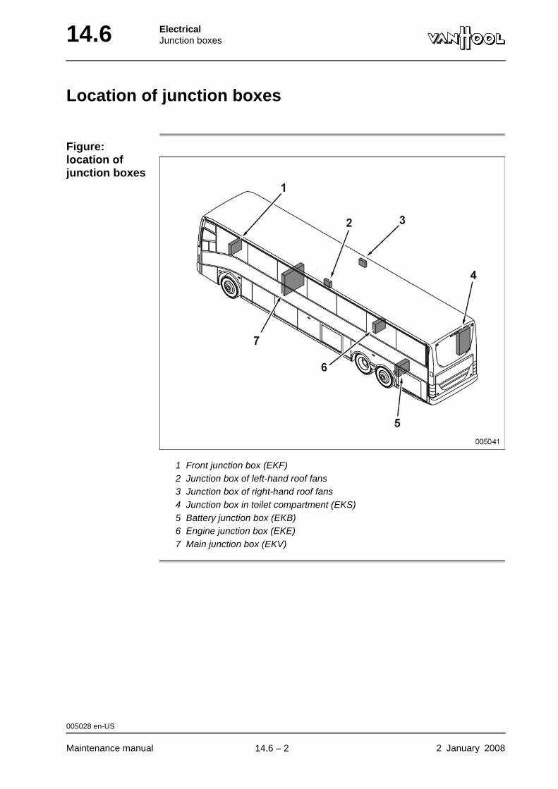
14.6 ElectricalJunction boxes
Location of junction boxes
Figure: location of junction boxes
1 Front junction box (EKF)2 Junction box of left-hand roof fans3 Junction box of right-hand roof fans4 Junction box in toilet compartment (EKS)5 Battery junction box (EKB)6 Engine junction box (EKE)7 Main junction box (EKV)
005028 en-US
Maintenance manual 2 January 2008
.
14.6 – 2
ElectricalWiring 14.10
Chapter 10: Wiring
Overview
Introduction This chapter deals with the wiring.
Number of pages
12
Chapter publi-cation date
2 January 2008
Contents
Topic See page
Battery switch: general 14.10-2
Mechanical battery isolating switch 14.10-5
Circuit breakers and fuses 14.10-6
2 January 2008 Maintenance manual
.
14.10 – 1

14.10 ElectricalWiring
Battery switch: general
Types of battery switches
The two types that may occur are:
• an electric remote-controlled battery relay;
• a mechanically operated battery switch near the batteries.
Figure: remote relay of electric battery switch
Parts of electric battery switch
The electric battery switch consists of a remote relay near the batteries, which is operated by a switch on the dashboard. Depending on vehicle model the operating switch is either the key contact or a separate switch.
000625 en-US
Maintenance manual 2 January 2008
continued on next page.
14.10 – 2
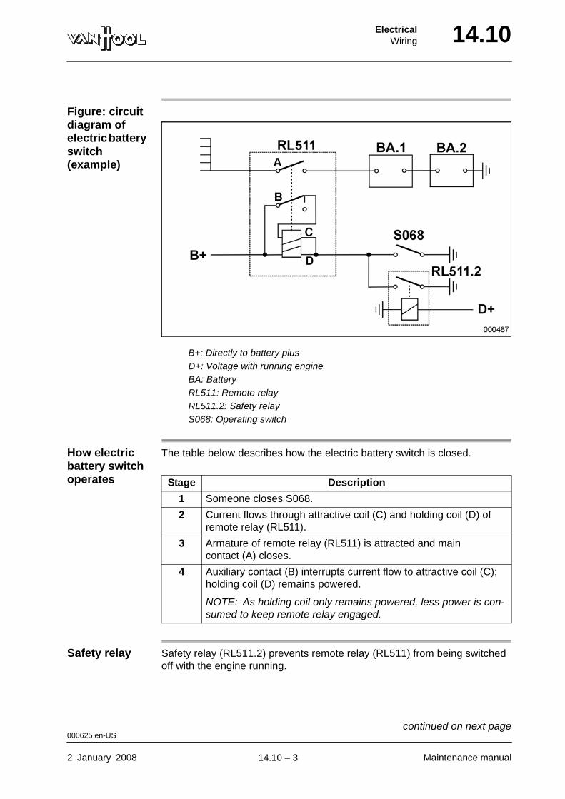
ElectricalWiring 14.10
Figure: circuit diagram of electric battery switch (example)
B+: Directly to battery plusD+: Voltage with running engineBA: BatteryRL511: Remote relayRL511.2: Safety relayS068: Operating switch
How electric battery switch operates
The table below describes how the electric battery switch is closed.
Safety relay Safety relay (RL511.2) prevents remote relay (RL511) from being switched off with the engine running.
Stage Description
1 Someone closes S068.
2 Current flows through attractive coil (C) and holding coil (D) of remote relay (RL511).
3 Armature of remote relay (RL511) is attracted and main contact (A) closes.
4 Auxiliary contact (B) interrupts current flow to attractive coil (C); holding coil (D) remains powered.
NOTE: As holding coil only remains powered, less power is con-sumed to keep remote relay engaged.
000625 en-US
2 January 2008 Maintenance manual
continued on next page.
14.10 – 3
14.10 ElectricalWiring
Cut-off delay Some vehicles have a delay circuit that triggers a cut-off delay after (S068) has been opened. This time is needed for the self-testing of electronic con-trols such as EDC.
000625 en-US
Maintenance manual 2 January 2008
.
14.10 – 4
ElectricalWiring 14.10
Mechanical battery isolating switch
Introduction With the mechanical battery isolating switch, it is possible to immediately cut off all current consumers in your vehicle, including the consumers with "B+" power supply (which is impossible with the electrical battery isolating switch, see operating manual, chapter 5, under "To operate the battery isolating switch").
Location of mechanical battery isolating switch
Refer to chapter 1.1, under "Access doors and controls at the outside".
Pay attention to what before opening the mechanical battery isolating switch?
Take the following precautions into account to avoid damage to the vehicle alternator or deranging any electronic systems.
CAUTION!Never open the mechanical battery isolating switch while the engine is running.
CAUTION!Never open the mechanical battery switch, when the electrical battery switch is on.
CAUTION!After switching off the electric battery isolating switch, wait until the on-board voltage is cut off before opening the mechanical battery isolating switch.
003743 en-US
2 January 2008 Maintenance manual
.
14.10 – 5
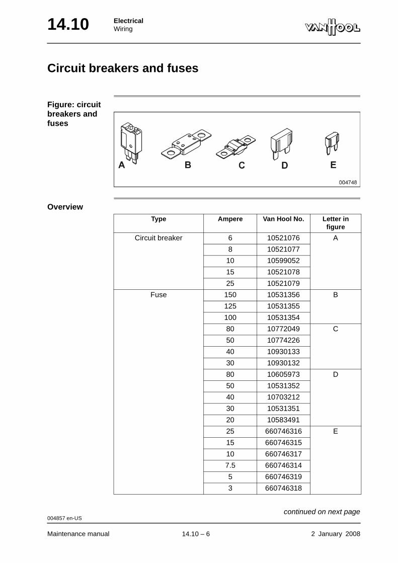
14.10 ElectricalWiring
Circuit breakers and fuses
Figure: circuit breakers and fuses
OverviewType Ampere Van Hool No. Letter in
figure
Circuit breaker 6 10521076 A
8 10521077
10 10599052
15 10521078
25 10521079
Fuse 150 10531356 B
125 10531355
100 10531354
80 10772049 C
50 10774226
40 10930133
30 10930132
80 10605973 D
50 10531352
40 10703212
30 10531351
20 10583491
25 660746316 E
15 660746315
10 660746317
7.5 660746314
5 660746319
3 660746318
004857 en-US
Maintenance manual 2 January 2008
continued on next page.
14.10 – 6
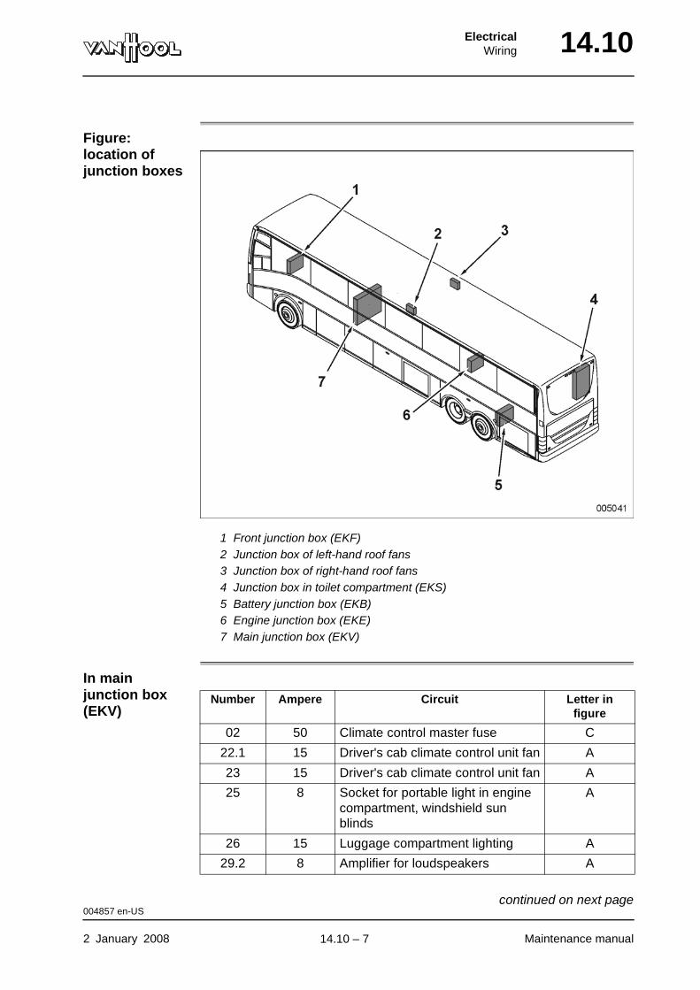
ElectricalWiring 14.10
Figure: location of junction boxes
1 Front junction box (EKF)2 Junction box of left-hand roof fans3 Junction box of right-hand roof fans4 Junction box in toilet compartment (EKS)5 Battery junction box (EKB)6 Engine junction box (EKE)7 Main junction box (EKV)
In main junction box (EKV)
Number Ampere Circuit Letter in figure
02 50 Climate control master fuse C
22.1 15 Driver's cab climate control unit fan A
23 15 Driver's cab climate control unit fan A
25 8 Socket for portable light in engine compartment, windshield sun blinds
A
26 15 Luggage compartment lighting A
29.2 8 Amplifier for loudspeakers A
004857 en-US
2 January 2008 Maintenance manual
continued on next page.
14.10 – 7

14.10 ElectricalWiring
32 10 ABS system A
33 10 ABS system A
35 8 Guide reading light, video box lighting
A
36 8 Exterior mirrors adjustment A
37 8 ZF-Intarder A
38 8 Guide seat A
39 8 Reference voltage, cigarette lighter A
42 8 Trip computer (Cummins), starter motor, EDC engine management system, high idle safety circuit, Jake Brake (Caterpillar)
A
43 3 Trip computer (Detroit Diesel) E
44 15 Refrigerator A
46.1 8 Toilet, flash light and buzzer at pas-senger door to indicate that the vehicle is raising/lowering, raising/lowering system
A
47 8 12 volt master relay, exterior lighting, battery equalizer
A
49 8 Engine diagnostics socket (Cummins)
A
80 8 Emergency switch A
81.1 10 Hazard warning flasher, trip com-puter (Cummins), engine diag-nostics socket (Cummins)
A
81.2 10 Turn signals, master switch A
82 8 Digital clock, coolant heater pro-grammable control
A
83.2 15 Coolant heater A
84.1 8 Multiplex system computer module A
85 8 Dashboard node A
95 8 Low beam, right-hand A
96 8 Low beam, left-hand A
97 8 High beam, right-hand A
98 8 High beam, left-hand A
130 50 Node 1 C
131 8 Driver's cab climate control unit A
151 30 12 volt master fuse C
Number Ampere Circuit Letter in figure
004857 en-US
Maintenance manual 2 January 2008
continued on next page.
14.10 – 8

ElectricalWiring 14.10
In toilet com-partment junction box (EKS)
152 8 Radio communication system socket (12 volt), trip computer (Detroit Diesel)
A
153 15 Audio/video (12 volt) A
154 10 Audio/video E
155 10 Flash light and buzzer at pas-senger door to indicate that the vehicle is raising/lowering, audio/video (12 volt), back-up camera
E
156 3 Antenna amplifier E
158 15 Front fog lamps E
159 8 Radio communication system socket (12 volt)
A
185 8 Passenger door, luggage com-partment central locking system
A
200 15 Node 2 A
201 15 Node 2 A
202 15 Node 2 A
203 15 Node 2 A
204 15 Node 2 A
300 15 Node 3 A
301 15 Node 3 A
302 15 Node 3 A
303 15 Node 3 A
304 15 Node 3 A
F21M 10 Climate control A
F22M 10 Climate control A
F23M 10 Climate control A
F24M 10 Climate control A
F25M 10 Climate control A
F26M 10 Climate control A
Number Ampere Circuit Letter in figure
Number Ampere Circuit Letter in figure
05 100 Wheelchair lift B
08 125 Kitchenette B
400 15 Node 4 A
004857 en-US
2 January 2008 Maintenance manual
continued on next page.
14.10 – 9
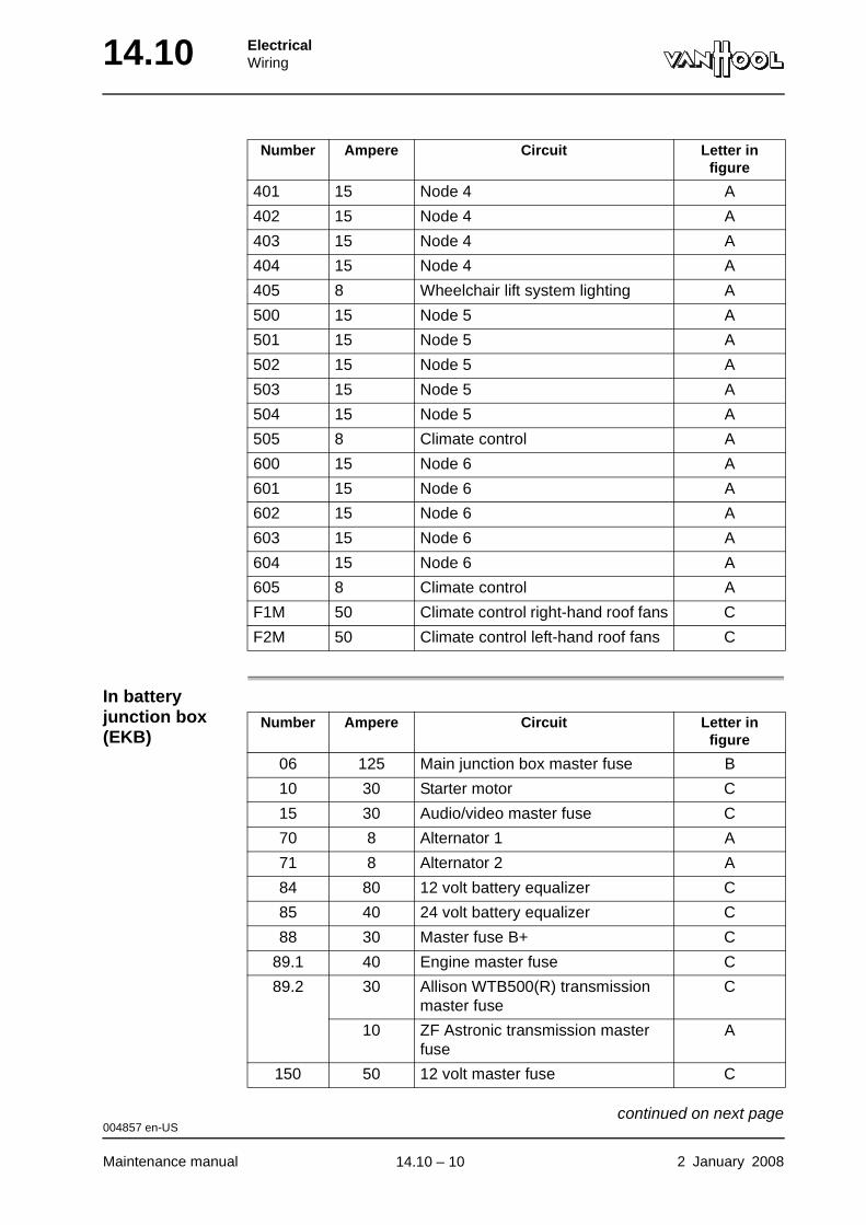
14.10 ElectricalWiring
In battery junction box (EKB)
401 15 Node 4 A
402 15 Node 4 A
403 15 Node 4 A
404 15 Node 4 A
405 8 Wheelchair lift system lighting A
500 15 Node 5 A
501 15 Node 5 A
502 15 Node 5 A
503 15 Node 5 A
504 15 Node 5 A
505 8 Climate control A
600 15 Node 6 A
601 15 Node 6 A
602 15 Node 6 A
603 15 Node 6 A
604 15 Node 6 A
605 8 Climate control A
F1M 50 Climate control right-hand roof fans C
F2M 50 Climate control left-hand roof fans C
Number Ampere Circuit Letter in figure
Number Ampere Circuit Letter in figure
06 125 Main junction box master fuse B
10 30 Starter motor C
15 30 Audio/video master fuse C
70 8 Alternator 1 A
71 8 Alternator 2 A
84 80 12 volt battery equalizer C
85 40 24 volt battery equalizer C
88 30 Master fuse B+ C
89.1 40 Engine master fuse C
89.2 30 Allison WTB500(R) transmission master fuse
C
10 ZF Astronic transmission master fuse
A
150 50 12 volt master fuse C
004857 en-US
Maintenance manual 2 January 2008
continued on next page.
14.10 – 10
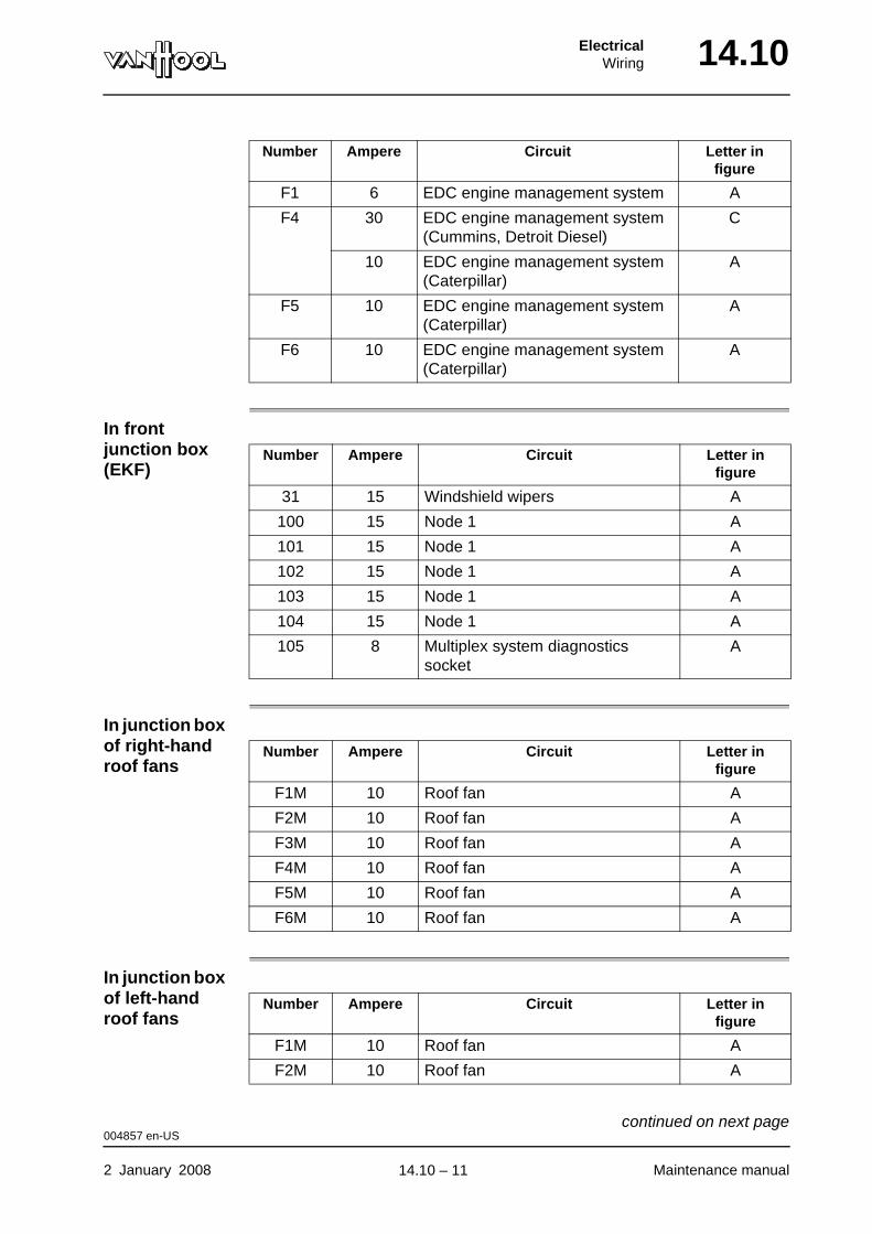
ElectricalWiring 14.10
In front junction box (EKF)
In junction box of right-hand roof fans
In junction box of left-hand roof fans
F1 6 EDC engine management system A
F4 30 EDC engine management system (Cummins, Detroit Diesel)
C
10 EDC engine management system (Caterpillar)
A
F5 10 EDC engine management system (Caterpillar)
A
F6 10 EDC engine management system (Caterpillar)
A
Number Ampere Circuit Letter in figure
Number Ampere Circuit Letter in figure
31 15 Windshield wipers A
100 15 Node 1 A
101 15 Node 1 A
102 15 Node 1 A
103 15 Node 1 A
104 15 Node 1 A
105 8 Multiplex system diagnostics socket
A
Number Ampere Circuit Letter in figure
F1M 10 Roof fan A
F2M 10 Roof fan A
F3M 10 Roof fan A
F4M 10 Roof fan A
F5M 10 Roof fan A
F6M 10 Roof fan A
Number Ampere Circuit Letter in figure
F1M 10 Roof fan A
F2M 10 Roof fan A
004857 en-US
2 January 2008 Maintenance manual
continued on next page.
14.10 – 11
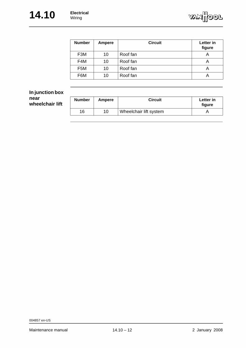
14.10 ElectricalWiring
In junction box near wheelchair lift
F3M 10 Roof fan A
F4M 10 Roof fan A
F5M 10 Roof fan A
F6M 10 Roof fan A
Number Ampere Circuit Letter in figure
Number Ampere Circuit Letter in figure
16 10 Wheelchair lift system A
004857 en-US
Maintenance manual 2 January 2008
.
14.10 – 12
ElectricalElectric circuit diagrams 14.18
Chapter 18: Electric circuit diagrams
Overview
Introduction This chapter deals with the electric circuit diagrams.
Number of pages
16
Chapter publi-cation date
2 January 2008
Contents
Topic See page
Electrical wiring diagram booklet 14.18-2
Subdiagrams 14.18-4
Components 14.18-7
Power supply 14.18-11
Situation to which diagram applies 14.18-12
Electrical wires 14.18-13
Cross-references 14.18-15
Connector designation 14.18-16
2 January 2008 Maintenance manual
.
14.18 – 1
14.18 ElectricalElectric circuit diagrams
Electrical wiring diagram booklet
Introduction For convenience purposes the electrical wiring diagram for your vehicle has been divided into subdiagrams on A4 format. Each subdiagram combines a number of electrical components, the function of which is related. The subdi-agrams have been compiled into an “Electrical wiring diagram booklet”, which is supplied separately with the vehicle.
Data on front page of wiring diagram booklet
The front page of the wiring diagram booklet contains the following data:
• Name of the vehicle model the wiring diagram booklet applies to;
• Publication date;
• Production number(s) of the vehicle – or the vehicle model series – the wiring diagram booklet applies to.
NOTE: Before using the wiring diagram booklet, check the data on the front page so as to make sure the booklet you are holding actually goes with your vehicle.
000724 en-US
Maintenance manual 2 January 2008
continued on next page.
14.18 – 2
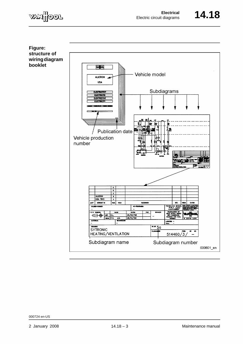
ElectricalElectric circuit diagrams 14.18
Figure: structure of wiring diagram booklet
000724 en-US
2 January 2008 Maintenance manual
.
14.18 – 3
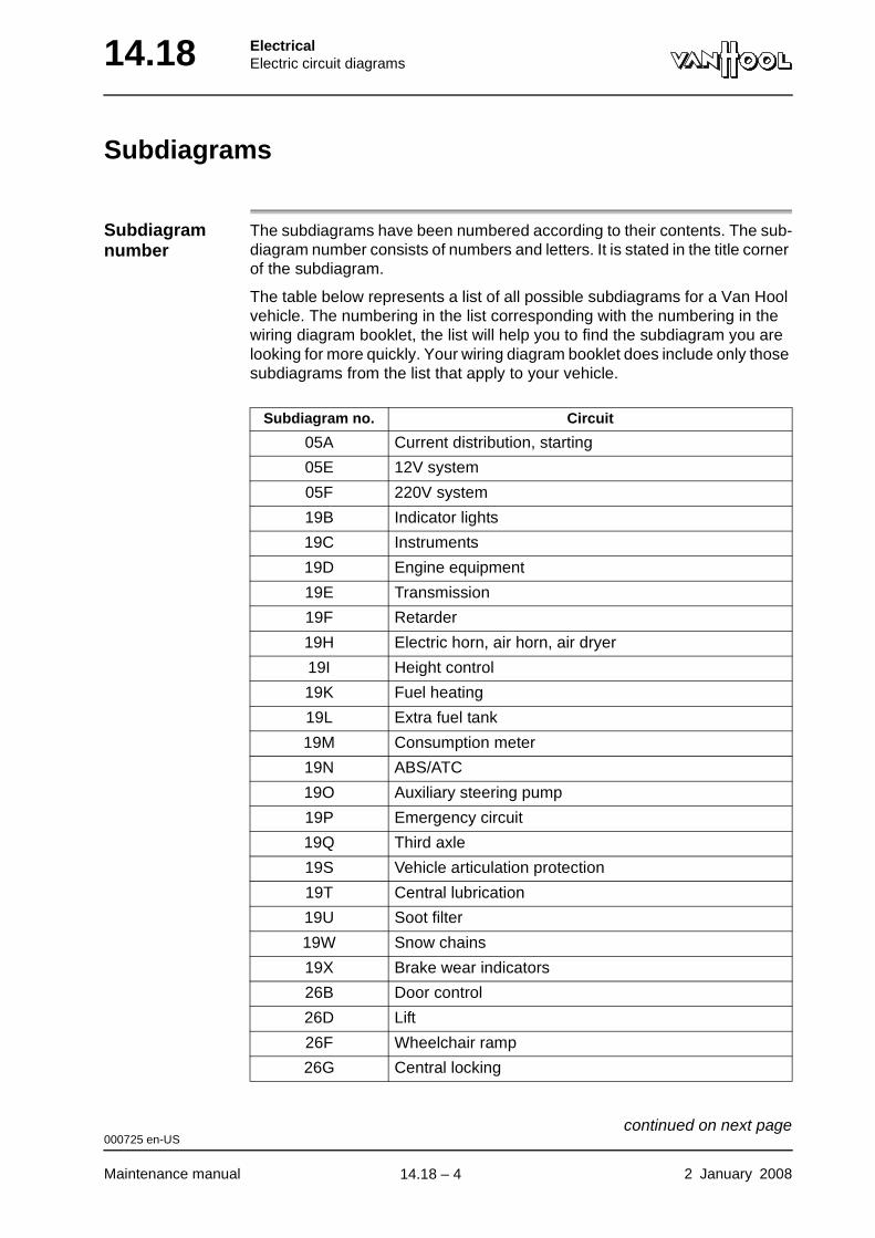
14.18 ElectricalElectric circuit diagrams
Subdiagrams
Subdiagram number
The subdiagrams have been numbered according to their contents. The sub-diagram number consists of numbers and letters. It is stated in the title corner of the subdiagram.
The table below represents a list of all possible subdiagrams for a Van Hool vehicle. The numbering in the list corresponding with the numbering in the wiring diagram booklet, the list will help you to find the subdiagram you are looking for more quickly. Your wiring diagram booklet does include only those subdiagrams from the list that apply to your vehicle.
Subdiagram no. Circuit
05A Current distribution, starting
05E 12V system
05F 220V system
19B Indicator lights
19C Instruments
19D Engine equipment
19E Transmission
19F Retarder
19H Electric horn, air horn, air dryer
19I Height control
19K Fuel heating
19L Extra fuel tank
19M Consumption meter
19N ABS/ATC
19O Auxiliary steering pump
19P Emergency circuit
19Q Third axle
19S Vehicle articulation protection
19T Central lubrication
19U Soot filter
19W Snow chains
19X Brake wear indicators
26B Door control
26D Lift
26F Wheelchair ramp
26G Central locking
000725 en-US
Maintenance manual 2 January 2008
continued on next page.
14.18 – 4

ElectricalElectric circuit diagrams 14.18
26H Driver's gate
26U Door 1
26V Door 2
26W Door 3
26X Door 4
30A Route indicators
30B Payment system
30C Counting system
36A Exterior lighting
36B Turn signals
36D Alarm systems
36F Ski box lighting
37A Interior lighting
37B Digital clock, cigarette lighter, interior accessories
37D Driver's sleeping compartment
37E Crew call system, stop request
38A Windshield wipers and washer
40A Public address system
40B Audio, video
40C Speakers
40D Intercom
40E Camera system
40F Communication system
40G Navigation system
42A Adjustable mirrors
44A Toilet
44B Water heater, oven
45A Refrigerator
46A Electric driver's window
46B Heated windshield (top)
46C Electric roof hatches
50A Heating, ventilation
50B Interior heating
50C Roof heating
50D Temperature gauges
50E Climate control
50F Driver's climate unit
Subdiagram no. Circuit
000725 en-US
2 January 2008 Maintenance manual
continued on next page.
14.18 – 5
14.18 ElectricalElectric circuit diagrams
000725 en-US
Maintenance manual 2 January 2008
.
14.18 – 6
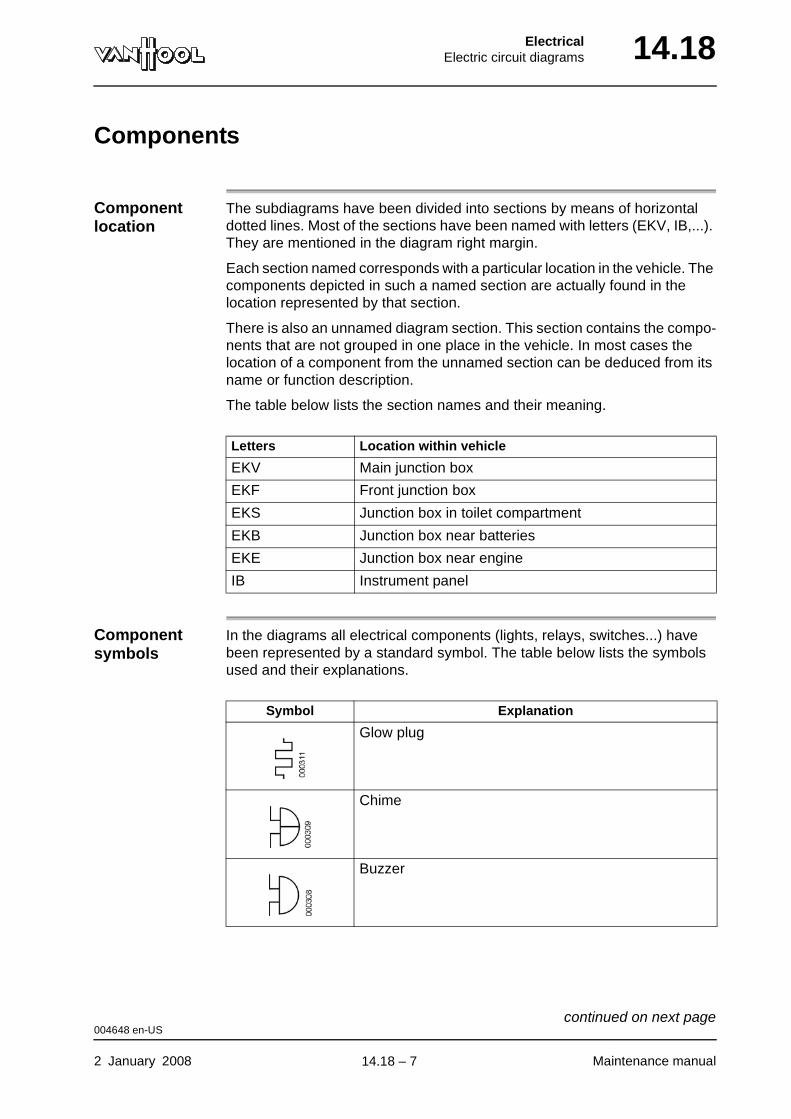
ElectricalElectric circuit diagrams 14.18
Components
Component location
The subdiagrams have been divided into sections by means of horizontal dotted lines. Most of the sections have been named with letters (EKV, IB,...). They are mentioned in the diagram right margin.
Each section named corresponds with a particular location in the vehicle. The components depicted in such a named section are actually found in the location represented by that section.
There is also an unnamed diagram section. This section contains the compo-nents that are not grouped in one place in the vehicle. In most cases the location of a component from the unnamed section can be deduced from its name or function description.
The table below lists the section names and their meaning.
Component symbols
In the diagrams all electrical components (lights, relays, switches...) have been represented by a standard symbol. The table below lists the symbols used and their explanations.
Letters Location within vehicle
EKV Main junction box
EKF Front junction box
EKS Junction box in toilet compartment
EKB Junction box near batteries
EKE Junction box near engine
IB Instrument panel
Symbol Explanation
Glow plug
Chime
Buzzer
004648 en-US
2 January 2008 Maintenance manual
continued on next page.
14.18 – 7
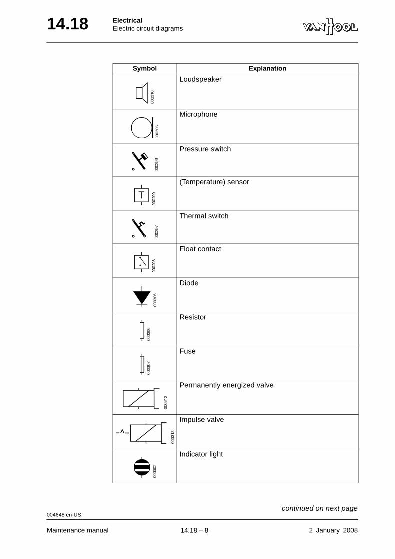
14.18 ElectricalElectric circuit diagrams
Loudspeaker
Microphone
Pressure switch
(Temperature) sensor
Thermal switch
Float contact
Diode
Resistor
Fuse
Permanently energized valve
Impulse valve
Indicator light
Symbol Explanation
004648 en-US
Maintenance manual 2 January 2008
continued on next page.
14.18 – 8
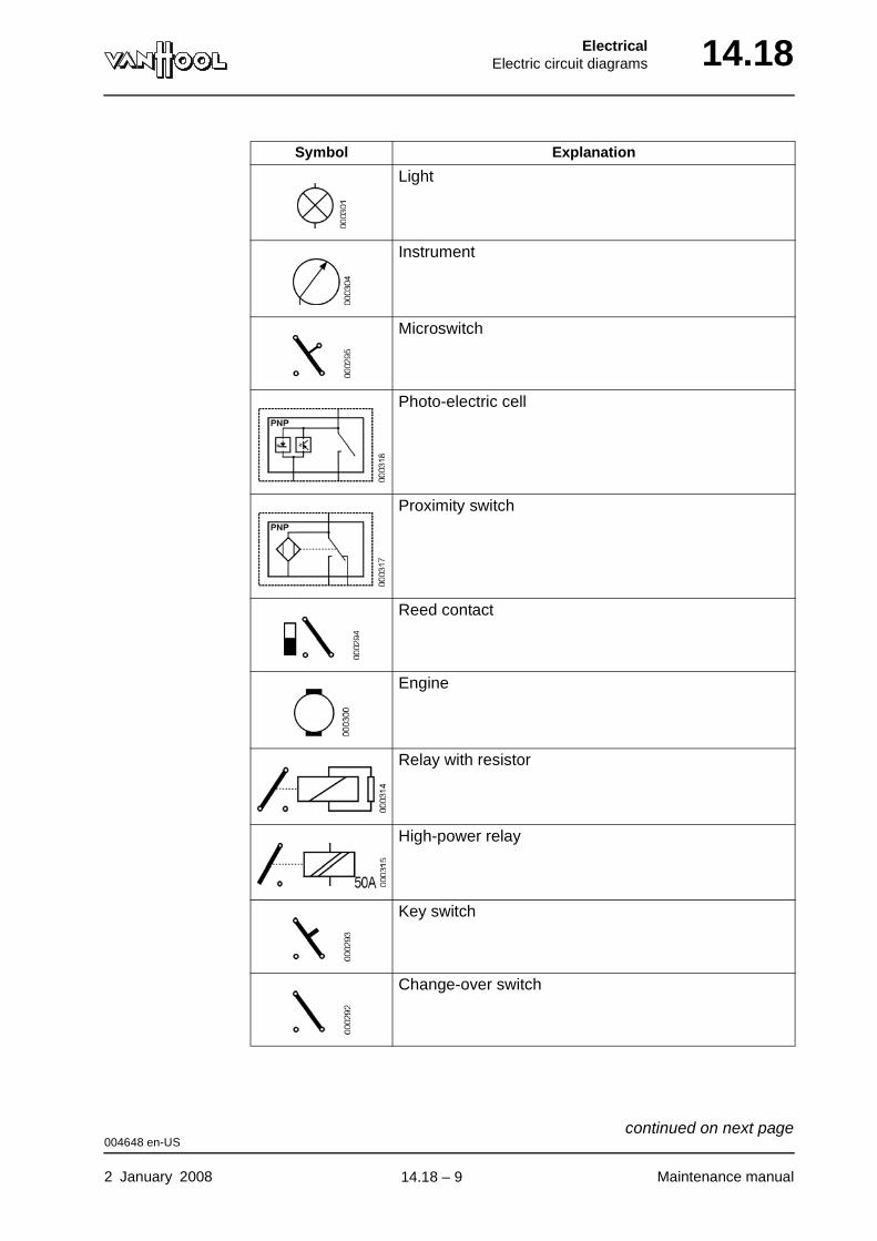
ElectricalElectric circuit diagrams 14.18
Light
Instrument
Microswitch
Photo-electric cell
Proximity switch
Reed contact
Engine
Relay with resistor
High-power relay
Key switch
Change-over switch
Symbol Explanation
004648 en-US
2 January 2008 Maintenance manual
continued on next page.
14.18 – 9
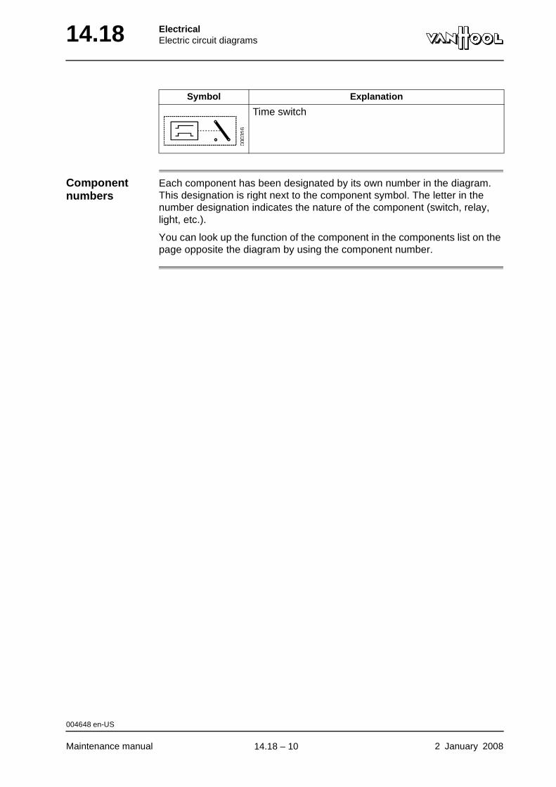
14.18 ElectricalElectric circuit diagrams
Component numbers
Each component has been designated by its own number in the diagram. This designation is right next to the component symbol. The letter in the number designation indicates the nature of the component (switch, relay, light, etc.).
You can look up the function of the component in the components list on the page opposite the diagram by using the component number.
Time switch
Symbol Explanation
004648 en-US
Maintenance manual 2 January 2008
.
14.18 – 10
ElectricalElectric circuit diagrams 14.18
Power supply
Designation of power supply
In the drawings power circuits start at the top, with the circuit fuse. The des-ignation of the power connection is found at the starting point of the circuit (B+, +30...). Thus you can see the path along which the circuit is connected to the power source (battery, alternator), which allows you to know, when it is conducting.
The table below lists the distinguishing marks of the power connection.
Connection mark Explanation
B+ Direct to battery plus. The circuit is always live with power. Used for coolant heater, hazard warning flashers, memory of electronic control units.
+30 Voltage after battery switch. Used for all body equipment, such as: climate control, lighting, audio system.
+15 Voltage after turning on ignition. Used for all compo-nents that are important for driving.
D+ Voltage with running engine. Used for circuits with high-power equipment, to spare batteries.
+58 Voltage with side marker lights turned on.
+56 Voltage with low beam or high beam lights turned on.
000727 en-US
2 January 2008 Maintenance manual
.
14.18 – 11
14.18 ElectricalElectric circuit diagrams
Situation to which diagram applies
Rest state Some component symbols have been conceived in such a way that the position of the symbol parts represents the state the component is in (switch on or off, relay powered or not...). Symbols in Van Hool diagrams always rep-resent the position that corresponds with vehicle rest state. The conditions for this rest state are:
• batteries disconnected;
• 115 psi pressure in compressed-air tanks;
• all doors and hatches closed;
• transmission in neutral;
• all brakes released;
• engine off;
• all systems switched off, control switches in rest position;
• temperature 70 °F.
000728 en-US
Maintenance manual 2 January 2008
.
14.18 – 12
ElectricalElectric circuit diagrams 14.18
Electrical wires
Wire colors Van Hool use differently colored electrical wires to connect junction boxes and devices. There are wires with single-color insulation and wires with two-color insulation. The two-color wires have a strip lengthwise in a contrasting color running over the main color of the insulation material.
In the diagram the connection represented bears a letter code, which refers to the wire color. The table below lists the meaning of the colors.
If a wire has two colors, this is indicated in the diagram as follows:
GE-R= yellow wire with red stripe
NOTE: Nowadays the regular color for ground wires is brown. In older vehicles, however, black ground wire has been used.
Wire cross-section
The diagram mentions the wire section, expressed in square millimeters (mm2), after the wire color code. If the section is not mentioned, it is 1 mm2 (in older vehicles: 1.5 mm2).
Example:
BR2.5 = brown wire with 2.5 mm2 section
“American Wire Gauge (AWG)”
Consult the table below, when using "AWG" electrical wires when replacing electrical wires.
Letter code Wire color
Z Black
BR Brown
R Red
O Orange
GE Yellow
GN Green
B Blue
V Violet
GS Gray
W white
T Transparent
RO Pink
000729 en-US
2 January 2008 Maintenance manual
continued on next page.
14.18 – 13
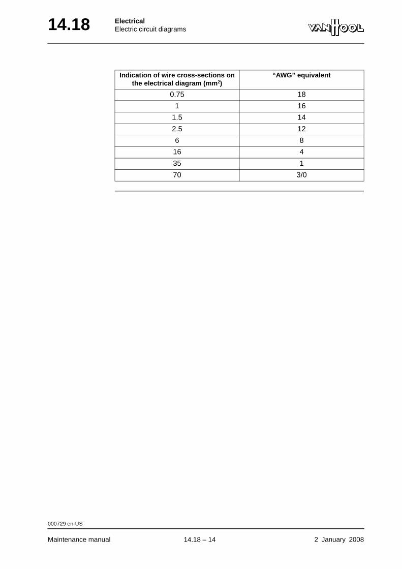
14.18 ElectricalElectric circuit diagrams
Indication of wire cross-sections on the electrical diagram (mm2)
“AWG” equivalent
0.75 18
1 16
1.5 14
2.5 12
6 8
16 4
35 1
70 3/0
000729 en-US
Maintenance manual 2 January 2008
.
14.18 – 14
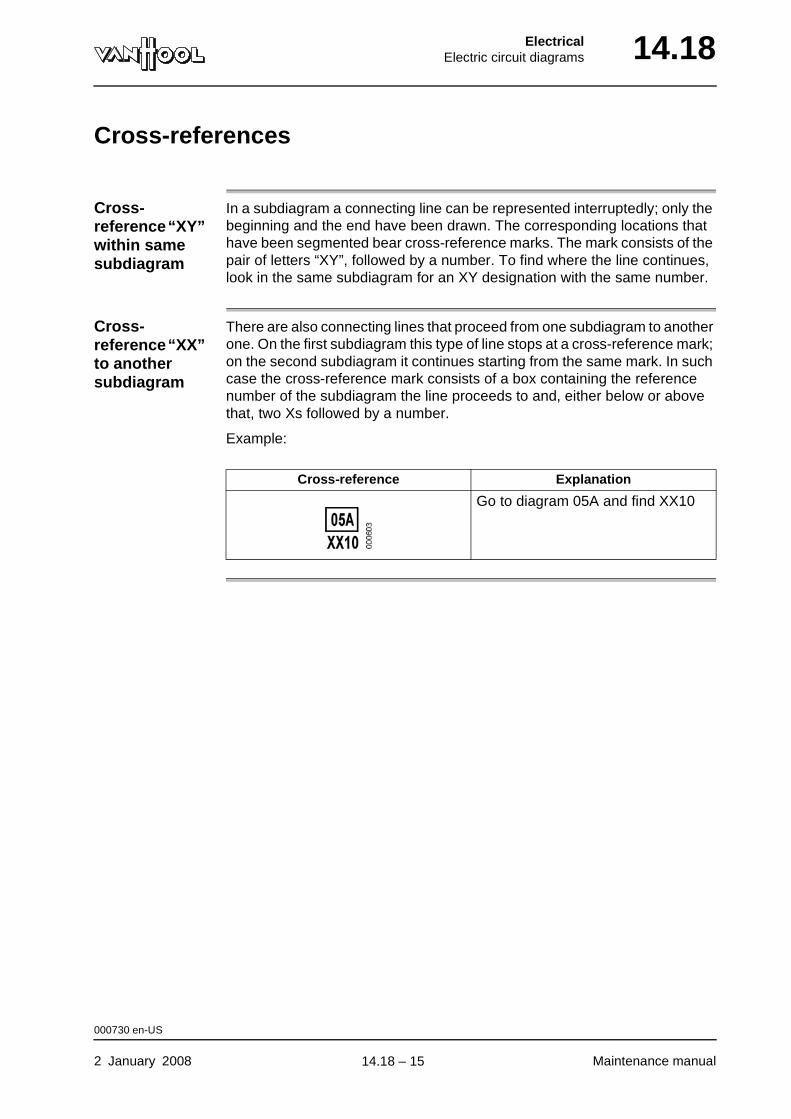
ElectricalElectric circuit diagrams 14.18
Cross-references
Cross-reference “XY” within same subdiagram
In a subdiagram a connecting line can be represented interruptedly; only the beginning and the end have been drawn. The corresponding locations that have been segmented bear cross-reference marks. The mark consists of the pair of letters “XY”, followed by a number. To find where the line continues, look in the same subdiagram for an XY designation with the same number.
Cross-reference “XX” to another subdiagram
There are also connecting lines that proceed from one subdiagram to another one. On the first subdiagram this type of line stops at a cross-reference mark; on the second subdiagram it continues starting from the same mark. In such case the cross-reference mark consists of a box containing the reference number of the subdiagram the line proceeds to and, either below or above that, two Xs followed by a number.
Example:
Cross-reference Explanation
Go to diagram 05A and find XX10
000730 en-US
2 January 2008 Maintenance manual
.
14.18 – 15
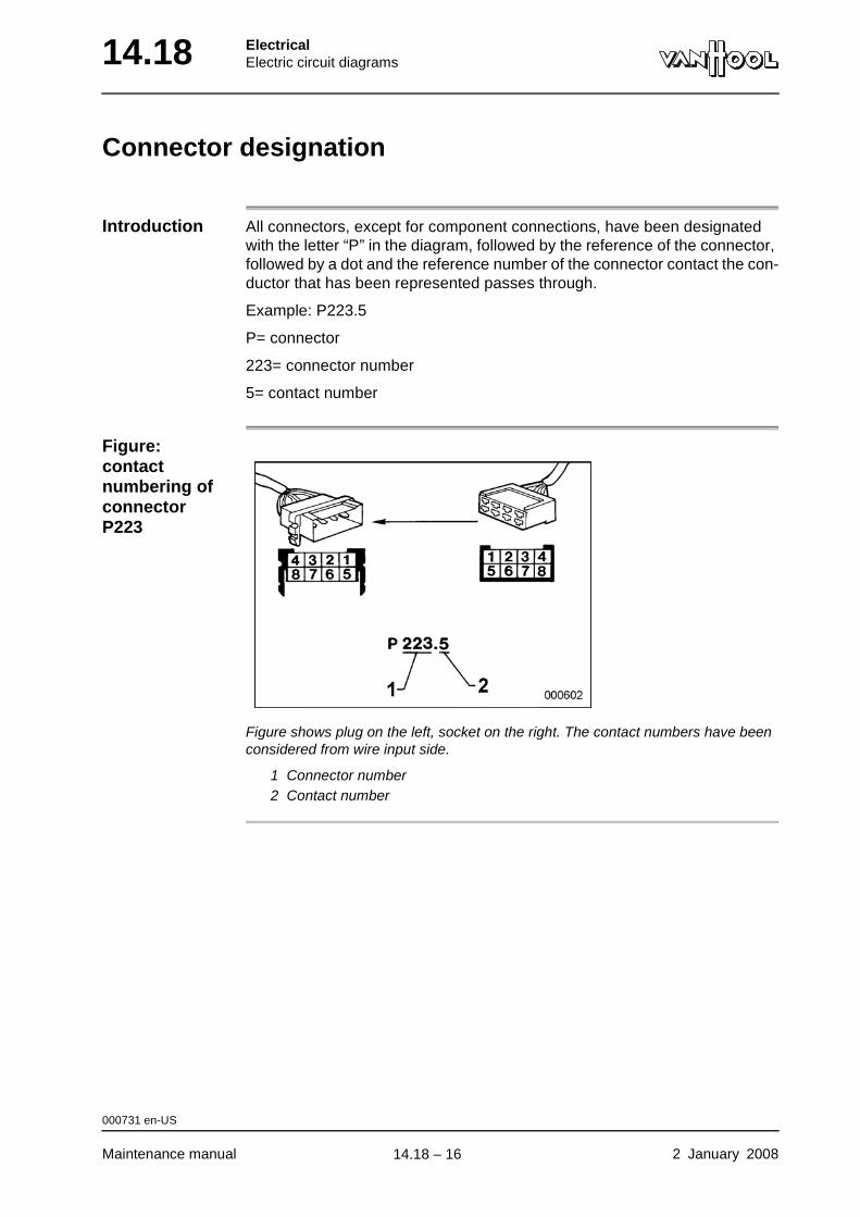
14.18 ElectricalElectric circuit diagrams
Connector designation
Introduction All connectors, except for component connections, have been designated with the letter “P” in the diagram, followed by the reference of the connector, followed by a dot and the reference number of the connector contact the con-ductor that has been represented passes through.
Example: P223.5
P= connector
223= connector number
5= contact number
Figure: contact numbering of connector P223
Figure shows plug on the left, socket on the right. The contact numbers have been considered from wire input side.
1 Connector number2 Contact number
000731 en-US
Maintenance manual 2 January 2008
.
14.18 – 16
C o m m e r c i a l V e h i c l e S y s t e m s
S e r v i c e M a n u a l Pneumatic Disc Brake
SN6.../ SN7.../ SK7.../ ADB22X
Description/Function
Service kits
Service
Equipment
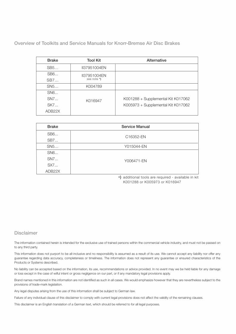
Disclaimer
The information contained herein is intended for the exclusive use of trained persons within the commercial vehicle industry, and must not be passed on
to any third party.
This information does not purport to be all-inclusive and no responsibility is assumed as a result of its use. We cannot accept any liability nor offer any
guarantee regarding data accuracy, completeness or timeliness. The information does not represent any guarantee or ensured characteristics of the
Products or Systems described.
No liability can be accepted based on the information, its use, recommendations or advice provided. In no event may we be held liable for any damage
or loss except in the case of wilful intent or gross negligence on our part, or if any mandatory legal provisions apply.
Brand names mentioned in this information are not identifi ed as such in all cases. We would emphasize however that they are nevertheless subject to the
provisions of trade-mark legislation.
Any legal disputes arising from the use of this information shall be subject to German law.
Failure of any individual clause of this disclaimer to comply with current legal provisions does not affect the validity of the remaining clauses.
This disclaimer is an English translation of a German text, which should be referred to for all legal purposes.
Brake Tool Kit Alternative
SB5… II37951004EN
SB6... II37951004EN
SB7... see note *)
SN5… K004789
SN6...
SN7... K016947
K001288 + Supplemental Kit K017062
SK7... K005973 + Supplemental Kit K017062
ADB22X
Brake Service Manual
SB6... C16352-EN
SB7...
SN5… Y015044-EN
SN6...
SN7... Y006471-EN
SX7...
ADB22X
*) additional tools are required - available in kit
K001288 or K005973 or K016947
Overview of Toolkits and Service Manuals for Knorr-Bremse Air Disc Brakes
3
Contents
1. Overview . . . . . . . . . . . . . . . . . . . . . . . . 6
1.1 Disc Brake Components . . . . . . . . . . . . . . . . . . 6
1.2 Brake Disc Identifi cation and Service Kits . . . . . . . . . . . . 7
1.2.1 Wear Indicator Kits . . . . . . . . . . . . . . . . . . . . 7
1.3 Brake Disc . . . . . . . . . . . . . . . . . . . . . . 8
2. General Information . . . . . . . . . . . . . . . . . . . . . . 9
2.1 Service Tools . . . . . . . . . . . . . . . . . . . . . 9
2.2 Diagnostic Equipment . . . . . . . . . . . . . . . . . . 9
2.3 Lubricant . . . . . . . . . . . . . . . . . . . . . . 9
2.4 Torque Requirements . . . . . . . . . . . . . . . . . . 9
3. Description and Function . . . . . . . . . . . . . . . . . . . . 10
3.1 Disc Brake Sectioned View . . . . . . . . . . . . . . . . . 10 3.2 Description of Operation . . . . . . . . . . . . . . . . . . 11
3.2.1 Brake Actuation . . . . . . . . . . . . . . . . . . . . 11
3.2.2 Brake Release . . . . . . . . . . . . . . . . . . . . . 11
3.2.3 Brake Adjustment . . . . . . . . . . . . . . . . . . . . 11
4. Inspection Points . . . . . . . . . . . . . . . . . . . . . . 12
4.1 Safety Instructions for Service Work and Repair Work . . . . . . . . 13
5. Functional and Visual Check . . . . . . . . . . . . . . . . . . . 14
5.1 Wear Check of Pads and Discs . . . . . . . . . . . . . . . 14
5.1.1 Brake Wear Check using Rubber Bush (6a) . . . . . . . . . . . . 16
5.1.2 Brake Wear Check using Rubber Bush (6b) . . . . . . . . . . . . 17
5.1.3 Brake Wear Check using Carrier to Caliper position (6c) . . . . . . . . 18
5.1.4 Wear Indicators . . . . . . . . . . . . . . . . . . . . . 19
5.1.5 Diagnostic Equipment ZB9031-2 . . . . . . . . . . . . . . . 19
5.2 Adjuster Check . . . . . . . . . . . . . . . . . . . . 20
5.3 Caliper Checks . . . . . . . . . . . . . . . . . . . . . 22
5.3.1 Caliper Running Clearence . . . . . . . . . . . . . . . . . 22
5.3.2 Caliper Movement along Guide Pins . . . . . . . . . . . . . . 22
5.3.3 Rubber Bush (6a, 6b) or Guide Sleeve (6c) to Guide Pin Clearance . . . . . . 22
5.4 Checking of Seals . . . . . . . . . . . . . . . . . . . . 23
5.4.1 Caliper Guide Pin Seals . . . . . . . . . . . . . . . . . . 23
5.4.2 Checking of Tappet and Boot Assemblies(13) . . . . . . . . . . . 24
6. Pad Replacement . . . . . . . . . . . . . . . . . . . . . . 25
6.1 Pad Removal . . . . . . . . . . . . . . . . . . . . . 25
6.2 Pad Fitting . . . . . . . . . . . . . . . . . . . . . . 26
6.3 Wear Indicator Fitting (Normally Closed or Normally Open Type) . . . . . . . . . . . . . . . . . . . 27
4
Contents
6.3.1 Cable Guide (105) . . . . . . . . . . . . . . . . . . . . 28
6.3.2 Cable Guide (105a) . . . . . . . . . . . . . . . . . . . 29
6.3.3 Protection Plate (104) . . . . . . . . . . . . . . . . . . . 29
7. Replacement of Tappet and Boot Assemblies (13) and Inner Seals (22) . . . . . 30
7.1 Tapped and Boot Assemblies (13) - Removal . . . . . . . . . . . 30
7.1.1 Treaded Tubes (16) - Inspection . . . . . . . . . . . . . . . . 31
7.2 Inner Seals (22) - Replacement . . . . . . . . . . . . . . . . 31
7.3 Tappet and Boot Assemblies (13) - Fitting . . . . . . . . . . . . 32
8. Caliper Replacement . . . . . . . . . . . . . . . . . . . . . 34
8.1 Caliper Removal . . . . . . . . . . . . . . . . . . . . 34
8.1.1 Removal of the Cover (10) . . . . . . . . . . . . . . . . . 34
8.1.2 Removal of the Cover (68c) . . . . . . . . . . . . . . . . . 34
8.1.3 Removal of the Cap (68a) . . . . . . . . . . . . . . . . . . 35
8.1.4 Remove Caliper from Carrier . . . . . . . . . . . . . . . . 35
8.2 Caliper Fitting (Carrier is fi tted on the axle) . . . . . . . . . . . . . . . . . . . . . . . 35
8.2.1 Fitting of Cover (10) and (68c) . . . . . . . . . . . . . . . . 36
8.2.2 Fitting of Cap (68a) . . . . . . . . . . . . . . . . . . . . 37
9. Replacement of Inner Boot (9) . . . . . . . . . . . . . . . . . . 38
10. Replacement of Guide Pin Bushes . . . . . . . . . . . . . . . . . 40
10.1 Brass Bush (7) - Replacement . . . . . . . . . . . . . . . . 40
10.1.1 Removal of Brass Bush (7) . . . . . . . . . . . . . . . . . 40
10.1.2 Fitting of Brass Bush (7) . . . . . . . . . . . . . . . . . . 40
10.2 Rubber Bush (6a or 6b) and Guide Sleeve (6c) . . . . . . . . . . . 41
10.2.1 Removal of Rubber Bush (6a or 6b) . . . . . . . . . . . . . . 41
10.2.2 Removal of Guide Sleeve (6c) . . . . . . . . . . . . . . . . 42
10.2.3 Fitting of Rubber Bush (6a or 6b) . . . . . . . . . . . . . . . 42
10.2.4 Fitting of Guide Sleeve (6c) . . . . . . . . . . . . . . . . . 43
11. Carrier Replacement . . . . . . . . . . . . . . . . . . . . . 45
12. Brake Actuator Replacement . . . . . . . . . . . . . . . . . . . 46
12.1 Brake Chamber Removal . . . . . . . . . . . . . . . . . 46
12.2 Brake Chamber Fitting . . . . . . . . . . . . . . . . . . 46
12.3 Spring Brake Removal . . . . . . . . . . . . . . . . . . 47
12.4 Spring Brake Fitting . . . . . . . . . . . . . . . . . . . 47
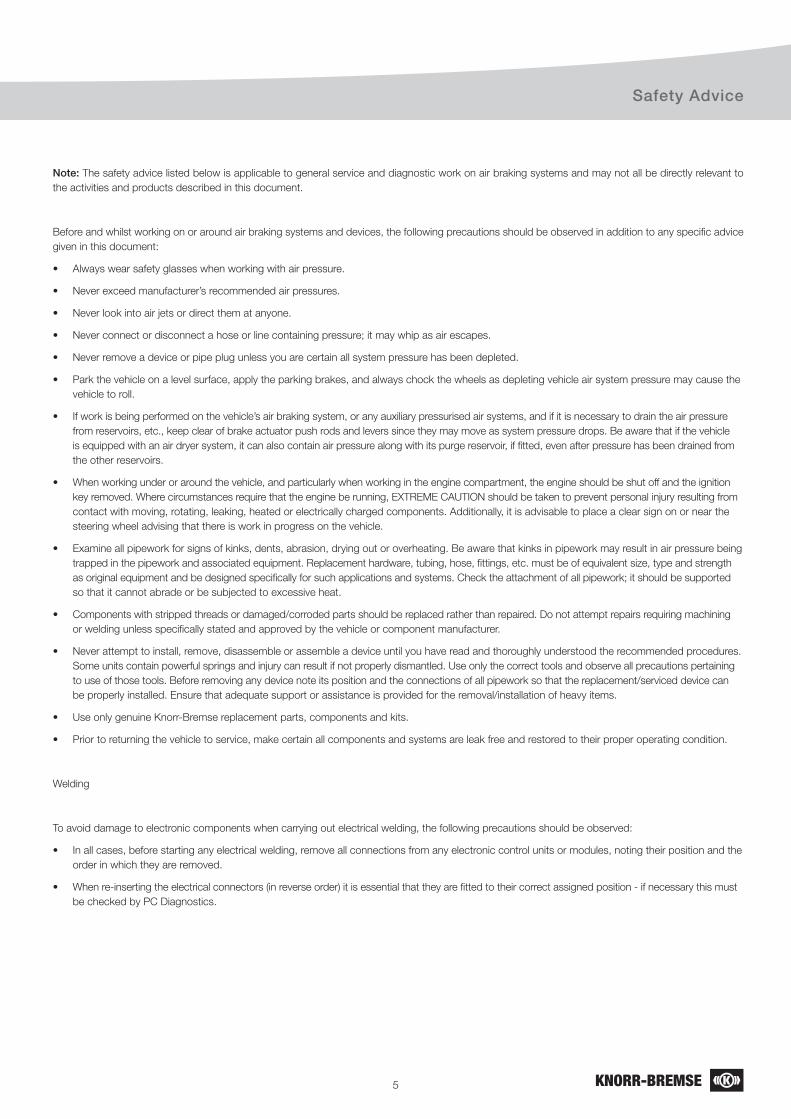
5
Safety Advice
Note: The safety advice listed below is applicable to general service and diagnostic work on air braking systems and may not all be directly relevant to
the activities and products described in this document.
Before and whilst working on or around air braking systems and devices, the following precautions should be observed in addition to any specifi c advice
given in this document:
• Always wear safety glasses when working with air pressure.
• Never exceed manufacturer’s recommended air pressures.
• Never look into air jets or direct them at anyone.
• Never connect or disconnect a hose or line containing pressure; it may whip as air escapes.
• Never remove a device or pipe plug unless you are certain all system pressure has been depleted.
• Park the vehicle on a level surface, apply the parking brakes, and always chock the wheels as depleting vehicle air system pressure may cause the
vehicle to roll.
• If work is being performed on the vehicle’s air braking system, or any auxiliary pressurised air systems, and if it is necessary to drain the air pressure
from reservoirs, etc., keep clear of brake actuator push rods and levers since they may move as system pressure drops. Be aware that if the vehicle
is equipped with an air dryer system, it can also contain air pressure along with its purge reservoir, if fi tted, even after pressure has been drained from
the other reservoirs.
• When working under or around the vehicle, and particularly when working in the engine compartment, the engine should be shut off and the ignition
key removed. Where circumstances require that the engine be running, EXTREME CAUTION should be taken to prevent personal injury resulting from
contact with moving, rotating, leaking, heated or electrically charged components. Additionally, it is advisable to place a clear sign on or near the
steering wheel advising that there is work in progress on the vehicle.
• Examine all pipework for signs of kinks, dents, abrasion, drying out or overheating. Be aware that kinks in pipework may result in air pressure being
trapped in the pipework and associated equipment. Replacement hardware, tubing, hose, fi ttings, etc. must be of equivalent size, type and strength
as original equipment and be designed specifi cally for such applications and systems. Check the attachment of all pipework; it should be supported
so that it cannot abrade or be subjected to excessive heat.
• Components with stripped threads or damaged/corroded parts should be replaced rather than repaired. Do not attempt repairs requiring machining
or welding unless specifi cally stated and approved by the vehicle or component manufacturer.
• Never attempt to install, remove, disassemble or assemble a device until you have read and thoroughly understood the recommended procedures.
Some units contain powerful springs and injury can result if not properly dismantled. Use only the correct tools and observe all precautions pertaining
to use of those tools. Before removing any device note its position and the connections of all pipework so that the replacement/serviced device can
be properly installed. Ensure that adequate support or assistance is provided for the removal/installation of heavy items.
• Use only genuine Knorr-Bremse replacement parts, components and kits.
• Prior to returning the vehicle to service, make certain all components and systems are leak free and restored to their proper operating condition.
Welding
To avoid damage to electronic components when carrying out electrical welding, the following precautions should be observed:
• In all cases, before starting any electrical welding, remove all connections from any electronic control units or modules, noting their position and the
order in which they are removed.
• When re-inserting the electrical connectors (in reverse order) it is essential that they are fi tted to their correct assigned position - if necessary this must
be checked by PC Diagnostics.
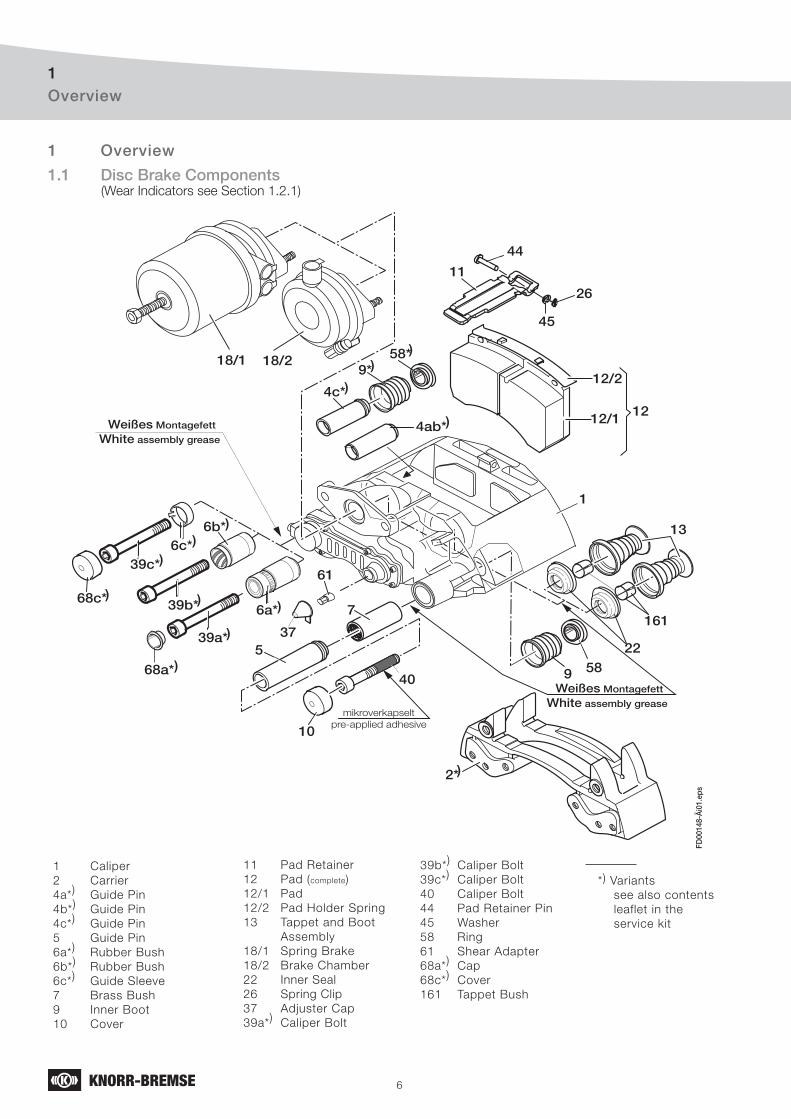
6
Overview1
1.1 Disc Brake Components (Wear Indicators see Section 1.2.1)
26
44
11
5
7
9 58
37
45
1
13
161
18/1 18/2
12
61
39a*
6a*)39b*
6b*)
10
2*
12/2
12/1
mikroverkapselt
pre-applied adhesive
40
Weißes Montagefett
White assembly grease
Weißes Montagefett
White assembly grease
22
4c*
9*58*
4ab*
68c*
39c*
FD00
148-
Äi0
1.ep
s
)
)
)
)
)
)
6c*)
))
)
68a*)
1 Caliper
2 Carrier
4a*) Guide Pin
4b*) Guide Pin
4c*) Guide Pin
5 Guide Pin
6a*) Rubber Bush
6b*) Rubber Bush
6c*) Guide Sleeve
7 Brass Bush
9 Inner Boot
10 Cover
11 Pad Retainer
12 Pad (complete)
12/1 Pad
12/2 Pad Holder Spring
13 Tappet and Boot
Assembly
18/1 Spring Brake
18/2 Brake Chamber
22 Inner Seal
26 Spring Clip
37 Adjuster Cap
39a*)
Caliper Bolt
39b*)
Caliper Bolt
39c*)
Caliper Bolt
40 Caliper Bolt
44 Pad Retainer Pin
45 Washer
58 Ring
61 Shear Adapter
68a*)
Cap
68c*)
Cover
161 Tappet Bush
*) Variants
see also contents
leaflet in the
service kit
1 Overview

7
Overview1
1.2 Brake Disc Identifi cation and Service Kits
Type of Caliper
KNORR-BREMSE Part no.
Axle- or Vehicle Manufacturer’s no.
Date of ManufactureUse only genuine Knorr-Bremse parts!
The following Service Kits are available :
Description Contents
Carrier 2
Guide Pins and Seals Kit 4a*), 5, 6a*), 7, 9, 10, 39a*), 40, 58
(4b*), 4c*), 6b*), 6c*), 39b*), 68a*), 68c*)
Tappet and Boot Kit (2 pieces) 13 (2x), 22 (2x), 161 (2x)
Adjuster Cap 37 (10 pcs), 61 (10 pcs)
Pad Kit (per axle) 11, 12, 26, 37, 44, 45, 61
Wear Indicator Kit (per axle) Variants see Section. 1.2.1
Air Disc Brake without Carrier (2)
Caliper and without Brake Pads (12).
Guide Pins Seals Kit provided for assembly
of Caliper to existing Brake Carrier.
For specific Service Part
Numbers for each Disc Brake
see:
www.Knorr-BremseSFN.com
www.Knorr-BremseSFN.biz
Knorr-Bremse offers a range of specifically designed rationalised Calipers to service a wide range of Disc Brakes.
For specific Caliper Part Number, see:
Brochure P-3543 or www.Knorr-BremseSFN.comwww.Knorr-BremseSFN.biz
*) Variants1.2.1 Wear Indicator Kits (typical kits are shown below)
Type 1
Type 3
Type 2
FD
00306.e
ps
105a
Alternative to Item 10511 Pad Retainer
101 Sensor
103 Cable to electrical Supply
104 Cable Protection Plate
105 Cable Guide
105a Cable Guide
8
1.3 Brake Disc
When replacing Discs, please refer to the instructions of the Vehicle Manufacturer,
including when fi tting Knorr-Bremse Brake Discs.
When replacing Discs, please adhere to the recommended bolt tightening torques.
The use of non-approved Brake Discs will reduce levels of safety and invalidate warranty.
Brake Discs can be ordered through the Knorr-Bremse Aftermarket Organisation.
Brake Disc1
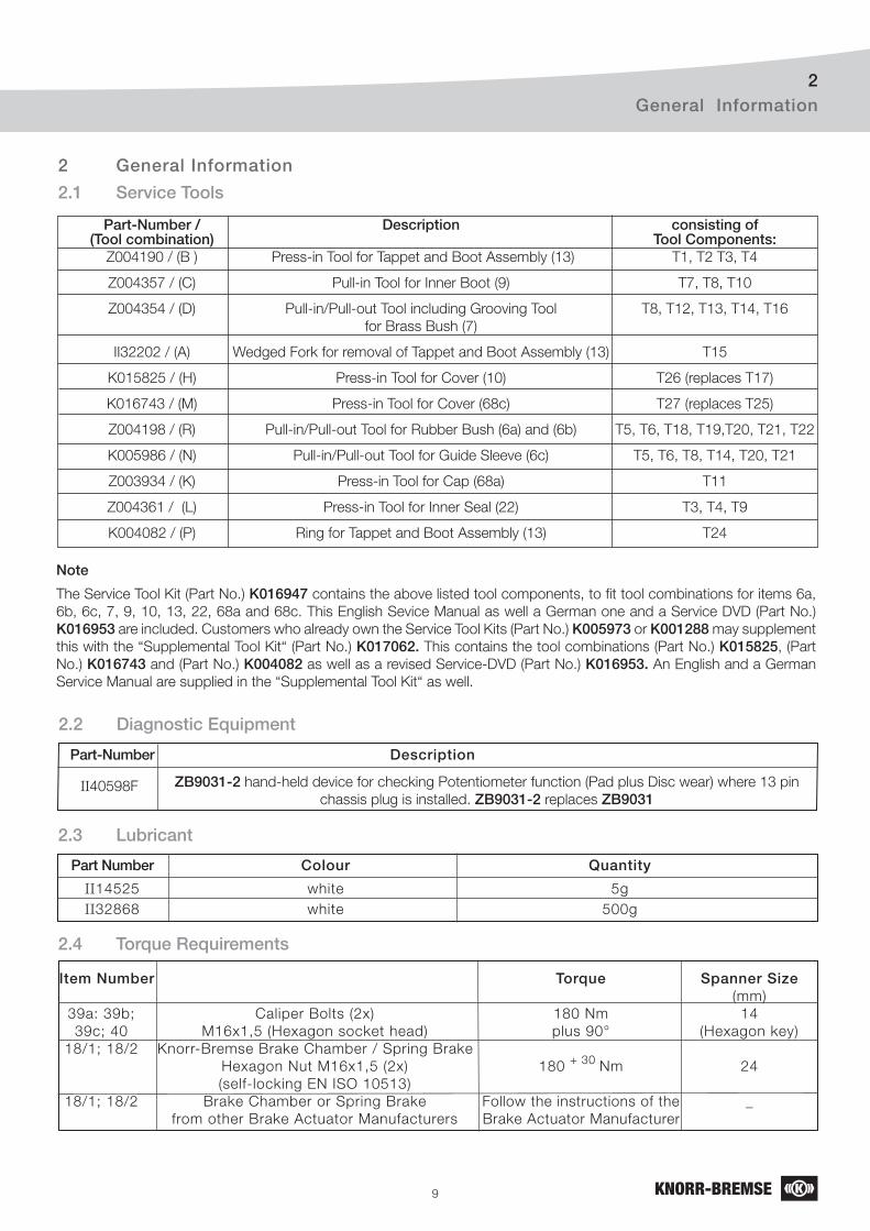
9
General Information2
Note
The Service Tool Kit (Part No.) K016947 contains the above listed tool components, to fi t tool combinations for items 6a,
6b, 6c, 7, 9, 10, 13, 22, 68a and 68c. This English Sevice Manual as well a German one and a Service DVD (Part No.)
K016953 are included. Customers who already own the Service Tool Kits (Part No.) K005973 or K001288 may supplement
this with the “Supplemental Tool Kit“ (Part No.) K017062. This contains the tool combinations (Part No.) K015825, (Part
No.) K016743 and (Part No.) K004082 as well as a revised Service-DVD (Part No.) K016953. An English and a German
Service Manual are supplied in the “Supplemental Tool Kit“ as well.
Part-Number Description
ZB9031-2 hand-held device for checking Potentiometer function (Pad plus Disc wear) where 13 pin
chassis plug is installed. ZB9031-2 replaces ZB9031
2.2 Diagnostic Equipment
II40598F
2.1 Service Tools
Part-Number / Description consisting of (Tool combination) Tool Components: Z004190 / (B ) Press-in Tool for Tappet and Boot Assembly (13) T1, T2 T3, T4
Z004357 / (C) Pull-in Tool for Inner Boot (9) T7, T8, T10
Z004354 / (D) Pull-in/Pull-out Tool including Grooving Tool T8, T12, T13, T14, T16
for Brass Bush (7)
II32202 / (A) Wedged Fork for removal of Tappet and Boot Assembly (13) T15
K015825 / (H) Press-in Tool for Cover (10) T26 (replaces T17)
K016743 / (M) Press-in Tool for Cover (68c) T27 (replaces T25)
Z004198 / (R) Pull-in/Pull-out Tool for Rubber Bush (6a) and (6b) T5, T6, T18, T19,T20, T21, T22
K005986 / (N) Pull-in/Pull-out Tool for Guide Sleeve (6c) T5, T6, T8, T14, T20, T21
Z003934 / (K) Press-in Tool for Cap (68a) T11
Z004361 / (L) Press-in Tool for Inner Seal (22) T3, T4, T9
K004082 / (P) Ring for Tappet and Boot Assembly (13) T24
Part Number Colour Quantity
II14525 white 5g
II32868 white 500g
2.3 Lubricant
2 General Information
Item Number Torque Spanner Size (mm)
39a: 39b; Caliper Bolts (2x) 180 Nm 14
39c; 40 M16x1,5 (Hexagon socket head) plus 90° (Hexagon key)
18/1; 18/2 Knorr-Bremse Brake Chamber / Spring Brake
Hexagon Nut M16x1,5 (2x) 180 + 30
Nm 24
(self-locking EN ISO 10513)
18/1; 18/2 Brake Chamber or Spring Brake Follow the instructions of the _
from other Brake Actuator Manufacturers Brake Actuator Manufacturer
2.4 Torque Requirements
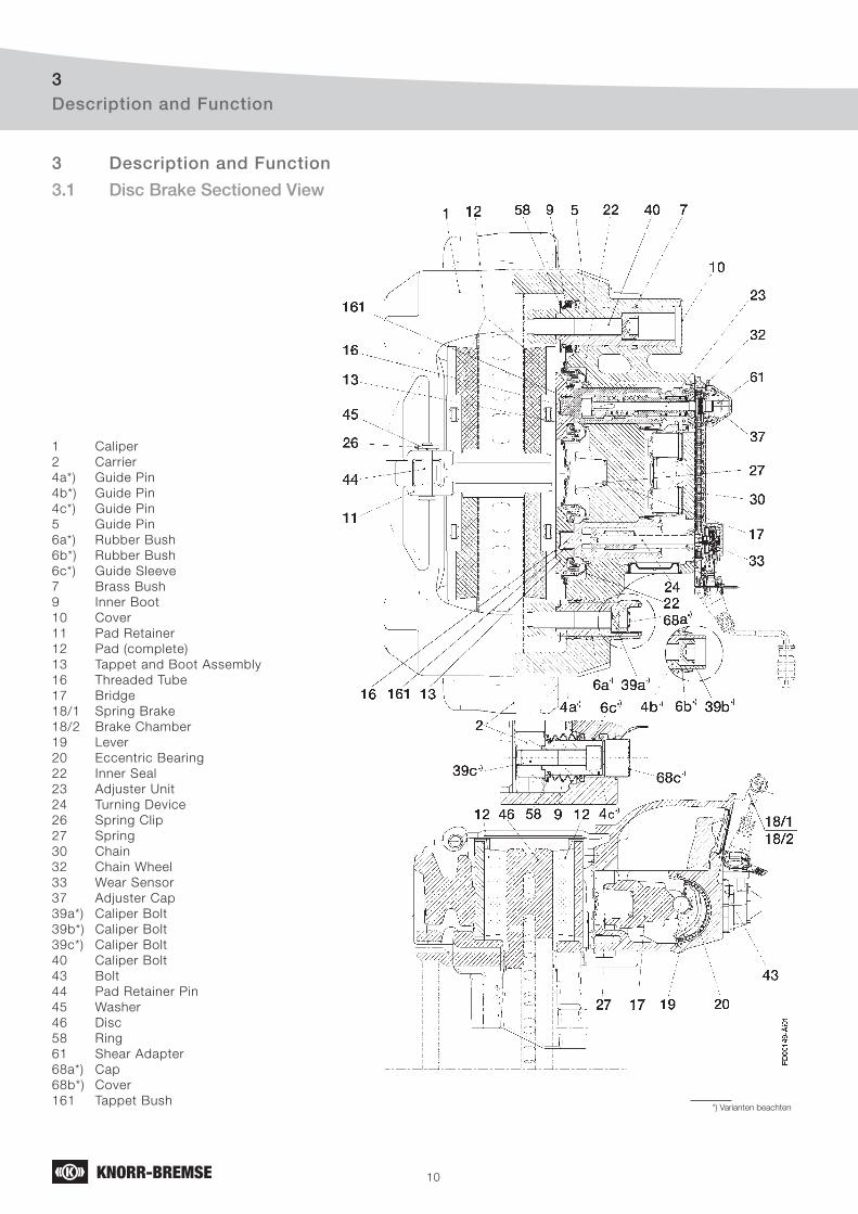
10
Description and Function3
3.1 Disc Brake Sectioned View
1 Caliper
2 Carrier
4a*) Guide Pin
4b*) Guide Pin
4c*) Guide Pin
5 Guide Pin
6a*) Rubber Bush
6b*) Rubber Bush
6c*) Guide Sleeve
7 Brass Bush
9 Inner Boot
10 Cover
11 Pad Retainer
12 Pad (complete)
13 Tappet and Boot Assembly
16 Threaded Tube
17 Bridge
18/1 Spring Brake
18/2 Brake Chamber
19 Lever
20 Eccentric Bearing
22 Inner Seal
23 Adjuster Unit
24 Turning Device
26 Spring Clip
27 Spring
30 Chain
32 Chain Wheel
33 Wear Sensor
37 Adjuster Cap
39a*) Caliper Bolt
39b*) Caliper Bolt
39c*) Caliper Bolt
40 Caliper Bolt
43 Bolt
44 Pad Retainer Pin
45 Washer
46 Disc
58 Ring
61 Shear Adapter
68a*) Cap
68b*) Cover
161 Tappet Bush*) Varianten beachten
3 Description and Function
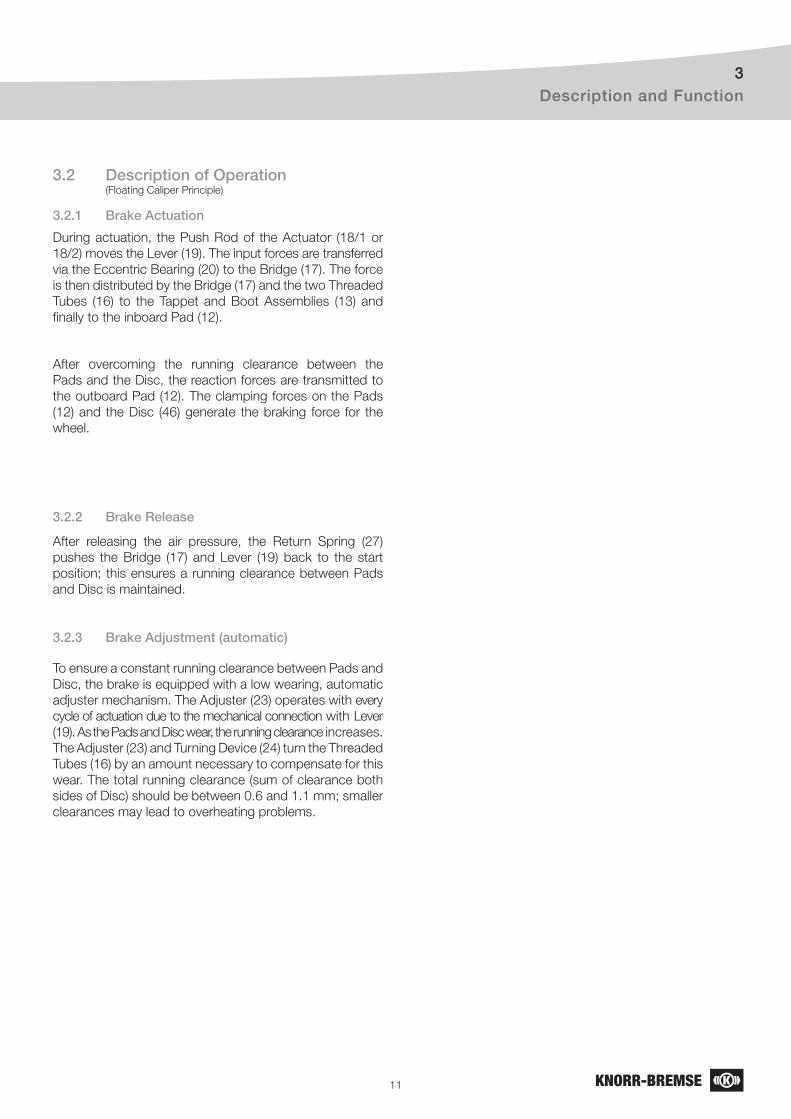
11
Description and Function3
3.2 Description of Operation (Floating Caliper Principle)
During actuation, the Push Rod of the Actuator (18/1 or
18/2) moves the Lever (19). The input forces are transferred
via the Eccentric Bearing (20) to the Bridge (17). The force
is then distributed by the Bridge (17) and the two Threaded
Tubes (16) to the Tappet and Boot Assemblies (13) and
fi nally to the inboard Pad (12).
After overcoming the running clearance between the
Pads and the Disc, the reaction forces are transmitted to
the outboard Pad (12). The clamping forces on the Pads
(12) and the Disc (46) generate the braking force for the
wheel.
3.2.1 Brake Actuation
3.2.2 Brake Release
After releasing the air pressure, the Return Spring (27)
pushes the Bridge (17) and Lever (19) back to the start
position; this ensures a running clearance between Pads
and Disc is maintained.
3.2.3 Brake Adjustment (automatic)
To ensure a constant running clearance between Pads and
Disc, the brake is equipped with a low wearing, automatic
adjuster mechanism. The Adjuster (23) operates with every
cycle of actuation due to the mechanical connection with Lever
(19). As the Pads and Disc wear, the running clearance increases.
The Adjuster (23) and Turning Device (24) turn the Threaded
Tubes (16) by an amount necessary to compensate for this
wear. The total running clearance (sum of clearance both
sides of Disc) should be between 0.6 and 1.1 mm; smaller
clearances may lead to overheating problems.
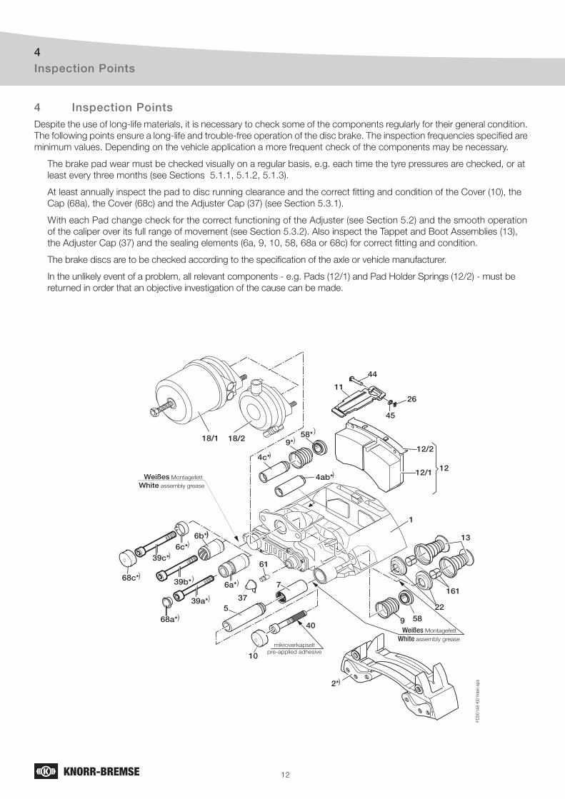
12
Inspection Points4
Despite the use of long-life materials, it is necessary to check some of the components regularly for their general condition.
The following points ensure a long-life and trouble-free operation of the disc brake. The inspection frequencies specifi ed are
minimum values. Depending on the vehicle application a more frequent check of the components may be necessary.
The brake pad wear must be checked visually on a regular basis, e.g. each time the tyre pressures are checked, or at
least every three months (see Sections 5.1.1, 5.1.2, 5.1.3).
At least annually inspect the pad to disc running clearance and the correct fi tting and condition of the Cover (10), the
Cap (68a), the Cover (68c) and the Adjuster Cap (37) (see Section 5.3.1).
With each Pad change check for the correct functioning of the Adjuster (see Section 5.2) and the smooth operation
of the caliper over its full range of movement (see Section 5.3.2). Also inspect the Tappet and Boot Assemblies (13),
the Adjuster Cap (37) and the sealing elements (6a, 9, 10, 58, 68a or 68c) for correct fi tting and condition.
The brake discs are to be checked according to the specifi cation of the axle or vehicle manufacturer.
In the unlikely event of a problem, all relevant components - e.g. Pads (12/1) and Pad Holder Springs (12/2) - must be
returned in order that an objective investigation of the cause can be made.
4 Inspection Points
26
44
11
5
7
9 58
37
45
1
13
161
18/1 18/2
12
61
39a*
6a*)39b*
6b*)
68a*)
10
2*
12/2
12/1
mikroverkapselt
pre-applied adhesive
40
Weißes Montagefett
White assembly grease
Weißes Montagefett
White assembly grease
22
4c*
9*58*
4ab*
68c*
39c*
FD
00148-€
i01kle
in.e
ps
)
)
)
)
)
)
6c*)
)
)
)
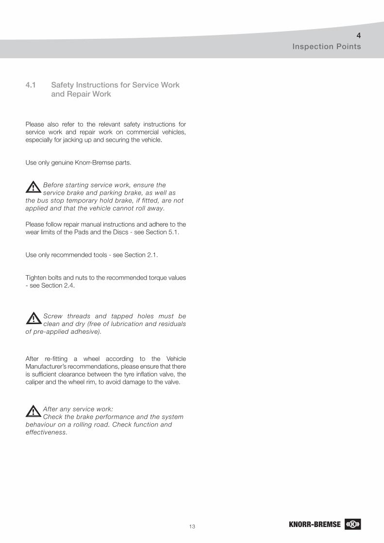
13
Inspection Points4
4.1 Safety Instructions for Service Work and Repair Work
Please also refer to the relevant safety instructions for
service work and repair work on commercial vehicles,
especially for jacking up and securing the vehicle.
Use only genuine Knorr-Bremse parts.
Before starting service work, ensure the
service brake and parking brake, as well as
the bus stop temporary hold brake, if fitted, are not
applied and that the vehicle cannot roll away.
Please follow repair manual instructions and adhere to the
wear limits of the Pads and the Discs - see Section 5.1.
Use only recommended tools - see Section 2.1.
Tighten bolts and nuts to the recommended torque values
- see Section 2.4.
Screw threads and tapped holes must be
clean and dry (free of lubrication and residuals
of pre-applied adhesive).
After re-fi tting a wheel according to the Vehicle
Manufacturer’s recommendations, please ensure that there
is suffi cient clearance between the tyre infl ation valve, the
caliper and the wheel rim, to avoid damage to the valve.
After any service work:
Check the brake performance and the system
behaviour on a rolling road. Check function and
effectiveness.
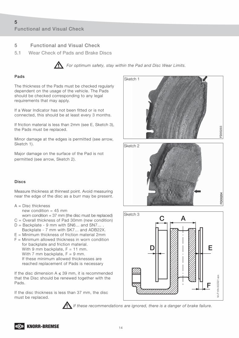
14
Functional and Visual Check5
5.1 Wear Check of Pads and Brake Discs
For optimum safety, stay within the Pad and Disc Wear Limits.
ED
C A
F
M+
P-K
N-0
02
Äi0
1.e
ps
Sketch 1
Sketch 2
Sketch 3
Pads
The thickness of the Pads must be checked regularly
dependent on the usage of the vehicle. The Pads
should be checked corresponding to any legal
requirements that may apply.
If a Wear Indicator has not been fitted or is not
connected, this should be at least every 3 months.
If friction material is less than 2mm (see E, Sketch 3),
the Pads must be replaced.
Minor damage at the edges is permitted (see arrow,
Sketch 1).
Major damage on the surface of the Pad is not
permitted (see arrow, Sketch 2).
Discs
Measure thickness at thinnest point. Avoid measuring
near the edge of the disc as a burr may be present.
A = Disc thickness
new condition = 45 mm
worn condition = 37 mm (the disc must be replaced)
C = Overall thickness of Pad 30mm (new condition)
D = Backplate - 9 mm with SN6... and SN7... .
Backplate - 7 mm with SK7... and ADB22X.
E = Minimum thickness of friction material 2mm
F = Minimum allowed thickness in worn condition
for backplate and friction material.
With 9 mm backplate, F = 11 mm.
With 7 mm backplate, F = 9 mm.
If these minimum allowed thicknesses are
reached replacement of Pads is necessary
If the disc dimension A ≤ 39 mm, it is recommended
that the Disc should be renewed together with the
Pads.
If the disc thickness is less than 37 mm, the disc
must be replaced.
If these recommendations are ignored, there is a danger of brake failure.
5 Functional and Visual Check
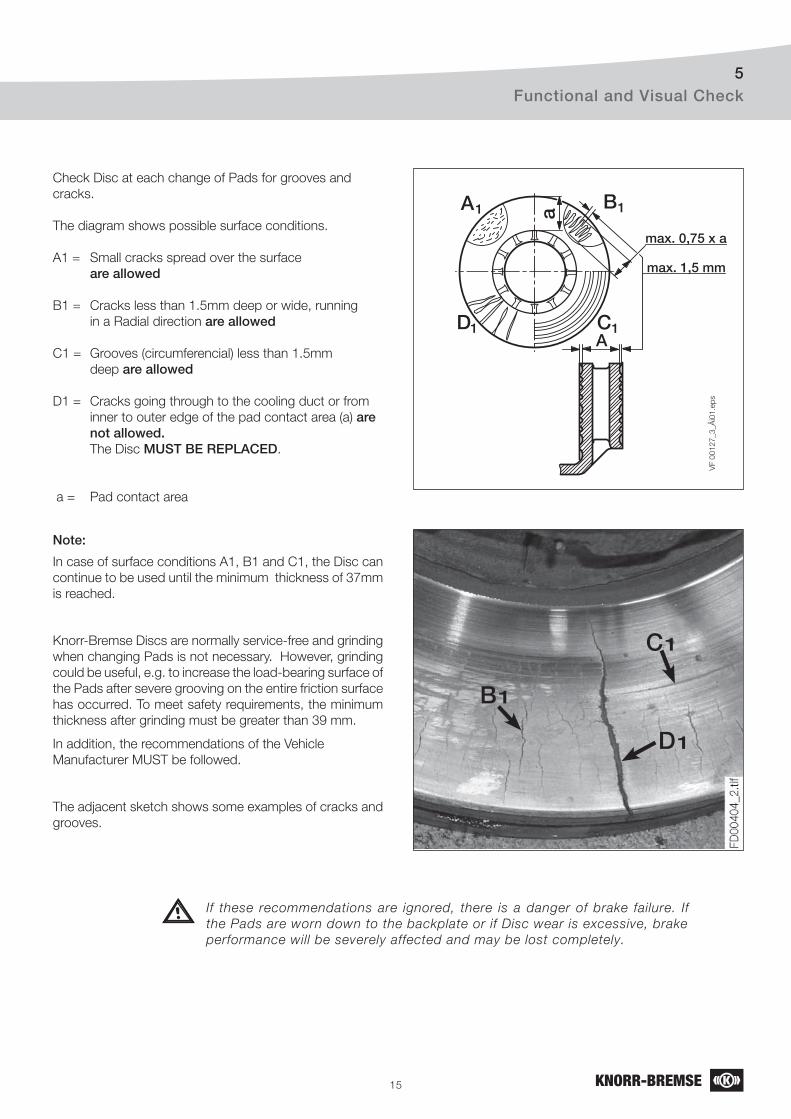
15
Check Disc at each change of Pads for grooves and
cracks.
The diagram shows possible surface conditions.
A1 = Small cracks spread over the surface
are allowed
B1 = Cracks less than 1.5mm deep or wide, running
in a Radial direction are allowed
C1 = Grooves (circumferencial) less than 1.5mm
deep are allowed
D1 = Cracks going through to the cooling duct or from
inner to outer edge of the pad contact area (a) are not allowed. The Disc MUST BE REPLACED.
a = Pad contact area
Note:
In case of surface conditions A1, B1 and C1, the Disc can
continue to be used until the minimum thickness of 37mm
is reached.
Knorr-Bremse Discs are normally service-free and grinding
when changing Pads is not necessary. However, grinding
could be useful, e.g. to increase the load-bearing surface of
the Pads after severe grooving on the entire friction surface
has occurred. To meet safety requirements, the minimum
thickness after grinding must be greater than 39 mm.
In addition, the recommendations of the Vehicle
Manufacturer MUST be followed.
The adjacent sketch shows some examples of cracks and
grooves.
VF 0
01
27
_3
_Ä
i01
.ep
s
max. 0,75 x a
a
A
A1 B1
D1 C1
max. 1,5 mm
C1
D1
B1
If these recommendations are ignored, there is a danger of brake failure. If
the Pads are worn down to the backplate or if Disc wear is excessive, brake
performance will be severely affected and may be lost completely.
Functional and Visual Check5
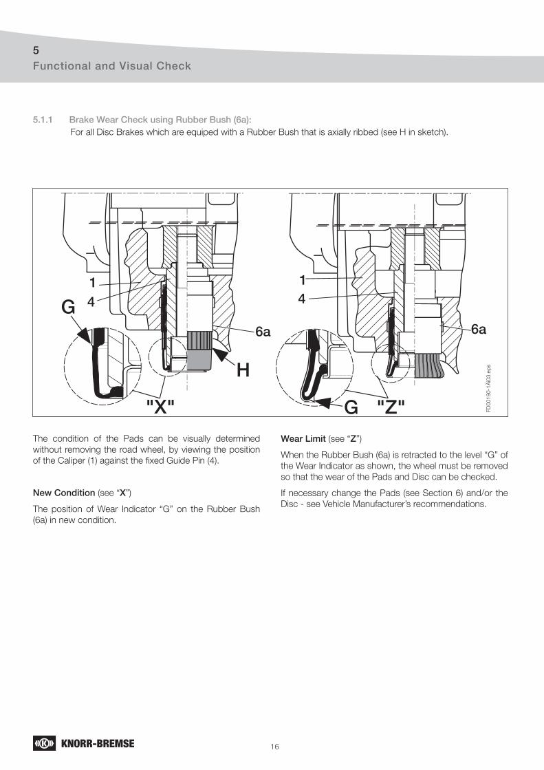
16
G
G"X" "Z"
6a 6a
FD
00190-1
Äi0
3.e
ps
44
H
1 1
Functional and Visual Check5
5.1.1 Brake Wear Check using Rubber Bush (6a):For all Disc Brakes which are equiped with a Rubber Bush that is axially ribbed (see H in sketch).
The condition of the Pads can be visually determined
without removing the road wheel, by viewing the position
of the Caliper (1) against the fi xed Guide Pin (4).
New Condition (see “X”)
The position of Wear Indicator “G” on the Rubber Bush
(6a) in new condition.
Wear Limit (see “Z”)
When the Rubber Bush (6a) is retracted to the level “G” of
the Wear Indicator as shown, the wheel must be removed
so that the wear of the Pads and Disc can be checked.
If necessary change the Pads (see Section 6) and/or the
Disc - see Vehicle Manufacturer’s recommendations.
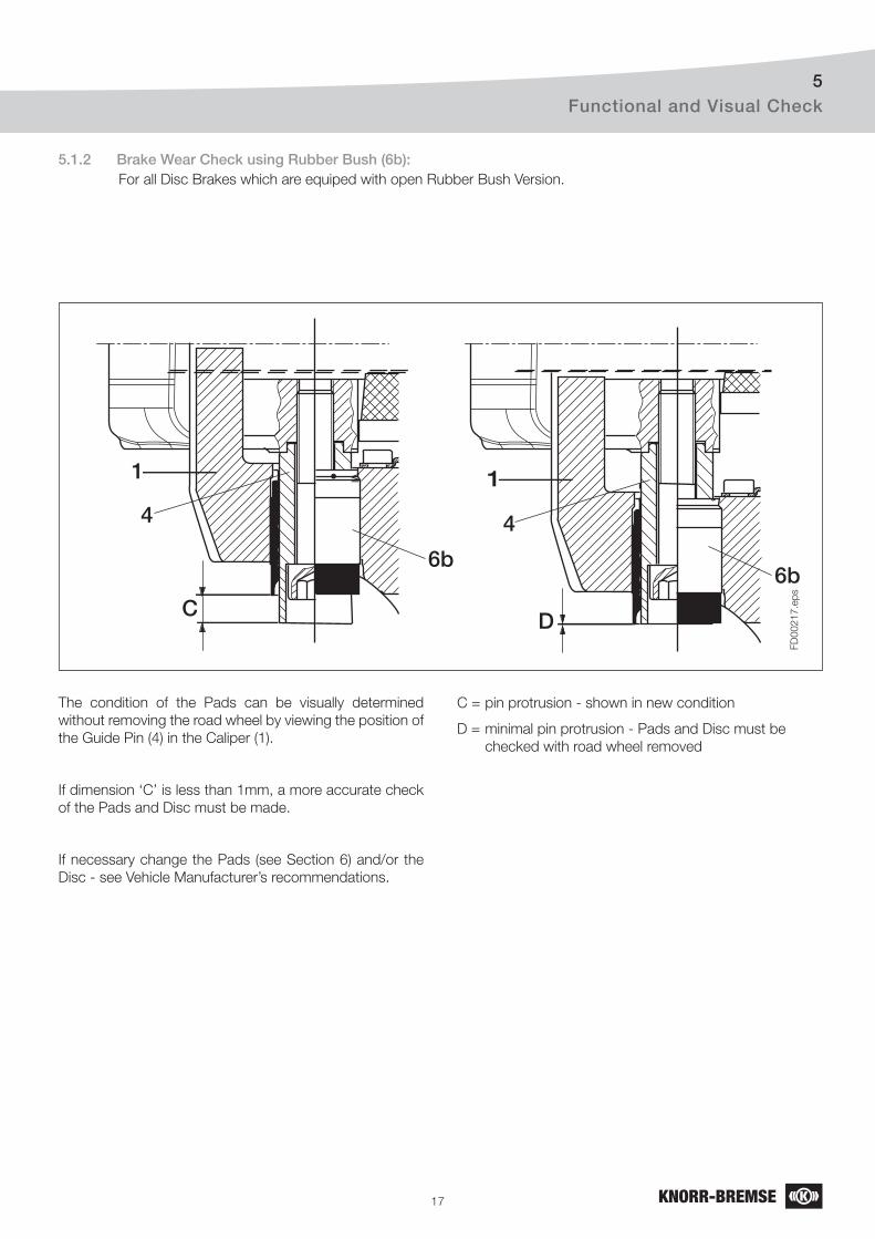
17
FD
00
21
7.e
ps
C D
6b
4
1
6b
4
1
5.1.2 Brake Wear Check using Rubber Bush (6b):For all Disc Brakes which are equiped with open Rubber Bush Version.
The condition of the Pads can be visually determined
without removing the road wheel by viewing the position of
the Guide Pin (4) in the Caliper (1).
If dimension ‘C’ is less than 1mm, a more accurate check
of the Pads and Disc must be made.
If necessary change the Pads (see Section 6) and/or the
Disc - see Vehicle Manufacturer’s recommendations.
C = pin protrusion - shown in new condition
D = minimal pin protrusion - Pads and Disc must be
checked with road wheel removed
≤•
Functional and Visual Check5
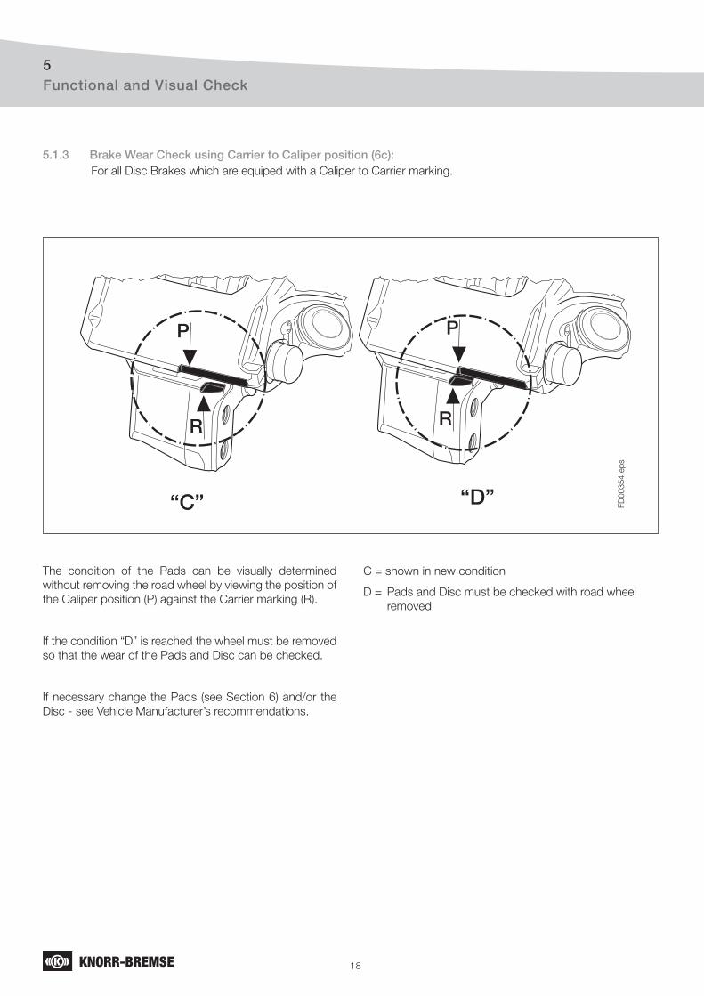
18
P
R
P
R
FD
00
35
4.e
ps
Functional and Visual Check5
5.1.3 Brake Wear Check using Carrier to Caliper position (6c):For all Disc Brakes which are equiped with a Caliper to Carrier marking.
The condition of the Pads can be visually determined
without removing the road wheel by viewing the position of
the Caliper position (P) against the Carrier marking (R).
If the condition “D” is reached the wheel must be removed
so that the wear of the Pads and Disc can be checked.
If necessary change the Pads (see Section 6) and/or the
Disc - see Vehicle Manufacturer’s recommendations.
C = shown in new condition
D = Pads and Disc must be checked with road wheel
removed
“C” “D”
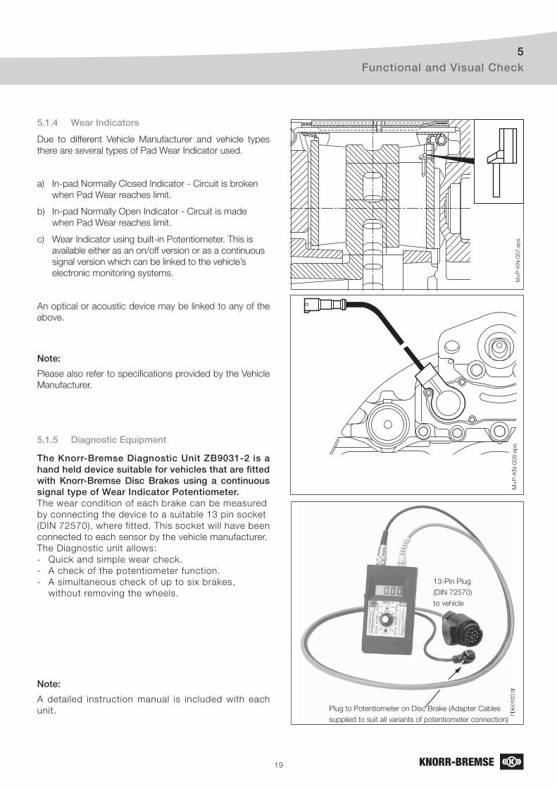
19
Functional and Visual Check5
M+
P-K
N-0
07.e
ps
M+
P-K
N-0
08
.ep
s
Plug to Potentiometer on Disc Brake (Adapter Cables
supplied to suit all variants of potentiometer connection)
13-Pin Plug
(DIN 72570)
to vehicle
5.1.4 Wear Indicators
Due to different Vehicle Manufacturer and vehicle types
there are several types of Pad Wear Indicator used.
a) In-pad Normally Closed Indicator - Circuit is broken
when Pad Wear reaches limit.
b) In-pad Normally Open Indicator - Circuit is made
when Pad Wear reaches limit.
c) Wear Indicator using built-in Potentiometer. This is
available either as an on/off version or as a continuous
signal version which can be linked to the vehicle’s
electronic monitoring systems.
An optical or acoustic device may be linked to any of the
above.
Note:
Please also refer to specifi cations provided by the Vehicle
Manufacturer.
5.1.5 Diagnostic Equipment
The Knorr-Bremse Diagnostic Unit ZB9031-2 is a hand held device suitable for vehicles that are fi tted with Knorr-Bremse Disc Brakes using a continuous signal type of Wear Indicator Potentiometer.The wear condition of each brake can be measured
by connecting the device to a suitable 13 pin socket
(DIN 72570), where fitted. This socket will have been
connected to each sensor by the vehicle manufacturer.
The Diagnostic unit allows:
- Quick and simple wear check.
- A check of the potentiometer function.
- A simultaneous check of up to six brakes,
without removing the wheels.
Note:
A detailed instruction manual is included with each
unit.
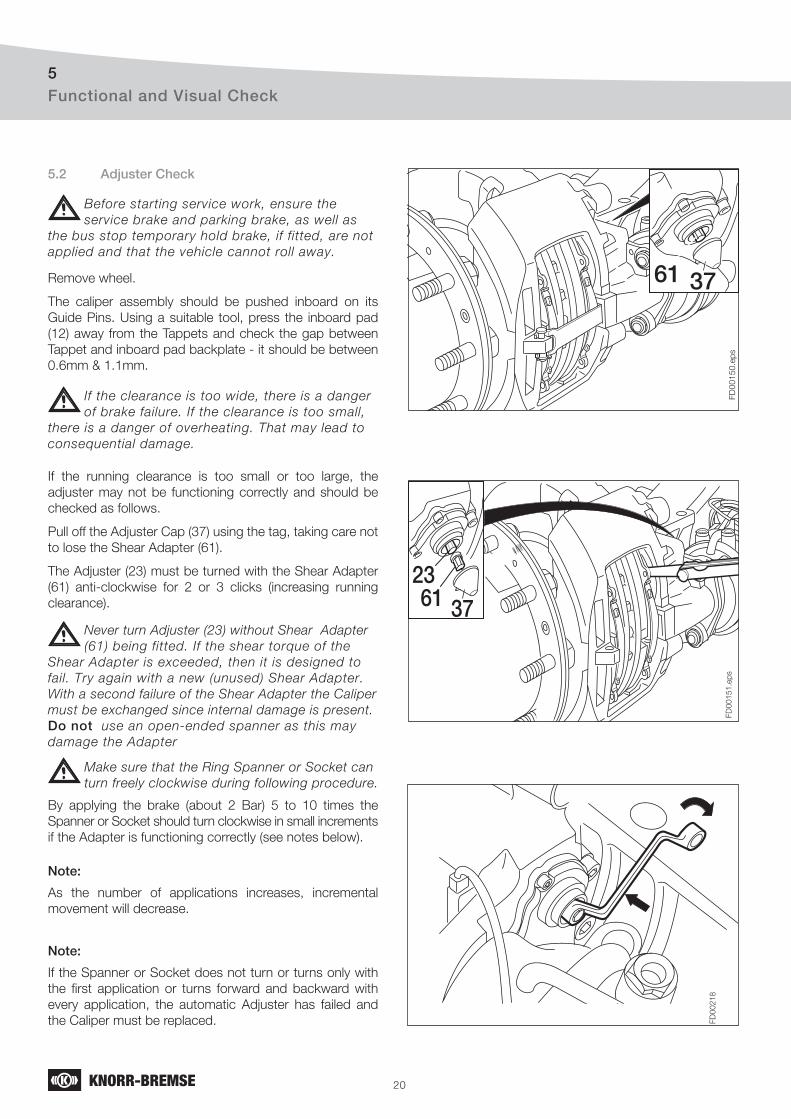
20
Functional and Visual Check5
FD
00150.e
ps
61 37
233761
FD
00151.e
ps
FD
00218
5.2 Adjuster Check
Remove wheel.
The caliper assembly should be pushed inboard on its
Guide Pins. Using a suitable tool, press the inboard pad
(12) away from the Tappets and check the gap between
Tappet and inboard pad backplate - it should be between
0.6mm & 1.1mm.
If the clearance is too wide, there is a danger
of brake failure. If the clearance is too small,
there is a danger of overheating. That may lead to
consequential damage.
If the running clearance is too small or too large, the
adjuster may not be functioning correctly and should be
checked as follows.
Pull off the Adjuster Cap (37) using the tag, taking care not
to lose the Shear Adapter (61).
The Adjuster (23) must be turned with the Shear Adapter
(61) anti-clockwise for 2 or 3 clicks (increasing running
clearance).
Never turn Adjuster (23) without Shear Adapter
(61) being fitted. If the shear torque of the
Shear Adapter is exceeded, then it is designed to
fail. Try again with a new (unused) Shear Adapter.
With a second failure of the Shear Adapter the Caliper
must be exchanged since internal damage is present.
Do not use an open-ended spanner as this may
damage the Adapter
Make sure that the Ring Spanner or Socket can
turn freely clockwise during following procedure.
By applying the brake (about 2 Bar) 5 to 10 times the
Spanner or Socket should turn clockwise in small increments
if the Adapter is functioning correctly (see notes below).
Note:
As the number of applications increases, incremental
movement will decrease.
Note:
If the Spanner or Socket does not turn or turns only with
the fi rst application or turns forward and backward with
every application, the automatic Adjuster has failed and
the Caliper must be replaced.
Before starting service work, ensure the
service brake and parking brake, as well as
the bus stop temporary hold brake, if fitted, are not
applied and that the vehicle cannot roll away.
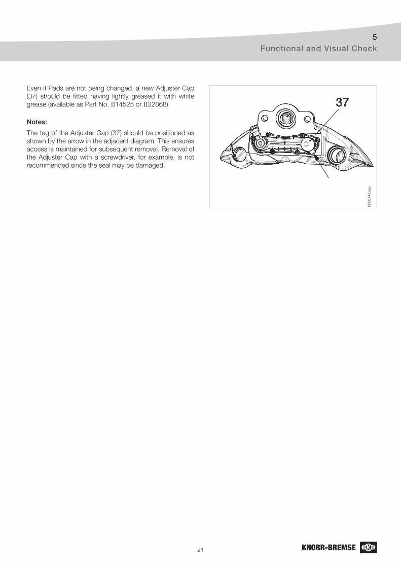
21
Functional and Visual Check5
FD
00144.e
ps
37Even if Pads are not being changed, a new Adjuster Cap
(37) should be fi tted having lightly greased it with white
grease (available as Part No. II14525 or II32868).
Notes:
The tag of the Adjuster Cap (37) should be positioned as
shown by the arrow in the adjacent diagram. This ensures
access is maintained for subsequent removal. Removal of
the Adjuster Cap with a screwdriver, for example, is not
recommended since the seal may be damaged.
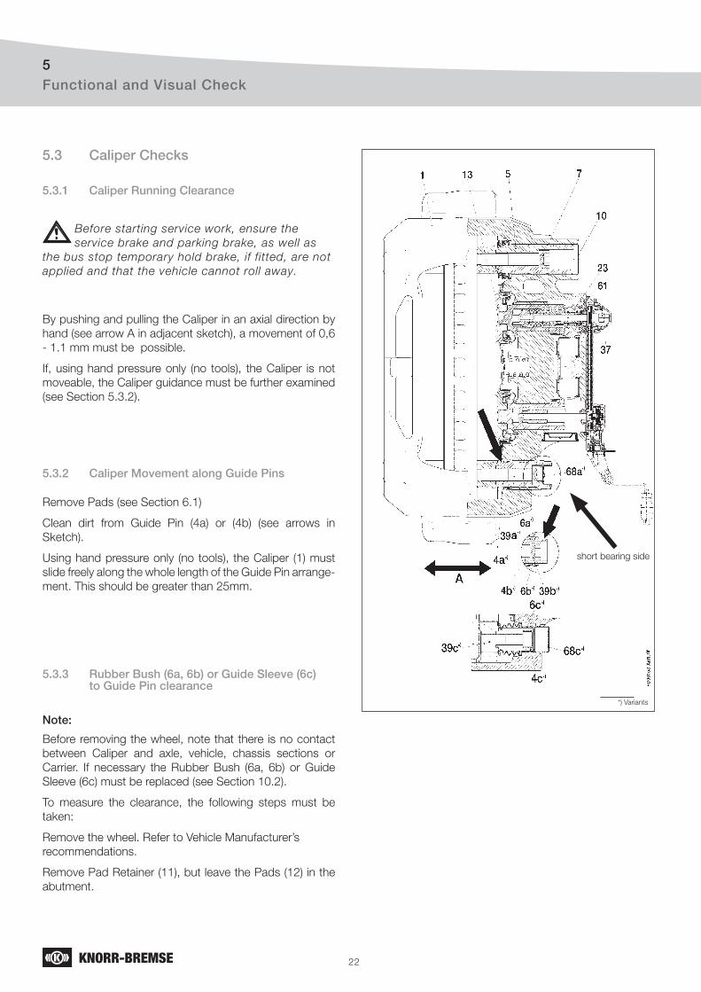
22
Functional and Visual Check5
5.3 Caliper Checks
5.3.1 Caliper Running Clearance
5.3.2 Caliper Movement along Guide Pins
By pushing and pulling the Caliper in an axial direction by
hand (see arrow A in adjacent sketch), a movement of 0,6
- 1.1 mm must be possible.
If, using hand pressure only (no tools), the Caliper is not
moveable, the Caliper guidance must be further examined
(see Section 5.3.2).
Remove Pads (see Section 6.1)
Clean dirt from Guide Pin (4a) or (4b) (see arrows in
Sketch).
Using hand pressure only (no tools), the Caliper (1) must
slide freely along the whole length of the Guide Pin arrange-
ment. This should be greater than 25mm.
5.3.3 Rubber Bush (6a, 6b) or Guide Sleeve (6c) to Guide Pin clearance
Note:
Before removing the wheel, note that there is no contact
between Caliper and axle, vehicle, chassis sections or
Carrier. If necessary the Rubber Bush (6a, 6b) or Guide
Sleeve (6c) must be replaced (see Section 10.2).
To measure the clearance, the following steps must be
taken:
Remove the wheel. Refer to Vehicle Manufacturer’s
recommendations.
Remove Pad Retainer (11), but leave the Pads (12) in the
abutment.
short bearing side
*) Variants
Before starting service work, ensure the
service brake and parking brake, as well as
the bus stop temporary hold brake, if fitted, are not
applied and that the vehicle cannot roll away.
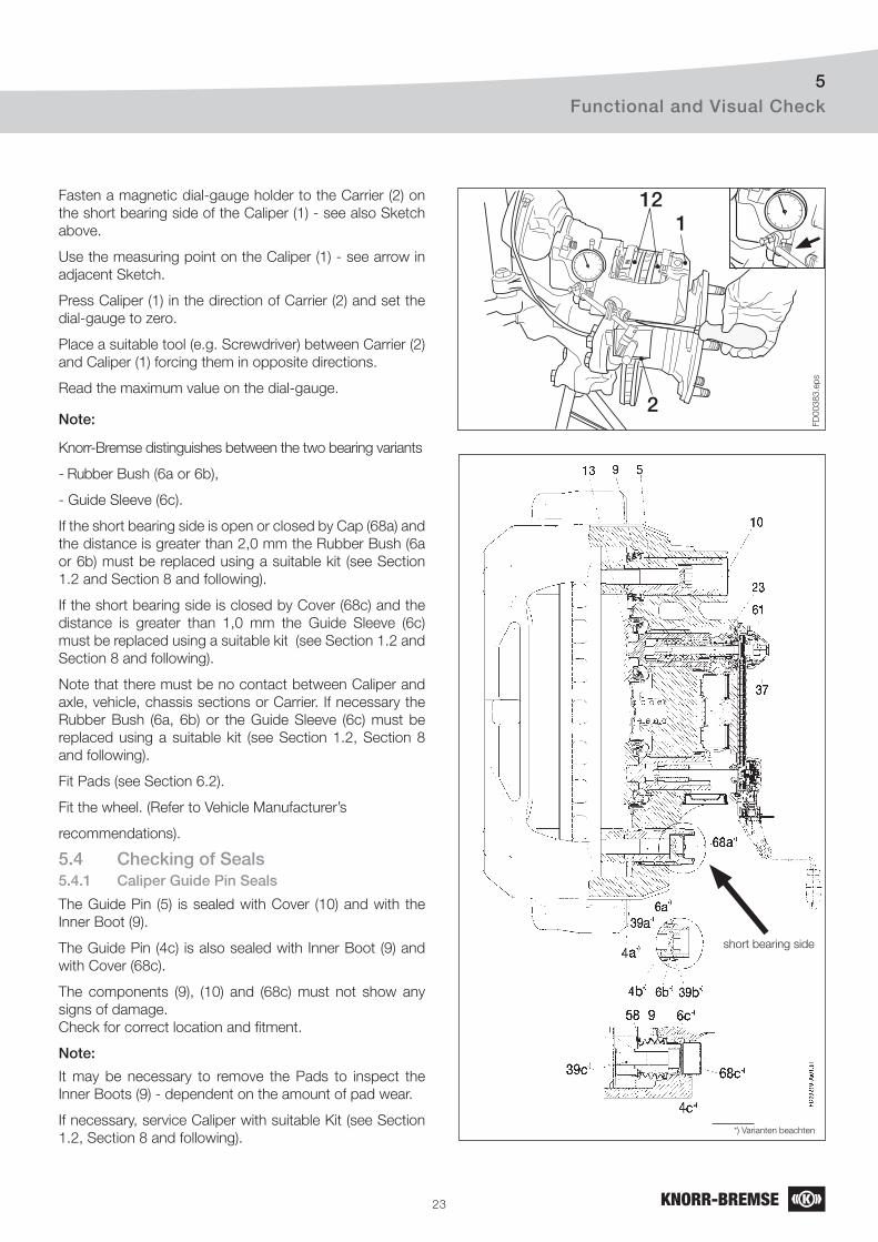
23
Functional and Visual Check5
FD
00383.e
ps
2
112Fasten a magnetic dial-gauge holder to the Carrier (2) on
the short bearing side of the Caliper (1) - see also Sketch
above.
Use the measuring point on the Caliper (1) - see arrow in
adjacent Sketch.
Press Caliper (1) in the direction of Carrier (2) and set the
dial-gauge to zero.
Place a suitable tool (e.g. Screwdriver) between Carrier (2)
and Caliper (1) forcing them in opposite directions.
Read the maximum value on the dial-gauge.
Note:
Knorr-Bremse distinguishes between the two bearing variants
- Rubber Bush (6a or 6b),
- Guide Sleeve (6c).
If the short bearing side is open or closed by Cap (68a) and
the distance is greater than 2,0 mm the Rubber Bush (6a
or 6b) must be replaced using a suitable kit (see Section
1.2 and Section 8 and following).
If the short bearing side is closed by Cover (68c) and the
distance is greater than 1,0 mm the Guide Sleeve (6c)
must be replaced using a suitable kit (see Section 1.2 and
Section 8 and following).
Note that there must be no contact between Caliper and
axle, vehicle, chassis sections or Carrier. If necessary the
Rubber Bush (6a, 6b) or the Guide Sleeve (6c) must be
replaced using a suitable kit (see Section 1.2, Section 8
and following).
Fit Pads (see Section 6.2).
Fit the wheel. (Refer to Vehicle Manufacturer’s
recommendations).
5.4 Checking of Seals 5.4.1 Caliper Guide Pin Seals
The Guide Pin (5) is sealed with Cover (10) and with the
Inner Boot (9).
The Guide Pin (4c) is also sealed with Inner Boot (9) and
with Cover (68c).
The components (9), (10) and (68c) must not show any
signs of damage.
Check for correct location and fi tment.
Note:
It may be necessary to remove the Pads to inspect the
Inner Boots (9) - dependent on the amount of pad wear.
If necessary, service Caliper with suitable Kit (see Section
1.2, Section 8 and following).
short bearing side
*) Varianten beachten

24
Functional and Visual Check5
30
FD
00220.e
ps
13
5.4.2 Checking of Tappet and Boot Assemblies (13)
If necessary remove Pads (12) (see Section 6.1) and screw
the Shear Adapter (61) clockwise (see Section 5.2) until the
boots are clearly visible.
Note:
The tappet should not extend more than 30 mm (see
sketch).
The Tappet and Boot Assemblies (13) must not show any
signs of damage.
Check for correct location and fi tment.
Note:
The penetration of dirt and moisture into the brake will lead
to corrosion and impair the function of the Disc Brake.
If necessary replace Tappet and Boot Assemblies (see
Section 7).
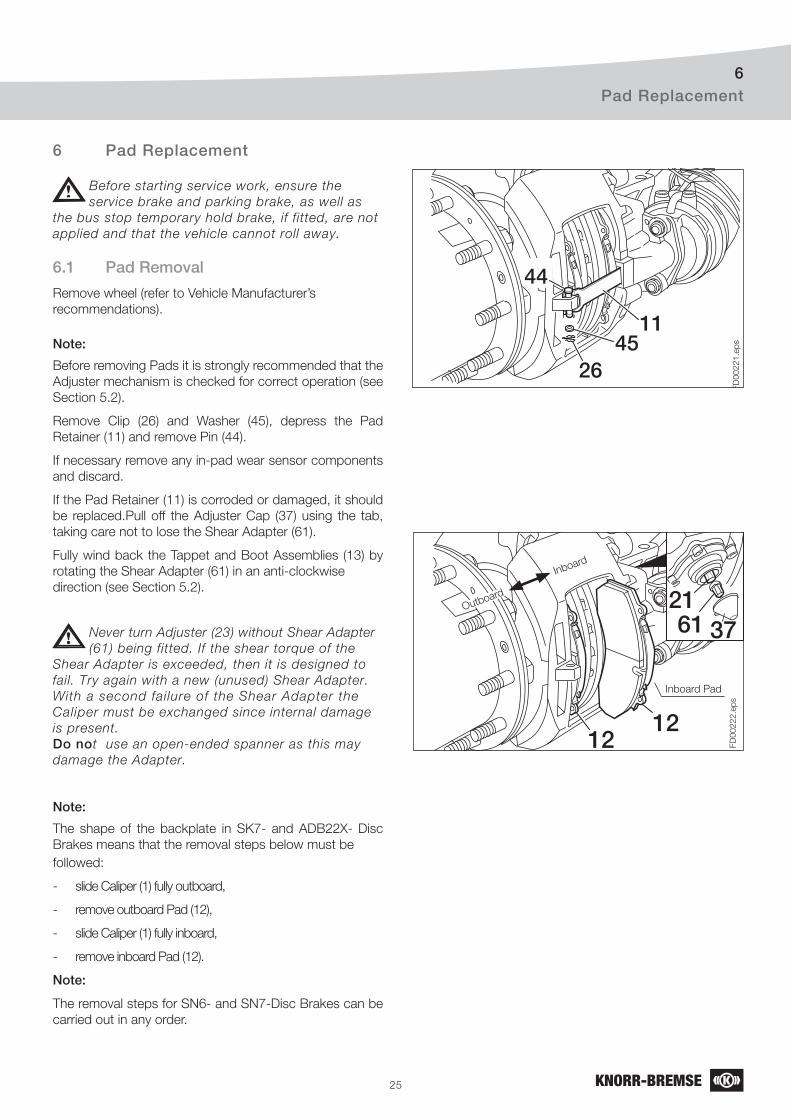
25
Pad Replacement6
6.1 Pad Removal
Remove wheel (refer to Vehicle Manufacturer’s
recommendations).
Note:
Before removing Pads it is strongly recommended that the
Adjuster mechanism is checked for correct operation (see
Section 5.2).
Remove Clip (26) and Washer (45), depress the Pad
Retainer (11) and remove Pin (44).
If necessary remove any in-pad wear sensor components
and discard.
If the Pad Retainer (11) is corroded or damaged, it should
be replaced.Pull off the Adjuster Cap (37) using the tab,
taking care not to lose the Shear Adapter (61).
Fully wind back the Tappet and Boot Assemblies (13) by
rotating the Shear Adapter (61) in an anti-clockwise
direction (see Section 5.2).
Never turn Adjuster (23) without Shear Adapter
(61) being fitted. If the shear torque of the
Shear Adapter is exceeded, then it is designed to
fail. Try again with a new (unused) Shear Adapter.
With a second failure of the Shear Adapter the
Caliper must be exchanged since internal damage
is present.
Do not use an open-ended spanner as this may
damage the Adapter.
Note:
The shape of the backplate in SK7- and ADB22X- Disc
Brakes means that the removal steps below must be
followed:
- slide Caliper (1) fully outboard,
- remove outboard Pad (12),
- slide Caliper (1) fully inboard,
- remove inboard Pad (12).
Note:
The removal steps for SN6- and SN7-Disc Brakes can be
carried out in any order.
FD
00221.e
ps
1145
26
44
FD
00222.e
ps
2337
3761
1212
21Outboard
Inboard
Inboard Pad
6 Pad Replacement
Before starting service work, ensure the
service brake and parking brake, as well as
the bus stop temporary hold brake, if fitted, are not
applied and that the vehicle cannot roll away.
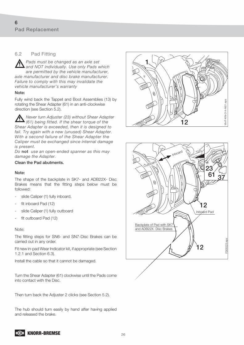
26
Pad Replacement6
6.2 Pad Fitting
Pads must be changed as an axle set
and NOT individually. Use only Pads which
are permitted by the vehicle manufacturer,
axle manufacturer and disc brake manufacturer.
Failure to comply with this may invalidate the
vehicle manufacturer’s warranty
Note:
Fully wind back the Tappet and Boot Assemblies (13) by
rotating the Shear Adapter (61) in an anti-clockwise
direction (see Section 5.2).
Clean the Pad abutments.
Note:
The shape of the backplate in SK7- and ADB22X- Disc
Brakes means that the fi tting steps below must be
followed:
- slide Caliper (1) fully inboard,
- fi t inboard Pad (12)
- slide Caliper (1) fully outboard
- fi t outboard Pad (12)
Note:
The fi tting steps for SN6- and SN7-Disc Brakes can be
carried out in any order.
Fit new in-pad Wear Indicator kit, if appropriate (see Section
1.2.1 and Section 6.3).
Install the cable so that it cannot be damaged.
Turn the Shear Adapter (61) clockwise until the Pads come
into contact with the Disc.
Then turn back the Adjuster 2 clicks (see Section 5.2).
The hub should turn easily by hand after having applied
and released the brake.
M+
P-K
N-0
14-Ä
i01.e
ps
12
1
FD
00
22
3.e
ps
2337
233761
12
12
Outboard
Inboard
Inboard Pad
Backplate of Pad with SK7
and ADB22X- Disc Brakes
Never turn Adjuster (23) without Shear Adapter
(61) being fitted. If the shear torque of the
Shear Adapter is exceeded, then it is designed to
fail. Try again with a new (unused) Shear Adapter.
With a second failure of the Shear Adapter the
Caliper must be exchanged since internal damage
is present.
Do not use an open-ended spanner as this may
damage the Adapter.
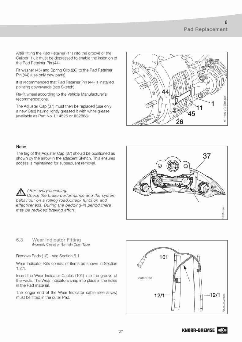
27
111
4526
44
M+
P-K
N-0
16-Ä
i01.e
ps
FD
00144.e
ps
37
Pad Replacement6
After fi tting the Pad Retainer (11) into the groove of the
Caliper (1), it must be depressed to enable the insertion of
the Pad Retainer Pin (44).
Fit washer (45) and Spring Clip (26) to the Pad Retainer
Pin (44) (use only new parts).
It is recommended that Pad Retainer Pin (44) is installed
pointing downwards (see Sketch).
Re-fi t wheel according to the Vehicle Manufacturer’s
recommendations.
The Adjuster Cap (37) must then be replaced (use only
a new Cap) having lightly greased it with white grease
(available as Part No. II14525 or II32868).
Note:
The tag of the Adjuster Cap (37) should be positioned as
shown by the arrow in the adjacent Sketch. This ensures
access is maintained for subsequent removal.
After every servicing:
Check the brake performance and the system
behaviour on a rolling road.Check function and
effectiveness. During the bedding-in period there
may be reduced braking effort.
6.3 Wear Indicator Fitting (Normally Closed or Normally Open Type)
Remove Pads (12) - see Section 6.1.
Wear Indicator Kits consist of items as shown in Section
1.2.1.
Insert the Wear Indicator Cables (101) into the groove of
the Pads. The Wear Indicators snap into place in the holes
in the Pad material.
The longer end of the Wear Indicator cable (see arrow)
must be fi tted in the outer Pad.
101
12/112/1
FD
00
23
7/2
.ep
s
outer Pad
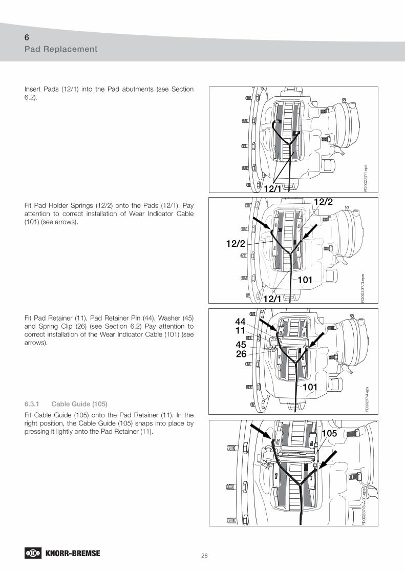
28
Pad Replacement6
FD
00
23
7/1
.ep
s
12/1
FD
00
23
7/3
.ep
s
12/2
12/2
12/1
101
FD
00
23
7/4
.ep
s
4411
4526
101
FD
00237/5
-Äi0
1.e
ps
105
Insert Pads (12/1) into the Pad abutments (see Section
6.2).
Fit Pad Holder Springs (12/2) onto the Pads (12/1). Pay
attention to correct installation of Wear Indicator Cable
(101) (see arrows).
Fit Pad Retainer (11), Pad Retainer Pin (44), Washer (45)
and Spring Clip (26) (see Section 6.2) Pay attention to
correct installation of the Wear Indicator Cable (101) (see
arrows).
6.3.1 Cable Guide (105)
Fit Cable Guide (105) onto the Pad Retainer (11). In the
right position, the Cable Guide (105) snaps into place by
pressing it lightly onto the Pad Retainer (11).
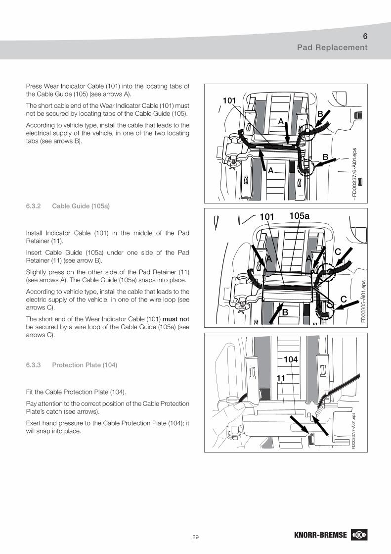
29
Pad Replacement6
FD
00
23
7/6
-Äi0
1.e
ps
A
A
B
B
101
FD
00305-Ä
i01.e
ps
C
C
105a
B
A A
101
FD
00
23
7/7
-Äi0
1.e
ps
104
11
Press Wear Indicator Cable (101) into the locating tabs of
the Cable Guide (105) (see arrows A).
The short cable end of the Wear Indicator Cable (101) must
not be secured by locating tabs of the Cable Guide (105).
According to vehicle type, install the cable that leads to the
electrical supply of the vehicle, in one of the two locating
tabs (see arrows B).
6.3.2 Cable Guide (105a)
Install Indicator Cable (101) in the middle of the Pad
Retainer (11).
Insert Cable Guide (105a) under one side of the Pad
Retainer (11) (see arrow B).
Slightly press on the other side of the Pad Retainer (11)
(see arrows A). The Cable Guide (105a) snaps into place.
According to vehicle type, install the cable that leads to the
electric supply of the vehicle, in one of the wire loop (see
arrows C).
The short end of the Wear Indicator Cable (101) must not be secured by a wire loop of the Cable Guide (105a) (see
arrows C).
6.3.3 Protection Plate (104)
Fit the Cable Protection Plate (104).
Pay attention to the correct position of the Cable Protection
Plate’s catch (see arrows).
Exert hand pressure to the Cable Protection Plate (104); it
will snap into place.
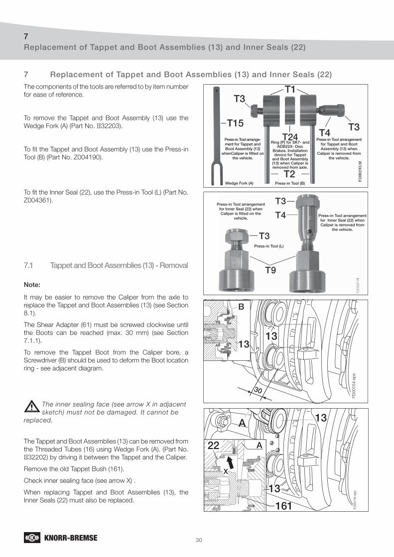
30
Replacement of Tappet and Boot Assemblies (13) and Inner Seals (22)7
FD
00154.e
ps
30
1313
B
A 13
FD
00
15
5.e
ps133
A
161
X
22 A
X
22
Press-in Tool arrange-ment for Tappet and Boot Assembly (13)
whenCaliper is fi tted on the vehicle.
Wedge Fork (A) Press-in Tool (B)
Ring (P) for SK7- and ADB22X- Disc
Brakes. Installation device for Tappet
and Boot Assembly (13) when Caliper is removed from axle.
Press-in Tool arrangement for Tappet and Boot Assembly (13) when
Caliper is removed from the vehicle.
Press-in Tool (L)
Press-in Tool arrangement for Inner Seal (22) when Caliper is fi tted on the
vehicle.Press-in Tool arrangement for Inner Seal (22) when Caliper is removed from
the vehicle.
The components of the tools are referred to by item number
for ease of reference.
To remove the Tappet and Boot Assembly (13) use the
Wedge Fork (A) (Part No. II32203).
To fi t the Tappet and Boot Assembly (13) use the Press-in
Tool (B) (Part No. Z004190).
To fi t the Inner Seal (22), use the Press-in Tool (L) (Part No.
Z004361).
7.1 Tappet and Boot Assemblies (13) - Removal
Note:
It may be easier to remove the Caliper from the axle to
replace the Tappet and Boot Assemblies (13) (see Section
8.1).
The Shear Adapter (61) must be screwed clockwise until
the Boots can be reached (max. 30 mm) (see Section
7.1.1).
To remove the Tappet Boot from the Caliper bore, a
Screwdriver (B) should be used to deform the Boot location
ring - see adjacent diagram.
The inner sealing face (see arrow X in adjacent
sketch) must not be damaged. It cannot be
replaced.
The Tappet and Boot Assemblies (13) can be removed from
the Threaded Tubes (16) using Wedge Fork (A). (Part No.
II32202) by driving it between the Tappet and the Caliper.
Remove the old Tappet Bush (161).
Check inner sealing face (see arrow X) .
When replacing Tappet and Boot Assemblies (13), the
Inner Seals (22) must also be replaced.
7 Replacement of Tappet and Boot Assemblies (13) and Inner Seals (22)
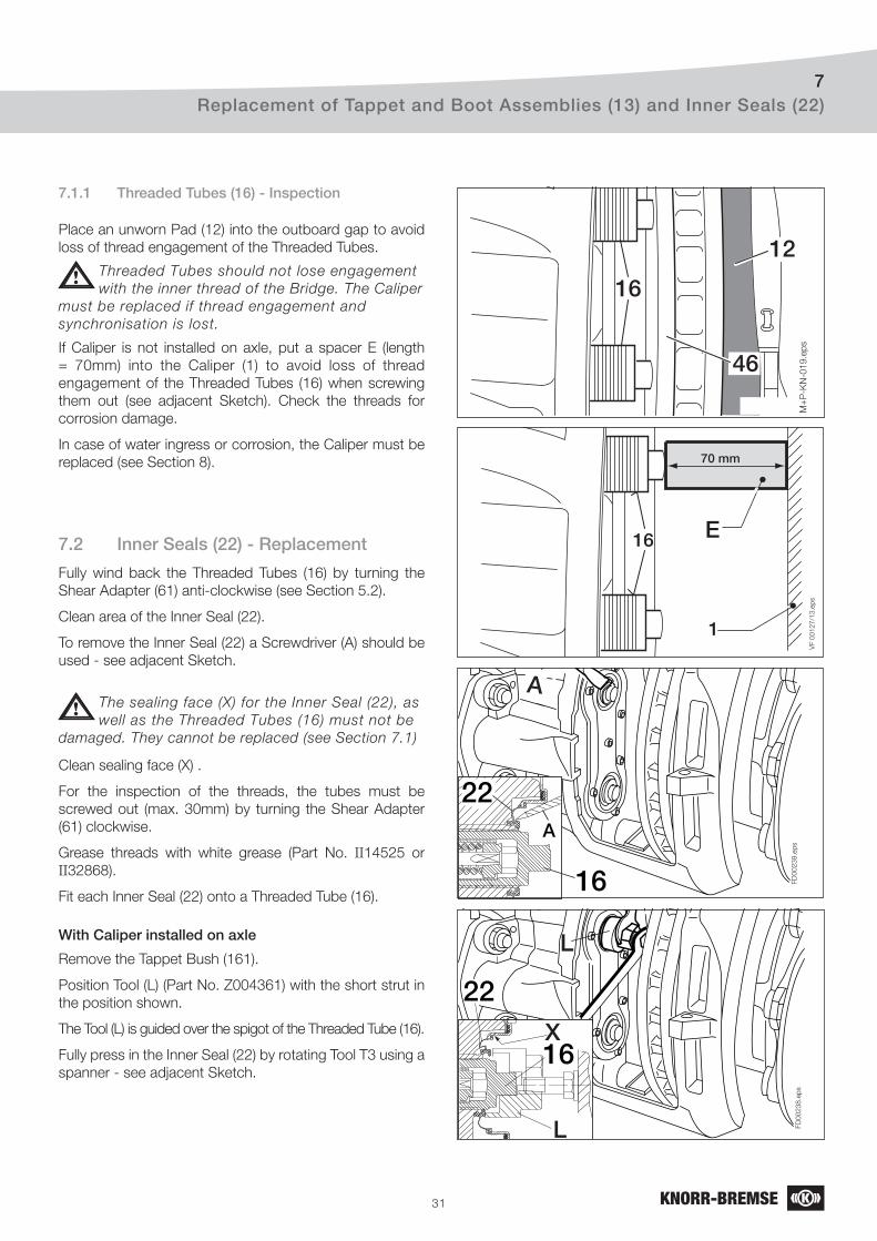
31
Replacement of Tappet and Boot Assemblies (13) and Inner Seals (22)7
M+
P-K
N-0
19
.ep
s
12
46
16
VF 0
0127/1
3.e
ps
16
1
70 mm
E
A
FD
00
23
9.e
ps
A
22
16
L
FD
00
23
8.e
ps
22
L
X16
7.1.1 Threaded Tubes (16) - Inspection
Place an unworn Pad (12) into the outboard gap to avoid
loss of thread engagement of the Threaded Tubes.
Threaded Tubes should not lose engagement
with the inner thread of the Bridge. The Caliper
must be replaced if thread engagement and
synchronisation is lost.
If Caliper is not installed on axle, put a spacer E (length
= 70mm) into the Caliper (1) to avoid loss of thread
engagement of the Threaded Tubes (16) when screwing
them out (see adjacent Sketch). Check the threads for
corrosion damage.
In case of water ingress or corrosion, the Caliper must be
replaced (see Section 8).
7.2 Inner Seals (22) - Replacement
Fully wind back the Threaded Tubes (16) by turning the
Shear Adapter (61) anti-clockwise (see Section 5.2).
Clean area of the Inner Seal (22).
To remove the Inner Seal (22) a Screwdriver (A) should be
used - see adjacent Sketch.
The sealing face (X) for the Inner Seal (22), as
well as the Threaded Tubes (16) must not be
damaged. They cannot be replaced (see Section 7.1)
Clean sealing face (X) .
For the inspection of the threads, the tubes must be
screwed out (max. 30mm) by turning the Shear Adapter
(61) clockwise.
Grease threads with white grease (Part No. II14525 or
II32868).
Fit each Inner Seal (22) onto a Threaded Tube (16).
With Caliper installed on axle
Remove the Tappet Bush (161).
Position Tool (L) (Part No. Z004361) with the short strut in
the position shown.
The Tool (L) is guided over the spigot of the Threaded Tube (16).
Fully press in the Inner Seal (22) by rotating Tool T3 using a
spanner - see adjacent Sketch.

32
Replacement of Tappet and Boot Assemblies (13) and Inner Seals (22)7
FD
00
24
0.e
ps
22
LX16
L
B
FD
00
156
.ep
s
161
13
Sketch 1
FD
00225.e
ps
B13
Sketch 2
To check the correct fi t of the Inner Seal (22), screw out
the Threaded Tubes (16) about 4-5 threads by turning the
Shear Adapter (61) clockwise.
The Inner Seal (22) must not turn.
With Caliper not installed on axle
The fi tting sequence of Inner Seal (22) does not change.
When pressing in the Inner Seal (22) however, use the long
strut (T3+T4) for Tool (L) (Part No. Z004361) - see page
28.
7.3 Tappet and Boot Assemblies (13) - Fitting
With Caliper installed on axle
The Threaded Tubes (16) must be fully wound back (see
Section 5.2).
The sealing seat in the caliper for Tappet and Boot
Assemblies (13) must be clean and free of grease.
Fit a new Tappet Bush (161) onto the spigot of each
Threaded Tube (16).
Position a Tappet and Boot Assembly (13) onto each
Tappet Bush.
Use Push-in Tool (B) (Part No. Z004190) with the short
strut (T3) for positioning and pressing in the Boot - see
Sketch 1.
Using Tool (B) (Part No. Z004190) in reverse, with the short
strut (T3), each Tappet can be pressed onto its Tappet
Bush - see Sketch 2.
After assembly the Tappet (13) must be free to turn in both
directions.
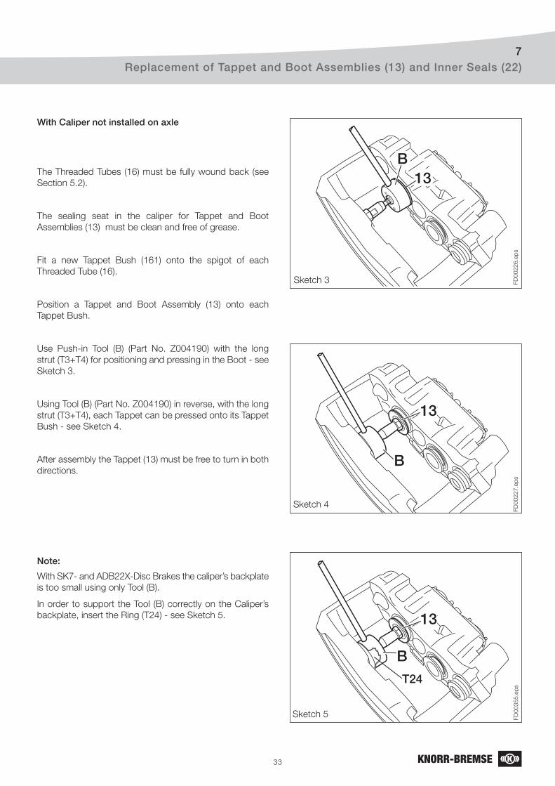
33
Replacement of Tappet and Boot Assemblies (13) and Inner Seals (22)7
FD
00226.e
ps
B13
Sketch 3
FD
00227.e
ps
B
13
Sketch 4
FD
00355.e
ps
B
13
T24
Sketch 5
With Caliper not installed on axle
The Threaded Tubes (16) must be fully wound back (see
Section 5.2).
The sealing seat in the caliper for Tappet and Boot
Assemblies (13) must be clean and free of grease.
Fit a new Tappet Bush (161) onto the spigot of each
Threaded Tube (16).
Position a Tappet and Boot Assembly (13) onto each
Tappet Bush.
Use Push-in Tool (B) (Part No. Z004190) with the long
strut (T3+T4) for positioning and pressing in the Boot - see
Sketch 3.
Using Tool (B) (Part No. Z004190) in reverse, with the long
strut (T3+T4), each Tappet can be pressed onto its Tappet
Bush - see Sketch 4.
After assembly the Tappet (13) must be free to turn in both
directions.
Note:
With SK7- and ADB22X-Disc Brakes the caliper’s backplate
is too small using only Tool (B).
In order to support the Tool (B) correctly on the Caliper’s
backplate, insert the Ring (T24) - see Sketch 5.

34
Caliper Replacement8
FD
00398.e
ps
68c
The components of the tools are referred to by item number
for ease of reference.
To fi t the Cap (68a), use the Press-in Tool (K) (Part No.
Z003934).
To fi t the Cover (68c), use the Press-in Tool (M) (Part No.
K016743).
To fi t the Cover (10) use Press-in Tool (H) (Part No.
K015825).
8.1 Caliper Removal
Remove Pads (12) (see Section 6.1).
Remove Actuator (see Section 12.1, 12.3).
If fi tted, remove Wear Indicator Cable or Cable to built-in
Potentiometer.
Do not touch electrical contact points because
of static discharge!
Note:
It may be necessary for reasons of accessibility to remove
the Caliper and Carrier from the axle (refer to Vehicle
Manufacturer’s recommendations) or remove only the
Caliper.
8.1.1 Removal of the Cover (10) Use a suitable Tool (e.g a Screwdriver) to penetrate the Cover (10).
During penetration, the Cover may move approximately 10 mm inwards.
Remove Cover (10).
Cover (10) should be penetrated in the
middle. Do not drive the tool between Caliper
bore and Cover (10) since Caliper bore may be
damaged.
Check the Caliper bore for the cover (10), as well as the
inner bearing bore for dirt and corrosion. If necessary the
Caliper must be replaced.
8.1.2 Removal of the Cover (68c)
Because of the protruding Cover (68c) it must be
dissasembled as shown in adjacent Sketch. Use a
srewdriver or another suitable tool.
Do not dissasemble the Cover (68c) in direction of the Caliper
since itself or components of it might be damaged.
Check the Caliper bore for the cover (68c) , as well as the
inner bearing bore for dirt and corrosion. If necessary the
Caliper must be replaced.
8 Caliper Replacement
T11
T26
T27
Press- in Tool (K)
Tool for
pressing in
the Cap (68a)
Tool for
pressing in
the Cover (68c)
FD
00161-Ä
i01.e
ps
10
X
V
10
Press- in Tool (M)
Press- in Tool (H)
Tool for
pressing in
the Cover (10)

35
Caliper Replacement8
401039a*
68a* )
)
39c*
68c* )
)
FD
00208-Ä
i01.e
ps
B
A
8.1.3 Removal of Cap (68a)
On Calipers with Rubber Bush (6a), pull the Cap (68a) from
the Guide Pin (4) using a suitable tool (see Sketch).
Take care not to damage Rubber Bush (6a). If
necessary replace it by means of a Guide Pins and
Seals Kit.
8.1.4 Remove Caliper from Carrier
Before removing the Caliper Bolts (39 and 40)
ensure that the Caliper (1) cannot move or fall when
the Caliper Bolts are removed causing damage or injury.
Remove Caliper Bolts (39) and (40) and discard. They must not be re-used.
Never hold the Caliper with your fi ngers between
Caliper and Carrier - there is a risk of injury! Do not
fasten any lifting device to the Pad Retainer (11), since this
could be damaged.
The opening or dismantling of the Caliper is not
authorised. Use only genuine Knorr-Bremse
replacement Calipers.
The correct choice of Caliper must be ensured by checking
the part number on the identifi cation label (see arrow A in
sketch 1 and Section 1.2).
The replacement Caliper may have a plastic cap or adhesive
tape in the area of the actuator attachment (see arrow B
in sketch 1). Remove the cap or tape after installing the
caliper on the vehicle. Alternatively, if the replacement
Caliper has a breakthrough diaphragm, it should be left in
place (see arrow in sketch down).
Note:
The replacement Caliper includes Seals and Guide Pins.
The Pads are not included.
If the replacement Caliper is equipped with a potentiometer,
then the connection must be made using the appropriate
mating plug - refer to Vehicle Manufacturer’s recommendations.
Never hold the Caliper with your fi ngers between
Caliper and Carrier - there is a risk of injury! Do not
fasten any lifting device to the Pad Retainer (11), since this
could be damaged.
Remove Caliper from Carrier.
8.2 Caliper Fitting (Carrier is fi tted on the axle)

36
4010
39c*
68c* )
)
FD
0035
6.ep
s
4c*)
52
1
FD
00
22
8.e
ps
58
9
5
The Guide Pins (4 and 5) as well as the Caliper
Bolts (39 and 40) are highly stressed items.
They must be replaced whenever the Caliper (1) is
removed from the Carrier (2).
Fit the Caliper to the Carrier.
Screw in new Caliper Bolts (39) and (40) and tighten to 180 Nm, then tighten by a further 90°.
Screw threads and tapped holes must be clean and
dry (free of lubrication and residuals of pre-applied
adhesive).
Check that the Caliper slides easily on the Guide Pins.
Check the position of the Inner Boot (9) on the Guide Pin
(5). According to the Caliper variant check also the position
on the Guide Pin (4) as well as the position of Ring (58).
Fit Pads (see Section 6.2).
Check Adjuster function (see Section 5.2).
Attach Brake Chamber or Spring Brake (see Section 12.2
or 12.4).
8.2.1 Fitting of Cover (10) and (68c)
Caliper bores and Covers (10) and (68c) must be clean and
free from lubrication.
Clean the new Cover (10) and (68c) thoroughly and check
that the face and the chamfer are clean and not damaged
- see arrows in fi gure below right.
Clean the interior of the Press-in tool (H) or (M) and place
the Cover (10) or (68c) inside - see adjacent fi gure.
Position the Press-in tool (H) or (M) including Cover (10) or
(68c) to the start of the caliper bore. Press on the mandrel
of the Press-in tool (H) or (M) by hand until resistence is
felt.
Note:
Do not tilt the tools when assembling the Covers (10) and
(68c) - see adjacent fi gure.
H, (M)
10,(68c)
Caliper Replacement8
FD
00538.e
ps
MH10 68c
XX
V V
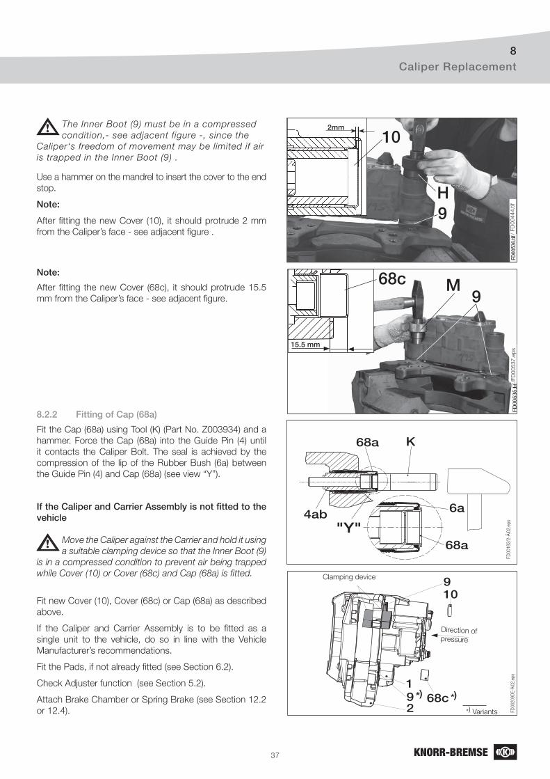
37
68a K
68a
6a
"Y"
FD
00
18
2/2
-Äi0
2.e
ps
4ab
9
FD
00
20
9D
E-Ä
i02
.ep
s
10
2
168c9*) *)
Direction of pressure
Clamping device
*) Variants
8.2.2 Fitting of Cap (68a)
Fit the Cap (68a) using Tool (K) (Part No. Z003934) and a
hammer. Force the Cap (68a) into the Guide Pin (4) until
it contacts the Caliper Bolt. The seal is achieved by the
compression of the lip of the Rubber Bush (6a) between
the Guide Pin (4) and Cap (68a) (see view “Y”).
If the Caliper and Carrier Assembly is not fi tted to the vehicle
Use a hammer on the mandrel to insert the cover to the end
stop.
Note:
After fi tting the new Cover (10), it should protrude 2 mm
from the Caliper’s face - see adjacent fi gure .
Note:
After fi tting the new Cover (68c), it should protrude 15.5
mm from the Caliper’s face - see adjacent fi gure.
Caliper Replacement8
The Inner Boot (9) must be in a compressed
condition,- see adjacent figure -, since the
Caliper‘s freedom of movement may be limited if air
is trapped in the Inner Boot (9) .
Move the Caliper against the Carrier and hold it using
a suitable clamping device so that the Inner Boot (9)
is in a compressed condition to prevent air being trapped
while Cover (10) or Cover (68c) and Cap (68a) is fi tted.
Fit new Cover (10), Cover (68c) or Cap (68a) as described
above.
If the Caliper and Carrier Assembly is to be fi tted as a
single unit to the vehicle, do so in line with the Vehicle
Manufacturer’s recommendations.
Fit the Pads, if not already fi tted (see Section 6.2).
Check Adjuster function (see Section 5.2).
Attach Brake Chamber or Spring Brake (see Section 12.2
or 12.4).
9H
2mm
10
/ FD
00444.t
if
99
15.5 mm
68c M
/FD
00537.e
ps
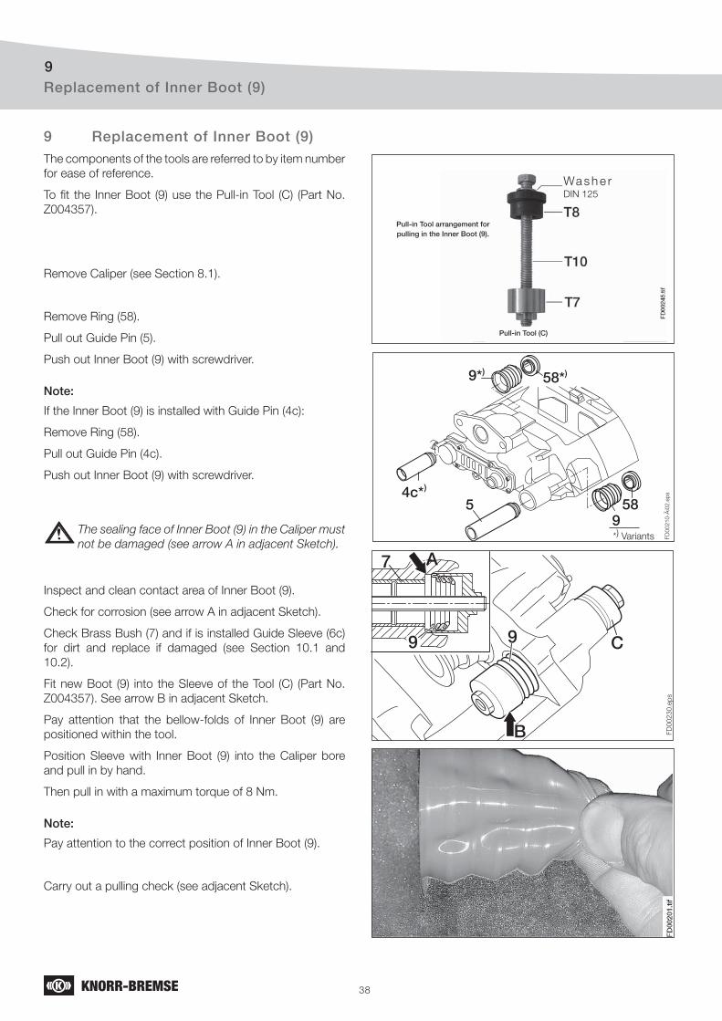
38
Replacement of Inner Boot (9)9
59
58
FD
00
21
0-Ä
i02
.ep
s4c*)
58*))9*
FD
00
23
0.e
ps
99
7 A
B
C
Pull-in Tool arrangement for pulling in the Inner Boot (9).
Wa s h e r DIN 125
The components of the tools are referred to by item number
for ease of reference.
To fi t the Inner Boot (9) use the Pull-in Tool (C) (Part No.
Z004357).
Remove Caliper (see Section 8.1).
Remove Ring (58).
Pull out Guide Pin (5).
Push out Inner Boot (9) with screwdriver.
Note:
If the Inner Boot (9) is installed with Guide Pin (4c):
Remove Ring (58).
Pull out Guide Pin (4c).
Push out Inner Boot (9) with screwdriver.
The sealing face of Inner Boot (9) in the Caliper must
not be damaged (see arrow A in adjacent Sketch).
Inspect and clean contact area of Inner Boot (9).
Check for corrosion (see arrow A in adjacent Sketch).
Check Brass Bush (7) and if is installed Guide Sleeve (6c)
for dirt and replace if damaged (see Section 10.1 and
10.2).
Fit new Boot (9) into the Sleeve of the Tool (C) (Part No.
Z004357). See arrow B in adjacent Sketch.
Pay attention that the bellow-folds of Inner Boot (9) are
positioned within the tool.
Position Sleeve with Inner Boot (9) into the Caliper bore
and pull in by hand.
Then pull in with a maximum torque of 8 Nm.
Note:
Pay attention to the correct position of Inner Boot (9).
Carry out a pulling check (see adjacent Sketch).
9 Replacement of Inner Boot (9)
Pull-in Tool (C)
*) Variants
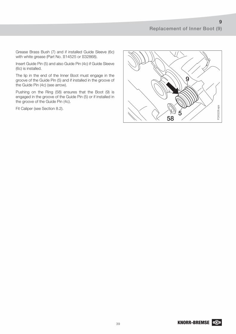
39
Replacement of Inner Boot (9)9
FD
00
22
8.e
ps
58
9
5
Grease Brass Bush (7) and if installed Guide Sleeve (6c)
with white grease (Part No. II14525 or II32868).
Insert Guide Pin (5) and also Guide Pin (4c) if Guide Sleeve
(6c) is installed.
The lip in the end of the Inner Boot must engage in the
groove of the Guide Pin (5) and if installed in the groove of
the Guide Pin (4c) (see arrow).
Pushing on the Ring (58) ensures that the Boot (9) is
engaged in the groove of the Guide Pin (5) or if installed in
the groove of the Guide Pin (4c).
Fit Caliper (see Section 8.2).
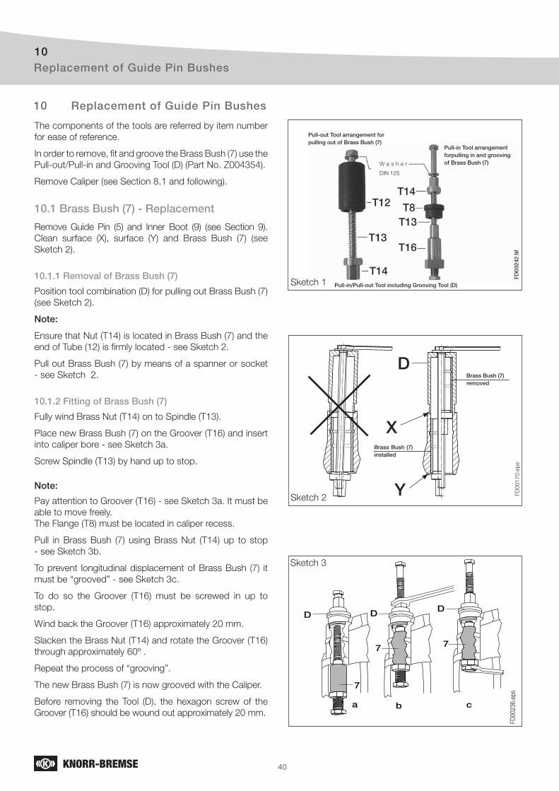
40
Replacement of Guide Pin Bushes10
FD
00
17
0.e
ps
FD
00236.e
ps
7
7 7
D D D
a b c
Pull-in Tool arrangement forpulling in and grooving of Brass Bush (7)W a s h e r
DIN 125
Pull-out Tool arrangement for pulling out of Brass Bush (7)
Pull-in/Pull-out Tool including Grooving Tool (D)Sketch 1
Sketch 2
D
X
Y
Brass Bush (7) installed
Brass Bush (7) removed
Sketch 3
The components of the tools are referred by item number
for ease of reference.
In order to remove, fi t and groove the Brass Bush (7) use the
Pull-out/Pull-in and Grooving Tool (D) (Part No. Z004354).
Remove Caliper (see Section 8.1 and following).
10.1 Brass Bush (7) - Replacement
Remove Guide Pin (5) and Inner Boot (9) (see Section 9).
Clean surface (X), surface (Y) and Brass Bush (7) (see
Sketch 2).
10.1.1 Removal of Brass Bush (7)
Position tool combination (D) for pulling out Brass Bush (7)
(see Sketch 2).
Note:
Ensure that Nut (T14) is located in Brass Bush (7) and the
end of Tube (12) is fi rmly located - see Sketch 2.
Pull out Brass Bush (7) by means of a spanner or socket
- see Sketch 2.
10.1.2 Fitting of Brass Bush (7)
Fully wind Brass Nut (T14) on to Spindle (T13).
Place new Brass Bush (7) on the Groover (T16) and insert
into caliper bore - see Sketch 3a.
Screw Spindle (T13) by hand up to stop.
Note:
Pay attention to Groover (T16) - see Sketch 3a. It must be
able to move freely.
The Flange (T8) must be located in caliper recess.
Pull in Brass Bush (7) using Brass Nut (T14) up to stop
- see Sketch 3b.
To prevent longitudinal displacement of Brass Bush (7) it
must be “grooved” - see Sketch 3c.
To do so the Groover (T16) must be screwed in up to
stop.
Wind back the Groover (T16) approximately 20 mm.
Slacken the Brass Nut (T14) and rotate the Groover (T16)
through approximately 60º .
Repeat the process of “grooving”.
The new Brass Bush (7) is now grooved with the Caliper.
Before removing the Tool (D), the hexagon screw of the
Groover (T16) should be wound out approximately 20 mm.
10 Replacement of Guide Pin Bushes

41
Replacement of Guide Pin Bushes10
Pull-in Tool arrangement for pulling in the Rubber
Bush (6a) or (6b)
Washer
DIN 125
Pull-out Tool arrangement for pulling out the Rubber
Bush (6a) or (6b)
Discs
Pull-in / Pull-out Tool (R)
Threaded Pin
DIN 915
R
R
Check contact area of Brass Bush (7) and remove any burrs.
Grease Bush (7) with white Grease (Part No. II14525 or
II32868).
10.2 Rubber Bush (6a or 6b) and Guide Sleeve (6c) - Replacement
The components of the tools are referred by item number
for ease of reference.
Use Tool (R) (Part No. Z004198) for the assembly of the
Rubber Bush (6a or 6b), (see adjacent sketch).
Note:
Do not use the Disc T5 Ø35 with SN- Type.
Use Tool (N) (Part No. K005986) for the assembly of the
Guide Sleeve (6c) (see adjacent sketch).
10.2.1 Removal of Rubber Bush (6a or 6b)
Remove Guide Pin (4a or 4b).
Clean Caliper in the area of the Rubber Bush.
Select Disc T6 Ø39.
Position the Tool (R) (Part No. Z004198) as shown in the
adjacent picture. Screw on the Nut (T22) by hand.
Hold the Nut (T22) with a ring spanner and with a suitable
socket or ring spanner tighten Spindle (T20) to remove the
Rubber Bush.
Pull-out Toolarrangement for pulling out the Guide
Sleeve (6c)
Pull-in Toolarrangement for pulling in the Guide
Sleeve (6c)
Washer
DIN 125
T05
T06
T08
T20
T14
T21
Pull-in / Pull-out Tool (N)
Pay attention to suitable Disc Ø39 !
R
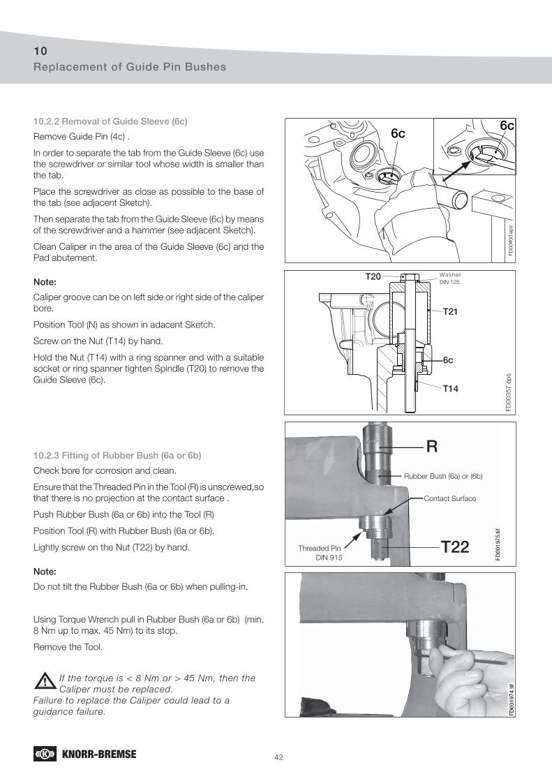
42
Replacement of Guide Pin Bushes10
FD
00
40
0.e
ps
6c6c
FD
00
35
7.e
ps
T20
6c
T21
T14
Washer
DIN 125
10.2.2 Removal of Guide Sleeve (6c)
Remove Guide Pin (4c) .
In order to separate the tab from the Guide Sleeve (6c) use
the screwdriver or similar tool whose width is smaller than
the tab.
Place the screwdriver as close as possible to the base of
the tab (see adjacent Sketch).
Then separate the tab from the Guide Sleeve (6c) by means
of the screwdriver and a hammer (see adjacent Sketch).
Clean Caliper in the area of the Guide Sleeve (6c) and the
Pad abutement.
Note:
Caliper groove can be on left side or right side of the caliper
bore.
Position Tool (N) as shown in adacent Sketch.
Screw on the Nut (T14) by hand.
Hold the Nut (T14) with a ring spanner and with a suitable
socket or ring spanner tighten Spindle (T20) to remove the
Guide Sleeve (6c).
10.2.3 Fitting of Rubber Bush (6a or 6b)
Check bore for corrosion and clean.
Ensure that the Threaded Pin in the Tool (R) is unscrewed,so
that there is no projection at the contact surface .
Push Rubber Bush (6a or 6b) into the Tool (R)
Position Tool (R) with Rubber Bush (6a or 6b).
Lightly screw on the Nut (T22) by hand.
Note:
Do not tilt the Rubber Bush (6a or 6b) when pulling-in.
Using Torque Wrench pull in Rubber Bush (6a or 6b) (min.
8 Nm up to max. 45 Nm) to its stop.
Remove the Tool.
If the torque is < 8 Nm or > 45 Nm, then the
Caliper must be replaced.
Failure to replace the Caliper could lead to a
guidance failure.
RRubber Bush (6a) or (6b)
Contact Surface
Threaded Pin
DIN 915T22
R
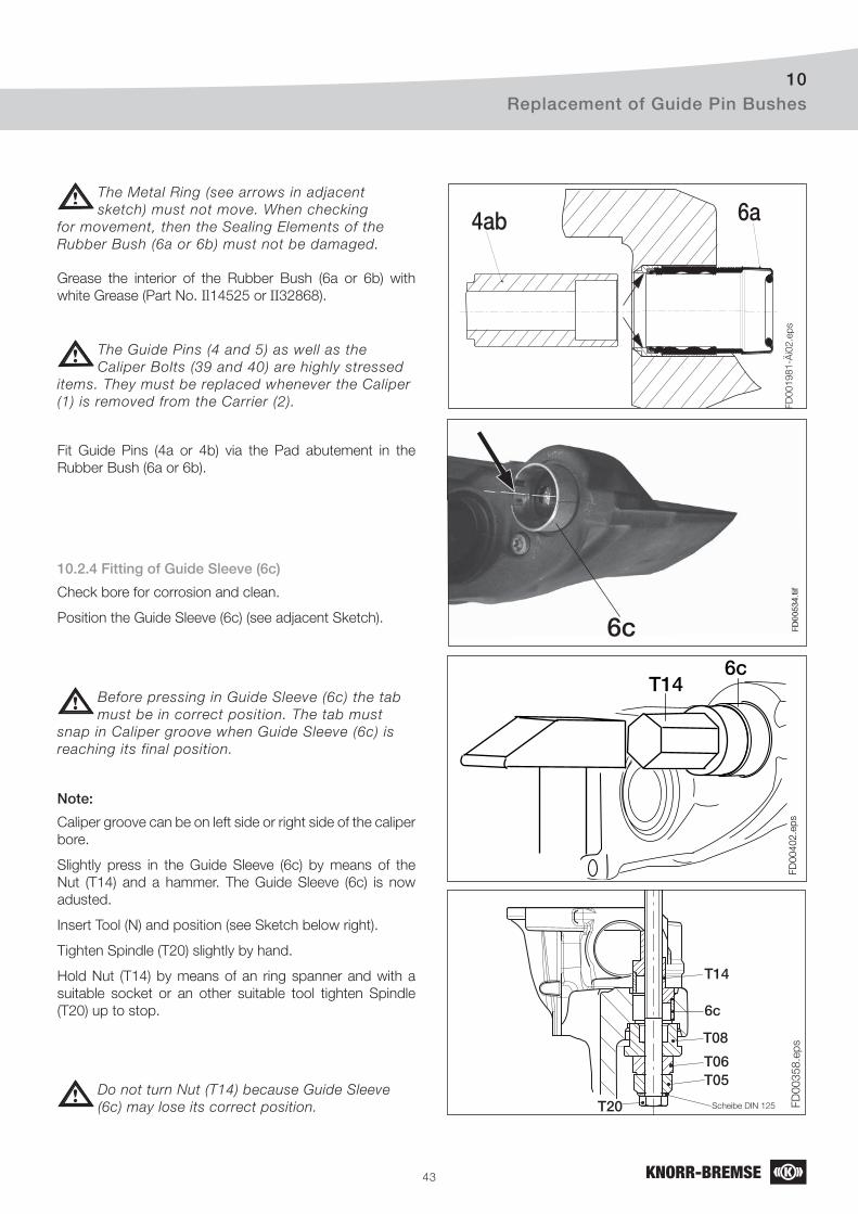
43
Replacement of Guide Pin Bushes10
FD
00
40
2.e
ps
T146c
FD
001981-Ä
i02.e
ps
4ab 6a
FD
00
35
8.e
ps
T14
6c
T08
T06T05
T20 Scheibe DIN 125
The Metal Ring (see arrows in adjacent
sketch) must not move. When checking
for movement, then the Sealing Elements of the
Rubber Bush (6a or 6b) must not be damaged.
Grease the interior of the Rubber Bush (6a or 6b) with
white Grease (Part No. Il14525 or II32868).
The Guide Pins (4 and 5) as well as the
Caliper Bolts (39 and 40) are highly stressed
items. They must be replaced whenever the Caliper
(1) is removed from the Carrier (2).
Fit Guide Pins (4a or 4b) via the Pad abutement in the
Rubber Bush (6a or 6b).
10.2.4 Fitting of Guide Sleeve (6c)
Check bore for corrosion and clean.
Position the Guide Sleeve (6c) (see adjacent Sketch).
Before pressing in Guide Sleeve (6c) the tab
must be in correct position. The tab must
snap in Caliper groove when Guide Sleeve (6c) is
reaching its final position.
Note:
Caliper groove can be on left side or right side of the caliper
bore.
Slightly press in the Guide Sleeve (6c) by means of the
Nut (T14) and a hammer. The Guide Sleeve (6c) is now
adusted.
Insert Tool (N) and position (see Sketch below right).
Tighten Spindle (T20) slightly by hand.
Hold Nut (T14) by means of an ring spanner and with a
suitable socket or an other suitable tool tighten Spindle
(T20) up to stop.
Do not turn Nut (T14) because Guide Sleeve
(6c) may lose its correct position.
6c
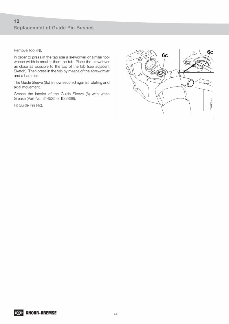
44
FD
00
40
3.e
ps
6c6cRemove Tool (N).
In order to press in the tab use a srewdriver or similar tool
whose width is smaller than the tab. Place the srewdriver
as close as possible to the top of the tab (see adjacent
Sketch). Then press in the tab by means of the screwdriver
and a hammer.
The Guide Sleeve (6c) is now secured against rotating and
axial movement.
Grease the interior of the Guide Sleeve (6) with white
Grease (Part No. Il14525 or II32868).
Fit Guide Pin (4c).
Replacement of Guide Pin Bushes10
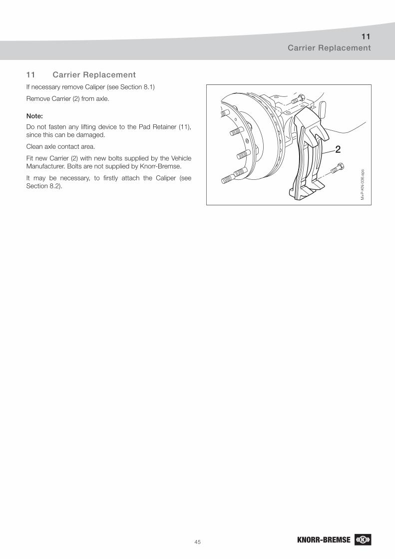
45
Carrier Replacement11
M+
P-K
N-0
36.e
ps
2
If necessary remove Caliper (see Section 8.1)
Remove Carrier (2) from axle.
Note:
Do not fasten any lifting device to the Pad Retainer (11),
since this can be damaged.
Clean axle contact area.
Fit new Carrier (2) with new bolts supplied by the Vehicle
Manufacturer. Bolts are not supplied by Knorr-Bremse.
It may be necessary, to fi rstly attach the Caliper (see
Section 8.2).
11 Carrier Replacement
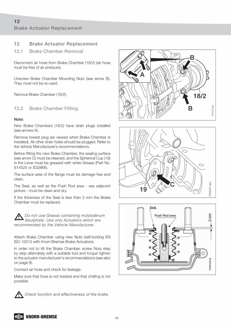
46
Brake Actuator Replacement12
FD
00
22
9.e
ps
18/2
A
B
B
FD
00231.e
psC
19
3 m
mPush Rod area
Seal
12.1 Brake Chamber Removal
Disconnect air hose from Brake Chamber (18/2) (air hose
must be free of air pressure).
Unscrew Brake Chamber Mounting Nuts (see arrow B).
They must not be re-used.
Remove Brake Chamber (18/2).
12.2 Brake Chamber Fitting
Note:
New Brake Chambers (18/2) have drain plugs installed
(see arrows A).
Remove lowest plug (as viewed when Brake Chamber is
installed). All other drain holes should be plugged. Refer to
the Vehicle Manufacturer’s recommendations.
Before fi tting the new Brake Chamber, the sealing surface
(see arrow C) must be cleaned, and the Spherical Cup (19)
in the Lever must be greased with white Grease (Part No.
II14525 or II32868).
The surface area of the fl ange must be damage free and
clean.
The Seal, as well as the Push Rod area - see adjacent
picture - must be clean and dry.
If the thickness of the Seal is less than 3 mm the Brake
Chamber must be replaced.
Do not use Grease containing molybdenum
disulphate. Use only Actuators which are
recommended by the Vehicle Manufacturer.
Attach Brake Chamber using new Nuts (self-locking EN
ISO 10513 with Knorr-Bremse Brake Actuators).
In order not to tilt the Brake Chamber, screw Nuts step
by step alternately with a suitable tool and torque tighten
to the actuator manufacturer‘s recommendations (see also
on page 9).
Connect air hose and check for leakage.
Make sure that hose is not twisted and that chafi ng is not
possible.
Check function and effectiveness of the brake.
12 Brake Actuator Replacement
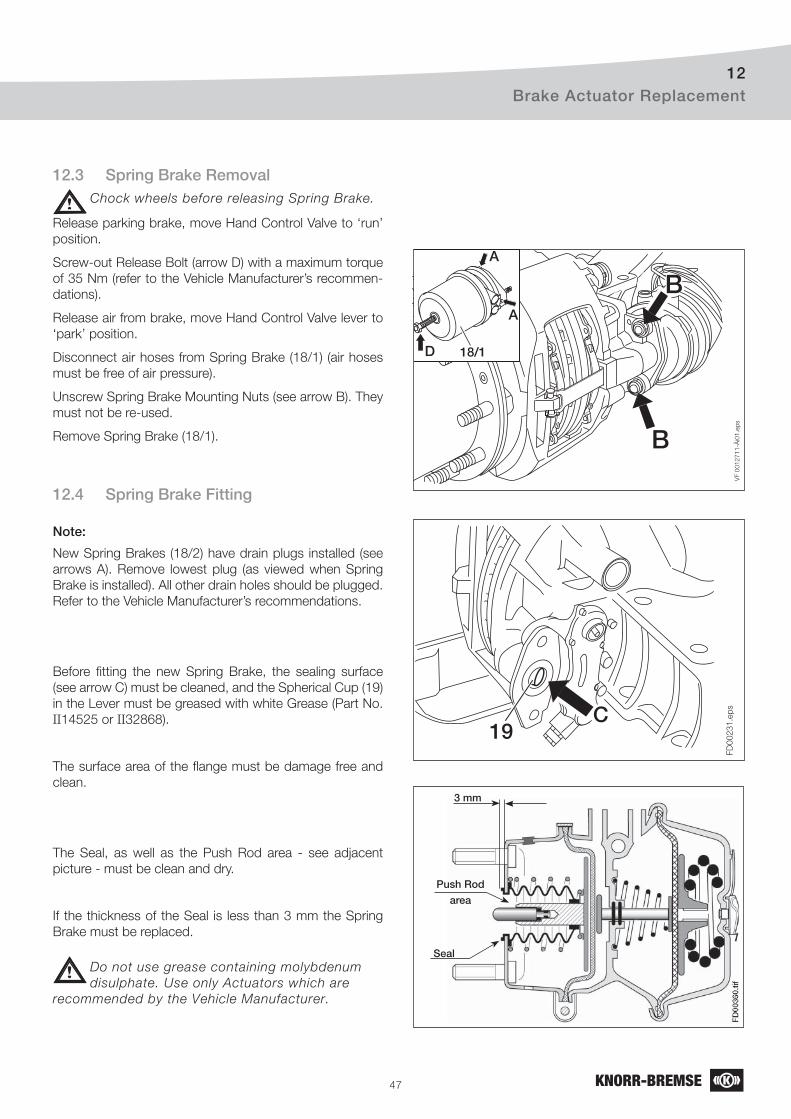
47
Brake Actuator Replacement12
VF 0
012711-Ä
i01.e
ps
B
BA
A
D 18/1
FD
00231.e
psC
19
3 mm
Push Rod
area
Seal
12.3 Spring Brake RemovalChock wheels before releasing Spring Brake.
Release parking brake, move Hand Control Valve to ‘run’
position.
Screw-out Release Bolt (arrow D) with a maximum torque
of 35 Nm (refer to the Vehicle Manufacturer’s recommen-
dations).
Release air from brake, move Hand Control Valve lever to
‘park’ position.
Disconnect air hoses from Spring Brake (18/1) (air hoses
must be free of air pressure).
Unscrew Spring Brake Mounting Nuts (see arrow B). They
must not be re-used.
Remove Spring Brake (18/1).
12.4 Spring Brake Fitting
Note:
New Spring Brakes (18/2) have drain plugs installed (see
arrows A). Remove lowest plug (as viewed when Spring
Brake is installed). All other drain holes should be plugged.
Refer to the Vehicle Manufacturer’s recommendations.
Before fi tting the new Spring Brake, the sealing surface
(see arrow C) must be cleaned, and the Spherical Cup (19)
in the Lever must be greased with white Grease (Part No.
II14525 or II32868).
The surface area of the fl ange must be damage free and
clean.
The Seal, as well as the Push Rod area - see adjacent
picture - must be clean and dry.
If the thickness of the Seal is less than 3 mm the Spring
Brake must be replaced.
Do not use grease containing molybdenum
disulphate. Use only Actuators which are
recommended by the Vehicle Manufacturer.
48
Brake Actuator Replacement12
Attach Spring Brake using new Nuts (self-locking EN ISO
10513 with Knorr-Bremse Brake Actuators).
In order not to tilt the Brake Chamber, screw Nuts step
by step alternately with a suitable tool and torque tighten
to the actuator manufacturer‘s recommendations (see also
on page 9).
Connect air hoses, ensuring that they are replaced in the
correct ports.
Make sure that hoses are not twisted and that chafi ng is
not possible.
Release parking brake, move Hand Control Valve lever to
‘run’ position, and check for leakage.
Screw in Spring Brake Release bolt to maximum 70 Nm.
Check function and effectiveness of the brake.

49
Notes

50
Notes

51
Notes
C o m m e r c i a l V e h i c l e S y s t e m s
JapanKnorr-Bremse Commercial Vehicle Systems Japan Ltd.TokyoTel: +81 3 3971-8501Fax: +81 3 3971-8579
Korea Knorr-Bremse Korea Ltd. Truck Brake DivisionSeoul Tel: +82 2 2273-1182Fax: +82 2 2273-1184
Netherlands Knorr-Bremse Benelux B.V.B.A.Mydrecht Tel: +31 297 239-330Fax: +31 297 239-339
PolandKnorr-Bremse Polska SfN Sp. z o.o.WarsawTel: +48 22 887 3870Fax: +48 22 887 3860
RussiaKnorr-Bremse RUS Nizhniy NovgorodTel: +7 8312 57-6661Fax: +7 8312 57-6791
Knorr-BremseSysteme für Nutzfahrzeuge GmbHMoscowTel: +7 495 234-4995Fax: +7 495 234-4996
South Africa Knorr-Bremse S.A. Pty. Ltd. Kempton Park Tel: +27 11 961-7800Fax: +27 11 975-8249
SpainBOST IBERICA, S.L.Irun (Guipuzcoa) Tel: +34 902 100 569Fax: +34 943 614 063
Sweden Knorr-BremseSystem for Tunga Fordon ABMalmoeTel: +46 40 680 5880Fax: +46 40 937490
SwitzerlandKnorr-BremseSysteme für Nutzfahrzeuge GmbHBassersdorf Tel: +41 44 888 77-55Fax: +41 44 888 77-50
Turkey Knorr-BremseSysteme für Nutzfahrzeuge GmbHFindikli - IstanbulTel: +90 212 293-4742Fax: +90 212 293-4743
United Kingdom Knorr-Bremse Systems for Commercial Vehicles Ltd.BristolTel: +44 117 9846-100Fax: +44 117 9846-101
USABendix Commercial Vehicle Systems LLC Elyria, OH Tel: +1 440 329-9100Fax: +1 440 329-9105
Knorr-Bremse Systeme für Nutzfahrzeuge GmbH Moosacher Straße 80
80809 Munich
Germany
Tel: +49 89 3547-0
Fax: +49 89 3547-2767
www.knorr-bremsesfn.com
Copy
right
2006
© Kn
orr-B
remse
AG -
all rig
hts re
serve
d, inc
luding
indu
strial
prop
erty r
ights
appli
catio
ns. K
norr-
Brems
e AG r
etains
any p
ower
of dis
posa
l, suc
h as f
or co
pying
and t
ransfe
rring
. Prin
ted in
Germ
any.
AustraliaKnorr-Bremse Australia Pty. Ltd. Granville NSWTel: +61 2 8863-6500Fax: +61 2 8863-6151
Austria Knorr-Bremse GmbHSysteme für NutzfahrzeugeMödlingTel: +43 2236 409-436Fax: +43 2236 409-434
BelgiumKnorr-Bremse Benelux B.V.B.A.Heist-op-den-BergTel: +32 1525 7900Fax: +32 1524 9240
Brazil Knorr-BremseSistemas para Veículos Comerciais Brasil Ltda.São Paulo Tel: +55 11 5681 1104Fax: +55 11 5686 3905
China Knorr-Bremse Brake Equipment (Shanghai) Co. Ltd. Truck Brake Systems DivisionShanghaiTel: +86 21 6891-7525Fax: +86 21 6891-7510
Knorr-Bremse Far East Ltd.Truck Brake Systems DivisionHong Kong Tel: +852 2861 2669Fax: +852 2520 6259
Czech RepublicKnorr-Bremse Systémy pro uzitková vozidla, CR, s.r.o.HejniceTel: +420 482 363-611Fax: +420 482 363-711
France Knorr-Bremse Systèmes pour Véhicules Utilitaires France S.A.Lisieux CedexTel: +33 2 3132 1200Fax: +33 2 3132 1303
Germany Hasse & Wrede GmbH Berlin Tel: +49 30 9392-3101Fax: +49 30 7009-0811
HungaryKnorr-Bremse Fékrendszerek Kft.Kecskemét Tel: +36 76 511 100Fax: +36 76 481 100
IndiaKnorr-BremseSystems for Commercial Vehicles India Private Ltd.PuneTel: +91 20 2293-9141-47Fax: +91 20 2293-9148
ItalyKnorr-Bremse Sistemi per Autoveicoli Commerciali S.p.A.Arcore Tel: +39 039 6075-1Fax: +39 039 6075-435
Refe
rence N
o.: K
001262-0
02
Doc. N
o.: Y
006471-E
N-0
02
������������������������������������������������
��������������������������������������������� ���������������
��������������������������������� �����������������������������������������

SSEERRVVIICCEE MMAANNUUAALL GGeenneerraall IInnffoorrmmaattiioonn
Service Manual 613505 2
� ��������������� ���� ������������ ���� ������ ��������� ������������
��������� ����� ��� ������� ����� �� ����� �����
���������� ����� ��� ������� ����� � ����� �������
���������� ������ ��� ������� ������ �� ����� �������
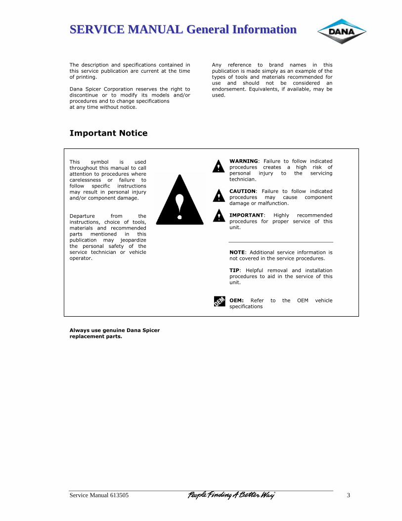
SSEERRVVIICCEE MMAANNUUAALL GGeenneerraall IInnffoorrmmaattiioonn
Service Manual 613505 3
������������� ���!��!��� ���"������!����!���!����!���������#���� $%�������!������$���!�����������&���"� ��!��!'����(�!��) ����� ��� ������!������#���������'�����������!��!$�� ��� ��� &���"*� ���� &������ �!�+��� �����$�����!��������!'��� ���"������!������!*���&��,����$��!����������
������������������������ �*&%��� ��� $��������$'��$�������&�!$���������������!���!���� �����$����,�������������!���� ��� "���$��� ���"����,� � ���"��� �!���$����!��&�*����$����!� ����!��� �!-$�*��!�+�����& �!�!����&�'�����(� ���$��� "��&� �����!���$����!�.� ������� �"� �����.�&��������� �!�� ����&&�!���� ����� &�!���!��� �!� ����� $%�������!� &�*� -�� ����/������ ����!��� ��"��*� �"� �������#���� ����!����!� ��� #�������� ������������
����
���������� ������ ��� ����!�����
����������������������
����!*� ��"���!��� ��� %��!�� !�&��� �!� ����� $%�������!����&������& �*�����!��0�& ����"������* ����"��������!��&�������������&&�!����"���$��� �!�� ���$��� !��� %�� ��!�������� �!��!�����&�!���12$�#���!��.��"��#����%��.�&�*�%��$���������������
"�����#3� 4���$��� ��� "����,� �!�������� �����$���� �������� �� ��'�� ���5� �"� ����!��� �!-$�*� ��� ���� ���#���!'�����!����!�����$%�&�3� 4���$��� ��� "����,� �!�������� �����$���� &�*� ��$��� ��& �!�!����&�'�����&��"$!����!�����'&�%��%3� 6�'��*� ����&&�!���� �����$���� "��� �� ��� ���#���� �"� �����$!������
��&%�3� �������!������#�����!"��&����!����!�����#������!��������#���� �����$������%�'3� 6�� "$�� ��&�#��� �!�� �!���������!� �����$������������!��������#���� �"������$!������&��(� 7�"��� ��� ���� �1�� #�������� ���"������!��
����
SSEERRVVIICCEE MMAANNUUAALL GGeenneerraall IInnffoorrmmaattiioonn
Service Manual 613505 4
##������������������))&&������%%��&&�������� ��**���
++������,,�����������������������������0���6�$��!'�8��!��"������!99999999999999999999999999999999999999999�� ���0���:�(��#��6����8��!��"������!99999999999999999999999999999999999999�� ��7�!'�;����:�<�!��!�8��!��"������!9999999999999999999999999999999999999� ���
--������ ����������������� ��#���=$%����!��999999999999999999999999999999999999999999999�� ����������*+�&%��!����& ����$���7���&&�!�����!�99999999999999999999999999��� ��=$%�����!'��8!���#���99999999999999999999999999999999999999999999� �����!'�!'�=$%�999999999999999999999999999999999999999999999999�� ��>�����1!��=$%�������!99999999999999999999999999999999999999999999� ���
..������������������������4���$����!��*���999999999999999999999999999999999999999999999999� ?�6�,�������'!������4���$��99999999999999999999999999999999999999999��� ?�<�� �������� �����"����!� �����!99999999999999999999999999999999999999�� �4�!��������$����"�����"���$��9999999999999999999999999999999999999999�� ���������������$����"����� ��%��&9999999999999999999999999999999999999� �8!� �����!999999999999999999999999999999999999999999999999999�� ��
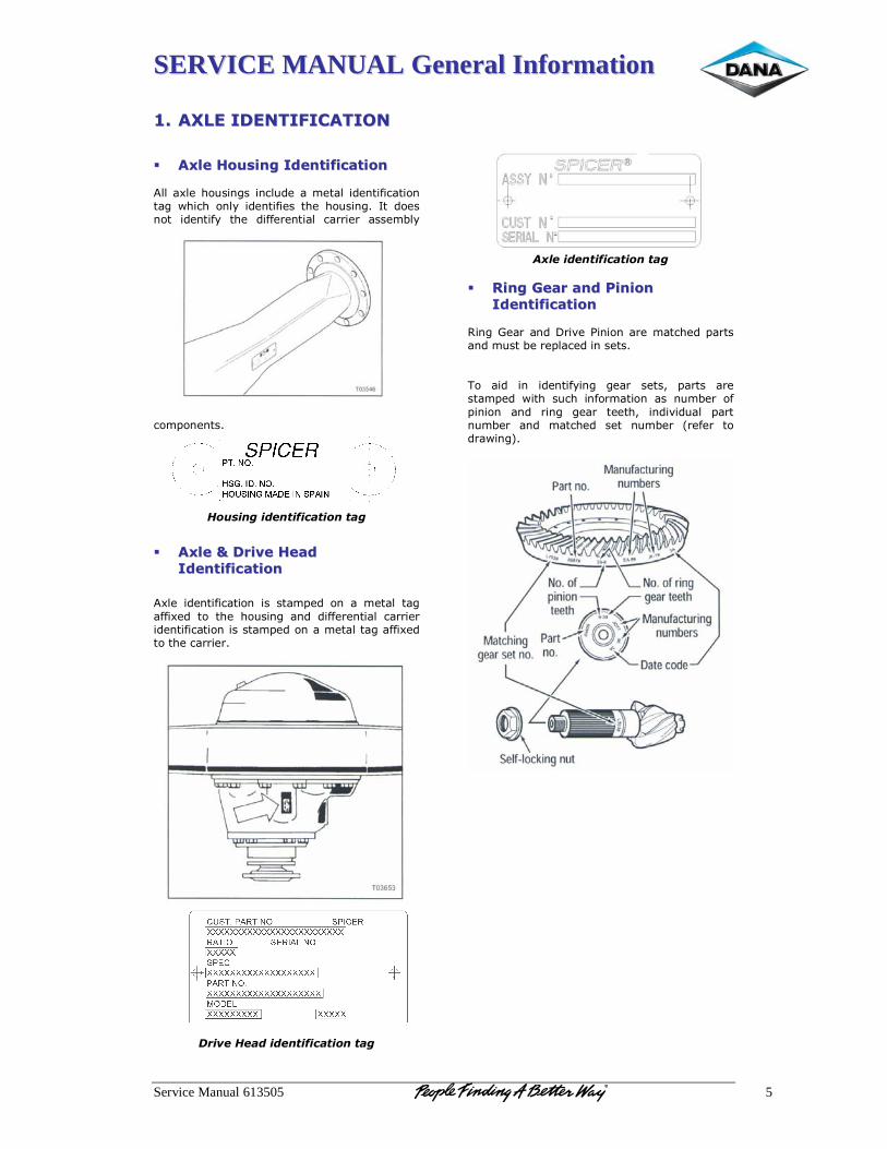
SSEERRVVIICCEE MMAANNUUAALL GGeenneerraall IInnffoorrmmaattiioonn
Service Manual 613505 5
++�� ��**�������� ����%%��))������%%��&&������
�� ��,,������//�� ������������������������������������0�����$��!'���!��$�����&��������!��"������!���'� ,����� �!�*����!��"�������� ��$��!'�� 8�� �����!��� ���!��"*� ���� ��""���!����� �������� ����&%�*�
��& �!�!����
��������������� ����������
��� ��,,������00�� ��������//��������
����������������������
��0��� ���!��"������!� ��� ���& ��� �!� �� &����� ��'��""�0��� ��� ���� ��$��!'� �!�� ��""���!����� �����������!��"������!�������& ����!���&�������'��""�0��������������������
���������
��
�������������� ����������
���
����������� ����������
�
�� ��������##����������������''��������
�����������������������7�!'�;�����!��(��#��<�!��!�����&������� ������!��&$���%���� �������!������������� ���� �!� ���!��"*�!'� '���� ����.� ����� �������& ��� ,���� �$��� �!"��&����!� ��� !$&%��� �"� �!��!� �!�� ��!'� '���� �����.� �!��#��$��� ����!$&%��� �!�� &������� ���� !$&%��� @��"��� ������,�!'A���
���
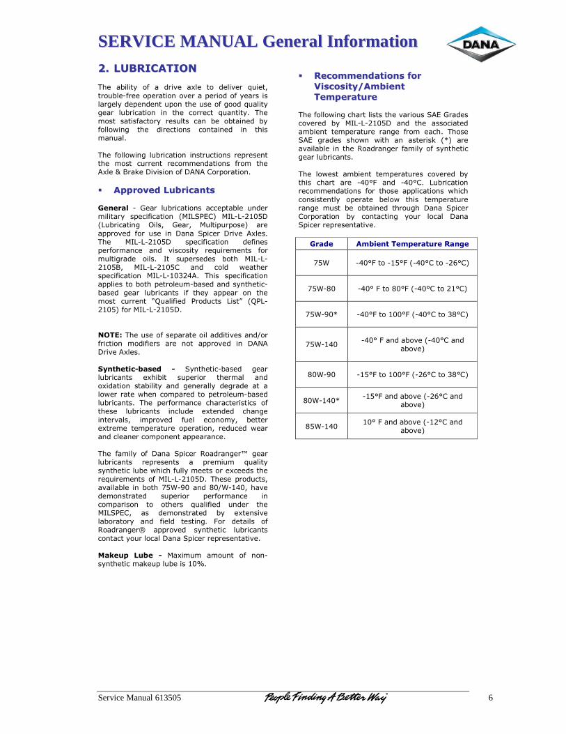
SSEERRVVIICCEE MMAANNUUAALL GGeenneerraall IInnffoorrmmaattiioonn
Service Manual 613505 6
--�� ��$$11��������%%��&&��������� �%����*� �"� �� ���#�� �0��� ��� ����#��� 2$���.����$%��B"����� ������!��#����� �������"�*�����������'��*��� �!��!��$ �!�����$����"�'����2$����*�'���� �$%�������!� �!� ���� �������� 2$�!���*�� ����&���� �����"�����*� ���$���� ��!� %�� �%���!��� %*�"����,�!'� ���� ��������!�� ��!���!��� �!� �����&�!$���������"����,�!'��$%�������!��!���$����!���� ����!������ &���� �$���!�� ����&&�!�����!�� "��&� �����0���:� ��5��(�#����!��"�(������� ������!���
�� �������������������� �����������������#������� B� ;���� �$%�������!�� ���� ��%��� $!����&������*� � ���"������!� @�8=)<1�A� �8=B=B��(�@=$%������!'� ����.� ;���.� �$��� $� ���A� ����� ��#��� "��� $����!�(�!�� ) �����(��#�� �0��������� �8=B=B��(� � ���"������!� ��"�!��� ��"��&�!��� �!�� #�������*� ��2$���&�!��� "���&$���'����� ������ 8�� �$ �������� %���� �8=B=B�� .� �8=B=B���� �!�� ����� ,�������� ���"������!� �8=B=B������ ����� � ���"������!�� ��������%���� ������$&B%������!���*!������B%����� '���� �$%����!��� �"� ���*� � ���� �!� ����&���� �$���!�� CD$���"���� <���$���� =���E� @D<=B��A�"����8=B=B��(�����&%�(�����$����"��� ����������������#����!�+���"������!� &���"����� ���� !��� � ��#��� �!� (����(��#���0������!�������2������ 2� )*!������B%����� '�����$%����!��� �0��%��� �$ ������ ����&��� �!���0������!� ���%����*� �!�� '�!�����*� ��'����� ��� ����,��������,��!���& �������� ������$&B%������$%����!���� ���� ��"��&�!��� ���������������� �"������� �$%����!��� �!��$��� �0��!���� ���!'���!���#���.� �& ��#��� "$��� ���!�&*.� %�������0���&����& ����$��� � ������!.����$���� ,�����!������!�����& �!�!��� ����!��������� "�&��*� �"� (�!�� ) ����� 7�����!'��F� '�����$%����!��� �� ����!��� �� ��&�$&� 2$����*��*!��������$%��,�����"$��*�&���������0������������2$���&�!����"��8=B=B��(�������� ���$���.��#����%����!�%������>B?��!���+>B�.���#����&�!�������� �$ ������ ��"��&�!��� �!���& �����!� ��� ������� 2$���"���� $!���� �����8=)<1�.� ��� ��&�!�������� %*� �0��!��#����%������*� �!�� "����� �����!'�� 4��� �������� �"�7�����!'��G� � ��#��� �*!������� �$%����!�����!�����*�$��������(�!��) ������� ����!����#�������3� �� � ��� 2� ��0�&$&� �&�$!�� �"� !�!B�*!�������&�5�$ ��$%�����H�����
�
�� ������������������������������������
44������������55��������������
%%�������������� �����������"����,�!'�����������������#����$��)�1�;��������#����� %*� �8=B=B��(� �!�� ���� ������������&%��!�� ��& ����$��� ��!'�� "��&� ������ ������)�1� '������ ���,!� ,���� �!� �������5� @IA� �����#����%����!�����7�����!'���"�&��*��"��*!�������'�����$%����!��������� ��,���� �&%��!�� ��& ����$���� ��#����� %*������ ������ ���� B�J4� �!�� B�J��� =$%�������!�����&&�!�����!�� "��� ������� �������!��,�������!�����!��*� � ������ %���,� ����� ��& ����$�����!'�� &$��� %�� �%���!��� ����$'�� (�!�� ) �������� ������!� %*� ��!�����!'� *�$�� ������ (�!��) ������� ����!����#����
#����� �������%������� ���������
��>��
B�J4����B�J4�@B�J�����B��J�A��
���>B���
�B�J�4�����J4�@B�J������J�A�
�
��>B?I��
B�J4����J4�@B�J�������J�A��
��>B��
�B�J�4��!���%�#��@B�J���!��
�%�#�A��
��>B?��
B�J4����J4�@B��J�������J�A�
��>B�I�
�
B�J4��!���%�#��@B��J���!���%�#�A�
���>B��
�
J�4��!���%�#��@B�J���!���%�#�A�
�����������
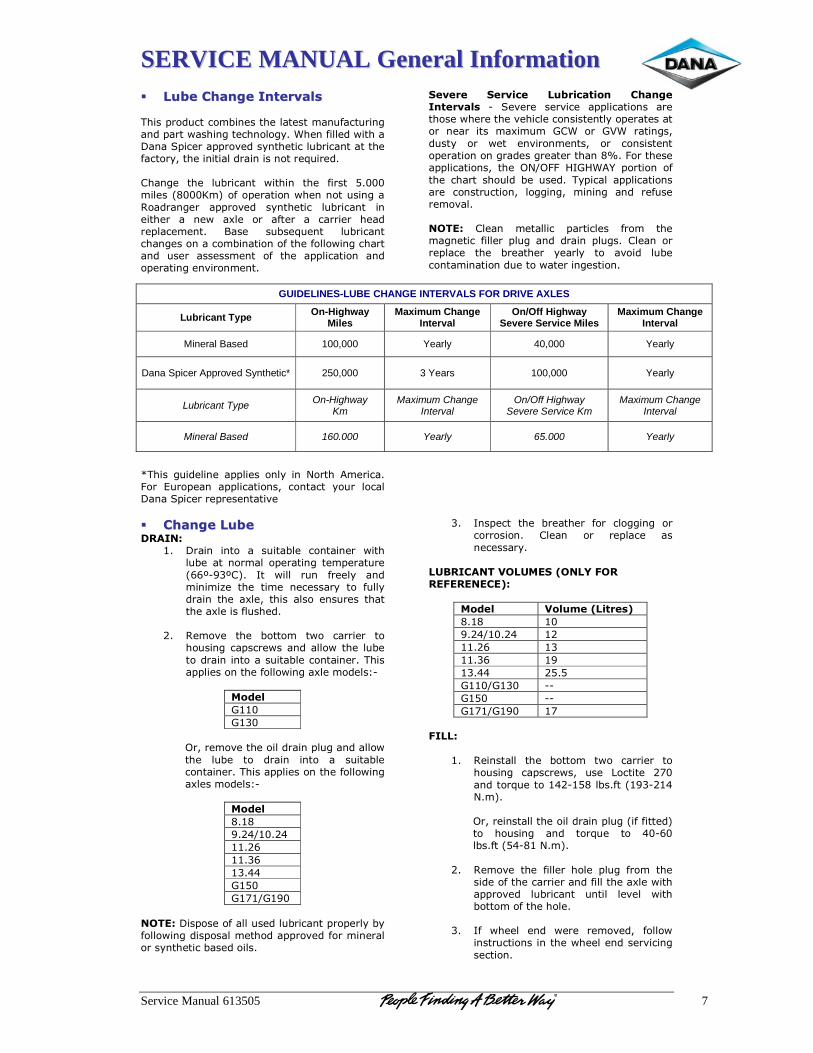
SSEERRVVIICCEE MMAANNUUAALL GGeenneerraall IInnffoorrmmaattiioonn
Service Manual 613505 7
�� �� ���������������������������������������������� ���$�����&%�!��������������&�!$"���$��!'��!�� ����,����!'�����!���'*��>��!�"������,������(�!��) ������ ��#����*!��������$%����!���������"�����*.������!����������!����!�����2$����������!'�� ���� �$%����!�� ,����!� ���� "����� ���&�����@�K&A��"�� ������!�,��!�!���$��!'���7�����!'��� � ��#��� �*!������� �$%����!�� �!�������� �� !�,� �0��� ��� �"���� �� �������� ������� ����&�!��� ���� �$%��2$�!�� �$%����!�����!'����!�����&%�!����!��"�����"����,�!'��������!�� $���� ������&�!�� �"� ���� � �������!� �!��� �����!'��!#���!&�!�������������������I�����'$�����!��� ����� �!�*��!������� �&�������4��� 1$�� ��!� � �������!�.� ��!����� *�$�� ������(�!��) ������� ����!����#���
!������ !������ � �������� ����������������� B� )�#���� ���#���� � �������!�� ����������,���������#���������!�����!��*�� ������������� !���� ���� &�0�&$&� ;�>� ��� ;�>� ����!'�.��$��*� ��� ,��� �!#���!&�!��.� ��� ��!�����!��� ������!��!�'������'����������!��H��4���������� �������!�.� ������+�44� 68;6>�L� �����!� �"��������������$���%�� $����� �* ������ �������!������ ��!���$����!.� ��''�!'.� &�!�!'� �!�� ��"$�����&�#������&%�(� ����!� &�������� ��������� "��&� ����&�'!�����"������ �$'��!�� ����!� �$'��� ����!� ����� ����� ���� %�������� *����*� ��� �#���� �$%����!��&�!����!��$�����,������!'�����!�������������������
�� ���������������� ������ ����(�
� (���!� �!��� �� �$���%��� ��!���!��� ,�����$%�����!��&���� �����!'���& ����$���@��MB?�M�A�� 8�� ,���� �$!� "����*� �!��&�!�&�/�� ���� ��&�� !�������*� ��� "$��*�����!������0��.����������� �!�$��������������0������"�$������
��� 7�&�#�� ���� %����&� �,�� �������� ���
��$��!'��� ����,���!������,������$%���������!��!������$���%�����!���!���������� ������!�����"����,�!'��0���&�����3B�
�������
;�;��
�� ��.���&�#��������������!� �$'��!������,�� ���� �$%�� ��� ����!� �!��� �� �$���%���� ��!���!���������� ������!�����"����,�!'�� �0����&�����3B��
������
����?���+�����������������;��;�+;?�
��&%�(�(�� �����"�����$�����$%����!�� �� ���*�%*�"����,�!'���� �����&������� ��#���"���&�!���������*!�������%�����������
�� 8!� ���� ���� %�������� "��� ���''�!'� �����������!�� ����!� ��� �� ����� ���!�������*��
��$1�����%�4&�$��!�6&��7�)&����)�������8(��
������ 4�� ���6�����8�
���� �?���+���� ������ ������ ?������ �����;+;�� BB�;�� BB�;�+;?� ��
�)���(�
�� 7��!������ ���� %����&� �,�� �������� ���
��$��!'� �� ����,�.� $��� =������� ����!�����2$�������B����%��"��@?�B�����&A��
�� ��.����!������������������!� �$'�@�"�"�����A�� ��� ��$��!'� �!�� ���2$�� ��� �B��� �%��"��@��B����&A����� 7�&�#�� ���� "������ ����� �$'� "��&� ����
������"��������������!��"���������0���,����� ��#��� �$%����!�� $!���� ��#��� ,����%����&��"�����������
��� 8"� ,����� �!�� ,���� ��&�#��.� "����,�
�!���$����!���!�����,������!�����#���!'�������!��
GUIDELINES-LUBE CHANGE INTERVALS FOR DRIVE AXLES
Lubricant Type On-Highway Miles
Maximum Change Interval
On/Off Highway Severe Service Miles
Maximum Change Interval
Mineral Based 100,000 Yearly 40,000 Yearly
Dana Spicer Approved Synthetic* 250,000 3 Years 100,000 Yearly
Lubricant Type On-Highway Km
Maximum Change Interval
On/Off Highway Severe Service Km
Maximum Change Interval
Mineral Based 160.000 Yearly 65.000 Yearly
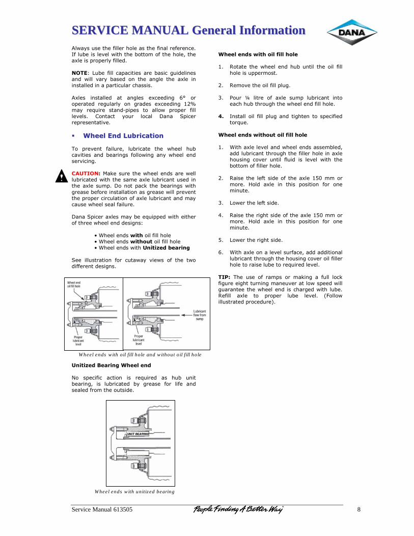
SSEERRVVIICCEE MMAANNUUAALL GGeenneerraall IInnffoorrmmaattiioonn
Service Manual 613505 8
��,�*��$�������"������������������"�!�����"���!����8"��$%�������#���,��������%����&��"���������.������0������ �� ���*�"���������&%�3� =$%��"������ ������������%�����'$�����!����!�� ,���� #��*� %����� �!� ���� �!'������� �0��� �!��!���������!��� �����$���������������0���� �!�������� ��� �!'���� �0�����!'� �J� ���� ������� ��'$����*� �!� '������ �0�����!'� �H�&�*� ��2$���� ���!�B � ��� ��� ����,� �� ��� "������#����� ��!����� *�$�� ������ (�!�� ) ������� ����!����#����
�� ""�������������������� �����������������
��� ��#�!�� "���$��.� �$%������� ���� ,����� �$%���#�������!��%����!'��"����,�!'��!*�,������!�����#���!'�����$%�&�(���5���$�������,������!�������,�����$%��������,����������&���0����$%����!��$�����!������0����$& ��(��!��� ��5�����%����!'��,����'������%�"�����!���������!����'������,���� ��#�!������ �� �������$�����!��"��0����$%����!���!��&�*���$���,����������"���$�����(�!��) ������0����&�*�%���2$� ���,������������"�������,������!������'!�3��
N�>������!�����������"���������N�>������!������� ������"���������
� N�>������!���,����$��9�����������)��� ���$�������!� "��� �$��,�*� #��,�� �"� ���� �,����""���!������'!������������������$��9���1������"����������
���� � ���"��� �����!� ��� ��2$����� ��� �$%� $!���%����!'.� ��� �$%�������� %*� '������ "��� ��"�� �!���������"��&������$���������
�
���������������
�"��������������������������� 7����������,������!���$%� $!�������� ����"����
��������$ ��&�������� 7�&�#����������"���� �$'����� <�$�� O� ������ �"� �0��� �$& � �$%����!�� �!���
������$%�����$'������,������!��"�����������:� 8!����������"���� �$'��!����'���!����� ���"����
���2$�����
"�������������� ��������������� >�����0�����#����!��,������!�������&%���.�
�����$%����!������$'������"������������!��0�����$��!'���#��� $!���� "�$��� �����#���,��������%����&��"�"������������
��� 7�����������"��������"������0�����&&����
&����� 6���� �0��� �!� ����� ������!� "��� �!��&�!$����
��� =�,���������"����������� 7�����������'���������"������0�����&&����
&����� 6���� �0��� �!� ����� ������!� "��� �!��&�!$����
��� =�,���������'������������ >�����0����!�����#����$�"���.������������!���
�$%����!������$'��������$��!'���#�������"���������������������$%�������2$�������#����
�%�'(����� $��� �"� ��& �� ��� &�5�!'���"$��� ���5�"�'$�����'����$�!�!'�&�!�$#��������,�� ����,����'$���!��������,������!���������'���,�����$%���7�"���� �0��� ��� �� ��� �$%�� ��#���� @4����,����$�������� �����$��A������
Wheel ends with unitized bearing
Wheel ends with oil fill hole and without oil fill hole
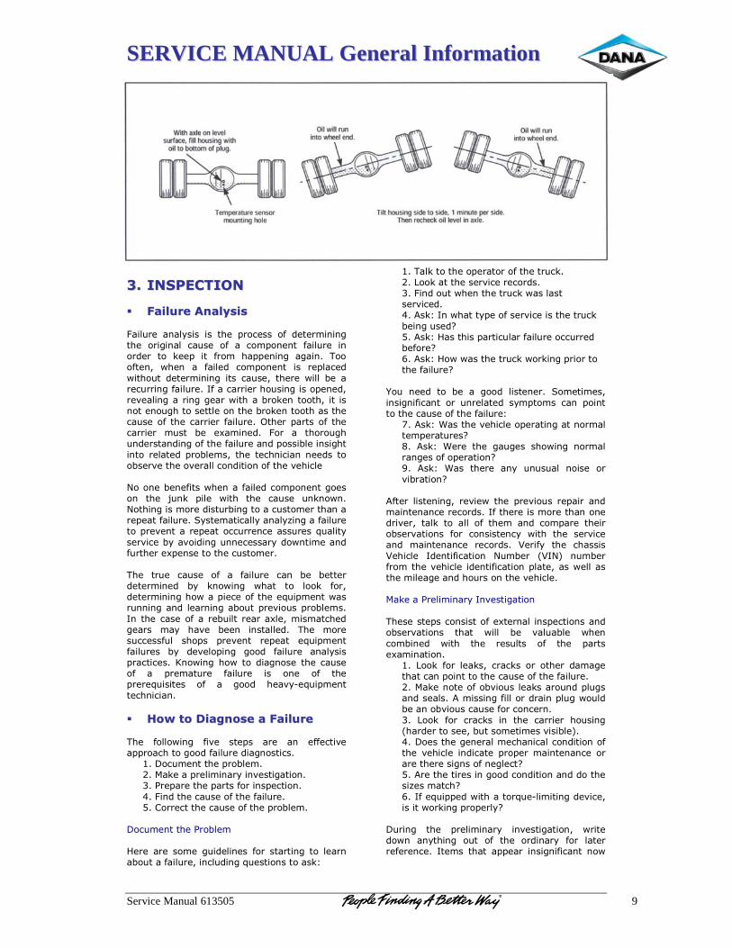
SSEERRVVIICCEE MMAANNUUAALL GGeenneerraall IInnffoorrmmaattiioonn
Service Manual 613505 9
������������������
..�� ����!!''����%%��&&�����
�� ))���� �����������������������4���$��� �!��*���� ��� ���� ������� �"� �����&�!�!'����� ���'�!��� ��$��� �"� �� ��& �!�!�� "���$��� �!������� ��� 5�� � ��� "��&� �� �!�!'� �'��!�� �����"��!.� ,��!� �� "������ ��& �!�!�� ��� �� ������,����$�� �����&�!�!'�������$��.�������,����%�������$���!'�"���$����8"�������������$��!'����� �!��.���#����!'�����!'�'����,������%��5�!������.�������!����!�$'�������������!�����%��5�!����������������$����"�������������"���$���������� ������"������������� &$��� %�� �0�&�!���� 4��� �� �����$'��$!������!��!'��"�����"���$����!�� ����%����!��'����!����������� ��%��&�.���������!����!�!���������%���#�������#��������!�����!��"�����#������������!��%�!�"����,��!���"��������& �!�!��'�����!� ���� -$!5� ���� ,���� ���� ��$��� $!5!�,!�������!'����&��������$�%�!'�������$���&������!����� ����"���$����)*���&�������*��!��*/�!'���"���$������ ��#�!������ �������$���!������$����2$����*����#����%*��#����!'�$!!�������*���,!��&���!��"$�������0 �!�����������$���&��������� ��$�� ��$��� �"� �� "���$��� ��!� %�� %�����������&�!��� %*� 5!�,�!'� ,���� ��� ���5� "��.������&�!�!'���,��� ������"������2$� &�!��,����$!!�!'��!������!�!'��%�$�� ��#��$�� ��%��&���8!�����������"�����%$����������0��.�&��&�������'����� &�*� ��#�� %��!� �!��������� ���� &�����$�����"$�� ��� �� ��#�!�� �� ���� �2$� &�!��"���$���� %*� ��#��� �!'� '���� "���$��� �!��*���� ����������K!�,�!'���,���� ���'!����������$����"� �� ��&��$��� "���$��� ��� �!�� �"� ���� ����2$������� �"� �� '���� ���#*B�2$� &�!������!����!���
�� //������������ ������������������))���� ����������� "����,�!'� "�#�� ��� �� ���� �!� �""����#��� ���������'����"���$������'!����������(��$&�!������ ��%��&�������5���� ����&�!��*��!#����'����!�����<�� �������� �����"����!� �����!�����4�!��������$����"�����"���$���������������������$����"����� ��%��&��
�(��$&�!������<��%��&��6����������&��'$�����!���"���������!'��������!��%�$����"���$��.��!��$��!'�2$�����!�������53�
�����5��������� ��������"�������$�5�����=��5�����������#����������������4�!���$��,��!�������$�5�,�����������#�����������53�8!�,�����* ���"����#�������������$�5�%��!'�$���P������53�6�������� �����$����"���$������$�����%�"���P������53�6�,�,���������$�5�,��5�!'� ������������"���$��P��
L�$� !���� ��� %�� �� '���� �����!���� )�&���&��.��!��'!�"���!�� ��� $!�������� �*& ��&�� ��!� ��!�����������$����"�����"���$��3������53�>�������#�������� �����!'����!��&�����& ����$���P���� ��53� >���� ���� '�$'��� ���,�!'� !��&�����!'����"�� ������!P�?�� ��53� >��� ������ �!*� $!$�$��� !����� ���#�%�����!P�
��"���������!�!'.���#��,����� ��#��$���� �����!��&��!��!�!������������8"����������&�������!��!�����#��.� ���5� ��� ���� �"� ���&� �!�� ��& ���� �������%���#����!�� "��� ��!�����!�*� ,���� ���� ���#�����!�� &��!��!�!��� ��������� ����"*� ���� ���������������� 8��!��"������!� �$&%��� @�8�A� !$&%���"��&�����#����������!��"������!� ����.����,�����������&����'���!����$����!�����#�����������5����<����&�!��*�8!#����'����!����������� ����!������"��0���!����!� �����!���!���%���#����!�� ����� ,���� %�� #��$�%��� ,��!���&%�!��� ,���� ���� ���$���� �"� ���� ������0�&�!����!���� =��5�"������5�.�����5�� ��� ������ ��&�'���������!� ��!�����������$����"�����"���$���������5��!�����"��%#��$�����5�����$!�� �$'���!�����������&����!'�"�����������!� �$'�,�$���%���!��%#��$����$���"�����!���!����� =��5� "��� ����5�� �!� ���� �������� ��$��!'�@�������������.�%$����&���&���#���%��A�����(��������'�!�����&����!�������!�����!��"�����#��������!������� �� ���&��!��!�!��� ���������������'!���"�!�'����P�������������������!�'������!�����!��!�����������/���&����P����8"��2$� ���,���������2$�B��&���!'���#���.�������,��5�!'� �� ���*P�
�($��!'� ���� ����&�!��*� �!#����'����!.� ,�������,!� �!*���!'� �$�� �"� ���� ����!��*� "��� ��������"���!����8��&�������� �����!��'!�"���!��!�,�
SSEERRVVIICCEE MMAANNUUAALL GGeenneerraall IInnffoorrmmaattiioonn
Service Manual 613505 10
&�*� ��5�� �!� &���� �& ����!��� ,��!� �����$%����&%������������!���,!���
�� ''����������������������''����������������
����������������������"���� ���� ����&�!��*� �!#����'����!.� ������� ����"���$����!�� �� �������� ����"����0�&�!����!��8!���������"���$����!��*���.����&�*�%��!�������*�����������&%�������$!������ >��!� �������&%��!'� �$%����&%����� �!�� ����.� ��� !��� ����!� ���� ����� �&&�������*���!��� ����!�!'� &�*� ������*� ��&�� �"� �����#���!�������>��!������!'���,!��������#���0��.��������!���������&&�!����&�!!������!�&�/���!*�"$��������&�'���������$!���������5�&����2$�����!��,��!��0�&�!�!'������!������� �"� ���� ��������� (���� ���� �$%����!��&���� ���� &�!$"���$���� � ���"������!����'����!'�2$����*.�2$�!���*��!��#�������*P�������!� ��� *�$� ��#�� �������� ���� "������ ���.���5����&������!��*/������������
�
�� ))������������������ ������������������))���� �������6����%�'�!�����������������!'����������&�!�������0������$��� �"� ����"���$���� K�� ��!�&�!�� ����������� ��� !�� %�!�"��� ��� �� ����!'� �� "������ ����,����$�� �����&�!�!'� ���� ��$��� �"� ���� "���$����4����0�& ��.��"�����0�&�!�!'���"������ �����!��"�!��!'����������"���$��������$����%*������5� �"��$%�������!.�*�$�&$��������&�!���"�������,����!��0���!������5���%#��$��*.��"�����������!��0���!������5.�-$����� ����!'�����"������'�������!���'��!'�������������������$����!����!�������& ����!����!���������!������������&�!������ � ���"��� �* �� �"� "���$��� ,����� ��!� %�� ��#��$�%����!��������"���������$����"�"���$��������"����,�!'� �'������,���""���!���* ����"�"���$�����!�� ����%��� ��$����� Q��� ����� ��� �� '$���� �!������&�!�!'��* ����"�"���$�����!���!���������!'� ��%��&����
�� ���������������������������� ������������������
''����������������!��� ���� ��$��� �"� ���� ��%��&� ���� %��!������&�!��.� ��"��� ��� ���� � �� ������ ���#����&�!$������ ��"��&������� �������
�� �������������������������������#���0�������������&%���.��������� ����������� "��� �����$'�� ����!�!'� �!�� �!� �����!������"$���!� �����!�,������� ������&�!��,������� ����� ���$��� %�� ��$����� 8!� &�!*� �����.� ������$�����"� ��B&��$���,����������#���0���"���$���,���������%����#������������!��
� >���� ������ ����� ,���� '� $!�� ��� ���������$�"������!����#�!�������������&�!*� �$���%��� ��&&������� ���#�!����#����%����K�����!���!���������"$����������� ��%����
�
"�����#(� ;�����!�� ��� !��� �!� ���� ��%������#�!��%���$����"������0���&����&%$���%����*��8�����$!��"���!�����,��5��� ��!#���!&�!���
�� >���������!'�������������$'�� ������!����#�!�� �������!��!��������$���!���!5��$��!'�&������5�������$���!���
��&%�(�8"����������$���!���!5����$���.�&�5���$��� ���������������������$'��*�%�"��������!'��
�� 7�!��������$'��*������&�#��������������"���������!�!'����$���!��
�� (�*� ������!&�������*�,��������!���'����� ����� ������
• 8"� ����� ������� %�� $���� �&&�������*3�=�'���*������
• 8"� ������������%��������3������,�������.�,�� ��!���������!��������!�� � ����!���������!�������!.���*� ������
�8!� �����0���6�$��!'���0�����$��!'��!� �����!��!���� �����������&������������"����,�!'�����5������� ����3�
• ���$���*� �!� ���� �0��� ��$��!'� "��� ����5�.�!��5���!��%$�����!�&����!����$�"������
• ����5���������%�����������!����$���"���"����'!�&���������
• 7� ����� ��&�'��� "����!����� =��5� "��� ������%�������������B����������������
�"�����#(� �!*� ��&�'�� ,����� �""����� �������'!&�!��������$��$�����!��'���*��"�������$��!'���2$�������$��!'��� ����&�!���(��!����� ����%*�%�!��!'� ��� �����'���!�!'�� ����� ������� ��!��""��������&�������R�� �� ��������!����$���������"������& �����*�$!����������
• ����5������������!��'��5������8!� ������& �!�!����8!� ������������������ �����"��3�
• �������.�#���%������ �����'���#�����������%*�,������
• <����!'��������5�!'����!'�'������!�������!�����• )�$""�!'.� ��"��&����!� ��� ������������!� ������'!�� �"��0�����#��������!������0��.� $�$���*��������� ��� ��,� �$%����!�� ��#���� ��� �& �� ����$%�������!� ����������
�8!�������!.��!� ��������"����,�!'�"�����&�'�3�
• (�""���!�����'����!'�• ����!'�� "��� ������ "��� �!� ���#�� �!��!.� �!����""���!�����%����!'���
• ���� "����!���� "��� ��$!���� �����.� %�!��.�����5�������&�'������������
• 8!� ���� &����!��� �$�"����� �"� ����� ���&�����%��� ���������*�&$���%��"�����"�!��5�.�����5�.������!'��!��,������
• =��5�"������!'����!��"��������������.�,�����!��$�"�����&����!���"���%����!'�"�����!��!��5�����%$�����!�&���!'��$�"�����
�8!� ����<��&��*�;����!'�� �"������$��!'��� ��&��*�'�������.��!� ����������"�����'!���"��0�����#��,���������5���������!����� �����!� "��� �#���!��� �"� �!�������� ��-$��&�!���@������-$��&�!��)�����!�"����������� �����!A��
SSEERRVVIICCEE MMAANNUUAALL GGeenneerraall IInnffoorrmmaattiioonn
Service Manual 613505 11
�
Dana Corporation / Commercial Vehicle Systems & Specialty – Europe Pamplona Operation / Dana Automoción Polígono Industrial de Landaben, Calle E 31012 Pamplona / Spain TEL (+34-948) 289 100 FAX (+34-948) 281 099
APPLICATION POLICY Capability ratings, features and specifications vary depending upon the model type of service. Applications approvals must be obtained from Dana Spicer Europe Limited. We reserve the right to change or modify our product specifications, configurations, or dimensions at any time without notice.

GGG111777000 /// GGG111777111 /// GGG111999000 --- DDDRRRIIIVVVEEE HHHEEEAAADDD
SSEERRVVIICCEE MMAANNUUAALL GG117700//GG117711//GG119900
Service Manual G170/G171/G190 2
Last Modification Date Approved by Date Level Reference Eng. Change O. Maraña 12.06.06 V. Badiola 12.06.06 A 613509 NC06823
G.Gainza 06.09.06 V. Badiola 12.06.06 B 613509 NC06939
O. Maraña 22.01.07 V. Badiola 23.01.07 C 613509 NC06939A
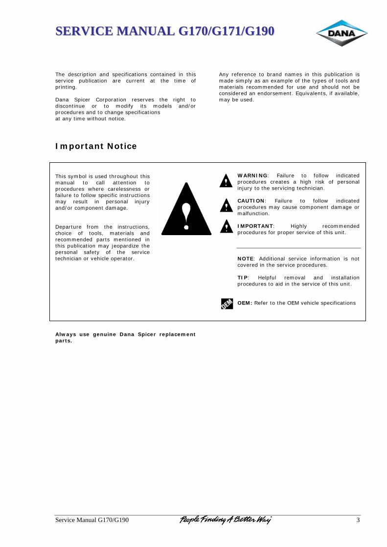
SSEERRVVIICCEE MMAANNUUAALL GG117700//GG117711//GG119900
Service Manual G170/G190 3
The description and specifications contained in this service publication are current at the time of printing. Dana Spicer Corporation reserves the right to discontinue or to modify its models and/or procedures and to change specifications at any time without notice.
Important Notice This symbol is used throughout this manual to call attention to procedures where carelessness or failure to follow specific instructions may result in personal injury and/or component damage. Departure from the instructions, choice of tools, materials and recommended parts mentioned in this publication may jeopardize the personal safety of the service technician or vehicle operator. Always use genuine Dana Spicer replacement parts.
Any reference to brand names in this publication is made simply as an example of the types of tools and materials recommended for use and should not be considered an endorsement. Equivalents, if available, may be used.
WARNING: Failure to follow indicated procedures creates a high risk of personal injury to the servicing technician. CAUTION: Failure to follow indicated procedures may cause component damage or malfunction. IMPORTANT: Highly recommended procedures for proper service of this unit. NOTE: Additional service information is not covered in the service procedures. TIP: Helpful removal and installation procedures to aid in the service of this unit. OEM: Refer to the OEM vehicle specifications
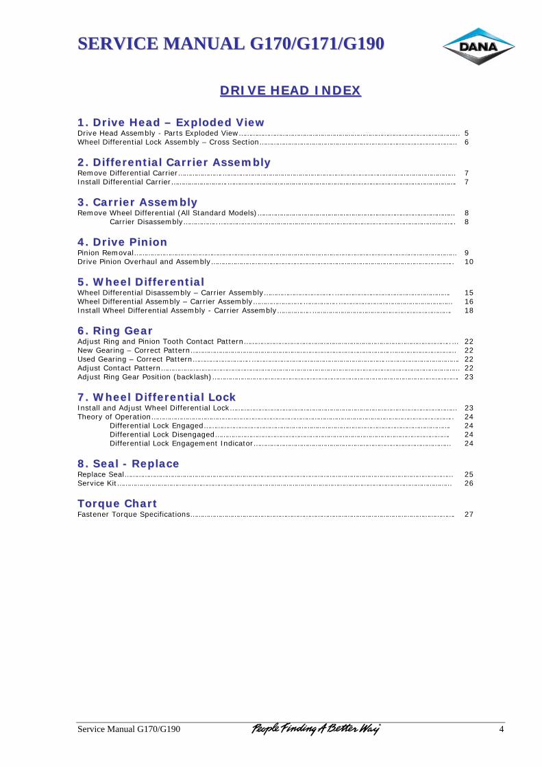
SSEERRVVIICCEE MMAANNUUAALL GG117700//GG117711//GG119900
Service Manual G170/G190 4
DDRRIIVVEE HHEEAADD IINNDDEEXX
11.. DDrriivvee HHeeaadd –– EExxppllooddeedd VViieeww Drive Head Assembly - Parts Exploded View………………………………………………………………………………………………… 5 Wheel Differential Lock Assembly – Cross Section……………………………………………………………………………………… 6
22.. DDiiffffeerreennttiiaall CCaarrrriieerr AAsssseemmbbllyy Remove Differential Carrier………………….……………………………………………………………………………………………………… 7 Install Differential Carrier……………………….……………………………………………………………………………………………………. 7
33.. CCaarrrriieerr AAsssseemmbbllyy Remove Wheel Differential (All Standard Models)……………………………………………………………………………………… 8
Carrier Disassembly……………..……………………………………………………………………………………………………….. 8
44.. DDrriivvee PPiinniioonn Pinion Removal……………………………………………………………………………………………………………………………………………… 9 Drive Pinion Overhaul and Assembly………………………………………………………………………………………………………….. 10
55.. WWhheeeell DDiiffffeerreennttiiaall Wheel Differential Disassembly – Carrier Assembly……………………………..…………………………………………………. 15 Wheel Differential Assembly – Carrier Assembly…………………….……………..………………………………………………… 16 Install Wheel Differential Assembly - Carrier Assembly……………..……………………………………………………………. 18
66.. RRiinngg GGeeaarr Adjust Ring and Pinion Tooth Contact Pattern…………………………………………………………………………………………..… 22 New Gearing – Correct Pattern……………………………………………………………………………………….…………………………… 22 Used Gearing – Correct Pattern………………………..………………………………………………………….………………………………. 22 Adjust Contact Pattern…………………………………………………………………………………………………………………………………… 22 Adjust Ring Gear Position (backlash)……………………………………………………………………………………………………………. 23
77.. WWhheeeell DDiiffffeerreennttiiaall LLoocckk Install and Adjust Wheel Differential Lock…………………………………………………………………………………………………… 23 Theory of Operation…………………………………………………………………………………………………………………………………….. 24
Differential Lock Engaged……………………………………………………………………………………………………………. 24 Differential Lock Disengaged………………………………………………………………………………………………………. 24 Differential Lock Engagement Indicator……………………………………………………………………………………… 24
88.. SSeeaall -- RReeppllaaccee Replace Seal………………………………………………………………………………………………………………………………………………… 25 Service Kit…………………………………………………………………………………………………………………………………………………… 26
TToorrqquuee CChhaarrtt Fastener Torque Specifications……………………………………………………………………………………………………………………. 27
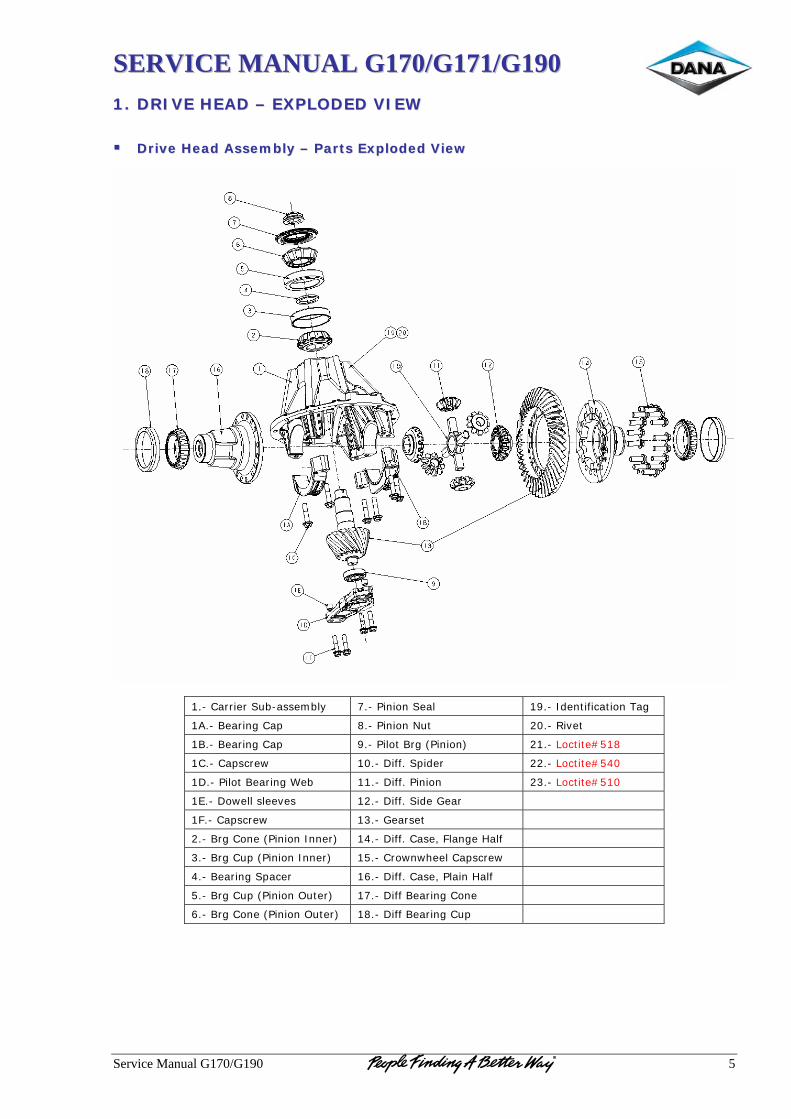
SSEERRVVIICCEE MMAANNUUAALL GG117700//GG117711//GG119900
Service Manual G170/G190 5
11.. DDRRIIVVEE HHEEAADD –– EEXXPPLLOODDEEDD VVIIEEWW
DDrriivvee HHeeaadd AAsssseemmbbllyy –– PPaarrttss EExxppllooddeedd VViieeww
1.- Carrier Sub-assembly 7.- Pinion Seal 19.- Identification Tag
1A.- Bearing Cap 8.- Pinion Nut 20.- Rivet
1B.- Bearing Cap 9.- Pilot Brg (Pinion) 21.- Loctite#518
1C.- Capscrew 10.- Diff. Spider 22.- Loctite#540
1D.- Pilot Bearing Web 11.- Diff. Pinion 23.- Loctite#510
1E.- Dowell sleeves 12.- Diff. Side Gear
1F.- Capscrew 13.- Gearset
2.- Brg Cone (Pinion Inner) 14.- Diff. Case, Flange Half
3.- Brg Cup (Pinion Inner) 15.- Crownwheel Capscrew
4.- Bearing Spacer 16.- Diff. Case, Plain Half
5.- Brg Cup (Pinion Outer) 17.- Diff Bearing Cone
6.- Brg Cone (Pinion Outer) 18.- Diff Bearing Cup
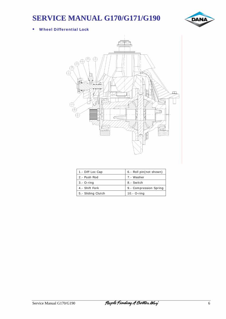
SSEERRVVIICCEE MMAANNUUAALL GG117700//GG117711//GG119900
Service Manual G170/G190 6
WWhheeeell DDiiffffeerreennttiiaall LLoocckk
1.- Diff Loc Cap 6.- Roll pin(not shown)
2.- Push Rod 7.- Washer
3.- O-ring 8.- Switch
4.- Shift Fork 9.- Compression Spring
5.- Sliding Clutch 10.- O-ring

SSEERRVVIICCEE MMAANNUUAALL GG117700//GG117711//GG119900
Service Manual G170/G190 7
22.. DDIIFFFFEERREENNTTIIAALL CCAARRRRIIEERR
AASSSSEEMMBBLLYY
RReemmoovvee DDiiffffeerreennttiiaall CCaarrrriieerr Standard Differentials 1. Block the vehicle 2. Drain axle lubricant. 3. Disconnect driveline. 4. Disconnect lead wires to the selector switch
and air line at shift cylinder. 5. Remove axle shaft. WARNING: Do not lie under carrier after fasteners are removed. Use transmission jack to support differential carrier assembly prior to loosening fasteners. 6. To remove axle shaft, remove axle stud nuts.
(If used, remove lock washers and taper dowels.)
7. Remove axle shafts. NOTE: All models in this publication use axle shafts with unequal lengths. Axle shafts may also be location specific with various wheelequipment. Do not misplace axle shafts from their intended location. Identify left and right shafts for reference during reassembly. TIP: If necessary, loosen dowels by holding a brass drift in the center of the shaft head and striking drift with a sharp blow with a hammer. CAUTION: Do not strike the shaft head with a steel hammer. Do not use chisels or wedges to loosen shaft or dowels. 8. Remove carrier capscrews, nuts, and lock
washers. 9. Remove differential carrier assembly.
IInnssttaallll DDiiffffeerreennttiiaall CCaarrrriieerr IMPORTANT: Before installing carrier assembly, inspect and thoroughly clean interior of axle housing using an appropiated solvent and clean rag. 1. Use silicone rubber gasket compound or
Loctite#518 on axle housing mating surface as shown in the illustration. Gasket compound will set in 20 minutes. Install carrier before compound sets or reapply.
TIP: To assist in installing complete differential carrier use two pieces of threaded rod (M16 X 1.5) threaded into carrier capscrew holes. Rod should be approximately 6" long. Use these to pilot the carrier into the housing. NOTE: Fasteners using self-locking thread “patches” may be reused if not damaged, but should be secured by a few drops of Loctite#518 on threaded surface of differential carrier. Reused fasteners should be wiped clean of excess oil, but do not require special cleaning. 2. Install carrier to housing, lock washers,
capscrews and nuts. Torque to proper specification. (see torque chart).
3. Install axle shafts and axle stud nuts. (If
used, also install lock washers and tapered dowels.)
4. Add axle lubricant. Fill to bottom of filler
hole. 5. Connect driveline, making sure all yokes are
in phase. Lubricate u-joints. NOTE: When axle has been disassembled or housing, gears, axle shafts or wheel equipment replaced, check axle assembly for proper differential action before operating vehicle. Wheels must rotate freely and independently.
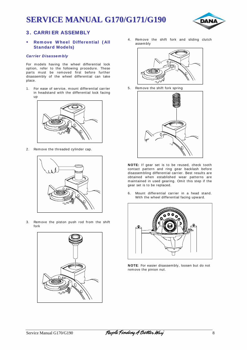
SSEERRVVIICCEE MMAANNUUAALL GG117700//GG117711//GG119900
Service Manual G170/G190 8
33.. CCAARRRRIIEERR AASSSSEEMMBBLLYY
RReemmoovvee WWhheeeell DDiiffffeerreennttiiaall ((AAllll SSttaannddaarrdd MMooddeellss))
CCaarrrriieerr DDiissaasssseemmbbllyy For models having the wheel differential lock option, refer to the following procedure. These parts must be removed first before further disassembly of the wheel differential can take place. 1. For ease of service, mount differential carrier
in headstand with the differential lock facing up
2. Remove the threaded cylinder cap. 3. Remove the piston push rod from the shift
fork
4. Remove the shift fork and sliding clutch
assembly 5. Remove the shift fork spring NOTE: If gear set is to be reused, check tooth contact pattern and ring gear backlash before disassembling differential carrier. Best results are obtained when established wear patterns are maintained in used gearing. Omit this step if the gear set is to be replaced. 6. Mount differential carrier in a head stand.
With the wheel differential facing upward.
NOTE: For easier disassembly, loosen but do not remove the pinion nut.
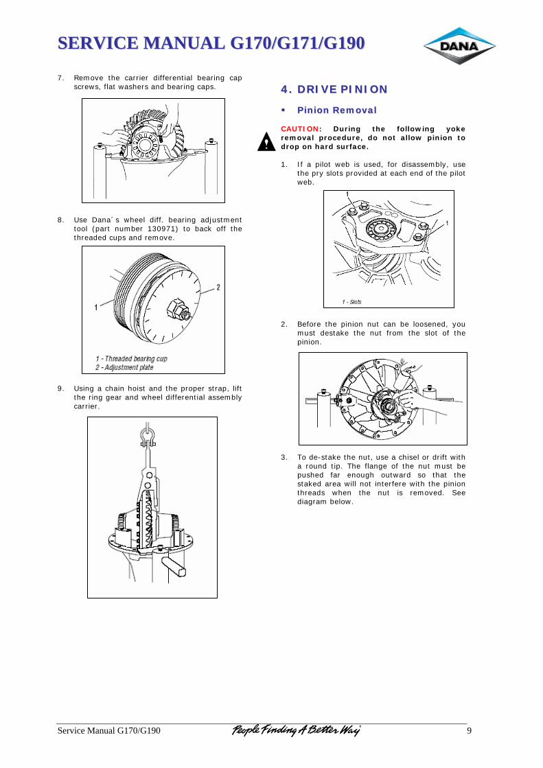
SSEERRVVIICCEE MMAANNUUAALL GG117700//GG117711//GG119900
Service Manual G170/G190 9
7. Remove the carrier differential bearing cap
screws, flat washers and bearing caps. 8. Use Dana´s wheel diff. bearing adjustment
tool (part number 130971) to back off the threaded cups and remove.
9. Using a chain hoist and the proper strap, lift
the ring gear and wheel differential assembly carrier.
44.. DDRRIIVVEE PPIINNIIOONN
PPiinniioonn RReemmoovvaall CAUTION: During the following yoke removal procedure, do not allow pinion to drop on hard surface. 1. If a pilot web is used, for disassembly, use
the pry slots provided at each end of the pilot web.
2. Before the pinion nut can be loosened, you
must destake the nut from the slot of the pinion.
3. To de-stake the nut, use a chisel or drift with
a round tip. The flange of the nut must be pushed far enough outward so that the staked area will not interfere with the pinion threads when the nut is removed. See diagram below.
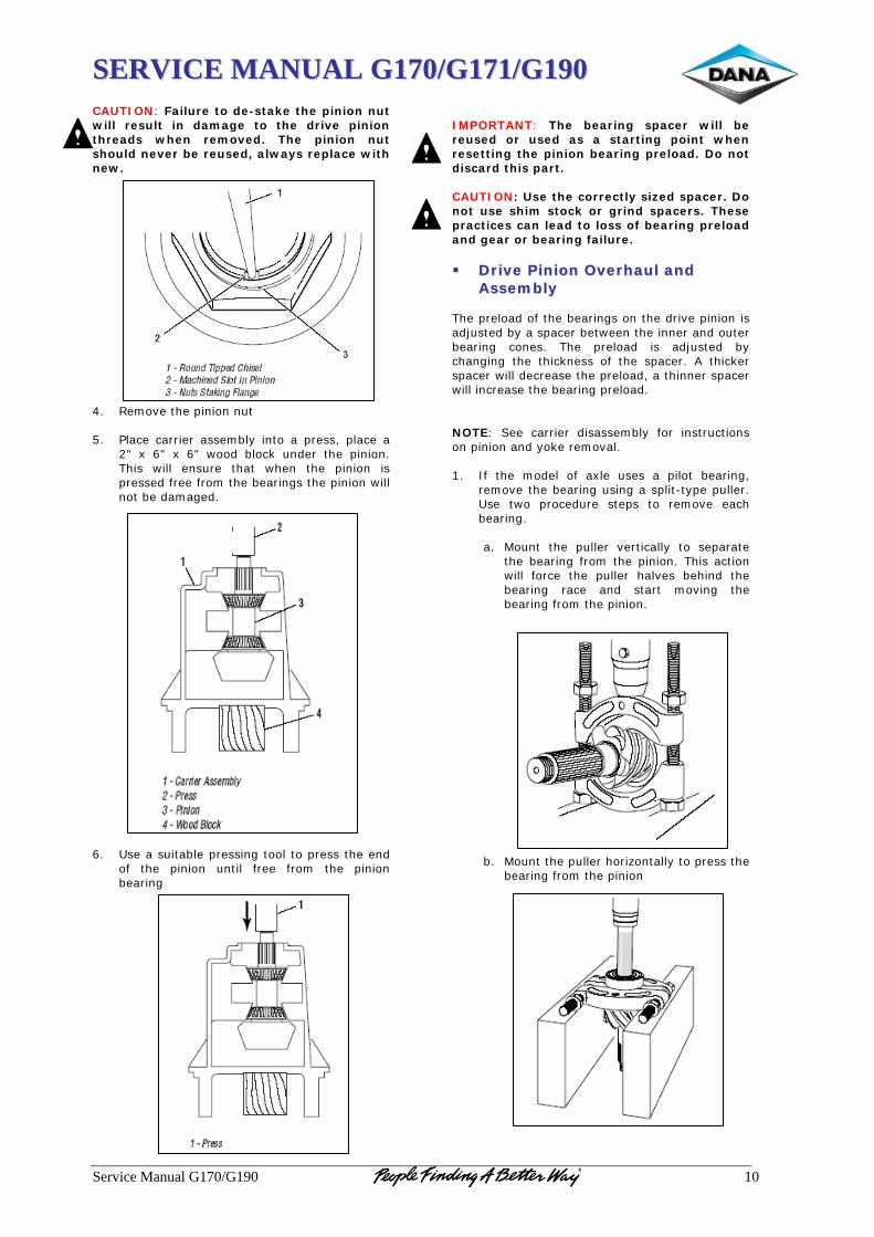
SSEERRVVIICCEE MMAANNUUAALL GG117700//GG117711//GG119900
Service Manual G170/G190 10
CAUTION: Failure to de-stake the pinion nut will result in damage to the drive pinion threads when removed. The pinion nut should never be reused, always replace with new. 4. Remove the pinion nut 5. Place carrier assembly into a press, place a
2" x 6" x 6" wood block under the pinion. This will ensure that when the pinion is pressed free from the bearings the pinion will not be damaged.
6. Use a suitable pressing tool to press the end
of the pinion until free from the pinion bearing
IMPORTANT: The bearing spacer will be reused or used as a starting point when resetting the pinion bearing preload. Do not discard this part. CAUTION: Use the correctly sized spacer. Do not use shim stock or grind spacers. These practices can lead to loss of bearing preload and gear or bearing failure.
DDrriivvee PPiinniioonn OOvveerrhhaauull aanndd AAsssseemmbbllyy
The preload of the bearings on the drive pinion is adjusted by a spacer between the inner and outer bearing cones. The preload is adjusted by changing the thickness of the spacer. A thicker spacer will decrease the preload, a thinner spacer will increase the bearing preload. NOTE: See carrier disassembly for instructions on pinion and yoke removal. 1. If the model of axle uses a pilot bearing,
remove the bearing using a split-type puller. Use two procedure steps to remove each bearing.
a. Mount the puller vertically to separate
the bearing from the pinion. This action will force the puller halves behind the bearing race and start moving the bearing from the pinion.
b. Mount the puller horizontally to press the bearing from the pinion
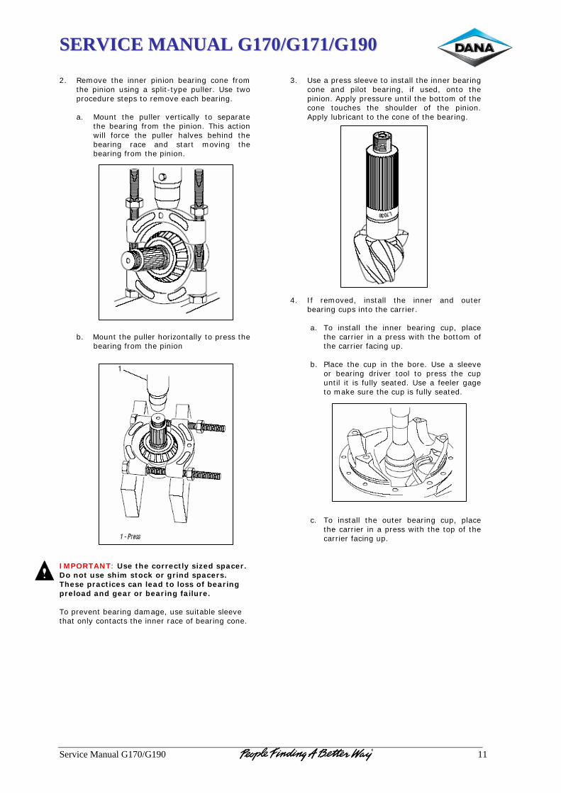
SSEERRVVIICCEE MMAANNUUAALL GG117700//GG117711//GG119900
Service Manual G170/G190 11
2. Remove the inner pinion bearing cone from
the pinion using a split-type puller. Use two procedure steps to remove each bearing.
a. Mount the puller vertically to separate
the bearing from the pinion. This action will force the puller halves behind the bearing race and start moving the bearing from the pinion.
b. Mount the puller horizontally to press the bearing from the pinion
IMPORTANT: Use the correctly sized spacer. Do not use shim stock or grind spacers. These practices can lead to loss of bearing preload and gear or bearing failure. To prevent bearing damage, use suitable sleeve that only contacts the inner race of bearing cone.
3. Use a press sleeve to install the inner bearing
cone and pilot bearing, if used, onto the pinion. Apply pressure until the bottom of the cone touches the shoulder of the pinion. Apply lubricant to the cone of the bearing.
4. If removed, install the inner and outer
bearing cups into the carrier.
a. To install the inner bearing cup, place the carrier in a press with the bottom of the carrier facing up.
b. Place the cup in the bore. Use a sleeve
or bearing driver tool to press the cup until it is fully seated. Use a feeler gage to make sure the cup is fully seated.
c. To install the outer bearing cup, place
the carrier in a press with the top of the carrier facing up.
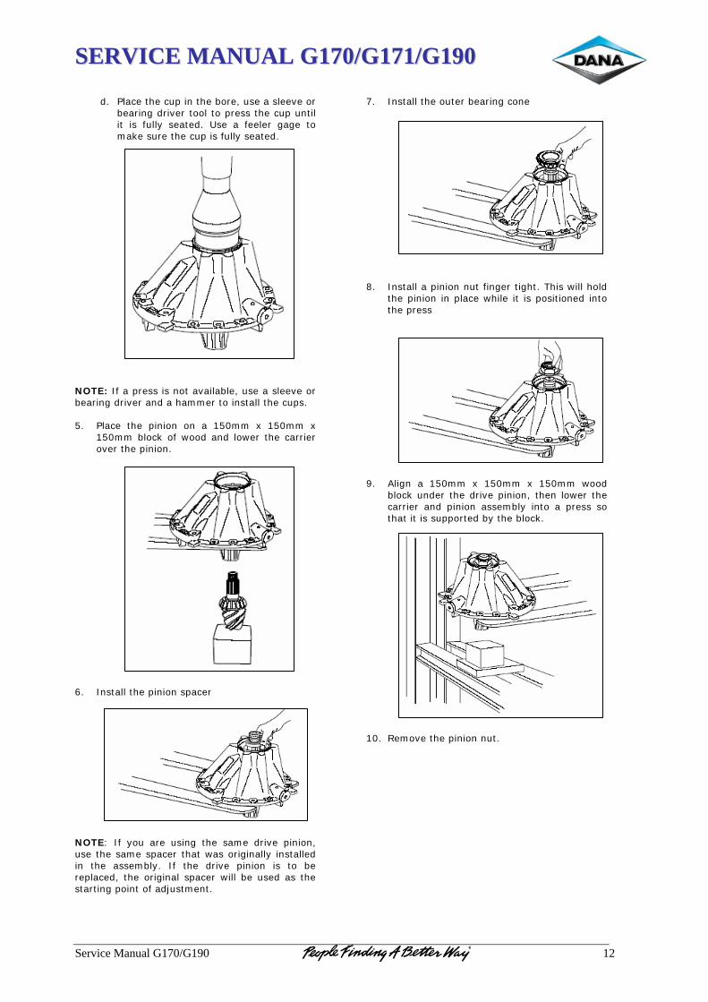
SSEERRVVIICCEE MMAANNUUAALL GG117700//GG117711//GG119900
Service Manual G170/G190 12
d. Place the cup in the bore, use a sleeve or
bearing driver tool to press the cup until it is fully seated. Use a feeler gage to make sure the cup is fully seated.
NOTE: If a press is not available, use a sleeve or bearing driver and a hammer to install the cups. 5. Place the pinion on a 150mm x 150mm x
150mm block of wood and lower the carrier over the pinion.
6. Install the pinion spacer NOTE: If you are using the same drive pinion, use the same spacer that was originally installed in the assembly. If the drive pinion is to be replaced, the original spacer will be used as the starting point of adjustment.
7. Install the outer bearing cone 8. Install a pinion nut finger tight. This will hold
the pinion in place while it is positioned into the press
9. Align a 150mm x 150mm x 150mm wood
block under the drive pinion, then lower the carrier and pinion assembly into a press so that it is supported by the block.
10. Remove the pinion nut.
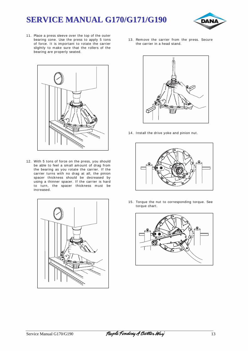
SSEERRVVIICCEE MMAANNUUAALL GG117700//GG117711//GG119900
Service Manual G170/G190 13
11. Place a press sleeve over the top of the outer
bearing cone. Use the press to apply 5 tons of force. It is important to rotate the carrier slightly to make sure that the rollers of the bearing are properly seated.
12. With 5 tons of force on the press, you should
be able to feel a small amount of drag from the bearing as you rotate the carrier. If the carrier turns with no drag at all, the pinion spacer thickness should be decreased by using a thinner spacer. If the carrier is hard to turn, the spacer thickness must be increased.
13. Remove the carrier from the press. Secure
the carrier in a head stand. 14. Install the drive yoke and pinion nut. 15. Torque the nut to corresponding torque. See
torque chart.
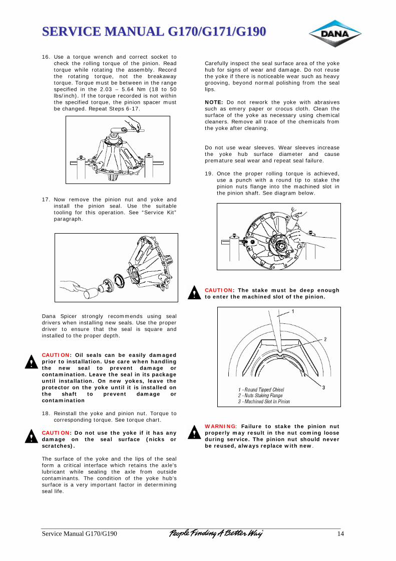
SSEERRVVIICCEE MMAANNUUAALL GG117700//GG117711//GG119900
Service Manual G170/G190 14
16. Use a torque wrench and correct socket to
check the rolling torque of the pinion. Read torque while rotating the assembly. Record the rotating torque, not the breakaway torque. Torque must be between in the range specified in the 2.03 – 5.64 Nm (18 to 50 lbs/inch). If the torque recorded is not within the specified torque, the pinion spacer must be changed. Repeat Steps 6-17.
17. Now remove the pinion nut and yoke and
install the pinion seal. Use the suitable tooling for this operation. See “Service Kit” paragraph.
Dana Spicer strongly recommends using seal drivers when installing new seals. Use the proper driver to ensure that the seal is square and installed to the proper depth. CAUTION: Oil seals can be easily damaged prior to installation. Use care when handling the new seal to prevent damage or contamination. Leave the seal in its package until installation. On new yokes, leave the protector on the yoke until it is installed on the shaft to prevent damage or contamination 18. Reinstall the yoke and pinion nut. Torque to
corresponding torque. See torque chart. CAUTION: Do not use the yoke if it has any damage on the seal surface (nicks or scratches). The surface of the yoke and the lips of the seal form a critical interface which retains the axle’s lubricant while sealing the axle from outside contaminants. The condition of the yoke hub’s surface is a very important factor in determining seal life.
Carefully inspect the seal surface area of the yoke hub for signs of wear and damage. Do not reuse the yoke if there is noticeable wear such as heavy grooving, beyond normal polishing from the seal lips. NOTE: Do not rework the yoke with abrasives such as emery paper or crocus cloth. Clean the surface of the yoke as necessary using chemical cleaners. Remove all trace of the chemicals from the yoke after cleaning. Do not use wear sleeves. Wear sleeves increase the yoke hub surface diameter and cause premature seal wear and repeat seal failure. 19. Once the proper rolling torque is achieved,
use a punch with a round tip to stake the pinion nuts flange into the machined slot in the pinion shaft. See diagram below.
CAUTION: The stake must be deep enough to enter the machined slot of the pinion. WARNING: Failure to stake the pinion nut properly may result in the nut coming loose during service. The pinion nut should never be reused, always replace with new.

SSEERRVVIICCEE MMAANNUUAALL GG117700//GG117711//GG119900
Service Manual G170/G190 15
20. If a pilot bearing web is used, line up the
web to the dowell sleeves and tap in place with a rubber mallet.
21. Install capscrews and torque to the proper
specifications. See the torque chart
55.. WWHHEEEELL DDIIFFFFEERREENNTTIIAALL
WWhheeeell DDiiffffeerreennttiiaall DDiissaasssseemmbbllyy ––CCaarrrriieerr AAsssseemmbbllyy
IMPORTANT: During following procedure, place differential assembly on malleable surface to prevent damage when removing components. 1. Remove cap screws fastening ring gear to
differential case.
2. Remove the flange half differential case and
bearing assembly. Use a screwdriver at the spider arm machined slots of the case to loosen the flange from the ring gear.
3. Remove the side gears, pinion gears and
differential spider from the plain half case.
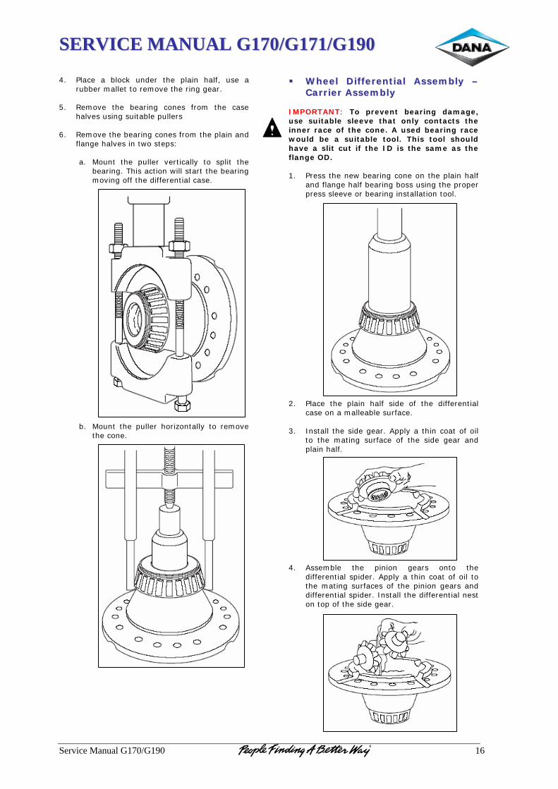
SSEERRVVIICCEE MMAANNUUAALL GG117700//GG117711//GG119900
Service Manual G170/G190 16
4. Place a block under the plain half, use a
rubber mallet to remove the ring gear. 5. Remove the bearing cones from the case
halves using suitable pullers 6. Remove the bearing cones from the plain and
flange halves in two steps:
a. Mount the puller vertically to split the bearing. This action will start the bearing moving off the differential case.
b. Mount the puller horizontally to remove the cone.
WWhheeeell DDiiffffeerreennttiiaall AAsssseemmbbllyy ––CCaarrrriieerr AAsssseemmbbllyy
IMPORTANT: To prevent bearing damage, use suitable sleeve that only contacts the inner race of the cone. A used bearing race would be a suitable tool. This tool should have a slit cut if the ID is the same as the flange OD. 1. Press the new bearing cone on the plain half
and flange half bearing boss using the proper press sleeve or bearing installation tool.
2. Place the plain half side of the differential
case on a malleable surface. 3. Install the side gear. Apply a thin coat of oil
to the mating surface of the side gear and plain half.
4. Assemble the pinion gears onto the
differential spider. Apply a thin coat of oil to the mating surfaces of the pinion gears and differential spider. Install the differential nest on top of the side gear.
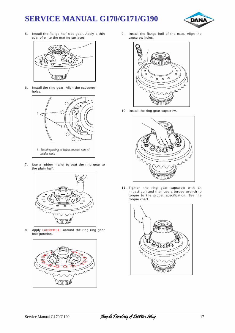
SSEERRVVIICCEE MMAANNUUAALL GG117700//GG117711//GG119900
Service Manual G170/G190 17
5. Install the flange half side gear. Apply a thin
coat of oil to the mating surfaces
6. Install the ring gear. Align the capscrew
holes.
7. Use a rubber mallet to seat the ring gear to
the plain half. 8. Apply Loctite#510 around the ring ring gear
bolt junction.
9. Install the flange half of the case. Align the
capscrew holes. 10. Install the ring gear capscrew.
11. Tighten the ring gear capscrew with an
impact gun and then use a torque wrench to torque to the proper specification. See the torque chart.
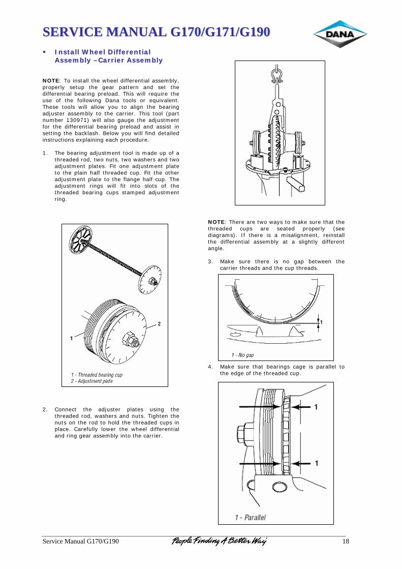
SSEERRVVIICCEE MMAANNUUAALL GG117700//GG117711//GG119900
Service Manual G170/G190 18
IInnssttaallll WWhheeeell DDiiffffeerreennttiiaall AAsssseemmbbllyy ––CCaarrrriieerr AAsssseemmbbllyy
NOTE: To install the wheel differential assembly, properly setup the gear pattern and set the differential bearing preload. This will require the use of the following Dana tools or equivalent. These tools will allow you to align the bearing adjuster assembly to the carrier. This tool (part number 130971) will also gauge the adjustment for the differential bearing preload and assist in setting the backlash. Below you will find detailed instructions explaining each procedure. 1. The bearing adjustment tool is made up of a
threaded rod, two nuts, two washers and two adjustment plates. Fit one adjustment plate to the plain half threaded cup. Fit the other adjustment plate to the flange half cup. The adjustment rings will fit into slots of the threaded bearing cups stamped adjustment ring.
2. Connect the adjuster plates using the
threaded rod, washers and nuts. Tighten the nuts on the rod to hold the threaded cups in place. Carefully lower the wheel differential and ring gear assembly into the carrier.
NOTE: There are two ways to make sure that the threaded cups are seated properly (see diagrams). If there is a misalignment, reinstall the differential assembly at a slightly different angle. 3. Make sure there is no gap between the
carrier threads and the cup threads.
4. Make sure that bearings cage is parallel to
the edge of the threaded cup.
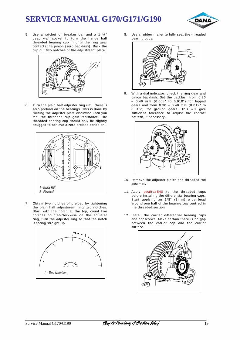
SSEERRVVIICCEE MMAANNUUAALL GG117700//GG117711//GG119900
Service Manual G170/G190 19
5. Use a ratchet or breaker bar and a 1 ¼"
deep wall socket to turn the flange half threaded bearing cup in until the ring gear contacts the pinion (zero backlash). Back the cup out two notches of the adjustment plate.
6. Turn the plain half adjuster ring until there is
zero preload on the bearings. This is done by turning the adjuster plate clockwise until you feel the threaded cup gain resistance. The threaded bearing cup should only be slightly snugged to achieve a zero preload condition.
7. Obtain two notches of preload by tightening
the plain half adjustment ring two notches. Start with the notch at the top, count two notches counter-clockwise on the adjuster ring, turn the adjuster ring so that the notch is facing straight up.
8. Use a rubber mallet to fully seat the threaded
bearing cups.
9. With a dial indicator, check the ring gear and
pinion backlash. Set the backlash from 0.20 – 0.46 mm (0.008" to 0.018") for lapped gears and from 0.30 – 0.40 mm (0.012" to 0.016") for ground gears. This will give sufficient tolerance to adjust the contact pattern, if necessary.
10. Remove the adjuster plates and threaded rod
assembly. 11. Apply Loctite#540 to the threaded cups
before installing the differential bearing caps. Start applying an 1/8" (3mm) wide bead around one half of the bearing cup centred in the threaded section
12. Install the carrier differential bearing caps
and capscrews. Make certain there is no gap between the carrier cap and the carrier surface.

SSEERRVVIICCEE MMAANNUUAALL GG117700//GG117711//GG119900
Service Manual G170/G190 20
13. Use an impact gun to snug all carrier
differential bearing cap fasteners.
14. Recheck the backlash. For new gearing, the
backlash should be between 0.20 and 0.46 mm (0.008" - 0.018").
NOTE: For used gearing, the backlash should be reset to what it was at the time of disassembly. NOTE: If you have too much backlash, move the ring gear closer to the pinion. Count the number of notches you back off the plain half threaded cup. Each notch equals about 0.003" (0.08 mm) of backlash. IMPORTANT: In order to maintain the differential bearing preload, you will need to turn the flange half threaded cup the same amount in the same direction. If you need more backlash, reverse the procedure. 15. Measure the ring gear total radial runout.
Indicator reading should not exceed 0.010" (0.25 mm).
16. Measure the ring gear total backface runout.
Indicator reading should not exceed 0.006" (0.15 mm).
17. Check the ring gear tooth pattern. Paint 5 or
6 ring gear teeth 180 degrees apart on the ring gear.
18. With the carrier mounted in a head stand,
roll the carrier in its side. 19. Make a sling out of a strap and position
around the plain half of the wheel differential.

SSEERRVVIICCEE MMAANNUUAALL GG117700//GG117711//GG119900
Service Manual G170/G190 21
20. Connect the end of the strap to a hoist and
apply pressure to the sling 21. Use the correct socket and a breaker bar to
rotate the differential. The differential should be hard to turn. Rotate the pinion until the ring gear rotates 3 or 4 times in both directions. See next pages for descriptions of correct pattern position for new and used gearing.
22. When contact pattern and backlash are
correct. Using a torque wrench tighten both carrier differential bearing caps to the specified torque. See the torque chart. Recheck backlash and contact pattern.
23. Use a punch with a round head to stake the
threaded bearing cups in place. Stake the outer edge of the bearing adjustment ring into the machined slots in the carrier bearing bore on both sides. Must be staked at two locations. Rotate cup if necessary to provide surfaces for staking.

SSEERRVVIICCEE MMAANNUUAALL GG117700//GG117711//GG119900
Service Manual G170/G190 22
66.. RRIINNGG GGEEAARR
AAddjjuusstt RRiinngg AAnndd PPiinniioonn TTooootthh CCoonnttaacctt PPaatttteerrnn
NOTE: Rear axle gearing is shown in the following instructions.
1.- Identify if new or used gearings 2.- Check tooth contact pattern (new or used gearings)
NNeeww GGeeaarriinngg -- CCoorrrreecctt PPaatttteerrnn Paint six ring gear teeth 180° apart with marking compound and roll the gear to obtain a contact pattern. The correct pattern is slightly below center on the ring gear tooth with lengthwise contact up off the toe. The length of the pattern in an unloaded condition is approximately one-half to two-thirds of the ring gear tooth in most models and ratios. The pattern could vary in length and should cover 1/2 tooth or more (face width). The pattern should be evenly centered between tooth top land and root and should be up off the tooth toe.
UUsseedd GGeeaarriinngg -- CCoorrrreecctt PPaatttteerrnn Used gearing will not usually display the square, even contact pattern found in new gear sets. The gear will normally have a "pocket" at the heal end of the gear tooth. The more use a gear has had, the more the line becomes the dominant characteristic of the pattern. Adjust used gear sets to display the same contact pattern observed before disassembly. A correct pattern is up off the toe and centers evenly along the face width between the top land and root. Otherwise, the length and shape of the pattern are highly variable and is considered acceptable as long as it does not run off the tooth at any point.
1. Pattern along the face width could be longer.
AAddjjuusstt CCoonnttaacctt PPaatttteerrnn If necessary, adjust the contact pattern by moving the ring gear.
• Ring gear position controls the backlash. This adjustment also moves the contact pattern along the face width of the gear tooth.

SSEERRVVIICCEE MMAANNUUAALL GG117700//GG117711//GG119900
Service Manual G170/G190 23
AAddjjuusstt RRiinngg GGeeaarr PPoossiittiioonn ((BBaacckkllaasshh))
If the gear pattern shows incorrect face width contact, change backlash by adjusting the ring gear. If the pattern is too close to the edge of the tooth toe, move the ring gear away from the pinion to increase backlash. 1. Loosen the bearing adjuster on the flange
side of the ring gear several notches. 2. Tighten the opposite adjuster one notch 3. Return to adjuster on flange side of ring gear
and tighten adjuster until it contacts the bearing cup.
4. Continue tightening the same adjuster two or
three notches and recheck backlash. If the pattern is concentrated at the heel (too far up the tooth), move the ring gear toward the pinion to decrease backlash. 1. Loosen the bearing adjuster on the teeth side
of the ring gear several notches. 2. Tighten the opposite adjuster one notch 3. Return to adjuster on teeth side of ring gear
and tighten adjuster until it contacts the bearing cup.
4. Continue tightening the same adjuster two or
three notches and recheck backlash.
77.. WWHHEEEELL DDIIFFFFEERREENNTTIIAALL LLOOCCKK
IInnssttaallll aanndd AAddjjuusstt WWhheeeell DDiiffffeerreennttiiaall LLoocckk
NOTE: With differential carrier completely assembled and adjusted, install differential lock as follows: 1. If shift fork and sliding clutch are
disassembled, engage fork with the clutch hub and install roll pin in the fork leg. See illustration below for fork mounting position on clutch.
2. Position compression spring, shift fork and
clutch in shift opening of the carrier. Align pilot hole of shift fork with the pilot hole of carrier
3. Install pushrod through shift fork,
compression spring and carrier pilot hole 4. Lubricate piston and o-ring with Lubriplate
No. 110. Install shift piston assembly into cylinder. Position piston with small diameter hub toward closed end of cylinder.
5. Install piston cover o-ring. 6. Install piston cover and tighten according
with torque chart 7. Install selector switch and and tighten
according with torque chart 8. Check selector switch operation. Check
switch electrically with an ohm meter. Switch should be closed when clutches are engaged and open when disengaged.
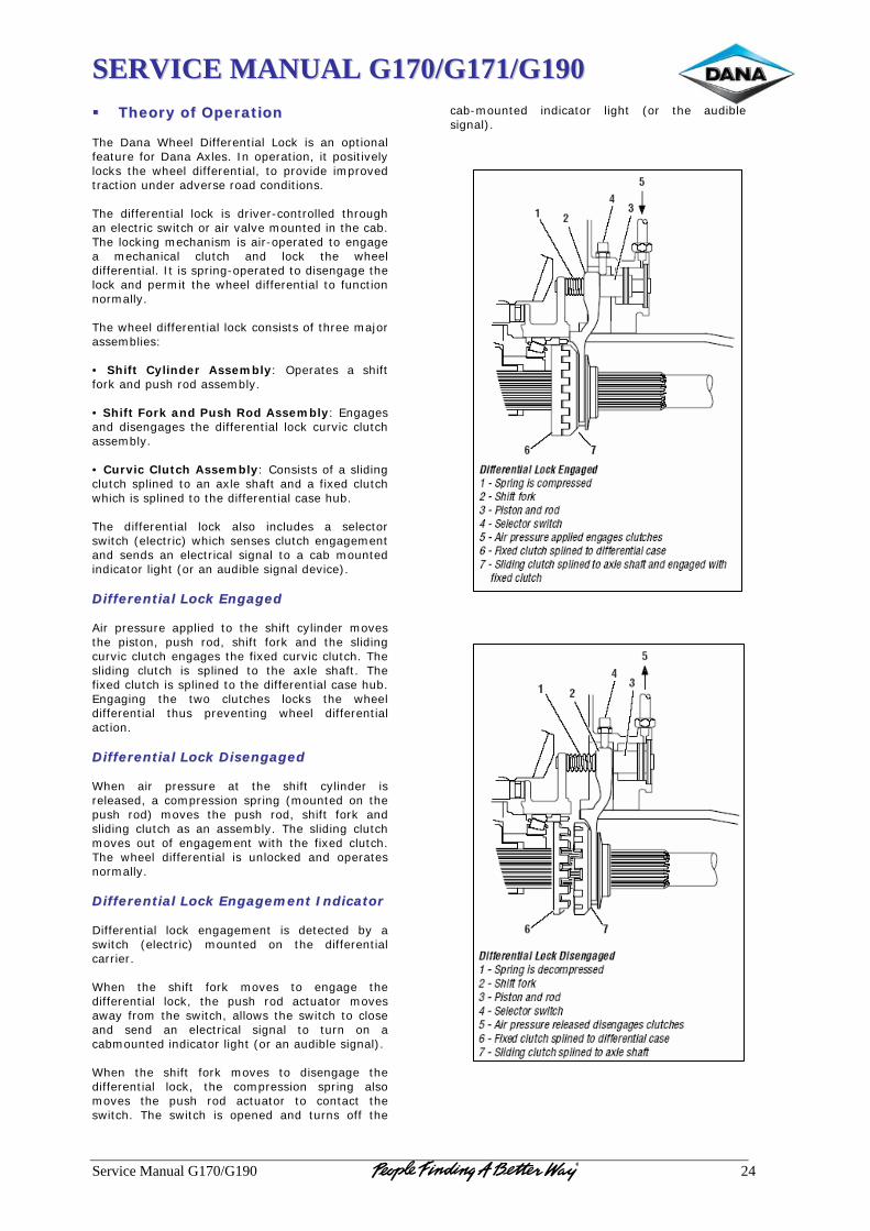
SSEERRVVIICCEE MMAANNUUAALL GG117700//GG117711//GG119900
Service Manual G170/G190 24
TThheeoorryy ooff OOppeerraattiioonn The Dana Wheel Differential Lock is an optional feature for Dana Axles. In operation, it positively locks the wheel differential, to provide improved traction under adverse road conditions. The differential lock is driver-controlled through an electric switch or air valve mounted in the cab. The locking mechanism is air-operated to engage a mechanical clutch and lock the wheel differential. It is spring-operated to disengage the lock and permit the wheel differential to function normally. The wheel differential lock consists of three major assemblies: • Shift Cylinder Assembly: Operates a shift fork and push rod assembly. • Shift Fork and Push Rod Assembly: Engages and disengages the differential lock curvic clutch assembly. • Curvic Clutch Assembly: Consists of a sliding clutch splined to an axle shaft and a fixed clutch which is splined to the differential case hub. The differential lock also includes a selector switch (electric) which senses clutch engagement and sends an electrical signal to a cab mounted indicator light (or an audible signal device). DDiiffffeerreennttiiaall LLoocckk EEnnggaaggeedd Air pressure applied to the shift cylinder moves the piston, push rod, shift fork and the sliding curvic clutch engages the fixed curvic clutch. The sliding clutch is splined to the axle shaft. The fixed clutch is splined to the differential case hub. Engaging the two clutches locks the wheel differential thus preventing wheel differential action. DDiiffffeerreennttiiaall LLoocckk DDiisseennggaaggeedd When air pressure at the shift cylinder is released, a compression spring (mounted on the push rod) moves the push rod, shift fork and sliding clutch as an assembly. The sliding clutch moves out of engagement with the fixed clutch. The wheel differential is unlocked and operates normally. DDiiffffeerreennttiiaall LLoocckk EEnnggaaggeemmeenntt IInnddiiccaattoorr Differential lock engagement is detected by a switch (electric) mounted on the differential carrier. When the shift fork moves to engage the differential lock, the push rod actuator moves away from the switch, allows the switch to close and send an electrical signal to turn on a cabmounted indicator light (or an audible signal). When the shift fork moves to disengage the differential lock, the compression spring also moves the push rod actuator to contact the switch. The switch is opened and turns off the
cab-mounted indicator light (or the audible signal).
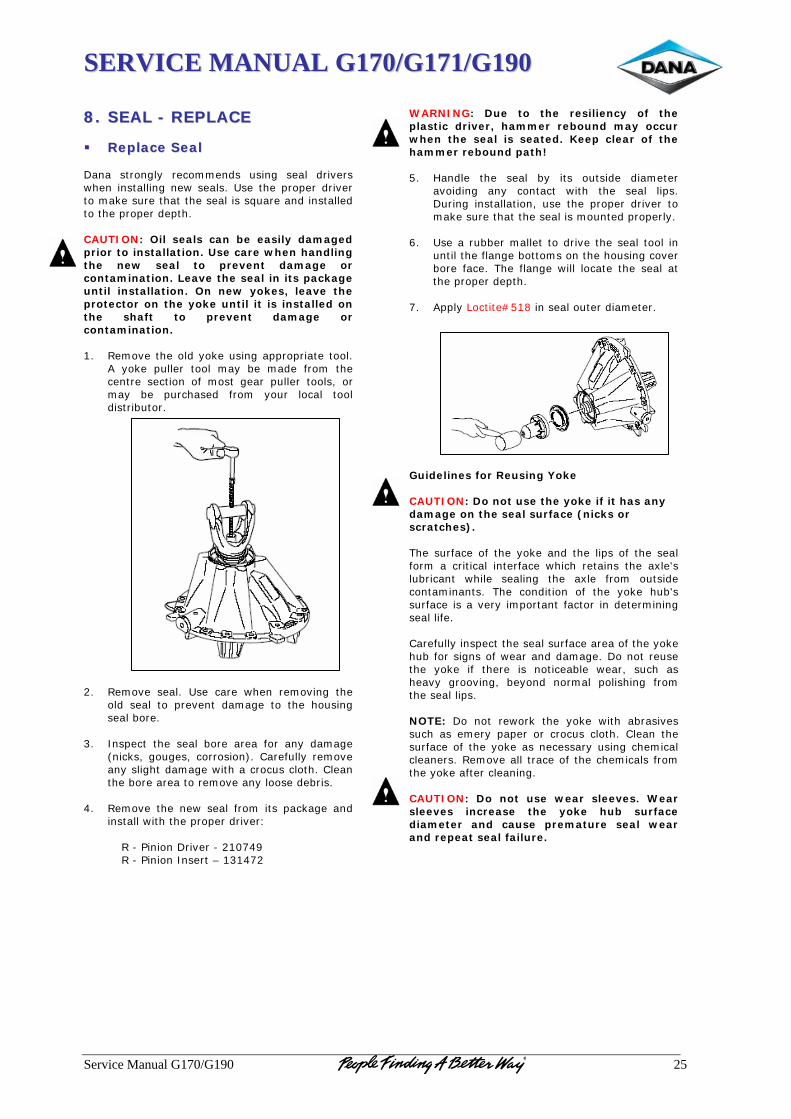
SSEERRVVIICCEE MMAANNUUAALL GG117700//GG117711//GG119900
Service Manual G170/G190 25
88.. SSEEAALL -- RREEPPLLAACCEE
RReeppllaaccee SSeeaall Dana strongly recommends using seal drivers when installing new seals. Use the proper driver to make sure that the seal is square and installed to the proper depth. CAUTION: Oil seals can be easily damaged prior to installation. Use care when handling the new seal to prevent damage or contamination. Leave the seal in its package until installation. On new yokes, leave the protector on the yoke until it is installed on the shaft to prevent damage or contamination. 1. Remove the old yoke using appropriate tool.
A yoke puller tool may be made from the centre section of most gear puller tools, or may be purchased from your local tool distributor.
2. Remove seal. Use care when removing the
old seal to prevent damage to the housing seal bore.
3. Inspect the seal bore area for any damage
(nicks, gouges, corrosion). Carefully remove any slight damage with a crocus cloth. Clean the bore area to remove any loose debris.
4. Remove the new seal from its package and
install with the proper driver:
R - Pinion Driver - 210749 R - Pinion Insert – 131472
WARNING: Due to the resiliency of the plastic driver, hammer rebound may occur when the seal is seated. Keep clear of the hammer rebound path! 5. Handle the seal by its outside diameter
avoiding any contact with the seal lips. During installation, use the proper driver to make sure that the seal is mounted properly.
6. Use a rubber mallet to drive the seal tool in
until the flange bottoms on the housing cover bore face. The flange will locate the seal at the proper depth.
7. Apply Loctite#518 in seal outer diameter. Guidelines for Reusing Yoke CAUTION: Do not use the yoke if it has any damage on the seal surface (nicks or scratches). The surface of the yoke and the lips of the seal form a critical interface which retains the axle's lubricant while sealing the axle from outside contaminants. The condition of the yoke hub's surface is a very important factor in determining seal life. Carefully inspect the seal surface area of the yoke hub for signs of wear and damage. Do not reuse the yoke if there is noticeable wear, such as heavy grooving, beyond normal polishing from the seal lips. NOTE: Do not rework the yoke with abrasives such as emery paper or crocus cloth. Clean the surface of the yoke as necessary using chemical cleaners. Remove all trace of the chemicals from the yoke after cleaning. CAUTION: Do not use wear sleeves. Wear sleeves increase the yoke hub surface diameter and cause premature seal wear and repeat seal failure.
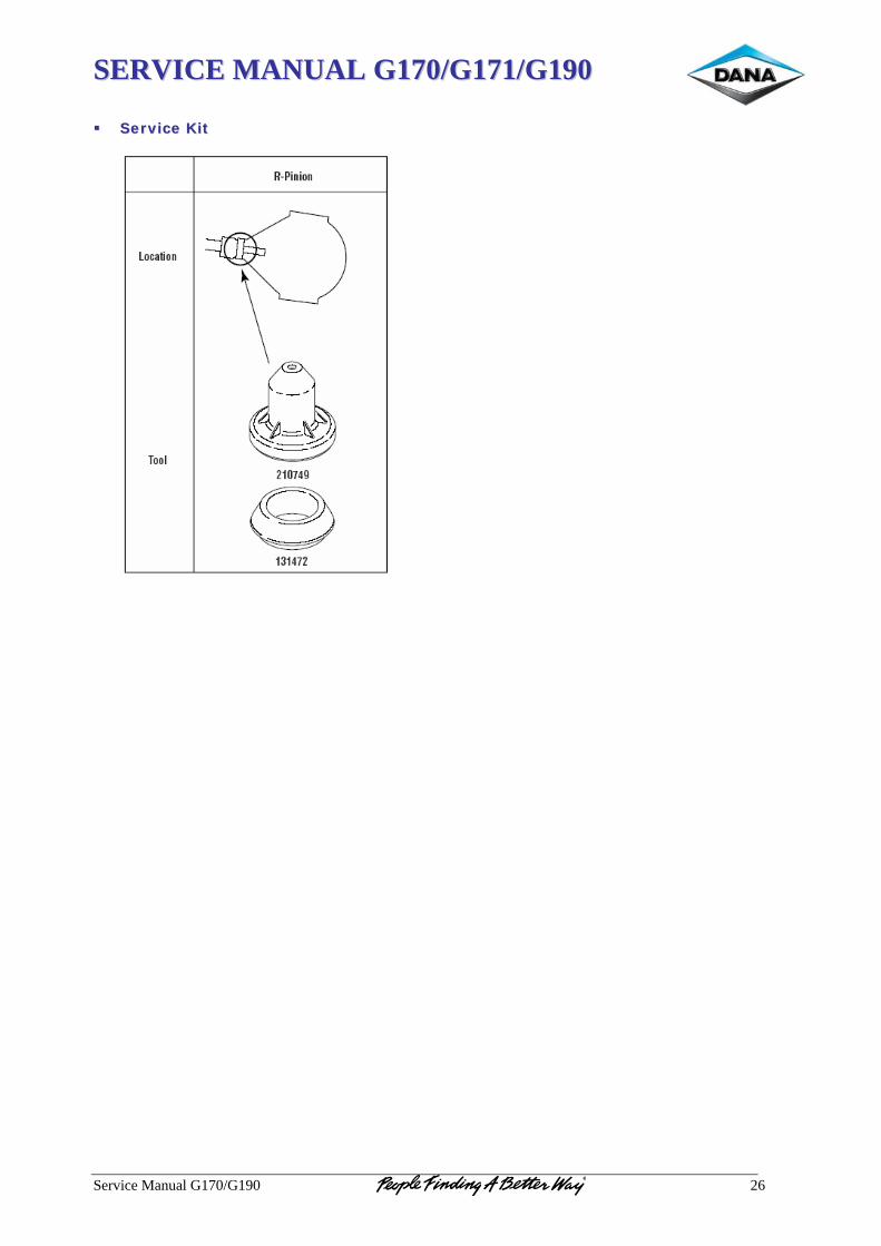
SSEERRVVIICCEE MMAANNUUAALL GG117700//GG117711//GG119900
Service Manual G170/G190 26
SSeerrvviiccee KKiitt

SSEERRVVIICCEE MMAANNUUAALL GG117700//GG117711//GG119900
Service Manual G170/G190 27
TTOORRQQUUEE CCHHAARRTT
FASTENER TORQUE SPECIFICATIONS
Location Size Lbs. Ft. Nm
WHEEL DIFFERENTIAL AND GEARING Drive Pinion Nut M48 x 1.5 900 ± 100 1220 ± 135 Ring Gear, Diff. Case Bolts M20 x 1.5 x 55 500 ± 25 675 ± 30
CARRIER
Carrier Diff. Bearing Cap M18 x 1.5 x 85 265 ± 15 360 ± 20 M16 x 1.5 x 85 250 ± 15 335 ± 20
Carrier to Housing Capscrews M16 x 1.5 x 55 250 ± 15 335 ± 20
Carrier to Housing Nuts M16 x 1.5 250 ± 15 335 ± 20 Pilot Bearing Web M16 x 1.5 x 70 210 ± 10 285 ± 15 Differential Lock Switch M14 x 1.5 11 ± 2 15 ± 3 Differential Lock End Cap 2.375 - 16 UN - 2A 65 ± 10 85 ± 15
Dana Corporation / Commercial Vehicle Systems & Specialty – Europe Pamplona Operation / Dana Automoción Polígono Industrial de Landaben, Calle E 31012 Pamplona / Spain TEL (+34-948) 289 100 FAX (+34-948) 281 099
APPLICATION POLICY Capability ratings, features and specifications vary depending upon the model type of service. Applications approvals must be obtained from Dana Spicer Europe Limited. We reserve the right to change or modify our product specifications, configurations, or dimensions at any time without notice.
������������������������������������ ���������������������������������������������������������������������������������������

SSEERRVVIICCEE MMAANNUUAALL -- WWHHEEEELL EENNDDSS SSiinnggllee DDrriivvee AAxxlleess
Service Manual – Wheel Ends Single Drive Axles 2
Last Modification Date Approved by Date Level Reference Eng. Change O. Maraña 13.02.06 V. Badiola 14.02.06 A 613508 NC 06657
O. Maraña 21.04.06 V. Badiola 26.04.06 B 613508 NC 06755
O. Maraña 27.04.06 V. Badiola 27.04.06 C 613508 NC 06763
I.Ezpeleta 08.06.06 V. Badiola 22.06.06 D 613508 NC 06823
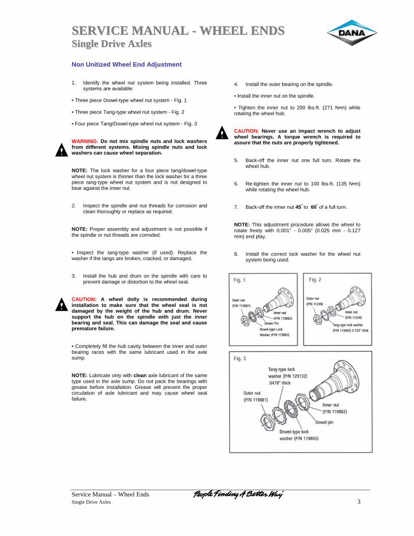
SSEERRVVIICCEE MMAANNUUAALL -- WWHHEEEELL EENNDDSS SSiinnggllee DDrriivvee AAxxlleess
Service Manual – Wheel Ends Single Drive Axles 3
Non Unitized Wheel End Adjustment 1. Identify the wheel nut system being installed. Three
systems are available: • Three piece Dowel-type wheel nut system - Fig. 1 • Three piece Tang-type wheel nut system - Fig. 2 • Four piece Tang/Dowel-type wheel nut system - Fig. 3 WARNING: Do not mix spindle nuts and lock washers from different systems. Mixing spindle nuts and lock washers can cause wheel separation. NOTE: The lock washer for a four piece tang/dowel-type wheel nut system is thinner than the lock washer for a three piece tang-type wheel nut system and is not designed to bear against the inner nut. 2. Inspect the spindle and nut threads for corrosion and
clean thoroughly or replace as required. NOTE: Proper assembly and adjustment is not possible if the spindle or nut threads are corroded. • Inspect the tang-type washer (if used). Replace the washer if the tangs are broken, cracked, or damaged. 3. Install the hub and drum on the spindle with care to
prevent damage or distortion to the wheel seal. CAUTION: A wheel dolly is recommended during installation to make sure that the wheel seal is not damaged by the weight of the hub and drum. Never support the hub on the spindle with just the inner bearing and seal. This can damage the seal and cause premature failure. • Completely fill the hub cavity between the inner and outer bearing races with the same lubricant used in the axle sump. NOTE: Lubricate only with clean axle lubricant of the same type used in the axle sump. Do not pack the bearings with grease before installation. Grease will prevent the proper circulation of axle lubricant and may cause wheel seal failure.
4. Install the outer bearing on the spindle. • Install the inner nut on the spindle. • Tighten the inner nut to 200 lbs-ft. (271 N•m) while rotating the wheel hub. CAUTION: Never use an impact wrench to adjust wheel bearings. A torque wrench is required to assure that the nuts are properly tightened. 5. Back-off the inner nut one full turn. Rotate the
wheel hub. 6. Re-tighten the inner nut to 100 lbs-ft. (135 N•m)
while rotating the wheel hub. 7. Back-off the inner nut 45º to 60º of a full turn. NOTE: This adjustment procedure allows the wheel to rotate freely with 0.001” - 0.005” (0.025 mm - 0.127 mm) end play. 8. Install the correct lock washer for the wheel nut
system being used.
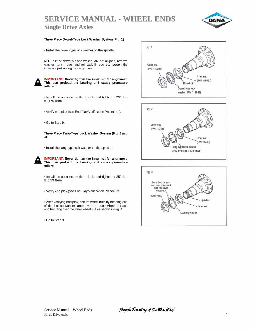
SSEERRVVIICCEE MMAANNUUAALL -- WWHHEEEELL EENNDDSS SSiinnggllee DDrriivvee AAxxlleess
Service Manual – Wheel Ends Single Drive Axles 4
Three Piece Dowel-Type Lock Washer System (Fig. 1) • Install the dowel-type lock washer on the spindle. NOTE: If the dowel pin and washer are not aligned, remove washer, turn it over and reinstall. If required, loosen the inner nut just enough for alignment. IMPORTANT: Never tighten the inner nut for alignment. This can preload the bearing and cause premature failure. • Install the outer nut on the spindle and tighten to 350 lbs-ft. (475 N•m). • Verify end-play (see End Play Verification Procedure). • Go to Step 9. Three Piece Tang-Type Lock Washer System (Fig. 2 and 4) • Install the tang-type lock washer on the spindle. IMPORTANT: Never tighten the inner nut for alignment. This can preload the bearing and cause premature failure. • Install the outer nut on the spindle and tighten to 250 lbs-ft. (339 N•m). • Verify end-play (see End Play Verification Procedure). • After verifying end play, secure wheel nuts by bending one of the locking washer tangs over the outer wheel nut and another tang over the inner wheel nut as shown in Fig. 4. • Go to Step 9.
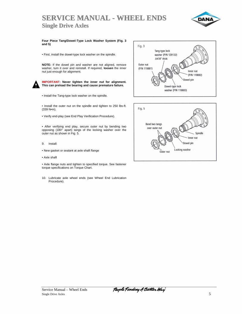
SSEERRVVIICCEE MMAANNUUAALL -- WWHHEEEELL EENNDDSS SSiinnggllee DDrriivvee AAxxlleess
Service Manual – Wheel Ends Single Drive Axles 5
Four Piece Tang/Dowel-Type Lock Washer System (Fig. 3 and 5) • First, install the dowel-type lock washer on the spindle. NOTE: If the dowel pin and washer are not aligned, remove washer, turn it over and reinstall. If required, loosen the inner nut just enough for alignment. IMPORTANT: Never tighten the inner nut for alignment. This can preload the bearing and cause premature failure. • Install the Tang-type lock washer on the spindle. • Install the outer nut on the spindle and tighten to 250 lbs-ft. (339 N•m). • Verify end-play (see End Play Verification Procedure). • After verifying end play, secure outer nut by bending two opposing (180° apart) tangs of the locking washer over the outer nut as shown in Fig. 5. 9. Install: • New gasket or sealant at axle shaft flange • Axle shaft • Axle flange nuts and tighten to specified torque. See fastener torque specifications on Torque Chart. 10. Lubricate axle wheel ends (see Wheel End Lubrication
Procedure).
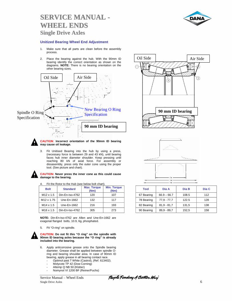
SSEERRVVIICCEE MMAANNUUAALL -- WWHHEEEELL EENNDDSS SSiinnggllee DDrriivvee AAxxlleess
Service Manual – Wheel Ends Single Drive Axles 6
Unitized Bearing Wheel End Adjustment 1. Make sure that all parts are clean before the assembly
process. 2. Place the bearing against the hub. With the 90mm ID
bearing identify the correct orientation as shown on the diagrams. NOTE: There is no bearing orientation on the other bearing sizes.
CAUTION: Incorrect orientation of the 90mm ID bearing may cause oil leakage. 3. Fit Unitised Bearing into the hub by using a press,
(necessary force is between 29 and 43 kN), until bearing faces hub inner diameter shoulder. Keep pressing until reaching 80 kN of axial force. For assembly or dissasembly, press only the outer cone using the proper tool. (See picture and chart).
CAUTION: Never press the inner cone as this could cause damage to the bearing. 4. Fit the Rotor to the Hub (see below bolt chart).
Bolt Standard Max. Torque (Nm)
Min. Torque (Nm)
Tool Dia A Dia B Dia C
M12 x 1.5 Din-En-Iso-4762 120 107 67 Bearing 66.9 – 66.7 108.5 112
M12 x 1.75 Une-En-1662 132 117 78 Bearing 77,9 - 77,7 122.5 128
M14 x 1.5 Une-En-1662 216 193 82 Bearing 81,9 - 81,7 131,5 138
M16 x 1.5 Din-En-Iso-4762 305 273 90 Bearing 89,9 - 89,7 152,5 158
NOTE: Din-En-Iso-4762 are Allen and Une-En-1662 are exagonal flanged bolts, 10.9, 6g, phosphated. 5. Fit “O-ring” on spindle. CAUTION: Do not fit this “O ring” on the spindle with 90mm ID bearing axles because the “O ring” is already included into the bearing. 6. Apply anticorrosive grease onto the Spindle bearing
diameter. Grease shall be applied between spindle O-ring and bearing shoulder area. In case of 90mm ID bearing, apply grease in all bearing contact race. - Optimol past T White (Castrol), (Ref. 613402). - Molycote TP 42 (Dow Corning) - Altemp Q NB 50 (Klüber) - Nomynol VI 1200 BF (Reiner/Fuchs)
Spindle O Ring Specification
New Bearing O Ring Specification
Oil Side Air Side
Oil Side Air Side
90 mm ID bearing
90 mm ID bearing
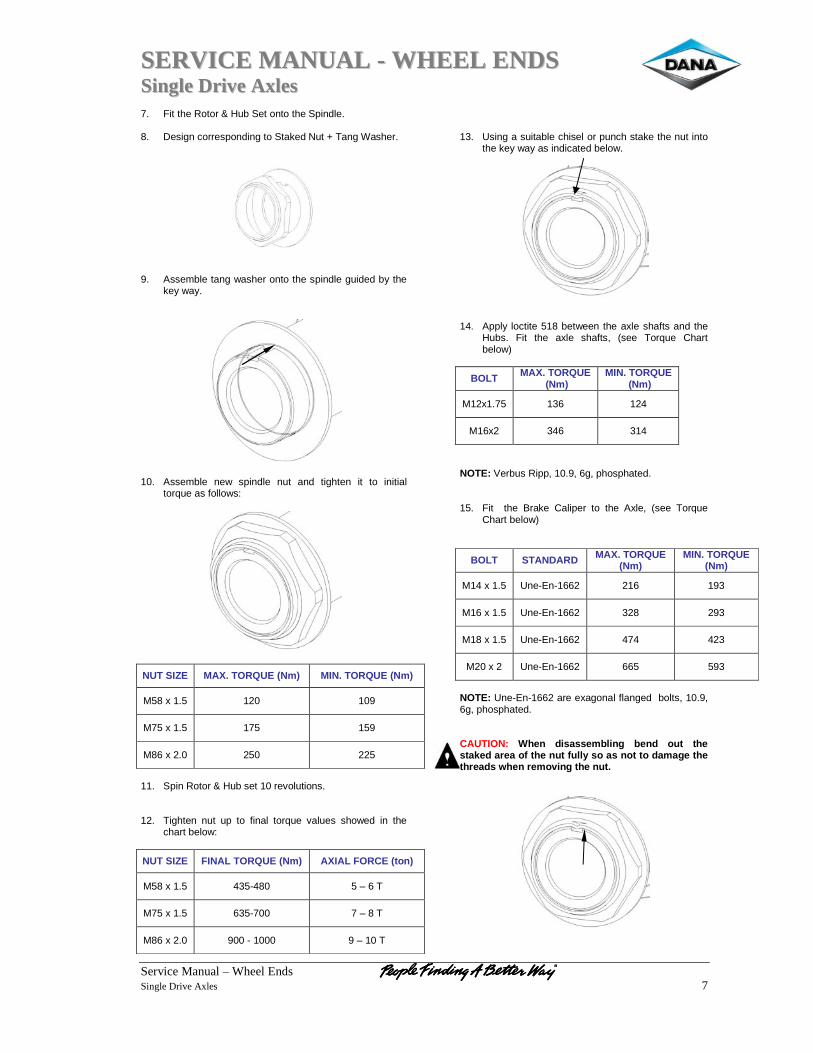
SSEERRVVIICCEE MMAANNUUAALL -- WWHHEEEELL EENNDDSS SSiinnggllee DDrriivvee AAxxlleess
Service Manual – Wheel Ends Single Drive Axles 7
7. Fit the Rotor & Hub Set onto the Spindle. 8. Design corresponding to Staked Nut + Tang Washer.
9. Assemble tang washer onto the spindle guided by the
key way.
10. Assemble new spindle nut and tighten it to initial
torque as follows:
NUT SIZE MAX. TORQUE (Nm) MIN. TORQUE (Nm)
M58 x 1.5 120 109
M75 x 1.5 175 159
M86 x 2.0 250 225
11. Spin Rotor & Hub set 10 revolutions. 12. Tighten nut up to final torque values showed in the
chart below:
NUT SIZE FINAL TORQUE (Nm) AXIAL FORCE (ton)
M58 x 1.5 435-480 5 – 6 T
M75 x 1.5 635-700 7 – 8 T
M86 x 2.0 900 - 1000 9 – 10 T
13. Using a suitable chisel or punch stake the nut into
the key way as indicated below.
14. Apply loctite 518 between the axle shafts and the Hubs. Fit the axle shafts, (see Torque Chart below)
BOLT MAX. TORQUE (Nm)
MIN. TORQUE (Nm)
M12x1.75 136 124
M16x2 346 314
NOTE: Verbus Ripp, 10.9, 6g, phosphated. 15. Fit the Brake Caliper to the Axle, (see Torque
Chart below)
BOLT STANDARD MAX. TORQUE (Nm)
MIN. TORQUE (Nm)
M14 x 1.5 Une-En-1662 216 193
M16 x 1.5 Une-En-1662 328 293
M18 x 1.5 Une-En-1662 474 423
M20 x 2 Une-En-1662 665 593
NOTE: Une-En-1662 are exagonal flanged bolts, 10.9, 6g, phosphated. CAUTION: When disassembling bend out the staked area of the nut fully so as not to damage the threads when removing the nut.
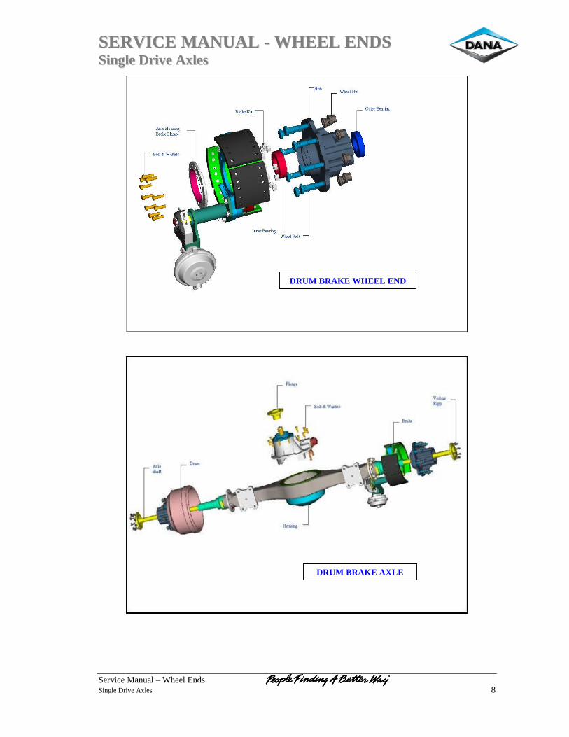
SSEERRVVIICCEE MMAANNUUAALL -- WWHHEEEELL EENNDDSS SSiinnggllee DDrriivvee AAxxlleess
Service Manual – Wheel Ends Single Drive Axles 8
DRUM BRAKE AXLE
DRUM BRAKE WHEEL END
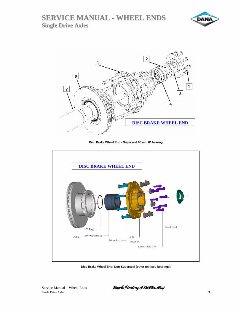
SSEERRVVIICCEE MMAANNUUAALL -- WWHHEEEELL EENNDDSS SSiinnggllee DDrriivvee AAxxlleess
Service Manual – Wheel Ends Single Drive Axles 9
Disc Brake Wheel End - Superseal 90 mm ID bearing
Disc Brake Wheel End: Non-Superseal (other unitised bearings)
DISC BRAKE WHEEL END
DISC BRAKE WHEEL END
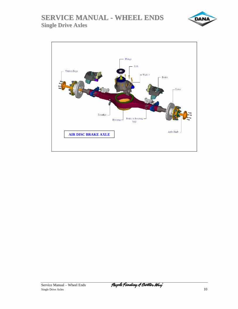
SSEERRVVIICCEE MMAANNUUAALL -- WWHHEEEELL EENNDDSS SSiinnggllee DDrriivvee AAxxlleess
Service Manual – Wheel Ends Single Drive Axles 10
AIR DISC BRAKE AXLE
SSEERRVVIICCEE MMAANNUUAALL -- WWHHEEEELL EENNDDSS SSiinnggllee DDrriivvee AAxxlleess
Service Manual – Wheel Ends Single Drive Axles 11
Dana Corporation / Commercial Vehicle Systems & Speciality – Europe Pamplona Operation / Dana Automoción Polígono Industrial de Landaben, Calle E 31012 Pamplona / Spain TEL (+34-948) 289 100 FAX (+34-948) 281 099 APPLICATION POLICY Capability ratings, features and specifications vary depending upon the model and type of service. Application approvals must be obtained from Dana Spicer Europe Limited. We reserve the right to change or modify our product specifications, configurations, or dimensions at any time without notice.