C o m p o n en ti e sistem i per il fotovoltaico
109
-
Upload
khangminh22 -
Category
Documents
-
view
0 -
download
0
Transcript of C o m p o n en ti e sistem i per il fotovoltaico


Com
pone
nti e
sis
tem
i pe
r il
foto
volt
aico
MNR 52005952/25.05.2010-00 Stampato in Germania © PhoeNix CoNtaCt 2010
tecn
olog
ia d
ella
con
ness
ione
indu
stri
ale,
Si
stem
i di s
igla
tura
e m
ater
iale
per
il m
onta
ggio
Cl
ipl
ine Con
nett
ori i
ndus
tria
li
pl
us
Co
n
Con
ness
ione
per
circ
uiti
st
ampa
ti e
cust
odie
pe
r l’e
lett
roni
ca
Co
mb
iCo
n
Prot
ezio
ne c
ontr
o le
sov
rate
nsio
ni
Tr
ab
Te
Ch
Con
vert
itori
di s
egna
li,
inte
rrut
tori
, alim
enta
tori
inT
er
faC
e
Com
pone
nti e
sis
tem
i
au
To
ma
Tio
n
Per
mag
gior
i inf
orm
azio
ni s
ui p
rodo
tti
pres
enta
ti e
sulle
sol
uzio
ni
Phoe
nix
Con
tact
vis
itat
ew
ww
.pho
enix
cont
act.
it
o c
onta
ttat
eci d
iret
tam
ente
!
Pho
eNix
Co
Nta
Ct
S.p
.a.
2009
5 C
usan
o M
ilani
no (
Mi)
tel:
02 6
6 05
91
Fax:
02
66 0
5 95
00
ww
w.p
hoen
ixco
ntac
t.it
i

2 P
ho
eNix
Co
Nta
Ct
Pho
eNix
Co
Nta
Ct
3
Pho
eNix
Co
Nta
Ct
–vi
cini
ai n
ostr
i clie
nti e
d ai
nos
tri p
artn
er
in t
utto
il m
ondo
Phoe
nix
Con
tact
è le
ader
mon
dial
e ne
lle
solu
zion
i di c
onne
ssio
ne, i
nter
facc
e el
ettr
o-
nich
e e
auto
maz
ione
indu
stri
ale.
La
soci
e-
tà, f
onda
ta p
iù d
i 80
anni
fa, è
com
po-
sta
attu
alm
ente
da
9.90
0 di
pend
enti,
di c
ui o
ltre
5.50
0 so
lo in
Ger
man
ia.
La r
ete
di d
istr
ibuz
ione
, for
mat
a da
oltr
e 46
filia
li e
più
di 3
0 so
ciet
à di
dist
ribu
zion
e, g
aran
tisce
la d
ispo
nibi
lità
dei p
rodo
tti e
dei
ser
vizi
ai c
lient
i dire
tta-
men
te s
ul p
osto
.
La g
amm
a de
i pro
dott
i com
pren
de c
ompo
-
nent
i di e
leva
ta q
ualit
à, s
iste
mi e
ser
vizi
per
le p
iù s
vari
ate
appl
icaz
ioni
. L'o
ffert
a
spaz
ia d
ai m
orse
tti c
ompo
nibi
li al
la t
ecno
lo-
gia
di in
terf
acci
a, a
lla c
onne
ssio
ne p
er c
ircu-
ito s
tam
pato
, a s
oluz
ioni
per
la p
rote
zion
e
cont
ro s
ovra
tens
ioni
fino
a s
iste
mi h
ardw
a-
re e
sof
twar
e pe
r l'a
utom
azio
ne d
i im
pian
ti
indu
stri
ali.
un'
azie
nda
glob
ale
a fi
anco
del
clie
nte
in P
hoen
ix C
onta
ct il
pri
ncip
io d
ell'a
uton
omia
ra
ppre
sent
a un
com
pone
nte
esse
nzia
le d
ella
fil
osof
ia a
zien
dale
che
si t
radu
ce n
ella
sce
lta
di
avva
lers
i di c
ompe
tenz
e e
know
how
inte
rni
all’a
zien
da. N
ell’U
ffici
o te
cnic
o e
nel R
epar
to
di R
icer
ca e
Svi
lupp
o id
ee in
nova
tive
veng
ono
cost
ante
men
te t
rasf
orm
ate
in s
oluz
ioni
cap
aci
di s
oddi
sfar
e le
spe
cific
he e
sige
nze
dei c
lien-
ti. G
li in
num
erev
oli b
reve
tti d
i cui
Pho
enix
C
onta
ct è
tito
lare
dim
ostr
ano
l'ori
gina
lità
di
conc
ezio
ne c
he s
ta a
lla b
ase
delle
mol
tepl
ici
vers
ioni
dei
pro
dott
i svi
lupp
ate.
il fa
bbis
ogno
ene
rget
ico
mon
dial
e co
ntin
ua
ad a
umen
tare
. Dal
pun
to d
i vis
ta e
colo
-gi
co e
d ec
onom
ico,
nel
mix
di f
onti
per
l'app
rovv
igio
nam
ento
ene
rget
ico
l'ene
rgia
ri
gene
rativ
a di
vent
a se
mpr
e pi
ù im
port
ante
. a
ccan
to a
ll'en
ergi
a eo
lica
e id
rica
, alla
bio
-m
assa
e a
l bio
gas,
il fo
tovo
ltai
co r
icop
re u
n gr
ande
ruo
lo.
Gra
zie
alle
futu
re e
sem
pre
mag
gior
i ri
chie
ste,
que
sto
sett
ore
in fo
rte
cres
-ci
ta d
iven
terà
una
col
onna
por
tant
e pe
r l'a
limen
tazi
one
ener
getic
a.
affr
onta
te c
on P
hoen
ix C
onta
ct la
sfid
a pe
r ga
rant
ire
ener
gia
a liv
ello
mon
dial
e.
Da
mol
ti an
ni s
iam
o co
nosc
iuti
nel s
etto
re
per
esse
re p
artn
er a
ffida
bili
e co
mpe
tent
i. a
ttra
vers
o la
nos
tra
espe
rien
za, i
pro
dott
i, le
sol
uzio
ni e
i se
rviz
i con
trib
uiam
o al
fun-
zion
amen
to s
icur
o ed
eco
nom
ico
dei v
ostr
i im
pian
ti.
Gar
anti
re e
nerg
ia p
er il
fut
uro
indi
ce
Com
pone
nti
•Con
nessione
•Morsetticom
ponibili
•Protezionecon
trolesovratensioni
•Dispo
sitiv
idim
isuraecontrollo
Pagi
na 4
sol
uzio
ni d
i sis
tem
a
•Setdiprotezion
econtrolesovratensioni
•Rilevamentodeidatid
ifunzion
amento
•Collegareeautom
atizzare
•Im
piantifotovoltaiciin
dipend
enti Pa
gina
16
acc
esso
ri e
ass
iste
nza
•Sistem
idisiglatura
•So
luzion
isoftw
are
•Utensili
•Serviziodiassistenza
Pagi
na 2
8
lis
te p
rodo
tti
•Tabellediselezionecon
datitecnici
Pagi
na 3
2
Pho
eNix
Co
Nta
Ct
–il
foto
volt
aico
a c
asa.

4 P
ho
eNix
Co
Nta
Ct
Che
sia
te p
rodu
ttor
i di m
odul
i,
impi
antis
ti, p
roge
ttis
ti o
inst
alla
tori
non
ha im
port
anza
, con
l'am
pia
gam
ma
di p
rodo
tti P
hoen
ix C
onta
ct t
rasf
orm
ate
le v
ostr
e si
ngol
e ri
chie
ste
in s
oluz
ioni
foto
volt
aich
e ef
ficac
i.
i com
pone
nti d
i sis
tem
a co
mpa
tibili
e il
nost
ro s
uppo
rto
cont
ribu
isco
no a
ll'el
evat
a
affid
abili
tà d
el v
ostr
o im
pian
to fo
tovo
ltai
co.
Com
pone
nti p
er m
odul
i fot
ovol
taic
i,
scat
ole
di c
onne
ssio
ne e
inve
rter
Pho
eNix
Co
Nta
Ct
5
pag
ina
6 –
7
mod
uli f
otov
olta
ici
•Con
nessioneperm
odulifotovoltaici
•Con
nettorip
ercavifotovoltaici
pag
ina
8 –
13
sca
tole
di c
onne
ssio
ne•Morsetticom
ponibili,fu
sibilieprotezionicon
trole
sovr
aten
sion
i
•Con
vertito
ridicorrente,m
otorstarterecon
trollori
pag
ina
14 –
15
inve
rter
•Passaggiattraversolecustodie
•Con
nessionepercircuitistampati
•Protezionecon
trolesovratensioni
Com
pone
nti e
lett
rote
cnic
iaf
fidab
ili p
er:
am
pie
solu
zion
i di c
ompo
nent
i per
tut
ti i
cam
pi d
el fo
tovo
ltai
co:
mod
uli f
otov
olta
ici
Col
lega
men
ti d
i pot
enza
inse
guit
ori
Trac
ker
Cas
sett
e di
dis
trib
uzio
ne
Con
ness
ioni
di a
ppar
ecch
iatu
re
mon
itor
aggi
o (v
isua
lizza
zion
e)
Con
trol
lo
inve
rter
alim
enta
zion
e

6 P
ho
eNix
Co
Nta
Ct
su
nC
liX
– c
olle
gam
ento
rap
ido
di
mod
uli f
otov
olta
ici
Dur
ante
l'in
stal
lazi
one
di im
pian
ti fo
to-
volt
aici
pot
ete
colle
gare
cav
i di l
ungh
ezza
vari
abile
dal
mod
ulo
all'i
nver
ter,
in m
odo
anco
ra p
iù e
ffica
ce: t
utto
gra
zie
a
SUN
CLi
x.
il co
nnet
tore
SU
NC
Lix
, con
fezi
onab
ile in
cam
po, p
uò e
sser
e in
fatt
i col
lega
to in
mod
o
rapi
do, s
empl
ice
e si
curo
sen
za u
tens
ili s
pe-
cial
i. G
razi
e al
la ju
nctio
n bo
x SU
NC
Lix
,
auto
mat
izza
ta a
l 100
%, è
pos
sibi
le s
empl
i-
ficar
e i p
roce
ssi d
i cre
azio
ne d
el m
odul
o e
ridu
rre
i cos
ti.
Con
ness
ione
per
m
odul
i fot
ovol
taic
i
Pho
eNix
Co
Nta
Ct
7
Junc
tion
box
La s
cato
la d
i der
ivaz
ione
SU
NC
Lix
col
lega
i m
odul
i fot
ovol
taic
i in
mod
o ra
pido
e s
icur
o in
un'
unic
a op
eraz
ione
. È s
tata
stu
diat
a ap
posi
tam
ente
per
mod
uli a
film
sot
tile
o cr
ista
llini
con
cla
sse
di
pote
nza
bass
a. L
a su
a pa
rtic
olar
ità
è il
mon
tagg
io c
ompl
etam
ente
au
tom
atiz
zato
del
la s
cato
la d
i der
ivaz
ione
. N
umer
o di
con
tatt
i: 2
nast
ri e
1 d
iodo
Dis
tanz
a tr
a i c
onta
tti:
20 m
m (
poss
ibili
tà d
i ada
ttam
ento
)D
imen
sion
i del
nas
tro:
fino
a 4
mm
di l
argh
ezza
/0,2
mm
di s
pess
ore
Dia
met
ro e
ster
no c
avo:
5,5
mm
± 0
,2 m
mG
rado
di p
rote
zion
e: iP
65in
bas
e ai
req
uisi
ti de
lla n
orm
a V
VD
e 01
26-5
Cer
tific
azio
ne t
ÜV
Gra
zie
al c
onne
ttor
e SU
NC
Lix
, con
fezi
onab
ile in
cam
po, r
ispa
rmie
-re
te t
empo
e d
enar
o. il
con
nett
ore
vien
e co
nseg
nato
già
mon
tato
. La
conn
essi
one
a m
olla
per
met
te u
na c
onne
ssio
ne r
apid
a e
sem
plic
e in
ca
mpo
sen
za l'
utili
zzo
di u
tens
ili s
peci
ali.
il co
nnet
tore
è c
ompa
tibile
co
n i s
et d
i pro
tezi
one
cont
ro le
sov
rate
nsio
ni P
hoen
ix C
onta
ct e
gli
inve
rter
SM
a.
tens
ione
: 110
0 V
Cor
rent
e: 4
0 a
anc
he c
on 4
mm
²Se
zion
e de
l cav
o: 2
,5 fi
no a
6 m
m²
Gra
do d
i pro
tezi
one:
iP68
Ran
ge d
i tem
pera
tura
: -40
° C
fino
a +
90°
CC
lass
e di
pro
tezi
one:
iiC
ertif
icaz
ione
tÜ
V a
nor
ma
DiN
eN
505
21
il pr
ogra
mm
a SU
NC
Lix
è c
ompl
etat
o da
dis
trib
utor
i a Y
, tre
cav
i so
lari
con
sez
ione
da
2,5,
4 e
6 m
m²
e da
lla r
elat
iva
pinz
a sp
elaf
ili. i
di
stri
buto
ri a
Y e
i ca
vi s
olar
i ven
gono
forn
iti in
rot
oli d
a 10
0 m
etri
ci
ascu
no.
Car
atte
rist
iche
cav
o so
lare
:St
rutt
ura:
fili
sing
oli s
tagn
ati,
isol
amen
to d
oppi
ote
nsio
ne: 1
800
V D
CR
ange
di t
empe
ratu
ra: -
40°
C fi
no a
+90
° C
Col
ore:
ner
oRe
sist
ente
alle
inte
mpe
rie,
ai r
aggi
UV
e a
ll'oz
ono
Con
form
e al
nuo
vo p
rofil
o di
req
uisi
ti D
Ke
2PfG
116
9
Con
nett
ori D
CD
istr
ibut
ori a
Y, c
avi e
ute
nsili
1. P
osiz
iona
re la
junc
tion
box
sul
nast
ro.
2. a
pplic
are
la ju
nctio
n bo
x: i
l nas
tro
si
inse
risc
e au
tom
atic
amen
te.
3. S
ping
ere
la ju
nctio
n bo
x ve
rso
il ba
sso:
il n
astr
o vi
ene
colle
gato
aut
o-m
atic
amen
te e
la ju
nctio
n bo
x si
fis
sa in
mod
o si
curo
.
Le t
abel
le d
i sel
ezio
ne p
er "
Conn
essio
ne d
i mod
uli f
otov
olta
ici e
cab
lagg
io s
ul c
ampo
" si
trov
ano
a pa
gina
33
1. i
ntro
durr
e i c
avi f
otov
olta
ici
sp
elat
i
3. S
erra
re la
vite
:
ecco
fatt
o!n
ota:
sbl
occa
bile
sol
o co
n un
ca
ccia
vite
2. P
rem
ere
sulle
mol
le
e
inse
rire

8 P
ho
eNix
Co
Nta
Ct
rac
cogl
iere
- d
istr
ibui
re -
gar
anti
re
Nel
le s
cato
le d
i con
ness
ione
ven
gono
rac
-
colte
e r
iuni
te le
sin
gole
line
e de
l mod
ulo.
Per
man
tene
re b
assa
la p
erdi
ta d
i pot
enza
la t
ensi
one
dell'
impi
anto
vie
ne m
ante
nuta
rela
tivam
ente
alt
a. L
e te
nsio
ni a
vuo
to fi
no
a 10
00 V
DC
son
o no
rmal
i. Le
ele
vate
ten
-
sion
i DC
impo
ngon
o re
quis
iti p
artic
olar
i ai
com
pone
nti i
nsta
llati.
Gra
zie
alla
ten
sion
e co
ntin
ua p
rese
nte,
dive
rsam
ente
dal
la t
ensi
one
alte
rnat
a su
lla
supe
rfic
ie d
egli
elem
enti
da is
olar
e po
sson
o
form
arsi
pic
cole
tra
cce
supe
rfic
iali.
i co
m-
pone
nti u
tiliz
zati
in q
uest
o ca
mpo
dev
ono
sodd
isfa
re i
requ
isiti
più
ele
vati
in t
erm
ini
di d
ista
nze
in a
ria
e su
perf
icia
li se
cond
o la
norm
a C
ei e
N 6
1730
.
Mor
sett
i com
poni
bili
per
1000
V D
C
Pho
eNix
Co
Nta
Ct
9
mor
sett
i pas
sant
i
i mor
sett
i pas
sant
i pos
sono
ess
e-re
col
lega
ti fr
a lo
ro in
mod
o pr
a-tic
o gr
azie
a p
ontic
elli
a in
nest
o,
risp
arm
iand
o co
sì t
empo
. in
que
sto
mod
o è
poss
ibile
uni
re
in m
odo
effic
ient
e di
vers
e st
rin-
ghe.
mor
sett
i por
tafu
sibi
li
i mor
sett
i por
tafu
sibi
li G
aK
pro
tegg
ono
i cav
i e le
str
ingh
e da
cor
rent
i di g
uast
o el
evat
e e
di r
itorn
o in
cas
o di
cad
uta
della
ten
sion
e o
ombr
eggi
amen
to d
i par
ti de
ll'im
pian
to fo
tovo
ltai
co.
Con
ness
ione
a
mol
lam
orse
tti
ibri
dim
orse
tti
a vi
te
i mor
sett
i pas
sant
i a m
olla
St
si c
arat
teri
z-za
no p
er l'
esec
uzio
ne c
ompa
tta
e l'i
mpi
ego
ottim
ale.
La
forz
a de
i con
tatt
i è in
dipe
nden
te d
all'o
pe-
rato
re. i
con
dutt
ori i
n ra
me
di o
gni t
ipo
fino
a 35
mm
2 po
sson
o es
sere
fiss
ati c
on o
sen
za
punt
alin
i.
i mor
sett
i di c
olle
gam
ento
a b
ullo
ne r
obus
ti so
no d
otat
i di p
erni
di c
olle
gam
ento
fino
a
M8
e po
sson
o al
logg
iare
cap
ocor
da a
d an
ello
co
n un
a se
zion
e m
assi
ma
di 3
5 m
m2 .
N
elle
var
iant
i Rt
il c
olle
gam
ento
del
con
dut-
tore
vie
ne n
otev
olm
ente
faci
litat
o da
l dad
o im
perd
ibile
inte
grat
o.
Con
i m
orse
tti i
brid
i a m
olla
pos
sono
ess
ere
impi
egat
i fin
o a
quat
tro
cond
utto
ri d
a 10
m
m2
su u
n co
ndut
tore
da
35 m
m2 .
L'al
imen
-ta
zion
e av
vien
e m
edia
nte
quat
tro
conn
essi
oni
a m
olla
, il l
ato
d'us
cita
ha
una
conn
essi
one
a vi
te. Q
uatt
ro s
trin
ghe
sing
ole
poss
ono
esse
re
riun
ite c
on u
n so
lo m
orse
tto.
i mor
sett
i sez
iona
tori
con
sent
ono
il se
zion
a-m
ento
di u
n ci
rcui
to s
enza
alle
ntar
e i p
unti
di c
onta
tto.
il p
assa
ggio
può
ess
ere
aper
to o
ch
iuso
med
iant
e un
a sq
uadr
etta
sez
iona
tric
e av
vita
ta. L
o st
ato
di e
serc
izio
vie
ne s
egna
la-
to in
mod
o be
n vi
sibi
le t
ram
ite la
vite
del
la
squa
dret
ta s
ezio
natr
ice
di c
olor
e ar
anci
one.
i mor
sett
i a v
ite s
i con
trad
dist
ingu
ono
per
il co
llega
men
to c
he n
on r
ichi
ede
man
uten
-zi
one,
non
è d
unqu
e ne
cess
ario
un
ulte
rior
e se
rrag
gio
delle
viti
. i c
ondu
ttor
i in
ram
e di
og
ni t
ipo
fino
a 24
0 m
m2
poss
ono
esse
re fi
s-sa
ti co
n o
senz
a pu
ntal
ini.
i mor
sett
i por
tafu
sibi
li al
logg
iano
i fu
sibi
li di
di
men
sion
i 10,
3 m
m x
38
mm
, diff
usis
sim
i nel
fo
tovo
ltai
co.
il Le
D in
tegr
ato
della
ver
sion
e h
eSiL
eD
segn
ala
il fu
sibi
le a
zion
ato.
i f
usib
ili s
i car
atte
rizz
ano
per
una
spec
iale
ca
ratt
eris
tica
gPV
e s
ono
disp
onib
ili n
el r
ange
2
– 20
a.
mor
sett
i di c
olle
gam
ento
a
bullo
nem
orse
tti s
ezio
nato
rim
orse
tti p
orta
fusi
bili
e
fusi
bili
Le t
abel
le d
i sel
ezio
ne p
er "
Mor
sett
i com
poni
bili
– fu
sibili
– ac
cess
ori"
si tr
ovan
o a
pagi
na 4
0

10
Pho
eNix
Co
Nta
Ct
ele
vata
sic
urez
za d
i fun
zion
amen
to p
er
inve
rter
e in
stal
lazi
oni f
otov
olta
iche
La d
ecis
ione
sul
la p
ossi
bile
rea
lizza
zion
e
di u
n im
pian
to fo
tovo
ltai
co s
i bas
a su
lla
valu
tazi
one
della
red
ditiv
ità
e su
l tem
po d
i
amm
orta
men
to d
eriv
ante
. tut
tavi
a sp
esso
non
veng
ono
calc
olat
i i r
isch
i leg
ati a
i ful
mi-
ni.
il fu
nzio
nam
ento
dife
ttos
o no
n pr
evis
to d
i
un in
vert
er a
cau
sa d
i sca
rich
e at
mos
feri
che
può
sign
ifica
re u
n nu
ovo
inve
stim
ento
par
i
fino
al 2
0%
. La
prot
ezio
ne c
ontr
o le
sov
ra-
tens
ioni
com
e m
isur
a pr
even
tiva
aum
enta
l'affi
dabi
lità
dell'
impi
anto
e g
aran
tisce
che
si
otte
nga
il Br
eak
even
Poi
nt p
revi
sto.
Prot
ezio
ne c
ontr
o le
sov
rate
nsio
ni p
er
tens
ioni
DC
e a
C
Pho
eNix
Co
Nta
Ct
11
pro
tezi
one
cont
ro le
sov
rate
nsio
ni
sign
ific
a pr
otez
ione
deg
li in
vest
imen
ti
am
mor
tam
ento
in
cas
o no
rmal
e
Ric
avi
am
mor
tam
ento
in
cas
o di
dan
negg
iam
ento
Ric
avi
sca
rica
tore
di s
ovra
tens
ione
tip
o 2:
Va
lVe
Tr
ab
com
pact
Per
la p
rote
zion
e de
ll'in
vert
er s
ul la
to a
C d
eve
esse
re in
stal
lato
un
o sc
aric
ator
e tip
o 2.
•Esecuzionecom
patta(12mmpercon
duttore)
•Spinadello
scaricatorecon
indicatoredistatooptom
eccanico
•Con
con
tattoFM
liberodapo
tenziale
i di
spos
itiv
i di p
rote
zion
e co
ntro
le s
ovra
-te
nsio
ni V
alV
eT
ra
b o
ffro
no u
na d
oppi
a si
cure
zza
in c
aso
di g
uast
o
i dis
posi
tivi d
i pro
tezi
one
cont
ro le
sov
rate
nsio
-ni
Va
LVet
Ra
B so
no d
otat
i di d
ue s
cari
cato
ri a
va
rist
ore,
ogn
uno
dei q
uali
è in
gra
do d
i por
tare
da
sol
o tu
tta
la t
ensi
one
di s
iste
ma.
L'eq
uipa
ggia
men
to c
on d
ue v
aris
tori
impl
ica
una
dopp
ia s
icur
ezza
di f
unzi
onam
ento
per
l'in
vert
er.
inol
tre
gli s
cari
cato
ri V
aLV
etR
aB-
MS
sodd
isfa
no
già
la fu
tura
dir
ettiv
a pe
r la
pro
tezi
one
degl
i im
pian
ti fo
tovo
ltai
ci.
pro
tezi
one
cont
ro s
ovra
tens
ioni
100
0 V
DC
VaLV
etR
aB-
MS:
Dis
posi
tivi d
i pro
tezi
one
cont
ro le
sov
rate
nsio
ni a
inne
sto
tipo
2, d
ove
le s
ingo
le
spin
e de
llo s
cari
cato
re s
ono
dota
te d
i ind
icat
ore
di s
tato
opt
omec
cani
co.
Con
dizi
oni m
essa
a t
erra
con
ten
sion
e co
ntin
ua (
DC
)
in b
ase
alla
str
uttu
ra d
el s
iste
ma
poss
ono
esse
re im
pieg
ati d
iver
si d
ispo
sitiv
i di p
rote
zion
e co
ntro
le s
ovra
tens
ioni
:
Sist
ema
DC
co
n un
pol
o a
terr
aSi
stem
a D
C
isol
ato
Sist
ema
DC
co
n un
pol
o a
terr
a e
co
n fu
sibi
le
Prot
ezio
ne c
ontr
o le
sov
ra-
tens
ioni
bas
ata
su s
cari
cato
ri a
va
rist
ore
•Asceltaconesenza
cont
atto
FM
libe
ro d
a
po
tenz
iale
•Dispo
nibileanchecom
e
ve
rsio
ne U
psid
e-D
own
(UD
)
Prot
ezio
ne c
ontr
o le
sov
rate
n-si
oni b
asat
a su
spi
nter
omet
ro
•Senzacorrentedid
ispersione
•Asceltaconesenza
cont
atto
FM
libe
ro d
a
po
tenz
iale
Prot
ezio
ne c
ontr
o le
sov
rate
n-si
oni p
er s
iste
mi D
C c
on m
essa
a
terr
a su
un
solo
lato
sen
za
prot
ezio
ne
•Asceltaconesenza
cont
atto
FM
libe
ro d
a
po
tenz
iale
alim
enta
zion
e/
dist
ribu
tore
scar
icat
ore
di c
orre
nte
atm
osfe
rica
tip
o 1:
fla
shT
ra
b c
ompa
ct
i par
aful
min
i nel
le in
stal
lazi
oni f
otov
olta
iche
son
o m
olto
diff
usi.
L'
impi
ego
di d
ispo
sitiv
i di p
rote
zion
e co
ntro
le s
cari
che
atm
osfe
rich
e tip
o 1
è pe
rciò
con
sigl
iato
.
•Scaricatoredienergiaatm
osfericacon
elevata
ca
paci
tà d
i est
inzi
one
di c
orre
nte
suss
egue
nte
•Spinadello
scaricatorecon
indicatoredistatooptom
eccanico
•Con
con
tattoFM
liberodapo
tenziale
2x s
icur
o
Le t
abel
le d
i sel
ezio
ne p
er "
Prot
ezio
ne c
ontr
o le
sov
rate
nsio
ni p
er t
ensio
ni D
C e
AC"
si tr
ovan
o a
pagi
na 4
2
pro
tezi
one
cont
ro le
sov
rate
nsio
ni 2
40/4
15 V
aC

12
Pho
eNix
Co
Nta
Ct
mon
itor
are
dati
car
atte
rist
ici e
con
-
trol
lare
sis
tem
i di i
nseg
uim
ento
Gli
impi
anti
foto
volt
aici
dev
ono
otte
nere
il
mas
sim
o ri
cavo
ene
rget
ico
dalla
cor
rent
e
sola
re n
el m
inor
tem
po p
ossi
bile
. Si t
ratt
a
quin
di d
i rea
gire
dire
ttam
ente
ai g
uast
i del
le
sing
ole
stri
nghe
. il m
onito
ragg
io c
ontin
uo
di t
utti
i dat
i car
atte
rist
ici d
i un
sist
ema
foto
volt
aico
gar
antis
ce il
rile
vam
ento
dire
tto
e qu
indi
rap
ido
degl
i err
ori.
Con
vert
itori
di c
orre
nte,
mot
or s
tart
er
e co
ntro
llori
Pho
eNix
Co
Nta
Ct
13
lun
ga d
urat
a gr
azie
alla
tec
nolo
gia
ibri
da
Rego
lata
da
un m
icro
proc
esso
re, l
a co
mbi
nazi
one
di s
emic
on-
dutt
ori e
sent
i da
usur
a e
di r
obus
ti re
lè g
aran
tisce
un’
attiv
azio
-ne
"pr
otet
ta".
il r
isul
tato
è u
na d
urat
a de
l rel
è st
atic
o tr
ifase
C
oN
taC
tRo
N d
ieci
vol
te s
uper
iore
ris
pett
o al
le a
ppar
ec-
chia
ture
pur
amen
te m
ecca
nich
e. C
oN
taC
tRo
N r
appr
esen
ta
quin
di la
sol
uzio
ne id
eale
per
le fr
eque
nti o
pera
zion
i di c
omm
u-ta
zion
e ne
i sis
tem
i ins
egui
tori
/tra
cker
.
i rel
è st
atic
i tri
fase
Co
Nta
Ct
RoN
ris
parm
iano
spa
zio
e so
no r
apid
i da
cab
lare
. Son
o di
spon
ibili
in c
irca
40
vers
ioni
per
le t
re c
lass
i di
pote
nza
da 0
,6 a
, 2,4
a e
9 a
e c
on t
ensi
oni d
i ing
ress
o da
24
V D
C
o 23
0 V
aC
. i
vant
aggi
:•Fino
al7
5%dispazionecessarioin
meno
•Fino
al7
5%ditem
podicablaggioin
meno
•Durata10
voltesup
eriore
•Unapparecchio,fino
aquattrofu
nzioni
Funz
iona
men
to
dest
rors
o
Funz
iona
men
to
sini
stro
rso
Prot
ezio
ne
mot
ore
arr
esto
d'
emer
genz
a
•Velocitàdie
labo
razion
edi90µsogni1
000istruzioni
•InterfacceIN
TER
BUSeEthernet.
•8kB
fino
a48kB
dim
emoriadatirite
ntivi
•Fino
a409
6pu
ntiI/O
(inbasealtipo)
•Webserver/FT
Pintegrato
•FunzionalitàOPC
•Mod
emG
SM/G
PRSintegrato(in
basealtipo)
rel
è st
atic
o tr
ifase
co
n m
assi
mo
quat
tro
funz
ioni
aut
omaz
ione
sem
plic
e co
nco
ntro
llori
ilC
Con
trol
lo d
i cor
rent
e di
str
ingh
e si
ngol
e
Con
trol
lo d
i cor
rent
e
i con
vert
itori
di c
orre
nte
MC
R t
rasf
orm
ano
corr
enti
cont
inue
e
alte
rnat
e fin
o a
300
a, a
nche
con
cur
ve d
isto
rte,
in s
egna
li an
alog
ici
norm
aliz
zati.
L'a
mpi
o ca
mpo
di a
pplic
azio
ne d
ei c
onve
rtito
ri fa
cilit
a la
rea
lizza
zion
e di
un
cont
rollo
del
la p
oten
za s
enza
lacu
ne n
ei s
iste
mi
foto
volt
aici
.
•Rilevamentodellapotenzadell'impiantoin
dipend
entementedaltipo
di in
vert
er
•Aum
entodell'efficienzaenergeticagraziealrilevamentorapidodegli
erro
ri –
tem
pi d
i fer
mo
rido
tti
•Identificazionedirettadellepotenzem
inimedellesingolestringhe
•Misurazionevaloreefficaceintem
poreale
•Integrazioneneisistemid
imon
itoraggio(Data-Lo
gging,diagnostic
are
mot
a)
Con
vert
itor
i di c
orre
nte
per
cond
utto
ri d
i str
inga
•Elevataprecisionedim
isurazione<0,5%
•Con
nessionepassantefinoaø10
,5m
m•Programmabileecon
figurabile
•Im
postazionecon
tinuarangedim
isure
•Misurazioneverovaloreefficace(TRMS)
•Asceltaconusciterelèetransistor
C
onve
rtit
ori d
i cor
rent
e •Tipid
a10
0A,2
00Ao300
Adispo
nibili
•Elevataprecisionedim
isurazione<1%
•Con
nessionepassantefinoaø30
,5m
m•Misurazioneverovaloreefficace(TRMS)
Con
vert
itor
i di c
orre
nte
– ri
leva
men
to d
ei d
ati c
arat
teri
stic
i fle
ssib
ile
con
cond
utto
ri d
i str
inga
o c
olle
ttor
i
Con
trol
lori
del
la c
lass
e 10
0
Soluzion
iPLC
subaseW
ebcon
unfattorediredditiv
itàelevato:
•Elevataflessibilitàgrazieall'espandibilitàmod
ularecon
mod
uli f
unzi
onal
i e s
tand
ard
del s
iste
ma
i/o in
line
•Semplicitàdiin
tegrazionein
retie
sistentisullabasedi
st
anda
rd in
tern
azio
nali
com
e iN
teR
BUS,
eth
erne
t e
opzi
onal
men
te G
SM/G
PRS
•Scam
biodidaticom
patib
ilem
ediantestandardIT
inte
grat
i com
e h
tt
P, F
tP,
SN
MP,
SQ
L e
oPC
•Programmazionein
tuitivasecon
doIE
C611
31con
il
softwarediautom
azionePCW
orx/PCW
orxEx
press
•Rappo
rtoqu
alità-prezzom
oltobuo
no
Le t
abel
le d
i sel
ezio
ne p
er "
Conv
ertit
ori d
i cor
rent
e", "
Mot
or s
tart
er"
e "C
ontr
ollo
ri" s
i tro
vano
a p
agin
a 36

14
Pho
eNix
Co
Nta
Ct
rob
usti
pas
sagg
i att
rave
rso
le c
usto
die
e co
ntat
to s
icur
o fi
n su
lla s
ched
a
trov
ate
sem
pre
la c
onne
ssio
ne g
iust
a pe
r i
vost
ri d
ispo
sitiv
i: da
lla c
onne
ssio
ne p
er c
ircu-
iti s
tam
pati,
ai p
assa
ggi a
ttra
vers
o le
cus
todi
e
prot
etti
con
iP6x
, fin
o ai
con
nett
ori c
ircol
ari.
Se le
sol
uzio
ni s
tand
ard
non
sono
suf
ficie
nti
svilu
ppia
mo
con
voi l
a vo
stra
con
ness
ione
pers
onal
izza
ta.
Con
ness
ione
di a
ppar
ecch
i
Pho
eNix
Co
Nta
Ct
15
•Morsettie
con
duttorip
erc.s.n
eipassida
2,00
a 7
,62
mm
per
sal
datu
ra a
ond
e, s
alda
tura
ref
low
e
m
onta
ggio
a p
ress
ione
•Con
nettorid
aincassodaM
5aM27
con
con
nessioneasaldareo
fil
i sin
goli
resi
nati
con
grad
o di
pro
tezi
one
iP65
/67
•Con
nettoricon
fezion
abiliin
M8eM12
con
con
nessione
iD
C, a
mol
la, P
ierc
e o
a vi
te c
on g
rado
di p
rote
zion
e iP
65/6
7
•Morsettie
con
duttorip
erc.s.p
erla
te
cnic
a di
ret
e e
la c
omun
icaz
ione
bus
•Con
nettorie
passapareteperRJ45,U
SB,
D
-SU
B e
inte
rfac
ce M
12 c
on g
rado
di p
rote
zion
e iP
65/6
7
•Morsettie
con
duttorip
erc.s.p
erpotenzefino
a125
A
•Con
nettorip
esantididiversedim
ension
iconconn
ession
e
iD
C, a
mol
la, a
vite
e a
cri
mpa
re p
er p
oten
ze fi
no a
200
a c
on
grad
o di
pro
tezi
one
iP65
/67/
69K
Con
ness
ione
di a
ppar
ecch
i –s
iGn
al
Con
ness
ione
di a
ppar
ecch
i –p
oW
er
Con
nett
ore
circ
olar
e M
12
pl
us
Co
n c
ircu
lar
Con
nett
ori p
er c
.s.
– Se
rie
PtPM
Co
mb
iCo
n c
ompa
ct
Con
nettoredatiRJ45
pl
us
Co
n d
ata
Mor
sett
i per
c.s
. –
Seri
e PL
h 1
6
Co
mb
iCo
n p
ower
Con
nett
ori p
er a
ppar
ecch
i m
odul
ari
pl
us
Co
n d
evic
e
Mor
sett
i per
c.s
. –
Seri
e FK
CN
Co
mb
iCo
n c
ontr
ol
Per
un c
olle
gam
ento
affi
dabi
le d
el m
otor
e è
disp
onib
ile u
n pr
ogra
mm
a di
con
nett
ori c
irco
lari
da
M8
a M
58 p
er s
egna
li e
pote
nza.
pro
tezi
one
cont
ro le
sov
rate
nsio
ni t
ipo
3 co
mpa
tto
– pe
r il
mon
tagg
io d
iret
to
nell'
appa
recc
hio
•Perretiisolateconmessaaterra(23
0V,m
onofase)
•Con
nessioniam
olladop
pie(cablaggioaV/T)
•Segnalazioneacusticadelguastointegrata
•Flangedifissaggioperunmon
taggiosem
plice
Le t
abel
le d
i sel
ezio
ne p
er "
Conn
essio
ne p
er d
ispos
itivi
- IP2
0/IP
65/6
7" s
i tro
vano
a p
agin
a 34
Con
ness
ione
di a
ppar
ecch
i –D
aT
a

16
Pho
eNix
Co
Nta
Ct
Gli
impi
anti
foto
volt
aici
ven
gono
con
tinua
-
men
te a
mpl
iati
con
funz
ioni
che
aum
enta
no
cost
ante
men
te la
loro
effi
cien
za. i
l mon
ito-
ragg
io d
ei d
ati c
arat
teri
stic
i con
la c
onte
m-
pora
nea
visu
aliz
zazi
one
di s
tato
è u
n as
pet-
to c
he m
iglio
ra in
mod
o du
revo
le il
ser
vizi
o.
i gra
ndi i
mpi
anti
all'a
pert
o ri
chie
dono
sol
u-
zion
i di g
estio
ne in
telli
gent
i con
sis
tem
i di
cont
rollo
mod
ular
i e s
trut
ture
di r
ete
sca-
labi
li. L
e nu
mer
ose
solu
zion
i di p
rote
zion
e
cont
ro le
sov
rate
nsio
ni g
aran
tisco
no la
mas
sim
a si
cure
zza
di fu
nzio
nam
ento
e
la p
rote
zion
e de
gli i
nves
timen
ti in
un
impi
anto
.
Solu
zion
i di s
iste
ma
per
dive
rsi t
ipi d
i im
pian
ti
Pho
eNix
Co
Nta
Ct
17
Dal
le in
stal
lazi
oni f
otov
olta
iche
sta
ndar
d fin
o ag
li im
pian
ti al
l'ape
rto
pag
ina
18 –
19
sol
uzio
ni s
et p
rote
zion
e co
ntro
le
sovr
aten
sion
iPl
ug’n
’pro
tect
: per
gli
impi
anti
foto
volt
aici
sta
ndar
d i s
et P
V
prec
onfe
zion
ati s
ono
la s
oluz
ione
per
fett
a.
pag
ina
20 –
21
mon
itor
aggi
o e
rile
vam
ento
dei
dat
i di
funz
iona
men
toR
ileva
men
to d
ei d
ati d
i fun
zion
amen
to, m
onito
ragg
io d
i st
ato
e m
anut
enzi
one
a di
stan
za: s
oluz
ioni
di r
ete
per
la
perf
etta
inte
graz
ione
di i
mpi
anti
foto
volt
aici
nel
sis
tem
a di
ge
stio
ne p
er e
dific
i.
pag
ina
22 –
25
Con
trol
lori
e g
esti
one
degl
i im
pian
tiLe
tec
nich
e di
aut
omaz
ione
mod
ular
i per
sen
sori
e
attu
ator
i gar
antis
cono
un'
elev
ata
redd
itivi
tà e
offr
ono
un
a ga
mm
a di
sol
uzio
ni in
divi
dual
i.
pag
ina
26 –
27
impi
anti
fot
ovol
taic
i ind
ipen
dent
i e
sist
emi d
i tra
smis
sion
e ra
dio
i sis
tem
i per
l'al
imen
tazi
one
indi
pend
ente
son
o la
sol
uzio
ne
idea
le p
er a
des
. le
staz
ioni
met
eoro
logi
che.
Le
solu
zion
i w
irel
ess
sono
il c
ompl
etam
ento
rag
ione
vole
per
la t
rasm
is-
sion
e di
dat
i.

4.5.
1.2.
3.
*
18
Pho
eNix
Co
Nta
Ct
Pho
eNix
Co
Nta
Ct
19
La t
abel
la d
i sel
ezio
ne p
er "
Prot
ezio
ne c
ontr
o le
sov
rate
nsio
ni: s
oluz
ioni
set
" si
trov
a a
pagi
na 4
3
Cor
rett
a po
sa in
ope
ra
dei c
ondu
ttor
i
Le lu
nghe
zze
di li
nea
rido
tte
e i c
on-
dutt
ori d
i str
inga
tw
ista
ti di
min
uisc
ono
le in
terf
eren
ze d
i ten
sion
e in
dutt
ive.
È
nece
ssar
io e
vita
re lo
op g
rand
i.
1000
V D
C
pV
-se
T 1
000
DC
1000
V D
C/2
40 V
aC
p
V s
eT
100
0 D
C/a
C60
0 V
DC
p
V s
eT
5s
T/6
00 D
C
Prot
ezio
ne c
ontr
o le
sov
rate
nsio
ni c
on
cust
odia
iP 6
5 pe
r im
pian
ti fo
tovo
ltai
ci
mon
ostr
inga
, con
ness
ione
med
iant
e co
nnet
-to
re m
asch
io/fe
mm
ina
SUN
CLi
x.
1. i
mpi
anto
mon
ostr
inga
2. i
mpi
anto
X-s
trin
g
3. i
mpi
anto
mul
tist
ring
a
Gen
eral
men
te è
nec
es-
sari
o un
PV-
set
o un
o sc
aric
ator
e pe
r di
rezi
o-ne
di c
onne
ssio
ne
(lato
DC
o a
C).
Per
cavi
con
lung
hezz
a a
part
ire
da d
ieci
met
ri
è co
nsig
liabi
le l'
inst
alla
-zi
one
di u
n al
tro
scar
i-ca
tore
.
Prot
ezio
ne c
ontr
o le
sov
rate
nsio
ni, d
ispo
-si
tivo
di a
ttiv
azio
ne g
ener
ator
e e
mor
sett
i co
mpo
nibi
li in
cus
todi
a iP
65, m
assi
mo
cinq
ue
stri
nghe
foto
volt
aich
e.
5. i
mpi
anto
X-s
trin
g
Prot
ezio
ne c
ontr
o le
sov
rate
nsio
ni in
cus
to-
dia
iP65
per
impi
anti
foto
volt
aici
, pro
tezi
one
del l
ato
DC
e a
C d
i un
inve
rter
.
4. p
rote
zion
e D
C/a
C c
ombi
nata
>10m
* Si
stem
i Max
imum
Poi
nt o
f Pow
er
pV
-se
T –
pro
tezi
one
perf
etta
per
inst
alla
zion
i fot
ovol
taic
he
i PV-
Set
pre
conf
ezio
nati
faci
litan
o l'i
nsta
lla-
zion
e di
pro
tezi
oni c
ontr
o le
sov
rate
nsio
ni
negl
i im
pian
ti fo
tovo
ltai
ci. D
iven
tano
par
-
ticol
arm
ente
pra
tici i
n co
mbi
nazi
one
con
i
conn
etto
ri S
UN
CLi
x. i
l PV-
Set
100
0 D
C è
già
dota
to d
elle
rel
ativ
e co
nnes
sion
i.
Prot
ezio
ne c
ontr
o le
sov
rate
nsio
ni in
cu
stod
ie d
i ins
talla
zion
e iP
65 r
obus
te
Dis
tanz
a di
sep
araz
ione
-s-
Dis
tanz
a da
ris
pett
are
tra
l'im
-pi
anto
par
aful
min
e e
i com
pone
nti
dell'
impi
anto
foto
volt
aico
.
pro
tezi
one
cont
ro le
so
vrat
ensi
oni s
ul la
to D
C
i con
dutt
ori d
i str
inga
son
o do
tati
di m
odul
i di p
rote
zion
e co
ntro
le s
ovra
tens
ioni
in
pros
sim
ità
degl
i ing
ress
i deg
li ed
ifici
.
<10m
>10m
>10m
>10m
>10m
>10m
Com
plet
amen
to d
el c
once
tto
di p
rote
-zi
one
anc
he le
inte
rfac
ce d
i dat
i e c
omun
icaz
ione
di
inve
rter
util
izza
te p
er il
rile
vam
ento
di
val
ori d
i mis
ura
devo
no e
sser
e pr
otet
te
con
idon
ei m
odul
i di p
rote
zion
e co
ntro
le
sovr
aten
sion
i.
La g
amm
a di
pro
dott
i Dat
atR
aB
offr
e la
pr
otez
ione
ott
imal
e.

**
20
Pho
eNix
Co
Nta
Ct
Con
trol
lori
su
mis
ura:
esp
andi
bili
a
livel
lo m
odul
are
e in
mod
o ec
onom
ico
Con
le d
iver
se v
ersi
oni d
i mod
uli d
el n
ostr
o
sist
ema
inlin
e i/o
, com
e i m
orse
tti p
er
enco
der
incr
emen
tale
o g
li al
tri m
odul
i ana
-
logi
ci, p
otre
te r
ealiz
zare
faci
lmen
te e
da
soli
la v
ostr
a so
luzi
one
foto
volt
aica
.
all'
occo
rren
za, m
onito
rate
e c
oman
date
gli
statid
ell'impiantograzieaWebPanelanche
dire
ttam
ente
sul
pos
to.
Rile
vam
ento
dat
i ene
rget
ici e
di
agno
stic
a di
sta
to
Pho
eNix
Co
Nta
Ct
21
Le t
abel
le d
i sel
ezio
ne p
er "
Cont
rollo
ri e
siste
mi I
O"
si tr
ovan
o a
pagi
na 3
8
Con
trol
lori
mod
uli
d'in
gres
so/u
scit
aC
oman
do e
su
perv
isio
ne
i con
trol
lori
del
la c
lass
e 10
0 so
no i
più
picc
o-li
elem
enti
della
line
a di
sis
tem
i di c
ontr
ollo
di
Pho
enix
Con
tact
. Son
o do
tati
delle
più
m
oder
ne t
ecno
logi
e di
aut
omaz
ione
e it
e
rapp
rese
ntan
o il
nucl
eo d
ella
sol
uzio
ne.
i con
trol
lori
con
sent
ono
un a
ppro
ccio
con
ve-
nien
te a
ll'au
tom
azio
ne.
insi
eme
ai c
ontr
ollo
ri d
ella
cla
sse
100,
gli
impi
anti
foto
volt
aici
pos
sono
ess
ere
com
an-
dati
e m
onito
rati
in m
odo
econ
omic
o gr
azie
aiW
ebPanel.
Per
l'am
plia
men
to d
el c
ontr
ollo
re è
dis
po-
nibi
le u
n va
sto
asso
rtim
ento
di m
odul
i di
ingr
esso
e u
scit
a, n
onch
é di
vers
i mor
sett
i fu
nzio
nali.
Rile
vate
, ad
esem
pio,
tem
pera
ture
, m
asse
e p
osiz
ioni
con
il r
elat
ivo
mod
ulo,
che
è
poss
ibile
affi
anca
re in
mod
o fle
ssib
ile a
l co
ntro
llore
.
Rete
di a
utom
azio
ne
Ethe
rnet
Ethe
rnet
Colle
gam
ento
dat
i dire
tto
ad
es.
SQ
L
Prot
ezio
ne c
on-
tro
le
sovr
aten
sion
i
Brow
ser
Rile
vam
ento
dei
dat
i car
at-
teris
tici c
on c
onve
rtito
ri di
co
rren
te p
er c
ondu
ttor
i di
strin
ga o
col
lett
ori
vede
re p
ag. 1
2
rea
lizza
zion
e se
mpl
ice
graz
ie
a m
odul
i fun
zion
ali s
tand
ard
Gra
zie
all'u
tiliz
zo d
i com
pone
nti d
i aut
omaz
ione
har
dwar
e e
soft
war
e st
anda
rd è
pos
sibi
le r
ileva
re d
ati e
nerg
etic
i sul
lato
te
nsio
ne c
ontin
ua e
sul
lato
ten
sion
e al
tern
ata.
ess
i ven
gono
el
abor
ati e
mem
oriz
zati
per
l'arc
hivi
azio
ne. P
er il
rile
vam
ento
da
ti en
erge
tici a
utom
atiz
zato
son
o di
spon
ibili
com
pone
nti
hard
war
e e
soft
war
e st
anda
rd. Q
uest
e lib
reri
e pe
r gl
i ute
nti
poss
ono
esse
re s
cari
cate
nel
l'e-s
hop.
ric
hied
ere
stat
o e
dati
car
atte
rist
ici
med
iant
e br
owse
r w
eb
i dat
i e lo
sta
to a
ttua
li de
l sis
tem
a po
sson
o es
sere
visualizzatigrazieaunWebPanelcon
unMicroBrowserinte
-gr
ato.
in a
ltern
ativ
a è
poss
ibile
util
izza
re a
nche
PC
tra
dizi
onal
i co
n br
owse
r w
eb.
* i l
oghi
rap
pres
enta
ti so
no m
arch
i reg
istr
ati i
nter
nazi
onal
i dei
pro
prie
tari
nei r
ispe
ttiv
i pae
si.
Z
**
22
Pho
eNix
Co
Nta
Ct
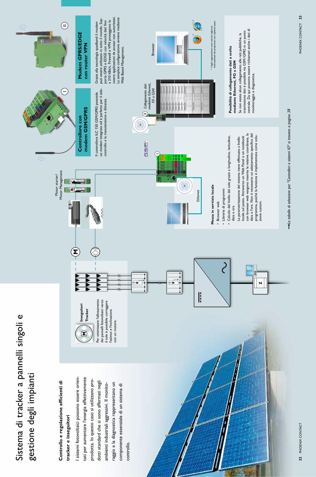
Con
trol
lo e
reg
olaz
ione
eff
icie
nti d
i
trac
ker
e in
segu
itor
i
i sis
tem
i fot
ovol
taic
i pos
sono
ess
ere
orie
n-
tati
per
aum
enta
re l'
ener
gia
effe
ttiv
amen
te
prod
otta
. in
ques
to c
aso
si u
tiliz
zano
pro
-
dott
i sta
ndar
d ch
e si
son
o af
ferm
ati n
egli
ambi
enti
indu
stri
ali a
ggre
ssiv
i. il
mon
ito-
ragg
io e
la d
iagn
ostic
a ra
ppre
sent
ano
un
com
pone
nte
esse
nzia
le d
i un
sist
ema
di
cont
rollo
.
Sist
ema
di t
rack
er a
pan
nelli
sin
goli
e
gest
ione
deg
li im
pian
ti
Pho
eNix
Co
Nta
Ct
23
Le t
abel
le d
i sel
ezio
ne p
er "
Cont
rollo
ri e
siste
mi I
O"
si tr
ovan
o a
pagi
na 3
8
Con
trol
lore
con
m
odem
Gs
m/G
pr
sm
odem
Gp
rs
/eD
Ge
co
n ro
uter
Vp
n
il co
ntro
llore
iLC
150
GSM
/GPR
S po
ssie
de
un m
odem
inte
grat
o ed
è p
erfe
tto
per
il te
le-
cont
rollo
e la
man
uten
zion
e a
dist
anza
.
inse
guit
ori
Trac
ker
Gra
zie
alla
tec
nolo
gia
quad
band
il m
odem
pu
ò es
sere
util
izza
to in
tut
to il
mon
do. S
up-
port
a G
PRS
e eD
Ge
con
velo
cità
dat
i fin
o a
210
kBit/
s. F
irew
all e
VPN
pro
tegg
ono
le
vost
re a
pplic
azio
ni d
a ac
cess
i non
aut
oriz
zati.
La
sem
plic
e co
nfig
uraz
ione
avv
iene
med
iant
e WebBasedM
anagem
ent.
Per
ottim
izza
re l'
allin
eam
ento
de
i pan
nelli
foto
volt
aici
ver
so
il so
le è
pos
sibi
le c
orre
gger
e l'a
zim
ut e
l'in
clin
azio
ne
con
un m
otor
e.
Mot
or s
tart
er/
Mot
or M
anag
emen
t
poss
ibili
tà d
i col
lega
men
to d
ati a
sce
lta
m
edia
nte
eth
erne
t, f
o o
Gs
m
Se n
on e
sist
e al
cun
colle
gam
ento
alle
ret
i pub
blic
he, l
a
tras
mis
sion
e da
ti è
poss
ibile
via
GSM
/GPR
S in
un
punt
o
cent
rale
. Da
qui p
osso
no e
sser
e ri
chia
mat
i anc
he i
dati
di
mon
itora
ggio
e d
iagn
ostic
a.
mes
sa in
ser
vizi
o lo
cale
•Brow
serweb
•Libreriedip
rogram
mi
•Calcolodellivello
delsolegraziealo
ngitu
dine
,latitu
dine
,
data
e o
ra
La
par
amet
rizz
azio
ne d
el s
iste
ma
vien
e ef
fett
uata
a li
vello
localesulposto.A
ttraversounW
ebPanelounno
tebo
ok
con
brow
ser
web
ven
gono
inse
rite
le r
elat
ive
coor
dina
te, l
a da
ta e
l'or
a. N
on è
nec
essa
rio
un a
datt
amen
to s
peci
fico
del
prog
ram
ma,
poi
ché
la fu
nzio
ne è
impl
emen
tata
com
e so
lu-
zion
e cu
stom
.Ethe
rnet
Colle
gam
ento
dat
i m
edia
nte
Ethe
rnet
, F
O o
GSM
Brow
ser
* i l
oghi
rap
pres
enta
ti so
no m
arch
i reg
istr
ati
in
tern
azio
nali
dei p
ropr
ieta
ri n
ei r
ispe
ttiv
i pae
si.
Z

24
Pho
eNix
Co
Nta
Ct
Pho
eNix
Co
Nta
Ct
25
Le t
abel
le d
i sel
ezio
ne p
er "
Tecn
ica
di r
ete"
si t
rova
no a
pag
ina
37
rou
ter
con
fire
wal
lm
anag
ed s
wit
che
ther
net
port
ada
pter
Que
sto
rout
er c
on fi
rew
all i
nteg
rato
cod
ifica
tu
tti i
dat
i sec
ondo
lo s
tand
ard
sicu
ro iP
sec.
in
que
sto
mod
o è
poss
ibile
la m
anut
enzi
one
a di
stan
za s
icur
a e
sem
plic
e di
mac
chin
e e
impi
anti
tram
ite r
eti p
ubbl
iche
. ino
ltre
il ro
u-te
r è
disp
onib
ile a
sce
lta
anch
e co
n tu
nnel
V
PN.
Per
reti
ethe
rnet
ges
tibili
son
o di
spon
ibili
i n
ostr
i Lea
n M
anag
ed S
witc
h. S
uppo
rtan
o st
rutt
ure
di r
ete
rido
ndan
ti co
n di
spos
itivi
di
div
ersi
pro
dutt
ori m
edia
nte
RSt
P e
una
gest
ione
di r
ete
com
plet
a m
edia
nte
SNM
P.
Gli
adat
tato
ri e
ther
net
e Se
rial
Por
t a
dapt
er
Fact
ory
Line
son
o st
ati s
tudi
ati s
peci
ficam
ente
pe
r l'i
mpi
ego
in a
mbi
enti
indu
stri
ali c
ritic
i. es
si
prev
edon
o l'i
nteg
razi
one
faci
le e
d ec
onom
i-ca
di a
ppar
ecch
i di a
utom
azio
ne e
PLC
con
co
llega
men
to s
eria
le o
eth
erne
t in
una
ret
e W
LAN.
sis
tem
a sl
ave
•Diversisistemiapannellisingoliinun
sist
ema
slav
e
•Diversisistemiapannellim
ultip
li
•Com
unicazionedelcon
trollerattraverso
tCP/
iP
•Strutturedidatispecifiche
•Mon
itoraggiolo
cale
•Trasferimentodaticon
array
sp
ecifi
ci/s
trut
ture
m
aste
r s
yste
m
•Sistem
iapannellisingoliconfunzioni
mas
ter
aggi
untiv
e
•Sistem
aapann
ellimultip
liconfunzioni
mas
ter
aggi
untiv
e
•Funzionim
aster
•Calcolodellaposizione
•Con
trollodellatrasm
ission
edatiaglislave
•Com
unicazionealp
arcoserver
•Trasferimentodaticon
arrayspecifici/
stru
ttur
e
esp
andi
bile
su
un s
iste
ma
mul
tipl
o m
aste
r-sl
ave.
Slav
eSl
ave
Slav
e
Slav
eSl
ave
Slav
e
Slav
eM
aste
rSl
ave
Loop
FO
Ethe
rnet
Ethe
rnet
WLA
N
infr
astr
uttu
ra d
i ret
e sc
alab
ile c
on
elev
ata
sicu
rezz
a da
ti
Per
la p
rodu
zion
e ef
ficie
nte
di e
nerg
ia
nei p
arch
i sol
ari s
ono
disp
onib
ili i
sist
emi
mas
ter/
slav
e. o
ltre
allo
sca
mbi
o di
dat
i
sicu
ro e
str
uttu
rato
, ess
i gar
antis
cono
con
-
tem
pora
neam
ente
la r
idon
danz
a de
ll'in
tero
sist
ema.
in q
uant
o un
ità
di c
ontr
ollo
cen
-
tral
e, il
mas
ter
dist
ribu
isce
i da
ti co
rris
pon-
dent
i e t
rasm
ette
le in
form
azio
ni r
acco
lte a
l
cont
rollo
re c
entr
ale.
Sist
ema
di t
rack
er a
pan
nelli
mul
tipli
e
gest
ione
del
par
co

26
Pho
eNix
Co
Nta
Ct
alim
enta
zion
e in
dipe
nden
te
sul c
ampo
i sis
tem
i Sol
ar-S
et R
aD
-So
L-Se
t...
sono
par
ticol
arm
ente
indi
cati
per
alim
en-
tare
ad
esem
pio
staz
ioni
met
eoro
logi
che
o
anch
e pa
rchi
met
ri.
Com
bina
ti co
n so
luzi
oni w
irele
ss o
ffron
o
nuov
e po
ssib
ilità
per
i ri
leva
men
ti in
par
ti di
impi
anto
lont
ane
e di
ffici
lmen
te a
cces
sibi
li.
i sis
tem
i rad
io p
rofe
ssio
nali
devo
no fu
nzio
-
nare
in m
odo
affid
abile
. a s
econ
da d
ell'a
p-
plic
azio
ne s
i son
o af
ferm
ate
le s
egue
nti t
ec-
nolo
gie
di t
rasm
issi
one:
blu
etoo
th –
per
la t
rasm
issi
one
di d
ati d
i
cont
rollo
in c
ondi
zion
i di s
pazi
o lim
itat
o
(aut
omaz
ione
del
le fa
bbri
che)
Wl
an
(ie
ee
802
.11)
– p
er in
fras
trut
-
ture
di r
ete
este
se c
on r
equi
siti
di p
oten
za
elev
ati
Trus
ted
Wir
eles
s –
per
segn
ali p
rivi
di
criti
cità
che
dev
ono
esse
re s
cam
biat
i su
gran
di d
ista
nze
Gsm
/Gp
rs
– sc
ambi
o di
dat
i a li
vello
mon
-
dial
e m
edia
nte
la r
ete
tele
foni
ca m
obile
impi
anti
foto
volt
aici
indi
pend
enti
tras
mis
sion
e ra
dio
di
valo
ri d
i mis
ura
e se
gnal
i
Pho
eNix
Co
Nta
Ct
27
sol
uzio
ni d
i con
trol
lo r
emot
o in
dipe
nden
ti r
aD
-so
l-s
eT.
..
Sono
dis
poni
bili
dive
rsi s
iste
mi R
aD
-So
L-Se
t. a
se
cond
a de
l luo
go d
i ins
talla
zion
e e
dell'
auto
nom
ia
necessaria,è
possibilecollegarecarichifino
a23W
in
mod
o pe
rman
ente
.
i mod
uli f
otov
olta
ici g
ener
ano
la c
orre
nte
suffi
-ci
ente
per
alim
enta
re m
odul
i rad
io, m
odem
GSM
, co
ntro
llori
e c
onve
rtito
ri d
i dat
i di m
isur
azio
ne
dece
ntra
ti o
altr
e un
ità
e pe
r ri
cari
care
la b
atte
ria
sola
re.
forn
itur
a1.
Pan
nello
sol
are
2. S
uppo
rto
per
pann
ello
sol
are
3. Q
uadr
o el
ettr
ico
con
rego
lato
re d
i car
ico
pre-
cabl
ato
4. B
atte
rie
sola
ri5.
Pro
tezi
one
da s
ovra
tens
ioni
6. M
ater
iale
di c
olle
gam
ento
C
ompo
nent
i agg
iunt
ivi
7. a
sta
di fi
ssag
gio
8. D
ispe
rsor
e a
croc
e9.
Sis
tem
a di
tra
smis
sion
e ra
dio
10. a
nten
na r
adio
La t
abel
la d
i sel
ezio
ne p
er "
Impi
anti
foto
volta
ici i
ndi-
pend
enti“
si t
rova
a p
agin
a 36
Wir
eles
s io
Wir
eles
s s
eria
la
cces
sori
wir
eles
s
Con
Wire
lessIO
vengono
trasm
essiin
m
odal
ità
wire
less
seg
nali
anal
ogic
i e d
igit
ali.
ra
D-l
ine
io(TrustedW
ireless)
Mas
sim
a m
odul
arit
à pe
r gr
andi
dis
tanz
e.
ra
D-l
ine
ser
ial i
o(TrustedW
ireless)
Per
un m
assi
mo
di 2
54 m
odul
i in
reti
Mes
h M
odbu
s. C
ome
opzi
one
con
gate
way
Pro
fi-bu
s pe
r l'i
nteg
razi
one
dire
tta
di s
egna
li io
in
Prof
ibus
.
Wir
eles
s m
uX
(Bl
ueto
oth)
tr
aspo
rto
più
rapi
do d
i seg
nali
di c
ontr
ollo
ci
clic
i.
Per
la t
rasm
issi
one
wir
eles
s di
inte
rfac
ce
seri
ali R
S232
, RS4
22 e
RS4
85 v
engo
no
offe
rte
le s
egue
nti l
inee
di p
rodo
tti:
ra
D-l
ine
ser
ial(TrustedW
ireless)
tras
mis
sion
e di
inte
rfac
ce s
eria
li co
n m
assi
-m
o 25
4 ut
enze
.
ps
i-l
ine
blu
etoo
th (
Blue
toot
h)
tras
mis
sion
e di
inte
rfac
ce s
eria
li a
mod
uli d
i co
mun
icaz
ione
che
mut
ano
cost
ante
men
te.
ps
i-m
odem
-lin
e (G
SM/G
PRS)
M
anut
enzi
one
a di
stan
za a
live
llo m
ondi
ale
di im
pian
ti fo
tovo
ltai
ci.
Nel
la m
aggi
or p
arte
dei
cas
i, pe
r il
funz
io-
nam
ento
del
le r
eti w
irel
ess
sono
nec
essa
ri,
oltr
e ai
ver
i e p
ropr
i com
pone
nti,
altr
i ac
cess
ori.
tra
ques
ti ac
cess
ori v
anno
ric
or-
dati
dive
rsi t
ipi d
i ant
enne
, cav
i e a
datt
a-to
ri, s
plitt
er e
dis
posi
tivi p
er la
pro
tezi
one
cont
ro le
sov
rate
nsio
ni c
he n
atur
alm
ente
fa
nno
part
e de
l nos
tro
vast
o as
sort
imen
to
wir
eles
s.
in c
ombi
nazi
one
con
gli i
mpi
anti
foto
volt
aici
indi
pend
enti
o gr
andi
inst
alla
zion
i all'
aper
to, i
mez
zi d
i tra
smis
sion
e w
irel
ess
offr
ono:
•Costidicablaggioem
anutenzion
ebassi
•Semplicesuperamentodio
stacoli
•Espand
ibilitàflessibileerapida
•Integrazionesem
pliceinstruttureesistenti
•Manutenzion
eadistanzain
tuttoilm
ondo
Ulte
riori
info
rmaz
ioni
e d
ati s
ui p
rodo
tti s
ulle
tec
nolo
gie
radi
o in
dust
riali
sono
disp
onib
ili al
l'indi
rizzo
: ww
w.p
hoen
ixco
ntac
t.it

28
Pho
eNix
Co
Nta
Ct
oltr
e al
le s
oluz
ioni
di c
ompo
nent
i e s
iste
-
ma,
Pho
enix
Con
tact
offr
e un
ser
vizi
o di
assi
sten
za p
erso
naliz
zabi
le in
tut
to il
mon
do.
Ma
RK
iNG
sys
tem
è u
n si
stem
a un
iver
sale
Phoe
nix
Con
tact
per
una
sig
latu
ra v
eloc
e e
sem
plic
e de
lle v
ostr
e ap
plic
azio
ni. D
al s
of-
twarediprogettazioneC
LIPPR
OJECT,la
sigl
atur
a vi
ene
tras
mes
sa c
on u
n se
mpl
ice
clic
del
mou
se a
lla s
tam
pant
e e
ques
to in
di-
pend
ente
men
te d
al fa
tto
che
si u
tiliz
zi u
na
stam
pant
e BL
UeM
aR
K L
eD, u
na a
tra
sfer
i-
men
to t
erm
ico
o un
plo
tter
.
Sist
emi d
i sig
latu
ra e
so
luzi
oni s
oftw
are
Pho
eNix
Co
Nta
Ct
29
sof
twar
e di
pro
gett
azio
ne C
lip
pr
oJe
CT
i mor
sett
i com
poni
bili
ed i
com
pone
nti d
i aut
omaz
ione
, int
erfa
ccia
e
prot
ezio
ne c
ontr
o le
sov
rate
nsio
ni p
osso
no e
sser
e pr
oget
tati
in
mod
oancorapiùrapido,sem
pliceepraticoconCLIPPR
OJECT
adva
nced
.
•Programmareeconfezionarein
stallazion
icom
pletesuguide
di s
uppo
rto
dire
ttam
ente
su
com
pute
r
•Anteprima2D
intem
porealecon
possibilitàdim
odificacon
dr
ag’n
’dro
p
•Outpu
tin3Dperilcon
trollodelleprofond
itàdellastruttura
•Num
erosepo
ssibilitàdiimpo
rtazioneedespo
rtazione
,ades.
exce
l, eP
LaN
, ecc
.
•Creazioneditem
plateprop
riegeneratoredicod
iciabarre
(v
ersi
one
prof
essi
onal
e)
La t
abel
la d
i sel
ezio
ne p
er "
Sist
emi d
i sig
latu
ra"
si tr
ova
a pa
gina
36
La t
abel
la d
i sel
ezio
ne p
er "
Solu
zion
i sof
twar
e" s
i tro
va a
pag
ina
39
ma
rK
inG
sys
tem
Com
pone
nti h
ardw
are/
soft
war
e co
mpa
tibili
per
la s
igla
tura
per
fett
a
di m
orse
tti,
cond
utto
ri e
app
arec
chi.
il si
stem
a di
sta
mpa
BLU
eMa
RK
è la
sol
uzio
ne id
eale
per
sch
ede
U
niC
ard
stan
dard
izza
te:
•Capacitàdistampa:1
0.00
0cartelliniall'ora
•Siglaturaresistenteallo
strofinam
entoeaigraffisub
itodop
o
l'out
put
in b
ase
a D
iN e
N 6
1010
-1/V
De
0411
-1
•Lepiùm
odernetecnicheUVegliinchiostrispecialigarantiscono
un'a
sciu
gatu
ra e
colo
gica
sen
za e
mis
sion
e di
sol
vent
i
•L'effettorido
ttodelcaloreproteggeilm
aterialedisup
porto
da d
efor
maz
ioni
o s
colo
rim
enti
•G
razieallatecnicaLED
non
vison
otempidiriscaldam
ento
pro
gram
maz
ione
e v
isua
lizza
zion
e
Per
impi
anti
foto
volt
aici
indu
stri
ali e
in p
artic
olar
e co
n si
stem
i or
ient
ati i
l rile
vam
ento
con
tinuo
dei
dat
i di f
unzi
onam
ento
con
-tr
ibui
sce
note
volm
ente
al m
iglio
ram
ento
del
l'effi
cien
za e
qui
ndi
all'ottimizzazion
edeiricavi.PC
WORXeVisu+
son
oitoo
l so
ftw
are
adat
ti qu
ando
si t
ratt
a di
pro
gram
maz
ione
, par
ame-
triz
zazi
one
e vi
sual
izza
zion
e di
con
trol
lori
.
pC
Wo
rX
è c
ompa
tibile
con
tut
ti i c
ontr
ollo
ri e
mbe
dded
e
basa
ti su
PC
di P
hoen
ix C
onta
ct, è
con
form
e a
ieC
611
31-3
e
disp
one
di u
na c
onfig
uraz
ione
BU
S in
tegr
ata.
Vis
u+ d
ispo
ne d
i un
colle
gam
ento
di c
ontr
ollo
indi
pend
ente
dalp
rodu
ttoremedianteinterfacciaOPC
,idatiP
C-W
orxsono
ut
ilizz
abili
per
la v
isua
lizza
zion
e.

30
Pho
eNix
Co
Nta
Ct
Pho
eNix
Co
Nta
Ct
31
La c
arat
teri
stic
a pr
inci
pale
di u
n ut
ensi
le
prof
essi
onal
e:
è di
vert
ente
usa
rlo
per
lavo
rare
!
Buon
a m
alle
abili
tà e
d er
gono
mia
, lun
ga
dura
ta e
funz
iona
lità
sono
gar
anzi
a di
effi
-
cien
za e
qua
lità
elev
ate.
Que
ste
cara
tter
isti-
che
sono
pre
sent
i in
tutt
i gli
uten
sili
Phoe
nix
Con
tact
.
Per
tutt
i i c
asi l
'ute
nsile
ad
egua
to
ute
nsili
di t
aglio
Cu
Tf
oX
ute
nsili
di s
pela
tura
Wir
ef
oX
pin
ze a
cri
mpa
reC
rim
pf
oX
Per
ogni
rea
ltà
appl
icat
iva
Phoe
nix
Con
tact
of
fre
il ta
glia
cavi
CU
tFo
x o
ttim
ale.
Son
o di
spon
ibili
div
erse
ver
sion
i per
la la
vora
zion
e di
cav
i di v
ari d
iam
etri
.
tutt
e le
par
ti de
l tag
liaca
vi s
otto
post
e a
par-
ticol
ari s
olle
cita
zion
i son
o te
mpr
ate
e bo
nifi-
cate
con
uno
spe
cial
e tr
atta
men
to t
erm
ico.
La v
asta
gam
ma
di p
inze
a c
rim
pare
C
RiM
PFo
x r
appr
esen
ta u
na n
uova
gen
era-
zion
e di
pin
ze a
cri
mpa
re p
rofe
ssio
nali.
Un
nuov
o pr
inci
pio
della
tra
smis
sion
e de
lla fo
rza
ridu
ce d
el 2
5% la
forz
a m
anua
le in
cas
o di
m
assi
ma
pres
sion
e.
Le o
ttim
ali g
eom
etri
e de
i man
ici f
avor
isco
no
il la
voro
sen
za fa
tica.
il b
locc
aggi
o fo
rzat
o in
tegr
ato
gara
ntis
ce u
na c
rim
patu
ra d
i qua
lità
stab
ile n
el t
empo
e a
ten
uta
di g
as.
Per
ogni
ope
razi
one
di s
pela
tura
, la
gam
ma
WIREFOXoffrelostrum
entoid
eale.L
epinzespelafilidip
recision
eW
IREF
OXdi
Phoe
nix
Con
tact
si c
ontr
addi
stin
guon
o pe
r la
lo
ro e
rgon
omia
e le
spe
cial
i geo
met
rie
sulle
la
me
tem
prat
e.
Le t
abel
le d
i sel
ezio
ne p
er "
Ute
nsili"
si t
rova
no a
pag
ina
43
Serv
izio
di a
ssis
tenz
a
i nos
tri s
peci
alis
ti so
no s
empr
e a
vost
ra
disp
osiz
ione
per
lo s
vilu
ppo,
la p
roge
ttaz
io-
ne e
la c
onve
rsio
ne d
ella
sol
uzio
ne c
he
desi
dera
te.
in c
onsi
dera
zion
e de
lle e
sige
nze
spec
ifich
e
dei s
etto
ri, i
nos
tri e
sper
ti po
ssie
dono
un
ampi
o kn
ow-h
ow t
ecno
logi
co.
Con
vert
ite le
vos
tre
rich
iest
e in
siem
e ai
nost
ri s
peci
alis
ti e
trov
ate
sem
pre
la s
olu-
zion
e ot
timal
e pe
r og
ni fa
se d
el v
ostr
o pr
o-
gett
o.
pro
gett
azio
ne e
for
maz
ione
Già
dur
ante
lo s
vilu
ppo
e la
pro
gett
azio
ne s
iam
o al
vos
tro
fianc
o co
n il
nost
ro k
now
-how
tec
nolo
gico
. ins
iem
e a
voi
elab
oria
mo
la s
oluz
ione
ott
imal
e.
il vo
stro
ref
eren
te p
erso
nale
vi s
uppo
rta
dalla
sce
lta
del p
ro-
dott
o fin
o al
la m
essa
in s
ervi
zio.
Vi o
ffria
mo
un'a
mpi
a ga
mm
a di
cor
si p
er la
qua
lific
azio
ne
indi
vidu
ale
dei v
ostr
i col
labo
rato
ri:
•Corsistand
ardperip
rincipid
elletecno
logieattuali
•Trainingin
dividu
ale:potetestabilirecon
noicon
tenuti,
date
e lu
ogo
del c
orso
in m
odo
dett
aglia
to
•Worksho
pperpiccoligrupp
i:vifo
rniamoinform
azioni
spec
iali
sul p
osto
rel
ativ
e al
pro
gett
o de
lla v
ostr
a ap
plic
a-zi
one
il no
stro
tea
m d
i ass
iste
nza
è a
vost
ra d
ispo
sizi
one
in q
ua-
lunq
ue m
omen
to e
sar
ete
sem
pre
in c
onta
tto
con
un r
efer
en-
te c
ompe
tent
e.
Veni
amo
da v
oi s
e pe
r l'a
mpl
iam
ento
del
l'im
pian
to o
in c
aso
di g
uast
i ave
te b
isog
no d
i un
aiut
o ch
e va
oltr
e l'a
ssis
tenz
a te
lefo
nica
.

32
Pho
eNix
Co
Nta
Ct
Pho
eNix
Co
Nta
Ct
33
List
e pr
odot
ti
con
tabe
lle d
i sel
ezio
nep
rodo
tti a
datt
i per
le v
ostr
e ap
plic
azio
ni f
otov
olta
iche
:
Con
ness
ione
•permod
ulifotovoltaicie
cablaggioin
cam
po .
....
....
....
....
....
....
....
....
.33
•perapparecchi–IP
20 .
....
....
....
....
....
....
....
....
....
....
....
....
....
....
.34
•perapparecchi–IP
65/67
...
....
....
....
....
....
....
....
....
....
....
....
....
...3
5
impi
anti
fot
ovol
taic
i ind
ipen
dent
i ..
....
....
....
....
....
....
....
....
....
.36
sis
tem
i di s
igla
tura
...
....
....
....
....
....
....
....
....
....
....
....
....
....
36
mot
or s
tart
er. .
. . .
. . .
. . .
. . .
. . .
. . .
. . .
. . .
. . .
. . .
. . .
. . .
. . .
. . .
. . .
. . .
. . .
. . .
. . .
. .3
6
Tecn
ica
di r
ete
•compo
nentid
iretewirelessecollegatitram
itecavo
...
....
....
....
....
....
...3
7•comando
esup
ervision
e .
....
....
....
....
....
....
....
....
....
....
....
....
....
..37
mor
sett
i com
poni
bili
– fu
sibi
li –
acce
ssor
i ...
....
....
....
....
....
....
....
40
sol
uzio
ni s
oftw
are
...
....
....
....
....
....
....
....
....
....
....
....
....
....
39
Con
trol
lori
e s
iste
mi i
/o .
....
....
....
....
....
....
....
....
....
....
....
....
38
Con
vert
itor
i di c
orre
nte
...
....
....
....
....
....
....
....
....
....
....
....
..39
pro
tezi
one
cont
ro le
sov
rate
nsio
ni•pertensioniD
CeAC
...
....
....
....
....
....
....
....
....
....
....
....
....
....
...4
2•soluzion
iset
...
....
....
....
....
....
....
....
....
....
....
....
....
....
....
....
....
.43
ute
nsili
...
....
....
....
....
....
....
....
....
....
....
....
....
....
....
....
....
43
Nel
le s
egue
nti l
iste
pro
dott
i tro
vate
com
po-
nent
i sel
ezio
nati
con
le lo
ro c
arat
teri
stic
he
tecn
iche
più
impo
rtan
ti. in
form
azio
ni in
te-
grat
ive
e m
olte
altr
e po
ssib
ili s
oluz
ioni
son
o
disp
onib
ili n
el n
ostr
o ca
talo
go g
ener
ale.
il m
odo
più
rapi
do p
er o
tten
ere
mag
gior
i
info
rmaz
ioni
sul
l'int
era
gam
ma
di p
rodo
tti e
serv
izi d
i Pho
enix
Con
tact
è a
ttra
vers
o
inte
rnet
.
Vis
itat
eci a
ll'in
diri
zzo:
ww
w.p
hoen
ixco
ntac
t.it
tecn
olog
ia d
ella
con
ness
ione
indu
stri
ale,
si
stem
i di s
igla
tura
e m
ater
iale
per
il m
onta
ggio
Cl
ipl
ine
Con
nett
ori e
cav
i ind
ustr
iali
pl
us
Co
n
Con
ness
ione
per
cir
cuiti
sta
mpa
ti,
cust
odie
per
ele
ttro
nica
Co
mb
iCo
n
Qua
lità
di r
ete
e se
gnal
e
Tr
ab
Te
Ch Con
vert
itori
di s
egna
li, in
terr
utto
ri,
alim
enta
tori
inT
er
faC
e
Solu
zion
i ava
nzat
e pe
r l'a
utom
azio
-ne
indu
stri
ale
au
To
ma
Tio
n
Cav
i sol
ari
(cer
tific
ati t
ÜV
)St
rutt
ura:
fili
sing
oli s
tagn
ati,
isol
amen
to d
oppi
o;
tens
ione
: 180
0 V
DC
; ran
ge d
i tem
pera
tura
: -4
0 °C
fino
a +
90 °
C; c
olor
e: n
ero;
res
iste
nte
alle
in
tem
peri
e, a
i rag
gi U
V e
all'
ozon
o; c
onfo
rme
al
nuov
o pr
ofilo
di r
equi
siti
DK
e 2P
fG 1
169
sez
ione
2,5
mm
2 10
0 m
ane
llop
V-1
p-1
00,0
-2,5
17
8769
0
sez
ione
4 m
m2
100
m a
nello
pV
-1p
-100
,0-4
17
8770
0
sez
ione
6 m
m2
100
m a
nello
pV
-1p
-100
,0-6
17
8771
3
Dis
trib
utor
e a
Y
per
inte
rcon
ness
ione
del
mod
ulo
foto
volt
aico
pezz
o si
ngol
o a
inne
sto
pV
-YC
6/ 1
-0,1
2 (-
/++)
17
8772
6
pezz
o si
ngol
o a
inne
sto
pV
-YC
6/ 1
-0,1
2 (+
/--)
17
8773
9
Cili
ndro
del
cav
o 10
0 m
, dira
maz
ione
ogn
i 625
mm
p
V-Y
C 6
/ XX
-0,6
25T-
0,2D
(+)
17
8774
2
Con
nett
ore
su
nC
liX
s
cato
la d
i der
ivaz
ione
su
nC
liX
Des
criz
ione
Con
nett
ore
SUN
CLi
x
per
mod
uli f
otov
olta
ici,
ca
blab
ile in
cam
po
Con
nett
ore
SUN
CLi
x
per
mod
uli f
otov
olta
ici,
ca
blab
ile in
cam
po
Scat
ola
di d
eriv
azio
ne S
UN
CLi
x
(jun
ctio
n bo
x)
per
mod
uli f
otov
olta
ici c
on r
ives
timen
to
sott
ileT
ipo
Cod
. art
. p
V-C
f-s
2,5
-6 (
+)
1774
674
pV
-Cm
-s 2
,5-6
(-)
17
7468
7p
V-J
b 2
,5/ 2
-20
sa
mp
le
17
5859
3
sez
ione
[m
m2 ]
2,5
– 6
2,5
– 6
2,5
Tens
ione
no
min
ale
[V]
1100
(iii
/ 2
)11
00 (
iii /
2)
1000
Co
rren
te n
om
inal
e [a
]40
4010
/sen
za d
iodo
Gra
do d
i pro
tezi
one
iP68
iP68
iP65
Car
atte
rist
iche
Ran
ge d
i tem
pera
tura
: -40
°C
fino
a +
90 °
C,
clas
se d
i pro
tezi
one
ii,
cert
ifica
zion
e t
ÜV
a n
orm
a D
iN e
N 5
0521
Ran
ge d
i tem
pera
tura
: -40
°C
fino
a +
90 °
C,
clas
se d
i pro
tezi
one
ii,
cert
ifica
zion
e t
ÜV
a n
orm
a D
iN e
N 5
0521
2 co
ntat
ti pe
r na
stri
, dio
do o
pzio
nale
, per
di
amet
ro e
ster
no c
avo
5,3
– 5,
7 m
m,
conf
orm
e ai
req
uisi
ti in
bas
e a
V
VD
e 01
26-5
Con
ness
ione
per
mod
uli f
otov
olta
ici e
cab
lagg
io in
cam
po

34
Pho
eNix
Co
Nta
Ct
Pho
eNix
Co
Nta
Ct
35
pl
us
Co
n c
ircu
lar
Con
nett
ori c
ircol
ari p
er
appl
icaz
ioni
sen
sore
/att
uato
re
Des
criz
ione
Con
nett
ore
da in
cass
o M
8
con
cave
tti s
enza
alo
gena
ti,
mon
tagg
io a
nter
iore
Con
nett
ore
da in
cass
o M
12
con
cave
tti s
enza
alo
gena
ti,
mon
tagg
io a
nter
iore
Con
nett
ore
da in
cass
o M
12
per
proc
essi
di s
alda
tura
a o
nde,
bi
com
pone
nte,
mon
tagg
io p
oste
riore
Con
nett
ore
da in
cass
o M
12,
per
proc
essi
di r
eflo
w, b
icom
po-
nent
e, m
onta
ggio
pos
teri
ore
Tip
o C
od. a
rt.
sa
CC
-e-m
...
sa
CC
-eC
-...
sa
CC
-Ds
iV-.
..s
aC
C-D
siV
-...
4 po
li m
asch
io...
8ms-
4Co
n-m
8/0,
5
1500
347
...m
s-4C
on
-m16
/0,5
sC
o
1523
463
...m
s-4
Co
n-l
90 s
Co
14
3658
9...
ms-
4Co
n-l
180
sCo
Th
r 1
4399
71
5 po
li m
asch
io...
8ms-
5Co
n-m
8/0
,5 D
n 1
4401
19...
ms-
5Co
n-m
16/0
,5 s
Co
15
2006
8...
ms
-5C
on
-l90
sC
o
1436
602
...m
s-5C
on
-l18
0 sC
o T
hr
155
1752
4 po
li fe
mm
ina
...8f
s-4
Co
n-m
8/0,
5 15
0036
3...
fs-4
Co
n-m
16/0
,5 s
Co
15
2344
7...
fs
-4C
on
-l90
sC
o
1436
564
...fs
-4C
on
-l18
0 sC
o T
hr
143
9997
5 po
li fe
mm
ina
...8f
s-5C
on
-m 8
/0,5
Dn
14
4010
6...
fs-5
Co
n-m
16/0
,5 s
Co
15
2004
2...
fs
-5C
on
-l90
sC
o
1436
563
...fs
-5C
on
-l18
0 sC
o T
hr
154
2622
Tens
ione
di d
imen
sion
amen
to
4/5
poli
30 V
250
V/6
0 V
250
V/6
0 V
250
V/6
0 V
Co
rren
te n
om
inal
e i n
4/5
poli
4 a
/2 a
4 a
/4 a
4 a
/4 a
4 a
/4 a
mat
eria
le in
sert
o p
ort
aco
ntat
tiPU
R/P
a 6
6Pa
66
Pa 6
6Pa
66
mat
eria
le c
ont
atto
/sup
erfi
cie
di c
ont
atto
Lega
Cu/
au
CuZ
n/a
uC
uZn/
au
CuZ
n/a
u
Tip
o di
con
ness
ione
Fili
sing
oli
Fili
sing
oli
Cod
oli
Con
ness
ione
a s
alda
re t
hR
pl
us
Co
n d
ata
Con
nett
ori c
on in
terf
acce
standardcom
eRJ45,U
SBe
M12
per
la t
rasm
issi
one
di d
ati
Des
criz
ione
Insertip
ortacontattifemminaRJ45
e te
lai d
a in
cass
o, p
er s
iste
ma
Free
net
Insertip
ortacontattifemminaRJ45
e te
lai d
a in
cass
o, p
er c
onne
ssio
ne
per
c.s.
inse
rti p
orta
cont
atti
fem
min
a U
SB
e te
lai d
a in
cass
o, p
er c
onne
ssio
ne
flat
cabl
e
Con
nett
ore
da in
cass
o M
12 p
er
proc
essi
di s
alda
tura
a o
nde,
m
onol
itico
inse
rto
port
acon
tatt
i fem
min
a C
at5
Vs
-08-
bu
-rJ4
5-5-
f/p
K
1652
936
Vs
-08-
bu
-rJ4
5/l
p-1
16
8858
6V
s-0
4-b
ua
-fK
-f/i
p67
16
5385
4
inse
rto
po
rtac
ont
atti
fem
min
a C
at6
Vs
-08-
bu
-rJ4
5-6-
f/p
K
1652
949
Vs
-08-
bu
-rJ4
5-6/
lV-1
16
5309
0V
s-0
4-b
ub
-fK
-f/i
p67
16
5386
7
Tela
io d
a in
cass
oV
s-a
-f-i
p67
16
5374
4V
s-08
-a-r
J45/
lp-1
-ip
67
1689
446
Vs
-a-f
-ip
67
1653
744
sa
CC
-Ds
i-...
Co
nnet
tore
da
inca
sso
4
poli,
fem
min
a...
fsD
-4C
on
-l18
0 sC
o
1551
503
Con
nett
ore
da in
cass
o 8
poli,
fem
min
a...
fs-8
Co
n-l
180/
sCo
sh
155
3860
Tens
ione
di d
imen
sio
nam
ento
50
V15
0 V
30 V
250
V
Co
rren
te d
i dim
ensi
ona
men
to1
a1,
5 a
1 a
4 a
num
ero
po
li8
84
4/8
poli
mat
eria
le c
ont
atti
Le
ga C
uLe
ga C
uLe
ga C
uC
uZn
Tip
o d
i co
nnes
sio
neiD
CC
onne
ssio
ne a
sal
dare
Con
ness
ione
flat
cab
leC
odol
i
pl
us
Co
n d
evic
eSi
stem
a di
con
nett
ori m
odul
are
per
la
tras
mis
sion
e di
seg
nali,
dat
i e p
oten
za
Des
criz
ione
Set
di in
sert
i por
taco
ntat
ti
per
lato
mob
ile, c
on P
e,
conn
essi
one
a vi
te
Set
di in
sert
i por
taco
ntat
ti
per
lato
app
arec
chia
tura
, co
nnes
sion
e a
vite
Cus
todi
a m
obile
in a
llum
inio
pre
s-so
fuso
con
usc
ita
cavo
met
rica
, eM
C c
ompa
tibile
Cus
todi
a m
obile
in p
last
ica,
co
n us
cita
cav
o m
etri
ca
Tip
o C
od. a
rt.
VC
-Tr
...V
C-a
r...
ese
cuzi
one
VC
1
4 po
li...
1/2m
-pe
a-s
22-s
eT
16
0714
3...
1/2m
-s22
-se
T
1607
298
VC
-al
-T1-
Z-m
20-s
15
8359
7V
C-K
-T1-
Z-m
20
1852
935
ese
cuzi
one
VC
2
6 po
li...
2/3m
-pe
a-s
222-
se
T
1607
154
...2/
3m-s
222-
se
T
1607
311
VC
-al
-T2-
Z-m
20-s
15
8363
6V
C-K
-T2-
Z-m
25
1852
948
ese
cuzi
one
VC
3
8 po
li...
3/4m
-pe
a-s
2222
-se
T
1607
167
...3/
4m-s
2222
-se
T
1607
322
VC
-al
-T3-
Z-m
25-s
15
8367
8V
C-K
-T3-
Z-m
25
1852
961
ese
cuzi
one
VC
4
10 p
oli
...4/
5m-p
ea-s
2222
2-se
T
1607
178
...4/
5m-s
2222
2-s
eT
16
0733
5V
C-a
l-T
4-Z
-m25
-s
1583
733
VC
-K-T
4-Z
-m25
18
5297
4
Tens
ione
di d
imen
sion
amen
to
400
V40
0 V
––
Co
rren
te d
i dim
ensi
ona
men
to20
a20
a–
–
num
ero
po
lida
4 a
40
poli
da 4
a 4
0 po
li–
–
mat
eria
le c
ont
atti
C
uZn
CuZ
n–
–
Tip
o d
i co
nnes
sio
neC
onne
ssio
ne a
vite
Con
ness
ione
a v
ite–
–
ult
erio
ri c
onn
etto
ri s
ono
dis
poni
bili
nel c
atal
ogo
pl
us
Co
n o
all'
indi
rizz
o w
ww
.pho
enix
cont
act.
it
Co
mb
iCo
n p
ower
Mor
sett
i per
circ
uiti
stam
pati
e co
n-ne
ttor
i per
l'el
ettr
onic
a di
pot
enza
fin
o a
125
a
Des
criz
ione
Con
nett
ore
co
n co
nnes
sion
e a
vite
fino
a 1
25
a c
on p
asso
da
15 m
m
Con
nett
ore
co
n co
nnes
sion
e a
mol
la p
ush-
in
fino
a 6
mm
²
Mor
sett
o pe
r c.
s. P
ush-
Lock
co
n az
iona
men
to a
leva
fin
o a
16 m
m²
Mor
sett
o pe
r c.
s. p
ush-
in
fino
a 10
mm
²
2 po
lip
C 3
5 h
C /
2-s
Tf
17
6259
2s
pC
5/ 2
-sT
Cl
-7,6
2 17
1848
1p
lh
16/
2-1
0-Z
f
1770
461
sp
T 5
/ 2-h
-7,5
-Zb
17
1919
2
3 po
lip
C 3
5 h
C /
3-s
Tf
17
6260
2s
pC
5/ 3
-sT
Cl
-7,6
2 17
1849
4p
lh
16/
3-1
0-Z
f
1770
474
sp
T 5
/ 3-h
-7,5
-Zb
17
1920
2
4 po
lip
C 3
5 h
C /
4-s
Tf
17
6261
5s
pC
5/ 4
-sT
Cl
-7,6
2 17
1850
4p
lh
16/
4-1
0-Z
f
1770
487
sp
T 5
/ 4-h
-7,5
-Zb
17
1921
5
5 po
lip
C 3
5 h
C /
5-s
Tf
17
6262
8s
pC
5/ 5
-sT
Cl
-7,6
2 17
1851
7p
lh
16/
5-1
0-Z
f
1770
490
sp
T 5
/ 5-h
-7,5
-Zb
17
1922
8
sez
ione
35 m
m²
10 m
m²
16 m
m²
10 m
m²
pas
so
15 m
m
7,62
mm
10
mm
7,
5 m
m
num
ero
poli
2 –
6 2
– 12
2
– 8
2 –
12
Tens
ione
no
min
ale
ieC
/ul
10
00 V
/600
V
1000
V/6
00 V
10
00 V
/600
V
1000
V/6
00 V
Cor
rent
e no
min
ale
ieC
/ul
12
5 a
/115
a
41 a
/35
a
76 a
/su
rich
iest
a 41
a/s
u ri
chie
sta
Co
mb
iCo
n c
ontr
ol/
Co
mb
iCo
n c
ompa
ct
Mor
sett
o pe
r c.
s. e
con
nett
ori
per
la t
rasm
issi
one
di s
egna
li e
dati
nella
tec
nica
MSR
Des
criz
ione
Con
nettoreTW
IN-Bus
con
conn
essi
one
a m
olla
fin
o a
1,5
mm
²
Con
nett
ore
piat
to
con
conn
essi
one
a m
olla
pus
h-in
fin
o a
2,5
mm
²
Con
nett
ore
piat
to
con
conn
essi
one
a m
olla
pus
h-in
fin
o a
1,5
mm
²
Con
nett
ore
inve
rtito
co
n co
nnes
sion
e a
vite
fin
o a
2,5
mm
²
2 po
liT
Vf
KC
1,5
/ 2-s
T
1713
839
fK
Cn
2,5
/ 2-s
T
1732
742
fm
C 1
,5/ 2
-sT-
3,5-
rf
19
5202
1G
iC 2
,5/ 2
-sT
f-7
,62
1858
879
3 po
liT
Vf
KC
1,5
/ 3-s
T
1713
842
fK
Cn
2,5
/ 3-s
T
1732
755
fm
C 1
,5/ 3
-sT-
3,5-
rf
19
5203
4G
iC 2
,5/ 3
-sT
f-7
,62
1858
882
4 po
liT
Vf
KC
1,5
/ 4-s
T
1713
855
fK
Cn
2,5
/ 4-s
T
1732
768
fm
C 1
,5/ 4
-sT-
3,5-
rf
19
5204
7G
iC 2
,5/ 4
-sT
f-7
,62
1858
895
5 po
liT
Vf
KC
1,5
/ 5-s
T
1713
868
fK
Cn
2,5
/ 5-s
T
1732
771
fm
C 1
,5/ 5
-sT-
3,5-
rf
19
5205
0G
iC 2
,5/ 5
-sT
f-7
,62
1858
905
sez
ione
1,5
mm
² 2,
5 m
m²
1,5
mm
² 2,
5 m
m²
pas
so
5,0
mm
5
mm
/5,0
8 m
m
3,5
mm
7,
62 m
m
num
ero
poli
2 –
10
2 –
18
2 –
20
2 –
12
Tens
ione
no
min
ale
ieC
/ul
32
0 V
/250
V
320
V/s
u ri
chie
sta
160
V/1
50 V
63
0 V
/250
V
Cor
rent
e no
min
ale
ieC
/ul
10
a/8
a
12 a
/su
rich
iest
a 8
a/8
a
12 a
/12
a
Co
mb
iCo
n c
ontr
ol/
Co
mb
iCo
n c
ompa
ct
Mor
sett
o pe
r c.
s. e
con
nett
ori
per
la t
rasm
issi
one
di s
egna
li e
dati
nella
tec
nica
MSR
Des
criz
ione
Mor
sett
o pe
r c.
s. a
mol
la
con
incl
inaz
ione
di 4
5°
fino
a 1,
5 m
m²
Mor
sett
o pe
r c.
s. c
on
conn
essi
one
a m
olla
pus
h-in
fin
o a
2,5
mm
²
Spin
a pe
r co
nnet
tore
mas
chio
co
n co
nnes
sion
e do
ppia
a m
olla
Mor
sett
o pe
r c.
s. p
er
appl
icaz
ioni
SM
D
fino
a 0,
5 m
m²
2 po
lis
pT
a 1
,5/ 2
-3,8
1 17
5147
7s
pT
2,5
/ 2-V
-5,0
-eX
17
3249
6p
TD
a 1
,5/ 2
-ph
-3,5
17
2510
7pT
sm 0
,5/ 2
-2,5
-h-s
mD
r
1771
020
3 po
lis
pT
a 1
,5/ 3
-3,8
1 17
5148
0s
pT
2,5
/ 2-V
-5,0
-eX
17
3250
6p
TD
a 1
,5/ 3
-ph
-3,5
17
2512
0pT
sm 0
,5/ 3
-2,5
-h-s
mD
r
1771
033
4 po
lis
pT
a 1
,5/ 4
-3,8
1 17
5149
3s
pT
2,5
/ 2-V
-5,0
-eX
17
3251
9p
TD
a 1
,5/ 4
-ph
-3,5
17
2513
3pT
sm 0
,5/ 4
-2,5
-h-s
mD
r
1771
046
5 po
lis
pT
a 1
,5/ 5
-3,8
1 17
5150
3s
pT
2,5
/ 2-V
-5,0
-eX
17
3252
2p
TD
a 1
,5/ 5
-ph
-3,5
17
2514
6pT
sm 0
,5/ 5
-2,5
-h-s
mD
r
1771
059
sez
ione
1,5
mm
² fin
o a
2,5
mm
², co
n om
olog
azio
ne e
x 1,
5 m
m²
0,5
mm
²
pas
so
3,81
mm
5
mm
3,
5 m
m
2,5
mm
num
ero
poli
2 –
12
2 –
12
2 –
16
2 –
8
Tens
ione
no
min
ale
ieC
/ul
16
0 V
/300
V
176
V/n
essu
na
240
V/1
50 V
16
0 V
/su
rich
iest
a
Cor
rent
e no
min
ale
ieC
/ul
9
a/1
0 a
23
a/n
essu
na
8 a
/10
a
6 a
/su
rich
iest
a
ult
erio
ri c
onn
etto
ri e
pre
se b
ase
sono
dis
poni
bili
nel c
atal
ogo
Co
mb
iCo
n o
all'
indi
rizz
o w
ww
.pho
enix
cont
act.
it
Con
ness
ione
per
dis
posi
tivi
– i
p20
Con
ness
ione
per
dis
posi
tivi
– i
p65
/67

36
Pho
eNix
Co
Nta
Ct
Pho
eNix
Co
Nta
Ct
37
impi
anti
fot
ovol
taic
i ind
ipen
dent
iC
ompo
nent
i di r
ete
wir
eles
s e
colle
gati
tra
mit
e ca
vo
mot
or s
tart
erC
ontr
ollo
e s
uper
visi
one
ma
rK
inG
sys
tem
BL
UeM
aR
K
Tip
o C
od. a
rt.
bl
ue
ma
rK
le
D
5147
888
blu
ema
rK
flu
iD-C
arT
riD
Ge
5147
421
Des
criz
ione
Stam
pant
e co
n te
cnol
ogia
LeD
-UV,
incl
. cav
o di
ret
e (e
U/U
S), c
avo
USB
, dr
iver
sta
mpa
nte,
man
uale
mul
tilin
gue,
softwarediprogettazioneedisiglatura"CLIPPR
OJECTadvanced"
e un
a ca
rtuc
cia
(30
ml,
inch
iost
ro: n
ero)
Car
tucc
ia in
chio
stro
per
sta
mpa
nte
LeD
BL
UeM
aR
K, 3
0 m
l, in
chio
stro
: ner
o,
suffi
cien
te p
er c
irca
un
mili
one
di c
arat
teri
rel
è st
atic
o tr
ifase
Co
nTa
CT
ro
nRe
lè s
tatic
i tri
fase
per
l'av
viam
ento
e
l'inv
ersi
one
di m
otor
i da
3~ a
C; s
pess
ore
22,5
mm
; du
rata
ele
ttri
ca 3
0 m
ilion
i di c
icli
di m
anov
re;
freq
uenz
a d'
inve
rsio
ne m
ax. 2
hz;
gra
do d
i pro
tezi
one
iP20
Tip
o C
od. a
rt.
elr
-h5-
ies-
sC-2
4DC
/500
aC
-06
2900
582
el
r h
5-i-
sC
-24D
C/5
00a
C-0
,6
2900
573
el
r h
5-i-
sC
-230
aC
/500
aC
-2
2900
575
Tens
ione
d'in
gres
so
24 V
DC
24 V
DC
120/
230
V a
C
Tens
ione
di u
scit
a42
V a
C ..
. 550
V a
C42
V a
C ..
. 550
V a
C42
V a
C ..
. 550
V a
C
Co
rren
te d
i car
ico
max
. 0,6
am
ax. 0
,6 a
max
. 2,4
a
ran
ge t
empe
ratu
re a
mbi
ente
-25
° C
fino
a +
70°
C -
25°
C fi
no a
+70
° C
-25
° C
fino
a +
70°
C
rel
è st
atic
o tr
ifase
Co
nTa
CT
ro
n
Tip
o C
od. a
rt.
el
r h
5-i-
sC
-24D
C/5
00a
C-9
29
0057
6e
lr
h5-
sC
-24D
C/5
00a
C-9
29
0053
8e
lr
h3-
sC
-24D
C/5
00a
C-9
29
0053
0
Tens
ione
d'in
gres
so
24 V
DC
24 V
DC
24 V
DC
Tens
ione
di u
scit
a42
V a
C ..
. 550
V a
C42
V a
C ..
. 550
V a
C42
V a
C ..
. 550
V a
C
Co
rren
te d
i car
ico
max
. 9 a
max
. 9 a
max
. 9 a
ran
ge t
empe
ratu
re a
mbi
ente
-25
° C
fino
a +
70°
C -
25°
C fi
no a
+70
° C
-25
° C
fino
a +
70°
C
set
fot
ovol
taic
i ind
ipen
dent
i
Tip
o C
od. a
rt.
ra
D-s
ol
-se
T-24
-200
29
1772
2r
aD
-so
l-s
eT-
24-1
00
2885
472
ra
D-s
ol
-se
T-12
-10
2917
146
Tens
ione
nom
inal
e24
V D
C24
V D
C12
V D
C
pote
nza
max
.20
0W
p10
0W
p10
Wp
Cap
acit
à de
lle b
atte
rie
100
ah
40 a
h6
ah
Car
ico
max
.
1–23
W(po
tenzadicon
nessionem
ax.
con
cari
co c
osta
nte
tutt
o l'a
nno
in fu
nzio
ne
dell'
auto
nom
ia e
del
luog
o di
util
izzo
)
1–11
W(po
tenzadicon
nessionem
ax.
con
cari
co c
osta
nte
tutt
o l'a
nno
in fu
nzio
ne
dell'
auto
nom
ia e
del
luog
o di
util
izzo
)
0,1–1,2W
(po
tenzadicon
nessionem
ax.
con
cari
co c
osta
nte
tutt
o l'a
nno
in fu
nzio
ne
dell'
auto
nom
ia e
del
luog
o di
util
izzo
)
4 in
1Fu
nzio
nam
ento
de
stro
rso
Funz
iona
men
to s
ini-
stro
rso
arr
esto
d'e
mer
genz
a Pr
otez
ione
mot
ore
3 in
1Fu
nzio
nam
ento
de
stro
rso
Funz
iona
men
to s
ini-
stro
rso
Prot
ezio
ne m
otor
e
2 in
1Fu
nzio
nam
ento
de
stro
rso
Funz
iona
men
to s
ini-
stro
rso
1 in
1Fu
nzio
nam
ento
de
stro
rso
3 in
1Fu
nzio
nam
ento
de
stro
rso
Funz
iona
men
to s
ini-
stro
rso
Prot
ezio
ne m
otor
e
3 in
1Fu
nzio
nam
ento
de
stro
rso
Funz
iona
men
to s
ini-
stro
rso
Prot
ezio
ne m
otor
e
Com
ando
e s
uper
visi
one
Tip
o C
od. a
rt.
Wp
06T
29
1364
5W
p 0
7T/W
s
2700
307
Wp
09T
/Ws
27
0030
9 W
p 1
2T/W
s
2700
306
Dis
play
D
ispl
ay
touc
h sc
reen
6“
tFt
Dis
play
tou
ch
Wide-Screen7“TFT
Dis
play
tou
ch
Wide-Screen9“TFT
Dis
play
tou
ch
Wide-Screen12“TFT
pro
cess
ore
RiS
C a
RM
9 C
PU: 2
00 M
hz
RiS
C a
RM
9 C
PU: 2
00 M
hz
RiS
C a
RM
9 C
PU: 2
00 M
hz
RiS
C a
RM
9 C
PU: 2
00 M
hz
Tem
pera
tura
di u
tiliz
zo0°
C fi
no a
50°
C0°
C fi
no a
50°
C0°
C fi
no a
50°
C0°
C fi
no a
50°
C
Com
pone
nti
di r
ete
wir
eles
s
Tip
o C
od. a
rt.
fl
Wl
an
ap
28
8407
5f
l W
la
n e
pa
2692
791
fl
blu
etoo
th a
p
2737
999
fl
blu
etoo
th e
pa
2692
788
mod
alit
à op
erat
ive
acc
ess
Poin
t, C
lient
Clie
nt
acc
ess
Poin
t, C
lient
C
lient
ant
enna
ante
nne
este
rne
per
2,4
Gh
z o
5Gh
z (c
olle
gam
ento
R-S
Ma
m
asch
io)
ante
nna
spec
iale
inte
grat
a e
a
pola
rizz
azio
ne c
irco
lare
an
tenn
e in
clus
e
(col
lega
men
to S
Ma
fem
min
a)
ante
nna
spec
iale
inte
grat
a e
a
pola
rizz
azio
ne c
irco
lare
sta
ndar
d ie
ee 8
02.1
1 a/
b/g
ieee
802
.11
b/g
Blue
toot
h, c
onfig
urab
ile fi
no a
200
m
(spa
zio
aper
to)
Blue
toot
h, c
onfig
urab
ile fi
no a
200
m
(spa
zio
aper
to)
par
tico
lari
tà
iP65
, alim
enta
zion
e: P
ower
ove
r
ethe
rnet
, 24
V D
CiP
65/
67,
assorbimentodip
otenza<1,1W
att
iP20
, al
imen
tazi
one:
9 V
DC
... 3
0 V
DC
iP 6
5/67
, assorbimentodip
otenza<1,1W
att
Com
pone
nti d
i ret
e
colle
gati
tra
mit
e ca
vo
Tip
o C
od. a
rt.
fl
sw
itch
lm
4T
X/2
fX
28
3265
8f
l n
aT
sm
n 8
TX
29
8936
5f
l m
Gu
ar
D r
s V
pn
29
8961
1f
l m
Gu
ar
D G
T/G
T
2700
197
Des
criz
ione
Man
aged
Sw
itch
co
n du
e po
rte
in fi
bra
di v
etro
Ro
uter
Nat
Rout
er fi
rew
all
Ro
uter
con
fire
wal
l int
ellig
ente
par
tico
lari
tà
Supp
orto
di R
StP,
La
rge
tree
Sup
port
, Fa
st R
ing
Det
ectio
n, V
LaN
Man
aged
Sw
itch
inte
grat
o
con
funz
iona
lità
VPN
, di
spon
ibile
anc
he c
on m
odem
iSD
N
o an
alog
ico
fino
a 20
0 M
Bit/
s di
por
tata
dat
i, G
igab
it-C
onne
ctiv
ity,
slot
SFP
Sta
tefu
l ins
pect
ion
Fire
wal
l pe
r la
mas
sim
a si
cure
zza
e la
mas
sim
a se
mpl
icit
à di
con
figur
azio
ne,
mem
oria
di c
onfig
uraz
ione
inte
r-ca
mbi
abile
sis
tem
i di s
igla
tura
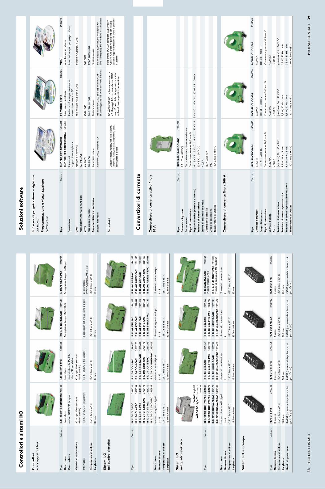
38
Pho
eNix
Co
Nta
Ct
Pho
eNix
Co
Nta
Ct
39
sis
tem
i i/o
ne
l qua
dro
elet
tric
o
Tip
o C
od. a
rt.
ib i
l 2
4 D
i 2-
paC
28
6122
1ib
il
24
Do
2-p
aC
28
6147
0ib
il
ai
2/s
f-p
aC
28
6130
2ib
il
ao
1/s
f-p
aC
28
6131
5
ib i
l 2
4 D
i 4-
paC
28
6123
4ib
il
24
Do
4-p
aC
28
6127
6ib
il
ai
4/e
f-p
aC
28
7844
7ib
il
ao
1/u
/sf
-pa
C
2861
399
ib i
l 2
4 D
i 8-
paC
28
6124
7ib
il
24
Do
8-2
a-p
aC
28
6160
3ib
il
ai
8/s
f-p
aC
28
6141
2ib
il
ao
2/s
f-p
aC
28
6308
3
ib i
l 2
4 D
i 8/
hD
-pa
C
2700
173
ib i
l D
o 8
/hD
-pa
C
2700
172
ib i
l a
i 8/
is-p
aC
28
6166
1ib
il
ao
2/u
/bp
-pa
C
2861
467
ib i
l 2
4 D
i 16
-pa
C
2861
250
ib i
l 2
4 D
o 1
6-pa
C
2861
292
ib i
l a
i 2-
ha
rT-
paC
28
6214
9ib
il
ao
4/8
/u/b
p-p
aC
28
7803
6
ib i
l 2
4 D
i 32
/hD
-pa
C
2862
835
ib i
l 2
4 D
o 3
2/h
D-p
aC
28
6282
2
Des
criz
ione
Mor
sett
i di i
ngre
sso
digi
tali
Mor
sett
i di u
scit
a di
gita
liM
orse
tti d
i ing
ress
o an
alog
ici
Mor
sett
i di u
scit
a an
alog
ici
num
ero
di c
anal
i2
– 32
2 –
322
– 8
1 –
8
Tem
pera
tura
di u
tiliz
zo-2
5° C
fino
a 5
5° C
-25°
C fi
no a
55°
C-2
5° C
fino
a 5
5° C
-25°
C fi
no a
55°
C
lar
ghez
za12
fino
a 4
8 m
m12
fino
a 4
8 m
m12
fino
a 4
8 m
m12
fino
a 4
8 m
m
sis
tem
i i/o
ne
l qua
dro
elet
tric
o
Tip
o C
od. a
rt.
ib il
24/
230
Do
r1/
W-p
aC
286
1881
ib i
l r
s 2
32-p
aC
28
6135
7ib
il
rs
232
-pa
C
2861
357
ib i
l C
an
-ma
-pa
C
2700
196
ib il
24/
230
Do
r4/
W-p
aC
286
1878
ib i
l r
s 2
32-p
ro
-pa
C
2878
722
ib i
l r
s 2
32-p
ro
-pa
C
2878
722
(Mod
ulo
mas
ter
Ca
N)
ib il
24/
230
Do
r1/W
-pC
-pa
C 2
8621
78ib
il
rs
485
/422
-pa
C
2861
933
ib i
l r
s 4
85/4
22-p
aC
28
6193
3ib
il
24 f
lm m
ulT
i-pa
C 2
7370
09
ib il
24/
230
Do
r4/W
-pC
-pa
C 2
8621
81ib
il r
s 48
5/42
2-pr
o-p
aC
286
3627
ib il
rs
485/
422-
pro
-pa
C 2
8636
27(M
odul
o di
der
ivaz
ione
M8
Fiel
dlin
e)
Des
criz
ione
Mor
sett
i di u
scit
a re
lè d
igit
ali
Mor
sett
i di c
omun
icaz
ione
Mor
sett
i di c
omun
icaz
ione
Mor
sett
i di c
omun
icaz
ione
num
ero
di c
anal
i1
– 4
11
1
Tem
pera
tura
di u
tiliz
zo-2
5° C
fino
a 5
5° C
-25°
C fi
no a
55°
C-2
5° C
fino
a 5
5° C
-25°
C fi
no a
55°
C
lar
ghez
za12
fino
a 4
8 m
m12
fino
a 4
8 m
m12
fino
a 4
8 m
m12
mm
sis
tem
i i/o
sul
cam
po
Tip
o C
od. a
rt.
fl
m D
i 8
m8
2773
348
fl
m D
io 8
/4 m
8 27
7335
1f
lm
Do
4 m
8-2a
27
3693
2f
lm
Dio
8 m
8 27
3689
3
num
ero
di c
anal
i8
ingr
essi
8
ingr
essi
4
usci
te8
usci
te
Tem
pera
tura
di u
tiliz
zo-2
5° C
fino
a 6
0° C
-25°
C fi
no a
60°
C-2
5° C
fino
a 6
0° C
-25°
C fi
no a
60°
C
lar
ghez
za29
,8 m
m29
,8 m
m29
,8 m
m29
,8 m
m
Gra
do d
i pro
tezi
one
iP65
/67
(pro
tett
o da
lla p
olve
re e
dai
ge
tti d
'acq
ua)
iP65
/67
(pro
tett
o da
lla p
olve
re e
dai
ge
tti d
'acq
ua)
iP65
/67
(pro
tett
o da
lla p
olve
re e
dai
ge
tti d
'acq
ua)
iP65
/67
(pro
tett
o da
lla p
olve
re e
dai
ge
tti d
'acq
ua)
Con
trol
lori
e
acco
ppia
tori
bus
Tip
o C
od. a
rt.
ilC
150
eT
h G
sm
/Gp
rs
298
5330
ilC
170
eT
h 2
TX
29
1653
2ib
s i
l 2
4 b
K-T
/u-p
aC
28
6158
0il
Ca
n b
K-T
C-p
aC
27
1870
1
Des
criz
ione
Con
trol
lore
Con
trol
lore
acc
oppi
ator
e bu
s pe
r iN
teR
BUS
acc
oppi
ator
e bu
s pe
r C
aN
open
Car
atte
rist
ica
mod
em G
SM/G
PRS
inte
grat
o M
emor
ia f
lash
da
256
MB
(s
ched
a SD
est
raib
ile)
Vel
ocit
à di
ela
bora
zion
e 90
μs
ogni
100
0 is
truz
ioni
(t
ipi d
i dat
i Bit)
90 μ
s og
ni 1
000
istr
uzio
ni
(tip
i di d
ati B
it)
inte
rfac
ce
1 x
iNt
eRBU
S e
1 x
ethe
rnet
1
x iN
teR
BUS
e 2
x et
hern
et
2 co
nnet
tori
sch
erm
ati i
nlin
e a
6 po
li 2x
con
nett
ore
TW
IN-C
OMBICONa5poli
Tem
pera
tura
di u
tiliz
zo-2
5° C
fino
a 5
5° C
-25°
C fi
no a
55°
C-2
5° C
fino
a 5
5° C
-25°
C fi
no a
55°
C
lar
ghez
za80
mm
80 m
m85
mm
85 m
m
...W
-pa
C: a
gSno
2 ...
W-p
C-p
aC
: agS
no2,
dor
atur
a a
spes
sore
sof
twar
e di
pro
gett
azio
ne e
sig
latu
ra
CLIPPR
OJECT
pro
gram
maz
ione
e v
isua
lizza
zion
ePC
Worx,Visu+
Tip
o C
od. a
rt.
Cli
p pr
oJe
CT
aD
Van
CeD
51
4604
0p
C W
or
X D
em
o
2985
725
Vis
u+
2985
770
Cli
p p
ro
JeC
T p
ro
fess
ion
al
5146
053
altr
e lic
enze
su
rich
iest
aa
ltre
licen
ze s
u ri
chie
sta
Des
criz
ione
So
ftw
are
di
prog
etta
zion
e e
sigl
atur
aPa
cche
tto
soft
war
e pe
r so
luzi
oni d
i au
tom
azio
ne b
asat
e su
PC
Lice
nza
di s
vilu
ppo
per
prog
etti
Vis
u+
Cp
uPe
ntiu
m ii
> 4
00M
hz
min
. Pen
tium
4/C
eler
on 1
Gh
zPe
ntiu
m 4
/Cel
eron
, 1 G
hz
mem
ori
a/m
emo
ria
su h
ard
disk
127
MB/
2 G
B–
–
Dri
veC
D-R
oM
DV
D-R
oM
CD
-Ro
M
ris
olu
zio
ne m
oni
tor
1024
x 7
68x
Ga
(10
24 x
768
)SV
Ga
(80
0 x
600)
app
arec
chia
ture
di c
om
ando
Con
sigl
iato
mou
seta
stie
ra, m
ouse
tast
iera
, mou
se
sis
tem
i ope
rati
vi
W
indo
ws20
00,W
indo
wsXP
MSW
indo
ws20
00SP4
,MSW
indo
wsXP
SP2(con
sigliato),MSW
indo
wsVistaBusiness
MSW
indo
ws20
00SP4
,MSW
indo
wsXP
SP2(con
sigliato),MSW
indo
wsVistaBusiness
par
tico
lari
tà
Ling
ue: t
edes
co, i
ngle
se, f
ranc
ese,
ital
iano
, sp
agno
lo, r
usso
, pol
acco
, ung
here
se, c
eco,
po
rtog
hese
e c
ines
e
PCW
ORXBASICcon
licenza,con
tienetutti
e 5
i lin
guag
gi ie
C, c
on c
ompi
lato
re M
SFC
, m
ax. 1
6 by
te d
i dat
i in
ingr
esso
e in
usc
ita,
co
dice
di l
icen
za s
peci
fico
per
vers
ione
Funz
iona
lità
SCa
Da
com
plet
a (S
uper
viso
ry
Con
trol
and
Dat
a a
cqui
sitio
n) c
on v
isua
liz-
zazi
one,
rap
pres
enta
zion
e di
tre
nd e
ges
tione
di
alla
rmi
Con
vert
itor
e di
cor
rent
e at
tivo
fin
o a
50 a
Tip
o C
od. a
rt.
mC
r-s
-10-
50-u
i-D
Ci-
nC
28
1472
8
Cor
rent
e d'
ingr
esso
0 a
... 5
5 a
(a
C/D
C)
form
a cu
rva
Cor
rent
i con
tinue
, alte
rnat
e o
dist
orte
Tip
o d
i co
nnes
sio
neC
onne
ssio
ne p
assa
nte
10,5
mm
Ø
seg
nale
di u
scit
a (n
orm
ale
e in
vers
o)
0 ..
. 5 V
/ 1
... 5
V /
0 ..
. 10
V /
2 ..
. 10
V /
-5
... 5
V /
-10
... 1
0 V
/ 0
... 2
0 m
a /
4 ..
. 20
ma
Tens
ione
di a
limen
tazi
one
20 V
DC
... 3
0 V
DC
err
ore
di t
rasm
issi
one
max
.<0,5%
Co
effi
cien
te t
erm
ico
tip.<
0,025
%/K
Gra
do d
i pro
tezi
one
iP20
Tem
pera
tura
di u
tiliz
zo-2
0° C
fino
a +
60°
C
Con
vert
itor
e di
cor
rent
e fi
no a
300
a
Tip
o C
od. a
rt.
mC
r-s
l-C
uC
-100
-i
23
0802
7m
Cr
-sl
-Cu
C-2
00-i
2308
030
mC
r-s
l-C
uC
-300
-i
23
0804
3
Cor
rent
e d'
ingr
esso
0...1
00 a
0...2
00 a
0...3
00 a
ran
ge d
i fre
quen
zeD
C; 2
0 ...
600
0 h
z D
C; 2
0 ...
600
0 h
z D
C; 2
0 ...
600
0 h
z
Tip
o d
i co
nnes
sio
neC
onne
ssio
ne p
assa
nte
30,5
mm
Ø
Con
ness
ione
pas
sant
e 30
,5 m
m Ø
C
onne
ssio
ne p
assa
nte
30,5
mm
Ø
seg
nale
d'u
scit
a4.
..20
ma
4...2
0 m
a4.
..20
ma
Car
ico
<300
Ω<300
Ω<300
Ω
Tens
ione
di a
limen
tazi
one
(min
./max
.) 20
... 3
0 V
DC
(min
./max
.) 20
... 3
0 V
DC
(min
./max
.) 20
... 3
0 V
DC
Tens
ione
di p
rova
: ing
ress
o/u
scit
a3,
5 kV
, 50
hz,
1 m
in
3,5
kV, 5
0 h
z, 1
min
3,
5 kV
, 50
hz,
1 m
in
Tens
ione
di p
rova
: ing
ress
o/a
limen
tazi
one
3,5
kV, 5
0 h
z, 1
min
3,
5 kV
, 50
hz,
1 m
in
3,5
kV, 5
0 h
z, 1
min
Tem
pera
tura
di u
tiliz
zo-4
0° C
fino
a +
65°
C-4
0° C
fino
a +
65°
C-4
0° C
fino
a +
65°
C
Con
trol
lori
e s
iste
mi i
/os
oluz
ioni
sof
twar
e
Con
vert
itor
i di c
orre
nte

fusi
bili
tens
ione
nom
inal
e 10
00 V
, dim
ensio
ni 1
0,3
x 38
mm
Tip
o C
od. a
rt.
2 a
fu
se
10,
3x38
2a
pV
30
6129
5
4 a
fu
se
10,
3x38
4a
pV
30
6130
5
6 a
fu
se
10,
3x38
6a
pV
30
6131
8
8 a
fu
se
10,
3x38
8a
pV
30
6132
1
10 a
fu
se
10,
3x38
10a
pV
30
6133
4
12 a
fu
se
10,
3x38
12a
pV
30
6134
7
16 a
fu
se
10,
3x38
16a
pV
30
6135
0
20 a
fu
se
10,
3x38
20a
pV
30
6136
3
pia
stra
ter
min
ale
Tip
o C
od. a
rt.
1D
-sT
6
3030
433
2D
-sT
6-T
Win
30
3676
7
3D
-uT
2,5
/10
3047
028
4D
-uT
16
3047
206
5D
-uh
sK
200
0 07
0402
1
6D
-rT
3/5
30
4909
7
7D
-rT
8
3049
194
8D
-rT
5-T
30
4929
1
pont
icel
li2
poli
3 po
li4
poli
5 po
li10
pol
i20
pol
i
Tip
o C
od. a
rt.
Tip
o C
od. a
rt.
Tip
o C
od. a
rt.
Tip
o C
od. a
rt.
Tip
o C
od. a
rt.
Tip
o C
od. a
rt.
1f
bs
2-6
30
3033
6f
bs
3-6
30
3024
2f
bs
4-6
30
3025
5f
bs
5-6
30
3034
9f
bs
10-
6 30
3027
1f
bs
20-
6 30
3036
5
2f
bs
2-8
30
3033
6f
bs
3-8
30
3029
7f
bs
4-8
30
3030
7f
bs
5-8
30
3031
0f
bs
10-
8 30
3032
3–
3f
bs
2-1
0 30
0594
7–
––
––
4f
bs
2-1
2 30
0595
0–
––
––
5f
bs
2-1
6 30
0596
3–
––
––
6f
bi
2-15
02
0133
3f
bi
3-15
02
0127
8–
––
–
7f
bi
2-20
02
0134
6f
bi
3-20
02
0131
7–
––
–
8e
b 2
-25/
uK
h
0201
362
eb
3-2
5/u
Kh
02
0137
5–
––
–
9e
b 2
-31/
uK
h
0201
388
eb
3-3
1/u
Kh
02
0139
1–
––
–
10e
b 2
-36/
uK
h
0201
401
eb
3-3
6/u
Kh
02
0141
4–
––
–
11f
b 1
0-10
-eX
02
0324
7f
b 1
0-10
-eX
02
0324
7f
b 1
0-10
-eX
02
0324
7f
b 1
0-10
-eX
02
0324
7f
b 1
0-10
-eX
02
0324
7–
12e
b 5
6-18
30
0929
9e
b 5
6-18
30
0929
9e
b 5
6-18
30
0929
9e
b 5
6-18
30
0929
9e
b 5
6-18
30
0929
9e
b 5
6-18
30
0929
9
sig
latu
reSc
anal
atur
a ce
ntra
le 1
–7 /
Scan
alat
ura
late
rale
8–1
0
Tip
o C
od. a
rt.
1Z
b 6
: un
pr
inT
eD
10
5100
3
2Z
b 8
: un
pr
inT
eD
10
5200
2
3Z
b 1
0: u
np
rin
Te
D
1053
001
4Z
b 1
2: u
np
rin
Te
D
0812
120
5Z
b 1
6,3:
un
pr
inT
eD
08
2022
2
6Z
b 2
0,3:
un
pr
inT
eD
08
2024
8
7Z
b 2
2: u
np
rin
Te
D
0811
862
8Z
bf
6: u
np
rin
Te
D
0808
710
9Z
bf
8: u
np
rin
Te
D
0808
781
10Z
bf
16:
un
pr
inT
eD
08
2746
4
ute
nsili
Cac
ciav
ite 1
–7 /
Chi
ave
8–12
Tip
o C
od. a
rt.
1s
Zs
0,6
X3,
5 12
0505
3
2s
Zs
1,0
X4,
0 12
0506
6
3s
Zs
1,0
X5,
5 12
0911
4
4s
Zs
1,0
X6,
5 12
0507
9
5s
Zs
1,2
X8,
0 12
0508
2
6s
Zf
2-0
,8X
4,0
1204
520
7s
Zf
3-1
,0X
5,5
1206
612
8V
De
-is
s 6
12
0193
4
9V
De
-is
s 8
12
0194
7
10s
hn
5.5
12
0985
5
11s
hn
8
1209
868
12s
hn
13
1209
923
40
Pho
eNix
Co
Nta
Ct
Pho
eNix
Co
Nta
Ct
41
mor
sett
i com
poni
bili
ieC
ul
Dim
ensi
oni
acc
esso
riG
rigi
o (S
tand
ard)
blu
(B
U)
ros
so
(RD
)Se
zion
e [m
m²]
tens
ione
nom
inal
e [V
]C
orre
nte
nom
inal
e [a
]Se
zion
e [AW
G]
tens
ione
nom
inal
e [V
]C
orre
nte
nom
inal
e [a
]Sp
esso
re/lu
nghe
zza/
altez
za [m
m]
Pont
icel
liSi
glat
ura
Pias
tra
term
inale
atP
Ute
nsili
Tip
o C
od. a
rt.
Tip
o C
od. a
rt.
Tip
o C
od. a
rt.
mor
sett
i a m
olla
sT
6
3031
487
sT
6 b
u
3031
490
–0,
2 –
1010
0052
24 –
860
050
8,2
/ 69
,5 /
43,
52
21
16
sT
35
3036
178
sT
35
bu
30
3618
1 –
2,5
– 35
1000
125
14 –
260
011
516
/ 1
00 /
59
55
––
7
mor
sett
i a t
re c
ondu
ttor
is
T 6
-TW
in
3036
466
sT
6-T
Win
bu
30
3647
9–
0,2
– 10
1000
5224
– 8
600
506,
2 /
47,7
/ 4
7,5
22
2–
6
mor
sett
i ibr
idi
sT
u 3
5/4X
10
3033
126
sT
u 3
5/4X
10 b
u
3033
210
–2,
5 –
35 /
/ 0,
2 –
1010
0012
516
– 1
/0 /
/ 24
– 8
––
16,2
/ 8
6 /
46,8
25
––
7
mor
sett
i a v
ite
uT
uT
4
3044
102
uT
4 b
u
3044
115
uT
4 r
D
3045
127
0,14
– 6
1000
4126
– 1
060
030
6,2
/ 47
,7 /
47,
51
13
11
uT
6
3044
131
uT
6 b
u
3044
144
uT
6 r
D
3045
185
0,2
– 10
1000
5724
– 8
600
508,
2 /
47,7
/ 4
7,5
22
31
2
uT
10
3044
160
uT
10
bu
30
4418
8u
T 1
0 r
D
3046
304
0,5
– 16
1000
7620
– 6
600
6510
,2 /
47,
7 /
47,5
33
31
2
uT
16
3044
199
uT
16
bu
30
4420
9–
1,5
– 25
1000
101
16 –
460
085
12,2
/ 5
5,5
/ 55
44
4–
4
uT
35
3044
225
uT
35
bu
30
4423
8–
1,5
– 50
1000
150
16 –
1/0
600
150
16 /
60,
2 /
65,7
55
––
4
mor
sett
i a v
ite
uK
hu
Kh
25
3009
011
––
4,0
– 25
1000
101
6 –
460
085
15 /
57,
5 /
656
4–
–4
uK
h 5
0 30
0911
8u
Kh
50
bu
30
0910
5u
Kh
50
rD
30
4834
4 16
,0 –
70
1000
150
6 –
1/0
600
150
20 /
70,
5 /
83,5
76
––
5
uK
h 9
5 30
1001
3u
Kh
95
bu
30
1013
6–
25,0
– 9
510
0023
24
– 3/
060
023
025
/ 8
3 /
97,5
87
––
8
uK
h 1
50
3010
110
uK
h 1
50 b
u
3010
123
–35
,0 –
150
1000
309
2 –
300
kcm
il60
028
531
/ 1
00 /
118
,59
7–
–9
uK
h 2
40
3010
217
uK
h 2
40 b
u
0711
852
–70
,0 –
240
1000
415
2/2
– 50
0 kc
mil
600
380
36 /
100
/ 1
31,5
107
––
9
uh
sK
/s 2
000
0704
076
––
0,5
– 10
,010
0057
20 –
810
0050
10,2
/ 5
2 /
70,5
113
5–
2
mor
sett
i di c
olle
gam
ento
a b
ullo
ner
T 3
30
4901
3r
T 3
bu
30
4911
0–
0,1
– 2,
510
0024
26 –
14
600
3012
,3 /
66
/ 51
14
6–
4
rT
5
3049
026
rT
5 b
u
3049
123
–0,
1 –
610
0041
26 –
10
600
3016
,3 /
66
/ 51
25
6–
4
rT
8
3049
042
rT
8 b
u
3049
148
–2,
5 –
3510
0012
514
– 2
600
115
20,3
/ 8
4 /
63,8
36
7–
4
rT
o 3
30
4951
8r
To
3 b
u
3049
660
–0,
1 –
2,5
1000
2426
– 1
460
030
12,3
/ 6
6 /4
9,9
14
6–
10
rT
o 5
30
4952
1r
To
5 b
u
3049
767
–0,
1 –
610
0041
26 –
10
600
3016
,3 /
66
/ 49
,92
56
–11
rT
o 8
30
4934
3r
To
8 b
u
3049
864
–2,
5 –
3510
0012
514
– 2
600
115
20,3
/ 8
4 /
62,2
36
7–
12
mor
sett
i sez
iona
tori
rT
5-T
30
4903
9–
–0,
1 –
610
0041
26 –
10
600
3016
,3 /
91,
4 /
512
58
–4
rT
o 5
-T
3049
233
––
0,1
– 6
1000
4126
– 1
060
030
16,3
/ 9
1,4
/ 59
,92
58
–11
mor
sett
i por
tafu
sibi
liu
K 1
0,3-
he
si
1000
V
3211
236
–1,
5 –
2510
0032
16 –
460
030
17,5
/ 8
1 /
65,5
125
––
1
mor
sett
i por
tafu
sibi
li co
n l
eD
uK
10,
3-h
es
ile
D 1
000V
32
1124
9 –
1,5
– 25
1000
3216
– 4
600
3017
,5 /
81
/ 65
,512
5–
–1
pia
stra
div
isor
ia (
aT
p)
1a
Tp
-sT
6
3024
481
mor
sett
i com
poni
bili
– fu
sibi
li –
acce
ssor
i
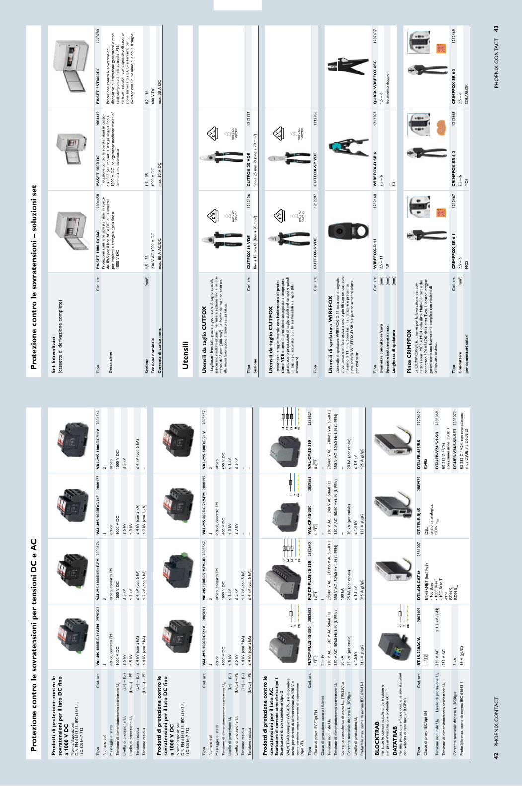
42
Pho
eNix
Co
Nta
Ct
Pho
eNix
Co
Nta
Ct
43
pro
dott
i di p
rote
zion
e co
ntro
le
sovr
aten
sion
i per
il la
to D
C f
ino
a 10
00 V
DC
Nor
me/
disp
osiz
ioni
: D
iN e
N 6
1643
-11,
ieC
616
43-1
, ie
C 6
0364
-7-7
12
Tip
o C
od. a
rt.
Val-
ms
1000
DC
/2+V
-fm
29
2050
2Va
l-m
s 10
00D
C/2
+f-f
m
2800
176
Va
l-m
s 1
000D
C/2
+f
2800
177
Va
l-m
s 1
000D
C/1
+V
2804
542
Num
ero
poli
33
32
Mes
sagg
io d
i sta
toot
tico,
con
tatt
o FM
ottic
o, c
onta
tto
FMot
tico
ottic
o
tens
ione
di d
imen
sion
amen
to s
cari
cato
re U
C10
00 V
DC
1000
V D
C10
00 V
DC
1000
V D
C
Live
llo d
i pro
tezi
one
Up
(L+
) –
(L-)
≤ 5
kV
≤ 5
kV
≤ 5
kV
≤ 5
kV
Live
llo d
i pro
tezi
one
Up
(L+
/L-)
– P
e≤
5 k
V≤
3 k
V≤
3 k
V–
tens
ione
res
idua
(L
+)
– (L
-)≤
4 k
V (
con
5 ka
)≤
4 k
V (
con
5 ka
)≤
4 k
V (
con
5 ka
)≤
4 k
V (
con
5 ka
)
tens
ione
res
idua
(
L+/L
-) –
Pe
≤ 4
kV
(co
n 5
ka)
≤ 2
kV
(co
n 5
ka)
≤ 2
kV
(co
n 5
ka)
–
pro
dott
i di p
rote
zion
e co
ntro
le
sovr
aten
sion
i per
il la
to D
C f
ino
a 10
00 V
DC
Nor
me/
disp
osiz
ioni
: D
iN e
N 6
1643
-11,
ieC
616
43-1
, ie
C 6
0364
-7-7
12
Tip
o C
od. a
rt.
Va
l-m
s 1
000D
C/2
+V
2805
091
Val-
ms
1000
DC
/2+V
-fm
-uD
280
5567
Val-
ms
600D
C/2
+V-f
m 2
8001
95V
al
-ms
600
DC
/2+V
28
0545
7
Num
ero
poli
33
33
Mes
sagg
io d
i sta
toot
tico
ottic
o, c
onta
tto
FMot
tico,
con
tatt
o FM
ottic
o
tens
ione
di d
imen
sion
amen
to s
cari
cato
re U
C10
00 V
DC
1000
V D
C60
0 V
DC
600
V D
C
Live
llo d
i pro
tezi
one
Up
(L+
) –
(L-)
≤ 5
kV
≤ 5
kV
≤ 3
kV
≤ 3
kV
Live
llo d
i pro
tezi
one
Up
(L+
/L-)
– P
e≤
5 k
V≤
5 k
V≤
3 k
V≤
3 k
V
tens
ione
res
idua
(L
+)
– (L
-)≤
4 k
V (
con
5 ka
)≤
4 k
V (
con
5 ka
)–
–
tens
ione
res
idua
(
L+/L
-) –
Pe
≤ 4
kV
(co
n 5
ka)
≤ 4
kV
(co
n 5
ka)
––
pro
dott
i di p
rote
zion
e co
ntro
le
sovr
aten
sion
i per
il la
to a
C
sca
rica
tore
di c
orre
nte
atm
osfe
rica
tip
o 1
sca
rica
tore
di s
ovra
tens
ione
tip
o 2
VaLV
etR
aB
com
pact
(Va
L-C
P-...
) è
disp
onib
ile
anch
e pe
r si
stem
i di a
limen
tazi
one
da 1
20 V
o
com
e ve
rsio
ne s
enza
cor
rent
e di
dis
pers
ione
(t
ipo
VF)
.
Tip
o C
od. a
rt.
flT
-Cp
-pl
us
-1s
-350
28
8268
2f
lT-C
p-p
lu
s-3
s-3
50
2882
640
Va
l-C
p-1
s-3
50
2859
563
Va
l-C
p-3
s-3
50
2859
521
Cla
sse
di p
rova
ieC
/tip
i eN
i /t
1i /
t1
ii /t
2ii
/t2
Cla
sse
di p
rote
zion
e co
ntro
i fu
lmin
iiii
– iV
i–
–
tens
ione
nom
inal
e U
N23
0 V
aC
... 2
40 V
aC
50/
60 h
z23
0/40
0 V
aC ..
. 240
/415
V a
C 5
0/60
hz
230
V a
C ..
. 240
V a
C 5
0/60
hz
230/
400
V aC
... 2
40/4
15 V
aC
50/
60 h
z
tens
ione
di d
imen
sion
amen
to s
cari
cato
re U
C35
0 V
aC
50
/60
hz
L-N
(L-
PeN
)35
0 V
aC
50
/60
hz
L-N
(L-
PeN
)35
0 V
aC
50
/60
hz
L-N
(L-
PeN
)35
0 V
aC
50
/60
hz
L-N
(L-
PeN
)
Cor
rent
e at
mos
feri
ca d
i pro
va i i
mp
(10/
350)
μs50
ka
100
ka–
–
Cor
rent
e no
min
ale
disp
ersa
i n (
8/20
)μs
25 k
a (
per
cana
le)
25 k
a (
per
cana
le)
20 k
a (
per
cana
le)
20 k
a (
per
cana
le)
Live
llo d
i pro
tezi
one
Up
≤ 1
,5 k
V≤
1,5
kV
≤ 1
,4 k
V≤
1,4
kV
Pref
usib
ile m
ax. c
ome
da n
orm
a ie
C 6
1643
-131
5 a
gL/
gG31
5 a
gL/
gG12
5 a
gL/
gG12
5 a
gL/
gG
blo
CK
Tr
ab
Pe
r tu
tte
le c
omun
i sca
tole
di d
eriv
azio
ne e
pe
r pr
ese
d'in
stal
lazi
one
prof
onde
60
mm
.
Da
Ta
Tr
ab
Pe
r un
a pr
otez
ione
effi
cace
con
tro
le s
ovra
tens
ioni
co
n ve
loci
tà d
i ret
e fin
o a
10 G
Bit/
s.
Tip
o C
od. a
rt.
bT-
1s-2
30a
C/a
28
0340
9D
T-l
an
-Ca
T.6+
28
8100
7D
T-T
el
e-r
J45
2882
925
DT-
uf
b-4
85/b
s
2920
612
Cla
sse
di p
rova
ieC
/tip
i eN
iii
/t
3
eth
eRN
et (
incl
. Poe
)
- 10
0 Ba
set
-
1000
Bas
et
- 10
G B
ase
tat
M
iSD
N S
0 iS
DN
S2M
DSL
, te
lefo
nia
anal
ogic
a,
iSD
N U
K0
RS4
85
tens
ione
nom
inal
e U
N
Live
llo d
i pro
tezi
one
Up
230
V a
C
≤
1,2
kV
(L-
N)
DT-
uf
b-V
24/s
-9-s
b
2803
069
tens
ione
di d
imen
sion
amen
to s
cari
cato
re U
C
275
V a
C
RS
232
C /
V.2
4 co
n co
nnes
sion
e D
SUB
9
Cor
rent
e no
min
ale
disp
ersa
i n (
8/20
)μs
3 ka
DT-
ufb
-V24
/s-s
b-s
eT
28
0307
2
Pref
usib
ile m
ax. c
ome
da n
orm
a ie
C 6
1643
-1
16 a
(gL
/C)
RS
232
C /
V.2
4, c
on c
avo
adat
tato
-ri
da
DSU
B 9
a D
SUB
25
set
foto
volt
aici
(c
asse
tte
di d
eriv
azio
ne c
ompl
ete)
Tip
o C
od. a
rt.
pV
-se
T 1
000
DC
/aC
28
0445
8p
V-s
eT
100
0 D
C
2804
445
pV
-se
T 5
sT
/600
DC
29
2078
0
Des
criz
ione
Prot
ezio
ne c
ontr
o le
sov
rate
nsio
ni in
cus
to-
dia
iP65
per
il la
to a
C e
DC
di u
n in
vert
er
per
impi
anti
a st
ring
a si
ngol
a fin
o a
10
00 V
DC
Prot
ezio
ne c
ontr
o le
sov
rate
nsio
ni in
cus
to-
dia
iP65
per
impi
anti
a st
ring
a si
ngol
a fin
o a
1000
V D
C, c
olle
gam
ento
med
iant
e m
asch
io/
fem
min
a m
ultic
onta
tto
Prot
ezio
ne c
ontr
o le
sov
rate
nsio
ni,
disp
ositi
vo d
i att
ivaz
ione
gen
erat
ore
e m
or-
sett
i com
poni
bili
nella
cus
todi
a iP
65,
vari
stor
i est
raib
ili c
on d
ispo
sitiv
o di
sep
ara-
zion
e te
rmic
a tr
a L+
, L-
e te
rra/
Pe p
er u
n in
vert
er c
on u
n m
assi
mo
di c
inqu
e st
ring
he
sez
ione
[m
m2 ]
1,
5 –
351,
5 –
350,
2 –
16
Tens
ione
no
min
ale
230
V a
C/1
000
V D
C10
00 V
DC
600
V D
C
Co
rren
te d
i car
ico
no
m.
max
. 80
a a
C/D
Cm
ax. 3
0 a
DC
max
. 30
a D
C
ute
nsili
di s
pela
tura
Wir
ef
oX
L'utensiledispelaturaW
IREFOX-D
11isolacavidisegnale,
di c
oman
do e
in fi
bra
ottic
a a
uno
o pi
ù fil
i con
un
diam
etro
m
assi
mo
di 1
1 m
m. S
ono
faci
li da
util
izza
re e
pre
cisi
. La
pinzaspelafiliW
IREFOX-D
SR6èpartic
olarmenteadatta
per
cavi
sol
ari.
Tip
o C
od. a
rt.
Wir
ef
oX
-D 1
1 12
1216
0W
ire
fo
X-D
sr
6
1212
507
Qu
iCK
Wir
ef
oX
6s
C
1207
637
Dia
met
ro c
ondu
ttor
e/ca
vo
[mm
] 2,
5 –
112,
5 –
61,
5 –
6
spe
ssor
e is
olam
ento
max
. [m
m]
1,0
isol
amen
to d
oppi
o
lun
ghez
za d
i spe
latu
ra
[mm
]8,
5
pin
ze C
rim
pf
oX
La
CR
iMPF
ox
-SR
6…
ser
ve p
er la
lavo
razi
one
dei c
on-
nett
ori s
olar
i MC
3 e
MC
4 de
lla d
itta
Mul
ti-C
onta
ct e
dei
co
nnet
tori
So
LaR
LoK
del
la d
itta
tyco
. i lo
cato
r in
tegr
ati
gara
ntis
cono
una
lavo
razi
one
sem
plic
e co
n ri
sult
ati d
i cr
impa
tura
ott
imal
i.
Tip
o C
od. a
rt.
Cr
imp
fo
X-s
r 6
-1
1212
467
Cr
imp
fo
X-s
r 6
-2
1212
468
Cr
imp
fo
X-s
r 6
-3
1212
469
Co
ndut
tore
[m
m2 ]
2,5
– 6
2,5
– 6
2,5
– 6
per
conn
etto
ri s
ola
ri
MC
3M
C4
SoLa
RLo
K
ute
nsili
da
tagl
io C
uT
fo
Xi t
aglia
cavi
fro
ntal
i, gr
azie
a g
eom
etri
e di
tag
lio s
peci
ali,
assi
cura
no r
isul
tati
ottim
ali n
ell'i
nter
a se
zion
e fin
o a
un d
ia-
met
ro d
i 35
mm
(30
0 m
m2 )
. Le
form
e de
l man
ico
adat
tate
al
la m
ano
favo
risc
ono
il la
voro
sen
za fa
tica.
Tip
o C
od. a
rt.
Cu
Tf
oX
16
VD
e
1212
126
Cu
Tf
oX
25
VD
e
1212
127
sez
ione
fino
a 16
mm
Ø (
fino
a 50
mm
2 )fin
o a
25 m
m Ø
(fin
o a
70 m
m2 )
ute
nsili
da
tagl
io C
uT
fo
Xi t
ronc
hesi
ni a
tag
lio la
tera
le c
on is
olam
ento
di p
rote
-zi
one
VD
e e
lam
e di
pre
cisi
one
sott
opos
te a
tem
prat
ura
gara
ntis
cono
pre
staz
ioni
di t
aglio
sta
bili
nel t
empo
e q
uind
i un
tag
lio p
iù a
ccur
ato,
con
fili
sia
fless
ibili
sia
rig
idi (
filo
arm
onic
o).
Tip
o C
od. a
rt.
Cu
Tf
oX
-s V
De
12
1220
7C
uT
fo
X-s
p V
De
12
1220
6
pro
tezi
one
cont
ro le
sov
rate
nsio
ni p
er t
ensi
oni D
C e
aC
pro
tezi
one
cont
ro le
sov
rate
nsio
ni –
sol
uzio
ni s
et
ute
nsili

SOLARLOK®
Interconnection System
Catalog 889753-2Revised 06-05
G L O B A L I N D U S T R I A L A N D C O M M E R C I A L
1 - SOLARLOK Cover, GB 31.05.2005 13:12 Uhr Seite 1

All specifications subject to change. Consult Tyco Electronics for latest specifications.
Table of Contents
SOLARLOK Interconnection System Catalog 889753-2Revised 06-05
Product und Machine Literature
Order quickly and easily by fax:
For Fax no. see address page entry for your specific region.
A large product range has extensive product literature. You can request flyers, catalogs and brochures for each of theproduct sectors of relevance to you.
Product Information Center (PIC)
Our PIC team are there to help with any further questions.
With our experienced employees in the Product InformationCenter (PIC) we can offer you a reliable source of informationand support for your technical queries.
To contact your local Tyco Electronics subsidiary, please refer to the address page at the back of this catalog.
Internet Homepage: www.tycoelectronics.com
Electronic Internet Catalog: http://catalog.tycoelectronics.com
Our website is more than an Internet guide. It is constantly being added to and is an innovative and interactive source for applicationstips, product updates and technical information of all types. With ourinnovative StepSearch software, which has been perfected over a period of several years you can conveniently surf your way throughall our products.
Tyco Electronics Online
The SOLARLOK Concept . . . . . . . . . . . . . . . . . . . . . . . . . . . . . . . . . . . . . . . . . . . . . . . . . . 1
Junction Box – Serial Interconnection . . . . . . . . . . . . . . . . . . . . . . . . . . . . . . . . . . . . . . . 2
Junction Box – Parallel Interconnection . . . . . . . . . . . . . . . . . . . . . . . . . . . . . . . . . . . . . . 4
Cable Coupler . . . . . . . . . . . . . . . . . . . . . . . . . . . . . . . . . . . . . . . . . . . . . . . . . . . . . . . . . . 5
Parallel Interconnection using T-Branch Connector . . . . . . . . . . . . . . . . . . . . . . . . . . . . . . . 6
DC/AC Converter Receptacle . . . . . . . . . . . . . . . . . . . . . . . . . . . . . . . . . . . . . . . . . . . . . . . 7
Solar Cable . . . . . . . . . . . . . . . . . . . . . . . . . . . . . . . . . . . . . . . . . . . . . . . . . . . . . . . . . . . . . 8
Interconnection Examples . . . . . . . . . . . . . . . . . . . . . . . . . . . . . . . . . . . . . . . . . . . . . . . . . 10
Application Tooling . . . . . . . . . . . . . . . . . . . . . . . . . . . . . . . . . . . . . . . . . . . . . . . . . . . . . . 12
• Tools for Cable Assembly . . . . . . . . . . . . . . . . . . . . . . . . . . . . . . . . . . . . . . . . . . . . . . 12
• SOLARLOK Electric Terminator CS 200 . . . . . . . . . . . . . . . . . . . . . . . . . . . . . . . . . . . . 12
• Solarbox Tools . . . . . . . . . . . . . . . . . . . . . . . . . . . . . . . . . . . . . . . . . . . . . . . . . . . . . . 13
• Field Service Kit . . . . . . . . . . . . . . . . . . . . . . . . . . . . . . . . . . . . . . . . . . . . . . . . . . . . . 13
Assembly and Installation Guidelines . . . . . . . . . . . . . . . . . . . . . . . . . . . . . . . . . . . . . . . . . 14
Technical Data . . . . . . . . . . . . . . . . . . . . . . . . . . . . . . . . . . . . . . . . . . . . . . . . . . . . . . . . . . 19
Numerical Index . . . . . . . . . . . . . . . . . . . . . . . . . . . . . . . . . . . . . . . . . . . . . . . . . . . . . . . . 20
1 - SOLARLOK Cover, GB 31.05.2005 13:12 Uhr Seite 2

All specifications subject to change. Consult Tyco Electronics for latest specifications. 1
The SOLARLOK Concept
SOLARLOK Interconnection System Catalog 889753-2Revised 06-05
System Features
Junction Box Variable wiring options Easy accessible Simple, fast and cost-effective
assembly Flat, low profile design High current carrying capacity Good thermal balance Connectorized or direct wire
configurations Up to four outputs possible Up to six internal rails Customer-specific solutions TÜV and UL approved
Connector Simple on-site processing Mating safety provided by
keyed housings Semi-automatic assembly
capability possible Multiple plugging and
unplugging cycles Accomodates solar cable with
different insulation diameters High current carrying capacity Wide temperature operating
range TÜV and UL approved
Solar Cable Dual wall insulation Electron beam cross-linked Excellent resistance to U.V.,
water, ozone, fluids, salt,general weathering
Excellent resistance to abrasion Halogen free, flame retardant,
low toxicity Very low smoke emissions Excellent flexibility and
stripping performance Different cable diameters Operating Temperature from
–40 °C up to +110 °C Voltage Rating up to 2600 V DC IEC 60228 Class 5 (stranded
tin plated copper and flexible) TÜV certified
Simple and Reliable System Interconnection ofIndividual Solar ModulesRight to the DC/ACConverters Market expansion of the formerlyregulated energy supply sector,increased global environmentalawareness and governmentscommitting themselves to morestringent environmental targetshave opened up new opportunitiesfor the photovoltaic industry.
Having served a niche market in the past, the photovoltaics industry now has the opportunityto move into mass production,realizing economies of scale andgaining a greater market share of the world’s energy mix.
Tyco Electronics will be con-tributing to the establishment ofthis environmentally-friendlytechnology with the introductionof its SOLARLOK connectorsystem.
SOLARLOK delivers a flexiblesystem solution for easy andreliable interconnections fromphotovoltaic modules to theDC/AC converter. The entiresystem concept is based on cost-effective and reliable processingof individual interconnectionsystem components. This signi-ficantly reduces installation costsof the solar energy system.
The junction box concept is based on a flexible, open systemstructure, which allows serial aswell as parallel interconnectionvia direct wire connect or separable connectors. Within thejunc-tion box, up to six termina-tion places rails are available forphotovoltaic foil connection.
The male and female cable coupler was designed for highvoltage and high current-carryingcapacity in addition to the well-established IP 67 sealing require-ment in the photovoltaic industry.Mating safety is provided bypolarity keyed housings, fullyshrouded contacts, reliable highcycle life, and squeeze to releaseconnection system. In addition, a wide temperature range and ful-fillment of worldwide standardsfor photovoltaic connection systems complement the robustproduct specification.
The design of the male and female receptacle for the junctionbox and the DC/AC converter follow the cable coupler “clickphilosophy” for quick and securemating even in difficult mountingpositions.
If required by the customer, thejunction box can be deliveredpre-configured with diodes, jumpers, plug connectors, andsolar cable pigtails.

All specifications subject to change. Consult Tyco Electronics for latest specifications. 2
Junction Box – Serial Interconnection
SOLARLOK Interconnection System Catalog 889753-2Revised 06-05
S E R I A L I N T E R C O N N E C T I O N
W: 150 mm
D: 1
50 m
m
H: 25 mm
Interconnection Options
Plug Connector Direct Plus Keyed Minus Keyed Wire
Configuration Part Number
Package Quantity
Contact Rails Diodes
1-1394723-8 20
2-1394723-7 20
1-1394723-6 20
2-1394723-5 20
0-1394723-4 20
2-1394723-1 20
0-1394723-3 20
0-1740077-1 20
) Junction Box Assembly with two 100 cm long 4.0 mm2 black solar cable and plug connector.

All specifications subject to change. Consult Tyco Electronics for latest specifications. 3
Junction Box – Serial Interconnection (continued)
SOLARLOK Interconnection System Catalog 889753-2Revised 06-05
S E R I A L I N T E R C O N N E C T I O N
Interconnection Options
Plug Connector Direct Plus Keyed Minus Keyed Wire
Configuration Part Number
Package Quantity
Contact Rails Diodes
1740220-4 80
1740220-2 80
1740220-3 80
1740220-1 80
1418867-2 80
1418867-1 80
1740425-1 48
W: 90 mm
D: 1
38 m
m
H: 22 mm
) Junction Box Assembly with two 85 cm long 4.0 mm2 black solar cable and plug connector.

All specifications subject to change. Consult Tyco Electronics for latest specifications. 4
Junction Box – Parallel Interconnection
SOLARLOK Interconnection System Catalog 889753-2Revised 06-05
W: 150 mm
D: 1
50 m
m
H: 25 mm
PA R A L L E L I N T E R C O N N E C T I O N
Interconnection Options
Plug Connector Direct Plus Keyed Minus Keyed Wire
Configuration Part Number
Package Quantity
Contact Rails
0-1394723-5 20
0-1394723-6 20
0-1394723-9 20

All specifications subject to change. Consult Tyco Electronics for latest specifications. 5
Cable Coupler
SOLARLOK Interconnection System Catalog 889753-2Revised 06-05
Plus Coupler 0-1394462-1 100
0-1394461-1 100
Minus Coupler 0-1394462-2 100
0-1394461-2 100
Plus Coupler 0-1394462-3 100
0-1394461-3 100
Minus Coupler 0-1394462-4 100
0-1394461-4 100
Plus Coupler 5-1394462-5 100
6-1394461-5 100
Minus Coupler 5-1394462-6 100
6-1394461-6 100
Male Cable Coupler – Not Keyed – for Serial Interconnection
Neutral 6-1394461-1 100
Neutral 6-1394461-2 100
Neutral 6-1394461-4 100
Connector Latch Locking Clip
0-1534226-1 100
) Only in conjunction with the Tyco Electronics Solar Cable (Part No. 956299-1).
Part Number
Package Quantity
Cable Coupler Polarity
Cable Coupler
Female Cable Coupler Male Cable Coupler
Plus Minus Plus MinusKeyed Keyed Keyed Keyed
Cable Coupler with Connector Latch Locking Clip Male Cable Coupler Female Cable Coupler
Wire Size
2.5 mm2 4.0 mm2 6,0 mm2
(AWG 14) (AWG 12) (AWG 10)
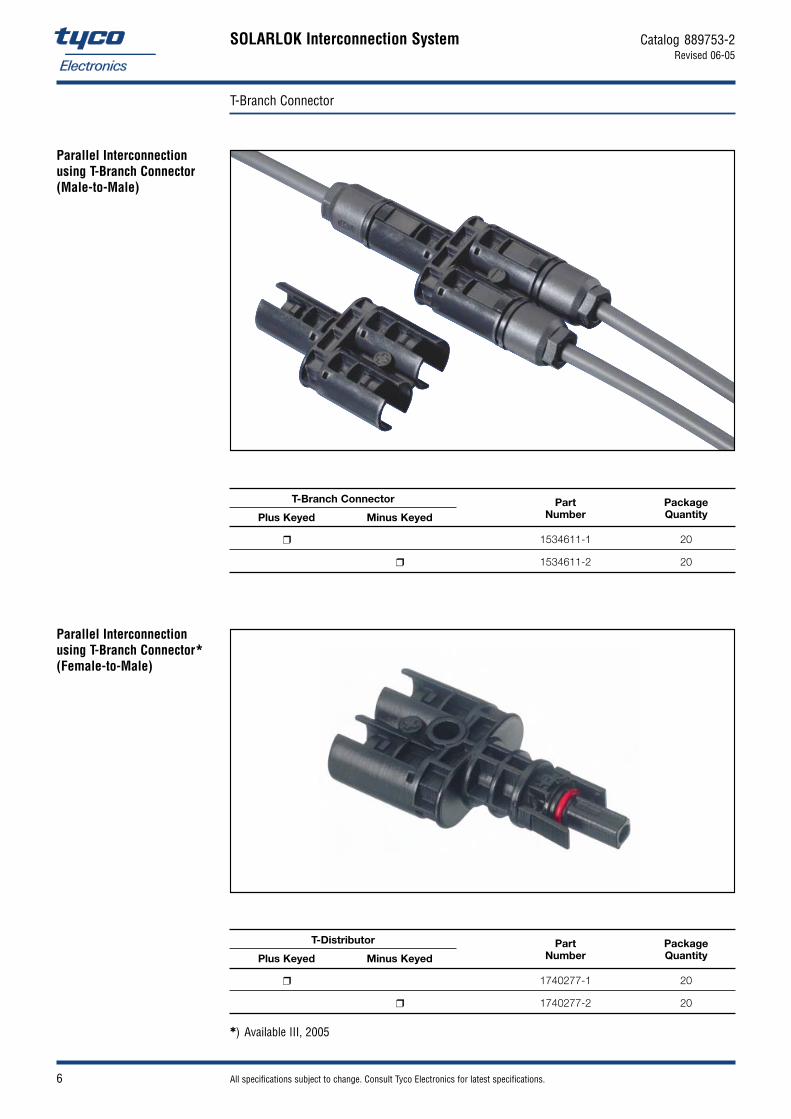
All specifications subject to change. Consult Tyco Electronics for latest specifications. 6
T-Branch Connector
SOLARLOK Interconnection System Catalog 889753-2Revised 06-05
1534611-1 20
1534611-2 20
Part Number
Package Quantity
T-Branch Connector
Plus Keyed Minus Keyed
Parallel Interconnection using T-Branch Connector (Male-to-Male)
Parallel Interconnection using T-Branch Connector*(Female-to-Male)
1740277-1 20
1740277-2 20
) Available III, 2005
Part Number
Package Quantity
T-Distributor
Plus Keyed Minus Keyed

All specifications subject to change. Consult Tyco Electronics for latest specifications. 7
DC/AC Converter Receptacle
SOLARLOK Interconnection System Catalog 889753-2Revised 06-05
Flat Seal and Plastic Nut With CoverO-Ring and Metal Nut
Part Number
Package Quantity Remarks
0-1394738-1 100
0-1394738-2 100O-Ring and Metal Nut
0-1394738-3 100
0-1394738-4 100
0-1740210-1 100
0-1740210-2 100Flat Seal and Plastic Nut
0-1740210-3 100
0-1740210-4 100
0-1394739-1 100 Cover
Wire Size
2.5 mm2 4.0 mm2
(AWG 14) (AWG 12)
Keying
Plus Minus

All specifications subject to change. Consult Tyco Electronics for latest specifications. 8
Solar Cable
SOLARLOK Interconnection System Catalog 889753-2Revised 06-05
Material and Finish
Conductor: Stranded tin plated copper
Insulation: Electron beam cross-linkedPolyolefin
Sheath: Electron beam cross-linked halogen free Polyolefin
Color: Black, blue, red
Standards: IEC 60228 classe 5 (Stranded tin plated copper and flexible); TÜV certified
As part of expanding theSOLARLOK Product Line,Tyco Electronics has specifieda wire that is designed to meetthe harsh environmental conditions typical in the wiringof photovoltaic installations.
The flexible, dual wall, halogenfree and cross linked solarwire offers long term stabilityand TÜV approval.
Its outstanding features in-clude: high resistance against environmental conditions likehumidity, UV-radiation andozone.
In addition, it has excellentresistance to abrasion andtemperature extremes.
The wire has a high dielectricwithstand voltage and with its fine-stranded, tin plated copper conductor, it is easy to handle and to strip.
Electrical Features
Voltage Rating U0 /U: 1,800/3,000 V AC / 2,600 V DC
Test Voltage for 5 Minutes: 6000 V
Max. Current Carrying Capacity (Free in Air): 36 A up to 116 A (size dependant)
Mechanical Features
Max. Conductor Temperature Continuous: +110 °C At Short Circuit: +250 °C
Min. Operating Temperature Free Installation: –25 °C Fixed Installation: –40 °C
Wire Size Range: 2.5 mm2 (AWG 14), 4.0 mm2 (AWG 12), 6.0 mm2 (AWG 10)
Min. Bending Radius: 5 x cable wire diameter, fixed installation
Product Facts
Dual wall insulation
Electron beam cross-linked
Excellent resistance to UV, water, ozone, fluids, salt, general weathering
Excellent resistance to abrasion
Halogen free, flame retardant,low toxicity
Very low smoke emissions
Excellent flexibility and stripping performance
Wire size from 2.5 mm2
up to 6.0 mm2
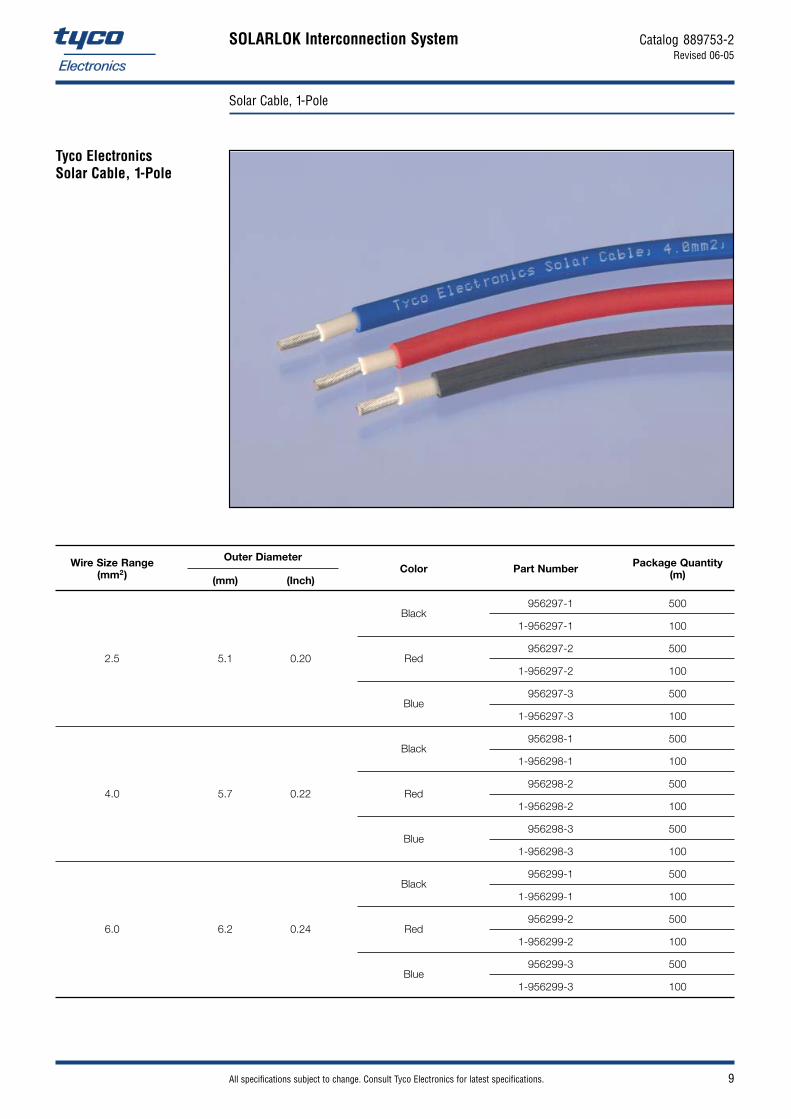
All specifications subject to change. Consult Tyco Electronics for latest specifications. 9
Solar Cable, 1-Pole
SOLARLOK Interconnection System Catalog 889753-2Revised 06-05
Package Quantity(m)Part NumberWire Size Range
(mm2) ColorOuter Diameter
(mm) (Inch)
Black0-956297-1 500
1-956297-1 100
2.5 5.1 0.20 Red0-956297-2 500
1-956297-2 100
Blue0-956297-3 500
1-956297-3 100
Black0-956298-1 500
1-956298-1 100
4.0 5.7 0.22 Red0-956298-2 500
1-956298-2 100
Blue0-956298-3 500
1-956298-3 100
Black0-956299-1 500
1-956299-1 100
6.0 6.2 0.24 Red0-956299-2 500
1-956299-2 100
Blue0-956299-3 500
1-956299-3 100
Tyco Electronics Solar Cable, 1-Pole

All specifications subject to change. Consult Tyco Electronics for latest specifications. 10
Interconnection Examples
SOLARLOK Interconnection System Catalog 889753-2Revised 06-05
1394462-4 6-1394461-2
1394462-3
1394462-3
1394738-3
1394461-4
1394462-4
1394738-4
Serial Interconnection for Junction Boxes with Cable Glands (4.0 mm2 Wiring)
DC/AC Converter
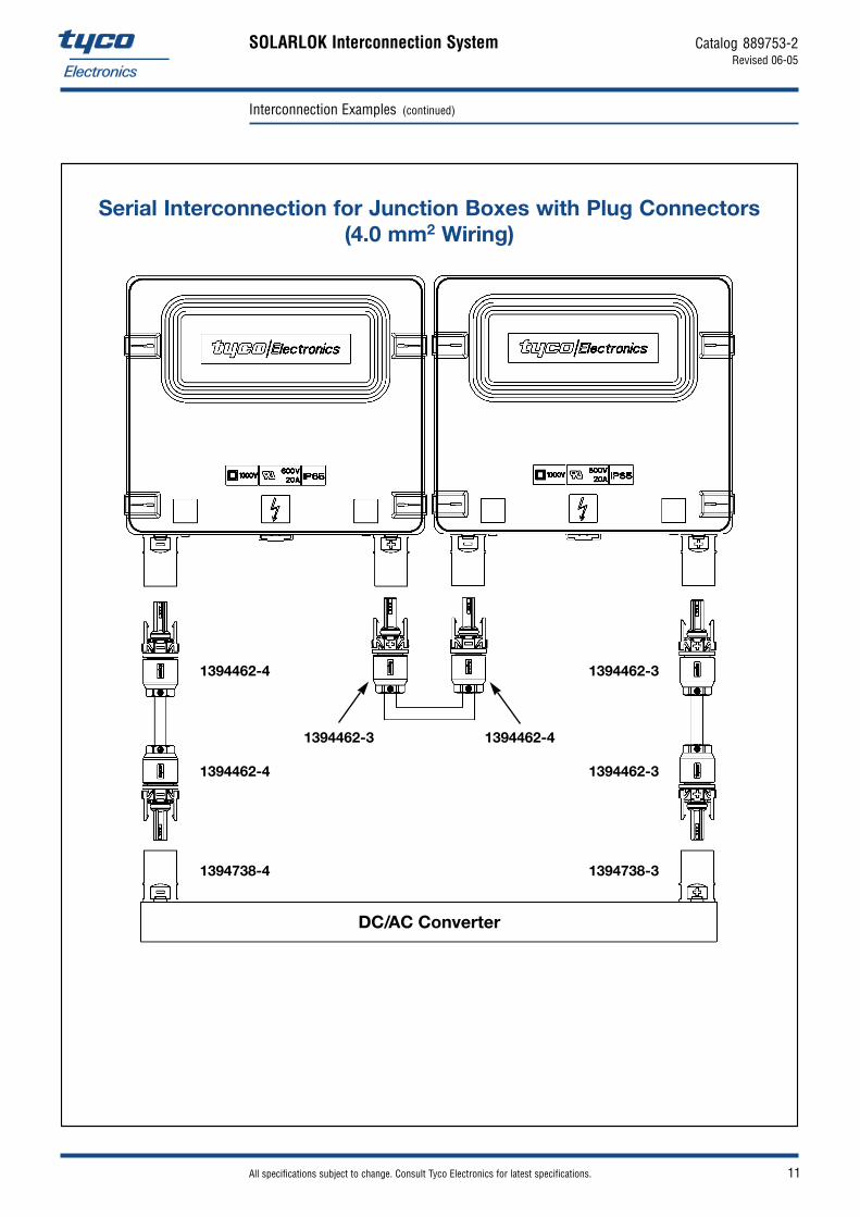
All specifications subject to change. Consult Tyco Electronics for latest specifications. 11
Interconnection Examples (continued)
SOLARLOK Interconnection System Catalog 889753-2Revised 06-05
1394462-4
1394462-3 1394462-4
1394462-4
1394738-4
1394462-3
1394462-3
1394738-3
Serial Interconnection for Junction Boxes with Plug Connectors (4.0 mm2 Wiring)
DC/AC Converter

All specifications subject to change. Consult Tyco Electronics for latest specifications. 12
Application Tooling
SOLARLOK Interconnection System Catalog 889753-2Revised 06-05
Hand Crimping Tool incl. Vario Crimp Head and Locator Part Numbers 1-1579004-1 (1.5 + 2.5 mm2) 1-1579004-2 (4.0 + 6.0 mm2)
Vario Crimp Head 7-1579001-8 (1.5 + 2.5 mm2) 7-1579001-9 (4.0 + 6.0 mm2)
Hand Crimping Tool incl. Vario Crimp Head and Locator Part No. 1579004-8 (for 1.5 + 2.5 + 4.0 + 6.0 mm2)
Die Set Part No. 6-1579001-6 (for 1.5 + 2.5 + 4.0 + 6.0 mm2)
Insulation Stripper includes length stop for all wiresizes: 1.5 mm2, 2.5 mm2, 4.0 mm2
and 6.0 mm2.
Suitable for Tyco ElectronicsSolar Cable.
Part No. 1-1579002-2
Extraction Tool suitable for all wire sizes
Part No. 1102855-3
Adapter for Vario Crimp Head: Part No. 1579000-4
Vario Crimp Head (1.5 and 2.5 mm2): Part No. 7-1579001-8
Vario Crimp Head (4.0 and 6.0 mm2): Part No. 7-1579001-9
Vario Crimp Head (AWG 10): Part No. 8-1579001-2
Vario Crimp Head (AWG 12): Part No. 5-1579001-5
Vario Crimpkopf (AWG 14): Part No. 5-1579001-4
Cable Assembly Tooling
SOLARLOK Electric Terminator CS 200
Base Machine: Part No. 539630-1

All specifications subject to change. Consult Tyco Electronics for latest specifications. 13
Application Tooling (continued)
SOLARLOK Interconnection System Catalog 889753-2Revised 06-05
Junction Box Assembly Tooling
Field Service Kit
Part No. 1534858-1 (Metric Wire)
Wire Spring Clamp Tool
Part No. 1579007-2
Dioden / Jumper Spring Clamp Tool
Part No. 1579007-5
Foil Spring Clamp Tool
Part No. 1579007-3
Kit includes the following parts:
100 Cable Coupler (Housings, Plus and Minus coded)
Crimp Contacts (4.0 and 6.0 mm2)
Strain Relief
Seals
Hand Crimp Tool: Part No. 1-1579004-2
Extraction Tool: Part No. 1102855-3
Insulation Stripper: Part No. 1-1579002-2

All specifications subject to change. Consult Tyco Electronics for latest specifications. 14
Assembly and Installation Guidelines
SOLARLOK Interconnection System Catalog 889753-2Revised 06-05
Table of Contents Page
SOLARLOK Plug Connectors . . . . . . . . . . . . . . . . . . . . . . . . . . . . . . . . . . . . . . . . . . . . . . . . . . . . . . . 14
1. General Comments . . . . . . . . . . . . . . . . . . . . . . . . . . . . . . . . . . . . . . . . . . . . . . . . . . . . . . . . . . . 14
2. Termination of the Cable Wires / Crimping of the Contacts . . . . . . . . . . . . . . . . . . . . . . . . . . . . . . 14
3. Handling of the Connectors . . . . . . . . . . . . . . . . . . . . . . . . . . . . . . . . . . . . . . . . . . . . . . . . . . . . . 14
3.1 Selection of Sealing Grommet for Cable Connectors . . . . . . . . . . . . . . . . . . . . . . . . . . . . . . . . . . . 14
3.2 Connector Latching . . . . . . . . . . . . . . . . . . . . . . . . . . . . . . . . . . . . . . . . . . . . . . . . . . . . . . . . . . . 16
3.3 Disconnecting . . . . . . . . . . . . . . . . . . . . . . . . . . . . . . . . . . . . . . . . . . . . . . . . . . . . . . . . . . . . . . . 16
3.4 DC/AC Converter Receptacle . . . . . . . . . . . . . . . . . . . . . . . . . . . . . . . . . . . . . . . . . . . . . . . . . . . . 17
4. Application Examples . . . . . . . . . . . . . . . . . . . . . . . . . . . . . . . . . . . . . . . . . . . . . . . . . . . . . . . . . 18
5. Storage . . . . . . . . . . . . . . . . . . . . . . . . . . . . . . . . . . . . . . . . . . . . . . . . . . . . . . . . . . . . . . . . . . . 18
6. Tooling . . . . . . . . . . . . . . . . . . . . . . . . . . . . . . . . . . . . . . . . . . . . . . . . . . . . . . . . . . . . . . . . . . . . 18
Attention: This connector is to be used only to interconnect firmly fixed cables.
Do not disconnect under load. Current path should only be disconnected using approved disconnect devices.
Cable assemblies shall be labeled with Part No. 1394470-1.
1. General Comments Any kind of pollution (dust, humidity, etc.) during the assembly process can degrade contact and connector performance. This applies in particular to the seals and the crimping of the contacts.
A clean assembly environment is therefore essential.
2. Termination of the SOLARLOK connectors use different crimp contacts for various wire gauges. Cable Wires and Crimping Possible wire gauges are 1.5 mm2, 2.5 mm2, 4.0 mm2, 5.3 mm2 und 6.0 mm2 resp. of the Contacts AWG 16, AWG 14, AWG 12 and AWG 10.
The tools to be used are selected based upon the wire gauge. For the application specification, please refer to specification # 114-74013.
3.1 Handling of the Connectors
3.1 Selection of Use only appropriate wire gauges. 3.1 Sealing Grommet Besides the standard seal/pinch ring combination further five different seals are available.3.1 for Cable Connectors 4.0 mm grommet inner diameter (for insulation diameter from 3.2 to 4.3 mm), Part No. 1394465-5
5.0 mm grommet inner diameter (for insulation diameter from 4.3 to 5.3 mm), Part No. 1394465-1 6.0 mm grommet inner diameter (for insulation diameter from 5.3 to 6.2 mm), Part No. 1394465-2 7.0 mm grommet inner diameter (for insulation diameter from 6.2 to 7.2 mm), Part No. 1394465-3 8.0 mm grommet inner diameter (for insulation diameter from 7.2 to 8.0 mm), Part No. 1394465-4
The grommet has to be matched with the outer diameter of the solar cable (see customer drawing, Part No. 1394461 and Part No. 1394462) and the pinch ring (Part No. 1418677-2) must be applied.
SOLARLOK Plug Connector
To protect against shock, ensure that conductors and their associated connectors areseparated from opposite polarity components.

All specifications subject to change. Consult Tyco Electronics for latest specifications. 15
Assembly and Installation Guidelines (continued)
SOLARLOK Interconnection System Catalog 889753-2Revised 06-05
When assembling the connectors, the following sequence must be followed:
1 Stripping the Wire (please refer to application specification # 114-74013)
2 Insert the stripped wire into the wire crimp barrel until it stops. While holding the wire in place, squeeze tool handles together until ratchet releases.
3 Place seal/pinch ring combination into the connector housing until it stops.
4 Place backshell onto the connector housing.
5 Push contact with cable into the connector housing until you hear the contact is locked into position
6 Tighten backshell nut to 1.5 Nm
Fig. 4
Fig. 18,0 mm
Fig. 2
Fig. 3
Fig. 5
Fig. 6

All specifications subject to change. Consult Tyco Electronics for latest specifications. 16
Assembly and Installation Guidelines (continued)
SOLARLOK Interconnection System Catalog 889753-2Revised 06-05
Disconnect circuit from load before unplugging connectors.
Cable assemblies should be labeled using Tyco Label, Part No. 1394470-1.
Unmating of the connector CAUTION: Do not disconnect the connector under load!
1 The locking mechanism is opened by depressing the latches.
2 Pull out the connectors. While depressing the latches, disconnect the connector by pulling the connector halves apart.
When mating the SOLARLOK connectors, ensure the following:
Connectors labeled with a plus or minus are keyed and can only be mated to similarly marked andkeyed connectors.
The polarity of the “neutral” connector must labeled with Part No. 1394725-1 or Part No. 1394725-2nearby the connector.
The connector system is fully latched only when the latches are flush with the mating connector.
After the connector is fully latched, the optional latch locking clip may be snapped into place.
Fig. 7(Female Connector)
3.2 Connector Latching
3.3 Disconnecting
CAUTION: The “neutral” designated pin connectors incorporate no keying features and mustonly be used for Serial Interconnection of Photovoltaic Modules.The neutral product should not be used where maintaining polarity is critical.
CAUTION: This connector must not be disconnected under load.
Fig. 8
1
1
2
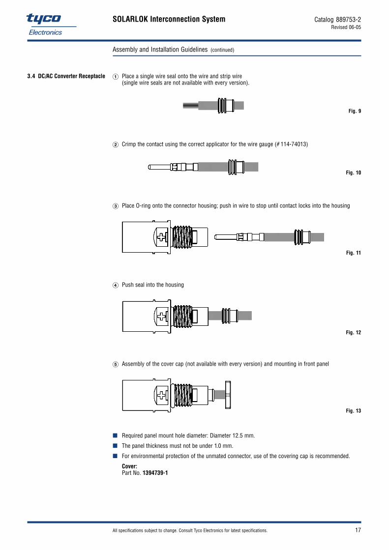
All specifications subject to change. Consult Tyco Electronics for latest specifications. 17
Assembly and Installation Guidelines (continued)
SOLARLOK Interconnection System Catalog 889753-2Revised 06-05
1 Place a single wire seal onto the wire and strip wire (single wire seals are not available with every version).
2 Crimp the contact using the correct applicator for the wire gauge (# 114-74013)
3 Place O-ring onto the connector housing; push in wire to stop until contact locks into the housing
4 Push seal into the housing
5 Assembly of the cover cap (not available with every version) and mounting in front panel
Required panel mount hole diameter: Diameter 12.5 mm.
The panel thickness must not be under 1.0 mm.
For environmental protection of the unmated connector, use of the covering cap is recommended.
Cover: Part No. 1394739-1
3.4 DC/AC Converter Receptacle
Fig. 9
Fig. 10
Fig. 11
Fig. 12
Fig. 13

All specifications subject to change. Consult Tyco Electronics for latest specifications. 18
Assembly and Installation Guidelines (continued)
SOLARLOK Interconnection System Catalog 889753-2Revised 06-05
5. Storage See Product Specification 108-18701
6. Tooling The following tools are available for the contact crimping (please specify wire gauge required):
Hand Tool, integral Locator and Die (Part No. 1-1105851-8), use ‘HVT’ position on locator
Hand Tool, only (Part No. 539973-1)
An extraction tool (Part No. 1102855-3) is needed to disassemble the connector components. This tool is used to unlock the contact retention features, after which the contact can be removed andre-used if necessary.
Technical Description
Fig. 16
Fig. 14: Serial (Wire Diagram) Fig. 15: Parallel (Wire Diagram)
4. Application Examples

All specifications subject to change. Consult Tyco Electronics for latest specifications. 19
Technical Data
SOLARLOK Interconnection System Catalog 889753-2Revised 06-05
Materials
Socket and Pin Contacts: CuZn
Housing: PPO, weatherproof against UV radiation and ozone
Color
Connector, Junction Box: Black
Electrical Features
Withstanding Voltage: 1000 V DC
Current Rating: 25 A
Contact Resistance: 5 m
Contact Resistance (typical): 1 m
Protection Class: II
Mechanical Features
Junction Boxes
Dimensions: 150 x 150 x 25 mm or 90 x 138 x 22 mm, respective ly
Temperature Range: –40 °C to +105 °C
Wire Size Range: up to AWG 12
Protection Degree: IP 65, closed
Connector
Dimensions: Diameter 18 mm, (diameter 0.71 inch)
Temperature Range: – 40 °C to +105 °C
Wire Size Range: AWG 14, AWG 12, AWG 10 stranded wire
Protection Degree: IP 67, mated
Contact Finish: silver plated,
Mating Cycles: 50, silver plated
Unmating Force: 30 –40 Newton
Additional Features: Coded housing ensures mating safety Contact voltage-proof Connector with crimp technology
Standards IEC 61215, 61646, Protection Class II, UL 1703
Subject to Change.

All specifications subject to change. Consult Tyco Electronics for latest specifications. 20
Numerical Index
SOLARLOK Interconnection System Catalog 889753-2Revised 06-05
Part Number Page
539630-1 12
539973-1 18
956297-1 9
956297-2 9
956297-3 9
1-956297-1 9
1-956297-2 9
1-956297-3 9
956298-1 9
956298-2 9
956298-3 9
1-956298-1 9
1-956298-2 9
1-956298-3 9
956299-1 5, 9
956299-2 9
956299-3 9
1-956299-1 9
1-956299-2 9
1-956299-3 9
1102855-3 12, 13, 18
1-1105851-8 18
1394461-1 5
1394461-2 5
1394461-3 5
1394461-4 5, 10
6-1394461-1 5
6-1394461-2 5, 10
6-1394461-4 5
6-1394461-5 5
6-1394461-6 5
Part Number Page
1394462-1 5
1394462-2 5
1394462-3 5, 10, 11
1394462-4 5, 10, 11
5-1394462-5 5
5-1394462-6 5
1394465-1 14
1394465-2 14
1394465-3 14
1394465-4 14
1394465-5 14
1394470-1 14, 16
1394723-3 2
1394723-4 2
1394723-5 4
1394723-6 4
1394723-9 4
1-1394723-6 2
1-1394723-8 2
2-1394723-1 2
2-1394723-5 2
2-1394723-7 2
1394725-1 16
1394725-2 16
1394738-1 7
1394738-2 7
1394738-3 7, 10, 11
1394738-4 7, 10, 11
1394739-1 7, 17
1418677-2 14
1418867-1 3
Part Number Page
1418867-2 3
1534226-1 5
1534611-1 6
1534611-2 6
1534858-1 13
1579000-4 12
5-1579001-4 12
5-1579001-5 12
6-1579001-6 12
7-1579001-8 12
7-1579001-9 12
8-1579001-2 12
1-1579002-2 12, 13
1579004-8 12
1-1579004-1 12
1-1579004-2 12, 13
1579007-2 13
1579007-3 13
1579007-5 13
1740077-1 2
1740210-1 7
1740210-2 7
1740210-3 7
1740210-4 7
1740220-1 3
1740220-2 3
1740220-3 3
1740220-4 3
1740277-1 6
1740277-2 6
1740425-1 3

HIGH RELIABILITY - EASY INSTALLATIONINTERCONNECT SOLUTIONS FOR WIND ENERGY
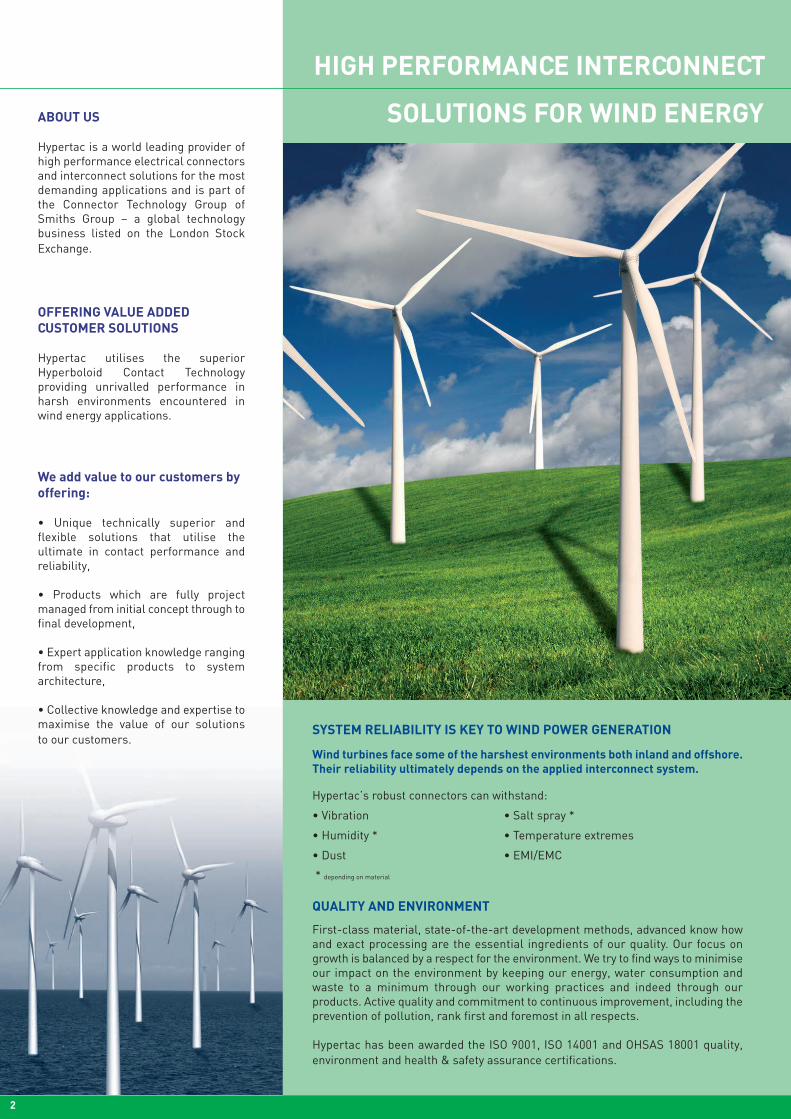
HIGH PERFORMANCE INTERCONNECT
SOLUTIONS FOR WIND ENERGYABOUT US
Hypertac is a world leading provider ofhigh performance electrical connectorsand interconnect solutions for the mostdemanding applications and is part ofthe Connector Technology Group ofSmiths Group – a global technologybusiness listed on the London StockExchange.
OFFERING VALUE ADDED CUSTOMER SOLUTIONS
Hypertac utilises the superiorHyperboloid Contact Technologyproviding unrivalled performance inharsh environments encountered inwind energy applications.
We add value to our customers byoffering:
• Unique technically superior andflexible solutions that utilise theultimate in contact performance andreliability,
• Products which are fully projectmanaged from initial concept through tofinal development,
• Expert application knowledge rangingfrom specific products to systemarchitecture,
• Collective knowledge and expertise tomaximise the value of our solutionsto our customers.
SYSTEM RELIABILITY IS KEY TO WIND POWER GENERATION
Wind turbines face some of the harshest environments both inland and offshore.Their reliability ultimately depends on the applied interconnect system.
Hypertac’s robust connectors can withstand:
• Vibration • Salt spray *
• Humidity * • Temperature extremes
• Dust • EMI/EMC
* depending on material
QUALITY AND ENVIRONMENT
First-class material, state-of-the-art development methods, advanced know howand exact processing are the essential ingredients of our quality. Our focus ongrowth is balanced by a respect for the environment. We try to find ways to minimiseour impact on the environment by keeping our energy, water consumption andwaste to a minimum through our working practices and indeed through ourproducts. Active quality and commitment to continuous improvement, including theprevention of pollution, rank first and foremost in all respects.
Hypertac has been awarded the ISO 9001, ISO 14001 and OHSAS 18001 quality,environment and health & safety assurance certifications.
2

SUPERIOR CONTACT TECHNOLOGY
UNRIVALLED SYSTEM PERFORMANCE
OUR INTERCONNECT SOLUTIONS FOR WIND TURBINES ARE BUILT UPON OUR UNIQUE HYPERBOLOID CONTACT TECHNOLOGY
THE HYPERTAC HYPERBOLOID CONTACT
The Hyperboloid socket has a number of spring wires, the position of which is defined by a wire carrier. This is fitted to an outer sleeveor shank that carries the termination of the socket.
The spring wires within the socket are set at a small angle to the centre line and are deflected when the mating pin contact enters.Each spring wire is deflected within its elastic limit and makes a line contact with the pin. A smooth wiping action reduces wear of theplating surfaces of the pin and socket wires. This construction allows a very tight control of the spring forces and hence the insertionand withdrawal forces.
The Hypertac Hyperboloid contact design ensures unrivalled performance in terms of:
• Multiple line contacts of low resistance maintainedunder high levels of shock and vibration,• During shock and vibration tests no discontinuitywhen measured down to 2 ns,• Low insertion forces,• Low wear of plating surfaces for long life,• Uniform electrical and mechanical characteristicsover a high number of mating operations,• High current rating,• No contact heating, therefore no degradation of theinsulator and no electrical and electronic equipmentsystem failure.
The Hypertac Hyperboloid contact provides the following commercial benefits:
• Low cost of ownership – no need to replace duringequipment life,• Reduced system costs – equipment design is lesscritical,• Reduced qualification costs – no re-testing due tocontact failures.
3
Wire Sleeve Before Insertion of Pin
Pin Partially Inserted into Sleeve
Pin Completely Inserted into Sleeve

COST EFFECTIVE
INTERCONNECT SOLUTIONS
4
Wind turbines are difficult to assess sothey require long life cycle connectorsystems. Hypertac’s self-cleaning andvibration proof interconnect solutionsare designed to “fit and forget” so thatmaintenance work can be reduced to aminimum throughout the long life spanof a wind turbine.
The complex structure of a wind turbinerequires an expansive area of cablesolutions for various functional areas:e.g. control systems, sensors for windspeed and wind direction, humidity,temperature and vibrations.
Heavy Duty modular connectors for signal, power, fibre optics, coax and high speed contacts
REP Series environmentally sealedquick interconnect solution
Modular L Series for rack and panel applicationsH Series high density mini modular cable/rack and panel connectors
C55 Series compact lightweight 55waymicro circular connector

RELIABILITY IS PARAMOUNT
5
HIGH POWERGauging stations on the nacelle are the control centre of the wind turbine. These stations have to withstand extreme weatherconditions including high wind speed, humidity, salt spray, dust and temperature extremes on a daily basis. A contact interruptioncould lead to a breakdown and become hazardous for the wind turbine. For this reason the use of high reliability, high power and longlife interconnect solutions is essential.
Hypertacs background in producing connectors for the harshest environments gives us the unique experience needed to producecost effective, high power connectors for wind energy engineering to be used in generator, inverter, transformer and slip ringapplications.
L-Series 300 amp modules
HBB Series 2/3 pole, 300 amp
HBC Series versions300 amp and 500 amp
Example of a wind turbine without gearboxPower: 5,0 megawattRotor diameter: 114 metresTower height: around 124 metresNumber of rotation: 8 to 13 revolutions per minute

As the wind power industry has developed,so has product standardisation. Hypertac’sindustrial connector series providesinterconnect solutions for wind energyapplications and environments, includinginternal power supplies, rack and panelconnections and motor control units.
M23 Stainless Steel Seriessignal and power
M23 multibus for all fieldbus systems
Circular Connectors M23, M40, M58signal and power
M12 Series up to 6 amp
GS Series D-Sub rectangular I/O
6
INDUSTRIAL STANDARD CONNECTORS
Hypertac offers the benefits of a large global business while maintaining itsgeographic presence. The customer is supported by design and manufacturing sitesin America, Europe, Africa and Asia and by a global network of agents anddistributors. This structure ensures that customers are able to interact withengineers and sales colleagues who speak their own language, have acomprehensive knowledge of the range of products available throughout the groupand can draw on experience from working in particular application environments.
Motion Control Cables 100% tested pre-fabricated wiring systems

7
RF & HIGH SPEED
FILTER & TRANSIENT SUPPRESSION
OUR EMI FILTER KNOWLEDGE ENABLES US TO:
• Specify/recommend optimum filter style (e.g. C, LC, Pi) and value (up to 1microFarad) on receipt of signal type and data rate,• Provide insertion loss simulations/prediction that account for actual source and load impedances,• Verify insertion loss performance across entire frequency range,• Combine EMI Filter and Transient Protection within a single connector,• Provide Transient Protection in accordance with RTCA D 160F waveform and level specifications. Higher customers expectationsand severe application requirements have helped drive new levels of integrated product solutions between Hypertac and the sisterorganisation PolyphaserITranstector,• Adopt the most appropriate filtering technology for the application.
Optical fibre cables are the favoured choice for communicating from the wind turbine to the wind farm central monitoring controlsdue to high bandwidth, long transmission distances and noise immunity. Fibre optic connectors are also available in sealedinterfaces.
Fibre optic connectors and contacts
Micro twinax and quadrax connectors
Coax, triax and quadraxconnectors and contacts
RF Lightning Protection / 24 VDC Surge Supression
OUR RF & HIGH SPEED KNOWLEDGE ENABLES US TO:
• Design and manufacture contacts operating at frequencies upto 40 GHz and above 4Gbps,• Optimise contact design for specific cable characteristics,• Provide insertion loss, VWR and Eye Pattern and S Parametersimulations,• Verify high frequency and data transmission performanceacross entire frequency range.
Modular connectors are becoming more common within thetower of the wind turbine. These connectors allow a flexible mixof cable styles for signal, power and optical terminations.
Within a single connector it is possible to have:• Coax, Triax, Quadrax contacts alongside signal and powercontacts,• Transient protection and EMI filtering,• All cable shields grounded directly to connector shell.

A
2010
Y-Sol® Photovoltaic
Cable Assemblies
Connectors and
Junction Boxes

Hermetic Sealed - One Step Process
Why Hermetic Sealed?
Customer advantages with our cable assembliesThe Hermetic Sealed technology combines the advantages of cost and quality - Less installation time required because of overmolded cable assemblies which are pre-assembled and
„ready-to-plug“.
- Permanent and safe operation of the PV plant. Y-Sol connectors fulfil the IP68 protection class. The overmolding process protects the inner parts and contacts. - Safe power transmission of up to 30A. - Standard products are available as well as customised solutions. - Long life time of the complete assembly even under harsh environmental conditions.
- Cross linked cables are used as standard.
What is the meaning of Hermetic Sealed?Hermetic Sealed is a one step overmolding process. In a one step process the connector is molded into its final shape and makes a solid connection with the cable. No screws or extra parts are needed. The overmolding forms a permanent hermetic sealing around the cable and contact (fig 1).
Yamaichi has developed this technology for the connectors Y-Sol3, Y-Sol3 T-Junction, Y-Sol4 and for the Thin Film Junction Box. These products come ready-to-plug to the customer. 100% tested for easy and safe assembly. For worldwide usage, the products are tested and certified by TÜV and UL.
fig 1. shows a 3D Hermetic Sealed Y-Sol3 T-Junction
One Step Process

Why Hermetic Sealed?
Customer advantages with our Thin Film Junction Box The TF J-Box from Yamaichi is delivered with cables and overmolded connectors. In addition to the advantages of our cable assemblies, the Hermetic Sealed TF J-Box has the following features: - Delivered as a pre-assembled Hermetic Sealed system, complete with cables and connectors.
- Configuration according to customer requirements.
- Fully overmolded integrated bypass diode. This guarantees safe operation under different lighting conditions or shadowing.
- The Hermetic Sealed diode is homogenously surrounded by plastic material. Heat generated by the diode is absorbed. This means reduced stress on the diode and longer life time (fig 2).
fig 2. The bypass diode is overmolded by plastic material. During shadowing the diode will heat up.This heat is absorbed and eliminated. The plastic material has a 30 times higher heatconductivity than air.
Diode fully overmolded

Y-Sol3 Cable Assemblies
Y-Sol3Ø 3mm contacts without locking
Certified: acc. to EN50521 (TÜV) acc. to UL 1703
Y-SOL3AOV - F1 - 4U - 1000 - GM*
Series No. for Overmolded (Hermetic Sealed) M1 = Male (with Partial Strip off) F1 = Female (with Partial Strip off) M2 = Male (with Blank Cut)F2 = Female (with Blank Cut) Cable Cross Section 2T = 2.5mm², with TÜV 4U = 4.0mm², with TÜV and UL 4T = 4.0mm², with TÜV 6T = 6.0mm², with TÜV Overall Length in mm (e.g. 1000 = 1 meter) GM* = Internal Style No. (determined by Yamaichi)
Part Number (example) and various combinations
Specifications
Description Y-SOL3
Diameter ∅13.5mm
Degree of protection IP68 (plugged) and IP20 (unplugged)
Protection class II
Cable cross section 2.5mm², 4.0mm² and 6.0mm²
Ambient temperature -40°C to +85C
Contact resistance < 5mΩ (typ. value 1mΩ up to 3mΩ)
Voltage rating 1,000 V DC acc. to TÜV EN50521 600 V DC acc. to UL 1703
Current rating 30A (based on 4mm² cross section)
Extraction force > 89 Newton
Cable pull-out force > 350 Newton
Y-Sol3 connector is a ready-made solar cable assembly,
“ready-to-plug“ in your PV installation.
100% controlled quality by Yamaichi.
Ready-to-Plug
For final part numbers please contact Yamaichi before odering

Specifications
Y-Sol3 T-Junction AssembliesY-Sol3 T-Junction is a ready-made solar cable assembly,
“ready-to-plug“ in your PV installation. It is made according
to customer requirements. The number of T-Junctions and
adapter cables can be freely specified.
100% controlled quality by Yamaichi.
Y-Sol3 T-JunctionØ 3mm overmolded cable harness for connection of PV panels in parallel configuration.
Certified: acc. to EN50521 (TÜV) acc. to UL 1703
Y-SOL3T - F 4 3 - 6T - 3200 - GM*
Series No. for Overmolded (Hermetic Sealed) M = Male F = Female Number of T-Junctions (e.g. 4)
Number of Adapter Cables (e.g. 3) Cable Cross Section 6T = 6.0mm², with TÜV 6U = 6.0mm², with TÜV and UL Overall Length in mm (e.g. 3200 = 3.2 meter) GM* = Internal Style No. (determined by Yamaichi)
Part Number (example) and various combinations
Description Y-SOL3 T-Junction
Diameter ∅17mm
Degree of protection IP68 (plugged) and IP20 (unplugged)
Protection class II
Cable cross section 6.0mm²
Ambient temperature -40°C to +85C
Contact resistance < 5mΩ (typ. value 1mΩ up to 3mΩ)
Voltage rating 1,000 V DC acc. to TÜV EN50521 600 V DC acc. to UL 1703
Current rating 30A (based on 6mm²)
Extraction force > 89 Newton
Cable pull-out force > 350 Newton
For final part numbers please contact Yamaichi before odering

Ready-to-Plug
Y-Sol4 Cable Assemblies
Part Number Y-SOL4-RELEASE-TOOL-SR
Y-SOL4 release tool
Description Y-SOL4
Height 12mm
Degree of protection IP68 (plugged) and IP20 (unplugged)
Protection class II
Cable cross section 1.5mm², 2.5mm² and 4.0mm²
Ambient temperature -40°C to +85°C
Contact resistance < 5mΩ (typ. value 1mΩ up to 3mΩ)
Voltage rating 1,000 V DC acc. to TÜV EN50521 600 V DC acc. to UL 1703
Current rating 30A (based on 4mm² cross section)
Extraction force > 89 Newton
Cable pull-out force > 350 Newton
Y-Sol4 is a ready-made solar cable assembly, “ready-to-plug“
in your PV installation. The Y-Sol4 connector has a security locking
function. Once closed a release tool is necesary to re-open the
connection. 100% controlled quality by Yamaichi.
Certified: acc. to EN50521 (TÜV) acc. to UL 1703
Specifications
Y-SOL4AOV - M1 - 4T - 1000 - GM*
Series No. for Overmolded (Hermetic Sealed) M1 = Male (with Partial Strip off) F1 = Female (with Partial Strip off) M2 = Male (with Blank Cut)F2 = Female (with Blank Cut) Cable Cross Section 1U = 1.5mm², with TÜV and UL2U = 2.5mm², with TÜV and UL4T = 4.0mm², with TÜV Overall Length in mm (e.g. 1000 = 1 meter) GM* = Internal Style No. (determined by Yamaichi)
Part Number (example) and various combinationsY-Sol4Ø 4mm contacts with locking
For final part numbers please contact Yamaichi before odering

Y-Sol4 Crimp Assembly Connector (C.A.T.)
The Y-Sol4 C.A.T. (Crimp Assembly Type) is a connector for field installation
by crimp connection. The connector comes in male and female types and has only
two parts to connect with the cable. The cable is assembled by using a standard
crimp tool. This crimping can be done manually or automatically.
Y-Sol4 C.A.T.Ø 4mm contacts - crimp type assembly
Customer Advantages 4 For manual or automatic assembly 4 Two piece design
4 Installation with a standard crimp tool
Y-Sol4 C.A.T. Male Connector
For Specifications please refer to table on next page
Y-Sol4 C.A.T. Female Connector
in preparation in preparation
Part 1
Part 2
Part 1
Assembled
Part 2
PVP0402 - 102 - 02 02 - 00*
Part Number (example) and various combinations
Series No. for Crimp Assembly Type PVP0402 = Plug PVS0402 = Socket Crimp Type Unit Packaging Cable Cross Section 01 = 1.5mm² to 2.5mm² 02 = 4.0mm² to 6.0mm² Cable Outer Dimension 02 = 5.8mm up to 7.0mm (other diameters are being planned) 00* = Internal Style No. (determined by Yamaichi)
For final part numbers please contact Yamaichi before odering
Crimp Type
Assembled

Y-Sol4 Free Assembly Connector (F.A.T.)
Tool Free
The Y-Sol4 F.A.T. (Free Assembly Type) is a connector for fast and safe field
installation. The connector comes in male and female types and has only two
parts to connect with the cable. The assembly is closed by simply screwing
the two parts together. There are absolutely no tools for this operation required.
Y-Sol4 F.A.T.Ø 4mm contacts - spring type assembly
Customer Advantages 4 No tool required 4 Two piece design
4 Installation in just three steps
PVP0402 - 202 - 02 02 - 00*
Part Number (example) and various combinations
Y-Sol4 F.A.T. Male Connector Y-Sol4 F.A.T. Female Connector
in preparation in preparation
Part 1
AssembledPart 2
Series No. for Free Assembly Type PVP0402 = Plug PVS0402 = Socket Spring Type Unit Packaging Cable Cross Section 01 = 1.5mm² to 2.5mm² 02 = 4.0mm² to 6.0mm² Cable Outer Dimension 02 = 5.8mm up to 7.0mm (other diameters are being planned) 00* = Internal Style No. (determined by Yamaichi)
Part 1
Assembled
Part 2
For final part numbers please contact Yamaichi before odering

Description Y-SOL4 F.A.T. / Y-SOL4 C.A.T.
Diameter ∅ 18.8mm
Degree of protection IP67
Protection class II
Cable cross section 1.5mm² to 2.5mm² and 4.0mm² to 6.0mm²
Cable outer diameter 5.8mm to 7.0mm (other dimensions are planned)
Ambient temperature -40°C to +85°C
Contact resistance < 5mΩ (typ. value 1mΩ up to 3mΩ)
Voltage rating 1,000 V DC acc. to TÜV EN50521 600 V DC acc. to UL 1703
Current rating 30A (based on 4mm² cross section)
Extraction force > 89 Newton
Step 3Tighten screw cap
Step 2Insert contact to housingin the direction of the arrow
Step 1Insert cable to contact. Close spring to hold cable
Assembly Process Spring Contact
Part Number (example) and various combinations
Specifications
NEW
spring

TF J-Box for Thin Film ModulesThe Y-Sol® Thin Film J-Box can be easily assembled either manually
or in an automatic assembly process. Contacting to the PV module
is realised by spring loaded contacts in the J-Box lid. One bypass
diode can be integrated optionally as per customer requirements.
100% controlled quality by Yamaichi.
Certified: acc. to EN50521 (TÜV) acc. to UL 1703
Y-SOL4B TFL 1 2 1U M06 F08 GM*
Series No. for Overmolded (Hermetic Sealed) TFS = Short TypeTFL = Long Type 0 = No Bypass Diode 1 = With Bypass Diode Two Spring Contacts
Cable Cross Section 1U = 1.5mm², with TÜV and UL 2U = 2.5mm², with TÜV and UL M06 = Male Cable (e.g. 06 = 0.6 meter) F08 = Female Cable (e.g. 08 = 0.8 meter) GM* = Internal Style No. (determined by Yamaichi)
Part Number (example) and various combinationsTF J-Box
Description TF J-Box
Dimensions (L x W x H) in mm Short Type: 60 x 70 x 12 Long Type: 68 x 70 x 12
Degree of protection IP65
Protection class II
Number of diodes Optional with one bypass diode
Number of ribbons 2
Ribbon width max. 10mm
Conductor cross section 1.5mm² and 2.5mm²
Voltage rating 1,000 V DC acc. to TÜV EN50521 600 V DC acc. to UL 1703
Current rating up to 7A depending on J-Box configuration
Specifications
Special Features Spring loaded contacts Double sided adhesive Customer Advantages No tools required Easy and safe contact assembly Simple mounting to module
For final part numbers please contact Yamaichi before odering
Junction Boxes

Part Number (example) and various combinations
Series No. Y-SOL3B with Y-Sol3 Y-SOL4B with Y-Sol4 Si Wafer J-Box Number of Bypass Diodes(3 is standard) Number of Contacts/Rails C = Clamped Contacts S = Solder Contacts 1 = PCB Standard Type2 = Non Ribbon Crossing Type Cable Cross Section 4T = 4.0mm², with TÜV 6T = 6.0mm², with TÜV M10 = Male Cable overall Length (e.g. 10 = 1 meter) F8 = Female Cable overall Length (e.g. 8 = 0.8 meter) GM* = Internal Style No. (determined by Yamaichi)
For final part numbers please contact Yamaichi before odering
Y-SOL4B SI 3 4 C 1 4T M10 F8 GM*
Universal J-Box for Silicon Wafer ModulesFeaturing SMD diode technology, the Y-Sol® Universal J-Box shows approx. 40% less
heat development compared to J-Boxes with conventional radial diodes. Automated
assembly in an assembly line is possible, either by spring or soldering connection.
It is one of the flatest Silicon Wafer J-Boxes on the market (<27mm height) and features
integrated cable holders. 100% controlled quality by Yamaichi.
Description Universal J-Box
Dimensions (LxWxH) 111 x 140 x 26.5
Degree of protection IP67
Protection class II
Number of diodes Optional with up to 6 bypass diodes
Number of ribbons 2 - 8
Ribbon width max. 7.5mm
Conductor cross section 4.0mm² and 6.0mm²
Voltage rating 1,000 V DC acc. to TÜV EN50521
Current rating up to 20A depending on J-Box configuration
SMD Diode
In case of a short-cut there is 40% less heat in the PV junction box This means more saftey in operation
Special Feature
Customer Advantages
Universal J-Box
Specifications
Certified: acc. to EN50521 (TÜV)
Y-SOL4B TFL 1 2 1U M06 F08 GM*

Reduced to the Optimum Yamaichi Eco-Si J-Box for Silicon Wafer Modules
4 Mechanical Rating: IP67
4 Number of Diodes: up to 3 bypass diodes
4 Number of Ribbons: up to 4
4 Voltage Rating: 1,000V DC
4 Current Rating: 12A
4 For welding or soldering connection
4 Ready equipped with Y-Sol3 or Y-Sol4 connector
The cost effective solution for Silicon Wafer Modules with up to 3 bypass diodes
The Eco-Si Junction Box
Silicon is a Semiconductor. It is conductive under light. It becomes non conductive when shadowed. In the case of partial shadowing on a PV panel, the affected cell area must be controlled by the Junction Box
The Intelligent Junction Box
New Innovative Products Coming Soon
Aug 2010
4 Intelligent System Power Control on module level
4 Wireless Communication
4 Power Organisation by a transistor controlled J-Box with Maximum Power Point (MPP) tracking on module level
4 Monitoring and Control
YAMAICHI ELECTRONICSDeutschland GmbHKarl-Schmid-Str. 981829 Munich Germany
Tel.: +49 (0) 89 45 10 9 - 0Fax: +49 (0) 89 45 10 9 - 110 e-mail: [email protected]: www.yamaichi.eu
YAMAICHI ELECTRONICS Italia s.r.I.Centro Direzionale ColleoniVia Colleoni, 1 - Pal. Taurus Ing. 120041 Agrate Brianza (MI) Italy
Tel.: +39 039 6881185Fax: +39 039 689 2150e-mail: [email protected]: www.yamaichi.eu
YAMAICHI ELECTRONICS GB Ltd.Unit 4, Woodlands Business Village, Coronation Road, BasingstokeHampshire RG21 4JXEngland
Tel.: +44 (0)1256 463131Fax: +44 (0)1256 463132e-mail: [email protected]: www.yamaichi.eu
For further information please contact Yamaichi
PV panel performance data send to
Active Combiner
Monitoring and Control using a PC environment for isolating problems
Intelligent J-Box
WirelessActive Combiner
sends on data to PC

11 V 115
Certified QualityManagement System
Connettori serie CS4
CS420SERIE PANNELLO
CS411 - CS412SERIE VOLANTE
Certificato n. R60040256
sistemi di connessione per fotovoltaico
La Gamma
Caratteristiche tecnicheTensione di esercizio: 1000 VDCTensione impulsiva 8 kVTensione di isolamento 4 kVCorrente di esercizio 30 ANorma di riferimento EN 50521:2008Classe di applicazione Class AClasse di protezione Class IIGrado di inquinamento 3Categoria di sovratensione IIITemperatura ambiente min. -40 °CTemperatura ambiente Max. +85 °CTemperatura limite 105 °CTipo di conduttore flessibileTipologia terminali a comprimere
Intervallo diametro serracavoø min. 4,4 ± 0,2 mmø Max. 7,2 ± 0,2 mm
Numero poli 1Sezione conduttori 2,5 – 4,0 e 6,0 mm2Grado di protezione IP 67Terminale riutilizzabile noCoppia di serraggio ghiera pressacavo 1,5 Nm
CS4 GRCS4 FC
CS4 MC
CS4 KEY
Tipo Descrizione Sezionemm2
Ø esterno cavo mm
Imballostandard / minimo
CS411 Coppia connettori CS4 esecuzione volante 2,5 - 4 - 6 4,4 ÷ 5,8 100/10
CS412 Coppia connettori CS4 esecuzione volante 2,5 - 4 - 6 5,8 ÷ 7,2 100/10
CS420 Coppia connettori CS4 esecuzione da pannello 2,5 - 4 - 6 4,4 ÷ 7,2 100/10
Tipo Descrizione Imballostandard / minimo
CS4 KEY Chiave multifunzione per connettori CS4 100/10
CS4 MC Cappuccio in gomma per connettore CS4.. maschio 1.000/100
CS4 FC Cappuccio in gomma per connettore CS4.. femmina 1.000/100
CS4 GR Gommino per connettori CS4.. femmina/maschio 1.000/100

Connettore maschio volante
Connettori serie CS4sistemi di connessione per fotovoltaico
60,4
18,85
12,10
Tipo Sezionemm2
Ø esterno cavo mm
CS411M2,5 - 4 - 6
4,4 ÷ 5,8CS412M 5,8 ÷ 7,2
Parte Descrizione1 Ghiera serracavo (PPO)2 Gabbia antistrappo (Resina Acetalica)3 Gommino di tenuta (EPDM)4 Corpo connettore maschio (PPO)5 Terminale maschio (Lega Cu)
Connettore femmina volante1
23 4 5
6
50.4
Ø19.3
Connettore maschio da pannello
6
10,0551,5
18,85
M16x1,25
12,10
Tipo Sezionemm2
Ø esterno cavo mm
CS411F2,5 - 4 - 6
4,4 ÷ 5,8CS412F 5,8 ÷ 7,2
Parte Descrizione1 Ghiera serracavo (PPO)2 Gabbia antistrappo (Resina Acetalica)3 Gommino di tenuta (EPDM)4 Corpo connettore femmina (PPO)5 O-ring (EPDM)6 Terminale femmina (Lega Cu)
Tipo Sezionemm2
Ø esterno cavo mm
CS420M 2,5 - 4 - 6 4,4 ÷ 7,2
Parte Descrizione1 Dado di fissaggio (PPO)2 Guarnizione (NBR)3 Corpo connettore maschio (PPO)4 Terminale maschio (Lega Cu)
Connettore femmina da pannello1
2
43
5
40,9
Ø19,3
M16x1,25
6
Tipo Sezionemm2
Ø esterno cavo mm
CS420F 2,5 - 4 - 6 4,4 ÷ 7,2
Parte Descrizione1 Dado di fissaggio (PPO)2 Guarnizione (NBR)3 O-ring (EPDM)4 Corpo connettore femmina (PPO)5 Terminale femmina (Lega Cu)
Cembre S.p.A. Via Serenissima, 9 25135 Brescia (Italia)Telefono: 030 36921Telefax: 030 3365766 E-mail: [email protected]
Uffici Vendite RegionaliMilano Tel. 0392103208 - Fax. 0392148036 • E-mail:[email protected] Tel. 03036921 - Fax. 0302359433 • E-mail:[email protected] Tel. 049620093 - Fax. 049720488 • E-mail:[email protected] Tel. 051383474 - Fax. 051382846 • E-mail:[email protected] Tel. 055790711 - Fax. 055790711 • E-mail:[email protected]
Ufficio Vendite NazionaleSede Tel. 03036921 - Fax. 0302359431 • E-mail:[email protected]
www.cembre.com

MEDER electronic | www.meder.com | November, 2009 Page 1 of 2
High Voltage / High Current Reed Relays
REED RELAYS REED SENSORS REED SWITCHES
Reed Technology Solutions
Product Spotlight
MEDER electronic features a full line of reed relays
offering high voltage and high power configurations for
PCB mount or free-standing applications.
MEDER High Voltage Reed Relays are designed to
switch high voltages, stand off even higher voltages, and
carry very high current levels.
These series feature switching voltages up to 10,000
VDC and breakdown voltages to 15,000 VDC with
1,000 Gigaohms between coil and contact. The
relays can carry current up to 15 Amps continuous
and 30 Amps pulsed. Mounting include PCB mount
or axial high voltage leaded versions.
DESCRIPTION
A full spectrum of sizes, power,
and high voltage switching options
are just a few features offered,
among the seven types of MEDER
High Voltage/ High Current Reed
Relays. Switching voltages as
high as 10kVDC and breakdown
voltages to 15kVDC. Continuous
carry currents up to 15 Amps and
pulsed currents 30 Amps.
FEATURES
Single pole single throw
Normally open (1 Form A),
Normally closed (1 Form B)
Double pole single throw
Normally open (2 Form A)
Switching voltages 0-10kVDC
Breakdown voltages up to
15kVDC
High voltage termination wire
available
PCB mounting
Hermetically sealed switches
with epoxy encapsulation
Dynamically tested contacts
Millions of reliable operations
Carry currents up to 15 Amps
continuous (with higher pulsed
currents)
APPLICATIONS
H Series- Cable Test Equipment,
Defibrillators, Electrosurgical Generator
used with Electronic Scalpel for
Electrocauterization, Replacement of
Mercury Wetted Relays
HF Series- Radio Transmitters 1 MHz to 30
MHz, Communication Equipment, Antenna
Transmitter and Receive applications
HE / HM Series- Cable Test Equipment,
Defibrillators, Electrosurgical Generator
used with Electronic Scalpel for
Electrocauterization, Replacement of
Mercury Wetted Relays
MRE Series- Automated Test Equipment,
Portable Defibrillators, General Purpose
Electronic Test Equipment
LI Series- Automated Test Equipment,
Portable Defibrillators, General Purpose
Electronic Test Equipment, Replacement of
Mercury Wetted Relays
SIL HV Series- Automated Test
Equipment, Portable Defibrillators
Seven High Voltage/High
Current Series offering an
array of switching options!

[Type text]
MEDER electronic | www.meder.com | November, 2009 Page 2 of 2
REED RELAYS REED SENSORS REED SWITCHES
Reed Technology Solutions
Product Spotlight
HIGH VOLTAGE / HIGH CURRENT SERIES PACKAGING
Series Packaging Contact Configurations Dimensions
L x W x H (mm)
H Specially packaged coil with a PCB
pin out for the coil only. The switch
contacts are available for direct
wiring (sky wiring)
SPST / 1 Form A - Normally Open
SPST / 1 Form B - Normally Closed
82 x 18 x 30
HF 65 x 14.5 x 15.8
HE
Epoxy encapsulated with many PCB
pin configurations available. Options
include high voltage wires available
for direct wiring of the high voltage
leads
SPST / 1 Form A - Normally Open
DPST / 2 Form A - Normally Open
SPST / 1 Form B - Normally Closed
67 x 19 x 20
HM 68 x 19.8 x 19.5
MRE
Smaller epoxy encapsulated with
many PCB pin configurations:
up to 4 contacts
SPST / 1 Form A - Normally Open
SPST / 1 Form B - Normally Closed
DPST / 2 Form A - Normally Open
MPST / 3-4 Form A - Normally Open
30 x 10 x 10.4
LI Smaller epoxy encapsulated with
many PCB pin configurations
1 Form A - Normally Open 30 x 14.5 x 10
SIL HV 1 Form A - Normally Open 24 x 6.4 x 8.9 (in-line pin out) 29 x 6.4 x 8.9 (offset pin out)
HIGH VOLTAGE / HIGH CURRENT SERIES
OPERATING CHARACTERISTICS
Series Coil Voltage Breakdown
Voltage Switching Voltage
Switching Current
Carry Current
100% Duty Cycle
Pulsed Current 10µs typ
Power
(VDC) Max (VDC) Max (A) Max (A) Max (A) Max (W)
H 12, 24 15,000 10,000 3.0 Up to 15 30 50
HE 5, 12, 24 15,000 10,000 3.0 Up to 15 30 50
HF 5, 12, 24 15,000 10,000 3.0 Up to 5
at 30 MHz 30 50
HM 5, 12, 24 15,000 10,000 3.0 Up to 15 30 50
LI 5, 12, 24 4,000 1,000 1.0 Up to 5 10 100
MRE 5, 12, 24 4,000 1,000 1.0 Up to 5 10 100
SIL HV 5, 12 4,000 1,000 1.0 Up to 5 10 100
Visit our website: www.meder.com

MEDER electronic • www.meder.com Page 1 MEDER electronic Inc., USA • Tel.: +1 508 295 0771 • Email: [email protected] www.meder.com
Isolation Measurement PV Converter Application Note AN10-1AG
Application The photovoltaic construction have to isolate across earth very well. Currents which based on bad isolation cause to high contact risk and additional power loss. The complete isolation resistance is made up of different components:
PV-Module
DC-Cable
Converter
Converters without an internal transformer are not galvanically isolated from the power net. As per DIN VDE 0126-1-1 it´s not allowed to go below a limit isolation resistance between the converter and the power net. Based on the missing galvanic isolation a continued measuring of the isolation resistance during the converter is running is not possible. Therefore the isolation resistance is measured before the converter is connected to the power net (current sensitive fault protection). Products
Modern converters contain a integrated isolation control. This control system check all components of the photovoltaic construction of isolation failure. This control system has high requirements on the assembled relay.’ Reed Relays from MEDER perfectly fulfill such requirements. The Reed Technology makes it possible to reach isolation resistance >10G Ohm. Another advantage is the low power consumption. Reed Relays only need energy during the switching process which has a positive influence of the overall efficiency of the converter. The high amount of 10
9 switching cycles
makes the Reed Relays suitable for long life applications.
Operating Characteristics
Series Coil Voltage
Isolation Voltage
Switching Voltage
Isolation Resistance
Switching Current
Carry Current
Power
V(DC) Max (VDC) Max (VDC) Max (Ω) Max (A) Max (A) Max (W)
LI 5,12,24 4,000 1,000 >10G 1,0 5 100
BE 5,12,24 4,000 1,000 >10G 1,0 2,5 100
KT 5,12,24 8,000 1,000 >10G 1,0 1,0 100
Dimensions
Series Contact Configuration Dimension L x W x H
(mm)
LI 1 Form A – Normally Open
30x10x10.4
BE 1 Form A – Normally Open
33x10x10
KT 1 Form A – Normally Open
30x12.5x13.1

MEDER electronic www.meder.com | November, 2010 Page 1 of 1
KT Series / High Isolation Reed Relays
REED RELAYS REED SENSORS REED SWITCHES
Reed Technology Solutions Product Preview
MEDER electronic’s new KT Relay series integrates high
technology packed into a small footprint. Available in
either surface mount or through hole mounting, the KT
relay measures just 30x8.6x10.6mm. Additionally, the KT
Relay series offer excellent isolation resistance at >=
10E+13Ω and an isolation voltage between the coil and
contact of >= 7kVDC.
Both its high isolation characteristics and very small
size make these KT relays highly suitable for green
applications such as solar photovoltaic technology.
They are particularly helpful in measuring isolation
resistance across several components within a solar
system prior to grid connection preventing injury or
further current leakages.
DESCR IP TIO N
The KT Relay Series is designed
for applications with high isolation
and limited space as required in
solar technology applications. This
new relay series is available in
surface mount design and through
hole versions.
FEA TUR ES
• High Isolation characteristic
• Small dimensions
• High isolation voltage
• Surface mount design
• PCB through hole mounting
• Hermetically sealed thermoset
molded encapsulation
• Dynamically tested contacts
• Millions of reliable operations
APP LI CAT ION S
• Hybrid Cars
• E-bike (electric bike)
• Solar collectors
MA RKE TS
• Photovoltaic
• Solar industry
SPEC IF ICA TIO NS
• Coil voltage: 5V, 12V, 24V
• Contact form: 1A (Normally Open)
• Contact rating: 100W
• Contact resistance: 150 mΩ
• Switching voltage: 1000 VDC
• Switching current: 1A
• Breakdown voltage (across the switch):
2 – 5 kVDC (AT conditional)
• Isolation voltage (Coil-Contact):
>= 7kVDC
• Isolation resistance: 10E+13Ω
• Operating temperature: -40°C- +125°C
R eq u e s t S a m p l e s T o d ay !
Visit our website: www.meder.com
Compact High Isolation Surface Mount Relay Series Go Green!
NEW! Riso 10E+13Ω

SOLARFusibili e componenti per impianti fotovoltaici e applicazioni in corrente continuaFuses and components for photovoltaicand direct current applications

ITALWEBER
INTRODUZIONE
INTRODUCTION
INDICE INDEX
La corrente continua (indicata nel seguito anche con la sigla “c.c.”) è caratterizzatada un flusso di corrente di intensità e direzione costanti nel tempo, questo significa chegli elettroni fluiscono sempre nello stesso senso all'interno del circuito. Le fonti in gradodi fornire corrente elettrica di tipo continuo sono normalmente le batterie o le pile;inoltre, tramite un processo di raddrizzamento, è comunque sempre possibile convertireuna corrente di tipo alternato in una di tipo continuo. Nell’attuale mondodell’elettrotecnica vi sono numerose applicazioni che operano in corrente continua. Traqueste possiamo segnalare il settore ferroviario, gli azionamenti in c.c., gli UPS,gli inverter e, in particolare negli ultimi anni, tutto quanto riguarda il settore degliimpianti fotovoltaici, sia per gli impianti stand-alone, sia per quelli grid-connected,(in quest’ultimo caso ovviamente solo per la parte a monte dell’inverter).
Nei circuiti in corrente continua, il processo di interruzione della corrente risultamolto più difficoltoso rispetto a quanto avviene con la corrente alternata, a causa delfatto che, mentre per quest’ultima si ha un passaggio naturale dallo zero ad ognisemiperiodo dell’onda (al quale corrisponde uno spegnimento dell’arco durante l’aperturadel circuito), tale passaggio non esiste in corrente continua, ed è quindi necessario, perpoter estinguere l’arco, forzare la diminuzione della corrente fino ad annullarsi. Oltretutto,in questo tipo di circuiti bisogna porre molta attenzione al valore della costante di tempoT = L / R. Più tale costante presenta un valore elevato, più tempo impiega la corrente afar fondere l’elemento fusibile e più energia verrà lasciata circolare prima dell’effettivointervento del fusibile. In sostanza si può affermare che il tempo di estinzione di unacorrente continua è proporzionale alla costante di tempo del circuito.
Per quanto riguarda il settore fotovoltaico, va detto che tale tecnologia ha conosciutoun enorme sviluppo nel corso degli ultimi anni, e sta oggi trovando infiniteapplicazioni, sia nel settore industriale che in quello residenziale. Sta infattiaumentando sempre più la consapevolezza dell’importanza di svincolarsi dall’uso deicombustibili tradizionali e soprattutto del fatto che lo sfruttamento dell’energia del solepuò costituire, in particolare per il nostro paese, una risorsa sicura, pulita ed a buonmercato. Inoltre, i benefici ambientali ottenibili dall’adozione di sistemi fotovoltaicipermettono di evitare dannose emissioni di anidride carbonica nell’ambiente, conbenefiche conseguenze per l’intero ecosistema mondiale.
L’elemento base di un impianto fotovoltaico è la cella fotovoltaica, costituita damateriale semiconduttore (silicio amorfo, monocristallino o policristallino); tale cella, seesposta ai raggi del sole, è in grado di fornire una corrente continua ad un certovalore di tensione. Normalmente più celle fotovoltaiche vengono connesse tra loro perrealizzare i moduli fotovoltaici. Connettendo in serie più moduli fotovoltaici si ottienequella che viene comunemente chiamata “stringa”.
Come detto sopra, l’interruzione della corrente continua pone seri problemi aiprogettisti e, se è vero che anche fusibili progettati per l’utilizzo in corrente alternatapossono essere utilizzati in circuiti in corrente continua – peraltro con particolari enotevoli limitazioni – la protezione ideale viene raggiunta solo utilizzando fusibilispecificamente progettati e realizzati per l’uso in corrente continua. Allo scopo difornire soluzioni semplici, affidabili ed economiche, proponiamo in questo catalogotutta una serie di nuovi prodotti espressamente progettati per l’utilizzo all’interno diquesto tipo di circuiti. Partendo dai fusibili, sia di tipo cilindrico che del tipo a coltello,e dai relativi portafusibili, proponiamo inoltre scaricatori di sovratensione,connettori, cassette e quadri in ABS e policarbonato, interruttori sezionatori.A completamento dell’offerta dei singoli dispositivi, viene anche proposta una serie di quadri di parallelo stringhe già completi e pronti per l’utilizzo.
Direct current (also indicated as “DC”) is characterized by a current flux having a fixed intensity and direction; this means that the electrons move always in the same direction inside the circuit. The electrical sources that can give this kind of current are normally called batteries. In the modern electro-technicalfields there are many applications that works using direct current. Among these, we can find all the products used for railways, the DC drivers, the UPS and, in particular in this last years, the stand-alone photovoltaic plantsand the DC side of grid-connected photovoltaic plants. In any case, by means of an inverter, it is always possible to convert direct current (DC) to alternatingcurrent (AC).
In the DC circuits, the process of current interruption is much more difficult than for AC circuits due to the fact that, while in AC there is a passage to zero every half-period of the sinusoidal wave (passage that extinguish the electric arc during the interruption process), this passage doesn’t exist for DC current, and that’s why extinguishing the arc is more difficult. Moreover in DC circuits it is necessary to pay attention to the time constant T = L/R. More this value is high, and more time is necessary for melting the fuse element, with the consequence of an high value of energy that is able to overpass the fuse itself.
In the case of photovoltaic plants, it is clear that this technology is finding more and more applications, both in the industrial as well as in the residentialfield. It is growing every day the awareness of the importance to free ourselves from the use of traditional fossil fuels and most of all of the fact that the use of an energy that comes directly from the sun can be considered, especially for a nation like Italy, a clean, cheap and eternal energy resource. Besides, the benefits for our environment that we can get using solar energy prevent us from dumping in the atmosphere the dangerous carbon dioxide, with positiveconsequences for the whole humanity.
The base element of a photovoltaic plant is the photovoltaic cell, made with semiconductor material (normally crystalline silicon). The cell, if exposed to sun rays, generate a direct current at a certain voltage value. Usually more photovoltaic cells are connected together, obtaining a photovoltaic panel, and more panels are connected in series in order to create the so called “string”.
As said above, the interruption of the direct current is a serious problem for fuse designers and, if it is true that standard AC fuses can be also used in DC circuit – but with specific and important limitations – the perfect protection can be reached only using fuses especially designed for DC applications.
With the aim to give to our customers simple, but reliable and cheap solutions, in this catalogue we propose a wide range of products properly designed for the use in DC applications. Starting from fuses, cylindrical or blade type (NH), and from corresponding fuse bases, we also propose surge arresters, switch-disconnectors, connectors and enclosures. For completing our offer, we also propose a range of ready-to-use DC electrical panels already assembled or even already cabled.
Fusibili NH a coltello DIN 43620 serie NH DC gR Blade type NH fuses DIN 43620 series NH DC gR 1
Portafusibili per fusibili NH DC gR Fuseholders for NH DC gR fuses 2
Fusibili cilindrici per corrente continua Cylindrical fuses for direct current 3
Portafusibili per fusibili cilindrici per corrente continua Fuseholders for cylindrical fuses for direct current 4
Interruttori sezionatori per corrente continua Switch disconnectors for direct current 5
Limitatori di sovratensione Surge arresters 6
Connettori IP67 IP67 connectors 6
Centralini da parete IP65 IP65 wall mounting cabinets 7
Quadri per protezione, sezionamento e parallelo stringhe Panels for strings parallel connections, protection and disconnection 7
Dimensioni e caratteristiche tecniche Dimensions and technical specifications 9

1 ITALWEBER
COMPONENTI PER IMPIANTI FOTOVOLTAICIFUSIBILI A COLTELLO - DIN 43620 SERIE NH DC gRCOMPONENTS FOR PHOTOVOLTAIC APPLICATIONSBLADE TYPE FUSES - DIN 43620 SERIES NH DC gR
DescrizioneCorpo in steatite ad alta resistenza termica e meccanica. L’elemento fusibile è in rame argentato.L’elemento estinguente dell’arco è sabbia di quarzo.I fusibili NH DC sono indicati per la protezione di impianti e apparecchiature in corrente continua,in caso di utilizzo per la protezione di impianti fotovoltaici si raccomandano fusibili di classe gR.
DescriptionSteatite body with high thermal and mechanical resistance. The fuse element is made of silver platedcopper. Quartz sand is the arc extinguishingmedium. Fuses NH DC are ideal for direct currentapplications, in case of photovoltaic applicationsfuses class gR are recommended.
Norme - StandardsIEC EN 60269-2IEC EN 60269-4DIN 43620
FUSIBILI NH DC 440V gRNH FUSES 440V DC gR
grandezza codice IW In (A) potere di interruzione (kA) potenza dissipata (W) conf.size IW code In (A) breaking capacity (kA) power dissipation (W) pack.
1640020 20A 50 31640025 25A 50 3
00C 1640032 32A 50 31640040 40A 50 31640050 50A 50 31641063 63A 50 31641080 80A 50 3
00 1641100 100A 50 31641125 125A 50 31641160 160A 50 31642020 20A 50 31642025 25A 50 31642032 32A 50 31642040 40A 50 31642050 50A 50 31C1642063 63A 50 31642080 80A 50 31642100 100A 50 31642125 125A 50 31642160 160A 50 3
11642200 200A 50 31642250 250A 50 3
7,2
15,1
21,9
31,3
FUSIBILI NH DC 750V gRNH FUSES 750V DC gR
grandezza codice IW In (A) potere di interruzione (kA) potenza dissipata (W) conf.size IW code In (A) breaking capacity (kA) power dissipation (W) pack.
1650032 32A 20 7,6 31650040 40A 20 8,8 31650050 50A 20 11,0 3
01650063 63A 20 13,5 31650080 80A 20 17,0 31650100 100A 20 21,0 31650125 125A 20 25,2 31650160 160A 20 31,2 31651032 32A 20 7,6 31651040 40A 20 8,8 31651050 50A 20 11,0 3
1C1651063 63A 20 13,5 31651080 80A 20 17,0 31651100 100A 20 21,0 31651125 125A 20 25,2 31651160 160A 20 31,2 3
FUSIBILI NH DC 1000V gRNH FUSES 1000V DC gR
grandezza codice IW In (A) potere di interruzione (kA) potenza dissipata (W) conf.size IW code In (A) breaking capacity (kA) power dissipation (W) pack.
1660032 32A 20 7,6 31660040 40A 20 8,8 31660050 50A 20 11,0 3
01660063 63A 20 13,5 31660080 80A 20 17,0 31660100 100A 20 21,0 31660125 125A 20 25,2 31660160 160A 20 31,2 31661032 32A 20 7,6 31661040 40A 20 8,8 31661050 50A 20 11,0 3
1C1661063 63A 20 13,5 31661080 80A 20 17,0 31661100 100A 20 21,0 31661125 125A 20 25,2 31661160 160A 20 31,2 3
Fusibile NH00 DC 440V
NH00 DC 440V Fuse
Fusibile NH0 DC 750V
NH0 DC 750V Fuse
Fusibile NH1C DC 1000V
NH1C DC 1000V Fuse
Dimensioni di ingombro: pagina 9 - Caratteristiche tecniche: pagina 9 Dimensions: page 9 - Technical specifications: page 9
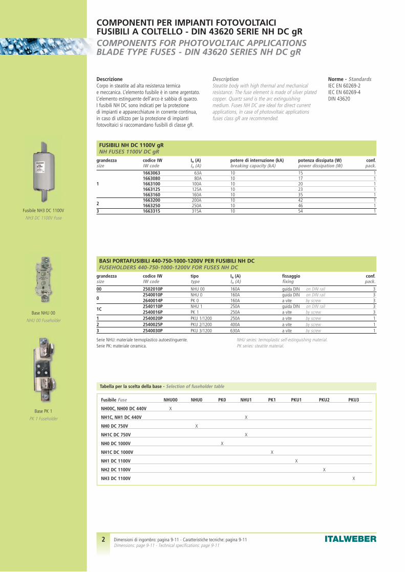
2 ITALWEBER
COMPONENTI PER IMPIANTI FOTOVOLTAICIFUSIBILI A COLTELLO - DIN 43620 SERIE NH DC gRCOMPONENTS FOR PHOTOVOLTAIC APPLICATIONSBLADE TYPE FUSES - DIN 43620 SERIES NH DC gR
BASI PORTAFUSIBILI 440-750-1000-1200V PER FUSIBILI NH DC FUSEHOLDERS 440-750-1000-1200V FOR FUSES NH DC
grandezza codice IW tipo In (A) fissaggio conf.size IW code type In (A) fixing pack.
00 2502010P NHU 00 160A guida DIN on DIN rail 3
02540010P NHU 0 160A guida DIN on DIN rail 32640014P PK 0 160A a vite by screw 32540110P NHU 1 250A guida DIN on DIN rail 31C2540016P PK 1 250A a vite by screw 3
1 2540020P PKU 1/1200 250A a vite by screw 12 2540025P PKU 2/1200 400A a vite by screw 13 2540030P PKU 3/1200 630A a vite by screw 1
DescrizioneCorpo in steatite ad alta resistenza termica e meccanica. L’elemento fusibile è in rame argentato.L’elemento estinguente dell’arco è sabbia di quarzo.I fusibili NH DC sono indicati per la protezione di impianti e apparecchiature in corrente continua,in caso di utilizzo per la protezione di impianti fotovoltaici si raccomandano fusibili di classe gR.
DescriptionSteatite body with high thermal and mechanical resistance. The fuse element is made of silver platedcopper. Quartz sand is the arc extinguishingmedium. Fuses NH DC are ideal for direct currentapplications, in case of photovoltaic applicationsfuses class gR are recommended.
Norme - StandardsIEC EN 60269-2IEC EN 60269-4DIN 43620
Fusibile Fuse NHU00 NHU0 PK0 NHU1 PK1 PKU1 PKU2 PKU3
NH00C, NH00 DC 440V X
NH1C, NH1 DC 440V X
NH0 DC 750V X
NH1C DC 750V X
NH0 DC 1000V X
NH1C DC 1000V X
NH1 DC 1100V X
NH2 DC 1100V X
NH3 DC 1100V X
Tabella per la scelta della base - Selection of fuseholder table
NHU series: termoplastic self-estinguishing material.PK series: steatite material.
Serie NHU: materiale termoplastico autoestinguente.Serie PK: materiale ceramica.
FUSIBILI NH DC 1100V gRNH FUSES 1100V DC gR
grandezza codice IW In (A) potere di interruzione (kA) potenza dissipata (W) conf.size IW code In (A) breaking capacity (kA) power dissipation (W) pack.
1663063 63A 10 15 11663080 80A 10 17 1
1 1663100 100A 10 20 11663125 125A 10 23 11663160 160A 10 35 1
21663200 200A 10 42 11663250 250A 10 46 1
3 1663315 315A 10 54 1Fusibile NH3 DC 1100V
NH3 DC 1100V Fuse
Base NHU 00
NHU 00 Fuseholder
Base PK 1
PK 1 Fuseholder
Dimensioni di ingombro: pagina 9-11 - Caratteristiche tecniche: pagina 9-11 Dimensions: page 9-11 - Technical specifications: page 9-11

3 ITALWEBER
COMPONENTI PER IMPIANTI FOTOVOLTAICIFUSIBILI CILINDRICI PER CORRENTE CONTINUACOMPONENTS FOR PHOTOVOLTAIC APPLICATIONSCYLINDRICAL FUSES FOR DIRECT CURRENT
DescrizioneFusibili cilindrici rapidi o extrarapidi con dimensioni10x38 mm o 14x51 mm per utilizzo all’interno di circuiti operanti in corrente continua.Per una efficace protezione delle stringhe degli impianti fotovoltaici si consiglia l’uso di fusibilicon caratteristica di intervento di tipo F o gR.
DescriptionFast or ultraquick cylindrical fuses with 10x38 mm or 14x51 mm dimensions, for use in direct current circuits. For an effective protection of the photovoltaic strings, it is advisable to use fuses with F or gR time-current characteristic.
Norme - StandardsIEC EN 60269IEC EN 60169-4
SERIE CH10 600V c.c. RAPIDI PER LA PROTEZIONE DI IMPIANTI FOTOVOLTAICICH10 600V d.c. FAST SERIES FOR PHOTOVOLTAIC APPLICATIONS
grandezza codice IW In (A) Vn (V) potere di interruzione (kA) resistenza nominale (Ω) conf.size IW code In (A) Vn (V) breaking capacity (kA) nominal resistance (Ω) pack.
1464001 1A 600 10 0,252 101464002 2A 600 10 0,124 101464004 4A 600 10 0,0511 101464006 6A 600 10 0,0261 10CH101464008 8A 600 10 0,0194 10(10,3x38 mm)1464010 10A 600 10 0,0128 101464012 12A 600 10 0,0103 101464015 15A 600 10 0,0078 101464020 20A 600 10 0,0045 10
SERIE CH10 900V c.c. gR PER LA PROTEZIONE DI IMPIANTI FOTOVOLTAICICH10 900V d.c. gR SERIES FOR PHOTOVOLTAIC APPLICATIONS
grandezza codice IW In (A) Vn (V) potere di interruzione (kA) potenza dissipata (W) conf.size IW code In (A) Vn (V) breaking capacity (kA) power dissipation (W) pack.
1463002 2A 900 30 1,50 101463004 4A 900 30 1,85 101463006 6A 900 30 2,50 10
CH10 1463008 8A 900 30 1,60 10(10,3x38 mm) 1463010 10A 900 30 2,15 10
1463012 12A 900 30 2,40 101463016 16A 900 30 3,00 101463020 20A 900 30 3,50 10
SERIE CH10 1000V c.c. gPV PER LA PROTEZIONE DI IMPIANTI FOTOVOLTAICICH10 1000V d.c. gPV SERIES FOR PHOTOVOLTAIC APPLICATIONS
grandezza codice IW In (A) Vn (V) potere di interruzione (kA) potenza dissipata (W) conf.size IW code In (A) Vn (V) breaking capacity (kA) power dissipation (W) pack.
1465002 2A 1000 30 1,00 101465004 4A 1000 30 1,25 101465006 6A 1000 30 1,65 101465008 8A 1000 30 1,90 10
CH10 1465010 10A 1000 30 2,30 10(10,3x38 mm) 1465012 12A 1000 30 2,40 10
1465016 16A 1000 30 2,50 101465020 20A 1000 30 3,25 101465025 25A 900 30 3,45 10
ApprovalOmologazione
Fusibile CH10 gR
CH10 gR Fuse
Fusibile CH10 gPV
CH10 gPV Fuse
Caratteristiche tecniche: pagina 10 Technical specifications: page 10

4 ITALWEBER
COMPONENTI PER IMPIANTI FOTOVOLTAICIFUSIBILI CILINDRICI E PORTAFUSIBILI PER CORRENTE CONTINUACOMPONENTS FOR PHOTOVOLTAIC APPLICATIONSCYLINDRICAL FUSES AND FUSEHOLDERS FOR DIRECT CURRENT
BASI SERIE PCF PER FUSIBILI CH10 600V, 900V O 1000V c.c.FUSEHOLDERS PCF SERIES FOR FUSES CH10 600V, 900V OR 1000V d.c.
tipo codice IW n. poli indicatore luminoso Vn max (V) In (A) conf.type IW code poles indicator light Vn max (V) In (A) pack.
PCF10 1x38 2401038D 1 – 1000 20 12PCF10 2x38 2402038D 2 – 1000 20 6PCF10 1x38/I 2411038D 1 LED 1000 20 12PCF10 2x38/I 2412038D 2 LED 1000 20 6
PINZE PER FUSIBILI CILINDRICIPLIERS FOR CYLINDRICAL FUSES
tipo codice IW per fusibili Pn max (W) Fissaggio conf.type IW code for fuses Pn max (W) Fixing pack.
HK1038V 0900504 CH10 4 a vite by screw 250HK10383 0900502 CH10 4 a saldare to be welded 250HK1451V 0900505 CH14 6 a vite by screw 250HK1451S 0900506 CH14 6 a saldare to be welded 250
SERIE CH14 700V c.c. aR PER LA PROTEZIONE DI IMPIANTI IN CORRENTE CONTINUACH14 700V d.c. aR SERIES FOR DIRECT CURRENT APPLICATIONS
grandezza codice IW In (A) Vn (V) potere di interruzione (kA) potenza dissipata (W) conf.size IW code In (A) Vn (V) breaking capacity (kA) power dissipation (W) pack.
1489005 5A 700 50 1,5 101489010 10A 700 50 4,0 101489015 15A 700 50 5,5 101489020 20A 700 50 6,0 10CH141489025 25A 700 50 7,0 10(14x51 mm)1489030 30A 700 50 9,0 101489032 32A 700 50 7,6 101489040 40A 700 50 8,0 101489050 50A 700 50 9,0 10
Warning: the PCF fuseholders cannot be open under load (DC-20 category).
Warning: pls. check power dissipation values. Maximun admitted values of fuseholders are often very low.
Attenzione: i portafusibili non sono sezionabili sotto carico (categoria DC-20).
Prestare attenzione alle potenze dissipate. I portafusibili hanno valori massimiammissibili spesso molto bassi.
DescrizioneI portafusibili sezionabili PCF per fusibili 10x38 mm,per utilizzo in corrente continua fino a 1000V possonoanche ospitare un fusibile di scorta. Per una efficaceprotezione delle stringhe degli impianti fotovoltaici si consiglia l’uso di fusibili con caratteristica di intervento di tipo F o gR.Le pinze portafusibili costituiscono una soluzione alternativa, ideale per l’uso su circuiti stampati.
DescriptionThe PCF fuseholders for 10x38 mm fuses can be usedin direct current up to 1000V. They can also host a backup fuse. For an effective protection of the photovoltaic strings, it is advisable to use fuses with F or gR time-current characteristic. The fuse pliers can be an alternative solution, ideal for use on printed circuit boards.
Norme - StandardsIEC EN 60947-1IEC EN 60947-3
Portafusibilesezionabile PCF10 2x38
PCF10 2x38Fuseholder
Fusibile CH14 aR
CH14 aR Fuse
Pinze per fusibili cilindrici
Pliers for cylindrical fuses
Dimensioni di ingombro: pagina 11 - Caratteristiche tecniche: pagina 11 Dimensions: page 11 - Technical specifications: page 11

5 ITALWEBER5 ITALWEBER
COMPONENTI PER IMPIANTI FOTOVOLTAICIINTERRUTTORI SEZIONATORI PER CORRENTE CONTINUACOMPONENTS FOR PHOTOVOLTAIC APPLICATIONSSWITCH DISCONNECTORS FOR DIRECT CURRENT APPLICATIONS
DescrizioneInterruttori sezionatori per corrente continua, in versione quadripolare (vedere gli schemi diconnessione dei morsetti a pagina 12.Particolarmente indicati per il sezionamento negli impianti fotovoltaici.N.B. Per un corretto utilizzo in corrente continua,si raccomanda la consultazione della tabella tecnica a pagina 12.
DescriptionSwitch-disconnectors for direct current application.The poles must be connected inseries (see page 12for the connection schemes). They are the perfectsolution for disconnecting the strings in photovoltaic plants. N.B. For a correct use of them, please consult the technical table on page 12
Norme - StandardsIEC EN 60947-3IEC EN 60364-7-712
INTERRUTTORE SEZIONATORE W80-00 4 POLI 800V c.c. 12,5A CATEGORIA DI UTILIZZO DC-21BSWITCH DISCONNECTOR W80-00 4 POLES 800V d.c. 12,5A UTILISATION CATEGORY DC-21B
tipo codice IW descrizione conf.type IW code description pack.
W80-00 3450080 corpo sezionatore (connessione a morsetto) switch disconnector body (clamp terminals) 1DS-EI01 3591201 manovra diretta direct handle 1DS-EN01 3591101(1) manovra rinviata esterna nera black interlock handle 1DS-ER01 3591111(1) manovra rinviata esterna giallo/rossa yellow/red interlock handle 1
INTERRUTTORE SEZIONATORE W160-0 4 POLI 800V c.c. 50A CATEGORIA DI UTILIZZO DC-21BSWITCH DISCONNECTOR W160-0 4 POLES 800V d.c. 50A UTILISATION CATEGORY DC-21B
tipo codice IW descrizione conf.type IW code description pack.
W160-0 3450160 corpo sezionatore (connessione a morsetto) switch disconnector body (clamp terminals) 1DS-EI01 3591201 manovra diretta direct handle 1DS-EN01 3591101(1) manovra rinviata esterna nera black interlock handle 1DS-ER01 3591111(1) manovra rinviata esterna giallo/rossa yellow/red interlock handle 1DS-DN01 3591520 supporto aggancio guida DIN DIN rail support 1
INTERRUTTORE SEZIONATORE W250-1 4 POLI 800V c.c. 175A CATEGORIA DI UTILIZZO DC-22ASWITCH DISCONNECTOR W250-1 4 POLES 800V d.c. 175A UTILISATION CATEGORY DC-22A
tipo codice IW descrizione conf.type IW code description pack.
W250-1 3450250 corpo sezionatore (connessione a bullone) switch disconnector body (screw connection) 1DS-EI11 3591203 manovra diretta direct handle 1DS-EN11 3591103(1) manovra rinviata esterna nera black interlock handle 1DS-ER11 3591113(1) manovra rinviata esterna giallo/rossa yellow/red interlock handle 1DS-PI11 3591503 ponticelli di connessione set 2 pz. connection device 1DS-CU12 3591513 calotta prezione terminali terminal protective cover 1
INTERRUTTORE SEZIONATORE W630-2 4 POLI 800V c.c. 280A CATEGORIA DI UTILIZZO DC-22ASWITCH DISCONNECTOR W630-2 4 POLES 800V d.c. 280A UTILISATION CATEGORY DC-22A
tipo codice IW descrizione conf.type IW code description pack.
W630-2 3450630 corpo sezionatore (connessione a bullone) switch disconnector body (screw connection) 1DS-EI21 3591204 manovra diretta direct handle 1DS-EN21 3591104(1) manovra rinviata esterna nera black interlock handle 1DS-ER21 3591114(1) manovra rinviata esterna giallo/rossa yellow/red interlock handle 1DS-PI21 3591504 ponticelli di connessione set 2 pz. connection device 1DS-CU22 3591514 calotta prezione terminali terminal protective cover 1
INTERRUTTORE SEZIONATORE W800-3 4 POLI 800V c.c. 625A CATEGORIA DI UTILIZZO DC-22ASWITCH DISCONNECTOR W800-3 4 POLES 800V d.c. 625A UTILISATION CATEGORY DC-22A
tipo codice IW descrizione conf.type IW code description pack.
W800-3 3450800 corpo sezionatore (connessione a bullone) switch disconnector body (screw connection) 1DS-EI31 3591205 manovra diretta direct handle 1DS-EN31 3591105(1) manovra rinviata esterna nera black interlock handle 1DS-ER31 3591115(1) manovra rinviata esterna giallo/rossa yellow/red interlock handle 1
ACCESSORIACCESSORIES
tipo codice IW descrizione conf.type IW code description pack.
D5LAU01 3591401 contatti ausiliari 1NA + 1NC auxiliary contacts 1NA + 1NC 1D5LAU02 3591411 contatti ausiliari 2NA + 2NC auxiliary contacts 2NA + 2NC 1
(1) Shaft extension included(1) Completa di albero di comando
Interruttore sezionatore W80-00
W80-00 switch disconnector
Interruttore sezionatore W160-0
W160-0 switch disconnector
Interruttore sezionatore W250-1
W250-1 switch disconnector
Interruttore sezionatore W630-2
W630-2 switch disconnector
Interruttore sezionatore W800-3
W800-3 switch disconnector
Dimensioni di ingombro: pagina 12 - Caratteristiche tecniche: pagina 12 Dimensions: page 12 - Technical specifications: page 12

6 ITALWEBER6 ITALWEBER
COMPONENTI PER IMPIANTI FOTOVOLTAICILIMITATORI DI SOVRATENSIONE E CONNETTORICOMPONENTS FOR PHOTOVOLTAIC APPLICATIONSSURGE ARRESTERS AND CONNECTORS
Norme - StandardsIEC EN 61643-1
Norme - StandardsIEC EN 61215IEC EN 61730
DescrizioneLimitatori di sovratensione in classe II per uso incorrente continua. Utilizzabili negli impianti fotovoltaicifino a tensioni di 1000V c.c. Corrente di scarica nominale:20kA (onda 8/20) e corrente di scarica massima: 40kA(onda 8/20). Per montaggio su guida DIN.
DescriptionClass II surge arrester for use in direct currentapplications. Ideal solution for protection of photovoltaicplants up to 1000V dc. Nominal discharge current: 20kA(8/20 wave) and maximum discharge current: 40kA (8/20wave). DIN rail mounting.
DescrizioneConnettori. Il sistema di interconnessione è compatibilecon la maggior parte dei tipi di connettori utilizzati nelleapplicazioni fotovoltaiche. Il sistema di sgancio è del tipo“elastic trigger” ed è stato studiato per evitare sganciaccidentali.
DescriptionConnectors. The interconnection system is compatiblewith most types of connectors used in the photovoltaicapplication. The release system is of the "elastic trigger"type and has been studied to avoid an accidental release.
LIMITATORI DI SOVRATENSIONE A VARISTORI E SPINTEROMETRI (GDT) 580V c.c.SURGE ARRESTERS WITH VARISTORS AND GAS DISCHARGE TUBE (GDT) 580V d.c.
tipo codice IW n. varistori n. GDT n. moduli Vn (V) Up (kV) conf.type IW code varistors n. GDT moduls Vn (V) Up (kV) pack.
ETITEC C 440/20 2+0 2441532 2 – 2 580V c.c. < 2,2 1ETITEC C 440/20 2+0 RC 2441533(1) 2 – 2 580V c.c. < 2,2 1ETITEC C 255/20 G GDT 2441910 – 1 1 255V c.c. < 1,2 1
(1) RC = with remote control(1) RC = con controllo remoto
LIMITATORI DI SOVRATENSIONE A VARISTORI 550V c.c. E 1000V c.c.SURGE ARRESTERS WITH VARISTORS 550V d.c. AND 1000V d.c.
tipo codice IW n. varistori n. moduli Vn (V) Up (kV) conf.type IW code varistors moduls Vn (V) Up (kV) pack.
ETITEC C 550/20 2445207 2 2 550V c.c. < 2,1 1ETITEC C 1000/20 2445208 3 3 1000V c.c. < 4,0 1ETITEC C 550/20 RC 2445210(1) 2 2 550V c.c. < 2,1 1ETITEC C 1000/20 RC 2445211(1) 3 3 1000V c.c. < 4,0 1
moduli varistore varistor modulesmodulo varistore 550V 2445222 2 2 550V c.c. < 2,1 1modulo varistore 1000V 2445223 3 3 1000V c.c. < 4,0 1
(1) RC = with remote control(1) RC = con controllo remoto
CONNETTORI 1000V c.c. IP67CONNECTORS 1000V d.c. IP67
tipo codice IW descrizione ø pin sez. cavo ø foro pannello conf.type IW code description ø pin cable sect. ø panel hole pack.
CSP-2 M 1002700 Connettore da parete maschio (-) Panel connector male (-) 4 mm 6 mm2 13,4 mm 100CSP-2 F 1002710 Connettore da parete femmina (+) Panel connector female (+) 4 mm 6 mm2 13,4 mm 100CSC-2 M 1002720 Connettore volante maschio (-) Cable connector male (-) 4 mm 6 mm2 – 100CSC-2 F 1002730 Connettore volante femmina (+) Cable connector female (+) 4 mm 6 mm2 – 100– 1002750 Pinza di crimpatura Hand crimp tool 4 mm 4 o 6 mm2 – 1
Material: PC PolycarbonateFlame class: UL94 V0Temperature range: -40° +90°External cable diameter: 5,7mm ÷ 7,2 mm
Materiale: PC PolicarbonatoClasse estinguenza: UL94 V0Temperatura di esercizio: -40° +90°Diametro Cavo esterno: 5,7mm ÷ 7,2 mm
Limitatore di sovratensioneETITEC C 1000/20 RC
ETITEC C 1000/20 RCsurge arrester
Connettori CSP-2
CSP-2 connectors
Pinza di crimpatura
Hand crimp tool
Limitatore di sovratensioneETITEC C 255/20 G GDT
ETITEC C 255/20 G GDTsurge arrester
Caratteristiche tecniche: pagina 13 Technical specifications: page 13

7 ITALWEBER
CENTRALINI DA PARETE IP65IP65 WALL MOUNTING CABINETS
tipo codice IW descrizione dimensioni (H x L x P) mm conf.type IW code description dimension (H x L x P) mm pack.
CT 14508 7000101 4/8 moduli 4/8 moduls 215 x 200 x 105 1CT 14512 7000110 6/12 moduli 6/12 moduls 290 x 240 x 105 1CT 14504 7000120 14/24 moduli 14/24 moduls 300 x 400 x 140 1
Plain size, excellent resistance in any point. Horizontal inspection door inpolycarbonate. DIN rail, plag for screw for double insulation and separatingplag are included.
Pareti lisce, massima robustezza in ogni punto. Sportello apertura orizzontalein Policarbonato trasparente ambrato. Completi di guida DIN, tappi coprivitiper doppio isolamento e tappo separatore.
Centralino CT14508
CT14508 Cabinet
COMPONENTI PER IMPIANTI FOTOVOLTAICIQUADRI PER PROTEZIONE SEZIONAMENTO E PARALLELO STRINGHECOMPONENTS FOR PHOTOVOLTAIC APPLICATIONSPANELS FOR STRINGS PARALLEL CONNECTION, PROTECTION AND DISCONNECTION
DescrizioneQuadri di parallelo, protezione e sezionamento dellestringhe degli impianti fotovoltaici. I fusibili di protezionevanno ordinati a parte. Il cablaggio del quadro è su richiesta. I prodotti sotto riportati costituisconounicamente degli esempi applicativi.N.B. Possiamo realizzare quadri su disegno e specifiche del cliente.
DescriptionPanels for photovoltaic strings parallel connection,protection and disconnection. The protection fusesmust be ordered separately. The cabling of the panelis on request. The below indicated products are only examples. N.B. We can make panels according to customer drawings and specifications.
QUADRI PROTEZIONE E PARALLELO PER 2, 4 O 6 STRINGHEPANELS FOR PARALLEL CONNECTION AND PROTECTION OF 2, 4 OR 6 STRINGS
tipo codice IW n. portafusibili In (A) Vn (V) dimensioni conf.(H x L x P) mm
type IW code fuseholders In (A) Vn (V) dimension pack.(H x L x P) mm
2 stringhe 2 strings 7852020 2 x PCF10 2x38 20 1000V c.c. 215 x 200 x 105 14 stringhe 4 strings 7853020 4 x PCF10 2x38 20 1000V c.c. 290 x 240 x 105 16 stringhe 6 strings 7854020 6 x PCF10 2x38 20 1000V c.c. 300 x 400 x 140 1
N. 1 varistor surge arrester type ETITEC C 1000/20 RC is included in all versionsProtection degree: IP 65
Tutte le versioni comprendono n. 1 scaricatore a varistori 1000V c.c.tipo ETITEC C 1000/20 RCGrado di protezione: IP 65
QUADRI PROTEZIONE, SEZIONAMENTO E PARALLELO PER 8 O 12 STRINGHEPANELS FOR PARALLEL CONNECTION, PROTECTION AND DISCONNECTION OF 8 OR 12 STRINGS
tipo codice IW n. portafusibili sezionatore In (A) Vn (V) dimensioni conf.(H x L x P) mm
type IW code fuseholders switch In (A) Vn (V) dimension pack.disconnector (H x L x P) mm
8 stringhe 8 strings 7855020 16 x PCF10 1x38 W160-0 50A 800V c.c. 570 x 380 x 185 112 stringhe 12 strings 7856020 24 x PCF10 1x38 W250-1 175A 800V c.c. 570 x 380 x 185 1
N. 1 varistor surge arrester type ETITEC C 1000/20 RC is included in all versionsProtection degree: IP 65
N.B. Fuses must be ordered separately, see on page 3
Tutte le versioni comprendono n. 1 scaricatore a varistori 1000V c.c.tipo ETITEC C 1000/20 RCGrado di protezione: IP 65
N.B. I fusibili non sono inclusi, per la scelta vedi pagina 3
Quadro 2 stringhe
2 strings panel
Quadro 8 stringhe
8 strings panel

8 ITALWEBER
ESEMPI EXAMPLES
COMPONENTI PER IMPIANTI FOTOVOLTAICIQUADRI PER PROTEZIONE SEZIONAMENTO E PARALLELO STRINGHECOMPONENTS FOR PHOTOVOLTAIC APPLICATIONSPANELS FOR STRINGS PARALLEL CONNECTION, PROTECTION AND DISCONNECTION
12 stringhe12 strings
3 stringhe3 strings
2 stringhe2 strings
2 stringhe2 strings
4 stringhe4 strings

9 ITALWEBER9 ITALWEBER9 ITALWEBER
FUSIBILI SERIE “C”SERIES "C" FUSES
Caratteristiche tecniche - Technical specifications
p
FUSIBILI SERIE NH DC 440V, 750V E 1000VSERIES NH DC 440V, 750V AND 1000V FUSES
Dimensioni in mm e caratteristiche tecniche - Dimensions in mm and technical specifications
tipo dimensioni - dimensionstype A B C D E F G H K
00C 79 53 47 35 15 21 52 7,5 600 79 53 47 35 15 28 56 12,0 61C 135 68 65 40 15 28 61 12,0 61 135 72 65 40 20 46 65 14,0 6
NH DC 440V
tipo dimensioni - dimensionstype A B C D E F G H K I
0 125 72 66 50 30 15 60 10 6 351C 135 72 66 55 30 15 65 10 6 40
C
B
A
E
F
I G
H
D
NH DC 750V NH DC 1000V
Caratteristiche d’intervento tempo-correnteTime-current characteristics
tipo dimensioni - dimensionstype A B C E G P R M O
1 194 24 40 46 61,5 20,5 13,7 50 462 209 30 48 54 71,0 27,3 16,2 59 543 209 37 60 64 82,0 35,6 17,0 70 64
NH DC 1100V
DIMENSIONI E CARATTERISTICHE TECNICHEFUSIBILI SERIE NH DC gR
DIMENSIONS AND TECHNICAL SPECIFICATIONSSERIES NH DC gR FUSES

10 ITALWEBER
FUSIBILI SERIE “C”SERIES "C" FUSES
Caratteristiche tecniche - Technical specifications
DIMENSIONI E CARATTERISTICHE TECNICHEFUSIBILI EXTRARAPIDI SERIE CHDIMENSIONS AND TECHNICAL SPECIFICATIONSSERIES CH ULTRAQUICK FUSES
FUSIBILI CILINDRICI EXTRARAPIDI SERIE CH c.c.SERIES CH d.c. gR/aR ULTRAQUICK FUSES
Caratteristiche tecniche - Technical specifications
CH10 gR 600V c.c. CH10 gr 900V c.c.
CH10 gPV 1000V c.c. CH14 aR 700V c.c.
Caratteristiche d’intervento tempo-correnteTime-current characteristics
Caratteristiche d’intervento tempo-correnteTime-current characteristics

11 ITALWEBER11 ITALWEBER
PORTAFUSIBILI SERIE NHU PK PKU PCF10 E PINZESERIES NHU PK PKU PCF10 FUSEHOLDERS AND PLIERS
tipo dimensioni - dimensionstype A B C D E F G H
HK1038V 13,0 14,0 18,0 4,2 5,0 – – –HK10383 12,3 9,8 19,0 2,0 2,0 0,75 11,0 4,0HK1451V 16,0 16,0 23,0 4,2 6,5 – – –HK1451S 16,0 14,0 15,5 5,0 3,5 0,75 11,0 4,0
Pinze Pliers
Fissaggio a viteFixing by screw
Fissaggio a saldareFixing to be welded
Portafusibili PCF10 Fuseholders PCF10
Dimensioni in mm - Dimensions in mm
tipo dimensioni - dimensionstype A B C D E F G H K L M N O P Q
NHU00 120 100 37 20 86 58,0 23,0 56,5 84,5 146 M8 25 – 7,5 15,0NHU0 170 150 47 24 122 63,0 29,0 74,0 91,5 185 M8 25 – 7,5 15,0PK0 170 150 33 20 130 60,0 4,5 74,0 – – M8 25 – 7,5 –NHU1 200 175 60 28 148 77,5 35,0 80,0 123,0 250 M10 25 30 10,5 20,5PK1 200 175 55 26 141 81,0 10,0 80,0 – – M10 25 – 10,5 –PKU 1/1200 – 232 56 25 – 84,5 10,0 140,0 – – M10 – – 17,5 –PKU 2/1200 – 257 64 30 – 100,0 10,0 140,0 – – M10 – – 17,5 –PKU 3/1200 – 270 68 40 – 103,0 10,0 140,0 – – M12 – – 25,0 –
M
BHENA
C
D
P
G
K
F
tipo PK PKUtype PK PKU
D
PQ
ABNO
C
P
D
C
øø Q
ABN
FG
MHL E
K
tipo NHUtype NHU
tipo NHU00 e 0type NHU00 and 0
tipo NHU1type NHU1
DIMENSIONI E CARATTERISTICHE TECNICHEBASI PORTAFUSIBILI PER FUSIBILI NH E CILINDRICIDIMENSIONS AND TECHNICAL SPECIFICATIONSFUSEHOLDERS FOR NH AND CYLINDRICAL FUSES

12 ITALWEBER12 ITALWEBER
INTERRUTTORI SEZIONATORI PER CORRENTE CONTINUASWITCH DISCONNECTORS FOR DIRECT CURRENT APPLICATIONS
Caratteristiche tecniche e dimensioni in mm - Technical specifications and dimensions in mm
DIMENSIONI E CARATTERISTICHE TECNICHEINTERRUTTORI SEZIONATORI PER CORRENTE CONTINUADIMENSIONS AND TECHNICAL SPECIFICATIONSSWITCH DISCONNECTORS FOR DIRECT CURRENT APPLICATIONS
W160-0 Foratura pannello Drilling template
W250-1 Foratura pannello Drilling template
W630-2 Foratura pannello Drilling templateW800-3
tipo Type A C E F G H I J K L M N O R (max) R (min) øP øTW630-2 275 65 130 145 160 205 235 30 290 245 5 30 121 119 18 6,5 M10W800-3 325 75 150 175 190 250 290 40 340 285 8 39 137 108 18 9 M14
W80-00 Foratura pannello Drilling template
Tipo Type W80-00 W160-0 W250-1 W630-2 W800-3Tensione di isolamento (V) 800 1000 1000 1000 1000Insulating voltage (V)Tensione di impulso (kV) 8 8 8 12 12Impuls withstand voltage (kV)
48V DC23A 80A DC23A 160A DC23A 250A DC23A 630A DC23A 800A
Classe di impiego, 110V DC23A 80A DC23A 160A DC23A 250A DC23A 630A DC23A 800A
correnti e tensioni nominali 230V DC23A 63A DC23A 125A DC23A 250A DC23A 630A DC23A 800A
per utilizzo in c.c. 400V DC22A 15A DC22A 50A DC23A 200A DC23A 500A DC23A 630A500V DC21B 25A DC21B 85A DC23A 200A DC23A 500A DC23A 630A
Utilization category, 600V DC21B 20A DC21B 65A DC22A 190A DC22A 300A DC22A 835A
rated current and voltages 750V DC21B 15A DC21B 55A DC22A 185A DC22A 300A DC22A 670A
for d.c. applications 800V DC21B 12,5A DC21B 50A DC22A 175A DC22A 280A DC22A 625A850V DC20A – DC21B 45A DC22A 175A DC22A 270A DC22A 550A900V DC20A – DC21B 40A DC22A 125A DC22A 270A DC22A 500A
Corrente di corto circuito max (kA picco)Max shorts circuit current (kA peack) 5 10 14 26 60
Schemi di connessioneConnection diagram

13 ITALWEBERITALWEBER13
Tipo Type ETITEC C 255/20G ETITEC C 440/20Normativa Standard IEC 61643-1Categoria IEC/VDE IEC/VDE category II / CMax tensione operativa (AC/DC) Uc Max operating voltage (AC/DC) Uc 255 / 255 V 440 / 580 VCorrente di scarica nominale (8/20) In Nominal discharge current (8/20) In 20 kAMax corrente di scarica (8/20) Imax Max discharge current (8/20) Imax 40 kALivello di protezione a In (8/20) Protection level at In (8/20) – 2,2 kVLivello di protezione a In (1,5/50) Protection level at In (1,5/50) 1,2 kV –Tempo di risposta Response time <100 ns <25 nsCorrente residua alla Uc IPE Residual current at Uc IPE 0 <1,5 mATorsione Torque max 4,5 NmFusibile di back-up (se alim. >125A) Back-up fuse (if mains >125A) – 125A gGTemperatura operativa Temperature range da -40°C a + 80°CSezione cavi Connection cable section max 25 mm2
Montaggio Mounting interno su guida DIN internal on DIN railGrado di protezione Protection degree IP 20Materiale corpo Casing material termoplastico UL94-V0 thermoplastic UL94-V0
Dati aggiuntivi per contatto di segnalazione ETITEC C-RC Additional data for remote control ETITEC C-RCDati elettrici contatto Switching data AC: 250V / 0,5A; 125V / 3ASezione cavi Connection cable section max 1,5 mm2
Torsione Torque max 0,25 Nm
Tipo Type ETITEC C 550/20 ETITEC C 1000/20Normativa Standard IEC 61643-1Categoria IEC/VDE IEC/VDE category II / CMax tensione operativa (DC) Uc Max operating voltage (DC) Uc 550V DC 1000V DCCorrente di scarica nominale (8/20) In Nominal discharge current (8/20) In 20 kAMax corrente di scarica (8/20) Imax Max discharge current (8/20) Imax 40 kALivello di protezione a In (8/20) Protection level at In (8/20) <2,1 kV <4,0 kVTempo di risposta Response time <25 nsCorrente residua alla Uc IPE Residual current at Uc IPE <1,5 mATorsione Torque max 4,5 NmFusibile di back-up (se alim. >125A) Back-up fuse (if mains >125A) 125A gGTemperatura operativa Temperature range da -40°C a + 80°CSezione cavi Connection cable section max 25 mm2
Montaggio Mounting interno su guida DIN internal on DIN railGrado di protezione Protection degree IP 20Materiale corpo Casing material termoplastico UL94-V0 thermoplastic UL94-V0
Dati aggiuntivi per contatto di segnalazione ETITEC C-RC Additional data for remote control ETITEC C-RCDati elettrici contatto Switching data AC: 250V / 0,5A; 125V / 3ASezione cavi Connection cable section max 1,5 mm2
Torsione Torque max 0,25 Nm
LIMITATORI DI SOVRATENSIONE TIPO ETITEC CSURGE ARRESTERS ETITEC C TYPE
Caratteristiche tecniche - Technical specifications
CARATTERISTICHE TECNICHELIMITATORI DI SOVRATENSIONETECHNICAL SPECIFICATIONSSURGE ARRESTERS
ETITEC C 2+0 RC
ETITEC C 550/20 RC ETITEC C 1000/20 RC
ETITEC C 255/20GSchemi di collegamento Connection diagrams
Schemi di collegamento Connection diagrams
ITALWEBER SPA si riserva la facoltà di apportare modifiche e/o migliorie ai prodotti del presente catalogosenza l’obbligo di darne preavviso.Stampa: ARTI GRAFICHE COLOMBO sas - Muggiò (MI)
ITALWEBER SPA has the right to change and/orimprove the products included in this cataloguewithout any notice.Printing: ARTI GRAFICHE COLOMBO - Muggiò (MI)

Serie RBCARATTERISTICHE
Dissipatore ad alta conducibilità termica.Profilo del radiatore progettato per la massima dissipazione del calore, sia con ventilazione naturale che forzata.Trattamento superficiale che garantisce un’ottima resistenza agli urti ed agli agenti chimici esterni.Protezione dell’elemento resistivo realizzato con resina termoindurente che, per l’elevata conduttività termica e la minima distorsione, è adatta a sopportare alte temperature.Avvolgimento realizzato con uniformità di passo e massima copertura dell’intero supporto, per ottenere un alto fattore dissipativo. Supporto rettificato per permettere la massima uniformità di avvolgimento.Marcatura sulla sommità del radiatore per una facile identificazione dopo il montaggio.Realizzazione di tutte le connessioni mediante puntatura elettrica.
RESISTORI A FILO IN DISSIPATOREDI ALLUMINIO DA 10 W A 250 W
SpecificheSPECIFICHE ELETTRICHE
- Valori ohmiciSerie E24. Per valori inferiori o superiori alla Gamma Valori consultare il costruttore.- TolleranzaStandard 5%. Disponibili su richiesta tolleranze fino a 1%.- Coefficiente di temperatura±30 ppm R > 20 Ohm±50 ppm 1 Ohm < R < 20 Ohm±100 ppm 0.1 Ohm < R < 1 Ohm- Rigidità dielettrica1500 Vac per il tipo RB102500 Vac per i tipi RB25 e RB503500 Vac per i tipi RB75, RB101, e RB1504500 Vac per i tipi RB100 E RB250- Resistenza di isolamento10000 MOhm minimo1000 MOhm dopo le prove di umidità.- Sovraccarico5 secondi a 5 volte la potenza nominale.- Non induttiviAvvolgimenti non induttivi con metodo Ayrton-Perry
SPECIFICHE MECCANICHE- Sforzo sui terminali6 Kg alla trazione; 3 Nm per RB100 e 4 Nm per RB250 alla torsione.- SaldabilitàIn accordo con il metodo 208 MIL-STD-202L’uso di stagno per alte temperature è indispensabile quando i resistori vengono utilizzati a potenze vicine a quella nominale.
MATERIALI- SupportoSteatite o allumina rettificato.- Elemento resistivoLeghe in rame-nichel o nichel-cromo con coefficiente di temperatura determinato.- CapsuleAcciaio inox.- IncapsulanteResina epossidica per alte temperature (molded)-DissipatoreAlluminio anodizzato- TerminaliCopperweld da RB10 a RB150.Acciaio inox per RB100 e RB250.
DERATINGQuesti resistori possono essere impiegati con temperature da -55°C a +250°C.Per utilizzarli a temperature ambiente maggiori di 25°C occorre tener conto di una riduzione di potenza con derating lineare da piena potenza a zero a 250°C.
Questi resistori eguagliano o eccedono quanto specificato nella MIL - PRF - 18546 G.
SERIE RB 9IT 2010Resistori a filo in dissipatore
di alluminio da 10 W a 250 W
RB10
RB25
RB50
RB75
RB101
RB150
RB100
RB250
RE65
RE70
RE75
-
-
-
RE77
RE80
12
25
50
75
100
150
150
250
6
12.5
20
35
40
55
75
100
0.01-10K
0.01-18K
0.01-68K
0.1-50K
0.1-70K
0.1-100K
0.1-100K
0.1-120K
265
550
1250
1400
1900
2500
1900
2300
5.1
3
1.9
1.1
1
1
0.84
0.66
6
14
35
85
115
165
500
900
415x1
535x1
930x1.5
995x3
995x3
995x3
930x3
930x3
Tipo ATETipo
MIL-PRF-18546 G
Potenza Nom.(W)
Pmax senza pannello
(W)
Aum.Temp. con pannello
(W)
GammaValori(Ohm)
TensioneLimite
(V)
Peso
(g)
Dimensioni Pannello
(cm² x mm)

Tipo ATE A B C D E F G H J K L M N ØDimensioni (mm)
RB10 20.4
27.2
29.2
47
47
47
71.5
76
±0.2
35
49
71
73
89
122
139
178
±1
10
14
16
24
24
24
44.5
55.6
±0.2
11
14
16
27
27
27
46
54
±0.2
2.4
4.4
5.2
9.5
14.5
19.5
9.6
7.8
±0.5
2
2
2
3.5
3.5
3.5
5
6.3
±0.2
2
2
2
3
3
3
M5
M6
±0.2
2.2
2.2
2.2
3.2
3.2
3.2
-
-
±0.2
2.4
3.2
3.2
4.4
4.4
4.4
4.8
4.8
±0.2
-
-
-
-
-
-
69.8
98.4
±0.2
15.9
19.8
21.5
37
37
37
57.1
63.5
±0.2
5
6.5
7
11.5
11.5
11.5
20
25.5
±0.2
19
27
50
48
64
97
89
114
±0.5
14.3
18.3
39.7
29
35
58
-
76.2
±0.2
RB25
RB50
RB75
RB101
RB150
RB100
RB250
Toll.
D
C
H K
J F
M
E
B
N
solo RB250
RB100 - RB250
F
L
G A
solo RB250
NRB75 - RB101 - RB150
J F
E
B
G A
∅
Lsolo RB150
HC
K
D
= =
HC
K
D
J F
E
B
N
G A
L
∅
RB10 - RB25 - RB50
solo RB150
SERIE RB10 IT 2010Resistori a filo in dissipatoredi alluminio da 10 W a 250 W

Serie RB106
RESISTORI A FILO DI POTENZA INDISSIPATORE DI ALLUMINIO AD ALTOISOLAMENTO SUPERFICIALE
SPECIFICHE ELETTRICHE- Valori ohmiciSerie E24. Per valori inferiori o superiori alla Gamma Valori consultare il costruttore- TolleranzaStandard 5%. Disponibili su richiesta tolleranze fino a 1%- Coefficiente di temperaturaDa ±100 a ±30 ppm da R10 a Rmax- Rigidità dielettrica5000Vac / 7000Vac picco- Distanza di isolamento superficialeRB106 > 22mmRB256 > 25 mm- Resistenza di isolamento10000 MOhm minimo1000 MOhm dopo le prove di umidità- Sovraccarico5 secondi a 5 volte la potenza nominale- Non induttiviAvvolgimenti non induttivi con metodo Ayrton-Perry
Questi resistori eguagliano o eccedono quanto specificato nella MIL - PRF - 18546 G
Altri dati tecnici come per RB100 e RB250 standard
Tipo ATE Tipo MILPRF-18546 G
Potenza Nom.(W)
GammaValori(Ohm)
TensioneLimite(V)
Peso(g)
Dimensioni Pannello(cm² x mm)
RB106
RB256
RE77
RE80
150
250
0.1 - 100K
0.1 - 120K
1900
2300
500
900
930 x 3
930 x 3
Tipo ATE Dimensioni (mm)A B C D E F G H J K P Q R S T V Z
57.1 46 71.5 44.5 20 5 69.8 89 139 4.8 - -
- - -
25 9.6 M5 32 12
63.5 54 76 55.6 25.5 6.3 98.4 114 178 4.8 22.2 76.2 32 7.8 M6 32 16
±0.2 ±0.2 ±2 ±0.2 ±0.2 ±0.2 ±0.2±0.5 ±0.5 ±0.5 ±0.5 ±0.5 ±0.5 ±0.5
RB106
RB256
Toll.
SERIE RB10614 IT 2010RB106RB256
Resistori a filo di potenza in dissipatoredi alluminio ad alto isolamento superficiale
GQ
PS
HR
J
Z
ØV
K
A
T
2 Dadi 1 Rondella 1 Grover
RB106 - RB256
DE
F
CB

VRLABatteries
January 2012
Productoverview
VRLA Batteries Overview
pbq®
Leadinginquality
Model Nominal voltage (V) Capacity L (mm) W (mm) H (mm) H (incl. terminals
mm)Weight (Approx)
kg Terminals
pbq 33-12 GEL 12 33 195 130 155 180.0 10.2 M6
pbq 40-12 GEL 12 40 197 165 170 175.0 13.8 M6
pbq 60-12 GEL 12 60 250 160 178 200.0 19.8 M6
pbq 95-12 GEL 12 95 306 169 211 233 27 M8
pbq 100-12 GEL 12 100 330 171 214 224 30.5 M8
pbq 110-12 GEL 12 110 281 267 207 210 32.5 M8
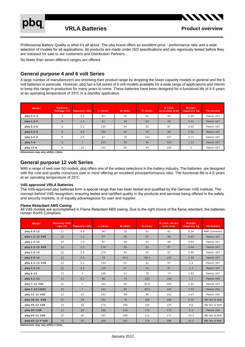
VRLABatteries
January 2012
Productoverview
Generalpurpose4and6voltSeriesA large number of manufacturers are shrinking their product range by dropping the lower capacity models in general and the 6 volt batteries in particular. However, pbq has a full series of 6 volt models available for a wide range of applications and intents to keep this range in production for many years to come. These batteries have been designed for a functional life of 4-5 years at an operating temperature of 25oC in a standby application.
Model Nominal Voltage (V) Capacity (Ah) L (mm) W(mm) H (mm)
H (incl. terminals mm)
Weight (Approx) kg Terminals
pbq 3.5-4 4 3.5 91 35 61 64 0.49 Faston 187
pbq 1.2-6 6 1.2 97 24 52 58 0.31 Faston 187
pbq 3.2-6 6 3.2 134 34 61 67 0.65 Faston 187
pbq 3.5-6 6 3.5 194 25 50 56 0.62 Faston 187
pbq 4.5-6 6 4.5 47 70 101 107 0.77 Faston 187
pbq 7-6 6 7 151 34 94 100 1.22 Faston 187
pbq 12-6 6 12 151 50 94 100 2 Faston 187
Model Nominal Volt-age (V) Capacity (Ah) L (mm) W(mm) H (mm)
H (incl. termi-nals mm)
Weight (Approx) kg Terminals
pbq 0.8-12 12 0.8 96 25 62 62 0.34 AMP Connector
pbq 1.2-12 VdS 12 1.2 97 48 52 58 0.63 Faston 187
pbq 1.3-12 12 1.3 97 48 52 58 0.63 Faston 187
pbq 2.3-12 VdS 12 2.3 178 35 61 67 0.99 Faston 187
pbq 2.6-12 12 2.6 178 34 61 67 0.99 Faston 187
pbq 2.9-12 12 2.9 79 55.5 98.5 102 1.05 Faston 187
pbq 3.2-12 VdS 12 3.2 134 67 61 67 1.4 Faston 187
pbq 3.4-12 12 3.4 134 67 61 67 1.4 Faston 187
pbq 4-12 12 4 195 47 70 74 1.62 Faston 187
pbq 5.2-12 12 5.2 90 70 102 108 1.7 Faston 250
pbq 7-12 VdS 12 7 151 65 93.5 100 2.32 Faston 187
pbq 7-12 (250) 12 7 151 65 93.5 100 2.32 Faston 250
pbq 12-12 VdS 12 12 151 98 95 101 3.67 Faston 250
pbq 18-12 VdS 12 18 181 76 166 166 6.15 M5 Nut & Bolt
pbq 26-12 VdS 12 26 175 166 125 125 9.6 M5 Nut & Bolt
pbq 28-12W 12 28 165 125 175 175 9.3 Faston 250
pbq 40-12 VdS 12 40 197 165 171 171 14.3 M6 Nut & Bolt
pbq 65-12 F VdS 12 65 350 167 179 186 21.2 M8 Nut & Bolt
Generalpurpose12voltSeriesWith a range of well over 50 models, pbq offers one of the widest selections in the battery industry. The batteries are designed with the cost and quality conscious user in mind offering an excellent price/performance ratio. The functional life is 4-5 years at an operating temperature of 25oC.
VdSapprovedVRLABatteriesThe VdS-approved pbq batteries form a special range that has been tested and qualified by the German VdS institute. The concept behind VdS recognition; ensuring tested and certified quality in the products and services being offered in the safety and security markets, is of equally advantageous for user and supplier.
FlameRetardantABSCasingAll VdS models are accomplished in Flame Retardant ABS casing. Due to the right choice of the flame retardant, the batteries remain RoHS Compliant.
Professional Battery Quality is what it’s all about. The pbq brand offers an excellent price - performance ratio and a wide selection of models for all applications. All products are made under ISO specifications and are vigorously tested before they are released for sale to our customers and Distribution Partners. No fewer than seven different ranges are offered
Dimensionsmayvarywithin±2mm.
Dimensionsmayvarywithin±2mm.

VRLABatteries
January 2012
Productoverview
Model Nominal Voltage (V) Capacity (Ah) L (mm) W(mm) H (mm)
H (incl. termi-nals mm)
Weight (Approx) kg Terminals
pbq 7CY-12 12 7 151 65 94 100 2.35 Faston 250
pbq 12C-12 12 12 151 98 94 98 4.2 Faston 250
pbq 17C-12 12 17 181 77 167 167 5.8 M5 Nut & Bolt
pbq 26C-12 12 26 175 166 125 125 9.6 M5 Nut & Bolt
pbq 33C-12 12 33 210 129 168 179 11.5 M6 Nut & Bolt
pbq 40C-12 12 40 197 165 171 171 14.6 M6 Nut & Bolt
pbq 65C-12 12 65 350 166 174 174 22.8 M6 Nut & Bolt
pbq 80C-12 12 80 329 172 215 238 31.2 M6 Nut & Bolt
pbq 20HPC-12 12 20 181 76 166 166 6.6 M5 Nut & Bolt
CyclicSeriesThe pbq cyclic batteries differ from standard batteries in several ways: the lead plates are made of an other alloy and the grids are shaped differently than those found in standard VRLA batteries. Due to the addition of other metals, the lead plates are harder while the different grid shape ensures an excellent conductivity and improved adhesion between the plates and the paste.
HighDischargeRateSeriesThe range of special High Discharge models offer excellent characteristics for applications that require very high discharge rates. Designed for a functional life of 4-5 years at 25oC in backup applications, these batteries are ideal for space limited ap-plications requiring more power than can be delivered by a standard battery. For example, the 9Ah version has dimensions equal to those of a standard 7Ah but contains nearly 30% more energy.
Model Nominal Voltage (V) Capacity (Ah) L (mm) W(mm) H (mm)
H (incl. terminals mm)
Weight (Approx) kg Terminals
pbq 5.5HR-12 12 5.5 90 70 102 106 1.88 Faston 250
pbq 6.5HR-12 12 6.5 151 52 94 99 2.2 Faston 187
pbq 9HR-12 12 9 151 65 94 100 2.8 Faston 250
pbq 15HR-12 12 15 151 98 94 100 4.2 Faston 250
pbq 22HiR-12 12 22 181 77 167 167 6 M5 Bold & Nut
pbq 33HR-12 12 33 175 166 123 125 10 M5 Bold & Nut
pbq 40HiR-12 12 40 196 166 171 171 14.8 M6 Insert
pbq 50HiR-12 12 50 196 166 170 170 15.00 M5 Insert
pbq 55HiR-12 12 55 230 138 208 226 17.50 M6 Insert
Model Nominal Voltage (V) Capacity (Ah) L (mm) W(mm) H (mm)
H (incl. terminals mm)
Weight (Approx) kg Terminaals
pbq 100-6LL 6 100 194 170 205 210 16.5 M6 Insert
pbq 225-6LL 6 225 320 176 225 230 30.5 M8 Insert
pbq 7-12L 12 7 151 51 94 100 2.35 Faston 250
pbq 12-12L 12 12 151 98 95 101 3.67 Faston 250
pbq 17-12L 12 17 181 77 167 167 5.5 M5 Insert
pbq 28-12L 12 28 166 175 125 125 8.1 M5 Insert
pbq 33-12L 12 33 195 130 155 168 11 M6 Insert
pbq 40-12L 12 40 197.5 165.5 170 170 14.7 M6 Insert
pbq 55-12LL 12 55 239 133 205 210 18 M6 Insert
pbq 65-12LL 12 65 350 167 179 179 23.4 M6 Insert
pbq 80-12LL 12 80 350 167 179 179 24 M6 Insert
pbq 100-12LL 12 100 330 171 215 220 32 M6 Insert
pbq 120-12LL 12 120 410 176 227 227 38 M8 Insert
pbq 150-12LL 12 150 482 170 242 242 47 M8 Insert
pbq 200-12LL 12 200 522 238 218 223 65 M8 Insert
pbq 230-12LL 12 230 520 269 203 208 72.6 M8 Insert
10-yearLongLifeSeriesThese VRLA batteries use thicker plates than the standard models. The pbq LongLife batteries have an excellent performance in both float and cyclic use. The casing is made of Flame Retardant ABS and still comply to the RoHS regulations. This battery is the right choice for UPS applications. The batteries comply to the Eurobat standard High Performance.
Dimensionsmayvarywithin±2mm.
Dimensionsmayvarywithin±2mm.
Dimensionsmayvarywithin±2mm.

VRLABatteries
January 2012
Productoverview
FrontAccessSeriesThis range of batteries has been designed for use in 19” or 23" cabinets commonly found in telecommunication applications and larger UPS systems. Due to their space-saving design 4 batteries can be mounted side-to-side occupying one shelve in a cabinet. Since the connections are on the front of the battery there is no need to leave a space above the batteries for the measurement of individual battery voltage or maintenance of the connections.
Model Nominal Voltage (V) Capacity (Ah) L (mm) W(mm) H (mm) H (incl.
terminals mm)Weight
(Approx) kg Terminals
pbq 50-12FA 12 50 277 106 222 222 17.3 M6
pbq 100-12FA 12 100 508 110 238 238 32 M6
pbq 105-12FA 12 105 395 110 286 286 35 M8
pbq 125-12FA 12 125 436 108 317 317 40 M8
pbq 140-12FA 12 140 550 111 297 297 49.5 M8
pbq 155-12FA 12 155 546 125 315 315 59 M8
pbq 180-12FA 12 180 546 125 317 327 58.5 M8
2VoltSCSeriesThe SC (Single Cell) or monoblock series is made of individual cells each providing 2 Volt. By combining multiple cells, batteries of nearly every voltage and capacity can be made. Depending on the capacity of the cell, one, two or four connection points for the positive and negative connections are available.
Model Nominal Voltage (V) Capacity (Ah) L (mm) W(mm) H (mm)
H (incl. terminals mm)
Weight (Approx) kg Terminals
pbq SC-100 2 100 171 72 206 211 7.2 M8 Insert
pbq SC-200 2 200 173 111 329 341 15 M8 Insert
pbq SC-300 2 300 171 151 330 342 20 M8 Insert
pbq SC-400 2 400 211 176 329 341 28 M8 Insert
pbq SC-500 2 500 241 173 330 365 33 M8 Insert
pbq SC-600 2 600 302 175 331 343 40 M8 Insert
pbq SC-800 2 800 410 175 330 342 57 M8 Insert
pbq SC-1000 2 1000 475 175 330 340 66.5 M8 Insert
pbq SC-1500 2 1500 400 350 345 382 100 M8 Insert
pbq SC-2000 2 2000 490 350 345 382 132 M8 Insert
pbq SC-3000 2 3000 710 350 345 382 210 M8 Insert
FullGelThe pbq gel batteries are VRLA batteries with a gelled electrolyte; the sulphuric acid is mixed with silica fume, which makes the resulting mass gel-like and immobile. This process decreases significantly the evaporation of hydrogen and the gelled electrolyte will also not stratify, which makes equalization charging redundant.Gel batteries are best used in VERY DEEP cycle application and may last a bit longer under hot weather circumstances. The recharge voltage on this type of battery is lower than the other styles of lead acid battery.
Model Nominal voltage (V) Capacity L (mm) W (mm) H (mm) H (incl. terminals
mm)Weight (Approx)
kg Terminals
pbq 33-12 GEL 12 33 195 130 155 180.0 10.2 M6
pbq 40-12 GEL 12 40 197 165 170 175.0 13.8 M6
pbq 60-12 GEL 12 60 250 160 178 200.0 19.8 M6
pbq 95-12 GEL 12 95 306 169 211 233 27 M8
pbq 100-12 GEL 12 100 330 171 214 224 30.5 M8
pbq 110-12 GEL 12 110 281 267 207 210 32.5 M8
Dimensionsmayvarywithin±2mm.
Dimensionsmayvarywithin±2mm.
Dimensionsmayvarywithin±2mm.

LithiumFerroPhosphate
October 2011
Productoverview
Lithium Ferro Phosphate
pbq®
Leadinginquality

LithiumFerroPhosphate
October 2011
Productoverview
EnergydensityThe extreme high energy density of the chemistry makes the battery light and compact. It reduces the required space so that it limits the size of your application, or -if it is a replacement for an other chemistry- it gives you the opportunity to put more amphours in the same volume.In large UPS systems it directly saves you money, where you can reduce the footprint of your cabinet and limit the expensive square meters. Due to the reduced weight of the batteries, the floor load is less avoiding special construction measurements. Your service staff will acclaim less weight during (re)placement. It is obvious that these advantages deduct certain indirect costs.
LiFePO4The pbq Lithium Ferro Phosphate battery is a product with great performance. It is even more. It is a total concept, serving all the parties down stream; from the very first production step, to the user, to transportation and even to the recycler.
The pbq LiFePO4 concept embraces a long service life, optimal energy density in both volume as well as weight and a high grade of safety. The battery contains everything you need in a closed blue flame retardant casing (V0). Just connect it to your application without worrying about safety features.
ServicelifeThe pbq LiFePO4 battery has a service life of more than 2000 cycles at 100% depth of discharge and a remaining capacity of 80%! This long lasting cyclic use offers an uninterupted use of the application. It also reduces service costs, downtime of the equipment and replacements of the battery. Just calculate what this will save over time and see that it is worth to invest in.The calculated design life of the battery in stand-by use is more than 10 year, which is equivalent to the Eurobat standard High Performance.
TemperatureThe pbq LiFePO4 has a wide temperature range. It operates between -200C and 600C. SInce a battery is a chemical process, the performance will reduce under cold (-200C) circumstances. A lithium iron battery has approximately 65% remaining capacity at this temperature when it is fully charged.

LithiumFerroPhosphate
October 2011
Productoverview
CapacityDifferent from lead acid batteries, Lithium Ferro Phosphate batteries do not lose capacity when the drain current increases. In other words, the product of the service time and the drain current are always close to the rated capacity (C = I x t).
ChargingabilitiesThe pbq lithium batteries allow high charge currents up to 1C. This is three times faster compared to lead acid batteries and reduces the charge time to approximately one hour. Thanks to this, the availability of your application increases.
BatteryManagementSystemandSafetyThe pbq LiFePO4 battery is equiped with a battery management system. The first purpose of this feature is to take care that all the cells inside the casing remain on a same voltage level (balancing). This avoids reversed currents and extents the life of each individual cell in the battery. The second purpose is to protect the user and the battery. This protection mainly restricts the voltage limits. The maximum voltage for the pbq LiFePO4 battery is 14,8V while the minimum voltage is 9.6V.ThepbqLiFePO4 underwent different tests to investigate the safety of the battery. These tests have demonstrated that this battery has a high standard of safety. F.e. a PTC insertion converts the electrolyte into a stable fluid if the internal temperature of the battery exceeds 80oC. Although this is an irreversable process, a thermal runaway is avoided in an early stage.pbqLiFePO4 batteries are equiped with a safe, pressure venting system, which is designed to release excess gas. Thus, there is no excessive build-up of gas in the batteries. This makes the battery operate safely and avoids exploding of the battery in the unlikely event of accumulating gas internally, caused by misuse of the battery. The release of gas from the battery results in a permanent damage.Therefore the break vent will not close after the overpressure is released.UN38.3T1toT8For transportation of lithium batteries a declaration that the battery comply to the UN 38.3 test is required.The MSDS of the pbq LiFePO4 states, under point 14. Transportation, that the batteries are in compliance with the UN38.3 requirements.
APPLICATIONSA partiallist of some of the more common applications includes, but is not limited to, standby or primary power for:
WindmillsMarine Equipment Medical EquipmentCommunications EquipmentSolar Powered Systems TelecommunicationsEmergency LightsFire & Security Systems Robots Power Tools Uninterruptible Power Supplies (UPS)WheelchairsElectrical vehicles
•••••••••••••
LiFePO4
Nominal Capacity
Nominal voltage
Nominal Energy
I(Discharge) max I(charge)
Dims (±2mm) Weigth (app) Terminal
L W H
[Ah] [V] [Wh] [A] [A] [mm] [mm] [mm] [Kg] Type
pbq 3-12LiFe 3 12.8 36 10 1.5 90 70 101 0.48 Faston 250
pbq 4-12LiFe 4 12.8 48 10 2.5 90 70 101 0.64 Faston 250
pbq 5-12LiFe 5 12.8 60 10 2.5 90 70 101 0.8 Faston 250
pbq 7.5-12LiFe 7.5 12.8 90 20 3.75 151 65 94 1.30 Faston 250
pbq 10-12LiFe 10 12.8 120 20 6 151 65 94 1.50 Faston 250
pbq 12-12LiFe 12 12.8 144 20 6 151 98 95 1.60 Faston 250
pbq 15-12LiFe 15 12.8 180 20 7.5 151 98 95 1.90 Faston 250
pbq 16-12LiFe 16 12.8 192 30 8 181 77 167 2.60 Insert M5
pbq 18-12LiFe 18 12.8 216 30 9 181 77 167 2.80 Insert M5
pbq 20-12LiFe 20 12.8 240 30 10 181 77 167 2.90 Insert M5
pbq 32-12LiFe 32 12.8 384 30 16 195 130 155 5.30 Insert M6
pbq 33-12LiFe 33 12.8 396 30 16 195 130 155 5.40 Insert M6
pbq 36-12LiFe 36 12.8 432 30 18 195 130 155 5.60 Insert M6
pbq 40-12LiFe 40 12.8 480 40 20 195 130 155 6.40 Insert M6
pbq 55-12LiFe 55 12.8 660 50 27.5 239 132 205 8.50 Insert M6
pbq 60-12LiFe 60 12.8 720 50 30 239 132 205 9.50 Insert M6
pbq 80-12LiFe 80 12.8 960 80 20 258 166 206 12.30 Insert M6
pbq 100-12LiFe 100 12.8 1200 80 40 110 395 293 15.50 Insert M8

LithiumFerroPhosphate
October 2011
Productoverview
63,5 mm x 33,8 mm (bv. HERMA 4227)
Contactyourpbqdealer
or visit our website
www.pbq-batteries.com

2010
0701
_A
ww
w.y
stec
h.co
m.t
w
CO
OL
ING
FA
N
EN
GIN
EE
RIN
GH
AN
DB
OO
K
PR
OD
UC
TS
GU
IDE
DC
AX
IAL
FA
ND
C B
LO
WE
R A
C A
XIA
L F
AN
XT
RE
ME
SE
RIE
S
YE
N S
UN
TE
CH
NO
LOG
Y C
OR
PO
RAT
ION
YE
N S
UN
TE
CH
NO
LO
GY
CO
RP
OR
AT
ION
No.
329,
Fen
gren
Rd.
, Ren
wu
Tow
nshi
p, K
aohs
iung
Cou
nty,
TA
IWA
N 8
14
Pos
tal c
ode:
5234
66
9F.
, No.
220
, Sec
. 4, C
heng
de R
d., S
hilin
Dis
t., T
aipe
i City
, TA
IWA
N 1
11Te
l: +8
86-2
-288
3389
6 F
ax: +
886-
2-28
8331
36
Tel:
+886
-7-3
7135
88(1
0Lin
es)
Fax
: +88
6-7-
3719
643
Tel:
+1-7
14-3
79-1
400
Fax
: +1-
714-
379-
0100
Ruh
rstr
aße
53, D
-227
61 H
ambu
rg, G
erm
any
Tel:
+49-
(0)4
0-84
00
01-0
Fa
x: +
49-(
0)40
84
00 0
1-65
Xin
si A
dmin
Zon
e, H
eng
Li T
own,
Don
ggua
n, G
uang
dong
Pro
vinc
e, C
HIN
A

FA
N M
OD
EL
NU
MB
ER
ING
SY
ST
EM
1 2: O
ne B
all/S
leev
e B
eari
ng: T
wo
Bal
l Bea
ring
B E H Q W L K R Y
: Wid
e O
pera
ting
Vol
tage
Ran
ge M
odel
: Wid
e O
pera
ting
Tem
pera
ture
Ran
ge M
odel
: HD
B: N
ew B
lade
s D
esig
n Q
Typ
e : N
ew B
lade
s D
esig
n W
Typ
e
: LE
D F
an: K
M F
an: R
ound
Fra
me
Fan
: Fra
mel
ess
: Sta
ndar
d Ty
pe
N A I F R C Q P S T E D M X V W B U G H
: Tra
nsis
tor (
2 w
ires
): T
rans
isto
r With
FG
Sig
nal(
3 w
ires
): A
uto-
Res
tart
IC (
2 w
ires
): T
acho
met
er IC
(3
wir
es)
: Ala
rm H
igh
IC (
3 w
ires
): A
larm
Hig
h (R
) + T
acho
met
er (
F) I
C: A
larm
Low
IC (
3 w
ires
): A
larm
Low
(Q
) + T
acho
met
er (
F) I
C: A
larm
hig
h-lo
w IC
(3w
ires
): T
herm
isto
r IC
(2
wir
es)
: The
rmis
tor I
C(T
)+V
R: T
herm
isto
r IC
(T)+
VR
+Tac
hom
eter
(F) I
C: T
herm
isto
r (T
) + T
acho
met
er (
F) I
C: T
herm
isto
r (T
)+A
larm
Hig
h(R
) IC
: The
rmis
tor (
T) +
Ala
rm H
igh-
Low
(S
) IC
: Pul
se W
idth
Mod
ulat
ion
(PW
M) I
C: P
ulse
Wid
th M
odul
atio
n(P
WM
) IC
, W
ithou
t FG
Sig
nal
: PW
M(W
)+T
herm
isto
r IC
(T)
: Vcc
With
PW
M C
ontr
ol, W
ithou
t FG
Sig
nal
: Vcc
With
PW
M C
ontr
ol, W
ith F
G S
igna
l
01
Ab
ou
t Y
.S. T
EC
H
Hea
dqua
rter
s
Don
ggua
n F
acto
ry
Sha
ngha
i Fac
tory
Yen
Sun
Tec
hnol
ogy
Cor
pora
tion
was
est
ablis
hed
in 1
987,
co
nfor
mity
with
the
busi
ness
phi
loso
phie
s of
IN
NO
VA
TIO
N, Q
UA
LIT
Y a
nd E
FF
ICIE
NC
Y.
With
ove
r 100
0 em
ploy
ees,
Yen
Sun
is a
pub
licly
-tra
ded
com
pany
in
Taiw
an c
ompr
ised
of t
wo
maj
or d
ivis
ions
, inc
ludi
ng th
e E
lect
roni
cs
Coo
ling
Div
isio
n an
d th
e H
ome
App
lianc
es D
ivis
ion.
The
m
anuf
actu
ring
pla
nts
are
loca
ted
in T
aiw
an, D
ongg
uan,
and
S
hang
hai w
ith th
e w
orld
wid
e se
rvic
e fa
cilit
ies
thro
ugho
ut A
sia,
A
mer
ica,
Aus
tral
ia a
nd th
e gr
eate
r par
t of E
urop
e.In
the
past
dec
ade,
the
Ele
ctro
nic
Coo
ling
Div
isio
n ha
s ac
cum
ulat
ed h
undr
eds
of p
aten
ts a
ll ov
er th
e w
orld
and
su
cces
sful
ly e
stab
lishe
d a
repu
tatio
n of
con
sist
ent q
ualit
y an
d un
ique
cap
abili
ties
with
its
wel
l-kn
own
bran
d na
me
Y.S
. TE
CH
. D
evot
ed to
inno
vativ
e te
chno
logi
es a
nd n
ew p
rodu
cts,
Y.S
. TE
CH
co
ntin
uous
ly im
prov
es it
s R
&D
and
cor
e te
chno
logi
es. T
he c
ore
tech
nolo
gies
con
sist
of A
dvan
ced
Mot
or C
ontr
ol, C
FD
The
rmal
and
F
luid
Dyn
amic
Sim
ulat
ion,
Psy
cho-
Aco
ustic
Ana
lysi
s, a
nd E
lect
ro-
The
rmal
Ana
lysi
s. Y
.S. T
EC
H h
as in
tegr
ated
its
core
tech
nolo
gies
to
deve
lop
a se
ries
of D
C a
nd A
C c
oolin
g fa
ns w
ith R
oHS
com
plia
nce
such
as
a se
ries
of X
trem
e hi
gh p
erfo
rman
ce fa
ns, a
long
with
the
SIN
TE
TIC
O lo
ng li
fe b
eari
ng s
yste
m th
at h
as b
een
appr
oved
for
Tele
com
and
Aut
omot
ive
appl
icat
ions
. Fur
ther
mor
e, u
tiliz
ing
T.M
.D.
Tech
nolo
gy Y
.S. T
EC
H h
as d
evel
oped
the
wor
ld's
slim
mes
t fa
nsm
easu
ring
onl
y 0.
4 ce
ntim
eter
s in
thic
knes
s w
ith a
pplic
atio
ns
incl
ude
the
next
-gen
erat
ion
mul
ti-fu
nctio
n ha
ndhe
ld d
evic
es.
CU
ST
OM
ER
SA
TIS
FA
CT
ION
is b
ased
on
exce
llent
pro
duct
ion
capa
bilit
ies
as w
ell a
s a
cons
iste
nt le
vel o
f qua
lity.
In s
uch
a w
ay,
Y.S
. TE
CH
's a
dvan
ced
auto
mat
ed p
rodu
ctio
n lin
es, a
long
with
our
pr
ecis
ion
equi
pmen
t, pr
ovid
e a
high
leve
l qua
lity
cont
rol.
Mor
eove
r, Ye
n S
un u
tiliz
es X
RF
to a
ssis
t its
Env
iron
men
tal M
ater
ials
M
anag
emen
t. T
his
qual
ity s
yste
m h
as n
ot o
nly
been
app
rove
d by
ISO
140
01 a
nd
ISO
900
1, b
ut h
as a
lso
gain
ed T
S 1
6949
cer
tific
atio
n, th
e w
orld
wid
e au
tom
otiv
e in
dust
ry q
ualit
y st
anda
rd.
At Y
.S. T
EC
H, o
ur lo
ng-t
erm
vis
ion
is to
agg
ress
ivel
y in
tegr
ate
our
busi
ness
res
ourc
es, e
nhan
ce to
tal q
ualit
y m
anag
emen
t, in
nova
tions
, and
incr
ease
our
glo
bal l
ogis
tics
capa
bilit
ies
to
achi
eve
com
petit
ive
adva
ntag
es a
s a
wor
ld-c
lass
man
ufac
ture
r to
be Y
OU
R B
ES
T P
AR
TN
ER
OF
TH
ER
MA
L S
OL
UT
ION
S.
PH
ILO
SO
PH
IES
He
ad
qu
art
ers
Lo
ca
tio
n: K
ao
hs
iun
g,T
aiw
an
Bu
sin
es
s U
nit
s:

RB
-E91
004-
F2/
15/2
011
SH
IZU
KI
ELE
CTR
ICC
O.,
INC
.
Film
Cap
acito
rsfo
r Po
wer
Ele
ctro
nics

RB
-E91
004-
F2/
15/2
011
SH
IZU
KI
ELE
CTR
ICC
O.,
INC
.
Sho
win
g ty
pica
l pow
er e
lect
roni
cs c
ircui
tsan
d ou
r app
licab
le p
rodu
cts
lineu
p.
1) M
IC,
2) M
EC
, 3)
ME
C-D
L, 4
) UB
, 5)
MP
WC
6) R
G/R
N7)
X38
2
Ple
ase
chec
k ca
utio
ns fo
r saf
e us
age.
Ple
ase
chec
k ca
utio
ns fo
r sui
tabl
e ca
paci
tor s
elec
tion.
Sho
win
g av
aila
ble
rang
e of
our
pro
duct
s.P
leas
e co
nsul
t us
for t
he o
utly
ing
prod
ucts
.1.
Ava
ilabl
e R
atin
g R
ange
2. A
pplic
atio
n C
ircui
tsan
d Va
rietie
s
3. P
rodu
ct L
ineu
p
4. C
autio
ns in
Sel
ectio
n
5. P
reca
utio
ns
Con
tent
s

RB
-E91
004-
F2/
15/2
011
SH
IZU
KI
ELE
CTR
ICC
O.,
INC
.
1-3
Pro
duct
Lin
eup
of F
ilm C
apac
itor
Mee
tD
C-L
INK
-40
~+
70
7~10
0μF
450~
1300
VD
CM
EC
-D
L
Filte
r,D
C-L
INK
Noi
se
Red
uctio
n
Snu
bber
DC
-LIN
K
Filte
r,R
eson
ance
,S
nubb
er
Mai
n Ap
plic
atio
ns
Not
mee
t-
40~
+70
*)
Am
bien
t tem
p.10
00~
13,0
00μF
200~
600V
AC75
0~35
00VD
CR
G/R
N
Mee
t-
40~
+10
00.
39~
2.2μ
F27
5VAC
(IEC
)25
0VAC
(U
L・C
-UL)
MP
WC
Mee
t-
40~
+85
0.
22~
4.0μ
F70
0~16
00V
DC
MIC
-U
B
Mee
t-
25~
+60
*)
Am
bien
t tem
p.30
~20
0μF
600~
800V
DC
ME
C
Mee
t-
40~
+10
50.
001~
22μF
250~
2000
VD
CM
IC
RoH
SAp
pear
ance
Ope
ratin
g
Tem
pera
ture
(Cap
acito
r Sur
face
)
Cap
acita
nce
Ran
geR
ated
Vol
tage
R
ange
Serie
s

RB
-E91
004-
F2/
15/2
011
SH
IZU
KI
ELE
CTR
ICC
O.,
INC
.
3-1
MIC
Serie
s
Max
imum
ope
ratin
g te
mpe
ratu
re (c
apac
itor s
urfa
ce):
105
.Av
aila
ble
for h
igh
pow
er d
ensi
ty d
evic
e.
Allo
wab
le e
ffect
ive
curr
ent:
Abo
ut 2
.5 ti
mes
* at a
max
imum
Allo
wab
le p
ulse
cur
rent
: A
bout
5 ti
mes
* at a
max
imum
*) C
ompa
ring
with
con
vent
iona
l com
pany
mod
el.
1. A
dvan
ced
Allo
wab
le
Cur
rent
Loa
d
2. H
igh
Stab
ility
at H
igh
Tem
pera
ture
(105
)
Vibr
atio
n no
ise
is s
mal
l whe
n A
C v
olta
ge is
app
lied.
Avai
labl
e fo
r sile
nt s
yste
m.
3. L
ow-n
oise
Des
ign
Avoi
d br
eakd
own
troub
le b
y sa
fety
des
ign.
4. S
afe
Des
ign
Failu
re M
ode:
OPE
N
Feat
ures
DC
-LIN
KSn
ubbe
rR
eson
ance

RB
-E91
004-
F2/
15/2
011
SH
IZU
KI
ELE
CTR
ICC
O.,
INC
.
3-2
MEC
Serie
s
Allo
wab
le ri
pple
cur
rent
: 40A
rms
(600
VD
C, 2
00uF
rate
d).
The
mos
t sui
tabl
e fo
r inv
erte
r whi
ch is
hig
her f
requ
ency
sw
itchi
ng a
nd h
igh
rippl
e cu
rren
t.
1. H
igh
allo
wab
leR
ippl
e C
urre
nt
Ado
ptio
n of
low
ES
L co
nstru
ctio
n.In
duct
ance
: 50n
H (t
ypic
al v
alue
, 600
VD
C, 2
00uF
rate
d).
2. L
ow In
duct
ance
Failu
rem
ode
is“C
apac
itanc
ede
crea
se”
onsa
fety
mec
hani
smop
erat
ion,
even
ifov
ervo
ltage
isap
plie
d.3.
Saf
e D
esig
nFa
ilure
Mod
e: O
PEN
Term
inal
con
figur
atio
n is
cap
able
of d
irect
mou
nt to
bus
-bar
or
IGB
T m
odul
e. It
is p
ossi
ble
to m
inim
ize
line
indu
ctan
ce.
4. H
igh
Flex
ibili
tyof
Mou
ntin
g
DC
-LIN
K
Feat
ures

RB
-E91
004-
F2/
15/2
011
SH
IZU
KI
ELE
CTR
ICC
O.,
INC
.
1. F
or H
igh
Freq
uenc
y,
Larg
e C
urre
nt
3-3
MEC
-DL
Serie
s
Sm
all a
nd lo
w-lo
ss ty
pe c
apac
itor
DC
-LIN
K
Failu
rem
ode
is“C
apac
itanc
ede
crea
se”
onsa
fety
mec
hani
smop
erat
ion,
even
ifov
ervo
ltage
isap
plie
d.2.
Saf
e D
esig
nFa
ilure
Mod
e: O
PEN
Feat
ures
Hig
h te
mpe
ratu
re o
pera
ting
is a
vaila
ble.
(Vol
tage
der
atin
g sh
ould
be
appl
ied
over
85
oper
atin
g.)
3. H
igh
Stab
ility
at H
igh
Tem
pera
ture
(105
)

RB
-E91
004-
F2/
15/2
011
SH
IZU
KI
ELE
CTR
ICC
O.,
INC
.
Hig
h pu
lse
curr
ent r
esis
tant
leve
l cor
resp
ondi
ng to
IGB
T m
odul
e.1.
Hig
h Pu
lse
Cur
rent
Res
ista
nt
Term
inal
con
figur
atio
n is
cap
able
of d
irect
mou
nt to
IGB
T m
odul
e.2.
Hig
h Fl
exib
ility
of M
ount
ing
Cap
acita
nce
redu
ctio
n of
snu
bber
is a
vaila
ble.
3. L
ow In
duct
ance
Hig
h te
mpe
ratu
re o
pera
ting
is a
vaila
ble.
(Vol
tage
der
atin
g sh
ould
be
appl
ied
over
85
oper
atin
g.)
4. H
igh
Stab
ility
at H
igh
Tem
pera
ture
(105
)
3-4
MIC
-UB
Serie
s
Feat
ures
Snub
ber

RB
-E91
004-
F2/
15/2
011
SH
IZU
KI
ELE
CTR
ICC
O.,
INC
.
RN
Ser
ies
(Epo
xy R
esin
)(D
ry ty
pe)
3-6
RG
/RN
Serie
s
RG
Ser
ies
(Oil
Fille
d)
Typi
cal A
pplic
atio
n: W
ind
pow
er g
ener
atio
n fa
cilit
ies,
Stee
l rol
ling
faci
litie
s an
d R
ail c
ar (
Shin
kans
en )
DC
-LIN
K

RB
-E91
004-
F2/
15/2
011
SH
IZU
KI
ELE
CTR
ICC
O.,
INC
.
Fail
safe
pre
ssur
e in
terr
upte
r1.
Safe
Des
ign
Qui
ck c
onne
ctio
n po
ints
/ S
IGU
T te
rmin
als
2. E
asy
conn
ectio
n
One
3 p
hase
cap
acito
r rep
lace
s th
ree
indi
vidu
al c
apac
itors
Res
ultin
g in
sig
nific
ant s
ize
redu
ctio
n.3.
Siz
e R
educ
tion
Feat
ures
3-7
X38
2Se
ries
Filte
r for
3 P
hase
AC
App
licat
ions
AC-F
ILTE
R

RB
-E91
004-
F2/
15/2
011
SH
IZU
KI
ELE
CTR
ICC
O.,
INC
.
CM
PS: F
eatu
res
and
App
licat
ions
CM
PS
ser
ies
is a
ppro
ved
by V
DE
, UL,
and
CS
A.
1. A
ppro
ved
by In
ter-
natio
nal S
tand
ards
Failu
re m
ode
is “C
apac
itanc
e de
crea
se (O
PE
N M
OD
E)”
on
safe
mec
hani
sm o
pera
tion,
eve
n if
over
volta
ge is
app
lied.
2. S
afe
Des
ign
Failu
re M
ode:
OPE
N
App
licat
ions
App
licat
ions
CM
PS
is id
eal f
or m
otor
run
appl
icat
ions
in F
ans,
Ven
tilat
ing-
fan,
A
ir-co
nditi
onin
g E
quip
men
t, R
efrig
erat
ors,
and
so
on.
APP
END
IX