Building Subsidence Associated with Cut-and-Cover Excavation Excavations in Alluvial Soils
18
Transcript of Building Subsidence Associated with Cut-and-Cover Excavation Excavations in Alluvial Soils
AIN SHAMS UNIVERSITY
FACULTY OF ENGINEERING
Vol. 37, No. 4, December 31, 2002
SCIENTIFIC BULLETIN Received on : 10/10/2002 Accepted on : 24/12/2002 PP. : 55-71
Building Subsidence Associated with Cut-and-Cover
Excavations in Alluvial Soils AHMED H. ABDEL-RAHMAN 1 SAYED M. EL-SAYED 2
ABSTRACT
Assessment of building settlements associated with each stage of strutted deep excavations has become an essential step in most of the projects. Reliable prediction for the settlement comes by addressing all factors controlling its development in a mathematical representation. Among these factors are the subsurface soil condition, the foundation type and depth of the neighboring buildings, the stages of excavation, and the overall stiffness of the retaining system. This paper presents a case history in Egypt in which the settlements of existing structures surrounding a deep excavation retained by strutted diaphragm walls were monitored and the measured values were back-analyzed. The analysis showed that building settlements during the different stages of deep excavations are substantially influenced by the foundation depth of the proximate buildings and its relation to the depth of excavation at any construction stage.
Key Words: Cut-and-cover; trenching, strutted excavation, settlement; monitoring programs; piles, shallow foundations.
ملخصأن تقدير هيوط المنشآت المصاحب لتنفيذ مراحل أعمال الحفر العميق المسنود جانبيا أصبح خطوه
ويعتمد التوقع الجيد لقيم الهبوط على توصيف العوامل المؤثره على ظهوره . اساسيه فى معظم المشروعاتنى المجاوره وعمقها ويندرج ضمن هذه العوامل طبيعة التربه، ونوع اساسات المبا. فى تمثيل رياضى
ويهدف البحث الحالى الى تحليل نتائج . ومراحل تنفيذ الحفر وسند جوانبه وكذلك جساءة نظام السند الجانبىهبوط المنشآت المجاوره ألحد مشاريع الحفر العميق فى مصر و التى تم قياسها اثناء المراحل المختلفة لتنفيذ
اسة أن عمق االساس للمنشآت المجاوره وعالقته بعمق الحفر يؤثر و قد بينت الدر. الحائط و الحفر المسنود . مباشرة على هبوط المبانى أثناء مراحل الحفر المختلفة
1 Assistant Professor, Civil Eng. Dept., Engineering Research Division, National Research Center of Egypt. 2 Assistant Professor, Structural Engineering Dept., Ain Shams University, Cairo, Egypt.
1. INTRODUCTION As a result of the urgent needs to improve the urban environment in Greater
Cairo, plans for environmental development call for relocating many services to the underground space via engineered deep excavations. This approach has increasingly become vital due to the scarcity of the ground space and the high cost of lands. Cut-and-cover construction techniques employing diaphragm walls has proved to be very successful in the construction of many underground projects in Greater Cairo such as basements, underground garages, tunnels, and subway stations.
The geological formations encountered during the construction of deep excavation projects in Egypt are typically alluvial soils with a shallow groundwater table. These conditions are classified as problematic from the geotechnical point of view, especially if the deep excavation is located near to structurally sensitive buildings (El-Sohby and Mazen, 1985). Challenged with the precarious geological conditions in Greater Cairo, geotechnical engineers are often required to meet the restricted contractual provisions of the minimal loss of support to existing foundations and limited deformations of buildings, streets, and utilities surrounding the excavation.
Peck (1969b) provided the first comprehensive review of the factors that control the deformations induced by deep excavations in alluvial soils. Although his findings are now outdated, he explained that local subsurface conditions, depth of excavation, and workmanship quality are the most distinguishing factors affecting ground deformations near excavations.
Many researchers recommended settlement distributions associated with the installation of diaphragm walls. Goldberg et al. (1976) reviewed 63 monitored case histories of deep excavations in which they correlated the maximum settlement to the soil type and the depth of excavation. Clough and O'Rourke (1990) suggested settlement profiles in alluvial soils as shown in Fig. (1). Recently, Bentler (1998) examined 17 case histories recorded from 1990 to 1998 and also provided recommendations for settlement troughs in alluvial soils. A comparison between the recommended values of the maximum settlement with respect to the maximum depth of excavation is given in Table (1).
Monitoring programs for deep excavations are not only used as a safety measure against distress of nearby buildings and buried utilities, but also can be utilized to predict future performance of alike projects under similar geotechnical formations (Peck, 1969a; El-Nahhas, 1992; Murray, 1990; Leca & Clough, 1994; Thasnanipan et al., 1999). Settlements due to deep excavation projects in Greater Cairo were monitored and reported by various researchers, e.g. El-Nahhas et al. (1990) and Ahmed & Abd El-Salam, (1996). However, there is an escalating necessity to address the building subsidence taken into considerations the conditions of the nearby buildings. Attewell et al. (1986) reported that ground deformations due to underground constructions could be influenced substantially
56
by the configurations of the nearby buildings along with the subsurface soil conditions.
The current research sheds a light on the effect of foundation type and its depth on the settlements associated with deep excavations in alluvial soils. A case history is presented where settlements of buildings with shallow and pile foundations were monitored during a cut-and-cover excavation performed to construct a basement of a multistory building in Giza, Egypt. The settlement was monitored during each stage of construction including diaphragm wall trenching, and all steps of strutting and excavation until reaching the design level of foundation. Back-analyses were performed on the monitored data to define settlement troughs associated with strutted deep excavation in alluvial soil conditions. The results are also compared with some of the widely used settlement troughs.
2. SITE AND SUBSURFACE SOIL CONDITIONS
The project site is located in Dokki, Giza, Egypt away from the river Nile by about 1.0 km. Giza is a part of the Greater Cairo area that extends along both banks of the Nile south of the apex of the Delta. Generally, the geology of Giza is characterized by tertiary sedimentary soils and rocks and quaternary soils, both underlain by older basement rocks. The project area lies within the young alluvial plain representing the lowland portion of the Nile Valley in the Greater Cairo area. (Rushdi, 1989).
A geotechnical subsurface investigation program was performed including the execution of 8 boreholes of 25m depth. The subsurface soil profile consists generally from a top fill layer appeared from ground surface to a depth of 2.0 m, followed by a silty sand layer up to a depth of 5.0 m. A layer of medium dense fine to medium sand with some silt followed the silty sand layer to a depth of 11.0 m. A dense to very dense graded sand layer followed the previous layer and extended to the end of the boreholes at 25.0 m. The bottom sand layer occasionally contained a percentage of fine gravel in the range of 5.0% to 15%. The results of the SPT tests with depth are presented in Fig. (2). The groundwater is located at an average depth of 2.00 m.
Five buildings, designated A, B, C, D and E, are located near to the diaphragm wall as shown in Fig. (3). Buildings (A), (B), and (C) are 12 to 14 stories, founded on piles of lengths ranging between 14.00 m and 16.00 m. Building (D) is a five story building and building (E) is a two-story building, founded on shallow foundations at a depth of about 2.0 m to 3.0 m.
3. CONSTRUCTION SEQUENCE
A bottom-up construction method with two levels of temporary bracing was adopted during excavation to construct the foundation and basement floors of the multistory building. The contractor used a typical cast-in-situ diaphragm wall installation procedure using the mechanical grab bucket for excavation. The
57
diaphragm wall was 21.0 m depth, and 0.60 m width. During the trenching phase, the sides of the trench were stabilized by regulated and controlled bentonite drilling fluid. The wall comprises 20 panels, as shown in Fig. (3), executed in the sequence given in Table (2).
The natural groundwater level was required to be kept at its original level outside the excavation boundary to prevent any damage that might occur to nearby buildings as a result of dewatering inside the excavation pit. Therefore, a grout plug, using cement and silica gel, was executed between levels (-18.00 m) and (-21.00 m) after completion of all diaphragm wall panels. This is in order to prevent bottom seepage towards the site, while dewatering from inside the pit.
The subsequent phases of execution included the excavation of 9,100 cubic meters of soil and the installation of lateral support for each panel to exclude the use of walings. Most of the panels were supported using structural steel pipe struts with outside diameters of 900 mm and a thickness of 9.0 mm. Some panels were supported using tie-back anchors to provide sufficient space to move equipment and soil from/to the pit. Fig. (4) demonstrates the different stages of construction.
A careful coordination between the mass excavation and installation of the lateral bracing was accomplished to restrain the movements of the diaphragm walls and safely maintain the sequence of activities. To achieve this goal, the site was sectioned into 4 parts as shown in Fig. (3). Table (3) shows the synchronized sequence of excavation performed for the four parts. Upon completion of the excavation, at a depth of 10.8 m below ground surface, the concrete base mat was constructed.
4. MONITORING PROGRAM
Developing of an instrumentation system begins with the definition of the objectives of the program and proceeds through a comprehensive series of steps that include all aspects of the required system (Dunnicliff, 1988). The program concentrated on settlement measurements of the buildings surrounding the excavation. This concept is compatible with the common criteria to assess damage of buildings due to excavation, which are usually based on settlements and differential settlements (Boscardin and Cording, 1989; Ou et al., 1993; Boone, 1997; Seok, 2001).
Optical surveying methods, with accuracy of 0.1 mm, were used to monitor the magnitude and rate of vertical deformations of 31 settlement points during the period from July 5, 2001 to March 24, 2002. The locations of the monitored points were determined based on predicted behavior of the site to elude any geotechnical and structural concerns. The layout of the instrumentation plan tend to provide more monitoring data about building "A", as shown in Fig. (3), because the wall is just 1.80 m from this building which means that its piles are closer to the diaphragm wall boundary.
58
5. OBSERVED SETTLEMENT The compiled data were evaluated to assess building settlements associated
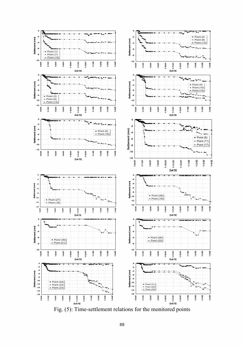
with the diaphragm wall installation and deep excavation for the basement. Results of the monitored settlement versus time, starting from installation of the diaphragm wall panels up to the excavation to the foundation level, are presented in Fig. (5). Table (4) shows the total settlement of different points due to diaphragm wall installation only (stage 1), and due to the complete site excavation (end to stage 4) along with the settlement increment between the two stages. The following sections discuss the observed settlement during the installation of the diaphragm wall and throughout the execution of the strutted deep excavation. 5.1 Settlement Due to Stage “1”-Diaphragm Wall Installation
The plotted records indicate that buildings’ subsidence increased for all points due to the trenching for the wall panels, which ended in mid of August 2001. A maximum settlement of 8.5 mm was recorded during trenching at the location of point 15 (Building “A” on pile foundations), while a null settlement was recorded at point 30 (Building “C” on pile foundations also). That could be related to the fact that point 15 is located very close to the diaphragm wall, while point 30 is located more than 40 m from the corner of the construction site. Points 20, 21, and 26 went through a minor upward movement of 0.6 mm between August 2, 2001 and August 6, 2001, while no activities on site was going during that period.
Figures 6 and 7 show plots of all settlement values with distances away from the wall. It can be seen that points of the same distance from the wall had diverse settlement values. That might be attributed to reasons related to the sequence of panel construction of the wall, the change in the subsurface soil conditions underneath each building, or due to each building stiffness and rigidity (El-Sayed and Abdel-Rahman, 2002). But, generally the average settlements of all buildings can be expressed with one envelope regardless of their foundation type. That envelope was recommended by (Abdel-Rahman and El-Sayed, 2002) to be with a maximum settlement equivalent to 0.045% of the diaphragm wall trench depth, while its extent away from the wall reaches to twice the same trench depth. Analysis of building settlement during the installation of the diaphragm wall of this project were reported and discussed in details by Abdel-Rahman and El-Sayed (2002). The proposed distribution of the settlement trough was expressed by the following equation:
6
max 22
−
=dxdSS trenchingtrenching ………….(1)
Where, “ trenchingS ” is the settlement at a distance “x” from the trench
boundary, “ trenchingSmax ” is the maximum settlement at the trench location, and “d” is the trench depth.
59

5.2 Settlement Due to Stages “2 to 4”-Excavation Inside the Pit During the excavation inside the pit, points (1) and (2) of building “A”,
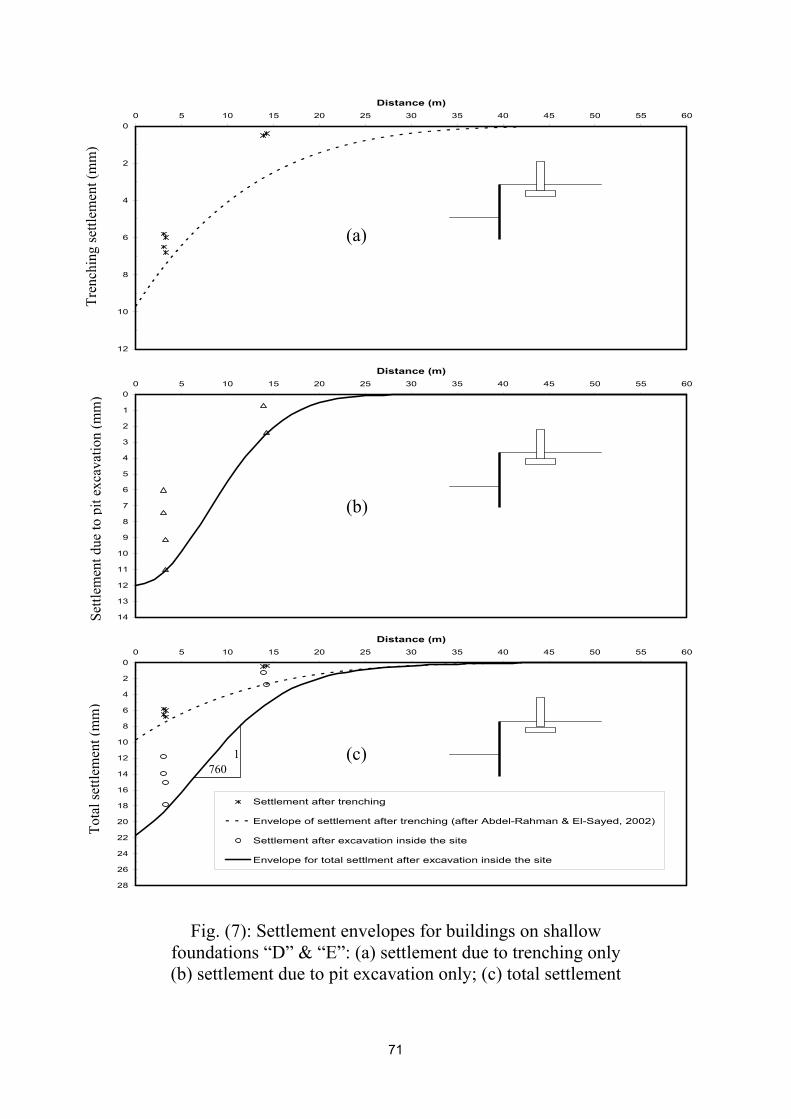
founded on pile foundation, experienced only insignificant values of heave (0.5 mm max.). Some other points did not have any change in their settlements, e.g. points (27), (28), (29), and (30) of buildings “B”, and “C” founded on pile foundations. However, buildings founded on shallow foundations suffered from high additional settlements due to the execution of stages 2 to 4 (maximum settlement increment of about 11.0 mm with an average increment at distance 3.2 m from the wall equal to 8.4 mm). Settlement of points on deep foundations showed much less settlement increments (max. 4.7 mm with an average increment at distance 2.5 m from the wall equal to 1.78 mm).
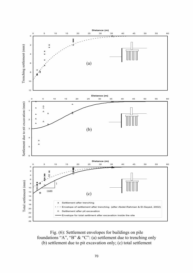
It is also worth noting that only points 18 and 19 of building “B” indicated the maximum settlement values monitored for buildings on deep foundation (4.7 mm), and generally didn’t follow the pattern of behavior of the rest of their similar 25 settlement points, as shown in Fig. (6-b). That is although building “B” is located a bit away from the excavation boundary than building “A”. This pattern could be related to the relatively short distance between the depth of its pile tip (14.0 m from ground surface, as reported or could be less when executed) and the maximum depth of excavation inside the pit (10.80 m). Therefore, points (18) and (19) located on building “B” were excluded in developing a settlement envelope for buildings on pile foundations due to deep excavation as shown in Figure (6-b). The settlement plots of buildings on pile foundation represents a case of deep excavation of depth less than the pile foundation depth.
Generally, the settlement of buildings on deep foundation, during executing stages 2 to 4, were much smaller than that occurred in stage 1 (diaphragm wall installation). On the contrary, buildings on shallow foundations generally underwent considerable settlements with higher rates. This is because the maximum depth of excavation was 11.5 m, which is much deeper than the shallow foundation depth but shallower than the pile foundation depths of buildings A, B, and C. In other words, the settlement gets generated with influencing values only when excavation occurs near to, or below the foundation level of buildings. That argument could be supported by the fact that building “B”, that is founded on pile foundation, showed a difference in behavior when the excavation occurred near to its foundation level (pile tip).
6. ANALYSIS OF OBSERVATIONS
Fig. (6) and Fig. (7) show the spatial distribution of the settlement field for building on deep foundations and on shallow foundations during the different stages of construction.
The settlement envelope can be mathematically described by adding an additional component (Spit excav) to the trenching settlement (Strenching); i.e.,
60
excavpittrnchingtotal SSS += ………….(2) The settlement component due to pit excavation only can be described by
the following equation:
⋅
−= 2
2
max )(2exp
HKxSS excavpitexcavpit ……….(3)
Where, “ excavpitS ” is the settlement at a distance “x” from the trench, “ excavpitSmax ” is the maximum settlement at the wall location, “K” is a dimensionless factor and “H” is the final depth of pit excavation. The anticipated distribution is similar to that proposed by Peck (1969a) to describe the settlements associated with shielded tunneling. Parameters of the previous equation were determined using best fitting analysis on the measured values. The results of curve fitting are summarized in Table (5).
Maximum settlements of 9.5 mm and 3.0 mm were extrapolated for the buildings on pile foundations due to wall installation and pit excavation, respectively. This indicates that most of the settlement occurred during the trenching stage (about 76%). The maximum settlements of buildings “D” and “E”, on shallow foundations, were 9.5 mm and 12 mm due to wall installation and pit excavation, respectively. On the contrary to pile-founded buildings, most of the settlement (about 56%) is attributed to pit excavation.
The settlement component due to pit excavation can be expressed as 0.03% H, and 0.11% H for the case of pile foundation and shallow foundation, respectively. However, the maximum total settlement is about 0.20% and 0.12% of the excavation depth for the cases of shallow, and pile foundations, respectively.
It can be seen from Figs (6-b and 7-b) that the widths of the settlement trough, in case of pit excavation, are about 41 m (3.8 H), and 24 m (2.2 H) for the cases of pile foundations and shallow foundations, respectively. However, in both cases, the final width of the settlement trough can be practically set to be 3.5 of the pit excavation depth (~38.0 m) as shown in Figs (6-c and 7-c).
The maximum angular inclinations of settlements are 1/1600 and 1/700 for deep foundations and shallow foundations, respectively. This points out that no structural distress would occur as verified by the dilapidation survey.
7. SUMMARY AND CONCLUSION
The effect of the foundation type and depth on the settlement fields of buildings surrounding deep excavations was studied based on analyses performed on the results acquired from a case history carried out in alluvial soils. The presented case history comprised inclusive settlement monitoring during the different stages of construction including diaphragm wall trenching and pit excavation. The compiled data demonstrates that wall construction stage triggered most of the settlement occurred for pile-founded buildings while
61
excavation stage produced most of the settlement for buildings on shallow foundations.
Based on the analysis performed on the data, the extent of the settlement troughs were found to reach up to a distance equivalent to 3.5 of the depth of excavation in alluvial soils. The maximum settlement at a boundary of strutted excavation was found to be in the range of 0.20% of the deep excavation depth. That settlement is generated only if the depth of deep excavations goes enough below the foundation depth of the proximate building. On the other hand, the maximum settlement due to diaphragm wall trenching was estimated to be equivalent to 0.045% of the diaphragm wall trench depth. The total settlement trough generated due to cut-and-cover excavations utilizing diaphragm walls will be the summation of both components; due to diaphragm wall trenching and due to strutted deep excavation.
8. REFERENCES
1. Abdel-Rahman, A. H. and El-Sayed, S. M., 2002, "Settlement Trough Associated with Diaphragm Wall Construction in Greater Cairo", the Journal of the Egyptian Geotechnical Society.
2. Ahmed, A. A. and Abd El-Salam, N., 1996, "In-situ Performance of Subway Stations in Cairo", Seventh International Colloquium on Structural and Geotechnical Engineering, Ain Shams University, Cairo, Egypt, Vol. 1, pp. 447-460
3. Attewell, P., Yeates, J. and Selby, A., 1986, "Soil Movements Induced by Tunnelling and Their Effects on Pipielines and Structures", Blackie & Sons Ltd., Glasgow.
4. Bentler, D. J., 1998, “Finite Element Analysis of Deep Excavations”, Ph.D. Thesis, Virginia Polytechnic Institute and State University, Blacksburg, Virginia.
5. Boone, S.J., 1997, "Ground-Movement-Related Building Damage", Journal of Geotechnical Engineering, ASCE, Vol. 122, No. 11, pp. 886-896.
6. Boscardin, M.D. and Cording, E.J., 1989, "Building Response to Excavation-induced Settlement", Journal of Geotechnical Engineering, ASCE, Vol. 115, No. 1, pp. 1-21.
7. Clough, G. and O'Rourke, T., 1990, "Construction Induced Movements of Insitu Walls", Design and Performance of Earth Retaining Structures, ASCE Geotechnical Special Publications 25, pp. 439-470.
8. Dunnicliff, J., 1988, "Geotechnical Instrumentation for Monitoring Field Performance", John Wiley and Sons, Inc., New York.
9. El-Nahhas, F.M., 1992, "Construction Monitoring of Urban Tunnels and Subway Stations", Tunneling and Underground Space Technology, Pergamon Press Ltd., Vol. 7, No. 4, pp. 425-439
10. El-Nahhas, F.M., Eisenstein, Z., and Shalaby, A., 1990, "In-situ Behaviour of Orabi Subway Stations during Construction", Proc. of first Alexandria
62
Conference on Structural and Geotechnical Engineering, Alexandria, Egypt, Vol. 1, pp. 189-198
11. El-Sayed, S. M. and Abdel-Rahman, A. H., 2002," Spatial Stress-Deformation Analysis for Installation of a Diaphragm Wall", the scientific bulletin of The Faculty of Engineering, Ain Shams University.
12. El-Sohby, M.A. and Mazen, O., 1985, “Geology aspects in Cairo Subsurface Development”, Proc. of the eleventh ICSMFE, San Francisco, Vol. 3, pp. 2401-2405.
13. Goldberg, D.T., Jaworski, W.E. and Gordon, M.D., 1976, "Lateral Support Systems and Underpinning", Report FHWA-RD-75-128, Vol. 1, Federal Highway Administration, Washington D.C., p. 312
14. Leca, E. and Clough, G., 1994, "Construction and Instrumentation of Underground Excavations", XIII ICSMFE, New Delhi, India, pp. 303-309
15. Murray, R. T., 1990, "Rapporteur's paper", Geotechnical Instrumentation in Practice, Proceedings of the conference of geotechnical instrumentation in civil engineering projects, Thomas Telford, London, England, pp. 75-85.
16. Ou, C.Y., Hsieh, P.G and Chiou, D.C., 1993, “Characteristics of Ground Surface Settlement during Excavation”, Canadian Geotechnical Journal, 30, pp. 758-767.
17. Peck, R. B., 1969a, State-of-the-art, "Deep Excavation and Tunneling in Soft Ground", Proceedings of the Seventh International Conference on Soil Mechanics and Foundation Engineering, Universidad Nacional Autonoma de Mexico Instituto de Ingenira, Mexico City, Mexico, Vol. 3, pp. 225-290
18. Peck, R.B, 1969b, "Advantages and Limitations of the Observational Method in Applied Soil Mechanics. Geotechnique, Vol. 19, No. 2, pp. 171-187.
19. Rushdi, S., 1989, "The Geology of Egypt", Balkema, Rotterdam. 20. Seok, J.W., 2001, “Settlement behavior of ground and structure adjacent to
excavation site”, Ph.D. thesis, School of Civil, Urban and Geosystem Engineering, Seoul National University, Seoul, Korea.
21. Skempton, A. W. and MacDonald, D. H., 1956, "The Allowable Settlements of Buildings", Proc., Inst. of Civil Engrs., Part III, The Institution of Civil Engrs., London, pp. 727-768.
22. Thasnanipan, N., Maung, A. W., Tanseng, P. and Teparaksa, W., 1999, “Behavior and Performance of Diaphragm Walls under Unbalanced Lateral Loading along the Chao Phraya River”, Field Measurements in Geomechanics, Leung, Tan & Phoon (eds), Balkema, Rotterdam, pp. 267-272
63
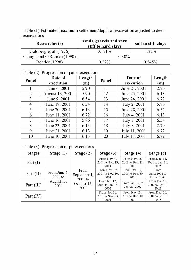
Table (1) Estimated maximum settlement/depth of excavation adjusted to deep excavations
Researcher(s) sands, gravels and very stiff to hard clays soft to stiff clays
Goldberg et al. (1976) 0.171% 1.22% Clough and O'Rourke (1990) 0.30%
Bentler (1998) 0.22% 0.545% Table (2): Progression of panel executions
Panel Date of execution
Length (m) Panel Date of
execution Length
(m) 1 June 6, 2001 5.90 11 June 24, 2001 2.70 2 August 13, 2001 5.90 12 June 25, 2001 6.13 3 June 9, 2001 6.54 13 June 26, 2001 6.72 4 June 18, 2001 6.54 14 July 2, 2001 5.86 5 June 20, 2001 6.13 15 June 28, 2001 6.54 6 June 11, 2001 6.72 16 July 4, 2001 6.13 7 June 16, 2001 5.86 17 July 7, 2001 6.54 8 June 23, 2001 6.13 18 July 8, 2001 2.70 9 June 21, 2001 6.13 19 July 11, 2001 6.72
10 June 10, 2001 6.13 20 July 10, 2001 6.72 Table (3): Progression of pit executions
Stages Stage (1) Stage (2) Stage (3) Stage (4) Stage (5)
Part (I) From Nov. 4,
2001 to Nov. 13, 2001
From Nov. 18, 2001 to Dec. 11,
2001
From Dec. 11, 2001 to Jan. 10,
2002
Part (II) From Nov. 19,
2001 to Dec. 10, 2001
From Dec. 12, 2001 to Dec. 30,
2001
From Jan.2,2002 to Jan. 9, 2002
Part (III) From Jan. 12,
2002 to Jan. 18, 2002
From Jan. 19, to Jan. 20, 2002
From Jan. 21, 2002 to Feb. 3,
2002
Part (IV)
From June 6, 2001 to
August 13, 2001
From September 1,
2001 to October 15,
2001 From Nov.20,
2001 to Nov. 23, 2001
From Nov. 24, 2001 to Dec. 10,
2001
From Dec. 20, 2001 to Feb. 1,
2002
64
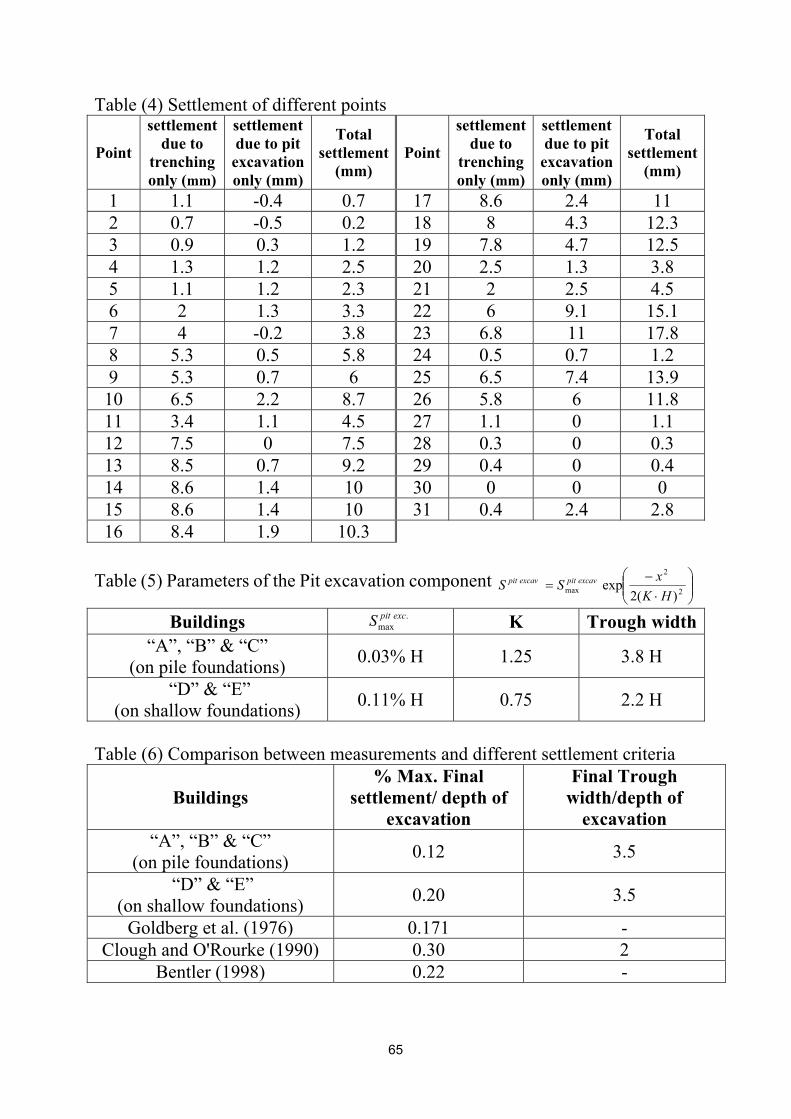
Table (4) Settlement of different points
Point
settlement due to
trenching only (mm)
settlement due to pit excavation only (mm)
Total settlement
(mm) Point
settlement due to
trenching only (mm)
settlement due to pit excavation only (mm)
Total settlement
(mm)
1 1.1 -0.4 0.7 17 8.6 2.4 11 2 0.7 -0.5 0.2 18 8 4.3 12.3 3 0.9 0.3 1.2 19 7.8 4.7 12.5 4 1.3 1.2 2.5 20 2.5 1.3 3.8 5 1.1 1.2 2.3 21 2 2.5 4.5 6 2 1.3 3.3 22 6 9.1 15.1 7 4 -0.2 3.8 23 6.8 11 17.8 8 5.3 0.5 5.8 24 0.5 0.7 1.2 9 5.3 0.7 6 25 6.5 7.4 13.9 10 6.5 2.2 8.7 26 5.8 6 11.8 11 3.4 1.1 4.5 27 1.1 0 1.1 12 7.5 0 7.5 28 0.3 0 0.3 13 8.5 0.7 9.2 29 0.4 0 0.4 14 8.6 1.4 10 30 0 0 0 15 8.6 1.4 10 31 0.4 2.4 2.8 16 8.4 1.9 10.3
Table (5) Parameters of the Pit excavation component
⋅
−= 2
2
max )(2exp
HKxSS excavpitexcavpit
Buildings .max
excpitS K Trough width “A”, “B” & “C”
(on pile foundations) 0.03% H 1.25 3.8 H
“D” & “E” (on shallow foundations) 0.11% H 0.75 2.2 H
Table (6) Comparison between measurements and different settlement criteria
Buildings % Max. Final
settlement/ depth of excavation
Final Trough width/depth of
excavation “A”, “B” & “C”
(on pile foundations) 0.12 3.5
“D” & “E” (on shallow foundations) 0.20 3.5
Goldberg et al. (1976) 0.171 - Clough and O'Rourke (1990) 0.30 2
Bentler (1998) 0.22 -
65
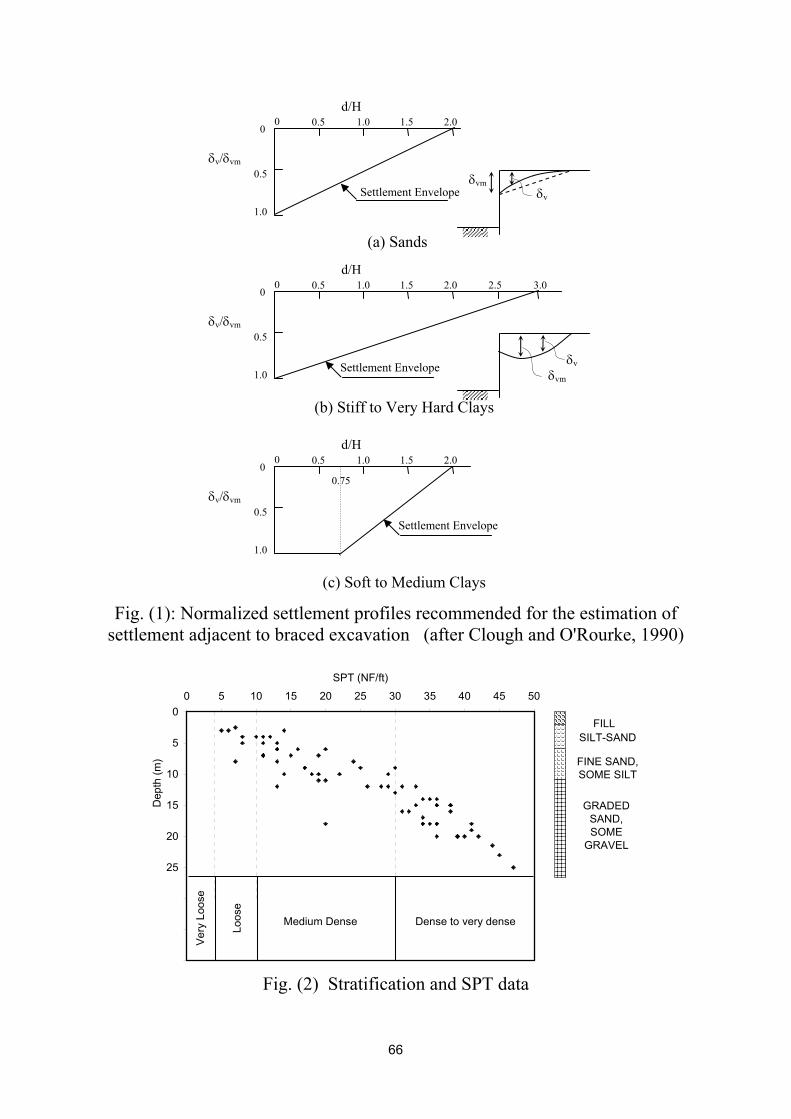
Fig. (1): Normalized settlement profiles recommended for the estimation of
settlement adjacent to braced excavation (after Clough and O'Rourke, 1990)
0
5
10
15
20
25
30
35
40
0 5 10 15 20 25 30 35 40 45 50
SPT (NF/ft)
Dep
th (m
)
FILLSILT-SAND
FINE SAND, SOME SILT
GRADED SAND, SOME
GRAVEL
Ver
y Lo
ose
Loos
e
Medium Dense Dense to very dense
Fig. (2) Stratification and SPT data
0
0.5
1.0
0.5 0 1.0 1.5 2.0
δv/δvm
d/H
Settlement Envelope δvm
δv
(a) Sands
0
0.5
1.0
0.5 0 1.0 1.5 2.0
δv/δvm
d/H
Settlement Envelope δvm
δv
(b) Stiff to Very Hard Clays
2.5 3.0
0
0.5
1.0
0.5 0 1.0 1.5 2.0
δv/δvm
d/H
Settlement Envelope
(c) Soft to Medium Clays
0.75
66
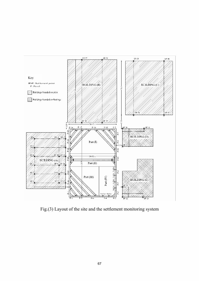
Fig.(3) Layout of the site and the settlement monitoring system
Key
67
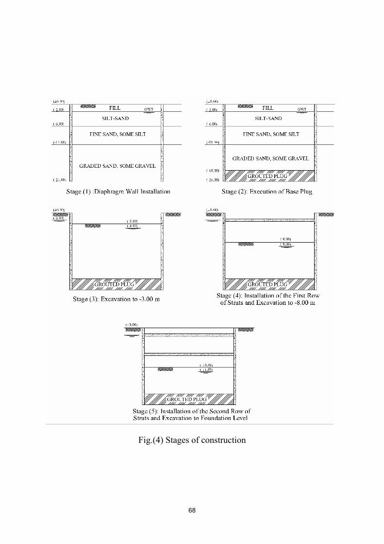
Fig.(4) Stages of construction
68
-10
-8
-6
-4
-2
0
1-6-
01
1-7-
01
1-8-
01
1-9-
01
1-10
-01
1-11
-01
1-12
-01
1-1-
02
1-2-
02
1-3-
02
1-4-
02
DATE
Settl
emen
t (m
m)
Point (1)Point (7)Point (12)
-10
-8
-6
-4
-2
0
1-6-
01
1-7-
01
1-8-
01
1-9-
01
1-10
-01
1-11
-01
1-12
-01
1-1-
02
1-2-
02
1-3-
02
1-4-
02
DATE
Settl
emen
t (m
m)
Point (2)Point (8)Point (13)
-12
-10
-8
-6
-4
-2
0
1-6-
01
1-7-
01
1-8-
01
1-9-
01
1-10
-01
1-11
-01
1-12
-01
1-1-
02
1-2-
02
1-3-
02
1-4-
02DATE
Settl
emen
t (m
m)
Point (3)Point (9)Point (14)
-12
-10
-8
-6
-4
-2
0
1-6-
01
1-7-
01
1-8-
01
1-9-
01
1-10
-01
1-11
-01
1-12
-01
1-1-
02
1-2-
02
1-3-
02
1-4-
02
DATE
Settl
emen
t (m
m)
Point (4)Point (10)Point (15)
-12
-10
-8
-6
-4
-2
0
1-6-
01
1-7-
01
1-8-
01
1-9-
01
1-10
-01
1-11
-01
1-12
-01
1-1-
02
1-2-
02
1-3-
02
1-4-
02
DATE
Settl
emen
t (m
m)
Point (5)Point (16)
-12
-10
-8
-6
-4
-2
0
1-6-
01
1-7-
01
1-8-
01
1-9-
01
1-10
-01
1-11
-01
1-12
-01
1-1-
02
1-2-
02
1-3-
02
1-4-
02
DATE
Settl
emen
t (m
m)
Point (6)Point (11)Point (17)
-14
-12
-10
-8
-6
-4
-2
0
1-6-
01
1-7-
01
1-8-
01
1-9-
01
1-10
-01
1-11
-01
1-12
-01
1-1-
02
1-2-
02
1-3-
02
1-4-
02
DATE
Settl
emen
t (m
m)
Point (27)Point (18)
-12.5
-14
-12
-10
-8
-6
-4
-2
0
1-6-
01
1-7-
01
1-8-
01
1-9-
01
1-10
-01
1-11
-01
1-12
-01
1-1-
02
1-2-
02
1-3-
02
1-4-
02
DATE
Settl
emen
t (m
m)
Point (28)Point (19)
-10
-8
-6
-4
-2
0
1-6-
01
1-7-
01
1-8-
01
1-9-
01
1-10
-01
1-11
-01
1-12
-01
1-1-
02
1-2-
02
1-3-
02
1-4-
02
DATE
Settl
emen
t (m
m)
Point (30)Point (21)
-10
-8
-6
-4
-2
0
1-6-
01
1-7-
01
1-8-
01
1-9-
01
1-10
-01
1-11
-01
1-12
-01
1-1-
02
1-2-
02
1-3-
02
1-4-
02
DATE
Settl
emen
t (m
m)
Point (29)Point (20)
-18
-16
-14
-12
-10
-8
-6
-4
-2
0
1-6-
01
1-7-
01
1-8-
01
1-9-
01
1-10
-01
1-11
-01
1-12
-01
1-1-
02
1-2-
02
1-3-
02
1-4-
02
DATE
Settl
emen
t (m
m)
Point (24)Point (22)Point (23)
-16
-14
-12
-10
-8
-6
-4
-2
0
1-6-
01
1-7-
01
1-8-
01
1-9-
01
1-10
-01
1-11
-01
1-12
-01
1-1-
02
1-2-
02
1-3-
02
1-4-
02
DATE
Settl
emen
t (m
m)
Point (31)Point (26)Point (25)
Fig. (5): Time-settlement relations for the monitored points
69
0
2
4
6
8
10
12
0 5 10 15 20 25 30 35 40 45 50 55 60
Distance (m)
Tren
chin
g se
ttlem
ent (
mm
)
0
1
2
3
4
5
6
0 5 10 15 20 25 30 35 40 45 50 55 60
Distance (m)
Settl
emen
t due
to p
it ex
cava
tion
(mm
)
0
2
4
6
8
10
12
14
16
18
20
22
24
26
0 5 10 15 20 25 30 35 40 45 50 55 60
Distance (m)
Tota
l set
tlem
ent (
mm
)
Settlement after trenching
Envelope of settlement after trenching (after Abdel-Rahman & El-Sayed, 2002)
Settlement after pit excavation
Envelope for total settlment after excavation inside the site
Fig. (6): Settlement envelopes for buildings on pile foundations “A”, “B” & “C”: (a) settlement due to trenching only
(b) settlement due to pit excavation only; (c) total settlement
(a)
(b)
(c) 1600
1
Tren
chin
g se
ttlem
ent (
mm
) Se
ttlem
ent d
ue to
pit
exca
vatio
n (m
m)
Tota
l set
tlem
ent (
mm
)
70
0
2
4
6
8
10
12
0 5 10 15 20 25 30 35 40 45 50 55 60
Distance (m)Tr
ench
ing
settl
emen
t (m
m)
0
1
2
3
4
5
6
7
8
9
10
11
12
13
14
0 5 10 15 20 25 30 35 40 45 50 55 60
Distance (m)
Settl
emen
t due
to p
it ex
cava
tion
(mm
)
0
2
4
6
8
10
12
14
16
18
20
22
24
26
28
0 5 10 15 20 25 30 35 40 45 50 55 60
Distance (m)
Tota
l Set
tlem
ent (
mm
)
Settlement after trenching
Envelope of settlement after trenching (after Abdel-Rahman & El-Sayed, 2002)
Settlement after excavation inside the site
Envelope for total settlment after excavation inside the site
Fig. (7): Settlement envelopes for buildings on shallow foundations “D” & “E”: (a) settlement due to trenching only (b) settlement due to pit excavation only; (c) total settlement
(a)
(b)
(c) 760
1
Tren
chin
g se
ttlem
ent (
mm
) Se
ttlem
ent d
ue to
pit
exca
vatio
n (m
m)
Tota
l set
tlem
ent (
mm
)
71