How We Are Using New Technology at an Old Excavation: The Seyitomer Mound Salvage Excavation Project
16
1 How We Are Using New Technology at an Old Excavation: The Seyitomer Mound Salvage Excavation Project Elif GENÇ Dumlupınar University, Kütahya, Turkey Seyitömer Höyük is located in the Seyitömer Lignite Company’s reserve zone in Kütahya. It is an ancient habitation site measuring 150×150 meters. Its summit is situated 23.5 meters above the surroundings. The site must be excavated completely by 2010 because the Seyitömer Lignite Company intends to mine 12 million tons of an exploitable coal reserve underneath it. This is the third time this site has been the subject of a research project. The Eskişehir Museum in 1989 for one season and the Afyon Museum, from 1990 to 1995, worked at Seyitömer Höyük. Both excavations together managed to clear only about 1/10 th of the mound. As a result of those archeological projects, the archaeologists learned that the mound was inhabited during the Chalcolithic, Bronze, Iron, Hellenistic and Roman periods, beginning about 5000 years ago. The previous excavations used traditional excavation and documentation methods. Our task is to incorporate the old data and use it to help us understand the site and its remains. The challenge to the archaeologist is unique, presenting problems and solutions both in completing the task using the best archaeological methods available and to do it as a salvage excavation. This paper will explain what we have done to bring Seyitomer into the 21 st century. Introduction Seyitömer Höyük is located 26 kilometers north of Kütahya, Turkey (Fig. 1), and within the area operated by the Seyitömer Lignite Company (Fig. 2). It is an ancient habitation site of 150×150 m meters with its summit at a height of 23.5 meters above the surroundings. Its name derives from the village of Seyitömer which used to border it (Fig. 3). Fig.1 - Turkey, Kütahya and Seyitömer Village maps. How We Are Using New KÜT KÜTAHYA
Transcript of How We Are Using New Technology at an Old Excavation: The Seyitomer Mound Salvage Excavation Project
1
How We Are Using New Technology at an Old Excavation:
The Seyitomer Mound Salvage Excavation Project
Elif GENÇ
Dumlupınar University, Kütahya, Turkey
Seyitömer Höyük is located in the Seyitömer Lignite Company’s reserve zone in Kütahya. It is an ancient
habitation site measuring 150×150 meters. Its summit is situated 23.5 meters above the surroundings. The
site must be excavated completely by 2010 because the Seyitömer Lignite Company intends to mine 12
million tons of an exploitable coal reserve underneath it. This is the third time this site has been the subject
of a research project. The Eskişehir Museum in 1989 for one season and the Afyon Museum, from 1990 to
1995, worked at Seyitömer Höyük. Both excavations together managed to clear only about 1/10th of the
mound. As a result of those archeological projects, the archaeologists learned that the mound was inhabited
during the Chalcolithic, Bronze, Iron, Hellenistic and Roman periods, beginning about 5000 years ago. The
previous excavations used traditional excavation and documentation methods. Our task is to incorporate the
old data and use it to help us understand the site and its remains. The challenge to the archaeologist is
unique, presenting problems and solutions both in completing the task using the best archaeological
methods available and to do it as a salvage excavation. This paper will explain what we have done to bring
Seyitomer into the 21st century.
Introduction
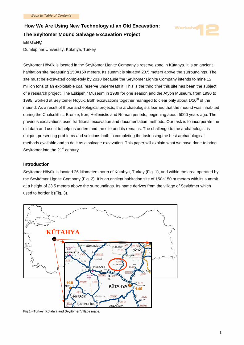
Seyitömer Höyük is located 26 kilometers north of Kütahya, Turkey (Fig. 1), and within the area operated by
the Seyitömer Lignite Company (Fig. 2). It is an ancient habitation site of 150×150 m meters with its summit
at a height of 23.5 meters above the surroundings. Its name derives from the village of Seyitömer which
used to border it (Fig. 3).
Fig.1 - Turkey, Kütahya and Seyitömer Village maps.
How We Are Using New
KÜTKÜTAHYA
lanm07uhl
Stempel

2
Fig.2 - The Seyitömer Lignite Company Area
Fig.3 -The Seyitömer Mound, 2006-2007
Place of the Old Seyitömer Village
The Seyitömer Mound, 2006-2007

3
Earlier excavations, initiated by the Eskişehir Museum Directorate in 1989 1, were continued by the Afyon
Museum Directorate from 1990-1995 2. During these excavations only about 1/10th of the mound was
excavated (Figs. 4-9). As a result of the archeological excavations, it was discovered that the mound was
inhabited mainly during the Chalcolithic, Bronze, Iron, Hellenistic and Roman periods, beginning about 5000
years ago.
Fig.4 - Seyitömer Mound, Previous Excavations, 1990
Fig.5 - Seyitömer Mound, Previous Excavations, 1991
In 2005, the Seyitömer Lignite Company Administration applied to the Ministry of Culture and Tourism with
an aim to reinitiate the excavation so that the coal reserve present underneath the mound could be exploited.
For this reason, the Dumlupınar University Rectorate established its Department of Archeology, and then
signed a protocol with the Turkish Coal Board to provide the required specialists to re-open the excavation 3.
Consequently, in 2006, the present salvage excavations at the Seyitömer mound began under the direction
of Professor A. Nejat Bilgen, the head of the Department of Archaeology, at Dumlupınar University 4 (Fig.10).
The site must be excavated completely by 2010 because the Seyitömer Lignite Company intends to mine the
12 million tons of exploitable coal reserve underneath it. Because the site is going to be completely
destroyed, we have a unique situation here. Our excavation and documentation methods must be as
comprehensive as possible in order to arrive at good results that will assist us in learning about the
archaeology of the site and its surroundings over time. The use of new digital technology brings us closer to

4
this realization. This paper will explain what methods we have adopted both to incorporate the old
excavations data in our thinking and add our own, using modern technology.
Fig. 6 - Stair Way, Late Phrygian Period, 1993
The Previous Excavations: What did they do?
The previous excavators used a traditional paper-based documentation system. These were:
a- Documentation forms for the small finds:
-The Daily Field Forms,
-The Objects Forms,
-The Statistics Forms,
b- Photography with black and white film
c- Drawings by hand of the all plans and finds.
a- Documentation forms for the small finds: The Daily Field Forms included the square number, the depth of
the level, period of the finds and a count of the materials. There were also written reports and daily sketch
plans. The Objects Forms had a complete description of the small finds, including place identification, type
5
and size. For all sherds of the same period and at the same depth, there was one statistics form filled out for
each square: numbers of rims, bases, body sherds, handles and kinds of decoration.
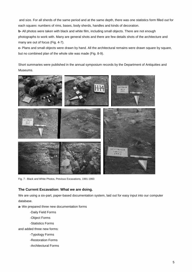
b- All photos were taken with black and white film, including small objects. There are not enough
photographs to work with. Many are general shots and there are few details shots of the architecture and
many are out of focus (Fig. 4-7).
c- Plans and small objects were drawn by hand. All the architectural remains were drawn square by square,
but no combined plan of the whole site was made (Fig. 8-9).
Short summaries were published in the annual symposium records by the Department of Antiquities and
Museums.
Fig. 7 - Black and White Photos, Previous Excavations, 1991-1993
The Current Excavation: What we are doing.
We are using a six-part, paper-based documentation system, laid out for easy input into our computer
database.
a- We prepared three new documentation forms
-Daily Field Forms
-Object Forms
-Statistics Forms
and added three new forms:
-Typology Forms
-Restoration Forms
-Architectural Forms

6
Fig. 8 - Plan, Previous Excavations
Fig. 9 - Plan and Small Finds, Previous Excavations
b- All photography is now digital and in color, using several different digital cameras that are hand-held. One
of them is a Nikon that is more often mounted on a tripod for images that might be published. There is also a
Rollie Matrix camera—more on that in a moment. We can also document with a camcorder,
c- There is a computer database
d- We are using the Harris Matrix Method in some newly excavated areas.
e- All architecture, both top plans and wall profiles, is first photographed with meter tapes and then drawn on
the computer with AutoCAD programs. Elevations are taken using a total station.

7
f- We are preparing massing models for some of the architecture, and are preparing 3D and VR
presentations.
Fig. 10 - Seyitömer Mound, Current Excavation, 2007
A few remarks to explain our documentation system further:
a- The New Documentation Forms are now used for all the small finds and the architecture. The
archaeologists supervising the work in each square use the new Daily Field Forms as they work in the field.
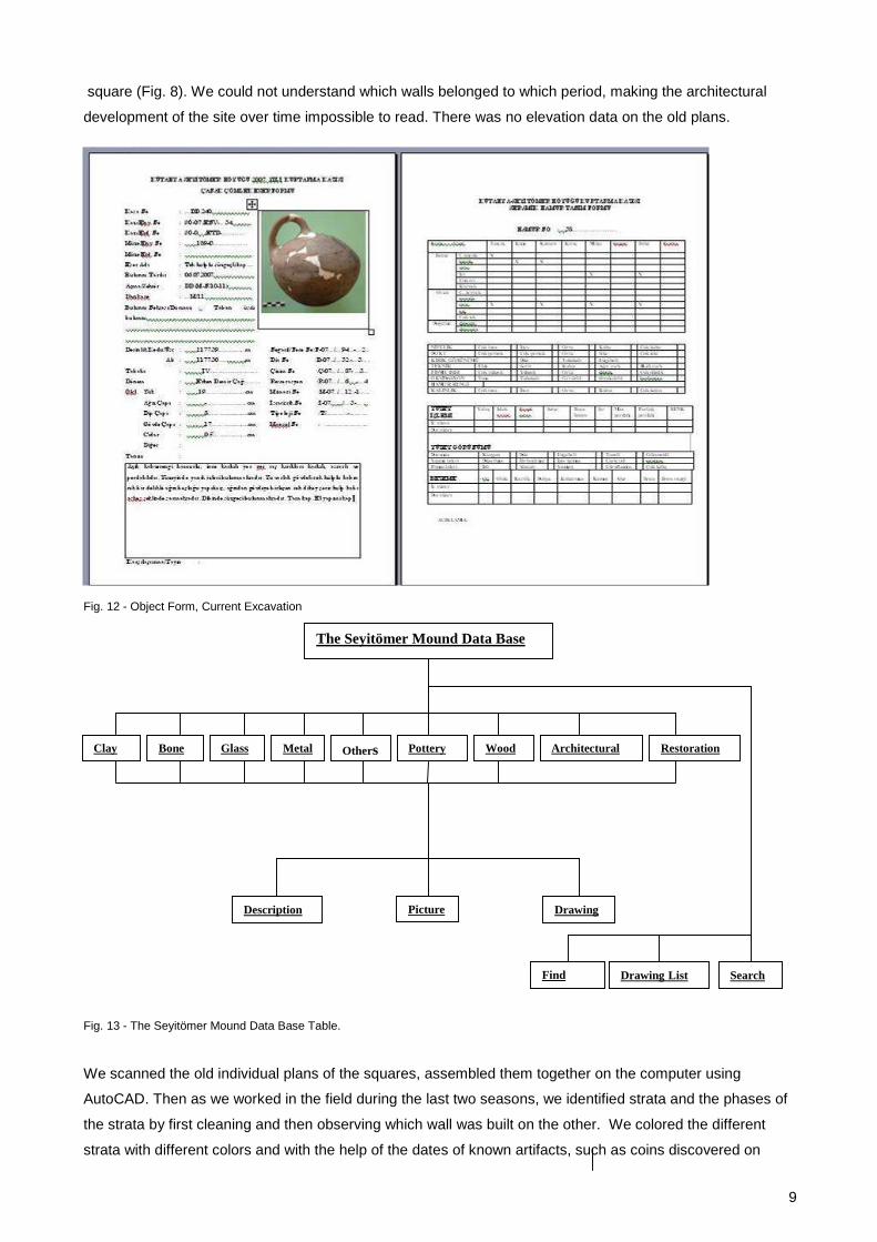
These forms document the daily excavation results (Fig. 11). Object Forms record every detail about the
small finds as they come out of the ground (Fig. 12). The Statistics Forms, created for the pottery fragments,
are filled out in the laboratory when a unit in the excavation is finished. Then the Typology Forms are
integrated with the statistics forms when we learn what kind of types we have. The Restoration Forms are
used for all the pottery that goes to the restoration laboratory. This way we can study pottery both before
restoration and after restoration. Architectural Forms are used for the documentation of all the details of the
architectural remains. All this information is then inputed into our digital data base.
b- As explained above, all photography is digital and in color. We tried a Matrix camera for the architectural
drawings. But we did not like the results. Now we use hand- held cameras sometimes on a tripod, with
measuring rulers in the view and then draw on the computer using AutoCAD. We can draw all the tops and
profiles of the walls accurately and easily using this method. Because this project is a salvage excavation
and we are working against time to remove all the architecture quickly after we document, we have not tried
to improve our use of the Matrix camera.
c- We are entering into the data base all of the information on our hand-written forms. We have categories
for all materials (Fig. 13). The data-base program was constructed to include every conceivable category for

8
description, pictures and drawings of the architecture, and notes about the context of the finds and
restoration reports, where appropriate (Figs. 14-16). There is also a find list and an illustration list attached to
a search engine so that information can be found in various ways (Figs. 17-18). The data base could be
posted on a web page, but no decision about doing this has been made.
d- Harris Matrix Method: Since we spend a good proportion of the last two six-month seasons cleaning and
clearing the debris of the old excavation and trying to understand the site, we have not had much chance to
excavate untouched soil. But we are now using the Harris Matrix Method in the field as an approach both to
understand the old stratigraphy, and to help us understand the newly excavated areas. This method has
helped us distinguish the physical remains of several strata in the old excavation, and the result is that we
can now see the plans of the settlement on the site over time. New digital maps of each stratum are in the
process of being created as I will explain in a moment. The old excavation’s maps and plans did not explain
the relationship between building and building, layer and layer: this was only described in general terms in
the excavation reports with limited illustration. In new areas, the application of the method is helping us learn
the complex relationship among the walls and floors and units of material culture, what some archaeologists
term features and loci. These relationships are now graphed and are part of our documentation on our digital
database and will lead to an improved understanding of the stratigraphy of the site over time (Figs. 19-20).
Fig. 11 - Daily Field Form, Current Excavation
e- In the previous excavations, the architectural remains of each square were drawn separately but no
overall plan of the site was created from these drawings. Also the stratigraphic relationship among the
various buildings excavated and drawn on the individual plans of the squares was not clear. The previous
excavators drew all the architecture of the different periods together on the same plan in each individual
9
square (Fig. 8). We could not understand which walls belonged to which period, making the architectural
development of the site over time impossible to read. There was no elevation data on the old plans.
Fig. 12 - Object Form, Current Excavation
Fig. 13 - The Seyitömer Mound Data Base Table.
We scanned the old individual plans of the squares, assembled them together on the computer using
AutoCAD. Then as we worked in the field during the last two seasons, we identified strata and the phases of
the strata by first cleaning and then observing which wall was built on the other. We colored the different
strata with different colors and with the help of the dates of known artifacts, such as coins discovered on
The Seyitömer Mound Data Base
Wood Glass Pottery Bone Metal Clay Others Architectural Restoration
Find List
Drawing List Search
Description Picture Drawing

10
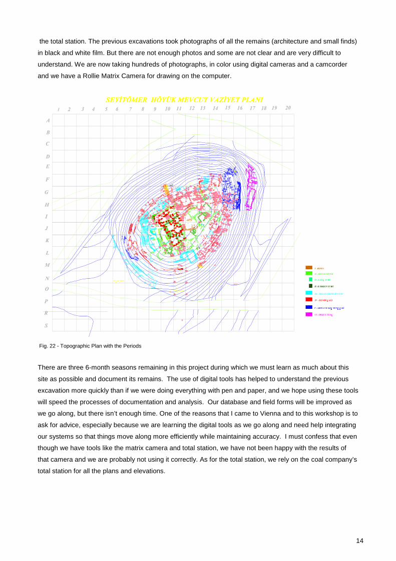
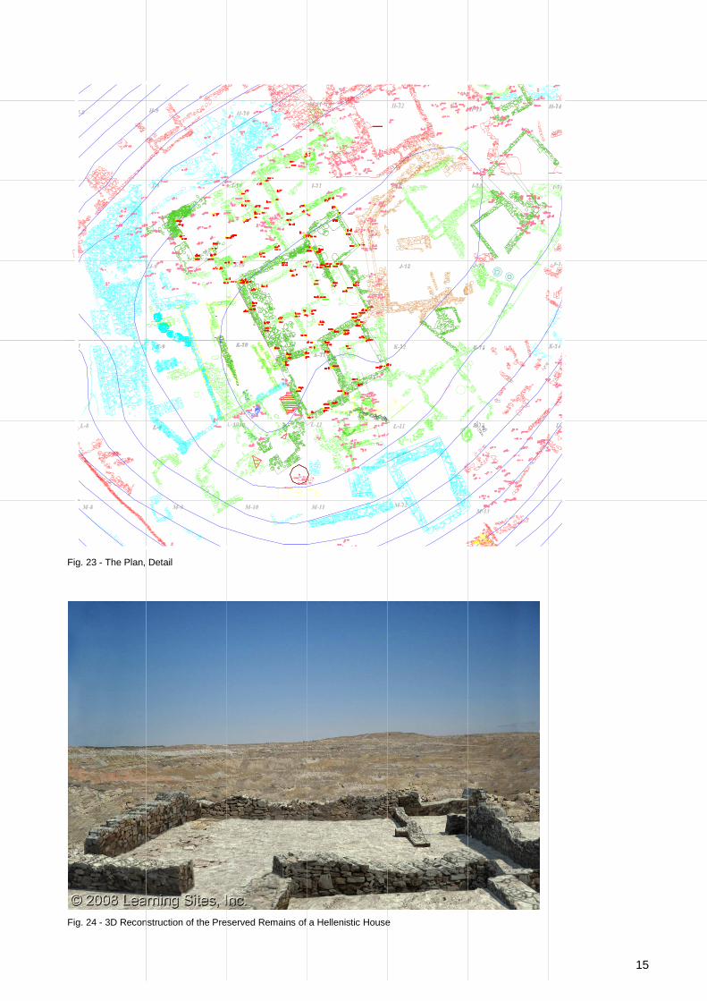
floors, and have begun to assign them to archaeological and historical periods. A single plan now exists
which explains the different strata as we understand them (Figs. 21-23).
The topographic plan was also not current nor sufficient for our purposes. There were two versions, 1989
and 1990—the latter is the more complete—published in the annual reports of the symposium. We re-drew
the topographic plan of the mound and superimposed our assembled plan on it (Fig. 22).
Fig. 14 - Data Base, First Pages
Fig. 15 - Data Base, Small Finds Page
Fig. 16 - Data Base, Small Finds Page

11
Fig. 17 - Data Base, Find List and the Drawing List Pages
Fig. 18 - Data Base, Search Page
Now all new architecture is drawn on the computer with an AutoCAD program, version 2004, and we are
using a total station for elevations. We checked our data with the old top plans using the total station and
found a few but important places that had to be corrected. Usually it was the direction of a wall. We studied
the architecture that survived carefully and re-established the boundaries of the old square units in the field
and on the plan. Now the site plan is correct. Unfortunately some of the buildings excavated by the previous
teams have not survived, either because they were removed to make way for further excavations, or they
collapsed in the dozen years between our project and theirs.

12
Fig. 19 - Harris Matrix Method
Fig. 20 - Harris Matrix Method, an example of a graph
f- 3 Dimensional digital reconstructions and VR: Since this is an excavation that will try to excavate the whole
site and since the Coal Company will destroy the site when our project is over, it was suggested that it might
be a good idea to document the site in such a way that it could be reconstructed digitally and in 3D. In the
best of times, this is an expensive undertaking. But with the help of the Joukowsky Family Foundation and
L1 (topsoil)
L2 (subsoil)
L7 (small/medium rock tumble)
South Third
L11 (compact dirt)
L17 (rock circle)
L12 (possible pavement)
L16 (rock circle dirt)
L18 (small rock wall)
L19 (small rock tumble)
L20 (reddish brown dirt)

13
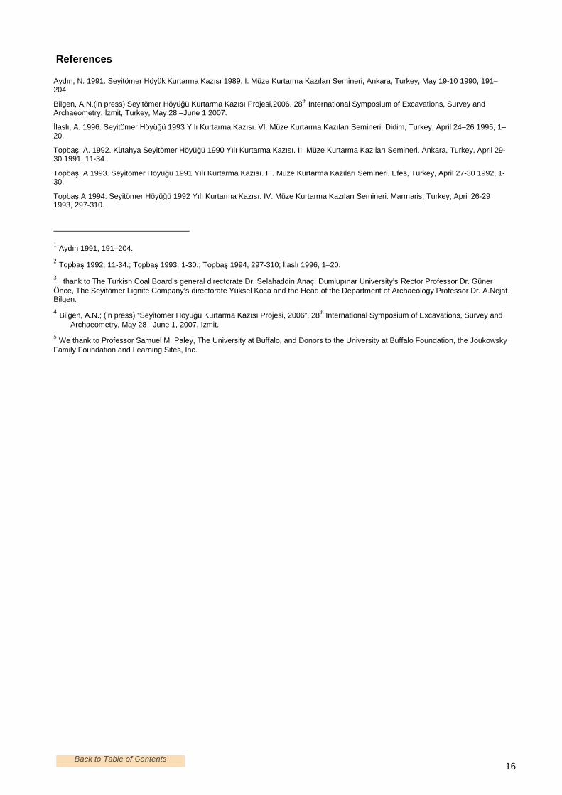
other donors from the United States and the University of Buffalo 5, characteristic buildings of each stratum
are being photographed intensively in order to create a VR reconstruction of as much of the excavated
remains of the Höyük as possible. The VR is being done by Learning Sites in-corporated. When we add the
artifacts from the excavation itself to the architecture, the VR will stand as an example of what was found
and each model and the interactive program can be studied on its own merits (Figs. 24).
Fig. 21 - Plan of the Periods represented on the Mound
Conclusion
The old documentation system was not sufficient for our purposes. We created a new one, and now use a
computerized data base for all finds and architectural remains. The previous projects drew the architectural
remains of each square separately. There was no combined plan of the whole site. We scanned the
individual plans of the architectural remains of each separate square on the computer, attached them
together and created a single plan. They drew all the strata with same color. We checked the stratigraphy on
site and colored the different strata with different colors. We can now see the different periods on the same
map. Using the total station and AutoCAD programs, we corrected the old plans, and now can continue to
document our work in relationship to theirs. The topographic plan was not current and not sufficient for our
purposes. We re-drew the topographic plan of the mound again. The corners of the squares (excavation
units) did not survive from the time of the earlier excavations. We re-pointed the corners of the squares using
The Current Excavations
14
the total station. The previous excavations took photographs of all the remains (architecture and small finds)
in black and white film. But there are not enough photos and some are not clear and are very difficult to
understand. We are now taking hundreds of photographs, in color using digital cameras and a camcorder
and we have a Rollie Matrix Camera for drawing on the computer.
Fig. 22 - Topographic Plan with the Periods
There are three 6-month seasons remaining in this project during which we must learn as much about this
site as possible and document its remains. The use of digital tools has helped to understand the previous
excavation more quickly than if we were doing everything with pen and paper, and we hope using these tools
will speed the processes of documentation and analysis. Our database and field forms will be improved as
we go along, but there isn’t enough time. One of the reasons that I came to Vienna and to this workshop is to
ask for advice, especially because we are learning the digital tools as we go along and need help integrating
our systems so that things move along more efficiently while maintaining accuracy. I must confess that even
though we have tools like the matrix camera and total station, we have not been happy with the results of
that camera and we are probably not using it correctly. As for the total station, we rely on the coal company’s
total station for all the plans and elevations.
15
Fig. 23 - The Plan, Detail
Fig. 24 - 3D Reconstruction of the Preserved Remains of a Hellenistic House
16
References
Aydın, N. 1991. Seyitömer Höyük Kurtarma Kazısı 1989. I. Müze Kurtarma Kazıları Semineri, Ankara, Turkey, May 19-10 1990, 191–204.
Bilgen, A.N.(in press) Seyitömer Höyüğü Kurtarma Kazısı Projesi,2006. 28th International Symposium of Excavations, Survey and Archaeometry. Đzmit, Turkey, May 28 –June 1 2007.
Đlaslı, A. 1996. Seyitömer Höyüğü 1993 Yılı Kurtarma Kazısı. VI. Müze Kurtarma Kazıları Semineri. Didim, Turkey, April 24–26 1995, 1–20.
Topbaş, A. 1992. Kütahya Seyitömer Höyüğü 1990 Yılı Kurtarma Kazısı. II. Müze Kurtarma Kazıları Semineri. Ankara, Turkey, April 29-30 1991, 11-34.
Topbaş, A 1993. Seyitömer Höyüğü 1991 Yılı Kurtarma Kazısı. III. Müze Kurtarma Kazıları Semineri. Efes, Turkey, April 27-30 1992, 1-30.
Topbaş,A 1994. Seyitömer Höyüğü 1992 Yılı Kurtarma Kazısı. IV. Müze Kurtarma Kazıları Semineri. Marmaris, Turkey, April 26-29 1993, 297-310.
1 Aydın 1991, 191–204.
2 Topbaş 1992, 11-34.; Topbaş 1993, 1-30.; Topbaş 1994, 297-310; Đlaslı 1996, 1–20.
3 I thank to The Turkish Coal Board’s general directorate Dr. Selahaddin Anaç, Dumlupınar University’s Rector Professor Dr. Güner Önce, The Seyitömer Lignite Company’s directorate Yüksel Koca and the Head of the Department of Archaeology Professor Dr. A.Nejat Bilgen.
4 Bilgen, A.N.; (in press) “Seyitömer Höyüğü Kurtarma Kazısı Projesi, 2006”, 28th International Symposium of Excavations, Survey and Archaeometry, May 28 –June 1, 2007, Izmit.
5 We thank to Professor Samuel M. Paley, The University at Buffalo, and Donors to the University at Buffalo Foundation, the Joukowsky Family Foundation and Learning Sites, Inc.
lanm07uhl
Stempel