Detection of Individual Specimens in Populations Using Contour Energies

Boundary Delineation in Prostate Imaging using
Active Contour Segmentation Method with
Interactively Defined Object Regions
Yan Zhang1⋆, Bogdan J. Matuszewski1, Aymeric Histace2,Frederic Precioso2, Judith Kilgalon3, and Christopher Moore3
1 Applied Digital Signal and Image Processing Research Centre,School of Computing Engineering and Physical Sciences,
University of Central Lancashire, Preston PR1 2HE, United Kingdom2 ETIS Lab, CNRS/ENSEA/Univ Cergy-Pontoise, 6, av. du Ponceau,
95014 Cergy-Pontoise, France3 North Western Medical Physics, The Christie NHS Foundation Trust,
Manchester, M20 4BX, United Kingdom
Abstract. Active contour methods are often methods of choice for de-manding segmentation problems, yet segmentation of medical imageswith complex intensity patterns still remains a challenge for these meth-ods. This paper proposes a method to incorporate interactively spec-ified foreground/background regions into the active model frameworkwhile keeping the user interaction to the minimum. To achieve that,the proposed functional to be minimized includes a term to encourageactive contour to separate the points close to the specified foregroundregion from the points close to the specified background region in termsof geodesic distance. The experiments on multi-modal prostate imagesdemonstrate that the proposed method not only can achieve robust andaccurate results, but also provides an efficient way to interactively im-prove the results.
Keywords: Image segmentation, prostate imaging, MRI, CT, TRUS,active contour, fast marching
1 Introduction
Originally proposed in [1], active contour models for image segmentation haveattracted extensive research in the past two decades. The basic idea of the activecontour is to iteratively evolve an initial curve towards the boundaries of targetobjects driven by the combination of internal forces determined by the geometryof the evolving curve and the external forces induced from the image. Imagesegmentation method using active contour is usually based on minimizing afunctional which is so defined that for curves close to the target boundaries it
⋆ This work has been supported from the MEGURATH project (EPSRC project No.EP/D077540/1).

2 Authors Suppressed Due to Excessive Length
has small values. To solve the functional minimization problem, a correspondingpartial differential equation (PDE) can be constructed as the Gateaux derivativegradient flow to steer the evolution of active contours.
The PDEs governing the evolution of active contours can be numericallyapproximated either by explicit or implicit methods. For explicit methods, anactive contour is represented in a parametric form such as cubic B-spline [2]. Thecontour evolves as the parameters controlling the contour change. For implicitmethods, also known as level set methods, an active contour is embedded as aconstant level set in an embedding function (also called level set function) definedin a higher dimensional space. The evolution of the active contour is carried outimplicitly by evolving its embedding function [3]. Thanks to level set’s inherentcapability to handle topological changes and straightforward extensibility to copewith high dimensional data, since the pioneering work in [4], level set basedsegmentation has prompted a large amount of methods ranging from applyinga variety of image information [5–9] to integrating static/statistical shape priorinformation [10, 11].
Most existing active contour methods are focused on fully automatic seg-mentation. Once an initial contour is specified, users have no control over theevolution of the contour. If the result turns out to be unacceptable, the onlythings can be done by the users are either specifying another initial contour ortuning a few parameters related to the curve evolution algorithm. Then the usersneed to run the curve evolution again and wish the result could be better thistime. This procedure is tedious and normally requires detailed knowledge of thesegmentation method. Furthermore, there is no guarantee that a satisfactory re-sult can be achieved. Due to these limitations, although active contour methodshave found great success in some special areas, they are still of limited practicaluse in medical data segmentation. To change this situation, it is essential to in-troduce a user interaction mechanism into the active contour framework. In thispaper, we propose an active contour method to allow users to specify foregroundand background regions so that segmentation results can be progressively refinedin a controllable way while keeping the user interaction to the minimum.
Prostate and surrounding organs segmentation is a demanding task due tothe organs’ close spatial proximity and changes in organs shape and appearance.Additionally depending on the imaging modality used, segmentation algorithmhas to cope with a very low contrast and weak organ boundaries, complex textu-ral patterns representing different organs or very high level of random and struc-tured noise. Recently number of segmentation techniques have been proposed inliterature aiming at semi-automatic prostate segmentation [12–14]. Most of thesetechniques do not allow though for interactive improvements of the segmenta-tion, as the user interaction is limited to the algorithm initialization. Authorsin [15] introduced such the interaction mechanism in their algorithm but it wasbased on, prior learn, statistical shape model of an organ of interest and imageintensity information was not directly used in the algorithm. In this paper analgorithm similar, in guiding interaction principle, is proposed but contrary to[15] the algorithm directly uses the image intensity information.
Active Contour with User Interaction 3
2 Methodology
Let’s denote the input image as I and the specified foreground and backgroundregions as Rf and Rb respectively. Let S(p) represent an open curve with pa-rameterization p normalized in the range of [0, 1], i.e., S : [0, 1] → R
2 ∈ Ω withΩ denoting the entire image domain. Then the geodesic distance function forthe specified foreground region, denoted as Df(x), can be defined as
Df (x) = infS∈Sf
∫
1
0
G(S(p); I) · |S′(p)| dp (1)
where x denotes the coordinates of a point in the image domain and Sf representsthe set of curves that connect the point x and the specified foreground region Rf ,i.e., Sf = S : S(0) = x and S(1) ∈ Rf. For an image with multiple channels,the geodesic metric G(x; I) is related to the smoothed gradient of each channel:
G(x; I) =N
∑
i=1
|Gσ ∗ ∇Ii(x)| (2)
where Gσ is the Gaussian function and N is the number of channels. Similarly,the geodesic distance function for the specified background region, denoted asDb(x), can be defined as
Db(x) = infS∈Sb
∫
1
0
G(S(p); I) · |S′(p)| dp (3)
with Sb = S : S(0) = x and S(1) ∈ Rb.Since the geodesic metric G(x, I) is nonnegative, the geodesic distance func-
tions can be calculated by solving the following eikonal equations with boundaryconditions:
|∇Dx(x)| = Gx(x; I)Dx(x) = 0 for ∀x ∈ Rx
(4)
where x ∈ f, b. Efficient approaches to numerically solve this type of equationscan be found in [16, 17].
Let C(p) denote a close curve — a curve that divides the image domain intodisjoint regions. Then, as illustrated in Fig. 1, the corresponding level set functionφ(x) can be defined to satisfy the following conditions: (1) C = x : φ(x) = 0;(2) φ(x) > 0 for x inside the contour and φ(x) < 0 for x outside. The normal ofthe active contour N is defined as the unit vector pointing to the direction thatexpands the contour. The proposed functional to be minimized is defined as
E(φ(x)) =
∫
Ω
Df (x) · H(φ(x)) dx +
∫
Ω
Db(x) · (1 − H(φ(x))) dx
+ α
∫
Ω
g(x; I) · |∇H(φ(x))| dx (5)

4 Authors Suppressed Due to Excessive Length
φ(x) < 0
φ(x) > 0
C
N
−N
Fig. 1. Some conventions regarding active contour and level set applied in the paper.
where H(x) is the Heaviside function which equals to 1 when x ≥ 0 and 0otherwise. The functional consists of three terms. The first two terms indicatethe fact that a good segmentation should separate pixels having small geodesicdistances to the specified foreground region from those having small geodesicdistances to the specified background region. The last term, weighted by a pos-itive scalar α, is from the geodesic active contour model [6] used for accuratelocation of object boundary, wherein g(x; I) = exp(−β · G(x; I)) with the pos-itive scalar β controlling the decreasing rate of the exponential function withrespect to G(x; I).
By deriving the Gateaux derivative of the proposed functional, the implicitPDE, describing the evolution process of the level set function to achieve func-tional minimization, can be expressed as
∂φ(x, t)
∂t= (Db(x) − Df (x))|∇φ(x, t)|
+ α div
(
g(x; I) ·∇φ(x, t)
|∇φ(x, t)|
)
|∇φ(x, t)| (6)
Note the introduction of time t into the level set function to emphasize that itis an evolving process. Although the implicit PDE is practically used for levelset implementation, its equivalent explicit PDE can reveal more insights intothe evolution of the active contour itself. The equivalent explicit PDE can bewritten as
∂C(p, t)
∂t= (Db(C(p, t)) − Df (C(p, t))) · N
+α (g(C(p, t); I) · κ− < ∇g(C(p, t); I), N >) · N (7)
where κ is the curvature of the active contour and < ·, · > denotes the innerproduct of two vectors. The first term in the equation describes a region com-petition process. For every point on the active contour, there are two type offorces competing in opposite directions along the normal, namely, the contrac-tion force exerted by Rf and the expanding force exerted by Rb. The result ofthe competition depends on the geodesic distances between the specific point

Active Contour with User Interaction 5
on the contour and the specified regions. It can also be seen that, for imageswith weak or ambiguous boundaries, g(x; I) can be set to constant 1, leading tothe simplification of the second term to ακN which is a curvature flow used forcurve smoothing.
3 Experimental Results
The objective of the first experiment is to demonstrate execution of the differ-ent stages of the proposed method. For this purpose bladder was selected asan object of interest (foreground) as it is an organ which is relatively easy torecognize and segment. The input MRI image with superimposed user selectedregions is shown in Fig. 2(a). It can be seen that the regions can be definedby casual strokes with different labels, which reduces the efforts of user interac-tion. The geodesic metric computed using Equ. (2) is shown in Fig. 2(b) withintensity inverted for better a illustration of details. The geodesic distance func-tions associated with the bladder and non-bladder regions, as defined by theshown strokes, were computed using the fast marching method and are shown inFig. 2(c) and Fig. 2(d) respectively. It can be seen that the functions increasedas they propagated from their specified regions and they increased sharply asthey crossed strong edges.
(a) I , Rf and Rb (b) inverted G(x; I)
(c) Df (x) (d) Db(x)
Fig. 2. (a) Original MRI image with superimposed specified foreground (red) and back-ground (blue) regions’ strokes; (b) Geodesic metric with intensity inverted; (c) and (d)Geodesic distance functions associated with the bladder and non-bladder regions re-spectively.
6 Authors Suppressed Due to Excessive Length
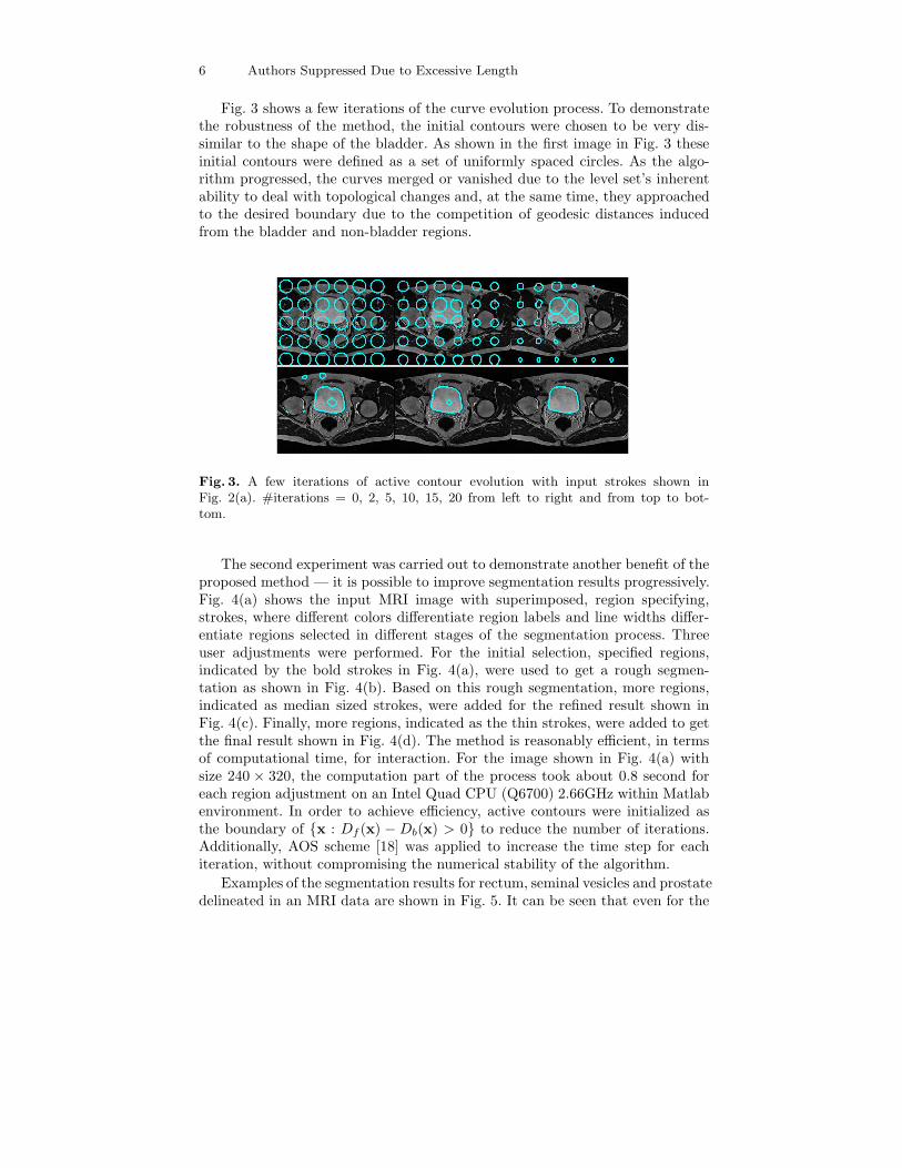
Fig. 3 shows a few iterations of the curve evolution process. To demonstratethe robustness of the method, the initial contours were chosen to be very dis-similar to the shape of the bladder. As shown in the first image in Fig. 3 theseinitial contours were defined as a set of uniformly spaced circles. As the algo-rithm progressed, the curves merged or vanished due to the level set’s inherentability to deal with topological changes and, at the same time, they approachedto the desired boundary due to the competition of geodesic distances inducedfrom the bladder and non-bladder regions.
Fig. 3. A few iterations of active contour evolution with input strokes shown inFig. 2(a). #iterations = 0, 2, 5, 10, 15, 20 from left to right and from top to bot-tom.
The second experiment was carried out to demonstrate another benefit of theproposed method — it is possible to improve segmentation results progressively.Fig. 4(a) shows the input MRI image with superimposed, region specifying,strokes, where different colors differentiate region labels and line widths differ-entiate regions selected in different stages of the segmentation process. Threeuser adjustments were performed. For the initial selection, specified regions,indicated by the bold strokes in Fig. 4(a), were used to get a rough segmen-tation as shown in Fig. 4(b). Based on this rough segmentation, more regions,indicated as median sized strokes, were added for the refined result shown inFig. 4(c). Finally, more regions, indicated as the thin strokes, were added to getthe final result shown in Fig. 4(d). The method is reasonably efficient, in termsof computational time, for interaction. For the image shown in Fig. 4(a) withsize 240 × 320, the computation part of the process took about 0.8 second foreach region adjustment on an Intel Quad CPU (Q6700) 2.66GHz within Matlabenvironment. In order to achieve efficiency, active contours were initialized asthe boundary of x : Df (x) − Db(x) > 0 to reduce the number of iterations.Additionally, AOS scheme [18] was applied to increase the time step for eachiteration, without compromising the numerical stability of the algorithm.
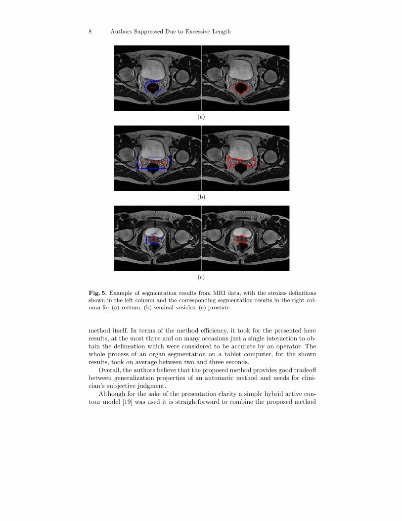
Examples of the segmentation results for rectum, seminal vesicles and prostatedelineated in an MRI data are shown in Fig. 5. It can be seen that even for the

Active Contour with User Interaction 7
(a) (b)
(c) (d)
Fig. 4. Illustration of progressive segmentation. (a) Original MRI image superimposedwith user specified regions (red for foreground and blue for background); (b) segmenta-tion result from the first region selection with bold strokes in (a) as specified regions; (c)segmentation result from the second region adjustment with medium stokes in (a) asadditional specified regions; (d) segmentation result from the third region adjustmentwith thin strokes in (a) as additional specified regions.
seminal vesicles, represented in the MRI by a complex textural pattern, an ac-curate segmentation can be obtained with only few approximate strokes.
The results obtained for organ segmentation from a CT data are shown inFig. 6. In this case the method preformed well even though the segmented organs,represented by similar intensity patterns, are of low contrast with very weakedges between organs.
Fig. 7 shows segmentation result of the prostate from a transrectal ultra-sound (TRUS) image. Again the method preformed well despite a high level ofnoise, typical for this imaging modality. It should be stressed that for all theresults shown in this section no image pre-processing was used. The methodworked directly ”out-of-the-box” with only active contour’s smoothing param-eter adjusted when segmenting different organs, though no changes were madeto the method’s design parameters when the same organ was segmented fromdifferent imaging modalities.
The paper does not contain a formal quantitative evaluation of the proposedmethod because due to the interactive nature of the method, obtained organsdelineation will always reflect user subjective judgment and therefore a compar-ison of the segmentation results with the ground truth data would be effectivelytesting inter- and/or intra- operator variability, thereby would not reflect on the
8 Authors Suppressed Due to Excessive Length
(a)
(b)
(c)
Fig. 5. Example of segmentation results from MRI data, with the strokes definitionsshown in the left column and the corresponding segmentation results in the right col-umn for (a) rectum, (b) seminal vesicles, (c) prostate.
method itself. In terms of the method efficiency, it took for the presented hereresults, at the most three and on many occasions just a single interaction to ob-tain the delineation which were considered to be accurate by an operator. Thewhole process of an organ segmentation on a tablet computer, for the shownresults, took on average between two and three seconds.
Overall, the authors believe that the proposed method provides good tradeoffbetween generalization properties of an automatic method and needs for clini-cian’s subjective judgment.
Although for the sake of the presentation clarity a simple hybrid active con-tour model [19] was used it is straightforward to combine the proposed method

Active Contour with User Interaction 9
(a)
(b)
(c)
Fig. 6. Example of the segmentation results from CT data for (a) rectum, (b) seminalvesicles and (c) bladder.
Fig. 7. Prostate segmented from the transrectal ultrasound image.
with the most of existing active contour methods to equip them with the pow-erful tool of progressive refinement while keeping specific characteristics of theoriginal method. Possible extensions can include active contour models incor-porating a prior knowledge of the organ shape [11], topological constraints [20]or texture by which organ is represented in a given imaging modality [21]. Themethod can be used with 3D data and with the help of Equ. (2) the method can

10 Authors Suppressed Due to Excessive Length
be adopted for simultaneous organ segmentation in registered multiple-modalitydata.
4 Conclusions
The paper describes a novel segmentation method which enable to incorporateuser specified regions into the active contour framework. The method can achieverobust results by evolving an active contour through competition of the forcesinduced by the specified regions and the input image providing an efficient wayto refine segmentation results progressively. The method has been shown tobe robust and able to cope with medical images of different modalities. Morespecifically it has been shown that the proposed method is an effective toolfor segmentation of prostate and proximate organ at risk in imaging modalitiestypically used in diagnosis and treatment of prostate cancer patients.
References
1. Kass, M., Witkin, A., Terzopoulos D.: Snakes: Active contour models. IJCV 1, 321-331 (1988)
2. Precioso, F., Barlaud M., Blu, T., Unser, M.: Robust real-time segmentation ofimages and videos using a smooth-spline snake-based algorithm. IEEE on ImageProcessing, 14, 910-924 (2005)
3. Osher, S.J., Fedkiw, R.: Level Set Methods and Dynamic Implicit Surfaces. Springer(2002)
4. Malladi, R., Sethian J.A., Vemuri, B.C.: Shape Modeling with Front Propagation:A Level Set Approach. PAMI 17, 158-175 (1995)
5. Chan, T.F, Vese, L.A.: Active contours without edges, IEEE on Image Processing,10, 266-277 (2001)
6. Caselles, V., Kimmel, R., Sapiro G.: Geodesic Active Contours. IJCV 22, 61-79(1997)
7. Cremers, D., Rousson, M., Deriche, R.: A Review of Statistical Approaches to LevelSet Segmentation: Integrating Color, Texture, Motion and Shape. IJCV 72, 195-215(2007)
8. Lankton, S., Tannenbaum, A.: Localizing Region-Based Active Contours. IEEE onImage Processing 17, 2029-2039 (2008)
9. Ni, K.Y., Bresson, X., Chan, T., Esedoglu, S.: Local Histogram Based SegmentationUsing the Wasserstein Distance. IJCV 84, 97-111 (2009)
10. Munim, H.E.A., Farag, A.A.: Curve/Surface Representation and Evolution Us-ing Vector Level Sets with Application to the Shape-Based Segmentation Problem.PAMI 29, 945-958 (2007)
11. Foulonneau, A., Charbonnier, P., Heitz, F.: Multi-reference Shape Priors for ActiveContours Source. ICJV 81, 68-81 (2009)
12. Zhang, Y., Sankar, R., Qian, W.: Boundary delineation in transrectal ultrasoundimage for prostate cancer. Computers in Biology and Medicine 37, 1591-1599 (2007)
13. Vikal, S., Haker, S., Tempany, C., Fichtinger, G.: Prostate contouring in MRIguided biopsy, MICCAI 2008 Prostate Workshop (2008)

Active Contour with User Interaction 11
14. Mahdavi, S.S., Salcudean, S.E., Morris, J., Spadinger, I.: 3D Prostate Segmentationin Ultrasound Images uisng Image Deformation and Shape Fitting, MICCAI 2008Prostate Workshop (2008)
15. Price, G., Moore, C.: Comparative Evaluation of a Novel 3D Segmentation Algo-rithm on In-Treatment Radiotherapy Cone Beam CT Images, Proceedings of theSPIE Conference on Medical Imaging, San Diego, USA, 6512(3), 38.1-38.11 (2007)
16. Sethian, J.A.: Level Set Methods and Fast Marching Methods. Cambridge Univer-sity Press (1998)
17. Hassouna, M.S., Farag, A.A.: MultiStencils Fast Marching Methods: A HighlyAccurate Solution to the Eikonal Equation on Cartesian Domains. PAMI 29, 1563-1574 (2007)
18. Weickert J., Romeny B.M.H., Viergever, M.A.: Efficient and reliable schemes fornonlinear diffusion filtering. IEEE on Image Processing, 7, 398-410 (1998)
19. Zhang, Y., Matuszewski, B.J., Shark L.-K., Moore, C.: Medical Image Segmen-tation Using New Hybrid Level-Set Method: IEEE International Conference onBiomedical Visualisation, MEDi08VIS, London, 9-11 July (2008)
20. Zhang, Y., Matuszewski, B.J: Multiphase active contour segmentation constrainedby evolving medial axes. IEEE International Conference on Image Processing,ICIP2009, Cairo (2009)
21. Histace, A., Matuszewski, B.J., Zhang, Y.: Segmentation of Myocardial Bound-aries in Tagged Cardiac MRI Using Active Contours: A Gradient-Based ApproachIntegrating Texture Analysis. International Journal of Biomedical Imaging (2009).
Copyright © 2022 FDOKUMEN