Bioelectrocatalytic oxidation and reduction of different ...
204
HAL Id: tel-03365929 https://tel.archives-ouvertes.fr/tel-03365929 Submitted on 5 Oct 2021 HAL is a multi-disciplinary open access archive for the deposit and dissemination of sci- entific research documents, whether they are pub- lished or not. The documents may come from teaching and research institutions in France or abroad, or from public or private research centers. L’archive ouverte pluridisciplinaire HAL, est destinée au dépôt et à la diffusion de documents scientifiques de niveau recherche, publiés ou non, émanant des établissements d’enseignement et de recherche français ou étrangers, des laboratoires publics ou privés. Bioelectrocatalytic oxidation and reduction of different substrates using carbon nanostructured electrodes Xiaohong Chen To cite this version: Xiaohong Chen. Bioelectrocatalytic oxidation and reduction of different substrates using carbon nanostructured electrodes. Inorganic chemistry. Université Grenoble Alpes, 2019. English. NNT : 2019GREAV076. tel-03365929
-
Upload
khangminh22 -
Category
Documents
-
view
4 -
download
0
Transcript of Bioelectrocatalytic oxidation and reduction of different ...

HAL Id: tel-03365929https://tel.archives-ouvertes.fr/tel-03365929
Submitted on 5 Oct 2021
HAL is a multi-disciplinary open accessarchive for the deposit and dissemination of sci-entific research documents, whether they are pub-lished or not. The documents may come fromteaching and research institutions in France orabroad, or from public or private research centers.
L’archive ouverte pluridisciplinaire HAL, estdestinée au dépôt et à la diffusion de documentsscientifiques de niveau recherche, publiés ou non,émanant des établissements d’enseignement et derecherche français ou étrangers, des laboratoirespublics ou privés.
Bioelectrocatalytic oxidation and reduction of differentsubstrates using carbon nanostructured electrodes
Xiaohong Chen
To cite this version:Xiaohong Chen. Bioelectrocatalytic oxidation and reduction of different substrates using carbonnanostructured electrodes. Inorganic chemistry. Université Grenoble Alpes, 2019. English. �NNT :2019GREAV076�. �tel-03365929�

THÈSE
Pour obtenir le grade de
DOCTEUR DE LA COMMUNAUTÉ UNIVERSITÉ GRENOBLE ALPES
Spécialité : Chimie inorganique et Bio inorganique
Arrêté ministériel : 25 mai 2016
Présentée par
Xiaohong CHEN Thèse dirigée par Serge COSNIER, Directeur de Recherche et co-encadrée par Fabien GIROUD, Université Grenoble Alpes préparée au sein du Laboratoire Département de Chimie Moléculaire dans l'École Doctorale Chimie et Sciences du Vivant
Oxydation et réduction bioélectrocatalytique de différents substrats à l'aide d'électrodes en carbone nanostructurées Bioelectrocatalytic oxidation and reduction of different substrates using carbon nanostructured electrodes
Thèse soutenue publiquement le 9 décembre 2019, devant le jury composé de :
Monsieur Guy ROYAL Professeur des Universités, Université Grenoble Alpes, Président
Madame Sophie TINGRY Directeur de Recherche, Institut Européen des Membranes, Rapporteur
Madame Carole CHAIX Directeur de Recherche, Institut des Sciences Analytiques, Rapporteur
Monsieur Laurent BOUFFIER Chargé de Recherche, Institut des Sciences Moléculaires, Université de Bordeaux, Examinateur Monsieur Serge COSNIER Directeur de Recherche, Université Grenoble Alpes, Directeur de thèse


Table of Contents
List of Figures ............................................................................................................... I
List of Tables .............................................................................................................. VI
Introduction générale .................................................................................................. 3
General Introduction ................................................................................................... 6
Chapter 1 Introduction .............................................................................................. 11
1.1 Background ......................................................................................................... 11
1.1.1 Fuel cells ....................................................................................................... 11
1.1.1.1 Principle of a fuel cell ................................................................................................... 11
1.1.1.2 Applications and limitations .......................................................................................... 12
1.1.2 Biofuel cells................................................................................................... 13
1.1.2.1 Microbial fuel cells ....................................................................................................... 13
1.1.2.2 Enzymatic fuel cells ...................................................................................................... 14
1.1.2.3 Mitochondria fuel cell ................................................................................................... 14
1.1.3 Enzymatic fuel cell ........................................................................................ 15
1.1.3.1 Principle of enzymatic biofuel cells .............................................................................. 15
1.1.3.2 Substrates and enzymes used in EFCs .......................................................................... 16
1.1.3.3 Characteristics of the biofuel cell .................................................................................. 19
1.1.3.4 Electroanalytical techniques for fuel cell characterization ............................................ 21
1.2 Enzymes immobilization and wiring ................................................................ 23
1.2.1 Immobilization methods ................................................................................ 23
1.2.2.1 Adsorption ..................................................................................................................... 23
1.2.2.2 Covalent bonding .......................................................................................................... 24
1.2.2.3 Encapsulation ................................................................................................................ 24
1.2.2.4 Cross-linking ................................................................................................................. 25
1.2.2.5 Affinity .......................................................................................................................... 25
1.2.2 Electron transfer mechanism ......................................................................... 25
1.2.3 Solubilized mediator and enzymes ................................................................ 28
1.2.4 Common enzymes used in EFCs ................................................................... 29
1.2.4.1 Glucose oxidase ............................................................................................................ 29
1.2.4.2 Flavin adenine dinucleotide-dependent glucose dehydrogenase ................................... 30
1.2.4.3 Lactate oxidase .............................................................................................................. 32
1.2.4.4 Bilirubin oxidase ........................................................................................................... 33
1.3 Carbon nanotube buckypaper electrode .......................................................... 34
1.3.1 Structures and properties of carbon nanotube ............................................... 35
1.3.2 Modification and functionalization of carbon nanotubes .............................. 37
1.3.2.1 Covalent method ........................................................................................................... 37
1.3.2.2 Non-covalent method .................................................................................................... 38

1.3.3 Carbon nanotube buckypaper ........................................................................ 39
1.3.3.1 Fabrication of buckypaper ............................................................................................. 40
1.3.4 Buckypaper-based biofuel cell ...................................................................... 41
1.4 Applications of enzymatic fuel cells .................................................................. 43
1.4.1 Implantable glucose/O2 biofuel cells............................................................. 43
1.4.2 Wearable lactate/O2 biofuel cells .................................................................. 45
1.4.3 Biosupercapacitor .......................................................................................... 46
References ................................................................................................................. 48
Chapter 2 Comparison of commercial and lab-made MWCNT buckypaper:
physicochemical properties and bioelectrocatalytic O2 reduction......................... 65
Résumé ...................................................................................................................... 65
2.1 Abstract ............................................................................................................... 69
2.2 Introduction ........................................................................................................ 69
2.3 Results and discussion ....................................................................................... 71
2.3.1 Physical properties of commercial and lab-made buckypaper ...................... 71
2.3.1.1 Scanning electron microscopy ...................................................................................... 72
2.3.1.2 Film thickness, specific surface area and pore size ....................................................... 72
2.3.1.3 X-ray photoelectron spectroscopy, SEM-Energy dispersive x-ray spectroscopy and
Raman spectroscopy ................................................................................................................. 73
2.3.1.4. Contact angle, surface profilometry and electrical conductivity .................................. 76
2.3.2 Electrochemical characterization of commercial and lab-made BPs ............ 77
2.3.3 Bioelectrocatalytic activity of BOx-modified commercial and lab-made BPs
................................................................................................................................ 81
2.4 Conclusion........................................................................................................... 88
2.5 Experimental section.......................................................................................... 89
2.5.1 Materials and reagents ................................................................................... 89
2.5.2 Characterization methods .............................................................................. 89
2.5.2.1 Morphology ................................................................................................................... 89
2.5.2.2 Physical ......................................................................................................................... 90
2.5.2.3 Spectroscopy ................................................................................................................. 90
2.5.2.4 Electrochemistry ........................................................................................................... 90
2.5.3 Procedures ..................................................................................................... 91
2.5.3.1 Preparation of buckypaper electrodes and bioelectrodes .............................................. 91
References ................................................................................................................. 92
Chapter 3 Use of alginate hydrogel coating to improve stability of carbon
nanotube bioanode for glucose oxidation ................................................................ 99
Résumé ...................................................................................................................... 99
3.1 Abstract ............................................................................................................. 102
3.2 Introduction ...................................................................................................... 102
3.3 Results and discussion ..................................................................................... 104
3.3.1 Effect of hydrogel coating ........................................................................... 104
3.3.1.1 Electrochemical characterization of the hydrogel-coated electrode ............................ 104
3.3.1.2 Storage stability of hydrogel coated electrode ............................................................ 106
3.3.2 Optimization of hydrogel fabrication parameters ....................................... 108
3.3.2.1 Comparison of hydrogels with different parameters ................................................... 108
3.3.2.2 Characterization of the bioelectrode with optimized hydrogel coating ....................... 111
3.4 Conclusion......................................................................................................... 113
3.5 Experimental Section ....................................................................................... 114
3.5.1 Materials and reagents ................................................................................. 114
3.5.2 Preparation of FAD-GDH modified buckypaper bioanodes ....................... 114
3.5.3 Preparation of alginate hydrogel-coated bioanodes .................................... 115
3.5.4 Optical microscopy ..................................................................................... 115
3.5.5 Electrochemical characterization ................................................................ 115
References ............................................................................................................... 117
Chapter 4 Stretchable and flexible buckypaper-based lactate biofuel cell for
wearable electronics ................................................................................................. 121
Résumé .................................................................................................................... 121
4.1 Abstract ............................................................................................................. 124
4.2 Introduction ...................................................................................................... 124
4.3 Results and discussion ..................................................................................... 126
4.3.1 Design of the EFC ....................................................................................... 126
4.3.2 Performance of the EFC .............................................................................. 128
4.3.3 Self-charging behavior of the EFC .............................................................. 131
4.3.4 Mechanical resilience of the EFC ............................................................... 132
4.3.5 On-body power generation .......................................................................... 134
4.4 Conclusion......................................................................................................... 136
4.5 Experimental section........................................................................................ 137
4.5.1 Materials and reagents ................................................................................. 137
4.5.2 Formulations................................................................................................ 138
4.5.2.1 Formulation of the interlayer PU ink .......................................................................... 138
4.5.2.2 Formulation of the PS-SEBS backbone polymer ink .................................................. 138
4.5.2.3 Formulation of the PVA sacrificial ink. ....................................................................... 138
4.5.2.4 Synthesis of the PB-PVA hydrogel .............................................................................. 138
4.5.2.5 Formulation of the SEBS insulation ink and Ag-SEBS conductive ink. ..................... 138
4.5.3 Procedures ................................................................................................... 139
4.5.3.1 “Island-bridge” electrode fabrication .......................................................................... 139
4.5.3.2 Fabrication of the polynorbornene-pyrene buckypaper .............................................. 139
4.5.3.3 Assembly of the buckypaper biofuel cell .................................................................... 140
4.5.3.4 Fabrication of the DC voltage booster circuit ............................................................. 140
4.5.4 Characterization methods ............................................................................ 141
4.5.4.1 Morphology ................................................................................................................. 141
4.5.4.2 Electrochemical measurements ................................................................................... 141
4.5.4.3 Mechanical resilience studies ...................................................................................... 142
4.5.4.4 On-body power generation .......................................................................................... 142
References ............................................................................................................... 143
Chapter 5 Redox-active glyconanoparticles as electron shuttles for mediated
electron transfer with bilirubin oxidase in solution .............................................. 149
Résumé .................................................................................................................... 149
5.1 Abstract ............................................................................................................. 154
5.2 Introduction ...................................................................................................... 154
5.3 Results and discussion ..................................................................................... 156
5.3.1 Characterization of NPs .............................................................................. 156
5.3.2 Oxygen reduction performance ................................................................... 161
5.4 Conclusion......................................................................................................... 167
5.5 Experimental Section ....................................................................................... 167
5.5.1 Materials and reagents ................................................................................. 167
5.5.2 Synthesis protocols ...................................................................................... 168
5.5.2.1 Synthesis of polystyrene-b-β-cyclodextrin (PSCD) .................................................... 168
5.5.2.2 Synthesis of bis-pyrene-2,2'-azino-bis(3-ethylbenzothiazoline-6-sulfonic acid)
(bis-pyrene-ABTS; P2ABTS) ................................................................................................. 168
5.5.2.3 Self-assembly of PSCDNP and PSCD-P2ABTSNP via nanoprecipitation .................... 168
5.5.3 Characterization protocols........................................................................... 169
5.5.3.1 Nanoparticle tracking analysis (NTA) ......................................................................... 169
5.5.3.2 Transmission electron microscopy (TEM) .................................................................. 169
5.5.3.3 Dynamic light scattering (DLS) .................................................................................. 169
5.5.3.4 UV-visible spectroscopy ............................................................................................. 170
5.5.3.5 Electrochemistry ......................................................................................................... 171
References ............................................................................................................... 172
Chapter 6 Conclusions and perspectives ............................................................... 177
6.1 Conclusions ....................................................................................................... 181

6.2 Perspectives....................................................................................................... 182
References ............................................................................................................... 184
Publications and presentations ............................................................................... 185
Acknowlegements ..................................................................................................... 187


I
List of Figures
Figure 1.1 Schematic representation of an H2/O2 fuel cell .................................................................... 11
Figure 1.2 Schematic representations of the mechanism of a catalytic reaction at an electrode of (left) a
fuel cell and (right) a biofuel cell (blue sphere: active site) ................................................................... 16
Figure 1.3 (A) Voltage-Current profile and (B) power-voltage profile of a fuel cell ............................. 20
Figure 1.4 Polarization curves and characteristics of a biocathode and a bioanode tested separately in a
three-electrode setup ............................................................................................................................... 22
Figure 1.5 Schematic representations of different enzymes immobilization methods ........................... 23
Figure 1.6 Structures of polymerizable monomers to form conductive polymer through chemical or
electrochemical oxidation ....................................................................................................................... 25
Figure 1.7 Structures of coupling agents commonly used for protein cross-linking ............................. 25
Figure 1.8 Schematic representations of different electron transfer mechanisms: (A) mediated electron
transfer and (B) direct electron transfer .................................................................................................. 26
Figure 1.9 Structure of (left) a subunit of the dimeric AnGOx (PDB: 3QVP) and (right) the FAD
cofactor ................................................................................................................................................... 30
Figure 1.10 Structure of (left) LOx from Aerococcus viridans (PDB ID: 2DU2)131
and (right) the FMN
cofactor ................................................................................................................................................... 32
Figure 1.11 Structure of (left) BOx from Myrothecium verrucaria (PDB ID: 2xll) and (right) the T1
and T2/T3 active sites ............................................................................................................................. 33
Figure 1.12 Schematic representations of molecular structure of (A) SWCNTs and (B) MWCNTs ..... 35
Figure 1.13 Schematic representations of rolling directions of graphene layer to form “arm-chair”,
“zig-zag” and chiral types of CNTs ........................................................................................................ 36
Figure 1.14 Scheme of esterification or amidation (peptide coupling if R is an enzyme) of oxidized
CNTs ....................................................................................................................................................... 38
Figure 1.15 Modification of CNTs by radical addition of a diazonium salt preformed or formed in situ
................................................................................................................................................................ 38
Figure 1.16 "π- π stacking" interaction between aromatic compounds and the CNT sidewall: A) pyrene
derivative; B) anthracene derivative and C) porphyrin derivative .......................................................... 39
Figure 2.1 SEM images showing (A, B) top-down and (C, D) cross-sectional views of (left) c-BP and
(right) l-BP ............................................................................................................................................. 72
Figure 2.2 Nitrogen adsorption and desorption isotherms of (left) c-BP and (right) l-BP ..................... 73
Figure 2.3 (Left) XPS survey spectra and (right) C1s high resolution spectra for (black) c-BP and (red)
l-BP substrates ........................................................................................................................................ 74
Figure 2.4 SEM-EDS analysis: SEM images showing (A, B) secondary electron detector

II
(Everhart-Thornley; ETD) for topographic visualization and (C, D) backscattered electron detector
(BSD) for chemical contrast of the impurities distribution of (left) c-BP and (right) l-BP. Global EDS
spectra of the same area as above for (E) c-BP and (F) l-BP .................................................................. 75
Figure 2.5 Raman spectrums of (black) c-BP and (red) l-BP of the region between 1000 and 2000 cm-1
................................................................................................................................................................ 76
Figure 2.6 Representative cyclic voltammograms recorded at (black) c-BP and (red) l-BP electrodes in
0.1 mol L-1
PB (pH 7.0) solution at 20 mV s-1
........................................................................................ 77
Figure 2.7 Representative cyclic voltammograms recorded at c-BP (black) and l-BP (red) electrodes in
1 mmol L-1
redox probe solutions: (A) Ru(NH3)63+/2+
, (B) FcMeOH+/0
, and (C) Fe(CN)63-/4-
in 0.1 mol
L-1
PB pH 7.0, and (D) Fe3+/2+
in 0.5 mol L-1
H2SO4. Scan rate: 20 mV s-1
............................................ 79
Figure 2.8 Representative cyclic voltammograms for (A) unmodified, (B) H0.6 and (C) H5 modified
c-BPs (black) and l-BPs (red) with adsorbed BOx at the electrode surfaces in quiescent (dashes)
Ar-saturated or (lines) O2-saturated in pH 7.0 PB solution (1 mV s-1
, 1st scan displayed) ..................... 82
Figure 2.9 Resolved bilirubin oxidase protein structure from Myrothecium verrucaria highlighting four
arginine residues located near the T1 copper centre of the enzyme. (PDB code: 2XLL) ....................... 83
Figure 2.10 Representative cyclic voltammograms for (black) c-BP-H10 and (red) l-BP-H10 with
adsorbed BOx in quiescent (dashes) Ar-saturated and (lines) O2-saturated 0.1 mol L-1
PB solution at pH
7.0 (1 mV s-1
, 1st scan displayed) ........................................................................................................... 87
Figure 2.11 Representative cyclic voltammograms for l-BP-H5 with adsorbed BOx in quiescent
Ar-saturated 0.1 mol L-1
PB at pH 7 (1 mV s-1
, 2nd
scan displayed) showing the T1 copper centre at Ep =
0.490 V vs. SCE ...................................................................................................................................... 87
Figure 3.1 Alginate chain conformations. ............................................................................................ 103
Figure 3.2 (A) Schematic representation of the hydrogel-coated bioanode(yellow layer: enzyme
solution, blue layer: hydrogel coating); (B) representative cyclic voltammograms (CVs) of (black)
uncoated and (blue) hydrogel-coated bianodes in 0.2 mol L-1
pH 7.0 HEPES in the (dash) absence and
the (solid) presence of 50 mmol L-1
glucose (scan rate: 1 mV s-1
); (C) chronoamperograms (CAs)
recorded at (black) uncoated and (blue) hydrogel-coated bianodes at Eapp= 0.2 V vs. Ag/AgCl at
different glucose concentrations in Ar saturated HEPES buffer pH 7.0 at 150 rpm; (D) plots of average
current density obtained from (C) for different glucose concentrations recorded at (black) uncoated and
(blue) hydrogel-coated bianodes. ......................................................................................................... 105
Figure 3.3 CVs recorded on (red) day 0 and (black) day 5 for (A) uncoated and (B) hydrogel-coated
bianodes in 0.2 mol L-1
pH 7.0 HEPES in the (dash) absence and the (solid) presence of 50 mmol L-1
glucose (scan rate: 1 mV s-1
). ............................................................................................................... 106
Figure 3.4 (A) CVs recorded on day 0 and for (black) uncoated and (blue) hydrogel-coated BPPLQ in
0.2 mol L-1
pH 7.0 HEPES (scan rate: 1 mV s-1
); (B) evolution of PLQ surface coverage for (black)
uncoated and (blue) hydrogel-coated BPPLQ as a function of storage time; (C) overlay of CV scans
recorded on day 0 in the absence of glucose in HEPES buffer for (black) uncoated BPPLQ, (blue)

III
hydrogel-coated BPPLQ-gel, (green) uncoated bioanode BPPLQ-FADGDH and (red) hydrogel-coated
bioanode BPPLQ-FADGDH-gel electrodes. ........................................................................................... 108
Figure 3.5 CVs recorded on (red) day 0 and (black) day 5 for (A) uncoated and (B) CNT incorporated
hydrogel-coated bianodes in 0.2 mol L-1
pH 7.0 HEPES in the (dash) absence and the (solid) presence
of 50 mmol L-1
glucose (scan rate: 1 mV s-1
). ...................................................................................... 109
Figure 3.6 Optical images of the CNT incorporated hydrogel-coated bioanode in (left) wet and (right)
dry conditions. ...................................................................................................................................... 111
Figure 3.7 (A) Schematic representation of the CNT incorporated hydrogel-coated bioanode (yellow
layer: enzyme solution, blue layer: CNT/hydrogel coating); (B) representative CVs of (black) uncoated
and (blue) CNT incorporated hydrogel-coated bianodes in 0.2 mol L-1
pH 7.0 HEPES in the (dash)
absence and the (solid) presence of 50 mmol L-1
glucose (scan rate: 1 mV s-1
); (C) chronoamperograms
recorded at (black) uncoated and (blue) CNT incorporated hydrogel-coated bianodes at Eapp= 0.2 V vs.
Ag/AgCl at different glucose concentrations in Ar saturated HEPES buffer pH 7.0 at 150 rpm; (D) plots
of average current density obtained for different glucose concentrations recorded at (black) uncoated
and (blue) CNT incorporated hydrogel-coated bianodes. ..................................................................... 111
Figure 3.8 (A) CAs recorded at (black) uncoated and (blue) CNT incorporated hydrogel-coated
bianodes at Eapp= 0.2 V vs. Ag/AgCl for 16 h with 50 mmol L-1
glucose in Ar saturated HEPES buffer
pH 7.0 at 150 rpm; CVs recorded (red) before and (black) after 16 h continuously operation for (B)
uncoated and (C) CNT incorporated hydrogel-coated bianodes in 0.2 mol L-1
pH 7.0 HEPES in the
(dash) absence and the (solid) presence of 50 mmol L-1
glucose (scan rate: 1 mV s-1
). ....................... 113
Figure 4.1 (A) Photograph of the stretchable EFC device on a human arm, (zoom) schematic
illustration of the skin-mountable wearable EFC device; (B, C) Photographs of the EFC under
stretching and bending, respectively; (D) Schematics of the redox energy generation from sweat lactate
oxidation at the anode and O2 reduction at the cathode by EFC. .......................................................... 127
Figure 4.2 Schematic illustration of (A) the screen-printing process; (B) designed patterns for different
screen-printing layer; (C) Zoom of the interconnect “bridge” and electrode “island” structure (red
squares in (B)). ..................................................................................................................................... 128
Figure 4.3 (A) SEM image of buckypaper functionalized with pyrene-polynorbornene. (B) LSV of the
BP bioanode in the presence of (black) 0 mmol L-1
and (red) 15 mmol L-1
lactate in 0.5 mol L-1
PB
(pH 7.4) at 5 mV s-1
. (C) LSV of the BP biocathode in air-equilibrated buffer with (black) 0 mmol L-1
and (red) 15 mmol L-1
lactate at 5 mV s-1
. (D) The power density versus voltage plots for the
stretchable lactate EFC under different lactate concentrations (0, 5, 10 and 15 mmol L-1
) in 0.5 M PB
(pH 7.4). (E) Plots showing the stability of the stretchable EFC in the presence of 15 mmol L-1
lactate
at different times up to 48 hours. (F) The calculated relative change of power density at 0.55 V over 48
hours, based on the data in (E). ............................................................................................................ 130
Figure 4.4 Plots of power density versus voltage of (green) stretchable buckypaper EFC and (left)(blue)
screen-printed EFC based on current collector modified with enzymes and (right)(blue) screen-printed
EFC based on CNT ink (formula from reported literature) modified with enzymes. ........................... 130

IV
Figure 4.5 (A) CV of EFC in the presence of (black) 0 mmol L-1
and (red) 15 mmol L-1
lactate in 0.5
mol L-1
PB (pH 7.4) at 50 mV s-1
. (B) Overlay of potential profiles obtained from EFC discharge at 2, 5,
10, 15, 20 and 25 mA cm-2
over 10 ms. (C) Plot of the calculated pulse power density as a function of
the discharge current density. (D) Potential profile of the EFC during a discharge at 5 mA cm-2
at 33 Hz
frequency. ............................................................................................................................................. 131
Figure 4.6 (A) GCD curves of the EFC at different charge-discharge current density (0.1, 0.2, 0.5, 1.0
mA cm-2
). (B) The calculated corresponding areal capacitance. .......................................................... 132
Figure 4.7 Mechanical resilience studies: Image of the wearable EFC (A) before and (B) after 20%
stretching. (C) Resistance profile obtained during 20% stretching, (inset) zoom of resistance
fluctuations. (D) Current density output profile of the EFC under a 33 kΩ load in PVA gel immersed in
15 mmol L-1
lactate, (inset) zoom of current density fluctuations. (E) Plots of EFC power density
versus voltage under 20% stretching for 0, 20, 40, 60, 80 and 100 cycles in 15 mmol L-1
lactate. (F)
The calculated relative change of power density at 0.55 V over 100 stretching cycles. ....................... 134
Figure 4.8 (A) Power output profile under 510 Ω load during an on-body experiment. (B) The circuit
schematics for using the flexible and stretchable epidermal EFC patch to power an LED via a flexible
DC-DC convertor. (C) Image of on-body experiment set up with a EFC mounted on the arm of the
volunteer. (D) and (E) Imagesof the LED switched on and off, respectively. ...................................... 135
Figure 4.9 (A) and (B) Voltage output profile under 0.2s pulsed discharge and continuous discharge
during exercise, respectively. ................................................................................................................ 135
Figure 4.10 (A) The circuit diagram and (B) the photo of the prepared flexible voltage boosting circuit.
.............................................................................................................................................................. 136
Figure 5.1 (A) Schematic representation of the self-assembly of bis-pyrene-ABTS encapsulated
glyconanoparticles. (B) TEM imaging and (C) hydrodynamic diameter distribution by NTA of
PSCD-P2ABTSNP. ............................................................................................................................... 156
Figure 5.2 Number-weighted hydrodynamic diameter distribution by nanoparticle tracking analysis of
PSCDNP. It is noted that the PSCD-P2ABTSNP assemblies are ca. twice the size of the PSCDNP
assemblies suggesting that ca. 23 = 8 individual nanoparticles come together in solution to form the
PSCD-P2ABTSNP clusters. ................................................................................................................... 157
Figure 5.3 (A) DLS autocorrelation function (g(2)
– 1) measured at 90° and relaxation time distribution
of PSCD-P2ABTSNP. (B) UV-visible spectra for (red) PSCD-P2ABTSNP, (black) PSCDNP and
(pink·-) H2O-P2ABTS. (C) CVs at glassy carbon of as-prepared (red) PSCD-P2ABTSNP and (black)
PSCDNP at 100 mV s-1
. (D) Corresponding plots of peak current vs. the square root of the scan rate for
PSCD-P2ABTSNP. ................................................................................................................................ 158
Figure 5.4 (A) UV-visible absorption spectra of (i) PSCD-P2ABTSNP and (ii) PSCD-P2ABTSNP with
11 nmol L-1
BOx. (B) UV-visible absorption spectra of (i) 2, (ii) 4, (iii) 5, (iv) 6, (v) 7 and (vi) 9 μmol
L-1
of (solid line) ABTS2-
and (dashed line) ABTS•-
with 11 nmol L-1
BOx. (C) Linear calibration curves
determined from the spectra in (B) according to Beer-Lambert Law. The calibration plot performed
with ABTS•- at λmax = 414 nm was used to eliminate the possible interference of pyrene and served as a

V
second method to estimate the concentration. ...................................................................................... 159
Figure 5.5 Plots of peak current recorded at glass carbon electrode vs. (A) square root of the scan rate
and (B) scan rate for as-prepared PSCD-P2ABTSNP solution for scan rates between 1 mV s-1
and 2 V s-1
.
.............................................................................................................................................................. 160
Figure 5.6 CV recorded at a GCE in 0.1 mol L-1
PB pH 7 at 100 mV s-1
to test for the presence of
adsorbed species after performing a scan rate study in as-prepared aqueous PSCD-P2ABTSNP solution
(ca. 15 potential cycles from 0 V to 0.8 V) then rinsing the electrode with 0.1 mol L-1
PB pH 7. ....... 161
Figure 5.7 Ten consecutive CVs recorded of as-prepared aqueous PSCD-P2ABTSNP solution at GCE
(pH = 5.6) at 100 mV s-1
. ...................................................................................................................... 161
Figure 5.8 CVs recorded at GCE at 5 mV s-1
(pH = 5.6) with (black--) argon saturation and (red-) O2
saturation with BOx for (A) saturated bis-pyrene-ABTS in PB, (B) as-prepared PSCDNP (pH = 5.9), (C)
as-prepared PSCD-P2ABTSNP, (D) BOx only, and (E) ABTS in PB. [BOx] = 3.5 μmol L-1
and
[mediator] = 6.5 μmol L-1
(˂ 6.5 μmol L-1
for saturated bis-pyrene-ABTS). ....................................... 162
Figure 5.9 DLS analysis of as-prepared PSCD-P2ABTSNP and diluted PSCD-P2ABTSNP solutions
used to investigate catalytic as a function of mediator concentration. Dilutions with estimated
bis-pyrene-ABTS concentrations were prepared in purified water: 3.25 μmol L-1
(2 times), 2.17 μmol
L-1
(3 times), 1.3 μmol L-1
(5 times) and 0.65 μmol L-1
(10 times). At least 3 DLS measurements were
performed per solution type. ................................................................................................................. 163
Figure 5.10 Plots of catalytic current versus mediator concentration for as-prepared and diluted
PSCD-P2ABTSNP solutions (black) and ABTS2-
in phosphate buffer (pH = 5.6) (red) vs. mediator
concentration. [BOx] = 0.5 μmol L-1
. Current measured from amperograms recorded at 0.2 V vs. SCE
after 600 seconds with O2 saturation and stirring at 100 rpm. .............................................................. 163
Figure 5.11 (A) Schematic representation of the intra-electron transfer chain between redox
nanoparticles and BOx. (B, C) Plots of limiting current as a function of substrate concentration with
lines of best fit to Equation 5.3 for (B) ABTS2-
and (C) P2ABTSNP solutions. [BOx] = 10 nmol L-1
and
[med] = 6.5 μmol L-1
. Current measured from amperograms at 0.2 V vs. SCE. ................................... 164
Figure 5.12 CVs recorded at GCE at 5 mV s-1
(pH = 5.6) with (black--) argon saturation and (red-) O2
saturation with BOx for visibly aggregated PSCD-P2ABTSNP after leaving the sample at room
temperature in air for ≥ 6 months. .................................................................................................... 164
Figure 5.13 Chronoamperograms recorded for 1800 s at Eapp = 0.2 V vs. SCE at GCE in
oxygen-saturated solution of (A) PSCD-P2ABTSNP as-prepared pH = 5.6 with BOx, (B) ABTS2-
in
phosphate buffer (pH = 5.6) with BOx, and (C) BOx only in phosphate buffer (pH = 5.6) on (i) day 0,
(ii) day 1, (iii) day 2. [BOx] = 3.5 μmol L-1
. ........................................................................................ 165
Scheme 5.1 Synthetic pathway for preparation of polystyrene-b-β-cyclodextrin (PSCD). .................. 168
Figure 5.14 (A) Spectrophotometric enzyme assay recorded at λ = 414 nm for 300 s in 50 µmol L-1
ABTS2-
in phosphate buffer (pH = 5.6) with (i) 7.3 nmol L-1
BOx and (ii) without BOx. (B) Fitting of
the linear region of the curve (i) shown in (A) for a minimum of 2 min. ............................................. 170

VI
List of Tables
Table 1.1 Comparison of different fuel cells. ......................................................................................... 12
Table 1.2 List of fuels found in EFCs, their product, the enzymes responsible for their oxidation and
the cofactors of the enzyme .................................................................................................................... 16
Table 1.3 List of oxidants used in EFCs, their product, the enzymes responsible for their reduction and
the cofactors of the enzyme .................................................................................................................... 19
Table 1.4 Characteristics and performances of buckypaper-based enzymatic biofuel cell .................... 42
Table 1.5 Characteristics and performances of implantable glucose/O2 enzymatic biofuel cells .......... 44
Table 2.1 Surface area and pore size data from N2 sorption isotherms for commercial and lab-made BP
................................................................................................................................................................ 73
Table 2.2 XPS elemental analysis for c-BP and l-BP surfaces ............................................................... 74
Table 2.3 Midpoint potential, peak separation, electroactive area and heterogeneous rate constant for
FcMeOH0/+
, [Ru(NH3)6]3+/2+
, [Fe(CN)6]3-/4-
, and Fe2+/3+
obtained at GCE, l-BP and c-BP electrodes .... 78
Table 2.4 Electrochemical characterization data for hemin modified c-BP and l-BP electrodes from 0.6,
5, 10 mmol L-1
modifier solutions .......................................................................................................... 84
Table 2.5 Catalytic performance data for unmodified and hemin modified c-BP and l-BP electrodes .. 86
Table 3.1 Electrochemical and catalytic parameters for uncoated and hydrogel-coated BPPLQ electrodes
and BPPLQ-GDH electrodes recorded on day 0 and day 5. ................................................................... 106
Table 3.2 Electrochemical and catalytic parameters for uncoated BPPLQ-GDH electrodes and
BPPLQ-GDH coated with different hydrogel configurations recorded on day 0 and day 5 (MWCNTs
with 90 % carbon purity are used here). ............................................................................................... 110
Table 4.1 Performance of wearable lactate-based EFCs reported in the literatures ............................. 129
Table 5.1 Catalytic parameters from cyclic voltammetry at glassy carbon cathodes with 3.5 μmol L-1
BOx and mediator in solution under oxygen saturated conditions ....................................................... 162
Table 5.2 Stability data obtained during 1800 s on two days from single-potential amperometry at Eapp
= 0.2 V vs. SCE at glassy carbon cathodes with 3.5 μmol L-1
BOx and mediator in solution under
oxygen purging conditions ................................................................................................................... 166

1
General
Introduction

2

3
Introduction générale
Les biopiles sont un sujet de recherche brûlant depuis des décennies dans le but
d’établir des sources d’énergie de remplacement pour atténuer les problèmes
environnementaux causés par les combustibles fossiles classiques. Une sous-catégorie
des biopiles, les biopiles enzymatiques (EFC) ont beaucoup attiré l'attention ces
derniers temps, alors que les scientifiques tentaient de récupérer de l'énergie
directement du corps humain. L’intérêt des enzymes comme catalyseurs réside dans le
fait qu’ils peuvent fonctionner dans des conditions physiologiques complexes et
utiliser diverses sources de carburant durables, notamment le sucre contenu dans les
fluides corporels, qui sont très intéressantes pour alimenter de futurs dispositifs
électroniques implantables et portables dans le corps ou à la surface du corps. Dans
cette configuration, au moins deux enzymes rédox sont nécessaires; un à l'anode pour
oxyder le combustible et un à la cathode pour réduire un oxydant.
Les nanotubes de carbone (CNTs) sont utilisés comme matériaux d'électrode en
raison de leur surface spécifique élevée et de leurs propriétés électroniques
exceptionnelles. Par ailleurs, le faible diamètre des CNTs permet d’approcher de plus
près le site actif des enzymes, ce qui pourrait théoriquement améliorer le câblage
électrique des protéines rédox. Buckypaper (BP) est un matériau ressemblant à du
papier formé par un réseau de CNTs enchevêtrés et est maintenu par les forces de Van
der Waals. Les BPs peuvent être facilement préparés en laboratoire par filtration de
suspensions de nanotubes de carbone pour former des films uniformes. Ils sont
minces, légers, hautement conducteurs et faciles à fonctionnaliser, ce qui en fait
d'excellents candidats comme matériau d'électrode pour les applications de piles à
combustible.
Le but de cette thèse est d'explorer les formulations, les caractérisations et les
applications pratiques des buckypapers dans les biopiles enzymatiques.
Le premier chapitre est une revue de littérature sur les connaissances générales et
les derniers rapports scientifiques permettant de bien comprendre la bioélectrochimie
et en particulier les EFCs. Il est structuré en quatre sections. La première section
présente le contexte général des piles à combustible et des biopiles. Une description
plus détaillée du principe de fonctionnement et des caractéristiques des EFCs est
donnée. La deuxième section présente les méthodes d'immobilisation d'enzymes et les
mécanismes de transfert d'électrons des enzymes. Une introduction détaillée de

4
certaines enzymes communément utilisées dans les EFCs est également présentée. La
troisième section concerne la structure et les propriétés du papier mâché en nanotube
de carbone en tant que matériau d'électrode. Ce chapitre se termine par la présentation
de différentes applications des EFCs et des résultats les plus récents dans ces
domaines de recherche.
Dans le chapitre 2, les buckypapers commerciaux obtenus auprès d'un fournisseur
et de buckypapers fabriqués en laboratoire ont été comparés afin d'établir leurs
propriétés pour une utilisation future en tant que bioélectrodes avancées. Les
propriétés physiques des films de nanotubes de carbone ressemblant à du papier ont
été caractérisées par différentes techniques. Les propriétés électrochimiques ont été
étudiées par voltamétrie en l'absence et en présence de sondes redox. La réduction
bio-électrocatalytique de l'oxygène a été évaluée avec des neutrophages modifiés au
fer-protoporphyrine après immobilisation de la bilirubine oxydase (BOx).
Le chapitre 3 explore l'utilisation de l'hydrogel d'alginate comme couche protectrice
afin d'améliorer la stabilité de la bioanode pour l'oxydation du glucose. La bioanode
oxydante du glucose a été préparée en immobilisant la glucose déshydrogénase (GDH)
dépendante de la flavine adénine dinucléotide (FAD) sur un papier gabarit de
laboratoire fonctionnalisé avec la 1,10-phénanthroline-5,6-dione en tant que médiateur.
De l'hydrogel préparé à partir de différents paramètres de fabrication a été déposé sur
la surface de l'électrode en buckypaper. L'effet du revêtement d'hydrogel sur le
stockage et la stabilité opérationnelle de la bioanode a été évalué par voie
électrochimique.
Au chapitre 4, une biopile à combustible lactate/O2, extensible et flexible, a été
réalisée en utilisant un papier mâché pour électrode. La BP flexible a été fabriquée en
tant que matrice d'immobilisation pour la lactate oxydase (LOx) à l'anode et BOx à la
cathode. Pour répondre aux exigences des composants électroniques portables, les
électrodes BP fonctionnalisées ont été assemblées sur un collecteur de courant
sérigraphié extensible avec une configuration «îlot-pont», qui confère au EFC une
excellente stabilité de performance en étirement. La stabilité mécanique et les
performances énergétiques de l'appareil ont été examinées.
Le cinquième chapitre présente brièvement une autre configuration d'électrodes
pour la réaction bioélectrocatalytique dans laquelle les deux médiateurs et les
enzymes sont en solution. Des glyconanoparticules nouvellement synthétisées
permettent la solubilisation d'un médiateur redox non soluble dans l'eau pour donner

5
des nanoparticules à activité rédox. Dans ce chapitre, la préparation et la
caractérisation détaillée de nanoparticules ont été présentées et leur utilisation comme
navettes électroniques pour les oxydoréductases a été étudiée.
Enfin, la thèse se termine par une conclusion de ce travail et une discussion sur les
perspectives futures.

6
General Introduction
Biofuel cells have been a hot research topic for decades aiming to establish
alternative energy options to alleviate the environmental problems caused by
conventional fossil fuels. A subcategory of biofuel cells, enzymatic biofuel cells
(EFCs) have drawn a lot of attention lately as scientists are trying to harvest energy
directly from the human body. The beauty of using enzymes as catalysts is that they
can operate at complex physiological conditions and utilize various sustainable fuel
sources, especially sugar in body fluids, which are very interesting for powering
future implantable and wearable electronic devices inside the body or on the surface
of the skin. In such configuration, at least two redox enzymes are required; one at the
anode to oxidize the fuel and one at the cathode to reduce an oxidant.
Carbon nanotubes (CNTs) are used as electrode materials due to their high specific
surface area and exceptional electronic properties. Besides, the thin diameter of CNTs
makes it possible to approach more closely the active site of enzymes, which could
theoretically enhance the electrical wiring of redox proteins. Buckypaper (BP) is a
paper-like material formed by entangled CNTs network and is held together by Van
der Waals forces. BPs can be easily prepared in labs by filtration of carbon nanotubes
suspensions to form uniform films. They are thin, lightweight, highly conductive and
easy to functionalize, which makes them great candidates as electrode material for
fuel cell applications.
The aim of this thesis is to explore the formulations, characterizations and practical
applications of buckypapers in enzymatic biofuel cells.
The first chapter is a literature survey on general knowledge and latest scientific
reports to get a good grasp on bioelectrochemistry and especially on EFCs. It is
structured in four sections. The first section introduces the general context of fuel
cells and biofuel cells. A more detailed description of the working principle and
characteristics of EFCs are given. The second section presents enzyme
immobilization methods and electron transfer mechanisms of enzymes. A detailed
introduction of some commonly used enzymes in EFCs is also given. The third
section concerns the structure and properties of carbon nanotube buckypaper as
electrode material. This chapter ends with the presentation of different applications of
EFCs and state-of-the-art results in these research fields.
In chapter 2, commercial buckypapers obtained from a supplier and

7
laboratory-made buckypapers have been compared to establish their properties for
future use as advanced bioelectrodes. The physical properties of the paper-like carbon
nanotube films were characterized with different techniques. The electrochemical
properties were investigated by voltammetry in the absence and presence of redox
probes. Bioelectrocatalytic oxygen reduction was evaluated with iron-protoporphyrin
modified buckypapers after immobilization of bilirubin oxidase (BOx).
Chapter 3 explores the use of alginate hydrogel as a protective layer to improve
stability of bioanode for glucose oxidation. The glucose oxidizing bioanode was
prepared by immobilizing flavin adenine dinucleotide (FAD) dependent glucose
dehydrogenase (GDH) onto lab-made buckykpaper functionalized with
1,10-phenanthroline-5,6-dione as the mediator. Hydrogel prepared from different
fabrication parameters was deposited onto buckypaper electrode surface. The effect of
hydrogel coating on the storage and operational stability of the bioanode was
evaluated electrochemically.
In chapter 4, a stretchable and flexible lactate/O2 biofuel cell was realized using
buckypaper as the electrode material. Flexible BP was fabricated as the
immobilization matrix for lactate oxidase (LOx) at the anode and BOx at the cathode.
To fulfill the strain-enduring requirement of wearable electronics, the functionalized
BP electrodes were assembled onto a stretchable screen-printed current collector with
an “island–bridge” configuration, which endows the EFC with excellent performance
stability under stretching condition. The mechanical stability and power performance
of the device were examined.
The fifth chapter briefly introduces an alternative electrode configuration for
bioelectrocatalytic reaction where both mediators and enzymes are in solution. Newly
synthesized glyconanoparticles enable the solubilization of non-water soluble redox
mediator to give redox-active nanoparticles. In this chapter, the preparation and
detailed characterization of nanoparticles were presented and their use as electron
shuttles for oxidoreductases was investigated.
Finally, the thesis ends with a conclusion of this work and a discussion of future
perspectives.

8

9
Chapter 1:
Introduction

10

11
Chapter 1 Introduction
1.1 Background
1.1.1 Fuel cells
In modern society, the majority of world energy comes from fossil fuels, which
contains petroleum, natural gas and coal. Despite their relatively large availability on
earth, their stocks are limited. Their extraction requires large infrastructures and can
eventually lead to the contamination of the area. Furthermore, greenhouse gases are
released from the combustion of these non-renewable fuels. This leads to huge
environmental impacts and without a doubt contributes to the current climate change.
With the continuously growing energy demand and decreasing reserve of fossil fuels,
there has been much interest in developing environmentally friendly and renewable
energy sources without greenhouse gas emission. Compared with combustion of fossil
fuels, fuel cells represent a more efficient and more environmentally friendly power
generation system that transforms chemical energy stored in various sustainable fuels
(H2, natural gas, sugar, etc…) into electricity without intermediate steps.
1.1.1.1 Principle of a fuel cell
Figure 1.1 Schematic representation of an H2/O2 fuel cell
Figure 1.1 depicts the general scheme of a H2/O2 fuel cell, exploiting H2 as fuel and
O2 as oxidant, which is one of the most studied systems in fuel cells. In general, fuel
cells are electrochemical devices comprised of anodes, cathodes and electrolytes that
12
can convert chemical energy into electrical current via redox reactions. In this case,
H2 is oxidized by the electrocatalyst at the anode. The released electrons then flow in
the external circuit and the generated protons diffuse through the electrolyte toward
the cathode, where oxidants (O2, H2O2) are reduced with the combination of electrons
and protons. The generated electricity can then be used to do work. The only product
in this process is water, making it exceptionally attractive for the development of
clean power sources.
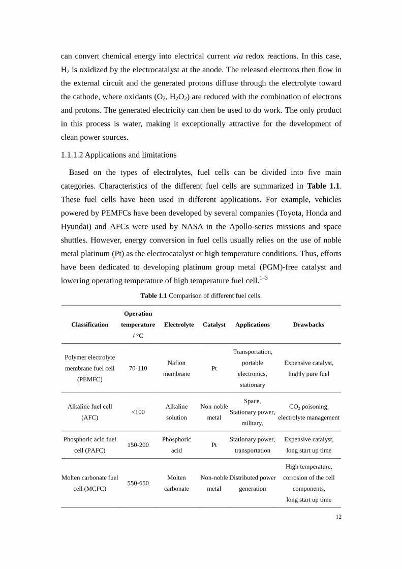
1.1.1.2 Applications and limitations
Based on the types of electrolytes, fuel cells can be divided into five main
categories. Characteristics of the different fuel cells are summarized in Table 1.1.
These fuel cells have been used in different applications. For example, vehicles
powered by PEMFCs have been developed by several companies (Toyota, Honda and
Hyundai) and AFCs were used by NASA in the Apollo-series missions and space
shuttles. However, energy conversion in fuel cells usually relies on the use of noble
metal platinum (Pt) as the electrocatalyst or high temperature conditions. Thus, efforts
have been dedicated to developing platinum group metal (PGM)-free catalyst and
lowering operating temperature of high temperature fuel cell.1–3
Table 1.1 Comparison of different fuel cells.
Classification
Operation
temperature
/ °C
Electrolyte Catalyst Applications Drawbacks
Polymer electrolyte
membrane fuel cell
(PEMFC)
70-110 Nafion
membrane Pt
Transportation,
portable
electronics,
stationary
Expensive catalyst,
highly pure fuel
Alkaline fuel cell
(AFC) <100
Alkaline
solution
Non-noble
metal
Space,
Stationary power,
military,
CO2 poisoning,
electrolyte management
Phosphoric acid fuel
cell (PAFC) 150-200
Phosphoric
acid Pt
Stationary power,
transportation
Expensive catalyst,
long start up time
Molten carbonate fuel
cell (MCFC) 550-650
Molten
carbonate
Non-noble
metal
Distributed power
generation
High temperature,
corrosion of the cell
components,
long start up time

13
Solid oxide fuel cell
(SOFC) 500-800
Ceramic
oxide
Cathode:
perovskite
Anode:
cermet
Distributed power
generation
High temperature,
corrosion of the cell
components,
long start up time
A subcategory of fuel cells, biofuel cells (BFCs), have attracted considerable
attention as they use biological entities as electrocatalysts instead of traditional
expensive and nonrenewable noble metal-based catalysts. Compared with
conventional fuel cells, BFCs are capable to operate at mild conditions, neutral pH,
and in complex media. Biological catalysts are renewable resources, which makes
BFC ideal candidate to replace commercial lithium battery for low power portable
applications. The concept of BFCs will be further elaborated in the following part.
1.1.2 Biofuel cells
Depending on the nature of biocatalysts, biofuel cells can be categorized into
microbial fuel cells,4,5
mitochondrial biofuel cells6 and enzymatic biofuel cells.
7 The
different characteristics of the biocatalysts therefore determine the different
operational conditions and applications of these BFCs.
1.1.2.1 Microbial fuel cells
Microbial fuel cells (MFCs) utilize whole microorganisms as electrocatalysts.
These microorganisms (bacteria, yeast or archaea) contain enzyme cascades that can
oxidize carbohydrates completely to carbon dioxide, which endows microbial fuel
cells with high energy density. Since enzymes can be regenerated by the living
organism, the life time of MFCs can be up to order of years.8 However, the mass
transfer and electron transfer processes of MFCs involve crossing the cell membrane,
resulting in low power density, which remains the major roadblock for
commercialization.9 Besides, given the living nature of biocatalysts, it is necessary to
separate the cathodic and anodic compartments to avoid cross-reaction. In 2005,
Bergel et al. developed a microbial-based biocathode for oxygen reduction by
growing a marine biofilm on a stainless steel electrode.10
Later, Rabaey et al. reported
a complete MFC with both microbial-based biocathode and bioanode, the MFC
produced a maximum power density of 30.3 μW cm-2
.11
As a result of the underlying challenges, microbial fuel cell is not economically
competitive as a power source.12
Given the large size and long lifetime of MFCs, a

14
promising application is wastewater treatment combined with electricity
generation.13,14
Ieropoulos et al. demonstrated the first example of electricity
generation from urine using MFCs.15
The same group later conducted field trials on
campus and a music festival, where they demonstrated the feasibility of MFCs for
stable power generation and urine treatment simultaneously.16
1.1.2.2 Enzymatic fuel cells
Enzymatic fuel cells and microbial fuel cells are the two most studied groups of
BFCs. The former group employs oxidoreductases as the catalysts, which are a group
of redox active enzymes that can catalyze the electron transfer process that occurs
during the substrate cleavage. Oxidoreductases are important in biotechnology as they
can be explored in practical applications such as biosensors and biofuel cells.
Compared with microorganisms, their small size and the absence of cell membranes
facilitate both mass and electron transfer. The specificity of enzymes towards their
substrates usually eliminates the need for membrane for compartmentalization, which
greatly simplifies the design and miniaturization of devices. The first EFC was
developed by Yahiro et al. in 1964, where glucose oxidase (GOx) was used for
glucose oxidation at the anode and platinum was used as catalyst for oxygen reduction
at the cathode.17
Tremendous improvements have been made ever since then with the
power density increases to the order of mW cm-2
.7,18
The biggest challenge of EFCs is their limited stability, ranging from days to
weeks,18,19
which can be ascribed to the fragile nature of purified enzymes. Another
challenge lies in the low power density. In contrast to MFCs, enzymes usually
perform one-step oxidation of the biofuel, leading to low energy efficiency. On the
other hand, the power performance is greatly influenced by the operating environment
conditions (pH, temperature and inhibitors). One of the contributing factors is the
limited substrate availability. In addition, many reported EFCs are tested in buffer
solutions, where oxygen reduction currents are small due to the slow diffusion and
low concentrations of dissolved O2 (∼0.25 mmol L-1
at 25 °C) in aqueous solutions.20
1.1.2.3 Mitochondria fuel cell
Mitochondrial fuel cell has been exploited in recent years as an alternative solution
to overcome the limitations of MFCs and EFCs. Mitochondria, regarded as the
powerhouse of the cell, are organelles present in eukaryotic cells. As part of the living

15
cells, mitochondria contain readily multiple enzymes that can deeply oxidize some
organic substrates (pyruvate,21
fatty acids,22
and amino acids6), providing similar
energy efficiency as MFCs. Mitochondria are considered as a compromise between
microorganisms and enzymes. Fuel cells utilizing these species exhibit higher power
density than MFCs due to more facile mass transfer. Mitochondrial fuel cells also
possess longer lifetime than EFCs due to the presence of mitochondria membranes. In
2008, Arechederra and Minteer demonstrated the first mitochondria-based bioanode
that can completely oxidize pyruvate into carbon dioxide.21
By coupling with a Pt
cathode, the biofuel cell achieved a power density of 203 μW cm-2
and a lifetime of
60 days.21
However, power densities obtained in the reported literatures are still lower
than the theoretical values.6,21,22
The following works mostly done by Minteer’s group
have been more driven in using mitochondria for self-powered explosive sensing.23–25
1.1.3 Enzymatic fuel cell
1.1.3.1 Principle of enzymatic biofuel cells
Regardless of the type of biocatalysts, BFCs share similar operation principle as
conventional fuel cells (see chapter 1.1.1.1). One big distinction between FC and BFC
is the different electron exchange properties. The difference of the electrode reaction
mechanism between FC and BFC is illustrated in Figure 1.2. Compared with
conventional metal catalysts used in FCs, enzymes are macromolecules with their
redox centers buried in non-conductive protein shell. The low active sites density and
long electron tunneling distance therefore hinders the electrical coupling between
enzymes and electrode surfaces.26
In general, the reaction at an enzyme-modified electrode can be separated into three
regions (Figure 1.2): 1) mass transfer between bulk electrolyte and catalyst active
sites; 2) enzyme-catalyzed reaction; 3) electron transfer between active sites and the
electrode. To increase the overall current output of the reaction, researchers are
focusing on lowering the energy barrier of the rate limiting step. Thorough
investigation of the reaction mechanism is needed to identify the rate limiting step,
followed by optimization of the parameters involved in the reaction. The
improvement in the current density of the bioelectrode can be implemented in
different research areas. For example, catalytic current can be increased by utilization
of nanomaterial-based electrodes (directly linked to the increase in surface area) for

16
higher enzyme loading on the electrode. To improve the overall current and fuel cell
efficiency, engineering aspects also need to be considered such as optimization of the
electrode spacing, matching of the cathode and anode performance, etc.
Figure 1.2 Schematic representations of the mechanism of a catalytic reaction at an electrode of (left) a
fuel cell and (right) a biofuel cell (blue sphere: active site)
1.1.3.2 Substrates and enzymes used in EFCs
Although the power density of EFCs are not comparable to conventional
PGM-based fuel cells, a big advantage of EFCs is that it opens up the possibility to
harvest chemical energy from various and abundant organic compounds using
biosourced and renewable electrocatalysts. The choice of fuel and oxidant determines
the corresponding enzymes used in the system. Although there is a wide range of fuels
that can be used for EFCs, factors such as energy density, cost, storage and safety of
fuels have limited the option for actual applications. The fuels used in EFCs are
mostly saccharides, H2, alcohol and some intermediates present in metabolism. A list
of representative fuels and enzymes is shown in Table 1.2.
Table 1.2 List of fuels found in EFCs, their product, the enzymes responsible for their oxidation and
the cofactors of the enzyme
Fuels Half-Reactions Enzymes Cofactors Reference
Aldehyde AldehydeAcid Aldehyde dehydrogenase
(AlDH)
Nicotinamide adenine
dinucleotide Marchitti et al.
27

17
(NAD+)
Cellobiose Cellobiose
Cellobionolactone
Cellobiose DH (CDH)
Flavin adenine
dinucleotide
(FAD)/Heme
Ludwig et al.28
Ethanol
Methanol AlcoholAldehyde Alcohol DH (ADH) NAD
+
Theorell and
McKinley-McKee29
Formic acid HCOOHCO2 Formate DH NAD+ Ferry et al.
30
Fructose D-fructose
5-Keto-D-fructose Fructose DH (FDH) FAD/Heme Adachi et al.
31
Glucose D-Glucose
D-glconolactone
Glucose oxidase (GOx) FAD
Ferri et al.32
Glucose DH (GDH)
FAD or NAD+ or
Pyrroloquinoline
quinone (PQQ)
Lactate LactatePyruvate
Lactate oxidase (LOx)
Flavin
mononucleotide
(FMN)
Maeda-Yorita et
al.33
Lactate DH (LDH) NAD+ Holbrook et al.
34
Hydrogen H2 2H++2e
- Hydrogenase (H2ase) [NiFe] or [FeFe] Adams et al.
35
As a clean fuel with high energy density, hydrogen has also been widely studied in
EFCs.36,37
Hydrogenases (H2ase) are metalloenzymes with active sites composed of
Ni-Fe or Fe-Fe that can catalyze the oxidation of H2 at low overpotential.38
Compared
with platinum, H2ase has high efficiency, can operate at mild conditions and is not
susceptible to carbon monoxide poisoning.39
However, H2ase can be (strongly)
deactivated in the presence of oxygen.40
Researchers have been working on the
isolation and characterization of O2-tolerant H2ase from Ralstonia eutropha to
overcome the limitations.41,42
Another strategy is to integrate the O2-sensitive H2ase
into a protective layer composed of viologen-based redox polymer for shielding the
enzyme from O2.43
The most commonly used fuels in EFCs are saccharides due to their low costs,
availability, renewability and safety. Many sugars including fructose, lactose and
polysaccharides can be used as fuels. Among these sugars, glucose is the most widely
used fuel due to its presence in human body fluids at moderate concentration,44
which
makes it an ideal candidate as the power source for implantable electronic devices.
18
Glucose oxidation can be catalyzed by several enzymes such as glucose oxidase or
glucose dehydrogenase. Since the first glucose/O2 EFC developed in 1964,17
GOx has
been the most used enzyme for glucose oxidation due to its high stability and low
cost.45–47
However, GOx is an oxygen-sensitive enzyme that uses oxygen as a natural
electron acceptor and can produce hydrogen peroxide in the electrocatalytic process.48
The as-produced H2O2 has been shown to be detrimental to cathodic enzyme
activity.48
Furthermore, the competitive reaction with O2 implies that a fraction of the
electrons produced during the catalytic oxidation of glucose will deviate from flowing
to the cathode via interconnects, instead going to O2 and resulting in a decrease of the
cell performance.
Glucose dehydrogenases (GDH), on the other hand, are oxygen insensitive
enzymes. Three specific GDH have been discovered so far and are classified based on
their redox active center and each of them has its own specificity. NAD-dependent
GDH (NAD-GDH) utilizes NAD+ as the cofactor. Although the low apparent redox
potential of this cofactor (E°NAD+/NADH = -0.56 V vs. SCE at pH 7.0)
49 can be seen as
an appealing trait for an anodic enzyme, the use of such enzyme has some limitations.
First, NAD is not bound to the protein. Hence it has to be added to the electrolyte
which increases the cost of the device and the possibility for crossover reaction at the
cathodic side. Additionally, despite its low redox potential, the regeneration of NAD+
requires high overpotential at unmodified electrodes.50
There have been more and
more interests in using PQQ-dependent GDH (PQQ-GDH) and FAD-dependent GDH
(FAD-GDH) with bound cofactors. It should be noted that PQQ-GDH displays broad
substrate specificity and therefore is not suitable for sensing applications.32
As for the reduction reaction at the cathode, oxygen is the most commonly used
oxidant. Laccase (Lac)51
and bilirubin oxidase (BOx)52
are the two most used
enzymes for bioelectrocatalytic four-electron reduction of oxygen. Both of them
belong to the group of multi-copper oxidases (MCOs), which contains at least four
copper atoms acting as redox active centers and can reduce oxygen with small
overpotential.53
There are other enzymes such as copper efflux oxidase (CueO),54
polyphenol oxidase55
(PPO) and cytochrome oxidase56
(CytOx) that can reduce
oxygen. Nevertheless, they are rarely used to construct biocathode due to high
overpotential.54,55,57
In certain cases, hydrogen peroxide has been explored as oxidant
at the cathode, which involves a two-electron reduction reaction catalyzed by
peroxidase.58
Oxidants and enzymes used for biocathode are

19
summarized in Table 1.3.
Table 1.3 List of oxidants used in EFCs, their product, the enzymes responsible for their reduction and
the cofactors of the enzyme
Oxidants Half-Reactions Enzymes Cofactors Reference
O2 O2+ 4H++4e
- 2H2O
Lac
Cu
Tarasevich et al.59
BOx Tsujimura et al.60
CueO Miura et al.54
PPO Reuillard et al.55
Cyt Ox Cu/Fe/Heme Katz et al.56
H2O2 H2O2 + 2H++2e
- 2H2O
Horseradish
peroxidase (HRP) Fe/Heme Elouarzaki et al.
58
A more detailed introduction on each redox enzymes used during the course of this
thesis is given in section 1.2.4.
1.1.3.3 Characteristics of the biofuel cell
Open circuit voltage (OCV) and power density are two key parameters for
evaluation of the fuel cell performance. OCV describes the potential difference
between the cathode and the anode at zero current, which is the maximum voltage of
the fuel cell. OCV corresponds to the cell voltage at equilibrium (Eeq), which can be
calculated from the change in Gibbs free energy of reaction (∆Geq) in the galvanic cell
by61
𝐸𝑒𝑞 = −∆𝐺𝑒𝑞 𝑛𝐹⁄ (1.1)
where n is the number of electrons, and F is the Faradaic constant. In H2/O2 fuel cell,
the overall chemical reaction is:
𝐻2(𝑔) +1
2𝑂2(𝑔) → 𝐻2𝑂(𝑙) (1.2)
According to Equation 1.1, OCV is calculated to be 1.23 V in the standard
condition.19
In electrochemistry, OCV is measured by open circuit potentiometry. This
is similar to connecting the fuel cell to an infinite load resistance. The actual OCV is
usually lower than the theoretical Eeq due to the nature of the redox centers of the
enzymes or the redox potential of the mediators. When current starts to flow in the
cell, the measured cell potential (Emeasured) will depart from its equilibrium value. The

20
term that describes the potential loss is called overpotential (η). There are three types
of overpotential:62
the activation overpotential (ηact), the ohmic overpotential (ηiR) and
the mass transfer overpotential (ηmt). The relation between Emeasured and Eeq can be
expressed as:
𝐸𝑚𝑒𝑎𝑠𝑢𝑟𝑒𝑑 = 𝐸𝑒𝑞 − 𝜂𝑎𝑐𝑡−𝜂𝑖𝑅 − 𝜂𝑚𝑡 (1.3)
Figure 1.3 (A) Voltage-Current profile and (B) power-voltage profile of a fuel cell
The contribution of each type of overpotential to the shape of voltage-current curve is
shown in Figure 1.3. ηact describes the activation energy required to overcome the
energy barrier of the electrode-electrolyte interface. ηiR is related to the overall
resistance of the fuel cell including electrodes, electrolyte and electrical connections.
ηmt origins from the mass transfer limitation of the reaction at limiting currents. For a
fuel cell with a defined Eeq, Equation 1.3 suggests the strategy to maximize cell
voltage through minimization of all three types of potential. For example, ohmic
overpotential can be improved by using high conductivity material. Mass transfer
overpotential can be improved by incorporating porous electrode materials to
facilitate substrate diffusion.
The power (or power density) is another key parameter to evaluate fuel cell
performances. Power profile of EBFC is often described by power-voltage curve
(Figure 1.3), which is obtained from fuel cell polarization curve, based on the
equation:
𝑃 = 𝐸 × 𝐼 (1.4)
Polarization curve is often obtained by performing linear sweep voltammetry (LSV).
In order to limit the non-faradaic current contribution originated from the electrode
capacitance, slow scan rates (≤ 1 mV s-1
) are required for the LSV method. Another

21
option is to use the backward scan of a cyclic voltammetry (CV) performed at a slow
scan rate. A decent experiment to measure power should show a small difference
between the forward and the backward of CV scan. This provides crucial information
on diffusion limitation that could arise during experiments. Finally, to exclude the
power from capacitive current contribution and verify no diffusion limitation is
encountered, power profile can also be obtained by connecting to a variable load or
applying a series of constant potential. The value of the potential/current will be
recorded after stabilization of the system (depending on the time scale needed during
fuel cell operation).
Power-voltage curve reveals the maximum power delivered by the fuel cell and the
optimum operation voltage for maximizing power density. However, such
representation often hides useful information such as diffusion limitation and does not
display short circuit currents. As a summary, an ideal fuel cell characterization profile
should include both its polarization and its power curve.
1.1.3.4 Electroanalytical techniques for fuel cell characterization
Different electroanalytical methods can be used to study the bioelectrochemical
reactions taking place at the bioelectrode in the fuel cell. Electrochemical
measurement cells can be arranged in two-electrode or three-electrode configuration.
Cathode and anode are usually characterized separately as working electrode in
three-electrode configuration to obtain the individual characteristics of the half-cells
constituting the whole device. When the fuel cell is assembled, it is usually studied in
two-electrode configuration with cathode as the working electrode and anode as the
combined reference/counter electrode to ensure a positive readout of the OCV. Hence,
the monitored reaction being the reduction reaction, negative currents will be recorded
in this configuration. The behavior of the fuel cell in two-electrode configuration can
then be explained by combining the characteristics of the two electrodes. Commonly
used techniques for characterization of EFCs are potential sweep, amperometry and
potentiometry techniques.
For potential sweep techniques, the potential of the working electrode is modified
linearly from potential E1 to E2 with a constant scan rate (mV s-1
). When the potential
reaches E2, the scan stops for linear sweep voltammetry while for cyclic voltammetry,
a reverse scan is performed typically back to the initial potential E1. The resulting
current between the counter electrode and the working electrode is recorded to

22
produce the current-voltage curve called linear sweep voltammogram or cyclic
voltammogram. Figure 1.4 shows linear sweep voltammograms of a bioanode and a
biocathode, which are usually used to demonstrate the enzyme catalyzed oxidation
and reduction reaction. The polarization curves allow for the determination of the
onset redox potential for electrocatalysis, the anodic or cathodic overpotentials and
the identification of the limiting electrode in the system (electrode showing the lowest
current value).
Figure 1.4 Polarization curves and characteristics of a biocathode and a bioanode tested separately in a
three-electrode setup
Cyclic voltammetry can be used to examine the electron transfer kinetics of redox
processes. For example, for immobilized redox mediators, the electron transfer rate
constant can be evaluated by analysis of the peak potential separation and scan rate
dependence using the Laviron method.63
The current curves recorded using potential sweep techniques contain faradaic
current and non-faradaic current as the potential is shifted continuously. Amperometry
is often used to eliminate the capacitive current contribution by applying a constant
potential and record the current as a function of time. The current-time curve, also
named as chronoamperograms, can be used to examine the operational stability of the
electrode.
High surface area nanomaterials are often used to construct bioelectrodes, which
possess high electrostatic double-layer capacitance. Therefore, the EFC displays
charge storing capability. The capacitance of the device can be characterized using
galvanostatic charge-discharge measurements. A constant current is applied to charge
and discharge the EFCs and the capacitance can be calculated based on the following

23
equation:
𝐶 = 𝐼∆𝑡 ∆𝑈⁄ (1.5)
where ∆U is the voltage drop during the interval ∆t in Equation 1.5 when current I is
applied.
1.2 Enzymes immobilization and wiring
1.2.1 Immobilization methods
In the bioelectrochemistry research field, enzyme immobilization is an essential
step in studying electron transfer processes of biological entities. By immobilizing
enzymes on the designed electrode support, enzyme stability and electron transfer
efficiency can be improved. More specifically, to increase the overall power
performance of enzymatic fuel cells, the amount of enzyme immobilized on the
electrode support plays a crucial role. For bioelectronics applications, enzyme
immobilization is often required to build miniaturized devices. Different types of
immobilization techniques have been studied and are summarized in the following
section (Figure 1.5).64
Figure 1.5 Schematic representations of different enzymes immobilization methods
1.2.2.1 Adsorption
An easy and widely used method is simple adsorption of enzymes on electrode
surface. It can be done by directly drop-casting enzyme solution on electrode surface
or by incubating the electrode in enzyme solution.65
Enzymes are immobilized on the
electrode via the non-specific interactions involving hydrophobic, electrostatic or Van
der Waal’s forces between the biomolecule and the electrode. This method is simple
and most of the enzyme activity is preserved due to low change of the

24
three-dimensional structure of the protein. However, it suffers from poor stability with
enzyme desorption from the surface due to the weak interaction forces.
1.2.2.2 Covalent bonding
Enzymes can also be immobilized through covalent coupling to the electrode
surface via chemical reaction to form stable covalent bond. This method can prevent
enzyme detachment from the surface but it also irreversibly decrease enzyme activity
due to chemical modification or conformational change of the biomolecule.66
To form covalent bonds between the enzyme and the electrode surface, prior
modification of the electrode support is necessary to introduce functional groups such
as diazonium,67
carboxylic,68
thiol,69
epoxy70
and maleimide71
groups. These
functional groups can be coupled to the primary amine groups of lysine residues or
thiol groups of cysteine residues. Recently, site-specific modifications of enzymes
have been developed in order to immobilize the redox proteins with favored
orientation.72
1.2.2.3 Encapsulation
Encapsulation involves the immobilization of enzymes in a three-dimensional
matrix. Conducting polymers have been widely used for enzyme encapsulation.73
By
mixing enzymes and the monomers together, followed by chemical or electrochemical
oxidation, enzymes can be retained in the three-dimensional environment. Figure 1.6
shows examples of commonly used conducting polymers. Other encapsulation
matrices consist of non-conductive polymers (chitosan,74
alginate,73
Nafion,75
…) and
inorganic sol-gel composite.76
Encapsulation is able to retain large amount of
enzymes and preserve enzyme activity in the matrix, however, the thickness of the
film needs to be well-tuned to reduce diffusion barrier. In addition, enzyme leakage
and detachment of the matrix can also happen and therefore limit electrode stability.

25
Figure 1.6 Structures of polymerizable monomers to form conductive polymer through chemical or
electrochemical oxidation
1.2.2.4 Cross-linking
Enzyme cross-linking is done through the assistance of a cross-linker to form
aggregates on the electrode surface. Commonly used cross-linkers such as
glutaraldehyde, poly(ethylene glycol) diglycidyl ether (PEGDGE) and activated ester
can cross-link enzymes by reacting with the amine groups of enzymes (Figure 1.7).
Recently, there are growing interests in using redox polymer hydrogel as enzyme
immobilization and wiring matrix.77,78
PEGDGE is able to cross-link with the amine
groups of enzymes and imidazole groups of redox polymers. This method has the
similar drawback as covalent bonding, both of which can denature enzymes leading to
lower enzyme activity.
Figure 1.7 Structures of coupling agents commonly used for protein cross-linking
1.2.2.5 Affinity
Another method to immobilize enzymes exploits affinity interactions between
specific functional groups on the electrode surface and affinity tags on proteins to
form supramolecular assemblies. Affinity interactions rely on affinity partners that can
bind selectively together. Commonly affinity partners include lectin-carbohydrate,79
avidin-biotin,80
cyclodextin-adamantane81
and metal cation-chelator.82
One of the
biggest advantages of this method is its selectivity, which allows controlled enzyme
immobilization. Besides, the non-covalent nature of affinity bonding can minimize
conformational change of enzymes. However, this method involves relative complex
procedures for the introduction of specific tags for affinity interactions.
1.2.2 Electron transfer mechanism
One of the key parameters to construct high-power enzymatic biofuel cells is to

26
achieve efficient electron transfer or “electrical wiring” between enzymes and
electrodes. Electron transfer between the redox centers of the enzymes and the
electrodes can be realized via direct electron transfer (DET) and mediated electron
transfer (MET), as illustrated in Figure 1.8. According to Marcus’s theory, DET rate
decreases exponentially as the electron donor-acceptor distance increases.83
To realize
DET between enzyme and the electrode, the electron transfer path should be as short
as possible. Page et al. demonstrated that electron tunneling is unlikely to happen for
redox centers spacing beyond 14 Å in the proteins.84
In many cases, the redox centers
of enzymes are deeply buried in the protein structure and therefore electron transfer
via DET is not always possible.85
Figure 1.8 Schematic representations of different electron transfer mechanisms: (A) mediated electron
transfer and (B) direct electron transfer
Figure 1.8A shows the mechanism for MET. Small redox molecules are used to
shuttle electrons between the enzyme active site and the electrode. For anodic reaction,
the enzyme first reacts with the substrate (the fuel) and is re-oxidized to its active
form by the mediator. Hence at the end of a single catalytic cycle, the redox mediator
is in its reduced state. Then, the mediator re-oxidizes to its oxidized state by
transferring electrons to the electrode. If the potential is chosen correctly, the mediator
is continuously cycling between its reduced and its oxidized forms, producing anodic
current for the substrate oxidation. Dioxygen, a natural electron acceptor for many
oxidases, has been used as mediator in the first generation biosensors.86,87
To avoid
the oxygen competition with cathode reduction reaction, artificial molecules are
explored as mediators. Common mediators include ferrocene derivatives, ferricyanide,
transition metal complexes, organic dyes, quinone compounds and conducting salts.88
When choosing redox mediators for the enzymes, the following criteria should be

27
fulfilled:88
1. The redox mediator must have a suitable redox potential close to the redox
potential of the enzyme active site. The redox potential should have an
optimized compromise between electromotive driving force and onset potential
of the reaction. In addition, if the redox potential is too positive (negative for
cathode), it may lead to unwanted catalysis with other species in the electrolyte.
2. The reaction of the mediator should be reversible.
3. The mediator should be stable in both reduced and oxidized forms.
4. The mediator should exhibit fast electron exchange rate with both the enzyme
and the electrode.
The most important group of redox mediators in EFC and biosensors are probably
osmium-based complexes, which are introduced by Heller et al. in his pioneer works
and are still fast developing.89,90
Based on the ligand used for complexation of
osmium, they can be anchored on the polymer backbone to form redox polymer.
Osmium-based redox polymers are the most widely used redox polymers and their
redox potential can be finely tuned through modification of the ligand around the
coordination sphere.91,92
The polymer backbones can be modified to introduce
additional functionalities such as cross-linking capability with enzymes. Besides
electron transfer, redox polymers also serve as immobilization matrix, where enzymes
are immobilized through entrapment, chemical cross-linking or electrostatic
interactions depending on the nature of the polymer. Other redox polymers bearing
ferrocene,93
cobaltocene,94
viologen,95
phenothiazine96
and quinone97
have also been
reported and used for fabrication of bioelectrodes.
Mediators can operate in solution or immobilized on the electrode surface. To
eliminate the need for compartmentalization, both mediators and enzymes are usually
immobilized on the electrode surface. Although MET can provide high current by
increasing the number of enzymes electrically connected to the electrode, the
utilization of mediator inevitably reduces the cell voltage as the reaction takes place at
potentials where the redox mediator can undergo to its own oxidation or reduction for
the oxidation of the fuel or the reduction of the oxidant, respectively. The use of these
mediators also introduces concerns such as mediator stability and toxicity.
Another electron transfer mechanism is the direct electron transfer (DET, Figure
1.8B), for which the electrode works as the electron acceptor/donor without the need
of an additional redox mediator. This means the reactions start at the standard
28
apparent potential of the redox proteins, which can maximize the cell voltage. DET is
regarded as a more elegant way for electron transfer as it eliminates the issues with
mediator listed before. This mechanism was first discovered in 1977, when DET with
cytochrome c on different electrodes were reported.98,99
Later, more enzymes were
discovered to be able to undergo DET (e.g. laccase,59
fructose dehydrogenase,100
cellobiose dehydrogenase101
). In general, DET is more likely to be realized on
enzymes with redox active metallocenters (iron-sulfur cluster,102
copper center,103
heme104
) located near their surface due to a shorter distance for electron tunneling.104
To realize DET on electrode surface, the material and modification of the conductive
material also play a crucial role. Although DET method is reasonably simple, only a
maximum of monolayer enzymes can be connected. If the immobilized enzymes are
not well oriented with their active sites facing electrode surface, some of the enzymes
will not be involved in the bioelectrocatalytic reaction, therefore reducing the catalytic
current. Hence, the electrode surface has to be tailored in order to improve the specific
orientation of the enzyme. DET between bilirubin oxidase and the tailored electrode
surface is described in section 1.2.4.4.
1.2.3 Solubilized mediator and enzymes
In most biosensors and enzymatic biofuel cells, both mediators and enzymes are
immobilized on electrode surface to achieve high power densities. However, with this
configuration, it is difficult to restore the bioelectrode activity when either mediators
or enzymes gradually lose their activity.105
As previously described, enzymes
desorption and leaching can be an issue for the non-covalent immobilization methods
while covalent attachment of enzymes can reduce enzyme activity. High surface
coverage of mediators and enzymes are also necessary to increase power densities,
but it can be hard to achieve on limited electrode surface area, and also expensive for
commercial concern.
An alternative solution is to use solubilized mediators and enzymes, which opens
up a new strategy to prolong EFC lifetime through exchange of the fuel cell
compartment with fresh active materials. The main advantage of this approach is that
a solution-based biofuel cells can be envisioned where nanostructured electrodes,
mediators and enzymes solution will be introduced inside a chamber permeable to
substrates. Previously, Bourourou et al. developed a buckypaper electrode modified

29
with a bis-pyrene derivative redox mediator, the electrode showed high catalytic
current density and stability up to two weeks with laccase in solution.106
Zhu and
Zhang reported a high power density closed biobattery with non-immobilized
enzymes and mediators.107
In this thesis, a polymeric nanoparticle based system is developed by using
redox-active glyconanoparticles as supramolecular vehicles for introduction of a wide
range of insoluble catalyst-mediators into fuel cells. The use of redox active
glyconanoparticles also avoids the issue of cross-reaction between cathodic and
anodic compartment due to their large size. The development and characterization of
the redox active glyconanoparticels and their use as electron shuttles for biocatalytic
reaction are detailed in Chapter 5.
1.2.4 Common enzymes used in EFCs
Enzymes are biological macromolecules that work as catalysts in metabolic
processes in living organisms. Most enzymes are proteins, only a few are RNA
molecules. The enzyme activity and specificity rely on their three-dimensional
structures, with an active site surrounded by a protein backbone. In
bioelectrochemistry, oxidoreductases are a group of enzymes that are particularly
interesting as they catalyze redox reactions. These enzymes usually require the use of
either inorganic ions or organic molecules as their cofactors. The different enzymes
used for the design of EFCs during this PhD program will be introduced in the
following section.
1.2.4.1 Glucose oxidase
Glucose oxidase (GOx, EC 1.1.3.4) has been one of the most studied
oxidoreductases due to its application for glucose oxidation since the development of
the first glucose biosensor108
and the first glucose based EFC.17
GOx is a flavoprotein
consisting of two identical subunits with a flavin adenine dinucleotide (FAD) cofactor
(Figure 1.9). GOx can be naturally produced by some fungi and insects, among which
the most commonly used one is GOx from Aspergillus Niger (An).109
Crystal structure
of AnGOx revealed a three dimensional size of 7×5.5×8 nm and a molecular weight of
160 kDa.110
This enzyme catalyzes the two-electron oxidation of β-D-glucose to
D-glucono-δ-lactone (which then hydrolyzes to gluconic acid) with the FAD reduced
to FADH2. Molecular oxygen is a natural electron acceptor utilized by GOx to

30
re-oxidize FADH2 back to FAD with the generation of hydrogen peroxide. The
reaction is written as below:
β-D-glucose + FAD(GOx) D-glucono-δ-lactone + FADH2(GOx)
FADH2(GOx) + O2 FAD(GOx) + H2O2 (1.6)
Figure 1.9 Structure of (left) a subunit of the dimeric AnGOx (PDB: 3QVP) and (right) the FAD
cofactor
For electron transfer between GOx and the electrode, many researchers have
claimed to establish DET on various electrode materials (e.g. carbon nanotube,111
graphene112
) based on the observed redox peaks of FAD/FADH2 near -0.47 V vs. SCE
at pH 7.0. However, structural studies suggest that DET is difficult to achieve due to
the fact that GOx is highly glycosylated (16% to 25%)113
and there is a long electron
transfer distance between FAD and the periphery of GOx (13 to 18 Å).114
The redox
peaks observed probably belong to free FAD disassociated from GOx, which are no
longer enzymatically active.115
Nevertheless, there are some convincing reports on
realizing DET on GOx. Liu et al. achieved DET by modifying the electrode with
molecular wire.116
In 2009, Courjean et al. deglycosylated AnGOx and observed
glucose oxidation at a low potential of -0.49 V vs. Ag/AgCl at pH 7.4.117
Given the
difficulty of achieving DET, most glucose based bioelectrodes utilize MET for
electrical connection with the electrode. In 1993, Ohara et al. demonstrated the use of
osmium-based redox polymer [Os(2,2'-bipyridine)2(PVI)10Cl]+/2+
for electrical wiring
of GOx.77
Since then, osmium based redox polymers have been widely used as
mediators for GOx to construct glucose biosensor and glucose biofuel cell.118–120
1.2.4.2 Flavin adenine dinucleotide-dependent glucose dehydrogenase
Although GOx has been the gold standard for glucose biosensing, its oxygen
sensitivity can cause measurement errors due to oxygen level fluctuations in sample

31
solutions (saliva, plasma, blood, etc…). There has been growing interest in
developing glucose biosensors using FAD-dependent glucose dehydrogenase
(FAD-GDH, EC 1.1.99.10) for the two electron oxidation of glucose.121–123
This
enzyme contains the same cofactor as GOx, but it does not use O2 as electron acceptor,
which makes it an ideal candidate for all type of self-monitoring glucose biosensors or
glucose biofuel cell. FAD-GDH can be expressed in bacteria, fungi and some insects.
Among them, fungi-derived FAD-GDH has received the most attention due to its
substrate specificity toward glucose.32
Fungal FAD-GDHs have been identified in
Aspergillus subspecies with structures ranging from monomeric to
homooligomeric.121,124
Despite broad interest in FAD-GDH, structural information
and their availability remain scarce.
A recent study by Yoshida et al. reveals that the overall structure and active site
structure of fungal FAD-GDH are similar to GOx, with the FAD cofactor deeply
buried below the protein surface (~1.4 nm).125
Therefore, it is difficult to achieve DET
between FAD-GDH and the electrode. Muguruma et al. reported DET signal of
FAD-GDH on gold electrode by using de-bundled single walled carbon nanotube.126
It
is worth noting that in this work the oxidation current in the presence of glucose starts
at a relatively high potential of 0.1 V vs. Ag/AgCl at pH 7.4.
Unlike the fungal enzyme, bacteria-derived FAD-GDH is possible to undergo DET
as it contains a cytochrome-complex electron-transfer subunit.32
However,
bacterial-derived FAD-GDH has broad substrate specificity and requires protein
engineering to improve its substrate specificity towards glucose.32
Yamashita et al.
developed a DET-type amperometric glucose biosensor disposable strip, where a
FAD-GDH mutant produced by site-directed mutagenesis was immobilized on
screen-printed carbon electrode.127
For MET between FAD-GDH and the electrode, various mediators can be used
such as those used for GOx bioelectrodes,118
but may display different catalytic rate
constant. In the work of Tsuruoka et al., bimolecular oxidation rate of different
mediators (quinones and phenothiazines) in solution were studied and the results
showed that the rate constant for FAD-GDH are higher than that for GOx.128
Redox
polymers are also used as mediators for FAD-GDH. For example, a high current
FAD-GDH based bioelectrode was constructed using osmium-based redox
polymers.78
Milton et al. designed a new redox polymer hydrogel by immobilizing
naphthoquinone (NQ) onto linear polyethyleneimine.97
The NQ-based redox polymer

32
was used as mediators for FAD-GDH and produced a catalytic current of 1.95 mA
cm-2
with an onset potential of -0.25 V vs. SCE at pH 6.5. Interestingly, GOx did not
show catalytic current with the same redox polymer.
1.2.4.3 Lactate oxidase
Lactate oxidase (LOx, EC 1.1.3.2) has been used predominantly to construct
biosensors for the detection of lactate and recently has also been used in enzymatic
biofuel cell applications.129,130
LOx is a flavoprotein with a cofactor of flavin
mononucleotide (FMN). Similar to GOx, it catalyzes the oxidation of its natural
substrate L-lactate to pyruvate using oxygen as electron acceptor.33
The enzyme
catalyzed reaction is written as below:
L-lactate + FMN(LOx) Pyruvate + FMNH2(LOx)
FMNH2(LOx) + O2 FMN(LOx) + H2O2 (1.7)
Figure 1.10 Structure of (left) LOx from Aerococcus viridans (PDB ID: 2DU2)131
and (right) the FMN
cofactor
This enzyme has been identified in bacterial sources and the most studied one is
derived from Aerococcus viridans.132
The crystal structure of LOx reveals that the
enzyme is a tetramer made of four monomers with almost identical structure (Figure
1.10).131
For electron transfer between LOx and the electrode, artificial electron
mediators are preferred to avoid the generation of hydrogen peroxide. Different
mediators have been reported to construct lactate biosensors and biofuel cells, such as
ferrocene derivatives,133
phenoxazine derivatives,134
tetrathiafulvalene,135
osmium
complexes,136
etc.

33
1.2.4.4 Bilirubin oxidase
Bilirubin oxidase (BOx, EC 1.3.3.5) is able to oxidize its natural substrate bilirubin
using oxygen as electron acceptor.137
In the construction of biocathode, electrode acts
as substrate feeding BOx with electrons for the concomitant bioelectrocatatlytic
reduction of dioxygen to water. This enzyme has been identified in Myrothecium
verrucaria (MvBOx),138
Trachyderma tsunodae (TtBOx),139
Magnaporthae orizae
(MoBOx)140
and Bacillus pumilus (BpBOx),141
among which MvBOx is the most
commercialized and studied one. Structural analysis revealed that BOx contains two
distinct active sites made of four copper ions, which are classified into type 1, type 2
and a pair of type 3 coppers based on optical and magnetic properties (Figure
1.11).137
It is widely accepted that electrons from substrates or electrodes are first
transferred to the mononuclear site (T1), and then are transferred to the trinuclear site
(T2/T3) where the four-electron four-proton oxygen reduction takes place.
Figure 1.11 Structure of (left) BOx from Myrothecium verrucaria (PDB ID: 2xll) and (right) the T1
and T2/T3 active sites
BOx was first reported for oxygen reduction by Tsujimura et al. and has now been
widely used for biocathode in BFC due to its high activity at mild pH and its tolerance
towards chloride.60
The benefit of using BOx compared to Pt-based catalyst is their
ability to reduce oxygen with low overpotential. The redox potential of the T1 center
at neutral pH is around 0.67 V vs. NHE,142
which is close to the thermodynamic value
of the O2/H2O couple (0.82 V vs. NHE at 25 °C, pH 7).143
Electron transfer between
BOx and the electrode was first realized using ABTS
(2,2'-azino-bis(3-ethylbenzothiazoline-6-sulphonic acid)) as the soluble redox
mediator.60
Redox mediators used for BOx are still mainly osmium based redox

34
polymers due to their success use with glucose oxidase.144–147
Conducting polymer
doped with redox mediators, protein, and inorganic/organic compounds can also be
used as mediator for BOx for the oxygen reduction.148–150
BOx, as a MCO, is well known for its relative ease to establish direct electron
transfer connection. BOx is a relatively small enzyme with a molecular weight of
about 60 kDa and its T1 site is close to the protein surface. Hence, DET is possible.142
DET for BOx was first reported in 2004 with adsorbed BOx on carbon electrodes.151
In the early stage of research, current densities were small as enzymes were randomly
oriented, leading to dispersion of the intermolecular electron transfer rate constant.152
Later, nanomaterials with high surface area were exploited to increase the amount of
enzymes immobilized on electrode surface, including CNT, graphene and gold
nanostructures.112,153,154
To further improve the electron transfer efficiency, it is
necessary to optimize the orientation of the enzyme to minimize the distance between
the T1 site and the electrode surface and to increase the amount of oriented species.
Strategies to control and optimize the orientation are developed by taking advantage
of the hydrophilic substrate binding site of MvBOx near its T1 center, which exhibits
positive charge at acidic and neutral pH.155
Negatively charged electrode surface has
shown to be beneficial for DET of BOx due to electrostatic interaction.156
Substrates
of BOx such as bilirubin,155,157,158
syringaldazine159
and porphyrins also promoted the
favorable orientation of the enzyme.160
Several studies show that for efficient
orientation of MvBOx, the anchoring molecules on electrode surface should possess
both aromatic structures and negative charges.160,161
The DET of BOx on carbon
nanostructured electrodes is more detailed in Chapter 2.
1.3 Carbon nanotube buckypaper electrode
As previously described, the key challenge in enzymatic biofuel cells is to achieve
effective electron transfer between enzymes and the electrode, therefore the design of
the electrodes for immobilization of biocatalysts is of significant importance. The
amount of active enzyme immobilized on the electrode surface plays a crucial role in
determining the overall performance of EFCs. The basic requirements for electrode
material are high conductivity, chemical stability, ease of modification, availability,
etc. For immobilization of enzymes, properties including: 1-high surface area,
2-mechanical stability, 3-high porosity and 4-biocompatibility are also expected. The
development of carbon nanostructured electrodes has greatly inspired the enzymatic
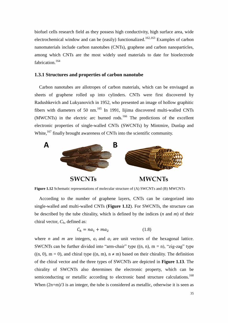
35
biofuel cells research field as they possess high conductivity, high surface area, wide
electrochemical window and can be (easily) functionalized.162,163
Examples of carbon
nanomaterials include carbon nanotubes (CNTs), graphene and carbon nanoparticles,
among which CNTs are the most widely used materials to date for bioelectrode
fabrication.164
1.3.1 Structures and properties of carbon nanotube
Carbon nanotubes are allotropes of carbon materials, which can be envisaged as
sheets of graphene rolled up into cylinders. CNTs were first discovered by
Radushkevich and Lukyanovich in 1952, who presented an image of hollow graphitic
fibers with diameters of 50 nm.165
In 1991, Iijima discovered multi-walled CNTs
(MWCNTs) in the electric arc burned rods.166
The predictions of the excellent
electronic properties of single-walled CNTs (SWCNTs) by Mintmire, Dunlap and
White,167
finally brought awareness of CNTs into the scientific community.
Figure 1.12 Schematic representations of molecular structure of (A) SWCNTs and (B) MWCNTs
According to the number of graphene layers, CNTs can be categorized into
single-walled and multi-walled CNTs (Figure 1.12). For SWCNTs, the structure can
be described by the tube chirality, which is defined by the indices (n and m) of their
chiral vector, Ch, defined as:
𝐶ℎ = 𝑛𝑎1 + 𝑚𝑎2 (1.8)
where n and m are integers, a1 and a1 are unit vectors of the hexagonal lattice.
SWCNTs can be further divided into “arm-chair” type ((n, n), m = n), “zig-zag” type
((n, 0), m = 0), and chiral type ((n, m), n ≠ m) based on their chirality. The definition
of the chiral vector and the three types of SWCNTs are depicted in Figure 1.13. The
chirality of SWCNTs also determines the electronic property, which can be
semiconducting or metallic according to electronic band structure calculations.168
When (2n+m)/3 is an integer, the tube is considered as metallic, otherwise it is seen as
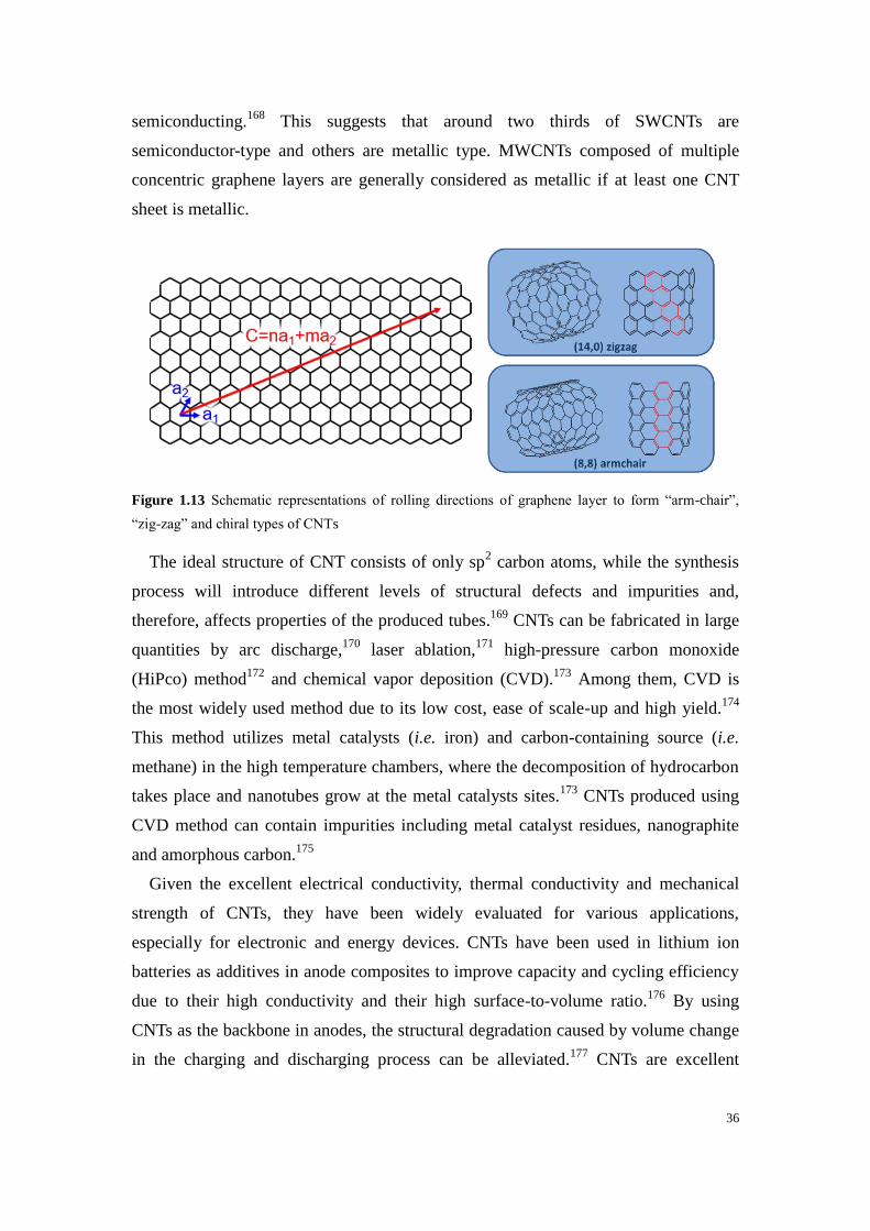
36
semiconducting.168
This suggests that around two thirds of SWCNTs are
semiconductor-type and others are metallic type. MWCNTs composed of multiple
concentric graphene layers are generally considered as metallic if at least one CNT
sheet is metallic.
Figure 1.13 Schematic representations of rolling directions of graphene layer to form “arm-chair”,
“zig-zag” and chiral types of CNTs
The ideal structure of CNT consists of only sp2 carbon atoms, while the synthesis
process will introduce different levels of structural defects and impurities and,
therefore, affects properties of the produced tubes.169
CNTs can be fabricated in large
quantities by arc discharge,170
laser ablation,171
high-pressure carbon monoxide
(HiPco) method172
and chemical vapor deposition (CVD).173
Among them, CVD is
the most widely used method due to its low cost, ease of scale-up and high yield.174
This method utilizes metal catalysts (i.e. iron) and carbon-containing source (i.e.
methane) in the high temperature chambers, where the decomposition of hydrocarbon
takes place and nanotubes grow at the metal catalysts sites.173
CNTs produced using
CVD method can contain impurities including metal catalyst residues, nanographite
and amorphous carbon.175
Given the excellent electrical conductivity, thermal conductivity and mechanical
strength of CNTs, they have been widely evaluated for various applications,
especially for electronic and energy devices. CNTs have been used in lithium ion
batteries as additives in anode composites to improve capacity and cycling efficiency
due to their high conductivity and their high surface-to-volume ratio.176
By using
CNTs as the backbone in anodes, the structural degradation caused by volume change
in the charging and discharging process can be alleviated.177
CNTs are excellent
37
electrode materials for electrochemical supercapacitor due to their high surface area,
resulting in high electrostatic double-layer capacitance.178
CNTs also find wide
applications in proton exchange membrane fuel cells mainly to reduce platinum
loading while maintaining the fuel cell efficiency.179
The unique features of CNTs are also beneficial for applications in
bioelectrochemistry. The entangled CNTs can form three-dimensional network with
high porosity to immobilize enzymes. More importantly, the thin diameter of CNTs
makes it possible to approach the active site of enzymes, therefore promoting direct
electron transfer.180
However, the hydrophobic nature of CNTs makes them insoluble
and they tend to aggregate in most solvents, resulting in more difficulty in handling.
Organic solvents or surfactants are required to make stable dispersion of CNTs for
practical applications.181
1.3.2 Modification and functionalization of carbon nanotubes
As previously described for enzyme immobilization, modifications of the electrode
surface are often required to introduce different functionalities to favor orientation and
immobilization of enzymes for applications, e.g. in bioelectrochemical devices.
Functionalization of CNTs has been intensively studied for the development of EFCs
in recent years.182,183
The functionalization methods of CNTs are divided into covalent
and non-covalent methods.
1.3.2.1 Covalent method
Covalent method is based on introduction of functional groups by creating stable
covalent bonds on the CNT surface, which simultaneously changes the hybridization
of carbon atoms from sp2 to sp
3. The generated functionalities can improve solubility
of CNTs and enable further coupling reactions. However, covalent method will
inevitably damage their π-conjugated system, which impacts the electronic and
mechanical properties of CNTs. In general, there are two approaches to covalently
modify CNTs: esterification or amidation of oxidized CNTs and addition chemistry of
CNTs.184
Oxidation treatment is a widely used method to generate oxygen-containing groups
such as carboxylic, carbonyl and hydroxyl groups along the sidewall or at the
pre-existing defect sites at the open ends of CNTs (Figure 1.14).185
Chemical
oxidation involves placing CNTs in oxidative mediums under reflux conditions with

38
acidic (sulfuric acid and nitric acid) or basic (ammonium hydroxide/hydrogen
peroxide) agents.186
There are many studies on investigating the effect of oxidation
conditions on the structure of CNTs.185–187
In brief, the degradation of the CNT
structure increases with the duration and hardness of the oxidation treatment.187
The
as-generated carboxylic groups can undergo further modification through
esterification or amidation (Figure 1.14).
Figure 1.14 Scheme of esterification or amidation (peptide coupling if R is an enzyme) of oxidized
CNTs
Another covalent method for functionalization of this carbon material is the use of
addition chemistry to attach organic moieties to the sidewall of CNTs. This method
contains diverse reactions such as cycloaddition,188
addition of carbenes189
and
nitrenes,190,191
radical additions,190,192
etc... Among them, the most investigated
reaction is the radical addition of phenyldiazonium (Figure 1.15). The popularity of
this reaction is related to its versatility and high functionalization degree.193
The
grafted phenyl groups can then be used to react with other molecules.
Figure 1.15 Modification of CNTs by radical addition of a diazonium salt preformed or formed in situ
1.3.2.2 Non-covalent method
Compared with covalent method, non-covalent method takes advantage of the sp2
carbon atoms on the sidewall of CNTs, which can facilitate strong interaction between
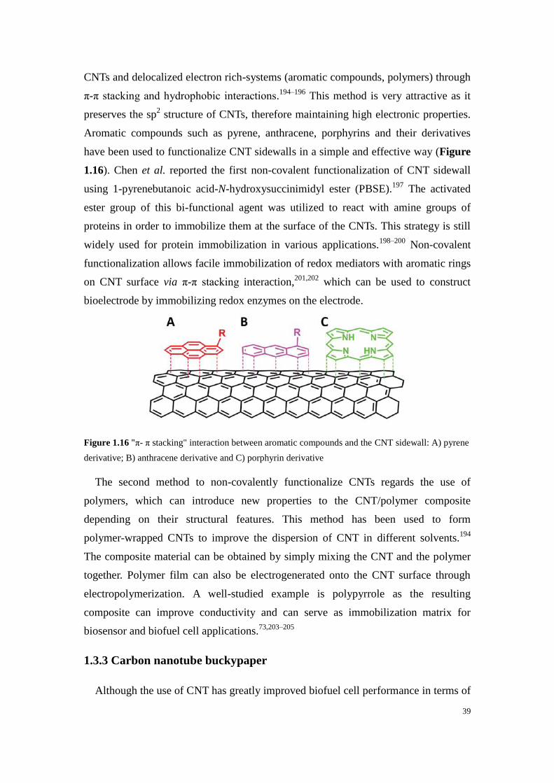
39
CNTs and delocalized electron rich-systems (aromatic compounds, polymers) through
π-π stacking and hydrophobic interactions.194–196
This method is very attractive as it
preserves the sp2 structure of CNTs, therefore maintaining high electronic properties.
Aromatic compounds such as pyrene, anthracene, porphyrins and their derivatives
have been used to functionalize CNT sidewalls in a simple and effective way (Figure
1.16). Chen et al. reported the first non-covalent functionalization of CNT sidewall
using 1-pyrenebutanoic acid-N-hydroxysuccinimidyl ester (PBSE).197
The activated
ester group of this bi-functional agent was utilized to react with amine groups of
proteins in order to immobilize them at the surface of the CNTs. This strategy is still
widely used for protein immobilization in various applications.198–200
Non-covalent
functionalization allows facile immobilization of redox mediators with aromatic rings
on CNT surface via π-π stacking interaction,201,202
which can be used to construct
bioelectrode by immobilizing redox enzymes on the electrode.
Figure 1.16 "π- π stacking" interaction between aromatic compounds and the CNT sidewall: A) pyrene
derivative; B) anthracene derivative and C) porphyrin derivative
The second method to non-covalently functionalize CNTs regards the use of
polymers, which can introduce new properties to the CNT/polymer composite
depending on their structural features. This method has been used to form
polymer-wrapped CNTs to improve the dispersion of CNT in different solvents.194
The composite material can be obtained by simply mixing the CNT and the polymer
together. Polymer film can also be electrogenerated onto the CNT surface through
electropolymerization. A well-studied example is polypyrrole as the resulting
composite can improve conductivity and can serve as immobilization matrix for
biosensor and biofuel cell applications.73,203–205
1.3.3 Carbon nanotube buckypaper
Although the use of CNT has greatly improved biofuel cell performance in terms of

40
power density, the difficulty of manipulating CNT has impeded the industrialization
and commercialization of CNT-based bioelectronics devices. In most studies,
bioelectrodes have been constructed by depositing CNTs on supporting substrates
such as glassy carbon electrode to form thin films of several μm. For practical
applications, efforts have been made to improve the manipulation of CNTs by shaping
them into different forms of self-supporting electrodes, such as yarns,206,207
pellets46
and papers.208
CNT pellet electrodes are obtained by mechanical compression of CNTs-based
slurry. Often, the CNTs are readily compressed in the presence of enzymes and other
components such as electron mediators to ensure efficient
distribution/homogenization of the redox species in the whole electrode volume.46
Most high power EFC reported to date are based on CNT pellet bioelectrodes.46,47,209
Although the three-dimensional pellet can host high number of enzymes and
mediators, the deeper volume of the pellet (as opposed to the interfacial layer with the
electrolyte) is hard to access due to inherent hydrophobicity of the tubes. Furthermore,
slow mass transfer across the volume (substrate consumption during electrocatalysis)
can lead to low volumetric power density.
In this thesis, a paper-like material called buckypaper is chosen as the material to
construct bioelectrodes. Buckypaper (BP) is a thin sheet made from entangled CNTs
held together by π-π interactions.210,211
For free-standing BP without the need of a
supporting material, the thickness should be at least over 80 μm.210
In 1998, Rinzler et
al. demonstrated the first so-called “buckypaper” made by vacuum filtration
method.208
BP was first fabricated as a way to manipulate SWCNTs, but has now been
used as promising materials in different applications such as supercapacitors,212
fuel
cells,213
sensors and biosensors,214,215
etc... BP is thin, lightweight, highly conductive
and easy to manipulate, which makes it a great candidate as the electrode material for
body interfaced bioelectronic devices. More importantly, BP is self-supporting,
therefore differentiates from other carbon nanostructured materials.
1.3.3.1 Fabrication of buckypaper
Given the attractive capabilities of BP, different methods have been developed for
the fabrication of BP. For example, CNT drawing, membrane filtration and casting
techniques are frequently found in literature reports.216,217
Buckypaper sheets are also
now commercially available from several manufacturers. Commercial buckypapers

41
from Buckeye Composite have been widely reported for the construction of
bioelectrodes.218–220
Buckypapers can also be obtained from US Research
Nanomaterials Inc.,221
NanoLab Inc.222
and Nanocomp Technologies Inc..223,224
However, the fabrication method of commercial buckypaper remains undisclosed and
these materials can display very different physical properties depending on the
manufacturers.
In laboratories, buckypapers are mostly fabricated using membrane filtration
technique, which is straightforward and can be easily set up. CNTs are first dispersed
in non-aqueous solvents such as N,N-dimethylformamide (DMF) and
N-methyl-2-pyrrolidinone (NMP), followed by sonication to form stable and
homogeneous suspension.225
Subsequently, the suspension is filtered through a
microporous membrane under negative pressure. After removal of the residual solvent
by a drying process, a self-supporting buckypaper can be obtained by carefully
peeling the CNTs film from the membrane. Although this method is simple and
widely used in research, there are challenges in the quality and reproducibility of
buckypapers. There are many factors that can affect the formation of buckypaper
including the suspension homogeneity, sonication procedure, type and length of CNT,
functionality and purity of the CNTs and the following treatments after filtration.216,226
An advantage of using membrane filtration method is the possibility to include a
wide range of molecules to the suspension to prepare functionalized buckypaper. For
example, buckypaper made from pristine CNTs is fragile and typically requires
reinforcement, which can be realized through the addition of a polymer227,228
or
pyrene-derivatives.106
The pyrene moieties of the modifiers can form strong
interaction with the CNTs and therefore improve cross-linking of CNTs.
1.3.4 Buckypaper-based biofuel cell
In 2011, Hussein et al. demonstrated the first results of buckypaper as electrode
material for enzymatic fuel cells.180,210,229
A buckypaper biocathode was fabricated by
immobilizing MvBOx and ABTS onto BP films, achieving a current density of 0.235
mA cm-2
in air-saturated buffer solution.210
The authors compared the oxygen
reduction performance of BP electrodes prepared from as-received CNTs and
acid-treated CNTs. In contrast, the BP electrode made from acid-treated CNTs showed
a 1.5-fold higher electrocatalytic current, which were attributed to more hydrophilic

42
electrode surface.210
The same group later developed a laccase-modified biocathode
with a catalytic current of 0.422 mA cm-2
, indicating the feasibility of using BP as
favorable electrode material for enzyme immobilization.180
Narváez Villarrubia et al. demonstrated the first buckypaper bioanode for L-malate
oxidation using a porcine NAD-dependent malate dehydrogenase (NAD-MDH).230
The BP was fabricated via filtration method with SWCNTs and was then modified
with poly methylene green (PMG) by electropolymerization. With the enzyme and the
cofactor NAD+
in solution, the bioanode shows a current density of 22 μA cm-2
in the
presence of 160 mmol L-1
L-malate.
Buckypaper based enzymatic fuel cell was first reported by Halámková et al. in
2012.218
The described glucose/O2 EFC consisted of a PQQ-GDH bioanode and a
Trametes versicolor laccase (TvLac) biocathode. Both electrodes were fabricated
using commercial buckypaper (Buckeye Composites). The EFCs was implanted in a
living snail.218
An OCV of 0.53 V and a power density of 30 μW cm-2
were obtained.
This is the first demonstration of BP-based fuel cell implanted in a living creature.
Later the same group reported implantable EFCs operating in clams,231
rats,232
lobsters233
and oranges.234
Reid et al. prepared a lactate biofuel cell integrated on contact lens using
commercial buckypaper, demonstrating the flexibility of this material.235
The biofuel
cell with a NAD-dependent lactate dehydrogenase (NAD-LDH) bioanode and a
MvBOx biocathode was tested in synthetic tear solution (~ 3 mmol L-1
lactate) and
delivered an OCV of 0.41 V and a power density of 8 μW cm-2
. The state-of-art
characteristics and performances of buckypaper based enzymatic fuel cells are
summarized in Table 1.4.
Nowadays the development of EFCs is progressing towards flexible, stretchable
and miniaturized electrodes for practical applications.19
The representative
applications of EFCs are described in the following section.
Table 1.4 Characteristics and performances of buckypaper-based enzymatic biofuel cell
Year Buckypapeper Anodic
enzyme
Cathodic
enzyme Substrate
OCV
/ V
Power
/ μW cm-2
Reference
2012 Commercial
BP
PQQ-GDH
(DET)
TvLac
(DET) Glucose, O2 (snail) 0.53 30
Halámková
et al.218

43
2013 Commercial
BP
PQQ-GDH
(DET)
TvLac
(DET) Glucose, O2 (lobster) 0.54 640
MacVittie
et al.233
2014 Lab-made
BP
GOx
(MET)
MvBOx
(DET)
5 mmol L-1
glucose,
O2 (air-saturated) 0.55 26
Bunte et
al.236
2014 Commercial
BP
PQQ-GDH
(DET)
MvBOx
(DET)
10 mmol L-1
glucose,
O2 (air-saturated) 0.7 107
Scherbahn
et al.237
2014 Commercial
BP
NAD-GDH
(MET)
MvBOx
(DET)
Mono/disaccharides
O2
1.8
(3 in
series)
0.18
(mW mg-1
GDH)
Narváez
Villarrubia
et al.238
2015 Commercial
BP
NAD-LDH
(MET)
MvBOx
(DET)
3 mmol L-1
lactate,
O2 (tear) 0.41 8 Reid et al.
235
2016 Commercial
BP
PQQ-GDH
(DET)
MvBOx
(DET)
Glucose, O2 (urine) 0.4 13 Göbel et
al.220
Glucose, O2 (saliva) 0.67 19
2016 Commercial
BP
NAD-GDH
(MET)
MvBOx
(DET)
100 mmol L-1
glucose,,
O2 0.59 1070
Narváez
Villarrubia
et al.239
2017 Lab-made
BP
FAD-GDH
(MET)
TvLac
(DET)
30 mmol L-1
glucose,
O2-saturated
1.4
(2 in
series)
326 Hou and
Liu240
2019 Commercial
BP
PQQ-GDH
(DET)
MvBOx
(DET) Glucose, O2 (slug) 0.31
200
μW cm-3
Bollella et
al.241
1.4 Applications of enzymatic fuel cells
1.4.1 Implantable glucose/O2 biofuel cells
Since the development of enzymatic biofuel cells, one of the most promising
applications of EFCs is to replace lithium batteries as power sources for implantable
electronic devices. These lithium batteries pose safety concerns to human body and
requires complex surgery for replacement.242,243
Glucose/O2 EFCs instead are energy
conversion devices that can harvest energy directly from the human body due to the
constant occurrence of “fuels” in body fluids. However, the power performance of
EFCs is limited by the low concentration of glucose (~ 5.5 mmol L-1
in blood44
) and
oxygen (~ 90 µmol L-1
in plasma,244
~ 50 µmol L-1
in cerebrospinal fluid245
) in human

44
physiological fluids.
The first successful in vivo demonstration of implantable enzymatic biofuel cell
was operated in a grape, which was developed by Mano and Heller.246
In this work,
both bioanode and biocathode were electrically wired by osmium redox polymer.
Miyake247
and Yoshino248
also reported several implantable biofuel cells operated in
grapes and showed improved power density by using ketjen black and CNTs as
electrode materials, respectively.
A major breakthrough in this field is the successful implantation of EFCs in rats.249
Compared with previous work in living plants, implantation in animals are much
more difficult. On one hand, the electrical connection needs to be robust enough to
withstand the strain caused by the movement of the animals. On the other hand,
biocompatible packaging of the device is required to avoid inflammatory responses.
The collaborative work of Cosnier and Cinquin demonstrated the first implantable
EFC operated in a living mammal. The device composed of a GOx bioanode and a
polyphenol oxidase (PPO) biocathode was placed in the retroperitoneal space of the
rat.249
Followed by this pioneer work, various implanted devices have been reported
(Table 1.5). It is worth noting that to date most EFCs are developed based on CNT
nanostructured materials to improve power performance.
With the emerging of ultra-lower power consumption electronic devices and
nanomaterial-based EFCs, glucose/O2 EFCs remain attractive as energy harvesters.
Another challenge in this field is the device lifetime, which should be longer than
current commercial batteries used for implantable medical devices (IMDs). For
example, the lithium iodide cells used for pacemaker usually lasts 7-8 years.250
The
state-of-art power and lifetime of the reported implantable glucose/O2 EFCs are
summarized in Table 1.5. The current lifetime is still far below the requirement for
IMD application. For successful implantation of EFCs, intensive studies are also
required to understand and improve the biocompatibility of bioelectrodes. This
includes factors such as cytotoxicity, carcinogenicity, genotoxicity, irritation and
sensitization, etc.251
Table 1.5 Characteristics and performances of implantable glucose/O2 enzymatic biofuel cells
Year Organism Electrode
material
Anodic
enzyme
Cathodic
enzyme
Power
/ μW cm-2
Stability Reference

45
2003 Grape Carbon fiber GOx
(MET)
BOx
(MET) 430
1 week
(in buffer)119
Mano et al.
246
2010 Rat Graphite GOx
(MET)
PPO
(MET) 1.5 11 days
Cinquin
et al.249
2011 Rabbit ear Ketjen
black
GDH
(MET)
BOx
(DET) 1310 /
Miyake
et al.247
2012 Cockroach Carbon rod TOx
[a]|GOx
(MET)
BOx
(MET) 55 2.5 hours
Rasmussen
et al.252
2013 Grape CNT forest GOx
(MET)
BOx
(DET) 1750 /
Yoshino
et al.248
2013 Rat CNT
Pellet
GOx
(DET)
Lac
(DET) 193 9 days Zebda et al.
253
2013 Rat Commercial
BP
PQQ-GDH
(DET)
Lac
(DET) 0.17 /
Castorena-
Gonzalez
et al.232
2013 Lobster Commercial
BP
PQQ-GDH
(DET)
Lac
(DET) 640 /
MacVittie
et al.233
2013 Rat Au microwire CDH
(DET)
BOx
(DET) 2
Several
hours
Andoralov et
al.254
2018 Rabbit CNT
Pellet
GOx
(MET)
Lac
(DET)
16
μW cm-3
2 months
El
Ichi-Ribault et
al.255
2019 Slug Commercial
BP
PQQ-GDH
(DET)
BOx
(DET)
200
μW cm-3
/
Bollella et
al.241
[a] Trehalase oxidase
1.4.2 Wearable lactate/O2 biofuel cells
Wearable electronics has recently drawn significant attention especially wearable
biomedical devices for health and fitness monitoring.256
Since most wearable devices
are skin-worn, the device should be small, flexible, robust and do not pose any burden
to the wearer. One of the key challenges in this field is to develop a power source that
is equally flexible and robust to meet the requirements of wearable devices.
Epidermal lactate/O2 EFCs are attractive candidates as they can harvest energy
46
directly from sweat. Human sweat contains several metabolites such as glucose,
alcohol, lactate and cortisol.257
Among them, lactate is exploited as the biofuel due to
its high concentration in sweat, with an average level of 14 mmol L-1 in sweat.
257
The first successful demonstration of wearable sweat-based enzymatic biofuel cell
was developed by Jia et al. in 2013.135
In this work, screen printing technology was
used to fabricate electrode on the tattoo paper using CNT ink. The anode and cathode
were modified with lactate oxidase and platinum black, respectively. This work
demonstrates the first prototype device that can harvest energy from on-body
experiments. Later, the same group developed a textile-based biofuel cell by
screen-printing the biofuel cell onto detachable care label.258
Obviously, textile-based
biofuel cells enable large area of device integration and different combinations to
increase voltage and power. Besides sweat, lactate in tears has also been exploited as
fuels by integration of a biofuel cell onto contact lens.235
Although lactate based biofuel cells show promise as power sources for wearable
electronics, multiple issues need to be addressed for further development. The biggest
challenge is the limited power density due to the low catalytic performance of the
bioanode. Intensive studies are necessary to develop a more efficient mediator for
lactate oxidase. Secondly, current devices are not able to deliver stable power output
due to factors such as fluctuations of lactate level and inhibitors present in sweat.
Similar to implantable EFCs, lifetime and biocompatibility are also major challenges
that limit the use of wearable lactate enzymatic fuel cell.
1.4.3 Biosupercapacitor
Enzymatic fuel cell is an attractive energy conversion device with an inherent issue
of low power density. In contrast, supercapacitor is an energy storage device that can
deliver high power pulses. A new hybrid device called “self-charging electrochemical
biocapacitor” has been proposed by Pankratov et al. to construct hybrid device that
contains an enzymatic fuel cell and an electrochemical capacitor.259
The principle is to
release power by high-current pulse discharge while the capacitor self-charges
through enzymatic conversion of the substrate. The device developed by Pankratov et
al. in 2014 was based on dual-feature electrodes. One side of the graphite electrode
was modified with polyaniline for pseudocapacitance while the other side was
immobilized with enzyme for biocatalytic reaction. Upon pulse discharge, the device
47
reached a power density of 1.2 mW cm-2
at 0.38 V. In principle, most EFCs can also
work as self-charging electrochemical biocapacitor without modification. Agnès et al.
reported the first supercapacitor/biofuel cell hybrid device based on double layer
capacitance.260
This new concept shows promises to overcome the low power density
issues in traditional enzymatic biofuel cells.

48
References
1. Jaouen, F., Lefèvre, M., Dodelet, J.-P. & Cai, M. Heat-Treated Fe/N/C Catalysts for O2
Electroreduction: Are Active Sites Hosted in Micropores? J. Phys. Chem. B 110, 5553–5558
(2006).
2. Stariha, S. et al. PGM-free Fe-N-C catalysts for oxygen reduction reaction: Catalyst layer design.
Journal of Power Sources 326, 43–49 (2016).
3. Wachsman, E. D. & Lee, K. T. Lowering the Temperature of Solid Oxide Fuel Cells. Science 334,
935–939 (2011).
4. Logan, B. E. et al. Microbial Fuel Cells: Methodology and Technology. Environ. Sci. Technol.
40, 5181–5192 (2006).
5. Logan, B. E. & Regan, J. M. Microbial Fuel Cells—Challenges and Applications. Environ. Sci.
Technol. 40, 5172–5180 (2006).
6. Bhatnagar, D., Xu, S., Fischer, C., L. Arechederra, R. & D. Minteer, S. Mitochondrial biofuel
cells : expanding fuel diversity to amino acids. Physical Chemistry Chemical Physics 13, 86–92
(2011).
7. Rasmussen, M., Abdellaoui, S. & Minteer, S. D. Enzymatic biofuel cells: 30 years of critical
advancements. Biosensors and Bioelectronics 76, 91–102 (2016).
8. Gil, G.-C. et al. Operational parameters affecting the performannce of a mediator-less microbial
fuel cell. Biosensors and Bioelectronics 18, 327–334 (2003).
9. Heijne, A. T. et al. Identifying charge and mass transfer resistances of an oxygen reducing
biocathode. Energy & Environmental Science 4, 5035–5043 (2011).
10. Bergel, A., Féron, D. & Mollica, A. Catalysis of oxygen reduction in PEM fuel cell by seawater
biofilm. Electrochemistry Communications 7, 900–904 (2005).
11. Rabaey, K. et al. Cathodic oxygen reduction catalyzed by bacteria in microbial fuel cells. ISME J
2, 519–527 (2008).
12. Pant, D. et al. An introduction to the life cycle assessment (LCA) of bioelectrochemical systems
(BES) for sustainable energy and product generation: Relevance and key aspects. Renewable and
Sustainable Energy Reviews 15, 1305–1313 (2011).
13. Logan, B. E. & Rabaey, K. Conversion of Wastes into Bioelectricity and Chemicals by Using
Microbial Electrochemical Technologies. Science 337, 686–690 (2012).
14. Rozendal, R. A., Hamelers, H. V. M., Rabaey, K., Keller, J. & Buisman, C. J. N. Towards
practical implementation of bioelectrochemical wastewater treatment. Trends in Biotechnology
26, 450–459 (2008).
15. Ieropoulos, I., Greenman, J. & Melhuish, C. Urine utilisation by microbial fuel cells; energy fuel
for the future. Physical Chemistry Chemical Physics 14, 94–98 (2012).
16. Andrea Ieropoulos, I. et al. Pee power urinal – microbial fuel cell technology field trials in the
context of sanitation. Environmental Science: Water Research & Technology 2, 336–343 (2016).
17. Yahiro, A. T., Lee, S. M. & Kimble, D. O. Bioelectrochemistry: I. Enzyme utilizing bio-fuel cell
studies. Biochimica et Biophysica Acta (BBA) - Specialized Section on Biophysical Subjects 88,
375–383 (1964).
49
18. Xiao, X. et al. Tackling the Challenges of Enzymatic (Bio)Fuel Cells. Chem. Rev. (2019)
doi:10.1021/acs.chemrev.9b00115.
19. Luz, R. A. S., Pereira, A. R., de Souza, J. C. P., Sales, F. C. P. F. & Crespilho, F. N. Enzyme
Biofuel Cells: Thermodynamics, Kinetics and Challenges in Applicability.
CHEMELECTROCHEM 1, 1751–1777 (2014).
20. Truesdale, G. A. & Downing, A. L. Solubility of Oxygen in Water. Nature 173, 1236–1236
(1954).
21. Arechederra, R. & Minteer, S. D. Organelle-based biofuel cells: Immobilized mitochondria on
carbon paper electrodes. Electrochimica Acta 53, 6698–6703 (2008).
22. Arechederra, R. L., Boehm, K. & Minteer, S. D. Mitochondrial bioelectrocatalysis for biofuel
cell applications. Electrochimica Acta 54, 7268–7273 (2009).
23. Germain, M. N., Arechederra, R. L. & Minteer, S. D. Nitroaromatic Actuation of Mitochondrial
Bioelectrocatalysis for Self-Powered Explosive Sensors. J. Am. Chem. Soc. 130, 15272–15273
(2008).
24. L. Maltzman, S. & D. Minteer, S. Mitochondrial-based voltammetric sensor for pesticides.
Analytical Methods 4, 1202–1206 (2012).
25. De Michele, R., Carimi, F. & Frommer, W. B. Mitochondrial biosensors. The International
Journal of Biochemistry & Cell Biology 48, 39–44 (2014).
26. Masa, J. & Schuhmann, W. Electrocatalysis and bioelectrocatalysis – Distinction without a
difference. Nano Energy 29, 466–475 (2016).
27. Marchitti, S. A., Brocker, C., Stagos, D. & Vasiliou, V. Non-P450 aldehyde oxidizing enzymes:
the aldehyde dehydrogenase superfamily. Expert Opinion on Drug Metabolism & Toxicology 4,
697–720 (2008).
28. Ludwig, R., Harreither, W., Tasca, F. & Gorton, L. Cellobiose Dehydrogenase: A Versatile
Catalyst for Electrochemical Applications. ChemPhysChem 11, 2674–2697 (2010).
29. Theorell, H. & McKEE, J. S. M. Mechanism of Action of Liver Alcohol Dehydrogenase. Nature
192, 47–50 (1961).
30. Ferry, J. G. Formate dehydrogenase. FEMS Microbiol Rev 7, 377–382 (1990).
31. Adachi, T., Kaida, Y., Kitazumi, Y., Shirai, O. & Kano, K. Bioelectrocatalytic performance of
d-fructose dehydrogenase. Bioelectrochemistry 129, 1–9 (2019).
32. Ferri, S., Kojima, K. & Sode, K. Review of Glucose Oxidases and Glucose Dehydrogenases: A
Bird’s Eye View of Glucose Sensing Enzymes. J Diabetes Sci Technol 5, 1068–1076 (2011).
33. Maeda-Yorita, K., Aki, K., Sagai, H., Misaki, H. & Massey, V. L-lactate oxidase and L-lactate
monooxygenase: Mechanistic variations on a common structural theme. Biochimie 77, 631–642
(1995).
34. Holbrook, J. J., Liljas, A., Steindel, S. J. & Rossmann, M. G. 4 Lactate Dehydrogenase. in The
Enzymes (ed. Boyer, P. D.) vol. 11 191–292 (Academic Press, 1975).
35. Adams, M. W. W., Mortenson, L. E. & Chen, J.-S. Hydrogenase. Biochimica et Biophysica Acta
(BBA) - Reviews on Bioenergetics 594, 105–176 (1980).
36. Cosnier, S., J. Gross, A., Le Goff, A. & Holzinger, M. Recent advances on enzymatic
glucose/oxygen and hydrogen/oxygen biofuel cells: Achievements and limitations. Journal of

50
Power Sources 325, 252–263 (2016).
37. de Poulpiquet, A., Ranava, D., Monsalve, K., Giudici‐Orticoni, M.-T. & Lojou, E. Biohydrogen
for a New Generation of H2/O2 Biofuel Cells: A Sustainable Energy Perspective.
ChemElectroChem 1, 1724–1750 (2014).
38. Frey, M. Hydrogenases: Hydrogen-Activating Enzymes. ChemBioChem 3, 153–160 (2002).
39. K. Jones, A., Sillery, E., J. Albracht, S. P. & A. Armstrong, F. Direct comparison of the
electrocatalytic oxidation of hydrogen by an enzyme and a platinum catalyst. Chemical
Communications 0, 866–867 (2002).
40. De Lacey, A. L., Fernández, V. M., Rousset, M. & Cammack, R. Activation and Inactivation of
Hydrogenase Function and the Catalytic Cycle: Spectroelectrochemical Studies. Chem. Rev. 107,
4304–4330 (2007).
41. Wait, A. F., Parkin, A., Morley, G. M., dos Santos, L. & Armstrong, F. A. Characteristics of
Enzyme-Based Hydrogen Fuel Cells Using an Oxygen-Tolerant Hydrogenase as the Anodic
Catalyst. J. Phys. Chem. C 114, 12003–12009 (2010).
42. Cracknell, J. A., Wait, A. F., Lenz, O., Friedrich, B. & Armstrong, F. A. A kinetic and
thermodynamic understanding of O2 tolerance in [NiFe]-hydrogenases. PNAS 106, 20681–
20686 (2009).
43. Plumeré, N. et al. A redox hydrogel protects hydrogenase from high-potential deactivation and
oxygen damage. Nature Chemistry 6, 822–827 (2014).
44. Danaei, G. et al. National, regional, and global trends in fasting plasma glucose and diabetes
prevalence since 1980: systematic analysis of health examination surveys and epidemiological
studies with 370 country-years and 2·7 million participants. The Lancet 378, 31–40 (2011).
45. Gregg, B. A. & Heller, Adam. Cross-linked redox gels containing glucose oxidase for
amperometric biosensor applications. Analytical Chemistry 62, 258–263 (1990).
46. Zebda, A. et al. Mediatorless high-power glucose biofuel cells based on compressed carbon
nanotube-enzyme electrodes. Nature Communications 2, 370 (2011).
47. Reuillard, B. et al. High power enzymatic biofuel cell based on naphthoquinone-mediated
oxidation of glucose by glucose oxidase in a carbon nanotube 3D matrix. Physical Chemistry
Chemical Physics 15, 4892 (2013).
48. D. Milton, R., Giroud, F., E. Thumser, A., D. Minteer, S. & T. Slade, R. C. Hydrogen peroxide
produced by glucose oxidase affects the performance of laccase cathodes in glucose/oxygen fuel
cells: FAD-dependent glucose dehydrogenase as a replacement. Physical Chemistry Chemical
Physics 15, 19371–19379 (2013).
49. Clark, W. M. (William M. & 1884-1964. Oxidation-reduction potentials of organic systems.
(1960).
50. Karyakin, A. A., Karyakina, E. E. & Schmidt, H.-L. Electropolymerized Azines: A New Group of
Electroactive Polymers. Electroanalysis 11, 149–155 (1999).
51. Le Goff, A., Holzinger, M. & Cosnier, S. Recent progress in oxygen-reducing laccase
biocathodes for enzymatic biofuel cells. Cellular and Molecular Life Sciences 72, 941–952
(2015).
52. Mano, N. & Edembe, L. Bilirubin oxidases in bioelectrochemistry: Features and recent findings.

51
Biosensors and Bioelectronics 50, 478–485 (2013).
53. Solomon, E. I. et al. Copper Active Sites in Biology. Chem. Rev. 114, 3659–3853 (2014).
54. Miura, Y. et al. Direct Electrochemistry of CueO and Its Mutants at Residues to and Near Type I
Cu for Oxygen-Reducing Biocathode. Fuel Cells 9, 70–78 (2009).
55. Reuillard, B. et al. Direct electron transfer between tyrosinase and multi-walled carbon
nanotubes for bioelectrocatalytic oxygen reduction. Electrochemistry Communications 20, 19–22
(2012).
56. Katz, E., Lioubashevski, O. & Willner, I. Magnetic Field Effects on Bioelectrocatalytic
Reactions of Surface-Confined Enzyme Systems: Enhanced Performance of Biofuel Cells. J. Am.
Chem. Soc. 127, 3979–3988 (2005).
57. Heering, H. A. Analysis of protein film voltammograms as Michaelis–Menten saturation curves
yield the electron cooperativity number for deconvolution. Bioelectrochemistry 87, 58–64
(2012).
58. Elouarzaki, K. et al. Freestanding HRP–GOx redox buckypaper as an oxygen-reducing
biocathode for biofuel cell applications. Energy Environ. Sci. 8, 2069–2074 (2015).
59. Tarasevich, M. R., Yaropolov, A. I., Bogdanovskaya, V. A. & Varfolomeev, S. D. 293 -
Electrocatalysis of a cathodic oxygen reduction by laccase. Bioelectrochemistry and
Bioenergetics 6, 393–403 (1979).
60. Tsujimura, S. et al. Bioelectrocatalytic reduction of dioxygen to water at neutral pH using
bilirubin oxidase as an enzyme and 2,2′-azinobis (3-ethylbenzothiazolin-6-sulfonate) as an
electron transfer mediator. Journal of Electroanalytical Chemistry 496, 69–75 (2001).
61. Palmore, G. T. R. Biofuel Cells. in Bioelectrochemistry 359–375 (John Wiley & Sons, Ltd, 2008).
doi:10.1002/9780470753842.ch10.
62. Bard, A. J. & Faulkner, L. R. Electrochemical methods: fundamentals and applications. (Wiley,
2001).
63. LAVIRON, E. GENERAL EXPRESSION OF THE LINEAR POTENTIAL SWEEP
VOLTAMMOGRAM IN THE CASE OF DIFFUSIONLESS ELECTROCHEMICAL
SYSTEMS. 10.
64. Enzyme Stabilization and Immobilization. vol. 1504 (Springer New York, 2017).
65. Armstrong, F. A. & Wilson, G. S. Recent developments in faradaic bioelectrochemistry.
Electrochimica Acta 45, 2623–2645 (2000).
66. Kowalewska, B. & Jakubow, K. The impact of immobilization process on the electrochemical
performance, bioactivity and conformation of glucose oxidase enzyme. Sensors and Actuators B:
Chemical 238, 852–861 (2017).
67. Alonso-Lomillo, M. A., Yardimci, C., Domínguez-Renedo, O. & Arcos-Martínez, M. J. CYP450
2B4 covalently attached to carbon and gold screen printed electrodes by diazonium salt and
thiols monolayers. Analytica Chimica Acta 633, 51–56 (2009).
68. Gao, Y. & Kyratzis, I. Covalent Immobilization of Proteins on Carbon Nanotubes Using the
Cross-Linker 1-Ethyl-3-(3-dimethylaminopropyl)carbodiimide—a Critical Assessment.
Bioconjugate Chem. 19, 1945–1950 (2008).
69. Rusmini, F., Zhong, Z. & Feijen, J. Protein Immobilization Strategies for Protein Biochips.
52
Biomacromolecules 8, 1775–1789 (2007).
70. Mateo, C., Fernández-Lorente, G., Abian, O., Fernández-Lafuente, R. & Guisán, J. M.
Multifunctional Epoxy Supports: A New Tool To Improve the Covalent Immobilization of
Proteins. The Promotion of Physical Adsorptions of Proteins on the Supports before Their
Covalent Linkage. Biomacromolecules 1, 739–745 (2000).
71. Al‐Lolage, F. A., Meneghello, M., Ma, S., Ludwig, R. & Bartlett, P. N. A Flexible Method for the
Stable, Covalent Immobilization of Enzymes at Electrode Surfaces. ChemElectroChem 4, 1528–
1534 (2017).
72. Soellner, M. B., Dickson, K. A., Nilsson, B. L. & Raines, R. T. Site-Specific Protein
Immobilization by Staudinger Ligation. J. Am. Chem. Soc. 125, 11790–11791 (2003).
73. Ionescu, R. E., Abu-Rabeah, K., Cosnier, S. & Marks, R. S. Improved enzyme retention from an
electropolymerized polypyrrole-alginate matrix in the development of biosensors.
Electrochemistry Communications 7, 1277–1282 (2005).
74. Ichi, S. E. et al. Chitosan improves stability of carbon nanotube biocathodes for glucose biofuel
cells. Chem. Commun. 50, 14535–14538 (2014).
75. Moore, C. M., Akers, N. L., Hill, A. D., Johnson, Z. C. & Minteer, S. D. Improving the
Environment for Immobilized Dehydrogenase Enzymes by Modifying Nafion with
Tetraalkylammonium Bromides. Biomacromolecules 5, 1241–1247 (2004).
76. Li, J., Tan, S. N. & Ge, H. Silica sol-gel immobilized amperometric biosensor for hydrogen
peroxide. Analytica Chimica Acta 335, 137–145 (1996).
77. Ohara, T. J., Rajagopalan, Ravi. & Heller, Adam. Glucose electrodes based on cross-linked
bis(2,2’-bipyridine)chloroosmium(+/2+) complexed poly(1-vinylimidazole) films. Analytical
Chemistry 65, 3512–3517 (1993).
78. Tsujimura, S., Murata, K. & Akatsuka, W. Exceptionally High Glucose Current on a
Hierarchically Structured Porous Carbon Electrode with ‘Wired’ Flavin Adenine
Dinucleotide-Dependent Glucose Dehydrogenase. J. Am. Chem. Soc. 136, 14432–14437 (2014).
79. Bucur, B., Danet, A. F. & Marty, J.-L. Versatile method of cholinesterase immobilisation via
affinity bonds using Concanavalin A applied to the construction of a screen-printed biosensor.
Biosensors and Bioelectronics 20, 217–225 (2004).
80. Esseghaier, C. et al. Impedance spectroscopy on immobilized streptavidin horseradish
peroxidase layer for biosensing. Sensors and Actuators B: Chemical 134, 112–116 (2008).
81. Holzinger, M., Bouffier, L., Villalonga, R. & Cosnier, S. Adamantane/β-cyclodextrin affinity
biosensors based on single-walled carbon nanotubes. Biosensors and Bioelectronics 24, 1128–
1134 (2009).
82. Halliwell, C. M., Simon, E., Toh, C.-S., Bartlett, P. N. & Cass, A. E. G. Immobilisation of lactate
dehydrogenase on poly(aniline)–poly(acrylate) and poly(aniline)–poly(vinyl sulphonate) films
for use in a lactate biosensor. Analytica Chimica Acta 453, 191–200 (2002).
83. Marcus, R. A. & Sutin, N. Electron transfers in chemistry and biology. Biochimica et Biophysica
Acta (BBA) - Reviews on Bioenergetics 811, 265–322 (1985).
84. Page, C. C., Moser, C. C., Chen, X. & Dutton, P. L. Natural engineering principles of electron
tunnelling in biological oxidation–reduction. Nature 402, 47–52 (1999).

53
85. Turner, A., Karube, I. & Wilson, G. S. Biosensors : Fundamentals and Applications. (Oxford
University Press, 1987).
86. Updike, S. J. & Hicks, G. P. The Enzyme Electrode. Nature 214, 986–988 (1967).
87. Guilbault, G. G. & Lubrano, G. J. An enzyme electrode for the amperometric determination of
glucose. Analytica Chimica Acta 64, 439–455 (1973).
88. Chaubey, A. & Malhotra, B. D. Mediated biosensors. Biosensors and Bioelectronics 17, 441–456
(2002).
89. Heller, A. Electrical wiring of redox enzymes. Acc. Chem. Res. 23, 128–134 (1990).
90. Heller, A. Electrical connection of enzyme redox centers to electrodes. J. Phys. Chem. 96, 3579–
3587 (1992).
91. Guschin, D. A., Castillo, J., Dimcheva, N. & Schuhmann, W. Redox electrodeposition polymers:
adaptation of the redox potential of polymer-bound Os complexes for bioanalytical applications.
Anal Bioanal Chem 398, 1661–1673 (2010).
92. Pinyou, P. et al. Design of an Os Complex-Modified Hydrogel with Optimized Redox Potential
for Biosensors and Biofuel Cells. Chemistry – A European Journal 22, 5319–5326 (2016).
93. Knoche, K. L., Hickey, D. P., Milton, R. D., Curchoe, C. L. & Minteer, S. D. Hybrid Glucose/O 2
Biobattery and Supercapacitor Utilizing a Pseudocapacitive Dimethylferrocene Redox Polymer
at the Bioanode. ACS Energy Letters 1, 380–385 (2016).
94. Tapia, C. et al. Wiring of Photosystem I and Hydrogenase on an Electrode for
Photoelectrochemical H2 Production by using Redox Polymers for Relatively Positive Onset
Potential. ChemElectroChem 4, 90–95 (2017).
95. Eng, L. H. et al. Viologen-Based Redox Polymer for Contacting the Low-Potential Redox
Enzyme Hydrogenase at an Electrode Surface. J. Phys. Chem. 98, 7068–7072 (1994).
96. Sokol, K. P. et al. Rational wiring of photosystem II to hierarchical indium tin oxide electrodes
using redox polymers. Energy Environ. Sci. 9, 3698–3709 (2016).
97. Milton, R. D. et al. Rational design of quinones for high power density biofuel cells. Chem. Sci.
6, 4867–4875 (2015).
98. J. Eddowes, M. & O. Hill, H. A. Novel method for the investigation of the electrochemistry of
metalloproteins: cytochrome c. Journal of the Chemical Society, Chemical Communications 0,
771b–7772 (1977).
99. Yeh, P. & Kuwana, T. Reversible electrode reaction of cytochrome c. Chem. Lett. 6, 1145–1148
(1977).
100. Murata, K., Suzuki, M., Kajiya, K., Nakamura, N. & Ohno, H. High performance bioanode
based on direct electron transfer of fructose dehydrogenase at gold nanoparticle-modified
electrodes. Electrochemistry Communications 11, 668–671 (2009).
101. Tasca, F., Harreither, W., Ludwig, R., Gooding, J. J. & Gorton, L. Cellobiose Dehydrogenase
Aryl Diazonium Modified Single Walled Carbon Nanotubes: Enhanced Direct Electron Transfer
through a Positively Charged Surface. Anal. Chem. 83, 3042–3049 (2011).
102. Kizling, M. & Bilewicz, R. Fructose Dehydrogenase Electron Transfer Pathway in
Bioelectrocatalytic Reactions. ChemElectroChem 5, 166–174 (2018).
103. Blanford, C. F., Heath, R. S. & Armstrong, F. A. A stable electrode for high-potential,

54
electrocatalytic O2 reduction based on rational attachment of a blue copper oxidase to a graphite
surface. Chem. Commun. 1710–1712 (2007) doi:10.1039/B703114A.
104. Gorton, L. et al. Direct electron transfer between heme-containing enzymes and electrodes as
basis for third generation biosensors. Analytica Chimica Acta 400, 91–108 (1999).
105. Rubenwolf, S., Kerzenmacher, S., Zengerle, R. & von Stetten, F. Strategies to extend the lifetime
of bioelectrochemical enzyme electrodes for biosensing and biofuel cell applications. Appl
Microbiol Biotechnol 89, 1315–1322 (2011).
106. Bourourou, M. et al. Freestanding redox buckypaper electrodes from multi-wall carbon
nanotubes for bioelectrocatalytic oxygen reduction via mediated electron transfer. Chemical
Science 5, 2885 (2014).
107. Zhu, Z. & Zhang, Y.-H. P. Use of nonimmobilized enzymes and mediators achieved high power
densities in closed biobatteries. Energy Science & Engineering 3, 490–497 (2015).
108. Clark, L. C. & Lyons, C. Electrode Systems for Continuous Monitoring in Cardiovascular
Surgery. Annals of the New York Academy of Sciences 102, 29–45 (1962).
109. Wong, C. M., Wong, K. H. & Chen, X. D. Glucose oxidase: natural occurrence, function,
properties and industrial applications. Appl. Microbiol. Biotechnol. 78, 927–938 (2008).
110. Wohlfahrt, G. et al. 1.8 and 1.9 Å resolution structures of the Penicillium amagasakiense and
Aspergillus niger glucose oxidases as a basis for modelling substrate complexes. Acta Cryst D 55,
969–977 (1999).
111. Cai, C. & Chen, J. Direct electron transfer of glucose oxidase promoted by carbon nanotubes.
Analytical Biochemistry 332, 75–83 (2004).
112. Shan, C. et al. Direct Electrochemistry of Glucose Oxidase and Biosensing for Glucose Based on
Graphene. Anal. Chem. 81, 2378–2382 (2009).
113. Prévoteau, A., Courjean, O. & Mano, N. Deglycosylation of glucose oxidase to improve
biosensors and biofuel cells. Electrochemistry Communications 12, 213–215 (2010).
114. Hecht, H. J., Schomburg, D., Kalisz, H. & Schmid, R. D. The 3D structure of glucose oxidase
from Aspergillus niger. Implications for the use of GOD as a biosensor enzyme. Biosensors and
Bioelectronics 8, 197–203 (1993).
115. Wooten, M., Karra, S., Zhang, M. & Gorski, W. On the Direct Electron Transfer, Sensing, and
Enzyme Activity in the Glucose Oxidase/Carbon Nanotubes System. Anal. Chem. 86, 752–757
(2014).
116. Liu, G., Paddon-Row, M. N. & Justin Gooding, J. A molecular wire modified glassy carbon
electrode for achieving direct electron transfer to native glucose oxidase. Electrochemistry
Communications 9, 2218–2223 (2007).
117. Courjean, O., Gao, F. & Mano, N. Deglycosylation of Glucose Oxidase for Direct and Efficient
Glucose Electrooxidation on a Glassy Carbon Electrode. Angewandte Chemie International
Edition 48, 5897–5899 (2009).
118. Kavanagh, P. & Leech, D. Mediated electron transfer in glucose oxidising enzyme electrodes for
application to biofuel cells: recent progress and perspectives. Physical Chemistry Chemical
Physics 15, 4859 (2013).
119. Mano, N., Mao, F. & Heller, A. A Miniature Biofuel Cell Operating in A Physiological Buffer. J.

55
Am. Chem. Soc. 124, 12962–12963 (2002).
120. Barrière, F., Kavanagh, P. & Leech, D. A laccase–glucose oxidase biofuel cell prototype
operating in a physiological buffer. Electrochimica Acta 51, 5187–5192 (2006).
121. Tsujimura, S. et al. Novel FAD-Dependent Glucose Dehydrogenase for a Dioxygen-Insensitive
Glucose Biosensor. Bioscience, Biotechnology, and Biochemistry 70, 654–659 (2006).
122. Heller, A. & Feldman, B. Electrochemistry in Diabetes Management. Acc. Chem. Res. 43, 963–
973 (2010).
123. Zafar, M. N. et al. Characterization of different FAD-dependent glucose dehydrogenases for
possible use in glucose-based biosensors and biofuel cells. Anal Bioanal Chem 402, 2069–2077
(2012).
124. OGURA, Y. STUDIES ON THE GLUCOSE DEHYDROGENASE OF ASPERGILLUS
ORYZAE. The Journal of Biochemistry 38, 75–84 (1951).
125. Yoshida, H. et al. Structural analysis of fungus-derived FAD glucose dehydrogenase. Scientific
Reports 5, 13498 (2015).
126. Muguruma, H., Iwasa, H., Hidaka, H., Hiratsuka, A. & Uzawa, H. Mediatorless Direct Electron
Transfer between Flavin Adenine Dinucleotide-Dependent Glucose Dehydrogenase and
Single-Walled Carbon Nanotubes. ACS Catalysis 7, 725–734 (2017).
127. Yamashita, Y. et al. Direct electron transfer type disposable sensor strip for glucose sensing
employing an engineered FAD glucose dehydrogenase. Enzyme and Microbial Technology 52,
123–128 (2013).
128. Tsuruoka, N., Sadakane, T., Hayashi, R. & Tsujimura, S. Bimolecular Rate Constants for
FAD-Dependent Glucose Dehydrogenase from Aspergillus terreus and Organic Electron
Acceptors. International Journal of Molecular Sciences 18, 604 (2017).
129. Wang, J. Amperometric biosensors for clinical and therapeutic drug monitoring: a review.
Journal of Pharmaceutical and Biomedical Analysis 19, 47–53 (1999).
130. Bandodkar, A. J. & Wang, J. Wearable Biofuel Cells: A Review. Electroanalysis 28, 1188–1200
(2016).
131. Umena, Y. et al. The crystal structure of l-lactate oxidase from Aerococcus viridans at 2.1Å
resolution reveals the mechanism of strict substrate recognition. Biochemical and Biophysical
Research Communications 350, 249–256 (2006).
132. Rathee, K., Dhull, V., Dhull, R. & Singh, S. Biosensors based on electrochemical lactate
detection: A comprehensive review. Biochemistry and Biophysics Reports 5, 35–54 (2016).
133. Boujtita, M., Chapleau, M. & Murr, N. E. Enzymatic electrode for the determination of L-lactate.
Electroanalysis 8, 485–488 (1996).
134. Kulys, J., Schuhmann, W. & Schmidt, H.-L. Carbon-Paste Electrodes with Incorporated Lactate
Oxidase and Mediators. Analytical Letters 25, 1011–1024 (1992).
135. Jia, W., Valdés-Ramírez, G., Bandodkar, A. J., Windmiller, J. R. & Wang, J. Epidermal Biofuel
Cells: Energy Harvesting from Human Perspiration. Angewandte Chemie International Edition
52, 7233–7236 (2013).
136. Nieh, C.-H., Tsujimura, S., Shirai, O. & Kano, K. Electrostatic and steric interaction between
redox polymers and some flavoenzymes in mediated bioelectrocatalysis. Journal of

56
Electroanalytical Chemistry 689, 26–30 (2013).
137. Sakurai, T. & Kataoka, K. Basic and applied features of multicopper oxidases, CueO, bilirubin
oxidase, and laccase. The Chemical Record 7, 220–229 (2007).
138. Murao, S. & Tanaka, N. A New Enzyme “Bilirubin Oxidase” Produced by Myrothecium
verrucaria MT-1. Agricultural and Biological Chemistry 45, 2383–2384 (1981).
139. Mano, N., Kim, H.-H. & Heller, A. On the Relationship between the Characteristics of Bilirubin
Oxidases and O2 Cathodes Based on Their “Wiring”. J. Phys. Chem. B 106, 8842–8848 (2002).
140. Durand, F., Gounel, S., Kjaergaard, C. H., Solomon, E. I. & Mano, N. Bilirubin oxidase from
Magnaporthe oryzae: an attractive new enzyme for biotechnological applications. Appl.
Microbiol. Biotechnol. 96, 1489–1498 (2012).
141. Durand, F. et al. Bilirubin oxidase from Bacillus pumilus: A promising enzyme for the
elaboration of efficient cathodes in biofuel cells. Biosensors and Bioelectronics 35, 140–146
(2012).
142. Christenson, A., Shleev, S., Mano, N., Heller, A. & Gorton, L. Redox potentials of the blue
copper sites of bilirubin oxidases. Biochimica et Biophysica Acta (BBA) - Bioenergetics 1757,
1634–1641 (2006).
143. Shleev, S. et al. Oxygen Electroreduction versus Bioelectroreduction: Direct Electron Transfer
Approach. Electroanalysis 28, 2270–2287 (2016).
144. Jenkins, P. A., Boland, S., Kavanagh, P. & Leech, D. Evaluation of performance and stability of
biocatalytic redox films constructed with different copper oxygenases and osmium-based redox
polymers. Bioelectrochemistry 76, 162–168 (2009).
145. Mano, N. et al. Oxygen Is Electroreduced to Water on a “Wired” Enzyme Electrode at a Lesser
Overpotential than on Platinum. J. Am. Chem. Soc. 125, 15290–15291 (2003).
146. Suraniti, E., Studer, V., Sojic, N. & Mano, N. Fast and Easy Enzyme Immobilization by
Photoinitiated Polymerization for Efficient Bioelectrochemical Devices. Anal. Chem. 83, 2824–
2828 (2011).
147. Lalaoui, N. et al. Osmium(II) Complexes Bearing Chelating N-Heterocyclic Carbene and
Pyrene-Modified Ligands: Surface Electrochemistry and Electron Transfer Mediation of Oxygen
Reduction by Multicopper Enzymes. Organometallics 35, 2987–2992 (2016).
148. Tsujimura, S., Kawaharada, M., Nakagawa, T., Kano, K. & Ikeda, T. Mediated
bioelectrocatalytic O2 reduction to water at highly positive electrode potentials near neutral pH.
Electrochemistry Communications 5, 138–141 (2003).
149. Cardoso, F. P. et al. Biocathodes for Enzymatic Biofuel Cells Using Laccase and Different Redox
Mediators Entrapped in Polypyrrole Matrix. J. Electrochem. Soc. 161, F445–F450 (2014).
150. Dronov, R., Kurth, D. G., Möhwald, H., Scheller, F. W. & Lisdat, F. Communication in a Protein
Stack: Electron Transfer between Cytochrome c and Bilirubin Oxidase within a Polyelectrolyte
Multilayer. Angewandte Chemie International Edition 47, 3000–3003 (2008).
151. Tsujimura, S., Nakagawa, T., Kano, K. & Ikeda, T. Kinetic Study of Direct Bioelectrocatalysis of
Dioxygen Reduction with Bilirubin Oxidase at Carbon Electrodes. Electrochemistry 72, 437–439
(2004).
152. Gutiérrez-Sánchez, C., Pita, M., Vaz-Domínguez, C., Shleev, S. & De Lacey, A. L. Gold
57
Nanoparticles as Electronic Bridges for Laccase-Based Biocathodes. Journal of the American
Chemical Society 134, 17212–17220 (2012).
153. Ciaccafava, A. et al. An innovative powerful and mediatorless H2/O2 biofuel cell based on an
outstanding bioanode. Electrochemistry Communications 23, 25–28 (2012).
154. Murata, K., Kajiya, K., Nakamura, N. & Ohno, H. Direct electrochemistry of bilirubin oxidase
on three-dimensional gold nanoparticle electrodes and its application in a biofuel cell. Energy &
Environmental Science 2, 1280–1285 (2009).
155. Cracknell, J. A., McNamara, T. P., Lowe, E. D. & Blanford, C. F. Bilirubin oxidase from
Myrothecium verrucaria: X-ray determination of the complete crystal structure and a rational
surface modification for enhanced electrocatalytic O2 reduction. Dalton Transactions 40, 6668
(2011).
156. Tominaga, M., Ohtani, M. & Taniguchi, I. Gold single-crystal electrode surface modified with
self-assembled monolayers for electron tunneling with bilirubin oxidase. Physical Chemistry
Chemical Physics 10, 6928–6934 (2008).
157. So, K. et al. Improvement of a direct electron transfer-type fructose/dioxygen biofuel cell with a
substrate-modified biocathode. Phys. Chem. Chem. Phys. 16, 4823–4829 (2014).
158. Lopez, R. J., Babanova, S., Ulyanova, Y., Singhal, S. & Atanassov, P. Improved Interfacial
Electron Transfer in Modified Bilirubin Oxidase Biocathodes. CHEMELECTROCHEM 1, 241–
248 (2014).
159. Ulyanova, Y. et al. Effect of enzymatic orientation through the use of syringaldazine molecules
on multiple multi-copper oxidase enzymes. Physical Chemistry Chemical Physics 16, 13367–
13375 (2014).
160. Lalaoui, N., Le Goff, A., Holzinger, M. & Cosnier, S. Fully Oriented Bilirubin Oxidase on
Porphyrin-Functionalized Carbon Nanotube Electrodes for Electrocatalytic Oxygen Reduction.
Chemistry - A European Journal 21, 16868–16873 (2015).
161. Xia, H., Kitazumi, Y., Shirai, O. & Kano, K. Enhanced direct electron transfer-type
bioelectrocatalysis of bilirubin oxidase on negatively charged aromatic compound-modified
carbon electrode. Journal of Electroanalytical Chemistry 763, 104–109 (2016).
162. Yan, Y., Zheng, W., Su, L. & Mao, L. Carbon-Nanotube-Based Glucose/O2 Biofuel Cells.
Advanced Materials 18, 2639–2643 (2006).
163. Wang, M. et al. Direct electrochemistry of microperoxidase 11 using carbon nanotube modified
electrodes. Journal of Electroanalytical Chemistry 578, 121–127 (2005).
164. Cosnier, S., Holzinger, M. & Le Goff, A. Recent Advances in Carbon Nanotube-Based
Enzymatic Fuel Cells. Front. Bioeng. Biotechnol. 2, (2014).
165. Radushkevich, L. V. & Lukyanovich, V. M. The structure of carbon forming in thermal
decomposition of carbon monoxide on an iron catalyst. Russian Journal of Physical Chemistry
26, 88–95 (1952).
166. Iijima, S. Helical microtubules of graphitic carbon. Nature 354, 56–58 (1991).
167. Mintmire, J. W., Dunlap, B. I. & White, C. T. Are fullerene tubules metallic? Physical Review
Letters 68, 631–634 (1992).
168. Odom, T. W., Huang, J.-L., Kim, P. & Lieber, C. M. Atomic structure and electronic properties of

58
single-walled carbon nanotubes. Nature 391, 62–64 (1998).
169. Valcárcel, M., Cárdenas, S. & Simonet, B. M. Role of Carbon Nanotubes in Analytical Science.
Anal. Chem. 79, 4788–4797 (2007).
170. Journet, C. et al. Large-scale production of single-walled carbon nanotubes by the electric-arc
technique. Nature 388, 756–758 (1997).
171. Thess, A. et al. Crystalline Ropes of Metallic Carbon Nanotubes. Science 273, 483–487 (1996).
172. Nikolaev, P. et al. Gas-phase catalytic growth of single-walled carbon nanotubes from carbon
monoxide. Chemical Physics Letters 313, 91–97 (1999).
173. Flahaut, E., Laurent, Ch. & Peigney, A. Catalytic CVD synthesis of double and triple-walled
carbon nanotubes by the control of the catalyst preparation. Carbon 43, 375–383 (2005).
174. Kumar, M. & Ando, Y. Chemical Vapor Deposition of Carbon Nanotubes: A Review on Growth
Mechanism and Mass Production. Journal of Nanoscience and Nanotechnology 10, 3739–3758
(2010).
175. Pumera, M., Ambrosi, A. & Chng, E. L. K. Impurities in graphenes and carbon nanotubes and
their influence on the redox properties. Chemical Science 3, 3347 (2012).
176. de las Casas, C. & Li, W. A review of application of carbon nanotubes for lithium ion battery
anode material. Journal of Power Sources 208, 74–85 (2012).
177. Endo, M., Hayashi, T., Kim, Y. A. & Muramatsu, H. Development and Application of Carbon
Nanotubes. Jpn. J. Appl. Phys. 45, 4883 (2006).
178. Niu, Z. et al. Compact-designed supercapacitors using free-standing single-walled carbon
nanotube films. Energy & Environmental Science 4, 1440–1446 (2011).
179. Mukherjee, S., Bates, A., Lee, S. C., Lee, D.-H. & Park, S. A Review of the Application of CNTs
in PEM Fuel Cells. International Journal of Green Energy 12, 787–809 (2015).
180. Hussein, L. et al. A highly efficient buckypaper-based electrode material for mediatorless
laccase-catalyzed dioxygen reduction. Biosensors and Bioelectronics 26, 4133–4138 (2011).
181. Ausman, K. D., Piner, R., Lourie, O., Ruoff, R. S. & Korobov, M. Organic Solvent Dispersions
of Single-Walled Carbon Nanotubes: Toward Solutions of Pristine Nanotubes. J. Phys. Chem. B
104, 8911–8915 (2000).
182. Meng, L., Fu, C. & Lu, Q. Advanced technology for functionalization of carbon nanotubes.
Progress in Natural Science 19, 801–810 (2009).
183. Zhou, Y., Fang, Y. & Ramasamy, R. P. Non-Covalent Functionalization of Carbon Nanotubes for
Electrochemical Biosensor Development. Sensors (Basel) 19, (2019).
184. Singh, P. et al. Organic functionalisation and characterisation of single-walled carbon nanotubes.
Chemical Society Reviews 38, 2214–2230 (2009).
185. Zhang, J. et al. Effect of Chemical Oxidation on the Structure of Single-Walled Carbon
Nanotubes. J. Phys. Chem. B 107, 3712–3718 (2003).
186. Datsyuk, V. et al. Chemical oxidation of multiwalled carbon nanotubes. Carbon 46, 833–840
(2008).
187. Xing, Y., Li, L., Chusuei, C. C. & Hull, R. V. Sonochemical Oxidation of Multiwalled Carbon
Nanotubes. Langmuir 21, 4185–4190 (2005).
188. Tagmatarchis, N. & Prato, M. Functionalization of carbon nanotubes via 1,3-dipolar

59
cycloadditions. Journal of Materials Chemistry 14, 437–439 (2004).
189. Chen, J. et al. Solution Properties of Single-Walled Carbon Nanotubes. Science 282, 95–98
(1998).
190. Holzinger, M. et al. Sidewall Functionalization of Carbon Nanotubes. Angewandte Chemie
International Edition 40, 4002–4005 (2001).
191. Holzinger, M. et al. Functionalization of Single-Walled Carbon Nanotubes with (R-)Oxycarbonyl
Nitrenes. J. Am. Chem. Soc. 125, 8566–8580 (2003).
192. Nakamura, T., Ishihara, M., Ohana, T., Tanaka, A. & Koga, Y. Sidewall modification of
single-walled carbon nanotubes using photolysis of perfluoroazooctane. Chem. Commun. 1336–
1337 (2004) doi:10.1039/B402206H.
193. Salice, P. et al. An insight into the functionalisation of carbon nanotubes by diazonium chemistry:
Towards a controlled decoration. Carbon 74, 73–82 (2014).
194. Fujigaya, T. & Nakashima, N. Non-covalent polymer wrapping of carbon nanotubes and the role
of wrapped polymers as functional dispersants. Sci. Technol. Adv. Mater. 16, 024802 (2015).
195. Zhao, Y.-L. & Stoddart, J. F. Noncovalent Functionalization of Single-Walled Carbon Nanotubes.
Acc. Chem. Res. 42, 1161–1171 (2009).
196. Zhao, J., Lu, J. P., Han, J. & Yang, C.-K. Noncovalent functionalization of carbon nanotubes by
aromatic organic molecules. Applied Physics Letters 82, 3746–3748 (2003).
197. Chen, R. J., Zhang, Y., Wang, D. & Dai, H. Noncovalent Sidewall Functionalization of
Single-Walled Carbon Nanotubes for Protein Immobilization. J. Am. Chem. Soc. 123, 3838–3839
(2001).
198. P. Ramasamy, R., R. Luckarift, H., M. Ivnitski, D., B. Atanassov, P. & R. Johnson, G. High
electrocatalytic activity of tethered multicopper oxidase– carbon nanotube conjugates. Chemical
Communications 46, 6045–6047 (2010).
199. Assali, M. et al. Non-covalent functionalization of carbon nanotubes with glycolipids :
glyconanomaterials with specific lectin-affinity. Soft Matter 5, 948–950 (2009).
200. Fritea, L. et al. A bifunctional triblock polynorbornene/carbon nanotube buckypaper bioelectrode
for low-potential/high-current thionine-mediated glucose oxidation by FAD-GDH. J. Mater.
Chem. A (2019) doi:10.1039/C8TA10644D.
201. Goff, A. L. et al. Facile and tunable functionalization of carbon nanotube electrodes with
ferrocene by covalent coupling and π-stacking interactions and their relevance to glucose
bio-sensing. Journal of Electroanalytical Chemistry 641, 57–63 (2010).
202. Li, Q., Zhang, J., Yan, H., He, M. & Liu, Z. Thionine-mediated chemistry of carbon nanotubes.
Carbon 42, 287–291 (2004).
203. Wu, T.-M., Chang, H.-L. & Lin, Y.-W. Synthesis and characterization of conductive
polypyrrole/multi-walled carbon nanotubes composites with improved solubility and
conductivity. Composites Science and Technology 69, 639–644 (2009).
204. Silveira, C. M. et al. Enhanced Direct Electron Transfer of a Multihemic Nitrite Reductase on
Single-walled Carbon Nanotube Modified Electrodes. Electroanalysis 22, 2973–2978 (2010).
205. Tam, P. D. & Hieu, N. V. Conducting polymer film-based immunosensors using carbon
nanotube/antibodies doped polypyrrole. Applied Surface Science 257, 9817–9824 (2011).
60
206. Kwon, C. H. et al. High-power biofuel cell textiles from woven biscrolled carbon nanotube yarns.
Nature Communications 5, (2014).
207. Lima, M. D. et al. Biscrolling Nanotube Sheets and Functional Guests into Yarns. Science 331,
51–55 (2011).
208. Rinzler, A. G. et al. Large-scale purification of single-wall carbon nanotubes: process, product,
and characterization. Appl Phys A 67, 29–37 (1998).
209. Bandodkar, A. J. et al. Soft, stretchable, high power density electronic skin-based biofuel cells
for scavenging energy from human sweat. Energy & Environmental Science 10, 1581–1589
(2017).
210. Hussein, L., Urban, G. & Krüger, M. Fabrication and characterization of buckypaper-based
nanostructured electrodes as a novel material for biofuel cell applications. Physical Chemistry
Chemical Physics 13, 5831 (2011).
211. Hennrich, F. et al. Preparation, characterization and applications of free-standing single walled
carbon nanotube thin films. Physical Chemistry Chemical Physics 4, 2273–2277 (2002).
212. Meng, C., Liu, C. & Fan, S. Flexible carbon nanotube/polyaniline paper-like films and their
enhanced electrochemical properties. Electrochemistry Communications 11, 186–189 (2009).
213. Zhu, W. et al. Ultra-low platinum loading high-performance PEMFCs using
buckypaper-supported electrodes. Electrochemistry Communications 12, 1654–1657 (2010).
214. DeGraff, J. et al. Printable low-cost and flexible carbon nanotube buckypaper motion sensors.
Materials & Design 133, 47–53 (2017).
215. Papa, H., Gaillard, M., Gonzalez, L. & Chatterjee, J. Fabrication of Functionalized Carbon
Nanotube Buckypaper Electrodes for Application in Glucose Biosensors. Biosensors 4, 449–460
(2014).
216. Young, J. P. Continuous buckypaper manufacturing process: Process investigation and
improvement. (Florida State University, 2009).
217. Susantyoko, R. A. et al. A surface-engineered tape-casting fabrication technique toward the
commercialisation of freestanding carbon nanotube sheets. Journal of Materials Chemistry A 5,
19255–19266 (2017).
218. Halámková, L. et al. Implanted Biofuel Cell Operating in a Living Snail. J. Am. Chem. Soc. 134,
5040–5043 (2012).
219. Villarrubia, C. W. N., Artyushkova, K., Garcia, S. O. & Atanassov, P. NAD+/NADH Tethering
on MWNTs-Bucky Papers for Glucose Dehydrogenase-Based Anodes. J. Electrochem. Soc. 161,
H3020–H3028 (2014).
220. Göbel, G. et al. Operation of a carbon nanotube-based glucose/oxygen biofuel cell in human
body liquids—Performance factors and characteristics. Electrochimica Acta 218, 278–284
(2016).
221. Luo, W., Liu, Y. & Saha, M. CNT Bucky Paper Enhanced Sandwich Composites for In-Situ Load
Sensing. in IMECE2017 (2018). doi:10.1115/IMECE2017-71550.
222. Zeni, O. et al. Growth inhibition, cell-cycle alteration and apoptosis in stimulated human
peripheral blood lymphocytes by multiwalled carbon nanotube buckypaper. Nanomedicine 10,
351–360 (2014).
61
223. Li, Z. & Liang, Z. Optimization of Buckypaper-enhanced Multifunctional Thermoplastic
Composites. Sci Rep 7, (2017).
224. Xiong, G., Hembram, K. P. S. S., Reifenberger, R. G. & Fisher, T. S. MnO2-coated graphitic
petals for supercapacitor electrodes. Journal of Power Sources 227, 254–259 (2013).
225. Kharissova, O. V., Kharisov, B. I. & Ortiz, E. G. de C. Dispersion of carbon nanotubes in water
and non-aqueous solvents. RSC Adv. 3, 24812–24852 (2013).
226. Gross, A. J., Holzinger, M. & Cosnier, S. Buckypaper bioelectrodes: Emerging materials for
implantable and wearable biofuel cells. Energy Environ. Sci. (2018) doi:10.1039/C8EE00330K.
227. Cosnier, S., Haddad, R., Moatsou, D. & O’Reilly, R. K. Biofunctionalizable flexible bucky paper
by combination of multi-walled carbon nanotubes and polynorbornene-pyrene – Application to
the bioelectrocatalytic reduction of oxygen. Carbon 93, 713–718 (2015).
228. Gross, A. J. et al. Robust bifunctional buckypapers from carbon nanotubes and polynorbornene
copolymers for flexible engineering of enzymatic bioelectrodes. Carbon 107, 542–547 (2016).
229. Hussein, L., Feng, Y. J., Alonso-Vante, N., Urban, G. & Krüger, M. Functionalized-carbon
nanotube supported electrocatalysts and buckypaper-based biocathodes for glucose fuel cell
applications. Electrochimica Acta 56, 7659–7665 (2011).
230. Narváez Villarrubia, C. W., Rincón, R. A., Radhakrishnan, V. K., Davis, V. & Atanassov, P.
Methylene Green Electrodeposited on SWNTs-Based “Bucky” Papers for NADH and l-Malate
Oxidation. ACS Appl. Mater. Interfaces 3, 2402–2409 (2011).
231. Szczupak, A. et al. Living battery – biofuel cells operating in vivo in clams. Energy &
Environmental Science 5, 8891–8895 (2012).
232. Castorena‐Gonzalez, J. A. et al. Biofuel Cell Operating in Vivo in Rat. Electroanalysis 25, 1579–
1584 (2013).
233. MacVittie, K. et al. From “cyborg” lobsters to a pacemaker powered by implantable biofuel cells.
Energy & Environmental Science 6, 81–86 (2013).
234. MacVittie, K., Conlon, T. & Katz, E. A wireless transmission system powered by an enzyme
biofuel cell implanted in an orange. Bioelectrochemistry 106, 28–33 (2015).
235. Reid, R. C., Minteer, S. D. & Gale, B. K. Contact lens biofuel cell tested in a synthetic tear
solution. Biosensors and Bioelectronics 68, 142–148 (2015).
236. Bunte, C., Hussein, L. & Urban, G. A. Performance of non-compartmentalized enzymatic biofuel
cell based on buckypaper cathode and ferrocene-containing redox polymer anode. Journal of
Power Sources 247, 579–586 (2014).
237. Scherbahn, V. et al. Biofuel cells based on direct enzyme–electrode contacts using
PQQ-dependent glucose dehydrogenase/bilirubin oxidase and modified carbon nanotube
materials. Biosensors and Bioelectronics 61, 631–638 (2014).
238. Narváez Villarrubia, C. W. et al. Practical electricity generation from a paper based biofuel cell
powered by glucose in ubiquitous liquids. Electrochemistry Communications 45, 44–47 (2014).
239. Narvaez Villarrubia, C. W. et al. Self-feeding paper based biofuel cell/self-powered hybrid
μ-supercapacitor integrated system. Biosensors and Bioelectronics 86, 459–465 (2016).
240. Hou, C. & Liu, A. An integrated device of enzymatic biofuel cells and supercapacitor for both
efficient electric energy conversion and storage. Electrochimica Acta 245, 303–308 (2017).

62
241. Bollella, P., Lee, I., Blaauw, D. & Katz, E. A Microelectronic Sensor Device Powered by a Small
Implantable Biofuel Cell. ChemPhysChem (2019) doi:10.1002/cphc.201900700.
242. Amar, A. B., Kouki, A. B. & Cao, H. Power Approaches for Implantable Medical Devices.
Sensors 15, 28889–28914 (2015).
243. Mallela, V. S., Ilankumaran, V. & Rao, N. S. Trends in Cardiac Pacemaker Batteries. Indian
Pacing Electrophysiol J 4, 201–212 (2004).
244. Khonsary, S. A. Guyton and Hall: Textbook of Medical Physiology. Surg Neurol Int 8, (2017).
245. Rapoport, B. I., Kedzierski, J. T. & Sarpeshkar, R. A Glucose Fuel Cell for Implantable Brain–
Machine Interfaces. PLOS ONE 7, e38436 (2012).
246. Mano, N., Mao, F. & Heller, A. Characteristics of a Miniature Compartment-less Glucose−O2
Biofuel Cell and Its Operation in a Living Plant. J. Am. Chem. Soc. 125, 6588–6594 (2003).
247. Miyake, T. et al. Enzymatic biofuel cells designed for direct power generation from biofluids in
living organisms. Energy Environ. Sci. 4, 5008–5012 (2011).
248. Yoshino, S., Miyake, T., Yamada, T., Hata, K. & Nishizawa, M. Molecularly Ordered
Bioelectrocatalytic Composite Inside a Film of Aligned Carbon Nanotubes. Advanced Energy
Materials 3, 60–64 (2013).
249. Cinquin, P. et al. A Glucose BioFuel Cell Implanted in Rats. PLOS ONE 5, e10476 (2010).
250. Morady, F. 66 - Electrophysiologic Interventional Procedures and Surgery. in Goldman’s Cecil
Medicine (Twenty Fourth Edition) (eds. Goldman, L. & Schafer, A. I.) 369–373 (W.B. Saunders,
2012). doi:10.1016/B978-1-4377-1604-7.00066-X.
251. Naahidi, S. et al. Biocompatibility of engineered nanoparticles for drug delivery. Journal of
Controlled Release 166, 182–194 (2013).
252. Rasmussen, M., Ritzmann, R. E., Lee, I., Pollack, A. J. & Scherson, D. An Implantable Biofuel
Cell for a Live Insect. J. Am. Chem. Soc. 134, 1458–1460 (2012).
253. Zebda, A. et al. Single Glucose Biofuel Cells Implanted in Rats Power Electronic Devices.
Scientific Reports 3, (2013).
254. Andoralov, V. et al. Biofuel Cell Based on Microscale Nanostructured Electrodes with Inductive
Coupling to Rat Brain Neurons. Scientific Reports 3, 3270 (2013).
255. El Ichi-Ribault, S. et al. Remote wireless control of an enzymatic biofuel cell implanted in a
rabbit for 2 months. Electrochimica Acta 269, 360–366 (2018).
256. Stoppa, M. & Chiolerio, A. Wearable Electronics and Smart Textiles: A Critical Review. Sensors
14, 11957–11992 (2014).
257. Harvey, C. J., LeBouf, R. F. & Stefaniak, A. B. Formulation and stability of a novel artificial
human sweat under conditions of storage and use. Toxicology in Vitro 24, 1790–1796 (2010).
258. Jia, W. et al. Wearable textile biofuel cells for powering electronics. Journal of Materials
Chemistry A 2, 18184–18189 (2014).
259. Pankratov, D., Blum, Z., Suyatin, D. B., Popov, V. O. & Shleev, S. Self-Charging
Electrochemical Biocapacitor. ChemElectroChem 1, 343–346 (2014).
260. Agnès, C. et al. Supercapacitor/biofuel cell hybrids based on wired enzymes on carbon nanotube
matrices: autonomous reloading after high power pulses in neutral buffered glucose solutions.
Energy & Environmental Science 7, 1884 (2014).

63
Chapter 2:
Comparison of commercial and
lab-made MWCNT buckypaper:
physicochemical properties and
bioelectrocatatlytic O2 reduction

64

65
Chapter 2 Comparison of commercial and lab-made
MWCNT buckypaper: physicochemical properties and
bioelectrocatalytic O2 reduction
Résumé
En raison de leur stabilité chimique, de leur conductivité électrique et thermique
élevée, de leurs propriétés mécaniques, l'utilisation de nanotubes de carbone (CNTs),
en particulier, a suscité un intérêt croissant au sein de la communauté des
nanosciences pour l'interfaçage de systèmes biologiques. Leur grande surface
spécifique (jusqu'à 850 m2 g
-1) et leur géométrie unique font des CNTs des candidats
idéaux pour la construction d'électrodes tridimensionnelles présentant une forte
porosité et susceptibles de fixer une large variété de fonctions chimiques ou
biologiques. Les électrodes à base de dépôts de CNTs constituent une plate-forme
polyvalente pour l'immobilisation et la connexion électrique d'enzymes via des
processus de transfert d'électrons directs ou indirects grâce à des médiateurs redox.
Les carbones mésoporeux et les matériaux carbonés nanostructurés basés par
exemple sur le graphène ou les nanotubes de carbone, se sont révélés très prometteurs
comme électrodes pour l’électroanalyse et l’électrocatalyse et plus particulièrement la
bioélectrocatalyse enzymatique dont les applications concernent le développement des
biocapteurs électrochimiques et celui des biopiles. Il faut souligner que les électrodes à
base de dépôt de CNTs s’avèrent également faciles à modifier par diverses
fonctionnalités via des méthodes de greffage chimique ou photochimique ainsi que par
des approches non covalentes. La modification de surface non covalente basée des
interactions π-πentre des dérivés polyaromatiques et les parois de nanotubes constitue
une approche simple et respectueuse de la structure des tubes et par là même de leur
conductivité électrique liée à l’intégrité de leur structure électronique délocalisée.
Parallèlement à la modification de surface d’électrode par des dépôts de CNTS, une
alternative innovante est de créer directement une électrode à partir de CNTS au lieu de
les déposer sur une électrode conventionnelle de platine ou de carbone vitreux. Cette
stratégie consiste à générer un tissu stable et conducteur composé de CNTS
couramment appelé buckypaper (BP).
Les buckypapers sont de minces feuilles macroscopiques composées de nanotubes de
carbone enchevêtrés maintenus ensemble par des interactions π-π avec des épaisseurs
classiquement comprises entre 5 et 200 µm pouvant s’abaisser jusqu'à 200 nm.

66
Buckypaper est maintenant une expression classique adoptée pour désigner des
feuilles de nanotubes de carbone désordonnées, y compris des matériaux composites,
formées par filtration sous vide de dispersions aqueuses ou organiques de nanotubes de
carbone à simple paroi, à double paroi et à parois multiples, respectivement SWCNTs,
DWCNTs, MWCNTs. Les buckypapers sont typiquement élaborés par filtration d'une
dispersion de CNTS préparée par sonication en présence d'un tensioactif pour les
milieux aqueux. Des tensioactifs tels que le Triton X-100, le dodécylbenzènesulfonate
de sodium (SDBS) et le dodécyl sulfate de sodium (SDS) ont été couramment employés
afin d’améliorer la dispersibilité des CNTS dans l’eau. La suspension de CNT est
ensuite filtrée à travers une membrane poreuse comme un filtre en téflon ou en
polycarbonate conduisant à une feuille de CNTs qui, après lavage et séchage, est
décollée du filtre sous-jacent. La fabrication du buckypaper est conceptuellement
simple, mais des facteurs tels que l'homogénéité de la suspension, la longueur et la
pureté des CNTs, la charge des nanotubes et la nature des fonctionnalités greffées sur
les CNTs ainsi que la perméabilité du filtre peuvent générer des problèmes de
reproductibilité des matériaux.
L’utilisation de buckypaper pour la construction de bioanodes et de biocathodes
catalytiques, est apparue ces dernières années pour l’élaboration de biopiles
enzymatiques. En particulier, depuis 2012, des buckypapers commerciaux ont été
employés pour développer des biopiles implantées in vivo dans des insectes, des
mollusques ou des mammifères afin de générer in vivo de l’énergie électrique voire
pour alimenter des dispositifs électroniques
Les électrodes buckypaper pouvant être fabriquées en laboratoire ou obtenues
commercialement, il est apparu que les propriétés électroniques et physicochimiques de
ces électrodes pouvaient fortement diverger car liées à des facteurs tels que la diversité
des sources de CNTs utilisés (longueur, diamètre, quantité et pureté, par exemple),
l'homogénéité de la suspension, la présence d'additifs non répertoriés par les fabricants
et les solvants utilisés. Il faut souligner également l’évolution des procédures de
fabrication des CNTs vers une chimie plus verte qui théoriquement conduit aux mêmes
CNTs mais dans la réalité change drastiquement leurs propriétés de dispersion,
d’agglomération ainsi que leurs fonctionnalités de surface et sont à l’origine de
problèmes de reproductibilité des buckypapers fabriqués en laboratoire.
Outre les propriétés physiques et électriques de ces électrodes en buckypaper, leur
utilisation comme bioélectrodes enzymatiques pour l’élaboration de biopiles, en
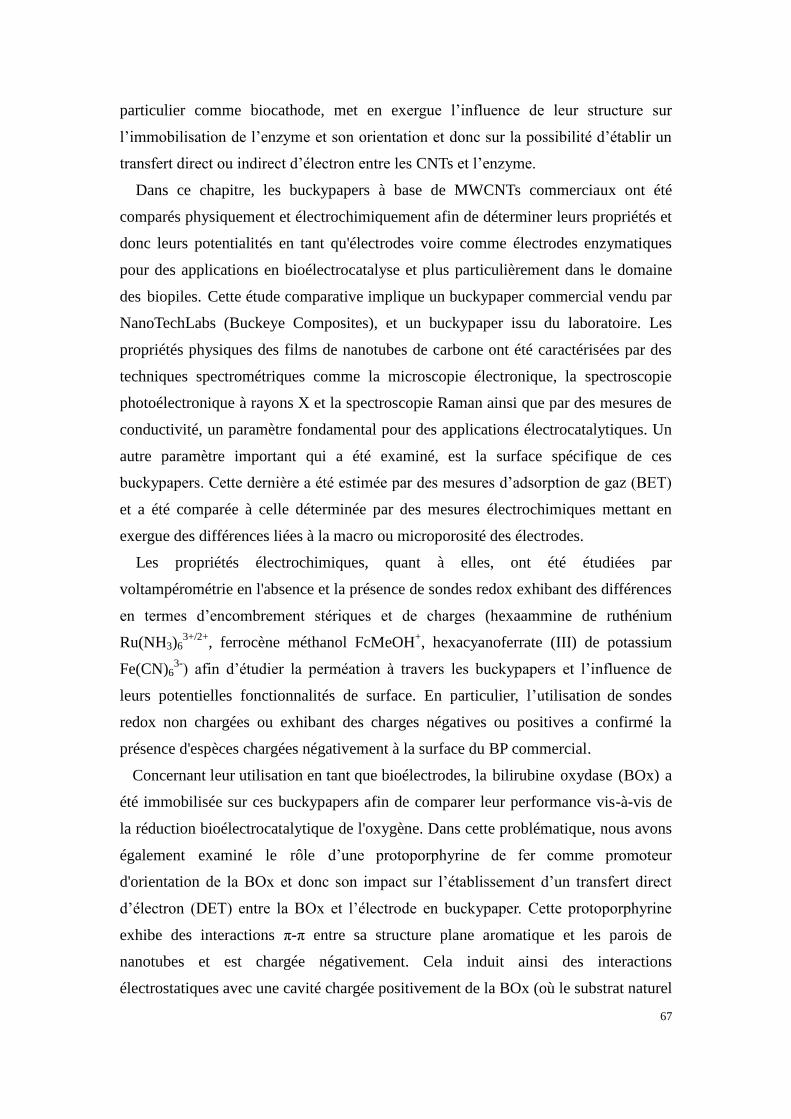
67
particulier comme biocathode, met en exergue l’influence de leur structure sur
l’immobilisation de l’enzyme et son orientation et donc sur la possibilité d’établir un
transfert direct ou indirect d’électron entre les CNTs et l’enzyme.
Dans ce chapitre, les buckypapers à base de MWCNTs commerciaux ont été
comparés physiquement et électrochimiquement afin de déterminer leurs propriétés et
donc leurs potentialités en tant qu'électrodes voire comme électrodes enzymatiques
pour des applications en bioélectrocatalyse et plus particulièrement dans le domaine
des biopiles. Cette étude comparative implique un buckypaper commercial vendu par
NanoTechLabs (Buckeye Composites), et un buckypaper issu du laboratoire. Les
propriétés physiques des films de nanotubes de carbone ont été caractérisées par des
techniques spectrométriques comme la microscopie électronique, la spectroscopie
photoélectronique à rayons X et la spectroscopie Raman ainsi que par des mesures de
conductivité, un paramètre fondamental pour des applications électrocatalytiques. Un
autre paramètre important qui a été examiné, est la surface spécifique de ces
buckypapers. Cette dernière a été estimée par des mesures d’adsorption de gaz (BET)
et a été comparée à celle déterminée par des mesures électrochimiques mettant en
exergue des différences liées à la macro ou microporosité des électrodes.
Les propriétés électrochimiques, quant à elles, ont été étudiées par
voltampérométrie en l'absence et la présence de sondes redox exhibant des différences
en termes d’encombrement stériques et de charges (hexaammine de ruthénium
Ru(NH3)63+/2+
, ferrocène méthanol FcMeOH+, hexacyanoferrate (III) de potassium
Fe(CN)63-
) afin d’étudier la perméation à travers les buckypapers et l’influence de
leurs potentielles fonctionnalités de surface. En particulier, l’utilisation de sondes
redox non chargées ou exhibant des charges négatives ou positives a confirmé la
présence d'espèces chargées négativement à la surface du BP commercial.
Concernant leur utilisation en tant que bioélectrodes, la bilirubine oxydase (BOx) a
été immobilisée sur ces buckypapers afin de comparer leur performance vis-à-vis de
la réduction bioélectrocatalytique de l'oxygène. Dans cette problématique, nous avons
également examiné le rôle d’une protoporphyrine de fer comme promoteur
d'orientation de la BOx et donc son impact sur l’établissement d’un transfert direct
d’électron (DET) entre la BOx et l’électrode en buckypaper. Cette protoporphyrine
exhibe des interactions π-π entre sa structure plane aromatique et les parois de
nanotubes et est chargée négativement. Cela induit ainsi des interactions
électrostatiques avec une cavité chargée positivement de la BOx (où le substrat naturel
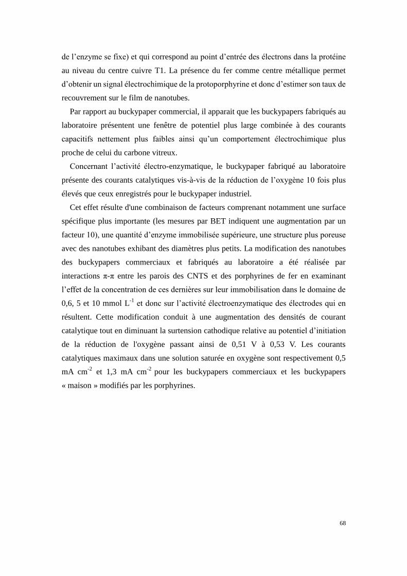
68
de l’enzyme se fixe) et qui correspond au point d’entrée des électrons dans la protéine
au niveau du centre cuivre T1. La présence du fer comme centre métallique permet
d’obtenir un signal électrochimique de la protoporphyrine et donc d’estimer son taux de
recouvrement sur le film de nanotubes.
Par rapport au buckypaper commercial, il apparait que les buckypapers fabriqués au
laboratoire présentent une fenêtre de potentiel plus large combinée à des courants
capacitifs nettement plus faibles ainsi qu’un comportement électrochimique plus
proche de celui du carbone vitreux.
Concernant l’activité électro-enzymatique, le buckypaper fabriqué au laboratoire
présente des courants catalytiques vis-à-vis de la réduction de l’oxygène 10 fois plus
élevés que ceux enregistrés pour le buckypaper industriel.
Cet effet résulte d'une combinaison de facteurs comprenant notamment une surface
spécifique plus importante (les mesures par BET indiquent une augmentation par un
facteur 10), une quantité d’enzyme immobilisée supérieure, une structure plus poreuse
avec des nanotubes exhibant des diamètres plus petits. La modification des nanotubes
des buckypapers commerciaux et fabriqués au laboratoire a été réalisée par
interactions π-π entre les parois des CNTS et des porphyrines de fer en examinant
l’effet de la concentration de ces dernières sur leur immobilisation dans le domaine de
0,6, 5 et 10 mmol L-1
et donc sur l’activité électroenzymatique des électrodes qui en
résultent. Cette modification conduit à une augmentation des densités de courant
catalytique tout en diminuant la surtension cathodique relative au potentiel d’initiation
de la réduction de l'oxygène passant ainsi de 0,51 V à 0,53 V. Les courants
catalytiques maximaux dans une solution saturée en oxygène sont respectivement 0,5
mA cm-2
et 1,3 mA cm-2
pour les buckypapers commerciaux et les buckypapers
« maison » modifiés par les porphyrines.

69
Chapter 2 Comparison of commercial and lab-made
MWCNT buckypaper: physicochemical properties and
bioelectrocatalytic O2 reduction
This chapter is based on the following manuscript-
Xiaohong Chen, Andrew J. Gross, Fabien Giroud, Michael Holzinger, Serge Cosnier
Electroanalysis. 2018, 30, 1511–1520
2.1 Abstract
The main goal of this thesis is to develop high-power enzymatic biofuel cells
(EFCs). Among various carbon nanostructured materials, buckypaper (BP) is one of
the most attractive materials to construct bioelectrodes due to its unique properties.
Therefore, it is necessary to examine different BPs to understand the bioelectrocatlytic
reaction on different electrode materials. In this chapter, a thorough comparison study
was conducted on commercial BP and lab-made BP. The former was obtained from
Buckeye Composite, while the latter was prepared in the lab using vacuum filtration
method. The two types of BPs were characterized using different techniques. The
behaviors of enzyme-modified bioelectrodes prepared from these two types of BPs
were examined by immobilizing bilirubin oxidase (BOx) for oxygen reduction.
2.2 Introduction
Nanostructured carbon materials such as carbon nanotubes (CNTs) and templated
mesoporous carbons have shown great promise as electrodes for enzymatic
bioelectrocatalysis for applications including biosensors and biofuel cells.1–5
CNT-based electrodes are attractive for bioelectrocatalysis owing to their properties
such as high conductivity, large specific surface area, exceptional mechanical strength,
and the ability to undergo efficient electron transfer with oxidoreductase enzymes.6,7
CNT electrodes also benefit from being readily modified with surface functionalities
via covalent and non-covalent methods, for example, to enhance the electrical “wiring”
and stabilization of enzymes for bioelectrocatalysis.8–10
Non-covalent surface
modification based on π-π stacking of pyrene derivatives and other polyaromatics on
nanotube sidewalls is a convenient strategy which retains the extended π-conjugation
of CNT networks and hence their electrical conductivity.10–14
Buckypaper is a very attractive type of CNT material which has emerged in recent
70
years for the construction of bioanodes and biocathodes for use in enzymatic biofuel
cells.13–19
Commercial BP has been used in actual implanted devices since 2012, most
notably, for in vivo biofuel cells and electronic device powering.16,18,20,21
BP is a
randomly ordered self-supporting film of CNTs which is typically formed by vacuum
filtration of aqueous and non-aqueous dispersions of CNTs.15,22,23
The films are
microscale-thin (ca. 5 to 300 μm) and held together by π-π stacking and interweaving
interactions.23,24
Unlike classical CNT electrodes, which are formed by depositing
CNT films on conductive glassy carbon and metal substrates, a BP film is the
electrode itself. BP electrodes are convenient to fabricate in the lab or can be obtained
from commercial sources.15,18
However, their electronic and physicochemical
properties are strongly dependent on factors such as the type of CNTs used (e.g.
length, diameter, quantity, defects and purity), dispersion homogeneity, the presence
of additives and the solvents used, which create challenges concerning reproducibility
and functionality.
For the construction of biocathodes, multi-copper oxidases (MCOs) such as
bilirubin oxidase and laccase are typically employed as the biocatalyst for the
four-electron reduction of O2 to H2O.25
These enzymes possess four Cu atoms with
the T1 Cu center, responsible for substrate oxidation and successive electron transfers,
located near the protein surface, and a tri-nuclear cluster of T2/T3 Cu centers which is
more deeply buried.26
Therefore, there is great interest in the development of
electrode-enzyme interfaces which permit the efficient orientation and electrical
connection of the T1 Cu center.
Hussein and coworkers developed the first buckypaper biocathodes (lab-made) by
adsorption of inks containing either BOx or laccase, ABTS
(2,2'-azino-bis(3-ethylbenzothiazoline-6-sulphonic acid)) mediator, and Nafion.23,27,30
In these series of work published in the same year, the best performing biocathode
achieved a maximum current density up to 0.7 mA cm-2
in oxygen-saturated buffer
via mediated electron transfer (MET) with BOx.27
Ciniciato et al. developed
air-breathing electrodes by fusing commercial BP with Toray paper and a carbon
black gas diffusion layer.28
This approach is attractive for enhancing the mass
transport of oxygen from air to the electrode surface, thus helping to address the
limited oxygen supply in quiescent aqueous solutions. The best performing
biocathode, based on direct electron transfer (DET) with BOx, delivered a current
output of ca. 0.7 mA cm-2
in buffer solution with capillary flow.28
Pankratov et al.

71
later reported the simple adsorption of BOx on different lab-made BP samples without
the use of Nafion as a binder.29
DET-type bioelectrocatalysis for oxygen reduction
was demonstrated but currents only up to 100 µA cm-2
were achieved, implying
limited catalytic activity of the nanotubes and a low enzyme loading.
Scherbahn et al. demonstrated that pyrroloquinoline quinone (PQQ) can be used as
an orientation promoter for DET with BOx on commercial buckypaper.14
PQQ was
effectively adsorbed on the electrode via π-π stacking interactions and gave a 5-fold
increase in catalytic currents up to 0.97 mA cm-2
in buffer solution compared to the
simple adsorption of BOx on unmodified electrodes. Minteer and coworkers
developed lab-made BPs modified with a pyrene-anthracene for oriented DET with
BOx.19
Although low catalytic currents of ca. 100 µA cm-2
were observed, this work
demonstrated that BP can be an excellent material for the construction of wearable
contact-lens bioelectrodes. Our group has also demonstrated the use of an orientation
promoter, protoporphyrin, to enhance DET with BOx on buckypaper.15
Well-defined
voltammetry and high limiting currents up to 1.33 mA cm-2
were observed in
oxygen-saturated buffer with purging, highlighting the promising electrochemical and
catalytic performance of these lab-made buckypapers.
Buckypaper is now an important electrode material for the development of
enzymatic biocathodes, yet little attention has been given to establishing their
electrochemical and physicochemical properties and how these properties influence
DET-type bioelectrocatalysis. The reported studies have until now focused on the
development of reliable fabrication methods and enzyme wiring strategies to improve
catalytic outputs in vivo and in vitro.
In this chapter, a comparative study was conducted which establishes a baseline
for the electrochemical properties of two prominent types of buckypapers: a
commercial buckypaper from an established source, NanoTechLabs Inc. (Buckeye
Composites), and a recently reported lab-made buckypaper with promising electrode
properties.15
In addition, this study compares the physicochemical properties and the
bioelectrocatalytic oxygen reduction activity of unmodified and iron-protoporphyrin
modified buckypapers with immobilized BOx.
2.3 Results and discussion
2.3.1 Physical properties of commercial and lab-made buckypaper

72
2.3.1.1 Scanning electron microscopy
Figure 2.1 shows top-down and cross-sectional scanning electron microscopy
(SEM) images of commercial BP and lab-made BP (defined as c-BP and l-BP in the
following context). The c-BP samples display a random, homogeneous and largely
macroporous structure (Figure 2.1A). The CNTs of the c-BP have large diameters of
75-200 nm. On the other hand, l-BP has a random but homogeneous mesoporous
structure of bundled CNTs (Figure 2.1B). The CNTs of l-BP have diameters of 10-20
nm. Cross-sectional images revealed that c-BP has a looser structure with wider
interlayer separations (Figure 2.1C). A denser and more compact structure is
observed for l-BP (Figure 2.1D).
Figure 2.1 SEM images showing (A, B) top-down and (C, D) cross-sectional views of (left) c-BP and
(right) l-BP
2.3.1.2 Film thickness, specific surface area and pore size
The average BP thicknesses were estimated to be 227 ± 14 µm (n = 3) and 269 ± 11
µm (n = 5) for the commercial and lab-made BPs, respectively, which is in the range
of other BPs obtained from vacuum filtration.13,15,23
The specific surface area and pore
size of the BPs were obtained from nitrogen sorption measurements (Figure 2.2),
which is a typical method for the characterization of microporous and mesoporous
solids.31
Brunauer-Emmett-Teller (BET) method is then applied to calculate the total
specific surface area. Barrett-Joyner-Halenda (BJH) analysis is subsequently

73
employed to evaluate pore size and volume from nitrogen desorption isotherms.
Figure 2.2 Nitrogen adsorption and desorption isotherms of (left) c-BP and (right) l-BP
The BET total specific surface area and BJH mesopore size of the BPs are
summarized in Table 2.1. The c-BP has a surface area of only 30.2 m2 g
-1. In contrast,
l-BP has an estimated surface area of 264 m2 g
-1, which is comparable to previously
reported values of 331 m2g
-1 and 180 m
2g
-1 for BP materials.
32,33 The l-BP has an
almost 9-fold larger surface area than c-BP. This is consistent with the l-BP having a
significantly more mesoporous structure, which is supported by the SEM imaging.
The average BJH pore diameter for both materials (noting that the analysis does not
account for macropores) was on the same order of magnitude for both BPs with
values of 17.0 nm and 14.6 nm for c-BP and l-BP, respectively. The total pore volume,
which also accounts for micropores (˂ 2 nm) and mesopores (2-50 nm), but not
macropores (˃ 50 nm), was negligible for c- BP but significant for l-BP, hence further
confirming that c-BPs have a more macroporous structure and that l-BPs are
significantly mesoporous.
Table 2.1 Surface area and pore size data from N2 sorption isotherms for commercial and lab-made BP
Sample
BET surface
area /m2 g
-1
BJH mesopores
Pore
diameter
/nm
Pore
volume /
cm3 g
-1
c-BP 30.2 17.0 4.3 × 10⁻⁴
l-BP 264 14.6 2.0
2.3.1.3 X-ray photoelectron spectroscopy, SEM-Energy dispersive x-ray spectroscopy
and Raman spectroscopy
The elemental composition, purity and extent of surface defects at the surface of the

74
BPs were characterized by XPS and Raman spectroscopy. XPS analysis revealed an
elemental composition of only carbon, nitrogen and oxygen at the BPs. The survey
spectra are shown in Figure 2.3. The quantitative analysis is summarized in Table 2.2.
The surface of c-BP contains mostly carbon (95.0%), considerable oxygen content
(4.4%) and some residual nitrogen (0.6%). The l-BP is also dominated by carbon
(98.8%) but possesses significantly less oxygen (1.2%) and no nitrogen. The survey
spectra (Figure 2.3) for both c-BP and l-BP are largely dominated by the C1s
envelope at 284.4 eV, which corresponds to the expected sp2 structure of the CNTs.
Other contributions at 285.3 eV and 289 eV account for hydroxyl and/or sp3
carbons,
and carboxylic acid groups, respectively. Unlike the l-BP spectrum, the c-BP spectrum
displays a clear contribution at 286.3 eV, representing surface carbonyl groups.
Figure 2.3 (Left) XPS survey spectra and (right) C1s high resolution spectra for (black) c-BP and (red)
l-BP substrates
Table 2.2 XPS elemental analysis for c-BP and l-BP surfaces
Sample Atomic %
C O N
c-BP 95.0 4.4 0.6
l-BP 98.8 1.2 /

75
Figure 2.4 SEM-EDS analysis: SEM images showing (A, B) secondary electron detector
(Everhart-Thornley; ETD) for topographic visualization and (C, D) backscattered electron detector
(BSD) for chemical contrast of the impurities distribution of (left) c-BP and (right) l-BP. Global EDS
spectra of the same area as above for (E) c-BP and (F) l-BP
XPS is a surface analysis technique, which normally probes a sampling depth of
around 10nm. Therefore, the obtained elemental analysis was limited to the exposed
surface of the BP layer to the XPS beam. Given the thick diameter of MWCNTs in
c-BP, SEM-energy dispersive x-ray spectroscopy (SEM-EDS) was performed to probe
the deeper layer below the surface (Figure 2.4). These analyses suggest that CNTs
used in the formation of the c-BPs do possess some Fe content (residual catalyst),
which are typical impurities of CNTs.34
In contrast, CNTs used for making l-BPs
contains either no Fe content or only trace levels.

76
Raman spectroscopy was also performed to characterize the surface structure, and
in particular, the extent of defect sites in the buckypapers (Figure 2.5). Two major
bands at approximately 1350 cm-1
and 1580 cm-1
are present in the Raman spectra,
corresponding to the D-band (disordered sp2 carbon) and G-band (crystalline sp
2
carbon), respectively. The ratio of the D and G band intensities was used to provide a
relative but not quantitative comparison of the two BP samples. The c-BP has a
comparably more ordered and higher structural purity/crystallinity structure (ID/IG =
0.52) while l-BP has a more apparent defective surface (ID/IG = 1.74).
Figure 2.5 Raman spectrums of (black) c-BP and (red) l-BP of the region between 1000 and 2000 cm-1
2.3.1.4. Contact angle, surface profilometry and electrical conductivity
Water contact angle (CA) measurements were performed on c-BP and l-BP. Similar
values of 134 ± 8° and 127 ± 18° were obtained for c-BP and l-BP, respectively,
which is consistent with both surfaces being hydrophobic (˃90°). It was considered
that the c-BP, with its high surface oxygen content, might be more hydrophilic than
l-BP, but this was not the case. The surface roughness and heterogeneity, rather than
the chemical modification, therefore appears to have a more influential effect on the
wetting behavior of BP.
Surface profilometry imaging using 3D optical microscopy over large areas of ca.
100 µm2 revealed further insight into the surface structure of the BPs. A larger
average roughness value of 4.8 µm root mean square roughness (rms) was estimated
for c-BP compared to a value of 1.9 µm rms for l-BP. The profilometry clearly shows
that the c-BP has greater surface roughness, which helps to explain its hydrophobicity
despite the higher surface oxygen content.35
The electrical conductivity of c-BP and l-BP was measured with a four-point probe
and revealed average values of 22 ± 3 S cm-1
and 13 ± 1 S cm-1
, respectively. These

77
results are similar to conductivity values of around 20-30 S cm-1
reported for
randomly ordered BP.23,30,36
The lower electrical conductivity for l-BP, despite the
more compact and interconnected structure, can be attributed to the increase of
sp3-type carbon (e.g. higher defect) carbon structure inferred from the Raman spectra.
2.3.2 Electrochemical characterization of commercial and lab-made BPs
Figure 2.6 shows the background voltammetric response recorded at the two BP
electrodes in 0.1 mol L-1
phosphate buffer (PB) at a scan rate of 20 mV s-1
. The two
electrodes were scanned between -0.9 V and 1.0 V vs. SCE, which is a relevant
potential window to observe the electrochemical stability of carbon electrodes in
aqueous solution.37
The c-BP electrode unexpectedly exhibits a pair of redox peaks at
Epc = -0.2 V and Epa = 0.5 V. In contrast, the l-BP electrodes exhibited a steady
capacitive current response over the same potential range. The redox peaks at c-BP
are attributed to electroactive surface-bound oxygen functionalities such as
polyaromatic carbonyl, nitroso and phenol groups. The possibility that the redox
peaks are due to metal oxides is not entirely ruled out on the basis that Fe impurities
were observed by SEM-EDS (Figure 2.4). The c-BP electrode showed a 10-fold
larger background capacitive current. The larger capacitance observed at c-BP is
attributed to the looser packing density of CNT bundles (Figure 2.1C), increased
surface roughness and the higher concentration of oxygen functionalities.
Figure 2.6 Representative cyclic voltammograms recorded at (black) c-BP and (red) l-BP electrodes in
0.1 mol L-1
PB (pH 7.0) solution at 20 mV s-1
Next the electron transfer reactivity of c-BP and l-BP electrodes with four different
redox probes was evaluated by cyclic voltammetry experiments. The midpoint
potential (Em), peak-to-peak potential separation (ΔEP), electroactive surface area
(ECSA) and heterogeneous rate constant (k°) of the BP electrodes are summarized in
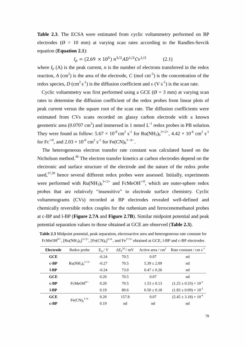
78
Table 2.3. The ECSA were estimated from cyclic voltammetry performed on BP
electrodes (Ø = 10 mm) at varying scan rates according to the Randles-Sevcik
equation (Equation 2.1):
𝐼𝑝 = (2.69 × 10⁵) 𝑛3/2𝐴𝐷1/2𝐶𝜈1/2 (2.1)
where Ip (A) is the peak current, n is the number of electrons transferred in the redox
reaction, A (cm2) is the area of the electrode, C (mol cm
-3) is the concentration of the
redox species, D (cm2
s-1
) is the diffusion coefficient and υ (V s-1
) is the scan rate.
Cyclic voltammetry was first performed using a GCE (Ø = 3 mm) at varying scan
rates to determine the diffusion coefficient of the redox probes from linear plots of
peak current versus the square root of the scan rate. The diffusion coefficients were
estimated from CVs scans recorded on glassy carbon electrode with a known
geometric area (0.0707 cm2) and immersed in 1 mmol L
-1 redox probes in PB solution.
They were found as follow: 5.67 × 10⁻⁸
cm2 s
-1 for Ru(NH3)6
3+/2+, 4.42 × 10
-6 cm
2 s
-1
for Fc+/0
, and 2.03 × 10⁻⁶
cm2 s
-1 for Fe(CN)6
3−/4−.
The heterogeneous electron transfer rate constant was calculated based on the
Nicholson method.38
The electron transfer kinetics at carbon electrodes depend on the
electronic and surface structure of the electrode and the nature of the redox probe
used,37,39
hence several different redox probes were assessed. Initially, experiments
were performed with Ru(NH3)63+/2+
and FcMeOH+/0
, which are outer-sphere redox
probes that are relatively “insensitive” to electrode surface chemistry. Cyclic
voltammograms (CVs) recorded at BP electrodes revealed well-defined and
chemically reversible redox couples for the ruthenium and ferrocenemethanol probes
at c-BP and l-BP (Figure 2.7A and Figure 2.7B). Similar midpoint potential and peak
potential separation values to those obtained at GCE are observed (Table 2.3).
Table 2.3 Midpoint potential, peak separation, electroactive area and heterogeneous rate constant for
FcMeOH0/+
, [Ru(NH3)6]3+/2+
, [Fe(CN)6]3-/4-
, and Fe2+/3+
obtained at GCE, l-BP and c-BP electrodes
Electrode Redox probe Em / V ΔEP[a]
/ mV Active area / cm2 Rate constant / cm s
-1
GCE
Ru(NH3)63+/2+
-0.24 70.5 0.07 nd
c-BP -0.27 70.5 5.39 ± 2.09 nd
l-BP -0.24 73.0 0.47 ± 0.26 nd
GCE
FcMeOH0/+
0.20 70.5 0.07 nd
c-BP 0.20 70.5 1.53 ± 0.13 (1.25 ± 0.33) × 10-2
l-BP 0.19 80.6 0.50 ± 0.18 (1.83 ± 0.09) × 10-2
GCE Fe(CN)6
3-/4-
0.20 157.8 0.07 (5.45 ± 3.18) × 10-4
c-BP 0.19 nd nd nd
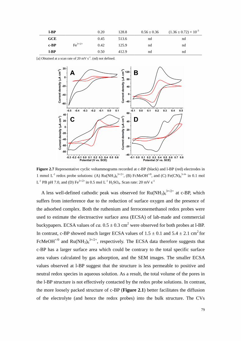
79
l-BP 0.20 128.8 0.56 ± 0.36 (1.36 ± 0.72) × 10-3
GCE
Fe3+/2+
0.45 513.6 nd nd
c-BP 0.42 125.9 nd nd
l-BP 0.50 412.9 nd nd
[a] Obtained at a scan rate of 20 mV s-1
. (nd) not defined.
Figure 2.7 Representative cyclic voltammograms recorded at c-BP (black) and l-BP (red) electrodes in
1 mmol L-1
redox probe solutions: (A) Ru(NH3)63+/2+
, (B) FcMeOH+/0
, and (C) Fe(CN)63-/4-
in 0.1 mol
L-1
PB pH 7.0, and (D) Fe3+/2+
in 0.5 mol L-1
H2SO4. Scan rate: 20 mV s-1
A less well-defined cathodic peak was observed for Ru(NH3)63+/2+
at c-BP, which
suffers from interference due to the reduction of surface oxygen and the presence of
the adsorbed complex. Both the ruthenium and ferrocenemethanol redox probes were
used to estimate the electroactive surface area (ECSA) of lab-made and commercial
buckypapers. ECSA values of ca. 0.5 ± 0.3 cm2 were observed for both probes at l-BP.
In contrast, c-BP showed much larger ECSA values of 1.5 ± 0.1 and 5.4 ± 2.1 cm2 for
FcMeOH+/0
and Ru(NH3)63+/2+
, respectively. The ECSA data therefore suggests that
c-BP has a larger surface area which could be contrary to the total specific surface
area values calculated by gas adsorption, and the SEM images. The smaller ECSA
values observed at l-BP suggest that the structure is less permeable to positive and
neutral redox species in aqueous solution. As a result, the total volume of the pores in
the l-BP structure is not effectively contacted by the redox probe solutions. In contrast,
the more loosely packed structure of c-BP (Figure 2.1) better facilitates the diffusion
of the electrolyte (and hence the redox probes) into the bulk structure. The CVs

80
obtained at c-BP, but not l-BP, also show evidence for the weak adsorption of both the
ferrocene and ruthenium species as larger oxidative peaks than reduction peaks were
observed. The adsorbed electroactive species contribute to the peak current and
therefore, to some extent, result in an overestimation of the ECSA values at c-BP. The
ECSA value at c-BP was 3.5-fold larger using the larger Ru(NH3)63+/2+
probe which
reflects that this complex adsorbs to a greater extent at c-BP compared to FcMeOH.
The adsorption of positively charged Ru(NH3)63+/2+
and FcMeOH+ at c-BP can occur
via electrostatic interactions between surface bound oxygen residues, which would be
negatively charged at neutral pH, and the positively charged oxidized species. The
possibility that the reduced neutral form of FcMeOH adsorbs at the oxidized graphitic
surface is not ruled out.40
Electron transfer rates at the buckypapers were estimated based on the FcMeOH+/0
probe and revealed slower heterogeneous electron transfer at c-BP compared to l-BP,
which is attributed to differences in the physical and electronic structure of the CNTs.
For example, Banks et al. have shown that catalytic electron transfer on CNTs relies
on edge-plane sites and tube ends.41
It is possible that l-BP, which has shorter and
smaller diameter CNT bundles with a more defective structure, benefit from having
more exposed edge-plane like sites.
Fe(CN)63-/4-
is a well-known surface-sensitive redox probe. At c-BP, the redox
peaks for this probe are poorly defined. In addition to the weak signal, we observe the
redox activity of the oxide groups at -0.2 V and 0.5 V. The ferricyanide redox couple
was unfortunately not sufficiently resolved at c-BP to obtain kinetic or surface area
data. A well-defined electrochemical response, similar to that observed at GCE, was
observed at l-BP. Faster electron transfer by more than 2-fold was observed at l-BP
compared to glass carbon electrode (GCE), highlighting the benefits of l-BP as an
advanced type of carbon electrode. Both GCE and l-BP exhibited slower electron
transfer kinetics towards Fe(CN)63-/4-
compared to Ru(NH3)63+/2+
, which is typical for
carbon electrodes.37
The estimated ECSA value for l-BP of 0.56 cm2 using
Fe(CN)63-/4-
is very similar to the ca. 0.5 cm2 areas estimated using the ferrocene and
ruthenium probes at l-BP. The similar ECSA values for all three probes suggests that
l-BP is less sensitive to charged species and adsorption effects compared to c-BP.
To further assess the presence and activity of oxygen species on the CNT surface of
c-BP, a more specific surface-sensitive redox probe was also investigated. The Fe3+/2+
redox probe was chosen as it is known to be highly sensitive to surface oxide.30
CVs

81
recorded at the oxygen-rich c-BP showed a reversible couple of the probe with a small
peak separation of 126 mV, consistent with “fast” apparent electron transfer kinetics.
Additional redox peaks were also present, which appear to be due to the presence of
the surface oxide groups which promote a positive shift in potential. In contrast, a
much larger peak separation of 413 mV was observed at l-BP, highlighting slower
electron transfer behavior at l-BP compared to c-BP. The exact nature of the complex
redox behavior is not clear. Nevertheless, the data obtained using the Fe3+/2+
probe,
which reveals a strong interaction of the iron complex with c-BP but not l-BP,
provides supporting evidence for the presence of surface oxygen groups.
2.3.3 Bioelectrocatalytic activity of BOx-modified commercial and
lab-made BPs
The buckypapers were investigated for the construction of enzymatic bioelectrodes
for bioelectrocatalysis. In this study, the bioelectrocatalytic reduction of O2 to water
was explored. Oxygen reduction reaction (ORR) is currently the most studied reaction
for cathodes in enzymatic biofuel cell research. ORR is investigated here, using
adsorbed BOx as the biocatalyst, and relies on direct electron transfer between the
electrode and the tri-nuclear Cu centre of the immobilized enzymes.
Figure 2.8A shows CVs recorded for bioelectrocatalytic O2 reduction at BOx
modified l-BP and c-BP electrodes. Under O2-saturated conditions, both BPs
displayed onset potentials of 0.51 ± 0.01 V, which is in good agreement with DET
mechanism through the T1 Cu center (the theoretical value of the ET1, Cu = 0.43 V vs.
SCE).42
For c-BP, the catalytic current density (Jcat) is negligible (-23 ± 15 µA cm-2
).
For l-BP, the catalytic current density was 9-fold larger and reached -214 ± 74 µA
cm-2
at 0.3 V. This current density is similar to our previous results obtained at
unmodified BP with adsorbed BOx (-225 ± 91 µA cm-2
) under equivalent
conditions.15
The improvement in DET–type bioelectrocatalysis for unmodified l-BP
compared to unmodified c-BP was expected as l-BP has a significantly higher total
specific BET surface area and a more defective CNT structure (e.g. more reactive
vacancies). Although c-BP electrodes show larger electroactive surface area, the
experiments for determination of the ECSA values with different redox probes were
performed at a time scale of several minutes. For bioelectrocatalytic studies, enzymes
were left to adsorb overnight on the surface, allowing enzymes to diffuse into the BP

82
matrix.
Enhancements in DET at BOx modified CNT electrodes are also strongly related to
the presence of negatively-charged surface groups which orientate the enzyme via
arginine residues near the T1 Cu center.43–45
It was therefore postulated that the
oxygen-rich c-BP, with negatively-charged surface groups at pH 7.0, would promote a
stronger DET response compared to l-BP. This is however not the case. The surface
charge and the presence of oxygen groups are therefore relatively insignificant factors
for DET bioelectrocatalysis at buckypaper. Hence, the overall charge of the BOx at
pH 7.0 (pI = 4.1) is apparently not a crucial factor for its orientation. On the contrary,
a large specific surface area and the type and structure of CNTs in the buckypaper (e.g.
the π-π network and CNT dimensions5,43,46,47
) are expected to play a greater role in
favoring BOx immobilization. For example, concerning the type of CNTs used,
Mugurama et al. elegantly reported the importance of the size of CNTs for achieving
DET-type bioelectrocatalysis.46
Figure 2.8 Representative cyclic voltammograms for (A) unmodified, (B) H0.6 and (C) H5 modified
c-BPs (black) and l-BPs (red) with adsorbed BOx at the electrode surfaces in quiescent (dashes)
Ar-saturated or (lines) O2-saturated in pH 7.0 PB solution (1 mV s-1
, 1st scan displayed)
Next, the role of CNT size on the DET bioelectrocatalysis with immobilized BOx
was considered. Based on the average outer diameter of the CNTs of c-BP, estimated

83
from SEM images, the nanotubes of c-BP were postulated to represent a flatter
surface upon interaction with the enzyme (assuming the tube as a disk near the
pocket). Figure 2.9 shows a 3D structural view of the enzyme and highlights the
hydrophilic substrate pocket, where the active site is located. Based on the distances
between each arginine residue, the pocket is estimated to be 1.5 nm in width. To
estimate the relative area of an individual tube (represented as a disk) which enters the
substrate pocket, the angle describing the arc length of the substrate pocket for the
tube was calculated. The larger the angle, the more the individual tube can penetrate
inside the pocket. As an example, a hypothetical 1.5 nm diameter tube, which would
perfectly fill the entrance of the substrate pocket, would have a 180° arc angle and
would represent 50% of the total area of the disk described. On this basis, the arc
angle for an average CNT tube of c-BP (ca. 137 nm diameter based on SEM imaging)
is only 1.3°. Consequently, the arc segment area of an average CNT in c-BP that could
penetrate the pocket would represent only 0.00003% of its total projected disk area. In
contrast, the average CNT of l-BP (ca. 15 nm diameter based on SEM imaging) can
better penetrate the substrate pocket with an arc angle of 11.5° representing 0.02% of
the total projected disk area of the CNT entering the substrate pocket.
Figure 2.9 Resolved bilirubin oxidase protein structure from Myrothecium verrucaria highlighting four
arginine residues located near the T1 copper centre of the enzyme. (PDB code: 2XLL)
With the aim to increase the favorable adsorption and orientation of BOx on the
electrode, the two different buckypapers were modified with hemin, an
iron-protoporphyrin with a substrate-like structure, via π-π stacking interactions.15,44
Hemin-modified BP electrodes (c-BP-H and l-BP-H) were prepared by drop-casting
T1 copper
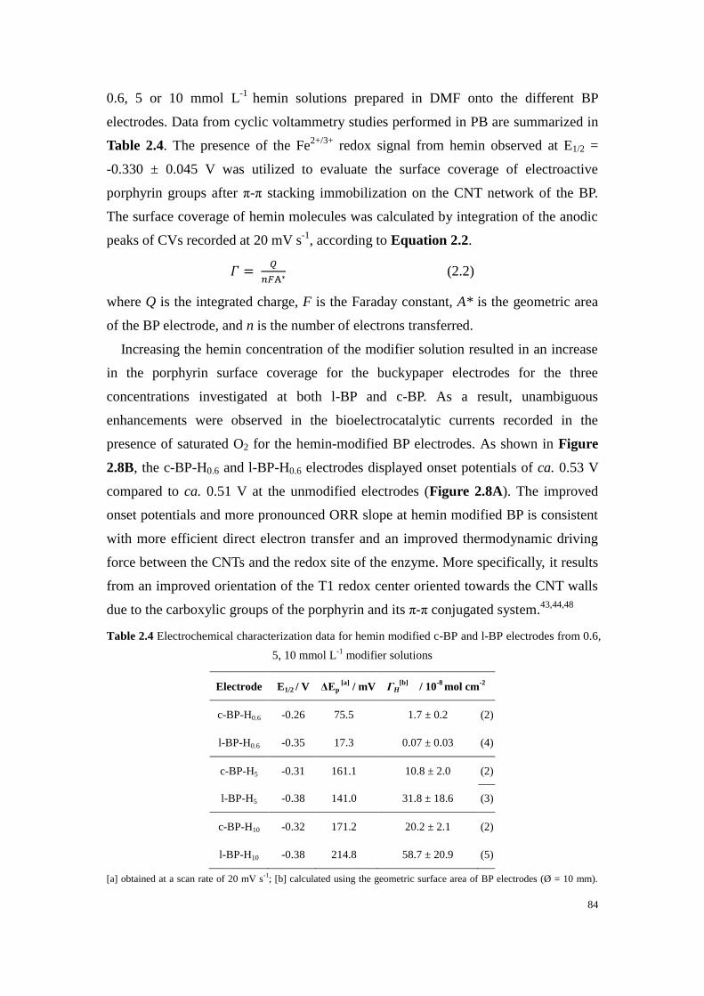
84
0.6, 5 or 10 mmol L-1
hemin solutions prepared in DMF onto the different BP
electrodes. Data from cyclic voltammetry studies performed in PB are summarized in
Table 2.4. The presence of the Fe2+/3+
redox signal from hemin observed at E1/2 =
-0.330 ± 0.045 V was utilized to evaluate the surface coverage of electroactive
porphyrin groups after π-π stacking immobilization on the CNT network of the BP.
The surface coverage of hemin molecules was calculated by integration of the anodic
peaks of CVs recorded at 20 mV s-1
, according to Equation 2.2.
𝛤 = 𝑄
𝑛𝐹A∗ (2.2)
where Q is the integrated charge, F is the Faraday constant, A* is the geometric area
of the BP electrode, and n is the number of electrons transferred.
Increasing the hemin concentration of the modifier solution resulted in an increase
in the porphyrin surface coverage for the buckypaper electrodes for the three
concentrations investigated at both l-BP and c-BP. As a result, unambiguous
enhancements were observed in the bioelectrocatalytic currents recorded in the
presence of saturated O2 for the hemin-modified BP electrodes. As shown in Figure
2.8B, the c-BP-H0.6 and l-BP-H0.6 electrodes displayed onset potentials of ca. 0.53 V
compared to ca. 0.51 V at the unmodified electrodes (Figure 2.8A). The improved
onset potentials and more pronounced ORR slope at hemin modified BP is consistent
with more efficient direct electron transfer and an improved thermodynamic driving
force between the CNTs and the redox site of the enzyme. More specifically, it results
from an improved orientation of the T1 redox center oriented towards the CNT walls
due to the carboxylic groups of the porphyrin and its π-π conjugated system.43,44,48
Table 2.4 Electrochemical characterization data for hemin modified c-BP and l-BP electrodes from 0.6,
5, 10 mmol L-1
modifier solutions
Electrode E1/2 / V ΔEp [a]
/ mV ΓH[b]
/ 10-8
mol cm-2
c-BP-H0.6 -0.26 75.5 1.7 ± 0.2 (2)
l-BP-H0.6 -0.35 17.3 0.07 ± 0.03 (4)
c-BP-H5 -0.31 161.1 10.8 ± 2.0 (2)
l-BP-H5 -0.38 141.0 31.8 ± 18.6 (3)
c-BP-H10 -0.32 171.2 20.2 ± 2.1 (2)
l-BP-H10 -0.38 214.8 58.7 ± 20.9 (5)
[a] obtained at a scan rate of 20 mV s-1
; [b] calculated using the geometric surface area of BP electrodes (Ø = 10 mm).
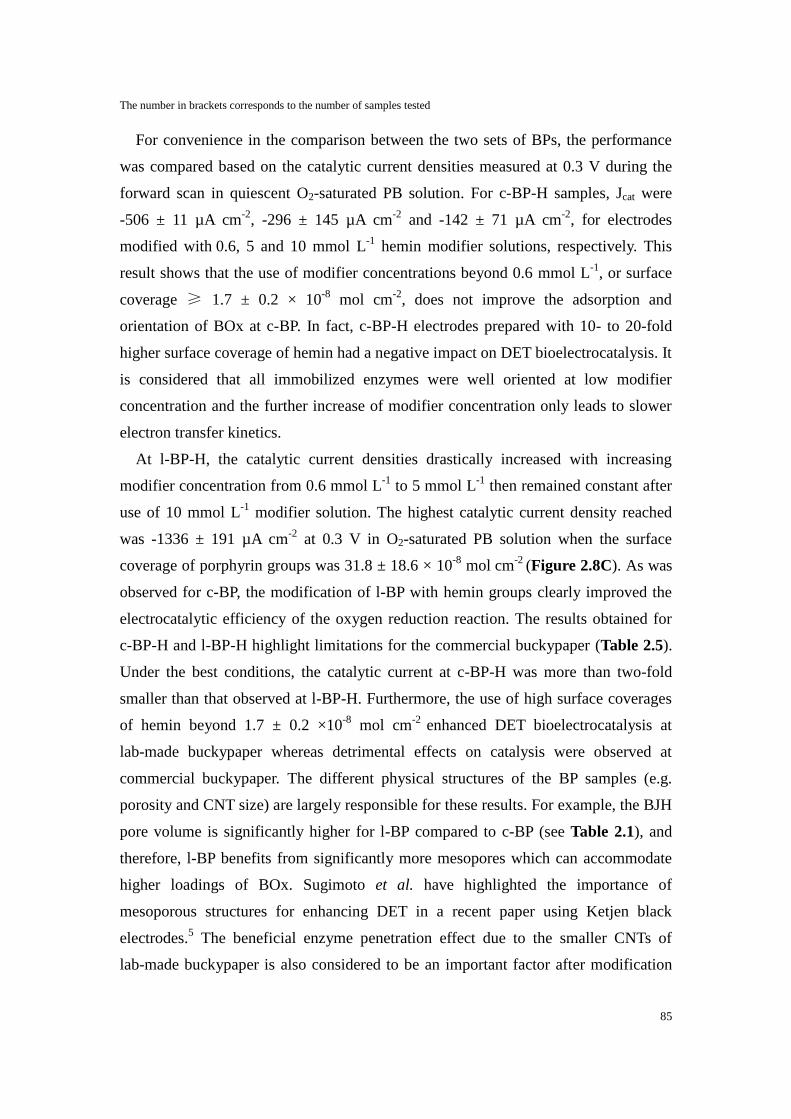
85
The number in brackets corresponds to the number of samples tested
For convenience in the comparison between the two sets of BPs, the performance
was compared based on the catalytic current densities measured at 0.3 V during the
forward scan in quiescent O2-saturated PB solution. For c-BP-H samples, Jcat were
-506 ± 11 µA cm-2
, -296 ± 145 µA cm-2
and -142 ± 71 µA cm-2
, for electrodes
modified with 0.6, 5 and 10 mmol L
-1 hemin modifier solutions, respectively. This
result shows that the use of modifier concentrations beyond 0.6 mmol L-1
, or surface
coverage ≥ 1.7 ± 0.2 × 10⁻⁸
mol cm-2
, does not improve the adsorption and
orientation of BOx at c-BP. In fact, c-BP-H electrodes prepared with 10- to 20-fold
higher surface coverage of hemin had a negative impact on DET bioelectrocatalysis. It
is considered that all immobilized enzymes were well oriented at low modifier
concentration and the further increase of modifier concentration only leads to slower
electron transfer kinetics.
At l-BP-H, the catalytic current densities drastically increased with increasing
modifier concentration from 0.6 mmol L-1
to 5 mmol L-1
then remained constant after
use of 10 mmol L-1
modifier solution. The highest catalytic current density reached
was -1336 ± 191 µA cm-2
at 0.3 V in O2-saturated PB solution when the surface
coverage of porphyrin groups was 31.8 ± 18.6 × 10⁻⁸
mol cm-2
(Figure 2.8C). As was
observed for c-BP, the modification of l-BP with hemin groups clearly improved the
electrocatalytic efficiency of the oxygen reduction reaction. The results obtained for
c-BP-H and l-BP-H highlight limitations for the commercial buckypaper (Table 2.5).
Under the best conditions, the catalytic current at c-BP-H was more than two-fold
smaller than that observed at l-BP-H. Furthermore, the use of high surface coverages
of hemin beyond 1.7 ± 0.2 ×10⁻⁸
mol cm-2
enhanced DET bioelectrocatalysis at
lab-made buckypaper whereas detrimental effects on catalysis were observed at
commercial buckypaper. The different physical structures of the BP samples (e.g.
porosity and CNT size) are largely responsible for these results. For example, the BJH
pore volume is significantly higher for l-BP compared to c-BP (see Table 2.1), and
therefore, l-BP benefits from significantly more mesopores which can accommodate
higher loadings of BOx. Sugimoto et al. have highlighted the importance of
mesoporous structures for enhancing DET in a recent paper using Ketjen black
electrodes.5 The beneficial enzyme penetration effect due to the smaller CNTs of
lab-made buckypaper is also considered to be an important factor after modification

86
of the surface with porphyrin molecules.
Table 2.5 Catalytic performance data for unmodified and hemin modified c-BP and l-BP electrodes
Electrode Eonset[a]
/ mV Jcat[b]
/ µA cm-2
c-BP 506 ± 10 -23 ± 15 (3)
l-BP 510 ± 10 -214 ± 74 (3)
c-BP-H0.6 526 ± 2 -506 ± 11 (2)
l-BP-H0.6 528 ± 6 -330 ± 88 (4)
c-BP-H5 505 ± 7 -296 ± 145 (2)
l-BP-H5 542 ± 8 -1336 ± 191 (3)
c-BP-H10 480 ± 4 -142 ± 71 (2)
l-BP-H10 539 ± 6 -1313 ± 61 (5)
[a] for oxygen reduction reaction under oxygen-saturated conditions with no purging or convection; [b] obtained at 0.3 V
during the forward scan at 1 mV s-1
. Number in brackets represents the number of samples for each configuration.
Another key difference in the electrocatalytic behavior between the lab-made and
commercial buckypaper electrodes is that, at the best performing l-BP-H5 electrode, a
large catalytic reduction peak was observed at 0.3 V which reached a pseudo
“steady-state” at 0.1 V (Jcat = -0.420 mA cm-2
) (Figure 2.8). It is noted that similar
behavior was also observed at l-BP-H10 electrode (Figure 2.10). This is in sharp
contrast to the “resistive slope” observed at unmodified BP (reflecting random
enzyme orientation, Figure 2.8A) and the well-defined steady state-type
voltammograms observed at c-BP-H electrodes. The catalytic peak behavior was only
observed during the forward scan and is attributed to a mass transport limitation of
dissolved O2 through the compact 3D mesoporous architecture of the electrode. On
the reverse scan, no peak is observed as less oxygen is available in the bulk structure.
It is also evident that the slope of the catalytic reduction wave at l-BP-H5 (Figure
2.8C) and l-BP-H10 (Figure 2.10) is significantly steeper compared to the responses
observed at the hemin-modified c-BP electrodes, consistent with a faster rate of
oxygen reduction owing not only to the presence of high coverage of hemin but also
higher loadings of oriented BOx.
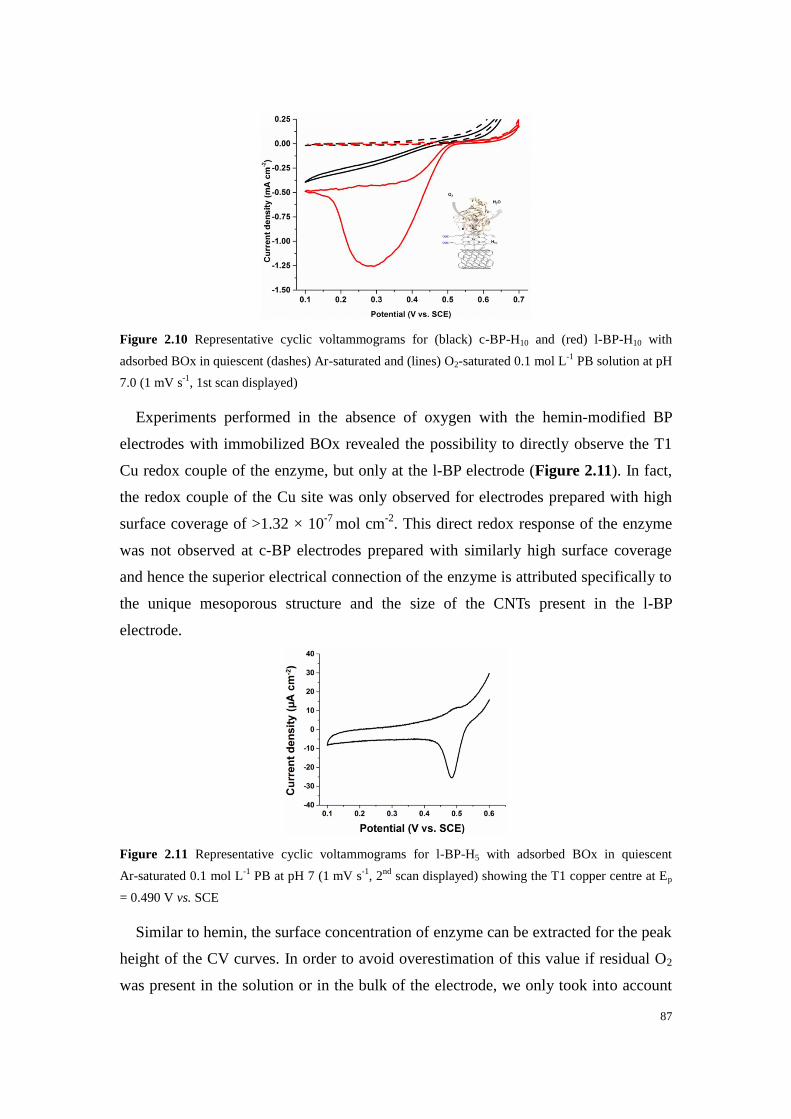
87
Figure 2.10 Representative cyclic voltammograms for (black) c-BP-H10 and (red) l-BP-H10 with
adsorbed BOx in quiescent (dashes) Ar-saturated and (lines) O2-saturated 0.1 mol L-1
PB solution at pH
7.0 (1 mV s-1
, 1st scan displayed)
Experiments performed in the absence of oxygen with the hemin-modified BP
electrodes with immobilized BOx revealed the possibility to directly observe the T1
Cu redox couple of the enzyme, but only at the l-BP electrode (Figure 2.11). In fact,
the redox couple of the Cu site was only observed for electrodes prepared with high
surface coverage of >1.32 × 10⁻⁷
mol cm-2
. This direct redox response of the enzyme
was not observed at c-BP electrodes prepared with similarly high surface coverage
and hence the superior electrical connection of the enzyme is attributed specifically to
the unique mesoporous structure and the size of the CNTs present in the l-BP
electrode.
Figure 2.11 Representative cyclic voltammograms for l-BP-H5 with adsorbed BOx in quiescent
Ar-saturated 0.1 mol L-1
PB at pH 7 (1 mV s-1
, 2nd
scan displayed) showing the T1 copper centre at Ep
= 0.490 V vs. SCE
Similar to hemin, the surface concentration of enzyme can be extracted for the peak
height of the CV curves. In order to avoid overestimation of this value if residual O2
was present in the solution or in the bulk of the electrode, we only took into account

88
the oxidation peak (non-catalytic) of the T1 Cu center. From this peak of the T1 site
(see Figure 2.11), the average surface coverage of enzyme on l-BP-H5 and l-BP-H10
was estimated to be 2.73 × 10⁻¹⁰
mol cm-2
, which is a significantly higher enzyme
loading compared to that previously reported at CNT modified GC electrodes with
immobilized BOx (5.0 × 10⁻¹²
mol cm-2
).44
2.4 Conclusion
In this study, the comparison of different grades of buckypaper (commercial and
lab-made) was performed in order to assess their physicochemical and catalytic
behavior. Very different physicochemical properties were reported, and these were
found to greatly influence the bioelectrocatalytic performance. Commercial BP
possesses a higher oxygen content but more ordered and looser structure with
significantly wider diameter nanotubes compared to our lab-made BP.
Electrochemical characterisation experiments revealed complexity for the commercial
BP owing to the presence of electroactive oxygen groups which also promoted
adsorption of positively-charged redox species and suffered from a short potential
window for a carbon electrode. The electrochemical potential window for l-BP was
1.6 V and the redox probe behavior was very classical to quasi-reversible systems
compared to other carbon electrodes. The electroactive surface area data contradicted
the BET surface area measurements. The lower than expected electroactive surface
area at l-BP suggests that the charged redox species did not effectively diffuse into the
denser mesoporous structure of l-BP during the time scale of the experiment.
Additionally, the electroactive surface area of c-BP is likely overestimated due to
adsorption effects via the negatively-charged surface oxygen at pH 7.0.
BP electrodes modified with BOx were studied and the best catalytic performance
at unmodified and hemin-modified electrodes was obtained at l-BP. At unmodified BP,
negligible DET was observed at commercial BP compared to the lab-made
counterpart. This suggests that the negatively charged oxygen groups did not promote
DET catalysis and that the structure of c-BP was less well suited to effective enzyme
adsorption and orientation. At hemin-modified CNT electrodes functionalized with
DET promoting porphyrin groups, enhanced currents were observed. The DET
enhancement at l-BP was superior and gave a current density of -1.32 mA cm-2
and a
very pronounced slope for the bioelectrocatalytic wave. Furthermore, the T1 Cu
centre was only observed using the l-BP, and only for high surface loadings of

89
porphyrin. The data points that highly mesoporous surface but also a high coverage of
hemin are required for effective DET-type bioelectrocatalysis with BOx at l-BP. This
is in contrast to c-BP which requires comparatively lower hemin coverage to obtain
optimal catalytic current outputs. This appears to be related to the 9-times smaller
BET surface area and likely similar reduction in the enzyme loading. All in all, this
report gives the baseline for electrochemical properties of two prominent types of BP
and demonstrates that several interdependent physico-chemical “features” play a large
role in the efficiency and complexity of bioelectrocatalytic systems.
2.5 Experimental section
2.5.1 Materials and reagents
Potassium phosphate dibasic, potassium phosphate monobasic,
N,N-dimethylformamide (DMF, 99.9%), hexaammineruthenium (III) chloride
(Ru(NH3)6, 98%), hemin (iron-protoporphyrin, ≥97%), potassium
hexacyanoferrate(III) (Fe(CN)6, ≥99.0%), sulfuric acid (95-97%) were purchased
from Sigma-Aldrich. Ferrocenemethanol (FcMeOH, 97%) was purchased from Acros
Organics. Iron (II) sulfate heptahydrate (≥99.0%) was purchased from Prolabo.
Bilirubin oxidase (BOx) from Myrothecium verrucaria (E.C. 1.3.3.5, estimated
activity: 8.36 U mg-1
)49
was purchased from Amano Enzyme. Commercial MWCNT
proprietary blend buckypaper (c-BP) with reference number NTL-12218 was obtained
from NanoTechLabs, Inc. Multi-walled carbon nanotubes (MWCNTs) (Ø = 9.5 nm,
purity >95%, 1.5 μm length) were obtained from Nanocyl and used for lab-made
buckypaper (l-BP) fabrication. Distilled deionized water (15 MΩ) was obtained from
an ELGA PURELAB purification system. Oxygen and argon were purchased from
Air Liquide (France). Potassium phosphate buffer (PB) was prepared from potassium
phosphate dibasic and potassium phosphate monobasic solutions and adjusted to pH
7.0.
2.5.2 Characterization methods
2.5.2.1 Morphology
High resolution images of BP morphology were obtained using a FEI/Quanta FEG
250 scanning electron microscope (SEM, Hillsboro, OR, USA) with an accelerating
voltage of 5 kV. Cross-sectional images of the interlayer structures were snapped after

90
gently breaking the BP samples.
2.5.2.2 Physical
BP thicknesses were measured using vernier calipers. BP electrical conductivity
was measured using a Keithley 2450 SourceMeter with an S-302-4 mounting stand
and SP4 four-point probe head. Average values were obtained from 2 conductivity
measurements taken on 3 independent samples per BP type.
Surface area and pore size were obtained from nitrogen sorption measurements
using a NOVA surface area analyzer (Quantachrome Instruments). BP samples were
first outgassed at 40 °C for 15 h. N2 adsorption/desorption isotherms were obtained
at 77 K. Specific surface area and pore sizes were determined from the desorption
branch using the BET and BJH methods, respectively.
Water contact angles were obtained at room temperature after delivering a 5 µL
droplet of water onto the sample surface using a Dataphysics OCA 35 system.
Average values were obtained from at least 5 independent samples.
Surface roughness was investigated by profilometry using a Bruker Contour K 3D
Optical Microscope. Root mean square roughness (rms) was estimated from images
with a size of 126 × 94 μm.
2.5.2.3 Spectroscopy
X-ray photoelectron spectroscopy (XPS) data was obtained using an ESCALAB
250 from Thermo Scientific with a monochromated Al Kα band (1486.6 eV) as the
excitation source. The diameter of the surface spot analyzed was 400 µm. Survey
spectra were recorded from 0 to 1200 eV and referenced to the sp2
carbon energy
contribution (C=C) C1s at 284.4 eV.
SEM-Energy dispersive x-ray spectrometry (EDS) analysis was performed using a
Zeiss Ultra 55 microscope at 15 kV.
Raman spectra were collected using a WITec alpha300 RA system equipped with a
He/Ne laser (λ = 633 nm) and a Zeiss 50× objective. The data was normalized to the
highest peak intensity.
2.5.2.4 Electrochemistry
Electrochemical studies were performed on an Eco Chemie Autolab PGSTAT 100
potentiostat with Nova 2.0 software. The three-electrode system consisted of a BP or
glassy carbon (GCE) electrode as the working electrode, a saturated calomel electrode
91
SCE (KClsat) as the reference electrode, and a platinum wire as the auxiliary electrode.
All solutions for voltammetric studies were purged with argon or oxygen gas for 15
min before measurements and a gas flow was maintained on top of the solution during
analysis. All experiments were conducted at room temperature. Cyclic
voltammograms (CVs) for electrochemical characterization of BP were recorded at a
scan rate of 20 mV s-1
. CVs for enzyme-catalyzed oxygen reduction were recorded
with a relatively slow scan rate of 1 mV s−1
to phase out most of the capacitive current
contribution. All experiments were performed in a 5 mL volume of 0.1 mol L-1
PB
(pH 7.0) solution. Catalytic onset potentials were determined from the foot of the
electrocatalytic wave.
2.5.3 Procedures
2.5.3.1 Preparation of buckypaper electrodes and bioelectrodes
Lab-made BP was fabricated based on a vacuum filtration method developed in our
previous work.15
A MWCNT dispersion of 1 mg mL-1
was first prepared in DMF with
30 min sonication using a Bandelin sonorex RK100 ultrasonic bath. 58 mL of the
as-prepared suspension was then filtrated using a diaphragm pump (MZ 2C NT model,
Vaccubrand) on a Millipore PTFE filter (JHWP, 0.45 μm pore size). The resulting
l-BP was rinsed with water, to facilitate the removal of residual DMF, left under
vacuum for 1 h, then left to dry in air overnight. The volume of the suspension was
calculated to match the mass density of the commercial buckypaper (60 gsm).
For chemical modification, BP was first cut into individual disk electrodes (Ø = 10
mm). 150 µL of hemin solution in DMF was drop coated onto the smooth side of the
BP electrode and left to dry in air. An electrical wire was subsequently attached to the
back of the electrode then sealed using carbon paste and silicone paste, respectively.
For preparation of bioelectrodes, BOx was immobilized by drop-casting 150 µL of
5 mg mL-1
BOx in PB solution onto the electrode surface and leaving the enzyme to
adsorb overnight at 4 °C. The electrodes and bioelectrodes were rinsed in PB buffer
prior to electrochemical testing.

92
References
1. Trifonov, A. et al. Enzyme-Capped Relay-Functionalized Mesoporous Carbon Nanoparticles:
Effective Bioelectrocatalytic Matrices for Sensing and Biofuel Cell Applications. ACS Nano 7,
11358–11368 (2013).
2. Tsujimura, S., Murata, K. & Akatsuka, W. Exceptionally High Glucose Current on a
Hierarchically Structured Porous Carbon Electrode with ‘Wired’ Flavin Adenine
Dinucleotide-Dependent Glucose Dehydrogenase. J. Am. Chem. Soc. 136, 14432–14437 (2014).
3. Cosnier, S., J. Gross, A., Le Goff, A. & Holzinger, M. Recent advances on enzymatic
glucose/oxygen and hydrogen/oxygen biofuel cells: Achievements and limitations. Journal of
Power Sources 325, 252–263 (2016).
4. Minteer, S. D., Atanassov, P., Luckarift, H. R. & Johnson, G. R. New materials for biological fuel
cells. Materials Today 15, 166–173 (2012).
5. Sugimoto, Y., Kitazumi, Y., Shirai, O. & Kano, K. Effects of Mesoporous Structures on Direct
Electron Transfer-Type Bioelectrocatalysis: Facts and Simulation on a Three-Dimensional Model
of Random Orientation of Enzymes. Electrochemistry 85, 82–87 (2017).
6. Cosnier, S., Holzinger, M. & Le Goff, A. Recent Advances in Carbon Nanotube-Based
Enzymatic Fuel Cells. Front. Bioeng. Biotechnol. 2, (2014).
7. Xia, H. et al. Factors affecting the interaction between carbon nanotubes and redox enzymes in
direct electron transfer-type bioelectrocatalysis. Bioelectrochemistry 118, 70–74 (2017).
8. Lalaoui, N., Holzinger, M., Le Goff, A. & Cosnier, S. Diazonium Functionalisation of Carbon
Nanotubes for Specific Orientation of Multicopper Oxidases: Controlling Electron Entry Points
and Oxygen Diffusion to the Enzyme. Chemistry - A European Journal 22, 10494–10500 (2016).
9. Meredith, M. T. et al. Anthracene-Modified Multi-Walled Carbon Nanotubes as Direct Electron
Transfer Scaffolds for Enzymatic Oxygen Reduction. ACS Catal. 1, 1683–1690 (2011).
10. Jönsson-Niedziolka, M., Kaminska, A. & Opallo, M. Pyrene-functionalised single-walled carbon
nanotubes for mediatorless dioxygen bioelectrocatalysis. Electrochimica Acta 55, 8744–8750
(2010).
11. Giroud, F., Sawada, K., Taya, M. & Cosnier, S. 5,5-Dithiobis(2-nitrobenzoic acid) pyrene
derivative-carbon nanotube electrodes for NADH electrooxidation and oriented immobilization
of multicopper oxidases for the development of glucose/O2 biofuel cells. Biosensors and
Bioelectronics 87, 957–963 (2017).
12. Gross, A. J. et al. Robust bifunctional buckypapers from carbon nanotubes and polynorbornene
copolymers for flexible engineering of enzymatic bioelectrodes. Carbon 107, 542–547 (2016).
13. Bourourou, M. et al. Freestanding redox buckypaper electrodes from multi-wall carbon
nanotubes for bioelectrocatalytic oxygen reduction via mediated electron transfer. Chemical
Science 5, 2885 (2014).
14. Scherbahn, V. et al. Biofuel cells based on direct enzyme–electrode contacts using
PQQ-dependent glucose dehydrogenase/bilirubin oxidase and modified carbon nanotube
materials. Biosensors and Bioelectronics 61, 631–638 (2014).
15. Gross, Andrew. J. et al. A High Power Buckypaper Biofuel Cell: Exploiting

93
1,10-Phenanthroline-5,6-dione with FAD-Dependent Dehydrogenase for Catalytically-Powerful
Glucose Oxidation. ACS Catal. 4408–4416 (2017) doi:10.1021/acscatal.7b00738.
16. MacVittie, K. et al. From “cyborg” lobsters to a pacemaker powered by implantable biofuel cells.
Energy & Environmental Science 6, 81–86 (2013).
17. Hou, C. & Liu, A. An integrated device of enzymatic biofuel cells and supercapacitor for both
efficient electric energy conversion and storage. Electrochimica Acta 245, 303–308 (2017).
18. Halámková, L. et al. Implanted Biofuel Cell Operating in a Living Snail. J. Am. Chem. Soc. 134,
5040–5043 (2012).
19. Reid, R. C., Minteer, S. D. & Gale, B. K. Contact lens biofuel cell tested in a synthetic tear
solution. Biosensors and Bioelectronics 68, 142–148 (2015).
20. Szczupak, A. et al. Living battery – biofuel cells operating in vivo in clams. Energy &
Environmental Science 5, 8891–8895 (2012).
21. Katz, E. & MacVittie, K. Implanted biofuel cells operating in vivo – methods, applications and
perspectives – feature article. Energy & Environmental Science 6, 2791–2803 (2013).
22. Rinzler, A. G. et al. Large-scale purification of single-wall carbon nanotubes: process, product,
and characterization. Appl Phys A 67, 29–37 (1998).
23. Hussein, L., Urban, G. & Krüger, M. Fabrication and characterization of buckypaper-based
nanostructured electrodes as a novel material for biofuel cell applications. Physical Chemistry
Chemical Physics 13, 5831 (2011).
24. Villarrubia, C. W. N., Artyushkova, K., Garcia, S. O. & Atanassov, P. NAD+/NADH Tethering
on MWNTs-Bucky Papers for Glucose Dehydrogenase-Based Anodes. J. Electrochem. Soc. 161,
H3020–H3028 (2014).
25. Stines-Chaumeil, C., Roussarie, E. & Mano, N. The nature of the rate-limiting step of blue
multicopper oxidases: Homogeneous studies versus heterogeneous. Biochimie Open 4, 36–40
(2017).
26. Cracknell, J. A., McNamara, T. P., Lowe, E. D. & Blanford, C. F. Bilirubin oxidase from
Myrothecium verrucaria: X-ray determination of the complete crystal structure and a rational
surface modification for enhanced electrocatalytic O2 reduction. Dalton Transactions 40, 6668
(2011).
27. Hussein, L., Feng, Y. J., Alonso-Vante, N., Urban, G. & Krüger, M. Functionalized-carbon
nanotube supported electrocatalysts and buckypaper-based biocathodes for glucose fuel cell
applications. Electrochimica Acta 56, 7659–7665 (2011).
28. Ciniciato, G. P. M. K. et al. Development of paper based electrodes: From air-breathing to
paintable enzymatic cathodes. Electrochimica Acta 82, 208–213 (2012).
29. Pankratov, D. V. et al. A Comparative Study of Biocathodes Based on Multiwall Carbon
Nanotube Buckypapers Modified with Three Different Multicopper Oxidases. Electroanalysis 25,
1143–1149 (2013).
30. Hussein, L. et al. A highly efficient buckypaper-based electrode material for mediatorless
laccase-catalyzed dioxygen reduction. Biosensors and Bioelectronics 26, 4133–4138 (2011).
31. Sing, K. The use of nitrogen adsorption for the characterisation of porous materials. Colloids and
Surfaces A: Physicochemical and Engineering Aspects 187–188, 3–9 (2001).

94
32. Gonçalves, A. G., Figueiredo, J. L., Órfão, J. J. M. & Pereira, M. F. R. Influence of the surface
chemistry of multi-walled carbon nanotubes on their activity as ozonation catalysts. Carbon 48,
4369–4381 (2010).
33. Zebda, A. et al. Mediatorless high-power glucose biofuel cells based on compressed carbon
nanotube-enzyme electrodes. Nature Communications 2, 370 (2011).
34. Edwards, E. R., Antunes, E. F., Botelho, E. C., Baldan, M. R. & Corat, E. J. Evaluation of
residual iron in carbon nanotubes purified by acid treatments. Applied Surface Science 258, 641–
648 (2011).
35. Wenzel, R. N. Surface Roughness and Contact Angle. J. Phys. Chem. 53, 1466–1467 (1949).
36. Zhang, J., Jiang, D., Peng, H.-X. & Qin, F. Enhanced mechanical and electrical properties of
carbon nanotube buckypaper by in situ cross-linking. Carbon 63, 125–132 (2013).
37. McCreery, R. L. Advanced Carbon Electrode Materials for Molecular Electrochemistry.
Chemical Reviews 108, 2646–2687 (2008).
38. NICHOLSON, R. S. Theory and Application of Cyclic Voltammetry f m Measurement of
Electrode Reaction Kinetics. 7.
39. Chen, P. & McCreery, R. L. Control of Electron Transfer Kinetics at Glassy Carbon Electrodes
by Specific Surface Modification. Anal. Chem. 68, 3958–3965 (1996).
40. Maddar, F. M., Lazenby, R. A., Patel, A. N. & Unwin, P. R. Electrochemical oxidation of
dihydronicotinamide adenine dinucleotide (NADH): comparison of highly oriented pyrolytic
graphite (HOPG) and polycrystalline boron-doped diamond (pBDD) electrodes. Phys. Chem.
Chem. Phys. 18, 26404–26411 (2016).
41. Banks, C. E., Davies, T. J., Wildgoose, G. G. & Compton, R. G. Electrocatalysis at graphite and
carbon nanotube modified electrodes: edge-plane sites and tube ends are the reactive sites. Chem.
Commun. 0, 829–841 (2005).
42. Christenson, A., Shleev, S., Mano, N., Heller, A. & Gorton, L. Redox potentials of the blue
copper sites of bilirubin oxidases. Biochimica et Biophysica Acta (BBA) - Bioenergetics 1757,
1634–1641 (2006).
43. Xia, H., Kitazumi, Y., Shirai, O. & Kano, K. Enhanced direct electron transfer-type
bioelectrocatalysis of bilirubin oxidase on negatively charged aromatic compound-modified
carbon electrode. Journal of Electroanalytical Chemistry 763, 104–109 (2016).
44. Lalaoui, N., Le Goff, A., Holzinger, M. & Cosnier, S. Fully Oriented Bilirubin Oxidase on
Porphyrin-Functionalized Carbon Nanotube Electrodes for Electrocatalytic Oxygen Reduction.
Chemistry - A European Journal 21, 16868–16873 (2015).
45. Mazurenko, I. et al. How the Intricate Interactions between Carbon Nanotubes and Two Bilirubin
Oxidases Control Direct and Mediated O 2 Reduction. ACS Applied Materials & Interfaces 8,
23074–23085 (2016).
46. Muguruma, H., Iwasa, H., Hidaka, H., Hiratsuka, A. & Uzawa, H. Mediatorless Direct Electron
Transfer between Flavin Adenine Dinucleotide-Dependent Glucose Dehydrogenase and
Single-Walled Carbon Nanotubes. ACS Catalysis 7, 725–734 (2017).
47. So, K. et al. Significance of the Length of Carbon Nanotubes on the Bioelectrocatalytic Activity
of Bilirubin Oxidase for Dioxygen Reduction. Electrochimica Acta 192, 133–138 (2016).

95
48. So, K., Kitazumi, Y., Shirai, O. & Kano, K. Analysis of factors governing direct electron
transfer-type bioelectrocatalysis of bilirubin oxidase at modified electrodes. Journal of
Electroanalytical Chemistry 783, 316–323 (2016).
49. Gross, A. J. et al. Redox-Active Glyconanoparticles as Electron Shuttles for Mediated Electron
Transfer with Bilirubin Oxidase in Solution. Journal of the American Chemical Society 139,
16076–16079 (2017).

96

97
Chapter 3:
Use of alginate hydrogel
coating to improve stability of
carbon nanotube bioanode for
glucose oxidation

98

99
Chapter 3 Use of alginate hydrogel coating to improve
stability of carbon nanotube bioanode for glucose oxidation
Résumé
Dans le chapitre 1, l'étude comparative sur le buckypaper commercial et celui
conçu au laboratoire montre que ce dernier est un matériau prometteur pour la
construction de bioélectrodes pour les biopiles à combustible enzymatiques. C'est
pourquoi nous avons choisi de poursuivre la conception de bioélectrodes avec le
buckypaper « fait-maison » comme matériau conducteur dans ce chapitre.
Précédement, un nouveau type de buckypaper incorporant directement des molécules
redox a été développé.1 Plus précisément, pour l'anode, le buckypaper a été
fonctionnalisé avec de la 1, 10-phénanthronline-5, 6-quninone (PLQ) en utilisant la
méthode de fonctionnalisation “one-pot”. La PLQ a été utilisée comme médiateur de
la glucose déshydrogénase dépendante à FAD. Cette bioanode a produit le courant
catalytique le plus élevé parmi les bioanodes sur papier carboné jusqu’ici rapporté.
Cependant, dans ce travail, la bioanode présente une faible stabilité par rapport à la
biocathode à transfert direct d'électrons. Dans ce chapitre, l'objectif est d'améliorer la
stabilité de la bioanode par l'utilisation d'un revêtement d'hydrogel comme couche
protectrice.
Depuis l'invention du premier stimulateur cardiaque implantable, les dispositifs
médicaux implantables (IMDs) ont fait l'objet d'une attention considérable et sont
maintenant devenus une grande famille d'implants comprenant le stimulateur
cardiaque, les neurostimulateurs, l'implant cochléaire, etc.2 Pour les IMDs actifs, qui
nécessitent une alimentation électrique pour fonctionner, il est très important de
pouvoir compter sur une alimentation sûre et fiable. Les biopiles à combustible
enzymatiques (EFCs) qui captent l'énergie directement des fluides corporels en
convertissant l'énergie chimique du glucose et de l’oxygène ont été considérées
comme des candidates prometteuses pour remplacer les piles actuelles utilisées pour
alimenter les IMDs. Des EFCs ont déjà été implantées dans différentes organismes
vivants (plantes et animaux).3,4
Néanmoins, les bioélectrodes enzymatiques dont la
durée de vie est relativement courte restent un défi majeur dans ce domaine pour
envisager leur utilisation dans le domaine médical.5
Jusqu'à présent, la plupart des bioélectrodes ont été fabriquées par immobilisation
d'enzymes et de médiateurs sur la surface de l'électrode pour assembler une EFC sans

100
compartiment. La faible durée de vie de la bioanode basée sur le système de transfert
d'électrons à médiation peut être attribuée non seulement à la désorption des enzymes,
à leur désactivation, mais aussi celles des médiateurs. Une stratégie régulièrement
rencontrée pour améliorer la stabilité des électrodes consiste à immobiliser les
médiateurs et les enzymes sur la surface des électrodes par fixation covalente.
Cependant, la modification covalente peut entraîner une baisse de l'activité
enzymatique et, par conséquent, une diminution de la performance.6 La plupart des
hydrogels de polymères déclarés piègent les enzymes par encapsulation et impliquent
souvent une réticulation de ces dernières avec la matrice du polymère.7,8
Une autre
approche consiste à concevoir l'interface entre les électrodes modifiées par une
enzyme et le milieu environnant avec un hydrogel polymère comme solution pour
améliorer la stabilité de bioélectrode.
Reuillard et al. ont électrodéposé une membrane de polypyrrole-polystyrène sur la
bioanode préparée à partir de pastilles MWCNT pour empêcher la rupture de
l'électrode.9 Dans ce travail, on a observé une perte de 20% du médiateur, la
naphthoquinone (NQ). L'effet du revêtement n'est pas clair car aucun résultat n'a été
montré pour les électrodes non revêtues. Xiao et al. ont étudié l'effet de différents
revêtements polymères déposés sur une bioanode à base d'hydrogel de polymère
redox contenant de la lactate oxydase.10
L'électrode revêtue de poly(acrylique acide) a
montré une plage de réponse linéaire accrue pour la détection du lactate et une
stabilité améliorée après 12 h de fonctionnement. Récemment, l'utilisation de
polymères à base de biomatériaux pour améliorer la biocompatibilité de l'interface de
l'électrode a suscité un intérêt croissant. L'amélioration de la stabilité des biocathodes
basée sur des enzymes de type transfert direct d'électrons a été rapportée par
revêtement avec un hydrogel biocompatible.11,12
Ici, l'alginate est exploré comme matériau pour former un revêtement d'hydrogel
sur la surface de l'électrode. L'alginate est un copolymère linéaire de polysaccharide
naturel que l'on trouve dans les algues brunes et qui consiste en β-D-mannuronate (bloc
M) et en α-L-guluronate (G-bloc) (Figure 3.1).13
En présence de cations divalents (i.e.
calcium ions), l'alginate est capable de former de l'hydrogel dans le modèle «boîte à
œufs» par réticulation ionique.13,14
L'hydrogel d'alginate de calcium a déjà montré
diverses applications biomédicales (cicatrisation des plaies,15
ingénierie tissulaire,16
etc.) en raison de ses propriétés toxiques.
Dans ce chapitre, l'utilisation d'un hydrogel d'alginate polymère biocompatible

101
comme couche protectrice a été étudiée pour des bioélectrodes modifiées par des
médiateurs ou/et des enzymes. La figure 3.2A représente l'électrode revêtue
d'hydrogel dans une configuration couche par couche. Le film d'hydrogel a été
caractérisé par voie électrochimique et l'effet du revêtement d'hydrogel sur la stabilité
à long terme et opérationnelle des bioélectrodes a été étudié. Les différents paramètres
de fabrication de l'hydrogel ont été étudiés et optimisés pour permettre les
bioélectrodes revêtues d'hydrogel les plus performantes.
102
Chapter 3 Use of alginate hydrogel coating to improve
stability of carbon nanotube bioanode for glucose oxidation
3.1 Abstract
In chapter 2, the comparison study on commercial and lab-made buckypaper shows
that the latter is a promising material for the construction of bioelectrode for
enzymatic biofuel cell. Therefore lab-made buckypaper is chosen as the material in
this chapter. In the previous work, the development of a new type of buckypaper with
embedded redox-molecules has been described.1 Specifically, for the anode, the
buckypaper was functionalized with 1, 10-phenanthroline-5, 6-quninone (PLQ) using
the “one-pot” functionalization method. PLQ was used as the mediator for
FAD-dependent glucose dehydrogenase (FAD-GDH). This bioanode produced the
highest catalytic current among the reported paper-based bioanodes. However, in this
work, the bioanode showed poor stability compared to the direct electron transfer-type
biocathode. In this chapter, the aim is to improve the stability of the bioanode by the
use of hydrogel coating as a protective layer.
3.2 Introduction
Implantable medical devices (IMDs) have achieved tremendous attention since the
invention of the first implantable pacemaker, and have now evolved into a large
family of implants including pacemakers, neurostimulators, cochlear implants, etc.2
For active IMDs, which require power supply for device operation, a safe and reliable
power source is of great importance. Enzymatic biofuel cells (EFCs) that harvest
energy directly from body fluids by converting chemical energy in glucose have been
regarded as a promising candidate to replace current batteries used for IMDs.
Implantable EFCs operated in different plants and animals have been described.3,4
Nevertheless, the short life time bioelectrodes remains a major challenge in this field.5
Most bioelectrodes to date have been fabricated by immobilization of enzymes and
mediators onto electrode surface to assemble a compartment-less biofuel cell. The
poor lifetime of the bioanode based on mediated electron transfer system can be
attributed to not only the leakage and deactivation of enzymes, but the mediators as
well. A common strategy to improve electrode stability is to immobilize mediators
and enzymes onto electrode surface by covalent attachment. However, covalent
modification can lead to lower enzyme activity and hence decreases performance.6

103
Most reported polymer hydrogels entrap enzymes through encapsulation and often
involve cross-linking with the polymer matrix.7,8
An alternative approach is to
engineer the interface between enzyme-modified electrodes and the surrounding
environment with polymeric hydrogel as a solution to improve bioelectrode stability.
Reuillard et al. electrodeposited a polypyrrole-polystyrene membrane on the
bioanode prepared from MWCNT pellet to prevent electrode breaking.9 In this work,
20% loss of the mediator, naphthoquinone (NQ) was observed. The effect of coating
is unclear as no results were shown for uncoated electrode. Xiao et al. investigated the
effect of different polymer coating deposited onto a redox polymer hydrogelbioanode
containing lactate oxidase.10
The poly(acrylic acid) coated electrode showed increased
linear response range for lactate detection and improved stability after 12 h operation.
Recently, there are more interests in using biomaterial-based polymer to improve
biocompatibility of the electrode interface. Improvement of biocathode stability based
on direct electron transfer-type enzymes has been reported by coating with
biocompatible hydrogel.11,12
Here, alginate is explored as the material to form hydrogel coating on electrode
surface. Alginate is a natural linear polysaccharide copolymers found in brown algae
consisted of β-D-mannuronate (M-block) and α-L-guluronate (G-block) (Figure 3.1).13
In the presence of divalent cations (i.e. calcium ions), alginate is able to form
hydrogel in “egg-box” model through ionic cross-linking.13,14
Calcium alginate
hydrogel has already been used for various biomedical applications (wound healing,15
tissue engineering,16
etc.) due to its non-toxic properties.
Figure 3.1 Alginate chain conformations.
In this chapter, the use of biocompatible polymer alginate hydrogel as a protective
layer was investigated for bioelectrode modified with mediators and enzymes. Figure
3.2A depicts the hydrogel coated electrode in a layer-by-layer configuration. The
hydrogel film was characterized electrochemically and the effect of hydrogel coating
on the long-term and operational stability of bioelectrodes was investigated. The

104
different parameters of the hydrogel fabrication were investigated and optimized to
allow the best performing hydrogel-coated bioelectrodes.
3.3 Results and discussion
3.3.1 Effect of hydrogel coating
3.3.1.1 Electrochemical characterization of the hydrogel-coated electrode
The 1, 10-phenanthronline-5, 6-quinone embedded buckypaper was fabricated
based on previous published work from the laboratory,1 followed by immobilization
of FAD-GDH to obtain a glucose oxidizing bioanode (referred to as uncoated
electrode in the following context). The alginate hydrogel is formed through ionic
cross-linking in the presence of calcium ions. In order to form homogeneous hydrogel
on the electrode surface, it is necessary to slow down the gelation process. Insoluble
calcium carbonate (CaCO3) and D-glucono-δ-lactone (GDL) are used. The slow
hydrolysis process of GDL can decrease the local pH, which then releases the calcium
ions to cross-link with the alginate.16
The reaction scheme is described below:
D-glucono-δ-lactone + H2O D-gluconic acid + H+
CaCO3 + 2H+
Ca2+
+ H2O+ CO2 (3.1)
In this work, a mixture of 40 μL consisted of alginate and CaCO3 were deposited onto
the buckypaper electrode surface (Ø = 6 mm). When the surface is dry, 40 μL of
gluconolactone solution is drop-casted to allow slow formation of hydrogel.
The electrocatalytic performance of the uncoated and hydrogel-coated bioanode
were evaluated by performing cyclic voltammetry at slow scan rates (1 mV s-1
)
(Figure 3.2B). In the absence of glucose, a well-defined pair of peaks at E1/2 = -0.11 V
(vs. Ag/AgCl, pH 7.0) corresponding to the PLQ reversible redox couple is observed
for the hydrogel-coated electrode, while two overlapping anodic peaks appear for the
uncoated electrode. The difference in the redox systems may indicate the different
microenvironments for the entrapped PLQ in the buckypaper in the presence or
absence of alginate. As expected, based on the overlapping peak signal of the
reduction peak, it can be claimed that the surface coverage for both configurations is
similar. In the presence of 50 mmol L-1
glucose, electrocatalytic currents of both
electrodes start to flow at low potential around -0.18 V while the cathodic wave
intensity decrease. This confirms the role of PLQ in mediated bioelectrocatalytic
oxidation of glucose. In terms of catalytic current density (Jcat), the uncoated

105
bioanodes reach 1490 ± 240 μA cm-2
at 0.2 V while the hydrogel-coated electrodes
display lower values (750 ± 60 μA cm-2
) due to more severe mass transfer limitation.
Figure 3.2 (A) Schematic representation of the hydrogel-coated bioanode(yellow layer: enzyme
solution, blue layer: hydrogel coating); (B) representative cyclic voltammograms (CVs) of (black)
uncoated and (blue) hydrogel-coated bianodes in 0.2 mol L-1
pH 7.0 HEPES in the (dash) absence and
the (solid) presence of 50 mmol L-1
glucose (scan rate: 1 mV s-1
); (C) chronoamperograms (CAs)
recorded at (black) uncoated and (blue) hydrogel-coated bianodes at Eapp= 0.2 V vs. Ag/AgCl at
different glucose concentrations in Ar saturated HEPES buffer pH 7.0 at 150 rpm; (D) plots of average
current density obtained from (C) for different glucose concentrations recorded at (black) uncoated and
(blue) hydrogel-coated bianodes.
To further verify the presence of the hydrogel coating, chronoamperometry was
performed to probe the bioelectrocatalytic current at increasing glucose
concentrations. As shown in Figure 3.2C and Figure 3.2D, for the hydrogel-coated
electrode, much longer response time is required to reach steady-state current after
each glucose injection and a lower current density is observed. Estimated apparent
Michaelis constants Km were derived from these experiments, which are 35.2 and 50.8
mmol L-1
for the uncoated and hydrogel-coated electrode, respectively. These results
clearly confirm the presence of the hydrogel coating and show the significant effect of
hydrogel diffusion barrier on the substrate diffusion efficiency from the bulk solution

106
to the electrode surface.
3.3.1.2 Storage stability of hydrogel coated electrode
To study the effect of an extra protective layer on the stability of the bioelectrode,
cyclic voltammetry were performed daily in the absence and presence of glucose
solution for electrodes with and without hydrogel coating. When electrodes are not
tested, they are stored in HEPES buffer (with 2.5 mmol L-1
Ca2+
) in the absence of
substrate at 4 °C. CVs obtained on day 0 and day 5 for both electrodes are shown in
Figure 3.3. After 5 days of storage, the uncoated electrode only delivers 190 ± 230
μA cm-2
of catalytic current density, which accounts for only 15% of its initial value
measured on day 0. The well-defined redox peaks have evolved into several
overlapping undistinguishable peaks, which explain the loss of catalytic activity
(Figure 3.3A). While for the hydrogel-coated electrode, the electrode is still active
with 47% of the amount of PLQ and 45% of the catalytic current density remain on
day 5 compared to the coated one (Figure 3.3B). The storage solution of both
electrodes was also examined with Bradford reagent and enzymes were detected for
both storage solutions, which indicate enzyme leakage from electrode surface to the
solution. Nevertheless, the stability data, as summarized in Table 3.1 demonstrates
that the hydrogel coating layer allows for improved stability by better retention of
mediator on electrode surface and possibly slows down the enzyme leakage process.
Figure 3.3 CVs recorded on (red) day 0 and (black) day 5 for (A) uncoated and (B) hydrogel-coated
bianodes in 0.2 mol L-1
pH 7.0 HEPES in the (dash) absence and the (solid) presence of 50 mmol L-1
glucose (scan rate: 1 mV s-1
).
Table 3.1 Electrochemical and catalytic parameters for uncoated and hydrogel-coated BPPLQ electrodes
and BPPLQ-GDH electrodes recorded on day 0 and day 5.

107
Electrode Day ΓPLQ / 10
-7 mol
cm-2
Relative stability Jcat
[a] / μA cm
-2 Relative stability
BPPLQ
0 2.7 ± 0.3 100%
/ /
(4) 5 1.7 ± 0.5 65%
BPPLQ-gel
0 4.4 ± 0.3 100%
/ / (4)
5 3.3 ± 0.9 74%
BPPLQ-GDH
0 5.4 ± 1.3 100% 1490 ± 240 100%
(3)
5 1.0 ± 0.9 17% 190 ± 230 15%
BPPLQ-GDH-gel
0 5.0 ± 0.8 100% 750 ± 60 100%
(5)
5 2.3 ± 1.3 47% 340 ± 120 45%
[a] Jcat background subtracted at 0.2V; calculated using the geometric surface area of BP electrodes (Ø = 6 mm). The
number in brackets corresponds to the number of samples tested
Effect of hydrogel coating was also evaluated on bare electrodes without enzyme
modification. As shown in Figure 3.4A, a higher PLQ surface coverage was observed
for the hydrogel-coated electrodes. Previous study showed that the PLQ-embedded
buckypaper surface is hydrophobic.1 The increased surface coverage may be ascribed
to the hydrophilic nature of the hydrogel, which improves the accessibility of the PLQ
molecule entrapped in the electrode structure. The PLQ stability of bare electrodes
was evaluated for one week. For both uncoated and hydrogel coated electrodes, the
PLQ stability is much superior compared to their enzyme-modified counterparts
(Figure 3.4B). On day 5, 65% and 74% of the amount of the PLQ initially observed
on BPPLQ and BPPLQ-gel remained on the electrodes, in contrast to 17% and 47% for
BPPLQ-GDH and BPPLQ-GDH-gel, respectively. This indicates the important impact of
enzymes on the stability of the mediator entrapped in the electrode structure.. On one
hand, the immobilization of protein increased hydrophilicity of the BP matrix and
therefore displayed higher PLQ surface coverage (Figure 3.4C), leading to more PLQ
being washed away by the buffer solution. On the other hand, although the exact
mechanism is unclear, this could result from the progressive disconnection of the PLQ
molecule within the buckypaper matrix in the process of electron shuttling between
enzymes and the electrode. It should be noted that for both bare and enzyme-modified
electrodes, the presence of hydrogel coating improves the stability of the mediator.

108
Figure 3.4 (A) CVs recorded on day 0 and for (black) uncoated and (blue) hydrogel-coated BPPLQ in
0.2 mol L-1
pH 7.0 HEPES (scan rate: 1 mV s-1
); (B) evolution of PLQ surface coverage for (black)
uncoated and (blue) hydrogel-coated BPPLQ as a function of storage time; (C) overlay of CV scans
recorded on day 0 in the absence of glucose in HEPES buffer for (black) uncoated BPPLQ, (blue)
hydrogel-coated BPPLQ-gel, (green) uncoated bioanode BPPLQ-FADGDH and (red) hydrogel-coated
bioanode BPPLQ-FADGDH-gel electrodes.
3.3.2 Optimization of hydrogel fabrication parameters
3.3.2.1 Comparison of hydrogels with different parameters
The different fabrication parameters can give rise to different hydrogel structure,
which can lead to different effects on bioanode stability. For example, pore size of the
hydrogel is an important parameter. The pore size of the hydrogel should be smaller
than the size of the enzyme to prevent leaching from the surface. This is related to the
concentration of the cross-linker, types of cross-linking method (in-situ gelation using
CaCO3 or diffusion gelation using CaCl2, respectively).17
Another factor to consider is
the mass transfer efficiency. This is directly related to the thickness of the hydrogel
layer, which can be modified by the volume of the drop-casting solution. It is evident
that thicker hydrogel can cause slower substrate diffusion, but may be beneficial for
retaining mediators and enzymes. The stability of the hydrogel itself is also important.
The degradation of the hydrogel coating can happen as Ca2+
ions slowly diffuse out of
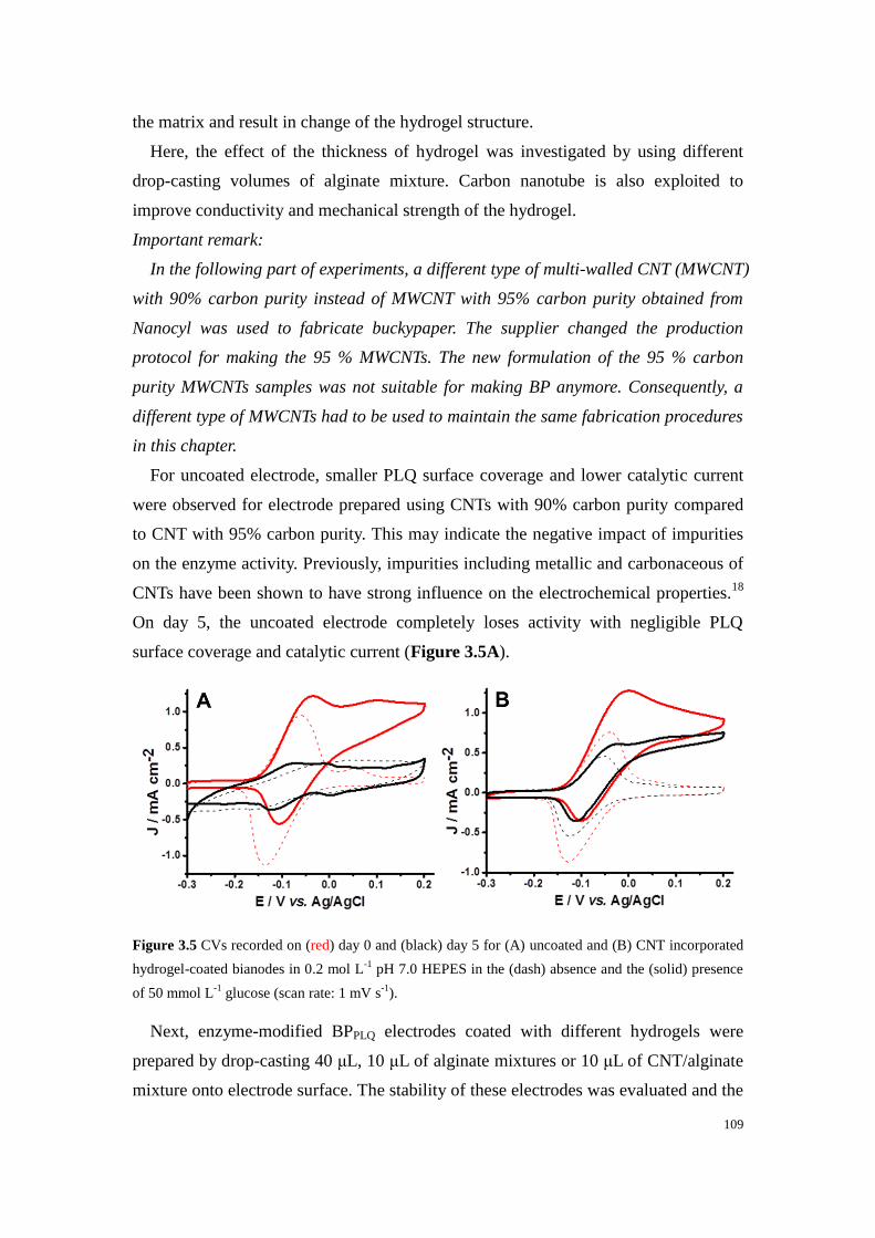
109
the matrix and result in change of the hydrogel structure.
Here, the effect of the thickness of hydrogel was investigated by using different
drop-casting volumes of alginate mixture. Carbon nanotube is also exploited to
improve conductivity and mechanical strength of the hydrogel.
Important remark:
In the following part of experiments, a different type of multi-walled CNT (MWCNT)
with 90% carbon purity instead of MWCNT with 95% carbon purity obtained from
Nanocyl was used to fabricate buckypaper. The supplier changed the production
protocol for making the 95 % MWCNTs. The new formulation of the 95 % carbon
purity MWCNTs samples was not suitable for making BP anymore. Consequently, a
different type of MWCNTs had to be used to maintain the same fabrication procedures
in this chapter.
For uncoated electrode, smaller PLQ surface coverage and lower catalytic current
were observed for electrode prepared using CNTs with 90% carbon purity compared
to CNT with 95% carbon purity. This may indicate the negative impact of impurities
on the enzyme activity. Previously, impurities including metallic and carbonaceous of
CNTs have been shown to have strong influence on the electrochemical properties.18
On day 5, the uncoated electrode completely loses activity with negligible PLQ
surface coverage and catalytic current (Figure 3.5A).
Figure 3.5 CVs recorded on (red) day 0 and (black) day 5 for (A) uncoated and (B) CNT incorporated
hydrogel-coated bianodes in 0.2 mol L-1
pH 7.0 HEPES in the (dash) absence and the (solid) presence
of 50 mmol L-1
glucose (scan rate: 1 mV s-1
).
Next, enzyme-modified BPPLQ electrodes coated with different hydrogels were
prepared by drop-casting 40 μL, 10 μL of alginate mixtures or 10 μL of CNT/alginate
mixture onto electrode surface. The stability of these electrodes was evaluated and the

110
stability data obtained from CVs are summarized in Table 3.2. All three types of
hydrogel coating lead to smaller catalytic currents due to diffusion barrier. Among
them, the electrode coated with 10 μL of alginate mixtures presents the highest
catalytic current on day 1, which is expected as diffusion is faster for thinner hydrogel.
After 5 days of storage, for electrodes coated with 40 μL or 10 μL of alginate mixtures,
less than 30% of the initial catalytic currents remain. The low stability may indicate
that the hydrogel is not effective in preventing enzyme leakage from electrode
surface.
The best performing bioelectrode on day 5 is the one coated with 10 μL of
CNT/alginate mixture (Figure 3.5B). CNTs have been widely used to fabricate
CNT/polymer composite electrodes in various research fields due to their excellent
electronic and mechanical properties.19–21
As shown in Table 3.2, similar PLQ surface
coverage was achieved on day 5 for the three hydrogel-coated electrodes while higher
catalytic current was obtained for the electrode coated with CNT/alginate mixture (67 %
of residual activity). This could be explained by the improved conductivity and
mechanical strength of the hydrogel. More detailed physicochemical studies are
shown in the following section.
Table 3.2 Electrochemical and catalytic parameters for uncoated BPPLQ-GDH electrodes and
BPPLQ-GDH coated with different hydrogel configurations recorded on day 0 and day 5 (MWCNTs
with 90 % carbon purity are used here).
Electrode[a]
Day ΓPLQ / 10
-7 mol
cm-2
Relative stability Jcat
[b] / μA cm
-2 Relative stability
BPPLQ-GDH
0 3.0 ± 1.1 100% 1120 ± 250 100%
(7) 5 0.2 ± 0.2 6% 60 ± 90 6%
40uL gel
0 3.0 ± 0.9 100% 660 ± 180 100%
(3)
5 1.1 ± 0.6 35% 180 ± 90 27%
10uL gel
0 3.9 ± 0.2 100% 940 ± 70 100%
(2)
5 1.1 ± 0.2 28% 210 ± 50 23%
10uL gel with
CNT
0 3.1 ± 0.7 100% 650 ± 210 100%
(6)
5 1.2 ± 0.6 38% 430 ± 170 67%
[a] Electrode fabricated using CNTs with 90% carbon purity; [b] Jcat background subtracted at 0.2 V; calculated using the
geometric surface area of BP electrodes (Ø = 6 mm). The number in brackets corresponds to the number of samples tested

111
3.3.2.2 Characterization of the bioelectrode with optimized hydrogel coating
Figure 3.6 shows the optical images for the CNT incorporated hydrogel-coated
electrode in wet and dry conditions. Optical microscopy is chosen as a simple method
to probe the presence of the hydrogel on the electrode surface. A hydrophilic porous
network of hydrogel is formed when fully hydrated.
Figure 3.6 Optical images of the CNT incorporated hydrogel-coated bioanode in (left) wet and (right)
dry conditions.
Figure 3.7 (A) Schematic representation of the CNT incorporated hydrogel-coated bioanode (yellow
layer: enzyme solution, blue layer: CNT/hydrogel coating); (B) representative CVs of (black) uncoated
and (blue) CNT incorporated hydrogel-coated bianodes in 0.2 mol L-1
pH 7.0 HEPES in the (dash)
absence and the (solid) presence of 50 mmol L-1
glucose (scan rate: 1 mV s-1
); (C) chronoamperograms
recorded at (black) uncoated and (blue) CNT incorporated hydrogel-coated bianodes at Eapp= 0.2 V vs.

112
Ag/AgCl at different glucose concentrations in Ar saturated HEPES buffer pH 7.0 at 150 rpm; (D)
plots of average current density obtained for different glucose concentrations recorded at (black)
uncoated and (blue) CNT incorporated hydrogel-coated bianodes.
The same cyclic voltammetry and chronoamperometry procedures were used to
characterize the catalytic performance of the uncoated and hydrogel-coated bioanode
(Figure 3.7). Longer response time in CAs shows the presence of diffusion barrier. In
terms of catalytic current density, the uncoated bioanodes reached 1120 ± 250 μA cm-2
at 0.2 V while the hydrogel-coated electrodes delivered 650 ± 210 μA cm-2
. The
similar trend in electrochemical behavior confirms the versatility of this approach to
prepare hydrogel-coated bioelectrodes.
Continuous operation stability of bioelectrodes was investigated by performing
chronoamperometry measurement at 0.2 V for 16 h in glucose solution. The catalytic
current of uncoated electrode decreased to 30% of its initial value in 3 h and
continued to decrease to 10% in the following 13 h (Figure 3.8A) In contrast, the
hydrogel-coated electrode still delivered current density of 490 μA cm-2
after 16 h
(~63% of its initial value). The evolution of PLQ surface coverage and catalytic
current before and after 16 h of operation were recorded using cyclic voltammetry
(Figure 3.8B and 3.8C). These results indicate that the presence of a CNT
incorporated hydrogel allows for a better storage and operational stability of
bioelectrode.
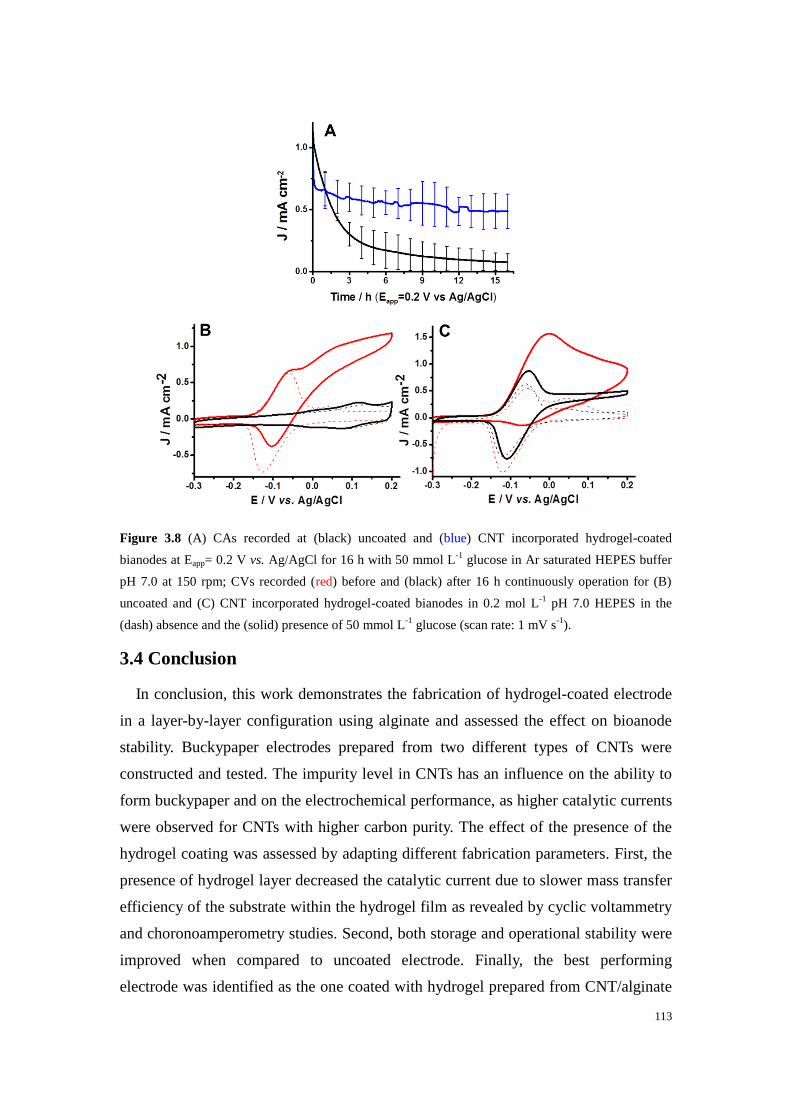
113
Figure 3.8 (A) CAs recorded at (black) uncoated and (blue) CNT incorporated hydrogel-coated
bianodes at Eapp= 0.2 V vs. Ag/AgCl for 16 h with 50 mmol L-1
glucose in Ar saturated HEPES buffer
pH 7.0 at 150 rpm; CVs recorded (red) before and (black) after 16 h continuously operation for (B)
uncoated and (C) CNT incorporated hydrogel-coated bianodes in 0.2 mol L-1
pH 7.0 HEPES in the
(dash) absence and the (solid) presence of 50 mmol L-1
glucose (scan rate: 1 mV s-1
).
3.4 Conclusion
In conclusion, this work demonstrates the fabrication of hydrogel-coated electrode
in a layer-by-layer configuration using alginate and assessed the effect on bioanode
stability. Buckypaper electrodes prepared from two different types of CNTs were
constructed and tested. The impurity level in CNTs has an influence on the ability to
form buckypaper and on the electrochemical performance, as higher catalytic currents
were observed for CNTs with higher carbon purity. The effect of the presence of the
hydrogel coating was assessed by adapting different fabrication parameters. First, the
presence of hydrogel layer decreased the catalytic current due to slower mass transfer
efficiency of the substrate within the hydrogel film as revealed by cyclic voltammetry
and choronoamperometry studies. Second, both storage and operational stability were
improved when compared to uncoated electrode. Finally, the best performing
electrode was identified as the one coated with hydrogel prepared from CNT/alginate

114
mixture, retaining 67% of its catalytic current after 5 days of storage or 63% after 16
h of continuous operation at 0.2 V. In the future work, instead of commercial alginate
used in work, it can be envisioned to use chemically modified alginate with specific
molecule to provide suitable anchor point (i.e. pyrene) to improve stability of the
hydrogel film on electrode surface.
3.5 Experimental Section
3.5.1 Materials and reagents
N,N-dimethylformamide (DMF, 99.9%), 1,10-phenanthroline-5,6-dione (PLQ,
97%), D-(+)-glucose (≥99.5%), sodium chloride (NaCl, 99.8%), calcium carbonate
(CaCO3, 99.0%), calcium chloride dihydrate (CaCl2·2H2O, 99.9%),
D-glucono-δ-lactone (GDL), HEPES, sodium hydroxide (NaOH, pellet) were
purchased from Sigma-Aldrich. Alginic acid sodium salt was obtained from Fluka.
Flavin adenine dinucleotide-dependent glucose dehydrogenase (FAD-GDH, 1150 U
mg-1
solid) from Aspergillus sp. was purchased from Sekisui Diagnostics (UK). Two
different types of multi-walled carbon nanotubes MWCNTs (Ø = 9.5 nm, 1.5 μm
length, ≥95% purity and Ø = 9.5 nm, 1.5 μm length, ≥90% purity) were obtained
from Nanocyl. HEPES buffer used for electrochemical measurements contained 0.2
mol L-1
HEPES and 0.1 mol L-1
NaCl and was adjusted to pH 7.0 using NaOH pellets.
Ca/HEPES Buffer solution for electrode storage was supplemented with 2.5 mmol L-1
CaCl2·2H2O. Deionized (dI) water (18 MΩ) was obtained from a Millipore Ultrapure
system and used to prepare solutions.
3.5.2 Preparation of FAD-GDH modified buckypaper bioanodes
The buckypaper bioélectrodes were prepared according to the procedure reported in
our previous work.1 In brief, 1 mg mL
-1 of MWCNT (95% or 90% carbon purity)
suspension was prepared in DMF and sonicated for 30 min. PLQ was dissolved in a
minimum volume of DMF and added to MWCNT suspension to give a 2 mmol L-1
final concentration, followed by 30 min of sonication. 66 mL of the homogenous
suspension was then filtrated through a PTFE membrane using a diaphragm pump.
The following rinsing and drying procedures were the same as those described in
chapter 2 (section 2.5.3.1).
For enzyme modification, BP was first cut into individual disk electrodes (Ø = 6

115
mm). FAD-GDH was immobilized by drop-casting 54 µL of 3 mg mL-1
FAD-GDH in
HEPES buffer onto the electrode surface and leaving the enzyme to adsorb overnight
at 4 °C.
3.5.3 Preparation of alginate hydrogel-coated bioanodes
Alginate (Alg) mixture was prepared by adding sodium alginate and calcium
carbonate in dI water to give a final concentration of 20 mg mL-1
and 80 mmol L-1
,
respectively. For CNT incorporated hydrogel, MWCNTs were also added to give a
concentration of 2 mg mL-1
. The mixture was left to stir overnight to obtain a
homogeneous dispersion.
To prepare hydrogel-coated electrode in “layer-by-layer” configuration, various
volumes (10 and 40 μL) of Alg/CaCO3 mixture were drop-casted onto the
enzyme-modified electrode. The electrode was allowed to dry in air, and then the
same volume of 160 mmol L-1
of GDL solution was added to the electrode surface.
The electrode was then left overnight at 4 °C to allow hydrogel formation. Electrical
connection was realized by attaching an electrical wire to the back side using carbon
paste and then sealed with silicone paste.
3.5.4 Optical microscopy
Optical images of the electrodes were taken in wet and dry conditions. The
electrode was hydrated with dI water and left in air until fully dried for the wet
condition and dry condition, respectively. Optical images were obtained using a
Keyence VK-X200 microscope at 10x magnification.
3.5.5 Electrochemical characterization
Electrochemical studies were performed at room temperature on an Eco Chemie
Autolab PGSTAT 100 potentiostat with Nova 2.0 software. The three-electrode system
consisted of a BP electrode as the working electrode, a Ag/AgCl (KClsat) as the
reference electrode, and a platinum wire as the auxiliary electrode. All potentials in
this chapter are referred to Ag/AgCl unless otherwise stated. Cyclic voltammetry was
performed at a scan rate of 1 mV s-1
. For the evaluation of the bioanode stability,
cyclic voltammetry was performed periodically. Before electrochemical
measurements, the electrode is incubated in dI water for 1h to fully hydrate the

116
electrode and remove loosely bound enzymes. After measurements, electrode was
stored in Ca/HEPES buffer at 4 °C.
PLQ surface coverage was calculated by integration of the cathodic peaks of CVs
recorded in the absence of glucose, according to Equation 2.2. The current density
values at 0.2 V were obtained by subtracting the background current obtained in the
absence of glucose and reported based on the geometric surface area of the electrode.

117
References
1. Gross, Andrew. J. et al. A High Power Buckypaper Biofuel Cell: Exploiting
1,10-Phenanthroline-5,6-dione with FAD-Dependent Dehydrogenase for Catalytically-Powerful
Glucose Oxidation. ACS Catal. 4408–4416 (2017) doi:10.1021/acscatal.7b00738.
2. Joung, Y.-H. Development of Implantable Medical Devices: From an Engineering Perspective.
Int Neurourol J 17, 98–106 (2013).
3. Mano, N., Mao, F. & Heller, A. Characteristics of a Miniature Compartment-less Glucose−O2
Biofuel Cell and Its Operation in a Living Plant. J. Am. Chem. Soc. 125, 6588–6594 (2003).
4. Cinquin, P. et al. A Glucose BioFuel Cell Implanted in Rats. PLOS ONE 5, e10476 (2010).
5. J. Moehlenbrock, M. & D. Minteer, S. Extended lifetime biofuel cells. Chemical Society Reviews
37, 1188–1196 (2008).
6. Kowalewska, B. & Jakubow, K. The impact of immobilization process on the electrochemical
performance, bioactivity and conformation of glucose oxidase enzyme. Sensors and Actuators B:
Chemical 238, 852–861 (2017).
7. Tsujimura, S., Murata, K. & Akatsuka, W. Exceptionally High Glucose Current on a
Hierarchically Structured Porous Carbon Electrode with ‘Wired’ Flavin Adenine
Dinucleotide-Dependent Glucose Dehydrogenase. J. Am. Chem. Soc. 136, 14432–14437 (2014).
8. Rengaraj, S., Kavanagh, P. & Leech, D. A comparison of redox polymer and enzyme
co-immobilization on carbon electrodes to provide membrane-less glucose/O2 enzymatic fuel
cells with improved power output and stability. Biosensors and Bioelectronics 30, 294–299
(2011).
9. Reuillard, B. et al. High power enzymatic biofuel cell based on naphthoquinone-mediated
oxidation of glucose by glucose oxidase in a carbon nanotube 3D matrix. Physical Chemistry
Chemical Physics 15, 4892 (2013).
10. Xiao, X., Ó Conghaile, P., Leech, D. & Magner, E. Use of polymer coatings to enhance the
response of redox-polymer-mediated electrodes. ChemElectroChem (2018)
doi:10.1002/celc.201800983.
11. El Ichi-Ribault, S. et al. Laccase-based biocathodes: Comparison of chitosan and Nafion.
Analytica Chimica Acta 937, 43–52 (2016).
12. Jain, D. et al. Low-Molecular-Weight Hydrogels as New Supramolecular Materials for
Bioelectrochemical Interfaces. ACS Appl. Mater. Interfaces 9, 1093–1098 (2017).
13. Aslani, P. & Kennedy, R. A. Studies on diffusion in alginate gels. I. Effect of cross-linking with
calcium or zinc ions on diffusion of acetaminophen. Journal of Controlled Release 42, 75–82
(1996).
14. Draget, K. I., Skjåk-Bræk, G. & Smidsrød, O. Alginate based new materials. International
Journal of Biological Macromolecules 21, 47–55 (1997).
15. Pereira, R. et al. Development of novel alginate based hydrogel films for wound healing
applications. International Journal of Biological Macromolecules 52, 221–230 (2013).
16. Kuo, C. K. & Ma, P. X. Ionically crosslinked alginate hydrogels as sca!olds for tissue
engineering: Part 1. Structure, gelation rate and mechanical properties. 11 (2001).

118
17. Esser, E. & Tessmar, J. K. V. Preparation of well-defined calcium cross-linked alginate films for
the prevention of surgical adhesions. J. Biomed. Mater. Res. 101B, 826–839 (2013).
18. Pumera, M., Ambrosi, A. & Chng, E. L. K. Impurities in graphenes and carbon nanotubes and
their influence on the redox properties. Chemical Science 3, 3347 (2012).
19. Wang, J., Dai, J. & Yarlagadda, T. Carbon Nanotube−Conducting-Polymer Composite Nanowires.
Langmuir 21, 9–12 (2005).
20. Sivakkumar, S. R., Ko, J. M., Kim, D. Y., Kim, B. C. & Wallace, G. G. Performance evaluation
of CNT/polypyrrole/MnO2 composite electrodes for electrochemical capacitors. Electrochimica
Acta 52, 7377–7385 (2007).
21. He, L., Lin, D., Wang, Y., Xiao, Y. & Che, J. Electroactive SWNT/PEGDA hybrid hydrogel
coating for bio-electrode interface. Colloids and Surfaces B: Biointerfaces 87, 273–279 (2011).

119
Chapter 4:
Stretchable and flexible
buckypaper-based lactate
biofuel for wearable
electronics

120
121
Chapter 4 Stretchable and flexible buckypaper-based lactate
biofuel cell for wearable electronics
Résumé
Comme indiqué dans le premier chapitre (section 1.4.2), les biopiles enzymatiques
sont très prometteuses en tant que source d'alimentation pour les dispositifs
électroniques portables non invasifs dans le domaine médical en raison du niveau
raisonnable de lactate présent dans la sueur. Pour répondre à l'exigence d'un dispositif
portable, la biopile doit être flexible et étirable afin de résister à la tension causée par
les mouvements du corps. Les biopiles à carburants enzymatiques à base de papier de
carbone sont idéales pour les applications portables. Les propriétés exceptionnelles
des bioélectrodes à base de buckypaper pour l'oxydation du glucose et la réduction de
l'oxygène ont été démontrées dans les chapitres précédents. Dans ce chapitre, la
flexibilité du papier a été utilisée pour fabriquer une biopile à combustible au lactate
extensible et flexible.
Il existe un intérêt croissant pour les dispositifs électroniques portables, en
particulier ceux destinés aux applications de contrôle de la condition physique et de la
santé, telles que la surveillance du mouvement,1 la détection de signaux
physicochimiques2,3
et la cicatrisation des plaies.4 Le développement rapide de
dispositifs portables nécessite le développement de sources d'énergie pouvant être
facilement intégrées au corps humain. Malgré les énormes progrès récents des
dispositifs portables, la plupart de ces dispositifs sont toujours alimentés par des
batteries rigides et volumineuses qui posent des problèmes environnementaux. Les
biocarburants enzymatiques (EFC), qui reposent sur les oxydoréductases pour
convertir bioélectrocatalytiquement les biocarburants présents dans les fluides
corporels humains, ont été considérés comme des candidats prometteurs pour
l’alimentation des appareils électroniques portables de prochaine génération.5,6
Les
substrats ont été largement étudiés en raison de la facilité d'accès au lactate dans la
sueur humaine et de leur intégration facile dans l'électronique portable.7–9
La
puissance des EFC et leur flexibilité sont deux défis majeurs dans ce domaine, compte
tenu de la concentration limitée de lactate dans la sueur et de la contrainte externe
imposée par les mouvements du corps. Pour surmonter ces problèmes, il est essentiel
de développer des matériaux d'électrode capables d'améliorer l'efficacité du transfert
d'électron enzymatique et d'offrir flexibilité et conformité lorsque le dispositif est

122
placé à même la peau.
Les nanotubes de carbone (CNTs) ont été largement utilisés pour fabriquer des
bioélectrodes en raison de leurs propriétés électroniques exceptionnelles, de leur
inertie électrochimique et de leur grande surface spécifique.10
Pour fabriquer des
électrodes destinées à des applications pratiques sur des cellules biocarburant, les
CNTs sont souvent formés en encres,11
pastilles,8,12
papiers,13,14
et fibres.15
Les
électrodes CNT sérigraphiées ont été populaires pour les EFCs portables; cependant,
ce type d'électrode nécessite un mélange avec un liant élastomère, qui bloque
inévitablement la surface active des CNTs et compromet le courant électrocatalytique
(d'où les performances de puissance moindres).11,16-18
Les pastilles CNTs, utilisées
dans la première génération d’électrodes pour EFCs implantables, ont plusieurs
millimètres d'épaisseur et sont donc volumineuses, ont un faible transfert de masse et
ont tendance à être fragiles.19,20
Dans la présente étude, on a choisi du papier-buckypaper (BP) comme matériau
d'électrode. Le BP est un matériau autosupporté et conducteur semblable à du papier,
comprenant un réseau de CNTs enchevêtrés.21
Plus tôt, une biopile lactate/O2 avec des
électrodes en BP a été explorée dans les larmes synthétiques.22
Très récemment, une
bioanode à base buckypaper pour l’oxydation du lactate a été couplée à une
photocathode a également été rapportée.23
Toutefois, la densité de puissance des deux
dispositifs était plutôt faible et aucune extensibilité n'a été démontrée. Dans les deux
systèmes, des BPs fabriqués à base de nanotubes de carbone à parois multiples
(MWCNTs) de source commerciale ont été utilisés comme matériau d'électrode.
Inversement, dans ce chapitre, les MWCNTs BP fabriqués en laboratoire ont été
fabriqués à l'aide d'une méthode de filtration sous vide destinée à être utilisée comme
matériau d'électrode. Le résultat précédent décrit au chapitre 2 montre que le BP
fabriqué en laboratoire est supérieur au BP commercial en tant que matrice
d'immobilisation de la bilirubine oxydase (BOx), qui montre un courant catalytique
plus élevé pour la réaction de réduction d'oxygène (ORR). Une nouvelle classe de BP
flexibles fabriqués en laboratoire a été développée dans notre groupe sur la base de la
réticulation des CNTs avec des polymères linéaires de polynorbornène comprenant
des groupes pyrènes. Le BP polynorbornène-pyrène est une excellente matrice pour le
médiateur redox et l'immobilisation enzymatique.14,24,25
Cependant, le manque
d'extensibilité intrinsèque a entravé l'application des BP dans les EFC cutanées.
Dans ce chapitre, une EFC offrant de bonnes performance, possédant des propriétés

123
extensible, flexible et portable est présentée. Grâce à une combinaison unique
d'électrodes de BP hautement conductrices et catalytiques et d'un support d’électrode
à structure extensible, il a été possible de récupérer l'énergie directement de la
transpiration d’un individu. Pour répondre à l'exigence des dispositifs portables de
supporter des mouvements rigoureux et des déformations pendant l'exercice physique,
une extensibilité "2 degrés" (c'est-à-dire une extensibilité structurelle et une
extensibilité intrinsèque du matériau) a été réalisée en combinant une formule d'encre
extensible avec une architecture "island-bridge".11
Les électrodes de l'appareil ont été
séparées en "îlots" solidaires du substrat et en "ponts" d'interconnexion en forme de
serpentin, souples et extensibles, qui peuvent se dérouler sous contrainte.11,26
Lorsqu'une contrainte externe est appliquée, la contrainte est répartie sur les "ponts"
flexibles autour des "îlots" durs non extensibles, maintenant ainsi une résistance
électrique stable. C'est pourquoi nous avons opté pour une interconnexion
autoportante à boucles, adoptée dans le cadre de nos travaux précédents, afin
d'accroître encore davantage sa souplesse et sa conductivité.26

124
Chapter 4 Stretchable and flexible buckypaper-based lactate
biofuel cell for wearable electronics
This chapter is based on the following manuscript-
Xiaohong Chen, Lu Yin, Jian Lv, Andrew J. Gross, Minh Le, Nathaniel Georg
Gutierrez, Yang Li, Itthipon Jeerapan, Fabien Giroud, Anastasiia Berezovska, Rachel
K. O’Reilly, Sheng Xu, Serge Cosnier, Joseph Wang
Adv. Funct. Mater. 2019, 1905785
4.1 Abstract
As discussed in the first chapter (section 1.4.2), enzymatic biofuel cell is a
promising candidate as power source for wearable electronic devices due to the
reasonable level of lactate present in sweat. To meet the requirement of wearable
device, the biofuel cell needs to be flexible and stretchable in order to withstand the
strain caused by body movement. Enzymatic biofuel cells based on buckypaper are
ideal for wearable applications. The exceptional properties of buckypaper based
bioelectrodes for glucose oxidation and oxygen reduction have been demonstrated in
previous chapters. In this chapter, the flexibility of buckypaper was exploited to
fabricate a stretchable and flexible lactate biofuel cell.
4.2 Introduction
There is a continuously growing interest for wearable electronic devices,
particularly, devices for fitness and health monitoring applications such as motion
monitoring,1 physicochemical signal sensing,
2,3 and wound healing.
4 The rapid
development of wearable devices demands the development of efficient reliable and
conformal power sources that can be easily integrated onto the human body. Despite
the tremendous recent progress of wearable devices, most of these devices are still
powered by rigid and bulky batteries which pose environmental concerns. Enzymatic
biofuel cells (EFCs), which rely on oxidoreductases to bioelectrocatalytically convert
biofuels present in human body fluids, have been considered as promising candidates
for powering next generation wearable electronic devices.5,6
Specifically, epidermal
skin-worn EFCs that use lactate as the substrate have been widely studied given the
easy access to lactate in human sweat and their facile integration with wearable
electronics.7–9
The power output of EFCs and their flexibility are two major
125
challenges in this field considering the limited concentration of lactate in sweat and
the external strain imposed from body movements. To overcome these issues, it is
essential to develop electrode materials that can enhance enzyme electron transfer
efficiency and provide flexibility and conformity when the device is mounted on the
skin.
Carbon nanotubes (CNTs) have been widely used to construct bioelectrodes given
their exceptional electronic properties, electrochemical inertness and high surface
area.10
To construct electrodes for practical biofuel cell applications, CNTs are often
shaped into inks,11
pellets,8,12
papers,13,14
and fibers.15
Screen-printed CNT electrodes
have been popular for wearable biofuel cells; however, this type of electrode requires
mixing with an elastomeric binder, which inevitably blocks the active surface of
CNTs and compromises electrocatalytic current (hence power performance).11,16–18
CNT pellets, used in the first generation of implantable biofuel cells, are several
millimeters thick and are therefore bulky, have slow mass transfer efficiency, and tend
to be fragile.19,20
In the present study, buckypaper (BP) was chosen as the electrode material. BP is a
self-supported and conductive paper-like material comprising a network of entangled
CNTs.21
Previously, a buckypaper-based lactate/O2 EFC was explored in synthetic
tears.22
Very recently, a buckypaper-based lactate bioanode coupled with a
photocathode was also reported.23
However, the power density of both devices was
rather low and no stretchability was demonstrated. In both systems, multi-walled
carbon nanotubes (MWCNTs) BP from a commercial source were utilized as the
electrode material. In contrast, in this chapter, lab-made MWCNTs BP using a
vacuum filtration method was fabricated for use as the electrode material. The
previous result described in chapter 2 shows that lab-made MWCNTs BP is superior
to commercial MWCNTs BP as an immobilization matrix for bilirubin oxidase (BOx),
which shows a higher catalytic current for the oxygen reduction reaction (ORR). A
new class of lab-made flexible BPs has been developed in our group based on the
cross-linking of CNTs with polynorbornene linear polymers comprising pyrene
groups. The polynorbornene-pyrene BP is an excellent matrix for redox mediator and
enzyme immobilization.14,24,25
However, the lack of intrinsic stretchability has
impeded the application of BPs in epidermal EFCs.
In this chapter, a high power, stretchable, flexible and wearable EFC is presented.
Through a unique combination of highly conductive and catalytic BP electrodes with

126
a structurally stretchable substrate, it is possible to harvest energy directly from
perspiration. To meet the requirement of wearable devices to endure rigorous
movements and deformation during human exercise, a “2-degree” stretchability (i.e.
structural stretchability and material intrinsic stretchability) was realized by
combining a stretchable ink formula with an “island-bridge” architecture.11
The
electrodes of the device were separated into “islands”, which are firmly bonded to the
substrate, along with serpentine-shaped interconnecting “bridges”, which are soft and
stretchable and can unwind under stress.11,26
When external strain is applied, the stress
is distributed to the flexible “bridges” around the hard non-stretchable “islands”,
therefore maintaining electrical resistance stability. Herein, a free-standing,
buckling-enabled interconnect design, adopted from our previous work, was chosen to
further enhance its flexibility and conductivity.26
4.3 Results and discussion
4.3.1 Design of the EFC
As illustrated in Figure 4.1, the stretchable and flexible wearable EFCs are
fabricated by integrating buckypaper-based electrodes and stretchable current
collectors. The stretchable substrate is fabricated via a high-throughput and low-cost
screen-printing method. The carbon-based electrode “islands” are interconnected by
high-conductivity silver composite “bridges” in a serpentine shape. A “skeleton” layer
composed of polystyrene (PS) and styrene ethylene butylene styrene (SEBS) is added
below the carbon islands to enhance their mechanical stability, and a water-soluble
sacrificial layer is added below the serpentine interconnects to allow their separation
from the substrate. A flexible polymer is printed on both sides of the silver
interconnects to avoid the direct contact of silver and the electrolyte. The printed
sacrificial layer is dissolved in water to enable buckling of the serpentine structures
during deformation. To complete the assembly of the skin patch illustrated in Figure
4.1A, pre-cut anodic and cathodic BP electrodes were thereafter attached to the
carbon islands. A thin sheet of phosphate buffer solution-polyvinyl alcohol (PB-PVA)
hydrogel was added as electrolyte and a sweat reservoir was applied onto the
electrodes. The fabrication process is illustrated in detail in Figure 4.2.
The printed patch can be attached to the human epidermis in a wide range of
locations where perspiration is usually observed (e.g. arm, neck, chest, back) while

127
maintaining high conformity (Figure 4.1). The system has been designed to endure
mechanical strains caused by bodily movements. Endowed by the advantageous
“island-bridge” structure, the EFC patch is highly flexible and stretchable (Figure
4.1B) and can endure severe bending (Figure 4.1C). The serpentine structures
accommodate most of the stress. The patch is activated once perspiration takes place a
few minutes after exercise, when the lactate (originating from the sweat) is absorbed
into the hydrogel electrolyte and permeates to the bioelectrodes. The reaction
mechanism is illustrated in Figure 4.1D. The bioanodes consist of a
pyrene-polynorbornene functionalized BP with immobilized lactate oxidase (LOx)
from microorganisms and 1,4-naphthoquinone (1,4-NQ) as the electron transfer
mediator for mediated bioelectrocatalytic oxidation of lactate into pyruvate. The
biocathodes consist of BPs with immobilized bilirubin oxidase (BOx) from
Myrothecium sp. to catalyze the reduction of oxygen. For the cathode, BP is modified
with protoporphyrin IX (PPIX) molecules which can orientate the enzyme
preferentially through “lock-key” interaction between the substrate pocket near the T1
center of BOx and PPIX to facilitate direct electron transfer with the CNTs.14,27
The
current and voltage generated from the anodic and cathodic reactions can thereafter be
exploited to power various electronics in a biofuel cell configuration.
Figure 4.1 (A) Photograph of the stretchable EFC device on a human arm, (zoom) schematic
illustration of the skin-mountable wearable EFC device; (B, C) Photographs of the EFC under
stretching and bending, respectively; (D) Schematics of the redox energy generation from sweat lactate
oxidation at the anode and O2 reduction at the cathode by EFC.

128
Figure 4.2 Schematic illustration of (A) the screen-printing process; (B) designed patterns for different
screen-printing layer; (C) Zoom of the interconnect “bridge” and electrode “island” structure (red
squares in (B)).
4.3.2 Performance of the EFC
The morphology of BP functionalized with the pyrene-polynorbornene
homopolymer was characterized using scanning electrode microscopy (SEM) and
revealed a homogenous mesoporous structure of entangled CNT bundles (Figure
4.3A). The electrochemical performance of the biocathodes and bioanodes were
evaluated individually using a three-electrode set-up with a platinum counter
electrode and an Ag/AgCl (3M KCl) reference electrode. Figure 4.3B shows overlaid
linear sweep voltammograms (LSVs) recorded for the bioanode in the presence of 0
and 15 mmol L-1
lactate in 0.5 mol L-1
phosphate buffered solution (PB, pH 7.4),
respectively. In the absence of lactate, the faradaic current corresponds to oxidation of
the 1.4-naphthohydroquinone. Upon addition of lactate, the mediated
bioelectrocatalytic current of lactate oxidation starts to flow and results in a current
density of 1.3 mA cm-2
at 0.2 V. The current did not further improve when lactate
concentration was increased to 20 mmol L-1
(data not shown), which indicates that the
catalytic current is limited by the amount of enzymes immobilized on electrode
surface. Figure 4.3C shows LSVs for the biocathode tested in buffer with
air-saturated O2. The oxygen reduction current starts to increase dramatically at a
potential close to 0.5 V, reaching a maximum current density of -1.5 mA cm-2
at 0 V.
The presence of lactate did not affect the performance of the BOx bioelectrode as the
onset potential for ORR and the limiting current were unchanged. The high onset
potential and steep oxygen reduction reaction slope indicate a more efficient direct
electron transfer between the T1 center of BOx and the CNTs. The excellent
performance is in agreement with other reported protoporphyrin-modified
biocathodes.14,27

129
The power performance of the EFC was investigated using a unit cell device
comprising a single biocathode and a single bioanode, as depicted in Figure 4.1D. As
low oxygen concentration can limit the power of the EFC, the area of the biocathode
was designed to be two times larger than the bioanode to ensure that the EFC
performance was not limited by the cathode. LSVs were recorded from the open
circuit voltage (OCV) to 0.01 V (near short circuit) in different lactate concentrations.
The power-voltage curves are shown in Figure 4.3D. Both the OCV and peak power
density increased with increasing lactate concentrations, reaching saturation at 10
mmol L-1
lactate with a OCV value of 0.74 V. A maximum power density of 0.5 mW
cm-2
was recorded at 0.55 V in 10 mmol L-1
lactate. However, for subsequent
characterization experiments, 15 mmol L-1
lactate was used to match the average
lactate concentration in sweat.28
Although the power density herein is lower than the
maximum value of ca 1.2 mW cm-2
reported in the literature, where a battery type
silver oxide cathode was used.8 This work presents the use of a fully enzymatic fuel
cell with an enzymatic biocathode for oxygen reduction. The power performance was
compared with other reported work in the literatures and is summarized in Table 4.1.
The power performance stability of the EFC was investigated periodically by
performing linear sweep voltammetry in 15 mmol L-1
lactate over an extended period
of 48 hours (Figure 4.3E). As shown in Figure 4.3F, the power density at 0.55 V
decreases only by 16 % after 48 hours. Controlled experiments were conducted on
EFCs fabricated by immobilizing enzymes on screen-printed current collectors and
CNT ink9 electrodes, respectively. The power performance of the controlled groups
compared to the BP-based EFC was shown in Figure 4.4. For these two alternative
systems, the power performance in 15 mmol L-1
lactate are negligible compared to the
BP-based EFC, highlighting that the excellent performance of EFC originates from
the BPs used in this work.
Table 4.1 Performance of wearable lactate-based EFCs reported in the literatures
Year Anode Cathode OCV/ V
Power
density/
µW cm-2
Electrode
Material Reference
2014 LOx Pt 0.7 100 CNT ink Jia et al.17
2015 NADLDH BOx 0.41 8 Buckypaper Reid et al.22
2017 LOx Ag2O 0.5 1000 CNT pellet Bandodkar et al.8
2019 LOx BOx 0.55 20 Toray carbon Escalone-Villalpando

130
paper et al.29
2019 LOx BOx 0.74 520 Buckypaper This work
Figure 4.3 (A) SEM image of buckypaper functionalized with pyrene-polynorbornene. (B) LSV of the
BP bioanode in the presence of (black) 0 mmol L-1
and (red) 15 mmol L-1
lactate in 0.5 mol L-1
PB
(pH 7.4) at 5 mV s-1
. (C) LSV of the BP biocathode in air-equilibrated buffer with (black) 0 mmol L-1
and (red) 15 mmol L-1
lactate at 5 mV s-1
. (D) The power density versus voltage plots for the
stretchable lactate EFC under different lactate concentrations (0, 5, 10 and 15 mmol L-1
) in 0.5 M PB
(pH 7.4). (E) Plots showing the stability of the stretchable EFC in the presence of 15 mmol L-1
lactate
at different times up to 48 hours. (F) The calculated relative change of power density at 0.55 V over 48
hours, based on the data in (E).
Figure 4.4 Plots of power density versus voltage of (green) stretchable buckypaper EFC and
(left)(blue) screen-printed EFC based on current collector modified with enzymes and (right)(blue)
screen-printed EFC based on CNT ink (formula from reported literature) modified with enzymes.

131
4.3.3 Self-charging behavior of the EFC
The ability of the EFC to function also as a self-powered supercapacitor was
investigated. Figure 4.5A shows cyclic voltammograms (CVs) recorded for the EFC
in the presence of 0 mmol L-1
and 15 mmol L-1
lactate in PB solution. In the absence
of lactate, a quasi-symmetric rectangular shape of the CV curves indicates highly
capacitive behavior, which is expected for high surface area nanostructured carbon
electrodes.12,30
Upon addition of 15 mmol L-1
lactate, the capacitive current increased,
which can be explained by the additional electronic charge loading on the CNT matrix
via the enzymatic oxidation of lactate. The capacitance of the device was further
investigated by performing galvanostatic charge-discharge (GCD) at different
constant current densities between 0 V and 0.8 V. This technique is a more accurate
method to probe the device capability to function as real-world capacitors. GCD
curves and the calculated areal capacitance at different current densities are shown in
Figure 4.6. A high capacitance of 40 mF cm-2
was observed at 0.1 mA cm-2
, which is
comparable to other reported self-charging biosupercapacitors.31,32
It should be noted
that no extra modification of the bioelectrodes was needed, such as manganese oxide
to obtain this capacitive performance.
Figure 4.5 (A) CV of EFC in the presence of (black) 0 mmol L-1
and (red) 15 mmol L-1
lactate in 0.5
mol L-1
PB (pH 7.4) at 50 mV s-1
. (B) Overlay of potential profiles obtained from EFC discharge at 2, 5,
10, 15, 20 and 25 mA cm-2
over 10 ms. (C) Plot of the calculated pulse power density as a function of
the discharge current density. (D) Potential profile of the EFC during a discharge at 5 mA cm-2
at 33 Hz
frequency.
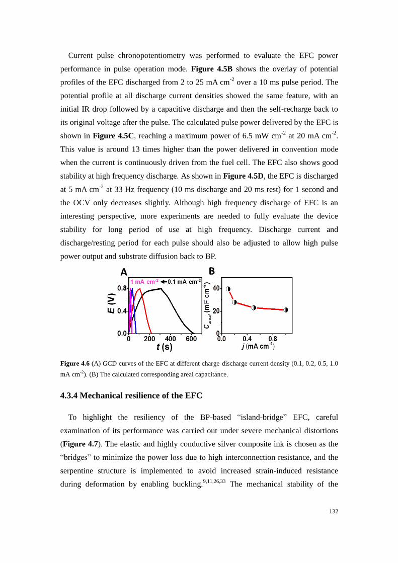
132
Current pulse chronopotentiometry was performed to evaluate the EFC power
performance in pulse operation mode. Figure 4.5B shows the overlay of potential
profiles of the EFC discharged from 2 to 25 mA cm-2
over a 10 ms pulse period. The
potential profile at all discharge current densities showed the same feature, with an
initial IR drop followed by a capacitive discharge and then the self-recharge back to
its original voltage after the pulse. The calculated pulse power delivered by the EFC is
shown in Figure 4.5C, reaching a maximum power of 6.5 mW cm-2
at 20 mA cm-2
.
This value is around 13 times higher than the power delivered in convention mode
when the current is continuously driven from the fuel cell. The EFC also shows good
stability at high frequency discharge. As shown in Figure 4.5D, the EFC is discharged
at 5 mA cm-2
at 33 Hz frequency (10 ms discharge and 20 ms rest) for 1 second and
the OCV only decreases slightly. Although high frequency discharge of EFC is an
interesting perspective, more experiments are needed to fully evaluate the device
stability for long period of use at high frequency. Discharge current and
discharge/resting period for each pulse should also be adjusted to allow high pulse
power output and substrate diffusion back to BP.
Figure 4.6 (A) GCD curves of the EFC at different charge-discharge current density (0.1, 0.2, 0.5, 1.0
mA cm-2
). (B) The calculated corresponding areal capacitance.
4.3.4 Mechanical resilience of the EFC
To highlight the resiliency of the BP-based “island-bridge” EFC, careful
examination of its performance was carried out under severe mechanical distortions
(Figure 4.7). The elastic and highly conductive silver composite ink is chosen as the
“bridges” to minimize the power loss due to high interconnection resistance, and the
serpentine structure is implemented to avoid increased strain-induced resistance
during deformation by enabling buckling.9,11,26,33
The mechanical stability of the

133
buckypaper EFC was evaluated using a stepping-motor controlled biaxial stretching
stage. The printed EFC was stretched repeatedly to 120% of its original size in both x
and y directions (Figure 4.7B). The ohmic resistance of the circuit between the silver
contact on the end of the patch and the central printed carbon electrode was measured
during a 100-cycle stretching test, as shown in Figure 4.7C. The resistance of the
circuit varies less than 1 Ω in each stretching cycle (Figure 4.7C inset), with no trend
of increasing resistance after all of the stretching cycles. The mechanical stability was
further validated by monitoring the discharge current of the EFC under a constant
load. One pair of electrodes was covered in PB-PVA gel electrolyte with 15 mmol L-1
lactate and connected to a 33 kΩ resistor, as shown in Figure 4.7A. The discharge
current exhibited no significant change during 20 cycles of stretching, which further
validates the mechanical stability of the patch as a practical wearable
energy-harvesting device. The durability of the generated power performance was
examined in connection to numerous stretching cycles. LSV scan was performed
every 20 cycles of 20% biaxial stretching. The power density remained highly stable
after 100 cycles of stretching (Figure 4.7E and 4.7F).

134
Figure 4.7 Mechanical resilience studies: Image of the wearable EFC (A) before and (B) after 20%
stretching. (C) Resistance profile obtained during 20% stretching, (inset) zoom of resistance
fluctuations. (D) Current density output profile of the EFC under a 33 kΩ load in PVA gel immersed in
15 mmol L-1
lactate, (inset) zoom of current density fluctuations. (E) Plots of EFC power density
versus voltage under 20% stretching for 0, 20, 40, 60, 80 and 100 cycles in 15 mmol L-1
lactate. (F)
The calculated relative change of power density at 0.55 V over 100 stretching cycles.
4.3.5 On-body power generation
The real-time power output of the wearable buckypaper EFC was tested by
monitoring the current of the circuit (with 510 Ω load) when the volunteer was doing
constant stationary cycling exercise. The power change of the EFC during the whole
process is shown is Figure 4.8A. The power is very low before the volunteer started
to sweat due to the absence of the fuel. After 10 minutes of exercise, perspiration is
formed and visually observed on the subject, which is corroborated by a rapid
increase in the power density of the EFC indicating lactate molecules from the sweat
was transferred to the interface of the LOx bioanode. The highest power density
obtained is around 450 µW after 30 minutes of perspiration, which is an output that is
sufficient to power various wearable devices considering their low power
requirements.34
When the volunteer stopped cycling, a constant drop of power is
observed, probably caused by the insufficient supply of lactate and oxygen dissolved
in the sweat.16
It has to be mentioned that the fuel cell was still able to deliver energy
in absence of exercise as the power was near 100 µW after 15 minutes without new
supply of substrate. The capability of the flexible buckypaper EFC to serve as the
power source for wearable electronic devices was demonstrated by powering a LED
during stationary cycling exercise. The voltage of the EFC was boosted using a
flexible DC-DC converter, as shown in Figure 4.8C, Figure 4.10 and Video S1 and
S2 (see supporting information of DOI: 10.1002/adfm.201905785). Figure 4.8B
illustrates the circuit connection of the patch, the voltage booster, the LED and a
switch which was used to control the “on” and “off” function of the LED. When
connected with the sweat-based EFC, the LED lit up (Figure 4.8E) and its voltage
can reach over 1.4 V both in pulse mode and continuous discharging modes (Figure
4.9), illustrating the feasibility of the voltage boosted buckypaper EFCs to supply
energy for wearable electronics.

135
Figure 4.8 (A) Power output profile under 510 Ω load during an on-body experiment. (B) The circuit
schematics for using the flexible and stretchable epidermal EFC patch to power an LED via a flexible
DC-DC convertor. (C) Image of on-body experiment set up with a EFC mounted on the arm of the
volunteer. (D) and (E) Imagesof the LED switched on and off, respectively.
Figure 4.9 (A) and (B) Voltage output profile under 0.2s pulsed discharge and continuous discharge
during exercise, respectively.

136
Figure 4.10 (A) The circuit diagram and (B) the photo of the prepared flexible voltage boosting circuit.
4.4 Conclusion
In conclusion, a stretchable and wearable enzymatic EFC that harvests energy from
sweat has been created through the combination of a screen-printed current collector
substrate and flexible enzyme-modified polynorbornene-based BPs. During in vitro
experiments, the assembled EFC had a high OCV of 0.74 V and a maximum power
density of 520 µW cm-2
. The stretchability of the device was realized through the
coupling of “island-bridge” architecture and strain-enduring inks. The device was able
to remain its performance stability under multiple stretching cycles. After coupling
with a voltage booster, the BP-based EFC was able to power a commercial LED both
in pulse mode and in continuous mode. We have demonstrated the promising potential
of using BP as high-performance carbon electrode material for epidermal EFC with a
stretchable supporting substrate. Such stretchable skin-worn devices are expected to
contribute to the development of epidermal energy harvesting systems and wearable
A

137
electronics, in general. The reported BFC device still relies on exercises for sweat
generation, which limits its usages for athletic purposes. The lactate (fuel) sweat
concentration, and the hence the generated power, may depend on the specific
individual and its activity. Challenges, such as the availability of biofuels or oxygen,
can be addressed via different strategies such as the use of sweat-inducing chemicals
or replacing the cathode with an air-breathing electrode. Future studies will aim at
improving the biocompatibility, the catalytic performance of each individual
bioelectrode, and further electronics integration along with extensive on-body
operations.
4.5 Experimental section
4.5.1 Materials and reagents
1,4-naphthoquinone (1,4-NQ), protoporphyrin IX (PPIX, ≥95%), bovine serum
albumin (BSA), glutaraldehyde, chitosan, toluene, L(+)-lactic acid, potassium
phosphate dibasic (K2HPO4), potassium phosphate monobasic (KH2PO4), polyvinyl
alcohol (PVA, MW 146 000–186 000 and MW 89 000-98 000), potassium hydroxide
(KOH), ethanol, acetone, acetic acid, N,N-dimethylformamide (DMF, 99.9%) and Ag
flakes (10 μm) were purchased from Sigma-Aldrich. Tetrahydrofuran (THF) was
purchased from EMD Millipore. Hydroxyl-functionalized multi-walled carbon
nanotubes (MWCNT-OHs, Ø = 10–20 nm, 10–30 μm length, >95% purity) were
purchased from Cheap Tubes Inc. Commercial grade multi-walled carbon nanotubes
(MWCNTs, Ø = 9.5 nm, 1.5 μm length, ≥90% purity) for buckypaper fabrication were
purchased from Nanocyl. L-Lactate oxidase (LOx) from Microorganism was
purchased from Toyobo. Bilirubin oxidase (BOx) from Myrothecium sp. was a gift
from Amano Enzyme. Polyurethane (PU, Tecoflex SG-80A) was purchased from
Lubrizol LifeSciences. Polystyene (PS) was obtained from polystyrene foam
packaging material. Styrene Ethylene Butylene Styrene copolymer (SEBS) was
purchased from Kraton. Ecoflex®
00-30 (Smooth-On, Inc. PA.) was prepared by
mixing equal volumes of pre-polymers A and B, provided by the supplier. Perme-roll®
Lite (L34R10) was purchased from Nitto Denko. Carbon paste (C2030519P4) was
purchased from Gwent Group. 0.5 mol L-1
pH 7.4 Potassium phosphate buffer
solution (PB) was prepared from potassium phosphate dibasic and potassium
phosphate monobasic. Ultra-pure deionized water (DI, 18.2 MΩ) was used for all of

138
the aqueous solutions.
4.5.2 Formulations
4.5.2.1 Formulation of the interlayer PU ink
A PU interlayer was used to enhance the adhesion between the EFC and the
substrate. A 12% PU ink was prepared by dissolving the Tecoflex PU beads in THF
and mixed using a vortex machine overnight at room temperature.
4.5.2.2 Formulation of the PS-SEBS backbone polymer ink
3.6 g of polystyrene from packing foam and 0.4 g of SEBS beads were dissolved in
10 mL toluene. The mixture was then mixed using a vortex machine overnight at
room temperature.
4.5.2.3 Formulation of the PVA sacrificial ink.
A water-soluble sacrificial layer ink was prepared by dissolving 1 g of PVA (MW
146 000–186 000) in 5 g of DI water in an 80 ºC water bath.
4.5.2.4 Synthesis of the PB-PVA hydrogel
A 20 wt% PVA (MW 89 000-98 000) solution is prepared by dissolving the PVA in
water in an 80 ºC water bath. A 10 wt% KOH aqueous solution is also prepared and
added to the PVA solution at 1:1 ratio by weight to form the hydrogel precursor. The
hydrogel precursor is left in desiccator under vacuum for 1 day until cross-linked, and
then taken out to then be washed in DI water to remove excess KOH. The washed
hydrogel is soaked in 0.5 mol L-1
(pH 7.4) PB for later use.
4.5.2.5 Formulation of the SEBS insulation ink and Ag-SEBS conductive ink.
The SEBS insulation ink was prepared by dissolving the SEBS beads in toluene
(0.6 g mL-1
). The stretchable conductive ink was prepared by mixing the silver flakes
with the SEBS resin. A 0.4 g mL-1
of SEBS was prepared by dissolving the SEBS
beads in toluene, then the silver flakes was mixed with the SEBS resin with the
weight ratio of 2:1 ratio in a dual asymmetric centrifugal mixer (Flacktek Speedmixer,
DAC 150.1 KV-K, FlackTek, SC, USA) under a speed of 1800 rpm for 5 min. To
enhance the mixing of the ink, Zirconia (YSZ) beads (3 mm, Inframat Advanced
Materials, CT, USA) were also added.

139
4.5.3 Procedures
4.5.3.1 “Island-bridge” electrode fabrication
A thin layer of Ecoflex was printed on the adhesive side of a Perme-Roll® Lite film
and cured at 65 oC for 10 min to form the low elastic modulus substrate. Each layer
depicted in Figure 4.2 was screen printed on the non-adhesive side of the elastic
substrate using an MPM-SPM semi-automatic screen printer (Speedline Technologies,
Franklin, MA, USA). A 100 μm-thick stainless-steel printing stencil was designed in
AutoCAD (Autodesk, USA) and laser-cut (Metal Etch Services, San Marcos, CA,
USA). The printing steps are as follow: first, to enhance the adhesion, a PU interlayer
was printed on top of the substrate and cured at 60 ºC for 15 min. Thereafter, a rigid
“island-like” structure layer was printed using the PS-SEBS ink onto the modified
stretchable film and cured at 65 ºC for 15 min. Then, the sacrificial layer was printed
using PVA and cured at 80 ºC for 10 min. A stretchable insulating serpentine
“bridge-like” structure layer was then printed using the SEBS ink and cured at 65 ºC
for 15 min. A stretchable conductive serpentine “bridge-like” structure layer was
subsequently printed using the Ag-SEBS ink and cured at 65 ºC for 15 min. Then
another insulating layer was printed on top of the silver pattern using the SEBS ink
and cured at 65 ºC for 15 min. Then a rigid conductive “island-like” layer was printed
on top of the PS-SEBS using commercial carbon paste and left to dry at room
temperature and then cured at 60 ºC for 15 min. Then, a backbone serpentine layer
was printed using the PS-SEBS ink and cured at 65 ºC for 15 min. Finally, the
sacrificial layer was removed by dissolving in DI water. Conductive stainless steel
thin conductive threads (Adafruit, New York, USA) were attached to the contact
points of the device using Ag-SEBS inks. The contact points were then insulated
using PS-SEBS ink.
4.5.3.2 Fabrication of the polynorbornene-pyrene buckypaper
The polynorbornene homopolymer with pyrene groups ((Py50), Mn, SEC = 10.2 kg
mol-1
, ĐSEC = 1.22) was synthesized as previously reported via ring opening
metathesis polymerization.35
66 mg of MWCNTs was dispersed in 66 mL of DMF,
followed by sonication for 30 min. 6.6 mg of the polymer was added to the
suspension. The suspension was then sonicated for a further 30 min. The as-prepared
suspension was filtrated using a diaphragm pump (MZ 2C NT model, Vaccubrand) on

140
a Millipore PTFE filter (JHWP, 0.45 μm pore size). The resulting BP was rinsed with
water, left under vacuum for 1 h, then left to dry in air overnight.
4.5.3.3 Assembly of the buckypaper biofuel cell
For anode preparation, the BP was first cut into square electrode (3 × 3 mm). 5
μL of 5 mg mL-1
MWCNT-OHs dispersed in 0.2 mol L-1
1,4-NQ in 9:1 vol/vol
ethanol/acetone solution was drop-casted onto the cut BP electrode surface. For the
cathode, the BP was cut into rectangular electrodes (3 × 6 mm). 10 μL of 40 mmol L-1
PPIX in 9:1 vol/vol ethanol/acetone solution was drop-casted onto the cut BP
electrode surface. The modified BP was then left to dry in air. Carbon paste was
subsequently used to glue individual BPs onto screen-printed carbon “islands” and
left to dry in an oven at 50 ºC for 30 min. Thereafter, the cathodic BP was
functionalized by drop-casting 10 μL of 40 mg mL-1
BOx in PB. The anodic BP was
first rinsed with PB to remove loosely bound 1,4-NQ, and then followed by
drop-casting 5 μL of a mixture of 40 mg mL-1
LOx and 10 mg mL-1
BSA. 3 uL of 1%
glutaraldehyde solution was then drop-casted onto the surface followed by
drop-casting 3 uL of 1 wt % chitosan in 0.1 mol L-1
acetic acid. The EFC device was
then left to dry overnight at 4 ºC.
4.5.3.4 Fabrication of the DC voltage booster circuit
A layer of poly(methyl methacrylate) (PMMA) (495K, A6) was coated onto a glass
slide at a speed of 1500 rpm for 20 s, then cured by baking for 150 °C on a hotplate
for 1 min. Afterwards, an Ecoflex (Smooth-On, 1:1) layer of 100-μm thickness was
coated on top of the PMMA and cured at room temperature for two hours. On a
separate glass slide, a layer of polydimethylsiloxane (PDMS, Sylgard 184 silicone
elastomer, 20:1) was coated at 3000 rpm for 30 s, followed by curing in an oven at
150 °C for 30 min. A Cu sheet (20-μm-thick, Oak-Mitsui Inc.) was coated with PI
(from poly(pyromellitic dianhydride-co-4,40-oxydianiline) amic acid solution, PI2545
precursor; HD MicroSystems) at 4000 rpm for 60 s, soft baked on a hotplate at 110 °C
for 3 min, 150 °C for 1 min and finally cured in a nitrogen oven at 300 °C for 1 h.
This Cu sheet was transferred on top of the PDMS/glass substrate. The interconnect
layout, designed in AutoCAD, is patterned onto the Cu sheet via laser ablation. A laser
(wavelength 1064 nm, pulse energy 0.42 mJ, pulse width 1 μs, frequency 35 KHz and
mark speed 500 mm s−1
) ablated the Cu sheet into the designed pattern, and residual
141
Cu material was removed. The Cu pattern was picked off from the substrate with
water soluble tape (3M Inc.) and transferred onto the prepared PMMA/Ecoflex/glass
substrate. The water soluble tape was removed by room-temperature tap water. The
Cu interconnections were cleaned by flux (WOR331928, Worthington Inc.) for
removal of surface oxides. Sn42Bi57.6Ag0.4 alloy paste (Chip Quick Inc.,
SMDLTLFP-ND, low melting point 138 °C) was used to solder the chip components
(including the BQ25504 Ultra Low-Power Boost Converter for Energy Harvesting,
Texas Instruments) onto the Cu interconnects, followed by baking on a hotplate at
~150 °C for 4 min, and then cooling to room temperature. Finally, the entire surface
of the circuit was encapsulated by Ecoflex with 1-mm thickness and cured at room
temperature for 4 hours. The combined Ecoflex/Cu interconnect/circuit device was
then removed from the glass/PMMA substrate using a razor blade.
4.5.4 Characterization methods
4.5.4.1 Morphology
The morphology of the BP was characterized using scanning electron microscope
(Phillips XL30 ESEM) with an accelerating voltage of 20 kV.
4.5.4.2 Electrochemical measurements
The electrochemical performances of the half cells and EFC were conducted using
a μAutolab Type II commanded by Nova software (Version 2.1). In vitro table-top
electrochemical characterization was performed in 0.5 mol L-1
pH 7.4 PB. The
enzyme-catalyzed lactate oxidation and oxygen reduction reactions at the bioanode
and biocathodes were characterized by linear sweep voltammetry in a three-electrode
system with a scan rate of 5 mV s-1
. The three-electrode system consisted of a BP
electrode as the working electrode, a Platinum (Pt) wire as the counter electrode and
an Ag/AgCl (3M KCl) as the reference electrode. The assembled EFC device was
characterized in a two-electrode system with the bioanode as the counter and
reference electrode and the biocathode as the working electrode. Linear sweep
polarization curves of the EFC in different lactate concentrations were obtained by
scanning from OCV to 0.01 V at 5 mV s-1
. The calculation of the power density of a
single EFC was based on the geometrical area of the cathode (0.18 cm2).
CV and galvanostatic charge/discharge (GCD) techniques were used to characterize

142
the capacitive behavior of the EFC. CVs were performed from 0 V to 0.8 V with a
scan rate of 50 mV s-1
, while the GCD tests were carried out at current densities of 0.1,
0.2, 0.5 and 1 mA cm-2
. The capability of the EFC to serve as the pulse generator was
characterized by chronopotentiometry. The minimum voltage at the end of each 10 ms
pulse discharge was used to calculate the power density.
4.5.4.3 Mechanical resilience studies
The mechanical resiliency studies were conducted on a motorized linear stage
connected to a controller (A-LST0250A-E01 Stepper Motor and Controller, Zaber
Technologies, Vancouver, Canada). Four linear motors with the same speed were used
to conduct 20% biaxial stretching. The stability of the EFC during the mechanical
deformations was studied by measuring the resistance of the screen-printed current
collector and the current output of the EFC with a 33 kΩ loading during 20% biaxial
stretching.
4.5.4.4 On-body power generation
The flexible buckypaper-based EFC was mounted on the arm of one volunteer with
the assistance of a piece of adhesive film (Perme-Rroll). The stainless conductive
steel yarn was used to connect the EFC and a 510 Ω resistor to reach the maximal
power density, with stretchable Ag ink as the joint bonding resin. The current of the
circuit was record every 5 s by a potentiostat during which the volunteer was doing
stationary cycling. The capability of the EFC to power one LED was demonstrated by
using the flexible DC-DC converter to boost the voltage and a switch to control the
“on” and “off” status. The voltage of the LED was tested in both pulse and continuous
working mode. All on-body experiments were approved by the Human Research
Protections Program at University of California, San Diego, and followed the
guidelines of institutional Review Boards (IRB).
143
References
1. Lv, J. et al. Wearable, stable, highly sensitive hydrogel–graphene strain sensors. Beilstein
Journal of Nanotechnology 10, 475–480 (2019).
2. Bandodkar, A. J., Jeerapan, I. & Wang, J. Wearable Chemical Sensors: Present Challenges and
Future Prospects. ACS Sens. 1, 464–482 (2016).
3. Kim, J. et al. Wearable Bioelectronics: Enzyme-Based Body-Worn Electronic Devices. Acc.
Chem. Res. 51, 2820–2828 (2018).
4. Banerjee, J. et al. Improvement of Human Keratinocyte Migration by a Redox Active Bioelectric
Dressing. PLoS ONE 9, e89239 (2014).
5. Bandodkar, A. J. & Wang, J. Wearable Biofuel Cells: A Review. Electroanalysis 28, 1188–1200
(2016).
6. Rasmussen, M., Abdellaoui, S. & Minteer, S. D. Enzymatic biofuel cells: 30 years of critical
advancements. Biosensors and Bioelectronics 76, 91–102 (2016).
7. Koushanpour, A., Gamella, M. & Katz, E. A Biofuel Cell Based on Biocatalytic Reactions of
Lactate on Both Anode and Cathode Electrodes – Extracting Electrical Power from Human
Sweat. Electroanalysis 29, 1602–1611 (2017).
8. Bandodkar, A. J. et al. Soft, stretchable, high power density electronic skin-based biofuel cells
for scavenging energy from human sweat. Energy & Environmental Science 10, 1581–1589
(2017).
9. Lv, J. et al. Sweat-based wearable energy harvesting-storage hybrid textile devices. Energy
Environ. Sci. 11, 3431–3442 (2018).
10. Gooding, J. J. Nanostructuring electrodes with carbon nanotubes: A review on electrochemistry
and applications for sensing. Electrochimica Acta 50, 3049–3060 (2005).
11. Bandodkar, A. J., Jeerapan, I., You, J.-M., Nuñez-Flores, R. & Wang, J. Highly Stretchable
Fully-Printed CNT-Based Electrochemical Sensors and Biofuel Cells: Combining Intrinsic and
Design-Induced Stretchability. Nano Letters 16, 721–727 (2016).
12. Agnès, C. et al. Supercapacitor/biofuel cell hybrids based on wired enzymes on carbon nanotube
matrices: autonomous reloading after high power pulses in neutral buffered glucose solutions.
Energy & Environmental Science 7, 1884 (2014).
13. Hussein, L., Urban, G. & Krüger, M. Fabrication and characterization of buckypaper-based
nanostructured electrodes as a novel material for biofuel cell applications. Physical Chemistry
Chemical Physics 13, 5831 (2011).
14. Gross, Andrew. J. et al. A High Power Buckypaper Biofuel Cell: Exploiting
1,10-Phenanthroline-5,6-dione with FAD-Dependent Dehydrogenase for Catalytically-Powerful
Glucose Oxidation. ACS Catal. 4408–4416 (2017). doi:10.1021/acscatal.7b00738
15. Kwon, C. H. et al. High-power biofuel cell textiles from woven biscrolled carbon nanotube yarns.
Nature Communications 5, (2014).
16. Jia, W., Valdés-Ramírez, G., Bandodkar, A. J., Windmiller, J. R. & Wang, J. Epidermal Biofuel
Cells: Energy Harvesting from Human Perspiration. Angewandte Chemie International Edition
52, 7233–7236 (2013).
17. Jia, W. et al. Wearable textile biofuel cells for powering electronics. Journal of Materials

144
Chemistry A 2, 18184–18189 (2014).
18. Jeerapan, I., R. Sempionatto, J., Pavinatto, A., You, J.-M. & Wang, J. Stretchable biofuel cells as
wearable textile-based self-powered sensors. Journal of Materials Chemistry A 4, 18342–18353
(2016).
19. Zebda, A. et al. Mediatorless high-power glucose biofuel cells based on compressed carbon
nanotube-enzyme electrodes. Nature Communications 2, 370 (2011).
20. Zebda, A. et al. Single Glucose Biofuel Cells Implanted in Rats Power Electronic Devices.
Scientific Reports 3, (2013).
21. Gross, A. J., Holzinger, M. & Cosnier, S. Buckypaper bioelectrodes: Emerging materials for
implantable and wearable biofuel cells. Energy Environ. Sci. (2018). doi:10.1039/C8EE00330K
22. Reid, R. C., Minteer, S. D. & Gale, B. K. Contact lens biofuel cell tested in a synthetic tear
solution. Biosensors and Bioelectronics 68, 142–148 (2015).
23. Yu, Y., Zhai, J., Xia, Y. & Dong, S. Single wearable sensing energy device based on photoelectric
biofuel cells for simultaneous analysis of perspiration and illuminance. Nanoscale 9, 11846–
11850 (2017).
24. Gross, A. J. et al. Robust bifunctional buckypapers from carbon nanotubes and polynorbornene
copolymers for flexible engineering of enzymatic bioelectrodes. Carbon 107, 542–547 (2016).
25. Fritea, L. et al. A bifunctional triblock polynorbornene/carbon nanotube buckypaper bioelectrode
for low-potential/high-current thionine-mediated glucose oxidation by FAD-GDH. Journal of
Materials Chemistry A 7, 1447–1450 (2019).
26. Yin, L. et al. Highly Stable Battery Pack via Insulated, Reinforced, Buckling-Enabled
Interconnect Array. Small 14, 1800938 (2018).
27. Lalaoui, N., Le Goff, A., Holzinger, M. & Cosnier, S. Fully Oriented Bilirubin Oxidase on
Porphyrin-Functionalized Carbon Nanotube Electrodes for Electrocatalytic Oxygen Reduction.
Chemistry - A European Journal 21, 16868–16873 (2015).
28. Harvey, C. J., LeBouf, R. F. & Stefaniak, A. B. Formulation and stability of a novel artificial
human sweat under conditions of storage and use. Toxicology in Vitro 24, 1790–1796 (2010).
29. Escalona-Villalpando, R. A. et al. Clean energy from human sweat using an enzymatic patch.
Journal of Power Sources 412, 496–504 (2019).
30. Pankratov, D., Falkman, P., Blum, Z. & Shleev, S. A hybrid electric power device for
simultaneous generation and storage of electric energy. Energy Environ. Sci. 7, 989–993 (2014).
31. Pankratov, D., Blum, Z., Suyatin, D. B., Popov, V. O. & Shleev, S. Self-Charging
Electrochemical Biocapacitor. ChemElectroChem 1, 343–346 (2014).
32. Pankratov, D. et al. A Nernstian Biosupercapacitor. Angewandte Chemie International Edition 55,
15434–15438 (2016).
33. Yin, L. et al. From All-Printed 2D Patterns to Free-Standing 3D Structures: Controlled Buckling
and Selective Bonding. Advanced Materials Technologies 3, 1800013 (2018).
34. Gong, S. & Cheng, W. Toward Soft Skin-Like Wearable and Implantable Energy Devices.
Advanced Energy Materials 7, 1700648 (2017).
35. Cosnier, S., Haddad, R., Moatsou, D. & O’Reilly, R. K. Biofunctionalizable flexible bucky paper
by combination of multi-walled carbon nanotubes and polynorbornene-pyrene – Application to

145
the bioelectrocatalytic reduction of oxygen. Carbon 93, 713–718 (2015).

146

147
Chapter 5:
Redox-active glyconanoparticles
as electron shuttles for mediated
electron transfer with bilirubin
oxidase in solution

148

149
Chapter 5 Redox-active glyconanoparticles as electron
shuttles for mediated electron transfer with bilirubin oxidase
oxidase in solution
Résumé
La consommation croissante des combustibles fossiles et leur épuisement
programmé ont conduit au développement de méthodes de production d'électricité
propres. Ces dernières ont favorisé l'émergence de nouvelles sources d'énergie
durables et renouvelables sans émissions de gaz à effet de serre ni pollution de
l'environnement. Parmi tous les systèmes de production d'énergie, les piles à
combustible représentent une nouvelle stratégie de production d'énergie propre. Une
sous-catégorie de piles à combustible, les biopiles qui convertissent l’énergie
chimique en énergie électrique par des réactions électro-enzymatiques, a suscité une
attention considérable au cours des vingt dernières années. Cependant, il convient de
noter que les biopiles ne sont pas destinées à surmonter l'épuisement des combustibles
fossiles et à entrer en compétition avec les sources d'énergie renouvelables comme les
énergies hydroélectrique, solaire et éolienne. Le champ d'application des biopiles
enzymatiques est limité, du moins pour le moment, à la production d'électricité pour
alimenter des systèmes microélectroniques tels que des actionneurs et des capteurs.
L’attractivité des biopiles à combustibles réside dans les propriétés de la catalyse
enzymatique comme l’activité à température ambiante et leur bio-spécificité. En
particulier, la haute spécificité des biopiles envers le «carburant» (sucres, alcools ou
hydrogène) à l'anode et la réduction des oxydants (O2, H2O2) à la cathode dans des
conditions douces (20-40°C) permet leur utilisation dans des milieux complexes
comme les organismes vivants ou les végétaux sans aucune séparation entre les
bioanodes et les biocathodes.
Outre leur très grande spécificité vis-à-vis de leurs substrats, l'utilisation d'enzymes
offre plusieurs avantages par rapport aux catalyseurs classiques à base de métaux
nobles. En particulier, les enzymes sont biocompatibles et sans danger pour
l’environnement, bien qu’elles soient intrinsèquement complexes et fragiles. Toutefois,
les enzymes présentent des inconvénients majeurs: leur stabilité opérationnelle, leur
fragilité aux températures élevées, en général au-dessus de 60 °C à l’exception
d’enzymes issues d’organismes thermophiles qui présentent des enzymes
thermorésistantes actives à 75-80 °C, la perte d’activité catalytique aux basses
150
températures et enfin la stabilité mécanique de l’enzyme à l'interface
enzyme-électrode. Il s’avère actuellement urgent d'élaborer des stratégies innovantes
pour préserver, optimiser et améliorer la stabilité et l'activité des électrodes
enzymatiques pour la bioélectrocatalyse dans conditions variées.
Une grande majorité des biopiles enzymatiques génère de l'énergie électrique à
partir de la dégradation enzymatique du glucose et de l'oxygène, deux substrats
présents dans les fluides physiologiques. Ainsi, parallèlement à l’alimentation
d’appareils électroniques portables (téléphone portable, baladeur numérique, GPS,
capteurs, etc.), une application fascinante concerne l’implantation de biopiles dans le
corps humain en tant que source autonome d’énergie théoriquement illimitée
comparativement aux piles scellées style piles bouton. De telles biopiles pourraient
ainsi constituer une alternative prometteuse pour alimenter des dispositifs médicaux
implantés. Eu égard à leur performance, il faut toutefois ne pas étendre leur
application à l’alimentation des pacemakers qui actuellement utilisent des piles leur
conférant une durée de vie allant jusqu’à 8 ans chez le patient. Par contre, la
génération in situ d’énergie par les biopiles leur ouvre la possibilité d’accumuler une
énergie assez importante pour périodiquement transmettre par radiofréquence des
informations par exemple directement sur un téléphone portable.
Cependant, le développement de biopiles implantées est confronté à trois verrous
technologiques majeurs qui entravent actuellement leur application réelle in vivo, à
savoir la stérilisation de la biopile, leur courte durée de vie et, dans une moindre
mesure, leur faible rendement énergétique due à la faible concentration dans
l’organisme du glucose et de l’oxygène. La stérilisation du système est obligatoire
pour éviter les problèmes inflammatoires qui induisent la formation d’une gangue
autour de la biopile rendant la diffusion des substrats très difficile. Cependant, la
stérilisation de la biopile complète induit forcément une désactivation chimique (avec,
par exemple, l'hypochlorite de sodium, le formaldéhyde ou l'ozone) ou physique
(irradiation gamma ou par rayons X ou exposition à des températures extrêmes
supérieures à 140 ° C) des enzymes qui sont préalablement fixées sur les électrodes.
Il faut souligner qu’en raison du petit nombre de biopiles enzymatiques implantées
chez les animaux, l'impact de la stérilisation a rarement été examinée, bien qu'elle soit
un facteur décisif pour l'avenir de ces technologies. En fait, la plupart des biopiles
implantées ou partiellement insérées décrites à ce jour dans la litérature, n'ont pas été
stérilisés et ont été placés chez dans des insectes, gastéropodes ou mammifères sans

151
conditions stériles.
Par ailleurs, la faible stabilité des biopiles enzymatiques est également liée à la
perte d’activité ou/et de connexion électrique des enzymes immobilisées. En effet, les
bioanodes et biocathodes sont basées sur l'immobilisation de différentes enzymes
rédox sur la surface des électrodes pour leur connexion électrique. Cette fixation peut
être obtenue par piégeage physique, par greffage chimique ou par des interactions
affines. La première procédure conduit à une dénaturation liée au concept de piégeage
lui-même qui génère un environnement généralement peu biocompatible. De plus,
l'activité de l'enzyme piégée peut être affectée par la perméabilité et l'hydrophilie de la
matrice inorganique ou organique hôte, ainsi que par des contraintes stériques qui
bloquent sa flexibilité conformationnelle. Concernant le processus de greffage
chimique et les liaisons affines, il en résulte une meilleure accessibilité du substrat à
l'enzyme immobilisée mais la quantité de biocatalyseur est limitée à une
quasi-monocouche à l'interface électrode modifiée -solution.
Concernant plus spécifiquement le processus de connexion électrique, il existe
quelques exemples de transfert d'électrons direct entre les enzymes immobilisées et la
surface de l'électrode. Cependant, le site prosthétique de nombreuses enzymes
oxydoréductases est en général profondément enfoui dans une matrice protéique
isolante empêchant ce type de transfert direct d'électrons. Dans ce contexte, de
nombreuses configurations de biopiles utilisent des petites molécules électroactives
pour établir une communication électrique entre les enzymes et la surface des
électrodes. Ces médiateurs redox doivent également être immobilisés sur le matériau
enzyme-électrode. Toutefois, le greffage covalent de ces médiateurs rédox réduit
considérablement leur degré de mobilité et pénalise leur potentialité vis-à-vis de
l’interaction avec le site actif de l’enzyme, diminuant ainsi l'efficacité du transfert
d'électrons. Quant à l’immobilisation non-covalente, elle entraine une diminution
inéluctable de l’activité électrocatalytique via la perte en solution de ces molécules
rédox. De plus, un autre facteur déterminant pour la durée de vie d'une biopile, est la
stabilité chimique des médiateurs rédox immobilisés qui doivent subir un nombre très
important de cycles d’oxydation et de réduction successifs. Enfin, il faut souligner que
l'immobilisation d'enzymes peut également fixer les enzymes susceptibles
d’engendrer un transfert direct d’électron dans des orientations totalement inefficaces.
Dans ce contexte, en rupture avec les concepts développés jusqu'ici dans le
domaine des biopiles enzymatiques qui consistent à immobiliser tous les composants

152
bioélectrocatalytiques (enzymes, médiateur rédox) sur les électrodes. Nous nous
proposons de concevoir une approche totalement innovante basée, pour la première
fois, sur une configuration de biopile comprenant des enzymes et des médiateurs
redox en solution au sein de compartiments poreux voire avec comme objectif des
compartiments poreux et conducteurs jouant le rôle d'électrodes.
Les enzymes en solution peuvent tourner librement et ainsi présenter une
configuration idéale pour l’interaction avec le médiateur rédox conduisant à un
transfert indirect d’électron bien plus efficace qu’en configuration immobilisée. Il est
également possible d'utiliser des concentrations élevées d’enzyme. De plus, la
possibilité de renouveler périodiquement la solution d’enzymes et de médiateurs
rédox permet de prolonger la durée de vie de la biopile. Enfin, cette stratégie originale
permettrait de stériliser les compartiments d'électrodes puis à injecter une solution
aqueuse stérile d'enzymes et de médiateurs redox supprimant ainsi les inconvénients de
désactivation de l’enzyme immobilisée lors du processus de stérilisation de l’ensemble.
Le verrou technologique majeur de ce concept est relatif aux tailles similaires des
molécules rédox et du substrat de l’enzyme de l’anode, à savoir le glucose. Or, le
compartiment poreux contenant la solution d’enzymes et de médiateur rédox doit
présenter une perméabilité permettant une bonne diffusion du glucose tout en retenant
le médiateur rédox.
Pour remédier à cet inconvénient, nous avons donc envisagé de développer une
version supramoléculaire de ces médiateurs redox en concevant des nanoparticules
redox.
Les nanoparticules / micro-particules, en particulier métalliques, sont largement
utilisées dans divers domaines. Parmi les différentes particules décrites dans la
littérature, les particules d'argent sont une des plus importantes catégories en raison de
leurs caractéristiques physiques, chimiques et biologiques favorables. Ainsi, de
nombreuses études ont été menées pour évaluer leurs propriétés et les utiliser dans
diverses applications, telles que les diagnostics, les thérapies antibactériennes et
anticancéreuses et l'optoélectronique. Les nano/microparticules sont devenues des
composants importants dans les dispositifs de biodétection. Par exemple, les particules
de métaux nobles comme l'argent et l'or sont largement employées pour la résonance
des plasmons de surface qui améliore considérablement les signaux SPR ou Raman.
Ces matériaux, ainsi que d’autres matériaux tels que les nanoparticules de platine ou les
nanoparticules d’oxydes métalliques, sont également utiliser pour augmenter les

153
propriétés catalytiques ou conductrices dans les biocapteurs électrochimiques. Ces
particules peuvent être fonctionnalisées en surface par des traitements incluant la
carboxylation, l'amidation, l'amination, l'hydroxylation et même la magnétisation pour
faciliter la fixation d’une molécule d’intérêt spécifique. Toutefois, ces procédures
s’avèrent complexes et couteuses.
Eu égard à ces inconvénients, nous nous sommes intéressés à l'élaboration et la
caractérisation de glyconanoparticules (vésicules, agrégats de micelles) obtenues à
partir de l'auto-assemblage de copolymères composés d’une queue hydrophobe
(polystyrène) et d’une tête en oligosaccharides comme partie hydrophile. Ces
glyconanoparticules qui sont stables en suspension en milieu aqueux, présentent une
couche externe composée de β-cyclodextrine. Ce groupement permet une
post-fonctionnalisation de la nanoparticule par des molécules hydrophobes via des
interactions hôte-invité avec l’intérieur de la cavité hydrophobe de la cyclodextrine.
Outre la possibilité jusqu’à présent impossible de connecter des enzymes en solution
par des médiateurs rédox insolubles en milieu aqueux, ces nanoparticules offrent
également l’avantage de constituer une plateforme polyvalente permettant de fixer un
large éventail de médiateurs rédox sans avoir à effectuer de modification chimique
particulière de ces médiateurs.

154
Chapter 5 Redox-active glyconanoparticles as electron
shuttles for mediated electron transfer with bilirubin oxidase
in solution
This chapter is based on the following manuscript-
Andrew J. Gross, Xiaohong Chen, Fabien Giroud, Christophe Travelet, Redouane
Borsali, Serge Cosnier
J. Am. Chem. Soc. 2017, 139, 16076-16079
5.1 Abstract
In previous chapters, all bioelectrodes have been fabricated by immobilizing redox
mediators and enzymes on electrode surface, which has been the classic way to
construct high-power biofuel cell. However, the life time of these devices are still not
up to the standard for commercial applications. The instability is generally attributed
to the fragile nature of enzymes. Once the immobilized enzymes lose their activity, it
is difficult to recover the activity of the enzyme-modified electrodes. In this chapter,
a different configuration of bioelectrode is envisioned by using solution phase
mediators and enzymes. This can open up a possible new strategy to fabricate
solubilized enzymatic biofuel cell to overcome the short lifetime issue.
5.2 Introduction
Electron transfer (ET) reactions are vital in biological systems including metabolic
pathways and photosynthesis.1 In nature, many ET processes involve redox proteins
that rely on intramolecular electron transfer and long range electron transport between
enzymes. The high efficiency and specificity of nature’s biocatalysts has driven the
development of biomimetic enzyme-electrode interfaces for applications such as
energy conversion and biosensing.2 Biofuel cells are emerging devices capable of
converting chemical energy into electrical energy which ideally exploit fast and
efficient ET between electrodes and enzymes.3 In most cases, such electron transfer
reactions are hampered due to the insulating globular structure of the protein matrix
surrounding the enzyme’s active site. Improvements in the electrical wiring of
enzymes and the stability of enzyme-electrode interfaces are required to address
limitations of biofuel cells including limited operational stability and low power
output.

155
Direct electron transfer (DET) over short distances (≤ 1.5 nm) between the redox
center(s) of enzymes and electrodes has been achieved for a limited number of
enzymes including multi-copper oxidases (MCOs). MCOs are of great interest for the
reduction of O2 at the cathode in biofuel cells.4,5
Mediated electron transfer (MET) is
an alternative to DET which enables ET with a wide range of enzymes. For MET,
redox polymers or redox molecules are employed to shuttle electrons to and from the
enzyme’s active site, for reduction and oxidation reactions respectively.6,7
This can
reduce the kinetic hindrance of interfacial ET but commonly at the expense of a high
overpotential. Use of a mediator is attractive but complex synthesis, chemical stability
and leaching of the mediator in vivo and ex vivo are major concerns. An approach to
address these limitations has been to use carbon or metallic nanoparticles (NPs).
Early works have described the use of gold NPs functionalized with enzyme
cofactor for high catalytic turnover of glucose via modified apo-glucose oxidase
(GOx)8 and apo-glucose dehydrogenase (GDH).
9 More recently, gold NPs have been
elegantly bonded to GOx and MCO enzymes to facilitate enzyme wiring with the
electrode.10,11
Whilst these examples highlight improved enzyme wiring via electronic
bridging, multi-step synthesis and protein engineering are necessary. Alternatively,
carbon and metallic NPs directly immobilized on electrode surfaces create high area
meso- and nano-structured interfaces for DET via oriented immobilization and
enzyme trapping.12,13
Surface immobilization of catalytic components is the classic
approach for biofuel cell construction. Immobilization is considered effective for
electrode stabilization. Nevertheless, desorption, limiting surface coverage and
enzyme activity loss (for example, due to conformational changes) are constraining
factors.14,15
Here, we further extend the use of MET between electrodes and enzymes to a
strategy which uses mediator-containing sugar-coated nanoparticles in solution. To the
best of our knowledge, no polymeric nanoparticle system has been explored either for
ET with enzymes or for bioelectrocatalytic applications. In addition, we move away
from the mainstream use of immobilized biocatalytic components and instead explore
their use in solution. This unconventional approach in particular opens up the
possibility for (i) higher amounts of enzyme and mediator, (ii) improved enzymatic
activity, and (iii) the possibility to refuel electrode compartments for prolonged fuel
cell performance. The cyclodextrin-based NPs are envisaged here for solution-based
biofuel cells and flow-through biosensors but could also be harnessed for applications

156
including light harvesting.16
5.3 Results and discussion
5.3.1 Characterization of NPs
The encapsulated nanoparticles were prepared by self-assembly of an amphiphilic
β-cyclodextrin modified polystyrene polymer (PSCD) (Figure 5.1A). The PSCD
polymer was synthesized according to a convenient protocol via click chemistry of
functionalized cyclodextrin and polystyrene blocks in high yield.17
Self-assembly of
PSCD was explored in the absence and presence of bis-pyrene-ABTS
(2,2’-Azino-bis(3-ethylbenzothiazoline-6-sulfonic acid)) via nanoprecipitation in a
large excess of water (see Experimental section 5.5.2).
Figure 5.1 (A) Schematic representation of the self-assembly of bis-pyrene-ABTS encapsulated
glyconanoparticles. (B) TEM imaging and (C) hydrodynamic diameter distribution by NTA of
PSCD-P2ABTSNP.
The possibility to spontaneously self-assemble nanoparticles from β-cyclodextrin
modified polystyrene solutions was first confirmed by transmission electron
microscopy (TEM) and nanoparticle tracking analysis (NTA). TEM imaging of the
bis-pyrene-ABTS nanoparticles (PSCD-P2ABTSNP) revealed aggregated clusters
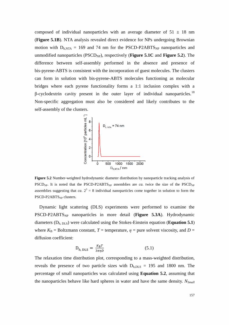
157
composed of individual nanoparticles with an average diameter of 51 ± 18 nm
(Figure 5.1B). NTA analysis revealed direct evidence for NPs undergoing Brownian
motion with Dh,NTA = 169 and 74 nm for the PSCD-P2ABTSNP nanoparticles and
unmodified nanoparticles (PSCDNP), respectively (Figure 5.1C and Figure 5.2). The
difference between self-assembly performed in the absence and presence of
bis-pyrene-ABTS is consistent with the incorporation of guest molecules. The clusters
can form in solution with bis-pyrene-ABTS molecules functioning as molecular
bridges where each pyrene functionality forms a 1:1 inclusion complex with a
β-cyclodextrin cavity present in the outer layer of individual nanoparticles.18
Non-specific aggregation must also be considered and likely contributes to the
self-assembly of the clusters.
Figure 5.2 Number-weighted hydrodynamic diameter distribution by nanoparticle tracking analysis of
PSCDNP. It is noted that the PSCD-P2ABTSNP assemblies are ca. twice the size of the PSCDNP
assemblies suggesting that ca. 23 = 8 individual nanoparticles come together in solution to form the
PSCD-P2ABTSNP clusters.
Dynamic light scattering (DLS) experiments were performed to examine the
PSCD-P2ABTSNP nanoparticles in more detail (Figure 5.3A). Hydrodynamic
diameters (Dh, DLS) were calculated using the Stokes-Einstein equation (Equation 5.1)
where KB = Boltzmann constant, T = temperature, η = pure solvent viscosity, and D =
diffusion coefficient:
Dh, DLS = 𝐾B𝑇
3𝜋𝜂𝐷 (5.1)
The relaxation time distribution plot, corresponding to a mass-weighted distribution,
reveals the presence of two particle sizes with Dh,DLS = 195 and 1800 nm. The
percentage of small nanoparticles was calculated using Equation 5.2, assuming that
the nanoparticles behave like hard spheres in water and have the same density. NSmall

158
refers to the number of small nanoparticles, τSmall is the relaxation time corresponding
to the small nanoparticles (fast relaxation mode), and SSmall is the surface area under
the peak related to the small nanoparticles: 19
𝑁𝑆𝑚𝑎𝑙𝑙
𝑁𝐵𝑖𝑔= (
𝜏𝐵𝑖𝑔
𝜏𝑆𝑚𝑎𝑙𝑙)
3
(𝑆𝑆𝑚𝑎𝑙𝑙
𝑆𝐵𝑖𝑔) (5.2)
The smaller population is complimentary to that obtained by NTA. The larger
population confirms the presence of large agglomerations in the suspension but their
presence is very small in number terms. Hence, the estimated number of the smaller
objects with Dh,DLS = 195 nm is 97.5%.
Figure 5.3 (A) DLS autocorrelation function (g(2)
– 1) measured at 90° and relaxation time distribution
of PSCD-P2ABTSNP. (B) UV-visible spectra for (red) PSCD-P2ABTSNP, (black) PSCDNP and
(pink·-) H2O-P2ABTS. (C) CVs at glassy carbon of as-prepared (red) PSCD-P2ABTSNP and (black)
PSCDNP at 100 mV s-1
. (D) Corresponding plots of peak current vs. the square root of the scan rate for
PSCD-P2ABTSNP.
The feasibility to encapsulate bis-pyrene-ABTS during nanoparticle self-assembly
was established by UV-visible spectroscopy (Figure 5.3B). Three suspensions were
investigated: as-prepared PSCDNP and PSCD-P2ABTSNP, and saturated
bis-pyrene-ABTS (H2O-P2ABTS) in 0.1 mol L-1
phosphate buffer (PB). The
absorption spectrum for PSCDNP shows background absorbance due to the polymer
and no well-defined peaks. In contrast, PSCD-P2ABTSNP and H2O-P2ABTS exhibit a
single well-defined absorption peak at λmax = 344 and 340 nm, respectively,
confirming the presence of the ABTS functionality in its reduced state. The absorption

159
is markedly enhanced for PSCD-P2ABTSNP compared to the saturated H2O-P2ABTS
solution, consistent with a dramatic improvement in solubility for bis-pyrene-ABTS
via the polymeric architecture.
The concentration of the bis-pyrene-ABTS in aqueous PSCD-P2ABTSNP solution
was estimated according to classical calibration plots recorded for dissolved ABTS2-
and ABTS•-
(Figure 5.4). A series of ABTS2-
solutions in the concentration range of 2
to 9 μmol L-1
were prepared in 0.1 mol L-1
phosphate buffer (pH 5.6). The absorbance
spectra of the ABTS2-
solutions were measured at wavelengths in the range of 220 to
700 nm. After each measurement, 15 µL of 50 µg mL-1
bilirubin oxidase (BOx)
solution was added to the solution and left for 5 min to react, followed by a second
measurement of absorbance in the same range (Figure 5.4B). The peak absorbance at
340 and 414 nm, representing ABTS2-
and ABTS•-, respectively, were subsequently
measured and plotted vs. ABTS2-
concentration (Figure 5.4C). Linear fitting results
give molar extinction coefficients of 35840 and 33070 L mol-1
cm-1
for ABTS2-
and
ABTS•-, respectively. Based on the linear calibration curves obtained for both ABTS
2-
and ABTS•- solutions, the concentration of bis-pyrene-ABTS was estimated to be 6.5
μmol L-1
.
Figure 5.4 (A) UV-visible absorption spectra of (i) PSCD-P2ABTSNP and (ii) PSCD-P2ABTSNP with
11 nmol L-1
BOx. (B) UV-visible absorption spectra of (i) 2, (ii) 4, (iii) 5, (iv) 6, (v) 7 and (vi) 9 μmol
L-1
of (solid line) ABTS2-
and (dashed line) ABTS•-
with 11 nmol L-1
BOx. (C) Linear calibration
curves determined from the spectra in (B) according to Beer-Lambert Law. The calibration plot
performed with ABTS•- at λmax = 414 nm was used to eliminate the possible interference of pyrene and
served as a second method to estimate the concentration.
The electrochemical activity of as-prepared PSCD-P2ABTSNP and PSCDNP
nanoparticles in aqueous solutions was investigated at a glassy carbon electrode (GCE)
without additional supporting electrolyte. Figure 5.3C shows cyclic voltammograms
(CVs) recorded at 100 mV s-1
of the redox encapsulated and control nanoparticles.
The CV clearly shows an electrochemically reversible redox couple at E1/2 = 0.46 V

160
corresponding to the one electron oxidation of ABTS2-
to ABTS•- for
PSCD-P2ABTSNP. No redox signal is observed for PSCDNP in the absence of
bis-pyrene-ABTS. The redox functionalities are therefore clearly present and
accessible. The plots in Figure 5.3D and Figure 5.5 show that the peak currents for
the oxidation and reduction processes are proportional to the square root of the scan
rate, as expected for diffusion-controlled behavior. Poor fitting was observed for the
peak current vs. scan rate over a wide scan rate range, discounting the presence of
adsorbed electroactive species. Furthermore, after recording several CV cycles in
PSCD-P2ABTSNP solution, no evidence for adsorbed electroactive NPs was observed
at a GCE in PB (Figure 5.6). Although this data does not reveal evidence for NP
adsorption, the possibility of dynamic adsorption/desorption during potential cycling
cannot be entirely ruled out. Repeated potential cycling of PSCD-P2ABTSNP showed
good stability with little change in the electrochemical redox activity after 10 cycles
(Figure 5.7). The electrochemical stability provides further evidence for the stable
entrapment of bis-pyrene-ABTS as well as the oxidized radical form in the
nanoparticles.
Figure 5.5 Plots of peak current recorded at glass carbon electrode vs. (A) square root of the scan rate
and (B) scan rate for as-prepared PSCD-P2ABTSNP solution for scan rates between 1 mV s-1
and 2 V
s-1
.

161
Figure 5.6 CV recorded at a GCE in 0.1 mol L-1
PB pH 7 at 100 mV s-1
to test for the presence of
adsorbed species after performing a scan rate study in as-prepared aqueous PSCD-P2ABTSNP solution
(ca. 15 potential cycles from 0 V to 0.8 V) then rinsing the electrode with 0.1 mol L-1
PB pH 7.
Figure 5.7 Ten consecutive CVs recorded of as-prepared aqueous PSCD-P2ABTSNP solution at GCE
(pH = 5.6) at 100 mV s-1
.
5.3.2 Oxygen reduction performance
Next the catalytic activity of the PSCD-P2ABTSNP nanoparticles for the 4-electron
4-proton reduction of O2 to water with BOx from Myrothecium verrucaria (MvBOx,
68 kDa) was investigated. This enzyme offers high enzymatic activity, stability at
neutral pH, and a relatively good stability towards chloride ions.20
Figure 5.8 shows
CVs which demonstrate bioelectrocatalytic O2 reduction at GCE with 3.5 μmol L-1
BOx in quiescent oxygen saturated solution ([O2] ~ 1.1 mmol L-1
). A summary of the
catalytic parameters are displayed in Table 5.1. For all cases, the limiting catalytic
currents were obtained from CV scans at 0.1 V vs. SCE. The biocathodes prepared
with the dissolved mediators, bis-pyrene-ABTS and ABTS2-
, exhibited maximum
current densities for O2 reduction of -0.67 ± 0.15 μA cm-2
(Figure 5.8A) and -1.20 ±
0.03 μA cm-2
(Figure 5.8E), respectively. The smaller current observed with
bis-pyrene-ABTS is consistent with its very poor solubility. For the biocathode
without NPs or dissolved mediator, a limiting current of 1.39 ± 0.46 μA cm-2
was
obtained (Figure 5.8D). For this case, effective DET is clearly observed between

162
GCE and BOx in solution. Quasi-steady-state (sigmoidal) voltammograms are
obtained for the PSCD-P2ABTSNP biocathode which exhibits a comparably
remarkable current density of -3.97 ± 0.86 μA cm-2
(Figure 5.8C). For control
experiments utilizing PSCDNP nanoparticles, very low current densities were observed
due to the insulating polymeric structure blocking ET between the enzyme and the
electrode (Figure 5.8B). PSCD-P2ABTSNP solutions prepared at different
concentrations (with Dh,DLS between 190 and 390 nm) demonstrated a linear
dependence of catalytic current on mediator concentration and also revealed a
catalytic improvement with the NPs compared to dissolved ABTS2-
(Figure 5.9 and
5.10)
Figure 5.8 CVs recorded at GCE at 5 mV s-1
(pH = 5.6) with (black--) argon saturation and (red-) O2
saturation with BOx for (A) saturated bis-pyrene-ABTS in PB, (B) as-prepared PSCDNP (pH = 5.9), (C)
as-prepared PSCD-P2ABTSNP, (D) BOx only, and (E) ABTS in PB. [BOx] = 3.5 μmol L-1
and
[mediator] = 6.5 μmol L-1
(˂ 6.5 μmol L-1
for saturated bis-pyrene-ABTS).
Table 5.1 Catalytic parameters from cyclic voltammetry at glassy carbon cathodes with 3.5 μmol L-1
BOx and mediator in solution under oxygen saturated conditions
Electrode
interface
E1/2 mediator
(V vs SCE)
Electron
transfer
Onset
potential
(V vs. SCE)
Maximum Jcat (μA
cm-2
)e
GCE-P2ABTS-BOxa,d
- MET 0.547 ± 0.002 -0.67 ± 0.15
GCE-PSCDNP-BOxc - DET 0.478 ± 0.008 -0.30 ± 0.02
GCE-P2ABTSNP-BOxb,c
0.46 MET 0.532 ± 0.020 -3.97 ± 0.86
GCE-BOxd - DET 0.543 ± 0.003 -1.39 ± 0.46

163
GCE-ABTS-BOxb,d
0.46 MET 0.543 ± 0.005 -1.20 ± 0.03
a [med] ˂ 6.5 μmol L
-1,
b [med] = 6.5 μmol L
-1,
c as-prepared solution,
d 0.1 mol L
-1 phosphate buffer (pH = 5.6),
e current
measured at 0.1 V vs. SCE from CVs.
Figure 5.9 DLS analysis of as-prepared PSCD-P2ABTSNP and diluted PSCD-P2ABTSNP solutions
used to investigate catalytic as a function of mediator concentration. Dilutions with estimated
bis-pyrene-ABTS concentrations were prepared in purified water: 3.25 μmol L-1
(2 times), 2.17 μmol
L-1
(3 times), 1.3 μmol L-1
(5 times) and 0.65 μmol L-1
(10 times). At least 3 DLS measurements were
performed per solution type.
Figure 5.10 Plots of catalytic current versus mediator concentration for as-prepared and diluted
PSCD-P2ABTSNP solutions (black) and ABTS2-
in phosphate buffer (pH = 5.6) (red) vs. mediator
concentration. [BOx] = 0.5 μmol L-1
. Current measured from amperograms recorded at 0.2 V vs. SCE
after 600 seconds with O2 saturation and stirring at 100 rpm.
The enhancement in catalytic current observed for PSCD-P2ABTSNP is consistent
with an efficient intra-electron transfer chain between neighboring ABTS redox units
of clustered particles and the mono- and tri-nuclear Cu sites of enzymes in solution, as
represented in Figure 5.11A. The redox conduction observed for bis-pyrene-ABTS
nanoparticles at GCE is explained by the phenomena of electron hopping widely
reported for redox polymers,21
where electron transfer proceeds by sequential
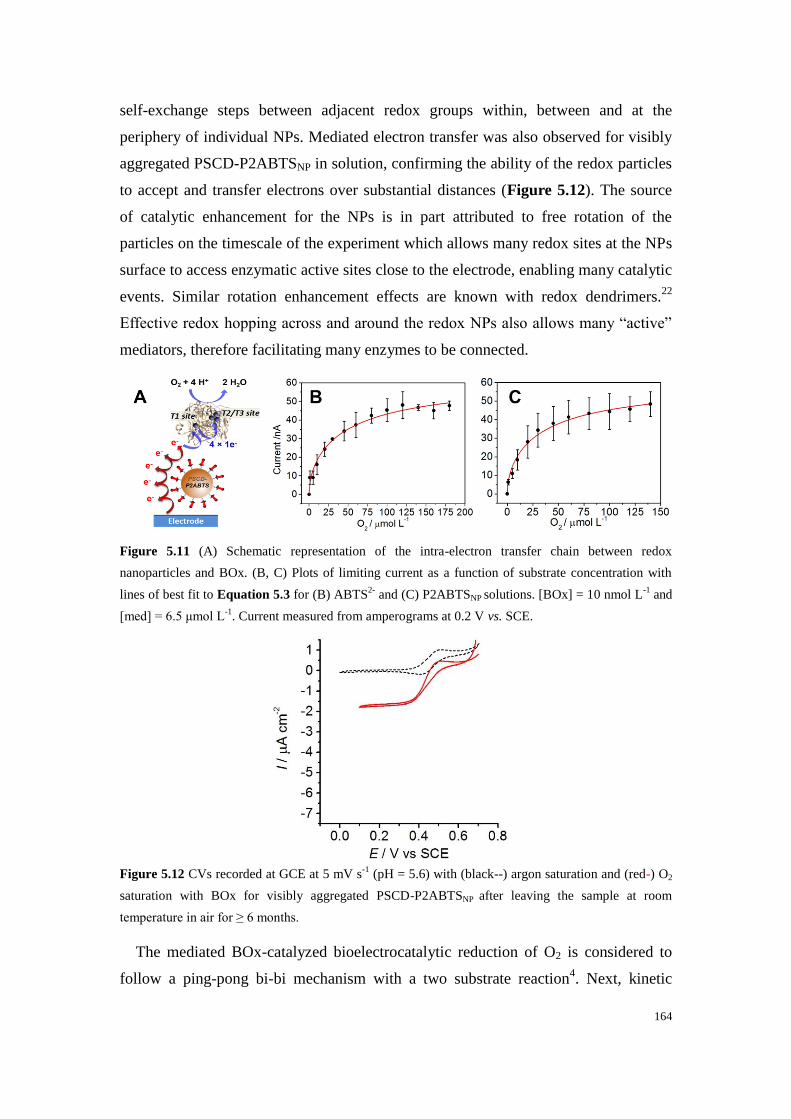
164
self-exchange steps between adjacent redox groups within, between and at the
periphery of individual NPs. Mediated electron transfer was also observed for visibly
aggregated PSCD-P2ABTSNP in solution, confirming the ability of the redox particles
to accept and transfer electrons over substantial distances (Figure 5.12). The source
of catalytic enhancement for the NPs is in part attributed to free rotation of the
particles on the timescale of the experiment which allows many redox sites at the NPs
surface to access enzymatic active sites close to the electrode, enabling many catalytic
events. Similar rotation enhancement effects are known with redox dendrimers.22
Effective redox hopping across and around the redox NPs also allows many “active”
mediators, therefore facilitating many enzymes to be connected.
Figure 5.11 (A) Schematic representation of the intra-electron transfer chain between redox
nanoparticles and BOx. (B, C) Plots of limiting current as a function of substrate concentration with
lines of best fit to Equation 5.3 for (B) ABTS2-
and (C) P2ABTSNP solutions. [BOx] = 10 nmol L-1
and
[med] = 6.5 μmol L-1
. Current measured from amperograms at 0.2 V vs. SCE.
Figure 5.12 CVs recorded at GCE at 5 mV s-1
(pH = 5.6) with (black--) argon saturation and (red-) O2
saturation with BOx for visibly aggregated PSCD-P2ABTSNP after leaving the sample at room
temperature in air for ≥ 6 months.
The mediated BOx-catalyzed bioelectrocatalytic reduction of O2 is considered to
follow a ping-pong bi-bi mechanism with a two substrate reaction4. Next, kinetic
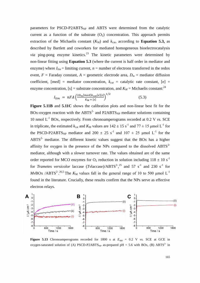
165
parameters for PSCD-P2ABTSNP and ABTS were determined from the catalytic
current as a function of the substrate (O2) concentration. This approach permits
extraction of the Michaelis constant (KM) and kcat, according to Equation 5.3, as
described by Bartlett and coworkers for mediated homogeneous bioelectrocatalysis
via ping-pong enzyme kinetics.23
The kinetic parameters were determined by
non-linear fitting using Equation 5.3 (where the current is half order in mediator and
enzyme) where Ilim = limiting current, n = number of electrons transferred in the redox
event, F = Faraday constant, A = geometric electrode area, Dm = mediator diffusion
coefficient, [med] = mediator concentration, kcat = catalytic rate constant, [e] =
enzyme concentration, [s] = substrate concentration, and KM = Michaelis constant:24
𝐼𝑙𝑖𝑚 = 𝑛𝐹𝐴 (2𝐷𝑚[𝑚𝑒𝑑]𝑘cat[𝑒][𝑠]
𝐾M + [𝑠])
1/2
(5.3)
Figure 5.11B and 5.11C shows the calibration plots and non-linear best fit for the
BOx-oxygen reaction with the ABTS2-
and P2ABTSNP mediator solutions containing
10 nmol L-1
BOx, respectively. From chronoamperograms recorded at 0.2 V vs. SCE
in triplicate, the estimated kcat and KM values are 142 ± 15 s-1
and 77 ± 15 μmol L-1
for
the PSCD-P2ABTSNP mediator and 200 ± 25 s-1
and 107 ± 25 μmol L-1
for the
ABTS2-
mediator. The different kinetic values suggest that the BOx has a higher
affinity for oxygen in the presence of the NPs compared to the dissolved ABTS2-
mediator, although with a slower turnover rate. The values obtained are of the same
order reported for MCO enzymes for O2 reduction in solution including 118 ± 10 s-1
for Trametes versicolor laccase (Tvlaccase)/ABTS2-
,25
and 57 s-1
and 230 s-1
for
MvBOx /ABTS2-
.26,5
The KM values fall in the general range of 10 to 500 μmol L-1
found in the literature. Crucially, these results confirm that the NPs serve as effective
electron relays.
Figure 5.13 Chronoamperograms recorded for 1800 s at Eapp = 0.2 V vs. SCE at GCE in
oxygen-saturated solution of (A) PSCD-P2ABTSNP as-prepared pH = 5.6 with BOx, (B) ABTS2-
in
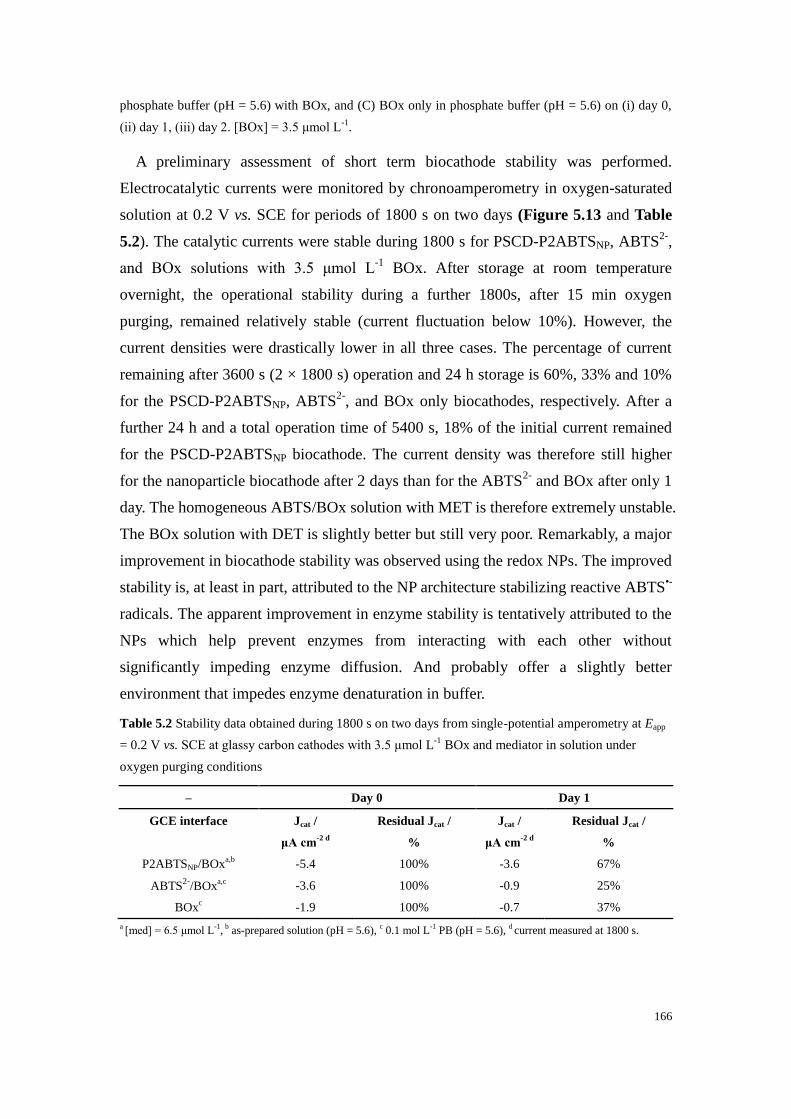
166
phosphate buffer (pH = 5.6) with BOx, and (C) BOx only in phosphate buffer (pH = 5.6) on (i) day 0,
(ii) day 1, (iii) day 2. [BOx] = 3.5 μmol L-1
.
A preliminary assessment of short term biocathode stability was performed.
Electrocatalytic currents were monitored by chronoamperometry in oxygen-saturated
solution at 0.2 V vs. SCE for periods of 1800 s on two days (Figure 5.13 and Table
5.2). The catalytic currents were stable during 1800 s for PSCD-P2ABTSNP, ABTS2-
,
and BOx solutions with 3.5 μmol L-1
BOx. After storage at room temperature
overnight, the operational stability during a further 1800s, after 15 min oxygen
purging, remained relatively stable (current fluctuation below 10%). However, the
current densities were drastically lower in all three cases. The percentage of current
remaining after 3600 s (2 × 1800 s) operation and 24 h storage is 60%, 33% and 10%
for the PSCD-P2ABTSNP, ABTS2-
, and BOx only biocathodes, respectively. After a
further 24 h and a total operation time of 5400 s, 18% of the initial current remained
for the PSCD-P2ABTSNP biocathode. The current density was therefore still higher
for the nanoparticle biocathode after 2 days than for the ABTS2-
and BOx after only 1
day. The homogeneous ABTS/BOx solution with MET is therefore extremely unstable.
The BOx solution with DET is slightly better but still very poor. Remarkably, a major
improvement in biocathode stability was observed using the redox NPs. The improved
stability is, at least in part, attributed to the NP architecture stabilizing reactive ABTS•-
radicals. The apparent improvement in enzyme stability is tentatively attributed to the
NPs which help prevent enzymes from interacting with each other without
significantly impeding enzyme diffusion. And probably offer a slightly better
environment that impedes enzyme denaturation in buffer.
Table 5.2 Stability data obtained during 1800 s on two days from single-potential amperometry at Eapp
= 0.2 V vs. SCE at glassy carbon cathodes with 3.5 μmol L-1
BOx and mediator in solution under
oxygen purging conditions
– Day 0 Day 1
GCE interface Jcat /
μA cm-2 d
Residual Jcat /
%
Jcat /
μA cm-2 d
Residual Jcat /
%
P2ABTSNP/BOxa,b
-5.4 100% -3.6 67%
ABTS2-
/BOxa,c
-3.6 100% -0.9 25%
BOxc -1.9 100% -0.7 37%
a [med] = 6.5 μmol L
-1, b as-prepared solution (pH = 5.6),
c 0.1 mol L
-1 PB (pH = 5.6),
d current measured at 1800 s.

167
5.4 Conclusion
In conclusion, this work demonstrates the ability of polymeric glyconanoparticles
containing redox-active bis-pyrene-ABTS molecules to function as electron shuttles
in solution for the electrical wiring of BOx. Thanks to an intimate MET exchange
between nanoparticles containing a high density of electron acceptors, enhanced
catalytic currents have been observed compared to homogeneous mediators. In
addition to enhanced catalytic performance and low overpotentials, the biocathode
with redox nanoparticles showed dramatically improved stability after 60 min
operation and 24 h storage, suggesting that the polymer architecture stabilizes both
the enzyme and mediator. Furthermore, the large size of the nanoparticles should
permit their containment in permselective membranes. In future work, the
nanoparticle system will be exploited to solubilize new hydrophobic mediators at high
concentrations for bioelectrocatalysis towards a refuelable all-in-solution biofuel cell
for powering electronics devices. Biofuel cell designs are envisaged in which
enzymes and nanoparticles are periodically introduced to prolong biofuel cell lifetime.
5.5 Experimental Section
5.5.1 Materials and reagents
Mono-sodium phosphate monohydrate (NaH2PO4, ≥ 98%), di-sodium hydrogen
phosphate heptahydrate (Na2HPO4, ≥ 98%),
2,2'-azino-bis(3-ethylbenzothiazoline-6-sulphonic acid) (ABTS) diammonium salt ( ˃
98%), propargylamine, sodium hydroxide (NaOH), potassium tert-butoxide,
pyrenemethylammonium hydrochloride,
benzotriazol-1-yloxytris(dimethylamino)phosphoniumhexafluorophosphate,
tetrahydrofuran (THF) and sodium azide (NaN3) were purchased from Sigma Aldrich
and used as received. The ω-hydroxy-polystyrene (Mn = 3800 g mol–1
) was purchased
from Polymer Source. β-Cyclodextrin and Cu/CuO nanopowder were purchased from
Alfa Aesar, tosyl chloride (TsCl) was obtained from Fluka, pyridine was purchased at
SDS, N-methyl-2-pyrrolidone (NMP, ˃ 99%) was purchased from Acros Organics,
and methanol (MeOH) and dichloromethane (CH2Cl2) were purchased from Biosolve.
Bilirubin oxidase (BOx, EC 1.3.3.5, with determined activity of 8.362 U mg-1
solid /
9.098 U mL-1
) from Myrothecium sp. was purchased from Amano (Japan), stored at
-20 °C, and used as received. Purified water was obtained by water purification to a

168
resistivity of 18.2 MΩ cm using a Millipore Ultrapure system. High purity oxygen
and argon were obtained from Messer.
5.5.2 Synthesis protocols
5.5.2.1 Synthesis of polystyrene-b-β-cyclodextrin (PSCD)
The amphiphilic β-cyclodextrin-modified polystyrene polymer (PSCD) (Mn = 4900
g mol–1
) was obtained by click chemistry of functionalized polystyrene and
β-cyclodextrin blocks using a Cu nanopowder catalyst according to our previous work
with a yield of 8 g (90%) according to the reported procedure (see Scheme 5.1).17
Scheme 5.1 Synthetic pathway for preparation of polystyrene-b-β-cyclodextrin (PSCD).
5.5.2.2 Synthesis of bis-pyrene-2,2'-azino-bis(3-ethylbenzothiazoline-6-sulfonic acid)
(bis-pyrene-ABTS; P2ABTS)
The bis-pyrene-ABTS compound was synthesized by reaction of
1-pyrenemethylamine, 2,2'-azino-bis(3-ethylbenzothiazoline-6-sulphonic acid)
(ABTS) potassium salt and
benzotriazol-1-yloxytris(dimethylamino)phosphoniumhexafluorophosphate, with a
yield of 65% according to the reported procedure.27
5.5.2.3 Self-assembly of PSCDNP and PSCD-P2ABTSNP via nanoprecipitation
Polymer solutions were prepared by dissolving either 10.3 mg of PSCD, or 10.3 mg
of PSCD together with 5 mg of bis-pyrene-ABTS (i.e. 1:3 moles polymer to
bis-pyrene-ABTS), in 4 mL of NMP. The mixtures were subsequently mechanically
agitated at 500 rpm overnight then sonicated at room temperature for 10-15 min. For

169
nanoprecipitation, 1 g of the polymer solution was slowly added dropwise to 40 g of
purified water under stirring at 500 rpm. The resulting suspension was subsequently
stirred at room temperature at 500 rpm for 1.5 h. The suspension was then dialyzed
against purified water (cut-off = 3500 Da; one night; 3 × 2 L purified water
replacements). The nanoparticle suspensions were stored at room temperature.
5.5.3 Characterization protocols
5.5.3.1 Nanoparticle tracking analysis (NTA)
NTA was performed to obtain number-weighted hydrodynamic distributions using a
Nanosight LM10HS optical microscope equipped with a blue-purple laser (λex = 405
nm), a camera and a chamber mounted on a modified microscope stage (Nanosight,
Amesbury, UK). The original aqueous suspensions of nanoparticles were diluted with
purified water and introduced into the chamber by a syringe. Video clips of the
nanoparticles subjected to their natural Brownian motion were captured over 60 s at
25.0 °C and analyzed using the analytical software version 2.1, giving access to
number-weighted size distributions.
5.5.3.2 Transmission electron microscopy (TEM)
5 L of nanoparticle suspension was dropped onto a glow discharged carbon-coated
copper grid. 5 L of 2 w/v % aqueous uranyl acetate stain solution was added and the
sample dried in a desiccator overnight. Imaging was performed at 200 kV using a
Philips CM200 microscope with a TEM-CAM 216 (TVIPS) camera.
5.5.3.3 Dynamic light scattering (DLS)
Dynamic light scattering measurements were performed using an
ALV/CGS-8FS/N069 goniometer with an ALV/LSE-5004 multiple τ digital corrector
with a 125 ns initial sampling time and a 35 mW red HeNe linearly polarized laser
operating at λ = 632.8 nm. Nanoparticle suspensions were loaded into 10 mm
diameter quartz cells thermostatted at 25 ± 0.1 °C. Data were collected using the
digital ALV correlator control software at an observation angle relative to the
transmitted beam of 90° (scattering vector modulus 1.87 × 10⁻²
nm-1
) for a counting
time of typically 180 s. Relaxation time distributions were determined using Contin
analysis of the autocorrelation functions.

170
5.5.3.4 UV-visible spectroscopy
UV-visible absorption spectra were recorded in quartz cuvettes using a Perkin
Elmer UV-Lambda 650 spectrophotometer at room temperature with a 1 cm optical
path length. The enzymatic activity of bilirubin oxidase was determined from the
absorbance of the oxidized ABTS radical (ABTS•-) formed by reaction in the
presence of oxygen and BOx in 0.1 mol L-1
phosphate buffer (pH = 5.6) (Equation
5.4 and Figure 5.14). The evolution of the absorbance of ABTS•- was measured at a
fixed wavelength of 414 nm for 5 min. The background absorbance was obtained
from a phosphate buffer solution containing only ABTS2-
and no enzyme. Specifically,
1.088 mg of BOx was dissolved in 1 mL of 0.1 mol L-1
phosphate buffer (pH = 5.6).
The solution was then diluted by a factor of 10 to 0.1088 mg mL-1
. The enzymatic
reaction experiment was initiated immediately after addition and mixing of 4.6 µL
enzyme solution to 50 µmol L-1
ABTS2-
solution at a final volume of 1 mL. The
enzymatic activity was calculated using Equation 5.5 where 𝑑𝐴/𝑑𝑡 = absorbance
change per time unit, L = optical path length, ε = millimolar extinction coefficient of
ABTS•- (ε = 33.07 L mmol-1
cm-1
), Vtotal = final volume of the reaction mixture in the
cuvette, df = dilution factor of enzyme solution, and Venzyme = volume of enzyme
solution added to the cuvette.
4 ABTS2-
+ O2 + 4H+
4 ABTS•- + 2H2O (5.4)
Enzyme activity (U mg-1
solid) =𝑑𝐴
dt×
L
ε× Vtotal × df
𝑉enzyme (5.5)
Figure 5.14 (A) Spectrophotometric enzyme assay recorded at λ = 414 nm for 300 s in 50 µmol L-1
ABTS2-
in phosphate buffer (pH = 5.6) with (i) 7.3 nmol L-1
BOx and (ii) without BOx. (B) Fitting of
the linear region of the curve (i) shown in (A) for a minimum of 2 min.

171
5.5.3.5 Electrochemistry
Electrochemical measurements were performed at room temperature using an Eco
Chemie Autolab PGSTAT 100 potentiostat running Nova 2.1 software. A conventional
three-electrode cell setup was used for all electrochemical experiments comprising a
glassy carbon working electrode (GCE, 3 mm diameter), a saturated calomel
reference electrode (SCE) and a Pt wire counter electrode. Diffusion coefficients were
estimated according to the Randles-Sevcik equation (Equation 5.6) at room
temperature (25 °C) where Ip = peak current, n = number of electrons transferred in
the redox event, A = geometric electrode area, D = diffusion coefficient, C =
concentration of electroactive species, and ν = scan rate: 28
𝐼𝑝 = (2.69 × 10⁵) 𝑛3/2𝐴𝐷1/2𝐶𝜈1/2 (5.6)
The enzyme-substrate kinetic parameters, kcat and KM, were determined from a plot
of the catalytic current at varying oxygen concentrations (1 to 300 μmol L-1
). For
these experiments, the steady state current response was determined from
single-potential amperometry performed at 0.2 V vs. SCE in 0.1 mol L-1
potassium
phosphate buffer (pH = 5.6) containing 10 nmol L-1
BOx. Experiments were
performed at room temperature with stirring at 150 rpm to avoid diffusion limitation.
The oxygen concentration was monitored using an Ocean Optics NeoFox-GT oxygen
sensor probe and NeoFox viewer software.

172
References
1. Moser, C. C., Keske, J. M., Warncke, K., Farid, R. S. & Dutton, P. L. Nature of biological
electron transfer. Nature 355, 796–802 (1992).
2. Saboe, P. O., Conte, E., Farell, M., Bazan, G. C. & Kumar, M. Biomimetic and bioinspired
approaches for wiring enzymes to electrode interfaces. Energy Environ. Sci. 10, 14–42 (2017).
3. Cosnier, S., J. Gross, A., Le Goff, A. & Holzinger, M. Recent advances on enzymatic
glucose/oxygen and hydrogen/oxygen biofuel cells: Achievements and limitations. Journal of
Power Sources 325, 252–263 (2016).
4. Stines-Chaumeil, C., Roussarie, E. & Mano, N. The nature of the rate-limiting step of blue
multicopper oxidases: Homogeneous studies versus heterogeneous. Biochimie Open 4, 36–40
(2017).
5. Tsujimura, S. et al. Bioelectrocatalytic reduction of dioxygen to water at neutral pH using
bilirubin oxidase as an enzyme and 2,2′-azinobis (3-ethylbenzothiazolin-6-sulfonate) as an
electron transfer mediator. Journal of Electroanalytical Chemistry 496, 69–75 (2001).
6. Kano, K. & Ikeda, T. Fundamentals and Practices of Mediated Bioelectrocatalysis. Analytical
Sciences 16, 1013–1021 (2000).
7. Ruff, A. Redox polymers in bioelectrochemistry: Common playgrounds and novel concepts.
Current Opinion in Electrochemistry just accepted, (2017).
8. Xiao, Y., Patolsky, F., Katz, E., Hainfeld, J. F. & Willner, I. ‘Plugging into Enzymes’:
Nanowiring of Redox Enzymes by a Gold Nanoparticle. Science 299, 1877–1881 (2003).
9. Zayats, M., Katz, E., Baron, R. & Willner, I. Reconstitution of Apo-Glucose Dehydrogenase on
Pyrroloquinoline Quinone-Functionalized Au Nanoparticles Yields an Electrically Contacted
Biocatalyst. J. Am. Chem. Soc. 127, 12400–12406 (2005).
10. Lalaoui, N. et al. Direct Electron Transfer between a Site-Specific Pyrene-Modified Laccase and
Carbon Nanotube/Gold Nanoparticle Supramolecular Assemblies for Bioelectrocatalytic
Dioxygen Reduction. ACS Catal. 6, 1894–1900 (2016).
11. Holland, J. T., Lau, C., Brozik, S., Atanassov, P. & Banta, S. Engineering of Glucose Oxidase for
Direct Electron Transfer via Site-Specific Gold Nanoparticle Conjugation. J. Am. Chem. Soc. 133,
19262–19265 (2011).
12. Gutiérrez-Sánchez, C., Pita, M., Vaz-Domínguez, C., Shleev, S. & De Lacey, A. L. Gold
Nanoparticles as Electronic Bridges for Laccase-Based Biocathodes. J. Am. Chem. Soc. 134,
17212–17220 (2012).
13. Trifonov, A., Tel-Vered, R., Fadeev, M. & Willner, I. Electrically Contacted
Bienzyme-Functionalized Mesoporous Carbon Nanoparticle Electrodes: Applications for the
Development of Dual Amperometric Biosensors and Multifuel-Driven Biofuel Cells. Adv.
Energy Mater. 5, 1401853 (2015).
14. Aquino Neto, S., Forti, J. C., Zucolotto, V., Ciancaglini, P. & De Andrade, A. R. The kinetic
behavior of dehydrogenase enzymes in solution and immobilized onto nanostructured carbon
platforms. Process Biochemistry 46, 2347–2352 (2011).
15. A. Sheldon, R. & Pelt, S. van. Enzyme immobilisation in biocatalysis: why, what and how.

173
Chemical Society Reviews 42, 6223–6235 (2013).
16. Li, J.-J., Chen, Y., Yu, J., Cheng, N. & Liu, Y. A Supramolecular Artificial Light-Harvesting
System with an Ultrahigh Antenna Effect. Adv. Mater. 29, 1701905 (2017).
17. Gross, A. J. et al. Redox-Active Carbohydrate-Coated Nanoparticles: Self-Assembly of a
Cyclodextrin–Polystyrene Glycopolymer with Tetrazine–Naphthalimide. Langmuir 32, 11939–
11945 (2016).
18. Liu, P. et al. Competitive Host–Guest Interaction between β-Cyclodextrin Polymer and
Pyrene-Labeled Probes for Fluorescence Analyses. Anal. Chem. 87, 2665–2671 (2015).
19. Korchia, L. et al. Photodimerization as an alternative to photocrosslinking of nanoparticles:
proof of concept with amphiphilic linear polyoxazoline bearing coumarin unit. Polym. Chem. 6,
6029–6039 (2015).
20. Mano, N. & Edembe, L. Bilirubin oxidases in bioelectrochemistry: Features and recent findings.
Biosensors and Bioelectronics 50, 478–485 (2013).
21. Heller, A. Miniature biofuel cells. Phys. Chem. Chem. Phys. 6, 209–216 (2004).
22. Goldsmith, J. I., Takada, K. & Abruña, H. D. Probing Diffusional Transport in Redox-Active
Dendrimers. J. Phys. Chem. B 106, 8504–8513 (2002).
23. Flexer, V., Ielmini, M. V., Calvo, E. J. & Bartlett, P. N. Extracting kinetic parameters for
homogeneous [Os(bpy)2ClPyCOOH]+ mediated enzyme reactions from cyclic voltammetry and
simulations. Bioelectrochemistry 74, 201–209 (2008).
24. Bartlett, P. N. & Pratt, K. F. E. A study of the kinetics of the reaction between ferrocene
monocarboxylic acid and glucose oxidase using the rotating-disc electrode. Journal of
Electroanalytical Chemistry 397, 53–60 (1995).
25. Farneth, W. E., Diner, B. A., Gierke, T. D. & D’Amore, M. B. Current densities from
electrocatalytic oxygen reduction in laccase/ABTS solutions. Journal of Electroanalytical
Chemistry 581, 190–196 (2005).
26. Pankratov, D. et al. The influence of nanoparticles on enzymatic bioelectrocatalysis. RSC
Advances 4, 38164 (2014).
27. Bourourou, M. et al. Freestanding redox buckypaper electrodes from multi-wall carbon
nanotubes for bioelectrocatalytic oxygen reduction via mediated electron transfer. Chemical
Science 5, 2885–2888 (2014).
28. Kissinger, P. T. & Heineman, W. R. Cyclic voltammetry. J. Chem. Educ. 60, 702 (1983).

174

175
Chapter 6:
Conclusions and
perspectives

176
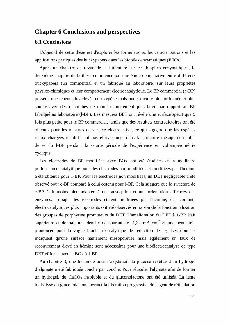
177
Chapter 6 Conclusions and perspectives
6.1 Conclusions
L'objectif de cette thèse est d'explorer les formulations, les caractérisations et les
applications pratiques des buckypapers dans les biopiles enzymatiques (EFCs).
Après un chapitre de revue de la littérature sur ces biopiles enzymatiques, le
deuxième chapitre de la thèse commence par une étude comparative entre différents
buckypapers (un commercial et un fabriqué au laboratoire) sur leurs propriétés
physico-chimiques et leur comportement électrocatalytique. Le BP commercial (c-BP)
possède une teneur plus élevée en oxygène mais une structure plus ordonnée et plus
souple avec des nanotubes de diamètre nettement plus large par rapport au BP
fabriqué au laboratoire (l-BP). Les mesures BET ont révélé une surface spécifique 9
fois plus petite pour le BP commercial, tandis que des résultats contradictoires ont été
obtenus pour les mesures de surface électroactive, ce qui suggère que les espèces
redox chargées ne diffusent pas efficacement dans la structure mésoporeuse plus
dense du l-BP pendant la courte période de l'expérience en voltampérométrie
cyclique.
Les électrodes de BP modifiées avec BOx ont été étudiées et la meilleure
performance catalytique pour des électrodes non modifiées et modifiées par l'hémine
a été obtenue pour 1-BP. Pour les électrodes non modifiées, un DET négligeable a été
observé pour c-BP comparé à celui obtenu pour l-BP. Cela suggère que la structure de
c-BP était moins bien adaptée à une adsorption et une orientation efficaces des
enzymes. Lorsque les électrodes étaient modifiées par l'hémine, des courants
électrocatalytiques plus importants ont été observés en raison de la fonctionnalisation
des groupes de porphyrine promoteurs du DET. L'amélioration du DET à 1-BP était
supérieure et donnait une densité de courant de -1,32 mA cm-2
et une pente très
prononcée pour la vague bioélectrocatalytique de réduction de O2. Les données
indiquent qu'une surface hautement mésoporeuse mais également un taux de
recouvrement élevé en hémine sont nécessaires pour une bioélectrocatalyse de type
DET efficace avec la BOx à 1-BP.
Au chapitre 3, une bioanode pour l’oxydation du glucose revêtue d’un hydrogel
d’alginate a été fabriquée couche par couche. Pour réticuler l'alginate afin de former
un hydrogel, du CaCO3 insoluble et du gluconolactone ont été utilisés. La lente
hydrolyse du gluconolactone permet la libération progressive de l'agent de réticulation,

178
l'ion calcium, qui conduit ensuite à un film homogène. Des électrodes autosupportées
(buckypaper) préparées à partir de deux types de CNTs différents ont été construites et
testées. Un courant catalytique plus élevé a été observé pour les CNTs avec une pureté
de carbone plus élevée. La présence d'une couche d'hydrogel diminue le courant
catalytique en raison d'un transfert de masse du substrat plus lent à travers cette
couche, comme le révèlent les études de voltampérométrie cyclique et de
choronoampérométrie. Il est important de noter que la stabilité en stockage a été
améliorée par rapport à une électrode non revêtue. Le revêtement d'hydrogel a été
optimisé en modifiant le volume d'hydrogel et en ajoutant des CNTs à la matrice
d'hydrogel. L'électrode la plus performante a été identifiée comme étant l'électrode
revêtue d'hydrogel préparée à partir du mélange CNTs / alginate, retenant 67% de son
courant électrocatalytique après 5 jours de stockage.
Au chapitre 4, une EFC lactate/O2 extensible et portable qui récupère l'énergie de la
sueur a été créé grâce à la combinaison d'un substrat collecteur de courant sérigraphié
et de PA souples à base de polynorbornène modifié par des enzymes. Au cours
d'expériences in vitro, l'EFC assemblée présentait une valeur d’OCV élevée (de
l’ordre de 0,74 V) et une densité de puissance maximale de 520 µW cm-2
.
L'extensibilité du dispositif a été réalisée grâce au couplage d'une architecture en “îlot”
et d'encres résistantes aux contraintes mécaniques. Le dispositif a pu conserver ses
performances après plusieurs cycles d'étirement. La biopile peut également
fonctionner comme un supercondensateur autonome, pouvant délivrer une puissance
maximale de 6,5 mW cm-2
à une densité de courant impulsionnelle de 20 mA cm-2
.
Après couplage avec un élévateur de tension, le prototype de cette EFC basé sur des
électrodes en BP était en mesure d’alimenter une LED commerciale en mode pulsé et
en mode continu en convertissant l’énergie chimique du lactate présent dans la sueur
(lui-même généré au cours d’un exercice physique).
Le chapitre 5 a mis en évidence l'auto-assemblage et la caractérisation de
nanoparticules enrobées de cyclodextrine contenant des molécules ABTS-bis-pyrène
possédant une activité redox, ainsi que leur capacité à fonctionner en tant que navettes
électroniques en solution pour assurer le transfert électronique médié entre le matériau
d’électrode et la BOx pour la réduction de O2. Les glyconanoparticules encapsulées
ont été préparées par auto-assemblage de polymère de polystyrène modifié par la
β-cyclodextrine (PSCD) en présence de bis-pyrène-ABTS via la nanoprécipitation.
Des nanoparticules encapsulées dans du bis-pyrène-ABTS ont été étudiées par voie
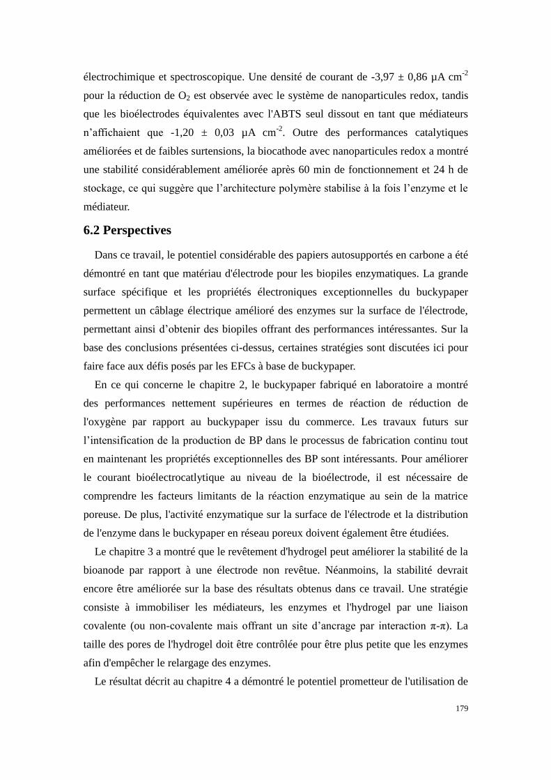
179
électrochimique et spectroscopique. Une densité de courant de -3,97 ± 0,86 µA cm-2
pour la réduction de O2 est observée avec le système de nanoparticules redox, tandis
que les bioélectrodes équivalentes avec l'ABTS seul dissout en tant que médiateurs
n’affichaient que -1,20 ± 0,03 µA cm-2
. Outre des performances catalytiques
améliorées et de faibles surtensions, la biocathode avec nanoparticules redox a montré
une stabilité considérablement améliorée après 60 min de fonctionnement et 24 h de
stockage, ce qui suggère que l’architecture polymère stabilise à la fois l’enzyme et le
médiateur.
6.2 Perspectives
Dans ce travail, le potentiel considérable des papiers autosupportés en carbone a été
démontré en tant que matériau d'électrode pour les biopiles enzymatiques. La grande
surface spécifique et les propriétés électroniques exceptionnelles du buckypaper
permettent un câblage électrique amélioré des enzymes sur la surface de l'électrode,
permettant ainsi d’obtenir des biopiles offrant des performances intéressantes. Sur la
base des conclusions présentées ci-dessus, certaines stratégies sont discutées ici pour
faire face aux défis posés par les EFCs à base de buckypaper.
En ce qui concerne le chapitre 2, le buckypaper fabriqué en laboratoire a montré
des performances nettement supérieures en termes de réaction de réduction de
l'oxygène par rapport au buckypaper issu du commerce. Les travaux futurs sur
l’intensification de la production de BP dans le processus de fabrication continu tout
en maintenant les propriétés exceptionnelles des BP sont intéressants. Pour améliorer
le courant bioélectrocatlytique au niveau de la bioélectrode, il est nécessaire de
comprendre les facteurs limitants de la réaction enzymatique au sein de la matrice
poreuse. De plus, l'activité enzymatique sur la surface de l'électrode et la distribution
de l'enzyme dans le buckypaper en réseau poreux doivent également être étudiées.
Le chapitre 3 a montré que le revêtement d'hydrogel peut améliorer la stabilité de la
bioanode par rapport à une électrode non revêtue. Néanmoins, la stabilité devrait
encore être améliorée sur la base des résultats obtenus dans ce travail. Une stratégie
consiste à immobiliser les médiateurs, les enzymes et l'hydrogel par une liaison
covalente (ou non-covalente mais offrant un site d’ancrage par interaction π-π). La
taille des pores de l'hydrogel doit être contrôlée pour être plus petite que les enzymes
afin d'empêcher le relargage des enzymes.
Le résultat décrit au chapitre 4 a démontré le potentiel prometteur de l'utilisation de

180
BP comme matériau d'électrode à haute performance pour les EFCs cutanées avec un
substrat de support extensible. De tels dispositifs portés à même la peau et étirables
devraient contribuer au développement de systèmes de récupération d'énergie cutanée
et de produits électroniques portables. Ce dispositif des EFCs repose toujours sur des
exercices pour la production de sueur, ce qui limite encore ses utilisations à des fins
sportives uniquement. Différentes stratégies, telles que l'utilisation de produits
chimiques induisant la transpiration1 ou le remplacement de la cathode par une
électrode respirante, permettent de relever des défis, tels que la disponibilité de
biocarburants ou d'oxygène. Les futures études devraient viser à améliorer la
biocompatibilité, les performances catalytiques de chaque bioélectrode et une
intégration électronique plus poussée ainsi que des essais étendus sur d’autres zones
du corps.
Le chapitre 5 a présenté une autre configuration de biocathode avec des
glyconanoparticules et des enzymes redox-actives en solution. Le projet a été
développé plus avant par mon collègue, qui a préparé les glyconanoparticules
contenant de la phénanthrénéquinone piégée en tant que médiateur de la glucose
déshydrogénase dépendante du FAD. Une nouvelle EFC solubilisée a été construite en
combinant les demi-cellules anodiques et cathodiques.2 L'EFC peut être perfectionnée
pour permettre un échange aisé des solutions avec des médiateurs et/ou d’enzymes
actives, ce qui devrait conduire à prolonger la durée de vie du dispositif complet.

181
Chapter 6 Conclusions and perspectives
6.1 Conclusions
The objective of this thesis is to explore the formulations, characterizations and
practical applications of buckypapers in enzymatic biofuel cells.
After a chapter of literature review on enzymatic biofuel cells, the second chapter
of the thesis starts with a comparison study between commercial and lab-made
buckypapers on their physico-chemical properties and catalytic behavior. Commercial
BP possesses higher oxygen content but more ordered and looser structure with
significantly wider diameter nanotubes compared to lab-made BP (l-BP). BET
measurements revealed a 9-times smaller surface area for commercial BP while
contradictory results were obtained for electroactive surface area measurements,
which suggest that the charged redox species did not effectively diffuse into the
denser mesoporous structure of l-BP during the time scale of the experiment.
BP electrodes modified with BOx were studied and the best catalytic performance
at unmodified and hemin-modified electrodes was obtained at l-BP. At unmodified BP,
negligible DET was observed at commercial BP compared to the lab-made
counterpart. This suggests the structure of c-BP was less well suited to effective
enzyme adsorption and orientation. At hemin-modified CNT electrodes, enhanced
currents were observed due to the functionalization of DET promoting porphyrin
groups. The DET enhancement at l-BP was superior and gave a current density of
-1.32 mA cm-2
and a very pronounced slope for the bioelectrocatalytic wave. The data
indicates that highly mesoporous surface but also a high coverage of hemin are
required for effective DET-type bioelectrocatalysis with BOx at l-BP.
In chapter 3, alginate hydrogel-coated glucose oxidizing bioanode was fabricated in
a layer-by-layer configuration. To cross-link alginate to form hydrogel, insoluble
CaCO3 and gluconolactone were used. The slow hydrolysis of gluconolactone enables
the gradual release of cross-linker, calcium ion, which then leads to homogeneous
film. Buckypaper electrodes prepared from two different types of CNTs were
constructed and tested. Higher catalytic current was observed for CNTs with higher
carbon purity. The presence of hydrogel layer decreases the catalytic current due to
slower mass transfer efficiency as revealed by cyclic voltammetry and
choronoamperometry studies. Importantly, both storage and operational stability
improved compared to uncoated electrode. Hydrogel coating was optimized by
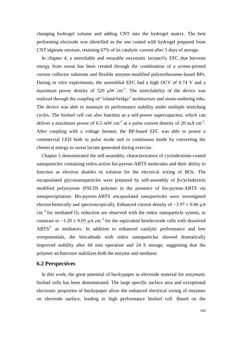
182
changing hydrogel volume and adding CNT into the hydrogel matrix. The best
performing electrode was identified as the one coated with hydrogel prepared from
CNT/alginate mixture, retaining 67% of its catalytic current after 5 days of storage.
In chapter 4, a stretchable and wearable enzymatic lactate/O2 EFC that harvests
energy from sweat has been created through the combination of a screen-printed
current collector substrate and flexible enzyme-modified polynorbornene-based BPs.
During in vitro experiments, the assembled EFC had a high OCV of 0.74 V and a
maximum power density of 520 µW cm-2
. The stretchability of the device was
realized through the coupling of “island-bridge” architecture and strain-enduring inks.
The device was able to maintain its performance stability under multiple stretching
cycles. The biofuel cell can also function as a self-power supercapacitor, which can
deliver a maximum power of 6.5 mW cm-2
at a pulse current density of 20 mA cm-2
.
After coupling with a voltage booster, the BP-based EFC was able to power a
commercial LED both in pulse mode and in continuous mode by converting the
chemical energy in sweat lactate generated during exercise.
Chapter 5 demonstrated the self-assembly, characterization of cyclodextrine-coated
nanoparticles containing redox-active bis-pyrene-ABTS molecules and their ability to
function as electron shuttles in solution for the electrical wiring of BOx. The
encapsulated glyconanoparticles were prepared by self-assembly of β-cyclodextrin
modified polystyrene (PSCD) polymer in the presence of bis-pyrene-ABTS via
nanoprecipitation. Bis-pyrene-ABTS encapsulated nanoparticles were investigated
electrochemically and spectroscopically. Enhanced current density of −3.97 ± 0.86 μA
cm−2
for mediated O2 reduction are observed with the redox nanoparticle system, in
constrast to −1.20 ± 0.03 μA cm−2
for the equivalent bioelectrode cells with dissolved
ABTS2-
as mediators. In addition to enhanced catalytic performance and low
overpotentials, the biocathode with redox nanoparticles showed dramatically
improved stability after 60 min operation and 24 h storage, suggesting that the
polymer architecture stabilizes both the enzyme and mediator.
6.2 Perspectives
In this work, the great potential of buckypaper as electrode material for enzymatic
biofuel cells has been demonstrated. The large specific surface area and exceptional
electronic properties of buckypaper allow the enhanced electrical wiring of enzymes
on electrode surface, leading to high performance biofuel cell. Based on the
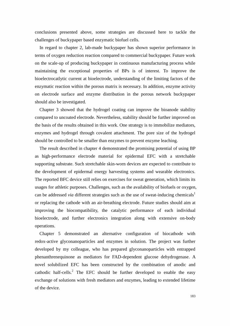
183
conclusions presented above, some strategies are discussed here to tackle the
challenges of buckypaper based enzymatic biofuel cells.
In regard to chapter 2, lab-made buckypaper has shown superior performance in
terms of oxygen reduction reaction compared to commercial buckypaper. Future work
on the scale-up of producing buckypaper in continuous manufacturing process while
maintaining the exceptional properties of BPs is of interest. To improve the
bioelectrocatlytic current at bioelectrode, understanding of the limiting factors of the
enzymatic reaction within the porous matrix is necessary. In addition, enzyme activity
on electrode surface and enzyme distribution in the porous network buckypaper
should also be investigated.
Chapter 3 showed that the hydrogel coating can improve the bioanode stability
compared to uncoated electrode. Nevertheless, stability should be further improved on
the basis of the results obtained in this work. One strategy is to immobilize mediators,
enzymes and hydrogel through covalent attachment. The pore size of the hydrogel
should be controlled to be smaller than enzymes to prevent enzyme leaching.
The result described in chapter 4 demonstrated the promising potential of using BP
as high-performance electrode material for epidermal EFC with a stretchable
supporting substrate. Such stretchable skin-worn devices are expected to contribute to
the development of epidermal energy harvesting systems and wearable electronics.
The reported BFC device still relies on exercises for sweat generation, which limits its
usages for athletic purposes. Challenges, such as the availability of biofuels or oxygen,
can be addressed via different strategies such as the use of sweat-inducing chemicals1
or replacing the cathode with an air-breathing electrode. Future studies should aim at
improving the biocompatibility, the catalytic performance of each individual
bioelectrode, and further electronics integration along with extensive on-body
operations.
Chapter 5 demonstrated an alternative configuration of biocathode with
redox-active glyconanoparticles and enzymes in solution. The project was further
developed by my colleague, who has prepared glyconanoparticles with entrapped
phenanthrenequinone as mediators for FAD-dependent glucose dehydrogenase. A
novel solubilized EFC has been constructed by the combination of anodic and
cathodic half-cells.2 The EFC should be further developed to enable the easy
exchange of solutions with fresh mediators and enzymes, leading to extended lifetime
of the device.

184
References
1. Kim, J. et al. Simultaneous Monitoring of Sweat and Interstitial Fluid Using a Single Wearable
Biosensor Platform. Advanced Science 5, 1800880 (2018).
2. Hammond, J. L. et al. Solubilized Enzymatic Fuel Cell (SEFC) for Quasi-Continuous Operation
Exploiting Carbohydrate Block Copolymer Glyconanoparticle Mediators. ACS Energy Lett. 142–
148 (2018) doi:10.1021/acsenergylett.8b01972.

185
Publications and presentations
Publications
A High Power Buckypaper Biofuel Cell: Exploiting
1,10-Phenanthroline-5,6-dione with FAD-Dependent Dehydrogenase for
Catalytically-Powerful Glucose Oxidation
Andrew. J. Gross, Xiaohong Chen, Fabien Giroud, Caroline Abreu, Alan Le Goff,
Michael Holzinger, Serge Cosnier- ACS catalysis 2017, 7, 4408−4416
DOI: 10.1021/acscatal.7b00738
Redox-Active Glyconanoparticles as Electron Shuttles for Mediated Electron
Transfer with Bilirubin Oxidase in Solution
Andrew. J. Gross, Xiaohong Chen, Fabien Giroud, Christophe Travelet, Redouane
Borsali, Serge Cosnier- J. Am. Chem. Soc 2017, 139, 16076-16079
DOI: 10.1021/jacs.7b09442
Comparison of Commercial and Lab-made MWCNT Buckypaper:
Physicochemical Properties and Bioelectrocatalytic O2 Reduction
Xiaohong Chen, Andrew. J. Gross, Fabien Giroud, Michael Holzinger, Serge Cosnier-
Electroanalysis 2018, 30, 1511−1520
DOI: 10.1002/elan.201800136
Stretchable and flexible buckypaper-based lactate biofuel cell for wearable
electronics
Xiaohong Chen, Lu Yin, Jian Lv, Andrew J. Gross, Minh Le, Nathaniel Georg
Gutierrez, Yang Li, Itthipon Jeerapan, Fabien Giroud, Anastasiia Berezovska, Rachel
K. O’Reilly, Sheng Xu, Serge Cosnier, Joseph Wang- Adv. Funct. Mater. 2019,
1905785
DOI: 10.1002/adfm.201905785
Use of alginate hydrogel coating to improve stability of carbon nanotube
bioanode for glucose oxidation
Manuscript under preparation
Poster presentations
XXIV International Symposium on Bioelectrochemistry and Bioenergetics, High
Power Glucose/O2 Biofuel Cell Constructed from Redox-Embedded Carbon
Nanotube Buckypapers. Xiaohong Chen, Andrew J. Gross, Fabien Giroud, Caroline
Abreu, Alan Le Goff, Michael Holzinger, Serge Cosnier. Lyon, July 2017 (won the
best poster award)

186
Oral communications
Journée de Printemps de la section Rhône-Alpes de la Société Chimique de
France, Preparation of Calcium Alginate Hydrogel Coated Nanostructured Carbon
Electrodes for Improved Bioanode Stability. Xiaohong Chen, Fabien Giroud, Andrew
J. Gross, Serge Cosnier. Lyon, June 2018
Annual Meeting of the doctoral School of Chemistry and Life Sciences,
Bioelectrocatalytic oxidation of different substrates by immobilizing oxidoreductases
onto functionalized buckypapers. Xiaohong Chen, Fabien Giroud, Andrew J. Gross,
Serge Cosnier. Grenoble, June 2018 (flash communication)
XVIème colloque du Groupe Français de Bioélectrochimie, Free-standing
Commercial and Lab-Made Carbon Nanostructured Electrodes for Enzymatic Biofuel
Cells Applications. Xiaohong Chen, Andrew J. Gross, Fabien Giroud, Michael
Holzinger, Serge Cosnier. Sète, September 2018
235th ECS meeting, Redox Active Metallic and Glyco-Based Nanoparticles for
Enzymatic Bioelectrocatalysis. Xiaohong Chen, Jules L Hammond, Andrew J. Gross,
Fabien Giroud, Redouane Borsali, Serge Cosnier. Dallas, TX, May 2019
Research visit during the doctoral program (Dec 2018 – May 2019)
Visiting graduate student in Department of Nanoengineering at University of
California, San Diego (USA) under the supervision of Prof. Joseph Wang.

187
Acknowlegements
My PhD study at BEA has officially come to an end. Whilst the past few years in
France have been very challenging for me, they have become an extraordinary
experience that I will always remember with gratitude. And I would like to take this
opportunity to express my greatest appreciation to those who accompanied me during
this journey.
My deepest gratitude goes first and foremost to my supervisor and co-supervisor:
Dr. Serge Cosnier and Dr. Fabien Giroud for their greatest support on my PhD
fellowship application and giving me the opportunity to conduct research in BEA. I
am grateful for their mentoring, inspiration and full support throughout the past four
years. Most importantly, Serge inspired me to do my best and offered me many
opportunites to participate in conferences and exchange program. Fabien is the one
who is always there for questions, discussions and offerering help in either
professional or personal life. It is their constant support and encouragement that
makes this dissertation possible.
I would like to extend my gratitude to the members of my jury: Dr. Sophie Tingry,
Dr. Carole Chaix, Dr. Laurent Bouffier and Pr. Guy Royal. Thank you for taking the
time and effort to read my dissertation and for the inspiring discussions and useful
advice to improve my dissertation.
I would like to express my sincere appreciation to Dr. Andrew Gross, who guided
me during master internship and continues to help me during my first year to get
familiar with the research. I am also gratefuel for the useful discussion and your help
on correcting my writings.
During my PhD, I was fortunate to be able to work with different collaborators. I
am grateful for the opportunity to work with Dr. Radoune Borsali and Dr. Christophe
Travelet at CERMAV on the glyconanoparticle project.
I am also grateful for the opportunity to work with Pr. Joseph Wang at University of
California, San Diego during my visit. I benefit from the knowledge transfer and
discussion with all the fellows. I thank IDEX for providing the travel grant for
funding this exchange program.
I would like to thank staffs from the department and the doctoral school: Regine
Rozand, Véronique Gineste and Magali Pourtier for their help on the complicated
administrative procedure.

188
I would like to thank all memebers of the BEA group: Dr. Michael Holzinger, Dr.
Karine Gorgy, Yannig Nedellec, Dr. Alan Le Goff, Dr. Chantal Gondran and Arielle
Le Pellec. I am greatful for every colleague for always being nice to me and for your
kind assistance.
I would like to also express sincere thanks to my office buddies: Anastasiia
Berezovska, Dr. Deborah Brazzolotto, Dr. Ilaria Sorrentino, Marie Berthuel, Marie
Carrière, Dr. Jules Hammond, Monica Brachi and Rosanna Puopolo. Thank you for
the company and I will always cherish the laughters we share.
Many thanks to all the friends I met in the past four years: Dr. Hang Yu, Dr. Yang Si,
Nur Istiqomah Khamidy, Zhejian Cao, Dr. Wanxin Tang, Dr. Itthipon Jeerapan, Dr.
Jian Lv, Lu Yin, Songsong Tang, Zhihua Lin, Yuan Du, Dr. Zhanhong Li and
Chochanon Moonla. I am deeply greatful for your company and support.
Finally, I want to express my greatest thanks to my family. Thank you for always
being there.
Xiaohong Chen

189
Bioelectrocatalytic oxidation and reduction of different substrates using carbon nanostructured
electrodes
The aim of this thesis is to explore the formulations, characterizations and practical applications of
buckypapers (BPs) as electrode material for enzymatic biofuel cells (EFCs). The thesis starts with a
general introduction about EFCs in chapter 1. Chapter 2 concerns the comparison of commercial and
laboratory-made BP. Commercial BP is macroporous and possesses higher oxygen content but more
ordered and looser structure with significantly wider diameter nanotubes. Lab-made BP is mesoporous
and possesses 9-times higher specific surface area. The latter also shows superior performance for
oxygen reduction when immobilized with bilirubin oxidase (BOx). The third chapter investigates the
effect of alginate hydrogel coating on bioanode stability for glucose oxidation. The hydrogel coating
was prepared by drop-casting alginate/CaCO3 mixture, followed by addition of gluconolactone to form
uniform hydrogel film by ionic cross-linking. Both operational and storage stability have been
improved compared to the uncoated electrode. The fourth chapter describes a wearable lactate/O2 EFC
by the integration of flexible buckypaper bioelectrodes and a screen-printed stretchable substrate. The
assembled EFC was able to maintain its performance stability under stretching conditions and could
power a LED in both pulse and continuous discharge mode. The last chapter presented the
self-assembly, characterization of redox-active nanoparticles entrapped with mediators. The cathode
could deliver a current density of 4 μA cm−2
with BOx and redox-active nanoparticles in solution.
Keywords: Enzymatic biofuel cell, bioelectrocatalysis, buckypaper, redox mediators, electrochemistry
Oxydation et réduction bioélectrocatalytique de différents substrats à l'aide d'électrodes en
carbone nanostructurées
Le but de cette thèse est d'explorer les formulations, les caractérisations et les applications pratiques
des buckypapers (BPs) en tant que matériau d'électrode pour les biopiles enzymatiques (EFCs). La
thèse commence par une introduction générale sur les EFCs au chapitre 1. Le chapitre 2 concerne la
comparaison des BPs commerciales et de BPs fabriquée en laboratoire. La BP commerciale est
macroporeuse et possède une teneur plus élevée en oxygène mais une structure plus ordonnée et plus
souple avec des nanotubes de diamètre nettement plus large. La BP fabriquée en laboratoire est
mésoporeuse et possède une surface spécifique 9 fois supérieure. Ce dernier présente également des
performances supérieures pour la réduction de l’oxygène lorsqu’il est immobilisé avec la bilirubine
oxydase (BOx). Le troisième chapitre étudie l'effet du revêtement d'hydrogel d'alginate sur la stabilité
de la bioanode pour l'oxydation du glucose. Le revêtement d'hydrogel a été préparé par un mélange
d'alginate/CaCO3 coulé par coulée, puis par addition de gluconolactone pour former un film d'hydrogel
uniforme par réticulation ionique. La stabilité opérationnelle et la stabilité au stockage ont été
améliorées par rapport à l'électrode non revêtue. Le quatrième chapitre décrit un lactate/O2 EFC pour
l’usure par l’intégration de bioélectrodes à godets souples et d’un substrat étirable sérigraphié. L'EFC
assemblé était capable de maintenir sa stabilité de performance dans des conditions d'étirement et
pouvait alimenter une LED en mode de décharge pulsée et continue. Le dernier chapitre a présenté
l'autoassemblage, la caractérisation de nanoparticules rédox-actives piégées avec des médiateurs. La
cathode pourrait délivrer une densité de courant de 4 µA cm-2
avec BOx et des nanoparticules
rédox-actives en solution.
Mots clés: Biopile enzymatique, bioélectrocatalyse, buckypaper, médiateurs rédox, électrochimie