Better place-coding of the fundamental frequency in cochlear implants
9
Better place-coding of the fundamental frequency in cochlear implants Luc Geurts and Jan Wouters Laboratory for Experimental ORL, KULeuven, Kapucijnenvoer 33, B 3000 Leuven, Belgium ~Received 31 October 2002; revised 3 November 2003; accepted 24 November 2003! In current cochlear implant systems, the fundamental frequency F 0 of a complex sound is encoded by temporal fluctuations in the envelope of the electrical signals presented on the electrodes. In normal hearing, the lower harmonics of a complex sound are resolved, in contrast with a cochlear implant system. In the present study, it is investigated whether ‘‘place-coding’’of the first harmonic improves the ability of an implantee to discriminate complex sounds with different fundamental frequencies. Therefore, a new filter bank was constructed, for which the first harmonic is always resolved in two adjacent filters, and the balance between both filter outputs is directly related to the frequency of the first harmonic. The new filter bank was compared with a filter bank that is typically used in clinical processors, both with and without the presence of temporal cues in the stimuli. Four users of the LAURA cochlear implant participated in a pitch discrimination task to determine detection thresholds for F 0 differences. The results show that these thresholds decrease noticeably for the new filter bank, if no temporal cues are present in the stimuli. If temporal cues are included, the differences between the results for both filter banks become smaller, but a clear advantage is still observed for the new filter bank. This demonstrates the feasibility of using place-coding for the fundamental frequency. © 2004 Acoustical Society of America. @DOI: 10.1121/1.1642623# PACS numbers: 43.66.Ts, 43.66.Fe, 43.66.Hg @MRL# Pages: 844 –852 I. INTRODUCTION One of the first steps in sound processors for cochlear implants is a splitting of the audio signal into several fre- quency bands or channels, covering the speech frequency range. Since these bands are relatively broad, individual har- monics of periodic sounds are unlikely to be resolved, result- ing in beats at the output of the filters. These temporal fluc- tuations in the envelope provide information on the fundamental frequency F 0 of the sound. If these fluctuations are still present in the electrical signals that stimulate the auditory nerve, cochlear implantees can use this source of information to detect F 0 differences. Sinusoidally amplitude-modulated pulse trains contain similar fluctuations and the elicited pitch increases with modulation frequency. Some implantees can detect differences in the modulation frequency as small as 2%, the exact value being dependent on the modulation frequency and the subject ~McKay et al., 1994!. Geurts and Wouters ~2001! used synthetic vowels to measure the detectable F 0 difference, and found values be- tween 4% and 13%. In general, the just-noticeable frequency difference increases with frequency, whether the stimuli are pulse trains with varying rate ~Eddington et al., 1978; Shan- non, 1983; Tong and Clark, 1985; Townshend et al., 1987!, amplitude-modulated pulse trains ~McKay et al., 1994!, or synthetic vowels, processed by a sound processor ~Geurts and Wouters, 2001!. The frequency limit above which rate discrimination thresholds are very large or even unmeasur- able lies on the average around 300 Hz ~Eddington et al., 1978; Townshend et al., 1987; McKay et al., 1994!. Al- though this limit is above common values of F 0 for speech sounds, it is far below the upper limit of common F 0’s in music. Pijl and Schwarz ~1995! showed that melody recog- nition is possible with single-electrode pulse trains, but per- formance dropped when the values of the F 0’s in the melody increased. They concluded that temporal cues only are suffi- cient for the mediation of musical pitch with a cochlear im- plant, but mainly for the lower half of the range of F 0 ’s commonly used in music, i.e., up to about 500 Hz. In contrast with a cochlear implant processor, the lowest harmonics are resolved in acoustic normal hearing, and the places of maximal activity along the basilar membrane might also provide F 0 information. It is well known that the lower- resolved harmonics dominate pitch perception. The domi- nance of each harmonic depends on the frequency of the fundamental and on the subject ~Moore, 1997!. Given the broad filters used in a cochlear implant processor, all the harmonics, even the lowest, are unlikely to be resolved. This difference with acoustic normal hearing might contribute to the worse performance of cochlear implantees in pitch- discrimination tasks. In this article, a new filter bank will be suggested, which attempts to improve the place coding of an individual har- monic. The idea is based on a finding of McDermott and McKay ~1994!, stating that two concurrent pulse trains on two adjacent electrodes elicit a single pitch, its value depend- ing on the relative difference between the levels of the pulses on both channels. If both pulse trains sound equally loud when presented separately, then the combined stimulation will yield a pitch lying in between the pitches of the pulse trains on the separate channels. The new filter bank is de- signed in such a way that when a single-frequency compo- nent moves through two adjacent filters, the output of the ‘‘lower’’ filter will gradually drop and the output of the ‘‘higher’’ filter will gradually rise. This filter bank will be compared in a pitch-discrimination task with ‘‘classic’’ fil- ters, having broad, flat passbands, and steep slopes beyond 844 J. Acoust. Soc. Am. 115 (2), February 2004 0001-4966/2004/115(2)/844/9/$20.00 © 2004 Acoustical Society of America
Transcript of Better place-coding of the fundamental frequency in cochlear implants

Better place-coding of the fundamental frequencyin cochlear implants
Luc Geurts and Jan WoutersLaboratory for Experimental ORL, KULeuven, Kapucijnenvoer 33, B 3000 Leuven, Belgium
~Received 31 October 2002; revised 3 November 2003; accepted 24 November 2003!
In current cochlear implant systems, the fundamental frequencyF0 of a complex sound is encodedby temporal fluctuations in the envelope of the electrical signals presented on the electrodes. Innormal hearing, the lower harmonics of a complex sound are resolved, in contrast with a cochlearimplant system. In the present study, it is investigated whether ‘‘place-coding’’ of the first harmonicimproves the ability of an implantee to discriminate complex sounds with different fundamentalfrequencies. Therefore, a new filter bank was constructed, for which the first harmonic is alwaysresolved in two adjacent filters, and the balance between both filter outputs is directly related to thefrequency of the first harmonic. The new filter bank was compared with a filter bank that is typicallyused in clinical processors, both with and without the presence of temporal cues in the stimuli. Fourusers of the LAURA cochlear implant participated in a pitch discrimination task to determinedetection thresholds forF0 differences. The results show that these thresholds decrease noticeablyfor the new filter bank, if no temporal cues are present in the stimuli. If temporal cues are included,the differences between the results for both filter banks become smaller, but a clear advantage is stillobserved for the new filter bank. This demonstrates the feasibility of using place-coding for thefundamental frequency. ©2004 Acoustical Society of America.@DOI: 10.1121/1.1642623#
PACS numbers: 43.66.Ts, 43.66.Fe, 43.66.Hg@MRL# Pages: 844–852
leeenhauluchesthe
nctiode
-nar
esu
-e
uffi--
estthe
ght-mi-the
thehisto
ch-
char-ndnnd-sesudtionede-po-the
-yond
I. INTRODUCTION
One of the first steps in sound processors for cochimplants is a splitting of the audio signal into several frquency bands or channels, covering the speech frequrange. Since these bands are relatively broad, individualmonics of periodic sounds are unlikely to be resolved, resing in beats at the output of the filters. These temporal fltuations in the envelope provide information on tfundamental frequencyF0 of the sound. If these fluctuationare still present in the electrical signals that stimulateauditory nerve, cochlear implantees can use this sourcinformation to detect F0 differences. Sinusoidallyamplitude-modulated pulse trains contain similar fluctuatioand the elicited pitch increases with modulation frequenSome implantees can detect differences in the modulafrequency as small as 2%, the exact value being depenon the modulation frequency and the subject~McKay et al.,1994!. Geurts and Wouters~2001! used synthetic vowels tomeasure the detectableF0 difference, and found values between 4% and 13%. In general, the just-noticeable frequedifference increases with frequency, whether the stimulipulse trains with varying rate~Eddingtonet al., 1978; Shan-non, 1983; Tong and Clark, 1985; Townshendet al., 1987!,amplitude-modulated pulse trains~McKay et al., 1994!, orsynthetic vowels, processed by a sound processor~Geurtsand Wouters, 2001!. The frequency limit above which ratdiscrimination thresholds are very large or even unmeaable lies on the average around 300 Hz~Eddingtonet al.,1978; Townshendet al., 1987; McKay et al., 1994!. Al-though this limit is above common values ofF0 for speechsounds, it is far below the upper limit of commonF0’s inmusic. Pijl and Schwarz~1995! showed that melody recognition is possible with single-electrode pulse trains, but p
844 J. Acoust. Soc. Am. 115 (2), February 2004 0001-4966/2004
ar-cyr-t--
eof
sy.nnt
cye
r-
r-
formance dropped when the values of theF0’s in the melodyincreased. They concluded that temporal cues only are scient for the mediation of musical pitch with a cochlear implant, but mainly for the lower half of the range ofF0’scommonly used in music, i.e., up to about 500 Hz.
In contrast with a cochlear implant processor, the lowharmonics are resolved in acoustic normal hearing, andplaces of maximal activity along the basilar membrane mialso provideF0 information. It is well known that the lowerresolved harmonics dominate pitch perception. The donance of each harmonic depends on the frequency offundamental and on the subject~Moore, 1997!. Given thebroad filters used in a cochlear implant processor, allharmonics, even the lowest, are unlikely to be resolved. Tdifference with acoustic normal hearing might contributethe worse performance of cochlear implantees in pitdiscrimination tasks.
In this article, a new filter bank will be suggested, whiattempts to improve the place coding of an individual hmonic. The idea is based on a finding of McDermott aMcKay ~1994!, stating that two concurrent pulse trains otwo adjacent electrodes elicit a single pitch, its value depeing on the relative difference between the levels of the pulon both channels. If both pulse trains sound equally lowhen presented separately, then the combined stimulawill yield a pitch lying in between the pitches of the pulstrains on the separate channels. The new filter bank issigned in such a way that when a single-frequency comnent moves through two adjacent filters, the output of‘‘lower’’ filter will gradually drop and the output of the‘‘higher’’ filter will gradually rise. This filter bank will becompared in a pitch-discrimination task with ‘‘classic’’ filters, having broad, flat passbands, and steep slopes be
/115(2)/844/9/$20.00 © 2004 Acoustical Society of America

lu-
r-int
er
t
gsio
aesteerrea3asicheanertly
tetez,
luisoudefr
ou
re
re
n
ito
thenceens
n-lteruchal-on-ionac-nc-a
e-re-to
thee of
la-thenceherop
Thency.linesFornter
the cutoff frequencies. This comparison permits an evation of whether the induction of resolved harmonics improves pitch perception of complex stimuli. Also, the impotance of the temporal cue will be evaluated, by comparalgorithms that induce temporalF0 fluctuations in the outpuwith algorithms yielding ‘‘flat’’ output signals.
II. SOUND PROCESSING
In total, four algorithms based on the Continuous Intleaved Sampling~CIS! strategy ~Wilson et al., 1991! areused in the perception experiments. Either the classic ornew filter bank is used, and temporalF0 fluctuations areallowed or not. Each algorithm consists of the followinsteps: bandpass filtering, envelope detection, compresand pulse-train modulation.
A. Bandpass filters
For the classic filter bank, the input signal is sampled10 kHz, as is the case in the clinical LAURA speech procsor. The filter bank consists of seven or eight bandpass filthe number varying among participating subjects. The filtare eighth-order Butterworth bandpass filters with cutoff fquencies of 100, 325, 550, 775, 1125, 1634, 2372, 3444,4999 Hz in the eight-channel case and 100, 357, 614, 91421, 2161, 3287, and 4999 Hz in the seven-channel cThese values correspond to the settings of the clinLAURA processors of the participants. Approximately, tfilters are equally spaced on a linear scale below 1 kHzon a logarithmic scale above. At low frequencies, the filtare relatively broad, which is characteristic for all currenavailable cochlear implant systems.
For the new filter bank, referred to as the triangle filbank, the input signal is sampled at 16 kHz, and at lastages in the process further subsampled to 8 kHz, 4 kHkHz, 1 kHz, and 500 Hz~see below!. This filter bank isdesigned to resolve the first harmonic of a complex stimuin two adjacent filters. Ideally, the width of each filtermaximum one octave, meaning that the filter response shbe zero at and below the lowest boundary frequency, anand above twice this frequency. The maximum responsobtained half an octave above or below each boundaryquency. This maximum will be set to 1~0 dB!.
The filter is based on a simple loudness model for nmal hearing. It is designed such that the loudness of a ptone sweeping through the filter increases linearly with fquency from the lower boundary frequencyf BL to the centerfrequency f C , and decreases linearly from the center fquency to the upper boundary frequencyf BH
L5k1•~ f 2 f BL! for f BL< f < f C , ~1!
L5k1•~ f BH2 f ! for f C< f < f BH . ~2!
According to Stevens’ law, loudness is proportional to intesity to the power 0.3~Stevens, 1957!
L5k2•I 0.3. ~3!
This implies that, for a normal-hearing subject, the intensof a pure tone passed through the filter should be prop
J. Acoust. Soc. Am., Vol. 115, No. 2, February 2004 L. Geurts a
a-
g
-
he
n,
t-
rs,s-nd4,e.
al
ds
rr2
s
ldatise-
r-re-
-
-
yr-
tional to the frequency differencef 2 f BL ~or f 2 f BH) to thepower 10/3
I 5k3•~ f 2 f BL!10/3 for f BL< f < f C , ~4!
I 5k3•~ f BH2 f !10/3 for f C< f < f BH . ~5!
Since intensity is the square of amplitude, the gain inpassband should be proportional to the frequency differeto the power 5/3. The constant of proportionality is chossuch that the gain is 1 at the center frequency. This yield
gain5S f 2 f BL
f C2 f BLD 5/3
for f BL< f < f C , ~6!
gain5S f 2 f BH
f C2 f BHD 5/3
for f C< f < f BH . ~7!
Note that this formula is also applicable to cochlear implatees. At this stage the processing is still linear, and the fisimply adjusts the amplitude of an acoustical stimulus, sthat its loudness varies linearly with frequency for a normhearing subject. In a later stage, the amplitude will be nlinearly mapped to a current, using a compression functthat takes the loudness growth of electrical hearing intocount. In the ideal case of a perfect loudness growth fution, the loudness will also vary linearly with frequency forcochlear implantee.
Adjacent filters overlap considerably. The center frquency of a filter corresponds to the higher boundary fquency of the adjacent filter at the low-frequency side, andthe lower boundary frequency of the adjacent filter athigh-frequency side. Figure 1 gives the desired responstwo adjacent filters~circles or squares! and their approxima-tion ~solid lines!. The horizontal axis denotes frequency retive to half the sampling rate. The center frequencies offilters are 0.44 and 0.62 times half the sampling rate. Siloudness varies linearly with frequency according to tmodel, a frequency increase should result in a loudness d
FIG. 1. The frequency characteristics of two adjacent triangular filters.horizontal axis denotes frequency relative to half the sampling frequeThe circles and the squares indicate the desired response. The solidshow the response of the eventually used implementation of the filters.the lowest sampling frequency of 500 Hz used in the experiments, the cefrequencies correspond to 110 and 155 Hz.
845nd J. Wouters: Better place-coding of F0 in cochlear implants

wh
e
ethB.ee
ls
f
athhir
errmcceer
re
d
ath
heheeionsa
es-o
rreefot
ve
u
oth
n-eseDDoneints
lsTheithn theThe
ntalfor
issors.
in the lower filter and an equal and opposite loudness groin the higher filter. The ideal response is approximated wit16th-order infinite impulse response~IIR! filter, using theMATLAB 1 implementation of a modified Yule–Walker routin~Friedlander and Porat, 1984!. The true filter gain is233 and240 dB at the lower and higher boundary frequency, resptively. In the stop band, defined as the region beyondzeros~2` dB! of the filter, the attenuation is at least 48 d
The full filter bank is implemented using a so-called trstructure. The outputs of the two highest filters~Fig. 1! arecalculated, at a sample rate of 16 kHz. The input signal agoes through a third ‘‘antialiasing’’ filter~seventh-order el-liptic low-pass filter! before it is sampled down by a factor o2. Next, the combined process of three filter operationsrepeated another five times. In the last stage, the lowest spling frequency is 500 Hz, and the center frequencies ofcorresponding triangular filters are 110 and 155 Hz. In tway, 12 filters are created. Unfortunately, the LAURA paticipants only have seven or eight available channels. Thfore, several pairs of the highest filters are combined to foone filter with a flat passband between the center frequenof the individual filters. This implies that the intended placoding of frequency will not work properly at those highfrequencies. Yet, the principle can easily be extendedhigher frequencies if enough channels are available. Figushows the frequency characteristics of both filter banks~clas-sic and triangle! in the eight-channel case. Note the broaflat passbands in the classic filter bank.
B. Envelope detection, compression, and pulsemodulation
In the next stage, the envelopes of the filter outputsderived using a rectifier and a fourth-order low-pass smooing filter. To obtain an envelope withoutF0 fluctuations, afull-wave rectifier is used, and the cutoff frequency of tsmoothing filter is set to 20 Hz. This will be referred to as tflat condition. Clear temporalF0 fluctuations in the envelopare obtained if a half-wave rectifier is used in combinatwith a cutoff frequency of 250 Hz. This will be referred to athe temp condition, and results in modulation depthswhich maximum pitch discrimination scores are obtain~Geurts and Wouters, 2001!. The envelope is compressed uing a logarithmic function, such that an envelope valuezero is mapped to the current threshold level of the cosponding electrode channel, and the maximum envelopthe most comfortable level. These levels are obtainedeach channel before the experiments start. According toCIS strategy, all envelopes are modulated with interleapulse trains. The biphasic pulses have a pulse width of 40msper phase, and are stimulated on bipolar channels. The prate is either 1250 pps~8 channels! or 1429 pps~7 channels!,yielding an overall pulse rate of 10 000 pps.
III. EXPERIMENT
A. Subjects
Four postlingually deafened users of the LAURA2 co-chlear implant participated in this study. Some details abthe subjects can be found in Table I. Two versions of
846 J. Acoust. Soc. Am., Vol. 115, No. 2, February 2004 L. G
tha
c-e
o
ism-es-e-
ies
to2
,
re-
td
f-tor
hed
lse
ute
electrode array of the LAURA implant exist, and both cosist of eight bipolar electrode pairs, called channels. Thare numbered from apex to base. Subjects SV, JH, anduse type 5.6: the distance between the two electrodes ofchannel is 1.3 mm, and the distance between the midpo
FIG. 2. The frequency characteristics of the classic filter bank~above! andthe new triangle filter bank~below! in the case that eight electrode channeare available. The classic filter bank contains somewhat broader filters.four highest pairs of triangular filters are combined to four single filters wa flat passband between the center frequencies of the individual filters. Iseven-channel case, also filters three and four are combined similarly.symbols below the horizontal axis indicate the values of the fundamefrequencies of the standard stimuli of the different conditions: diamondsseven-channel stimuli, plus-signs for eight-channel stimuli.
TABLE I. Some details of the four LAURA subjects who participated in thstudy. The same channels are used daily in the subjects’ clinical proces
SubjectAge~yrs!
Durationof
profounddeafness
~yrs! Etiology
Implantexperi-ence~yrs!
Numberof activeelectrodechannels
DD 36 1 Trauma 6 7WM 51 5 Progressive 4 7JH 20 3 Meningitis 7 7SV 33 6 Unknown 7 8
eurts and J. Wouters: Better place-coding of F0 in cochlear implants

sehipn
e
enonai
r,go
ed
ond,50
d innteewith
ch-owntalpli-
but-andc-
the/a/,ves
for-ic
asnd.a
250
of adjacent channels is 2.05 mm. For subject WM, who utype 5.8, these values are, respectively, 2 and 3 mm, wmeans that his channels physically overlap. Both array tyare schematically presented in Fig. 1 of van Wieringen aWouters~1999!.
B. Stimuli
All stimuli were synthetic vowels, created using thKlatt synthesizer available in theCSRE software package.3
The duration of the stimuli was 500 ms, and a sample rat20 kHz was chosen. The formant frequencies and bawidths corresponded either to /a/ or /i/, and were kept cstant for all fundamental frequencies. The exact valuestypical for Flemish/Dutch spoken language and are givenTable II ~Govaerts, 1978!. When using the Klatt synthesizethe value of the fundamental period has to equal an intemultiple of the sampling period. The fundamental periodthe synthesized vowels ranged from 2.7 ms (F05370 Hz) to10.0 ms (F05100 Hz).
TABLE II. Formant frequencies (Fi ) and bandwidths (Bi) in Hz of thesynthetic vowels used in experiment II~Govaerts, 1978!.
Vowel F1 B1 F2 B2 F3 B3 F4 B4 F5 B5
/a/ 890 110 1360 120 2475 160 3530 275 4830 3/i/ 225 40 2280 90 2820 120 3200 120 3500 15
J. Acoust. Soc. Am., Vol. 115, No. 2, February 2004 L. Geurts a
schesd
ofd--ren
erf
After the synthesis, the stimuli were further processusing custom-madeMATLAB functions. The first 100 ms weretruncated to excise the nonzero dc level at the onset. Secthe vowels were gated at the initial 50 ms and at the finalms, using a cosine ramp. Finally, all vowels were balanceroot-mean-square level. Note that this does not guarathat loudness cannot be used as a cue when two vowelsdifferent F0 must be discriminated.
Eventually, these stimuli were processed by the speeprocessing algorithms. For this study, it is of interest to knhow the energy in each channel varies with the fundamefrequency of the vowel. Figure 3 shows the average amtude in each of the first three channels as a function ofF0,obtained after bandpass filtering and envelope detection,before compression~see supra!. Note that this amplitude corresponds to the steady-state value in the flat condition,that this value is proportional to the mean value of the flutuating envelope in the temp condition. The upper andlower plots correspond to the results for the vowel /i/ andrespectively. Note the typical triangular shape of the curfor the triangle filter bank~right plots!. It is clear that thechannel outputs could provide a consistent source of inmation on the value ofF0. This is not the case for the classfilter banks, where the energy either hardly changes withF0or fluctuates in an inconsistent and unpredictable way,long as the fundamental component is within the passbaFrom this, it is predicted that it is more difficult to deriveconsistent cue on the value ofF0.
FIG. 3. The average amplitude in the first three channels~out of eight! as a function of the fundamental frequency for the vowels /a/~upper plots! and /i/~lower plots!. The left plots are the results for the classic filter bank, the right plots for the triangle filter bank.
847nd J. Wouters: Better place-coding of F0 in cochlear implants

ep
net otr
ight
sed
r,her
89lueels.Fig.theatss-e
tal:
asinth
The data for the triangle filter bank are further analyzby calculating the ratio of the average uncompressed amtudes of channel 1 and 2 as a function ofF0 between thecenter frequencies of both channels. Since this ratio odepends on the frequency of the fundamental componand not on its amplitude, it is almost perfectly independenspectral shape, as shown in Fig. 4. So, the new coding s
FIG. 4. The ratio of the average uncompressed amplitudes of channel 12 as a function ofF0 between the center frequencies of both channels uthe triangle filter bank. The circles indicate the values for the vowel /a/,crosses for the vowel /i/.
848 J. Acoust. Soc. Am., Vol. 115, No. 2, February 2004 L. G
dli-
lynt,f
at-
egy seems to provide a consistent physical cue, which mbe used by implantees.
C. Method
To estimate the smallest difference inF0 that could bediscriminated, a 2-down, 1-up adaptive procedure was u~Levitt, 1971!. Two vowels with differentF0, further calledthestandardand thesignal, were presented in random ordeand the subject had to indicate the stimulus with the higpitch.4 Correct response feedback was not given.F0 of thestandard stimulus was fixed to either 110, 145, 172, or 1Hz for the subjects using seven channels. The latter vawas changed to 263 Hz for the subject using eight channThese frequencies are indicated on the horizontal axis of2. They were chosen such that different segments ontriangular shape were ‘‘visited’’ during the tests: at the top,the crossings of neighboring filters, and in between the croings. Note that all these values fall within the first filter of thclassic filter bank. Hence, there were 32 conditions in totwo phonemes~/a/ and /i/!, four standardF0’s, and fouralgorithms,5 and each condition was tested once.
For the first trial, theF0 of the signal was at least 40%above theF0 of the standard, except for the highestF0 of263 Hz for which the signal’sF0 started at 333 Hz~127%!.
ndge
ynthetica limitted are not
FIG. 5. The just-noticeableF0 difference~jnd! for different values of the standardF0 for subject DD, using the classic filter bank~squares! or the new filterbank~triangles!. The left plots show the results for the stimuli without temporal cues, the right plots those for the stimuli with temporal cues. The svowel was /a/ or /i/~respectively, upper and lower plots!. A diamond in a symbol indicates that the adaptive procedure was diverging. Since there wason the largestF0 difference presented, the obtained value is an underestimate of the real noticeableF0 difference. The small gray horizontal lines indicathe relativeF0 values of all stimuli that could be visited in the adaptive procedure. For clarity, the lines connect points within the same condition anintended to represent a relationship betweenF0 and the jnd.
eurts and J. Wouters: Better place-coding of F0 in cochlear implants
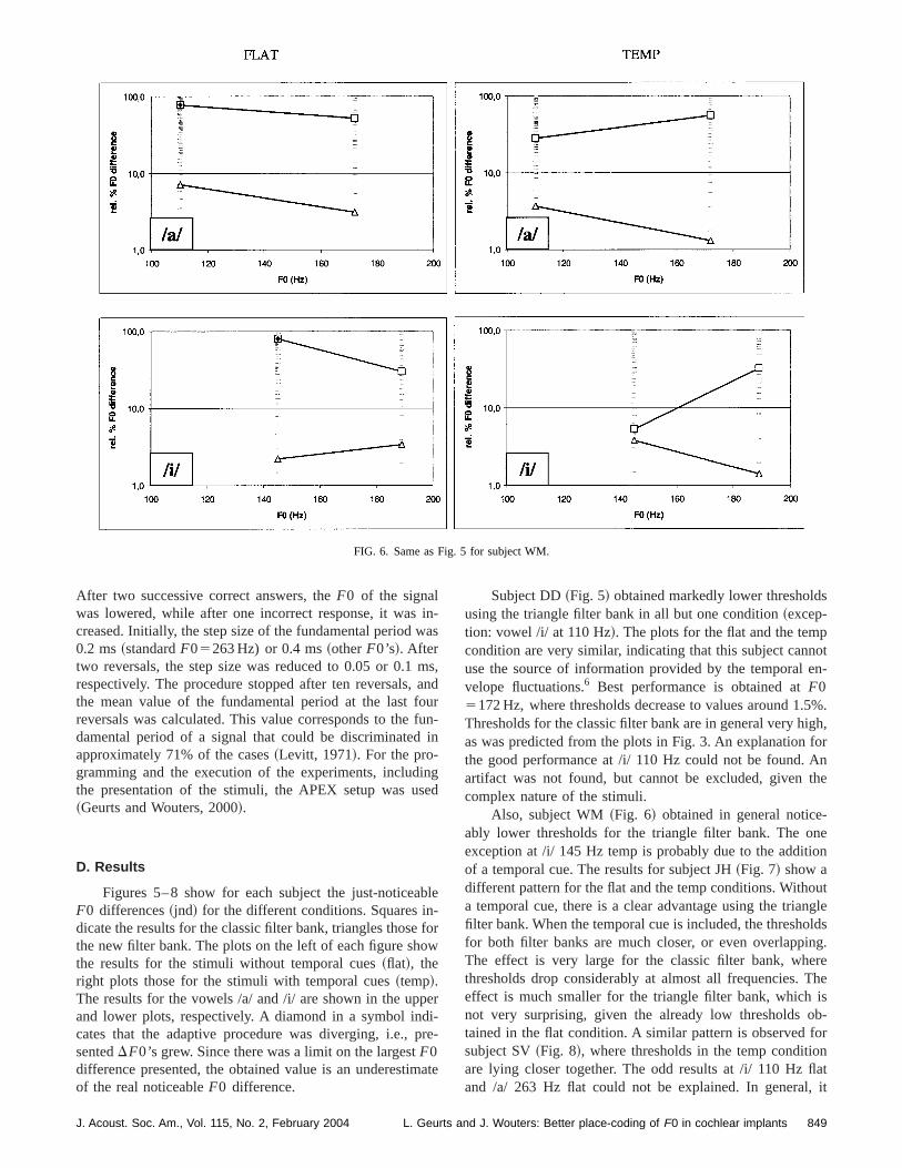
FIG. 6. Same as Fig. 5 for subject WM.
inwa
ma
oufui
inse
b-f
ow
pedi-pr
s
pot
en-
.5%.gh,forAnthe
-neion
utnglelds
ng.reTheisb-ornflat, it
After two successive correct answers, theF0 of the signalwas lowered, while after one incorrect response, it wascreased. Initially, the step size of the fundamental period0.2 ms~standardF05263 Hz) or 0.4 ms~otherF0’s!. Aftertwo reversals, the step size was reduced to 0.05 or 0.1respectively. The procedure stopped after ten reversals,the mean value of the fundamental period at the last freversals was calculated. This value corresponds to thedamental period of a signal that could be discriminatedapproximately 71% of the cases~Levitt, 1971!. For the pro-gramming and the execution of the experiments, includthe presentation of the stimuli, the APEX setup was u~Geurts and Wouters, 2000!.
D. Results
Figures 5–8 show for each subject the just-noticeaF0 differences~jnd! for the different conditions. Squares indicate the results for the classic filter bank, triangles thosethe new filter bank. The plots on the left of each figure shthe results for the stimuli without temporal cues~flat!, theright plots those for the stimuli with temporal cues~temp!.The results for the vowels /a/ and /i/ are shown in the upand lower plots, respectively. A diamond in a symbol incates that the adaptive procedure was diverging, i.e.,sentedDF0’s grew. Since there was a limit on the largestF0difference presented, the obtained value is an underestimof the real noticeableF0 difference.
J. Acoust. Soc. Am., Vol. 115, No. 2, February 2004 L. Geurts a
-s
s,ndrn-n
gd
le
or
r
e-
ate
Subject DD~Fig. 5! obtained markedly lower thresholdusing the triangle filter bank in all but one condition~excep-tion: vowel /i/ at 110 Hz!. The plots for the flat and the temcondition are very similar, indicating that this subject cannuse the source of information provided by the temporalvelope fluctuations.6 Best performance is obtained atF05172 Hz, where thresholds decrease to values around 1Thresholds for the classic filter bank are in general very hias was predicted from the plots in Fig. 3. An explanationthe good performance at /i/ 110 Hz could not be found.artifact was not found, but cannot be excluded, givencomplex nature of the stimuli.
Also, subject WM~Fig. 6! obtained in general noticeably lower thresholds for the triangle filter bank. The oexception at /i/ 145 Hz temp is probably due to the additof a temporal cue. The results for subject JH~Fig. 7! show adifferent pattern for the flat and the temp conditions. Withoa temporal cue, there is a clear advantage using the triafilter bank. When the temporal cue is included, the threshofor both filter banks are much closer, or even overlappiThe effect is very large for the classic filter bank, whethresholds drop considerably at almost all frequencies.effect is much smaller for the triangle filter bank, whichnot very surprising, given the already low thresholds otained in the flat condition. A similar pattern is observed fsubject SV~Fig. 8!, where thresholds in the temp conditioare lying closer together. The odd results at /i/ 110 Hzand /a/ 263 Hz flat could not be explained. In general
849nd J. Wouters: Better place-coding of F0 in cochlear implants
FIG. 7. Same as Fig. 5 for subject JH.
orfla
tet
ththn
no
foh
ptoc
se
tero
ac-theis
ter.e-
po-w-si-lan-heger
hen
atm-an
thecies
ofThetimaledof
re
seems that a large improvement by inclusion of the tempcue is obtained only if thresholds are very poor in thecondition.
The data were analyzed using a four-factorial repeameasures analysis of variance~ANOVA !. The independenvariables were filter bank~classic or triangle!, presence oftemporal fluctuations~flat or temp!, vowel ~/a/ or /i/!, andstandardF0 frequency~low or high!. Since subject WMcompleted the tests at only two frequencies, the data at ofrequencies for the other subjects were not included inanalysis. The main effect of the filter bank was significa(p50.002). The main effects for the other factors weresignificant: presence of temporal fluctuation (p50.135),vowel (p50.398), and standardF0 frequency (p50.348).Only one interaction term was significant: vowel3standardF0 frequency (p50.031).
To summarize, from the total of 56 measurementseach filter bank, the triangle filter bank outperformed tclassic filter bank in 41 cases~flat: 25/28, temp: 16/28!. If theresults were separated less than two steps in the adatracking, performance was judged to be equal, whichcurred 11 times~flat: 1/28, temp: 10/28!. The results for theclassic filter bank were better in four cases~flat: 2/28, temp:2/28!. Also note that thresholds were below 2.5% in 15 caof the triangle filter bank~never for the classic filter bank!.
IV. DISCUSSION
There are two main differences between the two filbanks—the filter shape and the cutoff frequencies—and f
850 J. Acoust. Soc. Am., Vol. 115, No. 2, February 2004 L. G
alt
d-
erett
re
ive-
s
rm
the experiments it cannot be concluded which of those ftors contributed the most to the better performance fortriangle filter bank. It is obvious that the classic filter bankdisadvantaged in the experiments, given the wide first filNote however that this is a common setting for clinical dvices ~Faulkner et al., 2000!. In general, the first filter isbroad and does not always capture the fundamental comnent of a harmonic sound, due to the relatively high locutoff frequency, while the experiments illustrate the feability of using ‘‘place-coding’’ for the fundamentafrequency. The triangle filter bank uses more electrode chnels for the lowest frequencies, thereby ‘‘smearing out’’ tplace coding of the fundamental component over a larrange in the cochlea: the sameDF0 will result in a largerdifference in place of maximal excitation in the cochlea.
Regarding the filter shape, care should be taken wusing a ‘‘rectangular’’ filter instead of a ‘‘triangular’’ filter.Analysis for the vowel /a/ as shown in Fig. 3 revealed thusing the cutoff frequencies of the triangle filter bank, cobined with a rectangular Butterworth shape, results inirregular pattern, as shown in Fig. 9. The effect is due tocomplex interplay between harmonics, resonant frequenused for vowel synthesis, the root-mean-square levelingthe vowels, and the bandpass filters of the CIS strategy.nonmonotonic behavior in the passband suggests subopperformance in a pitch-discrimination task, as is illustratby the results of the experiments. This justifies the choicea triangular shape.
A potential problem is that two different percepts a
eurts and J. Wouters: Better place-coding of F0 in cochlear implants

FIG. 8. Same as Fig. 5 for subject SV.
,an--ah
in-fo
enin
lantgap
ghro--tedofeech
a. 3
notction
theneit
itch
x-ar-orealler.w-of
. 3
used to provide information onF0: rate and place pitchwhich can be varied independently in a cochlear impl~McKay et al., 2000!. Yet, in normal hearing both mechanisms play a role: ifF0 rises, the excitation pattern of resolved harmonics shifts basally and the nerve fibersphase-locked to higher frequencies. Which of these mecnisms is the most dominant is still the subject of an ongodebate~Moore, 1997!. In currently available cochlear implant systems, place-coding is solely used to provide inmation on spectral shape. If place-coding is also usedencodeF0, confusion may arise when bothF0 and the spec-tral shape are changing, certainly if there is a lack of extsive training and/or experience with the new coding. Aga
FIG. 9. The average amplitude in the first three channels~out of eight! as afunction of the fundamental frequency for the vowel /a/, similar as in FigThe filters have a rectangular shape~Butterworth! as in the classic filterbank, but the cutoff frequencies are those of the triangle filter bank.
J. Acoust. Soc. Am., Vol. 115, No. 2, February 2004 L. Geurts a
t
rea-g
r-to
-,
this also happens in normal hearing, and a cochlear impsystem should mimic both mechanisms to narrow thebetween normal acoustic hearing and electric hearing.
The proposed method should also work for very hiF0’s, in the range where temporal mechanisms fail to pvide information onF0. This temporal limit lies on the average around 300 Hz. Unfortunately, this could not be teswith the participating subjects, given their limited numberchannels. At least 12 channels are needed to cover the spfrequency range with triangular filters~see Fig. 2!. However,since all triangular filters are identical when plotted onlogarithmic scale, the observed output patterns as in Figwill simply shift to more basal electrodes for higherF0’s.So, as long as electrode discrimination ability doeschange noticeably, subjects should have the same detelimits at highF0’s when using the triangle filter bank.
The triangle filter bank presented here only resolvesfirst harmonic of a complex sound, since all filters are ooctave wide. From experiments with normal hearing,seems that higher harmonics are more dominant for pperception~Moore, 1997; Dai, 2000!, so smaller detectionlimits might be obtained if the triangle filter bank was etended to resolve higher harmonics. However, if more hmonics should be resolved, more filters—and thus melectrodes—are needed, and these filters should be smThe necessary filter width can be calculated using the folloing formula, in which NRH corresponds to the number
.
851nd J. Wouters: Better place-coding of F0 in cochlear implants

s
h
ha
galdnilteic
mger
Id
ay
m
-enelpstr
hec
o
waeln
h
estwaseysem-o use
ore
ncelse250
tion
h
.,el.
-m.
’’ J.
jke
J.
’ J.
im-
ins
’’ J.
c.
.
resolved harmonics, andf BL and f BH to the lower and higherboundary frequencies, respectively:
relative filter width5f BH
f BL521/NRH. ~8!
As a consequence, the required number of filters increalinearly with the desired number of resolved harmonics~12filters to resolve the first harmonic, 24 filters to resolve tsecond as well, ...!. The experiments show, however, thatF0differences can already be detected by resolving the firstmonic only.
V. CONCLUSIONS
The experiments illustrate the feasibility of usin‘‘place-coding’’ to provide information on the fundamentfrequency of a complex sound, including speech sounThis place-coding is achieved by resolving the first harmoin two adjacent filters, while the balance between both fioutputs is directly related to the frequency of the harmonThe results show that detection thresholds forF0 differencesin general decrease noticeably for the new filter bank, copared to a commonly used filter bank, and the effect is larif no temporal cues are present in the stimuli. Differencbetween the results for both filter banks become smallethe envelopes of the stimuli fluctuate according toF0, but aclear advantage is still observed for the new filter bank.summary, the concept of the new filter bank can be usecurrent cochlear implant systems, thereby providing informtion on F0, supplementary to the information provided bthe temporal envelope fluctuations.F0 difference detectionlimits will decrease, certainly at high frequencies where teporal cues will fall short.
ACKNOWLEDGMENTS
We would like to thank all subjects for their participation and Dr. Astrid van Wieringen for running part of thexperiments. We also want to show gratitude to Koen Eman from the ESAT laboratory of the KULeuven for his hein the filter design, Johan Laneau for his help in the statical analysis, and Andrew Faulkner and an anonymousviewer for their comments on the previous version of tmanuscript. This study was supported by the Fund for Sentific Research—Flanders~Belgium!, and partly by an OTproject of the Research Fund of the KULeuven.
1MATLAB is a registered trademark of The Mathworks, Inc.~http://www.mathworks.com!
2LAURA was a registered trademark of Philips Hearing Implants, now Cchlear.
3COMPUTERISED SPEECH RESEARCH ENVIRONMENT, Version 4.5, AVAAZ Inno-vations, Inc.~http://www.avaaz.com!
4The procedure was altered for subject DD. From a prior experiment itrevealed that electrode 4, used for CIS channel 3 in the experiments,ited a lower pitch than the deeper inserted electrode 3, used for CIS cha2 ~tonotopical order!. This could result in a ‘‘cue reversal:’’ a stimulus wita low F0 can sound higher than a stimulus with a highF0. Therefore, the
852 J. Acoust. Soc. Am., Vol. 115, No. 2, February 2004 L. G
es
e
r-
s.cr.
-ersif
nin-
-
-
i-e-
i-
-
sic-nel
subject was initially instructed to indicate the stimulus with the highpitch, as for the other subjects. However, if the adaptive procedurediverging consistently (DF0 grows!, the experiment was restarted with thinstruction to indicate the stimulus with the lowest pitch. This alwayielded a converging adaptation path. There was no conflict with the tporal cue for this subject, since the results reveal that he did not seem tthe temporal cue~see further, Fig. 5!.
5Subject WM only completed 16 conditions, due to an implant failure befall experiments could be carried out.
6This was confirmed in a prior experiment, where he performed at chalevel when differentiating two sinusoidally amplitude-modulated putrains on one electrode channel with modulation frequencies of 150 andHz. The other subjects already had experience with pitch-discriminatasks~Geurts and Wouters, 2001!.
Dai, H. ~2000!. ‘‘On the relative influence of individual harmonics on pitcjudgment,’’ J. Acoust. Soc. Am.107, 953–959.
Eddington, D. K., Dobelle, W. H., Brackman, D. E., Mladejovsky, M. Gand Parkin, J. L.~1978!. ‘‘Auditory prostheses research with multiplchannel intracochlear stimulation in man,’’ Ann. Otol. Rhinol. LaryngoSuppl.87, Suppl. 53, 1–59.
Faulkner, A., Rosen, S., and Smith, C.~2000!. ‘‘Effects of the salience ofpitch and periodicity information on the intelligibility of four-channel vocoded speech: Implications for cochlear implants,’’ J. Acoust. Soc. A108, 1877–1887.
Friedlander, B., and Porat, B.~1984!. ‘‘The modified Yule–Walker methodof ARMA spectral estimation,’’ IEEE Trans. Aerosp. Electron. Syst.AES-20, 158–173.
Geurts, L., and Wouters, J.~2000!. ‘‘A concept for a research tool for ex-periments with cochlear implant users,’’ J. Acoust. Soc. Am.108, 2949–2956.
Geurts, L., and Wouters, J.~2001!. ‘‘Coding of the fundamental frequency incontinuous interleaved sampling processors for cochlear implants,Acoust. Soc. Am.109, 713–726.
Govaerts, G.~1978!. ‘‘Perceptuele structuren van synthetische en natuurliklinkers,’’ Psychologica Belgica18-1, 27–67.
Levitt, H. ~1971!. ‘‘Transformed up–down methods in psychoacoustics,’’Acoust. Soc. Am.49, 467–477.
McDermott, H. J., and McKay, C. M.~1994!. ‘‘Pitch ranking with non-simultaneous dual-electrode electrical stimulation of the cochlea,’Acoust. Soc. Am.96, 155–162.
McKay, C. M., McDermott, H. J., and Clark, G. M.~1994!. ‘‘Pitch perceptsassociated with amplitude-modulated current pulse trains in cochlearplantees,’’ J. Acoust. Soc. Am.96, 2664–2673.
McKay, C. M., McDermott, H. J., and Carlyon, R. P.~2000!. ‘‘Place andtemporal cues in pitch perception: Are they truly independent?’’ ARLO1,25–30.
Moore, B. C. J.~1997!. An Introduction to the Psychology of Hearing, 4thed. ~Academic, New York!, edition.
Pijl, S., and Schwarz, D. W. F.~1995!. ‘‘Melody recognition and musicalinterval perception by deaf subjects stimulated with electrical pulse trathrough single cochlear implant electrodes,’’ J. Acoust. Soc. Am.98, 886–895.
Shannon, R. V.~1983!. ‘‘Multichannel electrical stimulation of the auditorynerve in man. I. Basic psychophysics,’’ Hear. Res.11, 157–189.
Stevens, S. S.~1957!. ‘‘On the psychophysical law,’’ Psychol. Rev.64, 153–181.
Tong, Y. C., and Clark, G. M.~1985!. ‘‘Absolute identification of electricpulse rates and electrode positions by cochlear implant patients,Acoust. Soc. Am.77, 1881–1888.
Townshend, B., Cotter, N., Van Compernolle, D., and White, R. L.~1987!.‘‘Pitch perception by cochlear implant subjects,’’ J. Acoust. Soc. Am.82,106–115.
van Wieringen, A., and Wouters, J.~1999!. ‘‘Gap detection in single- andmultiple-channel stimuli by LAURA cochlear implantees,’’ J. Acoust. SoAm. 106, 1925–1939.
Wilson, B. S., Finley, C. C., Lawson, D. T., Wolford, R. D., Eddington, DK., and Rabinowitz, W. M.~1991!. ‘‘Better speech recognition with co-chlear implants,’’ Nature~London! 352, 236–238.
eurts and J. Wouters: Better place-coding of F0 in cochlear implants