Best Of Both Worlds Bus Enhanced Network On Chip (BENoC)
10
Best of Both Worlds: A Bus Enhanced NoC (BENoC) Ran Manevich 1 , Isask'har Walter 1 , Israel Cidon 2 , and Avinoam Kolodny 2 Electrical Engineering Department, Technion – Israel Institute of Technology, Israel 1 {ranman,zigi}@tx.technion.ac.il 2 {cidon,kolodny}@ee.technion.ac.il Abstract While NoCs are efficient in delivering high throughput point-to-point traffic, their multi-hop operation is too slow for latency sensitive signals. In addition, NoCS are inefficient for multicast operations. Consequently, although NoCs outperform busses in terms of scalability, they may not facilitate all the needs of future SoCs. In this paper, the benefit of adding a global, low latency, low power shared bus as an integral part of the NoC architecture is explored. The Bus-enhanced NoC (BENoC) is equipped with a specialized bus that has low and predictable latency and performs broadcast and multicast. We introduce and analyze MetaBus, a custom bus optimized for such low-latency low power and multicast operations. We demonstrate its potential benefits using an analytical comparison of latency and energy consumption of a BENoC based on MetaBus versus a standard NoC. Then, simulation is used to evaluate BENoC in a dynamic non-uniform cache access (DNUCA) multiprocessor system. † 1. Introduction Novel VLSI literature promotes the use of a multi- stage Network-on-Chip (NoC) as the main on-chip communication infrastructure (e.g., [2], [4], [6]). NoCs are conceived to be more cost effective than buses in terms of traffic scalability, area and power in large scale systems [3]. Thus, NoCs are considered to be the practical choice for future CMP (Chip Multi-Processor) and SoC (System on Chip) system communication. The majority of the traffic delivered by the interconnect in SoC and CMP systems involves latency insensitive, point-to-point, large data transfers such as DMA memory replication. However, other kinds of communication should also be facilitated by the interconnect. Examples include L2 cache read requests, invalidation commands for cache coherency, interrupt signals, cache line search operations, global timing and control signals and broadcast or multicast valid recourses query. Although the volume of traffic of these operations is relatively small, the manner in which the interconnect supports them heavily affects the performance of the system due to their latency sensitive nature. While interconnect architectures which solely rely on a network are cost effective in delivering large blocks of data, they have significant drawbacks when other services are required. Multi-hop networks impose inherent multi-cycle packet delivery latency on the time-sensitive communication between modules. Moreover, advanced communication services like broadcast and multicast incur prolonged latency and involve additional hardware mechanisms or massive duplication of unicast messages. Current NoC implementations are largely distributed (borrowing concepts from off-chip networks). We argue that the on-chip environment provides the architect with a new and unique opportunity to use "the best of both worlds" from the on-chip and the off-chip worlds. In particular, communication schemes that are not feasible in large scale networks become practical, since on-chip modules are placed in close proximity to each other. Consequently, we propose a new architecture termed BENoC (Bus-Enhanced Network on-Chip) composed of two tightly-integrated parts: a low latency, low bandwidth specialized bus, optimized for system-wide distribution of control signals, and a high performance distributed network that handles high-throughput data communication between module pairs (e.g., XPipes [2], QNoC [4], AEthereal [6]). We also propose an implementation of a BENoC bus termed MetaBus, optimized for low latency and multicast, that is used throughout the paper. As the bus is inherently a single hop, broadcast medium, BENoC is shown to be more cost-effective than pure network- based interconnect. Fig. 1 demonstrates BENoC for a cache-in-the-middle CMP. In this example, a grid shaped NoC serves point-to-point transactions, while ______________________________________________________________________________ † A preliminary concise version of this work was published in IEEE Computer Architectures Letters, Volume 7, Issue 1, 2008.
Transcript of Best Of Both Worlds Bus Enhanced Network On Chip (BENoC)

Best of Both Worlds: A Bus Enhanced NoC (BENoC)
Ran Manevich1, Isask'har Walter
1, Israel Cidon
2, and Avinoam Kolodny
2
Electrical Engineering Department, Technion – Israel Institute of Technology, Israel 1ranman,[email protected]
2cidon,[email protected]
Abstract
While NoCs are efficient in delivering high
throughput point-to-point traffic, their multi-hop
operation is too slow for latency sensitive signals. In
addition, NoCS are inefficient for multicast operations.
Consequently, although NoCs outperform busses in
terms of scalability, they may not facilitate all the
needs of future SoCs. In this paper, the benefit of
adding a global, low latency, low power shared bus as
an integral part of the NoC architecture is explored.
The Bus-enhanced NoC (BENoC) is equipped with a
specialized bus that has low and predictable latency
and performs broadcast and multicast. We introduce
and analyze MetaBus, a custom bus optimized for such
low-latency low power and multicast operations. We
demonstrate its potential benefits using an analytical
comparison of latency and energy consumption of a
BENoC based on MetaBus versus a standard NoC.
Then, simulation is used to evaluate BENoC in a
dynamic non-uniform cache access (DNUCA)
multiprocessor system.†
1. Introduction
Novel VLSI literature promotes the use of a multi-
stage Network-on-Chip (NoC) as the main on-chip
communication infrastructure (e.g., [2], [4], [6]). NoCs
are conceived to be more cost effective than buses in
terms of traffic scalability, area and power in large
scale systems [3]. Thus, NoCs are considered to be the
practical choice for future CMP (Chip Multi-Processor)
and SoC (System on Chip) system communication.
The majority of the traffic delivered by the
interconnect in SoC and CMP systems involves latency
insensitive, point-to-point, large data transfers such as
DMA memory replication. However, other kinds of
communication should also be facilitated by the
interconnect. Examples include L2 cache read
requests, invalidation commands for cache coherency,
interrupt signals, cache line search operations, global
timing and control signals and broadcast or multicast
valid recourses query. Although the volume of traffic
of these operations is relatively small, the manner in
which the interconnect supports them heavily affects
the performance of the system due to their latency
sensitive nature. While interconnect architectures
which solely rely on a network are cost effective in
delivering large blocks of data, they have significant
drawbacks when other services are required. Multi-hop
networks impose inherent multi-cycle packet delivery
latency on the time-sensitive communication between
modules. Moreover, advanced communication services
like broadcast and multicast incur prolonged latency
and involve additional hardware mechanisms or
massive duplication of unicast messages.
Current NoC implementations are largely distributed
(borrowing concepts from off-chip networks). We
argue that the on-chip environment provides the
architect with a new and unique opportunity to use "the
best of both worlds" from the on-chip and the off-chip
worlds. In particular, communication schemes that are
not feasible in large scale networks become practical,
since on-chip modules are placed in close proximity to
each other. Consequently, we propose a new
architecture termed BENoC (Bus-Enhanced Network
on-Chip) composed of two tightly-integrated parts: a
low latency, low bandwidth specialized bus, optimized
for system-wide distribution of control signals, and a
high performance distributed network that handles
high-throughput data communication between module
pairs (e.g., XPipes [2], QNoC [4], AEthereal [6]). We
also propose an implementation of a BENoC bus
termed MetaBus, optimized for low latency and
multicast, that is used throughout the paper. As the bus
is inherently a single hop, broadcast medium, BENoC
is shown to be more cost-effective than pure network-
based interconnect. Fig. 1 demonstrates BENoC for a
cache-in-the-middle CMP. In this example, a grid
shaped NoC serves point-to-point transactions, while
______________________________________________________________________________
†A preliminary concise version of this work was published in IEEE
Computer Architectures Letters, Volume 7, Issue 1, 2008.

Figure 1. A BENoC-based CMP system - 16
processors and 4x4 L2 caches.
global, time critical control messages are sent using the
bus.
BENoC's bus (e.g. MetaBus) is a synergetic media
operating in parallel with the network, improving
existing functionality and offering new services. In
previous NoC proposals that include a bus (e.g., [10],
[11]) the bus typically serves as a local mechanism in
the interconnect geographical hierarchy. In [11], each
cluster of modules uses a shared bus for intra-cluster
traffic while inter-cluster traffic uses the network. This
way, the delivery of data to short distances does not
involve the multi-hop network. [10] suggests a bus-
NoC hybrid within a uniprocessor system. By replacing
groups of adjacent links and routers with fast bus
segments performance is improved. However, the data
which is delivered over the network is also delivered
over the bus. In contrast, BENoC's bus is used to send
messages that are different than those delivered by the
network, such as control and multicast messages.
This paper also introduces the benefit of BENoC for
facilitation cache access, coherency and search in CMP
systems. In particular the searching for migrating cache
lines in CMP DNUCA (Dynamic Non-Uniform Cache
Architecture). More services of the built-in bus include
NoC subsystem control, multicast, anycast and
convergecast services.
The paper is organized as follows: in Section 2, we
discuss possible usages of the BENoC architecture. In
section 3 we introduce MetaBus – a BENoC custom
bus implementation. MetaBus employs a novel
combination of a tree topology and a power saving
masking mechanism that disables signal propagation
toward unused tree leaves. In section 4 we analyze
MeatBus based BENoC latency and energy
consumption and show its advantage over conventional
NoC. Our latency model is confirmed using a layout
implementation described in this section. In section 5
we analyze the power saving benefits of the masking
mechanism. In section 6 we evaluate the proposed
architecture using network modeler simulation. Section
7 concludes the paper.
2. BENoC Service
BENoC is composed of two tightly related parts: a
packet switched network (e.g., Xpipes[2], QNoC [4],
AEthereal [6]) for point-to-point massive data
transfers, and MetaBus that functions as a low latency
broadcast/multicast/unicast media. MetaBus is used for
NoC subsystem control, propagation of critical signals
and special custom services. In this section we describe
some of the benefits of using BENoC.
2.1 BENoC for latency sensitive signaling
In typical NoC-based systems, packets that traverse
a path of multiple hops suffer from high latency, due
the routers switching and routing delays accumulated
along its way. This latency is often unacceptable for
short but urgent signaling messages required for the
timely operation of the system. This is stated many
times as one of the main obstacles for an early adoption
of a NoC-based architecture. MetaBus, designed for
low bandwidth and short latency, offers a valuable
alternative: urgent messages may be sent over the bus,
traversing only a single arbitration stage. This enables
quick delivery of time critical signals between modules.
2.2 BENoC multicast services
BENoC enables efficient implementation of
advanced communication services. For example, a SoC
may include multiple specialized resources distributed
across the chip (e.g., DSP processors, ALUs,
multipliers, memory banks). A processor may wish to
send a task to one (or more) of these resources. Hence,
the processor needs to know which of them are idle. As
an alternative to extensive probing, BENoC can
integrate an anycast service where a task is delivered
obliviously to one of the idle resources. For instance,
the processor may initiate a bus multicast destined at
"any idle multiplier". In response, idling multipliers
may arbitrate for the bus and send back their ID, while
the data itself is delivered point-to-point over network.
Even more sophisticated buses may include a
convergecast mechanism that facilitates the efficient
collection of acknowledgements or negative responses
back to the initiator. Finally, the most basic service
provided by the bus is a multicast (broadcast)
operation: In order to deliver a message from one
source to a group of (all) destinations using a basic
NoC, the sender needs to generate multiple unicast
messages [5]. While NoCs may include a built-in
multicast mechanism (e.g., [7]), it will fall behind the
simplicity and low latency of the proposed bus.

2.3 BENoC for CMP cache
A broadcast operation is valuable in shared memory
CMP systems. Typically, each of these processors is
equipped with a local (L1) cache and they all share a
distributed L2 cache (Figure 1). In order to facilitate
cache coherency, the system should provide a
mechanism that prevents applications from reading
stale data. More specifically, when a processor issues a
read exclusive (i.e., read for ownership) command to
one of the L2 caches, all other processors holding a
copy of that cache line should invalidate their local
copy, as it no longer reflects the most updated data.
Such invalidation signal is best propagated using a
broadcast/multicast service. As wire latency becomes a
dominant factor, the L1 miss penalty is heavily affected
by the distance between the processor and the L2 cache
bank holding the fetched line. This observation gave
rise to the DNUCA (Dynamic Non-Uniform Cache
Architecture) approach: instead of having a few
statically allocated possible L2 locations, cache lines
are moved towards processors that access them [8], [9].
One of the major difficulties in implementing DNUCA
is the need to lookup cache lines: whenever a processor
needs to conduct a line fill transaction (fetch a line into
its L1 cache), it needs to determine the identity of the
L2 cache bank/processor storing its updated copy. As
described above, in a network-based interconnect, the
line can be looked for using multiple unicast probes.
BENoC offers a more efficient alternative: MetaBus
can be used to broadcast the query to all cache banks.
The particular cache storing the line can acknowledge
the request over the bus and simultaneously send the
line's content over the NoC. As queries include small
meta-data (initiating processor's ID and line's address),
they do not create substantial load on MetaBus.
2.4 BENoC for system management
MetaBus can also facilitate the configuration and
management of the NoC itself. For example, when
changing the system's operation mode ("usecases" in
[12]), the network may need to be configured. Such a
configuration may include updating routing tables,
adjusting link speeds and remapping the system
modules address space. It may also be desirable to shut
off parts of the NoC when they are not used for a long
time in order to save power. Interestingly, although
these operations are not performed during the run-time
of the system, they should be handled with extreme
care, since the configuration of network elements may
interfere. For example, if a configuration packet turns
off a certain link (or a router), other configuration
messages may not be able to reach their destination due
to "broken paths." Similarly, trying to update routing
table while the network is being used to deliver other
configuration messages is problematic. Alternatively,
configuration can be done via MetaBus making the
configuration and management process much simpler.
3. MetaBus implementation
In this section we present MetaBus – a custom bus
for BENoC. The design principles and guidelines are
presented first, followed by bus architecture, control
mechanisms and communication protocol.
3.1 MetaBus Architecture
MetaBus serves as a low-bandwidth complementary
bus aside a high-bandwidth network. Conventional
system busses (e.g. [20], [21], [22]) are too expensive
in terms of area, power and system complexity for the
limited bus tasks in the BENoC architecture. Thus,
MetaBus does not utilize segmentation, spatial reuse,
pipelining, split transactions and other costly
throughput boosting mechanisms. MetaBus should
pose a low, predictable latency communication medium
that outperforms the network in terms of power and
latency for short unicast, broadcast and multicast
transactions.
MetaBus is constructed as a tree (not necessarily
binary or symmetric) with the communicating modules
on its leaves (Fig 2). The bus is comprised of a root
and "bus stations" on the internal vertices of the tree.
Bus access is regulated by the well known Bus Request
(BR) – Bus Grant (BG) interface. For example, if,
module 2 wishes to transmit a metadata packet to
module 9, it issues a bus request that propagates
through the bus stations up to the root. The root
responds with a bus grant that propagates all the way
back. At this stage of the transaction a combinatorial
path between the transmitting module and receiving
modules is built up. When the bus grant is received,
module 2 transmits an address flit that is followed by
data flits. These flits first go up to the root and then are
spread throughout the tree (broadcast) or through
selected branches (unicast or multicast).
A masking mechanism that is mastered by the root
and configured according to the address flit, prevents
the data from reaching unnecessary tree branches and
thus saves power in unicast and multicast transactions.
After the reception of all valid data flits, the receiver
(module 9) releases the bus by an acknowledgement to
the root and a new transaction may take place.

Figure 2. An example of a 9 modules MetaBus.
MetaBus data and its control signals are
synchronized with a bus clock that is connected only to
the root and to the modules in the leaves of the tree.
Bus stations are clocked by a Bus Grant signal from the
level above them.
3.1.1 Arbitration. The proposed bus utilizes a
distributed arbitration mechanism. The BR/BG
interface is used between all bus units including
modules, bus stations and the root. A requesting bus
station, if granted, will pass a BG to one of its
descendant vertices. The arbitration block in the bus
stations (Fig. 3) uses the BG input as a clock for its
edge sensitive arbitration state machine. The proposed
mechanism enables arbitration priorities adjustments by
placing higher priority modules in higher tree levels or
manipulating specific bus stations arbitration logic.
Figure 3. Arbitration and data switch block in a
binary bus station and their connectivity. 3.1.2 Data Path. MetaBus data path is combined of
two parts – from the transmitter to the root and from
the root to the receivers. A combinatorial route
between the data sending module and the root is
established during bus grant and propagates down to
the transmitter by data switches in the bus stations (Fig.
3). From the root down, the data propagates to the
designated recipients and is blocked from arriving to
irrelevant modules by a masking mechanism described
in the next sub-section. Once established, there is a
combinatorial data path between the transmitter and the
receivers. The delay of this path defines the minimum
clock period for the bus.
3.1.3 Masking. In conventional busses, data reach all
the receivers connected to the bus (or to a bus segment)
even in unicast transactions. The masking mechanism's
role is to save power by preventing the data to reach
unnecessary modules.
Figure 4. Masking Concept.
The mask control logic is located in the root and
controls data propagation from the root down using a
dedicated line to every bus station. In Figure 4 module
3 transmits data to modules 1 and 5. Due to masking,
the data do not reach 6 of the 7 non-recipient modules,
saving redundant switching of wires and gates.
3.1.4 Addressing. Unlike conventional system busses,
MetaBus does not include a separate address bus for
simplicity and area reduction. We dedicate the first
word of every transaction for the destination address,
which is consistent with the NoC addressing scheme.
Transactions lengths are either constant or defined by
the sender using an End Of Transaction signal. We
allocate part of the address space to define commonly
used pre-defined multicast sets. For instance if the data
bus width is 8 (K=8) and we have a 64 modules
system, we have 192 possible addresses for pre-defined
multicast sets (one of them is broadcast). This scheme
is similar to the multicast address convention in
Ethernet and IP.
3.1.5 Acknowledge signals. The bus supports two
feedback signals – Ack and Nack. Each module has
active high Ack and Nack outputs that are joined with
AND gates in the bus stations and form a global Ack
and a global Nack that are generated in the root. Since
the bus is acting as a fast, low-bandwidth metadata
transmission medium aside a high bandwidth network,
many of the signals delivered through the bus may
trigger a response through the NoC. The Ack and Nack

may be used to distinguish between the case when the
transmitter is supposed to receive data through the NoC
(Ack) and the case when all the recipients intercepted
the current message and free the bus (Nack).
3.2 State machine and communication protocol
In this sub-section we present a communication
protocol for a variable length transaction bus with a
data valid line. The proposed bus is clocked at the root
and the modules in the leaves. The bus state machine is
implemented in the arbitration unit in the root and is
presented in figure 5. The events sequence starts from
the "Wait for BR" state. As soon as one of the modules
issues a bus request by setting its BR high, one of root's
BR inputs goes high. Root arbitration unit issues a BG
to one of the children that requested the bus according,
for example, to a round robin principle. Once BG is
issued, the root waits for the first word from the
transmitter. This word includes the address of the
receiver or a multicast set and is marked with a data
valid signal. Then, according to address decoding,
mask lines are activated. Following the masking, data is
transmitted until sender sets data valid bit to "0". Next,
the root de-asserts the mask by masking all the bus
again, waits for Ack or Nack, de-asserts BG timed
according to the received acknowledgement type and
passes again to BR wait state.
We dedicate half of the bus clock cycle for
interactions between the modules and the root (bus
grant propagation, address word decoding,
acknowledgement, masking setting, etc.) and a full
clock cycle for data transmission between
communicating modules. Under these assumptions
each transaction requires 3 clock cycles for arbitration,
addressing, masking and acknowledgement processes.
For each transaction we define the transaction latency
as the number of bus clock cycles required from bus
request of the transmitter until the last data word
clocked by the receiver. In the proposed protocol, a K
data words transaction latency is K+2.5 clock cycles.
Figure 5. Bus state machine. * - BG goes low
according to acknowledge type.
4. Latency and power analysis
For simplicity, the NoC (including the NoC part of
BENoC) is assumed to have a mesh topology, where
system modules are square tiles. The following notation
is used: n is The number of modules in the system,
∆V is the logic voltage swing, C0 and R0 are the
capacitance and resistance of wires per millimeter of
length and P is tile size [mm]. The number of global
wire segments between the modules and the root is
denoted by BD, and LW is the data link width in bits.
The minimal clock period for MetaBus is the sum of
all segment latencies along the data path. The NoC
latency is the number of NoC clock cycles required to
complete a given wormhole transaction. Our power
dissipation analysis takes into account the switching of
global wires and their drivers, for both the NoC and
MetaBus. Local logic power dissipation is neglected.
We define inv invR Cτ as the technology time
constant, where Rinv and Cinv are the input capacitance
and the effective output resistance of an inverter.
Assuming that the load capacitance Cdriver at the end of
each wire segment on the bus is a driver of another
identical segment, we get an upper bound for the bus
segment delay [13],[14]:
( )0.7 0.4
Wire DriverWire Driver Wire Wire
Driver
C CT R C R C
C
τ += + +
(1)
If the capacitance driven by the wire is a small gate
such as in a NoC link, the load is negligible, and the
delay becomes:
0.7 0.4Wire Wire Wire
Driver
T C R CC
τ= + (2)
For the latency and energy of transactions in a NoC-
based system, we assume that a broadcast is composed
of multiple unicast messages. Since an average unicast
message has to travel n modules away from the
source, the minimal time to complete the unicast is:
,net uni CiR Nclk Nclk flitsT nN T T N= + (3)
Where TNclk stands for NoC clock period, NCiR for the
router latency in clock cycles and Nflits for the number
of flits per transaction. In Broadcast, we assume that
the first messages are sent to the most distant modules,
and the last ones to the nearest neighbors. We assume
that the source transmits a flit every NoC clock cycle:
,net broad Nclk flitsT n T N≈ ⋅ (4)
Note that the NoC latency approximations used do
not account for network congestion, and thus, may
underestimate the realistic values.
Assuming a NoC link is P millimeters long, its
resistance and capacitance are 0NLR P R= ⋅ and
0NLC P C= ⋅ . We use (2) to find the appropriate NoC

driver strength CND. Therefore, the NoC link delay is
equal to one half of NoC clock cycle under the
assumption that between two routers, data is sent and
received on opposite network clock edges. The input
capacitance of the routers is neglected since this is a
capacitance of a driver that drives an internal logic, and
therefore is small. We get:
0.7
0.5 0.4
NLND
Nclk NL NL
CC
T R C
τ=
−
(5)
In order to calculate the total energy required for
NoC broadcast, the number of packet transmissions is
determined. In a regular mesh, a source node may have
at most 8 modules at a distance of one, 16 modules two
hops away, 24 modules three hops away and so on. In
the energy-wise best case, the broadcasting module is
located exactly in the middle of the mesh. It therefore
has to send 8 messages that would each travel a single
link each, 16 messages that travel two links, and in
general, 8j messages to a distance of j hops, until
transmitting a total of n-1 messages. It can be easily
shown that if n is an integral, odd number, then the
Manhattan distance between the module in the middle
of the mesh and the ones in its perimeter is exactly
( )max 1 / 2D n= − . Since a message transmitted to a
destination j hops away has to traverse j router-to-
router links, the minimal number of transmissions
required to complete the broadcast is max
2max max
0
8 1 16 2 24 3 ... 8 8D
j
K D D j=
= ⋅ + ⋅ + ⋅ + + ⋅ = ∑ (6)
Consequently, the lower bound of the total energy
consumed by a single broadcast operation would be:
( )2net flits NL NDE V N K C C= ∆ + (7)
An average network unicast transaction would
comprise of ( )max 1 / 2D n= − hops, therefore:
( )( )2
,
1
2net uni flits W NL ND
nE V N L C C
− = ∆ +
(8)
Note that (7) and (8) underestimate the NoC energy
consumption since in-router power is neglected.
Similarly, we estimate the latency, and energy
consumption for MetaBus. The data path is comprised
of two parts – from the transmitter up to the root, and
from the root down to the receivers. The die size is
defined as PD=√nP. We assume that the average hop
distance between the modules and the root is PD/2 and
that the bus stations are uniformly spread along this
distance. An average data link segment length between
two bus units would be PD/2BD.
The actual structure of the first part of the MetaBus
data path (from the modules up to the root) is
illustrated in figure 6. The second part of the data path
(from the root down) differs with the fan-out of each
bus station. Moreover, the data switch is replaced with
a masking gate that drives the same driver, but this
difference does not change the delay according the
model we use (1). The model of a driver that drives a
wire with an identical driver in its end, implies an
upper delay bound for the second part of the data path
since the capacitances of the large drivers are loaded
simultaneously by the input gates of the bus stations.
The first data path part is identical for both
broadcast and unicast transactions, data goes through
BD global wire segments. The energy required for this
part is given by:
( )2, ,bus up flits D BL BD upE V N B C C= ∆ + (9)
Where CBL stands for MetaBus data segment
capacitance and equals to C0PD/(2BD) and CBD,up is the
capacitance of drivers that drive data segments in the
first part of the data path.
Figure 6. MetaBus modules-to-root bus
segment. BG's are Bus Grant signals to the next bus stations. These signals also control the data
switch.
In the second data path part data spread from the root
across the whole tree in broadcast and, using masking,
propagates to a much smaller set of modules that
includes the recipient of a unicast (from space
considerations, multicast is not presented). We
distinguish between data driver strength of the first part
and the second part since the driver of the second part,
potentially drives a larger capacitance by a factor BR,
where BR is the bus tree rank. We define γ as the
"wires overlap factor". This factor is 1 if data wires
from the root down are physically separated, and it
asymptotically reaches 1/BR if data wires are separated
only very near to units that share the same upper level
unit. The role of this factor is illustrated in figure 7. In
broadcast, the power consumption for the way down is: 1
2, , ,
1 1
D DB Bn n
bus broad down flits BL R BD down R
n n
E V N C B C Bγ−
= =
= ∆ +
∑ ∑ (10)
Where CBD,down is the same as CBD,up but for the second
part of the data path (from the root down).
In a unicast, due to masking, only BR links are
loaded in every tree level, thus:
( )( )2, , ,1bus uni down flits R D BL D BD downE V N B B C B Cγ= ∆ + − (11)

Figure 7. The parameter gamma describes the amount of wire sharing in the MetaBus datapath from the root to the leaves (gamma=1 means no
wire sharing, gamma = 1/2 for maximal wire sharing in a tree of rank 2).
We deduce bus data path delay by summing the
delays of global wires segments. Using (1) we get:
( )
, ,
,
,,
0.7 0.4
BUS UP D link UP
BL BD up
D BL BD up BL BL
BD up
T B T
C CB R C R C
C
τ
= ⋅ =
+ + +
(12)
( )
, ,
, ,
,
0.7 0.4
BUS DOWN D link DOWN
R BL BD down BL BD downD BL BL
BD down
T B T
B C C R CB R C
C
τ γ
γ
= ⋅ =
+ + +
(13)
Where RBL stands for bus data segment resistance
and equals to R0PD/(2BD). We find the optimal drivers
sizing CBD,up and CBD,down by finding the minima of the
functions in (12) and (13) and get:
,BL
BD up opt
BL
CC
R
τ− =
2
,R BL
BD down opt
BL
B CC
R
τ γ− = (14)
Consequently, using (12) and (13) with the optimal
driver sizes from (14) we can get the estimation of the
MetaBus minimum data path delay:
( ) ( ), , , ,MetaBus BUS UP BD up opt BUS DOWN BD down optT T C T C− −= + (15)
A bus transaction requires 1.5 clock cycles for
arbitration and bus access management before data
transmission and a single clock cycle afterwards for
acknowledgement (section 3.3). For latency calculation
we consider only the first 1.5 cycles, thus, Nflits
transaction latency would be:
( )1.5flits MetaBusBus Latency N T= + (16)
Using (9), (10), (11), and (14) we can deduce the
total bus energy consumption for Nflits transaction.
The derived expressions are valuated using typical
values for 0.18um technology (C0=243e-15F/mm;
R0=22Ω/mm; τ =7.5ps ; ∆V=1.5V, [15]). We also
assume a die size PD=10mm, γ=0.3 (a reasonable
number for a topology where architecturally close bus
stations and modules are close topologically as well),
NoC clock frequency 1/TNclk=1Ghz, data link width
LW=16, and the number of flits Nflits=3 including the
address flit, for both MetaBus and NoC cases.
Analytical results of power dissipation vs. number of
modules for MetaBus and NoC broadcast and unicast
transactions are presented in figure 8. MetaBus is
assumed to be a homogeneous tree with a rank of 4,
and its drivers were speed optimized according to (14).
The broadcast transactions latencies of the NoC and
MetaBus are presented in figure 9. Note that the
MetaBus latency decreases with the number of modules
which seems counter intuitive. This happens since the
bus stations are acting as repeaters along the long
resistive data interconnect. Calculations for a 64
modules system are presented in table 1 for future use.
0
0.5
1
1.5
2
2.5
3
3.5
0 5 10 15 20 25 30 35 40
Number of Modules
En
erg
y p
er
tra
nsa
ctio
n [
nJ]
MetaBus Broadcast
Network Broadcast
MetaBus Unicast
Network Unicast
Figure 8. Bus and NoC unicast and broadcast
energy per transaction.
0
20
40
60
80
100
120
0 5 10 15 20 25 30 35 40
Number of Modules
Late
nc
y [
ns
]
MetaBus
Network Broadcast
Network Unicast
Figure 9. Bus and NoC broadcast latencies.
Note that for a reasonable system size, MetaBus
significantly outperforms the NoC in terms of latency
for both unicast and broadcast transactions. Therefore,
BENoC latency should also outperform a NoC with a
built in broadcast replication mechanism. Our analysis
predicts MetaBus to also outperform NoC in energy
consumption for broadcast transactions.
Table 1. Energy [nJ] Latency [ns]
Broad Uni Broad Uni
Speed Opt.
MetaBus
4.13 1.26 1.98 1.98
NoC 5.69 0.13 192 27

Our latency model was verified by simulations using
extracted layout parameters of a 0.18um process. First
we constructed a floor-plan of a balanced 64 modules
binary tree on a 10mmX10mm die (Figure 10). Then
automated layout and routing with timing optimization
was performed. Our tools do not perform repeater
insertion. In addition, although the MetaBus
infrastructure occupied less than 0.1% of the die area,
the layout tool did not perform wire sizing and rarely
used high metal levels. Despite these limitations, by
deducing average driver strength, wire capacitance and
resistance per unit of length (C0=130e-15F/mm, R0~1K
Ω/mm, CBD,UP~3.7e-15F, CBD,DOWN~5.8e-15F) and
using τ =7.5ps, we estimated the data-path delay
using our model and compared the results to the post-
layout timing simulation results. The bus delay
according our model was ~8.5ns while the minimum
post layout simulation data-path delay was ~10ns –
within 15% from the estimation.
Figure 10. A 64 modules binary MetaBus floor-
plan. The bus stations are bounded with rectangles that were placed by hand. The blue thick lines stand for airlines of data links and
arbitration interfaces between bus-stations and form a tree structure. The thin lines are the
masking wires that go separately from the root to each bus-station.
5. Masking mechanism benefits
In figure 4, the inputs of modules and bus stations
that are driven with unmasked bus station are counted
as "active gates". The power calculations consider the
active gates and the wires power. We define "power
ratio" as the ratio between the power consumption of
data transfer from the root to the modules with and
without the use of the masking mechanism. The power
consumption of the first data path part is much smaller
than that of the second data path part, even with
masking (by a factor of the tree rank for unicast and by
a higher ratio for multicast and broadcast). Therefore,
we disregard the first part in our power ratio
calculations. In terms of active gates this ratio would
be:
( )
( )
Active Gates
Total Gates
AGPR
TG=
(17)
We also disregard the contribution of the masking
mechanism to the power consumption since it only
drives, once in a transaction, a single global line per
active bus station.
(a) (b) Figure 11. 3 levels trees with a rank of 4. The 4
highlighted leaves are the recipients. Blue bus stations are not masked (active).
For the sake of simplicity, we assume a balanced
tree. In multicast transactions, the masking mechanism
power saving efficiency depends on recipient's
distribution across the tree leaves. Dispersed multicast
sets utilize non-adjacent bus-stations across the tree, a
fact that increases the number of active gates (Fig. 11).
We deduce an analytical lower bound of the number
of active gates for a given multicast set size (MN). It is
obvious that the lowest active gate count is achieved if
modules are arranged from left to right (or vise versa)
as in figure 11a. In this example, AG starts from 12 and
jumps by 4 (R=Tree Rank) every 4 modules, by 8 (2R)
every 16 modules, by 12 (3R) every 64 modules etc.
Generally, in tree of depth D:
1
1( ) ( 1)DATA K
K
MNAG MN R D
R
∞
=
− = − +
∑ (18)
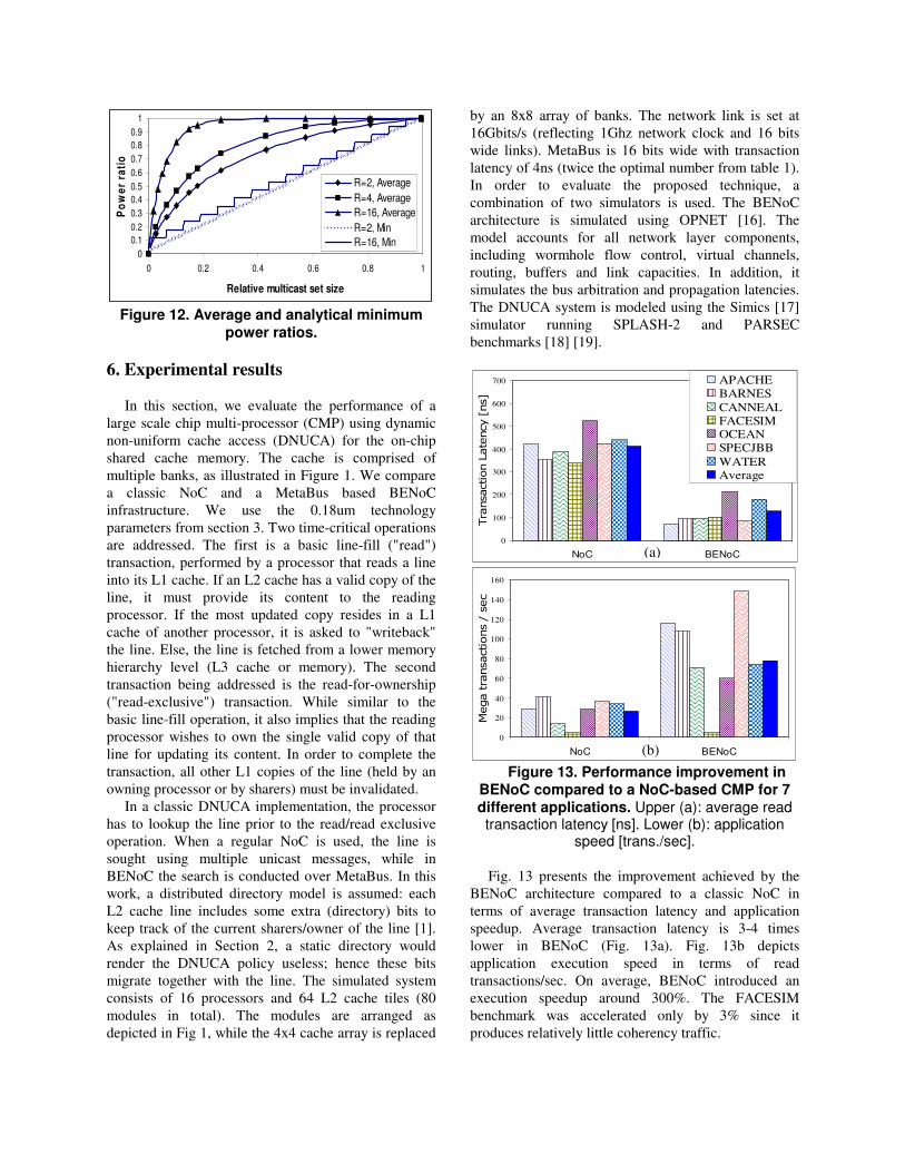
A simulation of power ratio vs. multicast set size for
256 modules trees with ranks of 2, 4 and 16 was
performed. For each rank and multicast set size we
have deduced the average PR of 10,000 different
random sets. In figure 12 we present the results
together with the minimum bound analytical results
from Eq. 18. As expected, the masking mechanism is
highly effective for unicast and small multicast sets.
Moreover, if modules are topologically arranged with
masking and multicast set awareness such as that
commonly used sets are concentrated topologically in
the tree, the masking mechanism stays effective even
for large multicast sets.
0
0.1
0.2
0.3
0.4
0.5
0.6
0.7
0.8
0.9
1
0 0.2 0.4 0.6 0.8 1
Relative multicast set size
Po
we
r ra
tio
R=2, Average
R=4, Average
R=16, Average
R=2, Min
R=16, Min
Figure 12. Average and analytical minimum
power ratios.
6. Experimental results
In this section, we evaluate the performance of a
large scale chip multi-processor (CMP) using dynamic
non-uniform cache access (DNUCA) for the on-chip
shared cache memory. The cache is comprised of
multiple banks, as illustrated in Figure 1. We compare
a classic NoC and a MetaBus based BENoC
infrastructure. We use the 0.18um technology
parameters from section 3. Two time-critical operations
are addressed. The first is a basic line-fill ("read")
transaction, performed by a processor that reads a line
into its L1 cache. If an L2 cache has a valid copy of the
line, it must provide its content to the reading
processor. If the most updated copy resides in a L1
cache of another processor, it is asked to "writeback"
the line. Else, the line is fetched from a lower memory
hierarchy level (L3 cache or memory). The second
transaction being addressed is the read-for-ownership
("read-exclusive") transaction. While similar to the
basic line-fill operation, it also implies that the reading
processor wishes to own the single valid copy of that
line for updating its content. In order to complete the
transaction, all other L1 copies of the line (held by an
owning processor or by sharers) must be invalidated.
In a classic DNUCA implementation, the processor
has to lookup the line prior to the read/read exclusive
operation. When a regular NoC is used, the line is
sought using multiple unicast messages, while in
BENoC the search is conducted over MetaBus. In this
work, a distributed directory model is assumed: each
L2 cache line includes some extra (directory) bits to
keep track of the current sharers/owner of the line [1].
As explained in Section 2, a static directory would
render the DNUCA policy useless; hence these bits
migrate together with the line. The simulated system
consists of 16 processors and 64 L2 cache tiles (80
modules in total). The modules are arranged as
depicted in Fig 1, while the 4x4 cache array is replaced
by an 8x8 array of banks. The network link is set at
16Gbits/s (reflecting 1Ghz network clock and 16 bits
wide links). MetaBus is 16 bits wide with transaction
latency of 4ns (twice the optimal number from table 1).
In order to evaluate the proposed technique, a
combination of two simulators is used. The BENoC
architecture is simulated using OPNET [16]. The
model accounts for all network layer components,
including wormhole flow control, virtual channels,
routing, buffers and link capacities. In addition, it
simulates the bus arbitration and propagation latencies.
The DNUCA system is modeled using the Simics [17]
simulator running SPLASH-2 and PARSEC
benchmarks [18] [19].
0
100
200
300
400
500
600
700
NoC BENoC
Transaction Latency [ns]
APACHEBARNES
CANNEALFACESIMOCEANSPECJBB
WATERAverage
0
20
40
60
80
100
120
140
160
NoC BENoC
Mega transactions / sec
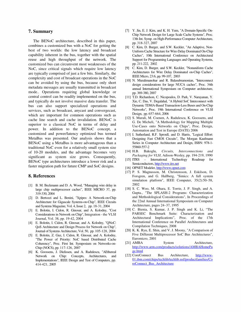
Figure 13. Performance improvement in
BENoC compared to a NoC-based CMP for 7 different applications. Upper (a): average read transaction latency [ns]. Lower (b): application
speed [trans./sec].
Fig. 13 presents the improvement achieved by the
BENoC architecture compared to a classic NoC in
terms of average transaction latency and application
speedup. Average transaction latency is 3-4 times
lower in BENoC (Fig. 13a). Fig. 13b depicts
application execution speed in terms of read
transactions/sec. On average, BENoC introduced an
execution speedup around 300%. The FACESIM
benchmark was accelerated only by 3% since it
produces relatively little coherency traffic.
(a)
(b)
7. Summary
The BENoC architecture, described in this paper,
combines a customized bus with a NoC for getting the
best of two worlds: the low latency and broadcast
capability inherent in the bus, together with the spatial
reuse and high throughput of the network. The
customized bus can circumvent most weaknesses of the
NoC, since critical signals which require low latency
are typically comprised of just a few bits. Similarly, the
complexity and cost of broadcast operations in the NoC
can be avoided by using the bus, because only short
metadata messages are usually transmitted in broadcast
mode.. Operations requiring global knowledge or
central control can be readily implemented on the bus,
and typically do not involve massive data transfer. The
bus can also support specialized operations and
services, such as broadcast, anycast and convergecast,
which are important for common operations such as
cache line search and cache invalidation. BENoC is
superior to a classical NoC in terms of delay and
power. In addition to the BENoC concept, a
customized and power/latency optimized bus termed
MetaBus was presented. Our analysis shows that a
BENoC using a MetaBus is more advantageous than a
traditional NoC even for a relatively small system size
of 10-20 modules, and the advantage becomes very
significant as system size grows. Consequently,
BENoC type architectures introduce a lower risk and a
faster migration path for future CMP and SoC designs.
8. References [1] B. M. Beckmann and D. A. Wood, “Managing wire delay in
large chip multiprocessor caches”, IEEE MICRO 37, pp.
319-330, 2004
[2] D. Bertozzi and L. Benini, "Xpipes: A Network-on-Chip
Architecture for Gigascale Systems-on-Chip", IEEE Circuits
and Systems Magazine, Vol. 4, Issue 2, pp. 18-31, 2004
[3] E. Bolotin, I. Cidon, R. Ginosar, and A. Kolodny, "Cost
Considerations in Network on Chip", Integration - the VLSI
Journal, Vol. 38, pp. 19-42, 2004
[4] E. Bolotin, I. Cidon, R. Ginosar, and A. Kolodny, "QNoC:
QoS Architecture and Design Process for Network on Chip",
Journal of Systems Architecture, Vol. 50, pp. 105-128, 2004
[5] E. Bolotin, Z. Guz, I. Cidon, R. Ginosar, and A. Kolodny,
"The Power of Priority: NoC based Distributed Cache
Coherency", Proc. First Int. Symposium on Networks-on-
Chip (NOCS), pp. 117-126, 2007
[6] K. Goossens, J. Dielissen, and A. Radulescu, "AEthereal
Network on Chip: Concepts, Architectures, and
Implementations", IEEE Design and Test of Computers, pp.
414-421, 2005
[7] Y. Jin, E. J. Kim, and K. H. Yum, "A Domain-Specific On-
Chip Network Design for Large Scale Cache Systems", Proc.
13th Int. Symp. on High-Performance Computer Architecture,
pp. 318-327, 2007
[8] C. Kim, D. Burger, and S.W. Keckler, "An Adaptive, Non-
Uniform Cache Structure for Wire-Delay Dominated On-Chip
Caches", 10th International Conference on Architectural
Support for Programming Languages and Operating Systems,
pp. 211-222, 2002
[9] C. Kim, D. Burger, and S.W. Keckler, "Nonuniform Cache
Architectures for Wire Delay Dominated on-Chip Caches",
IEEE Micro, 23:6, pp. 99-107, 2003
[10] N. Muralimanohar and R. Balasubramonian, "Interconnect
design considerations for large NUCA caches", Proc. 34th
annual International Symposium on Computer architecture,
pp. 369-380, 2007
[11] T.D. Richardson, C. Nicopoulos, D. Park, V. Narayanan, Y.
Xie, C. Das, V. Degalahal, "A Hybrid SoC Interconnect with
Dynamic TDMA-Based Transaction-Less Buses and On-Chip
Networks", Proc. 19th International Conference on VLSI
Design, pp. 657-664, 2006
[12] S. Murali, M. Coenen, A. Radulescu, K. Goossens, and
G. De Micheli, "A Methodology for Mapping Multiple
Use-Cases onto Networks on Chips", Proc. Design,
Automation and Test in Europe (DATE) 2006
[13] I. Sutherland, R.F. Sproull, and D. Harris, "Logical Effort:
Designing Fast CMOS Circuits", The Morgan Kaufmann
Series in Computer Architecture and Design, ISBN: 978-1-
55860-557-2
[14] H.B. Bakoglu, Circuits, Interconnections and
Packaging for VLSI, Adison-Wesley, pp. 194-219, 1990
[15] ITRS – International Technology Roadmap for
Semiconductors, http://www.itrs.net
[16] OPNET Modeler, http://www.opnet.com
[17] P. S. Magnusson, M. Christensson, J. Eskilson, D.
Forsgren, and G. Hallberg, "Simics: A full system
simulation platform", IEEE Computer, 35(2):50–58,
2002
[18] S. C. Woo, M. Ohara, E. Torrie, J. P. Singh, and A.
Gupta., "The SPLASH-2 Programs: Characterization
and Methodological Considerations", In Proceedings of
the 22nd Annual International Symposium on Computer
Architecture, pages 24–37, 1995
[19] C. Bienia, S. Kumar, J. P. Singh and K. Li, “The
PARSEC Benchmark Suite: Characterization and
Architectural Implications”, Proc. of the 17th
International Conference on Parallel Architectures and
Compilation Techniques, 2008
[20] K. K. Ryu, E. Shin, and V. J. Moony, "A Comparison of
Five Different Multiprocessor SoC Bus Architectures",
Euromicro, 2001
[21] AMBA System Architecture,
http://www.arm.com/products/solutions/AMBAHomePa
ge.html
[22] CoreConnect Bus Architecture, http://www-
01.ibm.com/chips/techlib/techlib.nsf/productfamilies/Co
reConnect_Bus_Architecture