1 The Passion of Alan Berg Transcript Tyler: Lost Highways ...
Upload
khangminh22Category
view
1download
0
November 7, 2013
Panel Boards - O&M Data
Specification Section: 26 24 16
Project #: 5737A
Escondido, CA 92029
For Review and Approval Stamping
Submittal No. 26 24 16 O&M
Bergelectric WO #: 14023
St Joseph's MAPC 3rd Floor TI
ENGINEER
Bridgers & Paxton Consulting Engineers
11209 North Tatum Blvd, Suite 160
Phoenix, Arizona 85028
ARCHITECT
ELECTRICAL SUBCONTRACTOR
Scottsdale, AZ 85259
Phoenix, AZ
Archsol
11445 East Villa Linda, Suite #2.325
GENERAL CONTRACTOR
Kitchell Contractors
1707 East Highland Ave, Suite 200
Phoenix, AZ 85016
Bergelectric Corporation
650 Opper Street
650 Opper Street, Escondido, CA 92029 - Tel (760) 746.1003 Fax (760) 741.0918 - License No. C10-85046

QUALITY ELECTRIC DISTRIBUTION 2929 SOUTH 16th STRET
PHOENIX, ARIZONA 85034
OPERATIONS & MAINTENANCE MANUAL
-GEAR-
PROJECT:
MUHAMMAD ALI PARKINSON CENTER & MOVEMENT DISORDER
CLINIC
ST. JOSEPH’S HOSPITAL & MEDICAL CENTER
240 WEST THOMAS ROAD PHOENIX, ARIZONA 85013
PREPARED FOR:
ELITE ELECTRIC SUPPLY

Page: 1
QED ELECTRICAL DISTRIBUTION Date: 10/18/2013 2929 SOUTH 16TH STREET Telephone: 602-256-1005 PHOENIX, AZ 85034 Fax: 602-258-2475 Email: [email protected] Speedi Version: V 10.10
Bill of Material
MUHAMMAD ALI PARKINSON CENTER AND MOVEMENT DISORDER CLINIC WIN Proposal #: 6N2-5724R2 Proposal/Quote Type: Revision #2 O&M _____________________________________________________________________________________________________________________________
Item# Qty Description _____________________________________________________________________________________________________________________________
1 1 Spectra Bolt-On Panel (101) DS-03NHB Single Section Panel Bottom Feed Surface Mnt 3P4W 480Y/277V 65 KAIC Height : 75.5" Width : 40" Depth : 14.25" 800A Main Lugs 1 1-LUG/PH 4-CABLE/LUG 2/0 -600 MCM 2 20A 3 Pole SELA3 Space 1 200A 3 Pole SFLA Space 1 225A 3 Pole SFLA 1 300A 3 Pole SGLA4 1 400A 3 Pole SGLA4 1 Copper Bus Heat Rated 1 Front Hinged To Box 1 Nameplates 1 47 Ckt bonded grd AEG47 1 APB4075D Box 1 APF7523EMDH Front 1 APNB2308FH2B Interior 2 1 Panelboard, Type AE (101) 03NHC Single Section Panel Top Feed Surface Mnt 42 Ckts 3P4W 480Y/277V 65 KAIC Height : 55.5" Width : 20" Depth : 5.75" 400A Main Lugs 1 1-LUG/PH 1-CABLE/LUG #4 -600 MCM OR 1-LUG/PH 2-CABLE/LUG 1/0 -250 MCM 1 60A 3 Pole TEYL 3 50A 3 Pole TEYL 3 40A 3 Pole TEYL 3 20A 3 Pole TEYL 12 20A 1 Pole TEYL Space 1 Copper Bus Heat Rated 1 Corbin Latch Bolt 15767 1 Front Hinged To Box 1 Nameplates 1 Ground main lug TGL20 4 Ground-Box bonded TGL2 1 AB55B Box 1 AF55SDLN Front 1 ASF3424MTX Interior AXS5B7

Page: 2
3 1 Panelboard, Type AQ (101) 03NLC Sec-1 Section 1 of 2 Bottom Feed Surface Mnt 42 Ckts 3P4W 208Y/120V 22 KAIC Height : 49.5" Width : 20" Depth : 5.75" 225A 3 Pole THQD Main 1 1-LUG/PH 1-CABLE/LUG #1 -300 MCM 42 20A 1 Pole THHQB 1 Feed Thru Lugs 1 Copper Bus Heat Rated 1 Front Hinged To Box 1 Nameplates 1 Same Box Size 2 Ground main lug TGL20 4 Ground-Box bonded TGL2 1 AB49B Box 1 AF49SDN Front 1 AQF3422CBX Interior AXT1B7 Sec-2 Section 2 of 2 Bottom Feed Surface Mnt 42 Ckts 3P4W 208Y/120V 22 KAIC Height : 49.5" Width : 20" Depth : 5.75" 225A Main Lugs 1 1-LUG/PH 1-CABLE/LUG #6 -350 MCM 42 20A 1 Pole THHQB 1 Copper Bus Heat Rated 1 Front Hinged To Box 1 Nameplates 1 Same Box Size 1 Ground main lug TGL20 4 Ground-Box bonded TGL2 1 AB49B Box 1 AF49SDN Front 1 AQF3422MBX Interior AXB7P1 4 1 Panelboard, Type AQ (101) 03NLD Single Section Panel Bottom Feed Surface Mnt 42 Ckts 3P4W 208Y/120V 22 KAIC Height : 64.5" Width : 20" Depth : 5.75" 300A 3 Pole SGHA4 Main 1 1-LUG/PH 2-CABLE/LUG 2/0 -500 MCM 38 20A 1 Pole THHQB 2 50A 2 Pole THHQB 1 Feed Thru Lugs 1 Copper Bus Heat Rated 1 Front Hinged To Box 1 Nameplates 2 Ground main lug TGL20 4 Ground-Box bonded TGL2 1 AB64B Box 1 AF64SDN Front 1 AQF3424JBX Interior AXT1S5B7

Spectra Panelboard Item 1 DS-03NHB
Panel DescriptionGE Type SBO Panelboard
Qty 1
800 Amp,480Y/277V
3P4W
65 KAIC SC Fully Rated
Copper Bus
Nema 1 Enclosure
Surface Mounted
Bottom Feed
Main DescriptionAmps: 800 Amp
Type: Main Lugs
Lugs: 1-lug/ph 4-cable/lug
2/0 -600 mcm
Branch Devices
Qty Amps/P Cat#
2 20A/3P Spaces
1 200A/3P Spaces
1 225A/3P SFLA36AT0250+
1 Rating Plg SRPF250A225
1 Lug Kit 3TCAL29
1 300A/3P SGLA36AT0400+
1 Rating Plg SRPG400A300
1 Lug Kit 1TCLK365
1 400A/3P SGLA36AT0400+
1 Rating Plg SRPG400A400
1 Lug Kit 1TCLK365
X Values
Pnl Main Branch Feature Filler
23 4 10 0 9
Options Included1 - Copper Bus Heat Rated
1 - Front Hinged To Box
1 - Nameplates
1 - 47 Ckt bonded grd AEG47
Panel Interior
Device Layout is Customer Specified
9 X FILLER
Ckt Type Amps/P Type Amps/P Ckt
1 SGLA4 300/3 SGLA4 400/3 2
- - - -
- - - -
- - - -
9 SFLA 225/3 SPACE 200/3 10
- - - -
- - - -
15 SPACE 20/3 SPACE 20/3 16
- - - -
- - - -
800A 3P
LUGS
* Drawing not to scale
Job Name: MUHAMMAD ALI PARKINSON CENTER
Prop No: 6N2-5724R2 GE Req#:
PO#:
Marks: DS-03NHB Dated: 10/18/2013
1A Interior APNB2308FH2B
1B Box APB4075D
1C Front APF7523EMDH
Dimensions 75.5"H x 40"W x 14.25"D

A Series Panelboard Item 2 03NHC
Panel DescriptionGE Type AS Panelboard
Qty 1
400 Amp,480Y/277V
3P4W
65 KAIC SC Fully Rated
Copper Bus
Nema 1 Enclosure
Surface Mounted
Top Feed
Main DescriptionAmps: 400 Amp
Type: Main Lugs
Lugs: 1-lug/ph 1-cable/lug
#4 -600 mcm
or
1-lug/ph 2-cable/lug
1/0 -250 mcm
Branch Devices
Qty Amps/P Cat#
1 60A/3P TEYL3060B
3 50A/3P TEYL3050B
3 40A/3P TEYL3040B
3 20A/3P TEYL3020B
12 20A/1P Spaces
Options Included1 - Copper Bus Heat Rated
1 - Corbin Latch Bolt 15767
1 - Front Hinged To Box
1 - Nameplates
1 - Ground main lug TGL20
4 - Ground-Box bonded TGL2
Panel Interior
Device Layout is Customer Specified
400A MAIN LUGS WITH NEUTRAL
Ckt Type Amps/P Type Amps/P Ckt
1 TEYL 60/3 TEYL 20/3 2
- - - -
- - - -
7 TEYL 40/3 TEYL 20/3 8
- - - -
- - - -
13 TEYL 20/3 TEYL 40/3 14
- - - -
- - - -
19 TEYL 50/3 TEYL 40/3 20
- - - -
- - - -
25 TEYL 50/3 TEYL 50/3 26
- - - -
- - - -
31 SPACE 20/1 SPACE 20/1 32
33 SPACE 20/1 SPACE 20/1 34
35 SPACE 20/1 SPACE 20/1 36
37 SPACE 20/1 SPACE 20/1 38
39 SPACE 20/1 SPACE 20/1 40
41 SPACE 20/1 SPACE 20/1 42
400A PANEL END FILLER
* Drawing not to scale
Job Name: MUHAMMAD ALI PARKINSON CENTER
Prop No: 6N2-5724R2 GE Req#:
PO#:
Marks: 03NHC Dated: 10/18/2013
2A Interior ASF3424MTX AXS5B7
2B Box AB55B
2C Front AF55SDLN
Dimensions 55.5"H x 20"W x 5.75"D

A Series Panelboard Item 3 03NLC
Panel DescriptionGE Type AQ Panelboard
Qty 1
225 Amp,208Y/120V
3P4W, Section 1 of 2
22 KAIC SC Fully Rated
Copper Bus
Nema 1 Enclosure
Surface Mounted
Bottom Feed
Main DescriptionAmps: 225 Amp
Poles: 3 Pole
Type: Main Breaker
Cat No.: THQD32225
Acc:
Lugs: 1-lug/ph 1-cable/lug
#1 -300 mcm
Branch Devices
Qty Amps/P Cat#
42 20A/1P THHQB1120
Options Included1 - Feed Thru Lugs
1 - Copper Bus Heat Rated
1 - Front Hinged To Box
1 - Nameplates
1 - Same Box Size
2 - Ground main lug TGL20
4 - Ground-Box bonded TGL2
Panel Interior
225A PANEL END FILLER
Ckt Type Amps/P Type Amps/P Ckt
1 THHQB 20/1 THHQB 20/1 2
3 THHQB 20/1 THHQB 20/1 4
5 THHQB 20/1 THHQB 20/1 6
7 THHQB 20/1 THHQB 20/1 8
9 THHQB 20/1 THHQB 20/1 10
11 THHQB 20/1 THHQB 20/1 12
13 THHQB 20/1 THHQB 20/1 14
15 THHQB 20/1 THHQB 20/1 16
17 THHQB 20/1 THHQB 20/1 18
19 THHQB 20/1 THHQB 20/1 20
21 THHQB 20/1 THHQB 20/1 22
23 THHQB 20/1 THHQB 20/1 24
25 THHQB 20/1 THHQB 20/1 26
27 THHQB 20/1 THHQB 20/1 28
29 THHQB 20/1 THHQB 20/1 30
31 THHQB 20/1 THHQB 20/1 32
33 THHQB 20/1 THHQB 20/1 34
35 THHQB 20/1 THHQB 20/1 36
37 THHQB 20/1 THHQB 20/1 38
39 THHQB 20/1 THHQB 20/1 40
41 THHQB 20/1 THHQB 20/1 42
225A 3P THQD
MAIN
225A FEED THRU LUGS WITH NEUTRAL
* Drawing not to scale
Job Name: MUHAMMAD ALI PARKINSON CENTER
Prop No: 6N2-5724R2 GE Req#:
PO#:
Marks: 03NLC Dated: 10/18/2013
3-1A Interior AQF3422CBX AXT1B7
3-1B Box AB49B
3-1C Front AF49SDN
Dimensions 49.5"H x 20"W x 5.75"D

A Series Panelboard Item 3 03NLC
Panel DescriptionGE Type AQ Panelboard
Qty 1
225 Amp,208Y/120V
3P4W, Section 2 of 2
22 KAIC SC Fully Rated
Copper Bus
Nema 1 Enclosure
Surface Mounted
Bottom Feed
Main DescriptionAmps: 225 Amp
Type: Main Lugs
Lugs: 1-lug/ph 1-cable/lug
#6 -350 mcm
Branch Devices
Qty Amps/P Cat#
42 20A/1P THHQB1120
Options Included4 - Ground-Box bonded TGL2
1 - Copper Bus Heat Rated
1 - Front Hinged To Box
1 - Nameplates
1 - Same Box Size
1 - Ground main lug TGL20
Panel Interior
225A PANEL END FILLER
Ckt Type Amps/P Type Amps/P Ckt
1 THHQB 20/1 THHQB 20/1 2
3 THHQB 20/1 THHQB 20/1 4
5 THHQB 20/1 THHQB 20/1 6
7 THHQB 20/1 THHQB 20/1 8
9 THHQB 20/1 THHQB 20/1 10
11 THHQB 20/1 THHQB 20/1 12
13 THHQB 20/1 THHQB 20/1 14
15 THHQB 20/1 THHQB 20/1 16
17 THHQB 20/1 THHQB 20/1 18
19 THHQB 20/1 THHQB 20/1 20
21 THHQB 20/1 THHQB 20/1 22
23 THHQB 20/1 THHQB 20/1 24
25 THHQB 20/1 THHQB 20/1 26
27 THHQB 20/1 THHQB 20/1 28
29 THHQB 20/1 THHQB 20/1 30
31 THHQB 20/1 THHQB 20/1 32
33 THHQB 20/1 THHQB 20/1 34
35 THHQB 20/1 THHQB 20/1 36
37 THHQB 20/1 THHQB 20/1 38
39 THHQB 20/1 THHQB 20/1 40
41 THHQB 20/1 THHQB 20/1 42
225A MAIN LUGS WITH NEUTRAL
* Drawing not to scale
Job Name: MUHAMMAD ALI PARKINSON CENTER
Prop No: 6N2-5724R2 GE Req#:
PO#:
Marks: 03NLC Dated: 10/18/2013
3-2A Interior AQF3422MBX AXB7P1
3-2B Box AB49B
3-2C Front AF49SDN
Dimensions 49.5"H x 20"W x 5.75"D

A Series Panelboard Item 4 03NLD
Panel DescriptionGE Type AQ Panelboard
Qty 1
400 Amp,208Y/120V
3P4W
22 KAIC SC Fully Rated
Copper Bus
Nema 1 Enclosure
Surface Mounted
Bottom Feed
Main DescriptionAmps: 300 Amp
Poles: 3 Pole
Type: Main Breaker
Cat No.: SGHA36AT0400+
Acc: SRPG400A300
Rating Plg
1TCLK365
Lug Kit
Lugs: 1-lug/ph 2-cable/lug
2/0 -500 mcm
Branch Devices
Qty Amps/P Cat#
38 20A/1P THHQB1120
2 50A/2P THHQB2150
Options Included1 - Feed Thru Lugs
1 - Copper Bus Heat Rated
1 - Front Hinged To Box
1 - Nameplates
2 - Ground main lug TGL20
4 - Ground-Box bonded TGL2
Panel Interior
Device Layout is Customer Specified
400A FEED THRU LUGS
Ckt Type Amps/P Type Amps/P Ckt
1 THHQB 50/2 THHQB 20/1 2
- - THHQB 20/1 4
5 THHQB 20/1 THHQB 20/1 6
7 THHQB 20/1 THHQB 20/1 8
9 THHQB 20/1 THHQB 20/1 10
11 THHQB 20/1 THHQB 20/1 12
13 THHQB 20/1 THHQB 20/1 14
15 THHQB 20/1 THHQB 20/1 16
17 THHQB 20/1 THHQB 20/1 18
19 THHQB 20/1 THHQB 20/1 20
21 THHQB 20/1 THHQB 20/1 22
23 THHQB 20/1 THHQB 20/1 24
25 THHQB 20/1 THHQB 20/1 26
27 THHQB 20/1 THHQB 20/1 28
29 THHQB 20/1 THHQB 20/1 30
31 THHQB 20/1 THHQB 20/1 32
33 THHQB 20/1 THHQB 20/1 34
35 THHQB 20/1 THHQB 20/1 36
37 THHQB 20/1 THHQB 20/1 38
39 THHQB 20/1 THHQB 50/2 40
41 THHQB 20/1 - -
400A VERTICAL MAIN BREAKER WITH NEUTRAL
* Drawing not to scale
Job Name: MUHAMMAD ALI PARKINSON CENTER
Prop No: 6N2-5724R2 GE Req#:
PO#:
Marks: 03NLD Dated: 10/18/2013
4A Interior AQF3424JBX AXT1S5B7
4B Box AB64B
4C Front AF64SDN
Dimensions 64.5"H x 20"W x 5.75"D

Spectra Series®
Power Panelboards
imagination at work
GE EnergyIndustrial Solutions

1
Spectra Series® Power PanelboardsFeatures
2 Types of Power Panelboards Available for Any Unique ApplicationSpectra Plug-In — Modular design utilizes plug-In modules
for circuit breakers and fusible switches.Spectra Bolt-On — Circuit Breakers attached through bolted
copper connections
Spectra Series Power Panel InteriorsGeneral Electric has designed plug-in and bolt-on style interiorsfor use in all Spectra Series® Power Panelboard applications.Spectra Plug-In interiors are designed for use with eitherfusible switches or molded case circuit breakers or both.Spectra Bolt-On interiors are designed for use with circuitbreakers only. Main or branch devices (fusible switch or circuitbreaker), as well as lugs only, can be installed in the factoryor at the construction site, providing for application flexibility.
Spectra Series Plug-In Interior
Double-insulated system consisting of bus support assemblies ofmolded, glass-filled polyester insulation and heat shrink tubingover high-strength steel bolts spaced on seven-inch centers prevent bus bars from distorting during short-circuit conditions.
Standard bus is tin-plated aluminum, density rated at 750 ampsper square inch. Optional ratings include 1000A psi silver platedcopper and reduced density 600A psi aluminum or 800A psi copper.
Maximum Voltage 600Vac250Vdc
Maximum Main Rating - Amperes– Lug Only 1200A– Fusible Switch 1200A– Breaker 1200ABranch Rating Amperes– Fusible Switch 30A - 1200A– Breakers 15A - 1200A
EnclosuresNEMA 1NEMA 3R/12NEMA 4X
Isolated bus support rails (2)
Protective devicemounting rails
Bolted copper connections featureanti-turn hardwarethat simplifies align-ment during circuitbreaker installation
Mounting rails (2)with means forpositioning,engaging andgrounding pres-sure-locked con-nections. (plug-in only).
Standard bus is aluminum, heat ratedper UL. Optional ratings include 750A psior 600A psi aluminum and heat ratedper UL, 1000A psi or 800A psi copper. Allvertical bus bars are silver plated.
Isolated bus support rails (2).
Double-insulated system consisting of bus supportassemblies of molded, glass-filled polyester insulationand insulating tubes over high-strength steel boltsspaced on 7" centers that prevent bus bars from distortingduring short-circuit conditions.

2
Spectra Series® Power PanelboardsFeatures
Flexibility for Multiple Applications
Spectra Bolt-On Power Panel:• Circuit Breakers attached through bolted copper connections• TVSS Unit• Main Lugs• Metering Modules
Spectra Plug-In Power Panel:• Circuit Breaker Modules• Fusible Switch Modules• Intermix of Circuit Breaker and Fusible Switch Modules• TVSS Unit• PCU Modules• Main Lug Modules• Metering Modules
Each interior is fully rated; therefore large amperage devices can be installed at either the top or bottom of the interior. The vertical design of the bus maximizes convective heat transfer. The bus bar insulator system provides short-circuit protection, 600-volt spacing (without having to add baffles). There is no need for any additional insulation.
GE Tranquell TVSS (Transient Voltage Surge Suppressor)provides outstanding protection from internally and externallygenerated transients.
Spectra Bolt-On Power PanelThe Spectra Bolt-On Power Panel provides economical solu-tions for your application needs. The design features mainlugs or main and branch circuit breakers bolted to the busbars. The factory-installed main lugs are bolted directly to thebus bars; circuit breakers are bolted with mounting straps.The Spectra Bolt-On power panelboard is rated for 100,000AIC. Fusible switches are not available in the bolt-on design.
Main lug assembly
Aluminum mechanical lugs are standard, copper and compression lugs are optional. The lugs are rated from 250to 1200 amps, and offer front accessible set screws.
Circuit breaker assembly
Circuit breakers are bolted to the bus bars with coppermounting straps utilizing anti-turn clips that simplify align-ment when field-installing breakers. The mounting straps aresized according to the breaker frame, not the trip amperage,and are rated for 100,000 AIC.

5
Spectra Series® Power PanelboardsFeatures
EnclosuresSpectra Series panelboards are available in 27, 31, 36, 40 and44 inch box widths, providing space-efficient enclosures. Thestandard NEMA 1 enclosure features a galvanized steel boxand a four piece ASA61 acrylic enamel powder coat front.
Device filler plates enable the different devices of differentwidths to align with the side trim. The side trim can be quicklyremoved to check wiring. Full width filler plates enabledevices of differing heights to be installed in the future. Allaccessories are available in kit form.
Snap-on filler plates make installation and maintenance quick and easy, providing a durable attachment with no loose hardware.
Mounting bracket for door-in-door front adjusting to panel with the quarter-turn latch.
Optional Door-in-Door Front
Optional surface mount door-in-door front available for allwidth enclosures. Regular door front, surface mount availablefor the 27" wide enclosure.
Removable trim allows quick access towiring, without exposing bus bar interiorto inadvertent contact.
Side trim (left, right)
Top end trim Bottom end trim
Type AFP filler plate
Type APP filler plate

6
Spectra Series® Power PanelboardsFeatures
Mounting bracket for door-in-door front adjusting to panel with the quarter-turn latch.
Enclosure DepthAll circuit breaker panel enclosures are 11.5" deep. Whendoor over devices is required, a 14.25" deep box is providedfor the 27", 31", and 40" wide enclosures and a 16.25" deepfor the 36" and 44" wide enclosures.
Enclosure Locks
Available door locks include an optional Corbin lock (far left), standard GE lock, optional T-handle and optional Yale lock.
Neutral and Equipment GroundingAssembliesNeutral bar assemblies are available in ratings from 250 ampsto 1200 amps. These neutrals have provisions for bonding andgrounding when required. The number of circuits has beenpre-engineered, depending on the amp rating. They can bemounted in either corner of the enclosure in the same endwhere the main device is installed. Each neutral is fully rated.
Equipment ground assembly
Isolated ground assembly
Isolated ground kit when required is field installed on either side
Power panel neutralsMechanical lugs are copper/aluminum as standard.Compression and oversized lugs are optional. Equipment-grounding modules are available either as bonded or isolated(refer to the National Electrical Code Article 250-74, Exception4). In special applications where non-linear loads are a concern,a 200% rated neutral can be installed.
600A maximum 1200A maximum
Series-Connected RatingsUL permits assigning a short circuit rating to a combination ofmolded case circuit breakers or fuses and molded case circuitbreakers connected in series that is higher than the lowestrated protective device of the combination. This is defined asseries connected ratings. The combination rating cannotexceed the rating of the protective device furthest upstream,although it will exceed the rating of the downstream protector.
The upstream protector can be a molded case breaker orfuse. Device combinations are not limited to those in the sameequipment. They can be in different equipments such as aswitchboard feeder or a panelboard main versus panelboard
Door OverDevices
Door OverDevices
Fusible or Circuit Breaker Panels 36", 44" Wide
Available Conduit Space
16.25"
11.5"
14.25"
11.5"
Circuit Breaker Panels 27", 31", 40" Wide

7
Spectra Series® Power PanelboardsElectrical Data
branches. Any distance between devices in different equip-ment is permitted. Total fault current magnitude must flowthrough both protectors. Thus, fault current contributionfrom motors, as well as power source fault current, mustflow through upstream and downstream protectors.
It appears NEMA’s position will allow motor full load currentsnot exceeding 1% of the downstream device interrupting ratingto be ignored.
Molded case circuit breakers may be applied as fully rated orseries rated. In a fully rated system, the short circuit ratingsof all protective devices are equal to, or exceed, the availableshort circuit current. If mounted in equipment, the bus shortcircuit withstand rating and equipment short circuit ratingmust equal or exceed the available short circuit current.
In a series connected system, the short circuit rating of theupstream protector is fully rated but the downstream protectoris not fully rated.
Selectivity between overcurrent devices is always desirablebut, in some cases, it difficult to achieve without over-sizingdevices or using Low Voltage Power Circuit Breakers inswitchgear. However, the National Electrical Code requirescomplete selectivity in some types of circuits. As of the 2008NEC, these include Elevator Control Circuits (article 620.62),Emergency Systems (Article 700.27), Legally RequiredStandby Systems (Article 701.18) and Critical OperationsPower Systems (Article 708.54).
Complete selectivity is usually interpreted as meaning selec-tivity for ground faults and all magnitude of phase faults upto maximum theoretical bolted fault current level. Somejurisdictions enforce the pertinent articles of the code only asfar as short time and long time selectivity, usually using the0.1-second rule. Other jurisdictions enforce the requirementfor complete selectivity. It is advisable that the localJurisdiction Having Authority (JHA) be consulted to understandthe interpretation of the pertinent code articles for the application being considered.
Full selectivity may be achieved in various ways. Traditionally, itis achieved by ensuring that the instantaneous characteristicof circuit breakers in series does not overlap up to availablefault current at the load side device. However, it is now possible to achieve instantaneous selectivity of molded casecircuit breakers even when their instantaneous time curvesoverlap. The selectivity available varies significantly by circuitbreaker model and size. To see available selectivity with GEcircuit breakers, please use GE publication DET-537. Beforeselecting circuit breakers for a panel or switchboard in circuitsor applications that may be regulated by the aforementionedcode articles, it is advisable that the interpretation enforcedby the local JHA be understood and that circuit breakerselection be undertaken with a full understanding on how toachieve the selectivity required.
Refer to GE publication DET-008A (in the latest edition) for complete series rating listings.
Interrupting RatingsPanelboards have integrated short-circuit ratings. Whenfully rated, the rating is that of the lowest-rated device in thepanelboard. When series-connected rated, the rating is thatof the main and branch-tested/UL Listed combination.
Short-Circuit Ratings - Fusible Switch UnitsThe short-circuit or interrupting rating of the fusible switch isthe lower of the fuse or the switch rating. Spectra Seriesswitches have a 200,000 amp short-circuit rating.
Table 1. Fuse Classification
Table 2. Maximum Horsepower� Fusible Switch
� Ratings are based on latest revision of the National Electrical Code Article 430.Horsepower ratings for switches with Standard Class H fuses are based on one-timefuses having minimum time-delay. When time-delay fuses are used, the horsepowerratings are maximum for the switches.
ULClass
AvailableAmpRating
MaximumShort-CircuitRating in Sym.RMS Amps
MaximumVoltage Application
H 30-600 10,000 250/600 One-time general purpose
J 30-600 200,000 600Fast-acting rejection sizing mains & feeders,current limiting
K 30-60050,000100,000200,000
250/600Dual element no rejectionmeans, motor startingcurrent limiting
L 800-1200 200,000 600
Rejection means availablein two forms• Fast-acting mains &feeders
• Time-delay motor starting current limiting
R 30-600 100,000200,000 250/600
Dual element rejectionmeans, motor startingcurrent limiting
T 100-600 200,000 250/600Fast-acting small physi-cal size mains & feeders,current limiting
Rating inAmps�
Volts, ac Volts, dc2- Pole 3-Pole 2-Pole 3-Pole
120 240 480 600 240 480 600 125 250With Standard Fuses30 1/2 1 1/2 3 3 3 5 7 1/2 2 560 1/2 3 5 10 7 1/2 15 15 5 10100 - 7 1/2 10 15 15 25 30 - 20200 - 15 25 30 25 50 60 - 40400 - - - - 50 100 125 - 50600 - - - - 75 150 200 - 50With “Time-delay” Fuses30 2 3 7 1/2 10 7 1/2 15 20 3 -60 3 10 20 25 15 30 50 - -100 - 15 30 40 30 60 75 - -200 - 15 50 50 60 125 150 - -400 - - - - 125 250 350 - -600 - - - - 200 400 500 - -

10
Spectra Series® Power PanelboardsElectrical Data
15-1200A Circuit BreakersElectric Trip Spectra® RMS Breakers
Spectra® RMS Circuit Breakers UL/CUL Ratings
SE 150
240 Vac 480 Vac 600 Vac H W D A B C E
2 480 —
3 600 14
2 480 —
3 600 18
2 480 —
3 600 25
2 480 —
3 600 25
2 480 —
3 600 22
2 480 —
3 600 25
2 480 —
3 600 25
SGH12,4 60-150 3 600 65 35 25
2
3
2 600
3 600
2 600
3 600
SGL14 3 600 100 65 65
SGP14 3 600 200 100 65
2 600 5 5
3 600
2 600
3 600
2 600
3 600
2 600
3 600
2
3
2
3
2
3
2
3 6 6
2
3
2
3
47.6 lb/18.56(217)
5.69(145)
1.38(35)
.62(16)
15.50(394)
8.25(210)
5.50(140)
Circuit Breaker
TypeAmpere Rating
No. Poles
Maximum
Vac
3.38(86)
200
SF-250 Current Limiting (UL File No. E-11592; CUL LR 40350)1
Solid-State with Interchangeable Trip Unit (Rating Plug)
UL Listed Interrupting Rating—kA Dimensions Inches (mm) Approx. Ship Wt./Std.
Pack
.72(18)
5.65 lb/1
SE150 Current Limiting (UL File No. E-11592; CUL LR 40350)1
SED2
SEH2
15-150
18
65
18
252.41(61)
2.47(63)
.69(18)
65
100
6.31(160)
4.12(105)
SEL
SEP
15-150
100
100
10.12(257)SFL
SFP
70-250
100
SFH2 70-250 65 35
.69(18)
1.19(30)
9.15 lb/1
SG600 Current Limiting (UL File No. E-11592; CUL LR 40350)1, 3
4.12(105)
3.81(97)
3.87(98)
3.87(98)65
200
SGD2
SGH42
240 65
65
125-400
— —
2535
25
60-150
SGL4 65
SGH62 250-600 65 35
SGP4
100
200
65
100 65
125-400
SGL6
SGP6
100 65
250-600
65
200 100 65
10.09(256)
5.50(140)
3.81(97)
4.45(113)
3.30(84)
.91(23)
1.18(30)
15.85 lb/1
SK1200 (UL File No. E-11592; CUL LR 40350)1, 3
SKH8
SKL8
SKP8
600
600
600
65
50 25
SKH12
SKL12
SKP12
300-800
600-1200
600
65
100
200
65
100
200
50
100
600
600
65
42
65
25
42
6Add 4.00 inches (101 mm) to upper end for SKP (100 kAIC-480V) lug cover.
2Not current-limiting circuit breaker.
4microEntelliGuard™ Trip Units only.
3 Includes microEntelliGuard™ Trip Units.
5Add 1.76 inches (45 mm) to each end with lugs and lug cover installed.
100
1UL listed as HACR (heating, air conditioning and refrigeration).
65

17
Spectra Series® Power PanelboardsPhysical Data
Main Lug TerminationsTable 15. Molded Case Circuit Breakers
Circuit Breaker Frame Terminal Lugs (Cu-Al)Current High No. Per Product Wire—Cu-Al (Unless otherwise noted)
Standard Hi-Break Tri-Break® Limiting Interrupting Poles Pole Number Per Lug Range
THQLTXQL,
— — — 1,2,3(15-30A) #14-4 Cu or #12-4 AlTHHQL
1 1(35-100A) #14-1/0 Cu or #12-1/0 AlTHQB
TXQB,— — — 1,2,3 Fixed to THHQB
Breaker Terminal (15-25A) #14-#12 Cu or #12-#10 AlTEY — — — — 1,2,3 1 1 (30-60A) #10-#6 Cu or #8-#4 Al
(70-100A) #4-#1 Cu or #2-1/0 AlTEB — — — — 1,2,3 TCAL14 (15-30A, TCAL14)–#14-8TED THED1 — — — 1
1TCAL12
1(30-60A, TCAL12)–#14-3 Cu, #12-1 Al
TED4 — — — — 2-3 TCAL12A (70-90A, TCAL12A)–#6-2/0 Cu, #4-2/0 AlTED6 THED — — — 2-3 TCAL15 (100-150A, TCAL15)–#3-3/0
FBV FBN FCAL12 (15-20A) #14-#12 Cu or #10-#12 Al
— — —FBH FBL
— 1,2,3 1 FCAL13 1 (35-60A) #10-#6 Cu or #8-#4 AlFCAL14 (70-100A) #4-#1 Cu or #2-1/0 Al
FCS FCV FCNFCALK12 (15-20A) #14-#12 Cu or #10-#12 Al
— — —FCH FCL
— 2,3 1 FCALK13 1 (35-60A) #10-#6 Cu or #8-#4 AlFCALK14 (70-100A) #4-#1 Cu or #2-1/0 Al
SEDA SEHA — SELA SEPA — 2-3 1 TCAL18 1 #12-3/0 Cu, #12-3/0 Al
— — —FES1T FEV1T
— 2-3 1 FCALK15 1 #12-3/0 Cu, #14-1/0 AlFEN1T FEH1T FEL1T
— — —FES1E FEV1E
— 2-3 1 FCALK15 1 #12-3/0 Cu, #14-1/0 AlFEN1E FEH1E FEL1ETQD THQD — — — 2-3 1 TCAL25 1 #1-300kcmilSFHA — — SFLA SFPA — 2-3 1 TCAL29 1 #8-350kcmil
TFJ, TFK THFK — — — 2-3 1 TCAL24, 26 1 #4-300kcmil
— — —FES2T FEV2T
— 2-3 1 FCALK16 1 #8-250kcmil Cu, #8-250kcmilFEN2T FEH2T FEL2T
— — —FES2E FEV2E
— 2-3 1 FCALK16 1 #8-250kcmil Cu, #8-250kcmilFEN2E FEH2E FEL2ESGDA
— —SGL
— 2 1 TCLK2652 —2(2/0-400kcmil Cu) or
SGHA SGP 2(2/0-500kcmil Al) or #6-600kcmilSGDA
— —SGL
— 3 1 TCLK3652 —2(2/0-400kcmil Cu) or
SGHA SGP 2(2/0-500kcmil Al) or #6-600kcmilFGV2 Top hole #8-400kcmil Cu or
— — — FGN2 FGH2 — 2-3 1 FCALK318H — #6-500kcmil AlFGL2 FGP2 Bottom hole #2/0-600kcmil Cu & Al
FGV4 Top hole #8-400kcmil Cu or— — — FGN4 FGH4 — 2-3 1 FCALK318H — #6-500kcmil Al
FGL4 FGP4 Bottom hole #2/0-600kcmil Cu & AlFGV6 Top hole #8-400kcmil Cu or
— — — FGN6 FGH6 — 2-3 1 FCALK318H — #6-500kcmil AlFGL6 FGP6 Bottom hole #2/0-600kcmil Cu & Al
TJJ, TJK4 THJK4 TB4 — — 2-3 1 TCAL43 1 #6-600kcmil or 2-(2/0-250kcmil)TJD — — — — 2-3 1 TCAL43 1 #6-600kcmil or 2-(2/0-250kcmil)
TJK6 THJK6, THJ4V — — — 2-3 1TCAL43 1 #6-600kcmil or 2-(2/0-250kcmil)TCAL63 2 250-350kcmil, Cu, or 350-500kcmil, Al
— — TB6 — — 3 1 TCAL61 2 2/0-500kcmil
SKHA8 SKLA8TCAL41 1 #4-600kcmil or 2-(1/0-250kcmil)
TKM84THKM8 — —
SKPA82-3 1 TCAL61 2 2/0-500kcmil
TCAL81 3 3/0-500kcmil— — — — Load End — 1 TCAL91 3 3/0-500kcmil— — TB8 — — 3 1 TCAL81 3 3/0-500kcmil
SKHA12,THKM12 — —
SKLA12,2-3 1
TCAL81 3 3/0-500kcmilTKM124 SKPA12 TCAL121 4 250-350kcmil Cu or 350-5000kcmil Al
— — — — Load End 2-3 1 TCAL131 4 250-350kcmil Cu or 350-500kcmil AlTCAL12 (15-60A, TCAL12)#14-#3 Cu or #12-#1 Al
— — TB1 THLC1 — 3 1 TCAL12A 1 (70-100A, TCAL12A)#6-2/0 Cu or #4-2/0 AlTCAL15 (100-150A, TCAL15)#3-3/0 Cu or #1-3/0 Al
— — — THLC2 — 3 1 TCAL27 1 (125-225A, TCAL27)#4-300kcmil— — — THLC4 TLB44 3 1 TCLK433 — 3/0-500kcmil or 2-(3/0-250kcmil)
1One-pole THED frame available only in 15-30 amp trip. 3Three-pole lug assembly suitable for line or load end.2Lug kit—includes line or load end cover. 4For replacement use only.
18
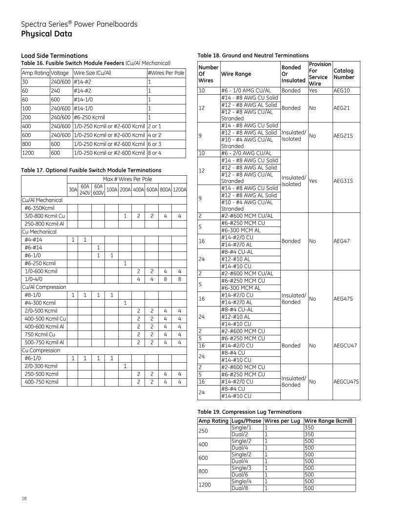
Spectra Series® Power PanelboardsPhysical Data
Load Side TerminationsTable 16. Fusible Switch Module Feeders (Cu/Al Mechanical)
Table 17. Optional Fusible Switch Module Terminations
Table 18. Ground and Neutral Terminations
Table 19. Compression Lug Terminations
Max # Wires Per Pole
30A 60A240V
60A600V 100A 200A 400A 600A 800A 1200A
Cu/Al Mechanical#6-350Kcmil3/0-800 Kcmil Cu 1 2 2 4 4250-800 Kcmil AlCu Mechanical#4-#14 1 1#6-#14 1#6-1/0 1 1#6-250 Kcmil 11/0-600 Kcmil 2 2 4 41/0-4/0 4 4 8 8Cu/Al Compression#8-1/0 1 1 1 1#4-300 Kcmil 12/0-500 Kcmil 2 2 4 4400-500 Kcmil Cu 2 2 4 4400-600 Kcmil Al 2 2 4 4750 Kcmil Cu 2 2 4 4500-750 Kcmil Al 2 2 4 4Cu Compression#6-1/0 1 1 1 12/0-300 Kcmil 1250-500 Kcmil 2 2 4 4400-750 Kcmil 2 2 4 4
Amp Rating Voltage Wire Size (Cu/Al) #Wires Per Pole
30 240/600 #14-#2 1
60 240 #14-#2 1
60 600 #14-1/0 1
100 240/600 #14-1/0 1
200 240/600 #6-250 Kcmil 1
400 240/600 1/0-250 Kcmil or #2-600 Kcmil 2 or 1
600 240/600 1/0-250 Kcmil or #2-600 Kcmil 4 or 2
800 600 1/0-250 Kcmil or #2-600 Kcmil 6 or 3
1200 600 1/0-250 Kcmil or #2-600 Kcmil 8 or 4
NumberOfWires
Wire RangeBondedOrInsulated
ProvisionForServiceWire
CatalogNumber
10 #6 - 1/0 AMG CU/AL Bonded Yes AEG10
12
#14 - #8 AWG CU Solid
Bonded No AEG21#12 - #8 AWG AL Solid#12 - #8 AWG CU/ALStranded
9
#14 - #8 AWG CU SolidInsulated/Isolated No AEG21S#12 - #8 AWG AL Solid
#10 - #4 AWG CU/ALStranded
10 #6 - 2/0 AWG CU/AL
Insulated/Isolated Yes AEG31S
12
#14 - #8 AWG CU Solid#12 - #8 AWG AL Solid#12 - #8 AWG CU/ALStranded
9
#14 - #8 AWG CU Solid#12 - #8 AWG AL Solid#10 - #4 AWG CU/ALStranded
2 #2-#600 MCM CU/AL
Bonded No AEG47
5#6-#250 MCM CU#6-300 MCM AL
16#14-#2/0 CU#14-#2/0 AL
24#8-#4 CU-AL#12-#10 AL#14-#10 CU
2 #2-#600 MCM CU/AL
Insulated/Bonded No AEG47S
5#6-#250 MCM CU#6-300 MCM AL
16#14-#2/0 CU#14-#2/0 AL
24#8-#4 CU-AL#12-#10 AL#14-#10 CU
2 #2-#600 MCM CU
Bonded No AEGCU475 #6-#250 MCM CU16 #14-#2/0 CU
24#8-#4 CU#14-#10 CU
2 #2-#600 MCM CU
Insulated/Bonded No AEGCU47S
5 #6-#250 MCM CU16 #14-#2/0 CU
24#8-#4 CU#14-#10 CU
Amp Rating Lugs/Phase Wires per Lug Wire Range (kcmil)
250 Single/1 1 350Dual/2 1 350
400 Single/2 1 500Dual/4 1 500
600 Single/2 1 500Dual/4 1 500
800 Single/3 1 500Dual/6 1 500
1200 Single/4 1 500Dual/8 1 500

19
Spectra Series® Power PanelboardsPhysical Data
Spectra Bolt-On Mounting Hardware andSpare PartsTable 20. Spectra Bolt-On Panel Device Mounting Hardware
� Mounting kit with filler plate includes hardware, straps, brackets and filler plate.� Filler plate kit includes filler plate and associated hardware only.Note: X=1.375"
Table 21. Spectra Bolt-On Hardware Kits (Hardware only; no brackets or straps)
Table 22. Full Filler Plates (To cover unused spaces)
Enclosure DimensionsEstimating Enclosure DimensionsSpectra Series panelboard enclosures are provided in fourbox heights and five box widths. Enclosure sizes are determined by ampere rating and installed device sizes.
A. Determine applicable main x-height and minimum enclosure width from tables 12.1 - 12.5.Enter: X-Height __________Minimum Width __________
B. Determine total branch x-height and minimum enclosurewidth (switches and breakers may be mixed) from tables13.1, 13.2 or 14.1.Enter: X-Height __________Minimum Width __________
C. Total up x-heights and review table 20.1 to determine boxheight. If total X-height exceeds tabulated values, multiplepanel sections are required.Enter: Total X-Height __________Box Height __________Box Width __________(Highest number from steps A or B)
D. Multiple Section Panels: Include main lug x-height foreach additional section. For 800 and 1200A ratings review note � below table 20.1. When first sectionincludes a main device, feed thru lugs are required — add MLO x-height to first section.
E. See page 21 for box depth.
F. NEMA 3R/12 Enclosure size can be developed by followingsteps A thru C and using Table 21.1 to determine NEMA3R/12 size.
“X” Heightof Space
Catalog Number
1X APP1S APP1 APP1W2X APP2S APP2 APP2W3X APP3S APP3 APP3W4X APP4S APP4 APP4W5X APP5S APP5 APP5W6X APP6S APP6 APP6W
27"/31" Wide Box 36"/40" Wide Box 44" Wide Box
Circuit Breaker Type Catalog NumberFB AHKBFB1FC AHKBFD1FE AHKBFE1FG AHKBFG1S7H AHKBS71SE/THLC1 AHKBE1SF AHKBF1SG AHKBG1THQD AHKBQ1THLC2,4 AHKBLB1
Type X-Height
MinimumBox Width
Mounting KitWith Filler Plate�
FillerPlate�
Twin Mounted DevicesFB (3-pole) 2X 27 AMCB4FBFP AFP3FBDFB (2-pole) 3X 27 AMCB6FBFP AFP2FBDFC (3-pole) 3X 27 AMCB4FDBFP AFP3FDDFC (2-pole) 3X 27 AMCB6FDBFP AFP3FDDFE (3-pole) 3X 31 AMCB4FEBFP AFP3FEDFE (2-pole) 3X 31 AMCB6FEBFP AFP3FEDFG (3-pole) 4X 40 AMCB4FGBFP AFP4FGDFG (2-pole) 4X 40 AMCB6FGBFP AFP4FGDTQD, THQD (3-pole) 3X 27 AMCB6QDFP AFP3QDDTQD, THQD (2-pole) 2X 27 AMCB4QDFP AFP2QDDTEB, TED, THED, SED,SEH, SEL, SEP (3-pole) 3X 27 AMCB6EBFP AFP3SED
THED, SED, SEH, SEL,SEP (2-pole) 3X 27 AMCB4SEFP AFP3SED
TEB, TED (2-pole) 2X 27 AMCB4EBFP AFP2TEDSFH. SFL, SFP (3-pole) 3X 31 AMCB6FJFP AFP3SFDSFH. SFL, SFP (2-pole) 3X 31 AMCB4FJFP AFP3SFDTFJ, TFK, THFK (3-pole) 3X 36 AMCB6FJFPTF AFP3TFDTFJ, TFK, THFK (2-pole) 2X 36 AMCB4FJFPTF AFP3TFDSGH, SGL, SGP (3-pole) 4X 40 AMCB6GBFP AFP4SGDSGH, SGL, SGP (2-pole) 4X 40 AMCB4GBFP AFP4SGDTEY (3-pole) 3X 27 AMCB6EYFP AFP3EYDTEY (2-pole) 3X 27 AMCB4EYFP AFP3EYDSingle Mounted DevicesFG (3-pole) 4X 27 AMCB3FGMFP AFP4FGSFG (2-pole) 4X 27 AMCB2FGMFP AFP4FGSSFH, SFL, SFP (3-pole) 3X 27 AMCB3FJFP AFP3SFSSFH, SFL, SFP (2-pole) 3X 27 AMCB2FJFP AFP3SFSTFJ 3X 27 AMCB3FJFPTF AFP3TFSTFJ 3X 27 AMCB2FJFPTF AFP3TFSSGH, SGL, SGP (3-pole) 4X 27 AMCB3GMFP AFP4SGSSGH, SGL, SGP (2-pole) 4X 27 AMCB2GMFP AFP4SGSSKH, SKL, SKP, TKM,THKM (3-pole) 6X 40 AMCB3KMFP AFP6SKS
SKP (3-pole) 6X 44 AMCB3KMFP AFP6SKSSKH, SKL, SKP, TKM,THKM (2-pole) 6X 40 AMCB2KMFP AFP6SKS
SKP (2-pole) 6X 44 AMCB2KMFP AFP6SKS

20
Spectra Series® Power PanelboardsPhysical Data
Spectra Series Power PanelsNEMA 1 Enclosure DimensionsEnclosure boxes are constructed of code gauge galvanizedsheet steel and meet UL 50. 27" thru 40" wide enclosure boxsteel is 0.069" thick, and 44" wide box steel is 0.108" thick.
All circuit breaker panel enclosures are 11.5" deep. Whendoor over devices is required, a 14.25" deep box is providedfor the 27", 31", and 40" wide enclosures and a 16.25" deepfor the 36" and 44" wide enclosures.
Table 23. Spectra Series Enclosures (Note: X value is 1.375")
� This dimension may change if dual main or feed through and neutral are provided.� This enclosure is available for use with a single main and single neutral only.� This enclosure is not available for use with 200% neutrals.
Main AmpRating
Interior Height Gutter Inches Enclosure DimensionsX-Height Inches A B Height Inches 27" Wide 31" Wide 36" Wide 40" Wide 44" Wide
250
18X 24.75 19.94 19.94 64.63 APB2765 APB3165 APB3665 - -23X 31.63 19.94 13.13 64.63 APB2765 APB3165 APB3665 - -28X 38.50 19.94 6.25 64.63 APB2765 APB3165 APB3665 - -38X 52.25 22.75 14.25 89.25 APB2789 APB3189 APB3689 - -48X 66.00 19.94 10.25 96.13 - APB3196 APB3696 - -
400
18X 24.75 19.94 19.94 64.63 APB2765 APB3165 APB3665 APB4065 APB446523X 31.63 19.94 13.13 64.63 APB2765 APB3165 APB3665 APB4065 APB446528X 38.50 22.75 14.25 75.50 APB2775 APB3175 APB3675 APB4075 APB447533X 45.38 22.75 21.25 89.25 APB2789 APB3189 APB3689 APB4089 APB448938X 52.25 22.75 14.25 89.25 APB2789 APB3189 APB3689 APB4089 APB448948X 66.00 19.94 10.25 96.13 - APB3196 APB3696 APB4096 APB4496
600
23X 31.63 19.94� 13.13� 64.63� APB2765 APB3165 APB3665 APB4065 APB446528X 38.50 22.75 14.25 75.50 APB2775 APB3175 APB3675 APB4075 APB447533X 45.38 22.75 21.25 89.25 APB2789 APB3189 APB3689 APB4089 APB448938X 52.25 22.75 14.25 89.25 APB2789 APB3189 APB3689 APB4089 APB448943X 59.13 22.75 14.25 96.13 - APB3196 APB3696 APB4096 APB449648X� 66.00 19.94 10.25 96.13 - APB3196 APB3696 APB4096 APB4496
800
23X 31.63 22.75� 21.25� 75.50 - APB3175 APB3675 APB4075 APB447528X� 38.50 22.75 14.25 75.50 - APB3175 APB3675 APB4075 APB447533X� 45.38 22.75 21.25 89.25 - APB3189 APB3689 APB4089 APB448938X 52.25 22.75� 14.25 89.25� - APB3189 APB3689 APB4089 APB448943X� 59.13 22.75 14.25 96.13 - APB3196 APB3696 APB4096 APB4496
1200
23X 31.63 22.75� 21.25� 75.50 - APB3175 APB3675 APB4075 APB447528X� 38.50 22.75 14.25 75.50 - APB3175 APB3675 APB4075 APB447533X� 45.38 22.75 21.25 89.25 - APB3189 APB3689 APB4089 APB448938X 52.25 22.75� 14.25 89.25� - APB3189 APB3689 APB4089 APB448943X� 59.13 22.75 14.25 96.13 - APB3196 APB3696 APB4096 APB4496

21
Spectra Series® Power PanelboardsPhysical Data
NEMA 3R/12 and NEMA 4X Enclosure Dimensions
NEMA 3R/12 enclosures are UL 50 listed and constructed of galvanized steel and paintedANSI-61 gray. NEMA 4X enclosures are available in AISI-316 stainless steel grade.
Table 24. NEMA 3R/12 and NEMA 4X Enclosure Dimensions (inches)
Table 25. Conduit Hubs (require field cut openings)Select the necessary hub from chart below and order from your GE distributor.
Nominal ConduitDiameter in Inches
Zinc Hub GECatalog Number
Chrome Plated Zinc HubGE Catalog Number
1/2 343L647G3 343L647G173/4 343L647G4 343L647G181 343L647G5 343L647G1911/4 343L647G6 343L647G2011/2 343L647G7 343L647G212 343L647G8 343L647G2221/2 343L647G9 343L647G233 343L647G10 343L647G2431/2 343L647G11 343L647G254 343L647G12 343L647G26
Exterior BoxA B C
Width Height27.19 64.82 69.98 22.44 16.3827.19 75.70 80.88 22.44 16.3827.19 89.45 94.61 22.44 16.3831.19 64.82 69.98 22.44 16.3831.19 75.70 80.88 22.44 16.3831.19 89.45 94.61 22.44 16.3836.19 64.82 69.98 21.44 18.3836.19 75.70 80.88 21.44 18.3836.19 89.45 94.61 21.44 18.3840.19 64.82 69.98 22.44 16.3840.19 75.70 80.88 22.44 16.3844.19 64.82 69.98 22.44 18.3844.19 75.70 80.88 22.44 18.38
Key lockable 3-point T-handle.
Side View Rear View
A
BC
1.75"(3R only)
0.875"
22
Spectra Series® Power PanelboardsApplication Data
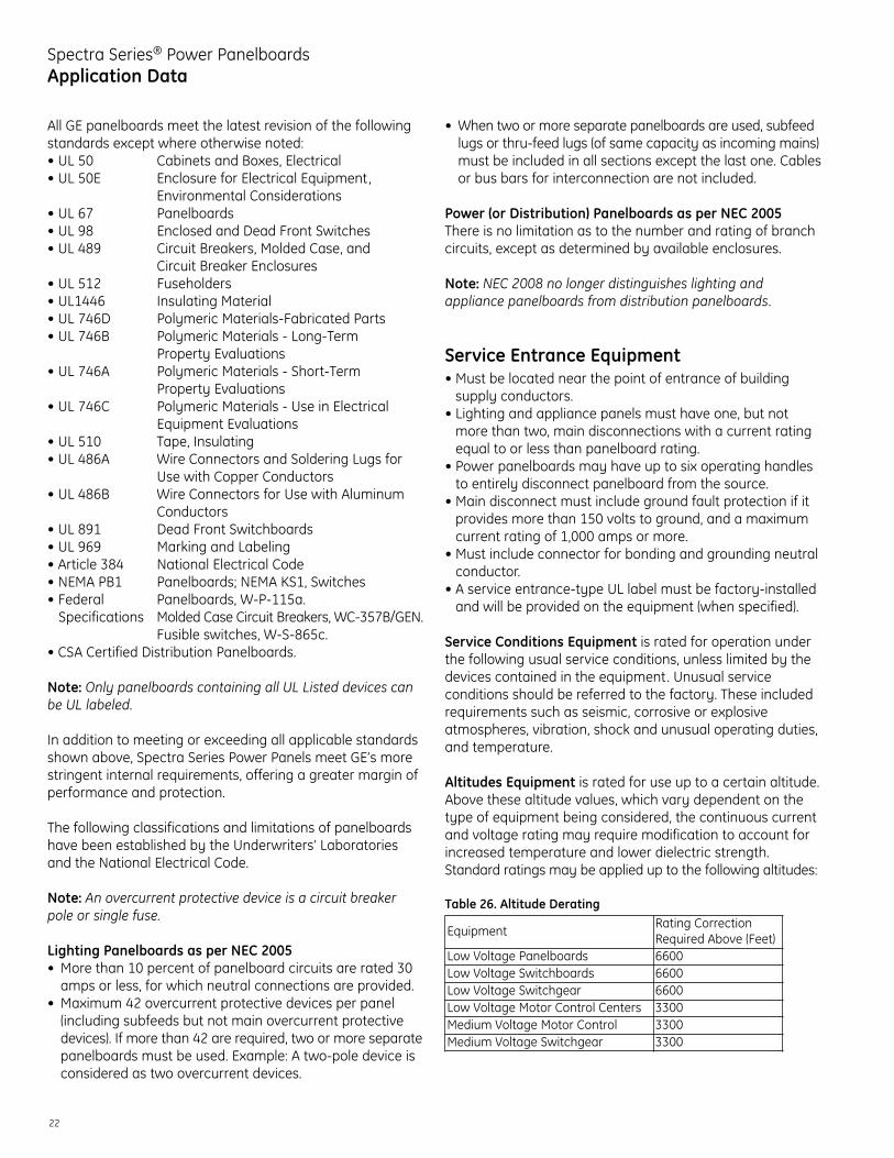
All GE panelboards meet the latest revision of the followingstandards except where otherwise noted:• UL 50 Cabinets and Boxes, Electrical• UL 50E Enclosure for Electrical Equipment,
Environmental Considerations• UL 67 Panelboards• UL 98 Enclosed and Dead Front Switches• UL 489 Circuit Breakers, Molded Case, and
Circuit Breaker Enclosures• UL 512 Fuseholders• UL1446 Insulating Material• UL 746D Polymeric Materials-Fabricated Parts• UL 746B Polymeric Materials - Long-Term
Property Evaluations• UL 746A Polymeric Materials - Short-Term
Property Evaluations• UL 746C Polymeric Materials - Use in Electrical
Equipment Evaluations• UL 510 Tape, Insulating• UL 486A Wire Connectors and Soldering Lugs for
Use with Copper Conductors• UL 486B Wire Connectors for Use with Aluminum
Conductors• UL 891 Dead Front Switchboards• UL 969 Marking and Labeling• Article 384 National Electrical Code• NEMA PB1 Panelboards; NEMA KS1, Switches• Federal Panelboards, W-P-115a. Specifications Molded Case Circuit Breakers, WC-357B/GEN.
Fusible switches, W-S-865c.• CSA Certified Distribution Panelboards.
Note: Only panelboards containing all UL Listed devices canbe UL labeled.
In addition to meeting or exceeding all applicable standardsshown above, Spectra Series Power Panels meet GE’s morestringent internal requirements, offering a greater margin ofperformance and protection.
The following classifications and limitations of panelboardshave been established by the Underwriters’ Laboratoriesand the National Electrical Code.
Note: An overcurrent protective device is a circuit breaker pole or single fuse.
Lighting Panelboards as per NEC 2005• More than 10 percent of panelboard circuits are rated 30amps or less, for which neutral connections are provided.
• Maximum 42 overcurrent protective devices per panel(including subfeeds but not main overcurrent protectivedevices). If more than 42 are required, two or more separatepanelboards must be used. Example: A two-pole device isconsidered as two overcurrent devices.
• When two or more separate panelboards are used, subfeedlugs or thru-feed lugs (of same capacity as incoming mains)must be included in all sections except the last one. Cablesor bus bars for interconnection are not included.
Power (or Distribution) Panelboards as per NEC 2005There is no limitation as to the number and rating of branchcircuits, except as determined by available enclosures.
Note: NEC 2008 no longer distinguishes lighting and appliance panelboards from distribution panelboards.
Service Entrance Equipment• Must be located near the point of entrance of building supply conductors.
• Lighting and appliance panels must have one, but notmore than two, main disconnections with a current ratingequal to or less than panelboard rating.
• Power panelboards may have up to six operating handlesto entirely disconnect panelboard from the source.
• Main disconnect must include ground fault protection if itprovides more than 150 volts to ground, and a maximumcurrent rating of 1,000 amps or more.
• Must include connector for bonding and grounding neutralconductor.
• A service entrance-type UL label must be factory-installedand will be provided on the equipment (when specified).
Service Conditions Equipment is rated for operation underthe following usual service conditions, unless limited by thedevices contained in the equipment. Unusual service conditions should be referred to the factory. These includedrequirements such as seismic, corrosive or explosive atmospheres, vibration, shock and unusual operating duties,and temperature.
Altitudes Equipment is rated for use up to a certain altitude.Above these altitude values, which vary dependent on thetype of equipment being considered, the continuous currentand voltage rating may require modification to account forincreased temperature and lower dielectric strength.Standard ratings may be applied up to the following altitudes:
Table 26. Altitude Derating
EquipmentRating CorrectionRequired Above (Feet)
Low Voltage Panelboards 6600Low Voltage Switchboards 6600Low Voltage Switchgear 6600Low Voltage Motor Control Centers 3300Medium Voltage Motor Control 3300Medium Voltage Switchgear 3300

23
Spectra Series® Power PanelboardsApplication Data
For derating correction factors to be applied when the alti-tude exceeds the above, refer to the equipment applicationbulletins or factory.
Ambient Temperature Equipment is rated for use in a givenambient, and if exceeded, the continuous current ratingrequires derating. Rating correction is required if applied inan ambient exceeding the following:
Table 27. Ambient Derating
For derating correction factors to be applied when the ambi-ent exceeds the above, refer to the equipment applicationbulletins or factory.
Current. The continuous current carried by a protectivedevice should not exceed 80% of the device rating unlessthe equipment or assembly, including the protective device,is listed for continuous operation at 100% of its rating. Acontinuous load current is one that continues for threehours or more. A noncontinuous load current may be 100%of the device rating.
Low-voltage fusible switches are standard-rated 80% excepthigh pressure contact and bolted pressure switches, whichare 100% rated. Molded case circuit breakers equipped withthermal magnetic trips are standard-rated (80%). Whenequipped with electronic trips, they can be standard (80%)or 100% rated.
When mounted in equipment, MCCB and fusible switches ingroup-mounted configuration are all standard (80%) rated. Inindividual mounted configuration, MCCB with electronic tripcan be standard (80%) or 100% rated. Insulated case circuitbreakers are standard (80%) or 100% rated. Low-voltagepower circuit breakers, type AKR, medium-voltage fuses, andmedium-voltage breaker PowerVac are all 100% rated. Low-voltage protective devices are fast operating and their short-circuit rating is based on the maximum current during thefirst half cycle of fault current flow. The total fault current atinitiation of fault consists of two components: the ac and dccomponents. The ac component is defined as the symmetricalrms current, and ac plus dc, the asymmetrical rms current.The magnitude and rate of decay of the dc component is afunction of the reactance to the resistance (X/R) ratio. Low-voltage protective devices are rated on the basis of
symmetrical rms amps, but tested at known X/R ratios toassure capability of interrupting the total fault currentasymmetrical fault. The X/R ratios at which they are testedare as follows:
Table 28
Thus, the low-voltage protective device interrupting ratingsymmetrical rms must be equal to, or greater than, the circuitsymmetrical rms fault current and test X/R equal to, orgreater than, circuit X/R at point of application. If the circuitasymmetrical current should be greater than the protectivedevice will withstand, then the protective devices interruptingrating must be derated. Derating factors are identified in theapplicable application bulletins and standards.
Medium-and high-voltage fuses are rated in terms of sym-metrical current, but can withstand the total asymmetricalcurrent provided the X/R ratio does not exceed 15. If the circuitwhere applied exceeds an X/R of 15, then it is necessary toderate the symmetrical current rating in accordance withthe applicable standard. Proper application of medium- andhigh-voltage breakers requires that the circuit-short-circuitduties during the first cycle (momentary), and at contactparting time (interrupting), be compared with the circuitbreaker’s short-circuit capability to close and latch duringthe first cycle, and to interrupt at some time later. Refer toGET 3550 to determine methods of calculating short-circuitcurrents for proper application.
Low Voltage Protective Device X/RPower Circuit Breaker (AKR) 6.6Insulated Case Circuit Breaker (ICCB) 4.9Molded Case Circuit Breaker
Interrupting Rating20KA 4.910 20KA 3.210KA 1.7
Current Limiting Fuses 4.9
Equipment AmbientLow Voltage Panelboards 40°CLow Voltage Switchboards 25°CLow Voltage Switchgear 40°CLow Voltage Motor Control Centers 40°CMedium Voltage Motor Control 40°CMedium Voltage Switchgear 40°C

26
Spectra Series® Power PanelboardsAppendices
TerminologyAmbient Temperature is the temperature of the surroundingmedium that comes in contact with a fuse or breaker.
Ampacity is the amount of current a fuse will carry continuouslywithout deterioration, or a circuit breaker without tripping andwithout exceeding temperature rise limits specified for a particularfuse or circuit breaker by NEC requirements and UL standards.
Amp Setting, Adjustable varies the continuous current-carryingability of a breaker through a predetermined range.
Arcing Fault is a high-impedance connection, such as an arcthrough air or across insulation, between two conductors.
Arcing Time, in a fuse, is the amount of time that elapsesbetween the melting of the current-responsive element, suchas a link, to the final circuit interruption. Arcing time isdependent upon such factors as circuit voltage and impedance.
Available Short-Circuit Current is the maximum rms (root-mean-square) symmetrical current at a given point in a power system.
Branch Circuit is the circuit conductor between the finalovercurrent device protection and the outlets or point of use.
Bus Bar is a solid aluminum or copper alloy bar that carriescurrent to the branch or feeder devices in a power panelboardor switchboard. There is a least one bus bar for each phase ofthe incoming electrical service.
Compression Lug, also called a crimp lug, is a lug that iscrimped to hold cable.
Continuous Load is when the maximum current is expectedto continue for three hours or more. (NEC Article 100)
Current Density is the amount of current traveling through amember (cable, bus bar, etc.). It is a cross-section measurementof the member in amps per square inch.
Current Sensors monitor and measure line-to-load andreturn line-to-line current. An imbalance causes a relay tosignal the breaker to trip at a preset time and current level ifground fault function is present.
Dead Front construction is where energized parts are notexposed to a person on the operating side of the equipment.
Double-Branch A mounting module that contains two fusibleswitch units or circuit breakers installed side by side.
Electrical Service or System is the conductors and equipmentwhich delivers energy from the electrical supply system to thewiring system of the premises served. The service or systemconsists of the number of phases, number of wires, voltages
and amps. Type of service determines the number of poles onthe main device, the numbers of poles valid for feeder orbranch devices, and the minimum voltages for 1-, 2-, or 3-pole breakers and fusible switches.
Enclosure is a constructed case to protect personnel againstcontact with the enclosed equipment and to protect theenclosed equipment against environmental conditions.
Equipment Grounding is the interconnection and groundingof electrical material that either encloses or is adjacent topower conducting components. (NEC 250-91(b))
Expansion Kit An assembled kit that can be installed in anempty side of a double-branch fusible switch unit to create anew fusible switch unit. It includes the handle, base plate,cover plate, load base and switch.
Feeder Circuit is all circuit conductors between the serviceequipment or the source of a separately derived system andthe final branch-circuit overcurrent device.
Filler Mounts on side of fusible switch module, circuit breakermodule, or between side trims to cover the front of the enclosure.The fillers plus trim comprise the enclosure front around theinstalled devices.
Frame Size is a specific size of breaker with a specific rangeof amp ratings. For example, an F-frame breaker is availablein ratings of 70 amps to 225 amps in a 225 amp frame.
Front is the part of the panelboard that protects the interiorof the panelboard from environmental elements and preventsaccidental contact with the panel’s interior live conductors.
Fuseholder or Fuse Block is an assembly of fuse clips andinsulation for mounting and connecting a fuse into the circuit.
Fusible Switch is a device that can switch off current flowand to which a fuse(s) is added to protect conductors.
I2t is the measure of heat energy developed within a circuit, inwhich I2 stands for effective let-through current squared, andt is time in seconds.
Interior The side rails, bus bars and insulation system thatmounts in the enclosure. It is energized through the main device(lugs, fusible switch or circuit breaker) and in turn energizes theinstalled circuit protective devices (fusible switch or circuit breaker).
Interrupting Rating is the highest rms-rated current a fuseor breaker is intended to interrupt under specified conditions.
Jaw Metal parts that grip the interior bus bar and conductelectricity to the module bus bars. The jaws are spring-reinforced to provide a highly reliable electrical connection.

27
Spectra Series® Power PanelboardsAppendices
Line refers to the incoming (live) side of equipment or device.
Load is the outgoing (switched) side of equipment or device.
Lug is a device to terminate cables.
Magnetic Trip is synonymous with instantaneous trip anddescribes a tripping acting with no intentional time delay.Current exceeding the magnetic trip level will actuate thetrip mechanism and open the breaker contacts immediately.
Main Device is a fusible switch or circuit breaker that can isolate the panelboard from incoming power.
Main Lug is the connecting means between the incomingservice cable and the bus bar.
Mechanical Lug is a terminal with one or more wire bindingscrews that are tightened to hold the conductor or cable.
Overcurrent is any current in excess of the rated current ofequipment or the ampacity of a conductor that can resultfrom an overload, a short circuit or a ground fault.
Pole The number of output terminals on a fusible switch orbreaker that must be insulated and separated from each other.
Power Panelboard is any panelboard that is not a lighting orappliance panelboard as specified by UL and NEC and is notlimited as to the number and rating of branch circuits, exceptfor available spacing and physical size. The dead-front panel-board is accessible from the front only.
Quick-make, Quick-break The action of a mechanism wherethe speed of the contacts in opening and closing a breakeror fusible switch is not controlled by the operator.
Rejection Fuse and Clip is a combination of Class R fuses and clips that will not accept fuses with a lower short-circuitrating. This type of fuse and clip has a mechanism thatrejects standard NEMA Class H fuses.
Rotor Mechanism in fusible switch unit that mechanicallyensures all switch blades open/close simultaneously.
Selective Tripping is the application of circuit breakers orfuses in series, so that, of the breakers or fuses carrying faultcurrent, only the one nearest the fault opens and isolatesthe faulted circuit from the system.
Series-Connected Rated Panel means the UL Listed short-circuit rating of the panel is equal to the IC rating of themain protective device when properly applied with itsbranch circuit protective devices.
Service Disconnect is a device or group of devices that dis-connects all ungrounded conductors.
Service Entrance Equipment, such as power panelboard,consists of a fusible switch or breaker located near the pointof entrance of supply conductors to a building and serves asthe main control and disconnect of electrical power. Serviceentrance equipment must include a connector for bondingand grounding the neutral conductor at the entrance point ofthe supply conductors and bear a UL service entrance label.
Shunt Trip opens a fusible switch breaker by remote control.
Single-Branch A mounting module that is sized to acceptone fusible switch unit or circuit breaker. A single-branchfusible switch module may have one fusible switch unit factory-installed on one side, and the other side specifiedempty (blank) to facilitate installing future expansion kits.
Thermal Trip protects against sustained overloads. Abimetallic element reacts time-wise in inverse proportion tothe current. If a circuit is overloaded, heat from excessivecurrent flow causes the bimetal to bend, actuating the tripmechanism to open the breaker.
Time Delay is a term used by NEMA, ANSI and UL to denote aminimum opening time of 10 seconds on an overload currentfive times the amp rating of a circuit breaker or Class H, K, Jand R fuses. Time delay is useful to let through momentarycurrent inrushes, such as in motor startups, without inter-rupting the circuit.
Trim The four pieces of painted steel (top, bottom and eachside) that cover the front of the enclosure. The trim plusfillers comprise the enclosure front.
Trip Function is that portion of the breaker that senses faultconditions, controls the associated logic functions and initiatesand powers the breaker trip device.
Trip Mechanisms are independent of manual control handles.The breaker will trip when a fault occurs, even if the handleis held in the “ON” position.
Undervoltage release instantaneously trips the breaker whenvoltage (control or line) drops to 30%-70% of nominal rating.
Voltage is electrical pressure that moves electrons througha conductor and is measured in volts.
Voltage Rating is the rms alternating current voltage atwhich a fuse or circuit breaker is designed to operate.
X Value is a vertical measurement of the usable mountingspace on a panelboard for a fusible switch or breaker. X isequal to 1 3/8 inches (1.375”). Height of the interior is thesum of the horizontally mounted, panel-mounted components.

imagination at work
InstallationConsult instructions NEMA PB-1.1 located in the circuit directory on the front door before installing this panelboard.If necessary, order replacement manual from supplier.
Wiring Guidelines (Cu or Al)• Use 60°C or 75°C ampacity sized wire on line and neutral
and equipment ground terminals.• Standard wire sizes listed in this publication may be
changed by using alternate terminal kits.• Refer to circuit breakers for allowable wire temperature
rating, wire size and tightening torque.• Neutral rated for 200% panelboard phase current option.
• Use copper wire only at neutral main lugs- 125A (1) neutral cables 250 mcm maximum- 225A (2) neutral cables 250 mcm maximum- 400A (2) neutral cables 600 mcm maximum- 600A (4) neutral cables 350 mcm maximum
Suitable for nonlinear loads, 200% rated neutral, additional“Y” lugs provided for 200% neutral.
Short Circuit Current RatingThe panelboard’s maximum short circuit interrupting ratingin rms symmetrical amperes, is equal to the lowest inter-rupting rating of any device installed, except as noted in theseries rating listed in DEH-40007, with integral or remotemain circuit breaker or fusible switch installed upstream ofthe panelboard. Devices to be installed or replacement unitsshall be from the same manufacturer, of the same type, andhave equal or greater interrupting capacity.
Maximum continuous loads on main or branch circuits shallnot exceed 80% of the ratings of the listed circuit breakers.Branch breaker straps suitable for 180A maximum.
Tripped BreakerIf the breaker trips, handle will be in intermediate position.
Instructions To Restore Power1. Move handle to OFF position.2. Then move handle to ON position.
Seismic RatingMeets or Exceeds the Requirements According to• IEEE-693-2005
High Level with 1.8 Amplication Factor• IBC-2006
Sds = 1.3g, Ss = 200%, Ip = 1.5, for z/h > 0Sds = 2.0g, Ss = 300%, Ip = 1.5, for z/h = 0In accordance with ICC-ES-AC156
Polybag ContentsA polybag of goods supplied with every panelboard interiorcontains:• Arc flash label• DEH-40007 Series Ratings, Wiring Diagrams &
Circuit Directory• Series rating sticker• Front installation instructions• ANSI PB1 documentation• Circuit numbering stickers (1-84)• Front and shield mounting screws
Typical AE Panelboard

Torque
Tightening Torque Torque Values for HardwareApplies to line, neutral and equipment ground terminal
Lug Kits
Lug Kits for A-Series II Panelboards
Crimp Tools
Neutral Lug Z
Arc fault label included with all interiors to be applied by electrical contractor.
Holes Wire Size – Cu / AlLarge 2 / 0 - 14Small No. 4 – 14
Wire Crimp ToolAll Al & Up to 500 MCM Cu Hubbell Anderson VC6500-750 MCM Cu Hubbell Anderson VC7Up to #6-1000 MCM Cu & #5-750 Kcmil Al Burndy Tool Y644HS
Rating Pressure Lug Kit Crimp Lug Kit Pressure Lug KitCat. No. Wire Range Al/Cu Cat. No. Wire Range Al/Cu Cat. No. Wire Range Cu Only
125A MLA1 6-350 MLT1 4-300 MLR1 4-350225A MLA2 1/0-250 MLT2 2/0 - 500 MLR2 1/0-600
400A Standard - MLA41 4-600 MLT41 500-750 (Cu Only) MLR41 1/0-600Oversize – MLA62 3/0 - 800 (Main) & 4-600 (Neutral) - - - -
600A Standard -MLA61 4-500 - - MLR61 1/0-600
Screw Size Torque (In-Lbs)#4 Steel 16#10 Plastic 16#8 Cu/Al/Steel 24#10-32 Cu/Al/Steel 321/4-20 Al/<.150 Thick Cu 441/4-20 .150 Thick Cu 605/16-18 Cu/Al/Steel 1103/8-16 Cu/Al/Steel 2201/2-13 Cu/Al/Steel 220
Internal HexHexSize
Lbs-InsMin Max
3/16 108 1201/4 180 2005/16 240 2753/8 330 3751/2 450 500
Slotted ScrewAWGWire
Lbs-InsMin Max
14-10 32 358 36 406-4 41 453-2/0 45 50

Interrupting Ratings - Molded Case Circuit Breakers
(1) 3 Poles are not DC rated(2) Not current limiting breaker type
Circuit Breaker Terminals (Cu-Al)Frame
Poles No. perPole Cat. No.
Wire Cu-Al (Unless otherwise specified)
Standard Current Limiting /High Interrupting
PerLug Range
TEY - 1,2,3 1 Fixed to Breaker Terminal 1 (15-20A) #14-#12 Cu or #12-1 Al, (30-60A) #10-#6Cu or #8-#4 Al, (70-100A) #4-#1 Cu or#2-1/0 Al
- SEH, SEL, SEP 2,3 1 TCAL18 1 #12-3/0 Al; #12-3/0 CuSFHA SFLA, SFPA 2,3 1 TCAL129 1 #8-350kcmilTFJ - 2,3 1 TCAL24,26 1 #4-300MCMTJJ - 2,3 1 TCAL43 1 #6-600MCM or 2(2/0-250MCM)
SGHA SGL, SGP2 1 TCLK265 - 2 (2/0-400kcmil, Cu) or 2 (2/0-500kcmil, Al) or #6-
600kcmil
3 1 TCLK365 - 2 (2/0-400kcmil, Cu) or 2 (2/0-500kcmil, Al) or #6-600kcmil
- FGN4, FGH4 2,3 1 FCALK318H - Top Hole #8-400kcmil Cu or #6-500kcmil Al. Bottom hole #2/0-600kcmil Cu & Al
SKHA8 SKLA8, SKPA8 2,3 1TCAL41 1 #4-600kcmil or 2(1/0-250kcmil)TCAL61 2 2/0-500kcmilTCAL81 3 3/0-500kcmil
Molded Case Circuit Breakers Federal Spec UL Listed Interrupting Ratings in kA
Construction Frame Trip Range(Amps) Pole AC DC C/B Class
W-C-375BRMS Symmetrical AC Volts120 120/ 240 240 277 480Y/277 480 600
StandardFrames
TEY15-100 1 480Y/277 250 13a 65 1415-100 2,3 480Y/277 250 13a 65 14
TJD 250-400 2,3 240 250 (1) 14b 22
Spectra RMS
SEH (2) 15-1502 480 13b, 15b 65 253 600 22a 65 25 18
SEL 15-1502 480 13b, 15b 100 653 600 21a, 22a, 23a 100 65 25
SEP 15-1502 480 16a 200 1003 600 16a, 23a 200 100 25
SFH 70-2502 480 13b 65 353 600 20a, 22a 65 35 22
SFL 70-2502 480 13b 100 653 600 21a, 23a 100 65 25
SFP 70-2502 480 16a 200 653 600 16a, 23a 200 65 25
SGH4 (2) 125-400 2,3 600 21a, 23a 65 35 25SGH6 (2) 250-600 2,3 600 23a 65 35 25SGL4 125-400 2,3 600 23a 100 65 65SGP4 125-400 2,3 600 23a 200 100 65SGL6 250-600 2,3 600 24a 100 65 65SGP6 250-600 2,3 600 25a 200 100 65SKH8 300-800 2,3 600 21a, 23a 65 50 25SKL8 300-800 2,3 600 24a 100 65 42SKP8 300-800 2,3 600 25a 200 100 65
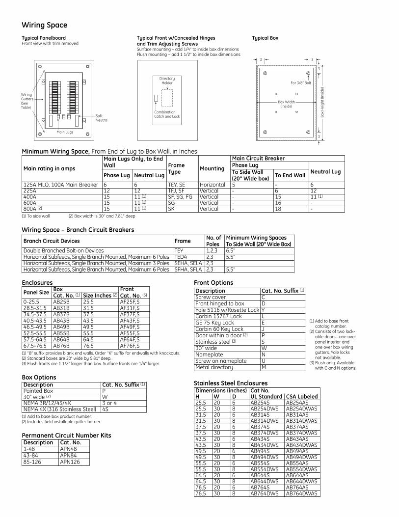
Wiring Space
Minimum Wiring Space, From End of Lug to Box Wall, in Inches
(1) To side wall (2) Box width is 30” and 7.81” deep
Wiring Space – Branch Circuit Breakers
Branch Circuit Devices Frame No. ofPoles
Minimum Wiring SpacesTo Side Wall (20" Wide Box)
Double Branched Bolt-on Devices TEY 1,2,3 6.5"Horizontal Subfeeds, Single Branch Mounted, Maximum 6 Poles TED4 2,3 5.5"Horizontal Subfeeds, Single Branch Mounted, Maximum 3 Poles SEHA, SELA 2,3Horizontal Subfeeds, Single Branch Mounted, Maximum 6 Poles SFHA, SFLA 2,3 5.5"
Main rating in amps
Main Lugs Only, to EndWall Frame
Type Mounting
Main Circuit BreakerPhase Lug
Neutral LugPhase Lug Neutral Lug To Side Wall
(20" Wide box) To End Wall
125A MLO, 100A Main Breaker 6 6 TEY, SE Horizontal 5 - 6225A 12 12 TFJ, SF Vertical - 6 12400A 15 11 (1) SF, SG, FG Vertical - 15 11 (1)
600A 15 11 (1) SG Vertical - 16 -800A (2) 15 11 (1) SK Vertical - 18 -
Typical PanelboardFront view with trim removed
Typical Front w/Concealed Hinges and Trim Adjusting ScrewsSurface mounting – add 1/4” to inside box dimensionsFlush mounting – add 1 1/2” to inside box dimensions
For 3/8” Bolt
Box Width(Inside)
Box
Hei
ght (
Insi
de)
3 3
3
3
Typical Box
Enclosures
(1) “B” suffix provides blank end walls. Order “K” suffix for endwalls with knockouts.(2) Standard boxes are 20" wide by 5.81" deep. (3) Flush fronts are 1 1/2" larger than box. Surface fronts are 1/4" larger.
Box Options
(1) Add to base box product number.(2) Includes field installable gutter barrier.
Permanent Circuit Number Kits
Front Options
Stainless Steel EnclosuresDimensions (inches) Cat No.H W D UL Standard CSA Labeled25.5 20 6 AB254S AB254AS 25.5 30 8 AB254DWS AB254DWAS 31.5 20 6 AB314S AB314AS 31.5 30 8 AB314DWS AB314DWAS 37.5 20 6 AB374S AB374AS 37.5 30 8 AB374DWS AB374DWAS 43.5 20 6 AB434S AB434AS 43.5 30 8 AB434DWS AB434DWAS 49.5 20 6 AB494S AB494AS 49.5 30 8 AB494DWS AB494DWAS 55.5 20 6 AB554S AB554AS 55.5 30 8 AB554DWS AB554DWAS 64.5 20 6 AB644S AB644AS 64.5 30 8 AB644DWS AB644DWAS 76.5 20 6 AB764S AB764AS 76.5 30 8 AB764DWS AB764DWAS
Description Cat. No. Suffix (1)
Screw cover CFront hinged to box DYale 5116 w/Rosette Lock YCorbin 15767 Lock LGE 75 Key Lock ECorbin 60 Key Lock JDoor within a door (2) PStainless steel (3) S 30” wide WNameplate NScrew on nameplate UMetal directory M
Description Cat. No.1-48 APN48 43-84 APN84 85-126 APN126
Description Cat. No. Suffix (1)
Painted Box P 30" wide (2) W NEMA 3R/12/4S/4X 3 or 4NEMA 4X (316 Stainless Steel) 4S
Panel Size Box Front Cat. No. (3)Cat. No. (1) Size Inches (2)
0-25.5 AB25B 25.5 AF25F,S 28.5-31.5 AB31B 31.5 AF31F,S 34.5-37.5 AB37B 37.5 AF37F,S 40.5-43.5 AB43B 43.5 AF43F,S 46.5-49.5 AB49B 49.5 AF49F,S 52.5-55.5 AB55B 55.5 AF55F,S 57.5-64.5 AB64B 64.5 AF64F,S 67.5-76.5 AB76B 76.5 AF76F,S
(1) Add to base frontcatalog number.
(2) Consists of two lock-able doors—one overpanel interior andone over box wiringgutters. Yale locksnot available.
(3) Flush only. Availablewith C and N options.

AccessoriesField Installed Kits/Replacement Parts
Filler Plates
Breaker Mounting Hardware KitsFor mounting breaker in existing space
Equipment Grounds
Bonding Kits
Installation & Maintenance KitOrder catalog number PROCARE. Kit includes:(5) filler plate hardware kits(9) bus stud nuts(5) MLA1 filler plates(2) 225A phase barriers(2) feed-thru barriers(1) 400/600A phase barrier(50) directory cards/rating books(50) circuit number strips (1-48)(50) circuit number strips (43-84)(5) standard locks & keys(50) deadfront screws(10) AQ/AE front hardware kits(10) AD front hardware kits(50) service disconnect labels(50) main labels
Parts
Box ExtensionsBolts to box with or without endwall in place. Extensions canbe combined to obtain lengths greater than 18 and 24 inches.
Box Extension Covers Only10 covers per kit Description Cat. No.9" Covers Surface ASPABX09S 9" Covers Flush ASPABX09F 18" Covers Surface ASPABX18S 18" Covers Flush ASPABX18F 64" to 76" Covers Surface ASPABX20S 64" to 76" Covers Flush ASPABX20F
Box Width andDepth Box Mounting Box Extension
Length (Inches) Cat. No.
20 x 5.81
Flush 9 ABX2509F 18 ABX2518F 24 ABX2524F
Surface
9 ABX2509S 18 ABX2518S 24 ABX2524S 31 ABX2531S 37 ABX2537S 43 ABX2543S 49 ABX2549S 55 ABX2555S 64 ABX2564S 76 ABX2576S
30 x 5.81 Flush 18 ABX3518F
24 ABX3524F
Surface 18 ABX3518S 24 ABX3524S
30 x 7.81 Flush 18 ABX3718F
24 ABX3724F
Surface 18 ABX3718S 24 ABX3724S
Description Cat. No.Directory Card 139C5612P3Replacement Lock with Std. Key 569B737P1Replacement Lock with GE75 Key 569B737P2Additional Keys for Above Lock 569B737P5Circuit Numbering Strips 1-48 569B806G1Circuit Numbering Strips 49-84 569B806G2Circuit Numbering Strips 85-126 569B806G3Adhesive Backed Lamicoid Nameplate 3/4" x 3" 315A7190P1Metal Directory Card Holder 139C5491G1Directory Card Holder 139C5491P4Delta Hi-leg Conversion Kit, to Add B-PhasePlug on AL Panels APHBL
Bolt on AE/AQ Panels APHBQNEMA 3R/12 Tamper Proof Tork Screw Kit NEMATRX2P to 3P TQD Conv. Kit ASP2PTQD3P 2P to 3P SF Conv. Kit for horizontal subfeed ASP2PTFJ3P AD 25 to 65 kAIC Barrier kit ASP25AD65KA1 Service Entrance Kit ASPSERENT2 wire Relay Kit ASP2WRelay Yale Lock Kit ASPYALE47 Corbin Lock Kit ASPCORBNTEU1 2-3 pole TQD Mechanical Interlock TQDFM1 AQ/AL/AE Rail Bracket ASPAQLEBKT Front Flush Adjust Kit ASPFLUSHADJAE Front Mounting Kit 139C5720G3AQ/AL Front Mounting Kit 139C5720G6 AD Front Mounting Kit 139C5728G9 Front Hinge to Box Mounting Kit 139C5700G6 Front Extension Mounting Kit 139C5700G11
Description Cat. No.For Split & Load End Neutral 343L886G16
For 225A Horizontal Neutrals 343L886G13
225A Horizontal Neutral To Convert 3W to 4W ASP225HNCP125/225A Horizontal Neutral Conversion fromService Entrance to Non-Service Entrance ASPHNCPSENOT
125/225A Horizontal Neutral to Convert fromNon-Service Entrance to Service Entrance. ASPHNCPSE
Item Description Wire Range Cat. No.
MetalEquipmentGround
Bonded#14-#8 Cu, #12-#8 Al(small holes); #14-#4 Cu,#6-#4 Al (large holes)
TGL2
Extruded Bonded#14-#8 Cu, #12-#8 Al(small holes); #14-#4 Cu,#6-#4 Al (large holes)
EGS12
AluminumEquipmentGround
Extruded Bonded (1) #6-350MCM AEBGExtruded Isolated (2) #6-250MCM AEIG
Main Lug#14-#8 Cu, #12-#8 Al(small holes); #14-#4 Cu,#6-#4 Al (large holes)
TGL2
CopperEquipmentGround
Bonded#14-#8 Cu, #12-#8 Al(small holes); #14-#4 Cu,#6-#4 Al (large holes)
TGC2
Extruded Bonded (1) #4-350MCM AEBGCExtruded Isolated (1) #6-250MCM AEIGCInsulated Isolated 2/0 max. ASPGIBC
Breaker Type Cat. No.TED/THED4/SE ASPTED3PTQD/THQD ASPTQD3PFB ASPFB12P
Breaker Type Cat. No.THQB/THHQB/THQL/THHQL/TEY TQLFP1TQD/THQD/TED4/SE/FB TEDFP1
AEBG
AEBGC
AEIG
AEIGC
ASPGIBC
Endwall KitsField installed. 1 each, for standard 20"w x5.81"d boxes.
Type Cat. No.Blank ABEW2Knockout ABEW2
imagination at work
GE41 Woodford Avenue, Plainville, CT 06062www.geelectrical.com
© 2008 General Electric Company
DE-43A REV 02 (6/08)
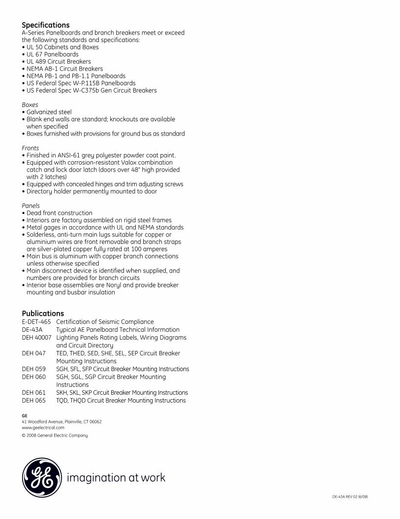
SpecificationsA-Series Panelboards and branch breakers meet or exceedthe following standards and specifications:• UL 50 Cabinets and Boxes• UL 67 Panelboards• UL 489 Circuit Breakers• NEMA AB-1 Circuit Breakers• NEMA PB-1 and PB-1.1 Panelboards• US Federal Spec W-P.115B Panelboards• US Federal Spec W-C375b Gen Circuit Breakers
Boxes• Galvanized steel• Blank end walls are standard; knockouts are available
when specified• Boxes furnished with provisions for ground bus as standard
Fronts• Finished in ANSI-61 grey polyester powder coat paint.• Equipped with corrosion-resistant Valox combination
catch and lock door latch (doors over 48" high providedwith 2 latches)
• Equipped with concealed hinges and trim adjusting screws• Directory holder permanently mounted to door
Panels• Dead front construction• Interiors are factory assembled on rigid steel frames• Metal gages in accordance with UL and NEMA standards• Solderless, anti-turn main lugs suitable for copper or
aluminium wires are front removable and branch strapsare silver-plated copper fully rated at 100 amperes
• Main bus is aluminum with copper branch connectionsunless otherwise specified
• Main disconnect device is identified when supplied, andnumbers are provided for branch circuits
• Interior base assemblies are Noryl and provide breakermounting and busbar insulation
PublicationsE-DET-465 Certification of Seismic ComplianceDE-43A Typical AE Panelboard Technical InformationDEH 40007 Lighting Panels Rating Labels, Wiring Diagrams
and Circuit DirectoryDEH 047 TED, THED, SED, SHE, SEL, SEP Circuit Breaker
Mounting InstructionsDEH 059 SGH, SFL, SFP Circuit Breaker Mounting InstructionsDEH 060 SGH, SGL, SGP Circuit Breaker Mounting
InstructionsDEH 061 SKH, SKL, SKP Circuit Breaker Mounting InstructionsDEH 065 TQD, THQD Circuit Breaker Mounting Instructions

imagination at work
Typical AQ/AL PanelboardInstallationConsult instructions NEMA PB-1.1 located in the circuit directory on the front door before installing this panelboard.If necessary, order replacement manual from supplier.
Wiring Guidelines (Cu or Al)• Use 60°C or 75°C ampacity sized wire on line and neutral
and equipment ground terminals.• Standard wire sizes listed in this publication may be
changed by using alternate terminal kits.• Refer to circuit breakers for allowable wire temperature
rating, wire size and tightening torque.• Neutral rated for 200% panelboard phase current option.
• Use copper wire only at neutral main lugs- 125A (1) neutral cables 250 mcm maximum- 225A (2) neutral cables 250 mcm maximum- 400A (2) neutral cables 600 mcm maximum- 600A (4) neutral cables 350 mcm maximum
Suitable for nonlinear loads, 200% rated neutral, additional“Y” lugs provided for 200% neutral.
Short Circuit Current RatingThe panelboard’s maximum short circuit interrupting ratingin rms symmetrical amperes, is equal to the lowest inter-rupting rating of any device installed, except as noted in theseries rating listed in DEH-40007, with integral or remotemain circuit breaker or fusible switch installed upstream ofthe panelboard. Devices to be installed or replacement unitsshall be from the same manufacturer, of the same type, andhave equal or greater interrupting capacity.
Maximum continuous loads on main or branch circuits shallnot exceed 80% of the ratings of the listed circuit breakers.Branch breaker straps suitable for 180A maximum.
Tripped BreakerIf the breaker trips, handle will be in intermediate position.
Instructions To Restore Power1. Move handle to OFF position.2. Then move handle to ON position.
Seismic RatingMeets or Exceeds the Requirements According to• IEEE-693-2005
High Level with 1.8 Amplication Factor• IBC-2006
Sds = 1.3g, Ss = 200%, Ip = 1.5, for z/h > 0Sds = 2.0g, Ss = 300%, Ip = 1.5, for z/h = 0In accordance with ICC-ES-AC156
Polybag ContentsA polybag of goods supplied with every panelboard interiorcontains:• Arc flash label• DEH-40007 Series Ratings, Wiring Diagrams &
Circuit Directory• Series rating sticker• Front installation instructions• ANSI PB1 documentation• Circuit numbering stickers (1-84)• Front and shield mounting screws

Torque
Tightening Torque Torque Values for HardwareApplies to line, neutral and equipment ground terminal
Lug Kits
Lug Kits for A-Series II Panelboards
Crimp Tools
Neutral Lug Z
Arc fault label included with all interiors tobe applied by electrical contractor.
Holes Wire Size – Cu / AlLarge 2 / 0 - 14Small No. 4 – 14
Wire Crimp ToolAll Al & Up to 500 MCM Cu Hubbell Anderson VC6500-750 MCM Cu Hubbell Anderson VC7Up to #6-1000 MCM Cu & #5-750 Kcmil Al Burndy Tool Y644HS
Rating Pressure Lug Kit Crimp Lug Kit Pressure Lug KitCat. No. Wire Range Al/Cu Cat. No. Wire Range Al/Cu Cat. No. Wire Range Cu Only
125A MLA1 6-350 MLT1 4-300 MLR1 4-350225A MLA2 1/0-250 MLT2 2/0 - 500 MLR2 1/0-600
400A Standard - MLA41 4-600 MLT41 500-750 (Cu Only) MLR41 1/0-600Oversize – MLA62 3/0 - 800 (Main) & 4-600 (Neutral) - - - -
600A Standard -MLA61 4-500 - - MLR61 1/0-600
Screw Size Torque (In-Lbs)#4 Steel 16#10 Plastic 16#8 Cu/Al/Steel 24#10-32 Cu/Al/Steel 321/4-20 Al/<.150 Thick Cu 441/4-20 .150 Thick Cu 605/16-18 Cu/Al/Steel 1103/8-16 Cu/Al/Steel 2201/2-13 Cu/Al/Steel 220
Internal HexHexSize
Lbs-InsMin Max
3/16 108 1201/4 180 2005/16 240 2753/8 330 3751/2 450 500
Slotted ScrewAWGWire
Lbs-InsMin Max
14-10 32 358 36 406-4 41 453-2/0 45 50
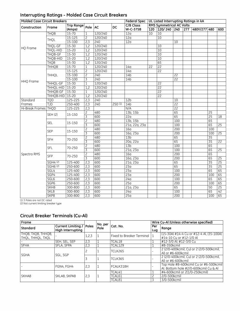
Interrupting Ratings - Molded Case Circuit Breakers
(1) 3 Poles are not DC rated(2) Not current limiting breaker type
Circuit Breaker Terminals (Cu-Al)Frame
Poles No. perPole Cat. No.
Wire Cu-Al (Unless otherwise specified)
Standard Current Limiting /High Interrupting
PerLug Range
THQB, TXQB, THHQB,THQL, THHQL, TXQL - 1,2,3 1 Fixed to Breaker Terminal 1 (15-30A) #14-4 Cu or #12-4 Al, (35-100A)
#14-10 Cu or #12-1/0 Al- SEH, SEL, SEP 2,3 1 TCAL18 1 #12-3/0 Al; #12-3/0 CuSFHA SFLA, SFPA 2,3 1 TCAL129 1 #8-350kcmil
SGHA SGL, SGP2 1 TCLK265 - 2 (2/0-400kcmil, Cu) or 2 (2/0-500kcmil,
Al) or #6-600kcmil
3 1 TCLK365 - 2 (2/0-400kcmil, Cu) or 2 (2/0-500kcmil,Al) or #6-600kcmil
- FGN4, FGH4 2,3 1 FCALK318H - Top Hole #8-400kcmil Cu or #6-500kcmilAl. Bottom hole #2/0-600kcmil Cu & Al
SKHA8 SKLA8, SKPA8 2,3 1TCAL41 1 #4-600kcmil or 2(1/0-250kcmil)TCAL61 2 2/0-500kcmilTCAL81 3 3/0-500kcmil
Molded Case Circuit Breakers Federal Spec UL Listed Interrupting Ratings in kA
Construction Frame Trip Range(Amps) Pole AC DC C/B Class
W-C-375BRMS Symmetrical AC Volts120 120/ 240 240 277 480Y/277 480 600
HQ Frame
THQB 15-70 1 120/240 12a 10 10
THQL15-125 2 120/240 12a 1015-100 2,3 240 12a 10
THQL-GF 15-30 1,2 120/240 10THQL-HID 15-20 1,2 120/240 10THQB-GF 15-30 1,2 120/240 10THQB-HID 15-20 1,2 120/240 10TXQB 15-30 1,2 120/240 65
HHQ Frame
THHQB 15-70 1 120/240 14a 22 22
THHQL15-125 2 120/240 14a 2215-100 2 240 14b 2215-100 3 240 14b 22
THHQL-GF 15-30 1 120/240 22THHQL-HID 15-20 1,2 120/240 22THHQB-GF 15-30 1 120/240 22THHQB-HID 15-20 1,2 120/240 22
StandardFrames
TQD 125-225 2,3 240 12b 10TJD 250-400 2,3 240 250 (1) 14b 22
Hi-Break Frames THQD 125-225 2,3 N/A 22
Spectra RMS
SEH (2) 15-1502 480 13b, 15b 65 253 600 22a 65 25 18
SEL 15-1502 480 13b, 15b 100 653 600 21a, 22a, 23a 100 65 25
SEP 15-1502 480 16a 200 1003 600 16a, 23a 200 100 25
SFH 70-2502 480 13b 65 353 600 20a, 22a 65 35 22
SFL 70-2502 480 13b 100 653 600 21a, 23a 100 65 25
SFP 70-2502 480 16a 200 653 600 16a, 23a 200 65 25
SGH4 (2) 125-400 2,3 600 21a, 23a 65 35 25SGH6 (2) 250-600 2,3 600 23a 65 35 25SGL4 125-400 2,3 600 23a 100 65 65SGP4 125-400 2,3 600 23a 200 100 65SGL6 250-600 2,3 600 24a 100 65 65SGP6 250-600 2,3 600 25a 200 100 65SKH8 300-800 2,3 600 21a, 23a 65 50 25SKL8 300-800 2,3 600 24a 100 65 42SKP8 300-800 2,3 600 25a 200 100 65

Wiring Space
Minimum Wiring Space, From End of Lug to Box Wall, in Inches
(1) To side wall (2) Box width is 30” and 7.81” deep
Wiring Space – Branch Circuit Breakers
Branch Circuit Devices Frame No. of Poles Minimum Wiring Spaces ToSide Wall (20" Wide Box)
Double Branched Bolt-on Devices THQL, THHQL, THQB, THHQB 1,2,3 6.5"Horizontal Subfeeds Single Branch Mounted TQD, THQD 2,3 5.5"
Main rating in amps
Main Lugs Only, toEnd Wall Frame
Type Mounting
Main Circuit BreakerPhase Lug Neutral Lug
Phase Lug Neutral Lug To Side Wall(20" Wide box) To End Wall
125A MLO, 100A Main Breaker 6 6 TEY, SE Horizontal 5 - 6225A 12 12 TFJ, SF Vertical - 6 12400A 15 11 (1) SF, SG, FG Vertical - 15 11 (1)
600A 15 11 (1) SG Vertical - 16 -800A (2) 15 11 (1) SK Vertical - 18 -
Typical PanelboardFront view with trim removed
Typical Front w/Concealed Hinges and Trim Adjusting ScrewsSurface mounting – add 1/4” to inside box dimensionsFlush mounting – add 1 1/2” to inside box dimensions
For 3/8” Bolt
Box Width(Inside)
Box
Hei
ght (
Insi
de)
3 3
3
3
Typical Box
Enclosures
(1) “B” suffix provides blank end walls. Order “K” suffix for endwalls with knockouts.(2) Standard boxes are 20" wide by 5.81" deep. (3) Flush fronts are 1 1/2" larger than box. Surface fronts are 1/4" larger.
Box Options
(1) Add to base box product number.(2) Includes field installable gutter barrier.
Permanent Circuit Number Kits
Front Options
Stainless Steel EnclosuresDimensions (inches) Cat No.H W D UL Standard CSA Labeled25.5 20 6 AB254S AB254AS 25.5 30 8 AB254DWS AB254DWAS 31.5 20 6 AB314S AB314AS 31.5 30 8 AB314DWS AB314DWAS 37.5 20 6 AB374S AB374AS 37.5 30 8 AB374DWS AB374DWAS 43.5 20 6 AB434S AB434AS 43.5 30 8 AB434DWS AB434DWAS 49.5 20 6 AB494S AB494AS 49.5 30 8 AB494DWS AB494DWAS 55.5 20 6 AB554S AB554AS 55.5 30 8 AB554DWS AB554DWAS 64.5 20 6 AB644S AB644AS 64.5 30 8 AB644DWS AB644DWAS 76.5 20 6 AB764S AB764AS 76.5 30 8 AB764DWS AB764DWAS
Description Cat. No. Suffix (1)
Screw cover CFront hinged to box DYale 5116 w/Rosette Lock YCorbin 15767 Lock LGE 75 Key Lock ECorbin 60 Key Lock JDoor within a door (2) PStainless steel (3) S 30” wide WNameplate NScrew on nameplate UMetal directory M
Description Cat. No.1-48 APN48 43-84 APN84 85-126 APN126
Description Cat. No. Suffix (1)
Painted Box P 30" wide (2) W NEMA 3R/12/4S/4X 3 or 4 NEMA 4X (316 Stainless Steel) 4S
Panel Size Box Front Cat. No. (3)Cat. No. (1) Size Inches (2)
0-25.5 AB25B 25.5 AF25F,S 28.5-31.5 AB31B 31.5 AF31F,S 34.5-37.5 AB37B 37.5 AF37F,S 40.5-43.5 AB43B 43.5 AF43F,S 46.5-49.5 AB49B 49.5 AF49F,S 52.5-55.5 AB55B 55.5 AF55F,S 57.5-64.5 AB64B 64.5 AF64F,S 67.5-76.5 AB76B 76.5 AF76F,S
(1) Add to base frontcatalog number.
(2) Consists of two lock-able doors—one overpanel interior andone over box wiringgutters. Yale locksnot available.
(3) Flush only. Availablewith C and N options.

AccessoriesField Installed Kits/Replacement Parts
Filler Plates
Breaker Mounting Hardware KitsFor mounting breaker in existing space
Equipment Grounds
Bonding Kits
Installation & Maintenance KitOrder catalog number PROCARE. Kit includes:(5) filler plate hardware kits(9) bus stud nuts(5) MLA1 filler plates(2) 225A phase barriers(2) feed-thru barriers(1) 400/600A phase barrier(50) directory cards/rating books(50) circuit number strips (1-48)(50) circuit number strips (43-84)(5) standard locks & keys(50) deadfront screws(10) AQ/AE front hardware kits(10) AD front hardware kits(50) service disconnect labels(50) main labels
Parts
Box ExtensionsBolts to box with or without endwall in place. Extensions canbe combined to obtain lengths greater than 18 and 24 inches.
Box Extension Covers Only10 covers per kit Description Cat. No.9" Covers Surface ASPABX09S 9" Covers Flush ASPABX09F 18" Covers Surface ASPABX18S 18" Covers Flush ASPABX18F 64" to 76" Covers Surface ASPABX20S 64" to 76" Covers Flush ASPABX20F
Box Width andDepth Box Mounting Box Extension
Length (Inches) Cat. No.
20 x 5.81
Flush 9 ABX2509F 18 ABX2518F 24 ABX2524F
Surface
9 ABX2509S 18 ABX2518S 24 ABX2524S 31 ABX2531S 37 ABX2537S 43 ABX2543S 49 ABX2549S 55 ABX2555S 64 ABX2564S 76 ABX2576S
30 x 5.81 Flush 18 ABX3518F
24 ABX3524F
Surface 18 ABX3518S 24 ABX3524S
30 x 7.81 Flush 18 ABX3718F
24 ABX3724F
Surface 18 ABX3718S 24 ABX3724S
Description Cat. No.Directory Card 139C5612P3Replacement Lock with Std. Key 569B737P1Replacement Lock with GE75 Key 569B737P2Additional Keys for Above Lock 569B737P5Circuit Numbering Strips 1-48 569B806G1Circuit Numbering Strips 49-84 569B806G2Circuit Numbering Strips 85-126 569B806G3Adhesive Backed Lamicoid Nameplate 3/4" x 3" 315A7190P1Metal Directory Card Holder 139C5491G1Directory Card Holder 139C5491P4Delta Hi-leg Conversion Kit, to Add B-PhasePlug on AL Panels APHBL
Bolt on AE/AQ Panels APHBQNEMA 3R/12 Tamper Proof Tork Screw Kit NEMATRX2P to 3P TQD Conv. Kit ASP2PTQD3P 2P to 3P SF Conv. Kit for horizontal subfeed ASP2PTFJ3P AD 25 to 65 kAIC Barrier kit ASP25AD65KA1 Service Entrance Kit ASPSERENT2 wire Relay Kit ASP2WRelay Yale Lock Kit ASPYALE47 Corbin Lock Kit ASPCORBNTEU1 2-3 pole TQD Mechanical Interlock TQDFM1 AQ/AL/AE Rail Bracket ASPAQLEBKT Front Flush Adjust Kit ASPFLUSHADJAE Front Mounting Kit 139C5720G3AQ/AL Front Mounting Kit 139C5720G6 AD Front Mounting Kit 139C5728G9 Front Hinge to Box Mounting Kit 139C5700G6 Front Extension Mounting Kit 139C5700G11
Description Cat. No.For Split & Load End Neutral 343L886G16
For 225A Horizontal Neutrals 343L886G13
225A Horizontal Neutral To Convert 3W to 4W ASP225HNCP125/225A Horizontal Neutral Conversion fromService Entrance to Non-Service Entrance ASPHNCPSENOT
125/225A Horizontal Neutral to Convert fromNon-Service Entrance to Service Entrance. ASPHNCPSE
Item Description Wire Range Cat. No.
MetalEquipmentGround
Bonded#14-#8 Cu, #12-#8 Al(small holes); #14-#4 Cu,#6-#4 Al (large holes)
TGL2
Extruded Bonded#14-#8 Cu, #12-#8 Al(small holes); #14-#4 Cu,#6-#4 Al (large holes)
EGS12
AluminumEquipmentGround
Extruded Bonded (1) #6-350MCM AEBGExtruded Isolated (2) #6-250MCM AEIG
Main Lug#14-#8 Cu, #12-#8 Al(small holes); #14-#4 Cu,#6-#4 Al (large holes)
TGL2
CopperEquipmentGround
Bonded#14-#8 Cu, #12-#8 Al(small holes); #14-#4 Cu,#6-#4 Al (large holes)
TGC2
Extruded Bonded (1) #4-350MCM AEBGCExtruded Isolated (1) #6-250MCM AEIGCInsulated Isolated 2/0 max. ASPGIBC
Breaker Type Cat. No.TED/THED4/SE ASPTED3PTQD/THQD ASPTQD3PFB ASPFB12P
Breaker Type Cat. No.THQB/THHQB/THQL/THHQL/TEY TQLFP1TQD/THQD/TED4/SE/FB TEDFP1
AEBG
AEBGC
AEIG
AEIGC
ASPGIBC
Endwall KitsField installed. 1 each, for standard 20"w x5.81"d boxes.
Type Cat. No.Blank ABEW2Knockout ABEW2

imagination at work
GE41 Woodford Avenue, Plainville, CT 06062www.geelectrical.com
© 2008 General Electric Company
DE-42A REV 02 (6/08)
SpecificationsA-Series Panelboards and branch breakers meet or exceedthe following standards and specifications:• UL 50 Cabinets and Boxes• UL 67 Panelboards• UL 489 Circuit Breakers• NEMA AB-1 Circuit Breakers• NEMA PB-1 and PB-1.1 Panelboards• US Federal Spec W-P.115B Panelboards• US Federal Spec W-C375b Gen Circuit Breakers
Boxes• Galvanized steel• Blank end walls are standard; knockouts are available
when specified• Boxes furnished with provisions for ground bus as standard
Fronts• Finished in ANSI-61 grey polyester powder coat paint.• Equipped with corrosion-resistant Valox combination
catch and lock door latch (doors over 48" high providedwith 2 latches)
• Equipped with concealed hinges and trim adjusting screws• Directory holder permanently mounted to door
Panels• Dead front construction• Interiors are factory assembled on rigid steel frames• Metal gages in accordance with UL and NEMA standards• Solderless, anti-turn main lugs suitable for copper or
aluminium wires are front removable and branch strapsare silver-plated copper fully rated at 100 amperes
• Main bus is aluminum with copper branch connectionsunless otherwise specified
• Main disconnect device is identified when supplied, andnumbers are provided for branch circuits
• Interior base assemblies are Noryl and provide breakermounting and busbar insulation
PublicationsE-DET-465 Certification of Seismic ComplianceDE-42A Typical AL/AQ Panelboard Technical InformationDEH 40007 Lighting Panels Rating Labels, Wiring Diagrams
and Circuit DirectoryDEH 047 TED, THED, SED, SHE, SEL, SEP Circuit Breaker
Mounting InstructionsDEH 059 SGH, SFL, SFP Circuit Breaker Mounting InstructionsDEH 060 SGH, SGL, SGP Circuit Breaker Mounting
InstructionsDEH 061 SKH, SKL, SKP Circuit Breaker Mounting InstructionsDEH 065 TQD, THQD Circuit Breaker Mounting Instructions

Approved as an American National Standard
ANSI Approval Date: June 14, 2010
ANSI/NEMA PB 1.1-2007
General Instructions for Proper Installation, Operation, and Maintenance
of Panelboards Rated 600 Volts or Less Published by National Electrical Manufacturers Association 1300 North 17th Street Rosslyn, Virginia 22209 www.nema.org © Copyright 2007 by the National Electrical Manufacturers Association. All rights including translation into other languages, reserved under the Universal Copyright Convention, the Berne Convention for the Protection of Literary and Artistic Works, and the International and Pan American Copyright Conventions.

NOTICE AND DISCLAIMER The information in this publication was considered technically sound by the consensus of persons engaged in the development and approval of the document at the time it was developed. Consensus does not necessarily mean that there is unanimous agreement among every person participating in the development of this document. The National Electrical Manufacturers Association (NEMA) standards and guideline publications, of which the document contained herein is one, are developed through a voluntary consensus standards development process. This process brings together volunteers and/or seeks out the views of persons who have an interest in the topic covered by this publication. While NEMA administers the process and establishes rules to promote fairness in the development of consensus, it does not write the document and it does not independently test, evaluate, or verify the accuracy or completeness of any information or the soundness of any judgments contained in its standards and guideline publications. NEMA disclaims liability for any personal injury, property, or other damages of any nature whatsoever, whether special, indirect, consequential, or compensatory, directly or indirectly resulting from the publication, use of, application, or reliance on this document. NEMA disclaims and makes no guaranty or warranty, expressed or implied, as to the accuracy or completeness of any information published herein, and disclaims and makes no warranty that the information in this document will fulfill any of your particular purposes or needs. NEMA does not undertake to guarantee the performance of any individual manufacturer or seller’s products or services by virtue of this standard or guide. In publishing and making this document available, NEMA is not undertaking to render professional or other services for or on behalf of any person or entity, nor is NEMA undertaking to perform any duty owed by any person or entity to someone else. Anyone using this document should rely on his or her own independent judgment or, as appropriate, seek the advice of a competent professional in determining the exercise of reasonable care in any given circumstances. Information and other standards on the topic covered by this publication may be available from other sources, which the user may wish to consult for additional views or information not covered by this publication. NEMA has no power, nor does it undertake to police or enforce compliance with the contents of this document. NEMA does not certify, test, or inspect products, designs, or installations for safety or health purposes. Any certification or other statement of compliance with any health or safety–related information in this document shall not be attributable to NEMA and is solely the responsibility of the certifier or maker of the statement.

PB 1.1-2007 Page i
CONTENTS Page
Foreword ...................................................................................................................................iv Section 1 SCOPE ...................................................................................................................................... 1 Section 2 REFERENCES .......................................................................................................................... 2 Section 3 GENERAL ................................................................................................................................. 3
3.1 Successful Operation of Panelboards....................................................................................... 3 3.2 Qualified Personnel ................................................................................................................... 3 3.3 Definition of Qualified Personnel ............................................................................................... 3
3.3.1 Requirements................................................................................................................ 3 3.3.2 Established Safety Practices......................................................................................... 3 3.3.3 Protective Equipment .................................................................................................... 3 3.3.4 First Aid ......................................................................................................................... 3
3.4 Suitable Ratings ........................................................................................................................ 3 Section 4 INSTALLATION OF PANELBOARD CABINETS (BOXES) .................................................... 4
4.1 Installation Instructions .............................................................................................................. 4 4.2 Location in Building ................................................................................................................... 4 4.3 Flammable Material ................................................................................................................... 4 4.4 Unusual Service Conditions ...................................................................................................... 4 4.5 Indoor Damp Locations ............................................................................................................. 4 4.6 Wet Locations............................................................................................................................ 4 4.7 Clearance from Ceiling.............................................................................................................. 4 4.8 Space around the Cabinet......................................................................................................... 4 4.9 Mounting of Cabinet .................................................................................................................. 4 4.10 Flush Mounting in Wall .............................................................................................................. 5 4.11 Unused Openings in Cabinet .................................................................................................... 5 4.12 Grounding of Panelboard Cabinets ........................................................................................... 5
Section 5 INSTALLATION OF CONDUIT AND CONDUCTORS............................................................. 6 5.1 Conduits Installation .................................................................................................................. 6 5.2 Knockouts Removal................................................................................................................... 6
5.2.1 First Step—Remove Center Knockout.......................................................................... 6 5.2.2 Next Step—Remove Rings ........................................................................................... 6
5.3 National Electrical Code, Article 300......................................................................................... 6 5.4 Conductor Length ...................................................................................................................... 6 5.5 Exercise Care ............................................................................................................................ 6 5.6 National Electrical Code, Section 725.54.................................................................................. 7
Section 6 INSTALLATION OF PANELBOARD...................................................................................... 11 6.1 Proper Storage ........................................................................................................................ 11 6.2 Unpacking................................................................................................................................ 11 6.3 Inspection ................................................................................................................................ 11 6.4 Care ......................................................................................................................................... 11
6.4.1 Cleaning ...................................................................................................................... 11 6.5 Manufacturer's Instructions ..................................................................................................... 11 6.6 Installation................................................................................................................................ 11
6.6.1 Alignment Devices ...................................................................................................... 11 6.6.2 Panelboard.................................................................................................................. 11 6.6.3 Flange of Deadfront Shield ......................................................................................... 11
6.7 Line And Branch Conductors .................................................................................................. 12 6.7.1 Conductors .................................................................................................................. 12
6.8 Panelboard Grounding ............................................................................................................ 12 6.8.1 Equipment Grounding Conductors.............................................................................. 12
6.9 Proper Type Or Class And Rating........................................................................................... 12
© Copyright 2007 by the National Electrical Manufacturers Association.

PB 1.1-2007 Page ii
6.10 Debris ...................................................................................................................................... 12 6.11 Steps In Section 7 ................................................................................................................... 12
Section 7 STEPS TO BE TAKEN BEFORE ENERGIZING.................................................................... 13 7.1 Accessible Electrical Connections........................................................................................... 13 7.2 Blocks and Packing Materials ................................................................................................. 13 7.3 Switches, Circuit Breakers, and Other Operating Mechanisms.............................................. 13 7.4 Short Circuits and Ground Faults ............................................................................................ 13 7.5 Ground Fault Protection System ............................................................................................. 13 7.6 Adjustable Time Current Trip Device Settings ........................................................................ 13 7.7 Grounding Connections........................................................................................................... 13 7.8 Foreign Material....................................................................................................................... 14
Section 8 INSTALLATION OF CABINET FRONT.................................................................................. 15 8.1 Cabinet Front or Trim Package ............................................................................................... 15 8.2 Unpacking................................................................................................................................ 15 8.3 Covers and Doors.................................................................................................................... 15 8.4 Touch-Up................................................................................................................................. 15 8.5 Front Alignment ....................................................................................................................... 15
Section 9 ENERGIZING EQUIPMENT.................................................................................................... 16 9.1 Qualified Personnel ................................................................................................................. 16 9.2 Load on the Panelboard .......................................................................................................... 16 9.3 Energized in Sequence ........................................................................................................... 16 9.4 Loads Such as Lighting Circuits, Contactors, Heaters, and Motors ....................................... 16
Section 10 MAINTENANCE ...................................................................................................................... 17 10.1 Maintenance Program ............................................................................................................. 17 10.2 Panelboard Which Has Been Carrying Its Regular Load for at Least 3 Hours ....................... 17 10.3 Inspect Panelboard Once Each Year ...................................................................................... 17 10.4 Accumulation of Dust and Dirt ................................................................................................. 17
10.4.1 Visible Electrical Joints and Terminals...................................................................... 17 10.4.2 Conductors and Connections.................................................................................... 17 10.4.3 Fuse Clip Contact Pressure and Contact Means...................................................... 18 10.4.4 Plug Fuses ................................................................................................................ 18 10.4.5 Conditions Which Caused Overheating.................................................................... 18
10.5 Proper Ampere, Voltage, and Interrupting Ratings ................................................................. 18 10.5.1 Mechanisms Free and in Proper Working Order ...................................................... 18
10.6 Operation of all Mechanical Components ............................................................................... 18 10.6.1 Switch Operating Mechanisms ................................................................................. 18 10.6.2 Integrity of Electrical and Mechanical Interlocks....................................................... 18 10.6.3 Missing or Broken Parts ............................................................................................ 18 10.6.4 Manufacturer’s Instructions....................................................................................... 18 10.6.5 Accessible Copper Electrical Contacts, Blades, and Jaws....................................... 19
10.7 Damaged Insulating Material and Assemblies ........................................................................ 19 10.8 Moisture or Signs of Previous Wetness or Dripping................................................................ 19
10.8.1 Conduits Which Have Dripped Condensate ............................................................. 19 10.8.2 Cracks or Openings .................................................................................................. 19 10.8.3 Insulating Material Which is Damp or Wet ................................................................ 19 10.8.4 Component Devices Which Show Evidence of Moisture Damage ........................... 19
10.9 Before Cleanup and Corrective Action is Attempted............................................................... 19 10.10 Severe Electrical Short Circuit................................................................................................. 20 10.11 Ground Fault Protection System ............................................................................................. 20 10.12 Insulation Resistance .............................................................................................................. 20
10.12.1 Severe Short Circuit ................................................................................................ 20 10.12.2 Parts Replaced........................................................................................................ 20 10.12.3 Panelboard Exposed to High Humidity ................................................................... 20
© Copyright 2007 by the National Electrical Manufacturers Association.

PB 1.1-2007 Page iii
Section 11 PERMISSIBLE LOADING OF PANELBOARDS ................................................................... 21 11.1 National Electrical Code .......................................................................................................... 21 11.2 Harmonics in Electrical System............................................................................................... 21
Figures
5–1 Knockout Removal—Step 1 ...................................................................................................... 8 5–2 Knockout Removal—Step 2 ...................................................................................................... 9 5–3 Knockout Removal—Step 3 .................................................................................................... 10
© Copyright 2007 by the National Electrical Manufacturers Association.
PB 1.1-2007 Page iv
© Copyright 2007 by the National Electrical Manufacturers Association.
Foreword
This publication is a guide of practical information containing instructions for the proper installation, operation, and maintenance of panelboards rated 600 volts or less. These instructions do not purport to cover all details or variations in equipment, nor to provide for every possible contingency regarding installation, operation, or maintenance. It is recommended that work described in this set of instructions be performed only by qualified personnel familiar with the construction and operation of panelboards and that such work be performed only after reading this complete set of instructions. For specific information not covered by these instructions, you are urged to contact the manufacturer of the panelboard directly. In the preparation of this Standards Publication input of users and other interested parties has been sought and evaluated. Inquiries, comments, and proposed or recommended revisions should be submitted to the concerned NEMA product section by contacting the following: These recommendations will be reviewed periodically and updated as necessary.
Vice President, Technical Services National Electrical Manufacturers Association 1300 North 17th Street, Suite 1752 Rosslyn, Virginia 22209
Publication No. PB 1.1- 2007 revises and supersedes PB 1.1-2002. This Standards Publication was developed by the Panelboard and Distribution Board Product Group of the LVDE Section. Product Group approval of the standard does not necessarily imply that all Product Group members voted for its approval or participated in its development. At the time it was approved, the Product Group was composed of the following members:
Eaton Electrical Inc.—Pittsburgh, PA GE—Plainville, CT Hubbell, Inc.—Orange, CT Milbank Manufacturing Company—Kansas City, MO Penn Panel & Box Company—Collingdale, PA Reliance Controls Corporation—Racine, WI Siemens Industry, Inc.—Norcross, GA Square D Company—Palatine, IL

PB 1.1-2007 Page 1
Section 1 SCOPE
This publication covers single panelboards or groups of panel units suitable for assembly in the form of single panelboards, including buses, and with or without switches or automatic overload protective devices (fuses or circuit breakers), or both. These units are used in the distribution of electricity at 600 volts and less with: 1600—ampere mains or less 1200—ampere branch circuits or less Specifically excluded are live-front panelboards, panelboards employing cast enclosures for special service conditions, and panelboards designed primarily for residential and light commercial service equipment.
© Copyright 2007 by the National Electrical Manufacturers Association.

PB 1.1-2007 Page 2
Section 2 REFERENCES
National Fire Protection Association (NFPA)
Batterymarch Park Quincy, MA 02269
NFPA 70 2005 National Electrical Code NFPA 70E 2004 Safety Related Work Practices
National Electrical Manufacturers Association (NEMA) 1300 North 17th Street, Suite 1752
Rosslyn, Virginia 22209 AB 4- 2003 Guidelines for Inspection and Preventative Maintenance of Molded Case Circuit Breakers Used in Commercial and Industrial Applications PB 2.2- 2004 Application Guide for Ground Fault Protective Devices for Equipment Guidelines for Handling Water Damaged Electrical Products
© Copyright 2007 by the National Electrical Manufacturers Association.

PB 1.1-2007 Page 3
Section 3 GENERAL
WARNING—HAZARDOUS VOLTAGES IN ELECTRICAL EQUIPMENT CAN CAUSE SEVERE PERSONAL INJURY OR DEATH. UNLESS OTHERWISE SPECIFIED, INSPECTION AND MAINTENANCE SHOULD ONLY BE PERFORMED ON PANELBOARDS AND EQUIPMENT TO WHICH POWER HAS BEEN TURNED OFF, DISCONNECTED AND ELECTRICALLY ISOLATED SO THAT NO ACCIDENTAL CONTACT CAN BE MADE WITH ENERGIZED PARTS. FOLLOW ALL MANUFACTURER'S WARNINGS AND INSTRUCTIONS. Safety-related work practices, as described in NFPA 70E, should be followed at all times. CAUTION—Hydrocarbon spray propellants and hydrocarbon based sprays or compounds will cause degradation of certain plastics. Contact the panelboard manufacturer before using these products to clean, dry, or lubricate components during installation or maintenance. 3.1 SUCCESSFUL OPERATION OF PANELBOARDS
The successful operation of panelboards is dependent upon proper installation, operation, and maintenance. Neglecting fundamental installation and maintenance requirements may lead to personal injury, death, or damage to electrical equipment or other property. 3.2 QUALIFIED PERSONNEL
Installation, operation, and maintenance of panelboards should be conducted only by qualified personnel. 3.3 DEFINITION OF QUALIFIED PERSONNEL
For purposes of these guidelines, a qualified person is one who is familiar with the installation, construction, and operation of the equipment and the hazards involved. In addition, the person is: 3.3.1 Requirements
Knowledgeable of the requirements of the National Electrical Code and of all other applicable codes, laws, and standards. 3.3.2 Established Safety Practices
Trained and authorized to test, energize, clear, ground, tag, and lockout circuits and equipment in accordance with established safety practices. 3.3.3 Protective Equipment
Trained in the proper care and use of protective equipment such as rubber gloves, hard hat, safety glasses or face shields, and flash resistant clothing in accordance with established safety practices. 3.3.4 First Aid
Trained in rendering first aid. 3.4 SUITABLE RATINGS
Verify that all equipment being installed has ratings suitable for the installation.
© Copyright 2007 by the National Electrical Manufacturers Association.

PB 1.1-2007 Page 4
Section 4 INSTALLATION OF PANELBOARD CABINETS (BOXES)
4.1 INSTALLATION INSTRUCTIONS
Installation of the cabinet in a neat and workmanlike manner. Follow the manufacturer's installation instructions. 4.2 LOCATION IN BUILDING
Locate the cabinet so that it is readily accessible and not exposed to physical damage. 4.3 FLAMMABLE MATERIAL
Locate the cabinet well away from flammable material. 4.4 UNUSUAL SERVICE CONDITIONS
Do not locate the cabinet where it will be exposed to ambient temperatures above 40°C (104°F), corrosive or explosive fumes, dust, vapors, dripping or standing water, abnormal vibration, mechanical shock, high humidity, tilting, or unusual operating conditions, unless the cabinet/panelboard combination has been designed and so identified by the manufacturer for these conditions. 4.5 INDOOR DAMP LOCATIONS
Locate or shield the cabinet so as to prevent moisture and water from entering and accumulating therein. Mount the cabinet so that there is at least 1/4 inch of air space between the cabinet and the wall or other supporting surface. 4.6 WET LOCATIONS
Cabinets should be specifically approved for wet locations. Mount the cabinet so that there is at least 1/4 inch of air space between the cabinet and the wall or other supporting surface. 4.7 CLEARANCE FROM CEILING
Do not locate the cabinet against a non-fireproof ceiling; allow a space of 3 feet between the ceiling and cabinet unless an adequate fireproof shield is provided. 4.8 SPACE AROUND THE CABINET
When selecting a location, provide sufficient access and working space around the cabinet (See Section 110.26 of the National Electrical Code). The width of the working space in front of the panelboard should be at least 30 inches and this space should not be used as storage. The working space should have adequate lighting and a minimum head room of 6 feet 6 inches. 4.9 MOUNTING OF CABINET
The cabinet should be reliably secured to the mounting surface. Do not depend on wooden plugs driven into holes in masonry, concrete, plaster, or similar materials. (See Section 110.13 of the National Electrical Code.)
© Copyright 2007 by the National Electrical Manufacturers Association.

PB 1.1-2007 Page 5
4.10 FLUSH MOUNTING IN WALL
In walls of concrete, tile, or other noncombustible material, install the cabinet so that its front edge will not set back more than 1/4 inch from the finished surface. In walls of wood or other combustible material, cabinets should be flush with or project beyond the finished surface. (See Section 312.3 of the National Electrical Code.) 4.11 UNUSED OPENINGS IN CABINET
Effectively close unused openings in the cabinet to provide protection which is substantially equivalent to that afforded by the wall of the cabinet. 4.12 GROUNDING OF PANELBOARD CABINETS
Ground the cabinet as specified in Article 250 of the National Electrical Code. When the cabinet contains service equipment, it is necessary to bond the cabinet to the grounded (neutral) service conductor.
© Copyright 2007 by the National Electrical Manufacturers Association.

PB 1.1-2007 Page 6
Section 5 INSTALLATION OF CONDUIT AND CONDUCTORS
5.1 CONDUITS INSTALLATION
Conduits should be installed so as to prevent moisture or water from entering and accumulating within the enclosure. Provision should be made to protect conductors from abrasion in accordance with Article 312 of the National Electrical Code. 5.2 KNOCKOUTS REMOVAL
Knockouts should be removed as follows: IMPORTANT—Remove knockouts, ONE AT A TIME, alternating INWARD and OUTWARD.
5.2.1 First Step—Remove Center Knockout
Remove center knockout INWARD. 5.2.1.1 Screwdriver Blade
Place screwdriver blade against point farthest from tie and strike INWARD (Figure 1). Bend back and forth to break tie. 5.2.2 Next Step—Remove Rings
Remove rings ONE AT A TIME without straining remaining rings. 5.2.2.1 Pry First Ring
Pry first ring OUTWARD with screwdriver midway between ties, using pliers flat against box under screwdriver (Figure 2). Bend ring sections OUTWARD with pliers, then back and forth to break ties (Figure 5-3). 5.2.2.2 Second Ring
Remove second ring INWARD by striking screwdriver (with blade against point midway between ties) then breaking ring sections inward and back and forth to break ties. 5.3 NATIONAL ELECTRICAL CODE, ARTICLE 300
Refer to the National Electrical Code, Article 300 for proper wiring methods. See 6.7 for making proper connections. 5.4 CONDUCTOR LENGTH
Keep conductor length to a minimum within the wiring gutter. Excessive conductor length will result in additional heating and may result in overheating. However, conductors should be long enough to reach the terminal location in a manner that avoids strain on the terminal. 5.5 EXERCISE CARE
Exercise care to maintain the largest practical bending radius of conductors; otherwise the insulation may be damaged and terminal connections may become loosened. Deflection of conductors shall comply with NEC Section 312.6.
© Copyright 2007 by the National Electrical Manufacturers Association.

PB 1.1-2007 Page 7
5.6 NATIONAL ELECTRICAL CODE, SECTION 725.54
Refer to the National Electrical Code, Section 725.54 for the separation requirements for conductors of Class 2 and Class 3 remote-control, signaling and power-limited circuits.
© Copyright 2007 by the National Electrical Manufacturers Association.

PB 1.1-2007 Page 8
Figure 5–1
KNOCKOUT REMOVAL—STEP 1
© Copyright 2007 by the National Electrical Manufacturers Association.

PB 1.1-2007 Page 9
Figure 5–2 KNOCKOUT REMOVAL—STEP 2
© Copyright 2007 by the National Electrical Manufacturers Association.

PB 1.1-2007 Page 10
Figure 5–3
KNOCKOUT REMOVAL—STEP 3
© Copyright 2007 by the National Electrical Manufacturers Association.

PB 1.1-2007 Page 11
Section 6 INSTALLATION OF PANELBOARD
6.1 PROPER STORAGE
Store the panelboard in a clean, dry place located so that mechanical damage from work personnel in the area is not likely to happen. 6.2 UNPACKING
Care should be exercised in unpacking the panelboard to prevent damage and loss of instruction materials and loose parts. 6.3 INSPECTION
Check for shipping damage and check to make sure that the panelboard is the correct one for installation in the cabinet. 6.4 CARE
Care should be taken to protect the panelboard internal parts from contamination during the installation process. 6.4.1 Cleaning
Clean the cabinet of all foreign materials. If parts at connection points are spattered with cement, plaster, paint, or other foreign material, remove the foreign materials with great care to avoid damage to the plating. CAUTION—Hydrocarbon spray propellants and hydrocarbon based sprays or compounds will cause degradation of certain plastics. Contact the panelboard manufacturer before using these products to clean, dry, or lubricate panelboard components during installation or maintenance. 6.5 MANUFACTURER'S INSTRUCTIONS
Carefully follow the manufacturer's instructions and labels. 6.6 INSTALLATION
6.6.1 Alignment Devices
Adjust the alignment devices where provided. 6.6.2 Panelboard
Install the panelboard, finalize its alignment, and tighten it securely in the cabinet. 6.6.3 Flange of Deadfront Shield
Unless otherwise instructed by the manufacturer, adjust the panelboard so that the flange of the deadfront shield is no more than 3/16 inch from (1) the front of the cabinet for surface mounting or (2) the surrounding wall surfaces for flush mounting.
© Copyright 2007 by the National Electrical Manufacturers Association.

PB 1.1-2007 Page 12
6.7 LINE AND BRANCH CONDUCTORS
Connect Line and Branch Conductors 6.7.1 Conductors
Use care in stripping insulation from conductors so as not to nick or ring the conductor. For aluminum, clean all oxide from the stripped portion and apply an antioxide compound. 6.7.1.1 Wiring Gutters
Distribute and arrange conductors neatly in the wiring gutters. (See Section 5.) 6.7.1.2 Types and Temperature Ratings
Care should be exercised to ensure that the types and temperature ratings of conductors being installed in the panelboard are suitable for use with the terminals, which have been provided. 6.7.1.3 Tighten All Terminals
Use the manufacturer's torque values. (See 7.1). 6.8 PANELBOARD GROUNDING
Ground the panelboard cabinet in accordance with 4.12. (See Section 408.40 of the National Electrical Code.) 6.8.1 Equipment Grounding Conductors
Where separate equipment grounding conductors are used, prepare equipment grounding conductors in accordance with 6.7.1 and connect them to the equipment grounding terminal bar. Check to be sure that the terminal bar is securely bonded to the cabinet or panelboard frame and that it is not connected to the neutral bar except at service equipment (as permitted in Section 250.28 of the National Electrical Code) or at separately derived systems (as permitted in Section 250.30 of the National Electrical Code). NOTE—An equipment grounding terminal bar is not always required. For example, when a properly installed metallic raceway is used as the equipment grounding path or when the grounded conductor terminals (neutral bar) complies with the conditions of the last sentence of Section 408.40 of the National Electrical Code. 6.9 PROPER TYPE OR CLASS AND RATING
When installing circuit breakers or fuses, ensure that they are of the proper type or class and rating. 6.10 DEBRIS
Clean the cabinet of all debris, which has accumulated during the panelboard installation (see 6.4.1). 6.11 STEPS IN SECTION 7
If the job is complete, perform the steps in Section 7 and then install the cabinet front (see Section 8).
© Copyright 2007 by the National Electrical Manufacturers Association.

PB 1.1-2007 Page 13
Section 7 STEPS TO BE TAKEN BEFORE ENERGIZING
7.1 ACCESSIBLE ELECTRICAL CONNECTIONS
Tighten all accessible electrical connections to the manufacturer's torque specifications. If such information is not provided with the equipment, consult the manufacturer. 7.2 BLOCKS AND PACKING MATERIALS
Make certain that all blocks and packing materials used for shipment have been removed from all component devices and the panelboard. 7.3 SWITCHES, CIRCUIT BREAKERS, AND OTHER OPERATING MECHANISMS
Manually exercise all switches, circuit breakers, and other operating mechanisms to make certain they operate freely. Check the integrity of all electrical and mechanical interlocks and padlocking mechanisms. For key interlocked systems, assure that only the required number of keys are accessible to the operator. 7.4 SHORT CIRCUITS AND GROUND FAULTS
To make sure that the system is free from short circuits and ground faults, conduct an insulation resistance test phase to ground and phase to phase with the switches or circuit breakers in both the open and closed positions. If the resistance reads less than 1 megohm while testing with the branch circuit devices in the open position, the system may be unsafe and should be investigated. If after investigation and possible correction, low readings are still observed, the manufacturer should be contacted. Some electronic equipment (metering, TVSS, etc.) may be damaged by this testing. Refer to the manufacturers equipment markings for guidelines. 7.5 GROUND FAULT PROTECTION SYSTEM
Test the ground fault protection system (if furnished) in accordance with the manufacturer's instructions. See Section 230.95 of the National Electrical Code and NEMA Standards Publication PB 2.2, Application Guide for Ground Fault Protective Devices for Equipment.
7.6 ADJUSTABLE TIME CURRENT TRIP DEVICE SETTINGS
Set any adjustable time current trip device settings to the proper values. NOTE—Experience has indicated that damage from overcurrent can be reduced if the devices used for overload and short-circuit protection are set to operate instantaneously (that is, without intentional time delay) at 115 percent of the highest value of phase current which is likely to occur as the result of any anticipated motor starting or welding currents. 7.7 GROUNDING CONNECTIONS
Check to determine that all grounding connections are properly made. If the panelboard is used as service equipment, make certain that the neutral, if present, is properly bonded to the cabinet.
© Copyright 2007 by the National Electrical Manufacturers Association.
PB 1.1-2007 Page 14
7.8 FOREIGN MATERIAL
Remove all foreign material from the panelboard and cabinet before installing the cabinet front. Make certain that all deadfront shields are properly aligned and tightened. Install the cabinet front in accordance with Section 8.
© Copyright 2007 by the National Electrical Manufacturers Association.

PB 1.1-2007 Page 15
Section 8 INSTALLATION OF CABINET FRONT
8.1 CABINET FRONT OR TRIM PACKAGE
The cabinet front or trim package is designed to prevent damage to the front during shipment and handling. 8.2 UNPACKING
Care should be used when unpacking and handling the cabinet front. 8.3 COVERS AND DOORS
Install covers, close doors, and make certain that no conductors are pinched and that all enclosure parts are properly aligned and tightened. 8.4 TOUCH-UP
A suitable paint or other corrosion-resistant finish should be applied to those places where the finish is damaged. 8.5 FRONT ALIGNMENT
The cabinet front may be provided with an adjusting means to align it squarely with the building even though the cabinet may be slightly out of plumb with the building.
© Copyright 2007 by the National Electrical Manufacturers Association.

PB 1.1-2007 Page 16
Section 9 ENERGIZING EQUIPMENT
WARNING—HAZARDOUS VOLTAGES IN ELECTRICAL EQUIPMENT CAN CAUSE SEVERE PERSONAL INJURY OR DEATH. ENERGIZING A PANELBOARD FOR THE FIRST TIME AFTER INITIAL INSTALLATION OR MAINTENANCE IS POTENTIALLY DANGEROUS. 9.1 QUALIFIED PERSONNEL
Only qualified personnel should energize equipment for the first time. If short circuit conditions caused by damage or poor installation practices have not been detected in the procedures specified in Section 7, serious personal injury and damage can occur when the power is turned on. 9.2 LOAD ON THE PANELBOARD
There should be no load on the panelboard when it is energized. Turn off all of the downstream loads. 9.3 ENERGIZED IN SEQUENCE
The equipment should be energized in sequence by starting at the source end of the system and working towards the load end. In other words, energize the main devices, then the feeder devices, and then the branch-circuit devices. Turn the devices on with a firm positive motion. 9.4 LOADS SUCH AS LIGHTING CIRCUITS, CONTACTORS, HEATERS, AND MOTORS
After all main, feeder, and branch circuit devices have been closed, loads such as lighting circuits, contactors, heaters, and motors may be turned on.
© Copyright 2007 by the National Electrical Manufacturers Association.

PB 1.1-2007 Page 17
Section 10 MAINTENANCE
10.1 MAINTENANCE PROGRAM
A maintenance program for panelboards should be conducted on a regularly scheduled basis in accordance with the following: 10.2 PANELBOARD WHICH HAS BEEN CARRYING ITS REGULAR LOAD FOR AT LEAST 3
HOURS
A panelboard which has been carrying its regular load for at least 3 hours just prior to inspection should be field tested by feeling the deadfront surfaces of circuit breakers, switches, interior trims, doors, and enclosure sides with the palm of the hand. If the temperature of these surfaces does not permit you to maintain contact for at least 3 seconds, this may be an indication of trouble and investigation is necessary. Thermographic (infrared) scanning has become a useful method of investigating thermal performance. WARNING—HAZARDOUS VOLTAGES IN ELECTRICAL EQUIPMENT CAN CAUSE SEVERE PERSONAL INJURY OR DEATH. UNLESS OTHERWISE SPECIFIED, INSPECTION AND MAINTENANCE SHOULD ONLY BE PERFORMED ON PANELBOARDS TO WHICH POWER HAS BEEN TURNED OFF, DISCONNECTED AND ELECTRICALLY ISOLATED SO THAT NO ACCIDENTAL CONTACT CAN BE MADE WITH ENERGIZED PARTS. FOLLOW ALL MANUFACTURER’S WARNINGS AND INSTRUCTIONS. Safety related work practices, as described in NFPA 70E, should be followed at all times. CAUTION—Hydrocarbon spray propellants and hydrocarbon based sprays or compounds will cause degradation of certain plastics. Contact the panelboard manufacturer before using these products to clean, dry, or lubricate panelboard components during installation or maintenance.
10.3 INSPECT PANELBOARD ONCE EACH YEAR
Inspect the panelboard once each year or after any severe short circuit. 10.4 ACCUMULATION OF DUST AND DIRT
If there is an accumulation of dust and dirt, clean out the panelboard by using a brush, vacuum cleaner, or clean lint-free rags. Avoid blowing dust into circuit breakers or other components. Do not use a blower or compressed air. 10.4.1 Visible Electrical Joints and Terminals
Carefully inspect all visible electrical joints and terminals in the bus and wiring system. 10.4.2 Conductors and Connections
Visually check all conductors and connections to be certain that they are clean and secure. Loose and/or contaminated connections increase electrical resistance which can cause overheating. Such overheating is indicated by discoloration or flaking of insulation and/or metal parts. Pitting or melting of connecting surfaces is a sign of arcing due to a loose or otherwise poor connection. Parts which show evidence of overheating or looseness should be cleaned and re-torqued or replaced if damaged. Tighten bolts and nuts at bus joints to manufacturer’s torque specifications.
© Copyright 2007 by the National Electrical Manufacturers Association.

PB 1.1-2007 Page 18
CAUTION—Do not remove plating from aluminum parts in joints or terminations. Damage to plating can result in overheating. Replace damaged aluminum parts. 10.4.3 Fuse Clip Contact Pressure and Contact Means
Examine fuse clip contact pressure and contact means. If there is any sign of overheating or looseness, follow the manufacturer’s maintenance instructions or replace the fuse clips. Loose fuse clips can result in overheating. 10.4.4 Plug Fuses
Re-tighten plug fuses. 10.4.5 Conditions Which Caused Overheating
Be sure that all conditions which caused the overheating have been corrected. 10.5 PROPER AMPERE, VOLTAGE, AND INTERRUPTING RATINGS
Check circuit breakers, switches, and fuses to ensure they have the proper ampere, voltage, and interrupting ratings. Ensure that non-current-limiting devices are not used as replacements for current-limiting devices. Never attempt to defeat rejection mechanisms which are provided to prevent the installation of the incorrect class of fuse. 10.5.1 Mechanisms Free and in Proper Working Order
Operate each switch or circuit breaker several times to ensure that all mechanisms are free and in proper working order. Replace as required. See NEMA AB-4 for maintenance of molded case circuit breakers. 10.6 OPERATION OF ALL MECHANICAL COMPONENTS
Check the operation of all mechanical components. Replace as required. 10.6.1 Switch Operating Mechanisms
Exercise switch operating mechanisms and external operators for circuit breakers to determine that they operate freely to their full on and off positions. 10.6.2 Integrity of Electrical and Mechanical Interlocks
Check the integrity of all electrical and mechanical interlocks and padlocking mechanisms. For key interlocked systems, assure that only the required number of keys are accessible to the operator. 10.6.3 Missing or Broken Parts
Whenever practical, check all devices for missing or broken parts, proper spring tension, free movement, corrosion, dirt, and excessive wear. 10.6.4 Manufacturer’s Instructions
Adjust, clean, and lubricate or replace parts according to the manufacturer’s instructions. 10.6.4.1 Clean Nonmetallic Light Grease or Oil
Use clean nonmetallic light grease or oil as instructed. 10.6.4.2 Molded Case Circuit Breakers
Do not oil or grease parts of molded case circuit breakers.
© Copyright 2007 by the National Electrical Manufacturers Association.

PB 1.1-2007 Page 19
10.6.4.3 Clean, Light Grease
If no instructions are given on the devices, sliding copper contacts, operating mechanisms, and interlocks may be lubricated with clean, light grease. 10.6.4.4 Excess Lubrication
Wipe off excess lubrication to avoid contamination. CAUTION—Hydrocarbon spray propellants and hydrocarbon based sprays or compounds will cause degradation of certain plastics. Contact the panelboard manufacturer before using these products to clean, dry, or lubricate panelboard components during installation or maintenance. 10.6.5 Accessible Copper Electrical Contacts, Blades, and Jaws
Clean and dress readily accessible copper electrical contacts, blades, and jaws according to the manufacturer's instructions when inspection indicates the need. 10.7 DAMAGED INSULATING MATERIAL AND ASSEMBLIES
Look for and replace damaged insulating material and assemblies where sealing compounds have deteriorated. 10.8 MOISTURE OR SIGNS OF PREVIOUS WETNESS OR DRIPPING
Look for any moisture or signs of previous wetness or dripping inside the cabinet. NOTE—Condensation in conduits or dripping from outside sources is one known cause of panelboard malfunction. 10.8.1 Conduits Which Have Dripped Condensate
Seal off any conduits which have dripped condensate, and provide means for further condensate to drain away from the panelboard. 10.8.2 Cracks or Openings
Seal off any cracks or openings which have allowed moisture to enter the enclosure. Eliminate the source of any dripping on the enclosure and any other source of moisture. 10.8.3 Insulating Material Which is Damp or Wet
Replace or thoroughly dry and clean any insulating material, which is damp or wet or shows an accumulation of deposited material from previous wettings. 10.8.4 Component Devices Which Show Evidence of Moisture Damage
Inspect all component devices. Replace any component device which shows evidence of moisture damage or has been subjected to water damage or flooding. Additional information may be found in the NEMA document “Guidelines for Handling Water Damaged Electrical Products.” 10.9 BEFORE CLEANUP AND CORRECTIVE ACTION IS ATTEMPTED
In the event of water damage, e.g., flooding or sprinkler discharge, the manufacturer should be consulted before clean up and corrective action is attempted.
© Copyright 2007 by the National Electrical Manufacturers Association.

PB 1.1-2007 Page 20
10.10 SEVERE ELECTRICAL SHORT CIRCUIT
If a severe electrical short circuit has occurred, the excessive currents may have resulted in structural component and/or bus and conductor damage due to mechanical distortion, thermal damage, metal deposits, or smoke. Examine all devices and bus supports for cracks or breakage. The manufacturer should be consulted before cleanup and correction is attempted. 10.11 GROUND FAULT PROTECTION SYSTEM
Test the ground fault protection system (if furnished) in accordance with the manufacturer's instructions. See Section 230.95 of the National Electrical Code and NEMA Standards Publication PB 2.2, Application Guide for Ground Fault Protective Devices for Equipment. 10.12 INSULATION RESISTANCE
Check insulation resistance (see 7.4) under any of the following conditions: 10.12.1 Severe Short Circuit
If a severe short circuit has occurred (see 10.10); 10.12.2 Parts Replaced
If it has been necessary to replace parts or clean insulating surfaces; 10.12.3 Panelboard Exposed to High Humidity
If the panelboard has been exposed to high humidity, condensation, or dripping moisture.
© Copyright 2007 by the National Electrical Manufacturers Association.
PB 1.1-2007 Page 21
Section 11 PERMISSIBLE LOADING OF PANELBOARDS
11.1 NATIONAL ELECTRICAL CODE
In compliance with the National Electrical Code, the normal continuous loads (3 hours or more) of panelboard circuits should be not more than 80 percent of the rating of the overcurrent protective device, unless the marking of the device indicates that it is suitable for continuous duty at 100 percent of its rating. 11.2 HARMONICS IN ELECTRICAL SYSTEM
Some types of electrical equipment cause harmonics in the electrical system, which may result in overheating. This condition should be considered when determining panelboard loading. §
© Copyright 2007 by the National Electrical Manufacturers Association.

PB 1.1-2007 Page 22
<This page is intentionally left blank.>
© Copyright 2007 by the National Electrical Manufacturers Association.
Copyright © 2022 FDOKUMEN