Beam on Elastic Foundation - BEB+ - FRILO Software
20
Beam on Elastic Foundation BEB+ FRILO Software GmbH www.frilo.com [email protected] As of 19/02/2021
-
Upload
khangminh22 -
Category
Documents
-
view
18 -
download
0
Transcript of Beam on Elastic Foundation - BEB+ - FRILO Software
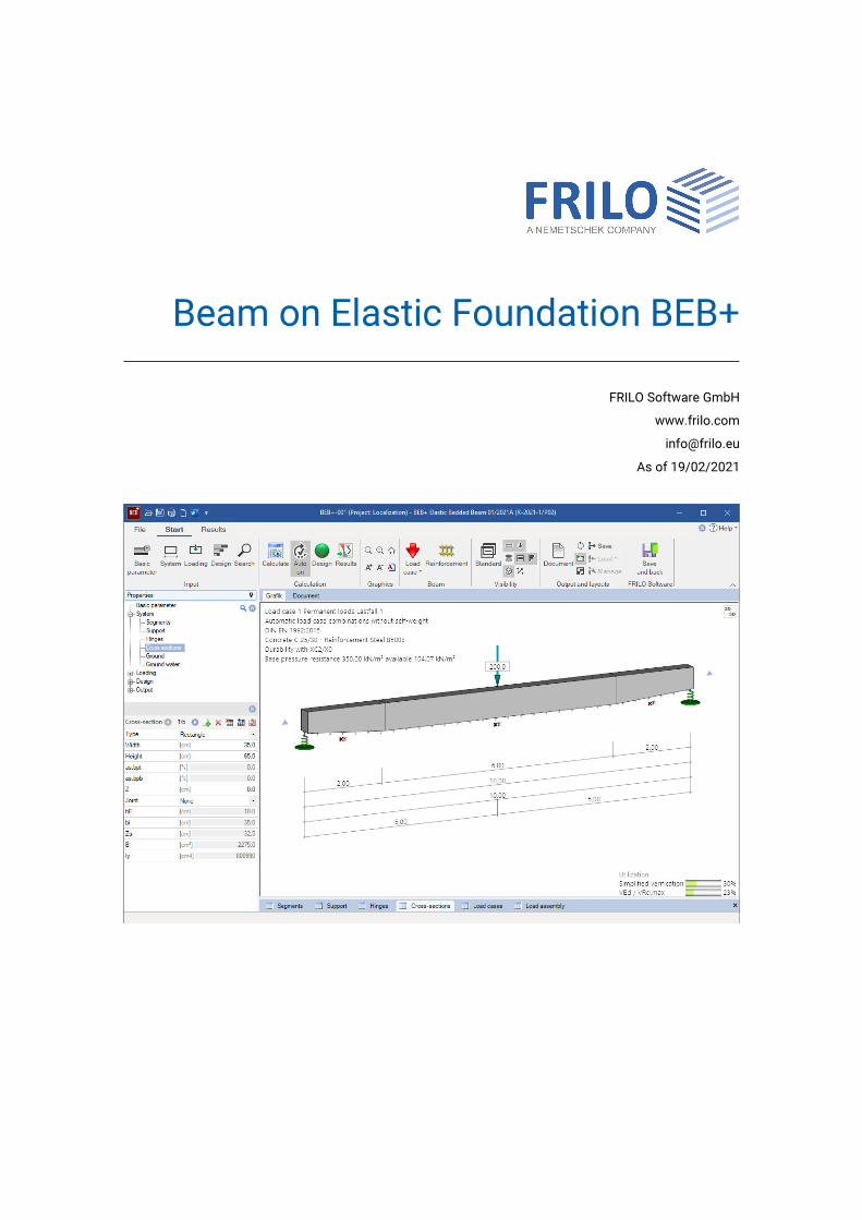
Beam on Elastic Foundation BEB+
FRILO Software GmbH
www.frilo.com
As of 19/02/2021

Beam on Elastic Foundation - BEB+
Contents
Application options 3
Basis of calculation 4
Basic parameters 5
System 6
Segments 7
Supports 7
Hinges 8
Cross-sections 9
Ground 10
Loading 11
Load cases 11
Loads 12
Load case combinations 13
Moving loads 14
Design 15
Output 17
Results / additional buttons 17
Reinforcement dialog 18
Reference literature 20
Basic Documentation – Overview
In addition to the individual program manuals, you will find basic explanations on the operation of the programs on our homepage www.frilo.com SupportArticles/InformationBasic operating instructions.

BEB+
FRILO Software GmbH Page 3
Application options
The BEB+ application is suitable for the calculation of elastically supported beams and one-way slabs in accordance with the subgrade reaction modulus method.
You can optionally select whether foundations and stiffness should be constant, linear or erratic.
You can set the foundation to zero, either completely or in individual sections.
If you set the foundation to zero over the total beam, at least two supports are required. You can add further rigid or elastic supports.
Loading
Uniformly distributed loads (UDL)
Concentrated loads
Concentrated moments
Trapezoidal loads
In addition to this, you can calculate moving loads based on concentrated loads.
Joints
Bending joints can be defined at freely selectable points.
Cross-sections / Cross-sectional Jumps
Rectangular cross-section
T-beam with a slab on top and/or on bottom
You can divide the beam into individual segments with a cross-section at the beginning and one at the end of each beam segment.
Results / Design
Internal forces
Displacements
Design
Concrete stresses
Reinforcing steel stress
Crack width
Optional: Shear design for a slab The ‘Shear design of slab’ option is available to ensure a correct slab shear design for strips cut out of a slab even if the cross-section to be designed is that of a beam.
Available standards
DIN EN 1992
BS EN 1992
ÖNORM EN 1992
EN 1992
In addition, still DIN 1045 07-88 / DIN 1045-1 / DIN 1045-1/2008/ ÖNorm B4700
Beam on elastic foundation
Page 4 Innovative solutions for structural analysis and design
Basis of calculation
The calculation is based on the subgrade reaction modulus method and the displacement method.
A linear elastic behaviour of the soil is assumed, i.e. the subsidence at each point of the beam is proportional to the soil pressure at this point. The proportionality factor is the subgrade modulus (also: foundation modulus). It can be interpreted as a spring constant. The software can consider compression springs and tension springs. Because a tension spring does not comply with the actual soil behaviour, no foundation modulus should be specified for beam areas where the foundation is loaded by tension.
The total stiffness of the system is obtained by assembling the element stiffnesses of the individual beam segments and of the foundation.
The system unknowns in the set of equations are the displacements and translations at the nodes. The internal forces and the soil pressure are calculated from these entities.
Subgrade reaction modulus
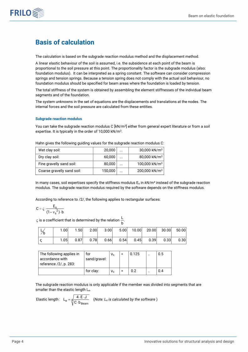
You can take the subgrade reaction modulus C [kN/m3] either from general expert literature or from a soil expertise. It is typically in the order of 10,000 kN/m3.
Hahn gives the following guiding values for the subgrade reaction modulus C:
Wet clay soil: 20,000 ... 30,000 kN/m3
Dry clay soil: 60,000 ... 80,000 kN/m3
Fine gravelly sand soil: 80,000 ... 100,000 kN/m3
Coarse gravelly sand soil: 150,000 ... 200,000 kN/m3
In many cases, soil expertises specify the stiffness modulus Es in kN/m² instead of the subgrade reaction modulus. The subgrade reaction modulus required by the software depends on the stiffness modulus.
According to reference to /2/, the following applies to rectangular surfaces:
s
2
s
EC
(1 ) b
L is a coefficient that is determined by the relation .
b
= V ◊- n ◊
V
Lb
1.00 1.50 2.00 3.00 5.00 10.00 20.00 30.00 50.00
ς 1.05 0.87 0.78 0.66 0.54 0.45 0.39 0.33 0.30
The following applies in accordance with reference /2/, p. 283:
for sand/gravel:
νs = 0.125 .. 0.5
for clay: νs = 0.2 .. 0.4
The subgrade reaction modulus is only applicable if the member was divided into segments that are smaller than the elastic length Le.
4e
Beam
4 E JElastic length : L
C b
◊ ◊
=
◊
(Note: Le is calculated by the software )
BEB+
FRILO Software GmbH Page 5
Basic parameters
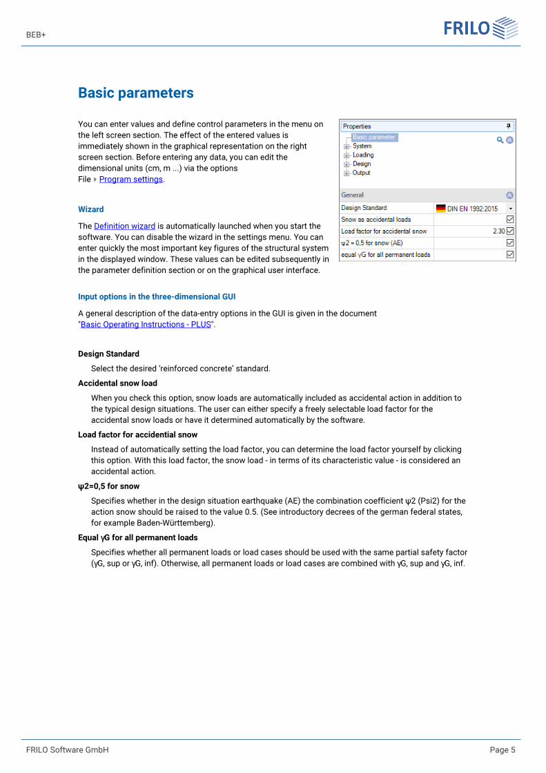
You can enter values and define control parameters in the menu on the left screen section. The effect of the entered values is immediately shown in the graphical representation on the right screen section. Before entering any data, you can edit the dimensional units (cm, m ...) via the options FileProgram settings.
Wizard
The Definition wizard is automatically launched when you start the software. You can disable the wizard in the settings menu. You can enter quickly the most important key figures of the structural system in the displayed window. These values can be edited subsequently in the parameter definition section or on the graphical user interface.
Input options in the three-dimensional GUI
A general description of the data-entry options in the GUI is given in the document "Basic Operating Instructions - PLUS".
Design Standard
Select the desired ‘reinforced concrete’ standard.
Accidental snow load
When you check this option, snow loads are automatically included as accidental action in addition to the typical design situations. The user can either specify a freely selectable load factor for the accidental snow loads or have it determined automatically by the software.
Load factor for accidential snow
Instead of automatically setting the load factor, you can determine the load factor yourself by clicking this option. With this load factor, the snow load - in terms of its characteristic value - is considered an accidental action.
ψ2=0,5 for snow
Specifies whether in the design situation earthquake (AE) the combination coefficient ψ2 (Psi2) for the action snow should be raised to the value 0.5. (See introductory decrees of the german federal states, for example Baden-Württemberg).
Equal γG for all permanent loads
Specifies whether all permanent loads or load cases should be used with the same partial safety factor (γG, sup or γG, inf). Otherwise, all permanent loads or load cases are combined with γG, sup and γG, inf.

Beam on elastic foundation
Page 6 Innovative solutions for structural analysis and design
System
Concrete / Reinforcing steel
The selection options for the concrete quality and the reinforcing steel grade depend on the selected standard.
Beam length
Total length of the beam. Note: If you define several beam segments subsequently, the total
length specified here remains constant.
Remarks
Click on the button to enter your own comments on the system.
BEB+
FRILO Software GmbH Page 7
Segments
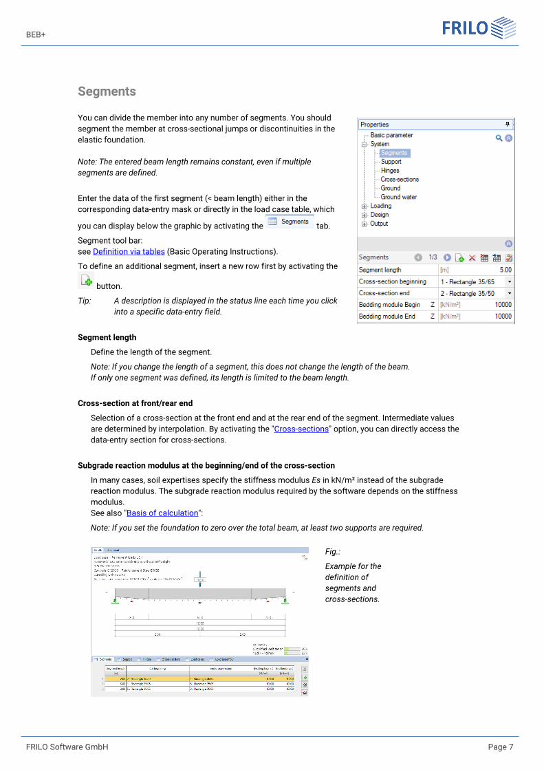
You can divide the member into any number of segments. You should segment the member at cross-sectional jumps or discontinuities in the elastic foundation. Note: The entered beam length remains constant, even if multiple
segments are defined.
Enter the data of the first segment (< beam length) either in the corresponding data-entry mask or directly in the load case table, which
you can display below the graphic by activating the tab.
Segment tool bar: see Definition via tables (Basic Operating Instructions).
To define an additional segment, insert a new row first by activating the
button.
Tip: A description is displayed in the status line each time you click
into a specific data-entry field.
Segment length
Define the length of the segment.
Note: If you change the length of a segment, this does not change the length of the beam.
If only one segment was defined, its length is limited to the beam length.
Cross-section at front/rear end
Selection of a cross-section at the front end and at the rear end of the segment. Intermediate values are determined by interpolation. By activating the "Cross-sections" option, you can directly access the data-entry section for cross-sections.
Subgrade reaction modulus at the beginning/end of the cross-section
In many cases, soil expertises specify the stiffness modulus Es in kN/m² instead of the subgrade reaction modulus. The subgrade reaction modulus required by the software depends on the stiffness modulus. See also "Basis of calculation":
Note: If you set the foundation to zero over the total beam, at least two supports are required.
Fig.:
Example for the
definition of
segments and
cross-sections.

Beam on elastic foundation
Page 8 Innovative solutions for structural analysis and design
Supports
Item
Distance to the front end of the beam.
Rigid
Check this option for a non-sway support in the z-direction.
Spring / Clamping
An elastic support is defined by specifying a corresponding spring stiffness.
The dimension of the spring stiffness is [force/length].
You can calculate the spring stiffness by applying a unit force to the load-bearing component. The spring stiffness results from the following equation:
unit forceC
deformation=
Hinges
Moment hinges are defined via the position of the hinge in relation to the beam front end.
Hinges at a distance a < beam height to the front end or rear end of the beam are not recommended.

BEB+
FRILO Software GmbH Page 9
Cross-sections
Type Rectangle
T-beam with a slab on top and/or on bottom
Plate width on top/on bottom
See graph: bpt or bpb. The slab width must always exceed the web width by at least 4 cm.
Plate thickness
See graph: dpt or dpb.
Width / Height
See graph: bpt or dpb.
as,bpt / as,bpb
Define the amount of the bending reinforcement that is not in the web area but in the plate area. This percentage is considered for the check of the lateral connection reinforcement of the T-bar.
Joint
Define whether this cross-section has an in-situ concrete supplement in which you adjust the roughness.
hE / bi
Height or width of the joint of the in-situ concrete supplement.
Fig.: Cross-section dimensions / designations
Beam on elastic foundation
Page 10 Innovative solutions for structural analysis and design
Ground
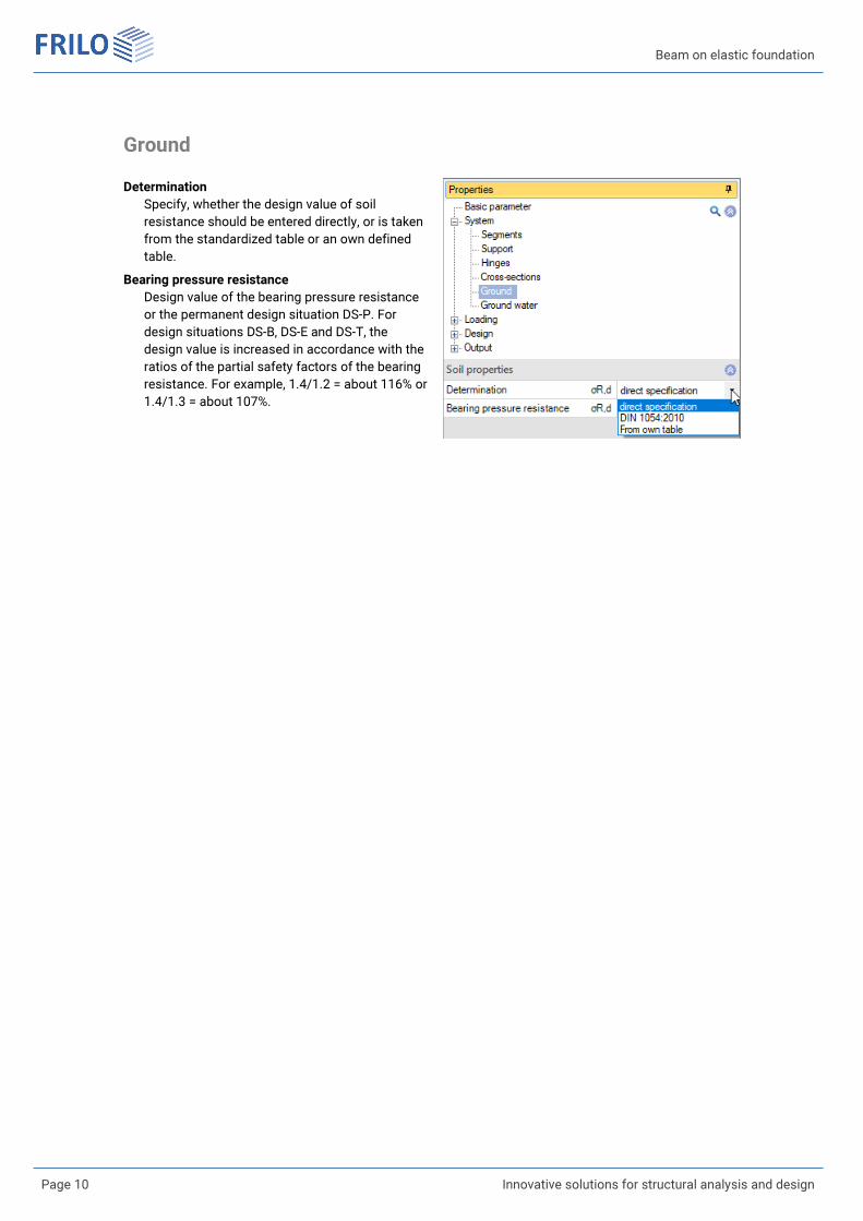
Determination
Specify, whether the design value of soil resistance should be entered directly, or is taken from the standardized table or an own defined table.
Bearing pressure resistance
Design value of the bearing pressure resistance or the permanent design situation DS-P. For design situations DS-B, DS-E and DS-T, the design value is increased in accordance with the ratios of the partial safety factors of the bearing resistance. For example, 1.4/1.2 = about 116% or 1.4/1.3 = about 107%.
BEB+
FRILO Software GmbH Page 11
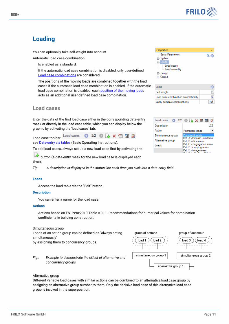
Loading
You can optionally take self-weight into account.
Automatic load case combination:
Is enabled as a standard.
If the automatic load case combination is disabled, only user-defined Load case combinations are considered.
The positions of the moving loads are combined together with the load cases if the automatic load case combination is enabled. If the automatic load case combination is disabled, each position of the moving loads acts as an additional user-defined load case combination.
Load cases
Enter the data of the first load case either in the corresponding data-entry mask or directly in the load case table, which you can display below the graphic by activating the 'load cases' tab.
Load case toolbar: see Data-entry via tables (Basic Operating Instructions).
To add load cases, always set up a new load case first by activating the
button (a data-entry mask for the new load case is displayed each time).
Tip: A description is displayed in the status line each time you click into a data-entry field.
Loads
Access the load table via the “Edit” button.
Description
You can enter a name for the load case.
Actions
Actions based on EN 1990:2010 Table A.1.1 - Recommendations for numerical values for combination coefficients in building construction.
Simultaneous group Loads of an action group can be defined as "always acting simultaneously" by assigning them to concurrency groups.
Fig.: Example to demonstrate the effect of alternative and
concurrency groups
Alternative group Different variable load cases with similar actions can be combined to an alternative load case group by assigning an alternative group number to them. Only the decisive load case of this alternative load case group is invoked in the superposition.
Beam on elastic foundation
Page 12 Innovative solutions for structural analysis and design
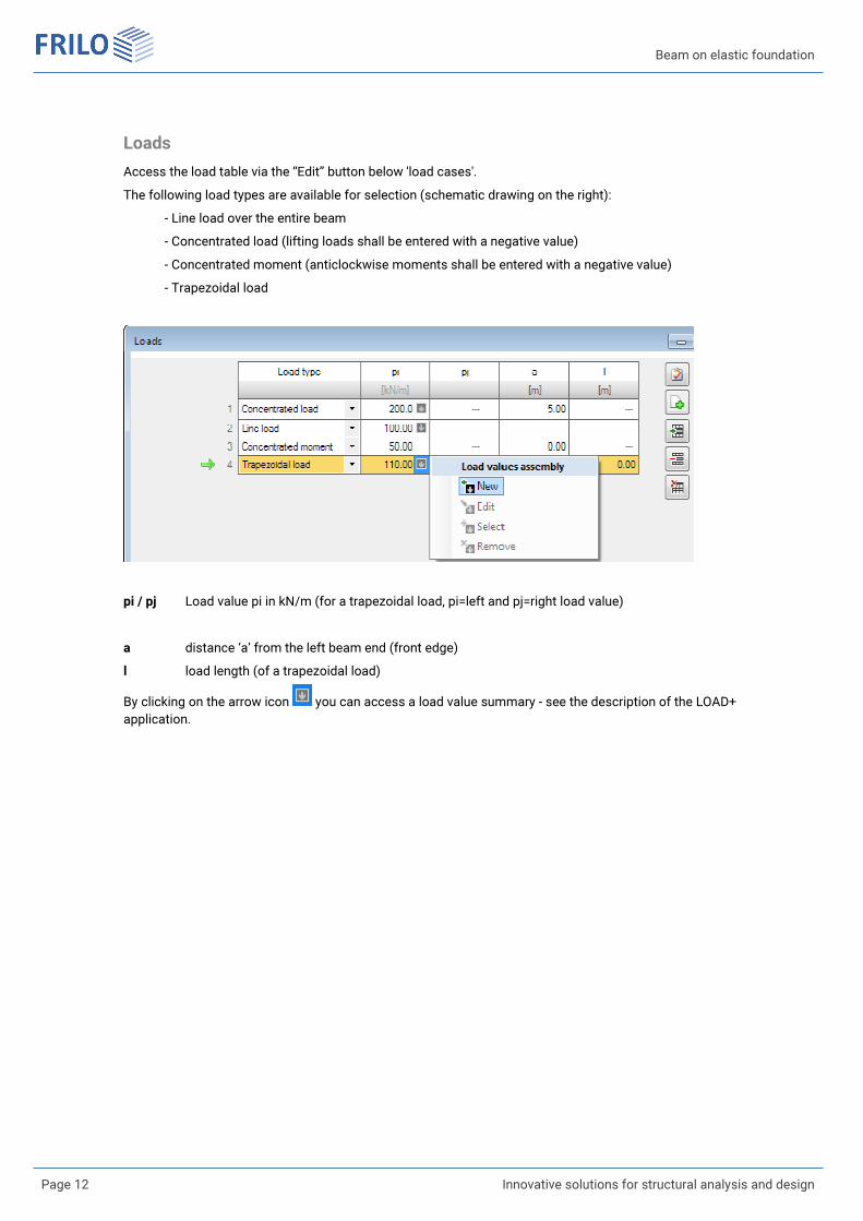
Loads
Access the load table via the “Edit” button below 'load cases'.
The following load types are available for selection (schematic drawing on the right):
- Line load over the entire beam
- Concentrated load (lifting loads shall be entered with a negative value)
- Concentrated moment (anticlockwise moments shall be entered with a negative value)
- Trapezoidal load
pi / pj Load value pi in kN/m (for a trapezoidal load, pi=left and pj=right load value)
a distance ‘a’ from the left beam end (front edge)
l load length (of a trapezoidal load)
By clicking on the arrow icon you can access a load value summary - see the description of the LOAD+ application.
BEB+
FRILO Software GmbH Page 13
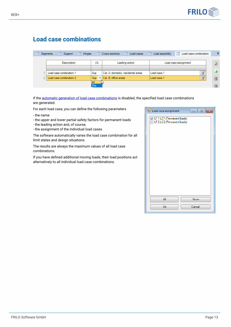
Load case combinations
If the automatic generation of load case combinations is disabled, the specified load case combinations are generated.
For each load case, you can define the following parameters
- the name - the upper and lower partial safety factors for permanent loads - the leading action and, of course, - the assignment of the individual load cases
The software automatically varies the load case combination for all limit states and design situations.
The results are always the maximum values of all load case combinations.
If you have defined additional moving loads, their load positions act alternatively to all individual load case combinations.
Beam on elastic foundation
Page 14 Innovative solutions for structural analysis and design
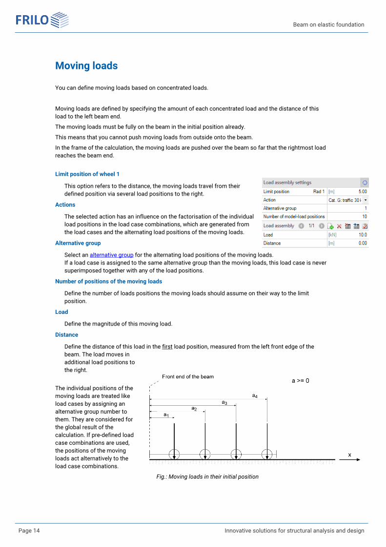
Moving loads
You can define moving loads based on concentrated loads.
Moving loads are defined by specifying the amount of each concentrated load and the distance of this load to the left beam end.
The moving loads must be fully on the beam in the initial position already.
This means that you cannot push moving loads from outside onto the beam.
In the frame of the calculation, the moving loads are pushed over the beam so far that the rightmost load reaches the beam end.
Limit position of wheel 1
This option refers to the distance, the moving loads travel from their defined position via several load positions to the right.
Actions
The selected action has an influence on the factorisation of the individual load positions in the load case combinations, which are generated from the load cases and the alternating load positions of the moving loads.
Alternative group
Select an alternative group for the alternating load positions of the moving loads. If a load case is assigned to the same alternative group than the moving loads, this load case is never superimposed together with any of the load positions.
Number of positions of the moving loads
Define the number of loads positions the moving loads should assume on their way to the limit position.
Load
Define the magnitude of this moving load.
Distance
Define the distance of this load in the first load position, measured from the left front edge of the beam. The load moves in additional load positions to the right.
The individual positions of the moving loads are treated like load cases by assigning an alternative group number to them. They are considered for the global result of the calculation. If pre-defined load case combinations are used, the positions of the moving loads act alternatively to the load case combinations.
Fig.: Moving loads in their initial position
BEB+
FRILO Software GmbH Page 15
Design
Settings
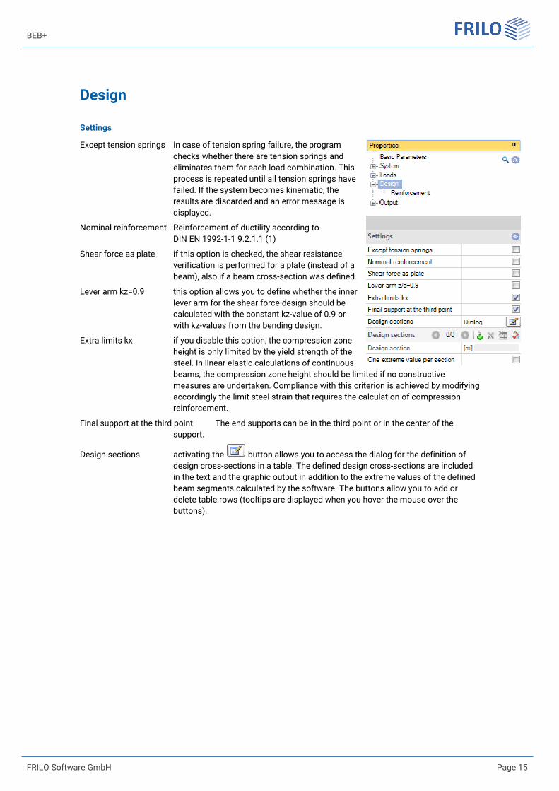
Except tension springs In case of tension spring failure, the program checks whether there are tension springs and eliminates them for each load combination. This process is repeated until all tension springs have failed. If the system becomes kinematic, the results are discarded and an error message is displayed.
Nominal reinforcement Reinforcement of ductility according to DIN EN 1992-1-1 9.2.1.1 (1)
Shear force as plate if this option is checked, the shear resistance verification is performed for a plate (instead of a beam), also if a beam cross-section was defined.
Lever arm kz=0.9 this option allows you to define whether the inner lever arm for the shear force design should be calculated with the constant kz-value of 0.9 or with kz-values from the bending design.
Extra limits kx if you disable this option, the compression zone height is only limited by the yield strength of the steel. In linear elastic calculations of continuous beams, the compression zone height should be limited if no constructive measures are undertaken. Compliance with this criterion is achieved by modifying accordingly the limit steel strain that requires the calculation of compression reinforcement.
Final support at the third point The end supports can be in the third point or in the center of the support.
Design sections activating the button allows you to access the dialog for the definition of design cross-sections in a table. The defined design cross-sections are included in the text and the graphic output in addition to the extreme values of the defined beam segments calculated by the software. The buttons allow you to add or delete table rows (tooltips are displayed when you hover the mouse over the buttons).

Beam on elastic foundation
Page 16 Innovative solutions for structural analysis and design
Reinforcement
Concrete covering The concrete cover refers to the lateral force reinforcement enclosing the bending reinforcement and has an influence on the transverse force design.
Reinforcement layer Center of gravity of the reinforcement.
Minimal diameter Defines a minimum diameter used in the calculation of the concrete cover and the center of gravity of the reinforcement from which starts the calculation of reinforcement in the reinforcement dialog.
Durability activating the button displays the Durability dialog. When you confirm your settings in this dialog with OK, the concrete cover, reinforcement layers and their diameter are checked and adjusted accordingly.
Creep factor ψ accesses the dialog for the creep factor and the shrinkage strain.
BEB+
FRILO Software GmbH Page 17
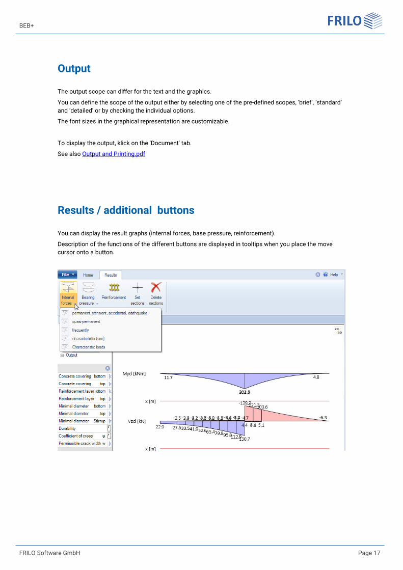
Output
The output scope can differ for the text and the graphics.
You can define the scope of the output either by selecting one of the pre-defined scopes, ‘brief’, ‘standard’ and ‘detailed’ or by checking the individual options.
The font sizes in the graphical representation are customizable.
To display the output, klick on the 'Document' tab.
See also Output and Printing.pdf
Results / additional buttons
You can display the result graphs (internal forces, base pressure, reinforcement).
Description of the functions of the different buttons are displayed in tooltips when you place the move cursor onto a button.
Beam on elastic foundation
Page 18 Innovative solutions for structural analysis and design
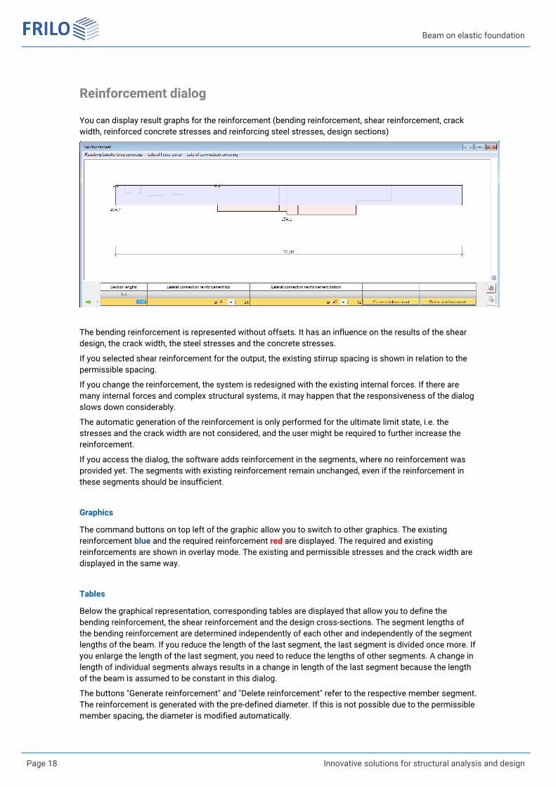
Reinforcement dialog
You can display result graphs for the reinforcement (bending reinforcement, shear reinforcement, crack width, reinforced concrete stresses and reinforcing steel stresses, design sections)
The bending reinforcement is represented without offsets. It has an influence on the results of the shear design, the crack width, the steel stresses and the concrete stresses.
If you selected shear reinforcement for the output, the existing stirrup spacing is shown in relation to the permissible spacing.
If you change the reinforcement, the system is redesigned with the existing internal forces. If there are many internal forces and complex structural systems, it may happen that the responsiveness of the dialog slows down considerably.
The automatic generation of the reinforcement is only performed for the ultimate limit state, i.e. the stresses and the crack width are not considered, and the user might be required to further increase the reinforcement.
If you access the dialog, the software adds reinforcement in the segments, where no reinforcement was provided yet. The segments with existing reinforcement remain unchanged, even if the reinforcement in these segments should be insufficient.
Graphics
The command buttons on top left of the graphic allow you to switch to other graphics. The existing reinforcement blue and the required reinforcement red are displayed. The required and existing reinforcements are shown in overlay mode. The existing and permissible stresses and the crack width are displayed in the same way.
Tables
Below the graphical representation, corresponding tables are displayed that allow you to define the bending reinforcement, the shear reinforcement and the design cross-sections. The segment lengths of the bending reinforcement are determined independently of each other and independently of the segment lengths of the beam. If you reduce the length of the last segment, the last segment is divided once more. If you enlarge the length of the last segment, you need to reduce the lengths of other segments. A change in length of individual segments always results in a change in length of the last segment because the length of the beam is assumed to be constant in this dialog.
The buttons "Generate reinforcement" and "Delete reinforcement" refer to the respective member segment. The reinforcement is generated with the pre-defined diameter. If this is not possible due to the permissible member spacing, the diameter is modified automatically.

BEB+
FRILO Software GmbH Page 19
Edit the entire reinforcement
There are two command buttons on top right of the graphic, 'Generate complete reinforcement' and 'Delete complete reinforcement'. These buttons refer to the entire bending and shear reinforcement, independent of the graphic or table currently displayed.
Cancel
If you exit the dialog by activating the 'Cancel' button, the previous condition of the reinforcement is re-established, and the beam is re-designed with the calculated internal forces.
Beam on elastic foundation
Page 20 Innovative solutions for structural analysis and design
Reference literature
/1/ Beton-Kalender 1980, Part II, page 592.
/2/ Hahn, J.: Durchlaufträger, Rahmen, Platten und Balken auf elastischer Bettung. (Werner) Düsseldorf 1970