Hopping robot based on free vibration of an elastic curved beam
6
2011 IEEElASME International Conference on Advanced Intelligent Mechatronics (AIM2011) Budapest, Hungary, July 3-7, 2011 Hopping Robot Based on Free Vibration of an Elastic Curved Beam Murat Reis and Fumiya Iida Absact- This study presents a novel approach to the design of low-cost and energy-efficient hopping robots, which makes use of free vibration of an elastic curved beam. We found that a hopping robot could benefit from an elastic curved beam in many ways such as low manufacturing cost, light body weight and small energy dissipation in mechanical interactions. A challenging problem of this design strategy, however, lies in harnessing the mechanical dynamics of free vibration in the elastic curved beam: because the free vibration is the outcome of coupled mechanical dynamics between actuation and mechanical structures, it is not trivial to systematically design mechanical structures and control architectures for stable locomotion. From this perspective, this paper investigates a case study of simple hopping robot identify the design principles of mechanics and control. We developed a hopping robot consisting of an elastic curved beam and a small rotating mass, which was then modeled and analyzed in simulation. The experimental results show that the robot is capable of exhibiting stable hopping gait patterns by using a small actuation with no sensory feedback owing to the intrinsic stability of coupled mechanical dynamics. Furthermore, an additional analysis shows that, by exploiting free vibration of the elastic curved beam, cost of transport of the proposed hopping locomotion can be in the same rage of animals' locomotion including human running. I. INTRODUCTION Development of low-cost and energy-efficient locomotion robots has been one of the long-standing challenges in robotics research. While energy-efficient robot locomotion was mainly investigated in human-like bipedal walking in the past [1], hopping and running gaits are also a highly interesting challenge for the locomotion at a larger velocity, in particular. Inspired om the biological studies on the en- ergetics of animal locomotion (e.g.[2], [3], [4]), a number of robotics researchers explored energetically efficient hopping and running robots in the past. Although the majority is still centered around the theoretical investigations of simulated legged robots equipped with idealized springs (e.g.[5], [6], [7], [8], [9]), there have been a few successful attempts in the past, in which energetically efficient hopping robots were demonstrated [11], [12]. Generally speaking, it is still a highly challenging problem to reduce the efforts of motor control (e.g. by exploiting "self-stability" of mechanical This study was supported by the Scientific and Technological Research Council of Turkey TUBITAK and Swiss National Science Foundation Grant No. PPOOP2123387/ 1. M. Reis is with the Uludag University, 16059 Bursa, Turkey and Bio-Inspired Robotics Lab, Institute of Robotics and Intelligent Systems at ETH Zurich, Leonhardstr. 27, 8092 Zurich, Switzerland; F Iida is with Bio-Inspired Robotics Lab, Institute of Robotics and Intelligent Sys- tems at ETH Zurich, Switzerland. [fumiya.iida, murat.reis 1 @mavt.ethz.ch 978-1-4577-0839-8/11/$26.00 ©2011 IEEE dynamics) while minimizing the energy dissipation in me- chanical interactions with the environment [10], [13]. Toward a significant breakthrough in this research domain, this paper proposes a novel approach to the design of hopping robots that makes use of ee vibration of an elastic curved beam. We found that a hopping robot could benefit from an elastic curved beam in many ways: first, a curved beam can be generally very light weight and low damping which are necessary for energy-efficient hopping locomotion; second, material and manufacturing cost of an elastic curved beam can be substantially lower than those of segmented body structures with many mechanical components (such as pin- joints, bearings, bolts and nuts); and third, ee vibration of an elastic curved beam can be induced by substantially small power of actuation when operated at a resonance frequency. Despite these favorable advantages, the challenge of this design strategy lies in harnessing mechanical dynamics of free vibration in the elastic curved beam. More specifically, while designing mechanical structures and control architec- tures, we have to consider coupled mechanical dynamics of the curved beam and actuators, as well as dynamics of the ground interactions and the aerial phase, for example. From this perspective, the main goal of this paper is to systematically explore this design strategy of hopping robots through a minimalistic case study. We developed a simple hopping robot consisting of an elastic curved beam and a small rotating mass, and the robot was modeled and analyzed in simulation. We structured this paper as follows. First, in Section II, we introduce the overall design and control strategy of a hopping robot we developed, and explain the physics model investigated in this paper. In Section III, a system identification process is conducted to verify the feasibility of the mode. And finally, in Section IV, we analyze the hopping locomotion of the proposed model and discuss stability and energy efficiency. 892 II. MODELING OF HOPPING DYNAMICS The mechanical structure of hopping robot can be decom- posed into an elastic curved beam made of steel, a light- weight rigid aluminum foot, and an actuator module that contains a DC motor, gear box (gear reduction of 114.7:1), and a pair of symmetric rotating masses (Fig. l(a) and Fig.1(b)). An important design parameter was the curvature of the elastic beam, which was designed through a heuristic optimization process such that the robot could exhibit large hopping heights. When the DC motor is activated at approx- imately 6.8 Volt, the robot typically shows a stable hopping
-
Upload
independent -
Category
Documents
-
view
0 -
download
0
Transcript of Hopping robot based on free vibration of an elastic curved beam
2011 IEEElASME International Conference on Advanced Intelligent Mechatronics (AIM2011) Budapest, Hungary, July 3-7, 2011
Hopping Robot Based on Free Vibration of an Elastic Curved Beam
Murat Reis and Fumiya Iida
Abstract- This study presents a novel approach to the design of low-cost and energy-efficient hopping robots, which makes use of free vibration of an elastic curved beam. We found that a hopping robot could benefit from an elastic curved beam in many ways such as low manufacturing cost, light body weight and small energy dissipation in mechanical interactions. A challenging problem of this design strategy, however, lies in harnessing the mechanical dynamics of free vibration in the elastic curved beam: because the free vibration is the outcome of coupled mechanical dynamics between actuation and mechanical structures, it is not trivial to systematically design mechanical structures and control architectures for stable locomotion. From this perspective, this paper investigates a case study of simple hopping robot to identify the design principles of mechanics and control. We developed a hopping robot consisting of an elastic curved beam and a small rotating mass, which was then modeled and analyzed in simulation. The experimental results show that the robot is capable of exhibiting stable hopping gait patterns by using a small actuation with no sensory feedback owing to the intrinsic stability of coupled mechanical dynamics. Furthermore, an additional analysis shows that, by exploiting free vibration of the elastic curved beam, cost of transport of the proposed hopping locomotion can be in the same rage of animals' locomotion including human running.
I. INTRODUCTION
Development of low-cost and energy-efficient locomotion robots has been one of the long-standing challenges in robotics research. While energy-efficient robot locomotion was mainly investigated in human-like bipedal walking in the past [1], hopping and running gaits are also a highly interesting challenge for the locomotion at a larger velocity, in particular. Inspired from the biological studies on the energetics of animal locomotion (e.g.[2], [3], [4]), a number of robotics researchers explored energetically efficient hopping and running robots in the past. Although the majority is still centered around the theoretical investigations of simulated legged robots equipped with idealized springs (e.g.[5], [6], [7], [8], [9]), there have been a few successful attempts in the past, in which energetically efficient hopping robots were demonstrated [11], [12]. Generally speaking, it is still a highly challenging problem to reduce the efforts of motor control (e.g. by exploiting "self-stability" of mechanical
This study was supported by the Scientific and Technological Research Council of Turkey TUBITAK and Swiss National Science Foundation Grant No. PPOOP2123387/ 1.
M. Reis is with the Uludag University, 16059 Bursa, Turkey and Bio-Inspired Robotics Lab, Institute of Robotics and Intelligent Systems at ETH Zurich, Leonhardstr. 27, 8092 Zurich, Switzerland; F. Iida is with Bio-Inspired Robotics Lab, Institute of Robotics and Intelligent Systems at ETH Zurich, Switzerland. [fumiya. iida, murat. reis 1 @mavt.ethz.ch
978-1-4577-0839-8/11/$26.00 ©2011 IEEE
dynamics) while minimizing the energy dissipation in mechanical interactions with the environment [10], [13].
Toward a significant breakthrough in this research domain, this paper proposes a novel approach to the design of hopping robots that makes use of free vibration of an elastic curved beam. We found that a hopping robot could benefit from an elastic curved beam in many ways: first, a curved beam can be generally very light weight and low damping which are necessary for energy-efficient hopping locomotion; second, material and manufacturing cost of an elastic curved beam can be substantially lower than those of segmented body structures with many mechanical components (such as pinjoints, bearings, bolts and nuts); and third, free vibration of an elastic curved beam can be induced by substantially small power of actuation when operated at a resonance frequency.
Despite these favorable advantages, the challenge of this design strategy lies in harnessing mechanical dynamics of free vibration in the elastic curved beam. More specifically, while designing mechanical structures and control architectures, we have to consider coupled mechanical dynamics of the curved beam and actuators, as well as dynamics of the ground interactions and the aerial phase, for example. From this perspective, the main goal of this paper is to systematically explore this design strategy of hopping robots through a minimalistic case study. We developed a simple hopping robot consisting of an elastic curved beam and a small rotating mass, and the robot was modeled and analyzed in simulation.
We structured this paper as follows. First, in Section II, we introduce the overall design and control strategy of a hopping robot we developed, and explain the physics model investigated in this paper. In Section III, a system identification process is conducted to verify the feasibility of the mode. And finally, in Section IV, we analyze the hopping locomotion of the proposed model and discuss stability and energy efficiency.
892
II. MODELING OF HOPPING DYNAMICS
The mechanical structure of hopping robot can be decomposed into an elastic curved beam made of steel, a lightweight rigid aluminum foot, and an actuator module that contains a DC motor, gear box (gear reduction of 114.7:1), and a pair of symmetric rotating masses (Fig. l(a) and Fig. 1 (b)). An important design parameter was the curvature of the elastic beam, which was designed through a heuristic optimization process such that the robot could exhibit large hopping heights. When the DC motor is activated at approximately 6.8 Volt, the robot typically shows a stable hopping

rotating mass. m
(a) (b)
(c)
9
(a) (b)
Fig. 2. Free-body diagrams of the two masses. (a) Force vectors acting on the point mass A shown in Fig. l(b), and (b) those of the point mass B.
decomposed into two phases (i.e. stance and flight phases), and during the stance phase, the robot has no slippage on the ground. Two parameters YA and YA are used to switch between stance and flight phases. In the simulation, a stance phase is turned to a flight phase when YA = 0 and YA > O. And the next stance phase starts when YA = 0 and YA < O.
The rotating mass of the robot is modeled as a force vector determined by a small mass m, its rotation radius R, and angular velocity roo Therefore the force vector [Fx, Fy 1 can be assumed to be a sinusoidal oscillation of centripetal force:
FAt) = Acos/3, Fy(t) = Asin/3 -mg (I)
Fig. I. The hopping robot and its physics model. (a) A photograph of the where real-world robot which shows two red-colored LEOs for visual tracking of motion. (b) a schematic illustration of the robot indicating the two main masses, labeled A and S, as well as a small rotating mass, m. And (c) a physics model that is investigated in this paper.
locomotion pattern after a few cycles I . Based on the real-world experiments, we developed a
physics model of this robot, which resulted in the model with two point-masses, a linear spring, and a sinusoidal actuation force as shown in Fig. I(c). This model has five mechanical design parameters (i.e. B , kL , mA, mB, and £0), three control parameters (i.e. ro, /3o, and A), and ten state variables (YA, YB, XA, XB, /3, and velocities of those) as shown in Appendix. Note that we considered the following four assumptions in this modeling process: (a) the actuator module and foot are defined as two point masses, (b) the curved beam has no mass and no damping, and its spring constant can be determined by the material properties and the shape of the curved beam, (c) the curved beam is assumed to move in only one direction specified by B and no rotation is possible. As shown in this paper, this surprisingly simple model can represent the complex nature of the elastic curved beam in the steady state hopping behavior. d) The hopping behavior can be
I See the hopping demonstration video at http://www.birl.ethz.chlRobots/CurvedJ3eam-Hopper
893
A = mRro2, /3 = rot + f30 (2)
The mechanical dynamics of the robot can be decomposed into two main parts, as shown in Fig. 2. First, from Fig. 2(a), the equations of the motion for the foot mass mA can be described as
�)r,(Fx) A = mAxA (3)
FkcosB -Fs+NBsinB = mAxA (4)
+tr,(FY) A = mAYA (5)
NA -mAg+FksinB -NBcosB = mAYA (6)
And from Fig. 2(b), the equations of motion of the body mass mB can be derived as
�r,(Fx) B = mBxB (7)
-FkcosB -N BsinB + Fx = mBxB (8)
+tr,(FY) B = mBYB (9)
N BcosB -mBg -FksinB + Fy = mBY B (10)
Considering the kinematic relation between foot mass mA and body mass mB, we obtain the following constraint:
.. .. +Ys-YA
XB=XA --Btan (II)
During the stance phase, there is no motion in the foot mass mA, therefore:
(12)
Substituting these conditions to the equations of motion Eqs. (4), (6), (8) and (10), we obtain only one equation during the stance phase as follows:
kL ( . )
Fy . 2 YB - Lasm8-YB+YA +-' sm 8 mB mB
F, +�sin8cos8 -gsin28 (13)
mB In the flight phase, there is no ground reaction force (i.e.
NA = 0). and by substituting this condition to Eq. (6), we obtain the following three equations:
cos8 ( mB ) (.. .. )
Fx XA -- YA -YB + (14)
sin8 mA +mB mA +mB kL(Losin8 -YB + YA) +xAmBcos8sin8
YA mASin28 + mBcos28
YBmBcos28 -Fxcos8sin8 -gmASin28 + (1S)
mA sin2 8 + mBcos2 8 kL
( . ) Fy • 2 YB - Losm8-YB+YA +-' sm 8
mB mB F,
+�sin8cos8 +YAcos28 mB
-xASin8cos8 -gsin28 (16)
In the numerical simulation shown later in this paper, we employ an ODE solver of Matlab (ode4S). The switching between stance and flight phases is conducted in a following manner. In every simulation step during a stance phase, the ground reaction force on the foot mass NA is computed, and when it becomes negative, the flight phase starts. In a flight phase, every simulation step computes the vertical position and velocity of the foot mass YA and YA, and the flight phase ends with the two conditions, i.e. YA crosses zero when YA is negative.
III. SYSTEM IDENTIFICATION OF THE ROBOT
One of the main challenges of this paper is to estimate the spring constant kL of curved beam because all other mechanical design parameters can be statically measured. Although there are some previous investigations on vibration of the cylindrically curved [14] and slightly curved beams [IS], it is not trivial to analytically derive the eigen-values of strongly curved beams. Therefore, in this section, we experimentally obtain the spring constant kL of proposed model by using the real-world robot platform.
In the following system identification process, we assume that the spring constant kL can be estimated from the natural frequency of the robot body fixed on the ground. More specifically, we first activated the rotating mass of the robot fixed on the ground to induce a large perturbation and obtained the natural frequency oh of the system. And second, we estimate the spring constant kL from the natural frequency WL by using the following equation:
(17)
894
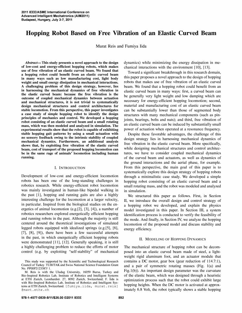
(a) (b)
Fig. 3. Rotational and radial free vibration of the elastic curved beam. The foot of robot is fixed on the ground and observed the free vibration of the robot body by observing the LED on top of the robot. (a) Rotational vibration of the curved beam, which was induced by the period and angular velocity of the rotating mass, To = 0.8 (s) and Wo = 2.51r (rad/s), respectively. (b) Radial vibration of the curved beam at To = 0.2 (s) and Wo = \01r (rad/s).
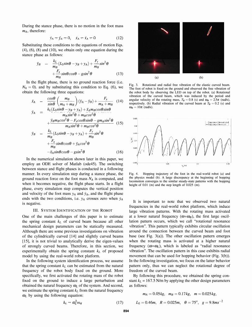
-O.OO5oi\----------.0.0:.., -------i!0 .• , ------.,,;0. '.-"
Fig. 4. Hopping trajectory of the foot in the real-world robot (a) and the physics model (b). A large discrepancy at the beginning of hopping locomotion converges to the similar steady-state patterns with the hopping height of 0.01 (m) and the step length of 0.025 (m).
It is important to note that we observed two natural frequencies in the real-world robot platform, which induce large vibration patterns. With the rotating mass activated at a lower natural frequency (w=we), the first large oscillation pattern occurs, which we call "rotational resonance vibration". This pattern typically exhibits circular oscillation around the connection between the curved beam and foot base (see Fig. 3(a)). The other oscillation pattern emerges when the rotating mass is activated at a higher natural frequency (w=wd, which is labeled as "radial resonance vibration". The oscillation pattern in this case exhibits radial movement that can be used for hopping behavior (Fig. 3(b)). In the following investigation, we focus on the latter behavior pattern only, thus we can neglect the rotational degree of freedom of the curved beam.
By following this procedure, we obtained the spring constant kL = 167.S N/m by applying the other design parameters as follows:
mA = O.OSkg, mB = O.17kg, m = 0.02Skg,
La = 0.46m, R = 0.02Sm, 8 = 7So , g = 9.8ms�2
Vertical position of point A
Vertical position of point B 0.55
� f:-�---;:!-;:-----:----:,;-----:----;:!-;:-----! o QS 1 1.S 2 ZS 3 Vertical force
�>:� o 0.5 1 1.5 2 2.5 3
Total Mechanic Energy (L\-+ T T)
� :;�I • -: -: . -----11 0.70,:-------;;0';".5
---';-------:,7.5----,2;--------=27.5
---.J3 Time (Second)
(a)
Vertical position of point A
Vertical position of point B
� :�� : 1 0.35:-----;:!-;:-----:----:';-----:----;:!-;:-· ----!-o O.S 1 1.S 2 2.S 3
Vertical force
�> J� : I o 0.5 1.S 2 2.5
Total Mechanic Energy (L\-+TT)
� :� ' I o O.S 1 1.S 2 2.S 3
Time (Second)
(c)
Vertical position of point A
Vertical force
0.5 '.5 2.5
Total Mechanic Energy (L\-+ T T)
� ::� : I o 0.5 1 1.5 2 2.5 3
Time (Second)
(b)
055 t _ r\ ' � �ert i:�:itiO� Of�Oin�B : I � 0:4:rv �'-V� V�V V,\
O .35L----:":c --�--�--�--�---.J o 0.5 1 1.5 2 2.5 3
Vertical force
�> :rNWl0JIM • I o 0.5 1.5 2.5 3
Total Mechanic Energy (L\-+ T T)
� :�"-----------:":��-----"---------: I o 0.5 1 1.5 2 2.5 3
Time (Second)
(d)
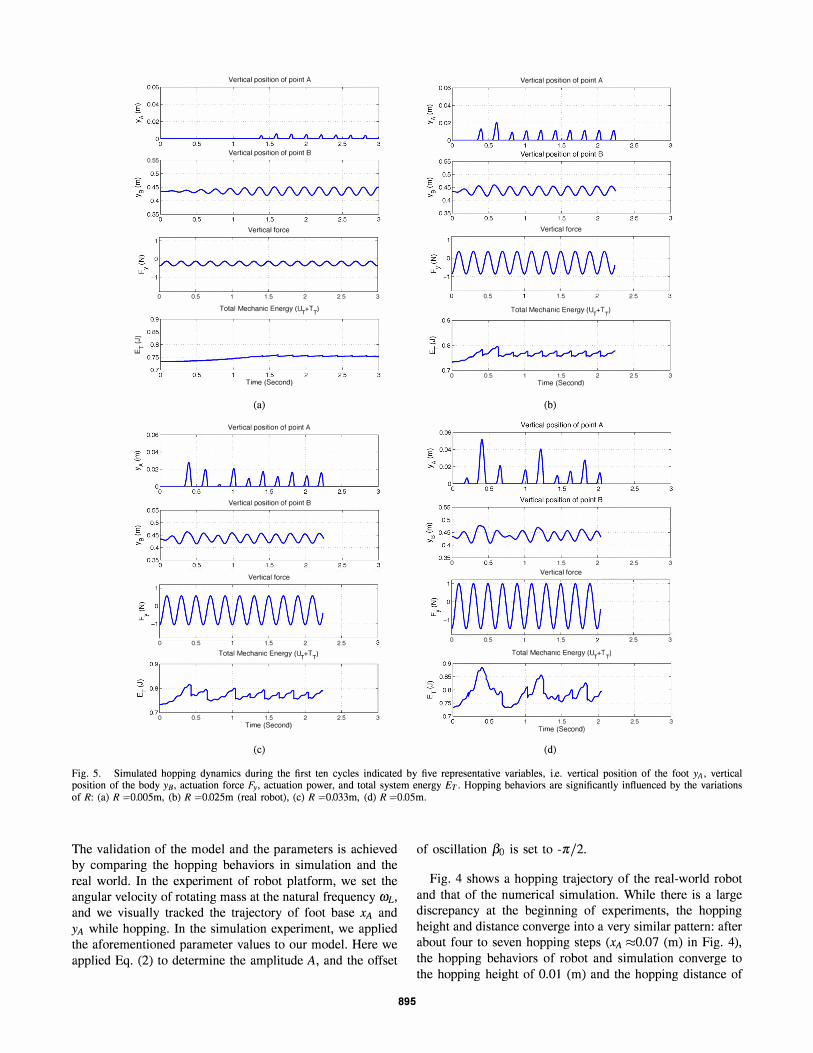
Fig. S. Simulated hopping dynamics during the first ten cycles indicated by five representative variables, i.e. vertical position of the foot YA, vertical position of the body YB, actuation force Fy, actuation power, and total system energy E1'. Hopping behaviors are significantly influenced by the variations of R: (a) R =O.OOSm, (b) R =O.02Sm (real robot), (c) R =O.033m, (d) R =O.OSm.
The validation of the model and the parameters is achieved by comparing the hopping behaviors in simulation and the real world. In the experiment of robot platform, we set the angular velocity of rotating mass at the natural frequency Q'JL, and we visually tracked the trajectory of foot base XA and
YA while hopping. In the simulation experiment, we applied the aforementioned parameter values to our model. Here we applied Eq. (2) to determine the amplitude A, and the offset
895
of oscillation f30 is set to -nI2.
Fig. 4 shows a hopping trajectory of the real-world robot and that of the numerical simulation. While there is a large discrepancy at the beginning of experiments, the hopping height and distance converge into a very similar pattern: after about four to seven hopping steps (XA ;:::::0.07 (m) in Fig. 4), the hopping behaviors of robot and simulation converge to the hopping height of 0.Ql (m) and the hopping distance of
0.025 (m). From this experimental result, we conclude that the model is able to characterize the steady state hopping behavior of the robot platform.
IV. STEADY STATE HOPPING EXPERIMENTS
As shown in the experiments of the previous section, the motor control parameters of hopping locomotion significantly rely on the mechanical design of the robot. Because the main driving force of hopping locomotion is the free vibration of the elastic curved beam, the rotating mass cannot be operated arbitrarily but needs to be at the natural frequency determined by the mechanical design. In this section, in order to complete the analysis of the coupled dynamics between mechanical design and motor control, we investigate the other open parameter of motor control which is the amplitude of rotating mass A in Eq. (2). The following experiments examine variations of the rotation radius R of the centripetal force (mRro2), and analyze the influence of this parameter to hopping locomotion.
A. Analysis of Hopping Dynamics
The first set of simulation experiments were conducted with four different values of rotation radius R, and Fig. 5 shows the first ten cycles of actuation starting from the same static initial condition. An important observation in this figure is that it requires no sensory feedback to achieve steady state locomotion in most of the cases. More specifically, in Fig. 5 (a-c), even though the motor control is fixed at a constant periodic oscillation (indicated by the periodic Fy in the figures), the perturbations of YB and YA converge into steady state periodic cycles after one or two seconds.
Another interesting characteristics is the starting time of hopping with respect to the rotation radius R. With R =
0.005m (Fig. 5(a)), for example, the hopping motion starts after approximately 7 cycles of oscillation at around 1.4 (s), whereas, with R = 0.033m (Fig. 5(b)), it starts after 2 cycles of motor oscillation at 0.4 (s). However, with an even larger value of rotation radius R, the hopping behavior does not converge to a steady state as shown in Fig. 5 (d). In this case, the oscillation of curved beam YB and rotating mass Fy are never synchronized, and as a result, it exhibits a chaotic hopping behavior.
It is also important to mention that the fluctuation of total mechanical energy during the hopping locomotion is maintained fairly low in the steady state locomotion. Namely, in Fig. 5 (a-c), the amplitude of fluctuation is within the range of approximately 0.05 (1), and the energy losses are kept small only at the ground impact.
B. Analysis of Energy Efficiency
The steady state hopping locomotion is further analyzed with respect to locomotion velocity and cost of transport. Here, we conducted additional simulation experiments with more variations of parameter R, and in each parameter value, we measured average velocity of transport (VoT) and cost of transport (CoT) of steady state locomotion over five steps (Fig. 6). From these figures, we can again clearly observe the
896
� � I-0 >
E
0.12
0.11
0.1
0.09
0.08
0.07
0.06
0.05
0.04
0.03 .
0.020•
...
.. ....
.. ...
. .
Stable Unstable
. . . . ••
•• >
.
•• Real Robot
.
.. . .. ._ e. . ..
.
..
0.005 0.01 0.015 0.02 0.025 0.03 0.035 0.04 0.045 0.05 R(m)
(a)
Stable Unstable ..
.•. . ....
. .
CoT offroglire hopping (45°) ••
� •••••••
5 --------------y-------------- -.-. �-----\------------- ----••
--
•••• Real Robot ..
. . . c> 4 "" . ..
I- 3 o .. .
..
U .
2 - - .- - - - - - -r-CoT of human running
1 •
%�� 0.� 00� 5--�0.0�1--70.�017 5--�0.0= 2--70.� 027 5--0�.0� 3 --�0.0�3� 5�0� .0�4--�0.0�4� 5�0.05 R(m)
(b)
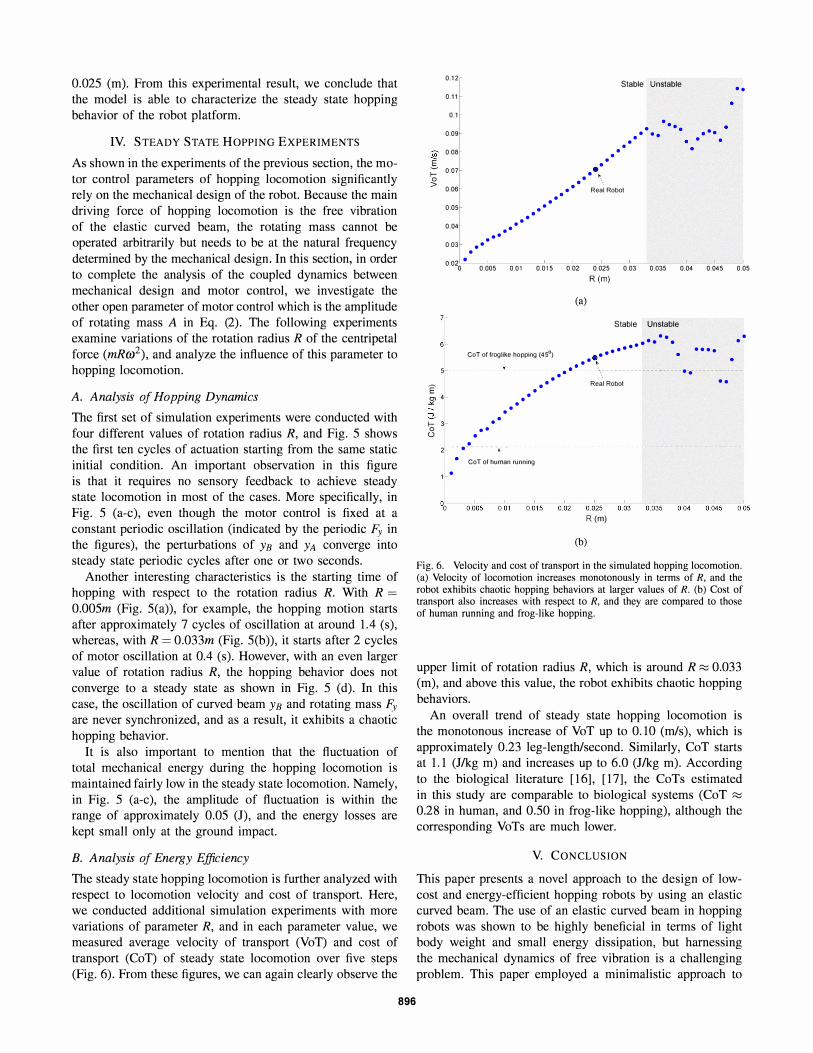
Fig. 6. Velocity and cost of transport in the simulated hopping locomotion. (a) Velocity of locomotion increases monotonously in terms of R. and the robot exhibits chaotic hopping behaviors at larger values of R. (b) Cost of transport also increases with respect to R. and they are compared to those of human running and frog-like hopping.
upper limit of rotation radius R, which is around R � 0.033 (m), and above this value, the robot exhibits chaotic hopping behaviors.
An overall trend of steady state hopping locomotion is the monotonous increase of VoT up to 0.10 (m/s), which is approximately 0.23 leg-length/second. Similarly, CoT starts at 1.1 (1/kg m) and increases up to 6.0 (J/kg m). According to the biological literature [16], [17], the CoTs estimated in this study are comparable to biological systems (CoT �
0.28 in human, and 0.50 in frog-like hopping), although the corresponding VoTs are much lower.
V. CONCLUSION
This paper presents a novel approach to the design of lowcost and energy-efficient hopping robots by using an elastic curved beam. The use of an elastic curved beam in hopping robots was shown to be highly beneficial in terms of light body weight and small energy dissipation, but harnessing the mechanical dynamics of free vibration is a challenging problem. This paper employed a minimalistic approach to
explore this design strategy through a case study of simple hopping robot. With a series of analysis in the real world and in simulation, we identified that the hopping robot equipped with a curved beam is capable of stable hopping behaviors based on the intrinsic stability originated in the coupled dynamics between actuation and free vibration. Furthermore, an additional analysis shows that, by exploiting free vibration of the elastic curved beam, cost of transport of the proposed hopping locomotion can be in the same rage of animals' locomotion.
While this paper demonstrated energy efficiency and cost effectiveness of the proposed design strategy, there are still a few important open questions remained for the future work. One of the most crucial questions is the scalability of the proposed approach with respect to body weights and sizes. The future work needs to investigate the effectiveness of an elastic curved beam in larger dimensions, and clarify whether the similar energy efficiency could be kept across scales. Another important question lies in the speed of locomotion: so far, the hopping velocity of our robot is approximately ten times lower to that of human locomotion, and we do not know the degree to which it can be increased by maintaining the similar range of energy efficiency. In addition locomotion control of this robot should be studied in the future works. It is particularly interesting to explore different patterns of locomotion behaviors such as turning and backward locomotion and rapid switching between them.
Finally, although we studied only steady state locomotion patterns in this paper, it is necessary to extend the model with additional design parameters such as rotational degrees of freedom in the curved beam. Such extensions of the model will allow us to explore more variations of locomotion patterns such as running and galloping.
APPENDIX t Time
YA Vertical displacement of the foot of the robot (point A)
YB Vertical displacement of the main part of the robot (point B)
XA Horizontal displacement of the foot of the robot (point A)
XB Horizontal displacement of the main part of the robot (point B)
e Direction angle of the spring (curved beam)
f3 Direction of the rotating mass (or actuation force)
f30 Initial direction of the rotating mass (or actuation force)
WL Free radial vibration frequency of the curved beam, natural frequency of the linear spring
we Free rotational vibration frequency of the curved beam
TL Period of free radial vibration of the curved beam Te Period of free rotational vibration of the curved
beam W Frequency of the actuation force, angular velocity
of the rotating mass
897
F Actuation force Fx Horizontal part of the actuation force Fy Vertical part of the actuation force Fk Spring force Fs Static fraction force between foot and ground NA Vertical ground reaction force
NB Tangential reaction force between A and B La Free length of the linear spring kL Stiffness of the linear spring
rnA Mass of the foot of the robot
rnB Mass of the main part of the robot (electric motor, gear set, etc.)
YB Rotating mass R Rotation radius of the rotating mass A Amplitude of the actuation force g Acceleration of gravity
CoT Cost of transport VaT Velocity of transport
REFERENCES
[1] Collins, S., Ruina, A., Tedrake, R, Wisse, M. (2005). Efficient bipedal robots based on passive dynamicwalkers. Science 307, 1082-1085.
[2] Blickhan, R. (1989). The spring-mass model for running and hopping, Journal of Biomechanics vol. 22, pp. 1217-1227.
[3] Geyer, H.,Seyfarth, A. and Blickhan, R (2005). Spring-mass running: Simple approximate solution and application to gait stability, Journal of Theoretical Biology, vol. 232(3), pp. 315-328.
[4] Blickhan, R., Seyfarth, A., Geyer, H. , Grimmer, S., Wagner, H. and Gnther, M. (2007). Intelligence by mechanics, Phil. Trans. A Math. Phys. Eng. Sci, vol. 365, pp. 199-220.
[5] Prosser, J. and Kam, M. (1992). Control of hopping height for a onelegged hopping machine, Mobile Robots VII, vol. 1831, pp. 604612.
[6] Schammass, A., Caurin, G.A.P. and Valente, C.M.O. (2001). Control of a one-legged robot with energy savings, Journal of the Brazilian Society of Mechanical Sciences, vol. 3(1), pp. 41-48.
[7] Cherouvim, N. and Papadopoulos, E. (2006). Energy saving passivedynamic gait for a one-legged hopping robot, Robotica, vol. 24, pp. 491-498.
[8] Akinfiev, T., Armada, M., and Montes, H. (2003). Vertical movement of resonance hopping robot with electric drive and simple control system, The 11 th IEEE Mediterranean Conference on Control and Automation.
[9]
[10]
[11]
[12]
[13]
[14]
[I 5]
[16]
[17]
Dummer, R. and Berkemeier, M. (2000). Low-energy control of a onelegged robot with 2 degrees of freedom, Proc. of the 2000 IEEE Int. Conf. Int. Conf. on Robotics and Automation, San Francisco, CA, pp. 2815-2821. Chatterjee, A., Pratap, R., Reddy, C.K. and Ruina, A. (2002). Persistent passive hopping and juggling is possible even with plastic collisions, The International Journal of Robotics Research, vol. 21, pp. 621-634. Rad, H., Gregorio P., and Buehler, M. (1993). Design, modeling and control of a hopping robot, IEEEIRSJ Conf. Intelligent Systems and Robots, Yokohama, Japan, pp.I778-1785. Zeglin, G. (1999). The bow leg hopping robot. PhD thesis, Carnegie Mellon University, CMU-RI-TR-99-33. Pfeifer, R, Lungarella, M., Iida, F. (2007). Self-organization, embodiment, and biologically inspired robotics, Science, Vol. 318, 1088-1093. Wu, J.S. and Chiang, L.K. (2003). Out-of-plane responses of a circular curved Timoshenko beam due to a moving load, International Journal of Solids and Structures vol. 40, pp. 7425-7448. Reis, M. and Pala, Y. (2009). Dynamic response of a slightly curved bridges under moving mas loads, Baltic Journal of Road and Bridge Engineering, vol. 4(3), pp. 143-148. Roberts, T.J. , Kram, R, Weyand, P.G., Taylor, C.R. , (1998). Energetics of bipedal running: 1. metabolic cost of generating force. J. Exp. BioI. 201, 2745-2751. Alexander, McN. (2003). Principles of animal locomotion, Princeton University Press.