Threshold capillary pressure in capillaries with curved sides
13
Available online at www.sciencedirect.com Physica A 319 (2003) 175 – 187 www.elsevier.com/locate/physa Threshold capillary pressure in capillaries with curved sides Marcelo Lago, Mariela Araujo ∗ PDVSA Intevep, Exploration and Production Division, Caracas, Venezuela Received 8 August 2002 Abstract Modeling of uid ow through permeable media is of great importance in assessing the per- formance of both hydrocarbon reservoirs and aquifers. In this process, network models based on cylindrical capillaries with circular cross sections are frequently used. This type of capillar- ies are not able to reproduce interesting physical phenomena observed in the experiments, for example, situations where there is ow by lms with the wetting uid occupying the crevices and wedges of the structure. We present an analysis of the behavior of the capillary pressure of a droplet of non-wetting uid with an innite length, inside objects of cylindrical symmetry with curved sides. The calculation is based on a method proposed by Mayer and Stowe and Princen (MS–P). Dierent capillary geometries are considered, and the behavior of the capillary pressure and transversal uid saturation as a function of the shape factor is studied. The results found either analytically or numerically, allow to understand the relation between geometry and ow properties, and helps in the building of more realistic pore network models for ow studies at the pore scale. c 2002 Elsevier Science B.V. All rights reserved. Keywords: Capillary pressure; Non-cylindrical capillaries; Wetting phase saturation 1. Introduction The internal geometry of a porous formation at the pore scale is highly irregu- lar, with very complicated shapes arranged in space forming an extremely complex network. In the modeling of ow processes at the pore scale for hydrological and petroleum-engineering applications some simplications about the pore geometry must ∗ Corresponding author. LTQ 1048. PDVSA Intevep, P.O. Box 8537, Miami, FL 33102, USA. Tel.: +58-29086077; fax: +58-29087890. E-mail address: [email protected] (M. Araujo). 0378-4371/03/$ - see front matter c 2002 Elsevier Science B.V. All rights reserved. PII: S0378-4371(02)01389-4
-
Upload
independent -
Category
Documents
-
view
2 -
download
0
Transcript of Threshold capillary pressure in capillaries with curved sides

Available online at www.sciencedirect.com
Physica A 319 (2003) 175–187www.elsevier.com/locate/physa
Threshold capillary pressure in capillarieswith curved sides
Marcelo Lago, Mariela Araujo∗
PDVSA Intevep, Exploration and Production Division, Caracas, Venezuela
Received 8 August 2002
Abstract
Modeling of *uid *ow through permeable media is of great importance in assessing the per-formance of both hydrocarbon reservoirs and aquifers. In this process, network models basedon cylindrical capillaries with circular cross sections are frequently used. This type of capillar-ies are not able to reproduce interesting physical phenomena observed in the experiments, forexample, situations where there is *ow by 1lms with the wetting *uid occupying the crevicesand wedges of the structure. We present an analysis of the behavior of the capillary pressure ofa droplet of non-wetting *uid with an in1nite length, inside objects of cylindrical symmetry withcurved sides. The calculation is based on a method proposed by Mayer and Stowe and Princen(MS–P). Di5erent capillary geometries are considered, and the behavior of the capillary pressureand transversal *uid saturation as a function of the shape factor is studied. The results foundeither analytically or numerically, allow to understand the relation between geometry and *owproperties, and helps in the building of more realistic pore network models for *ow studies atthe pore scale.c© 2002 Elsevier Science B.V. All rights reserved.
Keywords: Capillary pressure; Non-cylindrical capillaries; Wetting phase saturation
1. Introduction
The internal geometry of a porous formation at the pore scale is highly irregu-lar, with very complicated shapes arranged in space forming an extremely complexnetwork. In the modeling of *ow processes at the pore scale for hydrological andpetroleum-engineering applications some simpli1cations about the pore geometry must
∗ Corresponding author. LTQ 1048. PDVSA Intevep, P.O. Box 8537, Miami, FL 33102, USA. Tel.:+58-29086077; fax: +58-29087890.E-mail address: [email protected] (M. Araujo).
0378-4371/03/$ - see front matter c© 2002 Elsevier Science B.V. All rights reserved.PII: S0378 -4371(02)01389 -4

176 M. Lago, M. Araujo / Physica A 319 (2003) 175–187
be made. For many years, the most popular used model was a representation of theporous structure by a network. The network bonds were modeled as capillaries of cir-cular cross section, which account for the pressure drop and represent the pore throats,and the nodes were considered as pore bodies. This simple model has some limita-tions since they may not reproduce some of the phenomena observed in porous media,such as the situation where the wetting *uid is located in the cervices and wedges ofthe capillary, and thus, in processes such as drainage, it may remain connected and*ow through 1lms (wetting 1lm *ow) [1]. Other e5ects are related to the hysteresisof the capillary pressure curve [2,3] and some type of *ows by 1lms in three-phasesystems [4,5].A study of the relation between the threshold capillary pressure and trans-
versal *uid distribution, and the geometry of the transversal section of a capillaryis presented here. This relation is obtained from analytical and numerical expres-sions, for a *uid droplet of in1nite extension inside objects of cylindrical geometrywith curved sides. The method used is based on the original contributions of Mayerand Stowe [6] and Princen [7–9], which later was called the MS–P method [10].The results from this study provide tools helpful for the building ofmore realistic pore network models when modeling *uid *ow at the porescale.
2. MS–P Method
The MS–P method allows to calculate the capillary pressure of a droplet of *uidof in1nite extension inside a solid with cylindrical geometry. The method has smalldi5erences whether if the wetting *uid is inside a capillary or inside the area deter-mined by the intersection of various objects of cylindrical geometry. It is based ontwo independent equations that relate the capillary pressure and the radius of curvaturein the central part of the droplet. One equation is the conventional Young-Laplaceequation written for a wetting *uid in contact with the capillary wall with r1 and r2as the principal curvature radii [11]
Pc = �(
1r1
+1r2
)(1)
and an expression for the capillary pressure obtained from a thermodynamic approachin which the free energy di5erential is expressed in terms of � (the interfacial tension)and the area of the interface under equilibrium conditions, assuming that the volumeof the droplet increases an in1nitesimal amount
Pc =�(ps cos �+ pns)
Anm: (2)
Here Anm is the cross sectional area occupied by the non-wetting *uid in the cen-ter of the droplet, ps is the perimeter of the contact line between the non-wettingphase and the solid, and pns the perimeter of the line between the non-wetting phaseand the wetting phase found from a cross section cut in the central region of thedroplet.

M. Lago, M. Araujo / Physica A 319 (2003) 175–187 177
Eqs. (1) and (2) are combined to get an expression in terms of the solid geometry,the contact angle with the solid surface, and the interfacial tension. In practice, theMS–P method is valid for a droplet of 1nite size with the condition that its lengthbeing larger than its width. It is assumed that the drop lies horizontally, and that thee5ect of gravity on the shape of the interface is negligible, although we have alsoconsidered the case of a vertically extended droplet. The resulting equation is
Anm − r(ps cos �+ pns) = 0 : (3)
Here, r is the curvature radius and Anm the cross sectional area occupied by thenon-wetting *uid in the center of the droplet.With the radius found from Eq. (3) for a given contact angle � and capillary
geometry, the capillary pressure can be expressed in terms of these parameters andthe interfacial tension. Thus, the problem of 1nding the capillary pressure of an in-1nite droplet of non-wetting *uid inside a capillary, is equivalent to the problem ofdetermining the minimum pressure necessary for the non-wetting *uid to penetrateinside the capillary.
3. Non-cylindrical capillaries with curved sides
We consider capillaries with curved transversal section formed by the intersectionof various geometrical objects such as circular cylinders in contact. By the applicationof the MS–P method it is found that the equation used to determine the radius ofcurvature is a transcendent equation, which is solved numerically.The main steps involved in the calculation of the capillary pressure for a given
geometry are associated to the evaluation of the ratio of the radius of curvature ofthe meniscus to any relevant dimension in the system, and the area occupied by thewetting phase. It is assumed that the radius of curvature of the interface is in1nite, andthat the contact line is an arc of circumference of radius r.In Table 1, we list some of the geometries considered to calculate the capillary
pressure. The shape factor is de1ned as G=4 A=p2, with A as the transversal area ofthe capillary and p its perimeter. The following steps are followed:
(a) 1nd a geometrical relation between the angles and main dimensions of thecapillary,
(b) estimate the area occupied by the wetting phase,(c) determine the conditions under which there is wetting phase in the corresponding
geometry. These conditions are expressed in terms of known quantities such asthe angles used in item (a),
(d) calculate the capillary pressure value from the condition that the capillary pressurereaches its minimum for the equilibrium con1guration where(
@Pc(r; �; �)@�
)r;�
= 0 : (4)

178 M. Lago, M. Araujo / Physica A 319 (2003) 175–187
Table 1Curved capillary geometries considered in this work and their corresponding shape factor
Transversal section Shape factor Transversal section Shape factor G
2
(2√3
− 1
)
∼= 0:2053
2 (4− )(2 + )2
∼= 0:2040
(4 − 1)
∼= 0:2732
4 Ap2
(4 sin � − 1
)
cot( �2 )− −�
2(cot( �
2 ) + −�2
)2
(4 sin � − 1
)
(1− sin
)

M. Lago, M. Araujo / Physica A 319 (2003) 175–187 179
Table 2Geometrical relations for a wetting *uid inside a corner determined by two identical cylinders of radius R
Cylinders in contact Cylinders separated a distance d
Transversal section
Geometric relations�2+
�2+ � =
2
�2+
�2+ � =
2
r=R1−cos
( �2
)sin( �2
) =1−sin
( �2 + �
)sin( �2
) d2R +1−cos
( �2
)sin( �2
) =d2R + 1− sin
( �2 + �
)sin( �2
)
A1m(R; �; �) = R2fA(�; �)
R2
2
(sin � − �) + 4 sin
( �2
)sin( �2
)( rR
)+(sin � − �)
( rR
)2
fA
(�; �;
dR
)=−
2+
�2+ �+
(dR+ 2− sin
( �2+ �))
cos( �2+ �)
+(sin � − �)
2
(d2R + 1− sin
( �2 + �
)sin( �2
))2
Condition for wetting �¿ 0 �¿ 0 ⇒ �2¡
2− �
rR
¡cos( �2 + �
)1− cos
( �2
)phase presence in corner.
As an example we summarize in Table 2 the geometrical parameters involvedin the derivation of the capillary pressure relation for the case of two identicalcylinders in contact. Angles � and � obey the relation � + � + 2� = , with �as the contact angle. In Table 3, the numerical results for a capillary formed bythe contact of three identical cylinders as a function of the contact angle are pre-sented. The case of perfect wetting, i.e., � = 0, was studied by Mayer andStowe [6], here we generalized the calculation to any value of the contactangle.In the case of a capillary with a cross section formed by the contact of four iden-
tical cylinders the determination of � for a given contact angle � is done numericallywith the condition �=2¡ =4. Two other geometries generated by the contact of four

180 M. Lago, M. Araujo / Physica A 319 (2003) 175–187
Table 3Numerical results for a capillary formed by the three identical cylinders in contact
� (◦)�
�
�
rR
PcR�
Pc
P0c
Sm (%)
0 0.000 0.742 0.258 0.088 11.320 0.581 27.41210 0.056 0.640 0.249 0.089 11.221 0.585 26.80120 0.111 0.540 0.238 0.092 10.898 0.595 25.17330 0.167 0.441 0.225 0.097 10.319 0.612 22.75140 0.222 0.345 0.211 0.106 9.464 0.634 19.65550 0.278 0.250 0.194 0.120 8.319 0.664 15.92960 0.333 0.161 0.172 0.146 6.869 0.705 11.57270 0.389 0.080 0.142 0.197 5.088 0.764 6.65180 0.444 0.019 0.092 0.346 2.891 0.855 1.85190 0.500 0.000 0.000 ∞ 0.000 1.000 0.000
cylinders with some inclination with respect to the horizontal were studied and arereported in Table 1. For this case there is an extra parameter, the inclination withrespect to the horizontal, described by the inclination angle �, which is in the range =36�6 =2. The extreme values of � correspond to the previous cases of a dropletof non-wetting *uid inside the region determined by the contact of three or four cylin-ders. It is interesting to note that when � = =3, the value of G is just half the oneobtained for the case of a capillary formed by the contact of three identical cylinders(Fig. 1).On the other hand, for a given contact angle, the wetting *uid can be distributed
in two di5erent ways according to the value of � as illustrated schematically onthe left-hand side of the last two rows of Table 1. The con1guration that will pre-vail from these two possibilities will be the one with the smaller capillary pres-sure. At the value of � where the *uid con1guration changes, called the separationpoint by Mayer and Stowe [6], the capillary pressure Pc and other related parameterssuch as �; � and r vary continuously, whereas a jump appears for those parametersrelated to the transversal *uid distribution, such as Anm; Am and Sm. The disconti-nuity in the saturation of the wetting *uid Sm is clearly seen in Fig. 2, where thewetting *uid saturation is shown as a function of �. This is an interesting unexpectedresult.The formalism used here can be used to study other geometries such as the case of
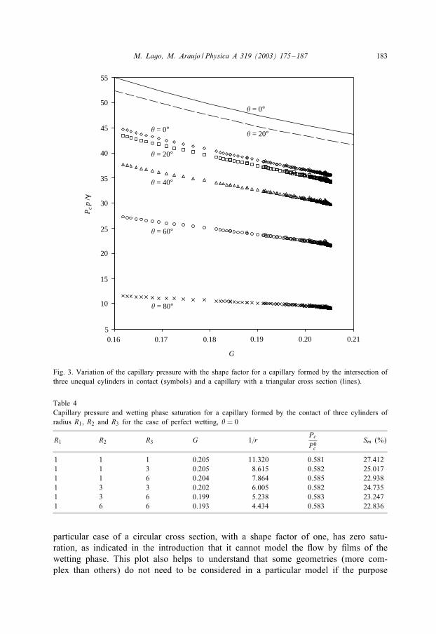
capillaries formed by the contact of cylinders with di5erent radius. The type of cornerobtained from three cylinders in contact introduces important di5erences in the behav-ior of the wetting *uid inside the capillary when compared with the situation found forcapillaries with polygonal (triangular) cross section [12]. As seen from Fig. 3 for the1rst case, there is always a wetting phase when �¡ 90◦. The wetting phase saturationis always greater and the capillary pressure deviates more from its value P0
c (thresholdcapillary pressure for a capillary with circular cross section) estimated for the casewhen there is no wetting phase in the corners. Table 4 summarizes some of the resultsfor the case of perfect wetting in a capillary formed by the contact for three unequalcylinders.

M. Lago, M. Araujo / Physica A 319 (2003) 175–187 181
0
2
4
6
8
10
12
60 65 70 75 80 85 90
60 65 70 75 80 85 90
Point of SeparationP
c R
/ γ
Point of Separation
Pc
/Pc0
� ( ° )
0.55
0.60
0.65
0.70
0.75
0.80
0.85
0.90
0.95
1.00
� = 80°
� = 0°
� ( ° )
� = 0°
� = 80°
Fig. 1. Capillary pressure for the case of four cylinders in contact with some inclination with respect to thehorizontal as a function of the inclination angle. Plots for � = 0◦; 10◦; 20◦; : : : ; 80◦.
From Fig. 3 it is also observed that the ratio Pc=P0c has small variations with the
geometry for a given contact angle. Both the capillary pressure ratio and the transversalwetting phase saturation for this case are very close to the values obtained for the caseof three identical cylinders and two identical cylinders and a plane.
4. Discussion
In this section we compare the behavior of the capillary pressure and the transversalwetting phase saturation for the di5erent geometries considered in this study, valid

182 M. Lago, M. Araujo / Physica A 319 (2003) 175–187
0
10
20
30
60 65 70 75 80 85 90
Point of Separation
S w (
%)
� ( ° )
� = 80°
� = 0°
Fig. 2. Wetting phase saturation as a function of the inclination angle for the case of four identical cylindersin contact. Plots for � = 0◦; 10◦; 20◦; : : : ; 80◦.
for the case of a non-wetting phase droplet lying horizontally inside a capillary withnon-circular cross section.Fig. 4 displays the dependence of the normalized capillary pressure Pc=P0
c with theshape factor for the case of perfect wetting. For those capillaries formed by the contactof two cylinders and a plane, and between one cylinder and a plane, it was necessaryto calculate additional points to cover the region near G zero. Additionally, for thecapillary formed by the contact if three unequal cylinders, several curves were obtainedby variation of the radius R3 keeping constant R1 = 1 and R2 = xR1 + (1 − x)R3, conx∈ [0:0; 1:0].It is observed that the curve for the triangular cross section seems to continue on
the sequence of points correspondent to the regular polygonal sections such as theequilateral triangle, the square, the hexagon and the circle, which can be seen as apolygon with an in1nite number of sides. When G gets close to zero, we may 1ndany value between zero and one, for the normalized ratio Pc=P0
c . The value one isobtained for example, for a rectangle with a side in1nitesimally larger than the other.The other extreme is obtained when the irregularity of the capillary walls is increased,in this case the perimeter of the cross section increases whereas the transversal areais kept constant, both G and Pc=P0
c go to zero. However, as the cross sectional shaperesembles more a circle, both G and Pc=P0
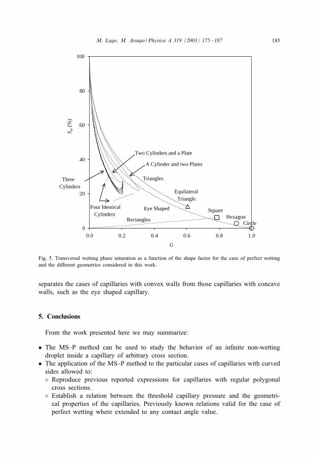
c have values increasing towards one. Thereare also regions on the diagram that will not be occupied by any capillarygeometry.The dependence of the transversal wetting phase saturation with the shape factor
for the case of perfect wetting is shown in Fig. 5. It is observed how the wettingphase saturation decreases rapidly with the shape factor for almost all the cases. The
M. Lago, M. Araujo / Physica A 319 (2003) 175–187 183
5
10
15
20
25
30
35
40
45
50
55
0.16
G
Pc
p /γ
0.210.200.190.180.17
� = 80°
� = 60°
� = 40°
� = 20°
� = 0°� = 20°
� = 0°
Fig. 3. Variation of the capillary pressure with the shape factor for a capillary formed by the intersection ofthree unequal cylinders in contact (symbols) and a capillary with a triangular cross section (lines).
Table 4Capillary pressure and wetting phase saturation for a capillary formed by the contact of three cylinders ofradius R1, R2 and R3 for the case of perfect wetting, � = 0
R1 R2 R3 G 1=rPc
P0c
Sm (%)
1 1 1 0.205 11.320 0.581 27.4121 1 3 0.205 8.615 0.582 25.0171 1 6 0.204 7.864 0.585 22.9381 3 3 0.202 6.005 0.582 24.7351 3 6 0.199 5.238 0.583 23.2471 6 6 0.193 4.434 0.583 22.836
particular case of a circular cross section, with a shape factor of one, has zero satu-ration, as indicated in the introduction that it cannot model the *ow by 1lms of thewetting phase. This plot also helps to understand that some geometries (more com-plex than others) do not need to be considered in a particular model if the purpose

184 M. Lago, M. Araujo / Physica A 319 (2003) 175–187
0.3
0.4
0.5
0.6
0.7
0.8
0.9
1.0
0.0
G
Circle P
c /P
c0Rectangles
Triangles
Equilateral Triangle
Square
Hexagon
Eye Shaped
A Cylinder and two Plates
Two Cylinders and a Plate
Three Cylinders
Four Identical Cylinders
1.00.80.60.40.2
Fig. 4. Normalized capillary pressure as a function of the shape factor for the case of perfect wetting andthe di5erent geometries considered in this work.
is to describe properly the behavior of the saturation of the wetting phase in thecapillary.Another important relation is the one found from the plot of the normalized cap-
illary pressure as a function of the wetting phase saturation, displayed on Fig. 6. Itis important to note that this is not the conventional capillary pressure curve usedin *ow modeling, since the capillary pressure estimated here is the minimum pressureneeded to 1ll the capillary with non-wetting *uid. The commonly known capillary pres-sure was 1rst reported by Mason and Morrow [2] for a capillary with a non-circularcross section, and later on, the curve was obtained from a size distribution of thecapillaries [12–14].In Fig. 6, it is seen that all the capillaries with polygonal cross section follow
a general relation valid when each meniscus occupy a given vertex. When there isa meniscus that occupies several vertexes, it is easily understood that the capillarypressure is the same. However, the shape factor and the wetting phase saturation aresmaller. Therefore, we expect that the regions of the plots that correspond to thesecases remain below the trend lines of the polygonal capillaries studied. In this 1gure,we can also see how the characteristic curve for capillaries with polygonal cross section,
M. Lago, M. Araujo / Physica A 319 (2003) 175–187 185
0
20
40
60
80
100
0.0 0.2 0.4 0.6 0.8 1.0
G
Circle
S w (
%)
Rectangles
Triangles
Equilateral Triangle
Square Hexagon
Eye Shaped
A Cylinder and two Plates
Two Cylinders and a Plate
Three Cylinders
Four Identical Cylinders
Fig. 5. Transversal wetting phase saturation as a function of the shape factor for the case of perfect wettingand the di5erent geometries considered in this work.
separates the cases of capillaries with convex walls from those capillaries with concavewalls, such as the eye shaped capillary.
5. Conclusions
From the work presented here we may summarize:
• The MS–P method can be used to study the behavior of an in1nite non-wettingdroplet inside a capillary of arbitrary cross section.
• The application of the MS–P method to the particular cases of capillaries with curvedsides allowed to:◦ Reproduce previous reported expressions for capillaries with regular polygonalcross sections.
◦ Establish a relation between the threshold capillary pressure and the geometri-cal properties of the capillaries. Previously known relations valid for the case ofperfect wetting where extended to any contact angle value.

186 M. Lago, M. Araujo / Physica A 319 (2003) 175–187
0.3
0.4
0.5
0.6
0.7
0.8
0.9
1.0
0 20
G
Triangles
Eye Shaped
A Cylinder
and two Plates
Three
Cylinders
Four Identical
Cylinders
Pc /P
c0
100806040
Fig. 6. Normalized capillary pressure as a function of the transversal wetting phase saturation for the caseof perfect wetting.
◦ Understand the relation between capillary pressure and wetting phase saturationas a function of the shape factor of the capillary cross section. It is found thatseparated regions describe the behavior of di5erent types of capillaries, for examplethose with convex wall from the ones with concave walls.
Acknowledgements
The authors thank PDVSA-Intevep for permission to publish this paper.
References
[1] R. Lenormand, C. Zarcone, Society of Petroleum Engineers, SPE paper 13264, 1984.[2] G. Mason, N. Morrow, J. Colloid Interface Sci. 141 (1) (1991) 262–274.[3] H. Princen, Colloids Surf. 65 (1992) 221–230.

M. Lago, M. Araujo / Physica A 319 (2003) 175–187 187
[4] K. Mogensen, E. Stenby, Transp. Porous Media 32 (1998) 299–327.[5] M. Blunt, SPE J. 2 (1997) 494–510, SPE paper 38435, 1997.[6] R. Mayer, R. Stowe, J. Colloid Interface Sci. 20 (1965) 893–911.[7] H. Princen, J. Colloid Interface Sci. 30 (1) (1969) 69–75.[8] H. Princen, J. Colloid Interface Sci. 30 (3) (1969) 359–371.[9] H. Princen, J. Colloid Interface Sci. 34 (2) (1970) 171–184.[10] G. Mason, N. Morrow, J. Colloid Interface Sci. 100 (2) (1984) 519–535.[11] F.A.L. Dullien, Porous Media: Fluid Transport and Pore Structure, 2nd Edition, Academic Press,
New York, USA, 1992.[12] M. Lago, M. Araujo, J. Colloid Interface Sci. 243 (2001) 219–226.[13] H. Princen, Colloids Surf. 65 (1992) 221–230.[14] A. Kovscek, H. Wong, C. Radke, AIChE J. 39 (6) (1993) 1072–1085.