Mitigating Collisions through Power-Hopping to Improve 802.11 Performance
25
Mitigating Collisions through Power-Hopping to Improve 802.11 Performance ⋆ Paul Patras ∗ , Hanghang Qi, David Malone Hamilton Institute, National University of Ireland Maynooth, Ireland Abstract In this article, we introduce a power-hopping technique (PH-MAC) that, by alternating be- tween different transmission power levels, aims to deliberately cause packet capture and thereby reduce the impact of collisions in 802.11 WLANs. We first devise an analytical model of the 802.11 protocol with heterogeneous capture probabilities, and show that, de- pending on the network load, the capture effect can enhance the throughput performance of all nodes. We base the design of PH-MAC on the findings following from this analysis and demonstrate that important performance improvements can be achieved by exploiting the interactions between the MAC and PHY layers to mitigate collisions. Finally, to un- derstand the feasibility of this technique in practical deployments, we present a prototype implementation of PH-MAC which relies on commodity hardware and open-source drivers. We evaluate the performance of this implementation in an indoor testbed under different network conditions in terms of link qualities, network loads and traffic types. The experi- mental results obtained show that our scheme can provide significant gains over the default 802.11 mechanism in terms of throughput, fairness and delay. Key words: 802.11, power-hopping, capture effect 1 Introduction In practical IEEE 802.11 deployments, when two or more simultaneous transmis- sions occur on the channel, if frames arrive at the destination with different power ⋆ The research leading to these results has received funding from the European Com- munity’s 7 th Framework Programme (FP7-ICT-2009-5) under grant no. 257263 (FLAVIA project), the Irish HEA PRTLI Cycle 4 FutureComm and Science Foundation Ireland grant no. 07/SK/I1216a. ∗ Corresponding author. Address: NUI Maynooth, Co. Kildare, Ireland. Preprint submitted to Elsevier
Transcript of Mitigating Collisions through Power-Hopping to Improve 802.11 Performance
Mitigating Collisions through Power-Hopping toImprove 802.11 Performance ⋆
Paul Patras∗, Hanghang Qi, David Malone
Hamilton Institute, National University of Ireland Maynooth, Ireland
Abstract
In this article, we introduce a power-hopping technique (PH-MAC) that, byalternating be-tween different transmission power levels, aims to deliberately cause packet capture andthereby reduce the impact of collisions in 802.11 WLANs. We first devise ananalyticalmodel of the 802.11 protocol with heterogeneous capture probabilities, and show that, de-pending on the network load, the capture effect can enhance the throughput performanceof all nodes. We base the design of PH-MAC on the findings following fromthis analysisand demonstrate that important performance improvements can be achieved by exploitingthe interactions between the MAC and PHY layers to mitigate collisions. Finally, to un-derstand the feasibility of this technique in practical deployments, we present a prototypeimplementation of PH-MAC which relies on commodity hardware and open-source drivers.We evaluate the performance of this implementation in an indoor testbed under differentnetwork conditions in terms of link qualities, network loads and traffic types. The experi-mental results obtained show that our scheme can provide significant gainsover the default802.11 mechanism in terms of throughput, fairness and delay.
Key words: 802.11, power-hopping, capture effect
1 Introduction
In practical IEEE 802.11 deployments, when two or more simultaneous transmis-sions occur on the channel, if frames arrive at the destination with different power
⋆ The research leading to these results has received funding from the European Com-munity’s 7th Framework Programme (FP7-ICT-2009-5) under grant no. 257263 (FLAVIAproject), the Irish HEA PRTLI Cycle 4 FutureComm and Science FoundationIreland grantno. 07/SK/I1216a.∗ Corresponding author. Address: NUI Maynooth, Co. Kildare, Ireland.
Preprint submitted to Elsevier
levels, it is often the case that the one received with the strongest signal can be de-modulated despite the interference caused by the others, provided the difference intheir signal strength is sufficiently large. This phenomenon is referred to as thecap-ture effect and has been widely neglected when modeling the IEEE 802.11 protocolbehaviour, the common assumption being that simultaneous transmissions result incollisions [1–4].
Recent works show both analytically and experimentally thatthe capture effectcan potentially reduce the number of failures due to collisions and thus increasethe throughput performance of the network [5–11]. However,we argue that theinteractions between the MAC and PHY layers in the presence of the capture effecthave not been yet deeply understood, since existing studiesneglect the impact oftraffic load and postulate that only nodes that deliver frames at high signal levels(generally due to their better placement relative to the access point) benefit fromcapture.
In contrast to previous works, in this paper we first devise ananalytical model ofthe 802.11 operation under the capture effect and show that this phenomenon cannot only improve the overall throughput of the network, but may also enhance theperformance of the nodes that deliver frames at a low signal level, when the stationsexperiencing better link qualities with the receiver are lightly loaded. Specifically,we show that, depending on the network load, the throughput attained by the sta-tions residing further away from the access point (AP) is notalways degraded dueto nodes located near the AP capturing the channel, but, on the contrary, the captureeffect can also reduce the collision rate encountered by thedistant users, therebyproviding them with larger throughput. Our model adopts a renewal-reward pro-cess [3] to model the binary exponential backoff scheme of the MAC protocol andextends our previous analysis of [12] by considering a fullyheterogeneous network,i.e. distinguishing multiple classes of nodes that experience dissimilar capture prob-abilities.
Based on the valuable insights that follow this analysis, we introduce apower-hopping MAC/PHY scheme (PH-MAC) that exploits the identified protocolbe-haviour to boost the WLAN performance. Specifically, our proposal preserves the802.11 MAC rules, but selects among different power levels with certain proba-bilities when transmitting frames, deliberately causing capture to mitigate colli-sions. This design extends our earlier work [12], which assumed stations could onlychoose among a high and a lower power level. Here, we allow formultiple discretepower levels and also investigate the impact of their number. We model this en-hancement using a Bianchi-type Markov chain [1] and show that, by choosing thepower levels with equal probabilities, PH-MAC reduces the impact of collisions,providing significantly better throughput performance as compared to the standard802.11 protocol.
To evaluate the potential gains of our mechanism, we implement a practical approx-
2
imation of PH-MAC using open-source drivers and off-the-shelf 802.11 hardware.We assess the performance of this prototype by conducting extensive experimentsin a small-scale indoor testbed, under different conditions in terms of link quali-ties, network loads and traffic types. The obtained results show that PH-MAC canachieve noteworthy performance gains over the default 802.11 scheme in terms oftotal throughput, fairness and delay, without requiring any changes to the existinghardware, but only small modifications to the available device drivers.
The rest of the paper is organised as follows: in Section 2, wereview relevant re-lated work; in Section 3 we present the network model considered for our analysis;in Section 4 we undertake an analytical and numerical study of the 802.11 per-formance with heterogeneous capture; in Section 5, we present the power-hoppingMAC scheme that we implement and validate both numerically and via experimentswith real devices; finally, Section 6 concludes the paper.
2 Related Work
Aspects of the capture effect have been widely studied in thepast in the contextof mobile radio environments, e.g. [13, 14].Despite the significant effort devotedto modelling the performance of 802.11 DCF (see e.g. [1–4]), the capture effect islargely ignored in these studies, as well as in recent publications that investigatethe behaviour of the EDCA protocol enhancement [15–17]. To date few analyticalmodelsof the capture probability in Rayleigh fading channels have been proposedand used to predict the impact of this effect on the capacity of 802.11 networks,e.g. [6, 7]. Ge et al. [5] take a further step towards understanding how capture af-fects the back-off mechanism of the protocol, while Sutton et al. [8] introduce amore detailed 3-dimensional Markov chain model that incorporates capture andserves estimating not only failure probability, but also several QoS metrics. How-ever, the failure probability is computed by subtracting a capture probability fromthe collision probability. Instead, in our analysis we treat a fraction of the collisionsas resulting in capture.
Experimental studies have examined the capture phenomenoncomprehensivelywith real deployments, identifying the throughput unfairness that may arise due tothis effect [9,18]. A deeper understanding of how frame timing and signal strengthinfluence the occurrence of capture in practice is provided in [10,11]. Based on thearrival time of a frame with a stronger signal relative to thearrival of weak signalpacket, Manweiler et al. distinguish between capture and message-in-message phe-nomena, and exploit the latter to improve network throughput [19]. To the best ofour knowledge, no previous approaches adjust the transmission power to purposelycause capture and benefit from this effect.
Transmit power control techniques have been employed to improve the energy-
3
efficiency of the 802.11 DCF [20] or for mitigating interference in multi-AP de-ployments [21]. A combined rate and power control scheme is proposed in [22] toimprove battery-life of mobile devices, while avoiding link asymmetries and im-proving capacity. These works, confirm the feasibility of dynamically adapting thetransmission power with current 802.11 devices, which constitutes one the moti-vations behind the design of the power-hopping technique wepropose herein forreducing the impact of collisions. However, as compared to these approaches, ourobjective is to better understand the PHY/ MAC interactionsunder the capture ef-fect and exploit those in dense environments to enhance network performance.
3 Network Model
In this section, we provide an overview of the network model and the assumptionsused in the performance analysis that we conduct. We consider the case of infras-tructure 802.11 wireless networks, i.e. all transmissionsare to/from the AP. Westart by introducing relevant aspects of the IEEE 802.11 protocol with the DCF(Distributed Coordination Function) operation, which is the default channel accessscheme currently employed in WLANs [23] and then explain how capture is ac-counted for in our system.
3.1 IEEE 802.11 DCF
DCF uses a CSMA/CA (Carrier Sense Multiple Access with Collision Avoidance)MAC protocol with binary slotted exponential backoff. Briefly, when a station hav-ing packets to send senses the wireless medium idle for a period of DIFS (Dis-tributed Inter-frame Space), it initialises a backoff counter with a random valueuniformly distributed in the[0, CW ] interval and enters a countdown state. Specif-ically, as long as the medium remains idle, the node decrements its backoff counterby one after each slot timeσ, and suspends the countdown if the medium becomesbusy. The countdown is resumed once the medium is idle again and when the back-off counter reaches zero, the station transmits. TheCW parameter is called the
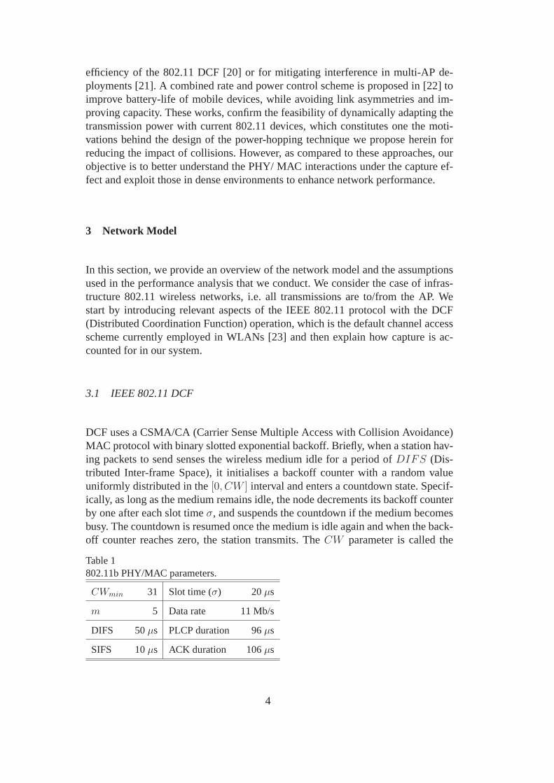
Table 1802.11b PHY/MAC parameters.
CWmin 31 Slot time (σ) 20µs
m 5 Data rate 11 Mb/s
DIFS 50µs PLCP duration 96µs
SIFS 10µs ACK duration 106µs
4
contention window and its value is set to a defaultCWmin upon the first transmis-sion attempt.
If a transmitted frame is successfully received, the destination sends back an ac-knowledgement (ACK) frame after a period ofSIFS (Short Inter-frame Space) tonotify the sender of the correct reception. In thr case wherethe backoff counters oftwo or more stations reach zero simultaneously, the stations transmit in the sametime slot and thus a collision occurs. If the destination cannot decode a frame, noACK is sent back. When a station does not receive an ACK within a predeterminedtimeout, it will double itsCW value and re-enter the backoff process, attemptingto resend the frame. Upon consecutive unsuccessful transmission attempts,CWcan be doubled up to a maximum valueCWmax = 2m(CWmin + 1)− 1, wheremdenotes the maximum backoff stage. If further attempts fail, CW is maintained atthe maximum value and eventually the frame is discarded after a consecutive retrylimit K is exceeded. Otherwise, if the transmission is successful,theCW is resettoCWmin. The values of the involved parameters are summarised in Table 1 for theHR/DSSS (802.11b) physical layer [23].
3.2 System Assumptions
We consider a WLAN where nodes are within carrier sense range of one anotherand do not employ the RTS/CTS mechanism, as previous studies show this 4-wayhandshake procedure provides limited benefits in the absence of hidden termi-nals [24], while if used in combination with power control, it can harm throughputperformance [25]. Our analysis, however, could be easily extended also to this case.We assume ideal channel conditions, therefore losses are only caused by collisions.Without loss of generality, we assume stations send fixed size packets and employa single PHY rate. These assumptions are commonly used in theliterature [1–4]and could be relaxed, but we expect that they do not significantly change our con-clusions.
We analyse the 802.11 MAC behaviour with heterogeneous capture, distinguishing
AP
Class 1
Class 2
Class Z
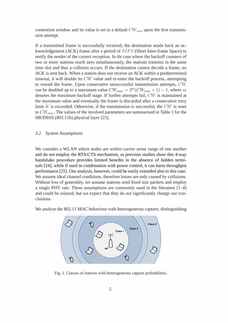
Fig. 1. Classes of stations with heterogeneous capture probabilities.
5
Z classes of nodes that experience dissimilar capture probabilities as a result oftheir placement relative to the AP. We index the classes according to their likelihoodof capturing, as depicted in Fig. 1, i.e. the lower the class index, the closer a nodewithin that class is to the AP and the more plausible it will beto capture whentransmitting simultaneously with nodes of classes with higher indexes.
As such, nodes within any Classj can capture the channel over nodes in Classl,∀l > j. Consequently, when concurrent transmissions occur, the following out-comes are possible:
• If a station in Classj and respectively a node in Classl, l > j, transmit⇒ stationin Classj captures with probabilityαj,l; transmission of station in Classl fails;
• If a station in Classj transmits simultaneously with any other station in Classl,l ≤ j, ⇒ transmission fails.
We treat the capture probabilitiesαj,l as model parameters, while methods givenin e.g. [6, 7] can be employed to accurately estimate their values. In what follows,we study the 802.11 throughput performance under differentnetwork loads in thepresence of capture, to identify those scenarios in which all classes of stations couldbenefit from this effect.
4 Performance Analysis of 802.11 with Heterogeneous Capture
To study the performance of a WLAN where stations experience dissimilar captureprobabilities, we first present a throughput model that accounts for this effect andthen employ numerical analysis to illustrate that gains canbe achieved in suchcircumstances, depending on the volume of traffic nodes generate. By investigatingthe relationship between the success probabilities, transmission attempt rates andarrival processes, we provide valuable insights into the observed behaviour.
4.1 Throughput Model
We propose a realistic model of 802.11 operation that, unlike previous works, al-lows nodes with heterogeneous capture probabilities. In the absence of the captureeffect, simultaneous frame transmissions fail due to collisions. In this case, the con-ditional failure (collision) probabilityp experienced by a transmitted frame is givenby [1]:
p = 1− (1− τ)n−1, (1)
whereτ is the stationary probability that a station transmits in a randomly chosenslot time andn is the number of stations in the WLAN.
6

In the presence of the capture effect, a transmission of a station can be success-ful even when another station transmits simultaneously. However, only the framereceived with a higher signal level will be decoded by the AP,while the other trans-mission will result in failure. Denoting bypj the conditional failure probability ofa Classj and byτj the corresponding transmission probability of stations inthatclass, we can relate the probability of success of a station in Classj with the trans-mission probabilities of the other classes as follows:
1− pj =(1− τj)nj−1
Z∏
l=1,l 6=j
(1− τl)nl
+ (1− τj)nj−1
Z∑
l=j+1
(1− (1− τl)nl)αj,l
l−1∏
w=1,w 6=j
(1− τw)nw
, (2)
where, as explained earlier,αj,l is the probability that a station from Classj capturesthe channel over stations from Classl, whilenj , j ∈ {1, .., Z}, denotes the numberof stations belonging to Classj. As in [12], we treat a fraction of the collisionsas resulting in capture, instead of simply subtracting a capture probability fromthe collision probability to compute the failure probability, which is the approachpreviously used by e.g. [5,8].
Next, we use a renewal-reward approach to analyse the 802.11binary exponentialbackoff scheme. The advantage of using this approach is thatit does not requirethe direct calculation of the stationary distribution of the Markov Chain [3,26], butinstead we calculate the expected number of slots and transmissions between therenewal events, i.e. the completion of packet transmissions. Letp be a station’s con-ditional failure probability. The expected number of attempts to transmit a packetis
E(R) = 1 + p+ p2 + ...+ pK , (3)
whereK is the maximum number of retry attempts. The expected numberof slotsused during backoff is
E(X) = ti + b0 + pb1 + p2b2 + ...+ pkbk + ...+ pKbK , (4)
wherebk is the mean length of backoff stagek expressed in slots andti is the meanidle time that a station waits for a packet after transmission. Thus, we can expressthe transmission attempt rate of the station as
τ =E(R)
E(X)=
1 + p+ p2 + ...+ pK
ti + b0 + pb1 + p2b2 + ...+ pKbK. (5)
We apply the above equation to the considered classes of stations to relate eachτjto the correspondingpj.
7

Neglecting post-backoff and assuming no buffering, we can write
ti = q(1 + 2(1− q) + 3(1− q)2 + ...) =1
q, (6)
whereq is the probability that a new frame arrives in a uniform slot timeEs, givenby
Es = Piσ + PsTs + PfTf , (7)
in which σ, Ts andTf are the average durations of an idle slot, a successful trans-mission and a failure respectively, andPi, Ps andPf are the corresponding proba-bilities, given by
Pi =Z∏
j=1
(1− τj)nj , (8)
Ps =Z∑
j=1
njτj(1− pj), (9)
Pf =1− Pi − Ps, (10)
Ts andTf can be expressed as
Ts = TPLCP +E[L]
C+ SIFS + TACK +DIFS,
Tf = TPLCP +E[L]
C+ TACK timeout,
whereTPLCP is the duration of the PLCP (Physical Layer Convergence Protocol)preamble and header,1 L is the average frame length,TACK is the duration of anacknowledgment,C is the PHY rate andTACK timeout is a physical layer constant.
GivenCWmax = 2m(CWmin + 1) − 1 and usingW = CWmin + 1 to simplifynotation, we havebk = 2kW/2, ∀k ≥ 0 and, assuming infinite backoff (K → ∞),we obtain:
τj =2(1− 2pj)
W (1− pj − pj(2pj)m) +2(1−2pj)(1−pj)
q
. (11)
Combining (2) and (11), we can solve (τ1, p1, ..., τZ , pZ) and compute the totalthroughput of the network as follows:
S =PsE[P ]
Es
, (12)
1 E.g. 72 bit PLCP preamble transmitted at 1 Mb/s and 48 bit PLCP header transmitted at2 Mb/s, for HR/DSSS (802.11b) PHY layer with short preamble [23].
8
1
1.5
2
2.5
3
1 2 3 4 5 6 7
Per
cla
ss thro
ughput [M
b/s
]
Per class offered load [Mb/s]
Class 1Class 2No capture
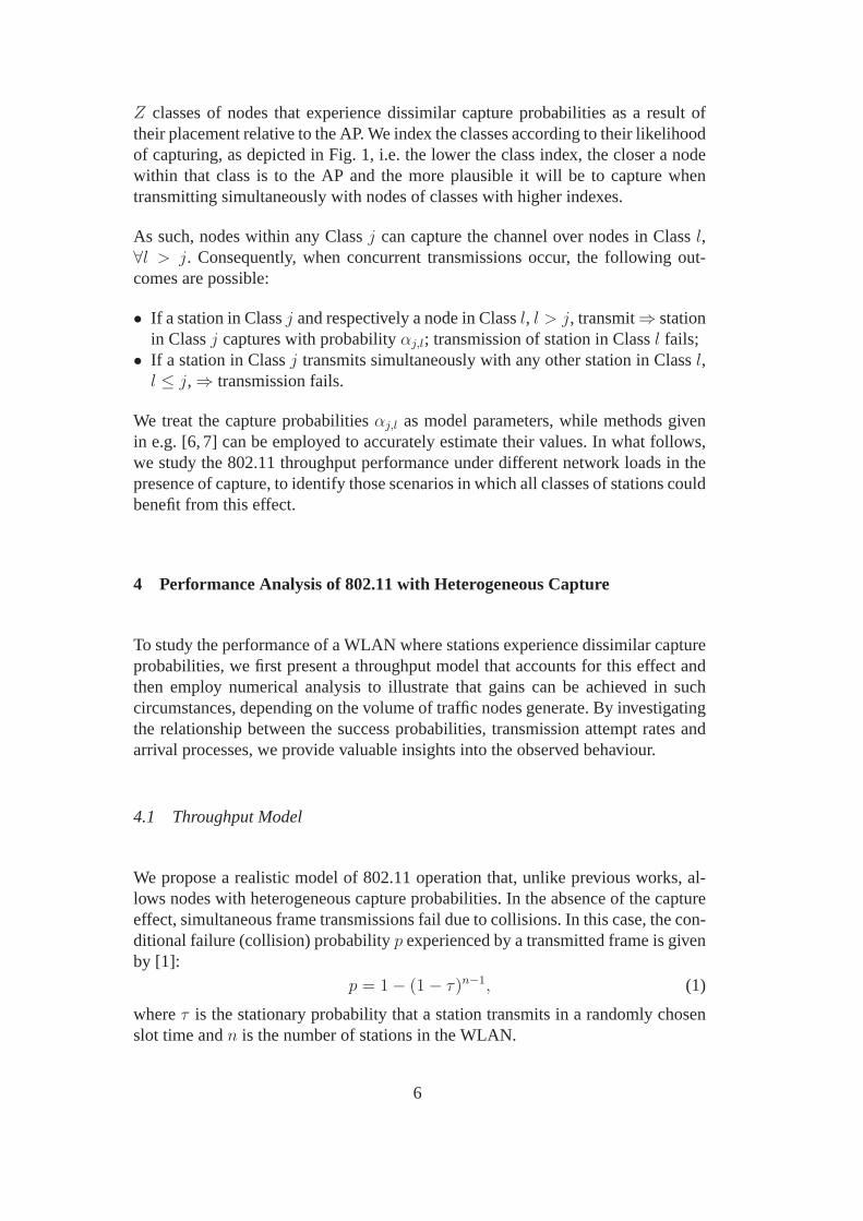
Fig. 2. Throughput performance with and without the capture effect.
whereE[P ] is the expected size of the payload. The above completes our through-put model. Next, we study the impact of the offered load on theperformance at-tained with the capture effect.
4.2 Numerical Results and Discussion
Using the proposed model, we consider a simple example scenario of a networkwith two classes of stations, each class yieldingnj = 5 nodes, and analyse nu-merically the throughput attained by each class as the offered load is varied.2 Weassume stations employ the 802.11b system parameters, as summarised in Table 1,and are transmitting packets of fixed size,E[P ] = 500 bytes. We consider identicalload at each node andα1,2 = 0.75, i.e. a Class 1 station can capture the channelover Class 2 stations 75% of the time.3 Note that the plots we present are ob-tained by numerically evaluating the model in Sec. 4.1, using the above networkparameters along with a fine set of offered load values, and computing the expectedperformance.
The results are shown in Fig. 2, where we also plot for comparison the throughputperformance of an identical network setup but without the capture effect (i.e.α =0). As expected, the throughput of Class 1 is always above the throughput achievedby the same group of stations in a capture-free scenario. However, what is moreinteresting is thatthe throughput of Class 2 can also be larger in the presenceof capture, depending on the offered load of Class 1 stations. Note that althoughthe observed differences may appear small, it is worth comprehending what drivesthese improvements, as we will show later that capture can beexploited when nodes
2 We relate the arrival rate per slotq to the actual packet arrival rate per secondλ, withλ = −log(1− q)/Es. Assuming all the traffic is independent and Poisson, the offered loadis obtained asλE[P ].3 Numerical analysesconducted with different values ofα1,2 yield similar results.
9
40
60
80
100
120
140
160
180
1 2 3 4 5 6 7
Tra
nsm
issio
n r
ate
[attem
pts
/s]
Per class offered load [Mb/s]
Class 1Class 2No capture
120
135
150
3 4
Class 1
Class 2
No capture
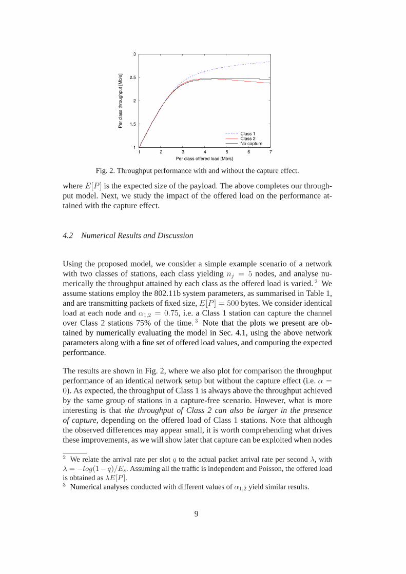
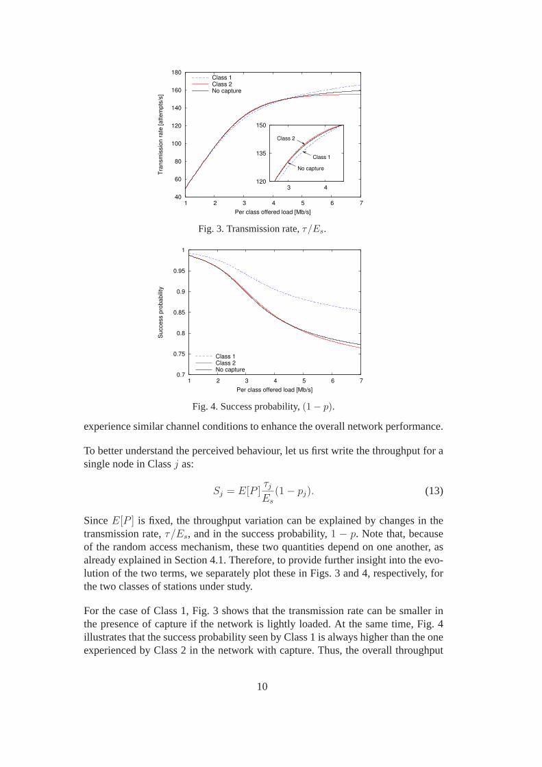
Fig. 3. Transmission rate,τ/Es.
0.7
0.75
0.8
0.85
0.9
0.95
1
1 2 3 4 5 6 7
Success p
robabili
ty
Per class offered load [Mb/s]
Class 1Class 2No capture
Fig. 4. Success probability,(1− p).
experience similar channel conditions to enhance the overall network performance.
To better understand the perceived behaviour, let us first write the throughput for asingle node in Classj as:
Sj = E[P ]τjEs
(1− pj). (13)
SinceE[P ] is fixed, the throughput variation can be explained by changes in thetransmission rate,τ/Es, and in the success probability,1 − p. Note that, becauseof the random access mechanism, these two quantities dependon one another, asalready explained in Section 4.1. Therefore, to provide further insight into the evo-lution of the two terms, we separately plot these in Figs. 3 and 4, respectively, forthe two classes of stations under study.
For the case of Class 1, Fig. 3 shows that the transmission ratecan be smaller inthe presence of capture if the network is lightly loaded. At the same time, Fig. 4illustrates that the success probability seen by Class 1 is always higher than the oneexperienced by Class 2 in the network with capture. Thus, the overall throughput
10
improvements of Class 1 are a nontrivial combination of tradeoffs between trans-mission rate and probability of success.
For the case of Class 2, similar tradeoffs occur. Namely, while the failure probabil-ity, p, increases with the offered load, the success probability,1 − p, can actuallybecome higher than in the equivalent network without capture, allowing the pos-sibility of improved throughput over the capture-free case. At the same time, thetransmission rate of Class 2 is equal or lower in the presence of capture as com-pared to the capture-free case. As the observed transmission rate effectively stopsincreasing at a low offered load while the failure probability continues to increase,this explains the peak in the throughput of Class 2 seen in Fig.2.
To conclude this section, we will study the relationship between transmission andconditional failure probabilities. This will offer insight into how the throughputgains are related to differences in failure probability between the two classes and tothe network load.
It is worth noting that, at very low offered loads, we observethat the transmissionrate of Class 1 is lower than that of Class 2. This may be initially regarded assurprising, since both classes have the same offered load and Class 2 sees ahigherfailure probability. In particular, as stations backoff upon failed attempts, higherfailure probabilities are usually associated with lower transmission probabilities.Given this counter-intuitive behaviour, we further analyse the relationship betweentransmission and failure probabilities.
If we take the derivative of (5) with respect top, we obtain
dτ
dp=
(∑K
k=0 bkpk + 1
q
) (∑K
l=1 lpl−1)
(∑K
k=0 bkpk + 1
q
)2
−
(∑K
k=0 pk) (∑K
l=1 lblpl−1)
(∑K
k=0 bkpk + 1
q
)2 . (14)
Kumar et al. proved that in saturation (i.e.q = 1), if bl >= bk, ∀l > k andbk arenot all equal, thenτ is strictly decreasing withp whenp ∈ (0, 1) [3]. Therefore, theexpression in (14) will be negative.
Conversely, when the network is lightly loaded, from our previous observationabout the attempt rates of the two classes we conjecture thatτ must not be de-creasing. If we evaluate the numerator of (14) when the derivative changes sign, wecan write:
(pm(4m2mp+ (−2m− 2)2m) + 2)q2W
+(8p2 − 8p+ 2)q2 + (−8p2 + 8p− 2)q = 0.
11

0.005
0.01
0.015
0.02
0.025
0.03
0.035
0 0.1 0.2 0.3 0.4 0.5
Tra
nsm
issio
n p
robabili
ty
Conditional failure probability
x
q=0.01q=0.02q=0.03q=0.04q=0.05q=0.06
Fig. 5. Relationship betweenτ andp for different arrival ratesq. The circles indicate themaximum values ofτ .
In a lightly-loaded case (i.e.p ≈ 0), the above is equivalent to:
2q2W + 2q2 − 2q = 0,
which has a root atq0 = 1/(W + 1). Intuitively, this tells us that when the arrivalrate is smaller than one packet everyW + 1 slots, then increasingp can increaseτ ,due to the increased number of retransmission attempts.
In Fig. 5 we plot the relationship betweenτ andp as given by (11) for differentqvalues. We observe that, for non-saturated scenarios, there exists a non-monotonicrelationship between the transmission and collision probabilities, meaning an in-crease inp can increase or decreaseτ . We also mark in the figure the turning pointfor each curve. To the left of this point increases in the failure probability result inincreased transmission rate, and to the right increased failure probability results indecreased transmission rate. Asq increases, we see this point moves towardsp = 0.Following this observation, we could compute theq value where the transmissionrate becomes monotonic.
We conclude that, in the presence of the capture effect, the throughput increasearises from a tradeoff between the transmission and successprobabilities, depend-ing on the stations’ offered load, and cannot be understood in terms of only one ofthe aforementioned quantities alone.
5 Power-hopping MAC
We have shown that in some circumstances the capture effect can boost the per-formance of all stations, as the increased success rate and the reduced numberof retransmissions experienced by nodes near the AP yield anincrease in the airtime available for all contenders. In this section, we take our finding one step fur-
12
ther and we conjecture that, in dense deployments prone to increased contention,by periodically setting the transmission power of stationsto dissimilar levels, itwould be possible to enhance the throughput performance of all stations. There-fore, we design apower-hopping MAC (PH-MAC) scheme that exploits the captureeffect to mitigate collisions, thereby improving the performance of the basic 802.11DCF mechanism. We quantify numerically the benefits of employing the proposedscheme and then present a prototype implementation. We conduct experiments witha real 802.11 deployment and demonstrate that PH-MAC provides significant per-formance gains without requiring changes to the existing hardware, but only someminor modification to the available open-source device drivers.
5.1 PH-MAC Design
Consider a situation where a station has determined that a power levelPmin is suf-ficient to transmit reliably to the AP at the selected PHY rateand assume the maxi-mum transmission power supported by the hardware isPmax. Further, suppose thata station can select fromL discrete levels within a[Pmin, Pmax] range and assumethat the difference between any two distinct levels in the possible range is largeenough to cause capture. Thus, when two stations transmit simultaneously usingdissimilar power levels, the transmission at the higher level will capture with dif-ferent probabilities over the lower power transmission, depending on their relativedifference, and will be successfully decoded at the AP.
Following this observation, the objective of PH-MAC is to choose transmissionpowers so that a significant number of collisions result in capture. To this end,for each transmission attempt, PH-MAC randomly chooses a power level withinthe possible range. Specifically, we select amongL power levels with probabilities{p1, p2, ..., pL}. We consider that stations use the same set of probabilities of choos-ing among distinct power levels. Thus, on average they experience similar captureprobabilities and success rates. Further, our design is intended to use power levelsabove those where successful transmission has become dependable (see [27] for anexperimental assessment of the relationship between packet loss rate and SNR).
The immediate question is how to properly configure these probabilities to optimisethe network performance? To answer this, let us first model the expected behaviourof our proposal. Imagine a single cell 802.11 network withn stations following thebasic DCF rules and employing one ofL power levels at each transmission attempt,as explained above.
Initially, consider a symmetric network, where all stations have the same transmis-sion rateτ . Then, if all frames were transmitted with the same power level, the
13
conditional collision probabilitypc could be written as
pc = 1− (1− τ)n−1 =n−1∑
i=1
(
n− 1
i
)
τ i(1− τ)n−i−1. (15)
However, since we employ the power-hopping scheme, some of the simultaneoustransmissions will be successfully decoded because of capture, while others willstill fail. Thus, the failure probabilityp is given by
p =n−1∑
i=1
(
n− 1
i
)
τ i(1− τ)n−i−1[
p1(1− (p2 + p3 + ...+ pL)i)
+ p2(1− (p3 + p4 + ...+ pL)i) + ...+ pL−1(1− piL) + pL
]
,
which can be reduced to
p =n−1∑
i=1
(
n− 1
i
)
τ i(1− τ)n−i−1L∑
l=1
pl
1−
L∑
k=l+1
pk
i
. (16)
Given that in practiceτ takes small values (i.e.τ ≪ 1), the term corresponding toi = 1 dominates the expression of the conditional failure probability given by (16).Thus we can approximatep by
p ≈ pc
1−L−1∑
l=1
plL∑
k=l+1
pk
︸ ︷︷ ︸
no cap
.
Examining the above, we reason that, in a case where failuresare dominated bycollisions of two stations, the failure probability will bescaled by the term denotedno cap relative to the collision probabilitypc (of the capture-free case). Thus, inorder to optimise performance we need to find the set of{p1, ...pL} probabilitiesthat minimise the failure probability, which is equivalentto solving the followingoptimisation problem:
min{p1,...,pL}
no cap (17)
s.t.L∑
l=1
pl = 1, (18)
0 ≤ pl ≥ 1, l = 1, ..., L. (19)
The corresponding Lagrangian is given by
L(p, λ) = no cap+ λ
(L∑
l=1
pl − 1
)
(20)
14
0 0.2
0.4 0.6
0.8 1 0
0.2 0.4
0.6 0.8
1
5
5.2
5.4
5.6
5.8
Tota
l th
roughput [M
b/s
]
p1
p2
Tota
l th
roughput [M
b/s
]
5.1
5.2
5.3
5.4
5.5
5.6
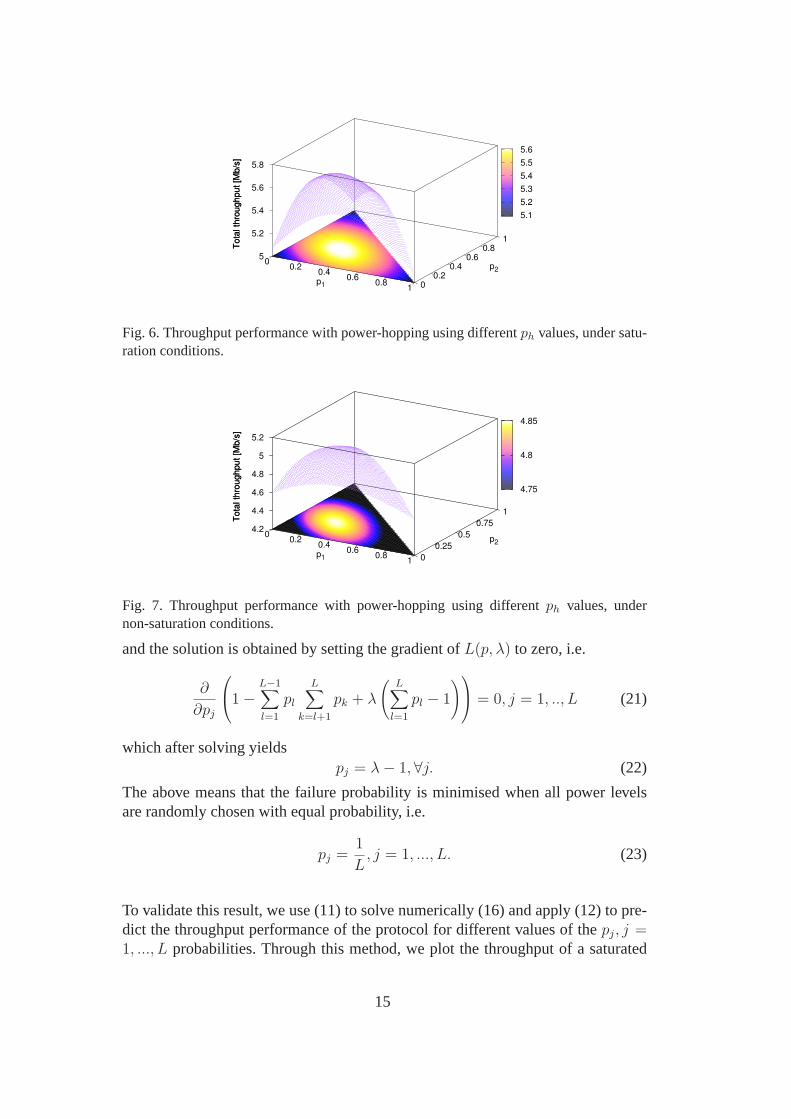
Fig. 6. Throughput performance with power-hopping using differentph values, under satu-ration conditions.
0 0.2
0.4 0.6
0.8 1 0
0.25
0.5
0.75
1
4.2
4.4
4.6
4.8
5
5.2
Tota
l th
roughput [M
b/s
]
p1
p2
Tota
l th
roughput [M
b/s
]
4.75
4.8
4.85
Fig. 7. Throughput performance with power-hopping using differentph values, undernon-saturation conditions.
and the solution is obtained by setting the gradient ofL(p, λ) to zero, i.e.
∂
∂pj
1−L−1∑
l=1
plL∑
k=l+1
pk + λ
(L∑
l=1
pl − 1
)
= 0, j = 1, .., L (21)
which after solving yieldspj = λ− 1, ∀j. (22)
The above means that the failure probability is minimised when all power levelsare randomly chosen with equal probability, i.e.
pj =1
L, j = 1, ..., L. (23)
To validate this result, we use (11) to solve numerically (16) and apply (12) to pre-dict the throughput performance of the protocol for different values of thepj, j =1, ..., L probabilities. Through this method, we plot the throughputof a saturated
15
and non-saturated network withn = 10 stations in Figs. 6 and 7 respectively, forthe possible range ofpj values, considering nodes choose fromL = 3 power lev-els. Clearly, in both cases, choosingpj = 1/3, ∀j provides noticeable performancebenefits as compared to the capture-free scenario (pj = 1 andpk = 0, ∀k 6= j).
5.2 Numerical Results
To estimate the benefits of using the proposed scheme, we firstinvestigate numeri-cally the throughput performance of PH-MAC as compared to the standard 802.11MAC, varying the network conditions in terms of numbers of active stations andconsidering different offered loads.
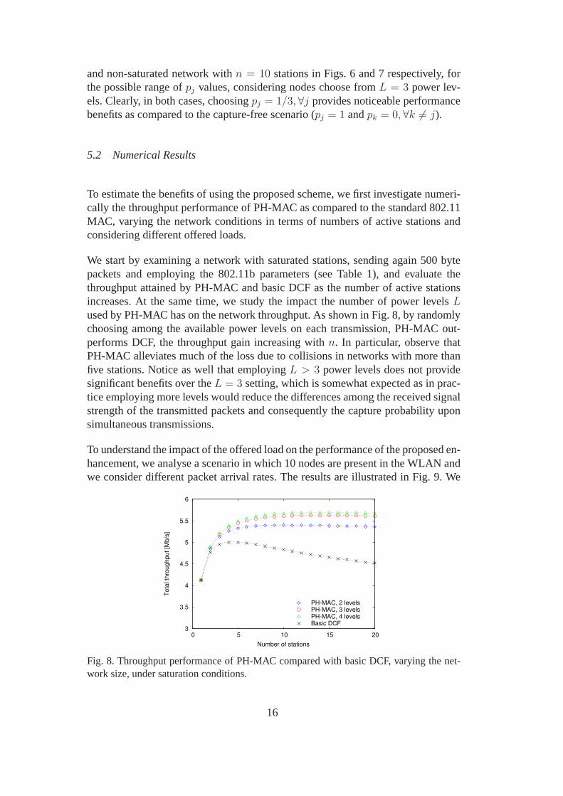
We start by examining a network with saturated stations, sending again 500 bytepackets and employing the 802.11b parameters (see Table 1),and evaluate thethroughput attained by PH-MAC and basic DCF as the number of active stationsincreases. At the same time, we study the impact the number ofpower levelsLused by PH-MAC has on the network throughput. As shown in Fig.8, by randomlychoosing among the available power levels on each transmission, PH-MAC out-performs DCF, the throughput gain increasing withn. In particular, observe thatPH-MAC alleviates much of the loss due to collisions in networks with more thanfive stations. Notice as well that employingL > 3 power levels does not providesignificant benefits over theL = 3 setting, which is somewhat expected as in prac-tice employing more levels would reduce the differences among the received signalstrength of the transmitted packets and consequently the capture probability uponsimultaneous transmissions.
To understand the impact of the offered load on the performance of the proposed en-hancement, we analyse a scenario in which 10 nodes are present in the WLAN andwe consider different packet arrival rates. The results areillustrated in Fig. 9. We
3
3.5
4
4.5
5
5.5
6
0 5 10 15 20
Tota
l th
roughput [M
b/s
]
Number of stations
PH-MAC, 2 levelsPH-MAC, 3 levelsPH-MAC, 4 levelsBasic DCF
Fig. 8. Throughput performance of PH-MAC compared with basic DCF, varying the net-work size, under saturation conditions.
16
2
3
4
5
6
2 4 6 8 10 12
Tota
l th
roughput [M
b/s
]
Total offered load [Mb/s]
PH-MAC, 2 levelsPH-MAC, 3 levelsPH-MAC, 4 levelsBasic DCF
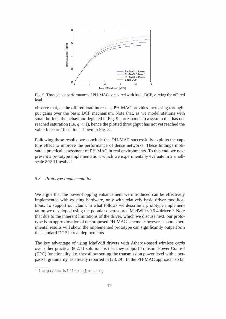
Fig. 9. Throughput performance of PH-MAC compared with basic DCF, varying the offeredload.
observe that, as the offered load increases, PH-MAC provides increasing through-put gains over the basic DCF mechanism. Note that, as we model stations withsmall buffers, the behaviour depicted in Fig. 9 correspondsto a system that has notreached saturation (i.e.q < 1), hence the plotted throughput has not yet reached thevalue forn = 10 stations shown in Fig. 8.
Following these results, we conclude that PH-MAC successfully exploits the cap-ture effect to improve the performance of dense networks. These findings moti-vate a practical assessment of PH-MAC in real environments.To this end, we nextpresent a prototype implementation, which we experimentally evaluate in a small-scale 802.11 testbed.
5.3 Prototype Implementation
We argue that the power-hopping enhancement we introduced can be effectivelyimplemented with existing hardware, only with relatively basic driver modifica-tions. To support our claim, in what follows we describe a prototype implemen-tation we developed using the popular open-source MadWifi v0.9.4 driver.4 Notethat due to the inherent limitations of the driver, which we discuss next, our proto-type is an approximation of the proposed PH-MAC scheme. However, as our exper-imental results will show, the implemented prototype can significantly outperformthe standard DCF in real deployments.
The key advantage of using MadWifi drivers with Atheros-based wireless cardsover other practical 802.11 solutions is that they support Transmit Power Control(TPC) functionality, i.e. they allow setting the transmission power level with a per-packet granularity, as already reported in [28,29]. In the PH-MAC approach, so far
4 http://madwifi-project.org
17
we have assumed that the power can be changed with each transmission attempt.However, this would require a fine control of the hardware, namely accessing theretransmission-handling routines, that are generally embedded in the hardware ab-straction layer (HAL) or firmware. Unfortunately, the source code implementingthis low-level functionality is not publicly available forthe existing devices. Con-sequently, our prototype only tunes the transmission poweron a per-packet insteadof per-transmission attempt basis. Nonetheless, we expectonly minor deviationsfrom the predicted performance and we will demonstrate that, indeed, our imple-mentation achieves noteworthy throughput gains despite this approximation.
To implement PH-MAC we modified the part of the driver’s source code handlingthe transmission operations for the Atheros wireless LAN controller (if ath).Precisely, when a new packet arrives at the MAC queue, anath tx start rou-tine is invoked to handle the transmission. After performing the encapsulationoperations, computing the transmission duration and selecting the antenna to beused for transmission, the routine prepares a transmissiondescriptor that is used topass the packet to the hardware, along with a set of PHY layer parameters, amongwhich is the transmission power. To achieve the desired power-hopping function-ality, before the transmission descriptor is provided to the hardware through theath hal setuptxdesc call, we update the transmission power parameter re-tained in the node information structure (ni), that is passed at the call, and invoketheath update txpow routine, that sets the TX power of the device to the de-sired level.
Although a predefined set of power levels can be configured, toensure a significantdifference between the power levels used for transmissionsis achieved and a highlikelihood of capture exists even under small deployments,we opt for implementingPH-MAC with L = 2 levels, thus randomly choosing between a low and a highpower with probabilityp1 = p2 = 0.5. To this end, when enqueueing a packet, wegenerate a random unsigned 32-bit number using therandom32 routine, which wecompare to the the value that splits the possible range in half, i.e. 0x7FFFFFFF.The power level passed for update has to be expressed as 0.5 dBmincrements, e.g.for setting the power toPmax = 16 dBm a value of 32 is expected.5 Note thatMAC operation as specified by the standard is kept unmodified.For further detailsabout the implementation, we refer the reader to the source code of the prototype,which we make publicly available online.6 In what follows we validate PH-MAC’soperation in an 802.11 testbed.
5 The maximum power level that can be set on a device varies with manufacturers and issubject to regulatory constraints.6 http://www.hamilton.ie/ppatras/#code
18
5.4 Experimental Evaluation
To evaluate the potential performance benefits of PH-MAC in areal environment,we conduct experiments in a small testbed that we deployed atthe Hamilton In-stitute in Ireland. The network is placed in a dynamic office space with numer-ous occupants and the experiments are conducted during working hours. Thus theradio conditions are typical of an active environment with humans.The testbedconsists of 7 nodes: one PC acting as access point and 6 Soekris net4801 embed-ded PCs serving as clients. All nodes are equipped with Wistron CM9 AtherosminiPCI 802.11b/g cards, 5 dBi omnidirectional antennas, andrun the Ubuntu 8.04LTS Linux distribution with kernel 2.6.24. The WLAN is operating on channel 6(2.437 GHz) where no other networks have been detected and thus we concludeit is an interference free environment. RTS/CTS, turbo, fastframe, bursting andunscheduled automatic power save functionalities are disabled in all experiments,while the antenna diversity scheme is not employed for transmission/reception. Allnodes are within LOS from the AP, thus we expect negligible multipath propagationeffects.
Given the reduced size of our deployment we configure nodes with CWmin = 7andCWmax = 15, to ensure an increased level of contention in the WLAN.7 Thuswe seek to replicate conditions typical of practical scenarios that are subject tomoderate-to-high loads in order to study the performance incircumstances DCFfinds challenging, such as conference halls, libraries, auditoriums, etc. Also, be-cause of the compactness of our testbed, we are free to selectbetween the lowestand highest configurable powers upon transmission, i.e. 0 dBm(1 mW) and 16 dBm(40 mW). This ensures a high likelihood of capture when transmissions at differentlevels overlap. Given the limited capabilities of the stations (266 MHz CPU and128 MB physical memory), we configure their PHY rate to 11 Mb/s(CCK). Weexpect, however, that our findings will hold also for the OFDMPHY, as captureoccurs for all non-linear modulation-based 802.11 PHY layer technologies [10]. Inall tests, we disable rate adaptation, but recognize that capture probability couldchange depending on the PHY rate in use.8 We expect similar qualitative results insuch scenarios.With these settings, we proceed with comparing the performanceof PH-MAC and basic DCF under different network conditions interms of linkquality, application type and traffic loads.
7 Note that these are realistic MAC settings, as they are employed for e.g. the video queueof the 802.11a/g modes.8 We refer the reader to [10] for a detailed discussion on the relationship between PHYrate and SIR threshold for capture.
19

Table 2RSSI footprint of the testbed with nodes transmitting at 16 dBm.
Homogeneous environment Heterogeneous environment
Station index RSSI average RSSI std. dev. RSSI average RSSI std. dev.
index [dBm] [dB] [dBm] [dB]
1 -39.4 4.2 -51.6 4.0
2 -39.5 4.5 -38.0 5.9
3 -38.8 3.6 -41.0 3.9
4 -38.4 4.1 -47.3 4.2
5 -38.4 3.7 -50.4 3.5
6 -39.4 3.8 -40.6 4.8
Avg. min. -39.5 -51.6
Avg. max. -38.4 -38.0
5.4.1 Homogeneous Environment
We first consider a homogeneous environment, whereby clients experience sim-ilar link qualities to the AP. For this purpose, we position the nodes at compa-rable distances from the AP to guarantee frames are receivedwith similar signalstrength when transmitted at the same power level. To confirmthis, we periodicallysend ICMP traffic between each station and the AP, and record the received signalstrength indicators (RSSI) for the received frames as reported in theradiotapheader of the packets sniffed withtcpdump. Specifically, nodes send sequentially10 probe requests, with 1 second spacing in between, and packet size of 1000 bytes.After each round, stations pause for 1 minute and then repeatthis process 5 times,to capture link quality variations due to external factors such as human interference.In Table 2, on the left side, we providethe average and standard deviation of theRSSI for each node sending at maximum TX power. We observe that, indeed, allnodes experience almost identical link qualities when sending to the AP.
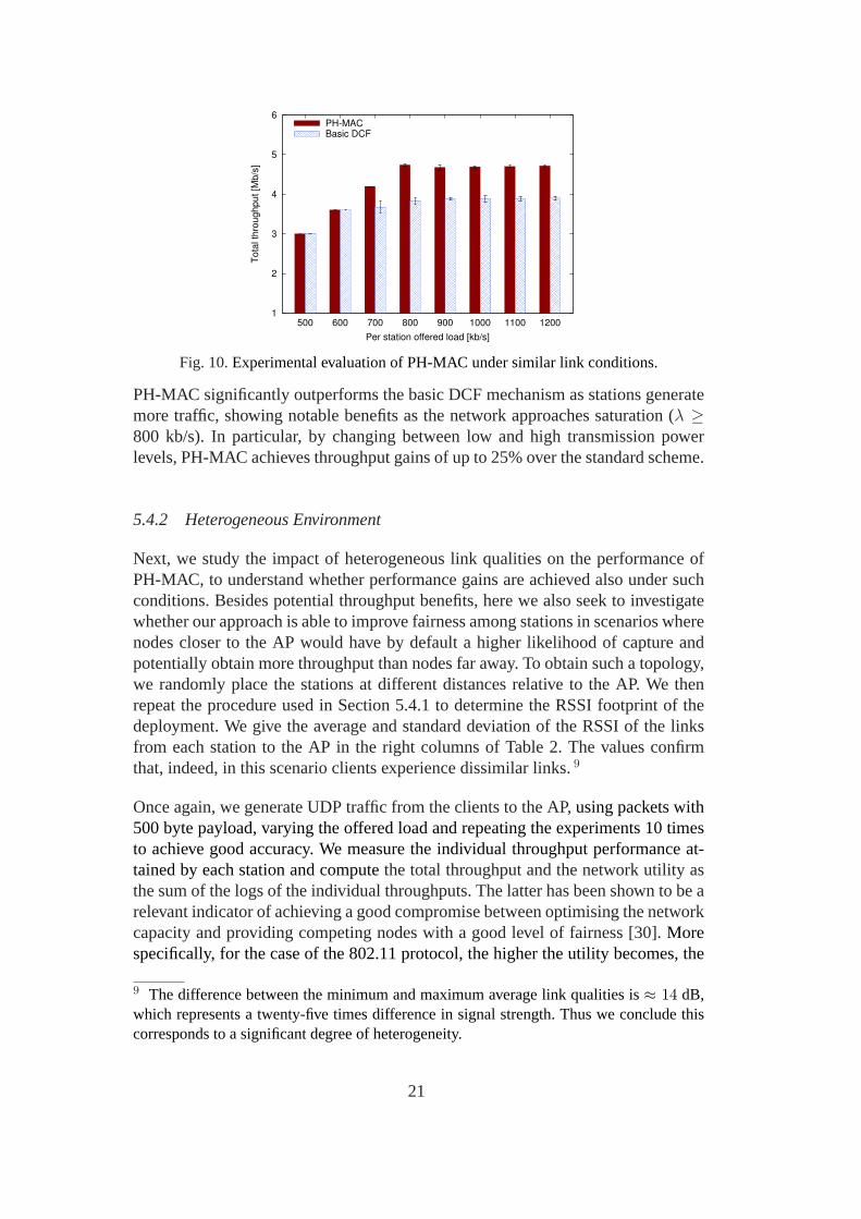
Following these preliminary measurements, we investigatethe performance gainsof PH-MAC when stations send UDP traffic to the AP. To this end,we use theiperf tool to generate UDP packets with 500 byte payload, uniformly varyingthe offered load at each node and recording the total throughput at the AP, firstwhen clients employ PH-MAC, alternating between the minimumand maximumpower levels for transmissions, and then with the basic DCF mechanism in place.Each experiment runs for 3 minutes and is repeated 10 times, to obtain averagevalues of the throughput with good statistical significance.
The results are shown in Fig. 10, where we plot average and 95%confidence inter-vals of the throughput obtained with the two approaches. As observed in the figure,
20
1
2
3
4
5
6
500 600 700 800 900 1000 1100 1200
Tota
l th
roughput [M
b/s
]
Per station offered load [kb/s]
PH-MACBasic DCF
Fig. 10.Experimental evaluation of PH-MAC under similar link conditions.
PH-MAC significantly outperforms the basic DCF mechanism as stations generatemore traffic, showing notable benefits as the network approaches saturation (λ ≥800 kb/s). In particular, by changing between low and high transmission powerlevels, PH-MAC achieves throughput gains of up to 25% over the standard scheme.
5.4.2 Heterogeneous Environment
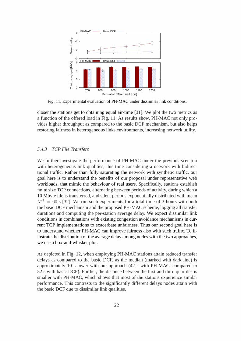
Next, we study the impact of heterogeneous link qualities onthe performance ofPH-MAC, to understand whether performance gains are achieved also under suchconditions. Besides potential throughput benefits, here we also seek to investigatewhether our approach is able to improve fairness among stations in scenarios wherenodes closer to the AP would have by default a higher likelihood of capture andpotentially obtain more throughput than nodes far away. To obtain such a topology,we randomly place the stations at different distances relative to the AP. We thenrepeat the procedure used in Section 5.4.1 to determine the RSSI footprint of thedeployment. We give the average and standard deviation of the RSSI of the linksfrom each station to the AP in the right columns of Table 2. Thevalues confirmthat, indeed, in this scenario clients experience dissimilar links.9
Once again, we generate UDP traffic from the clients to the AP,using packets with500 byte payload, varying the offered load and repeating theexperiments 10 timesto achieve good accuracy. We measure the individual throughput performance at-tained by each station and computethe total throughput and the network utility asthe sum of the logs of the individual throughputs. The latterhas been shown to be arelevant indicator of achieving a good compromise between optimising the networkcapacity and providing competing nodes with a good level of fairness [30].Morespecifically, for the case of the 802.11 protocol, the higherthe utility becomes, the
9 The difference between the minimum and maximum average link qualities is≈ 14 dB,which represents a twenty-five times difference in signal strength. Thus we conclude thiscorresponds to a significant degree of heterogeneity.
21
2
3
4
5
700 800 900 1000 1100 1200
Tot
al th
roug
hput
[Mb/
s]
Per station offered load [kb/s]
PH-MAC Basic DCF-3
-2
-1
0
Net
wor
k ut
ility
PH-MAC Basic DCF
Fig. 11.Experimental evaluation of PH-MAC under dissimilar link conditions.
closer the stations get to obtaining equal air-time [31].We plot the two metrics asa function of the offered load in Fig. 11. As results show, PH-MAC not only pro-vides higher throughput as compared to the basic DCF mechanism, but also helpsrestoring fairness in heterogeneous links environments, increasing network utility.
5.4.3 TCP File Transfers
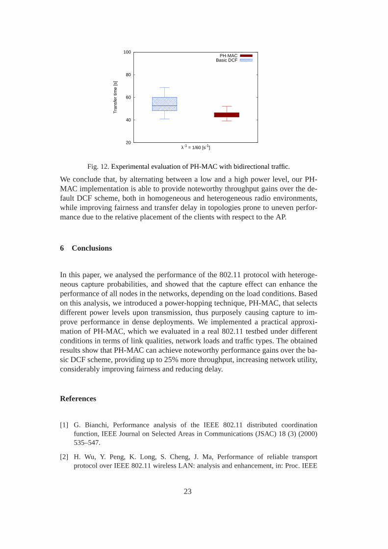
We further investigate the performance of PH-MAC under the previous scenariowith heterogeneous link qualities, this time considering anetwork with bidirec-tional traffic. Rather than fully saturating the network with synthetic traffic, ourgoal here is to understand the benefits of our proposal under representative webworkloads, that mimic the behaviour of real users.Specifically, stations establishfinite size TCP connections, alternating between periods of activity, during which a10 Mbyte file is transferred, and silent periods exponentially distributed with meanλ−1 = 60 s [32]. We run such experiments for a total time of 3 hours withboththe basic DCF mechanism and the proposed PH-MAC scheme, logging all transferdurations and computing the per-station average delay.We expect dissimilar linkconditions in combinations with existing congestion avoidance mechanisms in cur-rent TCP implementations to exacerbate unfairness. Thus oursecond goal here isto understand whether PH-MAC can improve fairness also withsuch traffic. To il-lustrate the distribution of the average delay among nodes with the two approaches,we use a box-and-whisker plot.
As depicted in Fig. 12, when employing PH-MAC stations attain reduced transferdelays as compared to the basic DCF, as the median (marked withdark line) isapproximately 10 s lower with our approach (42 s with PH-MAC, compared to52 s with basic DCF). Further, the distance between the first and third quartiles issmaller with PH-MAC, which shows that most of the stations experience similarperformance. This contrasts to the significantly differentdelays nodes attain withthe basic DCF due to dissimilar link qualities.
22
20
40
60
80
100
Tra
nsfe
r tim
e [s
]
λ-1 = 1/60 [s-1]
PH-MACBasic DCF
Fig. 12.Experimental evaluation of PH-MAC with bidirectional traffic.
We conclude that, by alternating between a low and a high power level, our PH-MAC implementation is able to provide noteworthy throughput gains over the de-fault DCF scheme, both in homogeneous and heterogeneous radio environments,while improving fairness and transfer delay in topologies prone to uneven perfor-mance due to the relative placement of the clients with respect to the AP.
6 Conclusions
In this paper, we analysed the performance of the 802.11 protocol with heteroge-neous capture probabilities, and showed that the capture effect can enhance theperformance of all nodes in the networks, depending on the load conditions. Basedon this analysis, we introduced a power-hopping technique,PH-MAC, that selectsdifferent power levels upon transmission, thus purposely causing capture to im-prove performance in dense deployments. We implemented a practical approxi-mation of PH-MAC, which we evaluated in a real 802.11 testbed under differentconditions in terms of link qualities, network loads and traffic types. The obtainedresults show that PH-MAC can achieve noteworthy performance gains over the ba-sic DCF scheme, providing up to 25% more throughput, increasing network utility,considerably improving fairness and reducing delay.
References
[1] G. Bianchi, Performance analysis of the IEEE 802.11 distributed coordinationfunction, IEEE Journal on Selected Areas in Communications (JSAC) 18 (3) (2000)535–547.
[2] H. Wu, Y. Peng, K. Long, S. Cheng, J. Ma, Performance of reliable transportprotocol over IEEE 802.11 wireless LAN: analysis and enhancement, in:Proc. IEEE
23
INFOCOM, 2002, pp. 599–607.
[3] A. Kumar, E. Altman, D. Miorandi, G. Munish, New insights from a fixed-pointanalysis of single cell IEEE 802.11 WLANs, IEEE/ACM Trans. Netw. 15 (2007) 588–601.
[4] D. Malone, K. Duffy, D. Leith, Modeling the 802.11 distributed coordination functionin nonsaturated heterogeneous conditions, IEEE/ACM Trans. Netw. 15 (1) (2007)159–172.
[5] X. Ge, D. Yan, Y. Zhu, Throughput model of IEEE 802.11 networks with captureeffect, in: Proc. IEEE WiCOM, 2006, pp. 1–4.
[6] Z. Hadzi-Velkov, B. Spasenovski, Capture effect in IEEE 802.11basic service areaunder influence of Rayleigh fading and near/far effect, in: Proc. IEEE PIMRC, Vol. 1,2002, pp. 172–176.
[7] Z. Hadzi-Velkov, B. Spasenovski, On the capacity of IEEE 802.11 DCF with capturein multipath-faded channels, International Journal of Wireless Information Networks9 (2002) 191–199.
[8] G. Sutton, R. Liu, X. Yang, I. Collings, Modelling capture effect for802.11 DCF underRayleigh fading, in: Proc. IEEE ICCC, 2010.
[9] A. Kochut, A. Vasan, A. Vasan, A. U. Shankar, A. Agrawala, Sniffing out the correctphysical layer capture model in 802.11b, 2004, pp. 252–261.
[10] J. Lee, W. Kim, S.-J. Lee, D. Jo, J. Ryu, T. Kwon, Y. Choi, An experimental study onthe capture effect in 802.11a networks, in: Proc. ACM WinTECH, Montreal, Quebec,Canada, 2007, pp. 19–26.
[11] N. Santhapuri, R. R. Choudhury, J. Manweiler, S. Nelakuduti, S.Sen, K. Munagala,Message in Message MIM: A case for reordering transmissions in wireless networks,in: Proc. HotNets, 2008.
[12] P. Patras, H. Qi, D. Malone, Exploiting the Capture Effect to ImproveWLANThroughput, in: IEEE International Symposium on a World of Wireless, Mobile andMultimedia Networks (WoWMoM), 2012.
[13] C. Lau, C. Leung, Capture models for mobile packet radio networks, in: Proc. IEEEICC, Vol. 30, 1990, pp. 1226–1230.
[14] M. Zorzi, R. Rao, Capture and retransmission control in mobile radio,IEEE Journalon Selected Areas in Communications (JSAC) 12 (8) (1994) 1289–1298.
[15] P. Serrano, A. Banchs, P. Patras, A. Azcorra, Optimal configuration of 802.11e EDCAfor real-time and data traffic, IEEE Transactions on Vehicular Technology 59 (5)(2010) 2511–2528.
[16] K. Kosek-Szott, M. Natkaniec, A. R. Pach, A simple but accurate throughput modelfor IEEE 802.11 EDCA in saturation and non-saturation conditions, Comput.Netw.55 (3) (2011) 622–635.
24
[17] F. Peng, K. Shafiee, V. C. M. Leung, Throughput Modeling of Differentiation Schemesfor IEEE 802.11e MAC Protocol, in: Proc. IEEE VTC Fall, 2012, pp. 1–5.
[18] S. Ganu, K. Ramachandran, M. Gruteser, I. Seskar, J. Deng,Methods for restoringMAC layer fairness in IEEE 802.11 networks with physical layer capture,in: Proc.REALMAN, Florence, Italy, 2006, pp. 7–14.
[19] J. Manweiler, N. Santhapuri, S. Sen, R. Roy Choudhury, S. Nelakuditi,K. Munagala, Order matters: Transmission reordering in wireless networks,IEEE/ACM Transactions on Networking 20 (2) (2012) 353 –366.
[20] D. Qiao, S. Choi, A. Jain, K. Shin, Adaptive transmit power controlin IEEE 802.11awireless LANs, in: Proc. VTC Spring, Vol. 1, 2003.
[21] V. P. Mhatre, K. Papagiannaki, F. Baccelli, Interference Mitigationthrough PowerControl in High Density 802.11 WLANs, in: Proc. IEEE INFOCOM, 2007.
[22] K. Ramachandran, R. Kokku, H. Zhang, M. Gruteser, Symphony: Synchronous Two-Phase Rate and Power Control in 802.11 WLANs, IEEE/ACM TransactionsonNetworking 18 (4) (2010) 1289–1302.
[23] IEEE 802.11 WG, Wireless LAN Medium Access Control (MAC) and Physical Layer(PHY) specifications, IEEE Std 802.11, 2007.
[24] I. Tinnirello, S. Choi, Y. Kim, Revisit of RTS/CTS exchange in high-speed IEEE802.11 networks, in: Proc. IEEE WoWMoM, 2005, pp. 240–248.
[25] I. Broustis, J. Eriksson, S. V. Krishnamurthy, M. Faloutsos, Implications of powercontrol in wireless networks: A quantitative study, in: Proc. Passive and ActiveMeasurement Conference (PAM), 2007.
[26] K. Duffy, Mean field Markov models of wireless local area networks, MarkovProcesses and Related Fields 16 (2) (2010) –.
[27] K. Huang, K. R. Duffy, D. Malone, H-RCA: 802.11 collision-aware rate control,IEEE/ACM Trans. Netw. (2012) –.
[28] K. Kowalik, M. Bykowski, B. Keegan, M. Davis, Practical issues of power control inIEEE 802.11 wireless devices, in: Proc. IEEE ICT, 2008, pp. 1–5.
[29] V. Shrivastava, D. Agrawal, A. Mishra, S. Banerjee, T. Nadeem, Understanding thelimitations of transmit power control for indoor WLANS, in: Proc. ACM IMC, SanDiego, USA, 2007.
[30] F. Kelly, Charging and rate control for elastic traffic, European Transactions onTelecommunications 8 (1) (1997) 33–37.
[31] A. Checco, D. Leith, Proportional Fairness in 802.11 Wireless LANs, IEEE CommsLetters 15 (8) (2011) 807–809.
[32] P. Barford, M. Crovella, Generating representative web workloads for network andserver performance evaluation, in: Proc. ACM SIGMETRICS, Madison, UnitedStates, 1998, pp. 151–160.
25