
BAL S 990-ba_GB.P65
240
Date of Issue: 17.11.2010 Order No.: 153 146 Operating Instructions C 9.92 H S 990
-
Upload
khangminh22 -
Category
Documents
-
view
0 -
download
0
Transcript of BAL S 990-ba_GB.P65

Date of Issue: 17.11.2010Order No.: 153 146
Operating Instructions
C 9.92 HS 990


Operating Instructions
153 146 1
S 990
ForewordWe congratulate you on having bought a product fromHOLDER. We would like you to be able to work safely withyour tractor and without malfunctions, and therefore we rec-ommend you follow the instructions in this manual. You willalso ensure getting full value from your tractor, save your-self trouble and maintain your warranty. These operating in-structions provide you with the required information. Theseoperating instructions also apply to tractors with the desig-nation 9.92 H.
Continual development
Due to the continual development of our tractor in designand equipment, there may be deviations between theseoperating instructions and your tractor.Despite taking all the care possible in the creation of thismanual, we can not fully exclude mistakes. Please notethat the technical data, illustrations and descriptions arenot binding and no legal claims can be made on the basisthereof.These operating and maintenance instructions are suppliedwith each tractor. Keep these in a safe place where they areavailable for the driver and owner at any time. It they shouldget lost, the owner must get a replacement from the manu-facturer.
The personnel entrusted with the operation and maintenanceof the tractors must be made familiar with the operating andmaintenance instructions. The owner must ensure that everyoperator has received, read and understood these instruc-tions.We thank you for reading and observing these instructions.In case you still have any questions, suggestions for im-provements or discovered mistakes, please contact ourcustomer service.
General notes on serviceOn receipt of the machine please make sure that yourHOLDER dealer will take care of the online registration.This registration is the proof in case of any warranty claims .Have the scheduled services carried out at the proper inter-vals and have them confirmed with the dealer’s stamp andsignature in these instructions. Please note that warrantycan only be claimed if the regular services have been car-ried out as scheduled.

S 990Operating Instructions
2 153 146
ForewordIn case of questions regarding your tractor, please state thefollowing data:
Tractor model ..................................................... eg S 990Engine serial number ................................... eg 10668874Chassis serial number .................................. eg 53400101Date of sale,date of complaint, if necessary .................. eg 15.07.2009Service hours ................................... eg 500 service hours
Date of issue and version of instructions
February 2010
We wish you safe driving and troublefree working with yourHOLDER.
Max Holder GmbHMax-Holder-Straße 172555 Metzingen
Phone 07123 966 - 0Fax 07123 966 - 228E-mail: [email protected]
Explanation of the cautions used:
DANGERIndicates procedures which must be observedexactly to prevent danger to the life and limbsof persons.
CAUTIONIndicates procedures which must be observedexactly to prevent personal injuries.
ATTENTIONIndicates procedures which must be observedexactly to prevent damage to and/or destruc-tion of objects and equipment.
NOTEFor technical exigencies requiring particularattention.

Operating Instructions
153 146 3
S 990Foreword
Chapter PageChapter Page
Table of contents
Foreword ........................................................................ 1
Information on the tractor .............................................. 5
Operating instructions .................................................... 7
Technical data ..............................................................15
Description ...................................................................27
Taking into service .......................................................45
Operation ......................................................................59
Special operating instructions .......................................75
Operating the attachments ...........................................79
Other operations ......................................................... 117
Parking the tractor ...................................................... 133
Trailers, towing ........................................................... 135
Transport, hoisting, towing .......................................... 139
Indicators, adjustments .............................................. 143
Malfunctions, causes, remedy .................................... 145
General remarks on maintenance ............................... 155
Maintenance schedule ................................................ 163
Maintenance during the initial period of operation ....... 169
Maintenance after the first 50 service hours ............... 169
Maintenance after the first 500 service hours ............. 181
Maintenance as required ............................................. 185
Maintenance every 250 service hours ........................ 195
Maintenance every 500 service hours ........................ 203
Maintenance every 1000 service hours ....................... 205
Maintenance every 1500 service hours ....................... 207
Maintenance every 3000 service hours ....................... 209
Annual maintenance ................................................... 211
Maintenance every 2 years......................................... 215
Maintenance every 5 years......................................... 217
Taking the tractor out of operation .............................. 219
Coolant, fuel and lubricant specifications ................... 221
Maintenance data ....................................................... 223
Alphabetical index ...................................................... 229


Operating Instructions
153 146 5
S 990
Information on the tractorThis tractor has received the type approval acc. to 2003/37/EC after a safety inspection. Furthermore, the vehicle com-plies with the pertinent safety and health requirements ofEC directive 2006/42/EG which are not covered by direc-tive 2003/37/EC. The tractor conforms to the EMC (Electro-magnetic Compatibility) requirements of directive 2009/64/EC. The regulations for exhaust gas identification and noiseemissions are observed. The tractor must be registered andthe licence plates must be attached at the front and rear.
Intended useThe tractor can be used for towing trailers and for the opera-tion of various attachments. The maximum trailer load, whichmust not be exceeded, is stated on the identification plate.The transport of persons is not allowed.The tractor is designed solely for the customary type ofoperation in farming and forestry, the upkeep of municipalfacilities, including operation in winter. The tractor may onlybe used as intended and described in these operating in-structions.Included in the intended use is also the performance of thespecified maintenance and repairs.
The tractor, together with its attachments, may only be used,serviced and repaired by persons familiar with this equip-ment and who have been warned of possible risks. The ap-plicable safety regulations and any other valid safety, in-dustrial medicine and traffic rules must be observed.
Site of operation
The tractor must be used in the open. Its operation on publicroads is allowed. When using the tractor on public roads,observe the regulations in your country.
Unintended use
Any use which is not intended as described above is notallowed. HOLDER can not be held responsible for any haz-ards which may result from any unintended use. The manu-facturer will not be responsible for any damage which mayresult therefrom. The damage shall solely be borne by theuser. The tractor may not be used for any other purposesthan those described in these instructions. The transport ofpersons on the loading area or attachment is not allowed.

S 990Operating Instructions
6 153 146
Information on the tractorResidual hazards and risks
Despite careful working and conformance with standards andregulations, hazards arising from handling the tractor can notbe excluded.The tractor and all other system components conform tocurrently applicable safety regulations. A residual risk, how-ever, can not be excluded even if the tractor is used asintended and all the safety notices given are observed.For this reason, persons standing in the area of the tractorand attachments must exercise particular caution in orderto be able to react immediately in case of a malfunction,incident, failure, etc.
CAUTIONAll persons standing in the area of the tractorand attachments must be advised of the riskswhich can result from their operation. Alsoread and observe the other safety rules andregulations contained in these operating in-structions.
The hazards can include:- Unexpected movements the attachments and of the
tractor.- Escape of fuel, fluids and lubricants due to leaks,
broken lines and containers, etc.- Risk of accidents when driving, steering and braking
due to unfavourable ground conditions such asslopes, icy roads, unevenness or poor visibility, etc.
- Falling, stumbling, etc when moving on the tractor,particularly if it is wet.
- Risk of fires and explosions due to the battery andelectric voltages.
- Danger of poisoning through diesel exhaust fumes.- Risk of fire through diesel fuel and oils.- Human misconduct through the non-observance of
safety rules.
Disposal instructions
Your tractor is made of different materials. Each materialshould be disposed of/treated/recycled according to differ-ent regional/national regulations. We recommend contact-ing a salvage company.

Operating Instructions
153 146 7
S 990
Operating instructions
Driver’s licence
For the driving of this tractor you require a driver’s licencedepending on the maximum ground speed and the permissi-ble total weight of the tractor and combinations. See thetables below.
Driver’s licence classes
Tractors for farming and forestry (also with attachments)
Top speed(design-dependent)
Maximum total weight Driver's licence class(minimum requirement)
Previous driver'slicence class
Up to 32 km/h No limitation B, L, T 1, 1a, 1b, 2, 3, 4, 5
Up to 3.5 t BT: up to 60 km/h,under 18 years onlyup to 40 km/h
2, 3Over 32 km/h
Over 3.5 tto 7.5 t
C1T: up to 60 km/h,under 18 years onlyup to 40 km/h
2, 3

S 990Operating Instructions
8 153 146
Operating instructionsSingle-axle trailers or two-axle trailers with axle base of up to 1 metre maximum
25
25
25
25
Maximum total weightDriver's licence class(minimum requirement)
Previous driver'slicence class
Trailer weight up to 750 kg B, C1, C, T 1, 1a, 1b, 2, 3, 4, 5
L: only with additional signand type-dependent maximumtractor ground speed of 25 km/h
Trailer weight over 750 kg BE, C1E, CE, T 1, 1a, 1b, 2, 3, 4, 5
B, C1, C: only up to 3.5 t of max.total combined weight and max.total trailer weight ≤ curb weightof tractor; otherwise:
C1E: only up to 12 t max. totalcombined weight and max. totaltrailer weight ≤ curb weight oftractor; otherwise:
L:

Operating Instructions
153 146 9
S 990Operating instructions
Multiple-axle trailers and two-axle trailers with an axle base over 1 metre
25
25
25
25
25
Maximum total weightDriver's licence class(minimum requirement)
Previous driver'slicence class
Trailer weight up to 750 kg B, C1, C, T 2, 3
L: only with additional signand type-dependent maximumtractor ground speed of 25 km/h
Trailer weight over 750 kg BE, C1E, CE, T 2, 3
Up to 3.5 t max. total weight B, C1, C: only up to 3.5 t of max.total combined weight and max.total trailer weight ≤ curb weightof tractor; otherwise:
1, 1a, 1b, 4, 5:each
Up to 12 t max. total weight C1E: only up to 12 t max. totalcombined weight and max. totaltrailer weight ≤ curb weight oftractor; otherwise:
L:

S 990Operating Instructions
10 153 146
Operating instructionsTwo trailers behind tractors for farming and forestry
25
25
25
25
Maximum total weightDriver's licence class(minimum requirement)
Previous driver's licenceclass
BE, C1E, CE, T 2, 3
Up to 3.5 t max. total weight B, C1, C:only up to 3.5 t of max. totalweight of the combinationand max. total weight of thetrailer ≤ curb weight oftractor; otherwise:
1, 1a, 1b, 4, 5,
Up to 12 t max. total weight C1E:only up to 12 t max. totalweight of the combinationand max. total weight of thetrailer ≤ curb weight oftractor; otherwise:
L:

Operating Instructions
153 146 11
S 990Operating instructions
Safety
General notes on safety
• Observe your national regulations for safety andhealth protection.
• Do not allow children under 16 to use the tractor.• When using the public highway, respect the highway
code.• Do not allow anyone to stand around where they might
get hurt.• Do not run the engine in enclosed spaces.• Exercise extreme caution when handling fuels. There
is a high risk of fire.• Exercise extreme caution when handling fuel, fluids
and lubricants. These can be poisonous and corro-sive.
• To prevent the danger of fire, keep the tractor andattachments clean.
• Observe the warning notices and symbols on yourtractor.
• Emergency stop When the inching pedal or tractionhydraulics is defective, the tractor can only bebrought to a halt by setting the ignition to 0 and usingthe service brake.
Working clothes
• Only wear snugly fitting clothing when working withthe tractor.
• If necessary, wear suitable headwear to keep loosehairs and pigtails from being caught in rotating parts.
• Do not wear jewellery and similar objects, eg rings,when working with the tractor.
Safety notes for retrofits
The tractor has electronic components whose proper func-tioning can be influenced by electromagnetic emissions fromother equipment. These influences can endanger persons ifthe following notes on safety are not observed.• Have the equipment installed by your service centre
only.• Before the installation of electric or electronic equip-
ment connected to the tractor’s electrical system,check if these installations can interfere with thetractor’s electronic system or other system compo-nents.

S 990Operating Instructions
12 153 146
Operating instructions• The installed equipment must conform to the applica-
ble EMC directive 2009/94/EC and carry the CEsymbol.
• If you must install a mobile communications system(or have it installed) (eg radio, mobile telephone), thefollowing requirements must be met:
- Only approved equipment (eg with type approval) maybe installed.
- The equipment must be installed permanently,- The operation of portable or mobile equipment inside
the tractor is only allowed if connected to a perma-nently installed external antenna,
- The transmitting section must be installed away fromthe tractor’s electronic system.
- When installing the antenna, install it properly andwith a good connection to tractor ground.
- Do not exceed the maximum permissible currentrating of the wiring according to the installation in-structions of the equipment manufacturer.
- Before doing electric welding, disconnect all plugsfrom the electronics.
Safety instructions for handling fuel, fluidsand lubricants
Gear oil, engine oil, diesel fuel
Do not eat, drink or smoke when handlingthese fuel, fluids and lubricants. Prolongedintensive contact may cause degreasing andirritation of the skin. Wash the skin with waterand soap; use a skin care cream. If neces-sary, wear personal protective gear. Changesoaked clothes and shoes immediately. Ifvapour or mist was inhaled, breathe fresh air.Consult a doctor if the complaint persists.After contact with the eyes, rinse the eyesthoroughly with water (at least 10 minutes),then consult an eye doctor. If swallowed, donot force to vomit, but consult a doctor. Dan-ger of slipping on the spilled product, particu-larly in connection with water.Oils can contaminate water. Always keep themin approved containers. Avoid spilling fluids.Remove spilled fluids immediately with an oilbinding agent and discard in accordance withlaws and regulations. Discard old fluids as speci-fied.

Operating Instructions
153 146 13
S 990Operating instructions
Observe applicable laws and regulations. Oilsare inflammable. Do not let them come incontact with hot engine parts as fire can re-sult.
Hydraulic oil, brake fluid
During tractor operation, these fluids are pres-surized and pose a health hazard. Do not spillthese fluids. Remove any spilled fluids imme-diately with an oil binding agent and discardthem as specified. Discard the old fluid as speci-fied. Observe applicable laws and regulations.Do not allow them to come in contact with hotengine parts. Danger of fire!Avoid contact with the skin. Avoid the inhala-tion of spray fog. The penetration of pressu-rized fluids into the skin is particularly danger-ous if these fluids are under high pressure andescape from the hydraulic system throughleaks. Seek medical aid at once in case of suchinjuries.If injuries can not be excluded, use a suitablepersonal protector (for example, protectivegloves, glasses and skin protection and skincare creams).
Battery acid
Battery acid contains dissolved sulphuricacid. This acid is poisonous and caustic. Whenworking with battery acid, always wear pro-tective clothing and eye protectors. Do notallow acid to contact the clothing, skin or eyes;in case of contact wash immediately withample clean water. In case of personal inju-ries, consult a doctor at once. Neutralizespilled battery acid immediately.Discard old fluids as specified. Observe ap-plicable laws and regulations.
Emissions
Exhaust Gases
During operation, the engine emits exhaustgas into the environment. The exhaust gasmainly consists of water vapour, carbon di-oxide (CO2), carbon monoxide (CO), carbonhydride (CH), nitrogen oxide (NOX) and soot.The components CO, CH and NOX are poi-sonous or hazardous to health and shouldnot be inhaled in high concentrations. Soot isa carcinogenic material.
S 990Operating Instructions
14 153 146
Operating instructionsParticularly the particulates contained in theexhaust gas can cause cancer. For this rea-son the engine should not be operated in en-closed spaces.
Heat
The exhaust gases are very hot and can ig-nite inflammable material. Therefore keep theexhaust pipe away from inflammable materi-als.
Battery
During charging the battery emits a mix ofoxygen and hydrogen (detonating gas). Thisgas mix is explosive and must not be ignited.The danger of explosion can be avoided withsuitable ventilation and the keeping nakedfires away. Observe the safety rules whenhandling the battery.

Operating Instructions
153 146 15
S 990
Technical data
Tractor dimensions
Dimensional drawing

S 990Operating Instructions
16 153 146
Technical dataTable of dimensions for S 990
Tow coupling
Tires Type Profile Totalheight
Avg.seatheight
Groundclearance
Lowestposition
Highestposition
Dumpbodyheight
PTO height
amm
bmm
cmm
dmm
dmm
gmm
hmm
imm
280/80 R18280/80 R18 S
532-31-08532-31-09 XMCL 2243 1265 227 572 972 1136 481 327
36x13.50-15 524-31-8 Multi Trac 2236 1258 220 565 965 1129 474 320
10.5-18 MPT10.5-18 MPT S
524-31-1524-31-6 AT 603 2233 1255 217 562 962 1126 471 317
425/55 R17 532-31-02 AC 70G 2227 1249 211 556 956 1120 465 311
425/55 R17 532-31-01 All – Ground 2221 1243 205 550 950 1114 459 305
400/60-15.5 524-31-5 404 2212 1234 196 541 941 1105 450 296
33x12.50-R15 524-31-7 Discoverer LT 2209 1231 193 538 938 1102 447 293
33/18LL-16.1 524-31-9 Turf Special 2209 1231 193 538 938 1102 447 293
33x12.50-15 524-31-4 413 TL 2194 1216 178 523 923 1087 432 278
33x15.50-15 524-31-3 412 TL 2193 1215 177 522 922 1086 431 277
31x15.50-15 524-31-2 Xtra Trac 2181 1203 165 510 910 1074 419 265

Operating Instructions
153 146 17
S 990Technical data
Distance between centreline of tires
With hub spacersNormal track width(flange size 1034)
Type 5234-80 = 45 mm Type 526-34-70 = 80 mm
Track width e Overall width f Track width e Overall width f Track width e Overall width fTires
Small turningradiusto DIN 7020at min. trackwidth(measured atoutermost pointof truck)
Min.-mm
Max.-mm
Min.-mm
Max.-mm
Min.-mm
Max.-mm
Min.-mm
Max.-mm
Min.-mm
Max.-mm
Min.-mm
Max.-mm
10.5-18 MPT S 7.12 m 960 1124 1234 1398 1050 1214 1324 1488 1120 1284 1394 1558
33x12.50-15 7.19 m 1000 1084 1310 1394 1090 1174 1400 1484 1160 1244 1470 1554
10.5-18 MPT 7.19 m 1034 1052 1308 1326 1124 1142 1398 1416 1194 1212 1468 1486
280/80 R18 7.21 m 1034 1052 1324 1342 1124 1142 1414 1432 1194 1212 1484 1502
33x12.50R15 7.30 m - 1084 - 1427 1090 1174 1433 1517 1160 1244 1503 1587
36x13.50-15 7.35 m - 1084 - 1465 1090 1174 1471 1555 1160 1244 1541 1625
400/60-15.5 7.38 m - 1104 - 1504 - 1194 - 1594 1142 1264 1542 1664
425/55 R17 7.42 m - 1114 - 1545 - 1204 - 1635 - 1274 - 1705
280/80 R18 S 7.30 m - 1124 - 1414 1050 1214 1340 1504 1120 1284 1410 1574
31x15.50-15 7.39 m - 1124 - 1518 - 1214 - 1608 1122 1284 1516 1678
33x15.50-15 7.39 m - 1124 - 1519 - 1214 - 1609 1122 1284 1517 1679
33/18LL-16.1 7.51 m - 1164 - 1639 - 1254 - 1729 - - - -

S 990Operating Instructions
18 153 146
Technical dataWeights
Weight in kg
Max. curb weight 4500 kg
Max. front axle load *2660 kg - 2700 kg
Max. rear axle load *2660 kg - 3000 kg
Max. tongue weight on tow coupling 800 kg
* With 33X12.50 R15 tires
Auxiliary assemblies Total Front Rear
Inching speed 13 kg 10 kg 3 kg
Rear lift 77 kg -25 kg 102 kg
Dump body 75 kg 0 kg 75 kg
Tires33x12,50-15 33x12,50R15
31x15,50-15
33x15.50-15
10,5-18MPT
36x13.50-15400/60-15.5 33/18LL-16.1 280/80 R18 425/55 R17
Curb weightS 990(with driver75 kg)
Total: kg 2638 2648 2668 2696 2718 2734 2766 2790
Front kg 1220 1225 1235 1249 1260 1268 1284 1296
Rear kg 1418 1423 1433 1447 1458 1466 1482 1494

Operating Instructions
153 146 19
S 990Technical data
Tires
Note: Observe the max. tire inflation pressure (max. loading) for the max. axle load and for road travel.Adjust the inflation pressure acc. to the data of the tire manufacturer for max. tractive force for off road travel andto reduce the ground pressure.
The pressure can deviate, depending upon the make and use of the tires. Observe the instructions of the tiremanufacturer.
Type of tyre Capacity Profile Tube Inflation pressure (in bar) Wheel ballast weights
Curb weight Max. loading Type Weight
Front Rear
280/80 R18 132A8 XMCL No 1.6 2.5 2.5 524-34-1 ca. 45 kg
36x13.50-15 114B / 4PR Multi Trac No 1.0 1.2 1.4 524-34-1 ca. 45 kg
10.5-18 MPT 10 AT 603 Yes 2.2 2.2 2.2 524-34-1 ca. 45 kg
425/55 R17 134G AC 70G No 0.8 1.6 1.6 524-34-1 ca. 45 kg
425/55 R17 134G All - Ground No 0.8 1.6 1.6 524-34-1 ca. 45 kg
400/60-15.5 132A8 404 Yes 1.8 1.8 2.0 524-34-1 ca. 45 kg
33x12.50-15 6PR 413 TL No 1.4 1.9 2.0 524-34-1 ca. 45 kg
33x12.50 R15 108Q Discoverer LT No 1.6 2.5 2.5 524-34-1 ca. 45 kg
33x15.50-15 6PR 412 TL No 1.0 1.6 1.6 524-34-1 ca. 45 kg
33/18LL-16.1 10PR Turf Special No 1.2 1.8 2.0 - -
31x15.50-15 115B Xtra Trac No 2.0 3.2 3.2 524-34-1 ca. 45 kg

S 990Operating Instructions
20 153 146
Technical dataEngine specifications
S 990
Manufacturer Deutz AG
Model designation TD2011 L04w
Engine type 4-stroke diesel
No. of cylinders 4
Cubic capacity 3619 cm³
Specific fuel consumption 216 g/kWh
Rated speed 2600 rpm
Upper idle speed 2600 rpm +200 rpm
Lower idle speed 900-950 rpm
Power to 97/68 ECn=2600 rpm
68.0 kW (92 HP)

Operating Instructions
153 146 21
S 990Technical data
Theoretical ground speeds
Transmission
Engine output 68 kWEngine speed 2600 RPM
Hydrostaticdrive
Dual Drive30 km/h
Dual Drive40 km/h
Tires Type Unit
280/80 R18 532-31-08/09 km/h 31.3 32.3 39.1
36x13.50-15 524-31-8 km/h 31.1 32.1 38.8
10.5-18MPT 524-31-1/-6 km/h 30.8 31.7 38.4
425/55 R17 532-31-01/-02 km/h 29.8 30.7 37.2
400/60-15.5 524-31-5 km/h 29.7 30.7 37.1
33x12.50-15 524-31-4 km/h 29.4 30.3 36.7
33x12.50R15 524-31-7 km/h 29.2 30.1 36.4
33x15.50-15 524-31-3 km/h 28.8 29.7 35.9
33/18LL-16.1 524-31-9 km/h 28.8 29.7 35.9
31x15.50-15 524-31-2 km/h 26.5 27.3 33.0

S 990Operating Instructions
22 153 146
Technical dataTechnical data /filling quantities
Assembly Additionalinformation
Description
Hydrostatic drive Infinitely variable ground speed, 2 mechanical speed ranges
PTO shafts 2 PTOs (front and rear), sense of rotation: clockwise when lookingon shaft end
- RPM at front 540 RPM at 2200 engine RPM, 1000 RPM at 2390 engine RPM
- RPM at rear 1000 RPM at 2360 engine RPM
- Spline profile 1 3/8’’ (6) DIN 9611
PTO clutch Wet multi-disc clutch, electro-hydraulically operated
Differential lock Simultaneous front and rear operation, electro-hydraulically operated
Fuel system
Fuel tank Diesel fuel 82 litres

Operating Instructions
153 146 23
S 990Technical data
Assembly Additionalinformation
Description
Steering
- Type Hydrostatic with 2 double-acting steer cylinders
- Steering valve Orbitrol OSPC 125 LS (single-stage) or OSPD 125/205 (two-stage)
Brakes
- Service brake Multi-disc brake, wet, acting on all 4 wheels
- Actuator Hydraulic
- Parking brake Multi-disc brake, wet, acting on all 4 wheels
- Operation Electrically-operated
Tow coupling
- Type Cramer, height-adjustable
Front lift
- Type 3-point, upper link adjustable
- Attachment Category I and II
- Lifting power 2700 N (measured at attachment points)
- Cylinder 2 cylinders, double-acting

S 990Operating Instructions
24 153 146
Technical dataAssembly Additional information Description
Rear lift
- Type HOLDER standard 3-point
- Attachment Category I and II
- Lifting power 15700 N (measured at attachment points)
- Cylinder 2 cylinders, double-acting
Dump body
- Dimensions L X W X H 1530 x 1140 x 215 mm
- Load capacity 1300 kg
Traction hydraulics
Variable pump Hydromatik
- Type A4 VG 40 EP
- Output 160 litres/min
- Operating pressure 380 bar (430 bar maximum)
Variable motor Hydromatik
- Type A6 VM 55 EP
- Displacement 26.1 - 55 cm3/rev
Hydraulic oil tank 45 L (common oil tank for traction and working hydraulics)

Operating Instructions
153 146 25
S 990Technical data
Assembly Additionalinformation
Description
Working hydraulics (withsteering)
Pump Sauer-Sundstrand
- Type -
- Output 17 cm3/rev (42.5 L/min at 2500 engine RPM)
- Operating pressure 180-190 bar
Hydraulic oil tank 45 L (common oil tank for traction and workinghydraulics)
Electrical system
- Operating voltage 12 VDC
- Battery 12 V / 100 Ah
- Alternator 12 V / 95 A
- Starter motor 12 V / 2.4 kW
General tractor
- Operating range - 30°C to + 50°C

S 990Operating Instructions
26 153 146
Technical dataNoise level
The tractor emits the following noise level (measured at thedriver’s ear) according to EU Standard 77/311/EEC; meas-urement according to Appendix II.
Table of noise levels and absorption rating
Exhaust gas identification
The absorption rating is stated on the type plate.
Model Type ofengine
Engine output Noise level dB(A) Absorption value
Cabin open* Cabin closed
Left Right Left Right
S 990 TD2011 L04w 68.0 kW (92 HP) 85 85 84 84 1.3
*Roof hatch and side window open

Operating Instructions
153 146 27
S 990
Description
Views of vehicle
Front left view1 Turn signal and
position light2 Top headlight3 Driver’s cab4 Dumping subframe
(dumping device)5 Rear end of tractor6 Rear axle7 Front axle8 Upper link bracket9 Lower link frame
of front lift10 Headlight11 Plug-in hydraulic
quick couplings forattachments*
12 Wiper/washer
1 2 3 4
5
6
78
9
10
12
11
Bild_S 990_010

S 990Operating Instructions
28 153 146
DescriptionTractor
Rear right view
1 Dumping subframe2 Working light*3 Mount for
top strobe warninglight*
4 Driver’s cab5 Front end of tractor6 Front axle7 Intake screen of
fresh air fan8 Engine air intake9 Hydraulic oil filler
neck10 Fuel filler neck11 Rear axle12 Plug-in hydraulic
quick couplings forattachment*
13 Lower link frameof rear lift*
14 Tail light, left/right15 Trailer coupling
* Option
2 3 4 5
6
79111213
1
15
Bild_S 990_011810
14

Operating Instructions
153 146 29
S 990Description
Driver’s station
Operating controls
1 Direction lever2 Lever for left side window3 Steering wheel4 Multifunctional display5 Lever for right side window6 Turn signal and wiper lever7 Toggle switch for meter
(ground speed in km/h or PTO RPM)8 Ignition lock9 Toggle switch for top headlight
10 Light switch11 Accelerator pedal12 Brake pedal13 Preheating indicator14 Speed range selector15 Inching pedal16 Parking brake switch17 Switch for two-stage steering*18 Toggle switch for console or steering column direc-
tion switch
* Option
1
2
3 4
5
109
8
6
1112
16
17
18
Bild_S 990_00115 1314
7
S 990Operating Instructions
30 153 146
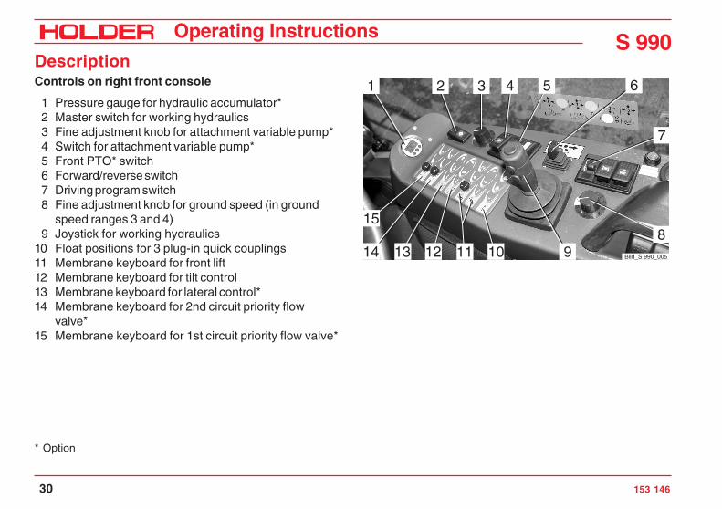
DescriptionControls on right front console
1 Pressure gauge for hydraulic accumulator*2 Master switch for working hydraulics3 Fine adjustment knob for attachment variable pump*4 Switch for attachment variable pump*5 Front PTO* switch6 Forward/reverse switch7 Driving program switch8 Fine adjustment knob for ground speed (in ground
speed ranges 3 and 4)9 Joystick for working hydraulics
10 Float positions for 3 plug-in quick couplings11 Membrane keyboard for front lift12 Membrane keyboard for tilt control13 Membrane keyboard for lateral control*14 Membrane keyboard for 2nd circuit priority flow
valve*15 Membrane keyboard for 1st circuit priority flow valve*
* Option
4 5 6
7
121314
158
91011
2 31
Bild_S 990_005
Operating Instructions
153 146 31
S 990Description
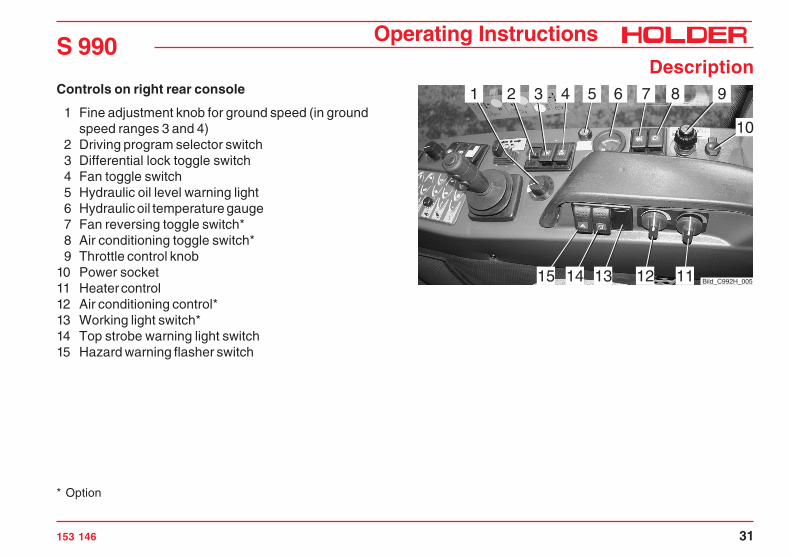
Controls on right rear console
1 Fine adjustment knob for ground speed (in groundspeed ranges 3 and 4)
2 Driving program selector switch3 Differential lock toggle switch4 Fan toggle switch5 Hydraulic oil level warning light6 Hydraulic oil temperature gauge7 Fan reversing toggle switch*8 Air conditioning toggle switch*9 Throttle control knob
10 Power socket11 Heater control12 Air conditioning control*13 Working light switch*14 Top strobe warning light switch15 Hazard warning flasher switch
* Option
64 5 7 8 9
10
15 1314 1112
321
Bild_C992H_005

S 990Operating Instructions
32 153 146
DescriptionControls on rear console
15 Diagnostic socket for working hydraulics16 Diagnostic socket for traction hydraulics17 Traction electronics trouble diode
Hand throttle
1 Outer ring for fine control:- Turn clockwise for RPM reduction- Turn counter-clockwise for RPM increase
2 Inner knob for coarse control- Pull up for RPM increase- Push down for RPM reduction- Push down fast for emergency reset to idle speed
1 2
Bild_C992H_006
171615
Bild_S 990_012

Operating Instructions
153 146 33
S 990Description
Joystick
1 Pushbutton 1 for joystick level 12 Pushbutton 2 for joystick level 23 Pushbutton 3 for joystick level 34 Joystick (with no button pressed = joystick level 0)
Pedals
1 Inching pedal2 Brake pedal3 Accelerator pedal
43
1
2
Bild_C992H_007
2 31
Bild_C992H_008

S 990Operating Instructions
34 153 146
DescriptionSteering column adjustment
1 Brake fluid reservoir2 Steering column adjustment lever
1
2 Bild_C992H_009

Operating Instructions
153 146 35
S 990Description
Km/h 0000000 h
25
1520
5
10
30
RPMx100
electronic0
Motor
digital system
1
2
6 5 478910
11
12
13
14
15 16 1 2 3
Bild_C992H_071
Multifunctional display, legend
1 Fuel gauge2 Engine oil temperature
gauge3 Tachometer with marks
for PTO RPM4 Hour meter5 Digital speedometer
Indicator lights:6 Turn signal indicator7 Turn signal indicator for
2nd trailer8 Turn signal indicator for
1st trailer9 High beam
10 Low beam11 Engine oil temperature12 Preheating13 Engine oil pressure14 Battery15 Parking brake16 Differential lock

S 990Operating Instructions
36 153 146
DescriptionControls at front top of cabin
1 Dome light2 Loudspeaker
Controls at front bottom of cabin
1 Wiper fluid reservoir2 Radio
1 2
Bild_C149
1
2 Bild_C282

Operating Instructions
153 146 37
S 990Description
Controls at rear of cabin
1 Roof hatch handle2 Roof hatch
Door controls
1 Door opener1
Bild_C156
2
1
Bild_C263

S 990Operating Instructions
38 153 146
DescriptionLocation of plates andlabels
Identification plates
1 Engine type plate2 Variable motor type plate3 Variable pump type plate4 Cabin type plate5 Chassis serial number
(on front support on right side)6 Machine type plate
(on front support)

Operating Instructions
153 146 39
S 990Description
Mounting instructions for licence plate
- Install the front licence plate (1) on the cover belowthe windshield wipers.Remove the cover before installing the licence plate.
- Install the rear licence plate (2) at the rear below theleft tail light.
2
1
Bild_C992H_010

S 990Operating Instructions
40 153 146
DescriptionOverview of options and variants (selection)
Assembly Additional information Dimension/orderno./type
Activated carbon filter for cabin ventilation 131667
Heating element for oil preheating (engine) From –20°C (230VAC) 5234-69
Air conditioning 534-34-80
Seat heater 204-34-83
Lap seat belt 204-34-81
Comfort backrest extension 204-34-80
Left armrest 204-34-82
Rear working light 204-34-88
Hydraulic lateral control For front lift 204-01-01
Rear lift 534-51-04
Mounting For ball-type hitch 526-51-73
Ball-type hitch 526-51-74
Top strobe warning light 526-34-74

Operating Instructions
153 146 41
S 990Description
Assembly Additional information Dimension/orderno./type
Electro-hydraulic accumulator 204-80-19
Circuit 1 priority flow valve 204-80-04
- Hydraulic pump Series pump
- Output 17 cm³/rev
- Flow rate 0-25 litres/min
- Maximum pressure 200 bar
Circuit 2 priority flow valve 534-80-25
- Hydraulic pump Tandem pump
- Output 14 cm³/rev
- Flow rate 0-25 litres/min
- Maximum pressure 200 bar

S 990Operating Instructions
42 153 146
DescriptionAssembly Additional information Dimension/order
no./type
Attachment variable pump 0-120 litres/min adjustable 534-80-30
- Hydraulic pump A11VO40EP
- Output 0-40 cm³/rev
- Flow rate 0-120 litres/min
- Maximum pressure 280 bar
Attachment encoding wiring harness For attachment variable pump 204-80-72
Power hydraulic system 80 litres/min fixed 534-80-35
- Hydraulic pump Mounted on traction pump Gear pump
- Output 22 cm³/rev
- Flow rate 80 litres/min
- Maximum pressure 210 bar

Operating Instructions
153 146 43
S 990Description
Accessories
The tractor is delivered with the following accessories:
Operating instructions
Folder
2 ignition keys
2 door keys
2 tank cap keys
2 reducer sleeves for Category I attachments
Upper link with retaining pins
Key folder
Bio pass for proof of filling environment-friendly hydraulicoil
Service Booklet
Spare Parts List on CD-ROM
Deutz Operating Instructions
Deutz Spare Parts List


Operating Instructions
153 146 45
S 990
Taking into service
Daily checks and activities prior to takinginto service
If damages or defects are found during the following checks,they must be eliminated before taking the tractor into serv-ice. Do not operate the tractor before proper repairs are car-ried out. Safety and protective devices should not be re-moved or disabled. Do not change fixed specified settings.Before starting work, make yourself truck familiar with allthe functions and protective devices of the tractor.
Checking/cleaning the radiator and protection screens
NOTE- Check that the protection screens (2 and
3) are clean.- Clean the screens if necessary.
The screen (3) can be pulled off to the leftafter loosening the bayonet screw (4) andthen easily cleaned.
- The air intake of the air filter (1) must beclean.
Bild_S 990_0064
3
3
2
1
Bild_C992H_011

S 990Operating Instructions
46 153 146
Taking into serviceTurning on the battery isolating switch
NOTEThe battery can be switched off fully with theremovable key.
- Insert the key (1) into the battery isolating switch andset it to the horizontal position.The battery circuit is turned on.
Checking the engine oil level
NOTECheck the engine oil level only when the ve-hicle is parked on level ground.
- Let the engine run for approx. 2 minutes.- Stop the engine and pull out the oil dipstick (1) after
approx. 1 minute.- The oil level must be between the Min and Max marks.- Top up oil as specified in the maintenance instructions.
ATTENTIONDo not fill too much oil.
1
Bild_C992H_014
Bild_C992H_0151

Operating Instructions
153 146 47
S 990Taking into service
Checking the trailer coupling (optional) if necessary
- Check the trailer coupling for proper condition andoperation. Carry out the check according to theinstructions in the section „Operating the trailercoupling“.
Checking the tire inflation pressure
NOTEYour tractor can be equipped with differenttypes of tyres. The specified inflation pres-sure for your tires is given in the table enti-tled „Tires“ in the technical data section.
- Check the inflation pressure an all four tires. All tires musthave the same pressure. Low pressure will increase therolling resistance. This will cause increased fuel con-sumption and tire wear, and the driving characteristics willbecome poorer.
DANGERIf the inflation pressure is too high, the tirescan explode!
- The tires should not be damaged or worn.- Have damaged tires replaced without delay. Due to the
longer braking distance, the risk of an accident will behigher. Bild_S 990_014
Bild_S 990_015

S 990Operating Instructions
48 153 146
Taking into serviceChecking the hydraulic oil level
- Retract all hydraulic cylinders.- Check the oil level at the sight glass (2).- The oil level must be at the centre (1) of the sight
glass.- Top up oil through the filler neck (3) as specified in
the maintenance manual.
Bild_S 990_016
31 2

Operating Instructions
153 146 49
S 990Taking into service
Filling fuel
- If necessary, read the fuel level (1) on the multifunc-tional display.
CAUTIONDanger of fire when handling fuels. Stop theengine. Do not fill fuel in the vicinity of nakedflames, ignition sparks or hot engine parts.Do not smoke when refuelling.
- Remove the fuel tank filler cap (2).- Top up diesel fuel as recommended in the mainte-
nance instructions.
Filling quantity ............................................. approx. 82 L
- Refit the filler cap (2).
2
Bild_C992H_016
Km/h 0000000 h
25
1520
5
10
30
RPMx100
electronic0
Motor
digital system
1
2
1
Bild_C992H_073

S 990Operating Instructions
50 153 146
Taking into serviceChecking the brake fluid level
- Check the level at the brake fluid reservoir (1).- The brake fluid level fluid level must between the Min
and Max marks on the reservoir.- Top up brake fluid as specified in the maintenance
instructions.
Adjusting the steering wheel
NOTEThe inclination and height of the steeringwheel can be set to a comfortable position.
DANGERDo not adjust the steering wheel while driv-ing.
- Loosen the lever (2).- Adjust the tilt and height of the steering wheel (3).- Retighten the lever (2).
Bild_C992H_017
1 2
Bild_C992H_018
3
2
Operating Instructions
153 146 51
S 990Taking into service
1 2
3456Bild_010
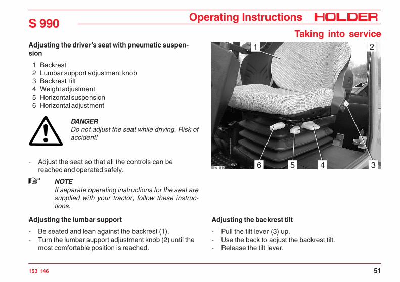
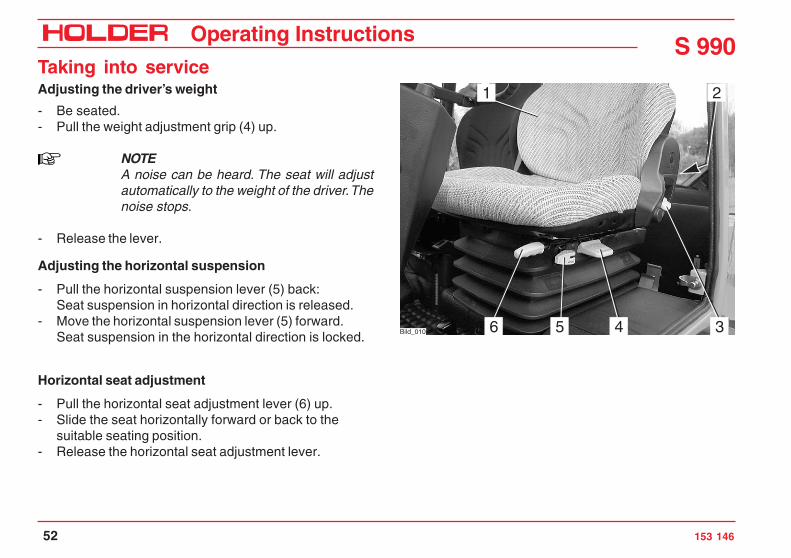
Adjusting the driver’s seat with pneumatic suspen-sion
1 Backrest2 Lumbar support adjustment knob3 Backrest tilt4 Weight adjustment5 Horizontal suspension6 Horizontal adjustment
DANGERDo not adjust the seat while driving. Risk ofaccident!
- Adjust the seat so that all the controls can bereached and operated safely.
NOTEIf separate operating instructions for the seat aresupplied with your tractor, follow these instruc-tions.
Adjusting the lumbar support
- Be seated and lean against the backrest (1).- Turn the lumbar support adjustment knob (2) until the
most comfortable position is reached.
Adjusting the backrest tilt
- Pull the tilt lever (3) up.- Use the back to adjust the backrest tilt.- Release the tilt lever.
S 990Operating Instructions
52 153 146
Taking into serviceAdjusting the driver’s weight
- Be seated.- Pull the weight adjustment grip (4) up.
NOTEA noise can be heard. The seat will adjustautomatically to the weight of the driver. Thenoise stops.
- Release the lever.
Adjusting the horizontal suspension
- Pull the horizontal suspension lever (5) back:Seat suspension in horizontal direction is released.
- Move the horizontal suspension lever (5) forward.Seat suspension in the horizontal direction is locked.
Horizontal seat adjustment
- Pull the horizontal seat adjustment lever (6) up.- Slide the seat horizontally forward or back to the
suitable seating position.- Release the horizontal seat adjustment lever.
1 2
3456Bild_010

Operating Instructions
153 146 53
S 990Taking into service
Topping up wiper water
NOTEThe washer water reservoir for the windshieldwasher system is located at the front left inthe footwell of the cabin.
- Open the filler cap (1) and top up washing water in thereservoir (2).
Filling capacity .......................................... approx. 1.3 L
Checking the lights and rear view mirror
- Check the lights for proper operation. Carry out thecheck according to the instructions in the sectionentitled „Lights“.
- Adjust the rear view mirror so that the roadway behindthe tractor and the working area can be seen well.
Bild_S 990_014
Bild_S 990_017
21

S 990Operating Instructions
54 153 146
Taking into serviceStarting the engine
Engine instructions before operation
DANGERDo not start or run the engine in enclosedspaces. Danger of poisoning through exhaustgases!
Starting instructions
CAUTIONBefore starting, make sure no-one is in thevicinity of the tractor.
ATTENTIONDo not use a starting aid such as a start pilotor similar means. Turn off the traction drive orany driven attachments.
CAUTIONStart the engine only from the driver’s sta-tion.

Operating Instructions
153 146 55
S 990Taking into service
Starting the engine
- Set the direction switch (1) to the neutral position(centre).
- Fully depress the inching pedal (2).
NOTEThe engine can only be started if the inchingpedal is fully depressed (starting safetyswitch).
- Set the hand throttle (4) to idle (push in fully).- Insert the ignition key and turn the preheat/starter
switch (3) to position 1.
1
2
3
Bild_C992H_021
4
Bild_C992H_022
S 990Operating Instructions
56 153 146
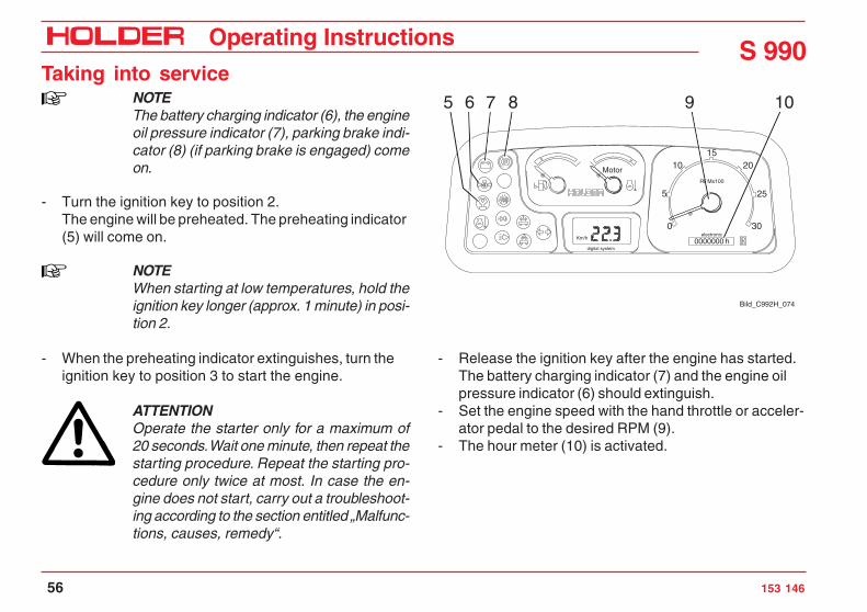
Taking into serviceNOTEThe battery charging indicator (6), the engineoil pressure indicator (7), parking brake indi-cator (8) (if parking brake is engaged) comeon.
- Turn the ignition key to position 2.The engine will be preheated. The preheating indicator(5) will come on.
NOTEWhen starting at low temperatures, hold theignition key longer (approx. 1 minute) in posi-tion 2.
- When the preheating indicator extinguishes, turn theignition key to position 3 to start the engine.
ATTENTIONOperate the starter only for a maximum of20 seconds. Wait one minute, then repeat thestarting procedure. Repeat the starting pro-cedure only twice at most. In case the en-gine does not start, carry out a troubleshoot-ing according to the section entitled „Malfunc-tions, causes, remedy“.
- Release the ignition key after the engine has started.The battery charging indicator (7) and the engine oilpressure indicator (6) should extinguish.
- Set the engine speed with the hand throttle or acceler-ator pedal to the desired RPM (9).
- The hour meter (10) is activated.
Km/h 0000000 h
25
1520
5
10
30
RPMx100
electronic0
Motor
digital system
1
2
5 96 7 8 10
Bild_C992H_074

Operating Instructions
153 146 57
S 990Taking into service
Checking the brakes and steering for proper function
- Make a short trial run and check the steering andbrakes for proper operation.
DANGERDo not drive a vehicle with a defective steer-ing and/or braking system.
Starting the engine with automatic preheating
Starting procedure
- Turn the ignition key to position 1.- The engine will be preheated. At temperatures below
+10°C the yellow lamp (2) and the preheating indicatorlight (1) will come on.
- When the yellow lamp (2) goes out, turn the ignitionkey to position 3 to start the engine.
- The automatic preheating will turn off some time afterstarting and the preheating indicator light (1) will goout.
NOTEIf the engine is not started, the preheatingprocedure will cease approx. 10 s after theyellow lamp (2) has gone out.
1
2 Bild_C288


Operating Instructions
153 146 59
S 990
Operation
Before starting to drive
When driving on public roads, observe the traffic regula-tions.
• When following a curve with a trailer or other attach-ments, do not forget to take the added length and draginto consideration.
DANGERAny parts of the attachments posing a traffichazard must be covered or identified withwarning signs before driving off.
• Switch off the differential lock when travelling in acurve.
• When driving on slopes, always drive downhill ifpossible; if you have to turn, only make a turn uphill.
• On steep slopes you can improve traction by activat-ing the differential lock.
• Drive across slopes only in accordance with theinstructions at the end of this section.
Driving safety rules
• Drive the tractor only from the driver’s station with thecab doors closed.
• Always adjust your speed to the driving conditionsand the load carried.
• Before driving, check that no-one is standing in theimmediate vicinity of the tractor.
• The driving behaviour of the tractor is strongly affect-ed by the weight and swing range of the attachments,trailers and, if fitted, ballasting. Therefore drive slowlywith heavy equipment and take the longer brakingdistance into consideration.

S 990Operating Instructions
60 153 146
OperationDrivingDriving with hydrostatic drive- Start the engine.- Preselect the direction of travel with the direction
switch (1).- Pull up the direction switch (1) and move it forward or
backwards (forward or reverse).
NOTEAfter the start of the engine, the directionswitch must be operated once if it was in theforward or reverse position when starting. Thisfeature is to prevent accidental movement ofthe vehicle when starting the engine.
NOTEYou can also reverse the direction of travelwhile driving at reduced speed.
CAUTIONThe tractor will brake strongly and speed upagain in the opposite direction.
- Set the speed range knob (2) (at the steering column)to the desired ground speed range:
ATTENTIONThe tractor must be stationary for switching.
1
Bild_C165
Bild_C992H_075
2

Operating Instructions
153 146 61
S 990Operation
Table of ground speed ranges
- Select the desired driving program with the drivingprogram switch (2). The set position is illuminated:
You can choose between 4 programs:
2
Bild_S 990_004
Position Marking Function Ground speed* Use
Lower position S Fast range 0 – 30 / 36 km/h Lower tractive force, eg for road travel
Centre position 0 Drive off Towing
Lower position L Slow range 0 – 11.5 km/h High tractive force, eg for working orpulling trailers on gradients
Range 1 and 2 eg road travel
Range 3 and 4 eg workapplications

S 990Operating Instructions
62 153 146
OperationTable of driving programs•
* Option
Position Marking Function Use
Range 0 STOP Traction drive off
Range 1 Hare symbol Maximum ground speed eg on roads
Range 2•• Turtle symbol Maximum ground speed eg on roads
Range 3 PTO symbolThe ground speed, which can be set with the fineadjustment knob, is adjusted automatically incase of a high power demand of the attachment,
eg when mowing.
Range 4 Snow blower symbolThe ground speed, which can be set with the fineadjustment knob, is adjusted automatically incase of high power demand of the attachment,
eg especially adjustedto the snow blower
• The driving programs can be optimized by your service centre for special applications, eg controlled constant speed.•• SDS* Driving Comfort functions only in driving range "L".
With SDS* Driving Comfort the driving speed is controlled with the accelerator pedal.

Operating Instructions
153 146 63
S 990Operation
Selecting road travel (transport speed)
The tractor is stationary.- Set the program switch (2) to speed range 1 or 2.
NOTEYou can also change the speed range whiledriving at reduced speed.
- Release the parking brake.- Depress the accelerator for the desired ground speed.
The tractor will start off and can be driven up to themaximum ground speed of the selected speed range.
- You can read the engine RPM (5) and ground speed(4) on the multifunctional display.
Setting the operating speed of programs 3 and 4
NOTEWith programs 3 and 4 you can set the groundspeed independently of the PTO RPM.
321
Bild_C992H_024
Km/h 0000000 h
25
1520
5
10
30
RPMx100
electronic0
Motor
digital system
1
2
4 5
Bild_C992H_076

S 990Operating Instructions
64 153 146
OperationThe tractor is stationary.- Set the fine adjustment knob (1) to 0.- Set the program switch (2) to speed range 3 or 4.- Adjust the PTO RPM with the hand throttle (3).
NOTEThe engine speed must be at least 1500 RPM asthe control only begins to function at this RPM.
NOTEYou can also change the ground speed rangeswhile driving.
The speed ranges 3 and 4 will set a speed controlled by thepower requirement of the PTO. This means, for example,that when the snow blower needs more power when meet-ing with higher resistance, the tractor will drive more slowly.When resistance decreases, the tractor will speed up to thepreset speed. Range 4 is especially trimmed to particularapplications.
- Release the parking brake.- The ground speed is controlled with the fine adjust-
ment knob (1).
321
Bild_C992H_024

Operating Instructions
153 146 65
S 990Operation
Adjusting the fine adjustment knob
NOTEYou can adjust the fine adjustment knob (1) anytime while driving for a fine and stepless control ofthe ground speed.
- In position 0 the tractor is stationary. When the knobis turned clockwise, the tractor will start off and in endposition 11 of the scale the maximum speed of therange will be reached.
- You can read the engine RPM and ground speed onthe multifunctional display.
NOTEIn this operating mode the tractor will drive auto-matically and will only need to be steered.
This mode is ideal for the operation of an attachment asyou can concentrate fully on controlling the attachment.
321
Bild_C992H_024

S 990Operating Instructions
66 153 146
OperationDriving with SDS (Special Drive System)*
For the selection of the programs 1, 3 and 4 at the programswitch (2) refer to the section on driving on pages 63 and64.
Driving program 2 (SDS)- Set the speed range knob (5) to range L.
ATTENTIONThe tractor must be stationary for switching.
- Set the program switch (2) to range 2.
NOTEIn this range, the fine adjustment knob (1) isnot operational. The control is assumed bythe pedal (4).
- Set the engine RPM with the hand throttle (3).- You can now control the ground speed steplessly with
the pedal (4) (accelerator).
* Option
321
Bild_C992H_024
4
Bild_S 990_002
5

Operating Instructions
153 146 67
S 990Operation
Operating the inching pedal
7 Inching pedal8 Accelerator
This function is effective in all driving programs.
NOTEIf you must reduce speed temporarily, youcan do it with the inching pedal.
ATTENTIONIf the inching pedal is floored, for example,for an EMERGENCY STOP, the tractor willbrake strongly.
- Operate the inching pedal (7). The tractor will deceler-ate and come to a complete stop.
- After passing the obstacle, release the inching pedal.The tractor will drive again at the preset speed.
Changing the direction of travel
- Preselect the new direction of travel with the directionswitch (9).
- The tractor will come to a standstill and accelerate inthe new direction of travel.
9
Bild_C170
87
Bild_C992H_026

S 990Operating Instructions
68 153 146
Operation
Bild_S 990_003
1
Driving with hydrostatic DUAL drive
- Set the speed range selector (1) to „S“.The DUAL Drive will only work in this range.
Table of ground speed ranges with DUAL Drive
* Depending on model
Position Marking Function Hydrostatic groundspeed*
Ground speed*with Dual Drive
Use
Lower position S Fast range 0 - 30 / 36 km/h 0 - 30 / 42 km/h Low tractive force,eg for road travel
Centre position 0 Drive off For towing
Upper position L Slow range 0 - 11.5 km/h / 14.5km/h
– High tractive force, egfor working or pullingtrailers on gradients

Operating Instructions
153 146 69
S 990Operation
- Set the program switch (2) to range 2.
ATTENTIONDrive the tractor warm for approx. 10-12 min.at range 2.
- Set the program switch to range 1.
NOTEThe functions of the travel drive are identicalexcept it does not lock the differential:When the ground speed* exceeds 25 km/h,the transmission automatically switches fromthe hydrostatic drive to the mechanical gear.When the speed drops again, the trans-mission goes back to the hydrostatic drive.
2
Bild_S 990_004
* Depending on model

S 990Operating Instructions
70 153 146
OperationSwitching the differential lock on
NOTEWith the differential lock you can improve trac-tion on soft, slippery ground. The lock is en-gaged when the engine speed is over 1000RPM. You can engage the differential lock onlybriefly by pressing the button momentarily.
ATTENTIONThe differential lock may only be used whendriving straight ahead.
- Depress the differential lock switch (1) at the rear andhold it.The indicator (2) in the multifunctional display will lightup red. An intermittent acoustic warning signal willsound at the same time.The differential lock acts on both axles.
Switching the differential lock off
- Release the differential lock switch (1).The indicator light (2) will extinguish and the acousticwarning signal in the multifunctional display cease.
1
Bild_C992H_027
Km/h 0000000 h
25
1520
5
10
30
RPMx100
electronic0
Motor
digital system
1
2
2
Bild_C992H_077

Operating Instructions
153 146 71
S 990Operation
Steering
The tractor has an hydraulically-actuated articulated steer-ing. The wheels also stay in track in curves so that attach-ments are guided without any lateral offset.
Steering
- Turn the steering wheel (1) in the desired direction.
The possible turning radii depend on the tires and track widthof your tractor. For exact information refer to the track widthtable in the section „Technical data“.
NOTEWith direct steering the steering angle is abouttwice as great as with indirect steering forthe same steering movement.(Ratio is approx. 1:2)
ATTENTIONWhen driving on roads, the two-stage steer-ing must be set to indirect steering (indicatorlight off) (risk of accidents).
* Option
Bild_C992H_028
12
Two-stage steering*
The tractor can be driven with two steering speeds.- Indirect steering (travelling on roads - slow steering speed.)- Direct steering (on the job - fast steering speed.)
- Depress the toggle switch (2) to the left. The indicatorlight in the toggle switch will come on and steering forworking is turned on.

S 990Operating Instructions
72 153 146
OperationBrakes
The service brake is a wet disc brake in the front axle. It ishydraulically actuated and acts on all four wheels. The parkingbrake is operated by an electric cylinder controlled with theparking brake switch.
Operating the service brake
- Depress the brake pedal (1).
Applying the parking brake
ATTENTIONThe parking brake is not intended to be usedfor braking while driving.
- Release the lock on the parking brake switch (2) anddepress the switch to the left.The parking brake will be engaged, the indicator lightin the switch and the parking brake indicator (3) in themultifunctional display will come on.
ATTENTIONOperate the parking brake only with the igni-tion turned on. On tractors with chassis num-bers up to 53400105H the ignition must stayon for 10 sec.
2
1
Bild_C992H_029
Km/h 0000000 h
25
1520
5
10
30
RPMx100
electronic0
Motor
digital system
1
2
3
Bild_C992H_078

Operating Instructions
153 146 73
S 990Operation
Releasing the parking brake
- Turn off the parking brake switch (2).The parking brake will be released, the indicator lightin the switch and parking brake indicator (3) willextinguish.
ATTENTIONWhen driving with the parking brake actuated,an acoustic warning signal will sound.
2
1
Bild_C992H_029
Km/h 0000000 h
25
1520
5
10
30
RPMx100
electronic0
Motor
digital system
1
2
3
Bild_C992H_078

S 990Operating Instructions
74 153 146
OperationDriving on slopes
DANGERDriving on slopes is dangerous as the tractorcan tip over if the centre of gravity exceedsthe tip-over limit on an extreme slope.
The following factors will reduce the hazard:- small or no load- low ground speed- low gradient- low tire inflation pressure
NOTEThe driving comfort and the traction of thetractor can be improved by reducing the in-flation pressure.
- large track widths- level, non-bumpy terrain.
For turning on slopes we recommend proceeding as shownin the drawing on the right.

Operating Instructions
153 146 75
S 990
Special operating instructions
Stationary operation
The tractor can be used for stationary operation, for exam-ple, to drive a water pump via the PTO shaft.
ATTENTIONPark the tractor on level ground in both direc-tions.
- Attach the stationary equipment to the PTO shaft (1) atthe front or rear.
- Set the program switch to 0.- Apply the parking brake.
DANGERBefore switching on the PTO, make sure no-one is standing in the vicinity of the tractorand the rotating PTO shaft.
Hydraulic oil for stationary operation
During stationary operation hydraulic oil can be tapped, forexample, for the operation of a hydraulic dump body.
Max. oil quantity ...................................................... 22 L
ATTENTIONBefore starting to drive after stationary opera-tion, first check that the hydrostatic steeringis operational. Turn the steering wheel fully tothe right and left several times to release airfrom the steering system.
Bild_C992H_030
1

S 990Operating Instructions
76 153 146
Special operating instructionsAdjusting the track width
You can widen the track width of the tractor by addingspacers.You have a choice of 3 different spacers.
DANGERObserve the safety notes on safe parking andjacking up for the wheel change in the main-tenance instructions.
- Remove the wheels. Turn the wheels inside out orinstall the selected spacers.
ATTENTIONIdentical spacers must be installed on all fourwheels.
NOTEThe arrows on the tires must show in the forwarddirection of rotation.
- Tighten the wheel nuts to the specified torque.
Torque to ............................................................ 340 Nm

Operating Instructions
153 146 77
S 990Special operating instructions
Operating the emergency gear release (hydrostaticDUAL drive only)
NOTEIf the engine was stalled and can not be restarted,the emergency gear release must be operatedbefore a new start.
- Fully depress the inching pedal.- Operate the starter briefly.- Pull the emergency gear release grip (1) to the rear.- Restart the engine.
Bild_S 990_023
1

S 990Operating Instructions
78 153 146
Special operating instructionsOperation in winterOil preheating*
Before starting the engine at temperatures below - 20 °C,turn on the heating element* to preheat the oil.
- Connect the preheating system plug to a 230 VACoutlet.
Observe the operating instructions of the manufacturer.
Winter diesel fuel
Whenever temperatures fall below 0°C, use winter diesel orsuper diesel fuel or additives recommended in the mainte-nance instructions.
Engine oil for winter operation
Fill engine oil with a suitable SAE class as recommended inthe maintenance instructions.The cold start capability of the engine can be reduced if thetemperature limits are underrun occasionally, but this will notdamage the engine.
Hydraulic system
The hydraulic functions are sluggish and slower during coldtemperatures. Bring the hydraulic system to operating tem-perature with some movements without a load.
Putting on snow chains
Snow chains can be mounted on the tires to improve grip.In the following table you will find the order numbers forRUD chains which fit on the listed tires. You can also fitsnow chains from other manufacturers if these have theproper dimensions.
Ballasting
The weight of the machine can be increased with ballastweights. The ballast weights must be applied parallel withthe same weight on each axle and side.
* Option
Type of tire Snow chain type (RUDOrder No.)
10.5-18 MPT 24 553 and 24 553
400/60-15.5 22 177
33x12.50 R 15/33x12.5-15 22 167
33x15.50-15 22 174
31x15.50-15 Terra 22 548
36x13.5-15 24 178

Operating Instructions
153 146 79
S 990
Operating the attachmentsWe have tested and approved a large number of possibleattachments for use with this tractor. Only attachments withthe CE mark may be used. We recommend contacting ourcustomer service before the installation of special equip-ment.
Possible attachments
For example:implements for orchardingimplements for soil cultivationmowerssnow removal equipmentand other municipal equipment.
Safety instructions for handling attach-ments
The tractor must be parked safely before the installation ofattachments.It must be secured against rolling, for example, with the park-ing brake or, if required, with chocks.
DANGERBe careful to avoid injuries due to crushingand cutting when coupling attachments.
DANGERNever let anyone stand between the tractorand an attachment or implement if the tractoris not secured against rolling.For driving on roads, the attachments mustbe lifted and secured against lowering.Observe the applicable safety regulations foryour attachment. Observe the operating in-structions and the safety rules for your at-tachment.
DANGERDuring work breaks, the attachment must al-ways be lowered to the ground in order torelieve the hydraulic cylinders. Accidents canoccur if lowering occurs in an uncontrolledway, for example, due to damage or acciden-tal movement of the control levers.
DANGERAny parts of the attachments posing a traffichazard must be covered or identified withwarning signs before driving.

S 990Operating Instructions
80 153 146
Operating the attachmentsAdditional information for attachments
When installing attachments on the front andrear lift arms, do not exceed the permissible to-tal weight, the maximum allowable axle loadsand tire carrying capacities of the tractor. Thefront axle of the tractor must always be loadedwith at least 20 % of the tractor’s curb weight.Before purchasing any equipment, make surethese conditions are met by performing the fol-lowing calculations or by weighing the tractor-equipment combinations.
Determination of the total weight, axle loads and tireload capacity including minimum ballasting
For the calculation you need the following data:
TL
(kg) Curb weight of the tractor1)
TV
(kg) Front axle load of the empty tractor1)
TH
(kg) Rear axle load of the empty tractor1)
GH
(kg) Total weight ofrear attachment/rear ballast 2)
GV
(kg) Total weight offront attachment/front ballast 2)
GvGH
TvTH
a b c d
a (m) Clearance between centre of gravityof front attachment/front ballast andcentre of front axle 2) 3)
b. (m) Wheelbase of the tractor1) 3)
c (m) Distance between centre of rear axleand centre of lower link ball 1) 3)
d (m) Distance between centrelower link ball and centre of gravity ofrear attachment/rear ballast 2)
1) See the technical data in the operating instructions2) See the price list and/or operating instructions of the
attachment3) Measure
Operating Instructions
153 146 81
S 990Operating the attachments
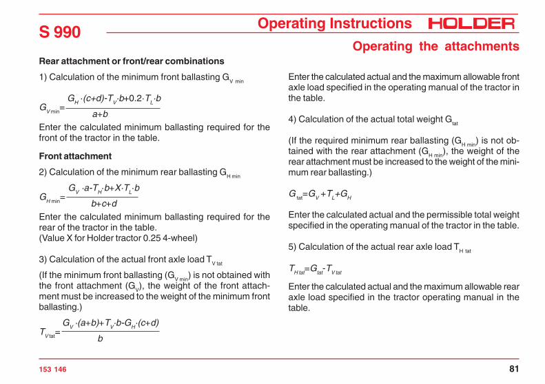
Rear attachment or front/rear combinations
1) Calculation of the minimum front ballasting GV min
GV min=
GH ·(c+d)-TV·b+0.2·TL·b
a+bEnter the calculated minimum ballasting required for thefront of the tractor in the table.
Front attachment
2) Calculation of the minimum rear ballasting GH min
GH min=
GV ·a-TH·b+X·TL·b
b+c+dEnter the calculated minimum ballasting required for therear of the tractor in the table.(Value X for Holder tractor 0.25 4-wheel)
3) Calculation of the actual front axle load TV tat
(If the minimum front ballasting (GV min
) is not obtained withthe front attachment (G
V), the weight of the front attach-
ment must be increased to the weight of the minimum frontballasting.)
TV tat= GV ·(a+b)+TV·b-GH·(c+d)
b
Enter the calculated actual and the maximum allowable frontaxle load specified in the operating manual of the tractor inthe table.
4) Calculation of the actual total weight Gtat
(If the required minimum rear ballasting (GH min) is not ob-tained with the rear attachment (G
H min), the weight of the
rear attachment must be increased to the weight of the mini-mum rear ballasting.)
G tat=GV +TL+GH
Enter the calculated actual and the permissible total weightspecified in the operating manual of the tractor in the table.
5) Calculation of the actual rear axle load TH tat
TH tat=Gtat-TV tat
Enter the calculated actual and the maximum allowable rearaxle load specified in the tractor operating manual in thetable.

S 990Operating Instructions
82 153 146
Operating the attachments6) Tire load capacityEnter the double value (two tires) of the permissible tireload capacity (eg see tire manufacturer’s documentation) inthe table.
Calculated valueMaximum permissiblevalue (acc. to operatingmanual)
Double permissable tyrecapacity(two tyres)
Minimum ballastfront/rear
/ kg - -
Total weight kg ≤ kg -
Front axle kg ≤ kg ≤ kg
Rear axle kg ≤ kg ≤ kg
The minimum ballast must be applied as implemented device or ballast-weight at the tractor!The calculated values must be less than or equal to (≤) the max. permissable values!
Operating Instructions
153 146 83
S 990Operating the attachments
Installation of attachments
The various attachments are attached to the front lift or rearlift*.There are 2 different coupling categories:Category I Pin diameter 22 mmCategory (II) Pin diameter 28 mmThe tractor is adjustable to both categories. For this adjust-ment the catch hook bars must be adjusted and the catchhooks equipped with reducer sleeves or not.
DANGEROnly use the following specified devices forthe installation of your attachment.Secure the attachment against shifting orrolling.
* Option

S 990Operating Instructions
84 153 146
Operating the attachmentsAdjusting the catch hooks
The catch hooks can be adjusted laterally and in length.- Measure the distance between the pins on your
attachment.- Release the clamping screws (8) on both sides.- Slide the catch hook (7) laterally until the required
distance is reached.- Retighten the clamping screws.- Attachments of Category II can be picked up directly
with the catch hooks (7).- For attachments of Category I install the reducer
sleeves (6) on the left and right hook.
Adjusting the hitch insert length
- Loosen the lock nuts and clamping screws (1) at thelower link (2).
- Loosen the screw at the pin (3) and pull the pin out.- You can adjust the hitch inserts (4) to one of 3 positions.- Insert the pin (3) into the hole and secure with the
screw.- Retighten the locknut and clamping screws (1).
DANGERNever let anyone stand between the tractorand an attachment or implement.
1 2 3 4 5
6
78 Bild_S 990_018
- Drive the tractor to the attachment to be picked up.
- Steer the catch hooks (7) below the pick-up pins of theattachment.
- Raise the front lift, until the quick detach coupling (5)closes and engages.
Hole Position Used for
1st hole Front Category I and II
2nd hole Centre Category I
3rd hole Rear Special attachments
Operating Instructions
153 146 85
S 990Operating the attachments
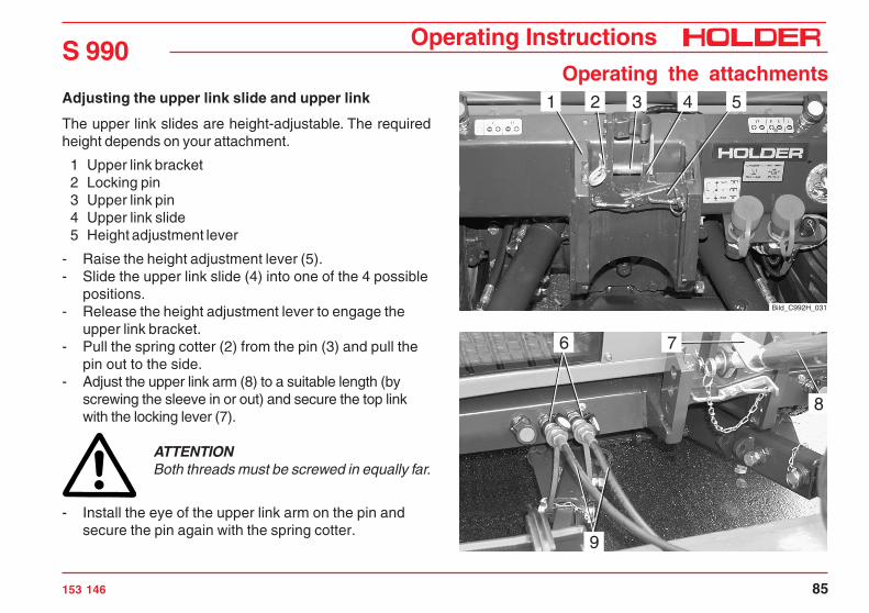
Adjusting the upper link slide and upper link
The upper link slides are height-adjustable. The requiredheight depends on your attachment.
1 Upper link bracket2 Locking pin3 Upper link pin4 Upper link slide5 Height adjustment lever
- Raise the height adjustment lever (5).- Slide the upper link slide (4) into one of the 4 possible
positions.- Release the height adjustment lever to engage the
upper link bracket.- Pull the spring cotter (2) from the pin (3) and pull the
pin out to the side.- Adjust the upper link arm (8) to a suitable length (by
screwing the sleeve in or out) and secure the top linkwith the locking lever (7).
ATTENTIONBoth threads must be screwed in equally far.
- Install the eye of the upper link arm on the pin andsecure the pin again with the spring cotter.
6
9
7
8
Bild_C992H_031
1 2 3 4 5

S 990Operating Instructions
86 153 146
Operating the attachmentsCoupling the hydraulic hoses
ATTENTIONThe hydraulic couplings on the truck mustbe depressurized before their connection. Thecouplings on the tractor and the hydraulichoses must be clean.
NOTEEach attachment has different functions andhydraulic hoses to the control unit. Observethe operating instructions supplied with yourattachment and make yourself familiar withthe functions and colour codes.
- Open the protective caps on the hydraulic couplings (1).- Attach the colour-coded hydraulic hoses (2) of the
attachment to the hydraulic couplings of the samecolour on the tractor.
ATTENTIONThe hydraulic male couplings fit on each cou-pling and can therefore be connected incorrectly.With the connection you decide which func-tion/movement of the attachment is actuallyto be performed with the control lever as-signed to the coupling.
DANGERIf you are not sure about the functions, de-termine them by testing in a safe place.
Bild_C266
1 2

Operating Instructions
153 146 87
S 990Operating the attachments
Installing the articulated shaftsOnly use shafts suitable and intended for the attachment.These shafts are supplied with the attachment. The lengthof the articulated shaft must be adjusted before the firstinstallation. In case of doubt please contact our customerservice. Observe the installation instructions for the articu-lated shaft when installing it.
DANGERShut off the engine before the installation. Fitthe protective devices as specified after theinstallation!
Removing attachments- Drive the attachment to its storage place and lower it
with the front lift.- Stop the engine, but do not turn off the ignition.- Operate all control levers for the front lift several
times in all directions. This will relieve the pressure inthe hydraulic system .
- Slide the outer ring of the hydraulic couplings (1) backand disconnect the hydraulic hoses (2).
- Close the protective caps on the hydraulic couplings(as for item 4).
- Remove the upper link from the pin of the upper linkbracket.
- Pull the quick detach couplings (3) up to release theattachment pins.
- Lower the front lift and back away carefully. Bild_C267
4 2
3
1
Bild_C992H_032

S 990Operating Instructions
88 153 146
Operating the attachmentsOperating the joystick
1 Pushbutton 1 for joystick level 12 Pushbutton 2 for joystick level 23 Pushbutton 3 for joystick level 34 Joystick (joystick level 0 without pushbutton opera-
tion)5 Master switch for working hydraulics
NOTEThe joystick controls those functions of theattachments which are connected directly orto the front or rear hydraulic couplings. Thecouplings and labels for the joystick are col-our coded, ie the colours match to the func-tion.
DANGERDue to the variety of attachments and con-nections, however, we recommend a trial runof the movement at a safe place without dan-ger to persons or risk of material damagebefore starting operation.
432
5
1
Bild_C176
The joystick function can only be performed when the mas-ter switch (5) is switched on.
NOTEThe joystick can be moved forward and backas well as to the right and left: The functionsare shown on the label.

Operating Instructions
153 146 89
S 990Operating the attachments
Joystick operation
(proportional for sensitive operation)
Direction of joystickForward/back Left /right
Joystick level 0(without button)
Front lift Y0Fwd.: loweringBack: liftingFloat position on membrane keyboard
Front right quick coupler X0
Float position X0 on membrane keyboard 2Joystick level 1(with button 1 pressed)
Dumping device / rear Lift * Y1Fwd.: loweringBack: liftingFloat position Y1 on membrane keyboard 1
Front right quick coupler X1
Float position Y1 on membrane keyboard 3Joystick level 2(with button 2 pressed)
Front left quick coupler Y2
No float position intended
Rear left quick coupler X2
No float position intendedJoystick level 3(with button 3 pressed)
Front lift tilt control Y3(included in front lift)Fwd.: tilt rightBack: tilt left
Lateral control of the front lift X3Alternatively: Quick couplerLeft: pivot leftRight: pivot right
* Selectable with 3-way cock

S 990Operating Instructions
90 153 146
Operating the attachmentsOperating the front lift
The following movements are possible:
Turn on the master switch (5) for working hydraulics.- Push the joystick (4) forward.
• The front lift (attachment) will be lowered.
You can stop the movement by releasing the joystick.- Pull the joystick (4) back.
• The front lift (attachment) will be raised.
The float position is turned on with the membrane key-board.
- To turn on, press key (6). The red LED indicator willcome on.• The float position the front lift will be
turned on, ie the attachment can be moved by theapplication of an external force.
- To turn off, press key (6). The red LED indicator willextinguish.
Front lift tilt control
- Keep key (3) depressed and push the joystick (4)forward.• The front lift will tilt to the right.
432
5
6
1
Bild_C177
- Keep key (3) depressed and pull the joystick (4) back.• The front lift will tilt to the left.
Lateral control of the front lift
- Keep key (3) depressed and push the joystick (4) tothe right.• The front lift will pivot to the right.
- Keep key (3) depressed and push the joystick (4) tothe left.• The front lift will pivot to the left.

Operating Instructions
153 146 91
S 990Operating the attachments
Operating the front lift with the membrane keyboard
The following movements are possible:
Turn on the master switch (3) for working hydraulics.
- Keep key (4) depressed for approx. 1 second. The redLED indicator (5 and 2) will come on for approx. 5seconds.• The front lift (attachment) will be lifted
until the LED indicator extinguishes.
You can stop the movement by pressing key (4,7) or bymoving the joystick.- For lowering, press key (7) for approx. 1 second. The
red LED indicator (6 and 2) will come on.• The front lift (attachment) will be lowered
until the LED indicator extinguishes.
The lifting and lowering speed can be controlled by turningthe adjustment knob (1).- Turn the rotary knob (1) to the left - slower.- Turn the rotary knob (1) to the right - faster.
You can also turn on the float position:- To do so, press key (9) for approx. 1 second. The red
LED indicator (8) will come on.• The float position of the front lift is
turned on, ie the attachment can be moved by theapplication of an external force.
- To turn it off, press key (9,7 or 4) or move the joy-stick. The red LED indicator (8) will extinguish.
4
2 31
9
678 5 Bild_C178

S 990Operating Instructions
92 153 146
Operating the attachmentsSwitching the front lift to double-acting
The front lift can be switched from single-acting to double-acting.
- To select double-acting, press key (5). The red LEDindicator (6) will extinguish.
- To select single-acting, press key (5). The red LEDindicator (6) will come on.
NOTE:When the truck is started again or when turn-ing on the master switch for working hydrau-lics, the front lift is always activated in thesingle-acting mode.
Adjusting the tilt with membrane keyboard
- Keep key (4) depressed.• The front lift will tilt to the right.
You can stop the movement by releasing the key.- Keep key (3) depressed.
• The front lift will tilt to the left.- Press key (1). The red LED indicator (2) will come on.
• The float position of the tilt control is turned on, iethe attachment can be moved by the application ofan external force.
- To turn it off, press key (1, 3 or 4) or move the joy-stick. The red LED indicator (2) will extinguish.
5
32 41
6 Bild_C179

Operating Instructions
153 146 93
S 990Operating the attachments
Lateral control with the membrane keyboard
- Keep key (4) depressed.• The front lift will shift to the right.
You can stop the movement by releasing the key.- Keep key (3) depressed.
• The front lift will pivot to the left.- Press key (1) for approx. 1 second. The red LED
indicator (2) will come on.• The lateral control float position is turned on, ie theattachment can be moved by the application of anexternal force.
- To turn it off, press key (1, 3 or 4) or move the joy-stick. The red LED indicator (2) will extinguish.
Transport safety
The joystick and membrane keyboard can be locked withthe master switch (5):
- Master switch off – joystick and membrane keyboarddisabled
- Master switch on – joystick and membrane keyboardenabled
NOTEIf the joystick function is locked, you canprevent any unintended movement of the at-tachment through accidental contact with thejoystick or the membrane keyboard.Transport lock for road travel.
32 4 51
Bild_C180

S 990Operating Instructions
94 153 146
Operating the attachmentsExternal operation of the front lift
You can operate the front lift from outside the cabin.
ATTENTIONWhen you leave the cabin, set the directionswitch to neutral and apply the parking braketo prevent the tractor from rolling.
- To raise the front lift, press the top pushbutton (1).
The front lift will be raised as long as the pushbutton ispressed.
- To lower the front lift, press the bottom pushbutton (1).
The front lift will be lowered as long as the pushbutton ispressed.
Bild_S 990_019
1

Operating Instructions
153 146 95
S 990Operating the attachments
Flow rate limiting for joystick
1 Key for individual flow rate limiting for each individualjoystick function
- Turn on the master switch for the working hydraulics.
With the flow rate limiting you can save the lifting or lower-ing speed individually.- Operated the joystick (4) until the desired speed at
the cylinder is reached, then press key (1).
This value will be stored as the maximum value and willapply for the entire joystick stroke.
If the full volume flow is required again, proceed as follows:- Move the joystick (4) as far as possible and press
key (1).
The full volume flow will be enabled again for the full joy-stick stroke.
Setting key for float position button
2 Key for setting the joystick button (3) to „float posi-tion of front lift“
- Press key (2).
The button (3) will now also be activated as float positionbutton for the front lift.Two flashing LED indicators show the operating state.
NOTEYou can also activate and de-activate the floatposition with the button (3).The LED indicator (5) shows the operating state.
- To reverse the selection, press key (2) again.
3
5
4
21
Bild_C212

S 990Operating Instructions
96 153 146
Operating the attachmentsOperating the rear lift
The following movements are possible:
Turn on the working hydraulics master switch.- Set the changeover lever (1) at the rear down to the
„rear lift“ position.- To raise the rear lift, press key (2) and pull the joy-
stick (3) back.• The rear lift (attachment) will be raised.
You can stop the movement by releasing the joystick.- Press key (2) and push the joystick (3) forward.
• The rear lift (attachment) will be lowered.
The float position is turned on with the membrane key-board.
- To turn on, press key (4). The red LED indicator willcome on.• The float position of the rear lift is
turned on, ie the attachment can be moved by theapplication of an external force.
- To turn off, press key (4). The red LED indicator willextinguish.
3
4
2
Bild_C213* Option
1 Bild_C992H_092

Operating Instructions
153 146 97
S 990Operating the attachments
External operation of the rear lift*
The rear lift can be operated from outside the cabin.
ATTENTIONWhen you leave the cabin, set the directionswitch to neutral and apply the parking braketo prevent the tractor from rolling.
- To raise the rear lift, press the top pushbutton (1).
The rear lift will be raised as long as the pushbutton ispressed.
- To lower the rear lift, press the bottom pushbutton (1).
The rear lift will be lowered as long as the pushbutton ispressed.
* Option
1
Bild_C271
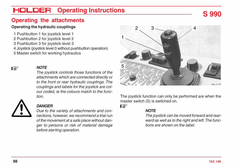
S 990Operating Instructions
98 153 146
Operating the attachmentsOperating the hydraulic couplings
1 Pushbutton 1 for joystick level 12 Pushbutton 2 for joystick level 23 Pushbutton 3 for joystick level 34 Joystick (joystick level 0 without pushbutton operation)5 Master switch for working hydraulics
NOTEThe joystick controls those functions of theattachments which are connected directly orto the front or rear hydraulic couplings. Thecouplings and labels for the joystick are col-our coded, ie the colours match to the func-tion.
DANGERDue to the variety of attachments and con-nections, however, we recommend a trial runof the movement at a safe place without dan-ger to persons or risk of material damagebefore starting operation.
The joystick function can only be performed are when themaster switch (5) is switched on.
NOTEThe joystick can be moved forward and rear-ward as well as to the right and left. The func-tions are shown on the label.
432
5
1
Bild_C176

Operating Instructions
153 146 99
S 990Operating the attachments
Operating the green hydraulic couplings*
- Move the joystick (4) to the left or right.• The green hydraulic couplings front rightwill be supplied with pressure.
You can stop the movement by releasing the joystick.The float position is turned on with the membrane keyboard.- To turn on, press key (7). The red LED indicator will
come on.• The float position of the green hydraulic couplings
is turned on, i.e. the attachment can be movedby the application of an external force.
- To turn off, press key (7). The red LED indicator willextinguish.
Operating the blue hydraulic couplings*
- Press key (1) and push the joystick (4) to the left orright.• The blue hydraulic couplings at the front rightwill be supplied with pressure.
You can stop the movement by releasing the joystick.The float position is turned on with the membrane keyboard.- To turn on, press key (6). The red LED indicator will
come on.- To turn off, press key (6). The red LED indicator will
extinguish.
Operating the yellow and white hydraulic couplings*- Press key (2) and push the joystick (4) to the left or
right.• The yellow hydraulic couplings at the rear left
will be supplied with pressure.- Press key (2) and move the joystick (4) forward or
back.• The white hydraulic couplings at the front left
will be supplied with pressure.NOTEThe yellow and white hydraulic couplings do nothave a float position.
4
67
21
Bild_C215
* Option

S 990Operating Instructions
100 153 146
Operating the attachmentsTurning on the front PTO
DANGERThe PTO switch (1) must be switched off.
- Start the engine.- Select the required PTO SPM with the PTO push-pull
rod (3).
NOTEThe push-pull rod (3) is located at the frontright at the front bracket.
DANGERBefore turning the PTO on, make sure thatno-one is standing close enough to the trac-tor and the driven attachment to be hurt.
The PTO gear has 3 positions.The possible positions are shown on the instruction plate (2).
- Set the push-pull rod to the centre position.The PTO gear will be switched off.
- Pull the push-pull rod out.The PTO speed will be 540 RPM at an engine speedof 2200 RPM.
Bild_C992H_093
1
Bild_S 990_007
2
3

Operating Instructions
153 146 101
S 990Operating the attachments
- Push the push-pull rod in.The PTO speed will be 1000 RPM at an engine speedof 2390 RPM.
ATTENTIONNever turn the PTO on with the engine off!
- Increase the engine speed to 1500-1800 RPM.- Release the lock at the safety switch (1) and depress
the switch. The front PTO is now turned on.- To turn the PTO off, press the safety switch (1) up.- If the PTO is no longer required, put the push-pull rod
(3) back to the neutral position.
DANGERAfter the PTO is turned off, the installed at-tachment could continue to run. Wait until theattachment is stationary before working on itagain.
Bild_C992H_093
1
Bild_S 990_007
2
3

S 990Operating Instructions
102 153 146
Operating the attachmentsTurning on the rear PTO
NOTEThe rear PTO can be turned on with the con-trol lever (3) in the area of the articulated joint.The control positions are shown on the in-struction plate (2).
- The safety switch (1) must be switched off.- Pull the control lever (3) up to turn on the rear PTO.
DANGERBefore turning the PTO on, make sure thatno-one is standing close enough to the trac-tor and the driven attachment to be hurt.
- Release the lock at the safety switch (1) and depressthe switch. The rear PTO is turned on.
- To turn the PTO off, press the safety switch (1) up.- Push the control lever (3) down again.
DANGERAfter the PTO is turned off, the installed at-tachment could continue to run. Wait until theattachment is stationary before working on itagain.
Bild_C992H_093
1
Bild_S 990_008
Ein
Aus
32

Operating Instructions
153 146 103
S 990Operating the attachments
Operating the hydraulic accumulator* (front lift)
The hydraulic accumulator allows the ground pressure of theattachment to be decreased steplessly and the front axle loadto be increased. This improves the climbing ability.
- Press key (5). The LED indicator (7) will come on.
The electronic pressure sensor (2) with a digital display al-ways shows the current pressure of the front lift with thefloat position turned off.
- Press the „MODE“ key (3).- S.P.1 will appear in the display. After 2 seconds the
current setting will flash.- If you want to change the setting, press key (1) to
reduce the value or key (4) to increase the value untilthe ground pressure of the machine is changed asdesired.
- The value S.P.1 must be less than the pressure witha lifted attachment.
NOTEAfter 3 seconds without key activation thedisplay will revert and the settings will bestored.
* Option
Adjusting control sensitivity (hysteresis)
- Press the „MODE“ key (3) twice within 3 seconds.- HYS.1 will appear in the display. After 2 seconds the
current setting will flash.- Press key (1) to reduce the value or key (4) to in-
crease the value if you want to change the setting.The value should be between 5 and 10 bar.
NOTEThe gas pressure in the diaphragm accu-mulator is 30 bar.
65
7
431 2
Bild_C188
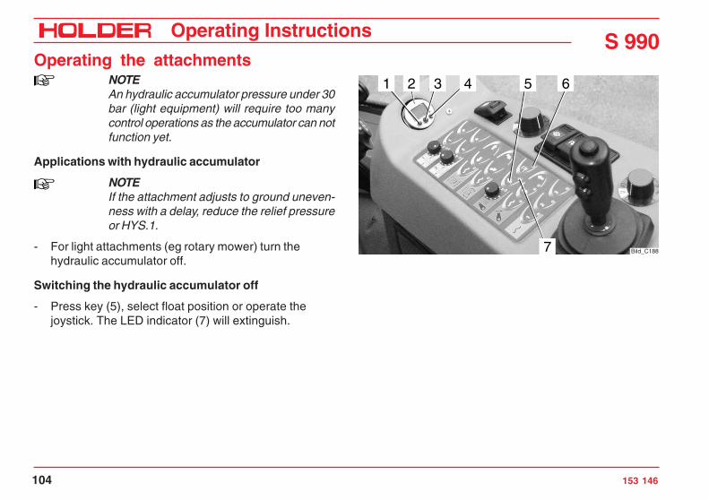
S 990Operating Instructions
104 153 146
Operating the attachmentsNOTEAn hydraulic accumulator pressure under 30bar (light equipment) will require too manycontrol operations as the accumulator can notfunction yet.
Applications with hydraulic accumulator
NOTEIf the attachment adjusts to ground uneven-ness with a delay, reduce the relief pressureor HYS.1.
- For light attachments (eg rotary mower) turn thehydraulic accumulator off.
Switching the hydraulic accumulator off
- Press key (5), select float position or operate thejoystick. The LED indicator (7) will extinguish.
65
7
431 2
Bild_C188

Operating Instructions
153 146 105
S 990Operating the attachments
Operating the attachment variable pump* (adjustableto 0-120 L)
The attachment variable pump is a device for operating at-tachments with a high hydraulic power requirement, eg acylinder mower. The pump is operated electrically from thedriver’s station.
- Connect the hydraulic hoses of the front or rearattachment to the return line (1) and supply line (2)quick couplings and, if necessary, to the blackleakage oil coupling (4).
- Plug the coded plug of the attachment into the socket(3) beside the quick couplings.
NOTEOnly one coded plug may be plugged in atthe front or rear.
NOTEIf a new or unknown attachment is to be in-stalled, the cable harness for attachmentencoding 204-80-72 must be used. The cor-rect encoding must be determined after con-sultation with the manufacturer of the attach-ment and Holder.
* Option
Bild_C992H_033
1 2 43

S 990Operating Instructions
106 153 146
Operating the attachmentsATTENTIONTurn on the safety switch (6) only at low en-gine speed.
- Turn the rotary knob (5) to 0.- Release the lock at the safety switch (6) and depress
the switch. The indicator in the switch will light.
ATTENTIONAfter the engine speed was increased, theoil flow may only be increased slowly.
- Turn the rotary knob (5) for setting the oil flow from 0to 120 litres/min maximum to the desired rating forthe attachment.
NOTEThe coded plug of the attachment will deter-mine the maximum oil flow rate for the re-lated attachment (for safety reasons).
The numerical value 11 on the ring corresponds to themaximum oil flow rate determined by the encoding.
Bild_C992H_034
5 6

Operating Instructions
153 146 107
S 990Operating the attachments
NOTEThe attachment variable pump will attemptto maintain the oil flow rate specified by theattachment plug and potentiometer, even ifthe engine RPM drops.Only when the maximum swash angle of thepump is reached will the oil flow be reducedwhen the RPM are reduced (refer to diagram).
ATTENTIONWhen the attachment is no longer in use, al-ways turn the pump off with the safety switchso that the hydraulic oil will not heat up un-necessarily.
Switching off the attachment variable pump
- Turn the safety switch (6) off. The indicator in theswitch will extinguish.
NOTEWhen you stop the engine without switchingoff the attachment variable pump, the pumpwill not start after the engine is started again(for safety reasons).
To start the attachment variable pump, you must set therotary knob (5) to 0 and the turn the safety switch (6) off andon once.
Bild_C992H_034
5 6
50 L/min
60 L/min
70 L/min
80 L/min
90 L/min
120 L/min
100 L/min
S990 Variable pump flow
RPM Diesel engine (1/min)
Flo
w (
L/m
in)
0
10
20
30
40
50
60
70
80
90
100
110
120
130
900 1000 1100 1200 1300 1400 1500 1600 1700 1800 1900 2000 2100 2200 2300 2400 2500 2600
Bild_S 990_031_GB

S 990Operating Instructions
108 153 146
Operating the attachmentsOperating the hydraulic system* (fixed setting 80 L)
The hydraulic system is a facility for operating attachmentswith a fixed hydraulic power requirement. The hydraulic sys-tem is operated electrically from the driver’s station.
- Connect the hydraulic hoses of the attachment to thescrew couplings (1) and (2) and the leakage oil cou-pling (3).
ATTENTIONTurn on the safety switch only at low enginespeed.
- Release the lock on the safety switch (4) and depressthe switch. The indicator in the switch will light.
ATTENTIONIncrease the speed of the engine slowly.
- The attachment will be supplied with an oil flow ofapprox. 80 L/min at the rated RPM.
Bild_S 990_021
1 2 3
Bild_S 990_022
4

Operating Instructions
153 146 109
S 990Operating the attachments
ATTENTIONThe attachment must be to set to 80 litres/min, otherwise damage to the attachment orhazards for people standing in the vicinity canresult.
ATTENTIONWhen you no longer use the attachment, al-ways turn the pump off with the safety switchso that the hydraulic oil will not heat up un-necessarily.
Never leave the hydraulic system turned on:- if the engine is running and no load is connected to
the couplings- or it is not in operation.
The resulting overheating can damage the hydraulic sys-tem.
Switching off the hydraulic system
- Turn the safety switch (4) off. The indicator in theswitch will extinguish.
Bild_S 990_022
4

S 990Operating Instructions
110 153 146
Operating the attachmentsOperating the hydraulic dumping device
The hydraulic dumping device allows the easy and fast raisingof the dumping subframe. The dumping device tips the dumpbody* to the rear.
- Start the engine.
Changeover lever for the device to be driven:- Set the changeover lever (1) at the rear forward to the
„dumping device“ position.
DANGERMake sure that no-one is standing in the dan-ger zone at the rear end.
- Press the key (2) and pull the joystick (3) back.• The dumping device will be raised. To stop themovement, release the joystick.
- To lower the dumping device, press the key (2) andmove the joystick (3) forward.
DANGERMake sure that no-one is standing in the dan-ger zone at the rear end. Danger or beingcrushed!
The dumping device will be lowered.
* Option
3
2
Bild_C187
1 Bild_C992H_092
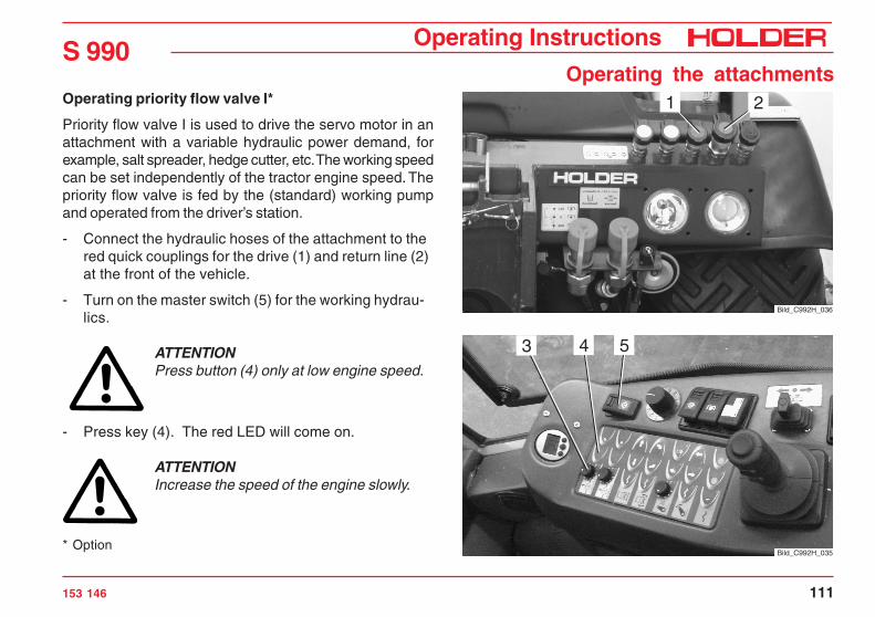
Operating Instructions
153 146 111
S 990Operating the attachments
Operating priority flow valve I*
Priority flow valve I is used to drive the servo motor in anattachment with a variable hydraulic power demand, forexample, salt spreader, hedge cutter, etc. The working speedcan be set independently of the tractor engine speed. Thepriority flow valve is fed by the (standard) working pumpand operated from the driver’s station.
- Connect the hydraulic hoses of the attachment to thered quick couplings for the drive (1) and return line (2)at the front of the vehicle.
- Turn on the master switch (5) for the working hydrau-lics.
ATTENTIONPress button (4) only at low engine speed.
- Press key (4). The red LED will come on.
ATTENTIONIncrease the speed of the engine slowly.
* OptionBild_C992H_035
543
Bild_C992H_036
21

S 990Operating Instructions
112 153 146
Operating the attachments- Select the desired engine speed with the hand throt-
tle.- Set the rotary knob (3) to the operating speed required
for the attachment.Turning clockwise increases the speed, turninganticlockwise lowers it.
ATTENTIONIf the flow rate selected is higher than intendedfor the attachment, the attachment can bedamaged or people standing in the vicinitycan be injured.
- The servo motor in the attachment is supplied with anoil flow of 0 to 25 litres/min.
ATTENTIONIf the attachment is not in use, always turnthe priority flow valve off with key (4) to pre-vent any unnecessary overheating of thehydraulic oil.
Bild_C992H_035
543
Do not leave the priority flow valve on:- If the engine is running and no load is connected to
the couplings- or it is not in operation.
The resulting overheating can damage the hydraulic sys-tem.
Turning off the priority flow valve
- Press key (4). The red LED will extinguish.

Operating Instructions
153 146 113
S 990Operating the attachments
Operating priority flow valve II*
Priority flow valve II is used to drive the servo motor in anattachment with a variable hydraulic power demand, forexample, salt spreaders, hedge cutters, etc. The workingspeed can be set independently of the tractor engine speed.The priority flow valve is fed by the tandem working pumpand operated from the driver’s station.
- Connect the hydraulic hoses of the attachment to thered quick couplings for the drive (1) and return line (2)at the rear of the tractor.
- Turn on the master switch (5) for working hydraulics.
ATTENTIONPress button (4) only at low engine speed.
- Press key (4). The red LED will come on.
ATTENTIONIncrease the speed of the engine slowly.
* OptionBild_C992H_037
543
Bild_S 990_009 2
1

S 990Operating Instructions
114 153 146
Operating the attachments- Select the desired engine speed with the hand throt-
tle.- Set the rotary knob (3) to the operating speed required
for the attachment.Turning clockwise increases the speed, turninganticlockwise lowers it.
ATTENTIONIf the flow rate selected is higher than intendedfor the attachment, the attachment can bedamaged or people standing in the vicinitycan be injured.
- The servo motor in the attachment is supplied with anoil flow of 0 to 25 litres/min.
ATTENTIONIf the attachment is not in use, always turnthe priority flow valve off with the button (4)to prevent any unnecessary overheating ofthe hydraulic oil.
Bild_C992H_037
543
Do not leave the priority flow valve on:- If the engine is running and no load is connected to
the couplings- or it is not in operation.
The resulting overheating can damage the hydraulic sys-tem.
Turning off the priority flow valve
- Press key (4). The red LED will extinguish.

Operating Instructions
153 146 115
S 990Operating the attachments
Connecting line for priority flow valves 1 and 2
The oil flow of priority flow valves 1 and 2 can be combinedwith the connecting line. This will result in a flow rate of 0 to50 litres/min.
- Set the changeover lever (1) in the area of the articu-lated joint to the down position.
The priority flow valves 1 and 2 are now connected.
- Set the rotary knob for priority flow valve 2 to themax. position. You can set the desired flow rate withthe rotary knob for priority flow valve 1.
ATTENTIONIf the flow rate selected is higher than intendedfor the attachment, the attachment can bedamaged or people standing in the vicinitycan be injured.
- Set the changeover lever (1) to the left position.
The priority flow valves 1 and 2 are now separated.
1
Bild_S 990_049


Operating Instructions
153 146 117
S 990
Other operations
Operating the driver’s cabin
Operating the roof hatch
Opening the roof hatch
- Press in the knob (2) on the side of the handle.- Push the handle (1) up. The roof hatch will open to the
rear.
Removing the roof hatch
NOTEThe roof hatch can be used as an emergencyexit in case of danger.
- Open the roof hatch.- Press out the inner plastic clip (4) to the back.- Press the outer plastic clip (3) inward.- Swing the roof hatch up with the handle (1).
43 3
2
1
Bild_C194

S 990Operating Instructions
118 153 146
Other operationsOperating the windshield wiper/washer
NOTEThe tractor is provided with a front wiper. Awasher system is also installed. The washersystem draws its water from the washingwater reservoir located at the front left in thecabin.
Front windshield wiper/washer
- Turn the rotary switch (1) for the front windshieldwiper to stage J.The front windshield wiper will be switched to intermit-tent operation.
- Turn the rotary switch (1) to stage I.The windshield wiper will be set to slow continuousoperation.
- Turn the rotary switch (1) to stage II.The windshield wiper will be set to fast continuousoperation.
- Push the button (2).The front windshield washer will operate and sprayonly as long as the button is pressed.
2
1
Bild_C195

Operating Instructions
153 146 119
S 990Other operations
Lights
Turning on and operating the lights
NOTEThe preheat/starter switch is set to position 1
- Put the light switch (2) to position 1.The front position lights (3,6) and the tail lights (10,14)(parking light) will come on.
- The position light indicator (3) in the multifunctionaldisplay will come on.
- Put the light switch (2) to position 2.The front headlights (1, 8) (low beam) will come on.
Turning on high beam
- Put the light switch (2) to position 2.- Move the turn signal lever (1) down. The headlights
(2, 7) will be set to high beam.- The high beam indicator (4) in the multifunctional
display will come on.
NOTETo flash the headlights, pull the turn signallever up.
2
1
Bild_C196
Km/h 0000000 h
25
1520
5
10
30
RPMx100
electronic0
Motor
digital system
1
2
3
4Bild_C992H_099

S 990Operating Instructions
120 153 146
Other operations1 Low beam head-
light, right2 High beam head-
light, right3 Turn signal and
position light, right4 Top headlight5 Top headlight6 Turn signal and
position light, left7 High beam head-
light, left8 Low beam head-
light, left9 Brake light
10 Tail lightTurn signal light, left
11 Licence plate light12 Top strobe warning
light mount/workinglight*
13 Back-up light14 Tail light
Turn signal light,right
15 Brake light
* OptionBild_C992H_038
1
2
3 4 5 6
8
7
Bild_C992H_03912
15141310 119

Operating Instructions
153 146 121
S 990Other operations
Turning on the top headlights
NOTEIf front attachments are installed and the bot-tom headlights are hidden, you may turn onthe top headlights.
- Push the toggle switch for top headlights (2) to turn onthe top headlights (5, 6).
NOTEThe functions high beam and headlight flash-ing are only available in the lower headlights.
Activating the left / right turn signal
- Push the turn signal lever (1) forward to activate theleft turn signal lights (7, 9).
- The turn signal indicator in the multifunctional displaywill come on.
- Push the turn signal lever (1) back to activate theright turn signal lights (4, 8).
Operating the horn
- Push on the end of the direction lever (3) to sound thehorn.
3
2
1
Bild_C992H_040
Bild_C992H_041
4 5 6 7 Bild_C992H_042
89

S 990Operating Instructions
122 153 146
Other operationsOperating the 4-way hazard flashers
- Push the hazard flasher switch (1) to activate the 4-way flashers.
Turning on the top strobe warning light*
NOTEThe top strobe warning light may only beturned on if the tractor is used for applica-tions on public roads.
- Push the strobe warning light switch (2) to turn on thetop strobe warning light (3).
* Option
3
Bild_C200
1 2 Bild_C992H_043

Operating Instructions
153 146 123
S 990Other operations
Turning on the working lights*
NOTEThe working light must not be used in publictraffic.
- Push the working light switch (1) to turn on the work-ing light (2).
Dome light
Turning on the dome light
NOTEThere is an dome light mounted in the cabinroof on the left and right side.
- Flip the switch (1) to turn on.
* Option
Bild_C2011
2
1
Bild_C202
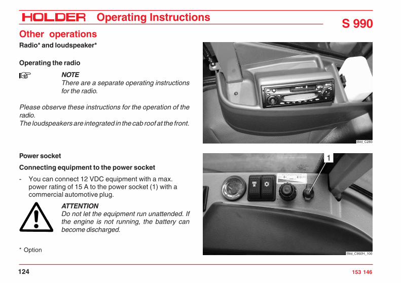
S 990Operating Instructions
124 153 146
Other operationsRadio* and loudspeaker*
Operating the radio
NOTEThere are a separate operating instructionsfor the radio.
Please observe these instructions for the operation of theradio.The loudspeakers are integrated in the cab roof at the front.
Power socket
Connecting equipment to the power socket
- You can connect 12 VDC equipment with a max.power rating of 15 A to the power socket (1) with acommercial automotive plug.
ATTENTIONDo not let the equipment run unattended. Ifthe engine is not running, the battery canbecome discharged.
* Option
Bild_C283
1
Bild_C992H_100

Operating Instructions
153 146 125
S 990Other operations
Heater
Heating and ventilating
Turning on the heating
NOTEThe cabin heater is connected to the enginecoolant circuit.
- To heat the cabin, turn rotary knob (1) to the right.You can also select any intermediate positions.Turning to the left will reduce the heat output, turningto the right will increase it. Please note the symbol (2)behind the rotary knob.
- To switch the heater off, turn the rotary knob (1) tothe left.
21
Bild_C272

S 990Operating Instructions
126 153 146
Other operationsTurning on the ventilation
- To heat or ventilate the cabin, push fan switch (1).
NOTEThe ventilation fan has 2 speeds.
- Speed 1 slow- Speed 2 fast
There are several air outlets (2, 3) provided in the cabin:- 2 adjustable outlets (2) at the bottom front right in the
footwell- 13 ventilation ducts (3) in the instrument panel for the
front and side window panes- Set the air outlets to the desired direction and to the
desired air flow.
Bild_C992H_044
1
3
Bild_S 990_0272
2

Operating Instructions
153 146 127
S 990Other operations
Recirculating air operation
Turning the control knob (1) to the left will select recirculatedair operation.
Depending on the position of the control knob, a 3-step mix-ing of fresh air and recirculated air can be selected.
1
Bild_S 990_028
Bild_S 990_029_GB
Fresh air
Recirculated air

S 990Operating Instructions
128 153 146
Other operationsAir conditioning
Operating the air conditioning*
NOTESeparate operating instructions are suppliedfor the air conditioning.Please observe these instructions for theoperation of the air conditioning.
Air conditioning*
1 Switch for 2-speed blower2 Fan reversal3 On/off switch4 Temperature regulator5 Ventilation ducts6 Adjustable air outlet
- Set the air outlet to the desired direction and desiredair flow.
Cleaning the condenser
- Turn on the ignition (engine off)- Push the fan reversal switch (2).- The fans will rotate in the reverse direction and run as
long as the switch is pushed.
1 2 3
4 Bild_C992H_046
5
Bild_C992H_0476

Operating Instructions
153 146 129
S 990Other operations
Fuses
CAUTIONTurn off the battery isolating switch beforedoing any work on the electrical equipment,for example, replacing fuses.
Fuses for the tractor
NOTEThe fuses for the tractor are installed belowthe console on the right. Open the cover togain access.
F01 Multifunctional display/hydraulics remote thermometerF02 SpareF03 Strobe warning lightF04 Parking light right 58RF05 Multifunctional display/hydr. remote thermometer/
hazard flasher lightingF06 Parking light left 58L/rear licence plate lightHigh beam/high beam indicatorF08 Low beam headlightF09 Front intermittent wiperF10 Hazard warning flasherF11 Radio 30/dome light
Bild_C206
15 A
F01
25 A
F12
15 A
F29
15 A
F02
15 A
F13
15 A
F30
15 A
F03
10 A
F14
15 A
F31
15 A
F04
15 A
F15
15 A
F32
15 A
F05
15 A
F16
15 A
F33
15 A
F06
15 A
F17
15 A
F23
15 A
F34
15 A
F07
20 A
F18
15 A
F24
15 A
F08
15 A
F19
15 A
F25
20 A
F35
15 A
F09
15 A
F20
15 A
F26
15 A
F36
20 A
F10
15 A
F21
15 A
F27
1 A
F37
15 A
F11
15 A
F22
15 A
F28
1 A
F38
Bild_C207

S 990Operating Instructions
130 153 146
Other operations
F37 Traction control electronics Bosch RC 6-9/20, item41.42/direction of travel
F38 Traction control electronics Bosch RC 6-9/20pos.10,11,12,23,34,37,48 and 61/diagnosis socket A/driving program switch/inductive transmitter/reversing pushbutton switch
F12 Air conditioningF13 2-pin socket/electric seat adjuster 15F14 Heatable external mirrorsF15 Brake lightF16 Flashing headlight/neutral position of wiper washerF17 Cigarette lighter/working lights cabin rearF18 Deutz shutoff solenoidF19 Fan - fresh air/heating/ventilationF20 SpareF21 Radio 15F22 Turn signal lightF23 Spare/30F24 Spare/30F25 Seat heaterF26 Attachment pump encodingF27 SpareF28 SpareF29 Diff. lock/2-stage steering/preheating timerF30 Parking brake electric motor, 4.6 A max.F31 Solenoid valve for front/rear PTOF32 Bucher hydraulics pin 23 / supply switch on/offF33 Bucher electronics pin 05F34 Bucher electronics pin 34F35 Traction control electronics Bosch RC 6-9 /20,
item 1 and 27/back-up lightF36 Horn/air filter maintenance switch
15 A
F01
25 A
F12
15 A
F29
15 A
F02
15 A
F13
15 A
F30
15 A
F03
10 A
F14
15 A
F31
15 A
F04
15 A
F15
15 A
F32
15 A
F05
15 A
F16
15 A
F33
15 A
F06
15 A
F17
15 A
F23
15 A
F34
15 A
F07
20 A
F18
15 A
F24
15 A
F08
15 A
F19
15 A
F25
20 A
F35
15 A
F09
15 A
F20
15 A
F26
15 A
F36
20 A
F10
15 A
F21
15 A
F27
1 A
F37
15 A
F11
15 A
F22
15 A
F28
1 A
F38
Bild_C207

Operating Instructions
153 146 131
S 990Other operations
1 2
Bild_S 990_048
Fuse for automatic preheating
NOTEThe fuse (2) is located below the centre con-sole. To access the fuse, unscrew the centreconsole.
1 Relay automatic preheating2 Fuse 50 A


Operating Instructions
153 146 133
S 990
Parking the tractor
Leaving the tractor unattended
Stopping the tractor
- Lower the attachment completely.- Apply the parking brake.- Push in the hand throttle (2) fully (idle position).- Put the direction switch to neutral.- Set the driving program switch (1) to 0.
ATTENTIONIf the engine is overheated (engine tempera-ture gauge (3) in the red field), let the enginerun without a load until the temperature hasdropped to the green area. Do not let the en-gine run unattended!
1 2
Bild_C992H_048
Km/h 0000000 h
25
1520
5
10
30
RPMx100
electronic0
Motor
digital system
1
2
3
Bild_C992H_101
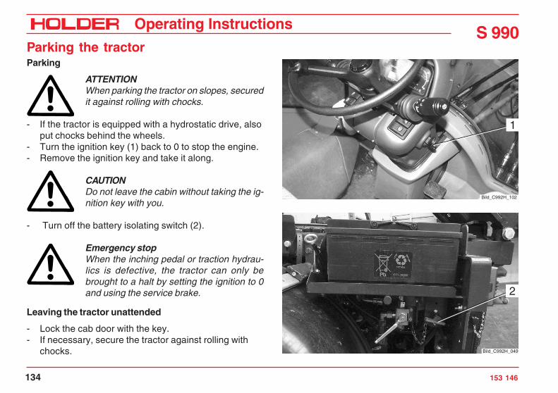
S 990Operating Instructions
134 153 146
Parking the tractorParking
ATTENTIONWhen parking the tractor on slopes, securedit against rolling with chocks.
- If the tractor is equipped with a hydrostatic drive, alsoput chocks behind the wheels.
- Turn the ignition key (1) back to 0 to stop the engine.- Remove the ignition key and take it along.
CAUTIONDo not leave the cabin without taking the ig-nition key with you.
- Turn off the battery isolating switch (2).
Emergency stopWhen the inching pedal or traction hydrau-lics is defective, the tractor can only bebrought to a halt by setting the ignition to 0and using the service brake.
Leaving the tractor unattended
- Lock the cab door with the key.- If necessary, secure the tractor against rolling with
chocks.
1
Bild_C992H_102
2
Bild_C992H_049

Operating Instructions
153 146 135
S 990
Trailers, towingYour tractor can tow the following trailers:
Table of trailers
The following trailer combinations are allowed:1 Tractor with single-axle trailer with brakes or without brakes.2 Tractor plus single-axle trailer with brake or without brake plus 2-axle trailer with override brake.3 Tractor plus two-axle trailer with brake plus 2-axle trailer with override brake.4 Tractor plus two trailers with override brakes, one single-axle trailer plus one 2-axle trailer, or one 2-axle trailer plus one
single-axle trailer.
NOTEThe total length of the tractor-trailer train must not exceed 18 m.
Type of trailer Max. total weight Brake system
Single axle trailers 2.5 t without brake system
Single and multiple axle trailers Up to 4 tWith own brake system if the trailer brake levercan be mounted easily accessible beside thedriver's seat
Single axle trailers Up to 4.5 t With overrunning brakes
Multiple axle trailers Up to 4.5 t With service brake system andparking and rapid emergency brake system
Trailers Up to 12 t With hydraulic or pneumatic brake system

S 990Operating Instructions
136 153 146
Trailers, towingOperating the trailer coupling, attaching trailers
- Adjust the height of the trailer coupling (2) at theadjustment rail (1) so that the trailer tiller can beattached horizontally.
- To adjust the height, pull the lever (6) up.
Tongue weightATTENTIONThe tongue weight must be at least 25 kg(4 % of the trailing load), while the maximumtongue weight must not exceed 800 kg. Ifthe tongue weight is less or exceeded whenunloading the trailer, the load must be shiftedso that the tongue weight returns to the per-missible range.
- Drive the tractor in front of the trailer to be attached.
DANGERThe trailer must be secured against uninten-tional movement (rolling).
- Pull the release lever (4) up until the tow pin (3)releases the coupling jaw.
DANGERNever allow anyone to stand between the trac-tor and trailer.
- Reverse the tractor until the trailer tongue is in thecoupling jaw. The coupling will close upon contact andthe tow pin (3) will go through the eye in the trailertongue.
DANGERThe trailer coupling must close fully.
- Connect the trailer lighting to the socket (5).- Remove the wheel chocks from the trailer.
Bild_105
5
4
321
6

Operating Instructions
153 146 137
S 990Trailers, towing
Driving with a trailer
- Turn the speed range knob (1) to position S or L. Thetractive force is greatest in position L.
- Drive the tractor as described in the section entitled„Driving“.
DANGERIf a trailer not requiring a permit is attached,the ground speed is limited to 25 km/h. Thetrailer must be identified with a 25 km/h sign.
Bild_S 990_003
1

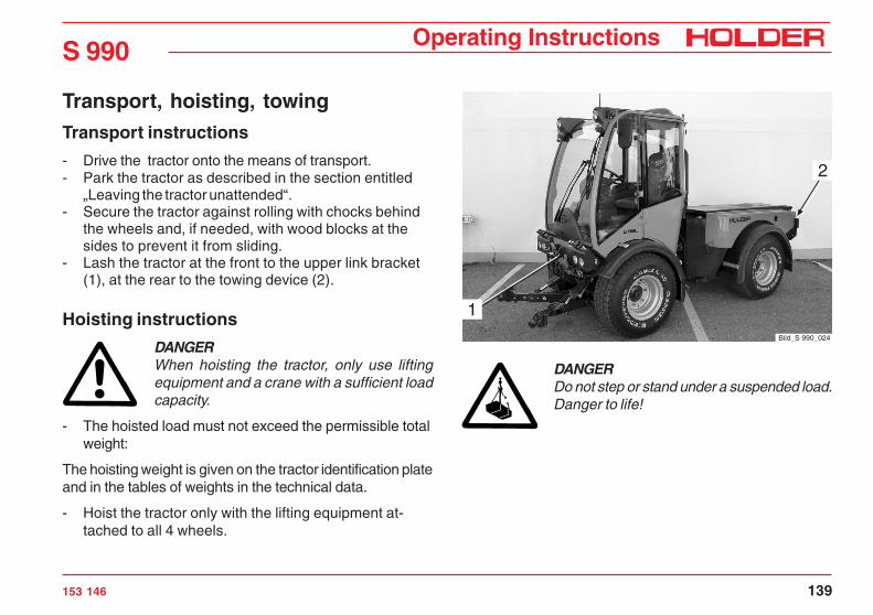
Operating Instructions
153 146 139
S 990
Transport, hoisting, towingTransport instructions
- Drive the tractor onto the means of transport.- Park the tractor as described in the section entitled
„Leaving the tractor unattended“.- Secure the tractor against rolling with chocks behind
the wheels and, if needed, with wood blocks at thesides to prevent it from sliding.
- Lash the tractor at the front to the upper link bracket(1), at the rear to the towing device (2).
Hoisting instructions
DANGERWhen hoisting the tractor, only use liftingequipment and a crane with a sufficient loadcapacity.
- The hoisted load must not exceed the permissible totalweight:
The hoisting weight is given on the tractor identification plateand in the tables of weights in the technical data.
- Hoist the tractor only with the lifting equipment at-tached to all 4 wheels.
DANGERDo not step or stand under a suspended load.Danger to life!
Bild_S 990_024
1
2

S 990Operating Instructions
140 153 146
Transport, hoisting, towingTowing instructions
If your tractor can not drive on its own power because ofdamage, it can be towed. Use the trailer coupling or thefront upper link bracket on the cabin for towing.
DANGERThe towing tractor must have sufficient trac-tive and braking force for the towed load with-out brakes.
- The towed load must not exceed the allowed maxi-mum total weight.The total weight of the tractor is given on the identifi-cation plate and in the tables of weights in the techni-cal data.
- Attach the towing device (only a rigid tow bar in caseof a brake malfunction) to the trailer coupling (1).
- Turn on the ignition.- Turn off the parking brake switch.- Set the direction switch to the centre position (no
direction of travel selected).- Turn the speed range knob to the zero position (centre
position).- Let the engine run so that the power steering is in
operation.
CAUTIONIf the engine is not running during towing or ifthe hydraulic system has failed, steering willbe difficult. Increased steering effort will berequired in this case.
- Tow the tractor at 10 km/h maximum to the nearestservice centre.
- Park the tractor and secure it against rolling.
1
Bild_S 990_025
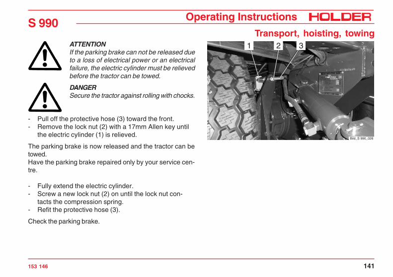
Operating Instructions
153 146 141
S 990Transport, hoisting, towing
ATTENTIONIf the parking brake can not be released dueto a loss of electrical power or an electricalfailure, the electric cylinder must be relievedbefore the tractor can be towed.
DANGERSecure the tractor against rolling with chocks.
- Pull off the protective hose (3) toward the front.- Remove the lock nut (2) with a 17mm Allen key until
the electric cylinder (1) is relieved.
The parking brake is now released and the tractor can betowed.Have the parking brake repaired only by your service cen-tre.
- Fully extend the electric cylinder.- Screw a new lock nut (2) on until the lock nut con-
tacts the compression spring.- Refit the protective hose (3).
Check the parking brake.
321
Bild_S 990_026


Operating Instructions
153 146 143
S 990
Indicators, adjustments
Adjusting the speedometer
The adjustment of the speedometer in the multifunctionaldisplay is required when changing from larger to smallertires and vice versa.
Please refer to the maintenance instructions for the adjust-ment of the speedometr.
Indication of special operating conditions
The built-in horn also warns the driver of the following con-dition:
- clogged air filter.
The acoustic warning signal warns the driver of the follow-ing conditions (only with the engine running):
- urn signal lights- Hazard warning flasher- Differential lock- Coolant temperature > 110°C- Low engine oil pressure- Parking brake applied - only when driving
The LED behind the seat indicates a defect in the tractionelectronics.


Operating Instructions
153 146 145
S 990
Malfunctions, causes, remedyThe following tables list malfunctions and their possiblecauses. If you can not carry out the remedial measure your-self, please contact a service centre or our customer serv-ice.The optional test and control box BB3 or the Bodem PCsoftware is available for further troubleshooting/diagnosis/traction electronics calibration.
Engine and exhaust gas turbocharger mal-functions
Please observe the notes in the operating instructions forthe engine.
Traction electronics and traction hydraulicsmalfunctions
Malfunction Cause Remedy
Traction electronics in general Traction electronics defectiveThe warning light is illuminated orflashes if the following conditions arefulfilled:
• Ignition on• Driving program switch at 1, 2, 3 or
4• Direction switch in neutral position
Read out fault history with BB3 orBodemEliminate the faultClear the fault in the error memory

S 990Operating Instructions
146 153 146
Malfunctions, causes, remedyMalfunction Cause Remedy
Tractive force too low Fault in the feed pressure or highpressure system
Check the feed pressure of hydraulic system
Check the high pressure hydraulic system
Check for leakage at variable pump andvariable motor
Check the variable pump controls andproportional solenoids
Check the maximum current atproportional solenoids
Eliminate determined faults
No forward and reverse travel Direction switch in neutral position
Machine was started with direction oftravel preselected
Electronics without electrical power
Traction electronics defective
Electrical connection to the variablepump is interrupted
Put the direction switch to the desireddirection of travel
Put direction switch in neutral position andpreselect desired direction of travel
Check the fusesCheck the electrical connection
Read out fault with BB3 or Bodem andeliminate fault
Make a connection

Operating Instructions
153 146 147
S 990Malfunctions, causes, remedy
Malfunction Cause Remedy
No forward and reverse travel Electrical connection of diesel enginespeed sensor interrupted, possiblyoxidized
Speed range knob in neutral position
Direction switch defective or badcontact
Driving program switch at 0
Fault in the feed pressure or highpressure system
Make a connection
Select the working or transport range
Renew the direction switch,make contact
Select the desired driving programCheck the feed pressure of hydraulicsystem
Check the high pressure hydraulic system
Check the variable pump controls andproportional solenoids
Eliminate determined faults
No maximum speed Diesel engine does not attainmaximum RPM
Inch pedal not at maximum speed
Variable pump or variable motor doesnot swash fully to end position
Inductive transmitter on variable motordefective, possibly electricalconnection adjustment
Check the accelerator linkageCheck the diesel engine
Adjust, calibrate the inch potentiometer
Check the maximum current,
Check the proportional solenoidCheck the inductive transmitter, renew ifnecessary. Check the electrical connection
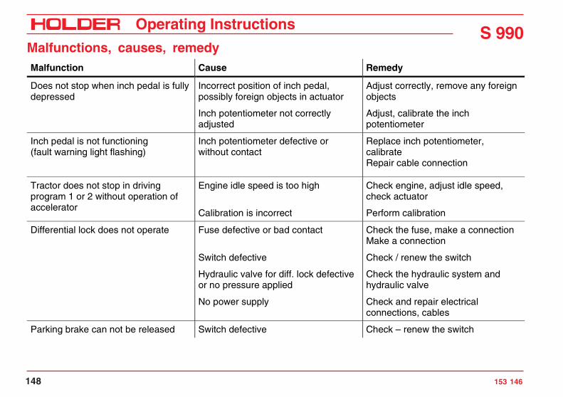
S 990Operating Instructions
148 153 146
Malfunctions, causes, remedyMalfunction Cause Remedy
Does not stop when inch pedal is fullydepressed
Incorrect position of inch pedal,possibly foreign objects in actuator
Inch potentiometer not correctlyadjusted
Adjust correctly, remove any foreignobjects
Adjust, calibrate the inchpotentiometer
Inch pedal is not functioning(fault warning light flashing)
Inch potentiometer defective orwithout contact
Replace inch potentiometer,calibrateRepair cable connection
Tractor does not stop in drivingprogram 1 or 2 without operation ofaccelerator
Engine idle speed is too high
Calibration is incorrect
Check engine, adjust idle speed,check actuator
Perform calibration
Differential lock does not operate Fuse defective or bad contact
Switch defective
Hydraulic valve for diff. lock defectiveor no pressure applied
No power supply
Check the fuse, make a connectionMake a connection
Check / renew the switch
Check the hydraulic system andhydraulic valve
Check and repair electricalconnections, cables
Parking brake can not be released Switch defective Check – renew the switch

Operating Instructions
153 146 149
S 990Malfunctions, causes, remedy
Hydraulic and steering system malfunctions
NOTEThese notes only apply for valve arrange-ments conforming to our circuit diagrams orapproved by Bucher Hydraulics.
Malfunction Cause Remedy
Power lift or hydraulic cylinder is notlifting. No build-up of pressurediscernible (steering workingnormally).
Slide valve in input plate jammeddue to foreign particles
Remove and clean slide valve ininput plate LU8SSCS-OM22/04!Do not change the pressure setting!
Power lift is lifting too little. Pressure setting too low
Oil level too low
Reset the pressure with a pressuregauge (190 bar).
Add the specified oil type.
Operating pressure is only achievedat high RPM.
Pump defective Replace the pump
Power lift is not liftingInsufficient power,drops after operation.
Lift cylinder leakingValve leaking
Clean / renew

S 990Operating Instructions
150 153 146
Malfunctions, causes, remedyMalfunction Cause Remedy
Hydraulic oil overheats quickly,system working against excesspressure.(engine under load)
Cylinder at limit stop
Attachment is not connected, butjoystick is in work position (quickcoupler)
Move joystick to neutral position(free circulation)
Move joystick to neutral position(free circulation)
Oil is foaming Leak in the suction area Inspect all line fittings and tighten, ifnecessary
Hydraulic system is working tooslowly, whistling noise
Hydraulic oil level too low
Temperatures too low
Add oil as specified
Fill proper oil type according tomaintenance instructions
Steering is not working Priority valve contaminated
Relief valve in power steering notclosing
Clean priority valve (mounted on theframe at the right)
Remove and clean (service centre)
Lost steering motion when steeringdirection is changed fast
Leak in the steering return line Inspect the hose connections

Operating Instructions
153 146 151
S 990Malfunctions, causes, remedy
Working hydraulics malfunctions
The optional OPUS test unit or a PC software is availablefor further troubleshooting/diagnosis/working hydraulics elec-tronics calibration.
NOTEThese notes only apply for valve arrange-ments conforming to our circuit diagrams orapproved by Bucher Hydraulics.
Malfunction Cause Remedy
All hydraulic functions not active Controller unit (box) without power
Plug or cable harness defective
Controller unit defective,Observe flashing code of the LEDon he box
Turn on master switch (toggle switch)
Repair or replace plug, cable
Replace controller unit
Individual functions not active Function is locked
Plug or cable damaged
Solenoid or valve defective
Release with Opus or PC software,also refer to Bucher operatinginstructions.
Repair or replace
Repair or replace

S 990Operating Instructions
152 153 146
Malfunctions, causes, remedyMalfunction Cause Remedy
Joystick inoperative Joystick locked
Buttons defective
Release with Opus or PC software
Determine fault with Opus, submit thejoystick for repair, or replace it
Membrane keyboard inoperative Mechanically or electricallydefective
Determine fault with Opus or PCsoftware, replace membrane keyboardand/or related printed circuit board
Simultaneous failure of many joystickand membrane keyboard functions
Power supply interrupted(3 separate positive cables, pin 05,23, 34)
Determine and eliminate the defect(cable breakage, contact problems inthe plug) Attention: Although voltage isapplied in the quiescent state, powerfailure can result during operation
Functions operate too slowly or toofast
Flow rate limiting out of adjustment
Current value for a certain channeltoo low
Readjust with hash (#) key and joystickor Opus or PC software
Adjust from 800 to 1900 mA in"Channels" area with Opus or PCsoftware
4th control level on joystick"malfunctioning"
Special function activated withasterisk (*) key
Push the asterisk (*) key again
Joystick or membrane keyboard notfunctioning
Bus cable is defective (Opus doesnot indicate a connection)
Make a connection or replace thecable
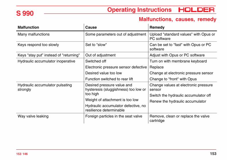
Operating Instructions
153 146 153
S 990Malfunctions, causes, remedy
Malfunction Cause Remedy
Many malfunctions Some parameters out of adjustment Upload "standard values" with Opus orPC software
Keys respond too slowly Set to "slow" Can be set to "fast" with Opus or PCsoftware
Keys "stay put” instead of "returning" Out of adjustment Adjust with Opus or PC software
Hydraulic accumulator inoperative Switched off
Electronic pressure sensor defective
Desired value too low
Function switched to rear lift
Turn on with membrane keyboard
Replace
Change at electronic pressure sensor
Change to "front" with Opus
Hydraulic accumulator pulsatingstrongly
Desired pressure value andhysteresis (sluggishness) too low ortoo high
Weight of attachment is too low
Hydraulic accumulator defective, noresilience determinable
Change values at electronic pressuresensor
Switch the hydraulic accumulator off
Renew the hydraulic accumulator
Way valve leaking Foreign particles in the seat valve Remove, clean or replace the valvecartridge

S 990Operating Instructions
154 153 146
Malfunctions, causes, remedy
Troubleshooting also with Opus (Order No. 204-80-70) or PCsoftware in the menu• Keyboard check: keys of the membrane keyboard.• Output functions: functions XO...Y3, check if box
provides current for valves.• Hydraulic accumulator: functions of the hydraulic
accumulator.• Specified value channel.• FCE1: Joystick functions.• Diagnosis of master inputs.• Diagnosis of BKN nodes.
Malfunction Cause Remedy
No build-up of pressure Slide valve in input plate is stuck(foreign particles)
Remove, clean or plate replace theslide valve
Strong flow rate fluctuation or too littleflow of priority flow valve I
Low oil flow Increase RPM, reduce consumption of2nd load

Operating Instructions
153 146 155
S 990
General remarks on maintenanceIn order to always keep your tractor operational, we ask youto read these maintenance instructions carefully. This sec-tion contains all the information required for careful mainte-nance and care of your tractor. Take particular care to haveyour tractor serviced at the intervals stated in the mainte-nance schedule.
Service
Please have all services (acc. to the maintenance sched-ule) and repairs on your tractor done regularly by your dealer(service centre) and confirmed with a stamp and signaturein the service book.Detach the double guarantee card, have it filled in by thedealer and send it with the customer’s signature directly to:
Max Holder GmbHP. O. Box 15 5572545 Metzingen/Wuertt.
Warranty and product liability can only be claimed if themaintenance services and inspections have been carriedout punctually and regularly.
Qualification of service personnel
The tractor, including the attachments, may only be serv-iced and repaired by persons who are familiar with it andwho have been instructed in the hazards involved.The qualified personnel entrusted with the work must havethe required tools.The applicable safety regulations and rules must be ob-served.
How to value the tractor?
As you know, a car is judged by its age together with thenumber of kilometres driven. Tractors are best assessedaccording to service hours and age, whereby the followingguidelines can be assumed:
Service hours Kilometres driven1 50
10 500
150 7500
300 15000
600 30000
1500 75000

S 990Operating Instructions
156 153 146
General remarks on maintenanceHandling fuel, fluids and lubricants
• Fuels, fluids and lubricants must always be handledproperly and as specified by the manufacturer.
• Fuels, fluids and lubricants may only be stored inapproved containers at specified places of storage.They can be inflammable, therefore do not allow themto come in contact with hot objects or with nakedflames.
• Exercise caution when handling fuels. Increased dan-ger of fire! Do not fill fuels in the vicinity of naked flames,ignition sparks or hot engine parts. No smoking whenrefuelling!
• Before refuelling, shut off the engine and remove theignition key. Do not refuel in enclosed spaces. Do notspill fuels! (Use suitable filling aids).
• Exercise caution when handling brake fluid and batteryacid (poisonous and corrosive).
• Only use clean vessels when filling fuel, fluids andlubricants.
• When using fuels, fluids, lubricants and cleaners, followthe safety and disposal instructions of the manufactur-er.
• Always avoid spilling of the product. Eliminate spilledbrake fluid immediately with a suitable binding agentand discard as specified by regulations.
• Oils, fuels, batteries, brake fluid and filters must bedisposed of separately and as specified by regulations.
• Before beginning lubrication, changing filters or openingthe hydraulic system, clean the area surrounding theaffected part carefully.
• Replaced parts must be discarded in a way friendly tothe environment.
• Observe all local and national laws and regulations.
CAUTIONThe penetration of hydraulic oil under pres-sure into the skin, eg due to leaks, is danger-ous. If such injuries occur, seek medical aidat once.
Safety notes for maintenance
Observe the notes in these maintenance instructions andthe general applicable safety and accident prevention rules!• Do not allow anyone to stand around where they might
get hurt!• When starting the engine, the traction and attachment
drives must be shut off!• Start the engine only from the driver’s station. Do not
start the engine by short circuiting the starter terminals,as the machine could start moving immediately.

Operating Instructions
153 146 157
S 990General remarks on maintenance
• Do not run the engine in enclosed spaces! Danger ofpoisoning!
• To prevent the danger of fire, always keep the tractorand attachments clean!
• When leaving the tractor unattended, secure it againstrolling and unauthorized use (parking brake, chocks),stop the engine, remove the ignition key and lock thecabin, if necessary!
• Never leave the tractor unattended if the engine is stillrunning!
• If external electric power loads are connected (egequipment with solenoid valves), protect them withdiodes against back currents. If not, the traction elec-tronics could be affected.
• Operate the equipment only if all guards are installedand in position.
• Install and remove the articulated shaft only with theengine stationary.
• When working with the PTO, no-one should be standingin the area of the rotating PTO and articulated shaft.
• The guards for the articulated shaft and the PTOs mustbe installed as specified.
• When the articulated shaft is removed, refit the protec-tive cap on the PTO.
• Do not do any welding, cutting and grinding on support-ing parts and other safety-relevant parts such as thetractor frame, axles, trailer coupling, etc.
• Before doing electric welding, disconnect all connec-tors from the electronic system.
• The mounting of tires requires sufficient knowledge andspecified mounting tools.
• Only use genuine HOLDER replacement parts! Use theparts listed in the list of replacement parts in the sectionentitled „Maintenance data“.
• Always check the tractor and the attachment for road-worthiness and operating safety before taking the trac-tor into operation and after maintenance or repair serv-ices!

S 990Operating Instructions
158 153 146
General remarks on maintenanceDoing work on the electrical equipment
Before doing work on the electrical equipment, cut off thepower with the battery isolating switch (1).
- The switch must be in the vertical position and thetoggle removed.
CAUTIONDisconnect the battery ground lead (2).
Do not place any metal parts on the battery terminals. Riskof short circuit!
Bild_C992H_070
2
1

Operating Instructions
153 146 159
S 990General remarks on maintenance
Jack lift points
Jacking up
DANGERWhen operating the lift jack, make sure thatthe tractor is parked securely and preventedfrom rolling (chock)!
The tractor may only be jacked up at the shown locations (1and 2).
DANGERThe weight to be lifted should not exceed themaximum load capacity of the jack.
When doing repairs, the raised tractor must also be securedagainst lowering with assembly stands. Place the standsunder the axles on both sides.
Bild_S 990_050
1
2 Bild_S 990_051

S 990Operating Instructions
160 153 146
General remarks on maintenanceSecuring the dumping subframe (dumpbody)*
The dumping subframe (dump body*) must be securedagainst accidental lowering during all services for which itmust be raised.
- Place the U-channel on the cylinder and secure it witha locking pin (1).
* Option
Bild_C992H_062
1

Operating Instructions
153 146 161
S 990General remarks on maintenance
Tilting the cabin
The cabin can be tilted for repair and maintenance serv-ices.
ATTENTIONRaise the cabin carefully.
- Remove the nuts (1) and holding plate at the back ofthe cabin.
- Attach an M14 eyebolt* (2) to the cabin frame at thetop.
- Attach a hook or rope and slowly lift the cabin with ahoist.
- Take the prop rod (3) out of the mounting, insert it onthe tractor frame and secure it with a securing pin (4).
DANGERWorking under the cabin is only allowed withthe prop rod in place.
* Option (commercial good) Bild_C992H_10343
4
2
1 Bild_S 990_032


Operating Instructions
153 146 163
S 990
Maintenance schedule
Maintenance during the initial period of operation
Interval Service and inspection See pageMaintenance after thefirst 50 service hours
Check the engine for leaksCheck the air tubes and air hoses for leaksCheck the heating hoses for damage and tightnessCheck the coolant level, top up if necessaryCheck the V-belt for tension and condition, tighten orreplace belt if necessaryCleaning the strainer in the fuel pump, replace if necessaryCheck the hydraulic lines and hoses for damage andtightnessCheck the hydraulic oil levelReplace the working hydraulics pressure filterReplace the traction hydraulics pressure filterChange the front and rear gearbox oilCheck the service brakeCheck the parking brake for proper operationTighten the wheel nuts (340 Nm)Tighten nuts and bolts according to the torque table
169169171170
197171
17248173174175

S 990Operating Instructions
164 153 146
Maintenance schedule
The services and inspections specified below must be car-ried out when the stated number of service hours is reached.The services and inspections of the lower intervals must becarried out at the same time.
Example:At 1000 hours of operation, the services and inspectionsfor 500 and 250 service hours must also be carried out.
Regular maintenance
Interval Service and inspection See pageMaintenance after thefirst 500 service hours
Clean the working hydraulics suction filter, replace if necessaryClean the suction filter for the traction hydraulics/attachmentvariable pump, replace if necessaryReplace the working hydraulics pressure filterReplace the traction hydraulics pressure filterChange the hydraulic oilChecking the engine valve clearances
183183
173174182
Interval Service and inspectionMaintenance as required Adjust the speedometer
Check the air cleaner system, clean if necessaryReplace the hydraulic return filter for attachment variable pumpReplace the hydraulic return filter for hydraulic systemCheck the radiator, clean if necessaryCheck the air conditioner condenser for free flow of air, clean if necessaryClean the fresh air filter and filter mat, replace if necessaryGrease the tractor (except universal joints)Check the frost protection of the windshield washer water

Operating Instructions
153 146 165
S 990Maintenance schedule
Periodic maintenanceInterval Service and inspectionMaintenance every 250 service hours Check the engine for leaks
Check the engine oil levelCheck the air tubes and air hoses for leaksCheck the heating hoses for damage and tightnessCheck the radiator, clean if necessaryCheck the coolant concentration, add antifreeze if necessaryCheck the coolant level, top up if necessaryCheck the V-belt for tension and condition, tighten or replace if necessaryCheck the fuel lines for condition and tightnessCheck the cable connectionsCheck the hydraulic lines and hoses for damage and tightnessCheck the steering cylinder for leaks and mechanical damagesCheck the hydraulic oil levelCheck the front and rear gearbox for leaksCheck the front and rear gearbox oil levelChecking the speed range selector for ease of shiftingCheck the brake fluid levelCheck the service brakeCheck the parking brake for proper operationCheck the heating system for proper operationCheck the air conditioner for proper operationCheck the sight glass of the air conditioner for the formation of bubblesCheck the condenser for the free flow of air, clean if necessaryCheck the seat of the compressorCheck the V-belt of the compressor for proper tension and condition

S 990Operating Instructions
166 153 146
Maintenance schedulePeriodic maintenanceInterval Service and inspectionMaintenance every250 service hours
Check the condensate water drainVisual inspection of air conditioner for leaksCheck the air conditioner hoses and wiring for damageClean the fresh air filter and filter mat in the fan box, replace if necessaryCheck the electrical system for proper operationCheck the lightsCheck the preheating systemLubricate the tractor (except universal joints)Check the accelerator for ease of movement, clean and grease if necessaryCheck the windshield washer water level, top up if necessaryCheck the frost protection of the windshield washer waterCheck the windscreen wiper, renew if necessaryTighten the wheel nuts (340 Nm)Tighten nuts and bolts according to the torque tableCheck the tyre inflation pressure
Maintenance every500 service hours
Change the engine oil incl. oil filter (at least once a year)
Maintenance every1000 service hours
Check the engine valve clearancesCheck the glow plugsReplace the fuel filter elementClean the strainer in the fuel pump, replace if necessaryLubricate the universal joints (at least once a year)

Operating Instructions
153 146 167
S 990Maintenance schedule
Periodic maintenanceInterval Service and inspectionMaintenance every1500 service hours
Hydraulic oil change of HE oils (at least every 2 years)Hydraulic oil change of mineral oils (at least every 2 years)Clean the suction filter of the traction and working hydraulics, replace ifnecessary (at least every 2 years)Clean the suction filter for the traction hydraulics/attachment variable pump,replace if necessary (at least every 2 years)Replace the working hydraulics pressure filter (at least every 2 years)Replace the traction hydraulics pressure filter (at least every 2 years)Replace the return filter of the attachment variable pump or power hydraulic systemChange the front and rear gearbox oil
Maintenance every3000 service hours
Change the toothed belt (at least every 5 years)Replace the injection nozzles
Annual maintenance Change the engine oil incl. oil filter cartridgeChange the air filter elementChange the brake fluidChange the fresh air filterCheck the battery, coat the terminals with greaseLubricate the universal joints

S 990Operating Instructions
168 153 146
Maintenance schedulePeriodic maintenance
Interval Service and inspectionMaintenance every 2 years Change the coolant
Replace the V-beltChecking the glow plugsHydraulic oil change of HE oils (or at 1500 hours)Hydraulic oil change of mineral oils (or at 1500 hours)Clean the suction filter of the working hydraulics, replace if necessary (orat least every 1500 hours)Clean the suction filter for the traction hydraulics/attachment variablepump, replace if necessary (or at 1500 hours)Replace the working hydraulics pressure filter (or at 1500 hours)Replace the traction hydraulics pressure filter (or at 1500 hours)Replace the alternator and the water pump V-beltReplace the air conditioner V-belt
Maintenance every 5 years Change the toothed belt (or at 3000 hours)

Operating Instructions
153 146 169
S 990
Maintenance during the initial periodof operationThe following services and inspections are due during theinitial period of operation:
Maintenance after the first 50 service hoursMaintenance after the first 500 service hours
Maintenance after the first 50 servicehours
Checking the engine for leaks
- Raise the dumping subframe (dump body*) andsecure it against accidental lowering.
- Check the engine and attachments for leaks.
Checking air tubes and air hoses for leaks
- Check the air tubes and air hoses (1) for damage andleaks.
Bild_S 990_0331* Option

S 990Operating Instructions
Maintenance after the first 50 service hours
170
Checking the coolant level, topping up ifnecessary
- Park the tractor on a level surface.- Raise the dumping subframe and secure it against
accidental lowering.- Turn off the engine and allow it to cool.
The coolant level should be between the min. and max. markson the expansion reservoir (4) when the engine is cool.
Add coolant if the coolant level is below the min. mark.
ATTENTIONDo not remove the cap when the engine ishot. Danger of scalding!
- Remove the cap (3) on the expansion reservoir (4)and add coolant.
Observe the mixing ratio of anti-freeze/cooling water.
- Refit the cap (3).
If there is no more coolant in the expansion reservoir, theradiator (2) must first be filled fully with coolant.
ATTENTIONDo not remove the cap when the engine ishot. Danger of scalding!
- Remove the cap (1) and top up the radiator (2) withcoolant.
- Refit the cap (1).- Remove the cap (3) of the expansion reservoir (4) and
fill coolant up to the max. mark.- Refit the cap (3).- Check the coolant level again, adding coolant if
necessary.- Lower the dumping subframe.
Bild_S 990_034
1 2
3
4
Operating InstructionsS 990Maintenance after the first 50 service hours
153 146 171
Checking the heating hoses for damage andtightness
- Check the heating hoses for leaks and damage.
Checking engine V-belt tension and condi-tion
Please also refer to the operating instructions of the enginemanufacturer.
CAUTIONAdjust V-belt tension only when the engine isshut off.
- Inspect V-belts for cracks and tears over their entirelength.
- Replace damaged V-belts.- Using thumb pressure, check that belt deflection is
not over 10 - 15 mm.- To tighten the V-belt: Loosen the fastening screws on
the idler pulley mounting and push the pulley outwardsuntil the proper V-belt tension is obtained.
- Tighten the fastening screws on the idler pulleymounting.
Cleaning the strainer in the fuel pump, re-placing if necessary
- Clean the strainer and, if necessary, replace it accor-ding to the procedure in the engine operating instruc-tions.

S 990Operating Instructions
Maintenance after the first 50 service hours
172
Checking the hydraulic lines and hoses forleaks and damage
- Check all hydraulic lines and hoses for leaks anddamage.
Checking the hydraulic oil level
- Check the hydraulic oil level (see page 48).
Bild_C992H_081

Operating InstructionsS 990Maintenance after the first 50 service hours
153 146 173
Replacing the working hydraulics pressurefilter
- Depressurize the hydraulic system by operating thejoystick.
- Remove the air filter housing (1) with a 24mm wrench.
ATTENTIONObserve the instructions for handling fuel, flu-ids and lubricants!
- Clean the mating surface of the filter mount.- Withdraw the pressure filter from the housing.- Clean the housing.- Coat the new gasket with oil.- Insert the new pressure filter in the air filter housing.- Using a new gasket, screw the air filter housing into
the filter mount.- Check for leaks.- Check the hydraulic oil level.
Bild_S 990_035
1
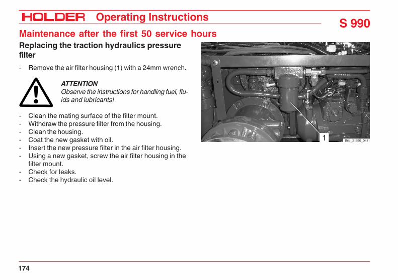
S 990Operating Instructions
Maintenance after the first 50 service hours
174
Replacing the traction hydraulics pressurefilter
- Remove the air filter housing (1) with a 24mm wrench.
ATTENTIONObserve the instructions for handling fuel, flu-ids and lubricants!
- Clean the mating surface of the filter mount.- Withdraw the pressure filter from the housing.- Clean the housing.- Coat the new gasket with oil.- Insert the new pressure filter in the air filter housing.- Using a new gasket, screw the air filter housing in the
filter mount.- Check for leaks.- Check the hydraulic oil level.
Bild_S 990_0471

Operating InstructionsS 990Maintenance after the first 50 service hours
153 146 175
Changing the front and rear gearbox oil
Changing the front gearbox oil (including axle)
NOTEChange the gear oil only when at operatingtemperature.
- Park the tractor on a level surface.- Remove the filler plug (1) at the front gearbox and
clean it with diesel oil.- Place a suitable catch pan beneath the gearbox and
axles.
CAUTIONDanger of scalding when draining hot gearoil.
- Remove the oil drain plug (2) at the front gearbox andwash it with diesel oil.
- Remove the drain plugs (3) and clean them with dieseloil.
- Allow the oil to drain completely.- Refit the oil drain plugs with new sealing rings. Make
sure that the plugs are tight.
Bild_C992H_066
33
2
Bild_S 990_036
1
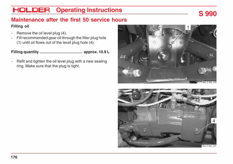
S 990Operating Instructions
Maintenance after the first 50 service hours
176
Filling oil
- Remove the oil level plug (4).- Fill recommended gear oil through the filler plug hole
(1) until oil flows out of the level plug hole (4).
Filling quantity ....................................... approx. 10.9 L
- Refit and tighten the oil level plug with a new sealingring. Make sure that the plug is tight.
4
Bild_S 990_037
Bild_S 990_036
1

Operating InstructionsS 990Maintenance after the first 50 service hours
153 146 177
Changing the gear oil of the rear gearbox (includingoffset axles)
NOTEChange the gear oil only when at operatingtemperature.
- Park the tractor on a level surface.- Unscrew the filler plug (1) at the rear gearbox and
wash it with diesel oil.- Place a suitable catch pan under the gearbox.
CAUTIONDanger of scalding when draining hot gearoil.
- Remove the oil drain plug (2) at the rear gearbox andclean it with diesel oil.
- Allow the oil to drain completely.
Bild_163
1
2 Bild_190

S 990Operating Instructions
Maintenance after the first 50 service hours
178
- Refit the drain plug with a new sealing ring. Make surethat the plug is tight.
- Fill recommended gear oil through the filler plug hole.
Filling quantity ......................................approx. 17.75 L
- Check the oil level at the sight glass (3).- The oil level must be visible in the sight glass.- Then fill another 3 litres of gear oil.
Bild_C992H_056
3

Operating InstructionsS 990Maintenance after the first 50 service hours
153 146 179
Bild_C992H_05212
Checking the parking brake for proper op-eration
DANGERDo not operate the tractor with a defectivebraking system!
- Operate the parking brake (2).- Select driving speed range 1 or 2 and start off slowly.
A noticeable resistance should be discernible whenstarting off and an acoustic warning signal shouldsound.
Check the service brake
CAUTIONOperating the service brake pedal (1) willbrake the tractor strongly.
- Depress the brake pedal (1) while driving slowly. Thetractor should brake strongly.
DANGERIn case of irregularities with the braking sys-tem, stop the tractor immediately and have itchecked by your service centre.

S 990Operating Instructions
Maintenance after the first 50 service hours
180
Tightening the wheel nuts
- Tighten all wheel nuts at the front and rear wheels (1and 2).
Torque ................................................................ 340 Nm
- Have any damaged parts replaced by your servicecentre.
Tightening nuts and bolts according to the torquetable
- Tighten the nuts and bolts at the variable pumps,axles and engine.
- Tighten the nuts and bolts to the specified torqueaccording to tables in the maintenance data.
Bild_S 990_038
2
1

Operating Instructions
153 146 181
S 990
Maintenance after the first 500service hours
Replacing the working hydraulics pressurefilter
- Refer to page 173 of maintenance after the first 50service hours.
Replacing the traction hydraulics pressurefilter
- Refer to page 174 of maintenance after the first 50service hours.

S 990Operating Instructions
182 153 146
Maintenance after the first 500 service hours
Bild_139
1
Replacing the hydraulic oil of the tractionand working hydraulic system
ATTENTIONWhen using mineral hydraulic oils, the oil mustbe changed for summer and winter operation.Refer to the coolant, fuel and lubricant speci-fications on page 221.
NOTEChange the hydraulic oil only at operatingtemperature.
- Park the tractor on a level surface. Raise the dumpingsubframe.
CAUTIONSecure the dumping subframe (dump body*)against accidental lowering.
- Place a suitable catch container beneath the hydraulicoil tank.
- Depressurize the hydraulic system by operating thejoystick.
- Retract all hydraulic cylinders.
CAUTIONDanger of scalding when draining hot hydraulicoil.
- Unscrew the oil drain plug (1).- Drain the oil.
Dispose of the oil in an environment-friendly way.
- If necessary, flush the hydraulic oil tank with cleanhydraulic oil.
* Option

Operating Instructions
153 146 183
S 990Maintenance after the first 500 service hours
Cleaning the suction filters of the tractionand working hydraulics, replacing if neces-sary
- Remove the pin (3) of the hydraulic cylinder (4).- Remove the banjo bolts (2).- Remove the filter cover fastening screws (1).- Pull out the filter housings with the star filter.
ATTENTIONObserve the instructions for handling fuel, flu-ids and lubricants!
Cleaning:
- Wash the star filters with clean diesel oil and blow outwith compressed air.
Replacement:
- Unscrew the star filters from the filter housing with a46mm open-ended wrench.
- Screw new filters on the filter housing, using newrubber toric rings.
Installation is in the reverse order of removal.
Bild_C992H_0824 3
21
1
2

S 990Operating Instructions
184 153 146
Maintenance after the first 500 service hours- Refit the drain plug with a new sealing ring. Make sure
that the plug is tight.- Fill recommended hydraulic oil through the filler neck (2).
Filling quantity .......................................... approx. 45 L
- Check the oil level at the sight glass (3).- Refit the filler neck cap.- Start the engine. Operate the working hydraulic and
steering systems.
NOTEThe hydraulic system is vented automatically.
- Shut off the engine and depressurize the hydraulicsystem.
- Check for leaks.- Check the oil level at the sight glass (3). Add hydrau-
lic oil if necessary.
Checking the engine valve clearances
- See page 205 of maintenance every 1000 servicehours.
Bild_C992H_059
2
Bild_C992H_060
3

Operating Instructions
153 146 185
S 990
Maintenance as required
Adjusting the speedometer
The adjustment of the speedometer in the multifunctionaldisplay is required when changing from larger to smallertires and vice versa.- Carefully pull the multifunctional display (1) out at the
left and right side and rotate it.- Remove the cover from the DIP switch (2) on the
back.- Set the 6 of 8 toggle switches to the positions shown
in the table as required for the size of your tires.
1
Bild_C241
2
Bild_C299

S 990Operating Instructions
186 153 146
Maintenance as required
- Switches 7 and 8 are inoperative.- Refit the multifunctional display.
Switch settings
Combination
Tire size Type 1 2 3 4 5 6 7 8
280/80 R18 532-31-08/-09 1 1 1 0 1 0 - -
36x13.50-15 524-31-8 1 1 1 0 1 0 - -
10.5-18 MPT 524-31-1/-6 1 1 1 0 1 0 - -
425/55 R17 532-31-01/-02 1 0 0 1 1 0 - -
400/60-15.5 524-31-5 1 0 0 1 1 0 - -
33x12.50-15 524-31-4 1 0 0 1 1 0 - -
33x12.50 R15 524-31-7 0 1 0 1 1 0 - -
33x15.5-15 524-31-3 0 1 0 1 1 0 - -
33/18LL-16.1 524-31-9 0 1 0 1 1 0 - -
31x15.5-15 524-31-2 0 1 1 1 1 0 - -

Operating Instructions
153 146 187
S 990Maintenance as required
Checking the air cleaner system, cleaning ifnecessary
The filter cartridge must be serviced when the flow resist-ance of the filter is at maximum due to the restriction of theelement. This is indicated by the sounding of the horn.- Stop the engine.- Raise the dumping subframe (dump body*) and
secure it against accidental lowering.- Loosen the hose clamp (1).- Remove the tensioning band (2) from the air cleaner
housing and rotate the air cleaner housing upwards.- Open the clips on the air cleaner cover.- Pull off the housing cover and clean the dust ejection
valve (3).- Pull the air filter cartridge (4) out of the housing by
rotating it slightly.
Cleaning:- Blow out the air filter cartridge from the inside with
compressed air having a pressure of 5 bar maximum.Replacement:- Install the new air filter cartridge.
Clean the air filter housing with a moist cloth before installation.The installation of the air filter cartridge is performed in thereverse order of removal.
Bild_148
1 2
Bild_1494
3
* Option

S 990Operating Instructions
188 153 146
Maintenance as required
* Option
Replacing the hydraulic return filter for theattachment variable pump*
The hydraulic return filter with service indicator is located atthe rear right side under the cabin.
ATTENTIONThe hydraulic return filter must be replacedwhen the pressure at the service indicator(1) reaches 3 bar with an attachment (eg cyl-inder mower) fitted and the engine at idlespeed.
- Depressurize the hydraulic system by turning off theattachment.
- Remove the hydraulic return filter (2) with a filterwrench.
ATTENTIONObserve the instructions for handling fuel, flu-ids and lubricants.
- Clean the mating surface of the filter mount.- Coat the new gasket with oil.
- Install and hand tighten the new filter cartridge withthe new seal in the filter mount.
- Make a trial run and check for leaks.- Check the hydraulic oil level.
Bild_S 990_046
1
2
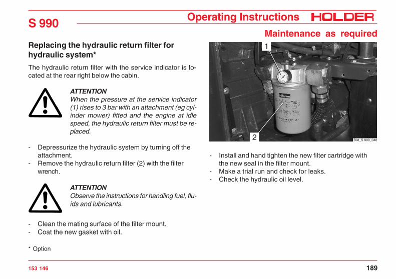
Operating Instructions
153 146 189
S 990Maintenance as required
Replacing the hydraulic return filter forhydraulic system*
The hydraulic return filter with the service indicator is lo-cated at the rear right below the cabin.
ATTENTIONWhen the pressure at the service indicator(1) rises to 3 bar with an attachment (eg cyl-inder mower) fitted and the engine at idlespeed, the hydraulic return filter must be re-placed.
- Depressurize the hydraulic system by turning off theattachment.
- Remove the hydraulic return filter (2) with the filterwrench.
ATTENTIONObserve the instructions for handling fuel, flu-ids and lubricants.
- Clean the mating surface of the filter mount.- Coat the new gasket with oil.
- Install and hand tighten the new filter cartridge withthe new seal in the filter mount.
- Make a trial run and check for leaks.- Check the hydraulic oil level.
* Option
Bild_S 990_046
1
2

S 990Operating Instructions
190 153 146
Maintenance as requiredATTENTIONCarry out the services and inspections onlywith the engine turned off.
Checking the radiator, cleaning if necessary
- Inspect the cooling fins and oil cooler for the accumu-lation of dirt.
Cleaning with compressed air
- Raise the platform* and secure it against accidentallowering.
- Blow out any dirt from the engine compartment to theoutside.
Cleaning with cold cleaner or water jet
ATTENTIONMaximum spray pressure 60 bar, maximumsteam temperature 60 °C
- Raise the dumping subframe (dump body*) andsecure it against accidental lowering.
- Spray the oil cooler and engine with a cold cleanerand allow it to soak in for 10 minutes.
- Clean the oil cooler and engine with a strong water jet.
ATTENTIONDo not aim the water jet directly at sensitiveparts such as the alternator, covering them ifnecessary.
- Run the engine warm to prevent the formation of rust.
Bild_C992H_063

Operating Instructions
153 146 191
S 990Maintenance as required
Cleaning the condenser
- Turn on the ignition (engine off).- Operate the fan reversal switch (1).- The fans will rotate in the reverse direction and run as
long as the switch is pushed.
NOTEWith this function it is easy to remove any collec-ted grass from the air conditioner.
Checking the condenser for the free flow ofair, cleaning if necessary
- Inspect the ribs for accumulation of dirt.- If little dirt has accumulated, blow out the ribs with
compressed air opposite to the normal direction of airflow.
- In case of a heavy accumulation of dirt or a greasycoating, first clean with a soap solution or an appro-priate cleaning solution (not aggressive for copper oraluminium) and followed by cleaning with compressedair or a jet of water.
1
Bild_C992H_064
2
3

S 990Operating Instructions
192 153 146
Maintenance as requiredCleaning the fresh air filter and filter mat,replacing if necessary
- Remove the fastening screws (1).- Remove the filter cover (2) and take out the filter
element.- Clean the filter element or replace it.
NOTEAn activated carbon filter* is available for usewith spray chemicals, etc.
- Refit the filter element and filter cover.- Remove the fastening screws (3).- Remove the panel (4).- If an air conditioner is installed, pull off the sealing
tape and remove the capillary tube (6) from theevaporator.
- Remove the filter (5).- Clean the filter mat or replace it with a new one.
Installation is in the reverse order of removal.
* Option
Bild_S 990_039
1 2 3 4

Operating Instructions
153 146 193
S 990Maintenance as required
Greasing the tractor (except universal joints)
- Grease all moving parts lightly.- Lubricate the grease nipples (1 and 2) according to the lubrication chart. Only use recommended grease.
ATTENTIONDo not press too much greaseinto grease nipple (2) as thiscould damage the sealing.

S 990Operating Instructions
194 153 146
Maintenance as requiredChecking the frost protection of thewindshield washer water
- Remove the filler cap (1) from the windshield washerfluid reservoir (2).
- Add a mixture of antifreeze and clear water.
NOTEThe percentage of antifreeze depends on the frostprotection used and the temperature to be expec-ted.
- Refit the filler cap (1). Bild_C992H_019
21

Operating Instructions
153 146 195
S 990
Maintenance every 250 service hours
Checking the engine for leaks
- Refer to page 169 of maintenance after the first 50service hours.
Checking the engine oil level
- Refer to page 46.
Checking the air tubes and air hoses forleaks
- Refer to page 169 of maintenance after the first 50service hours.
Checking the heating hoses for damage andtightness
- Refer to page 171 of maintenance after the first 50service hours.
Checking the radiator, cleaning if necessary
- Refer to page 190 of maintenance as required.

S 990Operating Instructions
196 153 146
Maintenance every 250 service hoursChecking the coolant, adding if necessary
- Remove the cap (1) of the coolant expansion reservoir.- Take a sample of the coolant and check its concen-
tration according to the engine operating instructions.Add coolant if necessary.
Checking the coolant level, topping up ifnecessary
- Refer to page 170 of maintenance after the first 50service hours. Bild_C992H_080
1

Operating Instructions
153 146 197
S 990Maintenance every 250 service hours
Checking the V-belt for tension and condi-tion, tightening or replacing if necessary
Please also refer to the operating instructions of the enginemanufacturer.
CAUTIONAdjust V-belt tension only when the engine isshut off.
- Inspect V-belts for cracks and tears over their entirelength.
- Replace any damaged V-belts.- Using thumb pressure, check that belt deflection is
not over 10 - 15 mm.- To tighten the V-belt: Loosen the idler pulley mounting
screws and push the pulley outwards until the properV-belt tension is reached.
- Tighten the fastening screws of the idler pulleymounting.

S 990Operating Instructions
198 153 146
Maintenance every 250 service hoursChecking the fuel lines for condition andtightness
- Check the fuel lines in the engine compartment for leaks.
Checking the cable connections
- Check the cables and plugs for security and damage.
Checking the hydraulic lines and hoses fordamage and tightness
- Refer to page 172 of maintenance after the first 50service hours.
Checking the steering cylinder for leaks andmechanical damage
- Check the steering cylinder for leaks and mechanicaldamage.
- Have damaged or leaking parts replaced by yourservice centre.
Checking the hydraulic oil level
- Refer to page 48.
Checking the front and rear gearbox for leaks
- Check the front and rear gearboxes and axles for leaks.
Checking the front and rear gearbox oil level
- Refer to page 175 and 177 of maintenance after thefirst 50 service hours.
Checking the speed range selector for easeof shifting
- Check the slow/fast speed range selector for ease ofshifting, cleaning and greasing the mechanism ifnecessary.
Checking the brake fluid level
- Refer to page 50.
Checking the service brake
- Refer to page 179 of maintenance after the first 50service hours.
Checking the parking brake for proper op-eration
- Refer to page 179 of maintenance after the first 50service hours.

Operating Instructions
153 146 199
S 990Maintenance every 250 service hours
Checking the heating system for properoperation
- Refer to page 125.
Checking the air conditioner for properoperation
- Refer to the operating instructions for the air conditioner.
Checking the sight glass of the air condi-tioner for the formation of bubbles
- Refer to the operating instructions for the air conditio-ner.
- Check the air conditioner for proper operation.- Observe the sight glass (1) during operation. In case
of formation of bubbles, an air conditioning expertmust bleed the unit.
Bild_S 990_0411

S 990Operating Instructions
200 153 146
Maintenance every 250 service hoursChecking the condenser for the free flow ofair, cleaning if necessary
- Refer to page 191 of maintenance as required.
Checking the seat of the compressor
- Check the compressor (1) for security and damage.
Checking the V-belt of the compressor forproper tension and condition
- Check the V-belt (2) for tension and condition.
Checking the condensate water drain
- Check the drain (2) of the condensate water, cleaningthe drain hose if necessary.
Visual inspection of air conditioner for leaks
- Make a visual inspection of the air conditioner andhoses for leaks.
Checking the air conditioner hoses andwiring for damage
- Check all hoses, pipes and wiring of the air conditio-ner for damage or chafing.
Bild_C992H_08721
Bild_S 990_042
1
3 2

Operating Instructions
153 146 201
S 990Maintenance every 250 service hours
Cleaning the fresh air filter and filter mat inthe fan box, replacing if necessary
- Clean the fresh air filter (1) and filter mat (3) in the fanbox, replacing them if necessary.
Checking the electrical system for properoperation, check the lighting
- To check the electrical installation, turn on the lighting(refer to page 119).
Checking the preheating system
- To check the preheating system, start the engine(refer to page 54).
Lubricate the machine (except universaljoints)
- Refer to page 193 of maintenance as required.
Bild_S 990_042
1
3 2

S 990Operating Instructions
202 153 146
Maintenance every 250 service hoursChecking the accelerator for ease of move-ment, clean and grease if necessary
- Check the accelerator (1) for ease of movement,clean and grease the mechanical parts if necessary
Checking the windshield washer water level,topping up if necessary
- Check the level in the reservoir (2) and add water, ifnecessary.
Checking the frost protection of thewindshield washer water
- Refer to page 194 of maintenance as required.
Checking the windscreen wiper, renewing ifnecessary
- Check the wiper blades, renewing them if necessary.
Tighten the wheel nuts
- Refer to page 180 of maintenance after the first 50service hours.
2
1
Bild_C992H_089
Tightening nuts and bolts according to thetorque table
- Refer to page 180 of maintenance after the first 50service hours.
Checking the tire inflation pressure
- Refer to page 47.

Operating Instructions
153 146 203
S 990
Maintenance every 500 service hours
Changing the engine oil (at least once a year)
- Run the engine to operating temperature.- Park the tractor on a level surface and switch off the
engine.- Place a suitable catch pan under the engine.
CAUTIONDanger of scalding when draining hot engineoil.
- Unscrew the oil drain plug (1).- Allow the oil to drain completely.
ATTENTIONObserve the instructions for handling fuel, flu-ids and lubricants.
- Screw the oil drain plug in again with a new sealingring and tighten to a torque of 55 Nm.
- Fill new engine oil through the filler neck (2). Only userecommended engine oil.
Filling quantity with filter .................................... 10.5 L
- Let the engine idle for a short time.- After approx. 1 minute, check the oil level with the
dipstick (3). Bild_C992H_067
2
3
Bild_C992H_0681

S 990Operating Instructions
204 153 146
Maintenance every 500 service hoursChanging the engine oil filter
Refer the operating instructions of the engine manufacturer.
- Remove the left rear wheel and fender.- Drain the engine oil.- Unscrew the air filter cartridge (1) with a filter wrench.
ATTENTIONObserve the instructions for handling fuel, flu-ids and lubricants.
- Clean the mating surface of the filter mount.- Screw a new air filter cartridge with a new gasket in
the filter mount until the seal makes contact.- Tighten the air filter cartridge half a turn.- Top up with engine oil and check the oil level.- Install the fender and rear wheel.
Bild_C992H_058
1

Operating Instructions
153 146 205
S 990
Maintenance every 1000 servicehours
Checking the engine valve clearances
- Check the valve clearances of the engine with referenceto the operating instructions of the engine manufacturer.Special knowledge and special tools are required forthis service.Entrust your authorized dealer with this service.
Checking the glow plugs
- Refer the operating instructions of the engine manu-facturer.
Replacing the fuel filter element
- Replace the fuel filter element according to theoperating instructions of the engine manufacturer.
Cleaning the strainer in the fuel pump, re-placing if necessary
- Clean the strainer and, if necessary, replace it accordingto the procedure in the engine operating instructions.
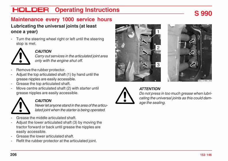
S 990Operating Instructions
206 153 146
Maintenance every 1000 service hoursLubricating the universal joints (at leastonce a year)
- Turn the steering wheel right or left until the steeringstop is met.
CAUTIONCarry out services in the articulated joint areaonly with the engine shut off.
- Remove the rubber protector.- Adjust the top articulated shaft (1) by hand until the
grease nipples are easily accessible.- Grease the top articulated shaft.- Move centre articulated shaft (2) with starter until
grease nipples are easily accessible.
CAUTIONNever let anyone stand in the area of the articu-lated joint when the starter is being operated.
- Grease the middle articulated shaft.- Adjust the lower articulated shaft (3) by moving the
tractor forward or back until grease the nipples areeasily accessible.
- Grease the lower articulated shaft.- Refit the rubber protector at the articulated joint.
ATTENTIONDo not press in too much grease when lubri-cating the universal joints as this could dam-age the sealing.
Bild_S 990_043
1
2
3

Operating Instructions
153 146 207
S 990
Maintenance every 1500 servicehours
Changing the hydraulic oil (at least every 2years)
- Refer to page 182 of maintenance after the first 500service hours.
Cleaning the suction filter of the traction andworking hydraulics, replacing if necessary(at least every 2 years)
- Refer to page 183 of maintenance after the first 500service hours.
Replacing the working hydraulics pressurefilter (at least every 2 years)
- Refer to page 173 of maintenance after the first 50service hours.
Replacing the traction hydraulics pressurefilter (at least every 2 years)
- Refer to page 174 of maintenance after the first 50service hours.
Changing the front and rear gearbox oil
- Refer to page 175 of maintenance after the first 50service hours.


Operating Instructions
153 146 209
S 990
Maintenance every 3000 servicehours
Changing the toothed belt
Change interval every 3000 service hours or every 5 yearsmaximum.Refer to the maintenance instructions of the engine manu-facturer.
ATTENTIONThis work may only be carried out by yourservice centre.
Replacing the injection nozzles
(Refer to the maintenance instructions of the engine manu-facturer)
ATTENTIONThis work may only be carried out by yourservice centre.


Operating Instructions
153 146 211
S 990
Annual maintenance
Changing the engine oil and oil filter car-tridge (every 500 hours minimum)
- Refer to page 203 of maintenance every 500 servicehours.
Changing the air filter element
- Refer to page 187 of maintenance as required.
Changing the brake fluid
ATTENTIONSpecial knowledge and special tools are re-quired for this service.Entrust your authorized dealer with this serv-ice.
Changing the fresh air filter
- Refer to page 192 of maintenance as required.

S 990Operating Instructions
212 153 146
Annual maintenanceChecking the battery, coating the terminalswith grease
CAUTIONObserve the following instructions for safetyreasons.The battery contains dissolved sulphuric acid,which is poisonous and caustic.When handling battery acid, wear personal pro-tective equipment (protective apron, protectivegloves) and eye protectors. If your clothing, skinor eyes have nevertheless come in contact withbattery acid, the affected parts must be rinsedat once with water. If the eyes are affected,seek medical aid immediately. Neutralize spilledbattery acid immediately.Gases are released when batteries are charged.To prevent an explosion, keep sparks and na-ked fires away. Rooms in which batteries arecharged or stored must be ventilated accord-ingly.
NOTEThe charging, servicing and care of the bat-tery must always be according to the main-tenance instructions of the battery manufac-turer.

Operating Instructions
153 146 213
S 990Annual maintenance
Bild_C992H_091
2
3
1Before doing work on the electrical equipment, cut off thepower with the battery isolating switch (3).
- The switch must be in the vertical position and thetoggle removed.
- Disconnect the battery ground lead (2).
- Disconnect the battery positive lead (1).
CAUTIONDo not place any metal parts on the batterypoles. Risk of short circuit!
- Coat the battery poles and battery terminals lightlywith pole grease.
- Charge the battery and top up the electrolyte withdistilled water.
Lubricating the universal joints
- Refer to page 206 of maintenance every 1000 servicehours.


Operating Instructions
153 146 215
S 990
Maintenance every 2 years
Changing the coolant
- Refer to the operating instructions of the enginemanufacturer.
- Fill coolant with reference to page 170.
Replacing the V-belt
- Replace the V-belt according to the operating instruc-tions of the engine manufacturer.
Checking the glow plugs
- Refer to the operating instructions of the engine.
Changing the hydraulic oil (or at 1500hours)
- Refer to page 182 of maintenance after the first 500service hours.
Replacing the suction filter of the tractionand working hydraulics (or at 1500 hours)
- Refer to page 183 of maintenance after the first 500service hours.
Replacing the working hydraulics pressurefilter (or at 1500 hours)
- Refer to page 173 of maintenance after the first 50service hours.
Replacing the traction hydraulics pressurefilter (or at 1500 hours)
- Refer to page 174 of maintenance after the first 50service hours.
Replacing the alternator and the water pumpV-belt
- Refer to the operating instructions of the enginemanufacturer.

S 990Operating Instructions
216 153 146
Maintenance every 2 yearsReplacing the air conditioner V-belt
- Remove the rear frame, radiator and annular fan.- Loosen the screws (3).- Loosen the locknut (2) and tensioning screw (1).- Remove the V-belt (4) and install a new V-belt.- Screw in the tensioning screw (1) until the correct belt
tension is reached.- Retighten the locknut (2) and screws (3).- Refit the annular fan.
ATTENTIONSecure the annular fan screws with Loctite243.
- Refit the rear frame and radiator.
Bild_S 990_044
1 2
3
Bild_S 990_0453

Operating Instructions
153 146 217
S 990
Maintenance every 5 years
Changing the toothed belt (or at 3000 hours)
- Refer to page 209 of maintenance every 3000 servicehours.

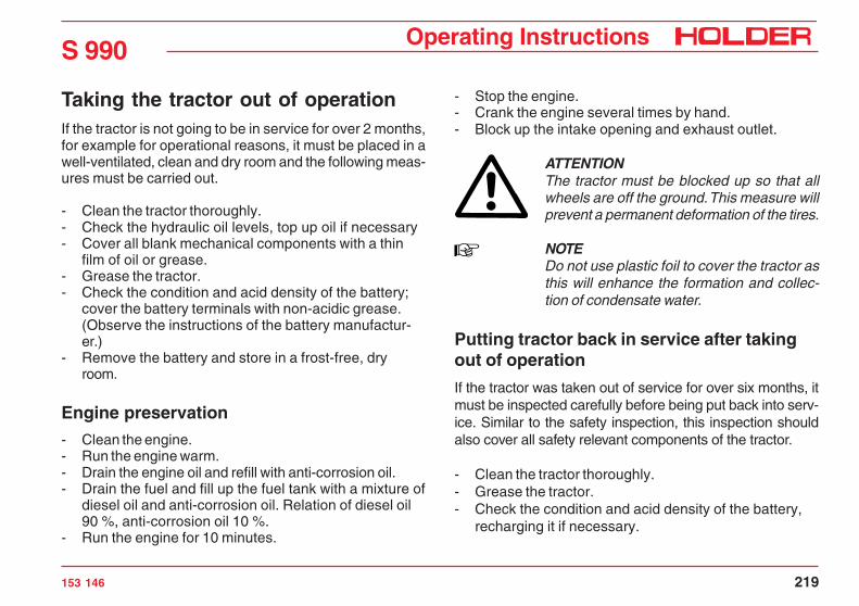
Operating Instructions
153 146 219
S 990
Taking the tractor out of operationIf the tractor is not going to be in service for over 2 months,for example for operational reasons, it must be placed in awell-ventilated, clean and dry room and the following meas-ures must be carried out.
- Clean the tractor thoroughly.- Check the hydraulic oil levels, top up oil if necessary- Cover all blank mechanical components with a thin
film of oil or grease.- Grease the tractor.- Check the condition and acid density of the battery;
cover the battery terminals with non-acidic grease.(Observe the instructions of the battery manufactur-er.)
- Remove the battery and store in a frost-free, dryroom.
Engine preservation
- Clean the engine.- Run the engine warm.- Drain the engine oil and refill with anti-corrosion oil.- Drain the fuel and fill up the fuel tank with a mixture of
diesel oil and anti-corrosion oil. Relation of diesel oil90 %, anti-corrosion oil 10 %.
- Run the engine for 10 minutes.
- Stop the engine.- Crank the engine several times by hand.- Block up the intake opening and exhaust outlet.
ATTENTIONThe tractor must be blocked up so that allwheels are off the ground. This measure willprevent a permanent deformation of the tires.
NOTEDo not use plastic foil to cover the tractor asthis will enhance the formation and collec-tion of condensate water.
Putting tractor back in service after takingout of operation
If the tractor was taken out of service for over six months, itmust be inspected carefully before being put back into serv-ice. Similar to the safety inspection, this inspection shouldalso cover all safety relevant components of the tractor.
- Clean the tractor thoroughly.- Grease the tractor.- Check the condition and acid density of the battery,
recharging it if necessary.

S 990Operating Instructions
220 153 146
Taking the tractor out of operationRemoving the engine preservation
- Unblock the intake opening and exhaust outlet.- Drain the anti-corrosion oil and rinse the oil sump with
engine oil.
ATTENTIONObserve the instructions for handling fuel, flu-ids and lubricants.
See the section „Changing the engine oil“ on how to pro-ceed further.
- Check the hydraulic oil for condensation water,change the oil if necessary.
- Perform the services and inspections as for beforetaking into service.
- Fill the fuel tank.- Renew the brake fluid.- Take the tractor into operation.
When taking into the tractor into service, particularly check:
- Gearboxes and axles for leaks.- Traction hydraulics, gearshift, steering.- Brakes (service brake, parking brake)- Working hydraulics, functions and work movements.
If the tractor is to be laid up for a longer period, pleasecontact your HOLDER Service for further measures.

Operating Instructions
153 146 221
S 990
Coolant, fuel and lubricant specificationsUse Fluids and lubricants Specification Season
Engine(Refer to Deutz operating instructions)
Multi-purpose engine oil
SAE 5W-40 All-season
ACEA E3-96/E5-02;E4-99/E6-04
API CH-4/CG-4; DHD-1
Hydraulic oil tank (traction and working hydraulics)
Hydraulic oil HE oils (hydraulic ester) VG 46 All-season
Mineral hydraulic oil HLPto DIN 51524
VG 46 Winter
VG 68 Summer
Fuel tank(Refer to Deutz operating instructions)
Diesel fuel Commercial diesel fuels with asulphur content under 0.5 %
DIN EN 590
All-season
Brake system Brake fluid DOT 4 All-season
Air conditioner Refrigerant R 134 a All-season
Hydrostatic transmission UTTO special oil SAE 10W-30 All-season(front) API GL4
Transmission UTTO special oil SAE 10W-30 All-season(rear) API GL4
Grease nipples Multipurpose grease Penetration numberfrom 260 to 290
All-season


Operating Instructions
153 146 223
S 990
S 990
Engine oilIncl. filter 0.5 litre
8.5 litres
Cooling system with heater approx. 13 litres
Hydraulic oil tank for working and traction hydraulics, hydraulic oil*Initial filling (depending on equipment)
approx. 45-50 litresapprox. 50-55 litres
Front hydrostatic transmission with axles, gear oilInitial filling
10.9 litres12.7 litres
Rear transmission with axles, gear oil 17.75 litresReduction gearbox 0.2 litre SAE 80
Brake fluid for hydr. footbrake 0.4 litre
Fuel tank, diesel fuel 82 litres
Windshield washer fluid reservoir approx. 2.5 litres
Maintenance data
Filling quantities
* NOTEIn order to ensure the biological degradabilityof the hydraulic oil, all attachments connectedto the tractor hydraulic system must also beoperated with HE oil.
Residual quantities of mineral oils reduce thebiological degradability, but they do not influ-ence operation.

S 990Operating Instructions
224 153 146
Maintenance dataTightening torques
Hexagon head and set screws M8 M10 M12 M14 M16Screw grade 8.8 25 Nm 49 Nm 86 Nm 135 Nm 210 NmScrew grade 10.9 35 Nm 69 Nm 120 Nm 190 Nm 295 Nm
Transmission, axles, wheels Torque
M10 hex head screws(orbitrol to steering column)
40 Nm
Clamping screws for hydraulic controlvalves
16 Nm
Axle spindle to transmission case 86 Nm
Axle spindle cover M10 (planetary gear) 69 Nm
Spherical bearing M12 86 Nm
Lock bar M16 210 Nm
Coupling jaw attachment bar M14 135 Nm
Wheel fastener (incl. hub spacer) 340 Nm
Engine Torque
Cylinder head cover 8.5 Nm
Rocker arm adjustment screw 21 Nm
Intake manifold 8.5 Nm
Air intake pipe (TORX) 21 Nm
Exhaust manifold (TORX) 22 Nm
Oil drain plug 55 Nm
Oil sump (cast) 31 Nm
Injection line fastener 30 Nm
Injection valve fastener (TORX) 21 Nm
Plugs and connecting screws for heatinghoses 65 + 5 Nm

Operating Instructions
153 146 225
S 990Maintenance data
List of replacement parts
Designation Order number
Sealing ring for oil drain plug 010 395Engine oil filter 797 135Fuel filter 782 971Cylinder head cover gasket 798 097Air filter element 029 760V-belt for KHD fan 798 095 (10x1250)Toothed belt repair kit 797 499Hydraulic suction filter (working and traction hydraulics) 029 541 (2 items)O-ring 64X3 014 696 (2 items)Hydraulic pressure filter (working and traction hydraulics) 132 897 (2 items)O-ring 63.17X2.62 for hydraulic pressure filter 028 109 (2 items)Replacement cartridge for power hydraulic system return filter 029 088Replacement cartridge for attachment variable pump return filter 143 991Filter element (cabin fresh air filter) 131 666Ventilation filter with activated charcoal (cabin fresh air filter) 131 667Spray paint can, black grey RAL 7021 029 000Spray paint can, orange RAL 2004 020 656Spray paint can, silver RAL 9006 031 053

S 990Operating Instructions
226 153 146
Maintenance dataBulbs 12 V
Use Power Use Rating
Low beam headlight H7 55 W Front top working light H7 55 WHigh beam headlight H7 55 W Rear working light H3 55 WFront turn signal light 21 W Indicator lights in switches 1.2 WRear turn signal light 21 W Yellow indicator light 2 WTail light 10 W Position lights 5 WLicence plate light 5 W Dome light 5 WBrake light 21 W Top strobe warning light H1 55 WBack-up light 21 W Multifunctional display
incandescent lampsDIN 72601/W5/12 V
1.2 / 3.0 W

Operating Instructions
153 146 227
S 990Maintenance data
Technical data of the engine
S 990Manufacturer Deutz AGModel designation TD2011 L04w EU Tier IIIADesign Vertical in-lineType 4-stroke dieselCooling Water coolingMethod of injection Direct fuel injectionNo. of cylinders 4Cylinder bore Ø 96Stroke 125Cubic capacity 3619 cm³Compression ratio 1:18Max . charge pressure 1.4 barValve clearances when cold Intake valve 0.3 mm
Exhaust valve 0.5 mmSpecific fuel consumption 216 g/kWhAir filter Mann & Hummel dry filter with acoustic warning systemLubricating system Forced-feed lubricationLubricating oil consumption 0.5% maximum of fuel consumptionOil filter replacement cartridge in the main streamOil pressure at n=2600 RPM 1.5 barRated speed 2600 RPMUpper idle speed 2600 RPM +200 RPMLower idle speed 900-950 RPMMax. torque to 97/68 EC 280 Nm at 1600 RPMPower to 97/68 ECat n=2600 RPM 68.0 kW (92 HP)

S 990Operating Instructions
228 153 146
Maintenance dataFuel system
S 990
Injection pump Motorpal single plug-in pumpGovernor Governor integrated in the front coverInjection nozzle/openingpressure
Multi-hole nozzle/180 bar + 10 bar
Start of injection 2°+/-0.5° after TDC
Traction pump Hydrostatic driveAxial piston pump, type 11 VG50 EPRated pressure 300 barMaximum pressure 350 barA4 VG40 EPRated pressure 380 barMaximum pressure 430 bar
Traction motor Axial piston motor / type AG KM 55

Operating Instructions
153 146 229
S 990
Page Page
Alphabetical index
A
Accessories ..................................................................43Activating the left / right turn signal ............................. 121Additional information for attachments ..........................80Adjusting control sensitivity (hysteresis) ..................... 103Adjusting the backrest tilt .............................................51Adjusting the catch hooks .............................................84Adjusting the driver’s seat with pneumatic suspension ..51Adjusting the driver’s weight ..........................................52Adjusting the fine adjustment knob ...............................65Adjusting the hitch insert length ....................................84Adjusting the horizontal suspension ..............................52Adjusting the lumbar support ........................................51Adjusting the speedometer ................................. 143, 185Adjusting the steering wheel .........................................50Adjusting the tilt with membrane keyboard ....................92Adjusting the track width ...............................................76Adjusting the upper link slide and upper link ..................85Air conditioning ........................................................... 128Annual maintenance.................................................... 211Applications with hydraulic accumulator ...................... 104Applying the parking brake ............................................72
B
Ballasting ......................................................................78Battery ..........................................................................14Battery acid ..................................................................13Before starting to drive..................................................59Brakes ..........................................................................72Bulbs 12 V .................................................................. 226
C
Changing the air filter element ..................................... 211Changing the brake fluid .............................................. 211Changing the coolant .................................................. 215Changing the direction of travel .....................................67Changing the engine oil (at least once a year) ............. 203Changing the engine oil and oil filter cartridge
(every 500 hours minimum) .................................. 211Changing the engine oil filter ....................................... 204Changing the fresh air filter ......................................... 211Changing the front and rear gearbox oil .............. 175, 207Changing the front gearbox oil (including axle) ............ 175Changing the gear oil of the rear gearbox
(including offset axles) ......................................... 177
S 990Operating Instructions
230 153 146
Alphabetical indexPage Page
Changing the hydraulic oil (at least every 2 years) ...... 207Changing the hydraulic oil (or at 1500 hours) ............... 215Changing the toothed belt ........................................... 209Changing the toothed belt (or at 3000 hours) ............... 217Check the service brake ............................................. 179Checking air tubes and air hoses for leaks .................. 169Checking engine V-belt tension and condition .............. 171Checking the accelerator for ease of movement,
clean and grease if necessary ............................. 202Checking the air cleaner system,
cleaning if necessary ........................................... 187Checking the air conditioner for proper operation ......... 199Checking the air conditioner hoses and wiring
for damage ........................................................... 200Checking the air tubes and air hoses for leaks ............ 195Checking the battery, coating the terminals
with grease .......................................................... 212Checking the brake fluid level .............................. 50, 198Checking the brakes and steering for proper function ....57Checking the cable connections .................................. 198Checking the condensate water drain .......................... 200Checking the condenser for the free flow of air,
cleaning if necessary .................................. 191, 200
Checking the coolant, adding if necessary .................. 196Checking the coolant level,
topping up if necessary ............................... 170, 196Checking the electrical system for proper operation,
check the lighting ................................................. 201Checking the engine for leaks ............................ 169, 195Checking the engine oil level ................................ 46, 195Checking the engine valve clearances ............... 184, 205Checking the front and rear gearbox for leaks ............. 198Checking the front and rear gearbox oil level ............... 198Checking the frost protection of the windshield
washer water ............................................... 194, 202Checking the fuel lines for condition and tightness ...... 198Checking the glow plugs .................................... 205, 215Checking the heating hoses for damage
and tightness .............................................. 171, 195Checking the heating system for proper operation ....... 199Checking the hydraulic lines and hoses for damage
and tightness ....................................................... 198Checking the hydraulic lines and hoses for leaks
and damage ......................................................... 172Checking the hydraulic oil level ................... 48, 172, 198Checking the lights and rear view mirror ........................53

153 146 231
S 990Alphabetical index
Operating Instructions
Page Page
Checking the parking brake for proper operation . 179, 198Checking the preheating system ................................. 201Checking the radiator, cleaning if necessary ...... 190, 195Checking the seat of the compressor .......................... 200Checking the service brake ......................................... 198Checking the sight glass of the air conditioner
for the formation of bubbles ................................. 199Checking the speed range selector for ease of shifting .. 198Checking the steering cylinder for leaks
and mechanical damage ...................................... 198Checking the tire inflation pressure ...................... 47, 202Checking the trailer coupling (optional) if necessary ......47Checking the V-belt for tension and condition,
tightening or replacing if necessary ...................... 197Checking the V-belt of the compressor for proper
tension and condition ........................................... 200Checking the windscreen wiper, renewing if necessary .. 202Checking the windshield washer water level,
topping up if necessary ........................................ 202Checking/cleaning the radiator and protection screens ..45Cleaning the condenser ...................................... 128, 191Cleaning the fresh air filter and filter mat in the fan box,
replacing if necessary .......................................... 201
Cleaning the fresh air filter and filter mat,replacing if necessary .......................................... 192
Cleaning the strainer in the fuel pump,replacing if necessary ................................. 171, 205
Cleaning the suction filter of the traction and workinghydraulics, replacing if necessary(at least every 2 years) ........................................ 207
Cleaning the suction filters of the traction and workinghydraulics, replacing if necessary ........................ 183
Cleaning with cold cleaner or water jet ........................ 190Cleaning with compressed air ...................................... 190Connecting equipment to the power socket ................. 124Connecting line for priority flow valves 1 and 2 ............ 115Continual development ................................................... 1Controls at front bottom of cabin ...................................36Controls at front top of cabin .........................................36Controls at rear of cabin ................................................37Controls on rear console ...............................................32Controls on right front console .......................................30Controls on right rear console ........................................31Coolant, fuel and lubricant specifications .................... 221Coupling the hydraulic hoses ........................................86

S 990Operating Instructions
232 153 146
Alphabetical indexPage Page
D
Daily checks and activities prior to taking into service ..45Date of issue and version of instructions ....................... 2Description ....................................................................27Determination of the total weight, axle loads and
tire load capacity including minimum ballasting ......80Dimensional drawing .....................................................15Disposal instructions ...................................................... 6Distance between centreline of tires ..............................17Doing work on the electrical equipment ....................... 158Dome light ................................................................... 123Door controls .................................................................37Driver’s licence ............................................................... 7Driver’s licence classes ................................................. 7Driver’s station ..............................................................29Driving ..........................................................................60Driving on slopes ..........................................................74Driving with a trailer ..................................................... 137Driving with hydrostatic drive ........................................60Driving with hydrostatic DUAL drive ..............................68Driving with SDS (Special Drive System) ......................66
E
Emissions .....................................................................13
Engine and exhaust gas turbocharger malfunctions .... 145Engine instructions before operation .............................54Engine oil for winter operation .......................................78Engine preservation .................................................... 219Engine specifications ....................................................20Exhaust gas identification .............................................26Exhaust Gases .............................................................13Explanation of the cautions used ................................... 2External operation of the front lift ..................................94External operation of the rear lift ...................................97
F
Filling fuel .....................................................................49Filling oil ..................................................................... 176Flow rate limiting for joystick .........................................95Foreword ........................................................................ 1Front left view ...............................................................27Front lift tilt control ........................................................90Front windshield wiper/washer ..................................... 118Fuel system ................................................................ 228Fuse for automatic preheating ..................................... 131Fuses ......................................................................... 129Fuses for the tractor .................................................... 129

153 146 233
S 990Alphabetical index
Operating Instructions
Page Page
G
Gear oil, engine oil, diesel fuel ......................................12General notes on safety ................................................11General notes on service ............................................... 1General remarks on maintenance ................................ 155Greasing the tractor (except universal joints) .............. 193
H
Hand throttle .................................................................32Handling fuel, fluids and lubricants .............................. 156Heat ..............................................................................14Heater ......................................................................... 125Heating and ventilating ................................................ 125Hoisting instructions .................................................... 139Horizontal seat adjustment ............................................52How to value the tractor? ............................................ 155Hydraulic and steering system malfunctions ............... 149Hydraulic oil, brake fluid ................................................13Hydraulic oil for stationary operation .............................75Hydraulic system ..........................................................78
I
Identification plates .......................................................38Indication of special operating conditions .................... 143
Indicators, adjustments ............................................... 143Information on the tractor ............................................... 5Installation of attachments ............................................83Installing the articulated shafts .....................................87Intended use .................................................................. 5
J
Jack lift points ............................................................ 159Jacking up .................................................................. 159Joystick ........................................................................33Joystick operation .........................................................89
L
Lateral control of the front lift ........................................90Lateral control with the membrane keyboard .................93Leaving the tractor unattended ........................... 133, 134Lights .......................................................................... 119List of replacement parts ............................................ 225Location of plates and labels .........................................38Lubricate the machine (except universal joints) ........... 201Lubricating the universal joints .................................... 213Lubricating the universal joints (at least once a year) .. 206

S 990Operating Instructions
234 153 146
Alphabetical indexPage Page
M
Maintenance after the first 50 service hours ................ 169Maintenance after the first 500 service hours .............. 181Maintenance as required ............................................. 185Maintenance data........................................................ 223Maintenance during the initial period of operation ...163, 169Maintenance every 1000 service hours ....................... 205Maintenance every 1500 service hours ....................... 207Maintenance every 2 years ......................................... 215Maintenance every 250 service hours ......................... 195Maintenance every 3000 service hours ....................... 209Maintenance every 5 years ......................................... 217Maintenance every 500 service hours ......................... 203Maintenance schedule ................................................ 163Malfunctions, causes, remedy .................................... 145Mounting instructions for licence plate ..........................39Multifunctional display ...................................................35Multiple-axle trailers and two-axle trailers with ................ 9
N
Noise level ....................................................................26
O
Oil preheating ................................................................78
Opening the roof hatch ................................................ 117Operating controls .........................................................29Operating instructions .................................................... 7Operating priority flow valve I ...................................... 111Operating priority flow valve II ..................................... 113Operating the 4-way hazard flashers ........................... 122Operating the air conditioning ...................................... 128Operating the attachment variable pump
(adjustable to 0-120 L) ......................................... 105Operating the attachments ............................................79Operating the blue hydraulic couplings ..........................99Operating the driver’s cabin ......................................... 117Operating the emergency gear release
(hydrostatic DUAL drive only) .................................77Operating the front lift ...................................................90Operating the front lift with the membrane keyboard ......91Operating the green hydraulic couplings ........................99Operating the horn ...................................................... 121Operating the hydraulic accumulator (front lift) ............ 103Operating the hydraulic couplings .................................98Operating the hydraulic dumping device ...................... 110Operating the hydraulic system (fixed setting 80 L) ..... 108Operating the inching pedal ...........................................67

153 146 235
S 990Alphabetical index
Operating Instructions
Page Page
Operating the joystick ...................................................88Operating the radio ...................................................... 124Operating the rear lift ....................................................96Operating the roof hatch .............................................. 117Operating the service brake ..........................................72Operating the trailer coupling, attaching trailers ........... 136Operating the windshield wiper/washer ........................ 118Operating the yellow and white hydraulic couplings .......99Operation ......................................................................59Operation in winter ........................................................78Other operations ......................................................... 117Overview of options and variants (selection) .................40
P
Parking ........................................................................ 134Parking the tractor ....................................................... 133Pedals ...........................................................................33Periodic maintenance ........................ 165, 166, 167, 168Possible attachments ....................................................79Power socket .............................................................. 124Putting on snow chains .................................................78Putting tractor back in service after taking
out of operation .................................................... 219
Q
Qualification of service personnel ............................... 155
R
Radio and loudspeaker ................................................ 124Rear attachment or front/rear combinations ...................81Rear right view ..............................................................28Recirculating air operation ........................................... 127Regular maintenance .................................................. 164Releasing the parking brake ..........................................73Removing attachments .................................................87Removing the engine preservation .............................. 220Removing the roof hatch ............................................. 117Replacing the air conditioner V-belt .............................. 216Replacing the alternator and the water pump V-belt ..... 215Replacing the fuel filter element .................................. 205Replacing the hydraulic oil of the traction and working
hydraulic system ................................................. 182Replacing the hydraulic return filter for
hydraulic system ................................................. 189Replacing the hydraulic return filter for the
attachment variable pump .................................... 188Replacing the injection nozzles ................................... 209

S 990Operating Instructions
236 153 146
Alphabetical indexPage Page
Replacing the suction filter of the traction andworking hydraulics (or at 1500 hours) ................... 215
Replacing the traction hydraulicspressure filter ............................. 174, 181, 207, 215
Replacing the V-belt .................................................... 215Replacing the working hydraulics pressure filter . 173, 181Replacing the working hydraulics pressure filter
(at least every 2 years) ............................... 207, 215Residual hazards and risks ............................................ 6
S
Safety ...........................................................................11Safety instructions for handling attachments.................79Safety instructions for handling fuel, fluids
and lubricants ........................................................12Safety notes for maintenance ..................................... 156Safety notes for retrofits ...............................................11Securing the dumping subframe (dump body) ............. 160Selecting road travel (transport speed) ..........................63Service ....................................................................... 155Setting key for float position button ...............................95Setting the operating speed of programs 3 and 4 ..........63
Single-axle trailers or two-axle trailers with axle baseof up to 1 metre maximum ...................................... 8
Site of operation ............................................................. 5Special operating instructions .......................................75Starting instructions ......................................................54Starting procedure ........................................................57Starting the engine ................................................. 54, 55Starting the engine with automatic preheating ...............57Stationary operation ......................................................75Steering ........................................................................71Steering column adjustment ..........................................34Stopping the tractor ..................................................... 133Switching off the attachment variable pump ................ 107Switching off the hydraulic system.............................. 109Switching the differential lock off ...................................70Switching the differential lock on ...................................70Switching the front lift to double-acting ..........................92Switching the hydraulic accumulator off ...................... 104
T
Table of contents ............................................................ 3Table of dimensions for S 990 .......................................16Table of driving programs ..............................................62

153 146 237
S 990Alphabetical index
Operating Instructions
Page Page
Table of ground speed ranges........................................61Table of ground speed ranges with DUAL Drive .............68Table of noise levels and absorption rating ....................26Table of trailers ............................................................ 135Taking into service ........................................................45Taking the tractor out of operation ............................... 219Technical data ...............................................................15Technical data /filling quantities .....................................22Technical data of the engine ........................................ 227Theoretical ground speeds ............................................21Tighten the wheel nuts ................................................ 202Tightening nuts and bolts according to
the torque table ........................................... 180, 202Tightening the wheel nuts ........................................... 180Tightening torques ...................................................... 224Tilting the cabin .......................................................... 161Tires .............................................................................19Tongue weight ............................................................. 136Topping up wiper water ..................................................53Towing instructions ...................................................... 140Traction electronics and traction hydraulics
malfunctions ........................................................ 145Tractor ...........................................................................28
Tractor dimensions ........................................................15Tractors for farming and forestry (also with attachments) .. 7Trailers, towing ............................................................ 135Transport, hoisting, towing .......................................... 139Transport instructions .................................................. 139Transport safety ............................................................93Turning off the priority flow valve ........................ 112, 114Turning on and operating the lights .............................. 119Turning on high beam .................................................. 119Turning on the battery isolating switch ...........................46Turning on the dome light ............................................ 123Turning on the front PTO ............................................. 100Turning on the heating ................................................. 125Turning on the rear PTO .............................................. 102Turning on the top headlights ....................................... 121Turning on the top strobe warning light ........................ 122Turning on the ventilation ............................................. 126Turning on the working lights ....................................... 123Two trailers behind tractors for farming and forestry ......10Two-stage steering ........................................................71
U
Unintended use .............................................................. 5

S 990Operating Instructions
238 153 146
Alphabetical indexPage
V
Views of vehicle ............................................................27Visual inspection of air conditioner for leaks ............... 200
W
Weights.........................................................................18Winter diesel fuel ..........................................................78Working clothes ............................................................11Working hydraulics malfunctions ................................. 151