990-3611 tdm.book - Octopart
40
Technical Data SKU ACDA901 Refrigerant Distribution Unit (RDU) and Piping
-
Upload
khangminh22 -
Category
Documents
-
view
1 -
download
0
Transcript of 990-3611 tdm.book - Octopart
Technical Data
SKUACDA901
Refrigerant Distribution Unit(RDU) and Piping

American Power Conversion Legal DisclaimerThe information presented in this manual is not warranted by the American Power Conversion Corporation to be authoritative, error free, or complete. This publication is not meant to be a substitute for a detailed operational and site specific development plan. Therefore, American Power Conversion Corporation assumes no liability for damages, violations of codes, improper installation, system failures, or any other problems that could arise based on the use of this Publication.
The information contained in this Publication is provided as is and has been prepared solely for the purpose of evaluating data center design and construction. This Publication has been compiled in good faith by American Power Conversion Corporation. However, no representation is made or warranty given, either express or implied, as to the completeness or accuracy of the information this Publication contains.
IN NO EVENT SHALL AMERICAN POWER CONVERSION CORPORATION BE LIABLE FOR ANY DIRECT, INDIRECT, CONSEQUENTIAL, PUNITIVE, SPECIAL, OR INCIDENTAL DAMAGES (INCLUDING, WITHOUT LIMITATION, DAMAGES FOR LOSS OF BUSINESS, CONTRACT, REVENUE, DATA, INFORMATION, OR BUSINESS INTERRUPTION) RESULTING FROM, ARISING OUT, OR IN CONNECTION WITH THE USE OF, OR INABILITY TO USE THIS PUBLICATION OR THE CONTENT, EVEN IF AMERICAN POWER CONVERSION CORPORATION HAS BEEN EXPRESSLY ADVISED OF THE POSSIBILITY OF SUCH DAMAGES. AMERICAN POWER CONVERSION CORPORATION RESERVES THE RIGHT TO MAKE CHANGES OR UPDATES WITH RESPECT TO OR IN THE CONTENT OF THE PUBLICATION OR THE FORMAT THEREOF AT ANY TIME WITHOUT NOTICE.
Copyright, intellectual, and all other proprietary rights in the content (including but not limited to software, audio, video, text, and photographs) rests with American Power Conversion Corporation or its licensors. All rights in the content not expressly granted herein are reserved. No rights of any kind are licensed or assigned or shall otherwise pass to persons accessing this information.
This Publication shall not be for resale in whole or in part.
Contents
Overview .......................................................................... 1
Scalable Solution for Critical Environments ................ 2Refrigerant . . . . . . . . . . . . . . . . . . . . . . . . . . . . . . . . . . . . . . . . . . . . . . 2High Density . . . . . . . . . . . . . . . . . . . . . . . . . . . . . . . . . . . . . . . . . . . . 2Leased Facilities . . . . . . . . . . . . . . . . . . . . . . . . . . . . . . . . . . . . . . . . . 2APC Pumped Refrigerant System, The Right Solution . . . . . . . . . . 2InRow Advantages . . . . . . . . . . . . . . . . . . . . . . . . . . . . . . . . . . . . . . . 2Scalable for High Density . . . . . . . . . . . . . . . . . . . . . . . . . . . . . . . . . 3
Standard Features........................................................... 4Cabinet . . . . . . . . . . . . . . . . . . . . . . . . . . . . . . . . . . . . . . . . . . . . . . . . . 4Heat Exchanger . . . . . . . . . . . . . . . . . . . . . . . . . . . . . . . . . . . . . . . . . . 4Redundant Refrigerant Pumps . . . . . . . . . . . . . . . . . . . . . . . . . . . . . 4Microprocessor Control . . . . . . . . . . . . . . . . . . . . . . . . . . . . . . . . . . . 42-way/3-way Water Control Valves . . . . . . . . . . . . . . . . . . . . . . . . . . 4Top or Bottom Power Feed . . . . . . . . . . . . . . . . . . . . . . . . . . . . . . . . 4Shutdown Input/Alarm Output . . . . . . . . . . . . . . . . . . . . . . . . . . . . . . 4Selectable Top or Bottom Piping Connections . . . . . . . . . . . . . . . . 4Network Management Card . . . . . . . . . . . . . . . . . . . . . . . . . . . . . . . . 4Bay Kit-NetShelter SX . . . . . . . . . . . . . . . . . . . . . . . . . . . . . . . . . . . . 4Insulation Kit . . . . . . . . . . . . . . . . . . . . . . . . . . . . . . . . . . . . . . . . . . . . 4
Optional Features............................................................ 5Flange Kit . . . . . . . . . . . . . . . . . . . . . . . . . . . . . . . . . . . . . . . . . . . . . . 5Rack Door Kit . . . . . . . . . . . . . . . . . . . . . . . . . . . . . . . . . . . . . . . . . . . 5Flexible Stainless Steel Hoses . . . . . . . . . . . . . . . . . . . . . . . . . . . . . 5Network Cable . . . . . . . . . . . . . . . . . . . . . . . . . . . . . . . . . . . . . . . . . . . 5Pipe Clamp Kit . . . . . . . . . . . . . . . . . . . . . . . . . . . . . . . . . . . . . . . . . . 51, 2, And 3-port RDU Piping Kits . . . . . . . . . . . . . . . . . . . . . . . . . . . . 5
Microprocessor Controller ............................................. 6Microprocessor Controller . . . . . . . . . . . . . . . . . . . . . . . . . . . . . . . . . 6Controls . . . . . . . . . . . . . . . . . . . . . . . . . . . . . . . . . . . . . . . . . . . . . . . . 6Alarms . . . . . . . . . . . . . . . . . . . . . . . . . . . . . . . . . . . . . . . . . . . . . . . . . 6Logging . . . . . . . . . . . . . . . . . . . . . . . . . . . . . . . . . . . . . . . . . . . . . . . . 7Display Interface . . . . . . . . . . . . . . . . . . . . . . . . . . . . . . . . . . . . . . . . . 7
RDU Technical Data Manual i
Component Identification ............................................... 8Insulation kit . . . . . . . . . . . . . . . . . . . . . . . . . . . . . . . . . . . . . . . . . . . 11
Optional kits . . . . . . . . . . . . . . . . . . . . . . . . . . . . . . . . . . . . . . . . . . . . 12Rack door kit - ACAC21005 . . . . . . . . . . . . . . . . . . . . . . . . . . . . . . . 12Flange kit - ACAC21006 . . . . . . . . . . . . . . . . . . . . . . . . . . . . . . . . . . 13Pipe clamp kit - ACAC11005 . . . . . . . . . . . . . . . . . . . . . . . . . . . . . . . 13RDU piping kit, one port - ACAC21000 . . . . . . . . . . . . . . . . . . . . . . 14RDU piping kit, two port - ACAC21002 . . . . . . . . . . . . . . . . . . . . . . 14RDU piping kit, three port - ACAC21004 . . . . . . . . . . . . . . . . . . . . . 15914 mm (3 ft) stainless steel flex pipe kit - ACAC21007 . . . . . . . . . 151828 mm (6 ft) stainless steel flex pipe kit - ACAC21008 . . . . . . . . 16
Performance Specifications ......................................... 17
General Data .................................................................. 18
Dimensional Data .......................................................... 21Service access dimensions . . . . . . . . . . . . . . . . . . . . . . . . . . . . . . . 21
Piping and Mechanical Connections........................... 22Internal Piping Diagram . . . . . . . . . . . . . . . . . . . . . . . . . . . . . . . . . . 22
External Piping Diagrams . . . . . . . . . . . . . . . . . . . . . . . . . . . . . . . . . 23OA units . . . . . . . . . . . . . . . . . . . . . . . . . . . . . . . . . . . . . . . . . . . . . . . 23RA units . . . . . . . . . . . . . . . . . . . . . . . . . . . . . . . . . . . . . . . . . . . . . . . 24
Piping and Power Access Locations........................... 26Top view . . . . . . . . . . . . . . . . . . . . . . . . . . . . . . . . . . . . . . . . . . . . . . . 26Bottom view (looking up) . . . . . . . . . . . . . . . . . . . . . . . . . . . . . . . . . 27
Guide Specifications..................................................... 28Guidelines for Installation . . . . . . . . . . . . . . . . . . . . . . . . . . . . . . . . . 33
Room preparation . . . . . . . . . . . . . . . . . . . . . . . . . . . . . . . . . . . . . . . 33Service access . . . . . . . . . . . . . . . . . . . . . . . . . . . . . . . . . . . . . . . . . . 33Receiving the unit . . . . . . . . . . . . . . . . . . . . . . . . . . . . . . . . . . . . . . . 33Rigging . . . . . . . . . . . . . . . . . . . . . . . . . . . . . . . . . . . . . . . . . . . . . . . . 33
RDU Technical Data Manualii
Overview
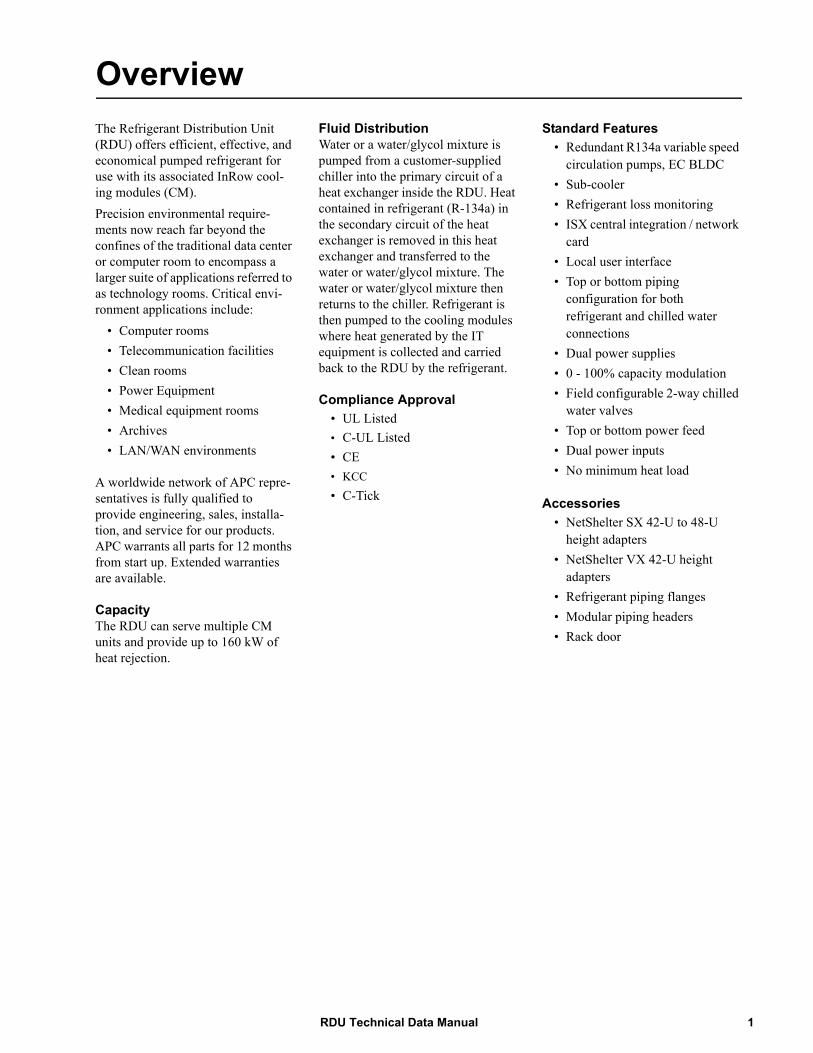
The Refrigerant Distribution Unit (RDU) offers efficient, effective, and economical pumped refrigerant for use with its associated InRow cool-ing modules (CM).Precision environmental require-ments now reach far beyond the confines of the traditional data center or computer room to encompass a larger suite of applications referred to as technology rooms. Critical envi-ronment applications include:• Computer rooms• Telecommunication facilities• Clean rooms• Power Equipment• Medical equipment rooms• Archives• LAN/WAN environments
A worldwide network of APC repre-sentatives is fully qualified to provide engineering, sales, installa-tion, and service for our products. APC warrants all parts for 12 months from start up. Extended warranties are available.
CapacityThe RDU can serve multiple CM units and provide up to 160 kW of heat rejection.
Fluid DistributionWater or a water/glycol mixture is pumped from a customer-supplied chiller into the primary circuit of a heat exchanger inside the RDU. Heat contained in refrigerant (R-134a) in the secondary circuit of the heat exchanger is removed in this heat exchanger and transferred to the water or water/glycol mixture. The water or water/glycol mixture then returns to the chiller. Refrigerant is then pumped to the cooling modules where heat generated by the IT equipment is collected and carried back to the RDU by the refrigerant.
Compliance Approval• UL Listed• C-UL Listed• CE• KCC• C-Tick
Standard Features• Redundant R134a variable speed
circulation pumps, EC BLDC• Sub-cooler• Refrigerant loss monitoring• ISX central integration / network
card• Local user interface• Top or bottom piping
configuration for both refrigerant and chilled water connections
• Dual power supplies• 0 - 100% capacity modulation• Field configurable 2-way chilled
water valves• Top or bottom power feed• Dual power inputs• No minimum heat load
Accessories• NetShelter SX 42-U to 48-U
height adapters• NetShelter VX 42-U height
adapters• Refrigerant piping flanges• Modular piping headers• Rack door
1RDU Technical Data Manual
Scalable Solution for Critical Environments
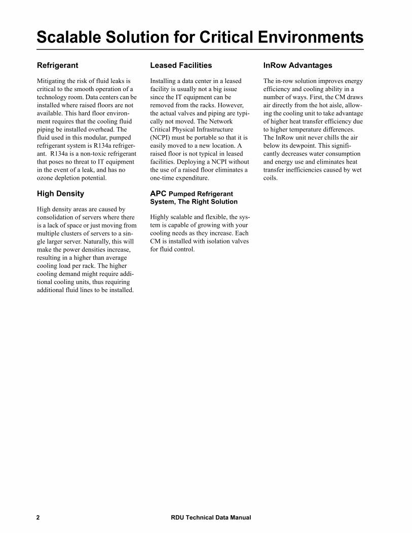
RefrigerantMitigating the risk of fluid leaks is critical to the smooth operation of a technology room. Data centers can be installed where raised floors are not available. This hard floor environ-ment requires that the cooling fluid piping be installed overhead. The fluid used in this modular, pumped refrigerant system is R134a refriger-ant. R134a is a non-toxic refrigerant that poses no threat to IT equipment in the event of a leak, and has no ozone depletion potential.
High Density
High density areas are caused by consolidation of servers where there is a lack of space or just moving from multiple clusters of servers to a sin-gle larger server. Naturally, this will make the power densities increase, resulting in a higher than average cooling load per rack. The higher cooling demand might require addi-tional cooling units, thus requiring additional fluid lines to be installed.
Leased Facilities
Installing a data center in a leased facility is usually not a big issue since the IT equipment can be removed from the racks. However, the actual valves and piping are typi-cally not moved. The Network Critical Physical Infrastructure (NCPI) must be portable so that it is easily moved to a new location. A raised floor is not typical in leased facilities. Deploying a NCPI without the use of a raised floor eliminates a one-time expenditure.
APC Pumped Refrigerant System, The Right Solution
Highly scalable and flexible, the sys-tem is capable of growing with your cooling needs as they increase. Each CM is installed with isolation valves for fluid control.
InRow Advantages
The in-row solution improves energy efficiency and cooling ability in a number of ways. First, the CM draws air directly from the hot aisle, allow-ing the cooling unit to take advantage of higher heat transfer efficiency due to higher temperature differences. The InRow unit never chills the air below its dewpoint. This signifi-cantly decreases water consumption and energy use and eliminates heat transfer inefficiencies caused by wet coils.
RDU Technical Data Manual2
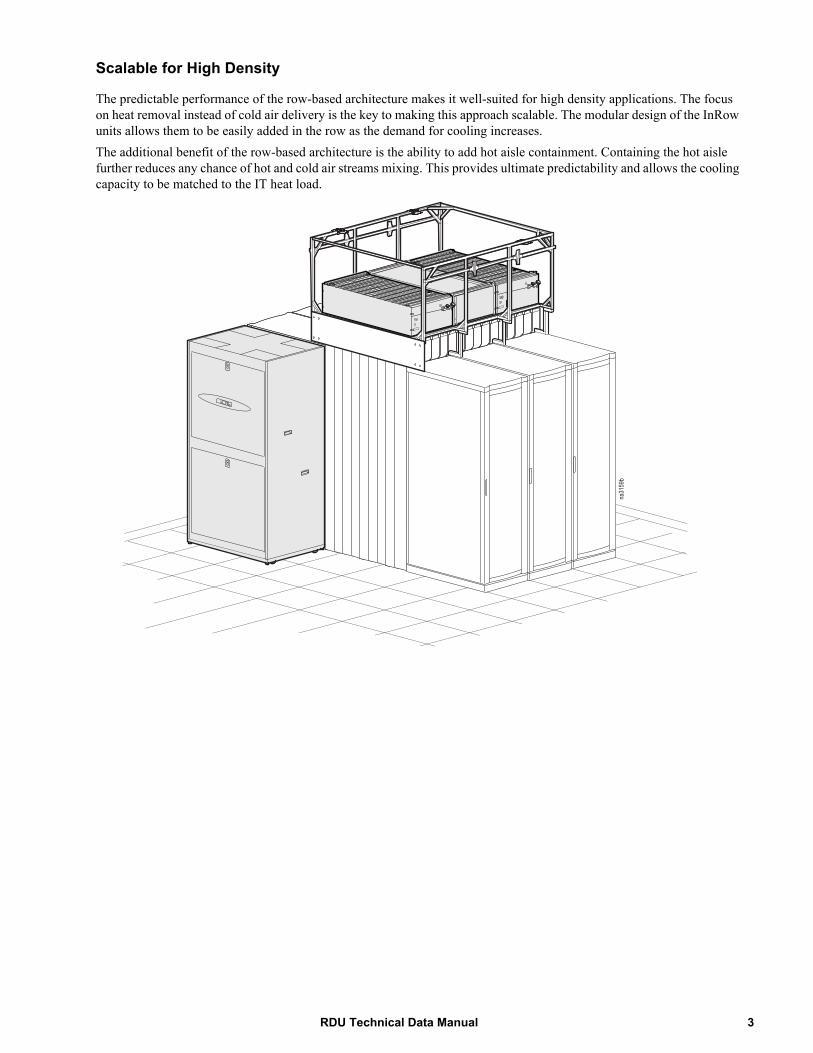
Scalable for High Density
The predictable performance of the row-based architecture makes it well-suited for high density applications. The focus on heat removal instead of cold air delivery is the key to making this approach scalable. The modular design of the InRow units allows them to be easily added in the row as the demand for cooling increases.The additional benefit of the row-based architecture is the ability to add hot aisle containment. Containing the hot aisle further reduces any chance of hot and cold air streams mixing. This provides ultimate predictability and allows the cooling capacity to be matched to the IT heat load.
na31
59b
3RDU Technical Data Manual
Standard Features
CabinetThe frame is constructed of 14 gauge formed steel for maximum strength. The cabinet is serviceable from the front. All exterior panels and corner posts on the frame are powder coated for durability and an attractive finish. The front and rear exterior panels are constructed of 18 gauge steel, and the side panels are constructed of 20 gauge steel. The front panels, which include a key latch for safety and security, allow easy access and removal. All internal pipes are insu-lated with 12.7 mm (1/2 in) closed cell insulation.
Heat Exchanger
The brazed plate heat exchanger is constructed of 316 stainless steel plates. The primary side of the heat exchanger is piped to a chilled water source; the secondary side is piped to the CM.
Redundant Refrigerant Pumps
The two factory-piped and factory-wired pumps are 2N redundant and can automatically adjust the flow of refrigerant for variable capacity of the system.Each pump may be replaced while the unit is in operation without effect-ing system performance.
Microprocessor Control
Users can navigate between menus, select items, and input alpha numeric information using control keys.The microprocessor controller acti-vates a visible and audible alarm in the occurrence of certain events. See “Alarms” on page 6.
2-way/3-way Water Control Valves
The RDU includes a pair of floating point microprocessor-controlled 2-way valves which regulate the amount of chilled water into the heat exchanger to maintain optimal cool-ing conditions for the system. The valves are user configurable to oper-ate in either two-way or three-way mode.
Top or Bottom Power Feed
Electrical power is supplied to the unit via a locking NEMA or IEC plug connection (top wiring only) suitable for the input power.Hard-wired electrical power may be supplied to the unit through top or bottom connections.Dual power feeds allow cooling to remain operational during a power outage to the main power source.
Shutdown Input/Alarm Output
The unit provides one field connec-tion input for remote shutdown and one field connection alarm output.
Selectable Top or Bottom Piping Connections
The unit includes provisions for either top or bottom water piping connections. Piping may be brazed directly to external pipes or to flanges to facilitate ease of discon-necting the RDU.
Network Management Card
The Network Management Card (NMC) allows communication with the Local Area Network (LAN). In addition, the NMC permits multi-level access to monitoring, control, and event notification features over the building network.
Bay Kit-NetShelter SX
Baying kits made of 16 gauge steel are available for baying the RDU to APC NetShelter enclosures.
Insulation Kit
A kit of insulation is provided to pre-vent condensation from internal piping once the piping is installed and connected.
RDU Technical Data Manual4
Optional Features
Flange KitAs an alternative to brazing, a flange kit is available to provide for more easily disconnecting piping.
Rack Door Kit
This kit will allow your RDU to look like the APC equipment racks in the adjacent row.
Flexible Stainless Steel Hoses
914 mm (3 ft) and 1828 mm (6 ft) flexible stainless steel hoses are available for use in installations where standard piping is impractical or not desired.The flexible hoses can be used to connect OAs to the modular piping headers.
Network Cable
Various lengths of network cable are available to ship with your cooling system. The network cable is used to interconnect multiple cooling units in a redundant group, as well as to con-nect the Network Management Card to your LAN.
Pipe Clamp Kit
This kit contains clamps, fasteners, and insulation needed to mount refrigerant piping on the mount frames.
1, 2, And 3-port RDU Piping Kits
This kit provides three optional solu-tions for routing refrigerant to and from the CM. They may be installed directly on the InRow OA mount frames, hung from threaded rod, or attached to support members.
5RDU Technical Data Manual
Microprocessor Controller
ESC
?
Status
CheckLog
Warning
Critical
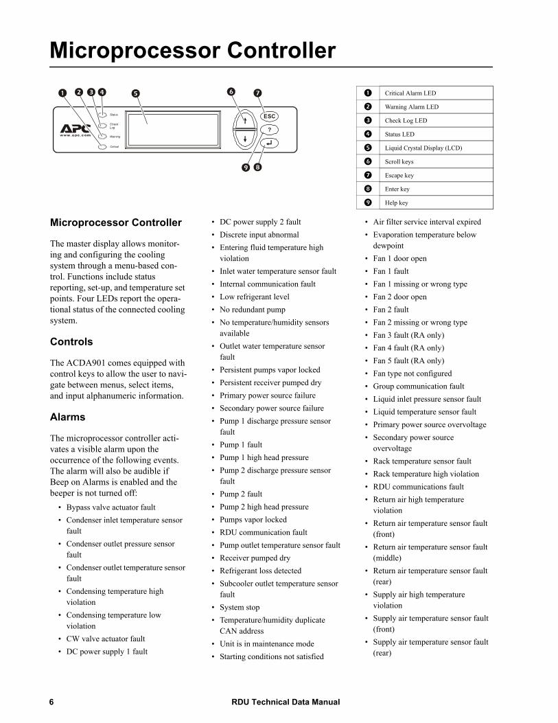
1 Critical Alarm LED
2 Warning Alarm LED
3 Check Log LED
4 Status LED
5 Liquid Crystal Display (LCD)
6 Scroll keys
7 Escape key
8 Enter key
9 Help key
Microprocessor Controller
The master display allows monitor-ing and configuring the cooling system through a menu-based con-trol. Functions include status reporting, set-up, and temperature set points. Four LEDs report the opera-tional status of the connected cooling system.
Controls
The ACDA901 comes equipped with control keys to allow the user to navi-gate between menus, select items, and input alphanumeric information.
Alarms
The microprocessor controller acti-vates a visible alarm upon the occurrence of the following events. The alarm will also be audible if Beep on Alarms is enabled and the beeper is not turned off:
• Bypass valve actuator fault• Condenser inlet temperature sensor
fault• Condenser outlet pressure sensor
fault• Condenser outlet temperature sensor
fault• Condensing temperature high
violation• Condensing temperature low
violation• CW valve actuator fault• DC power supply 1 fault
• DC power supply 2 fault• Discrete input abnormal• Entering fluid temperature high
violation• Inlet water temperature sensor fault• Internal communication fault• Low refrigerant level• No redundant pump• No temperature/humidity sensors
available• Outlet water temperature sensor
fault• Persistent pumps vapor locked• Persistent receiver pumped dry• Primary power source failure• Secondary power source failure• Pump 1 discharge pressure sensor
fault• Pump 1 fault• Pump 1 high head pressure• Pump 2 discharge pressure sensor
fault• Pump 2 fault• Pump 2 high head pressure• Pumps vapor locked• RDU communication fault• Pump outlet temperature sensor fault• Receiver pumped dry• Refrigerant loss detected• Subcooler outlet temperature sensor
fault• System stop• Temperature/humidity duplicate
CAN address• Unit is in maintenance mode• Starting conditions not satisfied
• Air filter service interval expired• Evaporation temperature below
dewpoint• Fan 1 door open• Fan 1 fault• Fan 1 missing or wrong type• Fan 2 door open• Fan 2 fault• Fan 2 missing or wrong type• Fan 3 fault (RA only)• Fan 4 fault (RA only)• Fan 5 fault (RA only)• Fan type not configured• Group communication fault• Liquid inlet pressure sensor fault• Liquid temperature sensor fault• Primary power source overvoltage• Secondary power source
overvoltage• Rack temperature sensor fault• Rack temperature high violation• RDU communications fault• Return air high temperature
violation• Return air temperature sensor fault
(front)• Return air temperature sensor fault
(middle)• Return air temperature sensor fault
(rear)• Supply air high temperature
violation• Supply air temperature sensor fault
(front)• Supply air temperature sensor fault
(rear)
RDU Technical Data Manual6
• Unit ID needs configuration• Unit personality not configured• Vapor outlet pressure sensor failure• Evaporation temperature below dew
point
Logging
The event log keeps a record of all alarms and events. Each event log contains a time/date stamp as well as operating conditions at the time of occurrence. The controller also dis-plays run time (in hours) for major components.
Display Interface
The backlit, four-line by twenty-character display interface is pass-word configurable.
7RDU Technical Data Manual
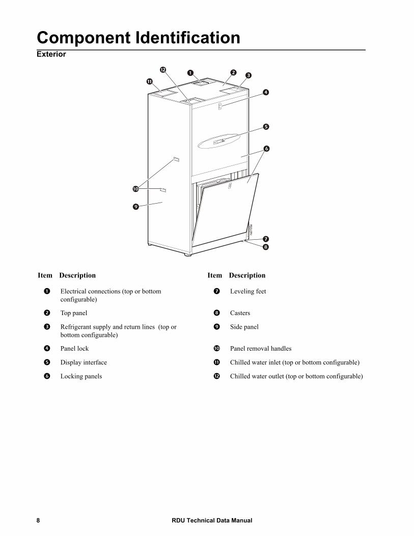
Component IdentificationExterior
Item Description Item Description
1 Electrical connections (top or bottom configurable)
7 Leveling feet
2 Top panel 8 Casters
3 Refrigerant supply and return lines (top or bottom configurable)
9 Side panel
4 Panel lock : Panel removal handles
5 Display interface ; Chilled water inlet (top or bottom configurable)
6 Locking panels < Chilled water outlet (top or bottom configurable)
na31
05a
RDU Technical Data Manual8

Interior
Item Description Item Description
1 Schrader valve : Drip shield
2 Clean out tee ; Refrigerant pumps
3 Brazed plate heat exchanger < Power supply housing
4 Actuator = Rotolock valves
5 User interface > Receiver
6 Nameplate ? Pressure relief valve
7 Electronics board @ Liquid level sensor
8 Subcooler A Electrical receptacles
9 Pressure transducer
na31
06a
9RDU Technical Data Manual
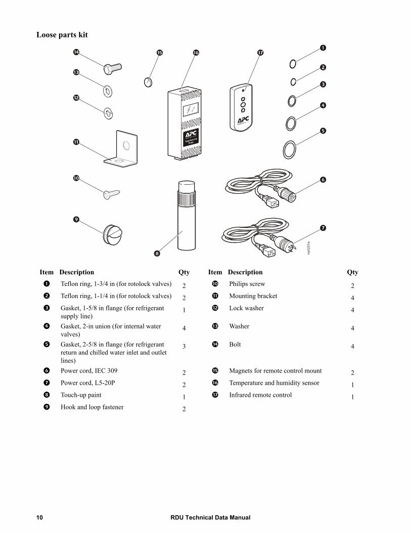
Loose parts kit
Item Description Qty Item Description Qty
1 Teflon ring, 1-3/4 in (for rotolock valves) 2 : Philips screw 2
2 Teflon ring, 1-1/4 in (for rotolock valves) 2 ; Mounting bracket 4
3 Gasket, 1-5/8 in flange (for refrigerant supply line)
1 < Lock washer 4
4 Gasket, 2-in union (for internal water valves)
4 = Washer 4
5 Gasket, 2-5/8 in flange (for refrigerant return and chilled water inlet and outlet lines)
3 > Bolt 4
6 Power cord, IEC 309 2 ? Magnets for remote control mount 2
7 Power cord, L5-20P 2 @ Temperature and humidity sensor 1
8 Touch-up paint 1 A Infrared remote control 1
9 Hook and loop fastener 2
na3251a
RDU Technical Data Manual10
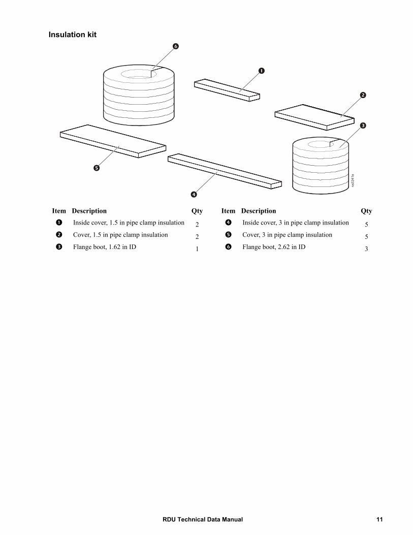
Insulation kit
Item Description Qty Item Description Qty
1 Inside cover, 1.5 in pipe clamp insulation 2 4 Inside cover, 3 in pipe clamp insulation 5
2 Cover, 1.5 in pipe clamp insulation 2 5 Cover, 3 in pipe clamp insulation 5
3 Flange boot, 1.62 in ID 1 6 Flange boot, 2.62 in ID 3
na3241a
11RDU Technical Data Manual
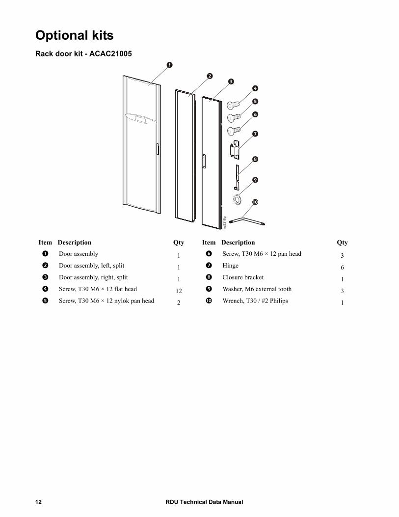
Optional kitsRack door kit - ACAC21005
Item Description Qty Item Description Qty
1 Door assembly 1 6 Screw, T30 M6 × 12 pan head 3
2 Door assembly, left, split 1 7 Hinge 6
3 Door assembly, right, split 1 8 Closure bracket 1
4 Screw, T30 M6 × 12 flat head 12 9 Washer, M6 external tooth 3
5 Screw, T30 M6 × 12 nylok pan head 2 : Wrench, T30 / #2 Philips 1
na3218a
RDU Technical Data Manual12
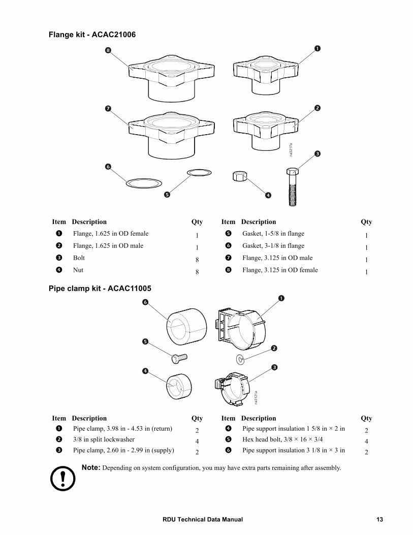
Flange kit - ACAC21006
Pipe clamp kit - ACAC11005
Note: Depending on system configuration, you may have extra parts remaining after assembly.
Item Description Qty Item Description Qty
1 Flange, 1.625 in OD female 1 5 Gasket, 1-5/8 in flange 1
2 Flange, 1.625 in OD male 1 6 Gasket, 3-1/8 in flange 1
3 Bolt 8 7 Flange, 3.125 in OD male 1
4 Nut 8 8 Flange, 3.125 in OD female 1
Item Description Qty Item Description Qty1 Pipe clamp, 3.98 in - 4.53 in (return) 2 4 Pipe support insulation 1 5/8 in × 2 in 22 3/8 in split lockwasher 4 5 Hex head bolt, 3/8 × 16 × 3/4 43 Pipe clamp, 2.60 in - 2.99 in (supply) 2 6 Pipe support insulation 3 1/8 in × 3 in 2
na3217a
na3121a
13RDU Technical Data Manual
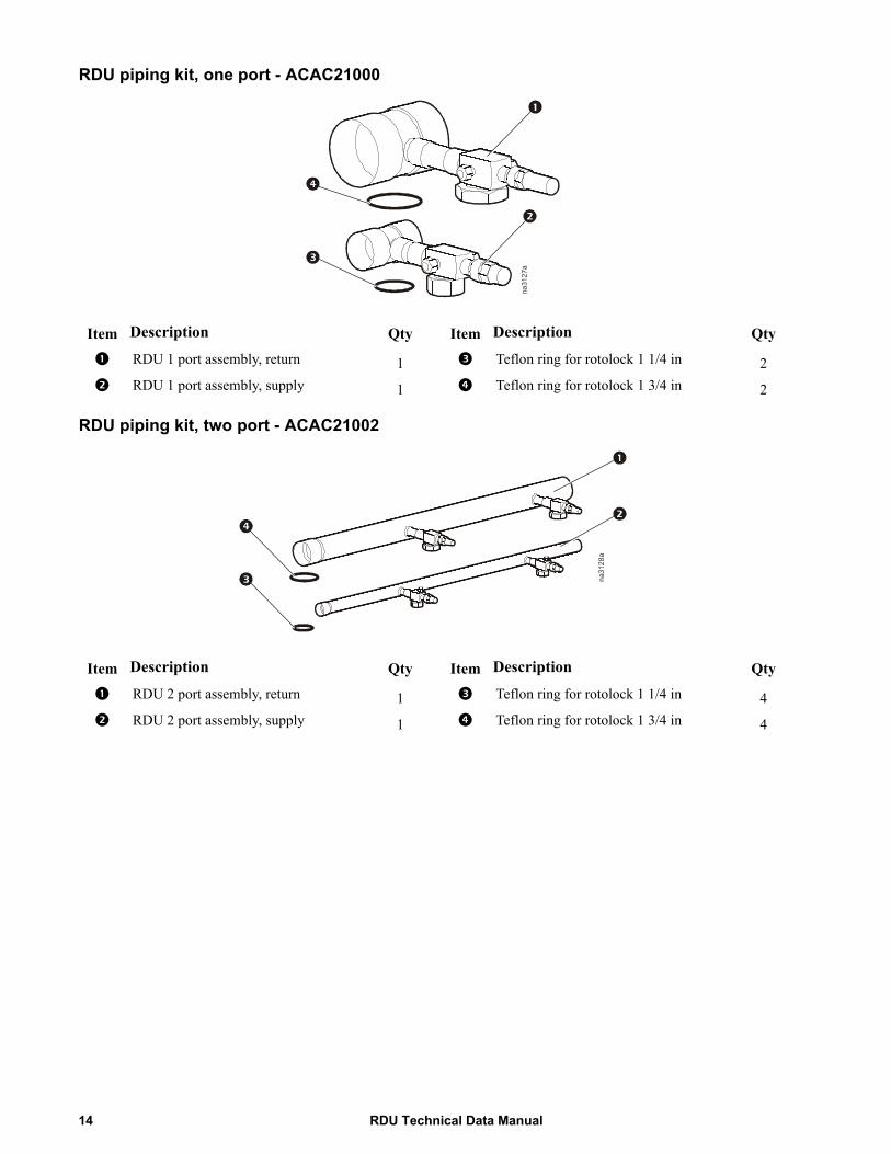
RDU piping kit, one port - ACAC21000
RDU piping kit, two port - ACAC21002
Item Description Qty Item Description Qty
1 RDU 1 port assembly, return 1 3 Teflon ring for rotolock 1 1/4 in 2
2 RDU 1 port assembly, supply 1 4 Teflon ring for rotolock 1 3/4 in 2
Item Description Qty Item Description Qty
1 RDU 2 port assembly, return 1 3 Teflon ring for rotolock 1 1/4 in 4
2 RDU 2 port assembly, supply 1 4 Teflon ring for rotolock 1 3/4 in 4
na3127a
na3128a
RDU Technical Data Manual14
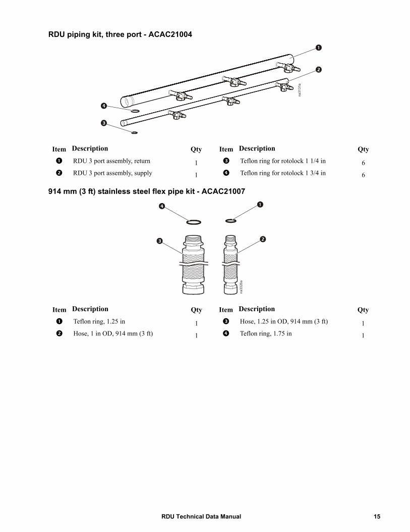
RDU piping kit, three port - ACAC21004
914 mm (3 ft) stainless steel flex pipe kit - ACAC21007
Item Description Qty Item Description Qty
1 RDU 3 port assembly, return 1 3 Teflon ring for rotolock 1 1/4 in 6
2 RDU 3 port assembly, supply 1 4 Teflon ring for rotolock 1 3/4 in 6
Item Description Qty Item Description Qty
1 Teflon ring, 1.25 in 1 3 Hose, 1.25 in OD, 914 mm (3 ft) 1
2 Hose, 1 in OD, 914 mm (3 ft) 1 4 Teflon ring, 1.75 in 1
na3131a
na3326a
15RDU Technical Data Manual
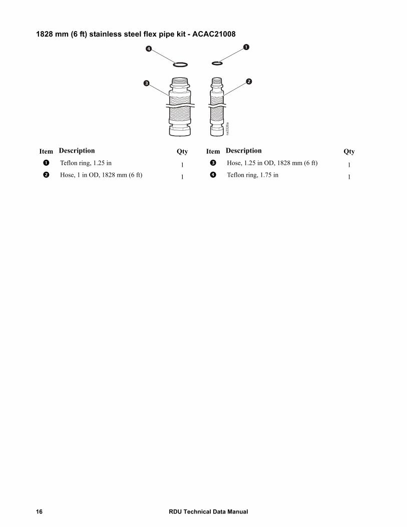
1828 mm (6 ft) stainless steel flex pipe kit - ACAC21008
Item Description Qty Item Description Qty
1 Teflon ring, 1.25 in 1 3 Hose, 1.25 in OD, 1828 mm (6 ft) 1
2 Hose, 1 in OD, 1828 mm (6 ft) 1 4 Teflon ring, 1.75 in 1
na3326a
RDU Technical Data Manual16
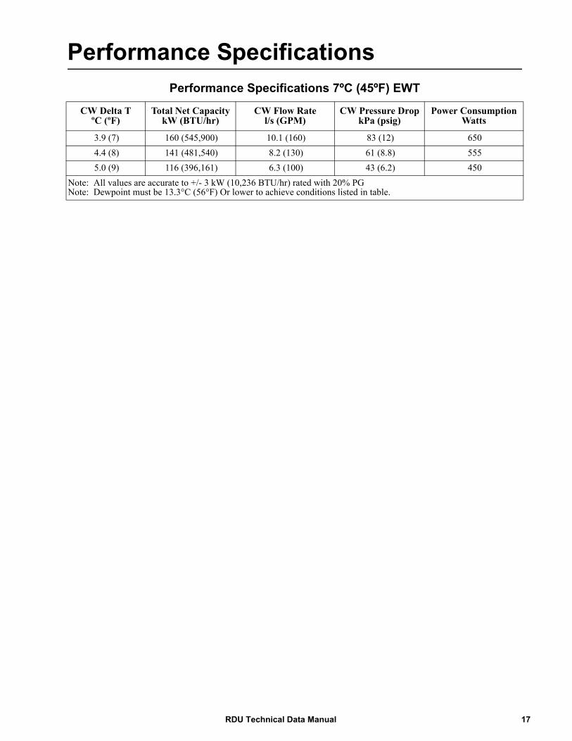
Performance SpecificationsPerformance Specifications 7ºC (45ºF) EWT
CW Delta TºC (ºF)
Total Net Capacity kW (BTU/hr)
CW Flow Ratel/s (GPM)
CW Pressure DropkPa (psig)
Power ConsumptionWatts
3.9 (7) 160 (545,900) 10.1 (160) 83 (12) 6504.4 (8) 141 (481,540) 8.2 (130) 61 (8.8) 5555.0 (9) 116 (396,161) 6.3 (100) 43 (6.2) 450
Note: All values are accurate to +/- 3 kW (10,236 BTU/hr) rated with 20% PGNote: Dewpoint must be 13.3°C (56°F) Or lower to achieve conditions listed in table.
17RDU Technical Data Manual
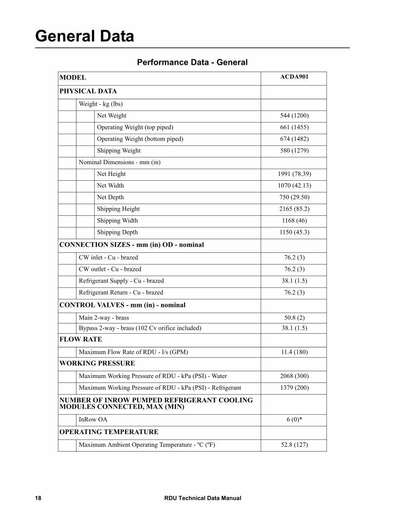
General DataPerformance Data - General
MODEL ACDA901
PHYSICAL DATA
Weight - kg (lbs)
Net Weight 544 (1200)
Operating Weight (top piped) 661 (1455)
Operating Weight (bottom piped) 674 (1482)
Shipping Weight 580 (1279)
Nominal Dimensions - mm (in)
Net Height 1991 (78.39)
Net Width 1070 (42.13)
Net Depth 750 (29.50)
Shipping Height 2165 (85.2)
Shipping Width 1168 (46)
Shipping Depth 1150 (45.3)
CONNECTION SIZES - mm (in) OD - nominal
CW inlet - Cu - brazed 76.2 (3)
CW outlet - Cu - brazed 76.2 (3)
Refrigerant Supply - Cu - brazed 38.1 (1.5)
Refrigerant Return - Cu - brazed 76.2 (3)
CONTROL VALVES - mm (in) - nominal
Main 2-way - brass 50.8 (2)Bypass 2-way - brass (102 Cv orifice included) 38.1 (1.5)
FLOW RATE
Maximum Flow Rate of RDU - l/s (GPM) 11.4 (180)
WORKING PRESSURE
Maximum Working Pressure of RDU - kPa (PSI) - Water 2068 (300)
Maximum Working Pressure of RDU - kPa (PSI) - Refrigerant 1379 (200)
NUMBER OF INROW PUMPED REFRIGERANT COOLING MODULES CONNECTED, MAX (MIN)
InRow OA 6 (0)*
OPERATING TEMPERATURE
Maximum Ambient Operating Temperature - ºC (ºF) 52.8 (127)
RDU Technical Data Manual18

SOUND
Lp Sound Pressure (front unit**) dB re: 20 μPa*** 61 dBAREFRIGERANT
Type R-134a
Unit Charge - kg (lb) MINIMUM 27 (60)
System Charge**** - kg (lb) 77 (170)
WATER
Volume (Top Piped) - liters (gal) 43 (11.3)
Volume (Bottom Piped) - liters (gal) 50.6 (13.4)
Note: Maximum distance between the RDU and the farthest cooling module is 24.4 equivalent meters (80 equivalent feet).* The quantity of 6 OAs is based on a capacity of 25kw per unit. If OAs are operating at less capacity, more units can be piped to an RDU to total 160kW** Unit only tested at 1.0m (3.3 ft) in front of the unit.*** Weighted Sound Pressure dBA in a 1223 m^3 (43,200 ft^3) room at 1.0 m (3.3 ft) distance.**** 6 CMs and maximum piping length
Power Consumption
Total Net CapacitykW (BTU/hr)
Power ConsumptionWatts
160 (545,900) 650140 (478,125) 551120 (409,822) 466100 (341,518) 39480 (273,214) 337
Glycol Correction Factors
Performance Criteria Glycol
Solution
Percent Volume of Solution***
0% 10% 20% 30% 40% 50%
Capacity* Propylene 1.00 1.00 1.00 0.90 0.76 0.64Ethylene 1.00 1.00 1.00 0.90 0.78 0.62
Pressure Drop** Propylene 0.91 0.96 1.00 1.05 1.14 1.22Ethylene 0.93 0.97 1.00 1.03 1.07 1.13
All correction factors are based on 160 GPM (10.1l/s) and 45°F (7.2°C) EWT*Multiply capacity of device or system by factor above for% solution.**Multiply pressure drop of system by factor above for% solution.***Glycol concentrations over 50% are not recommended.
Performance Data - General
19RDU Technical Data Manual
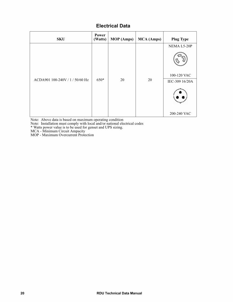
Electrical Data
SKUPower (Watts) MOP (Amps) MCA (Amps) Plug Type
ACDA901 100-240V / 1 / 50/60 Hz 650* 20 20
NEMA L5-20P
100-120 VACIEC-309 16/20A
200-240 VACNote: Above data is based on maximum operating conditionNote: Installation must comply with local and/or national electrical codes* Watts power value is to be used for genset and UPS sizing.MCA - Minimum Circuit AmpacityMOP - Maximum Overcurrent Protection
RDU Technical Data Manual20
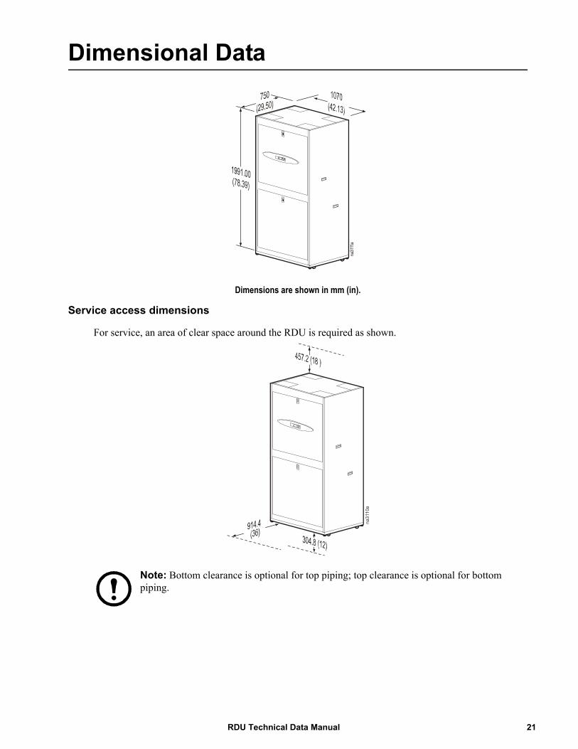
Dimensional Data
Dimensions are shown in mm (in).
Service access dimensions
For service, an area of clear space around the RDU is required as shown.
Note: Bottom clearance is optional for top piping; top clearance is optional for bottom piping.
na31
11a
na3110a
21RDU Technical Data Manual
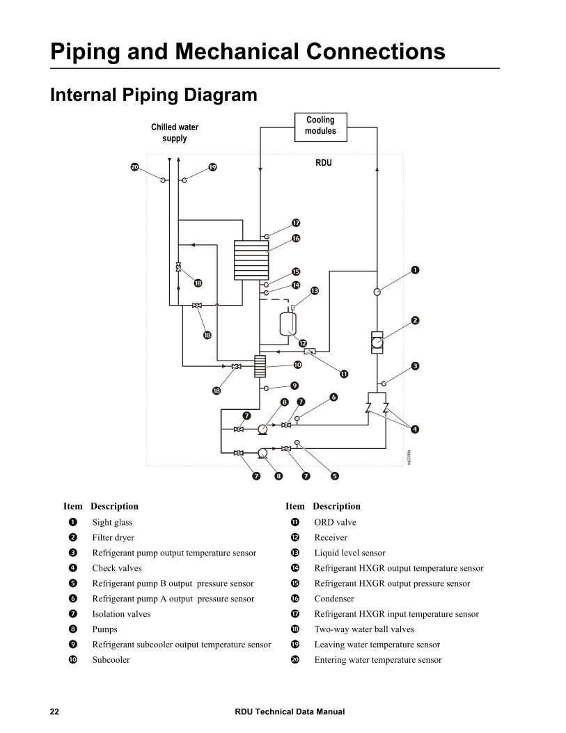
Piping and Mechanical Connections
Internal Piping Diagram
Item Description Item Description
1 Sight glass ; ORD valve
2 Filter dryer < Receiver
3 Refrigerant pump output temperature sensor = Liquid level sensor
4 Check valves > Refrigerant HXGR output temperature sensor
5 Refrigerant pump B output pressure sensor ? Refrigerant HXGR output pressure sensor
6 Refrigerant pump A output pressure sensor @ Condenser
7 Isolation valves A Refrigerant HXGR input temperature sensor
8 Pumps B Two-way water ball valves
9 Refrigerant subcooler output temperature sensor C Leaving water temperature sensor
: Subcooler D Entering water temperature sensor
na33
46a
Cooling modulesChilled water
supply
RDU
RDU Technical Data Manual22
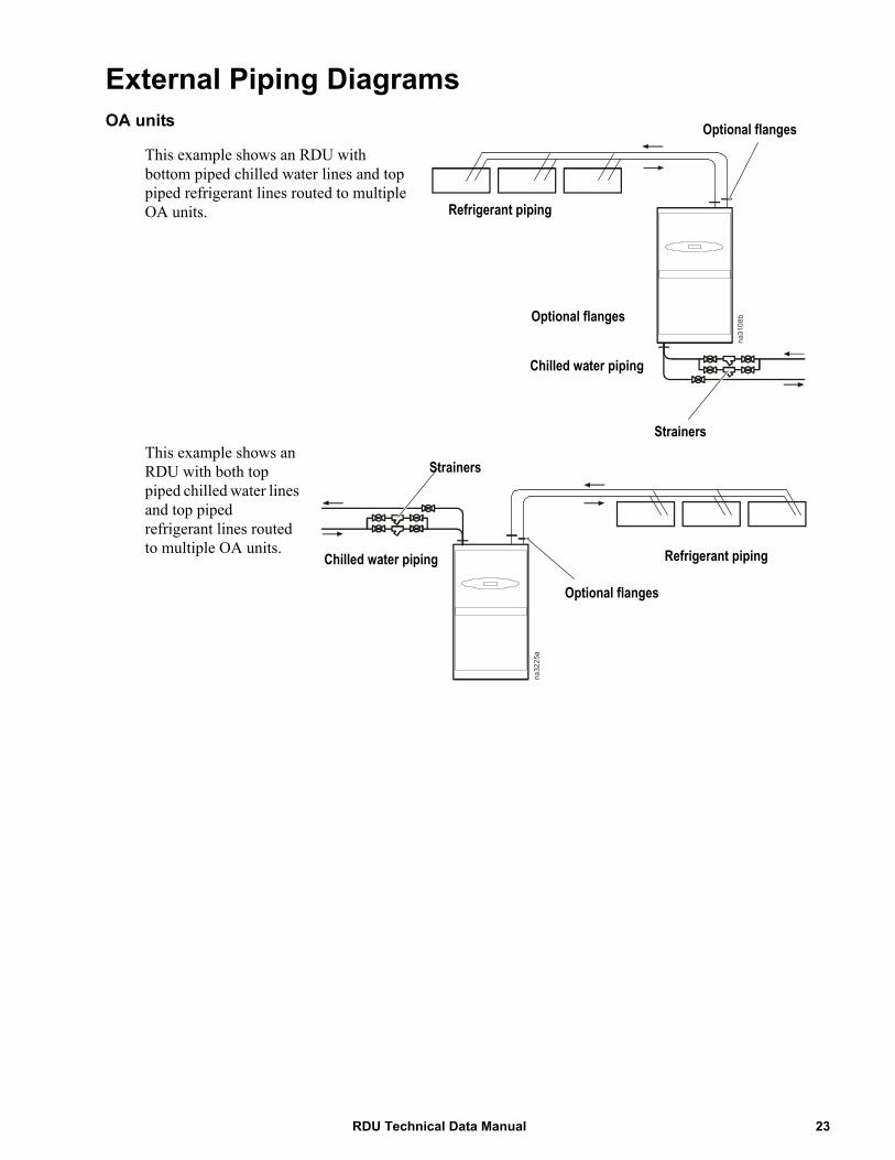
External Piping DiagramsOA units
This example shows an RDU with bottom piped chilled water lines and top piped refrigerant lines routed to multiple OA units.
This example shows an RDU with both top piped chilled water lines and top piped refrigerant lines routed to multiple OA units.
na3108b
Refrigerant piping
Chilled water piping
Strainers
Optional flanges
Optional flanges
na3225a
Optional flanges
Chilled water piping Refrigerant piping
Strainers
23RDU Technical Data Manual
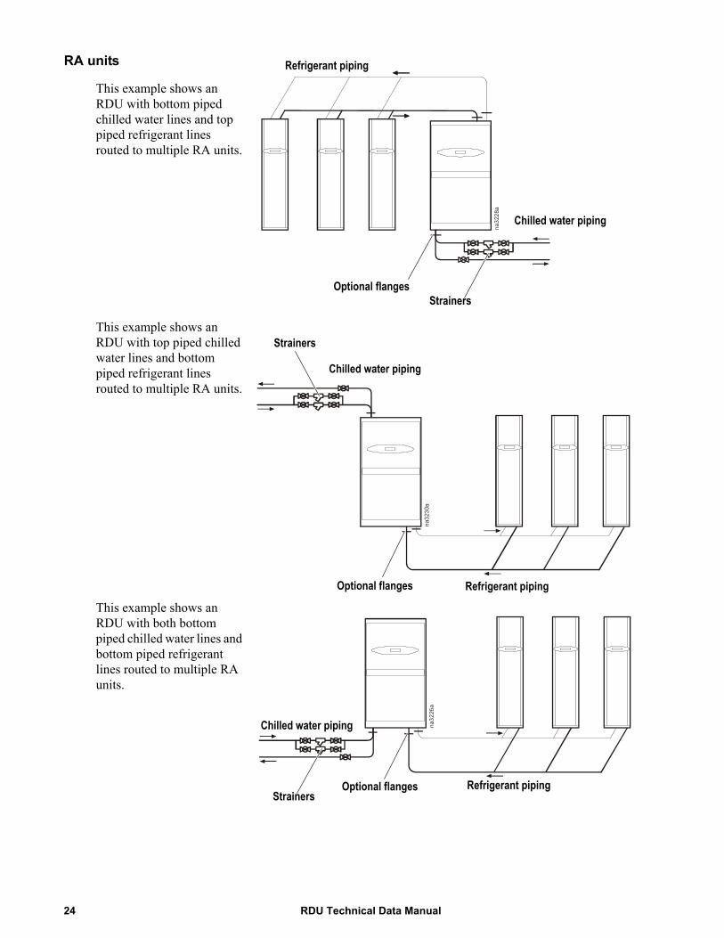
RA units
This example shows an RDU with bottom piped chilled water lines and top piped refrigerant lines routed to multiple RA units.
This example shows an RDU with top piped chilled water lines and bottom piped refrigerant lines routed to multiple RA units.
This example shows an RDU with both bottom piped chilled water lines and bottom piped refrigerant lines routed to multiple RA units.
na3228a
Refrigerant piping
Chilled water piping
Optional flangesStrainers
na3230a
Optional flanges
Strainers
Chilled water piping
Refrigerant piping
na3226a
Strainers
Chilled water piping
Refrigerant pipingOptional flanges
RDU Technical Data Manual24
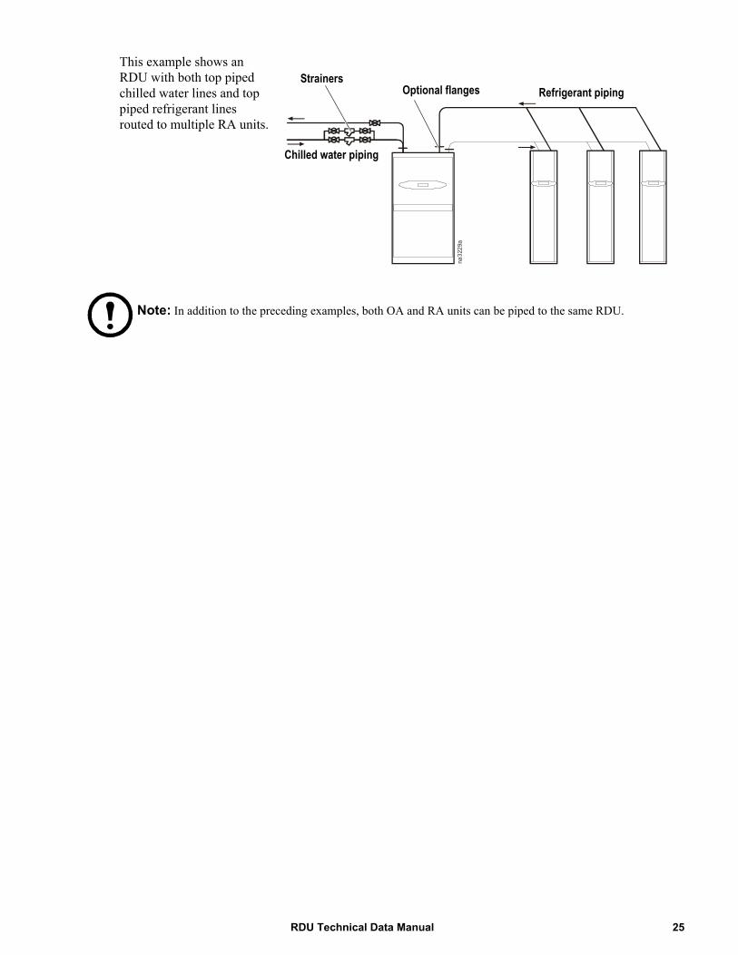
This example shows an RDU with both top piped chilled water lines and top piped refrigerant lines routed to multiple RA units.
Note: In addition to the preceding examples, both OA and RA units can be piped to the same RDU.
StrainersRefrigerant piping
Chilled water piping
na3229a
Optional flanges Refrigerant piping
Chilled water piping
25RDU Technical Data Manual
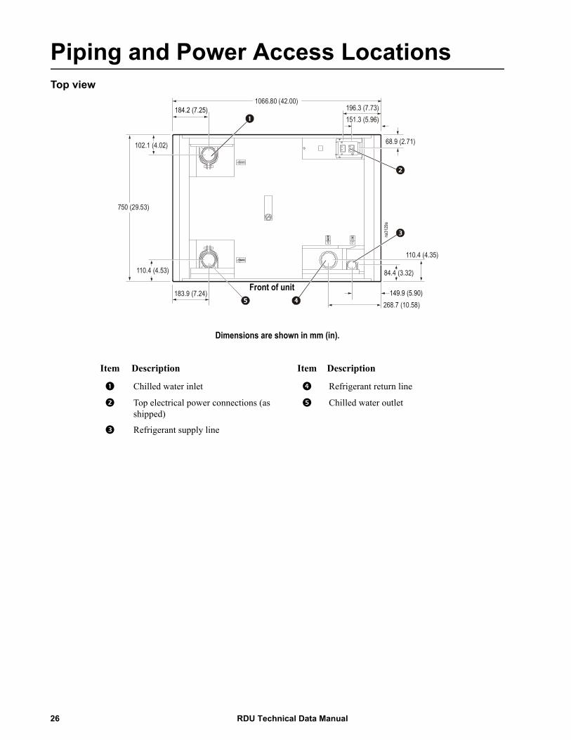
Piping and Power Access LocationsTop view
Dimensions are shown in mm (in).
Item Description Item Description
1 Chilled water inlet 4 Refrigerant return line
2 Top electrical power connections (as shipped)
5 Chilled water outlet
3 Refrigerant supply line
1066.80 (42.00)184.2 (7.25) 196.3 (7.73)
151.3 (5.96)
68.9 (2.71)102.1 (4.02)
750 (29.53)
110.4 (4.53)
183.9 (7.24)
na31
29a
149.9 (5.90)
110.4 (4.35)
84.4 (3.32)
268.7 (10.58)
Front of unit
RDU Technical Data Manual26
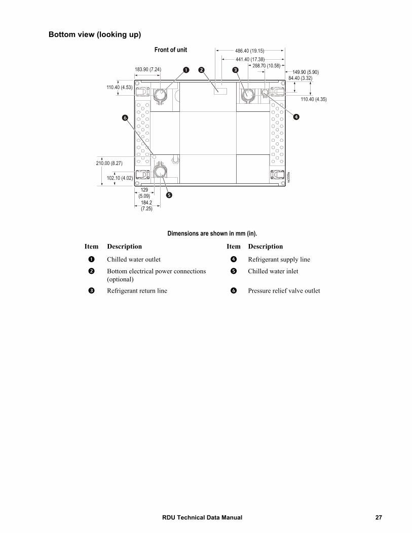
Bottom view (looking up)
Dimensions are shown in mm (in).
Item Description Item Description
1 Chilled water outlet 4 Refrigerant supply line
2 Bottom electrical power connections (optional)
5 Chilled water inlet
3 Refrigerant return line 6 Pressure relief valve outlet
183.90 (7.24)
110.40 (4.53)
184.2(7.25)
129(5.09)
486.40 (19.15)441.40 (17.38)
149.90 (5.90)84.40 (3.32)
110.40 (4.35)
na33
09a
102.10 (4.02)
210.00 (8.27)
Front of unit
27RDU Technical Data Manual
Guide SpecificationsPART 1 — GENERAL
1.01 SUMMARY
A. These specifications describe requirements for a system designed for cooling of IT equipment. The system shall be designed to distribute refrigerant to the row based (close coupled) cooling units.
1.02 DESIGN REQUIREMENTS
A. The RDU shall be manufactured by APC, shall include supply and return refrigerant connections that may be piped to the distribution manifold installed to distribute the refrigerant to the cooling units. The unit shall be as described in the following specification as manufactured by APC.
1.03 SUBMITTALS
A. Submittals shall be provided with the proposal and shall include: overall dimensions of the unit, electrical requirements and capacity data; typical Piping and Electrical Connection drawings.
1.04 QUALITY ASSURANCE
A. The unit shall be factory tested prior to shipment. Testing shall include complete pressure and leak testing to ensure system integrity. The system shall be inspected for quality control before shipment.
B. The unit shall be UL Listed to UL 1995 and CSA C22.2 No. 236.
1.05 WARRANTY
With factory startup, parts and labor shall be provided with a warranty against defects for a period of 12 months from date of shipment from factory. Without factory startup, the warranty is parts only.
PART 1 — STANDARD COMPONENTS
1.01 STANDARD FEATURES
A. The RDU shall include a heat exchanger, redundant pumps, sub-cooler, refrigerant receiver, ACDA901, modulating control valve, dual power feeds, and associated factory piping.
RDU Technical Data Manual28
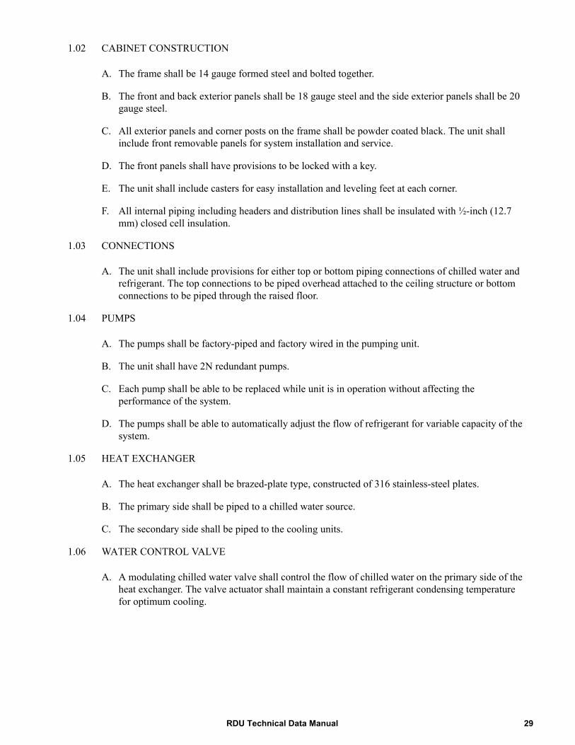
1.02 CABINET CONSTRUCTION
A. The frame shall be 14 gauge formed steel and bolted together.
B. The front and back exterior panels shall be 18 gauge steel and the side exterior panels shall be 20 gauge steel.
C. All exterior panels and corner posts on the frame shall be powder coated black. The unit shall include front removable panels for system installation and service.
D. The front panels shall have provisions to be locked with a key.
E. The unit shall include casters for easy installation and leveling feet at each corner.
F. All internal piping including headers and distribution lines shall be insulated with ½-inch (12.7 mm) closed cell insulation.
1.03 CONNECTIONS
A. The unit shall include provisions for either top or bottom piping connections of chilled water and refrigerant. The top connections to be piped overhead attached to the ceiling structure or bottom connections to be piped through the raised floor.
1.04 PUMPS
A. The pumps shall be factory-piped and factory wired in the pumping unit.
B. The unit shall have 2N redundant pumps.
C. Each pump shall be able to be replaced while unit is in operation without affecting the performance of the system.
D. The pumps shall be able to automatically adjust the flow of refrigerant for variable capacity of the system.
1.05 HEAT EXCHANGER
A. The heat exchanger shall be brazed-plate type, constructed of 316 stainless-steel plates.
B. The primary side shall be piped to a chilled water source.
C. The secondary side shall be piped to the cooling units.
1.06 WATER CONTROL VALVE
A. A modulating chilled water valve shall control the flow of chilled water on the primary side of the heat exchanger. The valve actuator shall maintain a constant refrigerant condensing temperature for optimum cooling.
29RDU Technical Data Manual

1.07 MICROPROCESSOR CONTROLLER
A. Monitoring and Configuration: The master display shall allow monitoring and configuration of the cooling system through a menu-based control. Functions include status reporting, set-up, and temperature set points. Four LEDs report the operational status of the connected cooling system.
B. Controls: The ACDA901 shall come equipped with control keys to allow the user to navigate between menus, select items, and input alpha numeric information.
C. Alarms: The microprocessor controller shall activate a visible and audible alarm in the occurrence of the following events:
1 . Bypass valve actuator fault2 . Condenser inlet temperature sensor fault3 . Condenser outlet pressure sensor fault4 . Condenser outlet temperature sensor fault5 . Condensing temperature high violation6 . Condensing temperature low violation7 . CW valve actuator fault8 . DC power supply 1 fault9 . DC power supply 2 fault
10 . Discrete input abnormal11. Entering fluid temperature high violation12 . Inlet water temperature sensor fault13 . Internal communication fault14 . Low refrigerant level15 . No redundant pump16. No temperature/humidity sensors available17 . Outlet water temperature sensor fault18 . Persistent pumps vapor locked19 . Persistent receiver pumped dry20 . Primary power source failure21 . Secondary power source failure22 . Pump 1 discharge pressure sensor fault23 . Pump 1 fault24 . Pump 1 high head pressure25 . Pump 2 discharge pressure sensor fault26 . Pump 2 fault27 . Pump 2 high head pressure28 . Pumps vapor locked29 . RDU communication fault30 . Pump outlet temperature sensor fault31 . Receiver pumped dry32 . Refrigerant loss detected33 . Subcooler outlet temperature sensor fault34 . System stop35 . Temperature/humidity duplicate CAN address36 . Unit is in maintenance mode37 . Starting conditions not satisfied38 . Water leak detected
RDU Technical Data Manual30
39. Water leak detected warning40 . Air filter service interval expired41 . Evaporation temperature below dewpoint42 . Fan 1 door open43 . Fan 1 fault44 . Fan 1 missing or wrong type45 . Fan 2 door open46 . Fan 2 fault47 . Fan 2 missing or wrong type48 . Fan 3 fault (RA only)49 . Fan 4 fault (RA only)50 . Fan 5 fault (RA only)51 . Fan type not configured52 . Group communication fault53 . Liquid inlet pressure sensor fault54 . Liquid temperature sensor fault55 . Primary power source overvoltage56 . Secondary power source overvoltage57 . Rack temperature sensor fault58 . Rack temperature high violation59 . RDU communications fault60 . Return air high temperature violation61 . Return air temperature sensor fault (front)62 . Return air temperature sensor fault (middle)63 . Return air temperature sensor fault (rear)64 . Supply air high temperature violation65 . Supply air temperature sensor fault (front)66 . Supply air temperature sensor fault (rear)67 . Unit ID needs configuration68 . Unit personality not configured69 . Vapor outlet pressure sensor failure70 . Evaporation temperature below dew point
D. Logging: The microprocessor controller shall log and display all available events. Each alarm log shall contain time/date stamp as well as operating conditions at the time of occurrence. Controller shall display the run time hours for major components.
1.08 NETWORK MANAGEMENT CARD
A. The unit shall include a network management card to provide management through a computer network through TCP/IP. Management through the network should include the ability to change set points as well as view and clear alarms.
31RDU Technical Data Manual
1.09 SELECTABLE TOP OR BOTTOM PIPING
A. Pipe connections for field connection from either the top or bottom of the unit. Unit connections shall be made external to the unit.
B. Piping should be factory insulated with 1/2 inch closed cell neoprene insulation.
1.10 DUAL POWER INPUT
A. Input Power Feeds: Dual power inputs should be a locking NEMA or IEC plug connection suitable for the input power.
1.11 DUAL REFRIGERANT PUMP POWER SUPPLIES
A. Power Supplies: The unit shall include two power supplies, each capable of running the unit at 90% capacity in the event of a single power supply failure.
B. Operation and Service: Power supply shall be replaceable by certified personnel.
PART 2 — IMPLEMENTATION
2.01 INSTALLATION
A. Installation of the system shall be in accordance to the Guidelines for Installation by the manufacturer.
B. Installation shall be performed by the manufacturer or supervised by the manufacturer service representative.
C. Installation of piping and connections from the RDU to the distribution manifold shall be performed be supervised by the manufacturer service representative.
Note: Minimum raised floor height for bottom piping is 18 inches (357.2 mm)
2.02 STARTUP
A. Start up of the RDU shall be performed by the manufacturer.
RDU Technical Data Manual32
Guidelines for InstallationThe RDU provides cooled refrigerant to InRow cooling modules (CM) to achieve reliable, accurate temperature control of computer rooms, laboratories, and other environments that require close tolerance control. The unit incorporates the latest system design innovations to provide you with optimum efficiency, reliability, and accuracy of control.
The RDU unit will provide years of trouble-free service when installed and maintained by technically qualified personnel. For more detailed information, see the appropriate RDU Installation manual.
Room preparationDuring the design of the data center, consider ease of entry for the equipment, floor loading factors, and accessibility to piping and wiring.Seal the room with a vapor barrier to minimize moisture infiltration. (Polyethylene film is recommended for ceiling and wall applications.) Apply rubber or plastic based paints to concrete walls and floors.Insulate the room to minimize the influence of exterior heat loads. Use the minimum required amount of fresh air for make up to comply with local and national codes and regulations. Fresh air imposes extreme load variation on the cooling equipment from summer to winter and causes increased group operating costs.
Service accessFor installation, at least 914 mm (36 in) of clear space must be left in the front of the unit.
Receiving the unitYour RDU has been completely tested and inspected prior to shipment. To ensure that you have received the unit in excellent condition, perform a careful inspection of the crating and the unit immediately upon receipt. Verify that all parts ordered were received as specified. Report any damage discovered to the freight carrier. If necessary, contact the APC field service department for help in repairing or replacing damaged parts. While APC is not responsible for damage incurred in transit, we want to make sure that you have no undue delays in your system start-up. See the unpacking sheet and installation manual for more information.
RiggingThe unit is manufactured with a formed steel frame for maximum strength and unit integrity. However, as with all electrical and mechanical equipment, you must take care with proper rigging of your unit. When using a forklift to move the unit, use the shipping skid to protect the bottom of the unit. When using chains, cables, or rope to lift the unit, use spreader bars to prevent damage to the finished panels. Four threaded M10X16 holes are provided in the top of the frame to accommodate lifting eye bolts that can be utilized to lift the unit.
33RDU Technical Data Manual


7/2010990-3611-001
APC Worldwide Customer SupportCustomer support for this or any other APC product is available at no charge in any of the following ways:
• Visit the APC Web site to access documents in the APC Knowledge Base and to submit customer support requests.– www.apc.com (Corporate Headquarters)
Connect to localized APC Web sites for specific countries, each of which provides customer support information.
– www.apc.com/support/Global support searching APC Knowledge Base and using e-support.
• Contact the APC Customer Support Center by telephone or e-mail.– Local, country-specific centers: go to www.apc.com/support/contact for contact information.
For information on how to obtain local customer support, contact the APC representative or other distributors from whom you purchased your APC product.
© 2010 APC by Schneider Electric. APC, the APC logo, and InRow are owned by Schneider Electric Industries S.A.S., American Power Conversion Corporation, or their affiliated companies. All other
trademarks are property of their respective owners.