OWNER'S MANUAL 2013 990 Supermoto R EU 990 ...
212
OWNER'S MANUAL 2013 990 Supermoto R EU 990 Supermoto R FR 990 Supermoto R AUS/UK Art. no. 3211959en
-
Upload
khangminh22 -
Category
Documents
-
view
0 -
download
0
Transcript of OWNER'S MANUAL 2013 990 Supermoto R EU 990 ...

OWNER'S MANUAL 2013
990 Supermoto R EU990 Supermoto R FR
990 Supermoto R AUS/UKArt. no. 3211959en

DEAR KTM CUSTOMER 1
DEAR KTM CUSTOMER
Congratulations on your decision to purchase a KTM motorcycle. You are now the owner of a state-of-the-art sports motorcycle that willgive you enormous pleasure if you service and maintain it accordingly.
We wish you a lot of enjoyment in riding this vehicle.
Please enter the serial numbers of your vehicle below.
Chassis number/type label Dealer's stamp
Engine number ( p. 21)
Key number ( p. 21)
The owner's manual contained the latest information for this model at the time of going to print. Minor differences due to developments indesign cannot be ruled out completely.
All specifications are non-binding. KTM Sportmotorcycle AG specifically reserves the right to modify or delete technical specifications,prices, colors, forms, materials, services, designs, equipment, etc., without prior notice and without specifying reasons, to adapt theseto local conditions, as well as to stop production of a particular model without prior notice. KTM accepts no liability for delivery options,deviations from illustrations and descriptions, as well as misprints and other errors. The models portrayed partly contain special equipmentthat does not belong to the regular scope of supply.
© 2012 KTM-Sportmotorcycle AG, Mattighofen AustriaAll rights reservedReproduction, even in part, as well as copying of all kinds, is permitted only with the express written permission of the copyright owner.
DEAR KTM CUSTOMER 2
ISO 9001(12 100 6061)According to the international quality management standard ISO 9001, KTM uses quality assurance processes that lead tothe maximum possible quality of the products.Issued by: TÜV Management Service
KTM-Sportmotorcycle AG5230 Mattighofen, Austria

TABLE OF CONTENTS 3
TABLE OF CONTENTS
1 MEANS OF REPRESENTATION ........................................ 71.1 Symbols used ...................................................... 71.2 Formats used....................................................... 7
2 SAFETY ADVICE.............................................................. 82.1 Use definition - intended use ................................ 82.2 Safety advice....................................................... 82.3 Degrees of risk and symbols .................................. 92.4 Tampering warning............................................... 92.5 Safe operation ................................................... 102.6 Protective clothing ............................................. 112.7 Work rules......................................................... 112.8 Environment...................................................... 112.9 Owner's Manual ................................................. 12
3 IMPORTANT NOTES...................................................... 133.1 Guarantee, warranty ........................................... 133.2 Operating substances ......................................... 133.3 Spare parts, accessories ..................................... 133.4 Service ............................................................. 133.5 Figures ............................................................. 143.6 Customer service................................................ 14
4 VIEW OF VEHICLE ........................................................ 164.1 View of vehicle, front left side (example) .............. 164.2 View of vehicle, rear right side (vehicle differs
slightly from photo) ............................................ 185 SERIAL NUMBERS ....................................................... 20
5.1 Chassis number ................................................. 205.2 Type label ......................................................... 205.3 Key number....................................................... 215.4 Engine number .................................................. 21
5.5 Fork part number ............................................... 225.6 Shock absorber part number ............................... 22
6 CONTROLS................................................................... 236.1 Clutch lever....................................................... 236.2 Hand brake lever................................................ 236.3 Throttle grip ...................................................... 246.4 Horn button....................................................... 246.5 Light switch ...................................................... 256.6 Headlight flasher switch ..................................... 256.7 Turn signal switch.............................................. 266.8 Emergency OFF switch ....................................... 266.9 Electric starter button......................................... 276.10 Ignition/steering lock.......................................... 276.11 Immobilizer ....................................................... 286.12 Combination instrument ..................................... 286.12.1 Overview ....................................................... 286.12.2 Function buttons ........................................... 296.12.3 Tachometer ................................................... 296.12.4 indicator lamps.............................................. 306.12.5 Display ......................................................... 316.12.6 Speed display................................................ 326.12.7 Setting kilometers or miles ............................. 326.12.8 Time............................................................. 336.12.9 Setting the clock ........................................... 336.12.10 ODO display .................................................. 346.12.11 Setting/resetting display TRIP 1 ...................... 346.12.12 Setting/resetting display TRIP 2 ...................... 356.12.13 TRIP F display............................................... 366.12.14 Ambient temperature indicator........................ 36
TABLE OF CONTENTS 4
6.12.15 Setting the temperature units.......................... 366.12.16 Warning of icy roads....................................... 376.12.17 Coolant temperature indicator ......................... 386.13 Opening the filler cap......................................... 386.14 Closing the filler cap .......................................... 396.15 Seat lock........................................................... 406.16 Tool set............................................................. 406.17 Handrails .......................................................... 416.18 Helmet lock....................................................... 416.19 Passenger footrests ............................................ 426.20 Shift lever ......................................................... 426.21 Foot brake lever ................................................. 436.22 Side stand......................................................... 44
7 PREPARING FOR USE................................................... 457.1 Information on first use ...................................... 457.2 Running in the engine ........................................ 467.3 Loading the vehicle ............................................ 46
8 RIDING INSTRUCTIONS................................................ 498.1 Checks and maintenance measures when
preparing for use................................................ 498.2 Starting............................................................. 508.3 Starting off........................................................ 528.4 Shifting, riding .................................................. 528.5 Braking ............................................................. 558.6 Stopping, parking............................................... 578.7 Transport .......................................................... 588.8 Refueling .......................................................... 59
9 SERVICE SCHEDULE .................................................... 619.1 Service schedule................................................ 61
10 TUNING THE CHASSIS ................................................. 6410.1 Fork/shock absorber ........................................... 6410.2 Adjusting the compression damping of the fork..... 6410.3 Adjusting the rebound damping of the fork ........... 6510.4 Adjusting the spring preload of the fork................ 6610.5 Compression damping of the shock absorber......... 6810.6 Adjusting the low-speed compression damping of
the shock absorber ............................................. 6810.7 Adjusting the high-speed compression damping
of the shock absorber ......................................... 6910.8 Adjusting the rebound damping of the shock
absorber............................................................ 7010.9 Adjusting the spring preload of the shock
absorberx....................................................... 7111 SERVICE WORK ON THE CHASSIS................................. 73
11.1 Raising the motorcycle with the rear wheelstand ................................................................ 73
11.2 Taking the motorcycle off of the rear wheelstand ................................................................ 73
11.3 Raising the motorcycle with the front wheelstand ................................................................ 74
11.4 Taking the motorcycle off of the front wheelstand ................................................................ 74
11.5 Bleeding the fork legs......................................... 7511.6 Removing the seat ............................................. 7511.7 Mounting the seat .............................................. 7611.8 Reinstalling the fuel tank.................................... 7611.9 Positioning the fuel tank..................................... 7711.10 Mounting the helmet lock on the vehicle .............. 7911.11 Checking the chain for dirt.................................. 80

TABLE OF CONTENTS 5
11.12 Cleaning the chain ............................................. 8011.13 Checking the chain tension ................................. 8111.14 Adjusting the chain tension................................. 8211.15 Checking the chain, rear sprocket, engine
sprocket and chain guide.................................... 8411.16 Adjusting the basic position of the clutch lever ..... 8711.17 Checking/rectifying the fluid level of the
hydraulic clutch................................................. 8712 BRAKE SYSTEM ........................................................... 89
12.1 ABS/antilock brake system.................................. 8912.2 Adjusting the basic position of the hand brake
lever ................................................................. 9012.3 Checking the front brake discs ............................ 9012.4 Checking the front brake fluid level ..................... 9112.5 Adding front brake fluidx................................. 9212.6 Checking the front brake linings .......................... 9312.7 Checking the free travel of the foot brake lever...... 9412.8 Adjusting the basic position of the foot brake
lever ................................................................. 9512.9 Checking the rear brake disc ............................... 9612.10 Checking the rear brake fluid level....................... 9612.11 Adding rear brake fluidx .................................. 9712.12 Checking the rear brake linings ........................... 99
13 WHEELS, TIRES ......................................................... 10113.1 Removing the front wheelx ............................ 10113.2 Installing the front wheelx ............................. 10213.3 Removing the rear wheelx.............................. 10413.4 Installing the rear wheelx .............................. 10613.5 Checking the rear hub rubber dampersx.......... 108
13.6 Checking the tire condition ............................... 10913.7 Checking the tire air pressure............................ 110
14 ELECTRICAL SYSTEM ................................................. 11214.1 Removing the batteryx .................................. 11214.2 Installing the batteryx ................................... 11414.3 Recharging the batteryx ................................ 11514.4 Changing the main fuse.................................... 11714.5 Changing the ABS fuses ................................... 11914.6 Changing the fuses of individual power
consumers....................................................... 12014.7 Changing the headlight bulb ............................. 12214.8 Changing the parking light bulb......................... 12514.9 Changing the turn signal bulb ........................... 12714.10 Changing the brake light bulb ........................... 12814.11 Changing the tail light bulbs ............................. 13214.12 Changing the license plate lamp........................ 13614.13 Checking the headlight setting .......................... 13814.14 Adjusting the headlight range............................ 13814.15 Activating/deactivating the ignition key .............. 139
15 COOLING SYSTEM...................................................... 14415.1 Cooling system ................................................ 14415.2 Checking the antifreeze and coolant level ........... 14415.3 Checking the coolant level in the compensating
tank................................................................ 14715.4 Draining the coolantx .................................... 14815.5 Filling/bleeding the cooling systemx ............... 149
16 TUNING THE ENGINE................................................. 15216.1 Checking the play in the throttle cable ............... 15216.2 Adjusting the play in the throttle cablex.......... 153
TABLE OF CONTENTS 6
16.3 Plug-in connection, ignition timing map............. 15316.4 Adjusting the ignition curve to the fuel quality .... 15416.5 Checking the basic position of the shift lever ...... 15516.6 Adjusting the basic position of the shift
leverx .......................................................... 15517 SERVICE WORK ON THE ENGINE ................................ 157
17.1 Checking the engine oil level............................. 15717.2 Changing the engine oil and filter, cleaning the
oil screensx.................................................. 15817.3 Draining the engine oil, changing the oil filter,
and cleaning the oil screensx......................... 15817.4 Filling up with engine oilx ............................. 16317.5 Adding engine oil ............................................. 164
18 CLEANING, CARE ....................................................... 16518.1 Cleaning motorcycle ......................................... 16518.2 Checks and maintenance measures for winter
operation......................................................... 16719 STORAGE................................................................... 169
19.1 Storage ........................................................... 16919.2 Preparing for use after storage........................... 171
20 TROUBLESHOOTING .................................................. 17221 IMMOBILIZER BLINK CODE ........................................ 17522 ENGINE CONTROL BLINK CODE.................................. 17723 TECHNICAL DATA....................................................... 183
23.1 Engine ............................................................ 18323.2 Engine tightening torques ................................. 18423.3 Capacities ....................................................... 18723.3.1 Engine oil ................................................... 18723.3.2 Coolant ....................................................... 18723.3.3 Fuel ........................................................... 188
23.4 Chassis ........................................................... 18823.5 Electrical system.............................................. 18923.6 Tires ............................................................... 19023.7 Fork................................................................ 19123.8 Shock absorber ................................................ 19223.9 Chassis tightening torques ................................ 193
24 SUBSTANCES ............................................................ 19725 AUXILIARY SUBSTANCES ........................................... 20126 STANDARDS .............................................................. 204INDEX ............................................................................... 205
1 MEANS OF REPRESENTATION 7
1.1 Symbols usedThe meaning of specific symbols is described below.
Indicates an expected reaction (e.g. of a work step or a function).
Indicates an unexpected reaction (e.g. of a work step or a function).
All work marked with this symbol requires specialist knowledge and technical understanding. In the interest of yourown safety, have these jobs performed by an authorized KTM workshop. There, your motorcycle will be optimallycared for by specially trained experts using the specialist tools required.
Indicates a page reference (more information is provided on the specified page).
1.2 Formats usedThe typographical formats used in this document are explained below.
Specific name Identifies a proprietary name.
Name® Identifies a protected name.
Brand™ Identifies a brand available on the open market.

2 SAFETY ADVICE 8
2.1 Use definition - intended useKTM sport motorcycles are designed and constructed to meet the normal demands of regular road operation and also for use on racecourses, but not for offroad use.
InfoThe motorcycle is only authorized for operation on public roads in the homologated version.
2.2 Safety adviceA number of safety instructions need to be followed to operate the vehicle safely. Therefore, read this manual carefully. The safety instruc-tions are highlighted in the text and are referred to at the relevant passages.
InfoThe vehicle has various information and warning labels at prominent locations. Do not remove information/warning labels. If theyare missing, you or others may not recognize dangers and may therefore be injured.

2 SAFETY ADVICE 9
2.3 Degrees of risk and symbols
DangerIdentifies a danger that will immediately and invariably lead to fatal or serious permanent injury if the appropriate measures are nottaken.
WarningIdentifies a danger that is likely to lead to fatal or serious injury if the appropriate measures are not taken.
CautionIdentifies a danger that may lead to minor injuries if the appropriate measures are not taken.
NoteIdentifies a danger that will lead to considerable machine and material damage if the appropriate measures are not taken.
WarningIdentifies a danger that will lead to environmental damage if the appropriate measures are not taken.
2.4 Tampering warningTampering with the noise control system is prohibited. Federal law prohibits the following acts or the causing thereof:
1 The removal or rendering inoperative by any person other than for purposes of maintenance, repair, or replacement, of any device orelement of design incorporated into any new vehicle for the purpose of noise control prior to its sale or delivery to the ultimate pur-chaser or while it is in use, or
2 the use of the vehicle after such device or element of design has been removed or rendered inoperative by any person.
Among those acts presumed to constitute tampering are the acts listed below:

2 SAFETY ADVICE 10
1 Removal or puncturing of the main silencer, baffles, header pipes or any other components which conduct exhaust gases.
2 Removal or puncturing of any part of the intake system.
3 Lack of proper maintenance.
4 Replacing any moving part of the vehicle, or parts of the exhaust or intake system, with parts other than those specified by the manu-facturer.
2.5 Safe operation
DangerDanger of accidents Danger arising from the rider's judgement being impaired.
– Do not operate the vehicle while under the influence of alcohol, drugs and certain medications or physically or mentallyimpaired.
DangerDanger of poisoning Exhaust gases are toxic and inhaling them may result in unconsciousness and/or death.
– When running the engine, always make sure there is sufficient ventilation, and do not start or run the engine in an enclosedspace without an effective exhaust extraction system.
WarningDanger of burns Some vehicle components become very hot when the vehicle is operated.
– Do not touch hot components such as exhaust system, radiator, engine, shock absorber, and the brake system. Allow thesecomponents to cool down before starting work on them.
Only operate the vehicle when it is in perfect technical condition, in accordance with its intended use, and in a safe and environmentallycompatible manner.The vehicle should only be used by trained persons. An appropriate driver's license is needed to ride the vehicle on public roads.Have malfunctions that impair safety promptly eliminated by an authorized KTM workshop.Adhere to the information and warning labels on the vehicle.

2 SAFETY ADVICE 11
2.6 Protective clothing
WarningRisk of injury Missing or poor protective clothing presents an increased safety risk.
– Wear protective clothing (helmet, boots, gloves, pants and jacket with protectors) every time you ride the vehicle. Always wearprotective clothing that is in good condition and meets the legal requirements.
In the interest of your own safety, KTM recommends that you only operate the vehicle while wearing protective clothing.
2.7 Work rulesSpecial tools are necessary for certain tasks. The tools are not contained in the vehicle but can be ordered under the number in parenthe-ses. E.g.: bearing puller (15112017000)During assembly, non-reusable parts (e.g. self-locking screws and nuts, seals and seal rings, O-rings, pins, lock washers) must be replacedby new parts.In some instances, a thread locker (e.g. Loctite®) is required. The manufacturer instructions for use must be followed.After disassembly, clean the parts that are to be reused and check them for damage and wear. Change damaged or worn parts.After you complete the repair or service work, check the operating safety of the vehicle.
2.8 EnvironmentIf you use your motorcycle responsibly, you can ensure that problems and conflicts do not occur. To protect the future of the motorcyclesport, make sure that you use your motorcycle legally, display environmental consciousness, and respect the rights of others.When disposing of used oil, other operating and auxiliary fluids, and used components, comply with the laws and regulations of therespective country.Because motorcycles are not subject to the EU regulations governing the disposal of used vehicles, there are no legal regulations that per-tain to the disposal of an end-of-life motorcycle. Your authorized KTM dealer will be glad to advise you.

2 SAFETY ADVICE 12
2.9 Owner's ManualIt is important that you read this Owner's Manual carefully and completely before making your first trip. The Owner's Manual contains use-ful information and many tips on how to operate, handle, and maintain your motorcycle. Only then will you find out how to customize thevehicle ideally for your own use and how you can protect yourself from injury.Keep the Owner's Manual in an accessible place to enable you to refer to it as needed.If you would like to know more about the vehicle or have questions on the material you read, please contact an authorized KTM dealer.The Owner's Manual is an important component of the vehicle and should be handed over to the new owner if the vehicle is sold.

3 IMPORTANT NOTES 13
3.1 Guarantee, warrantyThe work prescribed in the service schedule must be carried out by an authorized KTM workshop only and confirmed in the customer'sservice record and in the KTM dealer.net; otherwise, all warranty claims will be void. No warranty claims can be considered for damageresulting from manipulations and/or alterations to the vehicle.Additional information on the guarantee or warranty and the procedures involved can be found in the service record.
3.2 Operating substancesThe fuels and lubricants named in the owner's manual must be used according to specifications.
3.3 Spare parts, accessoriesFor your own safety, only use spare parts and accessory products that are approved and/or recommended by KTM and have them installedby an authorized KTM workshop. KTM accepts no liability for other products and any resulting damage or loss.Certain spare parts and accessory products are specified in parentheses in the descriptions. Your KTM dealer will be glad to advise you.
The current KTM PowerParts for your vehicle can be found on the KTM website.International KTM Website: http://www.ktm.com
3.4 ServiceA prerequisite for perfect operation and prevention of premature wear is that the service, care, and tuning work on the engine and chassisis properly carried out as described in the Owner's Manual. Incorrect adjustment and tuning of the engine and chassis can lead to damageand breakage of components.Use of the vehicle under difficult conditions, such in rain, high heat or with a heavy load, can lead to considerably more rapid wear ofcomponents such as the drive train, brake system, or suspension components. For this reason, it may be necessary to inspect or replaceparts before the next scheduled service.It is imperative that you adhere to the stipulated run-in times and service intervals. If you observe these exactly, you will ensure a muchlonger service life for your motorcycle.

3 IMPORTANT NOTES 14
3.5 FiguresThe figures contained in the manual may depict special equipment.In the interest of clarity, some components may be shown disassembled or may not be shown at all. It is not always necessary to disassem-ble the component to perform the activity in question. Please follow the instructions in the text.
3.6 Customer serviceYour authorized KTM dealer will be happy to answer any questions you may have on your vehicle and KTM.
A list of authorized KTM dealers can be found on the KTM website.International KTM Website: http://www.ktm.com

15

4 VIEW OF VEHICLE 16
4.1 View of vehicle, front left side (example)
C00346-10

4 VIEW OF VEHICLE 17
1 Rear mirror
2 Clutch lever ( p. 23)
3 Seat
4 Handrails ( p. 41)
5 Level viewer, engine oil
6 Shift lever ( p. 42)
7 Engine number ( p. 21)
8 Compression damping of the shock absorber ( p. 68)

4 VIEW OF VEHICLE 18
4.2 View of vehicle, rear right side (vehicle differs slightly from photo)
101566-10

4 VIEW OF VEHICLE 19
1 Seat lock ( p. 40)
2 Light switch ( p. 25)
2 Headlight flasher switch ( p. 25)
2 Turn signal switch ( p. 26)
2 Horn button ( p. 24)
3 Filler cap
4 Emergency OFF switch ( p. 26)
4 Electric starter button ( p. 27)
5 Hand brake lever ( p. 23)
6 Fork rebound setting and spring preload setting
7 Shock absorber rebound adjustment
8 Passenger footrests ( p. 42)
9 Foot brake lever ( p. 43)
10 Chassis number/type label
11 Fork compression adjustment

5 SERIAL NUMBERS 20
5.1 Chassis number
101093-10
Chassis number 1 is embossed in the steering head at the right.
5.2 Type label
C00347-10
Type label 1 is located on the upper frame tube on the right.

5 SERIAL NUMBERS 21
5.3 Key number
700563-01
The Code number 1 key number can be found on the KEYCODECARD.
InfoYou need the key number to order a spare key. Keep the KEYCODECARD in a safeplace.Use the orange programming key to activate and deactivate the black ignition key.Keep the orange programming key in a safe place: it must only be used for learningand programming functions.
5.4 Engine number
101095-10
The engine number 1 is stamped on the left side of the engine under the engine sprocket.

5 SERIAL NUMBERS 22
5.5 Fork part number
101567-10
The fork part number 1 is stamped on the inner side of the fork stub.
5.6 Shock absorber part number
101097-10
The shock absorber part number 1 is stamped on the top of the shock absorber above theadjusting ring on the engine side.
6 CONTROLS 23
6.1 Clutch lever
101098-10
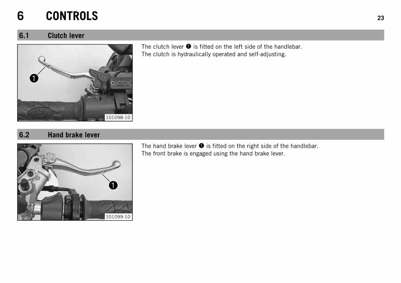
The clutch lever 1 is fitted on the left side of the handlebar.The clutch is hydraulically operated and self-adjusting.
6.2 Hand brake lever
101099-10
The hand brake lever 1 is fitted on the right side of the handlebar.The front brake is engaged using the hand brake lever.

6 CONTROLS 24
6.3 Throttle grip
101174-10
The throttle grip 1 is fitted on the right side of the handlebar.
6.4 Horn button
700550-12
The horn button 1 is fitted on the left side of the handlebar.
Possible states• Horn button in basic position• Horn button pressed – The horn is operated in this position.

6 CONTROLS 25
6.5 Light switch
700550-10
The light switch 1 is fitted on the left side of the handlebar.
Possible states
Low beam on – The light switch is turned downward. In this position, thelow beam and tail light are switched on.
High beam on – The light switch is turned upwards. In this position, thehigh beam and tail light are switched on.
6.6 Headlight flasher switch
101100-10
The headlight flasher switch 1 is fitted on the left side of the handlebar.
Possible states• Headlight flasher switch in basic position• Headlight flasher switch pressed – The headlight flasher switch (high beam) is oper-
ated in this position.
6 CONTROLS 26
6.7 Turn signal switch
700550-11
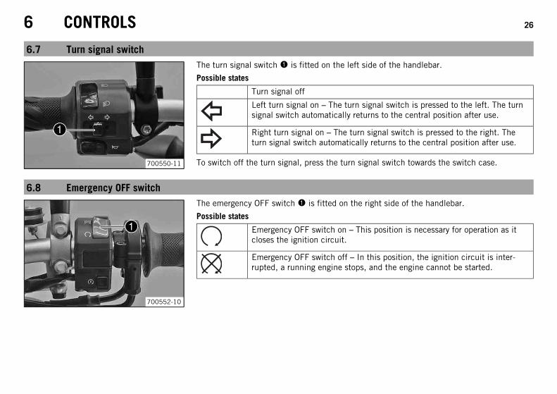
The turn signal switch 1 is fitted on the left side of the handlebar.
Possible states
Turn signal off
Left turn signal on – The turn signal switch is pressed to the left. The turnsignal switch automatically returns to the central position after use.
Right turn signal on – The turn signal switch is pressed to the right. Theturn signal switch automatically returns to the central position after use.
To switch off the turn signal, press the turn signal switch towards the switch case.
6.8 Emergency OFF switch
700552-10
The emergency OFF switch 1 is fitted on the right side of the handlebar.
Possible states
Emergency OFF switch on – This position is necessary for operation as itcloses the ignition circuit.
Emergency OFF switch off – In this position, the ignition circuit is inter-rupted, a running engine stops, and the engine cannot be started.

6 CONTROLS 27
6.9 Electric starter button
700552-11
The electric starter button 1 is fitted on the right side of the handlebar.
Possible states• Electric starter button in basic position• Electric starter button pressed – The electric starter is actuated in this position.
6.10 Ignition/steering lock
600825-01
The ignition/steering lock is in front of the upper triple clamp.
InfoThe ignition may only be switched on using a black ignition key.Use the orange programming key to activate and deactivate the black ignition key.
Possible states
Ignition OFF – In this position, the ignition circuit is interrupted, a runningengine stops, and a non-running engine will not start. The ignition key canbe removed.
Ignition ON – In this position, the ignition circuit is closed and the enginecan be started.
Steering locked – In this position, the ignition circuit is interrupted and thesteering locked. The ignition key can be removed.

6 CONTROLS 28
6.11 Immobilizer
400887-01
The electronic immobilizer secures the vehicle against unauthorized use.The immobilizer is activated automatically and the engine electronics are locked when theignition key is withdrawn.The red warning lamp flashes at 15 second intervals after one minute.The red warning lamp can also indicate errors by flashing.
InfoThe ignition key contains electronic components. Never attach multiple ignition keysto a single key ring; this may cause mutual interference and lead to problems.
A lost black ignition key must be deactivated to prevent unauthorized persons from operat-ing the vehicle.The second black ignition key is activated when the vehicle is shipped.Another two spare ignition keys (key number on the KEYCODECARD) can be ordered from anauthorized KTM workshop, but they need to be activated for use.
6.12 Combination instrument
6.12.1 Overview
400885-10
The combination instrument is installed in front of the handlebar.The combination instrument is divided into 4 function areas.1 Function buttons2 Tachometer3 Indicator lights4 Display

6 CONTROLS 29
6.12.2 Function buttons
400886-10
You can change the display mode with the MODE button 1.Possible display modes are the distance traveled (ODO), trip master 1 (TRIP 1), trip mas-ter 2 (TRIP 2) and the ambient temperature.Press the SET button 2 to reset the trip master 1 function (TRIP 1) and trip master 2 func-tion (TRIP 2) to 0.0.Button 3 has no function.
6.12.3 Tachometer
400888-10
The tachometer 1 shows the engine speed in revolutions per minute.The red marking 2 shows the excess speed range of the engine.

6 CONTROLS 30
6.12.4 indicator lamps
400889-01
The indicator lamps offer additional information about the operating state of the motorcy-cle.
Possible states
The turn signal indicator light flashes green simultaneously with the turnsignal – The turn signal is switched on.
The idling speed indicator lamp lights up green – The transmission isshifted to idle.
The high beam indicator light lights up blue – The high beam is switchedon.
The temperature warning lamp lights up red – The coolant temperature hasreached a critical value.
The low fuel warning lamp lights up yellow – The fuel level has reached thereserve mark. The display switches to TRIP F.
The oil pressure warning lamp lights up red – The oil pressure is too low.
FI warning lamp (MIL) lights up/flashes yellow – The OBD (on-board diagno-sis) has detected an emission- or safety-critical error.
The immobilizer indicator lamp lights up or flashes red – Status or errormessage for immobilizer/alarm system.
The battery warning lamp lights up red – The voltage in the vehicle systemis too low.
ABS warning lamp lights up/flashes yellow – Status or error messages relat-ing to ABS (antilock brake system).

6 CONTROLS 31
6.12.5 Display
400892-01
When you switch on the ignition, all display segments light up for one second as a functioncheck.
400881-01
LEnGthFollowing the display function check, the LEnGth wheel circumference is shown for one sec-ond.
Info1870 mm corresponds to the circumference of the 17" front wheel with a series pro-duction tire.
The display then changes to the last selected mode.

6 CONTROLS 32
6.12.6 Speed display
400838-10
The speed 1 is shown in kilometers per hour km/h or in miles per hour mph.
6.12.7 Setting kilometers or miles
InfoIf you change the unit, the value ODO is retained and converted accordingly.Making the setting according to the country.
ConditionThe motorcycle is stationary.

6 CONTROLS 33
400893-10
– Switch on the ignition by turning the ignition key to the ON position.
– Press the MODE button repeatedly until the ODO mode is active.
– Keep the MODE button pressed until the display mode changes from km/h to mph orfrom mph to km/h.
6.12.8 Time
400893-11
The time is shown in area 1 of the display.
InfoAfter reconnecting the battery or changing the fuse, the time must be reset.
6.12.9 Setting the clock
ConditionThe motorcycle is stationary.
6 CONTROLS 34
400893-12
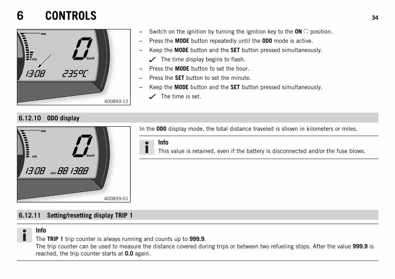
– Switch on the ignition by turning the ignition key to the ON position.
– Press the MODE button repeatedly until the ODO mode is active.
– Keep the MODE button and the SET button pressed simultaneously.
The time display begins to flash.
– Press the MODE button to set the hour.
– Press the SET button to set the minute.
– Keep the MODE button and the SET button pressed simultaneously.
The time is set.
6.12.10 ODO display
400839-01
In the ODO display mode, the total distance traveled is shown in kilometers or miles.
InfoThis value is retained, even if the battery is disconnected and/or the fuse blows.
6.12.11 Setting/resetting display TRIP 1
InfoThe TRIP 1 trip counter is always running and counts up to 999.9.The trip counter can be used to measure the distance covered during trips or between two refueling stops. After the value 999.9 isreached, the trip counter starts at 0.0 again.

6 CONTROLS 35
400840-01
– Switch on the ignition by turning the ignition key to the ON position.
– Press the MODE button repeatedly until the TRIP 1 mode is active.
– Keep the SET button pressed.
The TRIP 1 display is set to 0.0.
6.12.12 Setting/resetting display TRIP 2
InfoThe TRIP 2 trip counter is always running and counts up to 999.9.The trip counter can be used to measure the distance covered during trips or between two refueling stops. After the value 999.9 isreached, the trip counter starts at 0.0 again.
400841-01
– Switch on the ignition by turning the ignition key to the ON position.
– Press the MODE button repeatedly until the TRIP 2 mode is active.
– Keep the SET button pressed.
The TRIP 2 display is set to 0.0.

6 CONTROLS 36
6.12.13 TRIP F display
400842-01
If the fuel level drops to the reserve mark, the display automatically changes to TRIP F andstarts to count from 0.0, regardless of the previous display mode.
InfoThe low fuel warning lamp lights up in parallel to the TRIP F display.
6.12.14 Ambient temperature indicator
400893-13
The ambient temperature 1 is displayed in °C or °F.
6.12.15 Setting the temperature units
ConditionThe motorcycle is stationary.

6 CONTROLS 37
400893-14
– Switch on the ignition by turning the ignition key to the ON position.
– Press the MODE button repeatedly until the ambient temperature is active.
– Keep the MODE button pressed until the display mode changes from °C to °F or from °Fto °C.
6.12.16 Warning of icy roads
400894-10
The ice symbol lights up to indicate an increased danger of slippery roads.The ice symbol appears in the display when the ambient temperature drops below thespecified value.
Temperature 3 °C (37 °F)
The ice symbol goes out in the display when the ambient temperature rises above thespecified value again.
Temperature 4 °C (39 °F)

6 CONTROLS 38
6.12.17 Coolant temperature indicator
700124-01
The temperature display consists of 12 bars. The more bars that light up, the hotter thecoolant. When the upper bar lights up, all bars in the display begin to flash and the temper-ature warning lamp lights up.
Possible states• Engine cold – Up to five bars light up.• The engine is warm – Six to eleven bars light up.• Engine hot – All twelve bars flash.
6.13 Opening the filler cap
DangerFire hazard Fuel is highly flammable.
– Never refuel the vehicle near open flames or burning cigarettes, and always switch off the engine first. Be careful that no fuel isspilt, especially on hot vehicle components. Clean up spilt fuel immediately.
– Fuel in the fuel tank expands when warm and can escape if the tank is overfilled. See the notes on refueling.
WarningDanger of poisoning Fuel is poisonous and a health hazard.
– Avoid contact between fuel and skin, eyes and clothing. Do not inhale fuel vapors. If fuel gets into your eyes, rinse immediatelywith water and contact a doctor. Wash affected skin areas immediately with soap and water. If fuel is swallowed, contact a doc-tor immediately. Change clothing that has come into contact with fuel. Store fuel in a suitable canister according to regulationsand keep it out of the reach of children.

6 CONTROLS 39
WarningEnvironmental hazard Improper handling of fuel is a danger to the environment.
– Do not allow fuel to get into the ground water, the ground, or the sewage system.
101101-10
– Lift the cover of the filler cap 1 and insert the ignition key.
NoteDanger of damage Ignition key breakage.
– To take pressure off of the ignition key, push down on the filler cap. Damaged igni-tion keys must be replaced.
– Turn the ignition key 90° counterclockwise and remove the filler cap.
InfoThe filler cap has a tank air vent system.
6.14 Closing the filler cap
101102-01
– Put the filler cap back on and turn the ignition key 90° clockwise.
– Remove the ignition key and fold down the cover.

6 CONTROLS 40
6.15 Seat lock
101104-10
Seat lock 1 is located at the rear under the tail light.It can be locked with the ignition key.
6.16 Tool set
101571-10
The tool set 1 is located in the storage compartment under the seat.

6 CONTROLS 41
6.17 Handrails
101570-10
The handrails 1 are used for moving the motorcycle around.If you carry a passenger, the passenger can hold onto the handrails during the trip.
6.18 Helmet lock
101572-10
WarningDanger of accidents Impairment of ride behavior and vehicle operation if a helmetor helmet lock is attached to the vehicle.
– Do not use the helmet lock for holding a helmet or other objects during the jour-ney. Always remove the helmet lock before starting out.
The steel cable 1 in the tool set can be used to lock a helmet to the vehicle to prevent itfrom being stolen.

6 CONTROLS 42
6.19 Passenger footrests
101573-01
The passenger footrests can be folded up and down.
Possible states• Passenger footrests folded up – For operation without a passenger.• Passenger footrests folded down – For operation with a passenger.
6.20 Shift lever
101108-10
Shift lever 1 is mounted on the left side of the engine.

6 CONTROLS 43
101109-10
The gear positions can be seen in the photograph.The neutral or idle position N is between the first and second gear.
6.21 Foot brake lever
101110-10
Foot brake lever 1 is located in front of the right footrest.The rear brake is activated using the foot brake lever.
6 CONTROLS 44
6.22 Side stand
101111-10
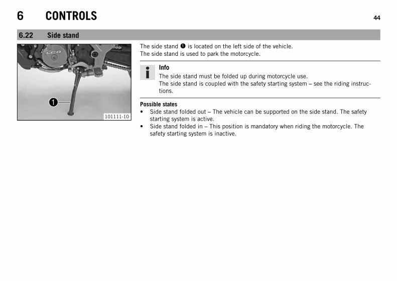
The side stand 1 is located on the left side of the vehicle.The side stand is used to park the motorcycle.
InfoThe side stand must be folded up during motorcycle use.The side stand is coupled with the safety starting system – see the riding instruc-tions.
Possible states• Side stand folded out – The vehicle can be supported on the side stand. The safety
starting system is active.• Side stand folded in – This position is mandatory when riding the motorcycle. The
safety starting system is inactive.

7 PREPARING FOR USE 45
7.1 Information on first use
DangerDanger of accidents Danger arising from the rider's judgement being impaired.
– Do not operate the vehicle while under the influence of alcohol, drugs and certain medications or physically or mentallyimpaired.
WarningRisk of injury Missing or poor protective clothing presents an increased safety risk.
– Wear protective clothing (helmet, boots, gloves, pants and jacket with protectors) every time you ride the vehicle. Always wearprotective clothing that is in good condition and meets the legal requirements.
WarningDanger of crashing Poor vehicle handling due to different tire tread patterns on front and rear wheels.
– The front and rear wheels must be fitted with tires with similar tread patterns to prevent loss of control over the vehicle.
WarningDanger of accidents Uncontrollable handling characteristic due to non-approved and/or non-recommended tires/wheels.
– Only tires/wheels approved by KTM and with the corresponding speed index should be used.
WarningDanger of accidents Reduced road grip with new tires.
– New tires have a smooth rolling surface and therefore cannot provide full road grip. The entire rolling surface must be rough-ened in the first 200 kilometers (124.3 miles) by moderate riding at alternating angles. The full grip levels are not achieveduntil the tires have been run in.
InfoWhen using your vehicle, remember that others may feel disturbed by excessive noise.
7 PREPARING FOR USE 46
– Make sure that the pre-delivery inspection work has been carried out by an authorized KTM workshop.
You receive a delivery certificate and the service record at vehicle handover.
– Before your first trip, read the entire operating instructions carefully.
– Familiarize yourself with the controls.
– Adjust the basic position of the clutch lever. ( p. 87)
– Adjust the basic position of hand brake lever. ( p. 90)
– Adjust the basic position of foot brake lever. ( p. 95)
– Get used to handling the vehicle on empty suitable terrain before making a longer trip. Try also to ride as slowly as possible to get abetter feeling for the motorcycle.
– Hold the handlebar firmly with both hands and keep your feet on the footrests when riding.
– Run the engine in. ( p. 46)
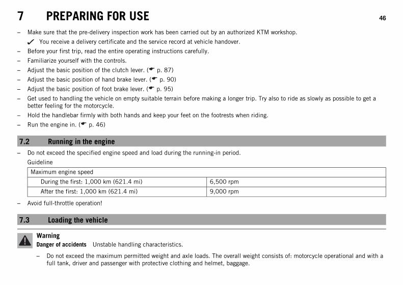
7.2 Running in the engine– Do not exceed the specified engine speed and load during the running-in period.
Guideline
Maximum engine speed
During the first: 1,000 km (621.4 mi) 6,500 rpm
After the first: 1,000 km (621.4 mi) 9,000 rpm
– Avoid full-throttle operation!
7.3 Loading the vehicle
WarningDanger of accidents Unstable handling characteristics.
– Do not exceed the maximum permitted weight and axle loads. The overall weight consists of: motorcycle operational and with afull tank, driver and passenger with protective clothing and helmet, baggage.

7 PREPARING FOR USE 47
WarningDanger of accidents Unstable handling characteristics due to incorrect mounting of suitcase and/or tank rucksack.
– Mount and secure suitcase and tank rucksack according to the manufacturer's instructions.
WarningDanger of accidents Unstable handling characteristics at high speed.
– Adapt your speed according to your payload. If the motorcycle is loaded with luggage, ride more slowly.
Maximum speed with luggage 130 km/h (80.8 mph)
WarningDanger of accidents Destruction of luggage carrier system.
– If the motorcycle is fitted with luggage cases, note the manufacturer's specifications concerning the maximum payload.
WarningDanger of accidents Poor visibility for other road users due to slipped baggage.
– If the tail light is covered, you are less visible to traffic behind you, especially in the dark. Check that your baggage is fixedproperly at regular intervals.
WarningDanger of accidents Changed handling characteristics and longer stopping distance with excessive payload.
– Adapt your speed according to your payload.
WarningDanger of accidents Unstable handling characteristics due to slipped baggage.
– Check the way your baggage is fixed regularly.
WarningDanger of burns A hot exhaust system can burn baggage.
– Fasten your baggage in such a way that it cannot be burned or singed by the hot exhaust system.

7 PREPARING FOR USE 48
– If you are carrying baggage, make sure it is fixed firmly as close as possible to the center of the vehicle and ensure even weight distri-bution between the front and rear wheels.
– Do not exceed the maximum permissible total weight and the axle loads.
Guideline
Maximum permissible total weight 400 kg (882 lb.)
Maximum permissible front axle load 160 kg (353 lb.)
Maximum permissible rear axle load 250 kg (551 lb.)
8 RIDING INSTRUCTIONS 49
8.1 Checks and maintenance measures when preparing for use
InfoBefore every trip, check the condition of the vehicle and ensure that it is roadworthy.The vehicle must be in perfect technical condition when it is being operated.
– Check the engine oil level. ( p. 157)
– Check the front brake fluid level. ( p. 91)
– Check the rear brake fluid level. ( p. 96)
– Check the front brake linings. ( p. 93)
– Check the rear brake linings. ( p. 99)
– Check that the brake system is functioning properly.
– Check the coolant level in the compensating tank. ( p. 147)
– Check the chain for dirt. ( p. 80)
– Check the chain tension. ( p. 81)
– Check the tire condition. ( p. 109)
– Check the tire air pressure. ( p. 110)
– Check that all controls are correctly adjusted and free to move.
– Check that the electrical equipment is functioning properly.
– Check that baggage is correctly secured.
– Sit on the motorcycle and check the rear mirror setting.
– Check the fuel level.
8 RIDING INSTRUCTIONS 50
8.2 Starting
DangerDanger of poisoning Exhaust gases are toxic and inhaling them may result in unconsciousness and/or death.
– When running the engine, always make sure there is sufficient ventilation, and do not start or run the engine in an enclosedspace without an effective exhaust extraction system.
CautionDanger of accidents If the vehicle is operated with a discharged battery or without a battery, electronic components and safetyequipment may be damaged.
– Never operate the vehicle with a discharged battery or without a battery.
NoteEngine failure High engine speeds in cold engines have a negative effect on the service life of the engine.
– Always warm up the engine at low engine speeds.
B00650-10
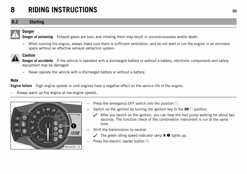
– Press the emergency OFF switch into the position .
– Switch on the ignition by turning the ignition key to the ON position.
After you switch on the ignition, you can hear the fuel pump working for about twoseconds. The function check of the combination instrument is run at the sametime.
– Shift the transmission to neutral.
The green idling speed indicator lamp N 1 lights up.
– Press the electric starter button .

8 RIDING INSTRUCTIONS 51
InfoDo not press the electric starter button until the combination instrument func-tion check is finished.When starting, DO NOT open the throttle. If you open the throttle during the start-ing procedure, fuel is not injected by the engine management system and theengine cannot start.Press the starter for a maximum of 5 seconds. Wait for a least 5 seconds beforetrying again.This motorcycle is equipped with a safety starting system. You can only start theengine if the transmission is in neutral or if the clutch is pulled when a gear isengaged. If the side stand is folded out and you shift into gear and release theclutch, the engine stops.
– Take the weight off the side stand and swing it upwards with your foot as far as it willgo.
400886-11
Switching off ABSKTM recommends riding with ABS at all times. However, situations may arise in whichABS is not advantageous.
ConditionVehicle stationary, engine running.
– Press button 2 for 3 - 5 seconds.
The ABS warning lamp starts flashing; ABS is deactivated.

8 RIDING INSTRUCTIONS 52
8.3 Starting off– Pull the clutch lever, engage 1st gear, release the clutch lever slowly and simultaneously open the throttle carefully.
8.4 Shifting, riding
WarningDanger of accidents Abrupt load alterations can cause the vehicle to get out of control.
– Avoid abrupt load alterations and sudden braking actions, and adapt your speed to the road conditions.
WarningDanger of accidents If you change down at high engine speed, the rear wheel can lock up.
– Do not change into a low gear at high engine speed. The engine races and the rear wheel can lock up.
WarningDanger of accidents Malfunctions caused by incorrect ignition key position.
– Do not change the ignition key position during a journey.
WarningDanger of accidents Distraction from traffic activity by adjustments to the vehicle.
– Make all adjustments when the vehicle is at a standstill.
WarningRisk of injury The passenger must be able to hold himself or herself properly on the passenger seat.
– The passenger must hold on to the rider or supporting strap firmly and place his/her feet on the passenger footrests. Observethe regulations concerning the minimum age for passengers in your country.
WarningDanger of accidents Danger of accidents caused by dangerous driving.
– Comply with traffic regulations and ride defensively and foresightedly to detect sources of danger early on.
8 RIDING INSTRUCTIONS 53
WarningDanger of accidents Reduced road grip with cold tires.
– On every journey, take the first miles carefully at moderate speed until the tires reach operating temperature and optimal roadgrip is ensured.
WarningDanger of accidents Reduced road grip with new tires.
– New tires have a smooth rolling surface and therefore cannot provide full road grip. The entire rolling surface must be rough-ened in the first 200 kilometers (124.3 miles) by moderate riding at alternating angles. The full grip levels are not achieveduntil the tires have been run in.
WarningDanger of accidents Unstable handling characteristics.
– Do not exceed the maximum permitted weight and axle loads. The overall weight consists of: motorcycle operational and with afull tank, driver and passenger with protective clothing and helmet, baggage.
WarningDanger of accidents Unstable handling characteristics due to slipped baggage.
– Check the way your baggage is fixed regularly.
WarningDanger of accidents Lack of roadworthiness.
– After a fall, check the vehicle as usual before preparing for use.
NoteEngine failure Unfiltered intake air has a negative effect on the service life of the engine.
– Never ride the vehicle without an air filter since dust and dirt can get into the engine and result in increased wear.

8 RIDING INSTRUCTIONS 54
NoteEngine damage Engine overheating.
– If the coolant temperature warning lamp lights up, stop the vehicle and switch off the engine. Let the engine cool, check the coolantlevel in the radiator, and correct it if necessary. If you continue riding while the coolant temperature warning lamp is lit, the enginemay be damaged.
InfoIf you hear unusual noises while riding, stop immediately, switch off the engine and contact an authorized KTM workshop.
101109-10
– When conditions allow (incline, road situation, etc.), you can shift into a higher gear.
– Release the throttle while simultaneously pulling the clutch lever, shift into the nextgear, release the clutch and open the throttle.
InfoYou can see the positions of the six forward gears in the figure. The neutral oridle position is between the first and second gears. First gear is used for startingoff or for steep inclines.
– After reaching maximum speed by fully opening the throttle grip, turn the throttle backso it is ¾ open. This will barely reduce the speed but fuel consumption will be consid-erably lower.
– Accelerate only up to a speed suitable for the road surface and weather conditions.When traveling in bends, do not shift, and accelerate very carefully.
– To shift down, brake if necessary and close the throttle at the same time.
– Pull the clutch lever and shift into a lower gear, release the clutch lever slowly and openthe throttle or shift again.
– If the engine stalls (e.g. at a crossroads), pull the clutch lever only and press the elec-tric starter button. You do not have to shift into neutral.

8 RIDING INSTRUCTIONS 55
– Switch off the engine if you expect to be standing for a long time.
– If the FI warning lamp (MIL) lights up during a trip, stop immediately. When you shift toneutral, the FI warning lamp (MIL) starts to flash.
InfoFrom the flashing rhythm, you can derive a two-digit number, the so-calledflashing code. The flashing code tells you which component has a fault.
– If the ice symbol appears on the combination instrument, roads may be icy. Adjustyour speed to the road conditions.
8.5 Braking
WarningDanger of accidents Reduced braking efficiency due to a wet or dirty brake system.
– Clean or dry a dirty or wet brake system by riding and braking gently.
WarningDanger of accidents Reduced braking efficiency caused by spongy pressure point of front or rear brake.
– Check the brake system and do not continue riding. (Your authorized KTM workshop will be glad to help.)
WarningDanger of accidents Failure of brake system.
– If the foot brake lever is not released, the brake linings drag continuously. The rear brake may fail due to overheating. Take yourfoot off the foot brake lever when you are not braking.
WarningDanger of accidents Longer stopping distance due to higher overall weight.
– Take the longer stopping distance into account when carrying a passenger and baggage.

8 RIDING INSTRUCTIONS 56
WarningDanger of accidents Delayed brake action on salted roads.
– There may be salt deposits on the brake discs. In order to restore the normal braking efficiency, you will need to remove thedeposits from the discs by carefully applying the brakes.
WarningDanger of accidents Greater stopping distance due to ABS.
– Braking should be appropriate to the driving situation and the road conditions.
WarningDanger of accidents Excessively forceful braking can cause the wheels to block.
– ABS must be switched on to be effective.
WarningDanger of accidents Locking of the wheels due to braking action of the engine.
– Pull the clutch during emergency braking, full brake application and when braking on a slippery surface.
– When braking, first throttle back and then apply the front and rear brakes at the same time.
InfoWhen ABS is active, you can achieve maximum braking power even on low grip surfaces such as sandy, wet, or slippery terrainwithout locking of the tires.
WarningDanger of accidents Road grip is reduced when braking with the motorcycle at an angle or on a laterally inclined surface.
– Braking should be completed before you enter into a bend.
– Braking should always be completed before you enter a bend. Shift down to a lower gear that is appropriate to your speed.

8 RIDING INSTRUCTIONS 57
– On long downhill stretches, use the braking effect of the engine. Do this by changing down two gears, but do not race the engine. Youwill require less braking force and the brakes will not overheat.
8.6 Stopping, parking
WarningRisk of misappropriation Usage by unauthorized persons.
– Never leave the vehicle while the engine is running. Secure the vehicle against use by unauthorized persons. If you leave thevehicle, lock the steering and remove the ignition key.
WarningDanger of burns Some vehicle components become very hot when the vehicle is operated.
– Do not touch hot components such as exhaust system, radiator, engine, shock absorber, and the brake system. Allow thesecomponents to cool down before starting work on them.
NoteDanger of damage The parked vehicle may roll away or fall over.
– Always place the vehicle on a firm and even surface.
NoteFire hazard Some vehicle components become very hot when the vehicle is operated.
– Do not park the vehicle near flammable or explosive substances. Do not place objects on the vehicle while it is still warm from beingrun. Always let the vehicle cool first.
NoteMaterial damage Damage and destruction of components by excessive load.
– The side stand is designed for the weight of the motorcycle only. Do not sit on the motorcycle when it is supported by the side standonly. The side stand and/or the frame could be damaged and the motorcycle could fall over.
8 RIDING INSTRUCTIONS 58
– Apply the brakes.
– Shift the transmission to neutral.
– Switch off the ignition by turning the ignition key to the OFF position.
InfoIf you switch off the engine with the emergency OFF switch but the ignition remains switched on at the ignition lock, powercontinues to flow to most power consumers and the battery is soon discharged. Therefore, always switch off the engine with theignition key; the emergency OFF switch is provided for emergency situations only.
– Park the motorcycle on a firm surface.
– Swing the side stand to the front with your foot as far as it will go, and lean the vehicle onto it.
– Lock the steering by turning the handlebar fully to the left, pressing down the ignition key to the OFF position and turning it tothe position . To make the steering lock engage more easily, move the handlebar back and forth slightly. Remove the ignition key.
8.7 Transport
NoteDanger of damage The parked vehicle may roll away or fall over.
– Always place the vehicle on a firm and even surface.
NoteFire hazard Some vehicle components become very hot when the vehicle is operated.
– Do not park the vehicle near flammable or explosive substances. Do not place objects on the vehicle while it is still warm from beingrun. Always let the vehicle cool first.

8 RIDING INSTRUCTIONS 59
401448-01
– Switch off the engine and remove the ignition key.
– Use tension belts or other suitable devices to secure the motorcycle against accidentsor falling over.
8.8 Refueling
DangerFire hazard Fuel is highly flammable.
– Never refuel the vehicle near open flames or burning cigarettes, and always switch off the engine first. Be careful that no fuel isspilt, especially on hot vehicle components. Clean up spilt fuel immediately.
– Fuel in the fuel tank expands when warm and can escape if the tank is overfilled. See the notes on refueling.
WarningDanger of poisoning Fuel is poisonous and a health hazard.
– Avoid contact of the fuel with skin, eyes and clothing. Do not inhale fuel vapors. If fuel gets into your eyes, rinse immediatelywith water and contact a doctor. Wash affected skin areas immediately with soap and water. If fuel is swallowed, contact a doc-tor immediately. Change clothing that has come into contact with fuel.
NoteMaterial damage Premature clogging of the fuel filter.
– In some countries and regions, the available fuel quality and cleanliness may not be sufficient. This will result in problems with thefuel system. (Your authorized KTM workshop will be glad to help.)

8 RIDING INSTRUCTIONS 60
– Only refuel with clean fuel that meets the specified standards.
WarningEnvironmental hazard Improper handling of fuel is a danger to the environment.
– Do not allow fuel to get into the ground water, the ground, or the sewage system.
401182-10
– Switch off the engine.
– Open the filler cap. ( p. 38)
– Fill the fuel tank with fuel no higher than level A.
Guideline
Distance A 35 mm (1.38 in)
Total fuel tankcapacity, approx.
15 l (4 US gal) Super unleaded (ROZ 95/RON 95/PON91) ( p. 199)
– Close the filler cap. ( p. 39)
400885-12
– Press the SET button 2 for two seconds.
The low fuel warning lamp 1 goes out. TRIP F is set to 0.0 and the display returnsto the previous display mode.
InfoIf you do not press the SET button 2, the reset takes place automatically afterapprox. three minutes.

9 SERVICE SCHEDULE 61
9.1 Service schedule
K10N K75A K150A K300A
Check that the electrical equipment is functioning properly. • • • •
Read out the trouble code memory using the KTM diagnostics tool.x • • • •
Check the measured service values with the KTM diagnostics tool.x • • •
Change the engine oil and filter, clean the oil screens.x ( p. 158) • • • •
Check the oil jet for the clutch lubrication.x • • •
Check the front brake linings. ( p. 93) • • • •
Check the front brake discs. ( p. 90) • • • •
Check the rear brake linings. ( p. 99) • • • •
Check the rear brake disc. ( p. 96) • • • •
Check that brake lines are undamaged and free of leaks. • • • •
Check the rear brake fluid level. ( p. 96) • • • •
Check the free travel of the foot brake lever. ( p. 94) • • • •
Check the shock absorber and fork for leaks. Perform a fork and shock absorber service if neededand depending on vehicle use.
• • • •
Check the swingarm bearings.x • • •
Check the wheel bearing for play.x • • •
Check the tire condition. ( p. 109) • • • •
Check the tire air pressure. ( p. 110) • • • •
Check the chain, rear sprocket, engine sprocket, and chain guide. ( p. 84) • • •
Check the chain tension. ( p. 81) • • • •
Lubricate all moving parts (e.g. side stand, hand lever, chain, ...) and check for smooth opera-tion.x • • • •

9 SERVICE SCHEDULE 62
K10N K75A K150A K300A
Clean the dust boots of the fork legs. • • •
Check the front brake fluid level. ( p. 91) • • • •
Bleed the fork legs. ( p. 75) • • •
Check the steering head bearing play. • • • •
Change the spark plugs.x • •
Check the valve clearance.x • •
Check all hoses (e.g. fuel, cooling, bleeding, drainage, ...) and sleeves for cracking, leaks, andincorrect routing.x • •
Check the antifreeze and coolant level. ( p. 144) • • • •
Check the wiring harness of the throttle valve body for damage and correct routing.x • •
Check the cables for damage and kink-free routing.x • •
Check the control cables for damage, kink-free routing and adjustment. • • • •
Change the air filter. Clean the air filter box.x • •
Check the fuel pressure.x • • •
Check the value of the manifold absolute pressure sensor (PM value) with the KTM diagnosticstool.x • • •
Check the CO adjustment with the KTM diagnostics tool.x • • •
Check/rectify the fluid level of the hydraulic clutch. ( p. 87) • • •
Check the fasteners for tightness.x • • • •
Change the coolant.x •
Change the front brake fluid.x • •
Change the rear brake fluid.x • •
Check the clutch.x • •
9 SERVICE SCHEDULE 63
K10N K75A K150A K300A
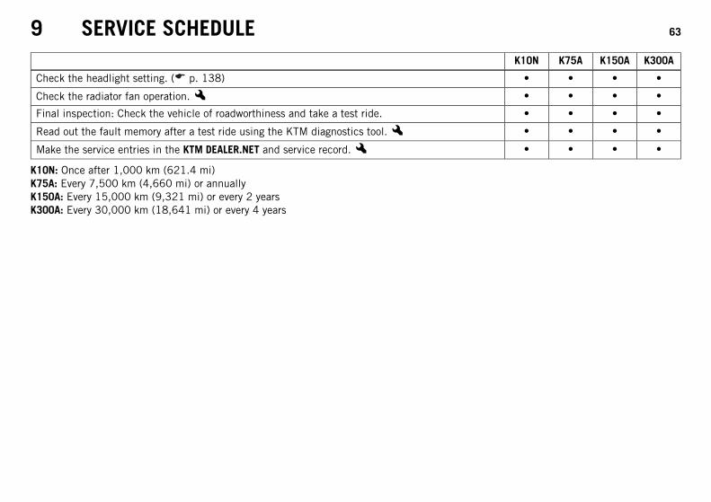
Check the headlight setting. ( p. 138) • • • •
Check the radiator fan operation.x • • • •
Final inspection: Check the vehicle of roadworthiness and take a test ride. • • • •
Read out the fault memory after a test ride using the KTM diagnostics tool.x • • • •
Make the service entries in the KTM DEALER.NET and service record.x • • • •
K10N: Once after 1,000 km (621.4 mi)K75A: Every 7,500 km (4,660 mi) or annuallyK150A: Every 15,000 km (9,321 mi) or every 2 yearsK300A: Every 30,000 km (18,641 mi) or every 4 years
10 TUNING THE CHASSIS 64
10.1 Fork/shock absorber
101114-10
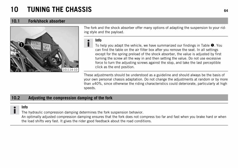
The fork and the shock absorber offer many options of adapting the suspension to your rid-ing style and the payload.
InfoTo help you adapt the vehicle, we have summarized our findings in Table 1. Youcan find the table on the air filter box after you remove the seat. In all settingsexcept for the spring preload of the shock absorber, the value is adjusted by firstturning the screw all the way in and then setting the value. Do not use excessiveforce to turn the adjusting screws against the stop, and take the last perceptibleclick as the end position.
These adjustments should be understood as a guideline and should always be the basis ofyour own personal chassis adaptation. Do not change the adjustments at random or by morethan ±40%, since otherwise the riding characteristics could deteriorate, particularly at highspeeds.
10.2 Adjusting the compression damping of the fork
InfoThe hydraulic compression damping determines the fork suspension behavior.An optimally adjusted compression damping ensures that the fork does not compress too far and fast when you brake hard or whenthe load shifts very fast. It gives the rider good feedback about the road conditions.

10 TUNING THE CHASSIS 65
101574-10
– Turn adjusting screws 1 clockwise all the way.
InfoThe adjusting screws are located at the bottom end of the fork legs.Make the same adjustment on both fork legs.
– Turn back counterclockwise by the number of clicks corresponding to the fork type.
Guideline
Compression damping
Comfort 20 clicks
Standard 15 clicks
Sport 10 clicks
Full payload 10 clicks
InfoTurn clockwise to increase damping; turn counterclockwise to reduce damping.
10.3 Adjusting the rebound damping of the fork
InfoThe hydraulic rebound damping determines the fork rebound behavior.An optimally adjusted rebound damping brakes the springing energy and enables a fast, vibration-free resetting of the fork to thezero position.

10 TUNING THE CHASSIS 66
101116-10
– Turn adjusting screws 1 clockwise all the way.
InfoThe adjusting screws are located at the top end of the fork legs.Make the same adjustment on both fork legs.
– Turn back counterclockwise by the number of clicks corresponding to the fork type.
Guideline
Rebound damping
Comfort 20 clicks
Standard 15 clicks
Sport 10 clicks
Full payload 10 clicks
InfoTurn clockwise to increase damping; turn counterclockwise to reduce damping.
10.4 Adjusting the spring preload of the fork
InfoThe spring preload determines the initial fork position.The best spring preload setting is achieved when it is set for the weight of the rider and that of any baggage and a passenger, thusensuring an ideal compromise between maneuverability and stability.

10 TUNING THE CHASSIS 67
101117-10
– Turn adjusting screws 1 clockwise all the way.
InfoThe adjusting screws are located at the top end of the fork legs.Make the same adjustment on both fork legs.
– Turn back counterclockwise by the number of turns according to the fork type.
Guideline
Spring preload - Preload Adjuster
Comfort 5 turns
Standard 5 turns
Sport 7 turns
Full payload 7 turns
InfoTurn clockwise to increase preload; turn counterclockwise to reduce springpreload.Changing the spring preload has no influence on the rebound damping althoughthe adjusting screws turn during the adjustment work. However, you should alsoadjust the rebound damping when you alter the spring preload.

10 TUNING THE CHASSIS 68
10.5 Compression damping of the shock absorber
101119-01
The compression damping of the shock absorber is divided into two ranges: high-speed andlow-speed.High-speed and low-speed refer to the compression speed of the rear wheel suspension andnot to the vehicle speed.The high-speed setting, for example, has an effect on the landing after a jump: the rearwheel suspension compresses more quickly.The low-speed setting, for example, has an effect when riding over long ground swells: therear wheel suspension compresses more slowly.These two ranges can be adjusted separately, although the transition between high-speedand low-speed is gradual. Thus, changes in the high-speed range affect the compressiondamping in the low-speed range and vice versa.
10.6 Adjusting the low-speed compression damping of the shock absorber
CautionDanger of accidents Disassembly of pressurized parts can lead to injury.
– The shock absorber is filled with high density nitrogen. Adhere to the description provided. (Your authorized KTM workshop willbe glad to help.)
InfoThe low-speed setting can be seen during the slow to normal compression of the shock absorber.

10 TUNING THE CHASSIS 69
101120-10
– Turn adjusting screw 1 clockwise with a screwdriver up to the last perceptible click.
InfoDo not loosen nut 2!
– Turn back counterclockwise by the number of clicks corresponding to the shockabsorber type.
Guideline
Compression damping, low-speed
Comfort 25 clicks
Standard 20 clicks
Sport 15 clicks
Full payload 15 clicks
InfoTurn clockwise to increase damping; turn counterclockwise to reduce damping.
10.7 Adjusting the high-speed compression damping of the shock absorber
CautionDanger of accidents Disassembly of pressurized parts can lead to injury.
– The shock absorber is filled with high density nitrogen. Adhere to the description provided. (Your authorized KTM workshop willbe glad to help.)
InfoThe high-speed setting can be seen during the fast compression of the shock absorber.

10 TUNING THE CHASSIS 70
101120-11
– Turn adjusting screw 1 clockwise all the way using a socket wrench.
InfoDo not loosen nut 2!
– Turn back counterclockwise by the number of turns corresponding to the shockabsorber type.
Guideline
Compression damping, high-speed
Comfort 2 turns
Standard 1.5 turns
Sport 1 turn
Full payload 1 turn
InfoTurn clockwise to increase damping; turn counterclockwise to reduce damping.
10.8 Adjusting the rebound damping of the shock absorber
CautionDanger of accidents Disassembly of pressurized parts can lead to injury.
– The shock absorber is filled with high density nitrogen. Adhere to the description provided. (Your authorized KTM workshop willbe glad to help.)

10 TUNING THE CHASSIS 71
101575-10
– Turn adjusting screw 1 clockwise up to the last perceptible click.
– Turn back counterclockwise by the number of clicks corresponding to the shockabsorber type.
Guideline
Rebound damping
Comfort 20 clicks
Standard 15 clicks
Sport 10 clicks
Full payload 10 clicks
InfoTurn clockwise to increase damping; turn counterclockwise to reduce damping.
10.9 Adjusting the spring preload of the shock absorberx
WarningDanger of accidents Modifications to the suspension settings can seriously alter the vehicle's ride behavior.
– Following modifications, ride slowly at first to get the feel of the new ride behavior.
InfoThe spring preload defines the initial situation of the spring process on the shock absorber.The best spring preload setting is achieved when it is set for the weight of the rider and that of any baggage and a passenger, thusensuring an ideal compromise between maneuverability and stability.Before changing the spring preload, make a note of the present setting, e.g., by measuring the length of the spring.

10 TUNING THE CHASSIS 72
Preparatory work– Take the weight off the rear wheel and swingarm.
InfoThe spring preload can be adjusted correctly only if the rear wheel and theswingarm are fully relieved of weight.
101122-10
Main work– Release retaining ring 1.
– Turn adjusting ring 2 until the spring is fully relaxed.
Hook wrench (T157S)
– Measure the overall spring length without a load.
– Tension the spring by turning adjusting ring 2 to the prescribed value.
Guideline
Spring preload
Comfort 11 mm (0.43 in)
Standard 11 mm (0.43 in)
Sport 11 mm (0.43 in)
Full payload 13 mm (0.51 in)
– Tighten retaining ring 1.

11 SERVICE WORK ON THE CHASSIS 73
11.1 Raising the motorcycle with the rear wheel stand
NoteDanger of damage The parked vehicle may roll away or fall over.
– Always place the vehicle on a firm and even surface.
101577-01
– Mount the lifting bushings on the swingarm.
– Insert the adapter in the rear wheel stand.
Adapter (61029055120)
Rear wheel stand (61029055400)
– Stand the motorcycle upright, align the wheel stand with the swingarm and theadapters, and lift the motorcycle.
11.2 Taking the motorcycle off of the rear wheel stand
NoteDanger of damage The parked vehicle may roll away or fall over.
– Always place the vehicle on a firm and even surface.
– Secure the motorcycle against falling over.
– Remove the rear wheel stand and lean the vehicle on the side stand.
– Remove the lifting bushings from the swingarm.

11 SERVICE WORK ON THE CHASSIS 74
11.3 Raising the motorcycle with the front wheel stand
NoteDanger of damage The parked vehicle may roll away or fall over.
– Always place the vehicle on a firm and even surface.
Preparatory work– Raise the motorcycle with the rear wheel stand. ( p. 73)
101576-01
Main work– Move the handlebar to the straight-ahead position. Align the front wheel stand with the
fork legs using the adapters.
Front wheel stand (61029055300)
InfoAlways raise the rear of the motorcycle first.
– Raise the front of the motorcycle.
11.4 Taking the motorcycle off of the front wheel stand
NoteDanger of damage The parked vehicle may roll away or fall over.
– Always place the vehicle on a firm and even surface.
– Secure the motorcycle against falling over.
– Remove the front wheel stand.

11 SERVICE WORK ON THE CHASSIS 75
11.5 Bleeding the fork legsPreparatory work– Lean the motorcycle on the side stand.
101118-10
Main work– Remove bleeder screws 1 briefly.
Any excess pressure escapes from the interior of the fork.
– Mount and tighten the bleeder screws.
InfoCarry out this operation on both fork legs.
11.6 Removing the seat
101104-10
– Insert the ignition key in the seat lock 1 and turn it clockwise.
– Raise the rear of the seat, push it towards the rear, and remove it upwards.
– Remove the ignition key from the seat lock.

11 SERVICE WORK ON THE CHASSIS 76
11.7 Mounting the seat
101578-10
– Position front recesses 1 of the seat on the oval head screws of the fuel tank, lowerthe rear and simultaneously push it forward. Both lugs 2 must hook into the frame andlocking bolt 3 must be inserted into the lock housing.
The seat engages with an audible click.
– Finally, check that the seat is correctly mounted.
11.8 Reinstalling the fuel tankPreparatory work– Remove the seat. ( p. 75)
101163-10
Main work– Remove screws 1 and the spoiler on both sides.
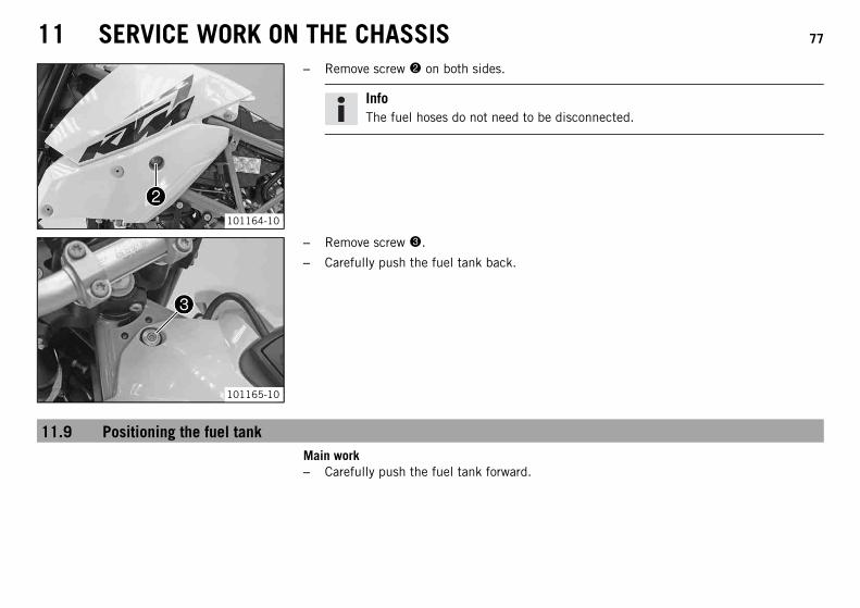
11 SERVICE WORK ON THE CHASSIS 77
101164-10
– Remove screw 2 on both sides.
InfoThe fuel hoses do not need to be disconnected.
101165-10
– Remove screw 3.
– Carefully push the fuel tank back.
11.9 Positioning the fuel tankMain work– Carefully push the fuel tank forward.

11 SERVICE WORK ON THE CHASSIS 78
101165-11
– Mount and tighten screw 1 with the collar bushing.
Guideline
Remaining chassis screws M6 10 Nm (7.4 lbf ft)
101164-10
– Install and tighten screw 2 with the bearing sleeve and rubber bushing on both sides.
Guideline
Remaining chassis screws M8 25 Nm(18.4 lbf ft)
– Check the routing of the fuel lines.
101163-11
– Position the spoilers on both sides. Mount and tighten screws 3.
Guideline
Screw, spoiler M6 3.3 Nm(2.43 lbf ft)

11 SERVICE WORK ON THE CHASSIS 79
Finishing work– Mount the seat. ( p. 76)
11.10 Mounting the helmet lock on the vehicle
WarningDanger of accidents Impairment of ride behavior and vehicle operation if a helmet or helmet lock is attached to the vehicle.
– Do not use the helmet lock for holding a helmet or other objects during the journey. Always remove the helmet lock before start-ing out.
Preparatory work– Remove the seat. ( p. 75)
101579-10
Main work– Position the steel cable from the tool set with one loop on hook 1.
Steel cable (60012015000)
– Guide the steel cable through the helmet opening.
– Attach the free loop of the steel cable to the hook as well.
– Position the helmet carefully on the side of the vehicle.
Finishing work– Mount the seat. ( p. 76)

11 SERVICE WORK ON THE CHASSIS 80
11.11 Checking the chain for dirt
400678-01
– Check the chain for coarse dirt accumulation.
» If the chain is very dirty:
– Clean the chain. ( p. 80)
11.12 Cleaning the chain
WarningDanger of accidents Oil or grease on the tires reduces their grip.
– Remove oil and grease with a suitable cleaning material.
WarningDanger of accidents Reduced braking efficiency due to oil or grease on the brake discs.
– Always keep the brake discs free of oil and grease, and clean them with brake cleaner when necessary.
WarningEnvironmental hazard Hazardous substances cause environmental damage.
– Oil, grease, filters, fuel, cleaners, brake fluid, etc., should be disposed of as stipulated in applicable regulations.
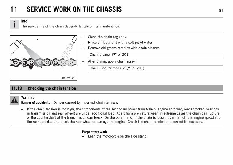
11 SERVICE WORK ON THE CHASSIS 81
InfoThe service life of the chain depends largely on its maintenance.
400725-01
– Clean the chain regularly.
– Rinse off loose dirt with a soft jet of water.
– Remove old grease remains with chain cleaner.
Chain cleaner ( p. 201)
– After drying, apply chain spray.
Chain lube for road use ( p. 201)
11.13 Checking the chain tension
WarningDanger of accidents Danger caused by incorrect chain tension.
– If the chain tension is too high, the components of the secondary power train (chain, engine sprocket, rear sprocket, bearingsin transmission and rear wheel) are under additional load. Apart from premature wear, in extreme cases the chain can ruptureor the countershaft of the transmission can break. On the other hand, if the chain is loose, it can fall off the engine sprocket orthe rear sprocket and block the rear wheel or damage the engine. Check the chain tension and correct if necessary.
Preparatory work– Lean the motorcycle on the side stand.

11 SERVICE WORK ON THE CHASSIS 82
700570-01
Main work– Shift the transmission to neutral.
– In the area of chain sliding guard, press the chain upward toward the swingarm anddetermine chain tension A.
InfoThe upper chain section B must be taut.Chain wear is not always even, so you should repeat this measurement at differ-ent chain positions.
Chain tension 7 mm (0.28 in)
» If the chain tension does not meet specifications:
– Adjust the chain tension. ( p. 82)
11.14 Adjusting the chain tension
WarningDanger of accidents Danger caused by incorrect chain tension.
– If the chain tension is too high, the components of the secondary power train (chain, engine sprocket, rear sprocket, bearingsin transmission and rear wheel) are under additional load. Apart from premature wear, in extreme cases the chain can ruptureor the countershaft of the transmission can break. On the other hand, if the chain is loose, it can fall off the engine sprocket orthe rear sprocket and block the rear wheel or damage the engine. Check the chain tension and correct if necessary.
Preparatory work– Lean the motorcycle on the side stand.
– Check the chain tension. ( p. 81)
– Remove the frame slider.

11 SERVICE WORK ON THE CHASSIS 83
101581-10
Main work– Loosen nut 1.
– Loosen nuts 2.
– Adjust the chain tension by turning the adjusting screws 3 on the left and right.
Guideline
Chain tension 7 mm (0.28 in)
Turn adjusting screws 3 on the left and right so that the markings on the left andright chain adjuster 4 are in the same position in relation to reference marks C. Therear wheel is then correctly aligned.
InfoThe upper chain section must be taut.Chain wear is not always even, so you should check the setting at different chainpositions.
– Tighten nuts 2.
– Make sure that chain adjusters 4 are resting against adjusting screws 3.
– Tighten nut 1.
Guideline
Nut, rear wheel spindle M25x1.5 90 Nm(66.4 lbf ft)
Thread greased
InfoThe wide adjustment range of the chain adjusters (32 mm (1.26 in)) enablesdifferent secondary transmissions with the same chain length.Chain adjusters 4 can be turned through 180°.

11 SERVICE WORK ON THE CHASSIS 84
11.15 Checking the chain, rear sprocket, engine sprocket and chain guide
100132-10
– Check the rear sprocket and engine sprocket for wear.
» If the rear sprocket or engine sprocket is worn:
– Change the power set.x
InfoThe rear sprocket, engine sprocket and chain should always be changedtogether.
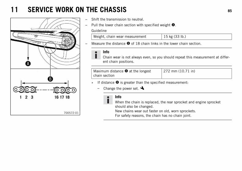
11 SERVICE WORK ON THE CHASSIS 85
700572-01
– Shift the transmission to neutral.
– Pull the lower chain section with specified weight A.
Guideline
Weight, chain wear measurement 15 kg (33 lb.)
– Measure the distance B of 18 chain links in the lower chain section.
InfoChain wear is not always even, so you should repeat this measurement at differ-ent chain positions.
Maximum distance B at the longestchain section
272 mm (10.71 in)
» If distance B is greater than the specified measurement:
– Change the power set.x
InfoWhen the chain is replaced, the rear sprocket and engine sprocketshould also be changed.New chains wear out faster on old, worn sprockets.For safety reasons, the chain has no chain joint.

11 SERVICE WORK ON THE CHASSIS 86
101582-10
– Check the chain sliding guard for wear.
» If there is no gap between the chain and the upper edge of the screw:
– Change the chain sliding guard.x– Check the chain sliding guard for tightness.
» If the chain sliding guard is loose:
– Tighten the chain sliding guard.
Guideline
Screw, chain slidingguard
M5 5 Nm(3.7 lbf ft)
–
Screw, chain slidingguard
M6 6 Nm(4.4 lbf ft)
Loctite® 243™
101583-10
– Check the chain sliding piece for wear.
» If the drill hole becomes visible on the chain sliding piece in area C:
– Change the chain sliding piece.x– Check the chain sliding piece for tightness.
» If the chain sliding piece is loose:
– Tighten the chain sliding piece.
Guideline
Screw, chain sliding piece EJOT PT K60x20 2 Nm (1.5 lbf ft)

11 SERVICE WORK ON THE CHASSIS 87
11.16 Adjusting the basic position of the clutch lever
InfoTurn the adjusting screw clockwise to increase the distance between the clutch lever and the handlebar.Turn the adjusting screw counterclockwise to decrease the distance between the clutch lever and the handlebar.The range of adjustment is limited.Turn the adjusting screw by hand only, and do not apply any force.Do not make any adjustments while riding!
101166-10
– Adjust the basic setting of the clutch lever to your hand size by turning adjustingscrew 1.
11.17 Checking/rectifying the fluid level of the hydraulic clutch
InfoThe fluid level rises with increasing wear of the clutch lining disc.Do not use brake fluid.
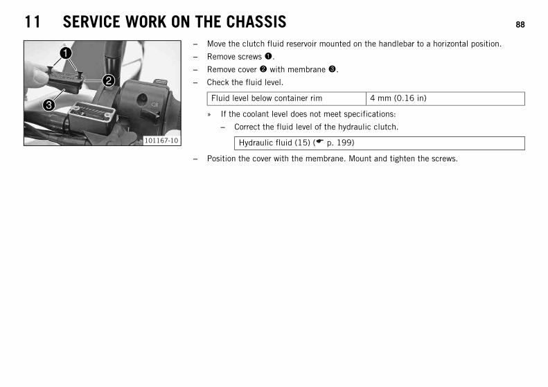
11 SERVICE WORK ON THE CHASSIS 88
101167-10
– Move the clutch fluid reservoir mounted on the handlebar to a horizontal position.
– Remove screws 1.
– Remove cover 2 with membrane 3.
– Check the fluid level.
Fluid level below container rim 4 mm (0.16 in)
» If the coolant level does not meet specifications:
– Correct the fluid level of the hydraulic clutch.
Hydraulic fluid (15) ( p. 199)
– Position the cover with the membrane. Mount and tighten the screws.

12 BRAKE SYSTEM 89
12.1 ABS/antilock brake system
00440033 0022
0022
0011
401410-10
The ABS unit 1, which consists of a hydraulic unit, ABS control unit, and return pump, isinstalled under the seat. The front and rear wheels each have a wheel speed sensor 2.
WarningDanger of accidents Functional limitations of the ABS
– The rear wheel may only be spun with the front brake applied (burn out) if theABS is switched off.
– If the vehicle has been modified, such as shortened or lengthened spring deflec-tions, different rim diameters, different tires, the wrong tire air pressure, differ-ent brake linings, etc., the ABS will not function optimally. Optimal function-ing of the ABS is only ensured if the brake system only contains spare parts andtires that have been approved and/or recommended by KTM.
– Service work and repairs must be performed properly. (Your authorized KTMworkshop will be glad to help.)
The ABS is a safety system that prevents locking of the wheels when the vehicle is travelingstraight ahead without the action of lateral forces.
WarningDanger of accidents Rolling over of the vehicle
– It is not always possible to prevent rolling over of the vehicle in extreme ridingsituations (e. g. luggage loaded with a high center of gravity, varying road sur-faces, steep descents, full braking without disengaging the gear). Adapt yourriding style to the road conditions and your riding ability.
The ABS operates with two independent brake circuits (front and rear brakes). During nor-mal operation, the brake system operates like a conventional brake system without ABS.When the ABS control unit detects the tendency of a wheel to lock, the ABS begins regu-lating the braking pressure. The control process causes the hand and foot brake levers tovibrate slightly.

12 BRAKE SYSTEM 90
The ABS warning lamp 3 must light up briefly after the ignition is switched on and shouldthen goes out after starting off. If it does not go out after starting off or if it lights up whileriding, this indicates a fault in the ABS system. In this case, the ABS is no longer enabledand the wheels may lock during braking. The brake system itself stays functional; only ABScontrol is not available.The ABS warning lamp may also light up if the rotating speeds of the front and rear wheelsdiffer greatly under extreme riding conditions, for example when making wheelies or if therear wheel spins. This causes the ABS to switch off.To reenable the ABS, the vehicle must be stopped and the ignition switched off. The ABSis reenabled when the vehicle is switched on again. The ABS warning lamp goes out whenyou start off.Button 4 can be used to switch ABS off manually (see Starting).
12.2 Adjusting the basic position of the hand brake lever
101124-10
– Pull the hand brake lever forward.
– Adjust the basic setting of the hand brake lever to your hand size by turning adjustingwheel 1.
InfoDo not make any adjustments while riding!
12.3 Checking the front brake discs
WarningDanger of accidents Reduced braking efficiency due to worn brake disc(s).
– Change the worn brake disc(s) without delay. (Your authorized KTM workshop will be glad to help.)

12 BRAKE SYSTEM 91
100135-10
– Check the thickness of the brake disc in several places to see if it conforms to measure-ment A.
InfoWear reduces the thickness of the brake discs in area 1 of the brake discs.
Brake discs - wear limit
Front 4.5 mm (0.177 in)
» If the brake disc thickness is less than the specified value:
– Change the brake discs.x– Check the brake discs for damage, cracking and deformation.
» If the brake discs exhibit damage, cracking or deformation:
– Change the brake discs.x
12.4 Checking the front brake fluid level
WarningDanger of accidents Failure of the brake system.
– If the brake fluid level falls below the MIN mark, this indicates a leakage in the brake system or worn-out brake linings. Checkthe brake system and do not continue riding. (Your authorized KTM workshop will be glad to help.)
WarningDanger of accidents Reduced braking efficiency due to old brake fluid.
– Change the brake fluid of the front and rear brake according to the service schedule. (Your authorized KTM workshop will beglad to help.)
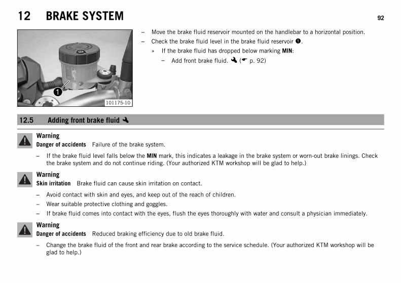
12 BRAKE SYSTEM 92
101175-10
– Move the brake fluid reservoir mounted on the handlebar to a horizontal position.
– Check the brake fluid level in the brake fluid reservoir 1.
» If the brake fluid has dropped below marking MIN:
– Add front brake fluid.x ( p. 92)
12.5 Adding front brake fluidx
WarningDanger of accidents Failure of the brake system.
– If the brake fluid level falls below the MIN mark, this indicates a leakage in the brake system or worn-out brake linings. Checkthe brake system and do not continue riding. (Your authorized KTM workshop will be glad to help.)
WarningSkin irritation Brake fluid can cause skin irritation on contact.
– Avoid contact with skin and eyes, and keep out of the reach of children.
– Wear suitable protective clothing and goggles.
– If brake fluid comes into contact with the eyes, flush the eyes thoroughly with water and consult a physician immediately.
WarningDanger of accidents Reduced braking efficiency due to old brake fluid.
– Change the brake fluid of the front and rear brake according to the service schedule. (Your authorized KTM workshop will beglad to help.)

12 BRAKE SYSTEM 93
WarningEnvironmental hazard Hazardous substances cause environmental damage.
– Oil, grease, filters, fuel, cleaners, brake fluid, etc., should be disposed of as stipulated in applicable regulations.
InfoAvoid contact between brake fluid and painted parts. Brake fluid is corrosive and will damage painted surfaces.Use only clean brake fluid from a sealed container.
101176-10
– Move the brake fluid reservoir mounted on the handlebar to a horizontal position.
– Remove screws.
– Remove cover 1 with membrane 2.
– Add brake fluid to the MAX mark.
Brake fluid DOT 4 / DOT 5.1 ( p. 197)
– Position the cover with the membrane. Mount and tighten the screws.
InfoClean up overflowed or spilt brake fluid immediately with water.
12.6 Checking the front brake linings
WarningDanger of accidents Reduced braking efficiency caused by worn brake linings.
– Change worn brake linings immediately. (Your authorized KTM workshop will be glad to help.)

12 BRAKE SYSTEM 94
NoteDanger of accidents Reduced braking efficiency caused by damaged brake discs.
– If the brake linings are not changed in time, the steel brake lining carriers grind on the brake disc. The braking effect is greatlyreduced and the brake discs are destroyed. Check the brake linings regularly.
101584-10
– Check all brake linings on both brake calipers to ensure they have minimum thick-ness A.
Minimum thickness A ≥ 1 mm (≥ 0.04 in)
» If the minimum thickness is less than specified:
– Change the front brake linings.x– Check all brake linings on both brake calipers for damage and cracking.
» If damage or wear is encountered:
– Change the front brake linings.x
12.7 Checking the free travel of the foot brake lever
WarningDanger of accidents Brake system failure.
– If there is no free travel on the foot brake lever, pressure builds up on the rear brake circuit. The rear brake can fail due to over-heating. Adjust the free travel on foot brake lever according to specifications.

12 BRAKE SYSTEM 95
101125-10
– Move the foot brake lever back and forth between the end stop and the contact to thepiston rod and check free travel A.
Guideline
Free travel at foot brake lever 3… 5 mm (0.12… 0.2 in)
InfoThe piston rod should not move.
» If the free travel does not meet specifications:
– Adjust the free travel to the specified value.
12.8 Adjusting the basic position of the foot brake lever
WarningDanger of accidents Brake system failure.
– If there is no free travel on the foot brake lever, pressure builds up on the rear brake circuit. The rear brake can fail due to over-heating. Adjust the free travel on foot brake lever according to specifications.
101585-10
– Release nut 1 and turn push rod 2 until the foot brake lever is in the desired position.
At least two thread turns are visible at the lower nut.
InfoThe range of adjustment is limited.
– Check the free travel of the foot brake lever. ( p. 94)
– Tighten nut 1.
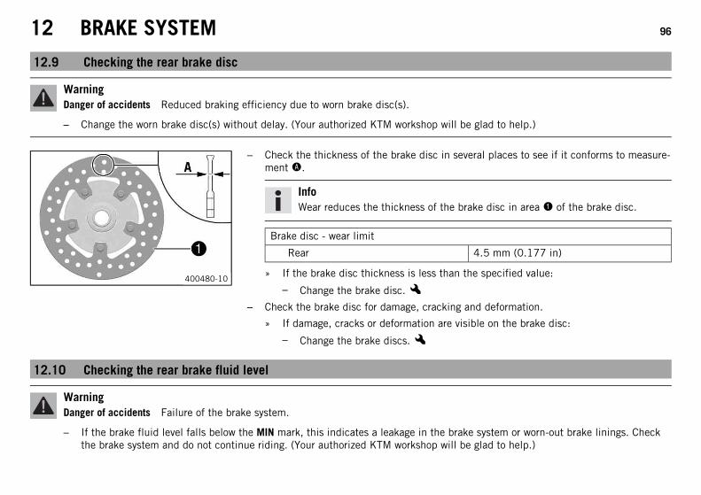
12 BRAKE SYSTEM 96
12.9 Checking the rear brake disc
WarningDanger of accidents Reduced braking efficiency due to worn brake disc(s).
– Change the worn brake disc(s) without delay. (Your authorized KTM workshop will be glad to help.)
400480-10
– Check the thickness of the brake disc in several places to see if it conforms to measure-ment A.
InfoWear reduces the thickness of the brake disc in area 1 of the brake disc.
Brake disc - wear limit
Rear 4.5 mm (0.177 in)
» If the brake disc thickness is less than the specified value:
– Change the brake disc.x– Check the brake disc for damage, cracking and deformation.
» If damage, cracks or deformation are visible on the brake disc:
– Change the brake discs.x
12.10 Checking the rear brake fluid level
WarningDanger of accidents Failure of the brake system.
– If the brake fluid level falls below the MIN mark, this indicates a leakage in the brake system or worn-out brake linings. Checkthe brake system and do not continue riding. (Your authorized KTM workshop will be glad to help.)
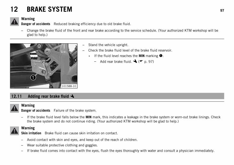
12 BRAKE SYSTEM 97
WarningDanger of accidents Reduced braking efficiency due to old brake fluid.
– Change the brake fluid of the front and rear brake according to the service schedule. (Your authorized KTM workshop will beglad to help.)
101588-10
– Stand the vehicle upright.
– Check the brake fluid level of the brake fluid reservoir.
» If the fluid level reaches the MIN marking 1:
– Add rear brake fluid.x ( p. 97)
12.11 Adding rear brake fluidx
WarningDanger of accidents Failure of the brake system.
– If the brake fluid level falls below the MIN mark, this indicates a leakage in the brake system or worn-out brake linings. Checkthe brake system and do not continue riding. (Your authorized KTM workshop will be glad to help.)
WarningSkin irritation Brake fluid can cause skin irritation on contact.
– Avoid contact with skin and eyes, and keep out of the reach of children.
– Wear suitable protective clothing and goggles.
– If brake fluid comes into contact with the eyes, flush the eyes thoroughly with water and consult a physician immediately.
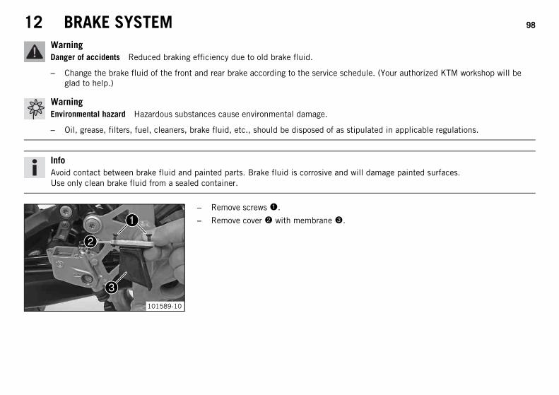
12 BRAKE SYSTEM 98
WarningDanger of accidents Reduced braking efficiency due to old brake fluid.
– Change the brake fluid of the front and rear brake according to the service schedule. (Your authorized KTM workshop will beglad to help.)
WarningEnvironmental hazard Hazardous substances cause environmental damage.
– Oil, grease, filters, fuel, cleaners, brake fluid, etc., should be disposed of as stipulated in applicable regulations.
InfoAvoid contact between brake fluid and painted parts. Brake fluid is corrosive and will damage painted surfaces.Use only clean brake fluid from a sealed container.
101589-10
– Remove screws 1.
– Remove cover 2 with membrane 3.

12 BRAKE SYSTEM 99
101590-10
– Add brake fluid to level A.
Brake fluid DOT 4 / DOT 5.1 ( p. 197)
– Position the cover with the membrane. Mount and tighten the screws.
InfoClean up overflowed or spilt brake fluid immediately with water.
12.12 Checking the rear brake linings
WarningDanger of accidents Reduced braking efficiency caused by worn brake linings.
– Change worn brake linings immediately. (Your authorized KTM workshop will be glad to help.)
NoteDanger of accidents Reduced braking efficiency caused by damaged brake discs.
– If the brake linings are not changed in time, the steel brake lining carriers grind on the brake disc. The braking effect is greatlyreduced and the brake discs are destroyed. Check the brake linings regularly.
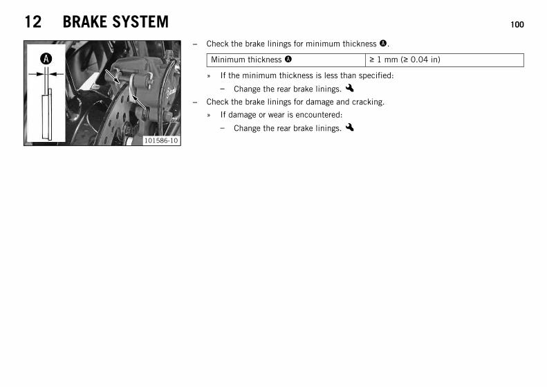
12 BRAKE SYSTEM 100
101586-10
– Check the brake linings for minimum thickness A.
Minimum thickness A ≥ 1 mm (≥ 0.04 in)
» If the minimum thickness is less than specified:
– Change the rear brake linings.x– Check the brake linings for damage and cracking.
» If damage or wear is encountered:
– Change the rear brake linings.x

13 WHEELS, TIRES 101
13.1 Removing the front wheelxPreparatory work– Raise the motorcycle with the rear wheel stand. ( p. 73)
– Raise the motorcycle with the front wheel stand. ( p. 74)
101587-10
Main work– Take the speed sensor cable out of the clamp.
– Remove screw 1 and pull wheel speed sensor 2 out of the hole with the sleeve.
– Remove screws 3 from both brake calipers.
– Press back the brake linings with a light lateral tilting of the brake calipers on the brakedisc. Pull the brake calipers carefully back from the brake discs and hang them to oneside.
InfoDo not pull the hand brake lever when the brake calipers are removed.
101591-10
– Loosen screws 4 and 5.
– Unscrew screw 4 about six turns and press your hand on the screw to push the wheelspindle out of the axle clamp. Remove screw 4.
WarningDanger of accidents Reduced braking efficiency due to damaged brake discs.
– Always lay down the wheel in such a way that the brake discs are not dam-aged.
– Holding the front wheel, withdraw the wheel spindle. Take the front wheel out of thefork.

13 WHEELS, TIRES 102
13.2 Installing the front wheelx
WarningDanger of accidents Reduced braking efficiency due to oil or grease on the brake discs.
– Always keep the brake discs free of oil and grease, and clean them with brake cleaner when necessary.
B00634-10
– Check the wheel bearing for damage and wear.
» If the wheel bearing is damaged or worn:
– Replace the wheel bearing.x– Clean, grease, and mount the left and right spacers and the shaft seal rings.
Long-life grease ( p. 202)
– Clean screw 1 and wheel spindle 2.
– Lift the front wheel into the fork, position it, and insert the wheel spindle.
The arrow on the spoke points in the direction of motion.
– Mount and tighten screw 1.
Guideline
Bolt, front axle M25x1.5 45 Nm(33.2 lbf ft)

13 WHEELS, TIRES 103
101587-11
– Slide the sleeve onto the wheel speed sensor 3 and push them into the hole together.Mount and tighten screw 4.
Guideline
Screw, wheel speed sensor M6 6 Nm(4.4 lbf ft)
Loctite® 243™
– Fasten the speed sensor cable in the bracket.
– Position the brake calipers and check that the brake linings are seated correctly.
– Mount screws 5 on both brake calipers but do not tighten yet.
– Operate the hand brake lever repeatedly until the brake linings are in contact with thebrake disc and there is a pressure point. Fix the hand brake lever in the activated posi-tion.
The brake calipers straighten.
– Tighten screws 5 on both brake calipers.
Guideline
Screw, front brake caliper M10x1.25 45 Nm(33.2 lbf ft)
Loctite® 243™
– Release the fixation of the hand brake lever.
– Take the motorcycle off of the front wheel stand. ( p. 74)
– Take the motorcycle off of the rear wheel stand. ( p. 73)

13 WHEELS, TIRES 104
101592-10
– Pull the front brake and compress the fork powerfully a few times.
The fork legs straighten.
– Tighten screws 6.
Guideline
Screw, fork stub M8 15 Nm(11.1 lbf ft)
13.3 Removing the rear wheelxPreparatory work– Raise the motorcycle with the rear wheel stand. ( p. 73)

13 WHEELS, TIRES 105
101593-10
Main work– Remove screw 1 and pull wheel speed sensor 2 out of the hole.
– Remove nut 3. Remove chain adjuster 4.
– Pull out wheel spindle 5 to the point where the chain adjuster is no longer in contactwith the adjusting screw.
101594-01
– Push the rear wheel forward as far as possible and take the chain off the rear sprocket.
– Withdraw the wheel spindle.
– Pull the rear wheel back until the brake caliper support is suspended freely between thebrake disc and rim.
WarningDanger of accidents Reduced braking efficiency due to damaged brake discs.
– Always lay down the wheel in such a way that the brake discs are not dam-aged.

13 WHEELS, TIRES 106
– Take the rear wheel carefully out of the swingarm without damaging the rim and/orbrake disc.
InfoDo not operate the foot brake when the rear wheel is removed.
13.4 Installing the rear wheelx
WarningDanger of accidents Reduced braking efficiency due to oil or grease on the brake discs.
– Always keep the brake discs free of oil and grease, and clean them with brake cleaner when necessary.
WarningDanger of accidents No braking effect when operating the rear brake.
– After installing the rear wheel, always operate the foot brake until the pressure point is reached.
B00635-10
Main work– Check the rear hub rubber dampers.x ( p. 108)
– Check the wheel bearing for damage and wear.
» If the wheel bearing is damaged or worn:
– Replace the wheel bearing.x– Remove bushing 1. Clean and grease the mating surfaces of the bushing and the shaft
seal ring.
Long-life grease ( p. 202)
– Install the bushing.
– Clean and grease the thread of the wheel spindle and nut.
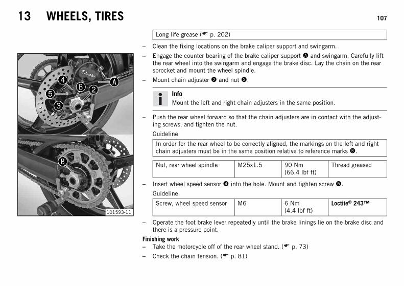
13 WHEELS, TIRES 107
Long-life grease ( p. 202)
– Clean the fixing locations on the brake caliper support and swingarm.
101593-11
– Engage the counter bearing of the brake caliper support A and swingarm. Carefully liftthe rear wheel into the swingarm and engage the brake disc. Lay the chain on the rearsprocket and mount the wheel spindle.
– Mount chain adjuster 2 and nut 3.
InfoMount the left and right chain adjusters in the same position.
– Push the rear wheel forward so that the chain adjusters are in contact with the adjust-ing screws, and tighten the nut.
Guideline
In order for the rear wheel to be correctly aligned, the markings on the left and rightchain adjusters must be in the same position relative to reference marks B.
Nut, rear wheel spindle M25x1.5 90 Nm(66.4 lbf ft)
Thread greased
– Insert wheel speed sensor 4 into the hole. Mount and tighten screw 5.
Guideline
Screw, wheel speed sensor M6 6 Nm(4.4 lbf ft)
Loctite® 243™
– Operate the foot brake lever repeatedly until the brake linings lie on the brake disc andthere is a pressure point.
Finishing work– Take the motorcycle off of the rear wheel stand. ( p. 73)
– Check the chain tension. ( p. 81)

13 WHEELS, TIRES 108
13.5 Checking the rear hub rubber dampersx
InfoThe engine power is transmitted from the rear sprocket to the rear wheel via 5 rubber dampers. They eventually wear out duringoperation. If the rubber dampers are not changed in time, the rear sprocket carrier and the rear hub will be damaged.
Preparatory work– Raise the motorcycle with the rear wheel stand. ( p. 73)
– Remove the rear wheel.x ( p. 104)
B00636-01
Main work– Remove the rear sprocket carrier.
– Check the rubber dampers of the rear hub for damage and wear.
» If the rubber dampers of the rear hub are damaged or worn:
– Change the rear hub shock absorber.x– Position the rear sprocket carrier.
InfoA pin/rubber damper pair that is low in play increases the service life of the rub-ber damper.
Finishing work– Install the rear wheel.x ( p. 106)
– Take the motorcycle off of the rear wheel stand. ( p. 73)
– Check the chain tension. ( p. 81)

13 WHEELS, TIRES 109
13.6 Checking the tire condition
WarningDanger of accidents Uncontrollable vehicle handling in the event of a flat tire.
– In the interest of safety, replace damaged or worn tires immediately. (Your authorized KTM workshop will be glad to help.)
WarningDanger of crashing Poor vehicle handling due to different tire tread patterns on front and rear wheels.
– The front and rear wheels must be fitted with tires with similar tread patterns to prevent loss of control over the vehicle.
WarningDanger of accidents Uncontrollable handling characteristic due to non-approved and/or non-recommended tires/wheels.
– Only tires/wheels approved by KTM and with the corresponding speed index should be used.
WarningDanger of accidents Reduced road grip with new tires.
– New tires have a smooth rolling surface and therefore cannot provide full road grip. The entire rolling surface must be rough-ened in the first 200 kilometers (124.3 miles) by moderate riding at alternating angles. The full grip levels are not achieveduntil the tires have been run in.
InfoThe type, condition and air pressure of the tires all have a major impact on the handling of the motorcycle.Worn tires have a negative effect on vehicle handling, especially on wet surfaces.

13 WHEELS, TIRES 110
400602-10
– Check the front and rear tires for cuts, run-in objects and other damage.
» If the tires exhibit cuts, run-in objects or other damage:
– Change the tires.
– Check the depth of the tread.
InfoNote local national regulations concerning the minimum tread depth.
Minimum tread depth ≥ 2 mm (≥ 0.08 in)
» If the tread depth is less than the minimum permissible depth:
– Change the tires.
– Check the age of the tires.
InfoThe tire's date of manufacture is usually part of the tire markings and is indi-cated by the last four digits of the DOT marking. The first two digits refer to theweek of manufacture and last two digits refer to the year of manufacture.KTM recommends that the tires be changed after 5 years at the latest, regard-less of the actual state of wear.
» If a tire is more than five years old:
– Change the tires.
13.7 Checking the tire air pressure
InfoLow tire air pressure leads to abnormal wear and overheating of the tire.Correct tire air pressure ensures optimal riding comfort and maximum tire service life.
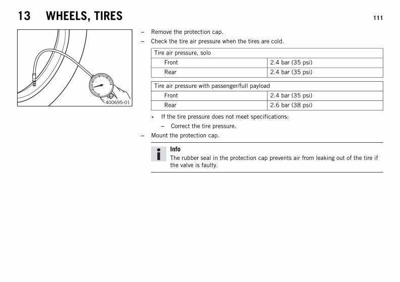
13 WHEELS, TIRES 111
400695-01
– Remove the protection cap.
– Check the tire air pressure when the tires are cold.
Tire air pressure, solo
Front 2.4 bar (35 psi)
Rear 2.4 bar (35 psi)
Tire air pressure with passenger/full payload
Front 2.4 bar (35 psi)
Rear 2.6 bar (38 psi)
» If the tire pressure does not meet specifications:
– Correct the tire pressure.
– Mount the protection cap.
InfoThe rubber seal in the protection cap prevents air from leaking out of the tire ifthe valve is faulty.

14 ELECTRICAL SYSTEM 112
14.1 Removing the batteryx
WarningRisk of injury Battery acid and battery gases cause serious chemical burns.
– Keep batteries out of the reach of children.
– Wear suitable protective clothing and goggles.
– Avoid contact with battery acid and battery gases.
– Keep the battery away from sparks or open flames. Charge only in well-ventilated areas.
– In the event of skin contact, rinse with large amounts of water. If battery acid gets in the eyes, rinse with water for at least 15minutes and contact a physician.
CautionDanger of accidents If the vehicle is operated with a discharged battery or without a battery, electronic components and safetyequipment may be damaged.
– Never operate the vehicle with a discharged battery or without a battery.
Preparatory work– Switch off all power consumers and switch off the engine.
– Remove the seat. ( p. 75)

14 ELECTRICAL SYSTEM 113
101595-10
Main work– Disconnect negative (minus) cable 1 of the battery.
101596-10
– Remove positive terminal cover 2.
– Disconnect the positive (plus) cable 3 of the battery.
– Detach rubber band 4.
– Pull the battery up and out of the battery holder.

14 ELECTRICAL SYSTEM 114
14.2 Installing the batteryx
101597-10
Main work– Position the battery in the battery holder.
InfoThe terminals of the battery must face in the direction of travel.
– Attach rubber band 1.
– Position washer A and detach positive cable 2 of the battery.
– Position positive terminal cover 3.
101598-10
– Position washer B and detach negative cable 4 of the battery.
Finishing work– Mount the seat. ( p. 76)
– Set the clock. ( p. 33)

14 ELECTRICAL SYSTEM 115
14.3 Recharging the batteryx
WarningRisk of injury Battery acid and battery gases cause serious chemical burns.
– Keep batteries out of the reach of children.
– Wear suitable protective clothing and goggles.
– Avoid contact with battery acid and battery gases.
– Keep the battery away from sparks or open flames. Charge only in well-ventilated areas.
– In the event of skin contact, rinse with large amounts of water. If battery acid gets in the eyes, rinse with water for at least 15minutes and contact a physician.
WarningEnvironmental hazard The battery contains elements that are harmful to the environment.
– Do not discard batteries with the household trash. Dispose of a defective battery in an environmentally compatible manner.Give the battery to your KTM dealer or to a recycling center that accepts used batteries.
WarningEnvironmental hazard Hazardous substances cause environmental damage.
– Oil, grease, filters, fuel, cleaners, brake fluid, etc., should be disposed of as stipulated in applicable regulations.

14 ELECTRICAL SYSTEM 116
InfoEven when there is no load on the battery, it discharges steadily.The charging level and the method of charging are very important for the service life of the battery.Rapid recharging with a high charging current shortens the battery's service life.If the charging current, charging voltage and charging time are exceeded, electrolyte escapes through the safety valves. Thisreduces the battery capacity.If the battery is depleted from starting the vehicle repeatedly, the battery must be charged immediately.If the battery is left in a discharged state for an extended period, it will become over-discharged and sulfate, destroying the battery.The battery is maintenance-free, i.e., the acid level does not have to be checked.
Preparatory work– Switch off all power consumers and switch off the engine.
– Remove the seat. ( p. 75)
– Disconnect the negative (minus) cable of the battery to avoid damage to the motorcy-cle's electronics.

14 ELECTRICAL SYSTEM 117
700588-01
Main work– Connect the battery charger to the battery. Switch on the battery charger.
Battery charger (58429074000)
You can also use the battery charger to test the rest potential and start potential of thebattery, and to test the alternator. With this device, you cannot overcharge the battery.
InfoNever remove lid 1.Charge the battery to no more than 10% of the capacity specified on batteryhousing 2.
– Switch off the charger after charging. Reconnect the battery.
Guideline
The charge current, charge voltage and charge time must not be exceeded.
Charge the battery regularly when themotorcycle is not in use
3 months
Finishing work– Mount the seat. ( p. 76)
14.4 Changing the main fuse
WarningFire hazard The electrical system can be overloaded if the wrong fuses are used.
– Use only fuses with the prescribed amperage. Never by-pass or repair fuses.

14 ELECTRICAL SYSTEM 118
InfoThe main fuse protects all power consumers of the vehicle. The main fuse is under the seat.
Preparatory work– Switch off all power consumers and switch off the engine.
– Remove the seat. ( p. 75)
101599-10
Main work– Remove protection covers 1.
– Remove the faulty main fuse 2.
InfoA defective fuse can be identified by the burned-out fuse wire A.A reserve fuse 3 is located in the starter relay.
– Install a new main fuse.
Fuse (58011109130) ( p. 190)
TipPlace the spare fuse in the starter relay so that it is available if needed.
– Attach the protection covers 1.
Finishing work– Mount the seat. ( p. 76)

14 ELECTRICAL SYSTEM 119
14.5 Changing the ABS fuses
WarningFire hazard The electrical system can be overloaded if the wrong fuses are used.
– Use only fuses with the prescribed amperage. Never by-pass or repair fuses.
InfoTwo fuses for the ABS are located under the seat. These fuses protect the return pump and the hydraulic unit of the ABS. The thirdfuse, which protects the ABS control unit, is located in the fuse box.
Preparatory work– Switch off all power consumers and switch off the engine.
– Remove the seat. ( p. 75)
101600-10
To change the fuse of the ABS hydraulic unit:– Take off the protection cap and remove fuse 1.
– Insert the new fuse.
Fuse (58011109130)
– Mount the protection cap.

14 ELECTRICAL SYSTEM 120
101601-10
To change the fuse of the ABS return pump:– Take off the protection cap and remove fuse 2.
– Insert the new fuse.
Fuse (58011109130)
– Mount the protection cap.
Finishing work– Mount the seat. ( p. 76)
14.6 Changing the fuses of individual power consumers
WarningFire hazard The electrical system can be overloaded if the wrong fuses are used.
– Use only fuses with the prescribed amperage. Never by-pass or repair fuses.
InfoThe fuse box containing the fuses of individual power consumers is located under the seat.
Preparatory work– Switch off all power consumers and switch off the engine.
– Remove the seat. ( p. 75)

14 ELECTRICAL SYSTEM 121
101602-10
Main work– Open fuse box cover 1.
– Check the fuses.
InfoA faulty fuse can be identified by the burned-out fuse wire A.
– Remove the faulty fuse.
Guideline
Fuse 1 - 10 A - ignition, fuel pump, hazard warning flasher
Fuse 2 - 15 A - high beam, low beam, parking light, tail light, license plate lamp
Fuse 3 - 10 A - horn, brake light, turn signal
Fuse 4 - 10 A - radiator fan
Fuse 5 - 10 A - ignition (EFI control unit), immobilizer
Fuse 6 - 10 A - combination instrument, auxiliary equipment (permanent positive),alarm system (optional), socket
Fuse 7 - 10 A - supplementary equipment (accessories connected to the ignitionswitch)
Fuse 8 - 10 A - ABS
Fuse 9 - not used
Fuse 10 - not used
Fuse SPARE - 10 A/15 A - spare fuses
– Use spare fuses with the correct rating only.
Fuse (75011088010) ( p. 189)
Fuse (75011088015) ( p. 189)

14 ELECTRICAL SYSTEM 122
TipInsert a spare fuse so that it is available if needed.
– Close the fuse box cover.
Finishing work– Mount the seat. ( p. 76)
14.7 Changing the headlight bulb
NoteDamage to reflector Reduced brightness.
– Grease on the lamp will evaporate due to the heat and be deposited on the reflector. Clean the lamp and keep it free of grease beforemounting.
Preparatory work– Switch off all power consumers and switch off the engine.
101145-10
Main work– Remove screws 1.

14 ELECTRICAL SYSTEM 123
101146-10
– Cover the fender with a cloth.
– Swing the headlight mask forward and pull it upward out of holding lugs 2.
700592-10
– Disconnect connector 3.
– Remove protection cap 4.
700593-01
– Push off retaining clamp 5 on both sides, squeeze and fold down.
– Remove headlight bulb 6.
– Position the new headlight bulb in the headlight housing.
Low beam/high beam (H4/socket P43t) ( p. 190)
InfoInsert the headlight bulb so that the catches latch into the recesses.

14 ELECTRICAL SYSTEM 124
– Position the retaining clamp.
700592-10
– Mount protection cap 4.
– Plug in connector 3.
101146-11
– Position holes 7 onto holding lugs 2.

14 ELECTRICAL SYSTEM 125
101145-10
– Position the headlight mask. Mount and tighten screws 1.
Guideline
Remaining chassis screws M6 10 Nm (7.4 lbf ft)
– Check that the lighting is functioning properly.
14.8 Changing the parking light bulb
NoteDamage to reflector Reduced brightness.
– Grease on the lamp will evaporate due to the heat and be deposited on the reflector. Clean the lamp and keep it free of grease beforemounting.
Preparatory work– Switch off all power consumers and switch off the engine.
101145-10
Main work– Remove screws 1.
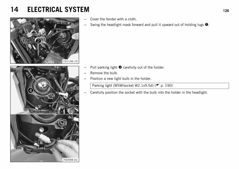
14 ELECTRICAL SYSTEM 126
101146-10
– Cover the fender with a cloth.
– Swing the headlight mask forward and pull it upward out of holding lugs 2.
700594-01
– Pull parking light 4 carefully out of the holder.
– Remove the bulb.
– Position a new light bulb in the holder.
Parking light (W5W/socket W2.1x9.5d) ( p. 190)
– Carefully position the socket with the bulb into the holder in the headlight.
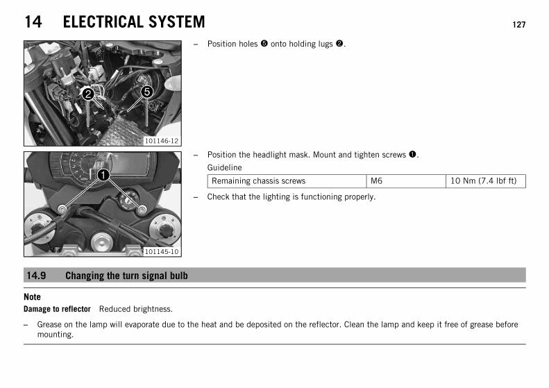
14 ELECTRICAL SYSTEM 127
101146-12
– Position holes 5 onto holding lugs 2.
101145-10
– Position the headlight mask. Mount and tighten screws 1.
Guideline
Remaining chassis screws M6 10 Nm (7.4 lbf ft)
– Check that the lighting is functioning properly.
14.9 Changing the turn signal bulb
NoteDamage to reflector Reduced brightness.
– Grease on the lamp will evaporate due to the heat and be deposited on the reflector. Clean the lamp and keep it free of grease beforemounting.

14 ELECTRICAL SYSTEM 128
101147-10
– Remove the screw on the rear of the turn signal housing.
– Carefully remove diffuser 1.
– Press bulb 2 carefully into the socket, turn it counterclockwise by about 30°, and pullit out of the socket.
– Press the new bulb carefully into the socket and turn it clockwise until it stops.
Turn signal (RY10W/socket BAU15s) ( p. 190)
– Check the turn signal to make sure it is functioning properly.
– Position the diffuser.
– Insert the screw and first turn it counterclockwise until it engages in the thread. Tightenthe screw slightly.
14.10 Changing the brake light bulb
NoteDamage to reflector Reduced brightness.
– Grease on the lamp will evaporate due to the heat and be deposited on the reflector. Clean the lamp and keep it free of grease beforemounting.
Preparatory work– Remove the seat. ( p. 75)

14 ELECTRICAL SYSTEM 129
101603-10
Main work– Remove screws 1.
– Remove the grab handles.
101604-10
– Remove screws 2.
– Remove screws 3 on the left and right rear side part.
– Remove the rear side part.
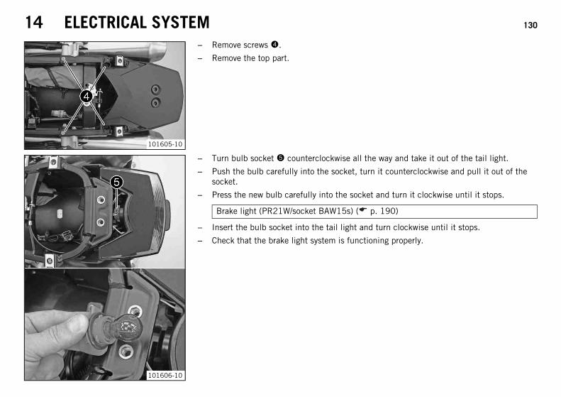
14 ELECTRICAL SYSTEM 130
101605-10
– Remove screws 4.
– Remove the top part.
101606-10
– Turn bulb socket 5 counterclockwise all the way and take it out of the tail light.
– Push the bulb carefully into the socket, turn it counterclockwise and pull it out of thesocket.
– Press the new bulb carefully into the socket and turn it clockwise until it stops.
Brake light (PR21W/socket BAW15s) ( p. 190)
– Insert the bulb socket into the tail light and turn clockwise until it stops.
– Check that the brake light system is functioning properly.

14 ELECTRICAL SYSTEM 131
101605-10
– Position the rear top part.
– Mount and tighten screws 4.
Guideline
Remaining chassis screws M6 10 Nm (7.4 lbf ft)
101604-10
– Position the rear side parts.
– Mount and tighten screws 2.
Guideline
Remaining chassis screws M5 5 Nm (3.7 lbf ft)
Remaining frame bolts EJOT PT K50x12T20
1.2 Nm(0.89 lbf ft)
– Mount and tighten screws 3 on the left and right rear side part.
Guideline
Remaining frame bolts EJOT PT K50x12T20
1.2 Nm(0.89 lbf ft)

14 ELECTRICAL SYSTEM 132
101603-10
– Position the grab handles.
– Mount and tighten screws 1.
Guideline
Screw, handrail M8 20 Nm(14.8 lbf ft)
Finishing work– Mount the seat. ( p. 76)
14.11 Changing the tail light bulbs
NoteDamage to reflector Reduced brightness.
– Grease on the lamp will evaporate due to the heat and be deposited on the reflector. Clean the lamp and keep it free of grease beforemounting.
Preparatory work– Remove the seat. ( p. 75)
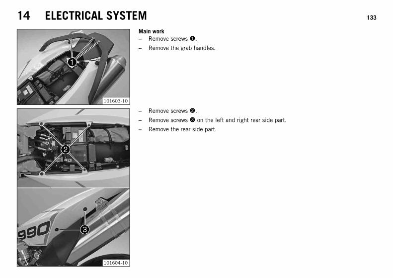
14 ELECTRICAL SYSTEM 133
101603-10
Main work– Remove screws 1.
– Remove the grab handles.
101604-10
– Remove screws 2.
– Remove screws 3 on the left and right rear side part.
– Remove the rear side part.

14 ELECTRICAL SYSTEM 134
101605-10
– Remove screws 4.
– Remove the top part.
101152-10
– Carefully pull bulb sockets 5 out of the holder.
– Remove the bulb.
– Position a new light bulb in the holder.
Tail light (WR5W/socket W2.1x9.5d) ( p. 190)
– Carefully position the sockets with the bulbs into the holder in the tail light.
– Check that the tail light bulbs are functioning properly.

14 ELECTRICAL SYSTEM 135
101605-10
– Position the rear top part.
– Mount and tighten screws 4.
Guideline
Remaining chassis screws M6 10 Nm (7.4 lbf ft)
101604-10
– Position the rear side parts.
– Mount and tighten screws 2.
Guideline
Remaining chassis screws M5 5 Nm (3.7 lbf ft)
Remaining frame bolts EJOT PT K50x12T20
1.2 Nm(0.89 lbf ft)
– Mount and tighten screws 3 on the left and right rear side part.
Guideline
Remaining frame bolts EJOT PT K50x12T20
1.2 Nm(0.89 lbf ft)
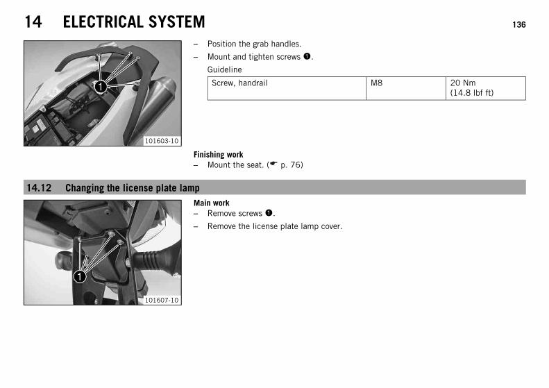
14 ELECTRICAL SYSTEM 136
101603-10
– Position the grab handles.
– Mount and tighten screws 1.
Guideline
Screw, handrail M8 20 Nm(14.8 lbf ft)
Finishing work– Mount the seat. ( p. 76)
14.12 Changing the license plate lamp
101607-10
Main work– Remove screws 1.
– Remove the license plate lamp cover.

14 ELECTRICAL SYSTEM 137
101608-10
– Carefully pull socket 2 out of the holder.
– Remove the bulb.
– Position a new light bulb in the holder.
License plate lamp (W5W/socket W2.1x9.5d) ( p. 190)
– Carefully position the socket with the bulb into the holder.
101607-10
– Position the cover.
– Mount and tighten screws 1.
Finishing work– Check that the license plate lamp is functioning properly.
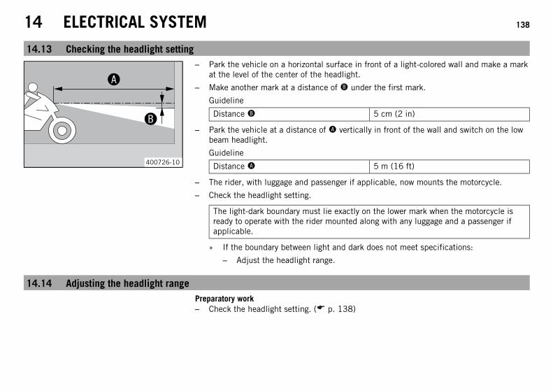
14 ELECTRICAL SYSTEM 138
14.13 Checking the headlight setting
00AA
00BB
400726-10
– Park the vehicle on a horizontal surface in front of a light-colored wall and make a markat the level of the center of the headlight.
– Make another mark at a distance of B under the first mark.
Guideline
Distance B 5 cm (2 in)
– Park the vehicle at a distance of A vertically in front of the wall and switch on the lowbeam headlight.
Guideline
Distance A 5 m (16 ft)
– The rider, with luggage and passenger if applicable, now mounts the motorcycle.
– Check the headlight setting.
The light-dark boundary must lie exactly on the lower mark when the motorcycle isready to operate with the rider mounted along with any luggage and a passenger ifapplicable.
» If the boundary between light and dark does not meet specifications:
– Adjust the headlight range.
14.14 Adjusting the headlight rangePreparatory work– Check the headlight setting. ( p. 138)

14 ELECTRICAL SYSTEM 139
101153-10
Main work– Turn adjusting screw 1 to adjust the headlight range.
Guideline
For a motorcycle with rider, the light/dark boundary must be exactly on the lowermark (the mark is created in: Checking headlight adjustment).
InfoTurn clockwise to increase the headlight range; turn counterclockwise to reducethe headlight range.If you have a payload, you may have to correct the headlight range.
14.15 Activating/deactivating the ignition key
InfoThe orange programming key must only be used for activating and deactivating!If a black ignition key is lost or replaced, the black ignition keys must be individually activated/deactivated using the orange pro-gramming key. This will also prevent the vehicle from being operated without authorization with the lost black ignition key.You can activate or deactivate up to four black ignition keys. Only the black ignition keys programmed during an activation proce-dure are valid. All black ignition keys not programmed during the activation procedure are invalid, but can be reprogrammed in afurther activation procedure.

14 ELECTRICAL SYSTEM 140
401184-10
Loss of a black ignition key (second black ignition key available):The following procedure deactivates all activated black ignition keys that are notincluded in the procedure.
– Press the emergency OFF switch into the position .
101609-10
– Insert the orange programming key in the ignition lock.
– Switch on the ignition by turning the orange programming key to the ON position .
FI warning lamp (MIL) lights up, switches off, and then starts to flash.
Immobilizer indicator lamp lights up.
– Switch off the ignition by turning the orange programming key to the OFF position .
– Pull out the orange programming key.
– Insert the black ignition key in the ignition lock.
– Switch on the ignition by turning the ignition key to the ON position.
FI warning lamp (MIL) lights up, switches off, and then starts to flash.
The immobilizer indicator lamp lights up, switches off briefly, and switcheson again.
– Switch off the ignition by turning the ignition key to the OFF position.
– Remove the black ignition key.
– Insert the orange programming key in the ignition lock.
– Switch on the ignition by turning the orange programming key to the ON position .
FI warning lamp (MIL) lights up, switches off, and then starts to flash.

14 ELECTRICAL SYSTEM 141
Immobilizer indicator lamp lights up, switches off briefly and flashes; thenumber of flashes equals the number of functional black ignition keys includ-ing the orange programming key. In this case, twice.
– Switch off the ignition by turning the orange programming key to the OFF position .
– Pull out the orange programming key.
The lost black ignition key is deactivated.
The existing black ignition key is reactivated.
401184-11
Loss of both black ignition keys (no black ignition key available):This procedure is important to prevent misuse of the lost black ignition key.
– Press the emergency OFF switch into the position .
101609-10
– Insert the orange programming key in the ignition lock.
– Switch on the ignition by turning the orange programming key to the ON position .
FI warning lamp (MIL) lights up, switches off, and then starts to flash.
Immobilizer indicator lamp lights up.
– Switch off the ignition by turning the orange programming key to the OFF position .
– Switch on the ignition by turning the orange programming key to the ON position .
FI warning lamp (MIL) lights up, switches off, and then starts to flash.
Immobilizer indicator lamp lights up, switches off briefly and flashes; thenumber of flashes equals the number of functional black ignition keys includ-ing the orange programming key. In this case once, since all black ignition keysare deactivated.

14 ELECTRICAL SYSTEM 142
– Switch off the ignition by turning the orange programming key to the OFF position .
– Pull out the orange programming key.
All black ignition keys are deactivated.
– Order a new black ignition key according to the key number on the KEYCODECARDand activate it.
Activating the ignition key:– Press the emergency OFF switch into the position .
– Insert the orange programming key in the ignition lock.
– Switch on the ignition by turning the orange programming key to the ON position .
FI warning lamp (MIL) lights up, switches off, and then starts to flash.
Immobilizer indicator lamp lights up.
– Switch off the ignition by turning the orange programming key to the OFF position .
– Pull out the orange programming key.
– Insert the black ignition key in the ignition lock.
– Switch on the ignition by turning the ignition key to the ON position.
FI warning lamp (MIL) lights up, switches off, and then starts to flash.
The immobilizer indicator lamp lights up, switches off briefly, and lights upagain.
– Switch off the ignition by turning the ignition key to the OFF position.
– Remove the black ignition key.
– To activate further ignition keys, repeat the last 4 steps with the respective ignitionkey.
– Insert the orange programming key into the ignition lock.
– Switch on the ignition by turning the orange programming key to the ON position .
FI warning lamp (MIL) lights up, switches off, and then starts to flash.

14 ELECTRICAL SYSTEM 143
The immobilizer indicator lamp lights up, switches off briefly and flashes;the number of flashes equals the number of functional black ignition keysincluding the orange programming key.
– Switch off the ignition by turning the orange programming key to the OFF position .
– Pull out the orange programming key.
All black ignition keys are activated included in this job sequence are activated.

15 COOLING SYSTEM 144
15.1 Cooling system
101155-10
The water pump 1 in the engine forces the coolant to flow.The pressure in the cooling system resulting from heat is regulated by a valve in the radia-tor cap. This permits the specified coolant temperature without causing any malfunctions.
125 °C (257 °F)
700621-10
Cooling takes place by means of the air stream and a radiator fan, which is controlled by athermoswitch.The lower the speed, the less the cooling effect. Dirty cooling fins also reduce the coolingeffect.The heat expansion causes the surplus coolant to flow into the compensating tank 2. Whenthe temperature falls, this surplus coolant is sucked back into the cooling system.
15.2 Checking the antifreeze and coolant level
WarningDanger of scalding During motorcycle operation, the coolant gets very hot and is under pressure.
– Do not remove the radiator cap, radiator hoses or other cooling system components when the engine is hot. Allow the engineand cooling system to cool down. In case of scalding, rinse immediately with lukewarm water.
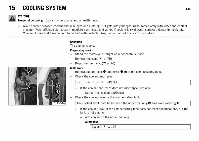
15 COOLING SYSTEM 145
WarningDanger of poisoning Coolant is poisonous and a health hazard.
– Avoid contact between coolant and skin, eyes and clothing. If it gets into your eyes, rinse immediately with water and contacta doctor. Wash affected skin areas immediately with soap and water. If coolant is swallowed, contact a doctor immediately.Change clothes that have come into contact with coolants. Keep coolant out of the reach of children.
ConditionThe engine is cold.
Preparatory work– Stand the motorcycle upright on a horizontal surface.
– Remove the seat. ( p. 75)
– Reset the fuel tank. ( p. 76)
101156-10
Main work– Remove radiator cap 1 and cover 2 from the compensating tank.
– Check the coolant antifreeze.
−25… −45 °C (−13… −49 °F)
» If the coolant antifreeze does not meet specifications:
– Correct the coolant antifreeze.
– Check the coolant level in the compensating tank.
The coolant level must be between the upper marking 3 and lower marking 4.
» If the coolant level in the compensating tank does not meet specifications, but thetank is not empty:
– Add coolant to the upper marking.
Alternative 1
Coolant ( p. 197)
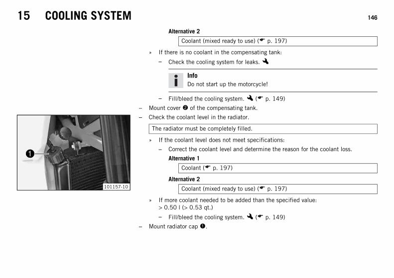
15 COOLING SYSTEM 146
Alternative 2
Coolant (mixed ready to use) ( p. 197)
» If there is no coolant in the compensating tank:
– Check the cooling system for leaks.x
InfoDo not start up the motorcycle!
– Fill/bleed the cooling system.x ( p. 149)
– Mount cover 2 of the compensating tank.
101157-10
– Check the coolant level in the radiator.
The radiator must be completely filled.
» If the coolant level does not meet specifications:
– Correct the coolant level and determine the reason for the coolant loss.
Alternative 1
Coolant ( p. 197)
Alternative 2
Coolant (mixed ready to use) ( p. 197)
» If more coolant needed to be added than the specified value:> 0.50 l (> 0.53 qt.)
– Fill/bleed the cooling system.x ( p. 149)
– Mount radiator cap 1.

15 COOLING SYSTEM 147
15.3 Checking the coolant level in the compensating tank
WarningDanger of scalding During motorcycle operation, the coolant gets very hot and is under pressure.
– Do not remove the radiator cap, radiator hoses or other cooling system components when the engine is hot. Allow the engineand cooling system to cool down. In case of scalding, rinse immediately with lukewarm water.
WarningDanger of poisoning Coolant is poisonous and a health hazard.
– Avoid contact between coolant and skin, eyes and clothing. If it gets into your eyes, rinse immediately with water and contacta doctor. Wash affected skin areas immediately with soap and water. If coolant is swallowed, contact a doctor immediately.Change clothes that have come into contact with coolants. Keep coolant out of the reach of children.
ConditionThe engine is cold.The radiator is completely full.
Preparatory work– Stand the motorcycle on a horizontal surface.
101158-10
Main work– Check the coolant level in the compensating tank 1.
The coolant level must be between the upper marking 2 and lower marking 3.
» If the coolant level in the compensating tank does not meet specifications, but thetank is not empty:
– Remove the compensating tank cover.
– Add coolant to the upper marking.
Alternative 1
Coolant ( p. 197)

15 COOLING SYSTEM 148
Alternative 2
Coolant (mixed ready to use) ( p. 197)
– Mount the cover of the compensating tank.
» If there is no coolant in the compensating tank:
– Check the cooling system for leaks.x
InfoDo not start up the motorcycle!
– Fill/bleed the cooling system.x ( p. 149)
15.4 Draining the coolantx
WarningDanger of scalding During motorcycle operation, the coolant gets very hot and is under pressure.
– Do not remove the radiator cap, radiator hoses or other cooling system components when the engine is hot. Allow the engineand cooling system to cool down. In case of scalding, rinse immediately with lukewarm water.
WarningDanger of poisoning Coolant is poisonous and a health hazard.
– Avoid contact between coolant and skin, eyes and clothing. If it gets into your eyes, rinse immediately with water and contacta doctor. Wash affected skin areas immediately with soap and water. If coolant is swallowed, contact a doctor immediately.Change clothes that have come into contact with coolants. Keep coolant out of the reach of children.
Preparatory work– Remove the seat. ( p. 75)
– Reset the fuel tank. ( p. 76)

15 COOLING SYSTEM 149
101159-10
Main work– Place a suitable container under the radiator.
– Remove radiator cap 1.
– Remove screw 2.
– Completely drain the coolant.
– Mount screw 2 with a new seal ring and tighten it.
Guideline
Remaining chassis screws M6 10 Nm (7.4 lbf ft)
101160-10
– Place a suitable container under the engine.
– Remove screw 3.
– Completely drain the coolant.
– Mount screw 3 with a new seal ring and tighten it.
Guideline
Screw, water pump cover M6 10 Nm (7.4 lbf ft)
15.5 Filling/bleeding the cooling systemx
WarningDanger of poisoning Coolant is poisonous and a health hazard.
– Avoid contact between coolant and skin, eyes and clothing. If it gets into your eyes, rinse immediately with water and contacta doctor. Wash affected skin areas immediately with soap and water. If coolant is swallowed, contact a doctor immediately.Change clothes that have come into contact with coolants. Keep coolant out of the reach of children.

15 COOLING SYSTEM 150
Preparatory work– Remove the seat. ( p. 75)
– Reset the fuel tank. ( p. 76)
101161-10
Main work– Ensure that the drain plug on the radiator and the water pump cover are tightened.
– Remove bleeder screw 1.
00AA
400677-10
– Position the vehicle as shown and secure it against rolling. Height difference A mustbe reached.
Guideline
Height difference A 50 cm (19.7 in)
InfoTo make sure that all of the air can escape from the cooling system, raise thefront of the vehicle. A poorly bled cooling system is less effective at cooling andthe engine can overheat.

15 COOLING SYSTEM 151
101162-10
– Remove the radiator cap and pour in coolant until it emerges without bubbles at thevent hole, and then immediately mount and tighten the bleeder screw 1.
Alternative 1
Coolant ( p. 197)
Alternative 2
Coolant (mixed ready to use) ( p. 197)
– Fill the radiator completely with coolant. Mount the radiator cap.
– Lean the vehicle on the side stand.
– Check the coolant level in the compensating tank. ( p. 147)
DangerDanger of poisoning Exhaust gases are toxic and inhaling them may result inunconsciousness and/or death.
– When running the engine, always make sure there is sufficient ventilation,and do not start or run the engine in an enclosed space without an effectiveexhaust extraction system.
– Start the engine and run it until it reaches operating temperature.
Six bars of the temperature display light up.
– Stop the engine and allow it to cool down.
– When the engine is cool, check the coolant level in the radiator and add coolant if nec-essary.
– Check the coolant level in the compensating tank. ( p. 147)
Finishing work– Position the fuel tank. ( p. 77)
– Mount the seat. ( p. 76)
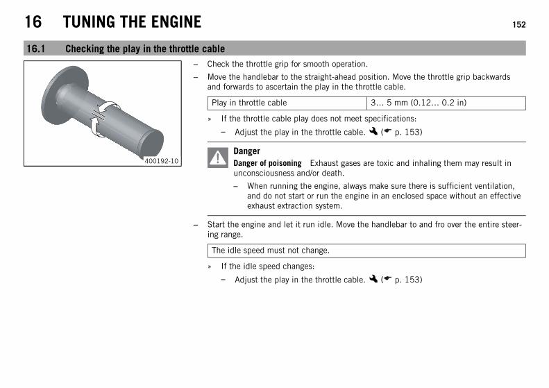
16 TUNING THE ENGINE 152
16.1 Checking the play in the throttle cable
400192-10
– Check the throttle grip for smooth operation.
– Move the handlebar to the straight-ahead position. Move the throttle grip backwardsand forwards to ascertain the play in the throttle cable.
Play in throttle cable 3… 5 mm (0.12… 0.2 in)
» If the throttle cable play does not meet specifications:
– Adjust the play in the throttle cable.x ( p. 153)
DangerDanger of poisoning Exhaust gases are toxic and inhaling them may result inunconsciousness and/or death.
– When running the engine, always make sure there is sufficient ventilation,and do not start or run the engine in an enclosed space without an effectiveexhaust extraction system.
– Start the engine and let it run idle. Move the handlebar to and fro over the entire steer-ing range.
The idle speed must not change.
» If the idle speed changes:
– Adjust the play in the throttle cable.x ( p. 153)

16 TUNING THE ENGINE 153
16.2 Adjusting the play in the throttle cablex
101610-10
– Move the handlebar to the straight-ahead position.
– Use the KTM diagnostics tool to set the throttle stepper motor to the basic position.
– Push back sleeve 1.
– Loosen lock nut 2.
– Set the play in the throttle cable by turning adjusting screw 3.
Guideline
Play in throttle cable 3… 5 mm (0.12… 0.2 in)
– Tighten lock nut 2.
– Slide on sleeves 1.
– Check the throttle grip for ease of movement.
16.3 Plug-in connection, ignition timing map
101611-10
The plug-in connection is located under the seat in front of the tail light.By disconnecting the connector, the ignition timing map for fuel with an octane ratingbelow 95 (ROZ 95/RON 95/PON 91) is activated. While the engine will have a slightlylower power output, this setting prevents engine damage by hindering spark knocking dueto poor fuel quality.
Possible states• Plug-in connection disconnected – Fuel with an octane rating of 80 to 94 (RON) can
be used for one tank full.• Plug-in connection closed – Fuel with an octane rating of 95 or higher can be used.

16 TUNING THE ENGINE 154
16.4 Adjusting the ignition curve to the fuel qualityPreparatory work– Switch off the ignition by turning the ignition key to the OFF position.
– Remove the seat. ( p. 75)
To activate the ignition curve for low octane fuel:
NoteEngine failure Low-quality fuel damages the engine.
– Operate the vehicle with fuel with an octane rating below 95 (ROZ 95/RON 95/PON 91) for no more than one tank full.
– The ignition curve must be adjusted to low octane fuel.
– Disconnect the connector.
Plug-in connection disconnected – Fuel with an octane rating of 80 to 94 (RON) can be used for one tank full. ( p. 153)
Activate the ignition curve for fuel with an octane rating of 95 or higher (ROZ 95/RON 95/PON 91):– Join the connector.
Plug-in connection closed – Fuel with an octane rating of 95 or higher can be used. ( p. 153)
Finishing work– Mount the seat. ( p. 76)

16 TUNING THE ENGINE 155
16.5 Checking the basic position of the shift lever
000AA
400692-10
– Sit on the vehicle in the riding position and determine the distance A between theupper edge of your boot and the shift lever.
Distance between shift lever and upperedge of boot
10… 20 mm (0.39… 0.79 in)
» If the distance does not meet specifications:
– Adjust the basic position of the shift lever.x ( p. 155)
16.6 Adjusting the basic position of the shift leverx
101172-10
– Remove screw 1 and remove shift lever 2.
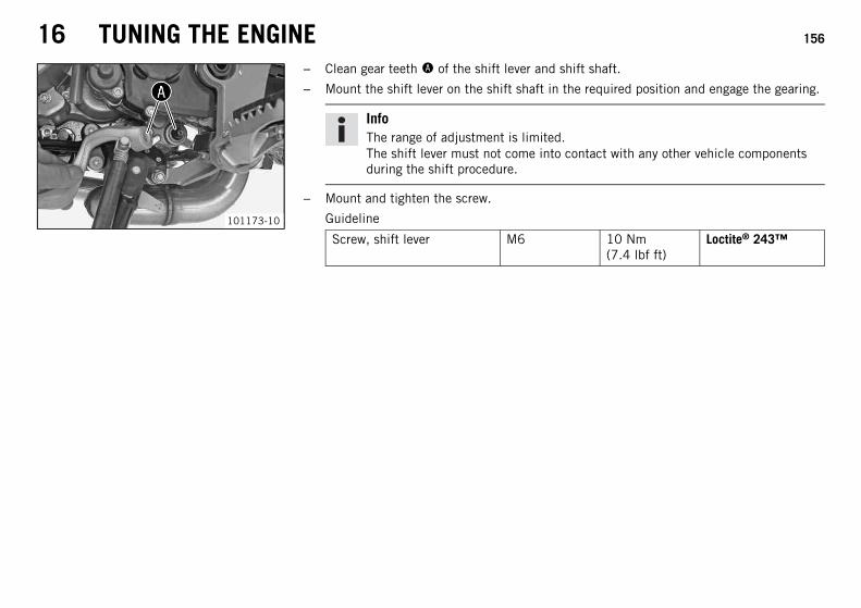
16 TUNING THE ENGINE 156
101173-10
– Clean gear teeth A of the shift lever and shift shaft.
– Mount the shift lever on the shift shaft in the required position and engage the gearing.
InfoThe range of adjustment is limited.The shift lever must not come into contact with any other vehicle componentsduring the shift procedure.
– Mount and tighten the screw.
Guideline
Screw, shift lever M6 10 Nm(7.4 lbf ft)
Loctite® 243™

17 SERVICE WORK ON THE ENGINE 157
17.1 Checking the engine oil levelPreparatory work
DangerDanger of poisoning Exhaust gases are toxic and inhaling them may result inunconsciousness and/or death.
– When running the engine, always make sure there is sufficient ventilation,and do not start or run the engine in an enclosed space without an effectiveexhaust extraction system.
– Start the engine and run it until it reaches operating temperature.
Six bars of the temperature display light up.
101168-10
Main work– Switch off the engine.
– Park the motorcycle on a horizontal surface in a vertical position (not on the sidestand).
InfoAfter switching off the engine, wait one minute before checking the level.
– Check the engine oil level at oil level viewer 1.
The engine oil level must be between the upper marking 2 and lower marking 3.
» If the engine oil level is not at the specified level:
– Add engine oil. ( p. 164)

17 SERVICE WORK ON THE ENGINE 158
17.2 Changing the engine oil and filter, cleaning the oil screensx
B00119-01
– Drain the engine oil, change the oil filter, and clean the oil screens.x ( p. 158)
– Fill up with engine oil.x ( p. 163)
17.3 Draining the engine oil, changing the oil filter, and cleaning the oil screensx
WarningDanger of scalding Engine oil and gear oil get very hot when the motorcycle is ridden.
– Wear appropriate protective clothing and safety gloves. In case of burns, rinse immediately with lukewarm water.
WarningEnvironmental hazard Hazardous substances cause environmental damage.
– Oil, grease, filters, fuel, cleaners, brake fluid, etc., should be disposed of as stipulated in applicable regulations.
InfoDrain the engine oil only when the engine is warm.

17 SERVICE WORK ON THE ENGINE 159
700611-10
– Place a suitable container under the engine.
– Remove the oil drain plug 1 with the magnet and seal ring.
– Fully drain the engine oil out of the engine.
700610-10
– Remove screws 2 and cover 3.
700612-10
– Pull oil screen 4 out of the engine case with pliers.

17 SERVICE WORK ON THE ENGINE 160
101171-10
– Place a suitable container under the engine.
– Remove oil drain plug 5.
– Fully drain the engine oil out of the oil tank.
– Remove screws 6 and move oil line 7 to one side.
700615-10
– Pull oil screen 8 out of the oil tank.
700617-10
– Remove fitting 9 and move the oil line to one side.
– Remove screws . Remove the oil filter cover bk with the O-ring.
– Pull oil filter bl out of the oil filter housing.
Circlip pliers reverse (51012011000)
– Completely drain the engine oil.
– Clean all oil screens and oil drain plugs with a magnet.
– Clean all sealing surfaces.

17 SERVICE WORK ON THE ENGINE 161
700618-10
– Insert oil filter bl.
– Lubricate the O-ring of the oil filter cover.
– Mount the oil filter cover bk. Mount and tighten the screws.
Guideline
Remaining engine screws M5 6 Nm (4.4 lbf ft)
– Position the oil line. Mount and tighten fitting 9.
Guideline
Nut, oil line M16x1.5 25 Nm(18.4 lbf ft)
700614-10
– Check seal ring bm of the oil screen for damage and correct seating.
– Insert oil screen 8 into the oil tank.

17 SERVICE WORK ON THE ENGINE 162
101171-10
– Position oil line 7. Mount and tighten screws 6.
Guideline
Remaining engine screws M6 10 Nm (7.4 lbf ft)
– Mount oil drain plug 5 with the magnet and new gasket and tighten.
Guideline
Oil drain plug with magnet M12x1.5 25 Nm(18.4 lbf ft)
700611-10
– Mount oil drain plug 1 with the magnet and new seal ring and tighten.
Guideline
Oil drain plug with magnet M22x1.5 35 Nm(25.8 lbf ft)
700616-10
– Slide oil screen 4 into the engine case with the TOP marking facing up.
– Check the form ring in cover 3 for damage and correct seating.
– Position the cover. Mount and tighten the screws.
Guideline
Screw, clutch cover M6 10 Nm (7.4 lbf ft)

17 SERVICE WORK ON THE ENGINE 163
17.4 Filling up with engine oilx
InfoToo little engine oil or poor-quality engine oil results in premature wear to the engine.
101169-10
– The oil must be added in two steps.
Engine oil 3.0 l (3.2 qt.) Externaltemperature:≥ 0 °C (≥ 32 °F)
Engine oil(SAE 10W/50)( p. 198)
Externaltemperature:< 0 °C (< 32 °F)
Engine oil (SAE5W/40) ( p. 198)
– Remove plug 1 and add engine oil to the top marking 2.
– Mount the plug.
DangerDanger of poisoning Exhaust gases are toxic and inhaling them may result inunconsciousness and/or death.
– When running the engine, always make sure there is sufficient ventilation,and do not start or run the engine in an enclosed space without an effectiveexhaust extraction system.
– Start the engine and run it until it reaches operating temperature.
Six bars of the temperature display light up.
– Check the lubrication system for leaks.
– Switch off the engine.
– Park the motorcycle on a horizontal surface in a vertical position (not on the sidestand).

17 SERVICE WORK ON THE ENGINE 164
– Remove the plug.
– Add engine oil to the top marking 2.
– Mount the plug.
17.5 Adding engine oil
InfoToo little engine oil or poor-quality engine oil results in premature wear to the engine.The engine oil level must be corrected when the engine is warm.
101169-10
– Remove plug 1 and add engine oil to the top marking 2.
ConditionExternal temperature: ≥ 0 °C (≥ 32 °F)
Engine oil (SAE 10W/50) ( p. 198)
ConditionExternal temperature: < 0 °C (< 32 °F)
Engine oil (SAE 5W/40) ( p. 198)
InfoFor optimal performance of the engine oil, do not mix different types of engineoil.We recommend changing the engine oil, if necessary.
– Mount the plug.

18 CLEANING, CARE 165
18.1 Cleaning motorcycle
NoteMaterial damage Damage and destruction of components by high-pressure cleaning equipment.
– When cleaning the vehicle with a pressure cleaner, do not point the water jet directly onto electrical components, connectors, cables,bearings, etc. Maintain a minimum distance of 60 cm between the nozzle of the pressure cleaner and the component. Excessive pres-sure can cause malfunctions or destroy these parts.
WarningEnvironmental hazard Hazardous substances cause environmental damage.
– Oil, grease, filters, fuel, cleaners, brake fluid, etc., should be disposed of as stipulated in applicable regulations.
InfoIf you clean the motorcycle regularly, its value and appearance will be maintained over a long period.Avoid direct sunshine on the motorcycle during cleaning.
401061-01
– Close off the exhaust system to keep water from entering.
– First remove coarse dirt particles with a gentle spray of water.
– Spray very dirty areas with a normal motorcycle cleaner and then clean with a paint-brush.
Motorcycle cleaner ( p. 202)

18 CLEANING, CARE 166
InfoUse warm water containing normal motorcycle cleaner and a soft sponge. Neverapply motorcycle cleaner to a dry vehicle; always rinse the vehicle with waterfirst.If the vehicle was operated in road salt, clean it with cold water. Warm waterwould enhance the corrosive effects of salt.
– After rinsing the motorcycle with a gentle spray of water, allow it to dry thoroughly.
– Remove the closure of the exhaust system.
WarningDanger of accidents Reduced braking efficiency due to a wet or dirty brake sys-tem.
– Clean or dry a dirty or wet brake system by riding and braking gently.
– After cleaning, ride the vehicle a short distance until the engine warms up.
InfoThe heat produced causes water at inaccessible locations in the engine and onthe brake system to evaporate.
– After the motorcycle has cooled off, lubricate all moving parts and bearings.
– Clean the chain. ( p. 80)
– Treat bare metal parts (except for brake discs and exhaust system) with anti-corrosionmaterials.
Cleaning and preserving materials for metal, rubber and plastic ( p. 201)
– Treat all painted parts with a mild paint polish.
High-luster polish for paint ( p. 202)

18 CLEANING, CARE 167
– Treat all plastic parts and powder-coated parts with a mild cleaning and care product.
Paint cleaner and polish for high-gloss and matte finishes, bare metal and plasticsurfaces ( p. 202)
– Lubricate the ignition/steering lock.
Universal oil spray ( p. 203)
18.2 Checks and maintenance measures for winter operation
InfoIf you use the motorcycle in winter, you must expect salt on the roads. You should therefore take precautions against aggressiveroad salt.If the vehicle was operated in road salt, clean it with cold water after use. Warm water would enhance the corrosive effects of salt.
401060-01
– Clean the motorcycle. ( p. 165)
– Clean the brake system.
InfoAfter EVERY trip on salted roads, thoroughly clean the brake calipers and brakelinings after they have cooled down while they are installed; use cold water anddry them well.After riding on salted roads, thoroughly wash the motorcycle with cold water anddry it well.
– Treat the engine, the swingarm, and all other bare or galvanized parts (except brakediscs) with a wax-based anti-corrosion substance.
InfoTo prevent serious reduction of the braking efficiency, make sure noanti-corrosion substance gets on to the brake discs.

18 CLEANING, CARE 168
– Clean the chain. ( p. 80)

19 STORAGE 169
19.1 Storage
WarningDanger of poisoning Fuel is poisonous and a health hazard.
– Avoid contact between fuel and skin, eyes and clothing. Do not inhale fuel vapors. If fuel gets into your eyes, rinse immediatelywith water and contact a doctor. Wash affected skin areas immediately with soap and water. If fuel is swallowed, contact a doc-tor immediately. Change clothing that has come into contact with fuel. Store fuel in a suitable canister according to regulationsand keep it out of the reach of children.
InfoIf you want to garage the motorcycle for a longer period, take the following actions.Before storing the motorcycle, check all parts for function and wear. If service, repairs, or replacements are necessary, you shoulddo this during the storage period (less overload of the authorized KTM workshop). In this way, you can avoid long waiting times atthe authorized KTM workshop at the start of the new season.
401058-01
– Clean the motorcycle. ( p. 165)
– Change the engine oil and filter, clean the oil screens.x ( p. 158)
– Check the antifreeze and coolant level. ( p. 144)
– When refueling for the last time before taking the motorcycle out of service, add fueladditive.
Fuel additive ( p. 201)
– Ride the motorcycle until the low fuel warning lamp lights up and the display changesto TRIP F so that you can fill up with fresh fuel when you take the motorcycle back intoservice.
– Check the tire air pressure. ( p. 110)
– Remove the battery.x ( p. 112)
– Recharge the battery.x ( p. 115)

19 STORAGE 170
Guideline
Storage temperature of battery withoutdirect sunshine
0… 35 °C (32… 95 °F)
– Store the vehicle in a dry location that is not subject to large fluctuations in tempera-ture.
InfoKTM recommends raising the motorcycle.
– Raise the motorcycle with the rear wheel stand. ( p. 73)
– Raise the motorcycle with the front wheel stand. ( p. 74)
– Cover the motorcycle with a tarp or cover that is permeable to air.
InfoDo not use non-porous materials since they prevent humidity from escaping,thus causing corrosion.Avoid running the engine for a short time only. Since the engine cannot warmup properly, the water vapor produced during combustion condenses and causesvalves and exhaust system to rust.

19 STORAGE 171
19.2 Preparing for use after storage
401059-01
– Take the motorcycle off of the front wheel stand. ( p. 74)
– Take the motorcycle off of the rear wheel stand. ( p. 73)
– Recharge the battery.x ( p. 115)
– Install the battery.x ( p. 114)
– Set the clock. ( p. 33)
– Refuel. ( p. 59)
– Perform checks and maintenance measures when preparing for use. ( p. 49)
– Take a test ride.

20 TROUBLESHOOTING 172
Faults Possible cause Action
The engine does not turn when thestarter button is pressed
Operating error – Carry out the start procedure. ( p. 50)
Battery discharged – Recharge the battery.x ( p. 115)
– Check the closed current.x1, or 5 fuse blown – Change the fuses of individual power consumers.
( p. 120)
Main fuse burned out – Change the main fuse. ( p. 117)
Ignition/steering lock or emergencyOFF switch defective
– Check the emergency OFF switch.x– Check the ignition/steering lock.x
Faulty safety starting system – Check the safety starting system.xICU is not activated – Activate the immobilizer control unit.xMalfunction in CAN bus communica-tion
– Read out the trouble code memory using theKTM diagnostics tool.x
Combination instrument defective – Check the combination instrument.xControl unit for electric start lockdefective
– Check the control unit of the electric startlock.x
Engine turns only if the clutch lever isdrawn
The vehicle is in gear – Shift the transmission to neutral.
Faulty safety starting system – Check the safety starting system.xEngine turns although a gear isengaged
Faulty safety starting system – Check the safety starting system.x
Engine turns but does not start Coupling of fuel hose connection notconnected
– Reconnect coupling of fuel hose connection.
Defect in fuel injection system – Read out the fault memory using the KTM diag-nostics tool.x
Engine has too little power Air filter very dirty – Change the air filter.x

20 TROUBLESHOOTING 173
Faults Possible cause Action
Engine has too little power Defect in fuel injection system – Read out the fault memory using the KTM diag-nostics tool.x
Engine overheats Too little coolant in cooling system – Check the cooling system for leaks.x– Check the antifreeze and coolant level.
( p. 144)
Radiator fins very dirty – Clean radiator fins.
Foam formation in cooling system – Drain the coolant.x ( p. 148)
– Fill/bleed the cooling system.x ( p. 149)
Buckled or damaged radiator hose – Change the radiator hose.xFuse 4 blown – Change the fuses of individual power consumers.
( p. 120)
Thermostat defective – Check the thermostat.xDefect in radiator fan system – Check the radiator fan system.xAir in cooling system – Fill/bleed the cooling system.x ( p. 149)
FI warning lamp (MIL) lights up/flashes Defect in fuel injection system – Read out the fault memory using the KTM diag-nostics tool.x
Engine dies during a trip Lack of fuel – Refuel. ( p. 59)
1, or 5 fuse blown – Change the fuses of individual power consumers.( p. 120)
The ABS warning lamp lights up ABS fuse is blown – Change the ABS fuses. ( p. 119)
Large difference in wheel speeds of thefront and rear wheels
– Stop the vehicle, switch off the ignition, andstart it again.
Malfunction in ABS – Read out the ABS fault memory using the KTMdiagnostics tool.x
High oil consumption Engine oil level too high – Check the engine oil level. ( p. 157)

20 TROUBLESHOOTING 174
Faults Possible cause Action
High oil consumption Engine oil too thin (low viscosity) – Change the engine oil and filter, clean the oilscreens.x ( p. 158)
The headlight and tail light are notfunctioning
Fuse 2 blown – Change the fuses of individual power consumers.( p. 120)
Turn signal, hazard warning flasher,brake light and horn are not functional
Fuse 1 or 3 blown – Change the fuses of individual power consumers.( p. 120)
Battery discharged Ignition not switched off when vehiclewas parked
– Recharge the battery.x ( p. 115)
Battery is not charged by the alternator – Check the charging voltage.xCombination instrument shows nothingin the display
Fuse 6 blown – Change the fuses of individual power consumers.( p. 120)
Speedometer in combination instru-ment not functioning
Wiring harness of the wheel speed sen-sor damaged or connector oxidized
– Check the wheel speed sensor.x
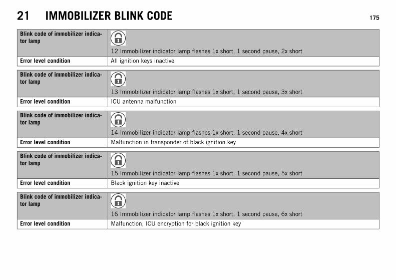
21 IMMOBILIZER BLINK CODE 175
Blink code of immobilizer indica-tor lamp
12 Immobilizer indicator lamp flashes 1x short, 1 second pause, 2x short
Error level condition All ignition keys inactive
Blink code of immobilizer indica-tor lamp
13 Immobilizer indicator lamp flashes 1x short, 1 second pause, 3x short
Error level condition ICU antenna malfunction
Blink code of immobilizer indica-tor lamp
14 Immobilizer indicator lamp flashes 1x short, 1 second pause, 4x short
Error level condition Malfunction in transponder of black ignition key
Blink code of immobilizer indica-tor lamp
15 Immobilizer indicator lamp flashes 1x short, 1 second pause, 5x short
Error level condition Black ignition key inactive
Blink code of immobilizer indica-tor lamp
16 Immobilizer indicator lamp flashes 1x short, 1 second pause, 6x short
Error level condition Malfunction, ICU encryption for black ignition key

21 IMMOBILIZER BLINK CODE 176
Blink code of immobilizer indica-tor lamp
21 Immobilizer indicator lamp flashes 2x short, 1 second pause, 1x short
Error level condition ICU is not activated
Blink code of immobilizer indica-tor lamp
31 Immobilizer indicator lamp flashes 3x short, 1 second pause, 1x short
Error level condition Malfunction, encryption query from EFI control unit to immobilizer control unit
Blink code of immobilizer indica-tor lamp
32 Immobilizer indicator lamp flashes 3x short, 1 second pause, 2x short
Error level condition Malfunction in CAN bus communication
Blink code of immobilizer indica-tor lamp
60 Immobilizer indicator lamp flashes 6x short
Error level condition E²PROM malfunction

22 ENGINE CONTROL BLINK CODE 177
Blink code of FI warninglamp (MIL)
02 FI warning lamp (MIL) flashes 2x short
Error level condition Circuit ignition pulse generator - circuit fault
Blink code of FI warninglamp (MIL)
06 FI warning lamp (MIL) flashes 6x short
Error level condition Throttle valve sensor circuit A - input signal too low
Throttle valve sensor circuit A - input signal too high
Blink code of FI warninglamp (MIL)
07 FI warning lamp (MIL) flashes 7x short
Error level condition Throttle position sensor circuit B - input signal too low
Throttle position sensor circuit B - input signal too high
Blink code of FI warninglamp (MIL)
09 FI warning lamp (MIL) flashes 9x short
Error level condition Manifold absolute pressure sensor cylinder 1 - input signal too low
Manifold absolute pressure sensor cylinder 1 - input signal too high
Blink code of FI warninglamp (MIL)
11 FI warning lamp (MIL) flashes 1x long, 1x short
Error level condition Manifold absolute pressure sensor cylinder 2 - input signal too low
Manifold absolute pressure sensor cylinder 2 - input signal too high
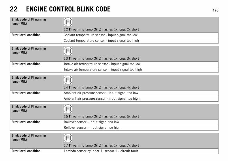
22 ENGINE CONTROL BLINK CODE 178
Blink code of FI warninglamp (MIL)
12 FI warning lamp (MIL) flashes 1x long, 2x short
Error level condition Coolant temperature sensor - input signal too low
Coolant temperature sensor - input signal too high
Blink code of FI warninglamp (MIL)
13 FI warning lamp (MIL) flashes 1x long, 3x short
Error level condition Intake air temperature sensor - input signal too low
Intake air temperature sensor - input signal too high
Blink code of FI warninglamp (MIL)
14 FI warning lamp (MIL) flashes 1x long, 4x short
Error level condition Ambient air pressure sensor - input signal too low
Ambient air pressure sensor - input signal too high
Blink code of FI warninglamp (MIL)
15 FI warning lamp (MIL) flashes 1x long, 5x short
Error level condition Rollover sensor - input signal too low
Rollover sensor - input signal too high
Blink code of FI warninglamp (MIL)
17 FI warning lamp (MIL) flashes 1x long, 7x short
Error level condition Lambda sensor cylinder 1, sensor 1 - circuit fault

22 ENGINE CONTROL BLINK CODE 179
Blink code of FI warninglamp (MIL)
18 FI warning lamp (MIL) flashes 1x long, 8x short
Error level condition Lambda sensor cylinder 2, sensor 1 - circuit fault
Blink code of FI warninglamp (MIL)
24 FI warning lamp (MIL) flashes 2x long, 4x short
Error level condition Power supply - circuit fault
Blink code of FI warninglamp (MIL)
25 FI warning lamp (MIL) flashes 2x long, 5x short
Error level condition Side stand - circuit fault
Blink code of FI warninglamp (MIL)
33 FI warning lamp (MIL) flashes 3x long, 3x short
Error level condition Injector cylinder 1 - circuit fault
Blink code of FI warninglamp (MIL)
34 FI warning lamp (MIL) flashes 3x long, 4x short
Error level condition Injector cylinder 2 - circuit fault

22 ENGINE CONTROL BLINK CODE 180
Blink code of FI warninglamp (MIL)
37 FI warning lamp (MIL) flashes 3x long, 7x short
Error level condition Ignition coil 1, cylinder 1 - circuit fault
Blink code of FI warninglamp (MIL)
38 FI warning lamp (MIL) flashes 3x long, 8x short
Error level condition Ignition coil 1, cylinder 2 - circuit fault
Blink code of FI warninglamp (MIL)
41 FI warning lamp (MIL) flashes 4x long, 1x short
Error level condition Fuel pump control - interruption/short circuit to ground
Fuel pump control - input signal too high
Blink code of FI warninglamp (MIL)
45 FI warning lamp (MIL) flashes 4x long, 5x short
Error level condition Heating lambda sensor cylinder 1, sensor 1 - interruption/short circuit to ground
Heating lambda sensor cylinder 1, sensor 1 - input signal too high
Blink code of FI warninglamp (MIL)
46 FI warning lamp (MIL) flashes 4x long, 6x short
Error level condition Heating lambda sensor cylinder 2, sensor 1 - interruption/short circuit to ground
Heating lambda sensor cylinder 2, sensor 1 - input signal too high

22 ENGINE CONTROL BLINK CODE 181
Blink code of FI warninglamp (MIL)
49 FI warning lamp (MIL) flashes 4x long, 9x short
Error level condition Motor drive circuit A - circuit fault
Blink code of FI warninglamp (MIL)
50 FI warning lamp (MIL) flashes 5x long
Error level condition Motor drive circuit B - circuit fault
Blink code of FI warninglamp (MIL)
54 FI warning lamp (MIL) flashes 5x long, 4x short
Error level condition Secondary air valve - interruption/short circuit to ground
Secondary air valve - input signal too high
Blink code of FI warninglamp (MIL)
68 FI warning lamp (MIL) flashes 6x long, 8x short
Error level condition Manifold absolute pressure sensor cylinder 1 - connection leaks
Blink code of FI warninglamp (MIL)
69 FI warning lamp (MIL) flashes 6x long, 9x short
Error level condition Manifold absolute pressure sensor cylinder 2 - connection leaks

22 ENGINE CONTROL BLINK CODE 182
Blink code of FI warninglamp (MIL)
81 FI warning lamp (MIL) flashes 8x long, 1x short
Error level condition Immobilizer control unit - circuit fault
Blink code of FI warninglamp (MIL)
91 FI warning lamp (MIL) flashes 9x long, 1x short
Error level condition CAN bus communication error

23 TECHNICAL DATA 183
23.1 Engine
Design 2-cylinder 4-stroke Otto motor, 75° V arrangement, water-cooled
Displacement 999 cm³ (60.96 cu in)
Stroke 62.4 mm (2.457 in)
Bore 101 mm (3.98 in)
Compression ratio 11.5:1
Control DOHC, 4 valves per cylinder, chain-driven
Valve - diameter
Exhaust 33 mm (1.3 in)
Intake 38 mm (1.5 in)
Valve clearance
Exhaust at: 20 °C (68 °F) 0.25… 0.30 mm (0.0098… 0.0118 in)
Intake at: 20 °C (68 °F) 0.10… 0.15 mm (0.0039… 0.0059 in)
Crankshaft bearing Sleeve bearing
Conrod bearing Sleeve bearing
Piston Forged light alloy
Piston ring 1 L-ring, 1 tapered compression piston ring, 1 oil scraper ring
Engine lubrication Dry sump lubrication system with two rotor pumps
Primary transmission 35:67
Clutch Multidisc clutch in oil bath/hydraulically activated
Transmission 6-gears, claw-shifted
Transmission ratio
1st gear 12:35
2nd gear 15:32

23 TECHNICAL DATA 184
3rd gear 18:30
4th gear 20:27
5th gear 24:27
6th gear 27:26
Mixture preparation Electronic fuel injection
Ignition system Contactless controlled fully electronic ignition with digital ignitionadjustment
Alternator 12 V, 450 W
Spark plug NGK LKAR8BI9
Spark plug electrode gap 0.8 mm (0.031 in)
Cooling Water cooling, permanent circulation of coolant by water pump
Idle speed 1,400… 1,500 rpm
Cold start device Electric starter
23.2 Engine tightening torques
Screw, damping plate, clutch cover EJOT Altracs M6x10 10 Nm (7.4 lbf ft) Loctite® 243™
Hose clip, intake flange M4 1.5 Nm (1.11 lbf ft) –
Screw, oil spray tube M4 6 Nm (4.4 lbf ft) Loctite® 243™
Remaining engine screws M5 6 Nm (4.4 lbf ft) –
Screw, bearing retainer M5 6 Nm (4.4 lbf ft) Loctite® 243™
Screw, connecting angle on valve cover M5 3 Nm (2.2 lbf ft) Loctite® 243™
Screw, gear sensor M5 3 Nm (2.2 lbf ft) Loctite® 243™
Screw, locking lever M5 6 Nm (4.4 lbf ft) Loctite® 243™
Nut, cylinder head M6 8 Nm (5.9 lbf ft) –

23 TECHNICAL DATA 185
Plug, vacuum connection M6 5 Nm (3.7 lbf ft) Loctite® 243™
Remaining engine screws M6 10 Nm (7.4 lbf ft) –
Screw in alternator cover M6 10 Nm (7.4 lbf ft) –
Screw, bearing bolt in alternator cover M6 10 Nm (7.4 lbf ft) Loctite® 243™
Screw, camshaft bearing support M6 10 Nm (7.4 lbf ft) –
Screw, clutch cover M6 10 Nm (7.4 lbf ft) –
Screw, clutch spring M6 10 Nm (7.4 lbf ft) –
Screw, engine case M6 10 Nm (7.4 lbf ft) –
Screw, freewheel holder M6 10 Nm (7.4 lbf ft) Loctite® 243™
Screw, freewheel hub M6 13 Nm (9.6 lbf ft) Loctite® 648™
Screw, oil pump housing M6 10 Nm (7.4 lbf ft) Loctite® 243™
Screw, pulse generator M6 10 Nm (7.4 lbf ft) Loctite® 243™
Screw, shift drum locating M6 10 Nm (7.4 lbf ft) Loctite® 243™
Screw, shift lever M6 10 Nm (7.4 lbf ft) Loctite® 243™
Screw, starter motor M6 10 Nm (7.4 lbf ft) –
Screw, stator M6 10 Nm (7.4 lbf ft) Loctite® 243™
Screw, valve cover M6 10 Nm (7.4 lbf ft) –
Screw, water pump cover M6 10 Nm (7.4 lbf ft) –
Screw, water pump wheel M6 10 Nm (7.4 lbf ft) Loctite® 243™
Vacuum connection M6 2.5 Nm (1.84 lbf ft) Loctite® 243™
Oil jet M6x0.75 4 Nm (3 lbf ft) Loctite® 243™
Screw, camshaft bearing support M8 Step 110 Nm (7.4 lbf ft)Step 218 Nm (13.3 lbf ft)
–

23 TECHNICAL DATA 186
Screw, clutch cover M8 15 Nm (11.1 lbf ft) –
Screw, cylinder head M8 Step 118 Nm (13.3 lbf ft)Step 223 Nm (17 lbf ft)
Loctite® 243™
Screw, timing chain guide rail M8 15 Nm (11.1 lbf ft) Loctite® 243™
Screw, timing chain tensioning rail M8 20 Nm (14.8 lbf ft) Loctite® 243™
Stud, exhaust flange M8 15 Nm (11.1 lbf ft) –
Nut, cylinder head (exterior) M10 Step 123 Nm (17 lbf ft)Step 234 Nm (25.1 lbf ft)
Only applies when using:Box wrench attachment13 mm (60029081000)
Lubricated with engine oil
Nut, cylinder head on timing chain shaft M10 Step 125 Nm (18.4 lbf ft)Step 238 Nm (28 lbf ft)
Lubricated with engine oil
Plug, clutch lubrication M10 15 Nm (11.1 lbf ft) –
Screw, bearing bolt of timing gears M10 30 Nm (22.1 lbf ft) –
Stud, cylinder head in engine case M10 20 Nm (14.8 lbf ft) –
Oil pressure sensor M10x1 10 Nm (7.4 lbf ft) –
Screw, conrod bearing M10x1 Step 125 Nm (18.4 lbf ft)Step 230 Nm (22.1 lbf ft)Step 360°
–
Spark plug M12x1.25 18 Nm (13.3 lbf ft) –

23 TECHNICAL DATA 187
Engine coolant temperature sensor M12x1.5 12 Nm (8.9 lbf ft) –
Plus, cylinder head (2nd cylinder) M12x1.5 25 Nm (18.4 lbf ft) –
Plug, oil filter housing M14x1.5 15 Nm (11.1 lbf ft) Loctite® 243™
Bleeder flange, alternator cover M16x1.5 10 Nm (7.4 lbf ft) Loctite® 243™
Plug, timing-chain tensioner M16x1.5 20 Nm (14.8 lbf ft) –
Rotor screw M16x1.5 150 Nm (110.6 lbf ft) Loctite® 243™
Nut, balancer shaft M20x1.5 120 Nm (88.5 lbf ft) Loctite® 243™
Nut, engine sprocket M20x1.5 100 Nm (73.8 lbf ft) Loctite® 243™
Screw-in fitting, cooling system M20x1.5 10 Nm (7.4 lbf ft) Loctite® 577™
Nut, inner clutch hub M22x1.5 130 Nm (95.9 lbf ft) Loctite® 243™
Oil drain plug with magnet M22x1.5 35 Nm (25.8 lbf ft) –
Screw in alternator cover M24x1.5 8 Nm (5.9 lbf ft) –
Nut, primary gear M33LHx1.5 130 Nm (95.9 lbf ft) Loctite® 243™
23.3 Capacities
23.3.1 Engine oil
Engine oil 3.0 l (3.2 qt.) External temperature: ≥ 0 °C(≥ 32 °F)
Engine oil (SAE 10W/50)( p. 198)
External temperature: < 0 °C(< 32 °F)
Engine oil (SAE 5W/40)( p. 198)
23.3.2 Coolant
Coolant 2.10 l (2.22 qt.) Coolant ( p. 197)
Coolant (mixed ready to use) ( p. 197)

23 TECHNICAL DATA 188
23.3.3 Fuel
Total fuel tank capacity, approx. 15 l (4 US gal) Super unleaded (ROZ 95/RON 95/PON 91) ( p. 199)
Fuel reserve, approx. 3.5 l (3.7 qt.)
23.4 Chassis
Frame Lattice frame made of chrome molybdenum steel tubing, powder-coated
Fork WP Suspension Up Side Down 4860 ROMA PA
Shock absorber WP Suspension 4618 BAVP DCC
Suspension travel
Front 160 mm (6.3 in)
Rear 180 mm (7.09 in)
Brake system
Front Double disc brake with radially screwed four-piston brake calipers,float-mounted brake discs
Rear Single disc brake with dual-piston brake caliper, rigid-mountedbrake disc
Brake system Two independent brake circuits with ABS (antilock brake system) -Brembo/Bosch
Brake discs - diameter
Front 305 mm (12.01 in)
Rear 240 mm (9.45 in)
Brake discs - wear limit
Front 4.5 mm (0.177 in)

23 TECHNICAL DATA 189
Brake disc - wear limit
Rear 4.5 mm (0.177 in)
Tire air pressure, solo
Front 2.4 bar (35 psi)
Rear 2.4 bar (35 psi)
Tire air pressure with passenger/full payload
Front 2.4 bar (35 psi)
Rear 2.6 bar (38 psi)
Secondary drive ratio 17:41
Chain 5/8 x 5/16” X‑ring
Steering head angle 65.6°
Wheelbase 1,505±15 mm (59.25±0.59 in)
Seat height, unloaded 875 mm (34.45 in)
Ground clearance, unloaded 195 mm (7.68 in)
Weight without fuel, approx. 192 kg (423 lb.)
Maximum permissible front axle load 160 kg (353 lb.)
Maximum permissible rear axle load 250 kg (551 lb.)
Maximum permissible total weight 400 kg (882 lb.)
23.5 Electrical system
Battery YTZ14S Battery voltage: 12 VNominal capacity: 11.2 Ahmaintenance-free
Fuse 75011088010 10 A
Fuse 75011088015 15 A
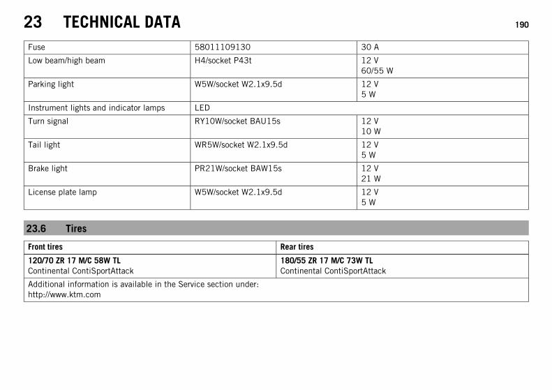
23 TECHNICAL DATA 190
Fuse 58011109130 30 A
Low beam/high beam H4/socket P43t 12 V60/55 W
Parking light W5W/socket W2.1x9.5d 12 V5 W
Instrument lights and indicator lamps LED
Turn signal RY10W/socket BAU15s 12 V10 W
Tail light WR5W/socket W2.1x9.5d 12 V5 W
Brake light PR21W/socket BAW15s 12 V21 W
License plate lamp W5W/socket W2.1x9.5d 12 V5 W
23.6 Tires
Front tires Rear tires
120/70 ZR 17 M/C 58W TLContinental ContiSportAttack
180/55 ZR 17 M/C 73W TLContinental ContiSportAttack
Additional information is available in the Service section under:http://www.ktm.com

23 TECHNICAL DATA 191
23.7 Fork
Fork part number 14.18.7L.21
Fork WP Suspension Up Side Down 4860 ROMA PA
Compression damping
Comfort 20 clicks
Standard 15 clicks
Sport 10 clicks
Full payload 10 clicks
Rebound damping
Comfort 20 clicks
Standard 15 clicks
Sport 10 clicks
Full payload 10 clicks
Spring preload - Preload Adjuster
Comfort 5 turns
Standard 5 turns
Sport 7 turns
Full payload 7 turns
Spring length with preload spacer(s) 386 mm (15.2 in)
Spring rate
Medium (standard) 7.5 N/mm (42.8 lb/in)
Fork length 877 mm (34.53 in)
Air chamber length 100±20 mm (3.94±0.79 in)
Fork oil per fork leg 732 ml (24.75 fl. oz.) Fork oil (SAE 4) (48601166S1) ( p. 199)

23 TECHNICAL DATA 192
23.8 Shock absorber
Shock absorber part number 15.18.7L.21
Shock absorber WP Suspension 4618 BAVP DCC
Compression damping, low-speed
Comfort 25 clicks
Standard 20 clicks
Sport 15 clicks
Full payload 15 clicks
Compression damping, high-speed
Comfort 2 turns
Standard 1.5 turns
Sport 1 turn
Full payload 1 turn
Rebound damping
Comfort 20 clicks
Standard 15 clicks
Sport 10 clicks
Full payload 10 clicks
Spring preload
Comfort 11 mm (0.43 in)
Standard 11 mm (0.43 in)
Sport 11 mm (0.43 in)
Full payload 13 mm (0.51 in)
Spring rate

23 TECHNICAL DATA 193
Medium (standard) 140 N/mm (799 lb/in)
Spring length 200 mm (7.87 in)
Gas pressure 10 bar (145 psi)
Static sag 20 mm (0.79 in)
Fitted length 372 mm (14.65 in)
Shock absorber fluid Shock absorber oil (SAE 2.5) (50180342S1) ( p. 199)
23.9 Chassis tightening torques
Remaining frame bolts EJOT Delta PT 50x12 1.2 Nm (0.89 lbf ft) –
Remaining frame bolts EJOT PT K50x12 T20 1.2 Nm (0.89 lbf ft) –
Remaining frame bolts EJOT PT K50x18 T20 2 Nm (1.5 lbf ft) –
Screw, brake line holder EJOT PT K60x20 2 Nm (1.5 lbf ft) –
Screw, chain sliding piece EJOT PT K60x20 2 Nm (1.5 lbf ft) –
Screw, combination instrument EJOT Delta PT 45x12 1 Nm (0.7 lbf ft) –
Screw, side stand switch M4 2 Nm (1.5 lbf ft) Loctite® 243™
Remaining chassis nuts M5 5 Nm (3.7 lbf ft) –
Remaining chassis screws M5 5 Nm (3.7 lbf ft) –
Screw, brake line holder M5 2 Nm (1.5 lbf ft) –
Screw, chain sliding guard M5 5 Nm (3.7 lbf ft) –
Screw, closure flange, fuel tank M5 3.3 Nm (2.43 lbf ft) –
Screw, engine oil level viewer M5 3.3 Nm (2.43 lbf ft) –
Screw, foot brake lever stub M5 6 Nm (4.4 lbf ft) Loctite® 243™
Nut, tail light M6 8 Nm (5.9 lbf ft) –
Remaining chassis nuts M6 10 Nm (7.4 lbf ft) –

23 TECHNICAL DATA 194
Remaining chassis screws M6 10 Nm (7.4 lbf ft) –
Screw, chain sliding guard M6 6 Nm (4.4 lbf ft) Loctite® 243™
Screw, foot brake cylinder M6 10 Nm (7.4 lbf ft) Loctite® 243™
Screw, fuel pump M6 6 Nm (4.4 lbf ft) –
Screw, fuel tap M6 6 Nm (4.4 lbf ft) –
Screw, holder on ABS unit M6 6 Nm (4.4 lbf ft) –
Screw, magnetic holder on side stand M6 6 Nm (4.4 lbf ft) Loctite® 243™
Screw, seat bracket, fuel tank M6 3.3 Nm (2.43 lbf ft) –
Screw, splash protector M6 6 Nm (4.4 lbf ft) Loctite® 243™
Screw, spoiler M6 3.3 Nm (2.43 lbf ft) –
Screw, wheel speed sensor M6 6 Nm (4.4 lbf ft) Loctite® 243™
Nut, manifold on cylinder head M8 Tightening sequence:Tighten the nuts uniformly.Do not bend the metal.
–
Remaining chassis nuts M8 25 Nm (18.4 lbf ft) –
Remaining chassis screws M8 25 Nm (18.4 lbf ft) –
Screw, bottom triple clamp M8 15 Nm (11.1 lbf ft) –
Screw, exhaust clamp on distributorpipe
M8 35 Nm (25.8 lbf ft) –
Screw, exhaust clamp on main silencer M8 20 Nm (14.8 lbf ft) –
Screw, fork stub M8 15 Nm (11.1 lbf ft) –
Screw, front brake disc M8 30 Nm (22.1 lbf ft) Loctite® 243™
Screw, handlebar clamp M8 20 Nm (14.8 lbf ft) –
Screw, handrail M8 20 Nm (14.8 lbf ft) –
Screw, ignition lock (ratchet screw) M8 Loctite® 243™

23 TECHNICAL DATA 195
Screw, rear brake disc M8 30 Nm (22.1 lbf ft) Loctite® 243™
Screw, rear footrest bracket M8 25 Nm (18.4 lbf ft) Loctite® 243™
Screw, spring holder on side standbracket
M8 25 Nm (18.4 lbf ft) Loctite® 243™
Screw, steering stem M8 20 Nm (14.8 lbf ft) –
Screw, top triple clamp M8 20 Nm (14.8 lbf ft) –
Remaining chassis nuts M10 45 Nm (33.2 lbf ft) –
Remaining frame bolts M10 45 Nm (33.2 lbf ft) –
Screw connection, engine mountingbracket
M10 45 Nm (33.2 lbf ft) –
Screw, handlebar support M10 20 Nm (14.8 lbf ft) –
Screw, side stand M10 35 Nm (25.8 lbf ft) Loctite® 243™
Screw, side stand bracket M10 45 Nm (33.2 lbf ft) Loctite® 243™
Banjo bolt, brake line M10x1 20 Nm (14.8 lbf ft) –
Brake light switch M10x1 20 Nm (14.8 lbf ft) –
Screw connection, rear hub shockabsorber/rear sprocket
M10x1.25 50 Nm (36.9 lbf ft) Loctite® 243™
Screw, front brake caliper M10x1.25 45 Nm (33.2 lbf ft) Loctite® 243™
Screw, lower subframe M10x1.25 45 Nm (33.2 lbf ft) Loctite® 243™
Screw, upper subframe M10x1.25 45 Nm (33.2 lbf ft) Loctite® 243™
Oil drain plug with magnet M12x1.5 25 Nm (18.4 lbf ft) –
Screw connection, suction line M14x1.5 45 Nm (33.2 lbf ft) Loctite® 577™
Screw, bottom shock absorber M14x1.5 80 Nm (59 lbf ft) Thread greased
Screw, top shock absorber M14x1.5 80 Nm (59 lbf ft) Thread greased
Nut, oil line M16x1.5 25 Nm (18.4 lbf ft) –

23 TECHNICAL DATA 196
Nut, swingarm pivot M19x1.5 130 Nm (95.9 lbf ft) Thread greased
Screw, steering head M20x1.5 12 Nm (8.9 lbf ft) –
Bolt, front axle M25x1.5 45 Nm (33.2 lbf ft) –
Nut, rear wheel spindle M25x1.5 90 Nm (66.4 lbf ft) Thread greased
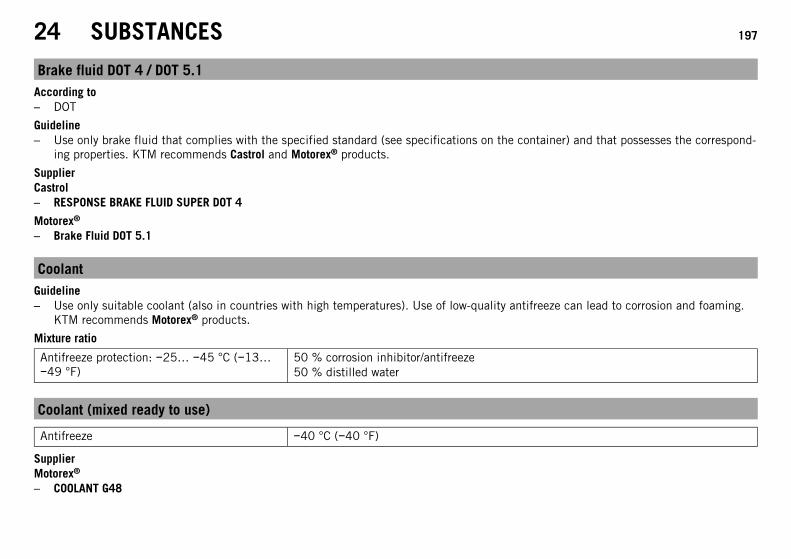
24 SUBSTANCES 197
Brake fluid DOT 4 / DOT 5.1According to– DOT
Guideline– Use only brake fluid that complies with the specified standard (see specifications on the container) and that possesses the correspond-
ing properties. KTM recommends Castrol and Motorex® products.
SupplierCastrol– RESPONSE BRAKE FLUID SUPER DOT 4
Motorex®
– Brake Fluid DOT 5.1
CoolantGuideline– Use only suitable coolant (also in countries with high temperatures). Use of low-quality antifreeze can lead to corrosion and foaming.
KTM recommends Motorex® products.
Mixture ratio
Antifreeze protection: −25… −45 °C (−13…−49 °F)
50 % corrosion inhibitor/antifreeze50 % distilled water
Coolant (mixed ready to use)
Antifreeze −40 °C (−40 °F)
SupplierMotorex®
– COOLANT G48

24 SUBSTANCES 198
Engine oil (SAE 10W/50)According to– JASO T903 MA ( p. 204)
– SAE ( p. 204) (SAE 10W/50)
Guideline– Use only engine oils that comply with the specified standards (see specifications on the container) and that possess the corresponding
properties. KTM recommends Motorex® products.
Fully synthetic engine oil
SupplierMotorex®
– Power Synt 4T
Engine oil (SAE 5W/40)According to– JASO T903 MA ( p. 204)
– SAE ( p. 204) (SAE 5W/40)
Guideline– Use only engine oils that comply with the specified standards (see specifications on the container) and that possess the corresponding
properties. KTM recommends Motorex® products.
Synthetic engine oil
SupplierMotorex®
– Power Synt 4T

24 SUBSTANCES 199
Fork oil (SAE 4) (48601166S1)According to– SAE ( p. 204) (SAE 4)
Guideline– Use only oils that comply with the specified standards (see specifications on the container) and that possess the corresponding proper-
ties.
Hydraulic fluid (15)According to– ISO VG (15)
Guideline– Use only hydraulic oil that complies with the specified standard (see specifications on the container) and that possesses the corre-
sponding properties. KTM recommends Motorex® products.
SupplierMotorex®
– Hydraulic Fluid 75
Shock absorber oil (SAE 2.5) (50180342S1)According to– SAE ( p. 204) (SAE 2.5)
Guideline– Use only oils that comply with the specified standards (see specifications on the container) and that possess the corresponding proper-
ties.
Super unleaded (ROZ 95/RON 95/PON 91)According to– DIN EN 228 (ROZ 95/RON 95/PON 91)

24 SUBSTANCES 200
Guideline– Only use unleaded super fuel that matches or is equivalent to the specified fuel grade.
– Fuel with an ethanol content of up to 10 % (E10 fuel) is safe to use.
InfoDo not use fuel containing methanol (e. g. M15, M85, M100) or more than 10 % ethanol (e. g. E15, E25, E85, E100).

25 AUXILIARY SUBSTANCES 201
Chain cleanerGuideline– KTM recommends Motorex® products.
SupplierMotorex®
– Chain Clean
Chain lube for road useGuideline– KTM recommends Motorex® products.
SupplierMotorex®
– Chainlube Road
Cleaning and preserving materials for metal, rubber and plasticGuideline– KTM recommends Motorex® products.
SupplierMotorex®
– Protect & Shine
Fuel additiveGuideline– KTM recommends Motorex® products.
SupplierMotorex®
– Fuel Stabilizer

25 AUXILIARY SUBSTANCES 202
High-luster polish for paintGuideline– KTM recommends Motorex® products.
SupplierMotorex®
– Moto Polish
Long-life greaseGuideline– KTM recommends Motorex® products.
SupplierMotorex®
– Bike Grease 2000
Motorcycle cleanerGuideline– KTM recommends Motorex® products.
SupplierMotorex®
– Moto Clean 900
Paint cleaner and polish for high-gloss and matte finishes, bare metal and plastic surfacesGuideline– KTM recommends Motorex® products.
SupplierMotorex®
– Clean & Polish

25 AUXILIARY SUBSTANCES 203
Universal oil sprayGuideline– KTM recommends Motorex® products.
SupplierMotorex®
– Joker 440 Synthetic

26 STANDARDS 204
JASO T903 MADifferent technical development directions required a new specification for 4-stroke motorcycles – the JASO T903 MA Standard. Ear-lier, engine oils from the automobile industry were used for 4-stroke motorcycles because there was no separate motorcycle specification.Whereas long service intervals are demanded for automobile engines, high performance at high engine speeds are in the foreground formotorcycle engines. In most motorcycles, the gearbox and the clutch are lubricated with the same oil as the engine. The JASO MA Stan-dard meets these special requirements.
SAEThe SAE viscosity classes were defined by the Society of Automotive Engineers and are used for classifying oils according to their viscos-ity. The viscosity describes only one property of oil and says nothing about quality.

INDEX 205
INDEX
A
ABS . . . . . . . . . . . . . . . . . . . . . . . . . . . . . . . . . . . . . . . . . 89Accessories . . . . . . . . . . . . . . . . . . . . . . . . . . . . . . . . . . . . 13
Antifreezechecking . . . . . . . . . . . . . . . . . . . . . . . . . . . . . . . . . . 144
Antilock brake system . . . . . . . . . . . . . . . . . . . . . . . . . . . . . 89
B
Baggage . . . . . . . . . . . . . . . . . . . . . . . . . . . . . . . . . . . . . . 46
Batteryinstalling . . . . . . . . . . . . . . . . . . . . . . . . . . . . . . . . . . 114recharging . . . . . . . . . . . . . . . . . . . . . . . . . . . . . . . . . 115removing . . . . . . . . . . . . . . . . . . . . . . . . . . . . . . . . . . 112
Blink codeengine control . . . . . . . . . . . . . . . . . . . . . . . . . . 177-182immobilizer . . . . . . . . . . . . . . . . . . . . . . . . . . . . 175-176
Brake disc, rearchecking . . . . . . . . . . . . . . . . . . . . . . . . . . . . . . . . . . . 96
Brake discs, frontchecking . . . . . . . . . . . . . . . . . . . . . . . . . . . . . . . . . . . 90
Brake fluidfront brake, adding . . . . . . . . . . . . . . . . . . . . . . . . . . . . 92rear brake, adding . . . . . . . . . . . . . . . . . . . . . . . . . . . . 97
Brake fluid levelfront brake, checking . . . . . . . . . . . . . . . . . . . . . . . . . . 91rear brake, checking . . . . . . . . . . . . . . . . . . . . . . . . . . . 96
Brake light bulbchanging . . . . . . . . . . . . . . . . . . . . . . . . . . . . . . . . . . 128
Brake liningsfront brake, checking . . . . . . . . . . . . . . . . . . . . . . . . . . 93rear brake, checking . . . . . . . . . . . . . . . . . . . . . . . . . . . 99
Brakes . . . . . . . . . . . . . . . . . . . . . . . . . . . . . . . . . . . . . . . 55Braking . . . . . . . . . . . . . . . . . . . . . . . . . . . . . . . . . . . . . . 55
C
Chainchecking . . . . . . . . . . . . . . . . . . . . . . . . . . . . . . . . . . . 84cleaning . . . . . . . . . . . . . . . . . . . . . . . . . . . . . . . . . . . 80dirt, checking . . . . . . . . . . . . . . . . . . . . . . . . . . . . . . . . 80
Chain guidechecking . . . . . . . . . . . . . . . . . . . . . . . . . . . . . . . . . . . 84
Chain tensionadjusting . . . . . . . . . . . . . . . . . . . . . . . . . . . . . . . . . . . 82checking . . . . . . . . . . . . . . . . . . . . . . . . . . . . . . . . . . . 81
Chassis number . . . . . . . . . . . . . . . . . . . . . . . . . . . . . . . . . 20
Clutchfluid level, checking/correcting . . . . . . . . . . . . . . . . . . . . 87
Clutch lever . . . . . . . . . . . . . . . . . . . . . . . . . . . . . . . . . . . 23basic position, adjusting . . . . . . . . . . . . . . . . . . . . . . . . 87
Combination instrumentclock, setting . . . . . . . . . . . . . . . . . . . . . . . . . . . . . . . . 33coolant temperature indicator . . . . . . . . . . . . . . . . . . . . . 38display . . . . . . . . . . . . . . . . . . . . . . . . . . . . . . . . . . . . 31

INDEX 206
display, ambient temperature . . . . . . . . . . . . . . . . . . . . . 36function buttons . . . . . . . . . . . . . . . . . . . . . . . . . . . . . . 29indicator lamps . . . . . . . . . . . . . . . . . . . . . . . . . . . . . . 30kilometers or miles, setting . . . . . . . . . . . . . . . . . . . . . . 32ODO display . . . . . . . . . . . . . . . . . . . . . . . . . . . . . . . . . 34Overview . . . . . . . . . . . . . . . . . . . . . . . . . . . . . . . . . . . 28speed display . . . . . . . . . . . . . . . . . . . . . . . . . . . . . . . . 32tachometer . . . . . . . . . . . . . . . . . . . . . . . . . . . . . . . . . 29temperature units, setting . . . . . . . . . . . . . . . . . . . . . . . 36time . . . . . . . . . . . . . . . . . . . . . . . . . . . . . . . . . . . . . . 33TRIP 1 display, setting/resetting . . . . . . . . . . . . . . . . . . . 34TRIP 2 display, setting/resetting . . . . . . . . . . . . . . . . . . . 35TRIP F display . . . . . . . . . . . . . . . . . . . . . . . . . . . . . . . . 36warning of slippery roads . . . . . . . . . . . . . . . . . . . . . . . . 37
Coolantdraining . . . . . . . . . . . . . . . . . . . . . . . . . . . . . . . . . . 148
Coolant levelchecking . . . . . . . . . . . . . . . . . . . . . . . . . . . . . . . . . . 144compensating tank, checking . . . . . . . . . . . . . . . . . . . . 147
Cooling system . . . . . . . . . . . . . . . . . . . . . . . . . . . . . . . . 144filling/bleeding . . . . . . . . . . . . . . . . . . . . . . . . . . . . . . 149
Customer service . . . . . . . . . . . . . . . . . . . . . . . . . . . . . . . . 14
E
Electric starter button . . . . . . . . . . . . . . . . . . . . . . . . . . . . . 27Emergency OFF switch . . . . . . . . . . . . . . . . . . . . . . . . . . . . . 26
Enginerunning in . . . . . . . . . . . . . . . . . . . . . . . . . . . . . . . . . . 46
Engine number . . . . . . . . . . . . . . . . . . . . . . . . . . . . . . . . . . 21
Engine oiladding . . . . . . . . . . . . . . . . . . . . . . . . . . . . . . . . . . . 164changing . . . . . . . . . . . . . . . . . . . . . . . . . . . . . . . . . . 158draining . . . . . . . . . . . . . . . . . . . . . . . . . . . . . . . . . . 158refilling . . . . . . . . . . . . . . . . . . . . . . . . . . . . . . . . . . . 163
Engine oil levelchecking . . . . . . . . . . . . . . . . . . . . . . . . . . . . . . . . . . 157
Engine sprocketchecking . . . . . . . . . . . . . . . . . . . . . . . . . . . . . . . . . . . 84
Environment . . . . . . . . . . . . . . . . . . . . . . . . . . . . . . . . . . . . 11
F
Figures . . . . . . . . . . . . . . . . . . . . . . . . . . . . . . . . . . . . . . . 14
Filler capclosing . . . . . . . . . . . . . . . . . . . . . . . . . . . . . . . . . . . . 39opening . . . . . . . . . . . . . . . . . . . . . . . . . . . . . . . . . . . . 38
Foot brake lever . . . . . . . . . . . . . . . . . . . . . . . . . . . . . . . . 43basic position, adjusting . . . . . . . . . . . . . . . . . . . . . . . . 95free travel, checking . . . . . . . . . . . . . . . . . . . . . . . . . . . 94
Fork . . . . . . . . . . . . . . . . . . . . . . . . . . . . . . . . . . . . . . . . 64compression damping, adjusting . . . . . . . . . . . . . . . . . . . 64fork legs, bleeding . . . . . . . . . . . . . . . . . . . . . . . . . . . . 75rebound, adjusting . . . . . . . . . . . . . . . . . . . . . . . . . . . . 65spring preload, adjusting . . . . . . . . . . . . . . . . . . . . . . . . 66
Fork part number . . . . . . . . . . . . . . . . . . . . . . . . . . . . . . . . 22

INDEX 207
Front wheelinstalling . . . . . . . . . . . . . . . . . . . . . . . . . . . . . . . . . . 102removing . . . . . . . . . . . . . . . . . . . . . . . . . . . . . . . . . . 101
Fuel tankpositioning . . . . . . . . . . . . . . . . . . . . . . . . . . . . . . . . . 77reinstalling . . . . . . . . . . . . . . . . . . . . . . . . . . . . . . . . . 76
Fuseindividual power consumers, changing . . . . . . . . . . . . . . 120
Fuses, ABSchanging . . . . . . . . . . . . . . . . . . . . . . . . . . . . . . . . . . 119
H
Hand brake lever . . . . . . . . . . . . . . . . . . . . . . . . . . . . . . . 23basic position, adjusting . . . . . . . . . . . . . . . . . . . . . . . . 90
Handrails . . . . . . . . . . . . . . . . . . . . . . . . . . . . . . . . . . . . . 41
Headlightheadlight range, adjusting . . . . . . . . . . . . . . . . . . . . . . 138
Headlight adjustmentchecking . . . . . . . . . . . . . . . . . . . . . . . . . . . . . . . . . . 138
Headlight bulbchanging . . . . . . . . . . . . . . . . . . . . . . . . . . . . . . . . . . 122
Headlight flasher switch . . . . . . . . . . . . . . . . . . . . . . . . . . . . 25
Helmet lock . . . . . . . . . . . . . . . . . . . . . . . . . . . . . . . . . . . 41mounting on vehicle . . . . . . . . . . . . . . . . . . . . . . . . . . . 79
Horn button . . . . . . . . . . . . . . . . . . . . . . . . . . . . . . . . . . . . 24
I
Ignition curveadjusting to fuel quality . . . . . . . . . . . . . . . . . . . . . . . . 154plug-in connection . . . . . . . . . . . . . . . . . . . . . . . . . . . 153
Ignition keyactivating/deactivating . . . . . . . . . . . . . . . . . . . . . . . . . 139
Ignition lock . . . . . . . . . . . . . . . . . . . . . . . . . . . . . . . . . . . 27Immobilizer . . . . . . . . . . . . . . . . . . . . . . . . . . . . . . . . . . . . 28Indicator lamps . . . . . . . . . . . . . . . . . . . . . . . . . . . . . . . . . 30Intended use . . . . . . . . . . . . . . . . . . . . . . . . . . . . . . . . . . . . 8
K
Key number . . . . . . . . . . . . . . . . . . . . . . . . . . . . . . . . . . . . 21
L
License plate lampchanging . . . . . . . . . . . . . . . . . . . . . . . . . . . . . . . . . . 136
Light switch . . . . . . . . . . . . . . . . . . . . . . . . . . . . . . . . . . . . 25
M
Main fusechanging . . . . . . . . . . . . . . . . . . . . . . . . . . . . . . . . . . 117
Motorcyclecleaning . . . . . . . . . . . . . . . . . . . . . . . . . . . . . . . . . . 165raising with the front wheel stand . . . . . . . . . . . . . . . . . . 74raising with the rear wheel stand . . . . . . . . . . . . . . . . . . . 73taking off of the front wheel stand . . . . . . . . . . . . . . . . . . 74taking off of the rear wheel stand . . . . . . . . . . . . . . . . . . 73

INDEX 208
O
Oil filterchanging . . . . . . . . . . . . . . . . . . . . . . . . . . . . . . . . . . 158
Oil screenscleaning . . . . . . . . . . . . . . . . . . . . . . . . . . . . . . . . . . 158
Operating substances . . . . . . . . . . . . . . . . . . . . . . . . . . . . . . 13Owner's Manual . . . . . . . . . . . . . . . . . . . . . . . . . . . . . . . . . 12
P
Parking . . . . . . . . . . . . . . . . . . . . . . . . . . . . . . . . . . . . . . 57
Parking light bulbchanging . . . . . . . . . . . . . . . . . . . . . . . . . . . . . . . . . . 125
Passenger footrests . . . . . . . . . . . . . . . . . . . . . . . . . . . . . . . 42
Play in throttle cableadjusting . . . . . . . . . . . . . . . . . . . . . . . . . . . . . . . . . . 153checking . . . . . . . . . . . . . . . . . . . . . . . . . . . . . . . . . . 152
Preparing for useafter storage . . . . . . . . . . . . . . . . . . . . . . . . . . . . . . . 171checks and maintenance measures when preparing for use . 49information on first use . . . . . . . . . . . . . . . . . . . . . . . . . 45
Protective clothing . . . . . . . . . . . . . . . . . . . . . . . . . . . . . . . 11
R
Rear hub rubber damperschecking . . . . . . . . . . . . . . . . . . . . . . . . . . . . . . . . . . 108
Rear sprocketchecking . . . . . . . . . . . . . . . . . . . . . . . . . . . . . . . . . . . 84
Rear wheelinstalling . . . . . . . . . . . . . . . . . . . . . . . . . . . . . . . . . . 106removing . . . . . . . . . . . . . . . . . . . . . . . . . . . . . . . . . . 104
Refuelingfuel . . . . . . . . . . . . . . . . . . . . . . . . . . . . . . . . . . . . . . 59
Riding . . . . . . . . . . . . . . . . . . . . . . . . . . . . . . . . . . . . . . 52starting off . . . . . . . . . . . . . . . . . . . . . . . . . . . . . . . . . 52
S
Safe operation . . . . . . . . . . . . . . . . . . . . . . . . . . . . . . . . . . 10
Seatmounting . . . . . . . . . . . . . . . . . . . . . . . . . . . . . . . . . . 76removing . . . . . . . . . . . . . . . . . . . . . . . . . . . . . . . . . . . 75
Seat lock . . . . . . . . . . . . . . . . . . . . . . . . . . . . . . . . . . . . . 40Service . . . . . . . . . . . . . . . . . . . . . . . . . . . . . . . . . . . . . . . 13Service schedule . . . . . . . . . . . . . . . . . . . . . . . . . . . . . 61-63
Shift lever . . . . . . . . . . . . . . . . . . . . . . . . . . . . . . . . . . . . 42basic position, adjusting . . . . . . . . . . . . . . . . . . . . . . . 155basic position, checking . . . . . . . . . . . . . . . . . . . . . . . 155
Shifting . . . . . . . . . . . . . . . . . . . . . . . . . . . . . . . . . . . . . . 52
Shock absorber . . . . . . . . . . . . . . . . . . . . . . . . . . . . . . . . 64compression damping, general . . . . . . . . . . . . . . . . . . . . 68compression damping, high-speed, adjusting . . . . . . . . . . 69compression damping, low-speed, adjusting . . . . . . . . . . . 68rebound damping, adjusting . . . . . . . . . . . . . . . . . . . . . . 70spring preload, adjusting . . . . . . . . . . . . . . . . . . . . . . . . 71
Shock absorber part number . . . . . . . . . . . . . . . . . . . . . . . . . 22

INDEX 209
Side stand . . . . . . . . . . . . . . . . . . . . . . . . . . . . . . . . . . . . . 44Spare parts . . . . . . . . . . . . . . . . . . . . . . . . . . . . . . . . . . . . 13Starting . . . . . . . . . . . . . . . . . . . . . . . . . . . . . . . . . . . . . . 50Steering lock . . . . . . . . . . . . . . . . . . . . . . . . . . . . . . . . . . . 27Stopping . . . . . . . . . . . . . . . . . . . . . . . . . . . . . . . . . . . . . . 57Storage . . . . . . . . . . . . . . . . . . . . . . . . . . . . . . . . . . . . . 169
T
Tail lamp bulbschanging . . . . . . . . . . . . . . . . . . . . . . . . . . . . . . . . . . 132
Technical datacapacities . . . . . . . . . . . . . . . . . . . . . . . . . . . . . . . . . 187chassis . . . . . . . . . . . . . . . . . . . . . . . . . . . . . . . . . . . 188chassis tightening torques . . . . . . . . . . . . . . . . . . . . . . 193electrical system . . . . . . . . . . . . . . . . . . . . . . . . . . . . 189engine . . . . . . . . . . . . . . . . . . . . . . . . . . . . . . . . . . . 183engine tightening torques . . . . . . . . . . . . . . . . . . . . . . 184fork . . . . . . . . . . . . . . . . . . . . . . . . . . . . . . . . . . . . . 191shock absorber . . . . . . . . . . . . . . . . . . . . . . . . . . . . . . 192tires . . . . . . . . . . . . . . . . . . . . . . . . . . . . . . . . . . . . . 190
Throttle grip . . . . . . . . . . . . . . . . . . . . . . . . . . . . . . . . . . . . 24
Tire air pressurechecking . . . . . . . . . . . . . . . . . . . . . . . . . . . . . . . . . . 110
Tire conditionchecking . . . . . . . . . . . . . . . . . . . . . . . . . . . . . . . . . . 109
Tool set . . . . . . . . . . . . . . . . . . . . . . . . . . . . . . . . . . . . . . 40Transport . . . . . . . . . . . . . . . . . . . . . . . . . . . . . . . . . . . . . 58Troubleshooting . . . . . . . . . . . . . . . . . . . . . . . . . . . . 172-174
Turn signal bulbchanging . . . . . . . . . . . . . . . . . . . . . . . . . . . . . . . . . . 127
Turn signal switch . . . . . . . . . . . . . . . . . . . . . . . . . . . . . . . . 26Type label . . . . . . . . . . . . . . . . . . . . . . . . . . . . . . . . . . . . . 20
U
Use definition . . . . . . . . . . . . . . . . . . . . . . . . . . . . . . . . . . . 8
V
Vehicleloading . . . . . . . . . . . . . . . . . . . . . . . . . . . . . . . . . . . . 46
View of vehiclefront left . . . . . . . . . . . . . . . . . . . . . . . . . . . . . . . . . . . 16rear right . . . . . . . . . . . . . . . . . . . . . . . . . . . . . . . . . . . 18
W
Warning of slippery roads . . . . . . . . . . . . . . . . . . . . . . . . . . . 37Warranty . . . . . . . . . . . . . . . . . . . . . . . . . . . . . . . . . . . . . . 13
Winter operationchecks and maintenance measures . . . . . . . . . . . . . . . . 167
Work rules . . . . . . . . . . . . . . . . . . . . . . . . . . . . . . . . . . . . 11

*3211959en*3211959en
11/2012
KTM-Sportmotorcycle AG5230 Mattighofen/Austriahttp://www.ktm.com
Photo: Mitterbauer/KTM