AXIS M11-E Series - User Manual
54
AXIS M11-E Series AXIS M1135-E Network camera AXIS M1137-E Network camera User Manual
-
Upload
khangminh22 -
Category
Documents
-
view
0 -
download
0
Transcript of AXIS M11-E Series - User Manual

AXIS M11-E Series
AXIS M1135-E Network camera
AXIS M1137-E Network camera
User Manual

AXIS M11-E Series
Table of Contents
About this manual . . . . . . . . . . . . . . . . . . . . . . . . . . . . . . . . . . . . . . . . . . 3Installation . . . . . . . . . . . . . . . . . . . . . . . . . . . . . . . . . . . . . . . . . . . . . . . . 4Get started . . . . . . . . . . . . . . . . . . . . . . . . . . . . . . . . . . . . . . . . . . . . . . . . 5
Find the device on the network . . . . . . . . . . . . . . . . . . . . . . . . . . . . . . . . . . . . 5Open the device's webpage . . . . . . . . . . . . . . . . . . . . . . . . . . . . . . . . . . . . . . . 5Webpage overview . . . . . . . . . . . . . . . . . . . . . . . . . . . . . . . . . . . . . . . . . . . . . . 6
Configure your device . . . . . . . . . . . . . . . . . . . . . . . . . . . . . . . . . . . . . . . . 7Adjust the image . . . . . . . . . . . . . . . . . . . . . . . . . . . . . . . . . . . . . . . . . . . . . . . . 7View and record video . . . . . . . . . . . . . . . . . . . . . . . . . . . . . . . . . . . . . . . . . . . . 11Set up rules for events . . . . . . . . . . . . . . . . . . . . . . . . . . . . . . . . . . . . . . . . . . . 12
The device interface . . . . . . . . . . . . . . . . . . . . . . . . . . . . . . . . . . . . . . . . . 15Status . . . . . . . . . . . . . . . . . . . . . . . . . . . . . . . . . . . . . . . . . . . . . . . . . . . . . . . . 15Video . . . . . . . . . . . . . . . . . . . . . . . . . . . . . . . . . . . . . . . . . . . . . . . . . . . . . . . . . 15Audio . . . . . . . . . . . . . . . . . . . . . . . . . . . . . . . . . . . . . . . . . . . . . . . . . . . . . . . . . 25Recordings . . . . . . . . . . . . . . . . . . . . . . . . . . . . . . . . . . . . . . . . . . . . . . . . . . . . . 26Apps . . . . . . . . . . . . . . . . . . . . . . . . . . . . . . . . . . . . . . . . . . . . . . . . . . . . . . . . . . 26System . . . . . . . . . . . . . . . . . . . . . . . . . . . . . . . . . . . . . . . . . . . . . . . . . . . . . . . . 27Maintenance . . . . . . . . . . . . . . . . . . . . . . . . . . . . . . . . . . . . . . . . . . . . . . . . . . . 40
Learn more . . . . . . . . . . . . . . . . . . . . . . . . . . . . . . . . . . . . . . . . . . . . . . . . 42Bitrate control . . . . . . . . . . . . . . . . . . . . . . . . . . . . . . . . . . . . . . . . . . . . . . . . . . 42View area . . . . . . . . . . . . . . . . . . . . . . . . . . . . . . . . . . . . . . . . . . . . . . . . . . . . . . 43Privacy masks . . . . . . . . . . . . . . . . . . . . . . . . . . . . . . . . . . . . . . . . . . . . . . . . . . 43Overlays . . . . . . . . . . . . . . . . . . . . . . . . . . . . . . . . . . . . . . . . . . . . . . . . . . . . . . . 44Streaming and storage . . . . . . . . . . . . . . . . . . . . . . . . . . . . . . . . . . . . . . . . . . . 44Applications . . . . . . . . . . . . . . . . . . . . . . . . . . . . . . . . . . . . . . . . . . . . . . . . . . . . 44
Specifications . . . . . . . . . . . . . . . . . . . . . . . . . . . . . . . . . . . . . . . . . . . . . . 46Product overview . . . . . . . . . . . . . . . . . . . . . . . . . . . . . . . . . . . . . . . . . . . . . . . . 46LED indicators . . . . . . . . . . . . . . . . . . . . . . . . . . . . . . . . . . . . . . . . . . . . . . . . . . 47SD card slot . . . . . . . . . . . . . . . . . . . . . . . . . . . . . . . . . . . . . . . . . . . . . . . . . . . . 48Buttons . . . . . . . . . . . . . . . . . . . . . . . . . . . . . . . . . . . . . . . . . . . . . . . . . . . . . . . 48Connectors . . . . . . . . . . . . . . . . . . . . . . . . . . . . . . . . . . . . . . . . . . . . . . . . . . . . 48
Troubleshooting . . . . . . . . . . . . . . . . . . . . . . . . . . . . . . . . . . . . . . . . . . . . 50Reset to factory default settings . . . . . . . . . . . . . . . . . . . . . . . . . . . . . . . . . . . 50Firmware options . . . . . . . . . . . . . . . . . . . . . . . . . . . . . . . . . . . . . . . . . . . . . . . 50Check the current firmware version . . . . . . . . . . . . . . . . . . . . . . . . . . . . . . . . . 50Upgrade the firmware . . . . . . . . . . . . . . . . . . . . . . . . . . . . . . . . . . . . . . . . . . . . 50Technical issues, clues, and solutions . . . . . . . . . . . . . . . . . . . . . . . . . . . . . . . . 51Performance considerations . . . . . . . . . . . . . . . . . . . . . . . . . . . . . . . . . . . . . . . 52Need more help? . . . . . . . . . . . . . . . . . . . . . . . . . . . . . . . . . . . . . . . . . . . . . . . . 53
2

AXIS M11-E Series
About this manual
About this manual
This user manual describes several products. This means you may find instructions that aren’t applicable to your product.
3

AXIS M11-E Series
Installation
Installation
To watch this video, go to the web version of this document.
www.axis.com/products/online-manual/45313#t10169339
Installation video for the product.
4

AXIS M11-E Series
Get started
Get started
Find the device on the networkTo find Axis devices on the network and assign them IP addresses in Windows®, use AXIS IP Utility or AXIS Device Manager. Bothapplications are free and can be downloaded from axis.com/support.
For more information about how to find and assign IP addresses, go to How to assign an IP address and access your device.
Browser support
You can use the device with the following browsers:
ChromeTM Firefox® EdgeTM Safari®
Windows® recommended recommended
macOS® recommended recommended
Linux® recommended recommended
Other operating systems *
*To use AXIS OS web interface with iOS 15 or iPadOS 15, go to SettingsSettingsSettings >>> SafariSafariSafari >>> AdvancedAdvancedAdvanced >>> ExperimentalExperimentalExperimental FeaturesFeaturesFeatures and disableNSURLSession Websocket.
If you need more information about recommended browsers, go to AXIS OS Portal.
Open the device's webpage1. Open a browser and enter the IP address or host name of the Axis device.
If you do not know the IP address, use AXIS IP Utility or AXIS Device Manager to find the device on the network.
2. Enter the username and password. If you access the device for the first time, you must set the root password. See Set anew password for the root account on page 5 .
Verify that no one has tampered with the firmware
To make sure that the device has its original Axis firmware, or to take full control of the device after a security attack:
1. Reset to factory default settings. See Reset to factory default settings on page 50.
After the reset, secure boot guarantees the state of the device.
2. Configure and install the device.
Set a new password for the root account
The default administrator username is root. There’s no default password for the root account. You set a password the firsttime you log in to the device.
1. Type a password. Follow the instructions about secure passwords. See Secure passwords on page 6 .
2. Retype the password to confirm the spelling.
3. Click Add user.
ImportantIf you lose the password for the root account, go to Reset to factory default settings on page 50 and follow the instructions.
5

AXIS M11-E Series
Get started
Secure passwords
ImportantAxis devices send the initially set password in clear text over the network. To protect your device after the first login, setup a secure and encrypted HTTPS connection and then change the password.
The device password is the primary protection for your data and services. Axis devices do not impose a password policy as theymay be used in various types of installations.
To protect your data we strongly recommend that you:
• Use a password with at least 8 characters, preferably created by a password generator.
• Don’t expose the password.
• Change the password at a recurring interval, at least once a year.
Webpage overviewThis video gives you an overview of the device interface.
To watch this video, go to the web version of this document.
www.axis.com/products/online-manual/45313#t10157625
Axis device web interface
6

AXIS M11-E Series
Configure your device
Configure your device
Adjust the imageThis section includes instructions about configuring your device. If you want to learn more about how certain features work, goto Learn more on page 42.
Level the camera
To adjust the view in relation to a reference area or an object, use the level grid in combination with a mechanical adjustmentof the camera.
1. Go to Video > Image > and click .
2. Click to show the level grid.
3. Adjust the camera mechanically until the position of the reference area or the object is aligned with the level grid.
Select exposure mode
To improve image quality for specific surveillance scenes, use exposure modes. Exposure modes lets you control aperture, shutterspeed, and gain. Go to Video > Image > Exposure and select between the following exposure modes:
• For most use cases, select Automatic exposure.
• For environments with certain artificial lighting, for example fluorescent lighting, select Flicker-free.
Select the same frequency as the power line frequency.
• For environments with certain artificial light and bright light, for example outdoors with fluorescent lighting at night andsun during daytime, select Flicker-reduced.
Select the same frequency as the power line frequency.
• To lock the current exposure settings, select Hold current.
Benefit from IR light in low-light conditions by using night mode
Your camera uses visible light to deliver color images during the day. But as the visible light diminishes, color images become lessbright and clear. If you switch to night mode when this happens, the camera uses both visible and near-infrared light to deliver brightand detailed black-and-white images instead. You can set the camera to switch to night mode automatically.
1. Go to Video > Image > Day-night mode, and make sure that the IR-cut filter is set to Auto.
2. To set at what light level you want the camera to switch to night mode, move the Threshold slider toward Bright or Dark.
NoteIf you set the switch to night mode to occur when it’s brighter, the image remains sharper as there is less low-light noise. Ifyou set the switch to occur when it’s darker, the image colors are maintained for longer, but there is more image blur dueto low-light noise.
Reduce noise in low-light conditions
To reduce noise in low-light conditions, you can adjust one or more of the following settings:
• Adjust the trade-off between noise and motion blur. Go to Video > Image > Exposure and move the Blur-noise trade-offslider toward Low noise.
7

AXIS M11-E Series
Configure your device
• Set the exposure mode to automatic.
NoteA high max shutter value can result in motion blur.
• To slow down the shutter speed, set max shutter to the highest possible value.
NoteWhen you reduce the max gain, the image can become darker.
• Set the max gain to a lower value.
• Open the aperture.
Reduce motion blur in low-light conditions
To reduce motion blur in low-light conditions, adjust one or more of the following settings in Video > Image > Exposure:
• Move the Blur-noise trade-off slider toward Low motion blur.
NoteWhen you increase the gain, image noise also increases.
• Set Max shutter to a shorter time, and Max gain to a higher value.
If you still have problems with motion blur:
• Increase the light level in the scene.
• Mount the camera so that objects move toward it or away from it rather than sideways.
Handle scenes with strong backlight
Dynamic range is the difference in light levels in an image. In some cases the difference between the darkest and the brightestareas can be significant. The result is often an image where either the dark or the bright areas are visible. Wide dynamic range(WDR) makes both dark and bright areas of the image visible.
Image without WDR.
8

AXIS M11-E Series
Configure your device
Image with WDR.
Note• WDR can cause artifacts in the image.
• WDR may not be available for all capture modes.
1. Go to Video > Image > Wide dynamic range.
2. Turn on WDR.
3. Use the Tone mapping slider to adjust the amount of WDR.
4. If you still have problems, go to Exposure and adjust the Exposure zone to cover the area of interest.
Find out more about WDR and how to use it at axis.com/web-articles/wdr.
Verify the pixel resolution
To verify that a defined part of the image contains enough pixels to, for example, recognize license plates, you can use the pixelcounter.
ABC 123
9

AXIS M11-E Series
Configure your device
1. Go to Video > Image and click .
2. Click for Pixel counter.
3. In the camera’s live view, adjust the size and position of the rectangle around the area of interest, for example where youexpect license plates to appear.
You can see the number of pixels for each of the rectangle’s sides, and decide if the values are enough for your needs.
Hide parts of the image with privacy masks
You can create one or several privacy masks to hide parts of the image.
1. Go to Video > Privacy masks.
2. Click .
3. Click the new mask and type a name.
4. Adjust the size and placement of the privacy mask according to your needs.
5. To change the color for all privacy masks, expand Privacy masks and select a color.
See also Privacy masks on page 25
Show an image overlay
You can add an image as an overlay in the video stream.
1. Go to Video > Overlays.
2. Select Image and click .
3. Go to the Images tab.
4. Drag and drop an image.
5. Click Upload.
6. Go to the Manage overlay tab.
7. Select the image and a position. You can also drag the overlay image in the live view to change the position.
Show a text overlay in the video stream when the device detects an object
This example explains how to display the text “Motion detected” when the device detects an object.
1. Start the application if it is not already running.
2. Make sure you have set up the application according to your needs.
Add the overlay text:
1. Go to Video > Overlays.
2. Under Overlays, select Text and click .
3. Enter #D in the text field.
10

AXIS M11-E Series
Configure your device
4. Choose text size and appearance.
5. To position the text overlay, click and select an option.
Create a rule:
1. Go to System > Events and add a rule.
2. Type a name for the rule.
3. In the list of actions, under Overlay text, select Use overlay text.
4. Select a video channel.
5. In Text, type “Motion detected”.
6. Set the duration.
7. Click Save.
NoteIf you update the overlay text it will be automatically updated on all video streams dynamically.
View and record videoThis section includes instructions about configuring your device. To learn more about how streaming and storage works, go toStreaming and storage on page 44.
Reduce bandwidth and storage
ImportantReducing the bandwidth can result in loss of details in the image.
1. Go to Video > Stream.
2. Click in the live view.
3. Select Video format H.264.
4. Go to Video > Stream > General and increase Compression.
5. Go to Video > Stream > H.264 and H.265 encoding and do one or more of the following:
- Select the Zipstream level that you want to use.
NoteThe Zipstream settings are used for both H.264 and H.265.
- Turn on Dynamic FPS.
- Turn on Dynamic GOP and set a high Upper limit GOP length value.
NoteMost web browsers don’t support H.265 decoding and because of this the camera doesn’t support it in its web interface.Instead you can use a video management system or application that supports H.265 decoding.
Set up network storage
To store recordings on the network, you need to set up your network storage.
11

AXIS M11-E Series
Configure your device
1. Go to System > Storage.
2. Click Add network storage under Network storage.
3. Type the IP address of the host server.
4. Type the name of the shared location on the host server under Network share.
5. Type the username and password.
6. Select the SMB version or leave it on Auto.
7. Select Add share even if connection fails if you experience temporary connection issues, or if the share is not yetconfigured.
8. Click Add.
Record and watch video
Record video directly from the camera
1. Go to Video > Image.
2. To start a recording, click .
If you haven’t set up any storage, click and . For instructions on how to set up network storage, see Set upnetwork storage on page 11
3. To stop recording, click again.
Watch video
1. Go to Recordings.
2. Click for your recording in the list.
Set up rules for eventsYou can create rules to make your device perform an action when certain events occur. A rule consists of conditions and actions.The conditions can be used to trigger the actions. For example, the device can start a recording or send an email when it detectsmotion, or show an overlay text while the device is recording.
To learn more, check out our guide Get started with rules for events.
Trigger an action
1. Go to System > Events and add a rule. The rule defines when the device will perform certain actions. You can setup rules as scheduled, recurring, or manually triggered.
2. Enter a Name.
3. Select the Condition that must be met to trigger the action. If you specify more than one condition for the rule, all of theconditions must be met to trigger the action.
4. Select which Action the device should perform when the conditions are met.
12

AXIS M11-E Series
Configure your device
NoteIf you make changes to an active rule, the rule must be turned on again for the changes to take effect.
Record video when the camera detects an object
This example explains how to set up the camera to start recording to the SD card five seconds before it detects an object and tostop one minute after.
1. Start the application if it is not already running.
2. Make sure you have set up the application according to your needs.
Create a rule:
1. Go to System > Events and add a rule.
2. Type a name for the rule.
3. In the list of actions, under Recordings, select Record video while the rule is active.
4. In the list of storage options, select SD_DISK.
5. Select a camera and a stream profile.
6. Set the prebuffer time to 5 seconds.
7. Set the postbuffer time to 1 minute.
8. Click Save.
Record video when a PIR detector senses motion
This example explains how to connect an Axis PIR detector to the camera, and set up the camera to start recording when thedetector senses motion.
Required hardware
• 3-wire cable (ground, power, I/O)
• Axis PIR detector
NONONOTICETICETICEDisconnect the camera from power before connecting the wires. Reconnect to power after all connections are done.
Connect the wires to the camera’s I/O connector
NoteFor information on the I/O connector, see Connectors on page 48.
1. Connect the ground wire to pin 1 (GND/-).
2. Connect the power wire to pin 2 (12V DC output).
3. Connect the I/O wire to pin 3 (I/O input).
Connect the wires to the PIR detector’s I/O connector
13
AXIS M11-E Series
Configure your device
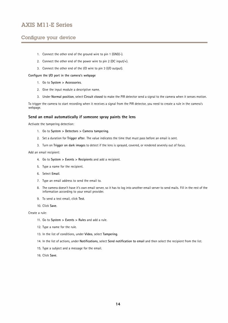
1. Connect the other end of the ground wire to pin 1 (GND/-).
2. Connect the other end of the power wire to pin 2 (DC input/+).
3. Connect the other end of the I/O wire to pin 3 (I/O output).
Configure the I/O port in the camera’s webpage
1. Go to System > Accessories.
2. Give the input module a descriptive name.
3. Under Normal position, select Circuit closed to make the PIR detector send a signal to the camera when it senses motion.
To trigger the camera to start recording when it receives a signal from the PIR detector, you need to create a rule in the camera’swebpage.
Send an email automatically if someone spray paints the lens
Activate the tampering detection:
1. Go to System > Detectors > Camera tampering.
2. Set a duration for Trigger after. The value indicates the time that must pass before an email is sent.
3. Turn on Trigger on dark images to detect if the lens is sprayed, covered, or rendered severely out of focus.
Add an email recipient:
4. Go to System > Events > Recipients and add a recipient.
5. Type a name for the recipient.
6. Select Email.
7. Type an email address to send the email to.
8. The camera doesn’t have it’s own email server, so it has to log into another email server to send mails. Fill in the rest of theinformation according to your email provider.
9. To send a test email, click Test.
10. Click Save.
Create a rule:
11. Go to System > Events > Rules and add a rule.
12. Type a name for the rule.
13. In the list of conditions, under Video, select Tampering.
14. In the list of actions, under Notifications, select Send notification to email and then select the recipient from the list.
15. Type a subject and a message for the email.
16. Click Save.
14

AXIS M11-E Series
The device interface
The device interface
NoteSupport for the features and settings described in this section varies between devices.
Show or hide the main menu.
Access the product help.
Change the language.
Set light theme or dark theme.
See information about the user who is logged in.
The context menu contains:
• Analytics data: Accept to share non-personal browser data.• Feedback: Share any feedback to help us improve your user experience.• Legal: View information about cookies and licenses.• About: View device information, including firmware version and serial number.
StatusNTP sync
Shows NTP synchronization information, including if the device is in sync with an NTP server and the time remaining untilthe next sync.
NTP settings: Click to go to the Date and time page where you can change the NTP settings.
Device info
Shows device information, including firmware version and serial number.
Upgrade firmware: Click to go to the Maintenance page where you can do a firmware upgrade.
Video
Click to play the live video stream.
Click to freeze the live video stream.
Click to take a snapshot of the live video stream. The file is saved in the ‘Downloads’ folder on your computer. The imagefile name is [snapshot_YYYY_MM_DD_HH_MM_SS.jpg]. The size of the snapshot depends on the compression that is appliedfrom the specific web-browser engine where the snapshot is received, therefore, the snapshot size may vary from the actualcompression setting that is configured in the device.
15

AXIS M11-E Series
The device interface
Click to show I/O output ports. Use the switch to open or close the circuit of a port, for example to test externaldevices.
Click to manually turn on or turn off the IR illumination.
Click to access onscreen controls:
• Predefined controls: Turn on to use the available onscreen controls.
• Custom controls: Click Add custom control to add an onscreen control.
Click to manually turn on the heater for a selected period of time.
Click to start a continuous recording of the live video stream. Click again to stop the recording. If a recording is ongoing, itwill resume automatically after a reboot.
Click to show the storage that is configured for the device. To configure the storage you need to be logged in as anadministrator.
Click to access more settings:
• Video format: Select the encoding format to use in the live view. If you select a format with video compression, itresults in a higher CPU and memory usage.
• Client stream information: Turn on to show dynamic information about the video stream used by the browser thatshows the live video stream. The bitrate information differs from the information shown in a text overlay, because ofdifferent information sources. The bitrate in the client stream information is the bitrate of the last second, and itcomes from the encoding driver of the device. The bitrate in the overlay is the average bitrate of the last 5 seconds,and it comes from the browser. Both values cover only the raw video stream and not the additional bandwidthgenerated when it’s transported over the network through UDP/TCP/HTTP.
• Adaptive stream: Turn on to adapt the image resolution to the viewing client’s actual display resolution, to increasethe user experience and help prevent a possible overload of the client’s hardware. The adaptive stream is onlyapplied when you view the live video stream in the web interface in a browser. When adaptive stream is turned on,the maximum frame rate is 30 fps. If you take a snapshot while adaptive stream is turned on, it will use the imageresolution selected by the adaptive stream.
• Level grid: Click to show the level grid. The grid helps you decide if the image is horizontally aligned. Click
to hide it.
• Pixel counter: Click to show the pixel counter. Drag and resize the box to contain your area of interest. You canalso define the pixel size of the box in the Width and Height fields.
• Refresh: Click to refresh the still image in the live view.
Click to show the live view at full resolution. If the full resolution is larger than your screen size, use the smaller image tonavigate in the image.
Click to show the live video stream in full screen. Press ESC to exit full screen mode.
16

AXIS M11-E Series
The device interface
Installation
Capture mode : A capture mode is a preset configuration that defines how the camera captures images. When you changethe capture mode, it can affect many other settings, such as view areas and privacy masks.
Mounting position : The orientation of the image can change depending on how the camera is mounted.
Power line frequency: Select the frequency that is used in your region to minimize image flicker. The American regionsusually use 60 Hz. The rest of the world mostly uses 50 Hz. If you're not sure of your region's power line frequency, checkwith the local authorities.
Rotate: Select the preferred image orientation.
Image
Appearance
Scene profile : Select a scene profile that suits your surveillance scenario. A scene profile optimizes image settings,including color level, brightness, sharpness, contrast, and local contrast, for a specific environment or purpose.
• Forensic: Suitable for surveillance purposes.
• Indoor : Suitable for indoor environments.
• Outdoor : Suitable for outdoor environments.• Vivid: Useful for demonstration purposes.• Traffic overview: Suitable for vehicle traffic monitoring.
Saturation: Use the slider to adjust the color intensity. You can for example get a grayscale image.
Contrast: Use the slider to adjust the difference between light and dark.
Brightness: Use the slider to adjust the light intensity. This can make objects easier to see. Brightness is applied after imagecapture, and doesn’t affect the information in the image. To get more details from a dark area, it’s usually better to increasegain or exposure time.
17

AXIS M11-E Series
The device interface
Sharpness: Use the slider to make objects in the image appear sharper by adjusting the edge contrast. If you increase thesharpness, it may increase the bitrate and the amount of storage space needed as well.
Wide dynamic range
WDR: Turn on to make both bright and dark areas of the image visible.
Local contrast : Use the slider to adjust the contrast of the image. A higher value makes the contrast higher betweendark and light areas.
Tone mapping : Use the slider to adjust the amount of tone mapping that is applied to the image. If the value is set tozero only the standard gamma correction is applied, while a higher value increases the visibility in the image.
White balance
When the camera detects the color temperature of the incoming light, it can adjust the image to make the colors look morenatural. If this is not sufficient, you can select a suitable light source from the list.
The automatic white balance setting reduces the risk of color flicker by adapting to changes gradually. If the lighting changes, orwhen the camera is first started, it can take up to 30 seconds to adapt to the new light source. If there is more than one typeof light source in a scene, that is they differ in color temperature, the dominating light source acts as a reference for theautomatic white balance algorithm. This behavior can be overridden by choosing a fixed white balance setting that matchesthe light source you want to use as a reference.
Light environment:
• Automatic: Automatic identification and compensation for the light source color. This is the recommended settingwhich can be used in most situations.
• Automatic – outdoors : Automatic identification and compensation for the light source color. This is therecommended setting which can be used in most outdoor situations.
• Custom – indoors : Fixed color adjustment for a room with some artificial light other than fluorescent lightingand good for a normal color temperature around 2800 K.
• Custom – outdoors : Fixed color adjustment for sunny weather conditions with a color temperature around5500 K.
• Fixed – fluorescent 1: Fixed color adjustment for fluorescent lighting with a color temperature around 4000 K.
18
AXIS M11-E Series
The device interface
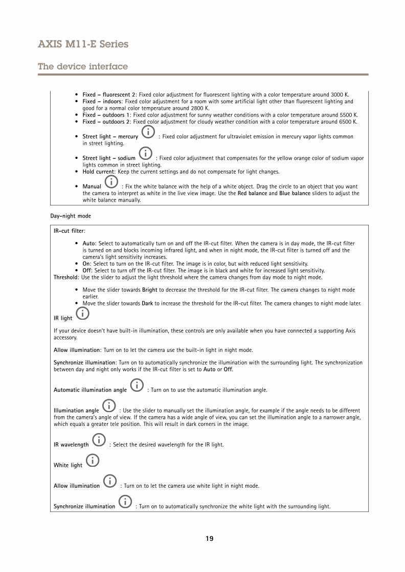
• Fixed – fluorescent 2: Fixed color adjustment for fluorescent lighting with a color temperature around 3000 K.• Fixed – indoors: Fixed color adjustment for a room with some artificial light other than fluorescent lighting and
good for a normal color temperature around 2800 K.• Fixed – outdoors 1: Fixed color adjustment for sunny weather conditions with a color temperature around 5500 K.• Fixed – outdoors 2: Fixed color adjustment for cloudy weather condition with a color temperature around 6500 K.
• Street light – mercury : Fixed color adjustment for ultraviolet emission in mercury vapor lights commonin street lighting.
• Street light – sodium : Fixed color adjustment that compensates for the yellow orange color of sodium vaporlights common in street lighting.
• Hold current: Keep the current settings and do not compensate for light changes.
• Manual : Fix the white balance with the help of a white object. Drag the circle to an object that you wantthe camera to interpret as white in the live view image. Use the Red balance and Blue balance sliders to adjust thewhite balance manually.
Day-night mode
IR-cut filter:
• Auto: Select to automatically turn on and off the IR-cut filter. When the camera is in day mode, the IR-cut filteris turned on and blocks incoming infrared light, and when in night mode, the IR-cut filter is turned off and thecamera’s light sensitivity increases.
• On: Select to turn on the IR-cut filter. The image is in color, but with reduced light sensitivity.• Off: Select to turn off the IR-cut filter. The image is in black and white for increased light sensitivity.
Threshold: Use the slider to adjust the light threshold where the camera changes from day mode to night mode.
• Move the slider towards Bright to decrease the threshold for the IR-cut filter. The camera changes to night modeearlier.
• Move the slider towards Dark to increase the threshold for the IR-cut filter. The camera changes to night mode later.
IR light
If your device doesn’t have built-in illumination, these controls are only available when you have connected a supporting Axisaccessory.
Allow illumination: Turn on to let the camera use the built-in light in night mode.
Synchronize illumination: Turn on to automatically synchronize the illumination with the surrounding light. The synchronizationbetween day and night only works if the IR-cut filter is set to Auto or Off.
Automatic illumination angle : Turn on to use the automatic illumination angle.
Illumination angle : Use the slider to manually set the illumination angle, for example if the angle needs to be differentfrom the camera’s angle of view. If the camera has a wide angle of view, you can set the illumination angle to a narrower angle,which equals a greater tele position. This will result in dark corners in the image.
IR wavelength : Select the desired wavelength for the IR light.
White light
Allow illumination : Turn on to let the camera use white light in night mode.
Synchronize illumination : Turn on to automatically synchronize the white light with the surrounding light.
19

AXIS M11-E Series
The device interface
Exposure
Exposure mode: Select an exposure mode to reduce rapidly changing irregular effects in the image, for example flicker producedby different types of light sources. We recommend you to use the automatic exposure mode, or the same frequency as yourpower network.
• Automatic: The camera adjusts the aperture, gain and shutter automatically.
• Automatic aperture : The camera adjusts the aperture and gain automatically. The shutter is fixed.
• Automatic shutter : The camera adjusts the shutter and gain automatically. The aperture is fixed.• Hold current: Locks the current exposure settings.
• Flicker-free : The camera adjusts the aperture and gain automatically, and uses only the following shutterspeeds: 1/50 s (50 Hz) and 1/60 s (60 Hz).
• Flicker-free 50 Hz : The camera adjusts the aperture and gain automatically, and uses the shutter speed 1/50 s.
• Flicker-free 60 Hz : The camera adjusts the aperture and gain automatically, and uses the shutter speed 1/60 s.
• Flicker-reduced : This is the same as flicker-free, but the camera might use shutter speeds faster than1/100 s (50 Hz) and 1/120 s (60 Hz) for brighter scenes.
• Flicker-reduced 50 Hz : This is the same as flicker-free, but the camera might use shutter speeds fasterthan 1/100 s for brighter scenes.
• Flicker-reduced 60 Hz : This is the same as flicker-free, but the camera might use shutter speeds fasterthan 1/120 s for brighter scenes.
• Manual : The aperture, gain and shutter are fixed.Exposure zone: The exposure zone tells the camera to prioritize image quality in the most important part of the scene. Select thepart of the scene of greatest interest to calculate the automatic exposure levels, for example the area in front of an entrance door.
NoteThe exposure zones are related to the original image (un-rotated), and the names of the zones apply to the original image.This means, for example, that if the video stream is rotated 90°, then the Upper zone becomes the Right zone in thestream, and Left becomes Lower.
• Automatic: Suitable for most situations.• Center: Uses a fixed area in the center of the image to calculate the exposure. The area has a fixed size and
position in the live view.
• Full : Uses the entire live view to calculate the exposure.
• Upper : Uses an area with a fixed size and position in the upper part of the image to calculate the exposure.
• Lower : Uses an area with a fixed size and position in the lower part of the image to calculate the exposure.
• Left : Uses an area with a fixed size and position in the left part of the image to calculate the exposure.
• Right : Uses an area with a fixed size and position in the right part of the image to calculate the exposure.• Spot: Uses an area with a fixed size and position in the live view to calculate the exposure.• Custom: Uses an area in the live view to calculate the exposure. You can adjust the size and position of the area.
Max shutter: Select the shutter speed to provide the best image. Low shutter speeds (longer exposure) might cause motion blurwhen there is movement, and a too high shutter speed might affect the image quality. Max shutter works with max gain toimprove the image.
Max gain: Select the suitable max gain. If you increase the max gain, it improves the visible level of detail in dark images, butalso increases the noise level. More noise can also result in increased use of bandwidth and storage. If you set the max gain
20

AXIS M11-E Series
The device interface
to a high value, images can differ a lot if the light conditions are very different from day to night. Max gain works with maxshutter to improve the image.
Motion-adaptive exposure : Select to reduce motion blur in low-light conditions.
Blur-noise trade-off: Use the slider to adjust the priority between motion blur and noise. If you want to prioritize low bandwidthand have less noise at the expense of details in moving objects, move the slider towards Low noise. If you want to prioritize thepreservation of details in moving objects at the expense of noise and bandwidth, move the slider towards Low motion blur.
NoteYou can change the exposure either by adjusting the exposure or by adjusting the gain. If you increase the exposure time,it results in more motion blur, and if you increase the gain it results in more noise. If you adjust the Blur-noise trade-offtowards Low noise, the exposure will prefer longer exposure times over sensor gain when the exposure is increased, andthe opposite if you adjust the trade-off towards Low motion blur. Both the gain and exposure time will eventually reachtheir maximum values in low-light conditions, regardless of the priority set.
Lock aperture : Turn on to keep the aperture size set by the Aperture slider. Turn off to allow the camera to automaticallyadjust the aperture size. You can, for example, lock the aperture for scenes with permanent light conditions.
Aperture : Use the slider to adjust the aperture size, that is, how much light passes through the lens. To allow more lightto enter the sensor and thereby produce a brighter image in low-light conditions, move the slider towards Open. An open aperturealso reduces the depth of field, which means that objects close to or far from the camera can appear unfocused. To allow more ofthe image to be in focus, move the slider towards Closed.
Exposure level: Use the slider to adjust the image exposure.
Defog : Turn on to detect the effects of foggy weather and automatically remove them for a clearer image.
NoteWe recommend you not to turn on Defog in scenes with low contrast, large light level variations, or when the autofocus isslightly off. This can affect the image quality, for example, by increasing the contrast. Furthermore, too much light cannegatively impact the image quality when defog is active.
Image correction
ImportantWe recommend you not to use multiple image correction features at the same time, since it can lead to performance issues.
Barrel distortion correction (BDC) : Turn on to get a straighter image if it suffers from barrel distortion. Barrel distortionis a lens effect that makes the image appear curved and bent outwards. The condition is seen more clearly when the image iszoomed out.
Crop : Use the slider to adjust the correction level. A lower level means that the image width is kept at the expense ofimage height and resolution. A higher level means that image height and resolution are kept at the expense of image width.
Remove distortion : Use the slider to adjust the correction level. Pucker means that the image width is kept at the expenseof image height and resolution. Bloat means that image height and resolution are kept at the expense of image width.
Electronic image stabilization (EIS) : Turn on to get a smoother and steadier image with less blur. We recommend youto use EIS in environments where the device is mounted in an exposed location and subject to vibrations due to, for example,wind or passing traffic.
21

AXIS M11-E Series
The device interface
Focal length : Use the slider to adjust the focal length. A higher value leads to higher magnification and a narrower angleof view, while a lower value leads to a lower magnification and a wider angle of view.
Stabilizer margin : Use the slider to adjust the size of the stabilizer margin, which determines the level of vibration tostabilize. If the product is mounted in an environment with a lot of vibration, move the slider towards Max. As a result, a smallerscene is captured. If the environment has less vibration, move the slider towards Min.
Straighten image : Turn on and use the slider to straighten the image horizontally by rotating and cropping it digitally. Thefunctionality is useful when it’s not possible to mount the camera exactly level. Ideally, straighten the image during installation.
: Click to show a supporting grid in the image.
: Click to hide the grid.
The image before and after it has been straightened.
Stream
General
Resolution: Select the image resolution suitable for the surveillance scene. A higher resolution increases bandwidth and storage.
Frame rate: To avoid bandwidth problems on the network or reduce storage size, you can limit the frame rate to a fixed amount.If you leave the frame rate at zero, the frame rate is kept at the highest possible rate under the current conditions. A higherframe rate requires more bandwidth and storage capacity.
Compression: Use the slider to adjust the image compression. High compression results in a lower bitrate and lower image quality.Low compression improves the image quality, but uses more bandwidth and storage when you record.
Signed video: Turn on to add the signed video feature to the video. Signed video protects the video from tampering by addingcryptographic signatures to the video.
H.26x encoding
22

AXIS M11-E Series
The device interface
Zipstream: A bitrate reduction technology, optimized for video surveillance, that reduces the average bitrate in an H.264 or H.265stream in real time. Axis Zipstream applies a high bitrate in scenes where there are multiple regions of interest, for example inscenes with moving objects. When the scene is more static, Zipstream applies a lower bitrate, and thereby reduces the requiredstorage. To learn more, see Reducing the bit rate with Axis Zipstream
Select the desired level of bitrate reduction:
• Off: No bitrate reduction.• Low: No visible quality degradation in most scenes. This is the default option and it can be used in all types
of scenes to reduce the bitrate.• Medium: Visible effects in some scenes through less noise and a slightly lower level of detail in regions of lower
interest, for example where there’s no movement.• High: Visible effects in some scenes through less noise and a lower level of detail in regions of lower interest,
for example where there’s no movement. We recommend this level for cloud-connected devices and devices thatuse local storage.
• Higher: Visible effects in some scenes through less noise and a lower level of detail in regions of lower interest,for example where there’s no movement.
• Extreme: Visible effects in most scenes. The bitrate is optimized for smallest possible storage.Dynamic FPS (frames per second): Turn on to allow the bandwidth to vary based on the level of activity in the scene. Moreactivity requires more bandwidth.
Lower limit : Enter a value to adjust the frame rate between minimal fps and the stream default fps based on scenemotion. We recommend you to use lower limit in scenes with very little motion, where the fps could drop to 1 or lower.
Dynamic GOP (Group of Pictures): Turn on to dynamically adjust the interval between I-frames based on the level of activityin the scene.
Upper limit : Enter a maximum GOP length, that is, the maximum number of P-frames between two I-frames.
P-frames: Enter the desired number of P-frames. The higher the number, the less bandwidth is required. However, if there arenetwork congestion, there could be a noticeable deterioration in the video quality.
H.264 profile:
• Baseline : Use if the video management client doesn’t support CABAC entropy coding.• Main: Use if the video management client supports CABAC entropy coding, to achieve higher compression with
maintained video quality. It requires more processing power to decode compared to the baseline profile.• High: Use if the video management client supports CABAC entropy coding, to achieve even higher compression than
with the main profile. It requires more processing power to decode compared to the main profile.Bitrate control:
• Average: Select to automatically adjust the bitrate over a longer time period and provide the best possible imagequality based on the available storage.
- Click to calculate the target bitrate based on available storage, retention time, and bitrate limit.- Target bitrate: Enter desired target bitrate.- Retention time: Enter the number of days to keep the recordings.- Storage: Shows the estimated storage that can be used for the stream.- Maximum bitrate: Turn on to set a bitrate limit.
- Bitrate limit : Enter a bitrate limit that is higher than the target bitrate.• Maximum: Select to set a maximum instant bitrate of the stream based on your network bandwidth.
- Maximum: Enter the maximum bitrate.• Variable: Select to allow the bitrate to vary based on the level of activity in the scene. More activity requires more
bandwidth. We recommend this option for most situations.
Orientation
23

AXIS M11-E Series
The device interface
Rotate : Rotate the image to match your requirements.
Mirror: Turn on to mirror the image.
Audio
Include: Turn on to use audio in the video stream.
Source : Select what audio source to use.
Stereo : Turn on to include built-in audio as well as audio from an external microphone.
Overlays
: Click to add an overlay. Select the type of overlay from the dropdown list:
• Text: Select to show a text that is integrated in the live view image and visible in all views, recordings and snapshots.You can enter your own text, and you can also include pre-configured modifiers to automatically show for exampletime, date, frame rate.
- : Click to add the date modifier %F to show yyyy-mm-dd.
- : Click to add the time modifier %X to show hh:mm:ss (24-hour clock).
- : Click to select any of the modifiers shown in the list to add them to the text box. For example,%a shows the day of the week.
- Size: Select the desired font size.- Appearance: Select the text color and background color, for example, white text on a black background
(default).
- : Select the position of the overlay in the image.• Image: Select to show a static image superimposed over the video stream. You can use .bmp, .png, .jpeg, or .svg files.
To upload an image, click Images. Before you upload an image, you can choose to:- Scale with resolution: Select to automatically scale the overlay image to fit the video resolution.- Use transparency: Select and enter the RGB hexadecimal value for that color. Use the format RRGGBB.
Examples of hexadecimal values: FFFFFF for white, 000000 for black, FF00000 for red, 6633FF for blue, and669900 for green. Only for .bmp images.
• Streaming indicator : Select to show an animation superimposed over the video stream. The animationindicates that the video stream is live, even if the scene doesn’t contain any motion.
- Appearance: Select the animation color and background color, for example, red animation on a transparentbackground (default).
- Size: Select the desired font size.
- : Select the position of the overlay in the image.
24

AXIS M11-E Series
The device interface
View areas
: Click to create a view area.
Click the view area to access settings.
Name: Enter a name for the view area. The maximum length is 64 characters.
Aspect ratio: Select desired aspect ratio. The resolution adjusts automatically.
PTZ: Turn on to use pan, tilt, and zoom functionality in the view area.
Privacy masks
: Click to create a new privacy mask. The maximum number of masks depend on the complexity of all masks combined.Each mask can have maximum 10 anchor points.
Privacy masks: Click to change the color of all privacy masks, or to delete all privacy masks permanently.
Mask x: Click to rename, disable, or permanently delete the mask.
Audio
Device settings
Input: Turn on or off audio input. Shows the type of input.
Allow stream extraction: Turn on to allow stream extraction.
Input type: Select the type of input, for instance if it’s a microphone or line-in.
Power type: Select power type for your input.
Activate changes: Click to activate your selection.
Separate gain controls: Turn on to adjust the gain separately for the different input types.
Automatic gain control : Turn on to dynamically adapt the gain to changes in the sound.
Gain: Use the slider to change the gain. Click the microphone icon to mute or unmute.
Output : Shows the type of output.
Gain: Use the slider to change the gain. Click the speaker icon to mute or unmute.
Stream
Encoding: Select the encoding to use for the input source streaming. You can only choose encoding if audio input is turned on. Ifaudio input is tuned off, click Enable audio input to turn it on.
25

AXIS M11-E Series
The device interface
Recordings
Click to filter the recordings.
From: Show recordings done after a certain point in time.
To: Show recordings up until a certain point in time.
Source : Show recordings based on source.
Event: Show recordings based on events.
Storage: Show recordings based on storage type.
Click to play the recording.
Click to stop the recording.
Click to show more information and options about the recording.
Set export range: If you only want to export part of the recording, enter from when to when.
Click to delete the recording.
Export: Click to export (part of) the recording.
AppsAdd app: Click to install a new app.
Find more apps: Click to go to an overview page of Axis apps.
The context menu contains:
• App log: Click to view a log of the app events. The log is helpful when you contact support.• Activate license with a key: If the app requires a license, you need to activate it. Use this option if your device
doesn’t have internet access.If you don’t have a license key, go to axis.com/applications. You need a license code and the Axis product serialnumber to generate a license key.
• Activate license automatically: If the app requires a license, you need to activate it. Use this option if your device hasinternet access. You need a license code to activate the license.
• Deactivate the license: Deactivate the license to use it in another device. If you deactivate the license, you alsoremove it from the device. To deactivate the license requires internet access.
• Delete: Delete the app permanently from the device. If you don’t deactivate the license first, it remains active.Note
The device’s performance might be affected if you run several apps at the same time.
Start: Start or stop the app.
Open: Click to access the app’s settings. The available settings depend on the application. Some applications don’t have anysettings.
26

AXIS M11-E Series
The device interface
System
Date and time
The time format depends on the web browser’s language settings.
NoteWe recommend you to synchronize the device’s date and time with an NTP server.
Synchronization: Select an option for synchronizing the device’s date and time.
• Automatic date and time (NTP server using DHCP): Synchronize with the NTP server connected to the DHCP server.• Automatic date and time (manual NTP server): Synchronize with NTP servers of your choice.
- Primary NTP server and Secondary NTP server: Enter the IP address of one or two NTP servers. When you usetwo NTP servers, the device synchronizes and adapts its time based on input from both.
• Custom date and time: Manually set the date and time. Click Get from system to fetch the date and time settingsonce from your computer or mobile device.
Time zone: Select which time zone to use. Time will be automatically adjusted for daylight saving time and standard time.
NoteThe system uses the date and time settings in all recordings, logs and system settings.
Network
IPv4 and IPv6
IPv4
• Automatic IP (DHCP) and DNS (DHCP): The recommended setting for most networks. The current settings areupdated automatically.
• Automatic IP (DHCP) and manual DNS: Contact your network administrator to configure the manual settings. Thecurrent automatic settings are updated automatically.
• Manual IP and DNS: Contact your network administrator to configure the settings.IP address: Enter a unique IP address for the device. Static IP addresses can be assigned at random within isolated networks,provided that each address is unique. To avoid conflicts, we recommend you to contact your network administrator before youassign a static IP address.
Subnet mask: Enter the subnet mask.
Router: Enter the IP address of the default router (gateway) used to connect devices that are attached to different networks andnetwork segments.
Hostname: Enter the hostname.
Search domains: When you use a hostname that is not fully qualified, click Add search domain and enter a domain in which tosearch for the hostname used by the device.
DNS servers: Click Add DNS server and enter the IP address of the primary DNS server. This provides the translation of hostnamesto IP addresses on your network.
IPv6
Assign IPv6 automatically: Select to let the network router assign an IP address to the device automatically.
HTTP and HTTPS
27

AXIS M11-E Series
The device interface
Allow access through: Select if a user is allowed to connect to the device through the HTTP, HTTPS, or both HTTP and HTTPSprotocols.
HTTPS is a protocol that provides encryption for page requests from users and for the pages returned by the web server. Theencrypted exchange of information is governed by the use of an HTTPS certificate, which guarantees the authenticity of the server.
To use HTTPS on the device, you must install an HTTPS certificate. Go to System > Security to create and install certificates.
NoteIf you view encrypted web pages through HTTPS, you might experience a drop in performance, especially when yourequest a page for the first time.
HTTP port: Enter the HTTP port to use. Port 80 or any port in the range 1024-65535 are allowed. If you are logged in as anadministrator, you can also enter any port in the range 1-1023. If you use a port in this range, you get a warning.
HTTPS port: Enter the HTTPS port to use. Port 443 or any port in the range 1024-65535 are allowed. If you are logged in as anadministrator, you can also enter any port in the range 1-1023. If you use a port in this range, you get a warning.
Certificate: Select a certificate to enable HTTPS for the device.
Friendly name
Bonjour®: Turn on to allow automatic discovery on the network.
Bonjour name: Enter a friendly name to be visible on the network. The default name is the device name and MAC address.
Use UPnP®: Turn on to allow automatic discovery on the network.
UPnP name: Enter a friendly name to be visible on the network. The default name is the device name and MAC address.
One-click cloud connection
One-click cloud connection (O3C) together with an O3C service provides easy and secure internet access to live and recorded videofrom any location. For more information, see axis.com/end-to-end-solutions/hosted-services.
Allow O3C:
• One-click: The default setting. Press and hold the control button on the device to connect to an O3C service over theinternet. You need to register the device with the O3C service within 24 hours after you press the control button.Otherwise, the device disconnects from the O3C service. Once you have registered the device, Always is enabled andthe device stays connected to the O3C service.
• Always: The device constantly attempts to connect to an O3C service over the internet. Once you have registered thedevice, it stays connected to the O3C service. Use this option if the control button on the device is out of reach.
• No: Disables the O3C service.Proxy settings: If needed, enter the proxy settings to connect to the HTTP server.
Host: Enter the proxy server’s address.
Port: Enter the port number used for access.
Login and Password: If needed, enter username and password for the proxy server.
Authentication method:
• Basic: This method is the most compatible authentication scheme for HTTP. It’s less secure than the Digest methodbecause it sends the username and password unencrypted to the server.
• Digest: This method is more secure because it always transfers the password encrypted across the network.• Auto: This option lets the device select the authentication method depending on the supported methods. It prioritizes
the Digest method over the Basic method.Owner authentication key (OAK): Click Get key to fetch the owner authentication key. This is only possible if the device isconnected to the internet without a firewall or proxy.
28

AXIS M11-E Series
The device interface
SNMP
The Simple Network Management Protocol (SNMP) allows remote management of network devices.
SNMP: Select the version of SNMP to use.
• v1 and v2c:- Read community: Enter the community name that has read-only access to all supported SNMP objects. The
default value is public.- Write community: Enter the community name that has read/write access to all supported SNMP objects
(except read-only objects). The default value is write.- Activate traps: Turn on to activate trap reporting. The device uses traps to send messages for important
events or status changes to a management system. In the device interface, you can set up traps for SNMP v1and v2c. Traps are automatically turned off if you change to SNMP v3 or turn off SNMP. If you use SNMP v3,you can set up traps through the SNMP v3 management application.
- Trap address: Enter the IP address or host name of the management server.- Trap community: Enter the community to use when the device sends a trap message to the management
system.- Traps:- Cold start: Sends a trap message when the device starts.- Warm start: Sends a trap message when you change an SNMP setting.- Link up: Sends a trap message when a link changes from down to up.- Authentication failed: Sends a trap message when an authentication attempt fails.
NoteAll Axis Video MIB traps are enabled when you turn on SNMP v1 and v2c traps. For more information, seeAXIS OS Portal > SNMP.
• v3: SNMP v3 is a more secure version, which provides encryption and secure passwords. To use SNMP v3, werecommend you to activate HTTPS, as the password is then sent through HTTPS. This also prevents unauthorizedparties to access unencrypted SNMP v1 and v2c traps. If you use SNMP v3, you can set up traps through the SNMP v3management application.
- Password for the account “initial”: Enter the SNMP password for the account named “initial”. Although thepassword can be sent without activating HTTPS, we don’t recommend it. The SNMP v3 password can onlybe set once, and preferably only when HTTPS is enabled. Once the password is set, the password field is nolonger displayed. To set the password again, you must reset the device to factory default settings.
Connected clients
The list shows all clients that are connected to the device.
Update: Click to refresh the list.
Security
Certificates
Certificates are used to authenticate devices on a network. The device supports two types of certificates:
• Client/server certificatesA client/server certificate validates the device’s identity, and can be self-signed or issued by a Certificate Authority (CA).A self-signed certificate offers limited protection and can be used before a CA-issued certificate has been obtained.
• CA certificatesYou can use a CA certificate to authenticate a peer certificate, for example to validate the identity of an authenticationserver when the device connects to a network protected by IEEE 802.1X. The device has several pre-installed CAcertificates.
These formats are supported:
• Certificate formats: .PEM, .CER, and .PFX• Private key formats: PKCS#1 and PKCS#12
29

AXIS M11-E Series
The device interface
ImportantIf you reset the device to factory default, all certificates are deleted. Any pre-installed CA certificates are reinstalled.
Filter the certificates in the list.
Add certificate : Click to add a certificate.
The context menu contains:
• Certificate information: View an installed certificate’s properties.• Delete certificate: Delete the certificate.• Create certificate signing request: Create a certificate signing request to send to a registration authority to apply
for a digital identity certificate.
IEEE 802.1x
IEEE 802.1x is an IEEE standard for port-based network admission control providing secure authentication of wired and wirelessnetwork devices. IEEE 802.1x is based on EAP (Extensible Authentication Protocol).
To access a network protected by IEEE 802.1x, network devices must authenticate themselves. The authentication is performed byan authentication server, typically a RADIUS server (for example FreeRADIUS and Microsoft Internet Authentication Server).
Certificates
When configured without a CA certificate, server certificate validation is disabled and the device tries to authenticate itselfregardless of what network it is connected to.
When using a certificate, in Axis' implementation, the device and the authentication server authenticate themselves with digitalcertificates using EAP-TLS (Extensible Authentication Protocol - Transport Layer Security).
To allow the device to access a network protected through certificates, a signed client certificate must be installed on the device.
Client certificate: Select a client certificate to use IEEE 802.1x. The authentication server uses the certificate to validate theclient’s identity.
CA certificate: Select a CA certificate to validate the authentication server’s identity. When no certificate is selected, the devicetries to authenticate itself regardless of what network it is connected to.
EAP identity: Enter the user identity associated with the client certificate.
EAPOL version: Select the EAPOL version that is used in the network switch.
Use IEEE 802.1x: Select to use the IEEE 802.1x protocol.
Prevent brute-force attacks
Blocking: Turn on to block brute-force attacks. A brute-force attack uses trial-and-error to guess login info or encryption keys.
Blocking period: Enter the number of seconds to block a brute-force attack.
Blocking conditions: Enter the number of authentication failures allowed per second before the block starts. You can set thenumber of failures allowed both on page level and device level.
IP address filter
30

AXIS M11-E Series
The device interface
Use filter: Select to filter which IP addresses that are allowed to access the device.
Policy: Choose whether to Allow access or Deny access for certain IP addresses.
Addresses: Enter the IP numbers that are either allowed or denied access to the device. You can also use the CIDR format.
Custom-signed firmware certificate
To install test firmware or other custom firmware from Axis on the device, you need a custom-signed firmware certificate. Thecertificate verifies that the firmware is approved by both the device owner and Axis. The firmware can only run on a specificdevice which is identified by its unique serial number and chip ID. Custom-signed firmware certificates can only be createdby Axis, since Axis holds the key to sign them.
Click Install to install the certificate. You need to install the certificate before you install the firmware.
Users
Add user: Click to add a new user. You can add up to 100 users.
Username: Enter a unique username.
New password: Enter a password for the user. Passwords must be 1 to 64 characters long. Only ASCII printable characters (code32 to 126) are allowed in the password, for example letters, numbers, punctuation, and some symbols.
Repeat password: Enter the same password again.
Role:
• Administrator: Has full access to all settings. Administrators can also add, update, and remove other users.• Operator: Has access to all settings except:
- All System settings.- Adding apps.
• Viewer: Has access to:- Watch and take snapshots of a video stream.- Watch and export recordings.- With PTZ user access: pan, tilt, and zoom.
The context menu contains:
Update user: Edit the user’s properties.
Delete user: Delete the user. You can’t delete the root user.
Anonymous users
Allow anonymous viewers: Turn on to allow anyone to access the device as a viewer without having to log in with a user account.
Allow anonymous PTZ operators: Turn on to allow anonymous users to pan, tilt, and zoom the image.
Events
Rules
31

AXIS M11-E Series
The device interface
A rule defines the conditions that must be met for the product to perform an action. The list shows all the currently configuredrules in the product.
NoteYou can create up to 256 action rules.
Add a rule: Click to create a rule.
Name: Enter a name for the rule.
Wait between actions: Enter the minimum time (hh:mm:ss) that must pass between rule activations. It is useful if the rule isactivated by for example day-night mode conditions, to avoid that small light changes during sunrise and sunset activatethe rule repeatedly.
Condition: Select a condition from the list. A condition must be met for the device to perform an action. If multipleconditions are defined, all of them must be met to trigger the action. For information about specific conditions, seeGet started with rules for events.
Use this condition as a trigger: Select to make this first condition function only as a starting trigger. It means that once the ruleis activated it remains active for as long as all the other conditions are met, no matter the state of the first condition. If you don’tselect this option, the rule will simply be active whenever all the conditions are met.
Invert this condition: Select if you want the condition to be the opposite of your selection.
Add a condition: Click to add an additional condition.
Action: Select an action from the list and enter its required information. For information about specific actions, seeGet started with rules for events.
Recipients
You can set up your device to notify recipients about events or send files. The list shows all the recipients currently configured inthe product, along with information about their configuration.
NoteYou can create up to 20 recipients.
Add a recipient: Click to add a recipient.
Name: Enter a name for the recipient.
Type: Select from the list:
• FTP- Host: Enter the server's IP address or hostname. If you enter a hostname, make sure that a DNS server is
specified under System > Network > IPv4 and IPv6.- Port: Enter the port number used by the FTP server. The default is 21.- Folder: Enter the path to the directory where you want to store files. If this directory doesn’t already exist
on the FTP server, you will get an error message when uploading files.- Username: Enter the username for the login.- Password: Enter the password for the login.- Use temporary file name: Select to upload files with temporary, automatically generated filenames. The
files get renamed to the desired names when the upload completes. If the upload is aborted/interrupted,you don’t get any corrupt files. However, you probably still get the temporary files. This way you know thatall files that have the desired name, are correct.
32

AXIS M11-E Series
The device interface
- Use passive FTP: Under normal circumstances the product simply requests the target FTP server to open thedata connection. The device actively initiates both the FTP control and data connections to the target server.This is normally needed if there is a firewall between the device and the target FTP server.
• HTTP- URL: Enter the network address to the HTTP server and the script that will handle the request. For example:
http://192.168.254.10/cgi-bin/notify.cgi.- Username: Enter the username for the login.- Password: Enter the password for the login.- Proxy: Turn on and enter the required information if a proxy server must be passed to connect to the HTTP
server.• HTTPS
- URL: Enter the network address to the HTTPS server and the script that will handle the request. For example:https://192.168.254.10/cgi-bin/notify.cgi.
- Validate server certificate: Select to validate the certificate that was created by HTTPS server.- Username: Enter the username for the login.- Password: Enter the password for the login.- Proxy: Turn on and enter the required information if a proxy server must be passed to connect to the HTTPS
server.• Network storage
You can add network storage such as a NAS (Network Attached Storage) and use it as a recipient to store files.The files are stored in the Matroska (MKV) file format.
- Host: Enter the IP address or hostname for the network storage.- Share: Enter the name of the share on the host.- Folder: Enter the path to the directory where you want to store files.- Username: Enter the username for the login.- Password: Enter the password for the login.
• SFTP- Host: Enter the server's IP address or hostname. If you enter a hostname, make sure that a DNS server is
specified under System > Network > IPv4 and IPv6.- Port: Enter the port number used by the SFTP server. The default is 22.- Folder: Enter the path to the directory where you want to store files. If this directory doesn’t already exist on
the SFTP server, you will get an error message when uploading files.- Username: Enter the username for the login.- Password: Enter the password for the login.- SSH host public key (MD5): Enter the fingerprint of the remote host’s public key (a 32 hexadecimal digits
string). The SFTP client supports SFTP servers using SSH-2 with RSA, DSA, ECDSA, and ED25519 host keytypes. RSA is the preferred method during negotiation, followed by ECDSA, ED25519, and DSA. Make sure toenter the right MD5 host key that is used by your SFTP server.
- Use temporary file name: Select to upload files with temporary, automatically generated filenames. Thefiles get renamed to the desired names when the upload completes. If the upload is aborted/interrupted,you don’t get any corrupt files. However, you probably still get the temporary files. This way you know thatall files that have the desired name, are correct.
• Email- Send email to: Enter the email address to send emails to. To enter multiple addresses, use commas to
separate them.- Send email from: Enter the email address of the sending server.- Username: Enter the username for the mail server. Leave this field empty if the mail server does not
require authentication.- Password: Enter the password for the mail server. Leave this field empty if the mail server does not require
authentication.- Email server (SMTP): Enter the name of the SMTP server, for example smtp.gmail.com, smtp.mail.yahoo.com.- Port: Enter the port number for the SMTP server, using values in the range 0-65535. The default value is 587.- Encryption: To use encryption, select either SSL or TLS.- Validate server certificate: If you use encryption, select to validate the identity of the device. The certificate
can be self-signed or issued by a Certificate Authority (CA).- POP authentication: Turn on to enter the name of the POP server, for example pop.gmail.com.
NoteSome email providers have security filters that prevent users from receiving or viewing large amount ofattachments, from receiving scheduled emails and similar. Check the email provider's security policy to avoidyour email account being locked or missing out on your expected emails.
33

AXIS M11-E Series
The device interface
• TCP- Host: Enter the server's IP address or hostname. If you enter a hostname, make sure that a DNS server is
specified under System > Network > IPv4 and IPv6.- Port: Enter the port number used to access the server.
Test: Click to test the setup.
The context menu contains:
View recipient: Click to view all the recipient details.
Copy recipient: Click to copy a recipient. When you copy, you can make changes to the new recipient.
Delete recipient: Click to delete the recipient permanently.
Schedules
Schedules and pulses can be used as conditions in rules. The list shows all the schedules and pulses currently configured in theproduct, along with information about their configuration.
Add schedule: Click to create a schedule or pulse.
Manual trigger
The manual trigger is used to manually trigger a rule. The manual trigger can for example be used to validate actions duringproduct installation and configuration.
MQTT
MQTT (Message Queuing Telemetry Transport) is a standard messaging protocol for the Internet of Things (IoT). It was designed forsimplified IoT integration and is used in a wide variety of industries to connect remote devices with a small code footprint andminimal network bandwidth. The MQTT client in Axis device firmware can simplify integration of data and events produced in thedevice to systems which are not video management systems (VMS).
Set up the device as an MQTT client. MQTT communication is based on two entities, the clients and the broker. The clients cansend and receive messages. The broker is responsible for routing messages between clients.
You can learn more about MQTT in AXIS OS Portal.
MQTT client
Connect: Turn on or off the MQTT client.
Status: Shows the current status of the MQTT client.
Broker
Host: Enter the hostname or IP address of the MQTT server.
Protocol: Select which protocol to use.
Port: Enter the port number.
• 1883 is the default value for MQTT over TCP• 8883 is the default value for MQTT over SSL• 80 is the default value for MQTT over WebSocket• 443 is the default value for MQTT over WebSocket Secure
Username: Enter the username that the client will use to access the server.
34

AXIS M11-E Series
The device interface
Password: Enter a password for the username.
Client ID: Enter a client ID. The client identifier is sent to the server when the client connects to it.
Clean session: Controls the behavior at connection and disconnection time. When selected, the state information is discardedat connect and disconnect.
Keep alive interval: The keep alive interval enables the client to detect when the server is no longer available without havingto wait for the long TCP/IP timeout.
Timeout: The time interval in seconds to allow a connect to complete. Default value: 60
Device topic prefix: Used in the default values for the topic in the connect message and LWT message on the MQTT client tab,and in the publication conditions on the MQTT publication tab.
Reconnect automatically: Specifies whether the client should reconnect automatically after a disconnect.
Connect message
Specifies if a message should be sent out when a connection is established.
Send message: Turn on to send messages.
Use default: Turn off to enter your own default message.
Topic: Enter the topic for the default message.
Payload: Enter the content for the default message.
Retain: Select to keep the state of client on this Topic
QoS: Change the QoS layer for the packet flow.
Last Will and Testament message
The Last Will Testament (LWT) lets a client provide a testament along with its credentials when connecting to the broker. If theclient disconnects ungracefully at some point later (maybe because his power source died), it can let the broker deliver a messageto other clients. This LWT message has the same form as an ordinary message and gets routed via the same mechanics.
Send message: Turn on to send messages.
Use default: Turn off to enter your own default message.
Topic: Enter the topic for the default message.
Payload: Enter the content for the default message.
Retain: Select to keep the state of client on this Topic
QoS: Change the QoS layer for the packet flow.
MQTT publication
35

AXIS M11-E Series
The device interface
Use default condition prefix: Select to use the default condition prefix, that is defined using the device topic prefix in theMQTT client tab.
Include condition name: Select to include the topics that describe the condition in the MQTT topic.
Include condition namespaces: Select to include ONVIF topic namespaces in the MQTT topic.
Include serial number: Select to include the device’s serial number in the MQTT payload.
Add condition: Click to add a condition.
Retain: Defines which MQTT messages are sent as retained.
• None: Send all messages as non-retained.• Property: Send only stateful messages as retained.• All: Send both stateful and stateless messages as retained.
QoS: Select the desired level for the MQTT publication.
MQTT subscriptions
Add subscription: Click to add a new MQTT subscription.
Subscription filter: Enter the MQTT topic that you want to subscribe to.
Use device topic prefix: Add the subscription filter as prefix to the MQTT topic.
Subscription type:
• Stateless: Select to convert MQTT messages into a stateless message.• Stateful: Select to convert MQTT messages into a condition. The payload is used as the state.
QoS: Select the desired level for the MQTT subscription.
Storage
Network storage
Add network storage: Click to add a network share where you can save recordings.
• Address: Enter the IP address or host name of the host server, typically a NAS (Network Attached Storage). Werecommend you to configure the host to use a fixed IP address (not DHCP since a dynamic IP address can change) orthat you use DNS. Windows SMB/CIFS names are not supported.
• Network share: Enter the name of the shared location on the host server. Several Axis devices can use the samenetwork share, since each device gets its own folder.
• User: If the server requires a login, enter the username. To log in to a specific domain server, typeDOMAIN\username.
• Password: If the server requires a login, enter the password.• SMB version: Select the SMB storage protocol version to connect to the NAS. If you select Auto, the device tries
to negotiate one of the secure versions SMB: 3.02, 3.0, or 2.1. Select 1.0 or 2.0 to connect to older NAS that don’tsupport higher versions. You can read more about SMB support in Axis devices here.
• Add share even if connection test fails: Select to add the network share even if an error is discovered during theconnection test. The error can be, for example, that you didn’t enter a password even though the server requires one.
Remove network storage: Click to remove the connection to the network share. This removes all settings for the network share.
Write protect: Turn on to stop writing to the network share and protect recordings from being removed. You can’t format awrite-protected network share.
Ignore: Turn on to stop storing recordings on the network share.
36

AXIS M11-E Series
The device interface
Retention time: Select how long to keep recordings, to limit the amount of old recordings or to comply with regulations regardingdata storage. If the network storage becomes full, old recordings are removed before the selected time period has passed.
Tools
• Test connection: Test the connection to the network share.• Format: Format the network share, for example when you need to quickly erase all data. cifs is the available file
system option.Click Use tool to activate the selected tool.
Onboard storage
ImportantRisk of data loss and corrupted recordings. Do not remove the SD card while the device is running. Unmount the SDcard before you remove it.
Unmount: Click to safely remove the SD card.
Write protect: Turn on to stop writing to the SD card and protect recordings from being removed. You can’t format awrite-protected SD card.
Autoformat: Turn on to automatically format a newly inserted SD card. It formats the file system into ext4.
Ignore: Turn on to stop storing recordings on the SD card. When you ignore the SD card, the device no longer recognizes that thecard exists. The setting is only available for administrators.
Retention time: Select how long to keep recordings, to limit the amount of old recordings or to comply with regulations regardingdata storage. If the SD card becomes full, old recordings are removed before the selected time period has passed.
Tools
• Check: Check for errors on the SD card. This only works for the ext4 file system.• Repair: Repair errors in the ext4 file system. To repair an SD card with the VFAT file system, eject the SD card, insert it
in a computer and perform a disk repair.• Format: Format the SD card, for example when you need to change the file system or quickly erase all data. VFAT
and ext4 are the two available file system options. The recommended format is ext4, due to its resilience againstdata loss if the card is ejected or if there is an abrupt power loss. However, you need a third-party ext4 driver orapplication to access the file system from Windows®.
• Encrypt: Encrypt data that is stored.• Decrypt: Decrypt data that is stored.• Change password: Change the password required to encrypt the SD card.
Click Use tool to activate the selected tool.
Stream profiles
Click to create and save groups of video stream settings. You can use the settings in different situations, for example incontinuous recording or when you use action rules to record.
ONVIF
ONVIF users
37

AXIS M11-E Series
The device interface
ONVIF (Open Network Video Interface Forum) is a global interface standard that makes it easier for end-users, integrators,consultants, and manufacturers to take advantage of the possibilities offered by network video technology. ONVIF enablesinteroperability between different vendor products, increased flexibility, reduced cost and future-proof systems.
Add user: Click to add a new ONVIF user.
Username: Enter a unique username.
New password: Enter a password for the user. Passwords must be 1 to 64 characters long. Only ASCII printable characters (code32 to 126) are allowed in the password, for example letters, numbers, punctuation, and some symbols.
Repeat password: Enter the same password again
Role:
• Administrator: Has full access to all settings. Administrators can also add, update, and remove other users.• Operator: Has access to all settings except:
- All System settings.- Adding apps.
• Media user: Allows access to the video stream only.
The context menu contains:
Update user: Edit the user’s properties.
Delete user: Delete the user. You can’t delete the root user.
By creating an ONVIF user, you automatically enable ONVIF communication. Use the username and password for all ONVIFcommunication with the device. For more information see the Axis Developer Community at axis.com.
ONVIF media profiles
An ONVIF media profile consists of a set of configurations that you can use to change media stream settings.
Add media profile: Click to add a new ONVIF media profile.
profile_x: Click a profile to edit.
Detectors
Camera tampering
The camera tampering detector generates an alarm when the scene changes, for example because the lens is covered, sprayedor severely put out of focus, and the time in Trigger after has passed. The tampering detector only activates when the camerahas not moved for at least 10 seconds. During this period the detector sets up a scene model to use as a comparison to detecttampering in current images. For the scene model to be set up properly, make sure that the camera is in focus, the lightingconditions are correct, and the camera doesn’t point at a scene that lacks contours, for example a blank wall. Camera tamperingcan be used as a condition to trigger actions.
Trigger after: Enter the minimum time that the tampering conditions must be active before the alarm triggers. This can helpprevent false alarms for known conditions that affect the image.
Trigger on dark images: It is very difficult to generate alarms when the camera lens is sprayed, since it is impossible to distinguishthat event from other situations where the image turns dark in a similar way, for example when the lighting conditions change.Turn on this parameter to generate alarms for all cases where the image turns dark. When it’s turned off, the device doesn’tgenerate any alarm when the image turns dark.
38

AXIS M11-E Series
The device interface
Audio detection
These settings are available for each audio input.
Sound level: Adjust the sound level to a value from 0–100, where 0 is the most sensitive and 100 the least sensitive. Use theactivity indicator as a guide when you set the sound level. When you create events, you can use the sound level as a condition.You can choose to trigger an action if the sound level rises above, falls below or passes the set value.
Accessories
I/O ports
Use digital input to connect external devices that can toggle between an open and closed circuit, for example PIR sensors, door orwindow contacts, and glass break detectors.
Use digital output to connect external devices such as relays and LEDs. You can activate connected devices through the VAPIX®Application Programming Interface or in the device interface.
Port
Name: Edit the text to rename the port.
Direction: indicates that the port is an input port. indicates that it’s an output port. If the port is configurable,you can click the icons to change between input and output.
Normal state: Click open circuit, and for closed circuit.
Current state: Shows the current state of the port. The input or output is activated when the current state is different from thenormal state. An input on the device has an open circuit when it’s disconnected or when there is a voltage above 1 V DC.
NoteDuring restart the output circuit is open. When the restart is complete, the circuit goes back to the normal position. If youchange any settings on this page, the output circuits go back to their normal positions regardless of any active triggers.
Supervised : Turn on to make it possible to detect and trigger actions if someone tampers with the connection to digitalI/O devices. In addition to detecting if an input is open or closed, you can also detect if someone has tampered with it (that is, cutor shorted). To supervise the connection requires additional hardware (end-of-line resistors) in the external I/O loop.
Logs
Reports and logs
Reports
• View the device server report: Click to show information about the product status in a pop-up window. The AccessLog is automatically included in the Server Report.
• Download the device server report: Click to download the server report. It creates a .zip file that contains a completeserver report text file in UTF–8 format, as well as a snapshot of the current live view image. Always include the serverreport .zip file when you contact support.
• Download the crash report: Click to download an archive with detailed information about the server's status. Thecrash report contains information that is in the server report as well as detailed debug information. This report mightcontain sensitive information such as network traces. It can take several minutes to generate the report.
Logs
• View the system log: Click to show information about system events such as device startup, warnings and criticalmessages.
39

AXIS M11-E Series
The device interface
• View the access log: Click to show all failed attempts to access the device, for example when a wrong loginpassword is used.
Network trace
ImportantA network trace file might contain sensitive information, for example certificates or passwords.
A network trace file can help you troubleshoot problems by recording activity on the network. Select the duration of the trace inseconds or minutes, and click Download.
Remote system log
Syslog is a standard for message logging. It allows separation of the software that generates messages, the system that storesthem, and the software that reports and analyzes them. Each message is labeled with a facility code, which indicates the softwaretype generating the message, and assigned a severity level.
Server: Click to add a new server.
Host: Enter the hostname or IP address of the server.
Format: Select which syslog message format to use.
• RFC 3164• RFC 5424
Protocol: Select the protocol and port to use:
• UDP (Default port is 514)• TCP (Default port is 601)• TLS (Default port is 6514)
Severity: Select which messages to send when triggered.
CA certificate set: See the current settings or add a certificate.
Plain config
Plain config is for advanced users with experience of Axis device configuration. Most parameters can be set and edited fromthis page.
MaintenanceRestart: Restart the device. This does not affect any of the current settings. Running applications restart automatically.
Restore: Return most settings to the factory default values. Afterwards you must reconfigure the device and apps, reinstall anyapps that didn’t come preinstalled, and recreate any events and PTZ presets.
40

AXIS M11-E Series
The device interface
ImportantThe only settings saved after restore are:
• Boot protocol (DHCP or static)
• Static IP address
• Default router
• Subnet mask
• 802.1X settings
• O3C settings
Factory default: Return all settings to the factory default values. Afterwards you must reset the IP address to make the deviceaccessible.
NoteAll Axis device firmware is digitally signed to ensure that you only install verified firmware on your device. This furtherincreases the overall minimum cybersecurity level of Axis devices. For more information, see the white paper “Signedfirmware, secure boot, and security of private keys” at axis.com.
Firmware upgrade: Upgrade to a new firmware version. New firmware releases can contain improved functionality, bugfixes, and completely new features. We recommend you to always use the latest release. To download the latest release, goto axis.com/support.
When you upgrade, you can choose between three options:
• Standard upgrade: Upgrade to the new firmware version.• Factory default: Upgrade and return all settings to the factory default values. When you choose this option, you can’t
revert to the previous firmware version after the upgrade.• Autorollback: Upgrade and confirm the upgrade within the set time. If you don’t confirm, the device reverts to the
previous firmware version.Firmware rollback: Revert to the previously installed firmware version.
41

AXIS M11-E Series
Learn more
Learn more
Bitrate controlBitrate control helps you to manage the bandwidth consumption of your video stream.
Variable bitrate (VBR)Variable bitrate allows the bandwidth consumption to vary depending on the level of activity in the scene. The more activity,the more bandwidth you need. With variable bitrate you are guaranteed constant image quality, but you need to make sureyou have storage margins.
Maximum bitrate (MBR)Maximum bitrate lets you set a target bitrate to handle bitrate limitations in your system. You might see a decline in image quality orframe rate as the instantaneous bitrate is kept below the specified target bitrate. You can choose to prioritize either image qualityor frame rate. We recommend that you configure the target bitrate to a higher value than the expected bitrate. This gives you amargin in case there is a high level of activity in the scene.
1 Target bitrate
Average bitrate (ABR)With average bitrate, the bitrate is automatically adjusted over a longer period of time. This is so you can meet the specified targetand provide the best video quality based on your available storage. Bitrate is higher in scenes with a lot of activity, compared to staticscenes. You are more likely to get better image quality when in scenes with a lot of activity if you use the average bitrate option. Youcan define the total storage required to store the video stream for a specified amount of time (retention time) when image quality isadjusted to meet the specified target bitrate. Specify the average bitrate settings in one of the following ways:
• To calculate the estimated storage need, set the target bitrate and the retention time.
42

AXIS M11-E Series
Learn more
• To calculate the average bitrate, based on available storage and required retention time, use the target bitrate calculator.
kbit/s
s
1
2
1 Target bitrate2 Actual average bitrate
You can also turn on maximum bitrate and specify a target bitrate within the average bitrate option.
kbit/s
s
1
2
1 Target bitrate2 Actual average bitrate
View areaA view area is a cropped part of the full view. You can stream and store view areas instead of the full view to minimize bandwidthand storage needs. If you enable PTZ for a view area, you can pan, tilt and zoom within it. By using view areas you can remove partsof the full view, for example, the sky.
When you set up a view area, we recommend you to set the video stream resolution to the same size as or smaller than the view areasize. If you set the video stream resolution larger than the view area size it implies digitally scaled up video after sensor capture,which requires more bandwidth without adding image information.
Privacy masksA privacy mask is a user-defined area that prevents users from viewing a part of the monitored area. In the video stream, privacymasks appear as blocks of solid color or blurred image elements.
You’ll see the privacy mask on all snapshots, recorded video, and live streams.
You can use the VAPIX® application programming interface (API) to turn off the privacy masks.
43

AXIS M11-E Series
Learn more
ImportantIf you use multiple privacy masks it may affect the product’s performance.
OverlaysOverlays are superimposed over the video stream. They are used to provide extra information during recordings, such as a timestamp,or during product installation and configuration. You can add either text or an image.
Streaming and storage
Video compression formats
Decide which compression method to use based on your viewing requirements, and on the properties of your network. Theavailable options are:
Motion JPEG
Motion JPEG, or MJPEG, is a digital video sequence that is made up of a series of individual JPEG images. These images are thendisplayed and updated at a rate sufficient to create a stream that shows constantly updated motion. For the viewer to perceive motionvideo the rate must be at least 16 image frames per second. Full motion video is perceived at 30 (NTSC) or 25 (PAL) frames per second.
The Motion JPEG stream uses considerable amounts of bandwidth, but provides excellent image quality and access to every imagecontained in the stream.
H.265 or MPEG-H Part 2/HEVC
H.265 can, without compromising image quality, reduce the size of a digital video file by more than 25% compared to H.264.
Note• H.265 is licensed technology. The Axis product includes one H.265 viewing client license. Installing additional unlicensed
copies of the client is prohibited. To purchase additional licenses, contact your Axis reseller.
• Most web browsers don’t support H.265 decoding and because of this the camera doesn’t support it in its web interface.Instead you can use a video management system or application supporting H.265 decoding.
How do Image, Stream, and Stream profile settings relate to each other?
The Image tab contains camera settings that affect all video streams from the product. If you change something in this tab, itimmediately affects all video streams and recordings.
The Stream tab contains settings for video streams. You get these settings if you request a video stream from the product and don’tspecify for example resolution, or frame rate. When you change the settings in the Stream tab, it doesn’t affect ongoing streams, butit will take effect when you start a new stream.
The Stream profiles settings override the settings from the Stream tab. If you request a stream with a specific stream profile, thestream contains the settings of that profile. If you request a stream without specifying a stream profile, or request a stream profilethat doesn't exist in the product, the stream contains the settings from the Stream tab.
ApplicationsAXIS Camera Application Platform (ACAP) is an open platform that enables third parties to develop analytics and other applicationsfor Axis products. To find out more about available applications, downloads, trials and licenses, go to axis.com/applications.
To find the user manuals for Axis applications, go to help.axis.com.
Note• Several applications can run at the same time but some applications might not be compatible with each other. Certain
combinations of applications might require too much processing power or memory resources when run in parallel. Verifythat the applications work together before deployment.
44

AXIS M11-E Series
Learn more
To watch this video, go to the web version of this document.
www.axis.com/products/online-manual/45313#t10001688
How to download and install an application
To watch this video, go to the web version of this document.
www.axis.com/products/online-manual/45313#t10001688
How to activate an application licence code on a device
45

AXIS M11-E Series
Specifications
Specifications
Product overview
1 IK10 tool2 Safety wire3 Top cover4 Weather cover5 Front widow6 Network camera7 Holder screw (2x)8 Cable gasket (2x)
46

AXIS M11-E Series
Specifications
1 Focus ring2 Focus ring lock3 Zoom puller4 I/O connector5 Iris connector6 Power connector7 ¼″ Screw mount8 Microphone9 microSD card slot10 Network connector, PoE11 LED12 Control button13 Audio in
LED indicatorsNote
The Status LED can be configured to flash while an event is active.
Status LED Indication
Unlit Connection and normal operation.
Green Shows steady green for 10 seconds for normal operation after startup completed.
Amber Steady during startup. Flashes during firmware upgrade or reset to factory default.
Amber/Red Flashes amber/red if network connection is unavailable or lost.
47
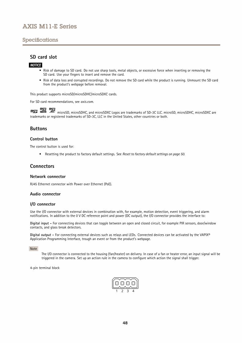
AXIS M11-E Series
Specifications
SD card slotNONONOTICETICETICE
• Risk of damage to SD card. Do not use sharp tools, metal objects, or excessive force when inserting or removing theSD card. Use your fingers to insert and remove the card.
• Risk of data loss and corrupted recordings. Do not remove the SD card while the product is running. Unmount the SD cardfrom the product’s webpage before removal.
This product supports microSD/microSDHC/microSDXC cards.
For SD card recommendations, see axis.com.
microSD, microSDHC, and microSDXC Logos are trademarks of SD-3C LLC. microSD, microSDHC, microSDXC aretrademarks or registered trademarks of SD-3C, LLC in the United States, other countries or both.
Buttons
Control button
The control button is used for:
• Resetting the product to factory default settings. See Reset to factory default settings on page 50.
Connectors
Network connector
RJ45 Ethernet connector with Power over Ethernet (PoE).
Audio connector
I/O connector
Use the I/O connector with external devices in combination with, for example, motion detection, event triggering, and alarmnotifications. In addition to the 0 V DC reference point and power (DC output), the I/O connector provides the interface to:
Digital input - For connecting devices that can toggle between an open and closed circuit, for example PIR sensors, door/windowcontacts, and glass break detectors.
Digital output - For connecting external devices such as relays and LEDs. Connected devices can be activated by the VAPIX®Application Programming Interface, trough an event or from the product’s webpage.
NoteThe I/O connector is connected to the housing (fan/heater) on delivery. In case of a fan or heater error, an input signal will betriggered in the camera. Set up an action rule in the camera to configure which action the signal shall trigger.
4-pin terminal block
48

AXIS M11-E Series
Specifications
Function Pin Notes Specifications
DC ground 1 0 V DC
DC output 2 Can be used to power auxiliary equipment.Note: This pin can only be used as power out.
12 V DCMax load = 25 mA
Digital Input 3 Connect to pin 1 to activate, or leave floating (unconnected)to deactivate.
0 to max 30 V DC
Digital Output 4 Internally connected to pin 1 (DC ground) when active,and floating (unconnected) when inactive. If used with aninductive load, e.g., a relay, connect a diode in parallel withthe load, to protect against voltage transients.
0 to max 30 V DC, open drain,100 mA
Example
1 DC ground2 DC output 12 V, max 25 mA3 Digital input4 Digital output
Power connector
2-pin terminal block for DC power input. Use a Safety Extra Low Voltage (SELV) compliant limited power source (LPS) with eithera rated output power limited to ≤100 W or a rated output current limited to ≤5 A.
49

AXIS M11-E Series
Troubleshooting
Troubleshooting
Reset to factory default settingsImportant
Reset to factory default should be used with caution. A reset to factory default resets all settings, including the IP address, tothe factory default values.
To reset the product to the factory default settings:
1. Disconnect power from the product.
2. Press and hold the control button while reconnecting power. See Product overview on page 46.
3. Keep the control button pressed for 15–30 seconds until the status LED indicator flashes amber.
4. Release the control button. The process is complete when the status LED indicator turns green. The product has been resetto the factory default settings. If no DHCP server is available on the network, the default IP address is 192.168.0.90.
5. Use the installation and management software tools to assign an IP address, set the password, and access the device.
The installation and management software tools are available from the support pages on axis.com/support.
You can also reset parameters to factory default through the device’s webpage. Go to Maintenance > Factory default and clickDefault.
Firmware optionsAxis offers product firmware management according to either the active track or the long-term support (LTS) tracks. Being on theactive track means continuously getting access to all the latest product features, while the LTS tracks provide a fixed platform withperiodic releases focused mainly on bug fixes and security updates.
Using firmware from the active track is recommended if you want to access the newest features, or if you use Axis end-to-end systemofferings. The LTS tracks are recommended if you use third-party integrations, which are not continuously validated against the latestactive track. With LTS, the products can maintain cybersecurity without introducing any significant functional changes or affectingany existing integrations. For more detailed information about Axis product firmware strategy, go to axis.com/support/firmware.
Check the current firmware versionFirmware is the software that determines the functionality of network devices. When you troubleshoot a problem, we recommendyou to start by checking the current firmware version. The latest firmware version might contain a correction that fixes yourparticular problem.
To check the current firmware:
1. Go to the device interface > Status.
2. See the firmware version under Device info.
Upgrade the firmwareImportant
Preconfigured and customized settings are saved when you upgrade the firmware (provided that the features are available inthe new firmware) although this is not guaranteed by Axis Communications AB.
ImportantMake sure the device remains connected to the power source throughout the upgrade process.
50

AXIS M11-E Series
Troubleshooting
NoteWhen you upgrade the device with the latest firmware in the active track, the product receives the latest functionalityavailable. Always read the upgrade instructions and release notes available with each new release before you upgrade thefirmware. To find the latest firmware and the release notes, go to axis.com/support/firmware.
1. Download the firmware file to your computer, available free of charge at axis.com/support/firmware.
2. Log in to the device as an administrator.
3. Go to Maintenance > Firmware upgrade and click Upgrade.
When the upgrade has finished, the product restarts automatically.
You can use AXIS Device Manager to upgrade multiple devices at the same time. Find out more ataxis.com/products/axis-device-manager.
Technical issues, clues, and solutionsIf you can’t find what you’re looking for here, try the troubleshooting section at axis.com/support.
Problems upgrading the firmware
Firmware upgrade failure If the firmware upgrade fails, the device reloads the previous firmware. The most common reasonis that the wrong firmware file has been uploaded. Check that the name of the firmware filecorresponds to your device and try again.
Problems after firmwareupgrade
If you experience problems after a firmware upgrade, roll back to the previously installed versionfrom the Maintenance page.
Problems setting the IP address
The device is located on adifferent subnet
If the IP address intended for the device and the IP address of the computer used to access thedevice are located on different subnets, you cannot set the IP address. Contact your networkadministrator to obtain an IP address.
The IP address is being usedby another device
Disconnect the Axis device from the network. Run the ping command (in a Command/DOS window,type ping and the IP address of the device):
• If you receive: Reply from <IP address>: bytes=32; time=10...this means that the IP address may already be in use by another device on the network.Obtain a new IP address from the network administrator and reinstall the device.
• If you receive: Request timed out, this means that the IP address is availablefor use with the Axis device. Check all cabling and reinstall the device.
Possible IP address conflictwith another device on thesame subnet
The static IP address in the Axis device is used before the DHCP server sets a dynamic address.This means that if the same default static IP address is also used by another device, there maybe problems accessing the device.
The device can’t be accessed from a browser
Can’t log in When HTTPS is enabled, ensure that the correct protocol (HTTP or HTTPS) is used when attemptingto log in. You may need to manually type http or https in the browser’s address field.
If the password for the user root is lost, the device must be reset to the factory default settings.See Reset to factory default settings on page 50.
51
AXIS M11-E Series
Troubleshooting
The IP address has beenchanged by DHCP
IP addresses obtained from a DHCP server are dynamic and may change. If the IP address has beenchanged, use AXIS IP Utility or AXIS Device Manager to locate the device on the network. Identifythe device using its model or serial number, or by the DNS name (if the name has been configured).
If required, a static IP address can be assigned manually. For instructions, go to axis.com/support.
Certificate error when usingIEEE 802.1X
For authentication to work properly, the date and time settings in the Axis device must besynchronized with an NTP server. Go to System > Date and time.
The device is accessible locally but not externally
To access the device externally, we recommend you to use one of the following applications for Windows®:
• AXIS Companion: free of charge, ideal for small systems with basic surveillance needs.• AXIS Camera Station: 30-day trial version free of charge, ideal for small to mid-size systems.
For instructions and download, go to axis.com/vms.
Problems with streaming
Multicast H.264 onlyaccessible by local clients
Check if your router supports multicasting, or if you need to configure the router settings betweenthe client and the device. You might need to increase the TTL (Time To Live) value.
No multicast H.264displayed in the client
Check with your network administrator that the multicast addresses used by the Axis deviceare valid for your network.
Check with your network administrator to see if there is a firewall that prevents viewing.
Poor rendering of H.264images
Ensure that your graphics card uses the latest driver. You can usually download the latest driversfrom the manufacturer’s website.
Color saturation is differentin H.264 and Motion JPEG
Modify the settings for your graphics adapter. Go to the adapter’s documentation for moreinformation.
Lower frame rate thanexpected
• See Performance considerations on page 52.• Reduce the number of applications running on the client computer.• Limit the number of simultaneous viewers.• Check with the network administrator that there is enough bandwidth available.• Lower the image resolution.
Can't select H.265 encodingin live view
Web browsers don’t support H.265 decoding. Use a video management system or applicationthat supports H.265 decoding.
Performance considerationsWhen setting up your system, it is important to consider how various settings and situations affect the performance. Some factorsaffect the amount of bandwidth (the bitrate) required, others can affect the frame rate, and some affect both. If the load on theCPU reaches its maximum, this also affects the frame rate.
The following factors are the most important to consider:
• High image resolution or lower compression levels result in images containing more data which in turn affects thebandwidth.
• Rotating the image in the GUI will increase the product's CPU load.
• Access by large numbers of Motion JPEG or unicast H.264 clients affects the bandwidth.
• Access by large numbers of Motion JPEG or unicast H.265 clients affects the bandwidth.
• Simultaneous viewing of different streams (resolution, compression) by different clients affects both frame rate andbandwidth.
52

AXIS M11-E Series
Troubleshooting
Use identical streams wherever possible to maintain a high frame rate. Stream profiles can be used to ensure thatstreams are identical.
• Accessing Motion JPEG and H.264 video streams simultaneously affects both frame rate and bandwidth.
• Accessing Motion JPEG and H.265 video streams simultaneously affects both frame rate and bandwidth.
• Heavy usage of event settings affects the product’s CPU load which in turn affects the frame rate.
• Using HTTPS may reduce frame rate, in particular if streaming Motion JPEG.
• Heavy network utilization due to poor infrastructure affects the bandwidth.
• Viewing on poorly performing client computers lowers perceived performance and affects frame rate.
• Running multiple AXIS Camera Application Platform (ACAP) applications simultaneously may affect the frame rate andthe general performance.
Need more help?
Useful links
• How to assign an IP address and access your device
Contact support
Contact support at axis.com/support.
53

User Manual Ver. M5.3AXIS M11-E Series Date: January 2022© Axis Communications AB, 2019 - 2022 Part No. T10140813