User Manual - 4-Axis CNC Motherboard - SourceRabbit
18
4-Axis CNC Motherboard User Manual Printed Circuit Board for ESP32 DevKitC Microcontroller Hosting Made in Greece Nikolaos Siatras 10 Serifou st., Holargos, 15562, Attica, Greece https://www.sourcerabbit.com
-
Upload
khangminh22 -
Category
Documents
-
view
1 -
download
0
Transcript of User Manual - 4-Axis CNC Motherboard - SourceRabbit

4-Axis CNC MotherboardUser Manual
Printed Circuit Board forESP32 DevKitC Microcontroller Hosting
Made in Greece
Nikolaos Siatras10 Serifou st., Holargos, 15562, Attica, Greecehttps://www.sourcerabbit.com

1
Disclaimer 2
Intended Purpose 2
General 3
Features & Specifications 4
At a glance 5
Basic Wiring 6Electromagnetic Shielded Box 7EMF filter and Emergency Stop Button 7Connection to 12V Power Supply 8Connecting Motor Controllers (Stepper Driver or Servo Driver) 9Connecting Terminal Switches and Probe / Tool Setter 10Simple Spindle Connection without Speed Control 11Connection for Spindle with VFD (Variable Frequency Drive) Speed Control 12
Help & Support 14
Security & Compliance 16
Declaration of Conformity EC 17

2
Disclaimer
Read and understand the contents of this user manual. Failure to read the manual mayresult in injury, degraded results or damage to the 4-Axis CNC Motherboard. Always ensurethat anyone using the 4-Axis CNC Motherboard knows and understands the contents of themanual.
The conditions or methods used for the assembling, handling, storing, using or disposing ofthe 4-Axis CNC Motherboard are beyond our control and may be beyond our knowledge.For these and other reasons, we do not take any responsibility and expressly disclaimliability for any losses, injuries, damages or costs arising from or in any way related to theassembly, handling, storage, use or disposal of the product. The information in thisdocument was obtained from sources we believe to be reliable. However, the information isprovided without any warranty, express or implied, as to the correctness.
GRBL software is provided to you as is, without warranty. There is no warranty for opensource GRBL software. The entire risk for the quality and performance of GRBL is on you.
Intended Purpose4-Axis CNC Motherboard is designed and manufactured to control Stepper Motors, ServoMotors, Spindles, Mist Pumps and Coolant Pumps of CNC machine tools, through specialcontrol software running on PC which is compatible with the GRBL firmware.
Copyright © 2021 SourceRabbit. All rights apply for the whole world. This manual is translated fromthe manufacturer's official language. No part of this publication, including images, may be reproducedand / or made public, either by printing, photocopying, microfilming or otherwise, without the priorwritten permission of the manufacturer.

3
General
The 4-Axis CNC Motherboard is a "small PC" that connects a personal PC with drivers ofstepper motors or servo that operate with Step / Direction. It is compatible with allmotor controllers on the market, can produce 120,000 pulses per second and is intendedfor controlling CNC 3 or 4 Axis CNC machine tools such as Router, Mills, Plasma and Lasers.
The 4-Axis CNC Motherboard hosts an ESP32-DevKitC-32D microcontroller manufactured byEspressif Systems which is always loaded with the latest 32-bit version of the GRBLfirmware. The ESP32-DevKitC-32D microcontroller has a dual core 240mhz, 520Kb ramprocessor and connects to the USB port of a modern personal computer (PC). TheESP32-DevKitC-32D microcontroller also has bluetooth and WiFi but you need to change theFirmware to enable it. We recommend that you leave the GRBL firmware as is anduse the USB port to communicate with the board from your computer as it is thesafest means of communication between PCs and CNC machine tools.
4
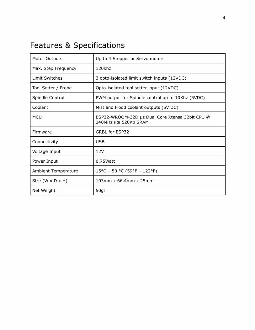
Features & SpecificationsMotor Outputs Up to 4 Stepper or Servo motors
Max. Step Frequency 120khz
Limit Switches 3 opto-isolated limit switch inputs (12VDC)
Tool Setter / Probe Opto-isolated tool setter input (12VDC)
Spindle Control PWM output for Spindle control up to 10Khz (5VDC)
Coolant Mist and Flood coolant outputs (5V DC)
MCU ESP32-WROOM-32D με Dual Core Xtensa 32bit CPU @240MHz και 520Kb SRAM
Firmware GRBL for ESP32
Connectivity USB
Voltage Input 12V
Power Ιnput 0.75Watt
Ambient Τemperature 15°C – 50 °C (59°F – 122°F)
Size (W x D x H) 103mm x 66.4mm x 25mm
Net Weight 50gr

5
At a glanceIn the image below you can see the top view of the 4-Axis CNC Motherboard. In the rest ofthe pages of this user manual you will see how to connect to the necessary electroniccomponents to complete your controller.

6
Basic WiringIn the following drawings you will see how to connect the necessary components tocomplete the controller of your machine tool with the 4-Axis CNC Motherboard. If you arenot familiar with the connection of electronic and electrical components, seek the help of aprofessional electronics or electrician.
CAUTION: Always use high quality power supplies that meet all CE regulations and haveprotection against short circuit, overload, overvoltage and overheating.
CAUTION: For your own safety do not make connections or other tasks to the controllerthat if it is connected to the mains. Always unplug the power supply before carryingout any work and wear protective goggles approved in accordance with EN 166 andAnsi Z87 +.
CAUTION: For your own safety you should ensure that your construction has a singlegrounding point, i.e. a point where all the GND and EARTH groundings of the electronicand electrical components will connect together. This point must end at EARTH ground.This point is usually the "chassis" of the control box, i.e. the body of the metal box thatcontains the electronic parts of the controller.
Tip: The 4-Axis CNC Motherboard has a Micro USB port. We recommend using a PanelMount USB Cable from B Female to Micro-B Male. With this you will be able to use highquality USB cables from A to B with electromagnetic shielding and ferrite at the ends. In thephoto below you will see a Panel Mount USB Cable - B Female to Micro-B Male

7
1. Electromagnetic Shielded Box
Although many users, for the hosting of their controller, use plastic boxes of electricalinstallations and in many cases do not cover their controllers at all, we recommendthat you use an electromagnetically shielded box to be sure of the performanceof all your electronic components..
The 4-Axis CNC Motherboard as well as all other components such as Stepper or ServoDrivers, and power supplies should be placed in an electromagnetically shieldedbox, i.e. a metal box whose body is connected to ground (Earth).
The electromagnetically shielded box prevents electromagnetic noise from enteringinside your controller. The most common problems from electromagnetic noise arisefrom Fluorescent Lamps, transformers of other devices, Plasma Cutters,Inverters and Spindles.
2. EMF filter and Emergency Stop Button
We recommend you install an EMF filter at the A/C input of your controller justbefore the Emergency Stop Button. The EMF filter will dramatically reduce the "dirty"current in the electricity grid. Dirty electricity is present in the power cords outside yourController when they contain frequencies other than the standard 60Hz frequency. These"bad" frequencies are generated by devices such as motors, welding machines, invertersand even transformers made of fluorescent lamps.
In the figure below you will see a typical EMF filter installation and Emergency StopButton

8
3. Connection to 12V Power Supply
In order for the 4-Axis CNC Motherboard to operate, a stabilized 12V DC powersupply, of at least 2A, must be connected to the VCC IN input, which must be properlygrounded. See the drawing below.
Tip: Always check if the power supply is properly grounded to the Earth with amultimeter before installation..
Tip: Always ensure good ventilation in the power supplies.

9
4. Connecting Motor Controllers (Stepper Driver or Servo Driver)
In the drawing below you will see the connection of a Stepper Driver that uses STEP(PUL) and DIR ports with the X-axis output of the 4-Axis CNC Motherboard. Theconnection for the other axes (Y, Z & A) is made in exactly the same way.
CAUTION: The motor controller (Stepper Driver) must have a common ground(Common Ground) with the 4-Axis CNC Motherboard. This is achieved simply byconnecting the GND of the power supply to the GND of the 4-Axis CNC Motherboard. Ifthe motor controller operates on A/C power then you should refer to the motor controlleroperating instructions to see how to connect.
Tip: To ensure maximum performance and isolation of electromagnetic noise, it isadvisable to use Twisted Pair Wire for STP and DIR connection.

10
5. Connecting Terminal Switches and Probe / Tool Setter
The 4-Axis CNC motherboard has 3 limit switches sockets and one socket for Probeor Tool Setter. All four sockets supply 12VDC voltage and are isolated withOptocouplers, which ensure isolation of the circuit from electromagnetic noise. In thefollowing drawing you will see the connection of a terminal switch to the LimXoutput, i.e. the connection of a terminal switch for the X axis of the CNC machine tool.The connection for the other axes (Y, Z & A) is made in exactly the same way.
CAUTION: The switches and the Probe / Tool Setter must be in NC (Normally Closed)state, ie normally closed. In normally closed switches, the contacts that connect theswitch are closed, which means that when they are not compressed the circuit is closed.
Tip: To ensure maximum performance and isolation of external electromagnetic noise, itis advisable to use Twisted Pair Wire or even better LIYCY signal cables to connectthe terminal switches and the Probe. This ensures maximum accuracy during theHoming Cycle.
Tip: In case you use Coolant Fluids, water or other liquids, we recommend usingwaterproof terminal switches with IP67 waterproofing index.

11
6. Simple Spindle Connection without Speed Control
In the following drawing you will see the connection of a high speed and precisionspindle, made by AMB Elektrik, without speed control, using a Solid State Relay.
CAUTION: The wiring is typical and may not fit all spindles. In any case you should seethe spindle manufacturer's instructions on how to make the correct connection.
CAUTION: Many low-quality spindles, such as the cheap wood-routers used by thehobby community, produce large amounts of electromagnetic pulses that can damageyour health as well as shorten the life of your electronics. Always make sure to usehigh quality CE certified spindles that comply with European CommunityElectromagnetic Compatibility Directives.

12
7. Connection for Spindle with VFD (Variable Frequency Drive)Speed Control
In the following drawing you see how to connect the 4-Axis CNC Motherboard to a VFD(Variable Frequency Drive) which receives voltage signals 0V to 10V for speedadjustment. To convert the PWM signal to 0V to 10V you have to use a PWM toVoltage Converter Module 0% -100% to 0-10V. There are VFDs that do not need toconvert PWM to 0V to 10V. In this case the PWM output of the 4-Axis CNC Motherboardis connected directly to the VFD. In either case you should see the VFD manufacturer'sinstructions on how to make the correct connection.
CAUTION: The wiring is typical and may not match all VFDs (Variable FrequencyDrives). In either case you should see the VFD manufacturer's instructions on how tomake the correct connection.

13
8. Flood Coolant Pump Connection
In the following drawing you see a typical coolant pump connection using a Solid StateRelay. The connection for the Mist Coolant system to the Mist pin of the 4-Axis CNCMotherboard is done in exactly the same way.
CAUTION: Always use coolant pumps that meet CE standards

14
Help & SupportThere are some potential problems that you may encounter when using the 4-Axis CNCMotherboard. If you are presented with any of these, you can easily deal with it with thehelp you will find below.
● The PC does not "see" the 4-Axis CNC Motherboard
This problem often occurs in older versions of Microsoft Windows and is due to thelack of Hardware Drivers for USB to UART Bridge used by the 4-Axis CNCMotherboard. In this case you should contact us to direct you or install the Driversfor you on your PC.
● USB connection drops during operation
The most common problem faced by CNC machine tool operators is the disconnectionof the controller from the PC during operation. This problem is usually caused byexternal electromagnetic noises.
Solutions to the problem:● Always use a USB cable with electromagnetic shielding, no longer than
1.8m and which has ferrite at both ends● Install an EMF filter at the input of your controller● Install an EMF filter at the input of the Spindle current (if any)● Install an EMF filter at the VFD power input (if any)● Install an EMF filter at the Plasma Cutter power input (if any)● Install an EMF filter at the input of the power supply of the laser source (if
any)● Install an EMF filter at the inlet of the coolant pump (if any)
Tip: If you use a laptop to operate your machine tool then you should know thateconomical Laptops do not have good electromagnetic shielding. Laptopmanufacturers, in their attempt to make laptops light and user-friendly, use onlyplastic to create the computer case. The plastic offers no electromagneticshielding. We recommend that you use a desktop computer to control your machinetool. The electronics of desktop computers are housed in a metal box(tower) that provides quite satisfactory electromagnetic shielding.
Tip: If you are using VFD (Variable Frequency Drive) to control motors such as thespindle motor, then the spindle motor with the VFD should be connected with a cablethat has electromagnetic shielding and ferrites..
Tip: Keep devices such as Plasma Cutters and VFDs (Variable Frequency Drives) asfar away as possible from the 4-Axis CNC Motherboard and the other electronic

15
components of the controller. Cheap devices of this type do not have goodelectromagnetic shielding as their housing is made of plastic, while in mostcases their manufacturers do not integrate an EMF filter. These devices emit largeamounts of electromagnetic noise that affects USB devices and can cause problemseven on PC hard drives.
In the photo below you will see a typical VFD installation (left) for the spindle speedadjustment and a toroidal type transformer (right) for the power supply of steppermotors. As you will see, there is a separate EMF filter for the VFD and thetransformer, while the cable that connects the VFD to the spindle is shielded and hasferrites.

16
Security & Compliance● Electromagnetic Compatibility (EMC)
The 4-Axis CNC motherboard can cause and receive electromagnetic interference, sothe user may need to take appropriate action. In very rare cases the 4-Axis CNCMotherboard may lose its USB connection due to electrostatic discharge (ESD). TheUSB connection can be fully restored after restarting the PC.
● Electrical safetyThe 4-Axis CNC Motherboard operates on 12V DC. Therefore the 4-Axis CNCMotherboard is in the scope of the low-voltage directive.
● General safety informationThe 4-Axis CNC motherboard is not intended for use by persons (including children)with reduced physical and / or mental abilities or lack of experience and knowledge,unless under the supervision or guidance of a person responsible for their safety.
Children must be under constant supervision when using the machine tool.
The above information is believed to be correct, but is not intended to cover all casesand will only be used as a guide.
The conditions or methods used for assembling, handling, storage, use or disposal ofthe device are beyond our control and may be beyond our knowledge. For this andother reasons, we do not assume responsibility and expressly disclaim liability forloss, injuries, damage, or expense arising out of or in any way connected with theassembly, handling, storage, use or disposal of the product.

17
Declaration of Conformity EC