Aviation Mechanics Bulletin May-June 1997 - Flight Safety ...
20
MAY–JUNE 1997 FLIGHT SAFETY FOUNDATION Aviation Mechanics Bulletin Fatigue Crack Leads to MD-83 Left Main Landing Gear Collapse on Rollout Attachment Trunnion Torque Links (shimmy damper not shown) Cylinder Piston/Axle Assembly FORWARD ➯ Approximate Line of Fracture
-
Upload
khangminh22 -
Category
Documents
-
view
0 -
download
0
Transcript of Aviation Mechanics Bulletin May-June 1997 - Flight Safety ...
MAY–JUNE 1997
F L I G H T S A F E T Y F O U N D A T I O N
Aviation Mechanics Bulletin
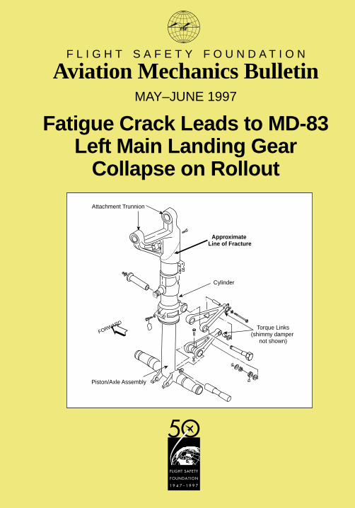
Fatigue Crack Leads to MD-83Left Main Landing Gear
Collapse on Rollout
Attachment Trunnion
Torque Links(shimmy damper
not shown)
Cylinder
Piston/Axle Assembly
FORWARD
➯
Approximate Line of Fracture
F L I G H T S A F E T Y F O U N D A T I O N
Aviation Mechanics BulletinDedicated to the aviation mechanic whose knowledge,craftsmanship and integrity form the core of air safety.
Robert A. Feeler, editorial coordinator
Fatigue Crack Leads to MD-83Left Main Landing Gear Collapse on Rollout ..............................................1
News & Tips ..................................................................................................8
Maintenance Alerts ........................................................................................9
New Products ............................................................................................. 12
May–June 1997 Vol. 45 No. 3
AVIATION MECHANICS BULLETINCopyright © 1997 FLIGHT SAFETY FOUNDATION INC. ISSN 0005-2140
Suggestions and opinions expressed in FSF publications belong to the author(s) and arenot necessarily endorsed by Flight Safety Foundation. Content is not intended to take theplace of information in company policy handbooks and equipment manuals, or to supersedegovernment regulations.
Staff: Roger Rozelle, director of publications; Rick Darby, senior editor; Glenn Orthmann,editorial assistant; Todd Lofton, editorial consultant; Karen K. Ehrlich, production coordinator;Ann L. Mullikin, assistant production coordinator; and David Grzelecki, librarian, Jerry LedererAviation Safety Library.
Subscriptions: US$35 (U.S.-Canada-Mexico), US$40 Air Mail (all other countries), six issuesyearly. • Include old and new addresses when requesting address change. • Flight SafetyFoundation, 601 Madison Street, Suite 300, Alexandria, VA 22314 U.S. • Telephone: (703)739-6700 • Fax: (703) 739-6708
We Encourage ReprintsArticles in this publication may be reprinted in the interest of aviation safety, in whole or inpart, in all media, but may not be offered for sale or used commercially without the expresswritten permission of Flight Safety Foundation’s director of publications. All reprints mustcredit Flight Safety Foundation, Aviation Mechanics Bulletin, the specific article(s) and theauthor(s). Please send two copies of the reprinted material to the director of publications. Thesereprint restrictions apply to all Flight Safety Foundation publications.
What’s Your Input?In keeping with FSF’s independent and nonpartisan mission to disseminate objective safetyinformation, Foundation publications solicit credible contributions that foster thought-provokingdiscussion of aviation safety issues. If you have an article proposal, a completed manuscript ora technical paper that may be appropriate for Aviation Mechanics Bulletin, please contact thedirector of publications. Flight Safety Foundation assumes no responsibility for submittedmaterial. The publications staff reserves the right to edit all published submissions. TheFoundation buys all rights to published manuscripts. Payment is made to authors uponpublication. Contact the Publications Department for more information.
Fatigue Crack Leads to MD-83Left Main Landing Gear
Collapse on Rollout
On April 27, 1995, a McDonnell Dou-glas MD-83, owned and operated byAirtours International Aviation(Guernsey), landed at Manchester (En-gland) Airport after a routine flightfrom Las Palmas, Canary Islands.Touchdown was normal and both mainwheels contacted the runway about thesame time. During the rollout, thespoilers deployed automatically, andreverse thrust was selected. Brakeswere initially applied at about 161 ki-lometers per hour [kph (87 knots)]. At115 kph (62 knots), a maximum de-celeration of 0.416 G was recorded bythe digital flight data recorder.
As the aircraft slowed below 111 kph(60 knots), the captain joined the firstofficer, the pilot flying, on the brakes.Soon thereafter, there was a loud bangand the sound of tearing metal, and
the left main landing gear (MLG)collapsed.
There were no serious injuries to crewor passengers. Damage to the air-frame included scraping of the leftwing tip, outboard flaps and slats.Several flap hinges were distorted.The primary wing structure, includ-ing the integral fuel tank, was intact.
The U.K. Air Accidents InvestigationBranch (AAIB) found that the causeof the accident was the failure of theforged landing-gear oleo (hydraulic)cylinder at a point just below its at-tachment trunnions; that the cylinderfailure resulted from a visually un-detectable fatigue crack in its forwardface; and that the crack began withmultiple small fatigue originsassociated with grit-blasting during
FSF Editorial Staff
FLIGHT SAFETY FOUNDATION • AVIATION MECHANICS BULLETIN • MAY–JUNE 1997 1
manufacture, but had been exacerbat-ed over time by self-sustaining vibra-tions of the MLG.
Although the company called for nobraking above 148 kph (80 knots), un-less safety dictated otherwise, thecrew’s actions were not found to havecontributed to the accident.
The MD-80 series are short- to me-dium-range transport aircraft withtwo Pratt & Whitney JT8D turbofanengine pods mounted on either sideof the rear fuselage.
The accident aircraft’s landing weightwas 57,290 kilograms (126,300pounds), which did not exceed theMD-83 maximum landing weight of63, 277 kilograms (130,500 pounds).The aircraft was delivered in 1990,and at the time of the accident had atotal of 18,236 flight hours and 6,386landings.
The MLG for the MD-80 series ismanufactured with the same forgingdies as the MLG of its predecessor,the McDonnell Douglas DC-9. Toallow for the greater capacity andweight of the MD-80, the MLG con-struction material was changed fromthe original “Hy-TUF” specificationAMS 6418 (used in the DC-9) toultrahigh-tensile 300M steel.
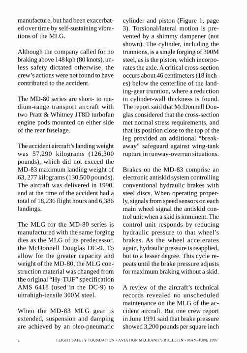
When the MD-83 MLG gear isextended, suspension and dampingare achieved by an oleo-pneumatic
cylinder and piston (Figure 1, page3). Torsional/lateral motion is pre-vented by a shimmy dampener (notshown). The cylinder, including thetrunnions, is a single forging of 300Msteel, as is the piston, which incorpo-rates the axle. A critical cross-sectionoccurs about 46 centimeters (18 inch-es) below the centerline of the land-ing-gear trunnion, where a reductionin cylinder-wall thickness is found.The report said that McDonnell Dou-glas considered that the cross-sectionmet normal stress requirements, andthat its position close to the top of theleg provided an additional “break-away” safeguard against wing-tankrupture in runway-overrun situations.
Brakes on the MD-83 comprise anelectronic antiskid system controllingconventional hydraulic brakes withsteel discs. When operating proper-ly, signals from speed sensors on eachmain wheel signal the antiskid con-trol unit when a skid is imminent. Thecontrol unit responds by reducinghydraulic pressure to that wheel’sbrakes. As the wheel acceleratesagain, hydraulic pressure is reapplied,but to a lesser degree. This cycle re-peats until the brake pressure adjustsfor maximum braking without a skid.
A review of the aircraft’s technicalrecords revealed no unscheduledmaintenance on the MLG of the ac-cident aircraft. But one crew reportin June 1991 said that brake pressureshowed 3,200 pounds per square inch
2 FLIGHT SAFETY FOUNDATION • AVIATION MECHANICS BULLETIN • MAY–JUNE 1997

(PSI)–3,300 PSI during initial taxi;and, when the brakes were first ap-plied, the MLG experienced a “sav-age snatch/[shudder],” after whichthe brake pressure dropped into thenormal 2,500 PSI–3,000 PSI range.Brake pressures and cylinders werechecked subsequently and reported tobe normal.
Landing gear are affected by twokinds of vibrations: (1) transient
vibrations, which are caused bybumps in the runway or suddenchanges in braking and are usuallybenign; and (2) self-sustaining vibra-tions, which are persistent, have veryhigh amplitudes and are capable ofdamaging the aircraft. Gear walkingis in the second category.
When brakes are applied, the MLGflexes rearward; when the hydraulicpressure is relieved by the antiskid
Figure 1
MD-80 Series Main Landing Gear Oleo Strut
Source: U.K. Air Accidents Investigation Branch
Attachment Trunnion
Torque Links(shimmy damper
not shown)
Cylinder
Piston/Axle Assembly
FORWARD
➯
Approximate Line of Fracture
FLIGHT SAFETY FOUNDATION • AVIATION MECHANICS BULLETIN • MAY–JUNE 1997 3

system, the MLG leg springs forward.This action rapidly accelerates thewheel, signaling the antiskid systemto reapply the brakes. This causes thewheel to flex rearward again, and soon.
Gear walking is “a dynamic couplingof the characteristics of the antiskidsystem and the natural fore-and-aftfrequency of the MLG leg,” the reportsaid, “and can be additionally affect-ed by such factors as tire pressures andbleed condition of the brake systemhydraulics ... [74 kph (40 knots)] is theknown ‘critical’ condition at which[gear] walking can occur.”
The component that failed on the MLGwas the left-hand cylinder. Inspectionrevealed a crack five millimeters (0.19inch) long by 1.25 millimeters (0.049inch) deep on the front face of an oth-erwise typical cylinder. According tothe report, the crack almost certainlywas not detectable visually.
On first examination, the fractureseemed to have the characteristics ofbrittle overload fracture. Closer ex-amination revealed the presence of asmall, brown, crescent-shaped areathat resembled a pre-existing defect.A metallurgist identified the defect ascharacteristic of fatigue, and said that,though relatively small, it was prob-ably responsible for the failure of theleft MLG leg. It was not possible toperform a striation count, whichmight have revealed the number of
stress cycles over which the fatiguecrack had developed.
Mathematical tests using data suppliedby McDonnell Douglas concludedthat, during the accident landing, thetouchdown did not contribute to thesubsequent failure of the cylinder, butthat heavy braking on rollout createdstresses approaching two-thirds of themaximum stress for the material.
Stress analysis commissioned by theAAIB based on recorded flight datasubstantiated these findings, indicat-ing that the failure of the left MLGcylinder was not precipitated in anyway by the operating crew’s execu-tion of the accident landing; and thateven though the subsequent brakingeffort fell within the McDonnell Dou-glas definition of “heavy,” an un-cracked cylinder should have beencapable of withstanding an almostlimitless number of such brake appli-cations without failure.
The root cause of the fracture, thereport said, “was multiple fatigue or-igins associated with the rough anduneven surface finish on the outsideof the cylinder.” These surface flawswere the result of grit-blasting to pre-pare the steel surface of the cylinderfor high-current density cadmiumplating. Small particles of aluminumoxide, the grit-blasting agent, werefound trapped in surface folds be-neath the cadmium plating, and therewere microscopic fatigue cracks
4 FLIGHT SAFETY FOUNDATION • AVIATION MECHANICS BULLETIN • MAY–JUNE 1997
apparently growing from some of thesharpest and deepest folds.
The weakness generated by grit-blasting was likely to have been in-creased early in the aircraft’s life bygear walking.
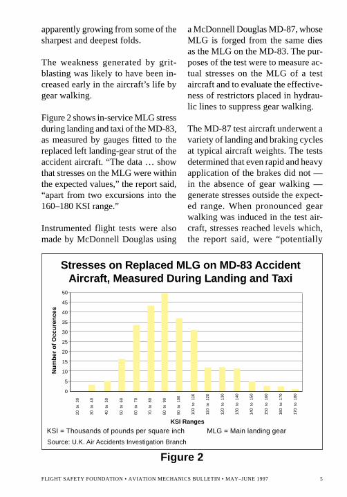
Figure 2 shows in-service MLG stressduring landing and taxi of the MD-83,as measured by gauges fitted to thereplaced left landing-gear strut of theaccident aircraft. “The data … showthat stresses on the MLG were withinthe expected values,” the report said,“apart from two excursions into the160–180 KSI range.”
Instrumented flight tests were alsomade by McDonnell Douglas using
a McDonnell Douglas MD-87, whoseMLG is forged from the same diesas the MLG on the MD-83. The pur-poses of the test were to measure ac-tual stresses on the MLG of a testaircraft and to evaluate the effective-ness of restrictors placed in hydrau-lic lines to suppress gear walking.
The MD-87 test aircraft underwent avariety of landing and braking cyclesat typical aircraft weights. The testsdetermined that even rapid and heavyapplication of the brakes did not —in the absence of gear walking —generate stresses outside the expect-ed range. When pronounced gearwalking was induced in the test air-craft, stresses reached levels which,the report said, were “potentially
Figure 2
KSI = Thousands of pounds per square inch MLG = Main landing gear
Stresses on Replaced MLG on MD-83 AccidentAircraft, Measured During Landing and Taxi
KSI Ranges
50
45
40
35
30
25
20
15
10
5
0
20 t
o 3
0
Nu
mb
er o
f O
ccu
ren
ces
30 t
o 4
0
40 t
o 5
0
50 t
o 6
0
60 t
o 7
0
70 t
o 8
0
80 t
o 9
0
90 t
o 1
00
100
to 1
10
110
to 1
20
120
to 1
30
130
to 1
40
140
to 1
50
150
to 1
60
160
to 1
70
170
to 1
80
Source: U.K. Air Accidents Investigation Branch
FLIGHT SAFETY FOUNDATION • AVIATION MECHANICS BULLETIN • MAY–JUNE 1997 5
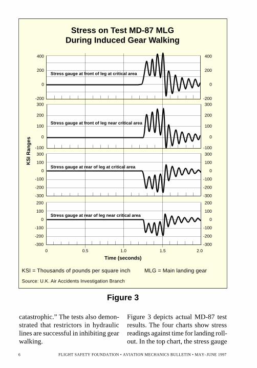
catastrophic.” The tests also demon-strated that restrictors in hydrauliclines are successful in inhibiting gearwalking.
Figure 3 depicts actual MD-87 testresults. The four charts show stressreadings against time for landing roll-out. In the top chart, the stress gauge
Stress on Test MD-87 MLGDuring Induced Gear Walking
Figure 3
400
200
0
-200300
200
100
0
-100
300
100
0
-100
-200
-300
200
100
0
-100
-200
-300
0 0.5 1.0 1.5 2.0
Time (seconds)
KS
I Ran
ges
Stress gauge at front of leg at critical area
Stress gauge at front of leg near critical area
Stress gauge at rear of leg at critical area
Stress gauge at rear of leg near critical area
200
100
0
-100
-200
-300
300
100
0
-100
-200
-300
300
200
100
0
-100
400
200
0
-200
KSI = Thousands of pounds per square inch MLG = Main landing gear
Source: U.K. Air Accidents Investigation Branch
6 FLIGHT SAFETY FOUNDATION • AVIATION MECHANICS BULLETIN • MAY–JUNE 1997
was fitted to the front of the leg atthe critical (crack) area. As can beseen, gear walking was induced atabout 1.3 seconds. It lasted for lessthan half a second, but during thattime, stress on the MLG leg reachedfour times normal levels. The secondchart shows the same data for a gaugeslightly displaced from the criticalarea. The bottom two charts depict theresults from gauges located at the rearof the leg.
The report said, “The aircraft manu-facturer was clearly aware of the ‘gearwalking’ phenomenon on the MD-80series prior to the accident investiga-tion, but was apparently unaware ofthe high stresses generated by ‘gear-walk mode 2,’ which is defined as aviolent event with stress levels of [272KSI] or more ... .”
As a result of this accident, and inview of the possibility that occurrenc-es of gear walking may have goneunrecorded, the U.S. Federal AviationAdministration (FAA) and McDon-nell Douglas required inspections ofMD-80 series aircraft to check forcracking of the MLG cylinder in acritical area.
Alert Service Bulletin (ASB) MD-80-32A286, issued by McDonnell Dou-glas on Sept. 11, 1995, called formagnetic-particle and fluorescentdye-penetrant crack detection on theMLG cylinders on all MD-80 series
aircraft. FAA Airworthiness Directive(AD) 95-22-06, effective Nov. 8,1995, made the requirements of ASBMD-80-32A286 mandatory for allaircraft on the U.S. register.
AD 96-01-09 subsequently mandat-ed the fitting of in-line hydraulic re-strictors on all MD-80 series aircraftMLG.
The AAIB report recommended thatthe FAA review its AD 95-22-06 toconsider requiring repeat inspections,— even after restrictors have beeninstalled — of landing gear that wasever operated without restrictors.
The accident report also recommend-ed that the FAA and the U.K. CivilAviation Authority coordinate a studyto develop surface treatment forhighly loaded, high-tensile steelcomponents that will achieve fatigueresistance and surface protectionwithout introducing surface stress-raising features.♦
Editorial Note: This article is derivedfrom Aircraft Accident Report 1/97(EW/C95/4/2), Report on the Acci-dent to Douglas Aircraft CompanyMD-83, G-DEVR at ManchesterAirport on 27 April 1995, preparedby the Air Accidents InvestigationBranch (AAIB), U.K. Department ofTransport, Defence Research Agen-cy, Farnborough, Hampshire, GU146TD, England.
FLIGHT SAFETY FOUNDATION • AVIATION MECHANICS BULLETIN • MAY–JUNE 1997 7
Airframe & EngineMaintenance/RepairConference Set for
Vancouver
The Society of Automotive EngineersInc. (SAE) will bring togetheran estimated 400 attendees and 25 ex-hibitors for its Airframe & EngineMaintenance/Repair Conference &Exposition (AEMR) on Aug. 6–10,1997. Vancouver, British Columbia,Canada, will be the location; the ex-act venue has not yet been set.
Topics to be discussed at theconference will include continued air-worthiness, nondestructive testingsystems and equipment, advancedplating, and metal-finishing equip-ment and services.
For further information, contact: SAEProfessional Development, 400 Com-monwealth Drive, Warrendale, PA15096-0001 U.S. Telephone: (412)772-7148; Fax: (412) 776-4955.
FAA ConsidersChanging
Aircraft-mechanicTraining Requirements
The U.S. Federal Aviation Adminis-tration (FAA) is considering (1) re-placing the present airframe and
powerplant (A&P) license withan aircraft maintenance technician(AMT) license; and (2) requiring anadditional year of training to quali-fy for the transport (AMT-T) rating.
Under the new system, earning theequivalent of two-year A&P willtake three years. Nevertheless, currentholders of A&P certificates wouldautomatically become AMT-Ts.
Other changes under considerationinclude instituting biannual (everytwo years) renewal of certificates andrecurrent training.
FAA Proposes OneRecord-keeping
Standard forAll Aircraft
A soon-to-be-released U.S. FederalAviation Administration (FAA)Notice of Proposed Rulemaking(NPRM) is expected to require a sin-gle record-keeping standard for allU.S.-registered aircraft owners andoperators, regardless of what U.S.Federal Aviation Regulations part theaircraft operates under (Part 91, 121or 135).
One intended benefit of the proposedchange would be more accurateprojections of maintenance needsand downtime. Another anticipated
NEWS & TIPS
8 FLIGHT SAFETY FOUNDATION • AVIATION MECHANICS BULLETIN • MAY–JUNE 1997

benefit would be more efficientmaintenance record keeping, whichcould facilitate the sale of aircraft.
At the time of this writing, there isno firm release date on the NPRM.
Aircraft MaintenanceSafety Course for
Managers andSupervisors Scheduled
The Southern California SafetyInstitute will offer Aircraft Mainte-nance Safety, a course for maintenancemanagers or supervisors and safetymanagers, on Oct. 27–31, 1997, inAlbuquerque, New Mexico, U.S.
The course focuses on basic accidentprevention on the flight line and inthe hangar and maintenance shop.
Regulatory and administrative re-quirements and environmental issuesare also addressed.
Topics will include hangar and main-tenance shop safety; occupationalsafety and health; right-to-know re-quirements; environmental protection;storage and handling of hazardous ma-terials; regulatory requirements; andsafety program administration. Therewill be 36 hours of classroom instruc-tion, and students will receive a text-book, lecture outlines, additionalreference material and a certificate ofcompletion.
For more information, contact:Southern California Safety Institute,3838 Carson Street, Suite 105, Tor-rance, CA 90503-6705 U.S. Tele-phone: (310) 540-2612; Fax: (310)540-0532.♦
MAINTENANCE ALERTS
Twin-turbochargedCessnas Remain
Vulnerable toExhaust-system Failures
In-flight exhaust failures in twin-turbocharged Cessnas, a problem firstaddressed by U.S. Federal AviationAdministration (FAA) AirworthinessDirective (AD) 75-23-08 in 1975,
have increased in recent months,perhaps because of the long servicelife of existing exhaust-systemcomponents.
Exhaust-system failure in twin-turbocharged Cessnas can trigger achain of events that leads to enginefuel starvation or a fuel-fed fire thatburns through the front wing spar andcauses the wing to fail. Cessna
FLIGHT SAFETY FOUNDATION • AVIATION MECHANICS BULLETIN • MAY–JUNE 1997 9
owners or maintenance techniciansshould conduct a careful visual in-spection and pressure test of theaircraft’s exhaust system.
Faulty Repair ofB-747 Wing-panelHoneycomb Cells
Results inUnscheduled Landing
During the climb phase of a Boeing747-236B flight from London, En-gland, to Delhi, India, the flight crewnoticed a moderate airframe vibrationthat began when the flaps were raisedfrom five degrees to one degree. Thevibration continued when the flapswere raised from one degree to zerodegrees, became “slight” after flaps-up, and returned to moderate as theaircraft passed through 8,083 meters(26,500 feet) at Mach 0.83. The vi-bration reduced once again after theplane leveled off at 8,235 meters(27,000 feet), and the speed was re-duced to 574 kilometers per hour (310knots) indicated airspeed.
The captain decided to dump fuel andreturn to Heathrow Airport, London,where the landing was uneventful.
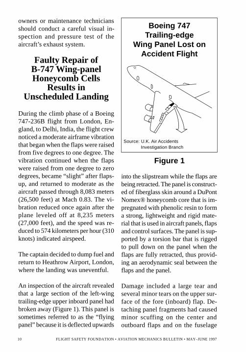
An inspection of the aircraft revealedthat a large section of the left-wingtrailing-edge upper inboard panel hadbroken away (Figure 1). This panel issometimes referred to as the “flyingpanel” because it is deflected upwards
into the slipstream while the flaps arebeing retracted. The panel is construct-ed of fiberglass skin around a DuPontNomex® honeycomb core that is im-pregnated with phenolic resin to forma strong, lightweight and rigid mate-rial that is used in aircraft panels, flapsand control surfaces. The panel is sup-ported by a torsion bar that is riggedto pull down on the panel when theflaps are fully retracted, thus provid-ing an aerodynamic seal between theflaps and the panel.
Damage included a large tear andseveral minor tears on the upper sur-face of the fore (inboard) flap. De-taching panel fragments had causedminor scuffing on the center andoutboard flaps and on the fuselage
Figure 1
Boeing 747Trailing-edge
Wing Panel Lost onAccident Flight
Source: U.K. Air AccidentsInvestigation Branch
10 FLIGHT SAFETY FOUNDATION • AVIATION MECHANICS BULLETIN • MAY–JUNE 1997
flap was brought into contact with thebroken trailing edge of the panel.
Panel RepairedIn AccordanceWith Manual
The airline stated that prior to Sep-tember 1995 the panel had been re-paired in accordance with the BoeingStructural Repair Manual (SRM). InOctober 1995, a design deviation au-thority (DDA) was granted, whichallowed the aircraft to remain in ser-vice with a crack that had appearedfrom the SRM-based repair. [DDAis a U.K. Civil Aviation Authority(CAA)-approved procedure that per-mits the airline to design and imple-ment repairs that constitute minordeviations from the aircraft manufac-turer’s process or drawings.] Underthe DDA, the crack was marked withink, to check for any further propa-gation, and was taped to preventmoisture entry. The DDA also calledfor reinspection of the panel every190 flight hours and repair of thecrack in December 1995.
An additional DDA was issued onOct. 9, 1995. It called for a tempo-rary repair of the delamination thathad occurred around the original re-pair, as well as the cracking. The ad-ditional DDA also called for a checkof the repair every 540 flight hoursand terminating action in December1996, which introduced a redesignedand strengthened panel.
paint aft. Beneath the panel, one ofthe torsion-bar struts had failed fromoverloading.
Damage ResultedFrom Partially
Filled Honeycomb
Examination of the recovered panelindicated that the failure had begun inthe bond between the upper skin andthe core and that the failure was asso-ciated with previous repairs. A closerexamination of the section of the pan-el containing the repairs showed aspanwise wrinkle in the upper fiber-glass skin, caused by a partially filledregion of the honeycomb.
Filler had apparently been added tothat region of the honeycomb, but hadnot penetrated to the full depth of thehoneycomb cells. A subsequent repairhad been made involving a honey-comb insert. But no attempt had beenmade to join the inserted plug to thesurrounding core. All repairs hadbeen carried out using cold-settingadhesives.
It was concluded by the U.K. Air Ac-cidents Investigation Branch (AAIB)that the failure was the result of a lo-calized change in stiffness in bend-ing caused by the filler in the core. Itis probable that pieces of the paneldetached after the aircraft becameairborne, and that additional minordamage occurred as the flaps were re-tracted and the forward edge of the
FLIGHT SAFETY FOUNDATION • AVIATION MECHANICS BULLETIN • MAY–JUNE 1997 11
Deviations from SRMWere Discontinued
As a result of this incident, a specialcheck was instituted by the carrier toinspect and repair, as required, alltrailing-edge flying panels of all ofits B-747 aircraft. Aircraft with SRM-based repairs were to be inspectedwithin one month; all other aircraftwere to be inspected as soon as pos-sible. Deviations from the SRM
concerning the panel were discontin-ued and the SRM was amended topermit no cracks.
The airline also publicized the prob-lem of the damaged panels in itsin-house technical newsletter and,considering that panel damage couldalso result from maintenance person-nel walking on the panels during in-spection and servicing, had all panelsplacarded “No Step.”♦
NEW PRODUCTS
Hand-held PrinterAids Wire
Identification
A product upgrade designed to im-prove the production speed and legi-bility of labels for wires in complexelectrical, telecommunications, elec-tronic and pneumatic systems hasbeen introduced by Brady USA Inc.
The I.D. PRO™ Plus, an outgrowthof I.D. PRO, is a portable, hand-heldprinter that can be used in markingwires and cables in the shop, and forpreprinting labels for applicationsincluding quality assurance,maintenance, calibration and assetidentification.
The I.D. PRO Plus can print on rollsof three widths: 1.3 centimeters (0.5inch), 2.5 centimeters (one inch) and
3.8 centimeters (1.5 inches). A self-adjusting print head allows printingon self-laminating vinyl, clothand heat-shrinkable tubing. The unitweighs 0.7 kilograms (1.6 pounds).
The I.D. PRO Plus is said to improveon the I.D. PRO by:
• Increasing the print speed by 43percent;
• Improving print quality and add-ing a boldface option;
• Providing automatic label serial-ization that automatically ad-vances label numbers by onedigit in a series preset by theuser; and,
• Allowing eight lines of variabletext.
For further information, contact:Brady Response Center, P.O. Box
12 FLIGHT SAFETY FOUNDATION • AVIATION MECHANICS BULLETIN • MAY–JUNE 1997

meters (three inches to 4.8 feet) andare offered in standard, releaseable,screw-mount, push-mount, beaded,ladder and marker tags in one-, two-and three-tie versions.
Nelco custom ties are priced accord-ing to style, size and imprinting re-quirements. For further information,contact: Nelco Products, 77 AccordPark Drive, Norwell, MA 02061 U.S.Telephone: (800) 346-3562 (UnitedStates and Canada); (617) 871-3115;Fax: (617) 871-3117.
New Tool Box HasSliding Trays for
Small Parts, StorageCompartment
For Bulky Items
The new Hand Box with SlidingTrays by Sears Craftsman® providesstorage for both small parts and bulkytools. The product provides 20,795
3064, Cedar Rapids, IA 52406 U.S.Telephone: (800) 216-8396 (UnitedStates and Canada); (414) 358-6600.
Cable Ties OfferCustomized
Identification orWarnings
Nelco Products Inc. has introducedcable ties that can provide permanentidentification, or a message such as awarning, on the cables to which theyare attached. The ties are custom madefrom a wide variety of materials, in-cluding standard, flame-retardent, ul-traviolet-stabilized type-66 nylon andchemical- and radiation-resistant Tef-zel®. The ties are available in a rangeof standard and fluorescent colors, inlengths from 7.6 centimeters to 1.5
Nelco Products cable ties
Hand Box with SlidingTrays by Sears Craftsman®
FLIGHT SAFETY FOUNDATION • AVIATION MECHANICS BULLETIN • MAY–JUNE 1997 13
cubic centimeters (1,269 cubic inch-es) of storage space in a lightweightplastic box that Sears says is durableand chemical-resistant.
Trays at the top of the storage com-partment slide open, allowing a clearview of their contents. Tray dividersare removable for flexibility, andhinged covers on the trays secure thecontents when the box is moved. Be-low the trays is a bulk storage areafor larger tools or items.
For more information, contact: Sears,3333 Beverly Road, BC-118B, Hoff-man Estates, IL 60179 U.S. Tele-phone: (847) 286-7079.
Lift TablesUse Shop Air
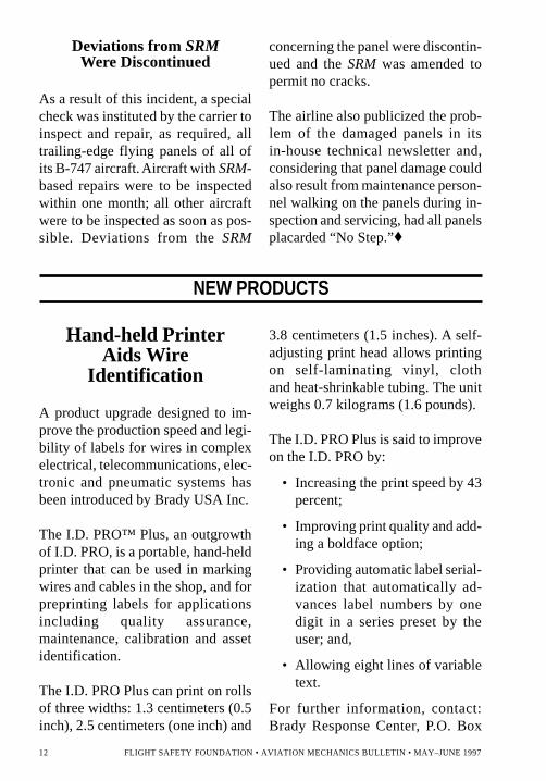
Presto Pneumatic Lift Tables use shopair rather than hydraulic cylinders, mo-tors, pumps, fluids and seals to pro-vide vertical travel and tilt of the tabletop. Capacities of the tables range from454 kilograms to 3,629 kilograms(1,000 pounds to 8,000 pounds), andtables can be equipped with hand, footor pedestal controls. The compressed-air lifting system employed is the Fir-estone Airstroke Actuator.™
The manufacturer of the tables, LeeEngineering Co., states that the ab-sence of hard wiring makes the tablerelatively easy to install. Use of shopair eliminates the need for hydraulicmaintenance.
For further information, contact:Dianna Cole at Lee Engineering Co.Inc., 505 Narragansett Park Drive,Pawtucket, RI 02861 U.S. Telephone:(401) 725-6100; Fax: (401) 728-7840.
LEDs GetOut of the Red
For a long time, red was the only day-light-visible color available in light-emitting diodes (LEDs). Because ofrecent advances in technology, LEDsare now available in virtually all col-ors of the spectrum — according toLedtronics Inc., manufacturer of LEDs— and are ideal replacements for con-ventional filament bulbs in many uses.Maintenance shop applications mightinclude status-indicator lights, controlpanels, signs, emergency annunciatorsand displays.
LEDs have several advantages overconventional bulbs. They last much
Presto Pneumatic Lift Table
14 FLIGHT SAFETY FOUNDATION • AVIATION MECHANICS BULLETIN • MAY–JUNE 1997
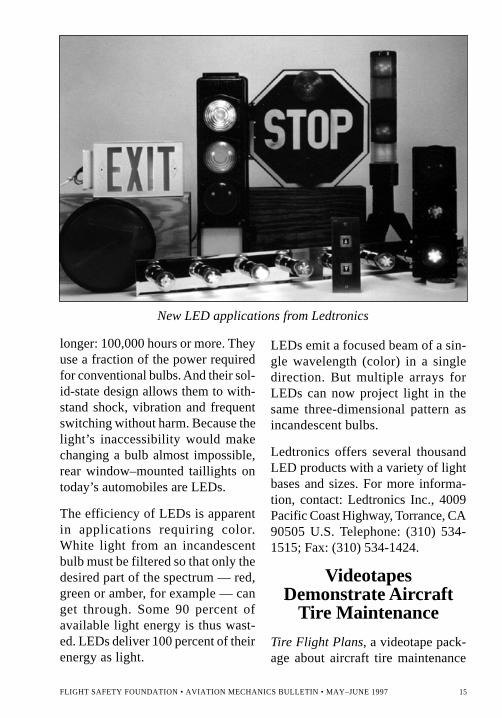
longer: 100,000 hours or more. Theyuse a fraction of the power requiredfor conventional bulbs. And their sol-id-state design allows them to with-stand shock, vibration and frequentswitching without harm. Because thelight’s inaccessibility would makechanging a bulb almost impossible,rear window–mounted taillights ontoday’s automobiles are LEDs.
The efficiency of LEDs is apparentin applications requiring color.White light from an incandescentbulb must be filtered so that only thedesired part of the spectrum — red,green or amber, for example — canget through. Some 90 percent ofavailable light energy is thus wast-ed. LEDs deliver 100 percent of theirenergy as light.
New LED applications from Ledtronics
LEDs emit a focused beam of a sin-gle wavelength (color) in a singledirection. But multiple arrays forLEDs can now project light in thesame three-dimensional pattern asincandescent bulbs.
Ledtronics offers several thousandLED products with a variety of lightbases and sizes. For more informa-tion, contact: Ledtronics Inc., 4009Pacific Coast Highway, Torrance, CA90505 U.S. Telephone: (310) 534-1515; Fax: (310) 534-1424.
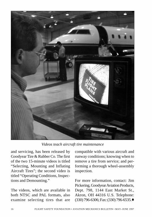
VideotapesDemonstrate Aircraft
Tire Maintenance
Tire Flight Plans, a videotape pack-age about aircraft tire maintenance
FLIGHT SAFETY FOUNDATION • AVIATION MECHANICS BULLETIN • MAY–JUNE 1997 15
Videos teach aircraft tire maintenance
and servicing, has been released byGoodyear Tire & Rubber Co. The firstof the two 15-minute videos is titled“Selecting, Mounting and InflatingAircraft Tires”; the second video istitled “Operating Conditions, Inspec-tions and Demounting.”
The videos, which are available inboth NTSC and PAL formats, alsoexamine selecting tires that are
compatible with various aircraft andrunway conditions; knowing when toremove a tire from service; and per-forming a thorough wheel-assemblyinspection.
For more information, contact: JimPickering, Goodyear Aviation Products,Dept. 798, 1144 East Market St.,Akron, OH 44316 U.S. Telephone:(330) 796-6306; Fax: (330) 796-6535.♦
16 FLIGHT SAFETY FOUNDATION • AVIATION MECHANICS BULLETIN • MAY–JUNE 1997

BLANKINSIDEBACK
COVER
A Joint Meeting of
Visit our World Wide Web site at http://www.flightsafety.org
Flight Safety FoundationInternational Federation
of Airworthiness27th International Conference
International Air Transport Association
iass50th annual
International Air Safety Seminar
W A S H I N G T O N , D . C .N o v e m b e r 3 – 6 , 1 9 9 7
For information contact:Steve Jones, director of membership, Flight Safety Foundation601 Madison Street, Suite 300, Alexandria, VA 22314 U.S.
Telephone: (703) 739-6700 Fax: (703) 739-6708
AVIATIONSAFETY:
CONFRONTINGTHE FUTURE