TECNAM P2010 - Aircraft Flight Manual - Breda Aviation
480
Page 0 - 1 Aircraft Flight Manual Doc. No. 2010/100 Edition 2 nd – 2015, October 30 th TECNAM P2010 MANUFACTURER: COSTRUZIONI AERONAUTICHE TECNAM S.r.l. AIRCRAFT MODEL: P2010 EASA TYPE CERTIFICATE NO: EASA.A.576 (DATED 2014, SEPTEMBER 26 TH ) SERIAL NUMBER: …………….............. BUILD YEAR: ……….………................ REGISTRATION MARKINGS: …………….…….. This manual is approved in accordance with 14 CFR 21.29 for US registered air- craft, and is approved by the Federal Aviation Administration. This Manual must be carried in the airplane at all times. The airplane has to be operated in compliance with procedures and limitations contained herein. Costruzioni Aeronautiche TECNAM srl Via Maiorise CAPUA (CE) – Italy Tel. +39 0823 99.75.38 WEB: www.tecnam.com
-
Upload
khangminh22 -
Category
Documents
-
view
0 -
download
0
Transcript of TECNAM P2010 - Aircraft Flight Manual - Breda Aviation

Page 0 - 1
Aircraft Flight Manual
Doc. No. 2010/100 Edition 2nd – 2015, October 30th
TECNAM P2010
MANUFACTURER: COSTRUZIONI AERONAUTICHE TECNAM S.r.l. AIRCRAFT MODEL: P2010 EASA TYPE CERTIFICATE NO: EASA.A.576 (DATED 2014, SEPTEMBER 26TH) SERIAL NUMBER: ……………..............
BUILD YEAR: ……….………................
REGISTRATION MARKINGS: …………….……..
This manual is approved in accordance with 14 CFR 21.29 for US registered air-craft, and is approved by the Federal Aviation Administration. This Manual must be carried in the airplane at all times. The airplane has to be operated in compliance with procedures and limitations contained herein. Costruzioni Aeronautiche TECNAM srl Via Maiorise CAPUA (CE) – Italy Tel. +39 0823 99.75.38 WEB: www.tecnam.com

Page 0 - 2
2nd Edition – Rev. 0
Aircraft Flight Manual
INDEX
INDEX
1. RECORD OF REVISIONS ............................................................... 3
2. LIST OF EFFECTIVE PAGES .......................................................... 7
3. FOREWORD ................................................................................... 8
4. SECTIONS LIST ............................................................................ 9
Page 0 - 3
2nd Edition, Rev. 0
Aircraft Flight Manual
RECORD OF REVISIONS
1. RECORD OF REVISIONS
Any revision to the present Manual, except actual weighing data, is recorded: a Record of Revisions is provided at the front of this manual and the operator is ad-vised to make sure that the record is kept up-to-date. The Manual issue is identified by Edition and Revision codes reported on each page, lower right side. The revision code is numerical and consists of the number "0"; subsequent revi-sions are identified by the change of the code from "0" to "1" for the first revision to the basic publication, "2" for the second one, etc. Should be necessary to completely reissue a publication for contents and format changes, the Edition code will change to the next number (“2” for the second edi-tion, “3” for the third edition etc). Additions, deletions and revisions to existing text will be identified by a revision bar (black line) in the left-hand margin of the page, adjacent to the change. When technical changes cause expansion or deletion of text which results in un-changed text appearing on a different page, a revision bar will be placed in the right-hand margin adjacent to the page number of all affected pages providing no other revision bar appears on the page. These pages will be updated to the current regular revision date. NOTE: It is the responsibility of the owner to maintain this handbook in a current status when it is being used for operational purposes.

Page 0 - 4
2nd Edition, Rev. 0
Aircraft Flight Manual
RECORD OF REVISIONS
Rev Revised page
Description of Revision
Tecnam Approval EASA Approval Or Under DOA
Privileges DO OoA HDO
0 – First issue D.Ronca C.Caruso M. Oliva New Edition

Page 0 - 5
2nd Edition, Rev. 0
Aircraft Flight Manual
RECORD OF REVISIONS
Rev Revised page
Description of Revision
Tecnam Approval EASA Approval Or Under DOA
Privileges DO OoA HDO

Page 0 - 6
2nd Edition, Rev. 0
Aircraft Flight Manual
INTENTIONALLY LEFT BLANK

Page 0 - 7
Aircraft Flight Manual
LIST OF EFFECTIVE PAGES
2nd Edition, Rev. 0
2. LIST OF EFFECTIVE PAGES
The List of Effective Pages (LOEP), applicable to manuals of every operator, lists all the basic AFM pages: each manual could contain either basic pages or one variant of these pages when the pages of some Supplements are embodied. Pages affected by the current revision are indicated by an asterisk (*) following the re-vision code. Should supplements be embodied in accordance with approved instructions, make refer-ence to the LOEP addressed on Supplements themselves.
1st Edition, Rev 0 ..................... September 26, 2014 1st Edition, Rev 1 ..................... April 8, 2015 2nd Edition, Rev0 ..................... October 30, 2015
Section Pages Revision Section 0 Pages 1 thru 10 Rev 0 Section 1 Pages 1 thru 16 Rev 0 Section 2 Pages 1 thru 16 Rev 0 Section 3 Pages 1 thru 30 Rev 0 Section 4 Pages 1 thru 26 Rev 0 Section 5 Pages 1 thru 18 Rev 0 Section 6 Pages 1 thru 12 Rev 0 Section 7 Pages 1 thru 38 Rev 0 Section 8 Pages 1 thru 16 Rev 0
Supplement List Section 9 Pages 1 thru 4 Rev 0 Supplements LOEP: make reference to the Supplements Cover Pages

Page 0 - 8
Aircraft Flight Manual
FOREWORD
2nd Edition, Rev. 0
3. FOREWORD
Section 1 supplies general information and it contains definitions, symbols explana-tions, acronyms and terminology used. Before using the airplane, you are recommended to read carefully this manual: a deep knowledge of airplane features and limitations will allow you for operating the airplane safely. For further information, please contact:
COSTRUZIONI AERONAUTICHE TECNAM s.r.l.
Via MAIORISE
CAPUA (CE) - ITALY
+39 0823.99.75.38
www.tecnam.com

Page 0 - 9
2nd Edition, Rev. 0
Aircraft Flight Manual
SECTIONS LIST
4. SECTIONS LIST
General (*) Section 1
Limitations (**) Section 2
Emergency Procedures (*) Section 3
Normal Procedures (*) Section 4
Performances (*) Section 5
Weight and Balance (*) Section 6
Airframe and Systems description (*) Section 7
Airplane Care and Maintenance (*) Section 8
Supplements (***) Section 9
(*) non-approved Section (**) approved Section (***) partially approved Section - approved parts, if any, are reported in the supplements.

Page 0 - 10
2nd Edition, Rev. 0
Aircraft Flight Manual
INTENTIONALLY LEFT BLANK

Page 1 - 1
Section 1 – General
INDEX
2nd Edition, Rev.0
SECTION 1 - GENERAL
INDEX
1. INTRODUCTION ............................................................................ 3
2. CERTIFICATION BASIS ................................................................. 3
3. WARNING – CAUTION – NOTE ...................................................... 3
4. THREE-VIEW AND DIMENSIONS ................................................... 4
5. ENGINE ......................................................................................... 6
6. PROPELLER ................................................................................... 6
7. FLIGHT CONTROL SURFACES TRAVEL ........................................ 7
8. SPECIFIC LOADINGS .................................................................... 7
9. ACRONYMS AND TERMINOLOGY ................................................. 9
10. UNIT CONVERSION CHART ........................................................ 14
11. LITRES / US GALLONS CONVERSION CHART ............................ 15

Page 1 - 2
Section 1 – General
2nd Edition, Rev.0
INTENTIONALLY LEFT BLANK

Page 1 - 3
Section 1 – General
INTRODUCTION
2nd Edition, Rev.0
1. INTRODUCTION
The Aircraft Flight Manual has been prepared to provide pilots and instructors with information for the safe and efficient operation of this aeroplane.
This manual also contains supplemental data supplied by the aeroplane manufac-turer.
2. CERTIFICATION BASIS
This type of aircraft has been approved by the European Aviation Safety Agency in accordance with CS-23 including Amendment 2 and the Type Certificate No. EASA.A.576 has been issued on 26th September 2014.
Category of Airworthiness: Normal.
Noise Certification Basis: EASA CS 36 Amendment 2.
This type of aircraft has been validated also in the normal category of 14 CFR part 23 and part 36
3. WARNING – CAUTION – NOTE
Following definitions apply to warnings, cautions and notes used in the Aircraft Flight Manual.
WARNING
means that the non-observation of the corresponding procedure leads to an immediate or important degradation of the flight safety.
CAUTION
means that the non-observation of the corresponding procedure leads to a minor or to a more or less long term degradation of the flight safety
Draws the attention to any special item not directly related to safety but which is important or unusual.
.
NOTE

Page 1 - 4
Section 1 – General
THREE-VIEW AND DIMENSIONS
2nd Edition, Rev.0
4. THREE-VIEW AND DIMENSIONS
Figure 1 – General views

Page 1 - 5
Section 1 – General
THREE-VIEW AND DIMENSIONS
2nd Edition, Rev.0
Dimensions
Overall dimensions
Wing Span …..…………………………….. 10.30 m / 33.79 ft
Overall Length ……………………………. 7.97 m / 26.15 ft
Overall height ……………………………... 2.64 m / 8.66 ft
Stabilator Span ……………………………. 3.35 m / 10.99 ft
Wing
Wing surface ..…………………………….. 13.9 m2 / 149.6 ft2
Mean Geometric Chord ...………………… 1.349 m / 4.427 ft
Dihedral …………………………………... 1°
Aspect ratio ………………………………. 7.63
Fuselage
Cabin width ..…………………………….. 1.14 m / 3.74 ft
Cabin length..…………………………….. 2.3 m / 7.54 ft
Landing Gear
Wheels Track …………………………….. 2.1 m / 6.89 ft
Wheels base ……………………………… 2.15 m / 7.05 ft
Main Gear Tire …………………………… 6.00-6
Nose Gear Tire …………………………… 5.00-5

Page 1 - 6
Section 1 – General
GENERAL FEATURES
2nd Edition, Rev.0
TERMINOLOGYFLI
GHT CONTROL
SURFACES
TRAVEL
5. ENGINE
Manufacturer …………………………… Lycoming Engines
Model …………………………………... IO-360-M1A
Type Certificate ………………………... EASA TCDS no. IM.E.032
Engine type …………………………….. Fuel injected (IO), direct drive, four cylinder horizontally opposed, air cooled with down exhaust outlets.
Maximum power …….
Maximum continuous power …………...
134.0 kW (180 hp) @ 2700 rpm
134.0 kW (180 hp) @ 2700 rpm
6. PROPELLER
Manufacturer ………………………….. MT Propeller
Model …………………………………. MT 188 R 145 – 4G
Type Certificate ……………………….. EASA TCDS no. P.006
Blades/hub …………………………….. 2 wood/composite blades – aluminium hub
Diameter ………………………………. 1880 mm (74 in) (no reduction allowed)
Type …………………………………… Fixed pitch

Page 1 - 7
Section 1 – General
GENERAL FEATURES
2nd Edition, Rev.0
TERMINOLOGYSP
ECIFIC LOADINGS
7. FLIGHT CONTROL SURFACES TRAVEL
Ailerons Up 19°; Down 14 ° ( 2°)
Stabilator* Up 6°; Down 17° ( 2°)
Stabilator trim tab Up 3°; Down 15° ( 1°)
Rudder RH 25°; LH 25° ( 2°)
Rudder trim tab RH 20°; LH 20° ( 2°)
Flaps 0°; 20°; 40° ( 1°)
*degrees are measured from the Stabilator Leading Edge.
8. SPECIFIC LOADINGS
MTOW 1160 kg (2557 lb)
Wing Loading 83.45 kg/m2 (17.09 lb/ft2)
Power Loading 6.44 kg/hp (14.21 lb/hp)

Page 1 - 8
Section 1 – General
2nd Edition, Rev.0
TERMINOLOGYSP
ECIFIC LOADINGS
INTENTIONALLY LEFT BLANK

Page 1 - 9
Section 1 – General
ACRONYMS AND TERMINOLOGY
2nd Edition, Rev.0
9. ACRONYMS AND TERMINOLOGY
KCAS Calibrated Airspeed is the indicated airspeed expressed in knots, corrected taking into account the errors related to the instrument itself and its installation.
KIAS Indicated Airspeed is the speed shown on the airspeed indicator and it is expressed in knots.
KTAS True Airspeed is the KCAS airspeed corrected taking into ac-count altitude and temperature.
VA Design Manoeuvring speed is the speed above the which it is not allowed to make full or abrupt control movement.
VFE Maximum Flap Extended speed is the highest speed permissible with flaps extended.
VNO Maximum Structural Cruising Speed is the speed that should not be exceeded, except in smooth air and only with caution.
VNE Never Exceed Speed is the speed limit that may not be exceeded at any time.
VO Operating Manoeuvring speed is the speed above the which it is not allowed to make full or abrupt control movement
VS Stall Speed.
VS0 Stall Speed in landing configuration (flaps and landing gear ex-tended).
VS1 Stall speed in clean configuration (flaps 0°).
VX Best Angle-of-Climb Speed is the speed which results in the greatest gain of altitude with respect to a given horizontal dis-tance.
VY Best Rate-of-Climb Speed is the speed which results in the great-est gain in altitude in a given time.
VR Rotation speed: is the speed at which the aircraft rotates about the pitch axis during takeoff
VLOF Lift off speed: is the speed at which the aircraft generally lifts off from the ground.
Vobs Obstacle speed: is the speed at which the aircraft flies over a 15m obstacle during takeoff or landing.

Page 1 - 10
Section 1 – General
ACRONYMS AND TERMINOLOGY
2nd Edition, Rev.0
Meteorological terminology
ISA International Standard Atmosphere: is the air atmospheric standard condition at sea level, at 15 °C (59 °F) and at 1013.25 hPa (29.92 inHg).
QFE Official atmospheric pressure at airport level: it indicates the air-craft absolute altitude with respect to the official airport level.
QNH Theoretical atmospheric pressure at sea level: is the atmospheric pressure reported at the medium sea level, through the standard air pressure-altitude relationship, starting from the airport QFE.
OAT Outside Air Temperature is the air static temperature expressed in degrees Celsius (°C).
TS Standard Temperature is 15 °C at sea level pressure altitude and decreased by 2 °C for each 1000 ft of altitude.
HP Pressure Altitude is the altitude read from an altimeter when the barometric subscale has been set to 1013 mb.

Page 1 - 11
Section 1 – General
ACRONYMS AND TERMINOLOGY
2nd Edition, Rev.0
Aircraft performance and flight planning terminology
Crosswind Velocity is the velocity of the crosswind component for the which adequate control of the air-plane during takeoff and landing is assured.
Usable fuel is the fuel available for flight planning.
Unusable fuel is the quantity of fuel that cannot be safely used in flight.
G is the acceleration of gravity. TOR is the takeoff distance measured from actual
start to MLG wheel liftoff point. TOD is total takeoff distance measured from start
to 15m obstacle clearing.
GR is the distance measured during landing from actual touchdown to stop point.
LD is the distance measured during landing, from 15m obstacle clearing to actual stop.
S/R is the specific range, that is the distance (in nautical miles) which can be expected at a specific power setting and/or flight configu-ration per kilo of fuel used.

Page 1 - 12
Section 1 – General
ACRONYMS AND TERMINOLOGY
2nd Edition, Rev.0
Weight and balance terminology
Datum “Reference datum” is an imaginary vertical plane from which all horizontal distances are measured for balance purposes.
Arm is the horizontal distance of an item meas-ured from the reference datum.
Moment is the product of the weight of an item mul-tiplied by its arm.
C.G. Center of Gravity is the point at which the airplane, or equipment, would balance if suspended. Its distance from the reference datum is found by dividing the total moment by the total weight of the aircraft.
Standard Empty Weight is the weight of the aircraft with engine flu-ids and oil at operating levels.
Basic Empty Weight is the standard empty weight to which it is added the optional equipment weight.
Useful Load is the difference between maximum takeoff weight and the basic empty weight.
Maximum Takeoff Weight is the maximum weight approved to perform the takeoff.
Maximum Landing Weight is the maximum weight approved for the landing touchdown (for P2010 it is equiva-lent to the Maximum Takeoff Weight).

Page 1 - 13
Section 1 – General
2nd Edition, Rev.0
INTENTIONALLY LEFT BLANK

Page 1 - 14
Section 1 – General
UNIT CONVERSION CHART
2nd Edition, Rev.0
10. UNIT CONVERSION CHART
MOLTIPLYING BY YIELDS
TEMPERATURE Fahrenheit [°F]
59
32 F Celsius [°C]
Celsius [°C] 95
32
C Fahrenheit [°F]
FORCES Kilograms [kg] 2.205 Pounds [lbs]
Pounds [lbs] 0.4536 Kilograms [kg]
SPEED Meters per second [m/s] 196.86 Feet per minute [ft/min]
Feet per minute [ft/min] 0.00508 Meters per se-cond
[m/s]
Knots [kts] 1.853 Kilometres / hour [km/h]
Kilometres / hour [km/h] 0.5396 Knots [kts]
PRESSURE Atmosphere [atm] 14.7 Pounds / sq. in [psi]
Pounds / sq. in [psi] 0.068 Atmosphere [atm]
LENGTH Kilometres [km] 0.5396 Nautical miles [nm]
Nautical miles [nm] 1.853 Kilometres [km]
Meters [m] 3.281 Feet [ft]
Feet [ft] 0.3048 Meters [m]
Centimetres [cm] 0.3937 Inches [in]
Inches [in] 2.540 Centimetres [cm]
VOLUME Litres [l] 0.2642 U.S. Gallons [US Gal]
U.S. Gallons [US Gal] 3.785 Litres [l]
AREA Square meters [m2] 10.76 Square feet [sq ft]
Square feet [sq ft] 0.0929 Square meters [m2]

Page 1 - 15
Section 1 – General
LITRES / US GALLONS CONVERSION CHART
2nd Edition, Rev.0
11. LITRES / US GALLONS CONVERSION CHART
Litres US Gallons US Gallons Litres
5 1.3 1 3.8
10 2.6 2 7.6
15 4.0 3 11.4
20 5.3 4 15.1
25 6.6 6 22.7
30 7.9 8 30.3
35 9.2 10 37.9
40 10.6 12 45.4
45 11.9 14 53.0
50 13.2 16 60.6
60 15.9 18 68.1
70 18.5 20 75.7
80 21.1 22 83.3
90 23.8 24 90.9
100 26.4 26 98.4
110 29.1 28 106.0
120 31.7 30 113.6
130 34.3 32 121.1
140 37.7 34 128.7
150 39.6 36 136.3
160 42.3 38 143.8
170 44.9 40 151.4
180 47.6 42 159
190 50.2 45 170.3
200 52.8
47 177.9
210 55.5 50 189.3
220 58.1 55 208.2
230 60.7 60 227.1
240 63.4 63 238.4

Page 1 - 16
Section 1 – General
2nd Edition, Rev.0
INTENTIONALLY LEFT BLANK
Section 2 – Limitations
INDEX
Page 2 - 1
2nd Edition, Rev.0
SECTION 2 – LIMITATIONS
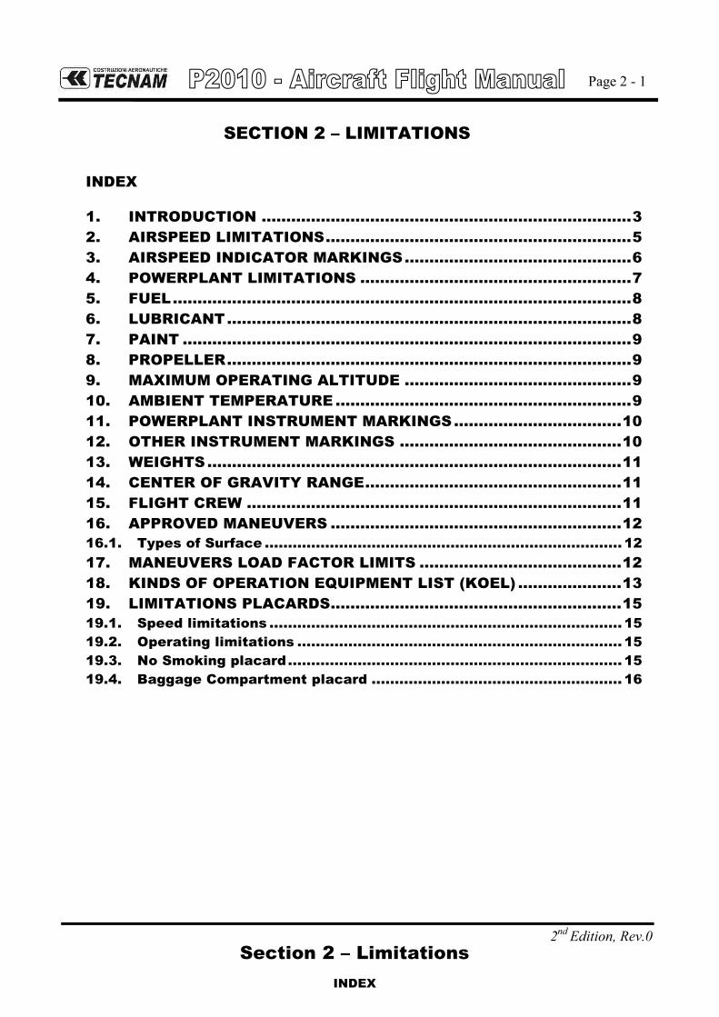
INDEX
1. INTRODUCTION ........................................................................... 3
2. AIRSPEED LIMITATIONS .............................................................. 5
3. AIRSPEED INDICATOR MARKINGS .............................................. 6
4. POWERPLANT LIMITATIONS ....................................................... 7
5. FUEL ............................................................................................. 8
6. LUBRICANT .................................................................................. 8
7. PAINT ........................................................................................... 9
8. PROPELLER .................................................................................. 9
9. MAXIMUM OPERATING ALTITUDE .............................................. 9
10. AMBIENT TEMPERATURE ............................................................ 9
11. POWERPLANT INSTRUMENT MARKINGS .................................. 10
12. OTHER INSTRUMENT MARKINGS ............................................. 10
13. WEIGHTS .................................................................................... 11
14. CENTER OF GRAVITY RANGE .................................................... 11
15. FLIGHT CREW ............................................................................ 11
16. APPROVED MANEUVERS ........................................................... 12
16.1. Types of Surface ............................................................................. 12
17. MANEUVERS LOAD FACTOR LIMITS ......................................... 12
18. KINDS OF OPERATION EQUIPMENT LIST (KOEL) ..................... 13
19. LIMITATIONS PLACARDS........................................................... 15
19.1. Speed limitations ............................................................................ 15
19.2. Operating limitations ...................................................................... 15
19.3. No Smoking placard ........................................................................ 15
19.4. Baggage Compartment placard ...................................................... 16

Page 2 - 2
Section 2 – Limitations
2nd Edition, Rev.0
INTENTIONALLY LEFT BLANK

Page 2 - 3
2nd Edition, Rev.0
Section 2 – Limitations
INTRODUCTION
1. INTRODUCTION
Section 2 includes operating limitations, instrument markings and basic placards necessary for safe operation of the aeroplane, its engine and standard systems and equipment.

Page 2 - 4
2nd Edition, Rev.0
Section 2 – Limitations
INTENTIONALLY LEFT BLANK

Page 2 - 5
2nd Edition, Rev.0
Section 2 – Limitations
AIRSPEED LIMITATIONS
2. AIRSPEED LIMITATIONS
The following table addresses the airspeed limitations and their operational signifi-cance:
AIRSPEED KIAS KCAS REMARKS
VNE Never exceed speed 166 164 Do not exceed this speed in
any operation.
VNO Maximum Structural Cruising Speed
132 130 Do not exceed this speed except in smooth air, and only with caution.
VA
Design Manoeuvring speed 120 119 Do not make full or abrupt control movement above this speed, because under certain conditions the air-craft may be overstressed by full control movement.
VO
Operating Manoeuvring speed
VFE Maximum flaps extended speed 91 92 Do not exceed this speed for indicated flaps setting.

Page 2 - 6
Section 2 – Limitations
AIRSPEED INDICATOR MARKINGS
2nd Edition, Rev.0
3. AIRSPEED INDICATOR MARKINGS
Airspeed indicator markings and their colour code are explained in the following table.
MARKING KIAS EXPLANATION
White arc 50 – 91 Positive Flap Operating Range (lower limit is VSO, at specified maximum weight and upper limit is the maximum speed permissi-ble with landing flaps extension).
Green arc 59– 132 Normal Operating Range (lower limit is VS1 at specified maximum weight and most for-ward c.g. with flaps retracted and upper limit is maximum structural speed VNO).
Yellow arc 132 – 166 Manoeuvres must be conducted with caution and only in smooth air.
Red line 166 Maximum speed for all operations.

Page 2 - 7
Section 2 – Limitations
POWERPLANT LIMITATIONS
2nd Edition, Rev.0
4. POWERPLANT LIMITATIONS
Following table reports the operating limitations the installed engine:
ENGINE MANUFACTURER: Lycoming Engines
ENGINE MODEL: IO-360-M1A
MAXIMUM POWER:
Max Power (hp)
Max rpm.
Prop. rpm
Max. T.O. 180 2700
Max. Cont. 180 2700
Temperatures:
Max CHT ……………………………………….. 500° F (260° C)
Max Oil …………………………………………. 245° F (118° C)
Oil Pressure:
Minimum Idling ………………………………… 25 psi (1.7 Bar)
Minimum Normal ………………………………. 55 psi (3.8 Bar)
Maximum Normal ……………………………… 95 psi (6.5 Bar)
Starting, Warm-up, taxi and take-off (Max) …… 115 psi (7.9 Bar)
Fuel pressure:
- At Inlet to fuel injector:
Minimum .............................................................. 14 psi (0.96 Bar)
Maximum ............................................................. 35 psi (2.41 Bar)

Page 2 - 8
Section 2 – Limitations
FUEL & LUBRIFICANT
2nd Edition, Rev.0
5. FUEL
2 TANKS: 120 litres each one (31.7 US gallons)
MAXIMUM CAPACITY: 240 litres (63.4 US gallons)
MAXIMUM USABLE FUEL: 231 litres (61 US gallons)
APPROVED FUEL: AVGAS Grade 91/96 or 100 LL (ASTM D910)
For additional information, refer to Lycoming Service Instruction No. 1070, latest issue.
6. LUBRICANT
Recommended Grade Oil:
Average Ambient Temperature
All Temperatures
Above 80°F
Above 60°F
30°F to 90°F
0°F to 70°F
Below 10°F
MIL-L-6082B or
SAEJ1966 Spec.
Mineral Grades
----
SAE60
SAE50
SAE40
SAE30
SAE20
MIL-L-22851 or
SAEJ1899 Spec.
Ashless Dispersant Grades
SAE15W50 or SAE20W-50
SAE60
SAE40 or SAE50
SAE40
SAE40, SAE30, SAE20W40
SAE30 or SAE20W30
For additional info, refer to “(L)IO-360-M1A Operation and Installation Manual”, latest issue, “Operating instruction” Section.

Page 2 - 9
2nd Edition, Rev.0
Section 2 – Limitations
PAINT, PROPELLER, MAX ALTITUDE AND OAT
7. PAINT
To ensure that the temperature of the composite structure does not exceed limits, the outer surface of the aeroplane must be painted with white paint, except for areas of registration marks, placards, and ornament.
Refer to Aircraft Maintenance Manual (AMM), ATA Chapter 4 and 51, for specific paint requirements.
8. PROPELLER
MANUFACTURER: .…….. MT Propeller
MODEL: …………….……. MT 188 R 145 – 4G
TYPE: .……………….…… wood/composite 2-blade, fixed pitch
DIAMETER: ……………... 1880 mm (74 in) (no reduction is permitted)
9. MAXIMUM OPERATING ALTITUDE
Maximum operating altitude is 12000 ft (3658 m) MSL.
CAUTION
At altitudes above 10000 ft (3048 m) up to and including 12000 ft (3658 m), flight crew is recommended to use supplemental oxygen.
10. AMBIENT TEMPERATURE
Ambient temperature: from -25 °C (-13 °F) to +50 °C (122 °F).
WARNING
Flight in expected and/or known icing conditions is forbidden.

Page 2 - 10
2nd Edition, Rev.0
Section 2 – Limitations
POWERPLANT AND OTHER INSTRUMENT MARKINGS
11. POWERPLANT INSTRUMENT MARKINGS
Powerplant instrument markings and their colour code significance are shown below:
INSTRUMENT
RED ARC
Minimum limit
WHITE ARC
Advisory
GREEN ARC
Safe operation
YELLOW ARC
Caution
RED ARC
Maximum limit
PROPELLER RPM / / 950-2700 0-950 2700-2800
OIL TEMP. °F / / 140-245 0 - 140 245 - 255
CHT °F / 435 (line) 150-475 0 – 150
475-500 500-510
EGT °F / 1000-1500 / 1375 (line) 1500-1550
OIL PRESS psi 0-25 / 55-95 25 - 55
95-115 115 - 125
FUEL PRESS psi 0-14 / 14-35 / 35 - 40
FUEL QTY litres 0
/ 0-115
/ / gal 0 0-30,4
FUEL FLOW l/hr
/ 0-75
/ / / gal/hr 0-20
12. OTHER INSTRUMENT MARKINGS
INSTRUMENT RED ARC
Minimum limit
GREEN ARC
Safe operation
YELLOW ARC
Caution
RED ARC
Maximum limit
Voltmeter 20-21 Volt 24–30 Volt 21–24 Volt 30-31 Volt

Page 2 - 11
Section 2 – Limitations
WEIGHTS
2nd Edition, Rev.0
13. WEIGHTS
Refer to Section 6 for proper aircraft and baggage loading.
14. CENTER OF GRAVITY RANGE
Datum Vertical plane tangent to the wing leading edge (the aircraft must be levelled in the longitudinal plane)
Levelling Refer to the seat track supporting beams (see procedure in Section 6)
Forward limit 0.262 m (10.3 in) (19% MAC) aft of datum for all weights
Aft limit 0.440 m (17.3 in) (32% MAC) aft of datum for all weights
WARNING
The pilot is responsible for ensuring that the airplane is properly loaded. Refer to Section 6 for appropriate instruc-tions.
15. FLIGHT CREW
Minimum crew: 1 pilot Maximum seating configuration: 4 people (including the pilot)
Condition Weight
Maximum takeoff weight 1160 kg 2557 lb
Maximum landing weight 1160 kg 2557 lb
Maximum baggage weight 40 kg 88 lb
Baggage Compartment Weight
Maximum weight 40 kg 88 lb
Maximum specific pressure 0.72 kg/dm2 14.9 lb/ft2
NOTE

Page 2 - 12
Section 2 – Limitations
MANEUVERS
2nd Edition, Rev.0
16. APPROVED MANEUVERS
The aircraft is certified in Normal Category in accordance with EASA CS-23and FAA 14 CFR part 23 regulations. Non aerobatic operations include: Any manoeuvre pertaining to “normal” flight
Stalls (except whip stalls)
Lazy eights
Turns in which the angle of bank is not more than 60°
Chandelle
WARNING
Acrobatic manoeuvres, including spins and turns with angle of bank of more than 60°, are not approved for such a category.
In addition Intentional shutdown of engine in flight is forbidden.
WARNING
Limit load factor could be exceeded by moving flight controls to maxi-mum deflection at a speed above VA=VO (120 KIAS, Manoeuvring Speed).
WARNING
Flight in expected and/or known icing conditions, in proximity of storms or in severe turbulence is forbidden.
16.1. TYPES OF SURFACE
This aircraft may operate on both paved and grass surfaces, refer to Section 5 for impacts on performances.
17. MANEUVERS LOAD FACTOR LIMITS
Maneuver load factors limits are as follows: Positive Negative
+ 3.8 g - 1.52 g Maneuver load factors limits with flaps extended are as follows:
Positive
+ 2 g
Negative
0 g

Page 2 - 13
Section 2 – Limitations
KOEL
2nd Edition, Rev.0
18. KINDS OF OPERATION EQUIPMENT LIST (KOEL)
This paragraph reports the KOEL table, concerning the equipment list required on board under CS-23 and Far-23 regulations to allow flight operations in VFR Day/Night and IFR Day/Night. Flight in VFR Day/Night and IFR is permitted only if the prescribed equipment is installed and operational. Additional equipment, or a different equipment list, for the intended operation may be required by national operational requirements and also depends on the airspace classification and route to be flown. The owner is responsible for fulfilling these requirements.
Equipment VFR Day VFR Night IFR Day IFR Night Note
External Power Circuit Breakers ● ● ● ● As Required Battery ● ● ● ● Safety Equipment & Furnishing First Aid kit ● ● ● ● Fire extinguisher ● ● ● ● ELT ● ● ● ● Torch (with spare batteries) ● ● Ice Protection Pitot heating system ● ● ● Landing Gear Wheel pants Removable Lights Landing/taxi lights ● ● ● ● Strobe lights ● ● ● ● NAV lights ● ● ● ● Cabin lights ● ● Instrument lights ● ● Emergency light ● ● Dimming Devices ● ● Day/Night switch ● ● COM/Navigation/Engine parameters Magnetic compass ● ● ● ● GARMIN G1000 Suite ● ● ● ● MD 302 suite ● ● ● Pitot system ● ● ● ● Clock ● ● ● ● Flight Controls Pitch trim indicator ● ● ● ● Flap System ● ● ● ● Flaps position lights ● ● ● ● Rudder trim system ● ● ● ● only for VFR operations,
rudder trim system may be inoperative provided the trim tab is fixed in the streamlined position and the system is electrically disabled
Stall warning system ● ● ● ● VFR Day VFR Night IFR Day IFR Night

Page 2 - 14
Section 2 – Limitations
2nd Edition, Rev.0
INTENTIONALLY LEFT BLANK

Page 2 - 15
Section 2 – Limitations
LIMITATIONS PLACARDS
2nd Edition, Rev.0
19. LIMITATIONS PLACARDS
Hereinafter limitation placards, related to the operating limitations, are placed in
plain view on the pilot.
19.1. SPEED LIMITATIONS
On the left side instrument panel, above on the left, it is placed the following plac-
ard reporting the speed limitations:
19.2. OPERATING LIMITATIONS
On the central side of the instrument panel, the following placard is placed remind-
ing the observance of aircraft operating limitations according to installed equipment
configuration, see KOEL paragraph 18.
19.3. NO SMOKING PLACARD
On the right hand side of the instrument panel the following placard is placed re-
minding the observance for “no smoking”:

Page 2 - 16
Section 2 – Limitations
LIMITATIONS PLACARDS
2nd Edition, Rev.0
19.4. BAGGAGE COMPARTMENT PLACARD
Behind the baggage compartment door the following placard is placed:

Page 3 - 1
Section 3 – Emergency procedures
INDEX
2nd Edition, Rev.0
SECTION 3 – EMERGENCY PROCEDURES
INDEX
1. Introduction ..................................................................................... 3
2. Failures indicated on the annunciation window ............................ 5
2.1. Alternator failure .......................................................................... 5
2.2. Pitot heating system failure ......................................................... 6
3. G1000 System Failures ................................................................... 7
3.1. Loss of information displayed ...................................................... 7
3.2. Loss of airspeed information ....................................................... 7
3.3. Loss of attitude information ........................................................ 8
3.4. Loss of altitude information ......................................................... 8
3.5. Loss of vertical speed information .............................................. 9
3.6. Loss of heading information ........................................................ 9
3.7. Display failure ............................................................................. 10
4. Engine securing ............................................................................. 11
5. Aircraft evacuation ........................................................................ 11
6. Engine failures ............................................................................... 13
6.1. Engine failure during takeoff run ............................................... 13
6.2. Engine failure after Take-off ...................................................... 13
6.3. Propeller overspeed ................................................................... 14
6.4. Irregular rpm ............................................................................... 14
6.5. CHT limit exceedance ................................................................ 15
6.6. Oil temperature limit exceedance ............................................. 15
6.7. Oil pressure limits exceedance ................................................. 16
Low oil pressure ......................................................................................................................................... 16 High oil pressure ........................................................................................................................................ 16
6.8. Low fuel pressure ....................................................................... 17
6.9. High fuel pressure ...................................................................... 17
6.10. Defective engine controls ....................................................... 18
7. Inflight engine restart ................................................................... 19
7.1. Propeller windmilling .................................................................. 19
8. Smoke and fire ............................................................................... 21
8.1. Engine fire on the ground ........................................................... 21

Page 3 - 2
Section 3 – Emergency procedures
INDEX
2nd Edition, Rev.0
8.2. Engine fire during takeoff .......................................................... 21
8.3. Engine fire in flight ..................................................................... 21
8.4. Electrical smoke in cabin on the ground .................................. 22
8.5. Electrical smoke in cabin during flight ..................................... 22
9. Recovery from unintentional spin ................................................. 23
10. Other emergencies ........................................................................ 25
10.1. Loss of Essential Bus .............................................................. 25
10.2. Loss of Main Bus ..................................................................... 25
10.3. Electrical system overall failure ............................................. 26
10.4. Static port failure .................................................................... 26
10.5. Unintentional flight into icing conditions ............................... 27
10.6. Flaps control failure ................................................................ 27
10.7. Electrical Rudder Trim control failure .................................... 28
11. Landing emergencies .................................................................... 29
11.1. Forced landing without engine power .................................... 29
11.2. Power-on forced landing ......................................................... 29
11.3. Landing with nose landing gear tire deflated ........................ 30
11.4. Landing with a main landing gear tire deflated ..................... 30

Page 3 - 3
Section 3 – Emergency procedures
INTRODUCTION
2nd Edition, Rev.0
1. INTRODUCTION
Section 3 includes checklists and detailed procedures for coping with various types of emergency conditions that could arise. Before operating the aircraft, the pilot should become thoroughly familiar with the present manual and, in particular, with the present Section. Further, a contin-ued and appropriate training should be provided. Two types of emergency procedures are hereby given:
a. “Bold faces” which must be known by heart and executed in the correct and com-plete sequence, as soon as possible as the failure is detected and recognized; These procedures characters are boxed and highlighted, as shown below:
BEFORE ROTATION: ABORT TAKE OFF
1. Throttle IDLE 2. Rudder Keep heading control 3. - - 4. - -
b. Other procedures which should be well theoretically know and mastered, but that are not time critical and can be executed entering and following step by step the AFM appropriate checklist.
In case of emergency the pilot should acts as follows: 1. Maintain aircraft control 2. Analyse the situation 3. Apply the pertinent procedure 4. Inform the Air Traffic Control if time and conditions permit
The following definitions apply:
Land as soon as possible: land without delay at the nearest suitable area at which a safe approach and landing is as-sured.
Land as soon as practical: land at the nearest approved landing area where suitable repairs can be made.
NOTE

Page 3 - 4
Section 3 – Emergency procedures
2nd Edition, Rev.0
INTENTIONALLY LEFT BLANK
Page 3 - 5
Section 3 – Emergency procedures
ALTERNATOR FAILURE
2nd Edition, Rev.0
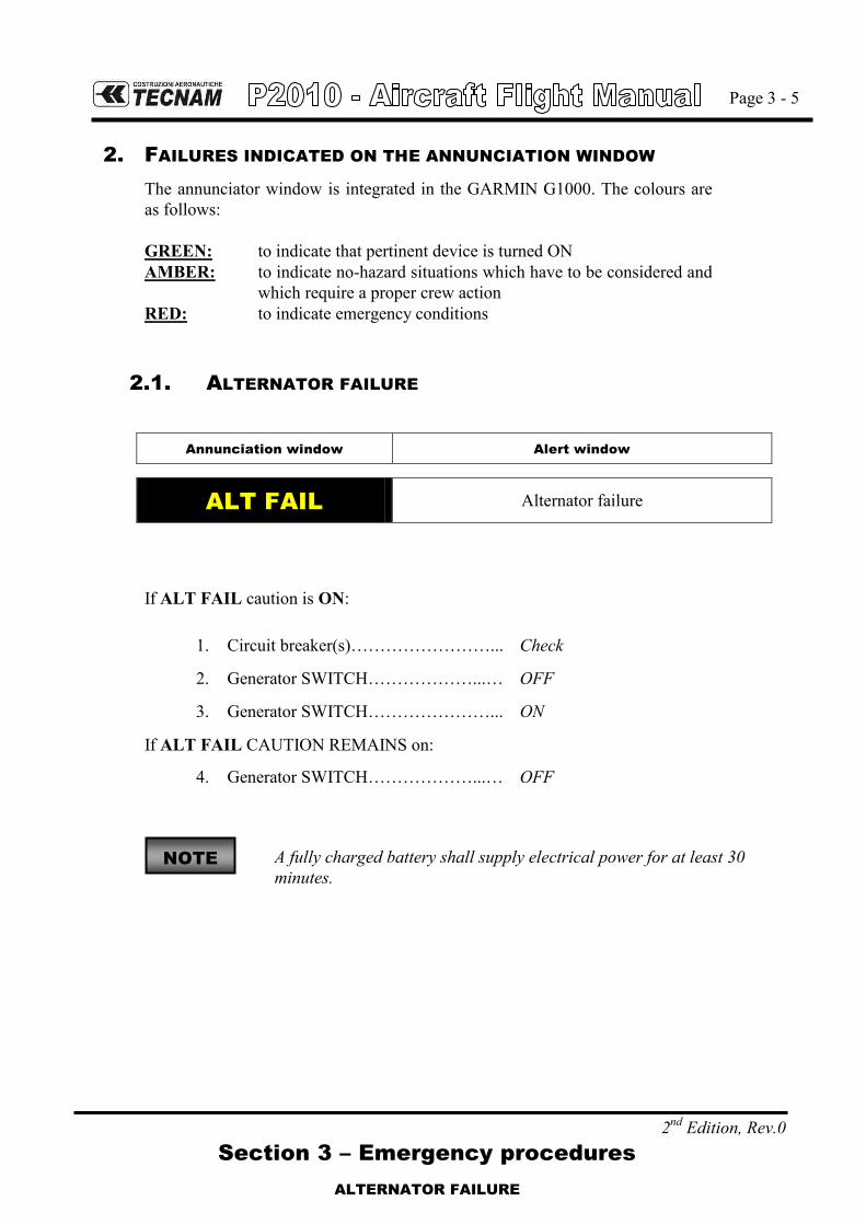
2. FAILURES INDICATED ON THE ANNUNCIATION WINDOW
The annunciator window is integrated in the GARMIN G1000. The colours are as follows: GREEN: to indicate that pertinent device is turned ON AMBER: to indicate no-hazard situations which have to be considered and
which require a proper crew action RED: to indicate emergency conditions
2.1. ALTERNATOR FAILURE
Annunciation window Alert window
ALT FAIL Alternator failure
If ALT FAIL caution is ON:
1. Circuit breaker(s)……………………... Check
2. Generator SWITCH………………...… OFF
3. Generator SWITCH…………………... ON
If ALT FAIL CAUTION REMAINS on:
4. Generator SWITCH………………...… OFF
A fully charged battery shall supply electrical power for at least 30 minutes.
NOTE

Page 3 - 6
Section 3 – Emergency procedures
PITOT HEATING SYSTEM FAILURE
2nd Edition, Rev.0
2.2. PITOT HEATING SYSTEM FAILURE
Annunciation window Alert window
PITOT HEAT ON Pitot heat on
PITOT HEAT Pitot heat
When the Pitot Heating system is activated, the green PITOT HEAT ON advi-sory light turns on and the amber PITOT HEAT caution light turns OFF, indi-cating that the Pitot Heating system is functioning properly. If the amber PITOT HEAT caution light is ON when the green PITOT HEAT ON light is on, then the Pitot Heating system is not functioning properly. In this case apply following procedure:
1. Pitot heat switch ………………………………… OFF
2. Pitot heat circuit breaker …….……………… CHECK IN
3. Pitot heat switch ………………………………… ON
4. PITOT HEAT caution light ………………….. CHECK
if the amber light stays ON, avoid visible moisture and OATs below 10° C.
NOTE

Page 3 - 7
2nd Edition, Rev.0
0
Section 3 – Emergency procedures
AVIONIC SUITE FAILURES
3. G1000 SYSTEM FAILURES
3.1. LOSS OF INFORMATION DISPLAYED
When a LRU or a LRU function fails, a large red „X‟ is typically displayed on the display field associated with the failed data.
In most of cases, the red “X” annunciation is accompanied by a message advisory alert issuing a flashing ADVISORY Softkey annunciation which, once selected, acknowledges the presence of the message advisory alert and displays the alert text message in the Alerts Window.
3.2. LOSS OF AIRSPEED INFORMATION
AIRSPEED FAIL (RED X ON DISPLAY FIELD)
Display system is not receiving airspeed input from Air Data Computer.
INSTRUCTION: revert to standby instrument
NOTE

Page 3 - 8
2nd Edition, Rev.0
0
Section 3 – Emergency procedures
AVIONIC SUITE FAILURES
3.3. LOSS OF ATTITUDE INFORMATION
ATTITUDE FAIL
(RED X ON DISPLAY FIELD)
Display system is not receiving attitude information from AHRS.
INSTRUCTION: revert to standby instrument
3.4. LOSS OF ALTITUDE INFORMATION
ALTITUDE FAIL
(RED X ON DISPLAY FIELD)
Display system is not receiving altitude input from Air Data Computer.
INSTRUCTION: revert to standby instrument

Page 3 - 9
2nd Edition, Rev.0
0
Section 3 – Emergency procedures
AVIONIC SUITE FAILURES
3.5. LOSS OF VERTICAL SPEED INFORMATION
VERT SPEED FAIL
(RED X ON DISPLAY FIELD)
Display system is not receiving vertical speed input from Air Data Computer.
INSTRUCTION: determine vertical speed on the basis of altitude information
3.6. LOSS OF HEADING INFORMATION
HDG (RED X ON DISPLAY FIELD)
Display system is not receiving valid heading input from AHRS.
INSTRUCTION: revert to magnetic compass

Page 3 - 10
2nd Edition, Rev.0
0
Section 3 – Emergency procedures
AVIONIC SUITE FAILURES
3.7. DISPLAY FAILURE
In the event of a display failure, the G1000 System automatically switches to re-versionary (backup) mode. In reversionary mode, all important flight information is presented on the remaining display in the same format as in normal operating mode. The change to backup path is completely automated for all LRUs and no pilot action is required.
if the system fails to detect a display problem
1. REVERSIONARY MODE button PUSH
REVERSIONARY MODE button is red and located on the bot-tom of the audio panel .
CAUTION
If a display fails, the related Integrated Avionics Unit (IAU) is cut off and can no longer communicate with the remaining dis-play: subsequently the NAV and COM functions provided to the failed display by the associated Integrated Avionics Unit are flagged as invalid on the remaining display.
NOTE

Page 3 - 11
2nd Edition, Rev.0
Section 3 – Emergency procedures
ENGINE SECURING AND AIRCRAFT EVACUATION
4. ENGINE SECURING
Following procedure is applicable to shut-down the engine in flight: 1. Throttle Lever IDLE 2. Ignition key OFF 3. Fuel Selector OFF 4. Electrical fuel pump OFF 5. Generator switch OFF
5. AIRCRAFT EVACUATION
With the engine secured and propeller stopped (if practical): 1. Parking brake ON 2. Seat belts Unstrap 3. Headphones Remove 4. Door OPEN 5. MASTER SWITCH OFF 6. Escape away from flames/hot engine compartment/spilling fuel tanks/hot
brakes

Page 3 - 12
2nd Edition, Rev.0
Section 3 – Emergency procedures
INTENTIONALLY LEFT BLANK

Page 3 - 13
2nd Edition, Rev.0
Section 3 – Emergency procedures
POWERPLANT EMERGENCIES
6. ENGINE FAILURES
6.1. ENGINE FAILURE DURING TAKEOFF RUN
If engine fails before rotation: ABORT TAKE OFF
1. Throttle Lever ………………………….. IDLE (fully out and hold) 2. Mixture …………………………………. CUT OFF 3. Brake ……………………………………. As required
With aircraft stopped 4. Ignition key……………………………….. OFF 5. Fuel Selector……………………………… OFF 6. Electrical fuel pump……………………… OFF 7. Generator&Master Switches……………… OFF 8. Parking Brake……………………………… ENGAGED 9. Aircraft Evacuation………………………… perform if necessary
6.2. ENGINE FAILURE AFTER TAKE-OFF
If engine fails immediately after becoming airborne:
Abort on the runway if possible.
In case low altitude precludes a runway stop and / or engine restart: 1. establish a glide attitude (85 KIAS) Find a suitable place on the ground to land safely.
CAUTION
The landing should be planned straight ahead with only small changes in directions not exceeding 45° to the left and 45° to the right
Any turn would reduce the glide performance.
2. Throttle Lever…………………………… IDLE (fully out and hold) 3. Mixture…………………………………… CUT OFF 4. Brakes……………………………………. As required
With aircraft stopped 5. Fuel Selector……………………………… OFF 6. Electrical fuel pump……………………… OFF 7. Ignition key……………………………….. OFF 8. Generator&Master Switches……………… OFF 9. Parking Brake……………………………… ENGAGED 10. Aircraft Evacuation………………………… perform if necessary

Page 3 - 14
2nd Edition, Rev.0
Section 3 – Emergency procedures
POWERPLANT EMERGENCIES
6.3. PROPELLER OVERSPEED
In case of propeller overspeeding in flight, apply following procedure:
1. Throttle Lever ……………. REDUCE power 2. Mixture Lever ……………. As required 3. RPM indicator .…………… CHECK
If it is not possible to decrease propeller rpm, land as soon as possible applying Forced landing procedure. (See Para 11)
CAUTION
Maximum propeller rpm exceedance may cause engine components damage.
Apply caution while accelerating with power lever close to max and monitor engine RPM; RPM overspeed shall be prevented by retard-ing power lever.
6.4. IRREGULAR RPM
1. Fuel pump: …………………………………ON 2. Fuel quantity and pressure indicators: …..…CHECK 3. If necessary: ……………………………….. SWITCH TANK
If engine continues to run irregularly
Land as soon as possible.

Page 3 - 15
Section 3 – Emergency procedures
POWERPLANT EMERGENCIES
2nd Edition, Rev.0
0
6.5. CHT LIMIT EXCEEDANCE
If CHT exceeds maximum limit (500°F):
1. Throttle Lever ……………. REDUCE power as practical 2. Mixture Lever ……………. Rich as required 3. CHT ……………………… Verify decreasing
If CHT stabilizes in the green arc:
4. Continue flight If CHT continue to rise and engine shows roughness:
Land as soon as possible applying forced landing procedures (See Para 11)
6.6. OIL TEMPERATURE LIMIT EXCEEDANCE
If oil temperature exceeds maximum limit (245°F):
Maximum oil temperature limit exceedance can be the final effect of different causes: excessive friction between moving engine components, oil leakage from the circuit (with related pressure reduction) etc.
1. Throttle Lever REDUCE engine power
2. Mixture lever Enrich as required
3. OIL TEMP CHECK
if oil temperature does not decrease:
4. Airspeed INCREASE
5. OIL TEMP CHECK
If oil temperature does not come back within limits:
6. Land as soon as practical with engine set to the minimum necessary power
If engine roughness, vibrations, erratic behaviour or high CHT is detected:
Land as soon as possible applying forced landing procedure (See Para 11)
NOTE

Page 3 - 16
Section 3 – Emergency procedures
POWERPLANT EMERGENCIES
2nd Edition, Rev.0
6.7. OIL PRESSURE LIMITS EXCEEDANCE
LOW OIL PRESSURE
If oil pressure is under the lower limit (25 psi)
1. Throttle Lever …………… REDUCE to minimum practical 2. Mixture Lever ...………….. as required 3. OIL TEMP ………………… CHECK within limits 4. OIL PRESS ……………… CHECK
If oil pressure does not increase and temperature remains within limits
Monitor oil and cylinder head temperatures. Land as soon as practicable.
If oil pressure does not increase and temperature exceeds limits Reduce engine power to minimum required. Land as soon as possible applying Forced landing procedure. (See Para 11) Be prepared for engine failure and emergency landing. If oil pressure tends to zero (combined with vibration, loss of oil, unusual
metallic smoke and noise) Apply Forced landing procedure. (See Para 11)
HIGH OIL PRESSURE
If oil pressure exceeds upper limit (115 psi)
1. Throttle Lever …………… first REDUCE engine power by 10% 2. Mixture Lever ……………... as required 3. OIL PRESS ………………... CHECK
If oil pressure does not decrease
4. Land as soon as possible applying Forced landing procedure. (See Para
11) An excessive oil pressure value can be counteracted by de-
creasing propeller rpm.
NOTE

Page 3 - 17
Section 3 – Emergency procedures
POWERPLANT EMERGENCIES
2nd Edition, Rev.0
6.8. LOW FUEL PRESSURE
If fuel pressure decreases below the lower limit (14 psi)
1. Electric fuel pump………... ON 2. Fuel selector valve………... Select opposite fuel tank if NOT empty 3. Fuel quantity ……………... CHECK
If fuel pressure doesn‟t build up:
1. Land as soon as practical. Prepare for potential engine failure and pre-pare to apply Forced landing procedure. (See Para 11)
6.9. HIGH FUEL PRESSURE
If fuel pressure increases above the upper limit (35 psi)
1. Land as soon as possible. Prepare for potential engine shut down and
apply Forced landing procedure. (See Para 11)
Possible injector failure or obstruction.

Page 3 - 18
2nd Edition, Rev.0
Section 3 – Emergency procedures
POWERPLANT EMERGENCIES
6.10. DEFECTIVE ENGINE CONTROLS
Defective Mixture Control Cable
1. Maintain altitude to the nearest airfield 2. During descent, check engine behaviour to a higher power setting. A lean
mixture can lead to engine roughness and loss of power. Landing approach must be planned accordingly.
WARNING
Go-around may then be impossible.
Defective Throttle Control Cable If power is sufficient to continue flight:
1. Approach nearest airfield 2. Perform landing with shut-down engine applying Forced landing proce-
dure. (See Para 11) If power is not sufficient to continue flight:
1. Carry out Forced landing procedure. (See Para 11)

Page 3 - 19
Section 3 – Emergency procedures
INFLIGHT ENGINE RESTART
2nd Edition, Rev.0
7. INFLIGHT ENGINE RESTART
7.1. PROPELLER WINDMILLING
WARNING
In case of engine shutdown, propeller will keep windmilling and will not stop, preventing the use of ignition key. Engine inflight restart must be performed without using ignition key until propeller is windmilling in order to avoid possible engine damages.
Typical indication of a potential engine shutdown, with windmilling propeller, will be RPM running sub-idle below 600-500 RPM, to be confirmed by other engine instrument (OIL Pressure, CHT, EGT running down abnormally).
Inflight engine restart may be performed during 1g flight anywhere within the normal operating envelope of the airplane.
1. Master switch ……………………………… Check ON 2. Fuel pump …………………………………. ON 3. Fuel quantity indicator …………………….. CHECK 4. Fuel Selector ………………………………. SWITCH TANK 5. Throttle Lever …………………………….. Minimum 1cm(0,39in) above IDLE 6. Mixture …………………………………… FULL rich 7. Throttle lever ……………………………… SET as required
In case of unsuccessful engine restart:
Land as soon as possible applying Forced landing procedure. (See Para 11)
In case of successful engine restart:
Land as soon as possible
CAUTION
After engine restart, if practical, moderate propeller rpm to al-low the temperatures for stabilizing in the green arcs.

Page 3 - 20
2nd Edition, Rev.0
Section 3 – Emergency procedures
INTENTIONALLY LEFT BLANK

Page 3 - 21
2nd Edition, Rev.0
Section 3 – Emergency procedures
SMOKE AND FIRE OCCURRENCE
8. SMOKE AND FIRE
8.1. ENGINE FIRE ON THE GROUND
1. Mixture ……………………………………… CUT OFF 2. Cabin heat and defrost …………………….. OFF 3. Fuel Selector ………………………………. . OFF 4. Ignition key ………………………………… OFF 5. Fuel pump…………………………………... OFF 6. MASTER SWITCH ……………………….. OFF 7. Parking Brake …………………………….... ENGAGED 8. Aircraft evacuation…………………............. PERFORM (Para 4)
8.2. ENGINE FIRE DURING TAKEOFF
If engine fails before rotation: ABORT TAKE OFF
1. Throttle Lever…………………………….. IDLE 2. Mixture……………………………………. CUT OFF 3. Brakes……………………………………… As required
With aircraft under control 4. Fuel Selector……………………………….. OFF 5. Electrical fuel pump………………………. OFF 6. Ignition key………………………………… OFF 7. Cabin Heat…………………………………. OFF 8. Field & Master Switches…………………... OFF 9. Parking Brake……………………………… ENGAGED 10. Aircraft Evacuation………………………… PERFORM (Para 4)
8.3. ENGINE FIRE IN FLIGHT
1. Cabin heat and defrost …………………….. BOTH OFF 2. Mixture ……………………………………… CUTOFF 3. Fuel Selector ………………………………... OFF 4. Throttle Lever ……………………………... FULL FORWARD 5. Ignition key ……………………………….... OFF 6. Electrical fuel pump ……………………….. OFF 7. Master Switches ………………………………... OFF 8. Cabin ventilation …………………………… OPEN 9. Land as soon as possible applying Forced landing procedure. (See Para
11)
Page 3 - 22
2nd Edition, Rev.0
Section 3 – Emergency procedures
SMOKE AND FIRE OCCURRENCE
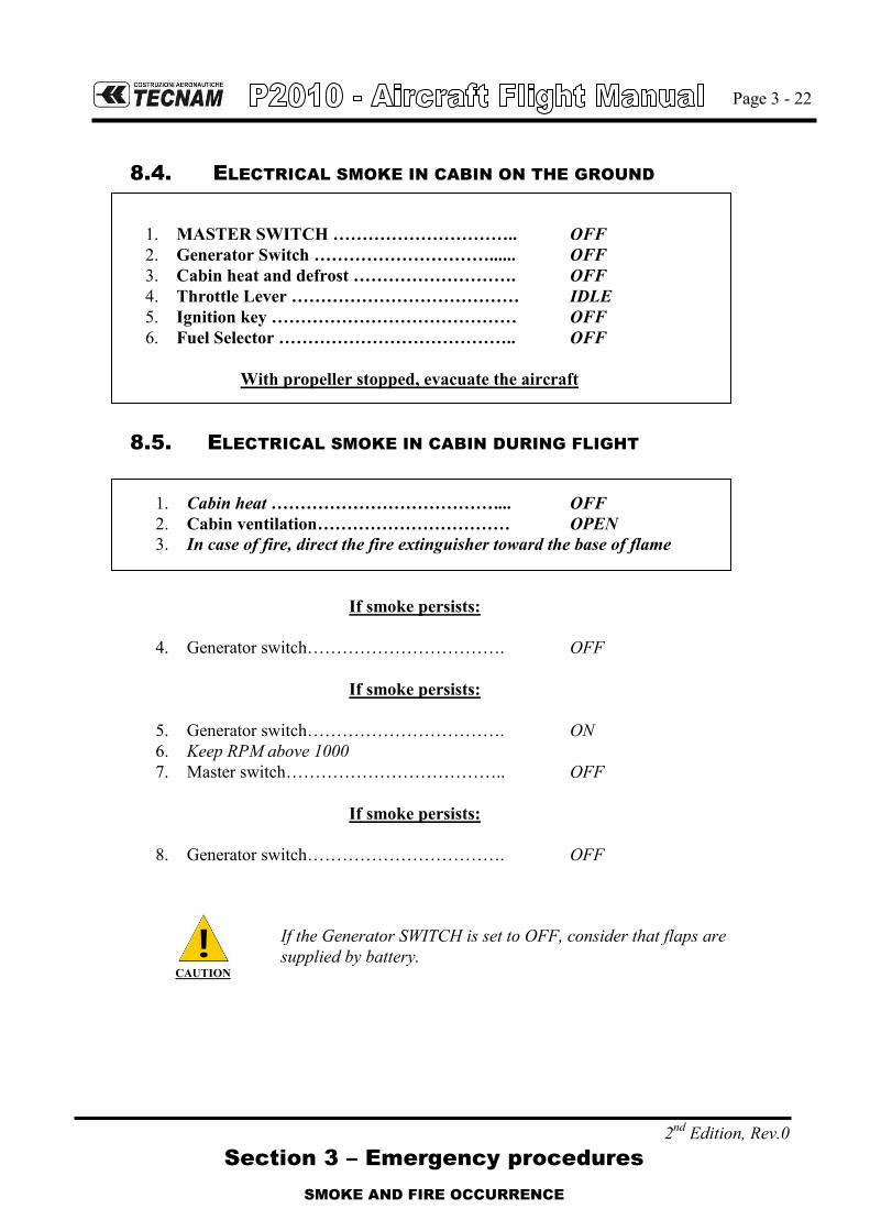
8.4. ELECTRICAL SMOKE IN CABIN ON THE GROUND
1. MASTER SWITCH ………………………….. OFF 2. Generator Switch …………………………...... OFF 3. Cabin heat and defrost ………………………. OFF 4. Throttle Lever ………………………………… IDLE 5. Ignition key …………………………………… OFF 6. Fuel Selector ………………………………….. OFF
With propeller stopped, evacuate the aircraft
8.5. ELECTRICAL SMOKE IN CABIN DURING FLIGHT
1. Cabin heat …………………………………... OFF 2. Cabin ventilation…………………………… OPEN 3. In case of fire, direct the fire extinguisher toward the base of flame
If smoke persists:
4. Generator switch……………………………. OFF
If smoke persists:
5. Generator switch……………………………. ON 6. Keep RPM above 1000 7. Master switch……………………………….. OFF
If smoke persists:
8. Generator switch……………………………. OFF
CAUTION
If the Generator SWITCH is set to OFF, consider that flaps are supplied by battery.

Page 3 - 23
2nd Edition, Rev.0
Section 3 – Emergency procedures
UNINTENTIONAL SPIN RECOVERY
9. RECOVERY FROM UNINTENTIONAL SPIN
If unintentional spin occurs:
1. Throttle …………………………… Idle 2. Rudder …………………………………… Fully opposite to the direction of spin 3. Control Yoke …………………………….. Centralize and hold neutral
When rotation stops: 4. Rudder …………………………………… Neutral 5. Attitude ……………………………………. Recovery promptly but smoothly,
averting speed close to/in excess of VNE
6. Throttle ……………………………………..As required
WARNING
Keep full rudder against rotation until spin has stopped.
One complete turn and recovery will take about 800 to 1000 feet alti-tude loss.

Page 3 - 24
2nd Edition, Rev.0
Section 3 – Emergency procedures
INTENTIONALLY LEFT BLANK

Page 3 - 25
2nd Edition, Rev.0
Section 3 – Emergency procedures
OTHER EMERGENCIES
10. OTHER EMERGENCIES
10.1. LOSS OF ESSENTIAL BUS
In case of loss of essential bus, the following will be lost (related breakers are listed):
PFD FLAP ACTUATOR
COM1 PITOT HEAT
GPS1/NAV1 STROBE LIGHT
EIS LANDING LIGHT
FUEL PUMP AHRS
FIELD ADC
STALL WARNING ANN. PANEL
Electrical power from Alternator is lost, battery will automatically provide energy (duration at least 30 min.).
Pilot will need to make reference to standby instrument for primary flight infor-mation and parameters.
Pilot will be able to use the audio panel and COM2/NAV2 via MFD.
Engine parameters and related warnings/cautions are lost.
Flaps extension and retraction will be lost, apply Flaps control failure procedure (See Para 10.6).
Strobe and landing lights will be lost, NAV and taxi lights are still available; taxi light will be the only visual aid for landing in night conditions.
10.2. LOSS OF MAIN BUS
In case of loss of main bus, the main bus voltage will drop to zero.
The following will be lost (related breakers are listed):
AUDIO PANEL INSTR. LIGHT AVIONIC
XPDR NAV LIGHT MFD
A.D.I. (available running on internal bat-tery power)
TAXI LIGHT COM2
FAN (G1000) 28/12 VDC CONVERTER GPS2/NAV2
CABIN LIGHT RUDDER TRIM ACTUATOR ADF
START 12VDC SOCKET DME
INSTRUMENT (clock, pitch trim indic.)
Fail safe operation of Garmin G1000 allows pilot to transmit and use COM1 using headphones only; speakers will not be available
For night flights, all instrument lights will be lost, but emergency light will still be available.

Page 3 - 26
2nd Edition, Rev.0
Section 3 – Emergency procedures
OTHER EMERGENCIES
10.3. ELECTRICAL SYSTEM OVERALL FAILURE
In case of electrical system overall failure, apply following procedure:
1. MASTER SWITCH ……………………. OFF 2. Generator Switch …………………… OFF 3. MASTER SWITCH ……………………. ON 4. Generator Switch …………………… ON
If failure persists
Land as soon as possible
Standby instrument is still available, providing the internal bat-tery is in good charge status (>80%) it will provide at least 1 hr of runtime.
WARNING
An electrical system overall failure prevents flaps operation: landing distance without flaps increases of about 25% (See also Para 10.6).
10.4. STATIC PORT FAILURE
In case failure, the alternate static port in the cabin must be activated.
In this case apply following procedure:
1. Cabin ventilation ………………………….. OFF (hot and cold air) 2. ALTERNATE STATIC PORT VALVE …. OPEN 3. Continue the mission
NOTE

Page 3 - 27
2nd Edition, Rev.0
Section 3 – Emergency procedures
OTHER EMERGENCIES
10.5. UNINTENTIONAL FLIGHT INTO ICING CONDITIONS
1. Pitot heat ……...………….. ON 2. Immediately fly away from icing conditions (changing altitude and direc-
tion of flight, out and below of clouds, visible moisture, precipitations). 3. Control surfaces …………. Move continuously to avoid locking 4. Throttle……………………. INCREASE to prevent ice build-up on propeller
blades
WARNING
In event of ice build-up in correspondence of wing leading edg-es, stall speed increases and stall may become asymmetric. In case of stabilator ice accretion, it may loose its efficiency, lead-ing to lack of aircraft pitch control and loss of control.
10.6. FLAPS CONTROL FAILURE
DURING TAKEOFF
CAUTION
In case of unintentional flaps retraction, or if the flaps control fails, and if the takeoff cannot be aborted, consider that the dis-tances, without flaps, increase by about 20%.
1. Flap position………………. Check and confirm 2. Airspeed ………………….. Below 91 KIAS (VFE) 3. Land as soon as practical
DURING APPROACH/LANDING
CAUTION
In case of unintentional flaps retraction or if the flaps control fails, consider that the landing distance without flaps increases by about 25%.
1. Flap position………………. Check and confirm 2. Airspeed …………………… 80 KIAS during approach 3. Land as soon as practical

Page 3 - 28
2nd Edition, Rev.0
Section 3 – Emergency procedures
OTHER EMERGENCIES
10.7. ELECTRICAL RUDDER TRIM CONTROL FAILURE
Trim Runaway
In event of trim runaway: 1. Speed: adjust to control aircraft without excessive pedal force 2. Rudder: As required 3. Land aircraft as soon as practical.
Trim Jamming
Should trim control be jammed / inoperative: 1. Breaker: CHECK IN 2. Speed: adjust to control aircraft without excessive pedal force 3. Rudder: As required 4. Land aircraft as soon as practical.

Page 3 - 29
2nd Edition, Rev.0 Section 3 – Emergency procedures
LANDING EMERGENCIES
11. LANDING EMERGENCIES
11.1. FORCED LANDING WITHOUT ENGINE POWER
Preparation: 1. Flaps…………………………………. UP 2. Best Glide Speed ……………………. 85KTS 3. Radio ………………………………… Transmit MAYDAY giving
location and intentions 4. Transponder …………………………. 7700 5. If off airport, ELT …………………… ON 6. Find a suitable place to land safely, plan to approach it upwind 7. Throttle Lever ………………………. IDLE 8. Mixture ……………………………… CUTOFF 9. Fuel Selector ………………………... OFF 10. Ignition key …………………………. OFF 11. Fuel pump …………………………… OFF 12. Seat belts ……………………………. Tightly fastened When landing is assured: 13. Flaps ………………………………… As required 14. Generator and Master switches ..……. OFF
Be prepared for aircraft evacuation (Para 4).
11.2. POWER-ON FORCED LANDING
1. Flaps…………………………………. UP 2. Best Glide Speed ……………………. 85KTS 3. Locate the most suitable terrain for emergency landing, plan to approach upwind 4. Safety belts……………..……………… Tightly fastened When landing is assured: 5. Flaps …………………………………... As necessary 6. Fuel selector valve…………………….. OFF 7. Electric Fuel Pump……………………. OFF 8. Ignition Key…………………………… OFF 9. Generator and Master switches……….. OFF
NOTE

Page 3 - 30
2nd Edition, Rev.0 Section 3 – Emergency procedures
LANDING EMERGENCIES
11.3. LANDING WITH NOSE LANDING GEAR TIRE DEFLATED
1. Pre-landing checklist: Complete 2. Flaps: Land 3. Land and maintain aircraft NOSE HIGH attitude as long as possible.
As aircraft stops
4. Engine securing: Perform(see Para. 5) 5. Airplane evacuation: Perform(see Para 4)
11.4. LANDING WITH A MAIN LANDING GEAR TIRE DEFLATED
1. Pre-landing checklist: Complete 2. Flaps: Land 3. Land the aeroplane on the side of runway opposite to the defective tire to
compensate the change in direction which is to be expected during final rolling (put the drag in the middle)
4. Touchdown with the GOOD TIRE FIRST and hold aircraft with the flat tire off the ground as long as possible by mean of aileron and rudder con-trol.
As aircraft stops
5. Engine securing: Perform(see Para. 5) 6. Airplane evacuation: Perform(see Para. 4)

Section 4 – Normal procedures
INDEX
Page 4 - 1
2nd Edition, Rev. 0
SECTION 4 – NORMAL PROCEDURES
INDEX
1. INTRODUCTION ....................................................................................... 3
2. IFR flight: training pre-requisites and incremental
exposition to G1000 suite ................................................................... 4
3. AIRSPEEDS FOR NORMAL OPERATIONS ........................................ 7
4. PRE-FLIGHT INSPECTION .................................................................... 9
4.1. Cabin Inspection ........................................................................... 9
4.2. Aircraft Walk-around ................................................................... 10
5. CHECKLISTS .......................................................................................... 15
5.1. Before Starting engine (After Preflight Inspection) .................... 15
5.2. Engine Starting ........................................................................... 16
5.3. Before taxiing ............................................................................. 17
5.4. Taxiing ........................................................................................ 18
5.5. Before takeoff ............................................................................. 19
5.6. Takeoff ........................................................................................ 20
5.7. Climb ........................................................................................... 21
5.8. Cruise .......................................................................................... 22
5.9. Mixture adjustment recommendation ........................................ 22
5.10. Descent ....................................................................................... 23
5.11. Before landing ............................................................................. 24
5.12. Balked landing/missed approach ................................................ 24
5.13. Go-around .................................................................................... 24
5.14. After landing ............................................................................... 24
5.15. Engine shut down ........................................................................ 25
5.16. Postflight checks ........................................................................ 25
5.17. FLIGHT IN RAIN .......................................................................... 26
5.18. REFUELLING ............................................................................... 26
5.19. FLIGHT AT HIGH ALTITUDE ........................................................ 26

Section 4 – Normal procedures
2nd Edition, Rev. 0
Page 4 - 2
INTENTIONALLY LEFT BLANK

Section 4 – Normal procedures
INTRODUCTION
2nd Edition, Rev. 0
Page 4 - 3
1. INTRODUCTION
Section 4 describes checklists and recommended procedures for the conduct of normal operations for P2010 aircraft.

Section 4 – Normal procedures
IFR FLIGHT: TRAINING PRE-REQUISITES AND INCREMENTAL
EXPOSITION TO G1000 SUITE
2nd Edition, Rev. 0
Page 4 - 4
2. IFR FLIGHT: TRAINING PRE-REQUISITES AND INCREMENTAL EX-
POSITION TO G1000 SUITE
The aircraft is fully equipped with a Garmin G1000 avionic suite that integrates radio aids navigation with GPS navigation, providing an outstanding capability to support IFR flight, from basic instrument training to complex IFR scenario. Depending on national regulations, in some countries flying IFR with a single en-gine aircraft without autopilot installation and/or single pilot may or may not be allowed, any customer must pay careful attention to check limitations that may apply. The use of G1000 software requires full system knowledge (G1000 manual which will also specify peculiar limitations), careful preparation, ground training on the computer-assisted software and pre-flight training before flight. Furthermore, as a minimum during training, it’s strongly recommended using the avionic suite in IFR with incremental steps after initial basic IFR instruction:
1. Initial use of a single radio-aids (No GPS); 2. Use of two radio-aids (No GPS); 3. Use of GPS for point to point navigation (No approaches); 4. Use of VNAV feature; 5. Full use of avionic suite.
The flight training syllabus for IFR instruction will need to address this incremen-tal approach in order to give pilots awareness of full avionic potential, and to highlight the complexity of single pilot usage of G1000 Garmin suite while en-route or high density airspace structure.
CAUTION
Due to precision required on IFR flight, the workload that may develop using full avionic suite, may get excessive in single pilot without the aid of an autopilot. Considering the complexity of the G1000 suite, sound judgment will be required (weather, airspace complexity, pilot skills) to assess the best option of IFR steer guidance.
NOTE

Section 4 – Normal procedures
IFR FLIGHT: TRAINING PRE-REQUISITES AND INCREMENTAL
EXPOSITION TO G1000 SUITE
2nd Edition, Rev. 0
Page 4 - 5
The necessity to correct or modify flight plans in the Garmin G1000 under these conditions may distract pilots from basic handling causing deviations from as-signed parameters, so careful attention must be exercised to avoid deviations on flying parameters. It’s highly recommended to continue cross-checking flight parameters when en-tering flight data into the G1000, especially when trying to create / insert arrival and departure procedures and / or VNAV profiles as the quantity of actions need-ed is high and may distract pilots from basic and precise handling. The following prescriptions, other than those already present in the G1000 manu-al, shall be observed: - Use of GPS for precision approach navigation mode is not allowed. - Use of GPS is prohibited as primary means for navigation. GPS is approved as sup-
plemental means for navigation; - Use of GPS is prohibited for IFR in terminal area or in non-precision approach op-
erations;
If Receiver Autonomous Integrity Monitoring (RAIM) function becomes unavail-able in en route phase of flight, position must be verified every 15 minutes using other IFR approved navigation system.
Turbulence and / or crosswind: Presence of moderate to heavy turbulence and / or strong crosswind conditions (above 20 kts crosswind) will require high drift angle to correct for wind (above 15° drift) and highly reduce spare capabilities to do other concurrent tasks inside the cockpit other than precise flying.
NOTE

Page 4 - 6
Section 4 – Normal procedures
2nd Edition, Rev. 0
INTENTIONALLY LEFT BLANK

Section 4 – Normal procedures
AIRSPEED FOR NORMAL OPERATIONS
2nd Edition, Rev. 0
Page 4 - 7
3. AIRSPEEDS FOR NORMAL OPERATIONS
The following airspeeds are those which are significant for normal operations.
FLAPS 1160 kg (2557 lb)
Rotation Speed (VR) T/O 60 KIAS
Best Angle-of-Climb Speed (VX) T/O 65 KIAS
Best Angle-of-Climb Speed (VX) 0° 76 KIAS
Best Rate-of-Climb speed (VY) 0° 82 KIAS
Flaps (VFE) T/O & LAND 91 KIAS
No flaps approach 0° 80 KIAS
Approach speed T/O 75 KIAS
Final Approach Speed FULL 70 KIAS
Manoeuvring speed (VA) 0° 120 KIAS
Glide Speed (Vglide) 0° 85 KIAS
Never Exceed Speed (VNE) 0° 166 KIAS

Page 4 - 8
Section 4 – Normal procedures
2nd Edition, Rev. 0
INTENTIONALLY LEFT BLANK

Section 4 – Normal procedures
Pre-flight Inspection
2nd Edition, Rev. 0 0
Page 4 - 9
4. PRE-FLIGHT INSPECTION
Before each flight, it is necessary to carry out a complete aircraft check including a cabin inspection followed by an external inspection, as below detailed.
4.1. CABIN INSPECTION
1. Aircraft documents (ARC, Certificate of Airworthiness, Noise certificate, Radio COM certificate, AFM): check current and on board
2. Weight and balance: calculate (ref. to Section 6) and check within limits 3. Breaker: all IN 4. Safety belts: connected to hard points, check condition 5. Ignition key: OFF, key extracted 6. Master switch: ON 7. Voltmeter: check within the limits 8. Lights: all ON, check for operation 9. Acoustic stall warning: check for operation 10. Master switch: OFF 11. Baggage: check first aid kit, ELT, fire extinguisher, luggage secured with
restraint net.

Section 4 – Normal procedures
Pre-flight Inspection
2nd Edition, Rev. 0 0
Page 4 - 10
4.2. AIRCRAFT WALK-AROUND
To perform the aircraft walk-around, carry out the checklists according to the pattern shown in Figure 4-1.
WARNING
Visual inspection is defined as follows: check for defects, cracks, detachments, excessive play, unsafe or improper installation as well as for general condition. For control surfaces, visual in-spection also involves additional check for freedom of movement and security. Red lubber lines on bolts and nuts shall be intact.
WARNING
Fuel level indicated by the fuel quantity indicators must be veri-fied by visual check of actual fuel quantity embarked in the tanks: graduated dipstick must be used.
WARNING
If ignitions key is in L/R/BOTH position, a propeller movement can cause the engine starting with consequent hazard for people nearby.
Fuel drainage operation must be carried out with the aircraft parked on a level surface. Set Cockpit Fuel Selector Valve to OFF prior to drain fuel.
NOTE

Section 4 – Normal procedures
Pre-flight Inspection
2nd Edition, Rev. 0 0
Page 4 - 11
ABCD
E GF
H
I
L M N
OPQ
R
S
T
U
V
Z
Figure 4.1
A Left fuel filler cap CHECK desired fuel level (use graduated
dipstick). Drain the left fuel tank sump by quick drain valve using a cup to collect fuel (drainage operation must be carried with the aircraft parked on a level surface). Check for water or other contaminants. Make sure filler cap is closed.
B Pitot tube REMOVE pitot plug and check the pitot for obstructions. Do not blow inside pitot tube.
C Left side leading edge and wing skin
Visual inspection, check stall strips (if pre-sent)
D Left strobe light Visual inspection, CHECK for integrity and fixing
E Left aileron, hinges and LH tank vent line
CHECK aileron and hinges for damage, and freedom from plays; Copper bonding strips: CHECK for proper connection; Left tank vent: CHECK for obstructions.
F Left flap and hinges Visual inspection; Copper bonding strips: CHECK for proper connection.

Section 4 – Normal procedures
Pre-flight Inspection
2nd Edition, Rev. 0 0
Page 4 - 12
G Left main landing gear CHECK inflation, tire condition, alignment, fuselage skin condition. Check fuselage skin status, tire status (cuts, bruises, cracks and excessive wear), slippage markers integrity, gear structure and brakes hoses: there should be no sign of hydraulic fluid leakage.
H Stabilator, tab and rear light CHECK stabilator leading edge. Check the actuating mechanism of stabilator and the connection with related tab: CHECK free of play, friction. CHECK fuselage bottom and top skin. CHECK antennas for integrity. Check light for integrity.
I Vertical tail and rudder Visual inspection, check free of play, friction.
L Right main landing gear CHECK inflation, tire condition, alignment, fuselage skin condition. Check fuselage skin status, tire status (cuts, bruises, cracks and excessive wear), slippage markers integrity, gear structure and brakes hoses: there should be no sign of hydraulic fluid leakage.
M Right flap and hinges Visual inspection; Copper bonding strips: CHECK for proper connection;
N Right aileron, hinges and RH tank vent line
Visual inspection, check free of play, friction; Copper bonding strips: CHECK for proper connection; Right side tank vent: check for obstructions.
O Right strobe light, leading edge and wing skin
Visual inspection, CHECK stall strips (if pre-sent), CHECK strobe light for integrity and fixing
P Stall indicator switch CHECK for integrity and free of play,
Q Right fuel filler cap CHECK desired fuel level (use graduated dipstick). Drain the right fuel tank sump by quick drain valve using a cup to collect fuel (drainage operation must be carried with the aircraft parked on a level surface). Check for water or other contaminants. Make sure filler cap is closed.
R Nose wheel strut and tire/ RH static port
CHECK inflation, tire condition and condi-tion of shock absorber: there should be no sign of hydraulic fluid leakage. Check the right static port for obstructions.
Section 4 – Normal procedures
Pre-flight Inspection
2nd Edition, Rev. 0 0
Page 4 - 13
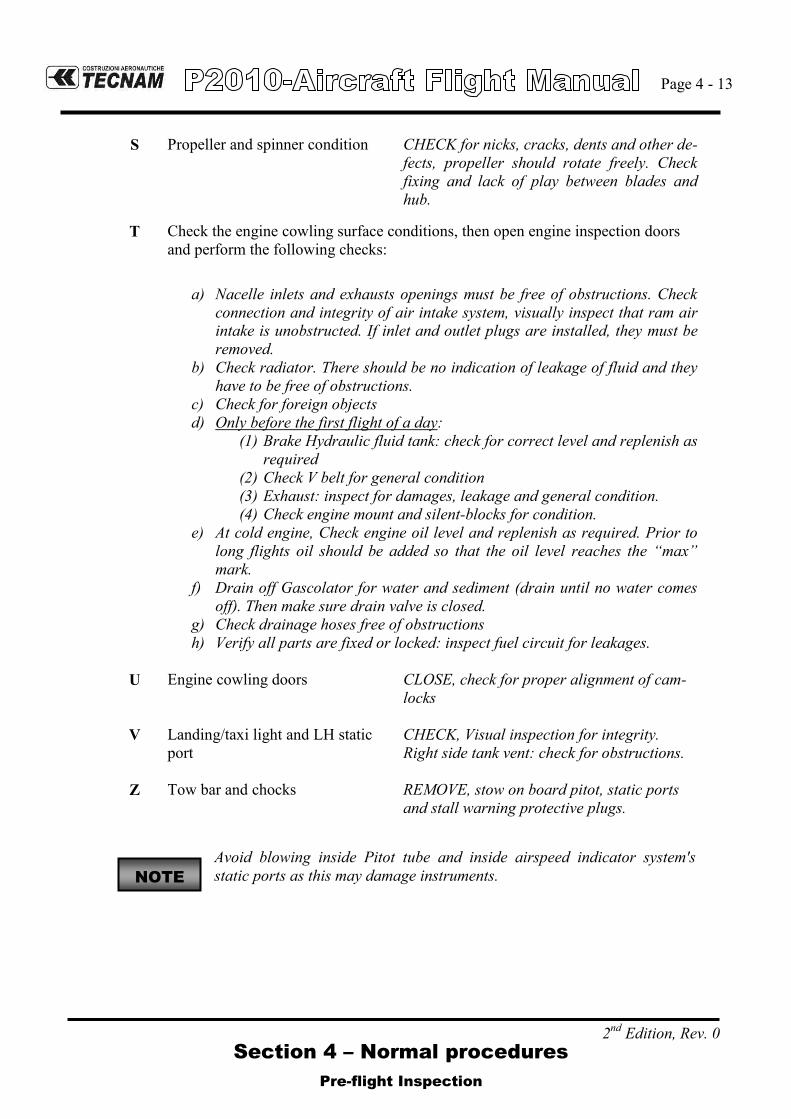
S Propeller and spinner condition CHECK for nicks, cracks, dents and other de-fects, propeller should rotate freely. Check fixing and lack of play between blades and hub.
T Check the engine cowling surface conditions, then open engine inspection doors and perform the following checks:
a) Nacelle inlets and exhausts openings must be free of obstructions. Check connection and integrity of air intake system, visually inspect that ram air intake is unobstructed. If inlet and outlet plugs are installed, they must be removed.
b) Check radiator. There should be no indication of leakage of fluid and they have to be free of obstructions.
c) Check for foreign objects d) Only before the first flight of a day:
(1) Brake Hydraulic fluid tank: check for correct level and replenish as required
(2) Check V belt for general condition (3) Exhaust: inspect for damages, leakage and general condition. (4) Check engine mount and silent-blocks for condition.
e) At cold engine, Check engine oil level and replenish as required. Prior to long flights oil should be added so that the oil level reaches the “max” mark.
f) Drain off Gascolator for water and sediment (drain until no water comes off). Then make sure drain valve is closed.
g) Check drainage hoses free of obstructions h) Verify all parts are fixed or locked: inspect fuel circuit for leakages.
U Engine cowling doors CLOSE, check for proper alignment of cam-
locks
V Landing/taxi light and LH static port
CHECK, Visual inspection for integrity. Right side tank vent: check for obstructions.
Z Tow bar and chocks REMOVE, stow on board pitot, static ports and stall warning protective plugs.
Avoid blowing inside Pitot tube and inside airspeed indicator system's static ports as this may damage instruments. NOTE

Page 4 - 14
Section 4 – Normal procedures
2nd Edition, Rev. 0 0
INTENTIONALLY LEFT BLANK
Section 4 – Normal procedures
Checklists
2nd Edition, Rev. 0
Page 4 - 15
5. CHECKLISTS
5.1. BEFORE STARTING ENGINE (AFTER PREFLIGHT INSPECTION)
1. Seat position and safety belts: adjust 2. Flight controls: operate full stroke checking for movement smoothness, free of
play and friction. 3. Parking brake: engage 4. Throttle friction: adjust 5. Throttle: IDLE 6. Mixture control Lever: LEAN 7. Circuit Breakers: check all IN 8. Master switch: ON, wait PFD turn on, Check ALT OUT caution ON, Check LOW
FP and LOW OP warning ON 9. Only before the first flight of the day:
Standby Instrument: Check no red crosses displayed. a. Press and hold the control knob (approx. 2 sec) b. Rotate the knob selecting “INFO>” page then press it c. Select “BATTERY INFO” page then press the knob d. Check “CHARGE (%)” to be more than 80%, then exit menu
10. Avionic Master switch: ON, wait MFD turn on, check instruments, check Voltage on Main and Essential Buses.
11. Fuel quantity: compare the fuel quantity indicators information with fuel quantity visually checked into the tanks (see Pre-flight inspection – External inspection, and update the Garmin fuel content in the totalizer accordingly
The totalizer function available on Garmin Engine page allows input only up to 230lts (maximum usable fuel). Fuel calculations on totalizer do not use the air-craft fuel quantity indicators and are calculated from the last time the fuel was re-set. Fuel consumption on totalizer is very precise as it take instantaneous fuel flow for the computation.
12. Electric fuel pump: ON (check for audible pump noise and increase of fuel pressure) 13. Warning “LOW FUEL PRESSURE”: extinguished 14. Electric fuel pump: OFF 15. Flap control: cycle fully extended and then set to T/O 16. Pitch Trim: cycle fully up and down, then set to NEUTRAL 17. Rudder trim: cycle full right and left, then set to NEUTRAL
WARNING
Pitch trim position other than in neutral position would affect take off per-formance and take off rotation execution at the correct VR.
18. Nav & Strobe lights: ON
In absence of RH seat occupant: fasten seat belts around the seat so as to pre-vent any interference with the aeroplane flight control operation and with rap-id egress in an emergency.
19. Doors: Closed and locked
NOTE
NOTE

Section 4 – Normal procedures
Checklists
2nd Edition, Rev. 0
Page 4 - 16
5.2. ENGINE STARTING
(a) Cold engine 1. Engine throttle: 1cm (1/2 inch) above idle 2. Fuel selector valve: select the tank with less fuel 3. Electric fuel pump: ON 4. Mixture: full open for 3 – 5” (positive fuel flow indication) then CUT-OFF 5. Propeller area: check that area is clear of persons / objects
WARNING
Check to insure no person or object is present in the area close to the propeller. Forward lower sector visibility is not possible from inside the cockpit.
CAUTION
Do not overheat the starter motor. Do not operate it for more than 10 seconds. After operating the starter motor, let it cool off for 20 seconds. After 6 attempts to start the engine, let the starter cool off for half an hour.
6. Ignition key: BOTH 7. Ignition key: START 8. Mixture: rapidly move to FULL RICH 9. Throttle: set 1000 – 1200 RPM 10. Check oil pressure rises within 10 sec. 11. Check “OIL PRESSURE LOW”: extinguished 12. Electric fuel pump: OFF 13. Check fuel pressure: within limits 14. Generator switch: ON 15. Voltmeter: increase and check within green arc 16. ALT FAIL caution: extinguished 17. Nav. and taxi light: ON
Avoid idling operations on the ground for optimum engine operation, maintain 1000-1200 RPM, do not exceed 2200 RPM on the ground.
18. Engine instruments: Check within limits 19. Check G1000 for warning / caution messages
NOTE

Section 4 – Normal procedures
Checklists
2nd Edition, Rev. 0
Page 4 - 17
(b) Warm engine 1. Engine throttle: IDLE 2. Fuel selector valve: select the tank with less fuel 3. Electric fuel pump: ON 4. Propeller area: check for area clear of persons / objects
WARNING
Check to insure no person or object is present in the area close to the propel-ler. Forward lower sector visibility is not possible from inside the cockpit.
CAUTION
Do not overheat the starter motor. Do not operate it for more than 10 se-conds. After operating the starter motor, let it cool off for 20 seconds. After 6 attempts to start the engine, let the starter cool off for half an hour.
5. Ignition key: BOTH 6. Ignition key: START 7. Mixture: rapidly to FULL RICH 8. Throttle: set 1000 – 1200 RPM 9. Check oil pressure rises within 10 sec. 10. Electric fuel pump: OFF 11. Check fuel pressure within limits 12. Generator switch: ON 13. Voltmeter: increase and check within green arc 14. ALT FAIL caution: extinguished 15. Engine instruments: check within green arc 16. Check G1000 for warning / caution messages
Avoid idling operations on the ground for optimum engine operation, maintain 1000-1200 RPM, do not exceed 2200 RPM on the ground.
5.3. BEFORE TAXIING
1. Flight instruments and avionics: set, TEST functions 2. Altimeter: set 3. Pitot Heat: ON, test for ammeter indication, then OFF 4. Parking brake: OFF
CAUTION
When taxiing at close range to other aircraft, or during night flight in clouds, fog or haze, the strobe lights should be switched OFF. The NAV lights must always be switched ON during night procedures.
NOTE

Section 4 – Normal procedures
Checklists
2nd Edition, Rev. 0
Page 4 - 18
5.4. TAXIING
1. Parking brake: Release 2. Brakes: check 3. Flight instruments: check altimeter.
Avoid prolonged idling during taxi.
CAUTION
Alternator lights may appear when reducing engine RPM below 950 RPM (yellow arc). The light will stay ON until RPM is increased above. During taxi, it is recommended to maintain propeller speed at 1000RPM or above in order to preserve a full loaded battery, minimise annunciator nuisance and assure max-imum battery performance during flight.
CAUTION
Following extended operation on the ground, or at high ambient temperatures, the following indications of fuel vapor lock may appear: - Arbitrary changes in idle RPM and fuel flow; - Slow reaction of the engine to operation of throttle; - Engine will not run with throttle in IDLE position. Solution: 1. For about 1 to 2 minutes, or until the engine settles, run at a speed of 1800 to 2000 RPM. Oil and cylinder head temperatures must stay within limits. 2. Pull throttle back to IDLE to confirm smooth running. 3. Set throttle to 1200 RPM and mixture for taxiing, i.e., use mixture control lever to set the maximum RPM attainable. 4. Immediately before the take-off run set the mixture for take-off, apply full throt-tle and hold this position for 10 seconds.
Vapor lock can be avoided if the engine is run at speeds of 1800 RPM or more.
NOTE
NOTE

Section 4 – Normal procedures
Checklists
2nd Edition, Rev. 0
Page 4 - 19
5.5. BEFORE TAKEOFF
1. Parking brake: brake pedal press, ON 2. Engine instruments: Check within limits 3. ALT OUT caution: OFF (check) 4. Electric Fuel pump: ON 5. Fuel selector valve: select the fullest tank 6. Fuel pressure: check 7. Mixture: FULL RICH
For 5000ft density altitude and above, or high ambient temperatures, a FULL RICH mixture may cause rough running of the engine or a loss of performance. The mixture may be adjusted to obtain smooth engine operations.
8. Throttle: set 1500 RPM a. Alternate Air check:
Alternate Air: PULL (Check drop 50-100 RPM) b. Mixture check:
Mixture: reduce
EGT: check increase
FF: check decrease
Mixture: FULL RICH 9. Throttle: 2100 RPM 10. Magneto Check: L – BOTH – R – BOTH
Max RPM drop: 175 RPM
Max. difference: 50 RPM 11. Throttle: Idle 12. Flaps: check T/O 13. Pitch and Rudder trim: check neutral 14. Flight controls: check free 15. Seat belts: check fastened 16. Doors: check closed and locked 17. Parking brake: Release 18. Landing light: ON as required 19. XPDR: ON
NOTE

Section 4 – Normal procedures
Checklists
2nd Edition, Rev. 0
Page 4 - 20
5.6. TAKEOFF
For 5000ft density altitude and above, or high ambient temperatures, a FULL RICH mixture may cause rough running of the engine or a loss of performance. The mixture may be ad-justed to obtain smooth engine operations. Lean to maximum RPM at Full Throttle prior to take-off where airports are at 5000ft density altitude or higher. During climb, a rough method of correctly leaning is to slowly reduce mixture lever until an increase of appr.ly 50-100 RPM is noticed at constant IAS or EGT reaches 1375°F mark.
1. Pitot HEAT: ON if required 2. Fuel pump: ON 3. Brakes: apply
4. Throttle: FULL and check approximately 2100 100 RPM
WARNING
Engine proper performance at full throttle shall be checked early in the ground roll in order to abandon take-off if necessary. A rough engine, sluggish RPM increase or failure to reach take-off RPM are reasons for abandoning the take-off. If the engine oil is cold, an oil pressure in the yellow sec-tor is permissible.
5. Engine instruments: check parameters within the limits 6. Brakes: Release 7. Rotation speed VR: 60 KIAS
At safe height: 8. Flaps: retract (minimum speed 73 KIAS)
Expect to adjust pitch trim (pitch up) when retracting flaps after take-off.
9. Establish Climb rate VY: 82 KIAS 10. Electrical fuel pump: OFF 11. Fuel pressure: check within limits
NOTE
NOTE

Section 4 – Normal procedures
Checklists
2nd Edition, Rev. 0
Page 4 - 21
5.7. CLIMB
Due to position of fuel sensors, during climb fuel gauges in cockpit will indicate a fuel quantity slightly lower than the real amount. Regaining level flight will immediately restore correct indications.
For 5000ft density altitude and above, or high ambient temperatures, a FULL RICH mixture may cause rough running of the engine or a loss of performance. The mixture may be adjusted to obtain smooth engine operations. Lean to maximum RPM at Full Throttle prior to take-off where airports are at 5000ft density altitude or higher. During climb, a rough method of correctly leaning is to slowly reduce mixture lever until an increase of appr.ly 50-100 RPM is noticed at constant IAS or EGT reaches 1375°F mark.
1. Flaps: UP (minimum speed 73KIAS)
Expect to adjust pitch trim (pitch up) when retracting flaps after take-off
2. Establish climb Vy: 82KIAS 3. Electrical fuel pump: OFF 4. Fuel pressure: check within limits 5. Throttle: FULL 6. MIXTURE: RICH, above 5000ft keep EGT constant 7. Engine instruments: in the GREEN
If the fuel pressure warning light illuminates, or the fuel pressure indication is below green arc, the electrical fuel pump must be switched ON.
NOTE
NOTE
NOTE
NOTE

Section 4 – Normal procedures
Checklists
2nd Edition, Rev. 0
Page 4 - 22
5.8. CRUISE
1. Power: set performance as required, refer to table in section 5 of AFM 2. Fuel tank selector: as required to maintain symmetric balance 3. Mixture: set in accordance with following para 5.9
To optimize engine life, the cylinder head temperature (CHT) should lie between 150°F and 400°F in continuous operation, and not rise above 435°F in fast cruise.
Monitor and manually compensate asymmetrical fuel consumption by switching fuel selector valve. Switch ON the electric fuel pump prior to swap the fuel feeding from one tank to another.
5.9. MIXTURE ADJUSTMENT RECOMMENDATION
CAUTION
The maximum permissible cylinder head temperature (500 °F) must never be ex-ceeded. The mixture control lever should always be moved slowly. Before selecting a higher power setting the mixture control lever should, on each occasion, be moved slowly to fully RICH before throttle adjustment. Care should always be taken that the cylinders do not cool down too quickly. The cooling rate should not exceed 50 °F per minute.
For maximum service life cylinder head temperature should be kept below 475 °F (high performance cruise) and below 435 °F (for economy cruise).
Best Cruise Economy Mixture The best economy mixture setting may only be used up to a power setting of 75 %. In order to obtain the lowest specific fuel consumption at a particular power setting, proceed as follows:
- Slowly pull the mixture control lever back towards LEAN until the engine starts to run rough-ly.
- Then push the mixture control lever forward just far enough to restore smooth running. At the same time the exhaust gas temperature (EGT) should reach a maximum.
Best Cruise Power Mixture The mixture can be set for maximum performance at all power settings:
- The mixture should first be set as for best economy. - The mixture should then be enriched until the exhaust gas temperature is approximately
100°F lower. This mixture setting produces the maximum performance for a given manifold pressure and is mainly used for high power settings (approximately 75 %).
NOTE
NOTE
NOTE

Section 4 – Normal procedures
Checklists
2nd Edition, Rev. 0
Page 4 - 23
5.10. DESCENT
Due to position of fuel sensors, during descent fuel gauges in cockpit will indicate a fuel quantity slightly higher than the real amount. Regaining level flight will immediately re-store correct indications.
1. Mixture control: slowly full rich 2. Throttle: reduce as required
Shock cooling shortens engine life. When reducing power, the change in cylinder head temperature should not exceed 50°F per minute. In order to ensure best practice and avoid potential illumination of ALT FAIL (due to low propeller speed), the following best practice should be observed: - Reducing power to maintain a minimum descent speed of 82 KIAS (best glide) and / or
a blade angle to maintain 850 RPM; - Opening the ALTER AIR command to full open (to avoid ice accretion).
CAUTION
The maximum permissible cylinder head temperature (500 °F) must never be exceeded. The mixture control lever should always be moved slowly. Before selecting a higher power setting the mixture control lever should, on each occasion, be moved slowly to fully RICH. Care should always be taken that the cylinders do not cool down too quickly. The cooling rate should not exceed 50 °F per minute.
NOTE
NOTE

Section 4 – Normal procedures
Checklists
2nd Edition, Rev. 0
Page 4 - 24
5.11. BEFORE LANDING
1. Electric fuel pump: ON 2. Fuel valve: select the fullest tank 3. Landing Light: ON On downwind, leg abeam touch down point: 4. Flaps: set T/O (below 90KIAS)
Expect to adjust pitch trim (pitch down) when extending flaps to T/O or LAND
5. Approach speed: set On final leg, before landing: 6. Mixture control lever: RICH 7. Flaps: LAND 8. Final Approach Speed: set 9. Optimal touchdown speed: 60 KIAS
Upon flaring the aircraft has the tendency to float before touching wheels down. Taking into account local environmental constraints, consider the possibility to adjust aiming point for a better touchdown point control.
CAUTION
In conditions such as (e.g.) strong wind, danger of windshear or turbulence a higher approach speed shall be selected..
5.12. BALKED LANDING/MISSED APPROACH
1. Throttle: FULL 2. Speed: keep over 80 KIAS, climb to VY or VX as applicable 3. Flaps position: T/O Above a safe height: 4. Landing lights: OFF
5.13. GO-AROUND
1. Throttle: FULL 2. Speed: keep over 80 KIAS, climb to VY or VX as applicable 3. Flaps position: T/O
5.14. AFTER LANDING
1. Throttle: Idle 2. Brakes: apply 3. Pitot heat: OFF (if ON) 4. Flaps: UP 5. Electric Fuel Pump: OFF 6. XPDR: OFF 7. Landing light: OFF
NOTE
NOTE

Section 4 – Normal procedures
Checklists
2nd Edition, Rev. 0
Page 4 - 25
5.15. ENGINE SHUT DOWN
1. Parking brake: set 2. Keep engine running at 1200 propeller rpm for about one minute in order to
reduce latent heat. 3. Avionic equipment: OFF 4. Throttle: idle 5. Magnetos: Check OFF – BOTH 6. Mixture: closed 7. Ignition key: OFF, key extracted 8. Strobe light: OFF 9. Avionic Master: OFF 10. Master & Generator switches: OFF 11. Fuel selector valve: OFF
WARNING
For safety, verify propeller is fully stopped before any other action.
CAUTION
Instruct passenger to fully open RH door and depart, avoiding contact with wheels and sharp wing control surfaces edges.
5.16. POSTFLIGHT CHECKS
1. Flight controls: lock by means of seat belts 2. Wheel chocks and wing mooring lines: Set 3. Parking brake: Release 4. Doors: Close and lock 5. Protection plugs: set over pitot tube, stall warning, static ports

Section 4 – Normal procedures
Checklists
2nd Edition, Rev. 0
Page 4 - 26
5.17. FLIGHT IN RAIN
Performance deteriorates in rain; this applies particularly to take-off distance and maximum Horizontal speed. The effect on flight characteristics is minimal.
5.18. REFUELLING
Before refuelling, the airplane must be connected to electrical ground.
5.19. FLIGHT AT HIGH ALTITUDE
At high altitudes the provision of oxygen for the occupant is necessary. Legal re-quirements for the provision of oxygen should be adhered to (see para 2.9)

Page 5 - 1
Section 5 – Performances
INDEX
2nd Edition, Rev. 0
SECTION 5 - PERFORMANCE
INDEX
1. Introduction .......................................................... 2
2. Use of Performance Charts .................................. 2
3. Airspeed Indicator System Calibration ................ 3
4. ICAO Standard Atmosphere .................................. 5
5. Stall speed ............................................................ 6
6. Crosswind ............................................................. 7
7. Take-Off performances ......................................... 8
8. Take-off Rate of Climb ........................................ 11
9. En-Route Rate of Climb ....................................... 12
10. Cruise Performance ............................................ 13
11. Landing performances ........................................ 15
12. Balked Landing Performance ............................. 16
13. Noise Data .......................................................... 17

Page 5 - 2
Section 5 - Performances
INTRODUCTION
2nd Edition, Rev. 0
1. INTRODUCTION
This section provides all necessary data for an accurate and comprehensive plan-ning of flight activity from take-off to landing.
Data reported in graphs and/or in tables were determined using: “Flight Test Data” under conditions prescribed by EASA CS-23 regulation aircraft and engine in good condition average piloting techniques Each graph or table was determined according to ICAO Standard Atmosphere (ISA - s.l.); evaluations of the impact on performances were carried out by theoret-ical means for:
Airspeed External temperature Altitude Weight Runway type and condition
2. USE OF PERFORMANCE CHARTS
Performances data are presented in tabular or graphical form to illustrate the effect of different variables such as altitude, temperature and weight. Given information is sufficient to plan the mission with required precision and safety.
Additional information is provided for each table or graph.
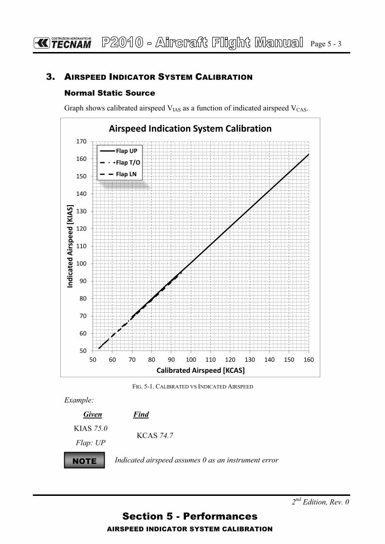
Page 5 - 3
Section 5 - Performances
AIRSPEED INDICATOR SYSTEM CALIBRATION
2nd Edition, Rev. 0
3. AIRSPEED INDICATOR SYSTEM CALIBRATION
Normal Static Source
Graph shows calibrated airspeed VIAS as a function of indicated airspeed VCAS.
50
60
70
80
90
100
110
120
130
140
150
160
170
50 60 70 80 90 100 110 120 130 140 150 160
Ind
icat
ed
Air
spe
ed
[K
IAS]
Calibrated Airspeed [KCAS]
Airspeed Indication System Calibration
Flap UP
Flap T/O
Flap LN
FIG. 5-1. CALIBRATED VS INDICATED AIRSPEED
Example:
Given Find
KIAS 75.0
Flap: UP KCAS 74.7
Indicated airspeed assumes 0 as an instrument error NOTE

Page 5 - 4
Section 5 - Performances
AIRSPEED INDICATOR SYSTEM CALIBRATION
2nd Edition, Rev. 0
Alternate Static Source
Alternate Static Air Open Vents Open Vents and Hot Air Open
IAS [kn]
HP [ft]
IAS [kn]
HP [ft]
IAS [kn]
HP [ft]
Pressure Altitude [ft]
IAS [kn]
FLAP UP
1000
70 75 1020 72 1010 72 1020
90 95 1020 92 1030 93 1020
110 115 1030 113 1020 112 1020
135 140 1040 139 1030 137 1030
FLAP T/O
60 63 1020 63 1020 62 1010
70 75 1020 73 1020 72 1020
90 94 1020 92 1020 92 1020
FLAP LND
60 62 1020 61 1020 61 1020
70 72 1020 72 1020 71 1020
90 92 1020 91 1020 91 1020
FLAP UP
5000
70 72 5020 72 5020 71 5020
90 94 5030 93 5020 92 5020
110 114 5030 113 5020 112 5020
133 137 5040 136 5030 135 5020
FLAP T/O
60 62 5010 62 5020 61 5010
70 74 5020 73 5020 72 5020
90 93 5030 93 5020 93 5020
FLAP LND
60 63 5030 62 5020 61 5000
70 72 5020 72 5010 71 5010
90 92 5020 92 5020 91 5010
FLAP UP
8000
70 72 8020 72 8020 71 8020
90 93 8030 92 8020 92 8020
110 113 8030 112 8020 112 8020
128 131 8040 130 8030 130 8020
FLAP T/O
60 62 8010 62 8020 61 8010
70 73 8020 72 8020 72 8020
90 92 8030 92 8020 92 8020
FLAP LND
60 61 8020 61 8020 61 8000
70 72 8010 71 8010 71 8010
90 92 8010 91 8010 91 8010

Page 5 - 5
Section 5 - Performances
ICAO STANDARD ATMOSPHERE
2nd Edition, Rev. 0
4. ICAO STANDARD ATMOSPHERE
FIG. 5-2. ICAO CHART
Examples: Scope Given Find
Density Altitude: A: Pressure altitude = 1600ft B: Temperature = 20°C → C: Density Altitude = 2550ft
ISA Temperature: D: Pressure altitude = 1600ft → E: ISA Air Temperature = 12°C
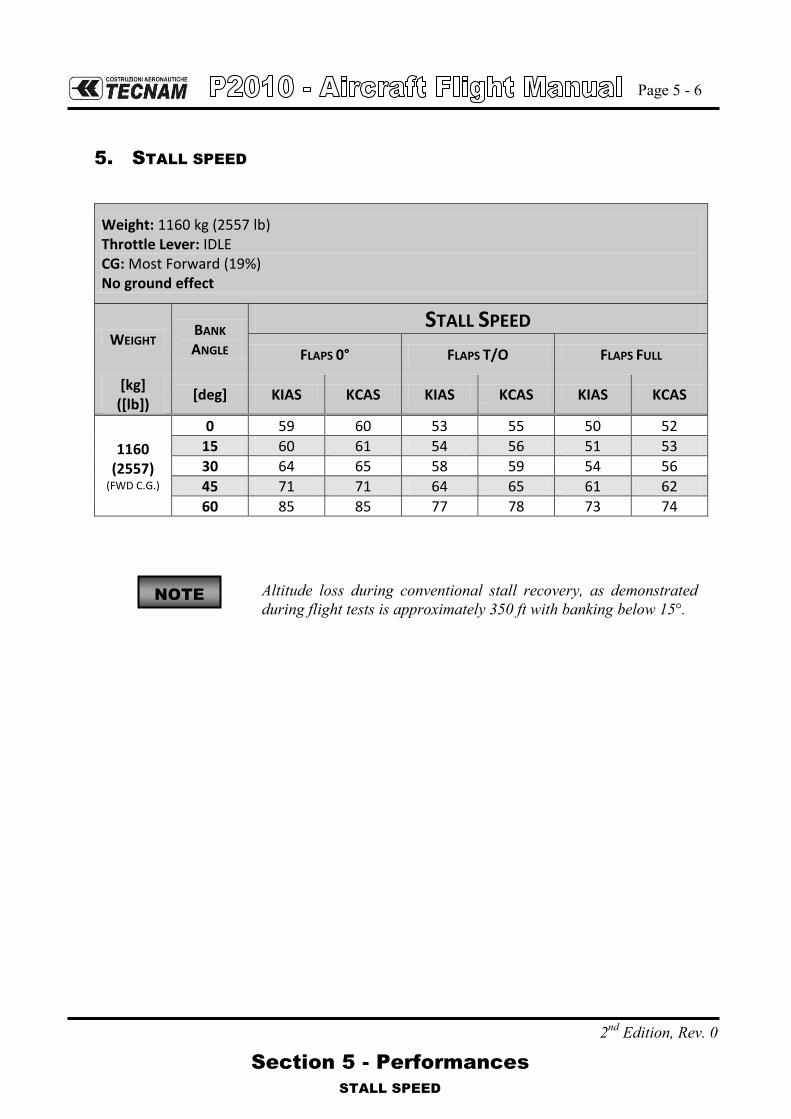
Page 5 - 6
Section 5 - Performances
STALL SPEED
2nd Edition, Rev. 0
5. STALL SPEED
Weight: 1160 kg (2557 lb) Throttle Lever: IDLE CG: Most Forward (19%) No ground effect
WEIGHT BANK ANGLE
STALL SPEED
FLAPS 0° FLAPS T/O FLAPS FULL
[kg] ([lb])
[deg] KIAS KCAS KIAS KCAS KIAS KCAS
1160 (2557)
(FWD C.G.)
0 59 60 53 55 50 52
15 60 61 54 56 51 53
30 64 65 58 59 54 56
45 71 71 64 65 61 62
60 85 85 77 78 73 74
Altitude loss during conventional stall recovery, as demonstrated during flight tests is approximately 350 ft with banking below 15°.
NOTE

Page 5 - 7
Section 5 - Performances
CROSSWIND
2nd Edition, Rev. 0
6. CROSSWIND
Maximum demonstrated crosswind is 12 kts.
Example:
Given Find
Wind direction (with respect to air-craft longitudinal axis) = 30°
Headwind = 17.5 kts
Wind speed = 20 kts Crosswind = 10 kts
FIG. 5-3. CROSSWIND CHART

Page 5 - 8
Section 5 - Performances
TAKE-OFF PERFORMANCES
2nd Edition, Rev. 0
7. TAKE-OFF PERFORMANCES
To account for likely in service performance variations apply a factored to distances of 1.10
Weight = 1160 kg (2557 lb) Flaps: T/O Speed at Lift-Off = 60 KIAS Speed Over 50ft Obstacle = 65 KIAS
Throttle Lever: Full Forward Runway: Paved Runway
Corrections
Headwind: - 10 m (33 ft) for each kn
Tailwind: +20 m (66 ft) for each kn
Grass Runway: + 10% to Ground Roll
Runway slope: +10% to Ground Roll for each +1%
Pressure Altitude
Distance [m]
(Distance [ft]) Temperature [°C]
ISA [ft] -25 0 25 50
S.L. Ground Roll
291 (955)
366 (1201)
451 (1480)
548 (1798)
416 (1365)
At 50 ft AGL 442
(1450) 552
(1811) 678
(2224) 818
(2684) 626
(2054)
1000 Ground Roll
317 (1040)
399 (1309)
492 (1614)
597 (1959)
446 (1463)
At 50 ft AGL 481
(1578) 601
(1972) 737
(2418) 890
(2920) 670
(2198)
2000 Ground Roll
346 (1135)
436 (1430)
538 (1765)
652 (2139)
479 (1572)
At 50 ft AGL 523
(1716 ft) 655
(2149 ft) 803
(2635 ft) 969
(3179 ft) 718
(2356)
3000 Ground Roll
378 (1240)
476 (1562)
587 (1926)
712 (2336)
515 (1690)
At 50 ft AGL 570
(1870) 713
(2339) 875
(2871) 1056
(3465) 770
(2526)
4000 Ground Roll
413 (1355)
520 (1706)
642 (2106)
779 (2556)
553 (1814)
At 50 ft AGL 622
(2041) 778
(2552) 954
(3130) 1151
(3776) 825
(2707)
5000 Ground Roll
452 (1483)
569 (1867)
702 (2303)
851 (2792)
595 (1952)
At 50 ft AGL 678
(2224) 848
(2782) 1041
(3415) 1256
(4121) 886
(2907)
6000 Ground Roll
494 (1621)
622 (2041)
768 (2520)
932 (3058)
640 (2100)
At 50 ft AGL 740
(2428) 926
(3038) 1136
(3727) 1371
(4498) 951
(3120)
NOTE

Page 5 - 9
Section 5 - Performances
TAKE-OFF PERFORMANCES
2nd Edition, Rev. 0
Weight = 1060 kg (2337 lb) Flaps: T/O Speed at Lift-Off = 60 KIAS Speed Over 50ft Obstacle = 65 KIAS
Throttle Lever: Full Forward Runway: Paved Runway
Corrections
Headwind: - 10 m (33 ft) for each kn
Tailwind: + 20 m (66 ft) for each kn
Grass Runway: + 10% to Ground Roll
Runway slope: +10% to Ground Roll for each +1%
Pressure Altitude
Distance [m] (Distance [ft])
Temperature [°C]
ISA [ft] -25 0 25 50
S.L.
Ground Roll 234
(768) 295
(968) 364
(1194) 441
(1447) 335
(1099)
At 50 ft AGL 358
(1178) 448
(1470) 549
(1801) 663
(2175) 507
(1663)
1000
Ground Roll 255
(837) 321
(1053) 397
(1302) 481
(1578) 359
(1178)
At 50 ft AGL 389
(1276) 487
(1598) 598
(1962) 721
(2365) 543
(1781)
2000
Ground Roll 279
(915) 351
(1152) 433
(1421) 525
(1722) 386
(1266)
At 50 ft AGL 424
(1391) 530
(1739) 651
(2136) 785
(2575) 582
(1909)
3000
Ground Roll 304
(997) 383
(1257) 473
(1552) 574
(1883) 414
(1358)
At 50 ft AGL 462
(1516) 578
(1896) 709
(2326) 856
(2808) 624
(2047)
4000
Ground Roll 333
(1092) 419
(1375) 517
(1696) 627
(2057) 445
(1460)
At 50 ft AGL 504
(1654) 630
(2067) 773
(2536) 933
(3061) 669
(2195)
5000
Ground Roll 364
(1194) 458
(1503) 565
(1854) 686
(2251) 479
(1572)
At 50 ft AGL 549
(1801) 687
(2254) 843
(2766) 1018
(3340) 718
(2356)
6000
Ground Roll 398
(1306) 501
(1644) 619
(2031) 750
(2461) 515
(1690)
At 50 ft AGL 600
(1968) 750
(2461) 921
(3022) 1111
(3645) 770
(2526)

Page 5 - 10
Section 5 - Performances
TAKE-OFF PERFORMANCES
2nd Edition, Rev. 0
Weight = 960 kg (2116 lb) Flaps: T/O Speed at Lift-Off = 60 KIAS Speed Over 50ft Obstacle = 65 KIAS
Throttle Lever: Full Forward Runway: Paved Runway
Corrections
Headwind: - 10 m (33 ft) for each kn
Tailwind: + 20 m (66 ft) for each kn
Grass Runway: + 10% to Ground Roll
Runway slope: +10% to Ground Roll for each +1%
Pressure Altitude
Distance [m] (Distance [ft])
Temperature [°C]
ISA [ft] -25 0 25 50
S.L.
Ground Roll 185
(607) 232
(761) 287
(942) 348
(1142) 264
(866)
At 50 ft AGL 284
(932) 355
(1165) 436
(1430) 526
(1726) 402
(1319)
1000
Ground Roll 201
(659) 253
(830) 313
(1027) 379
(1243) 283
(928)
At 50 ft AGL 309
(1014) 387
(1270) 474
(1555) 572
(1877) 431
(1414)
2000
Ground Roll 220
(722) 277
(909) 341
(1119) 414
(1358) 304
(997)
At 50 ft AGL 337
(1106) 421
(1381) 516
(1693) 623
(2044) 462
(1516)
3000
Ground Roll 240
(787) 302
(991) 373
(1224) 452
(1483) 327
(1073)
At 50 ft AGL 367
(1204) 459
(1506) 563
(1847) 679
(2228) 495
(1624)
4000
Ground Roll 262
(860) 330
(1083) 407
(1335) 494
(1621) 351
(1152)
At 50 ft AGL 400
(1312) 500
(1640) 613
(2011) 740
(2428) 531
(1742)
5000
Ground Roll 287
(942) 361
(1184) 446
(1463) 541
(1775) 378
(1240)
At 50 ft AGL 436
(1430) 546
(1791) 669
(2195) 807
(2648) 570
(1870)
6000
Ground Roll 314
(1030) 395
(1296) 488
(1601) 592
(1942) 406
(1332)
At 50 ft AGL 476
(1562) 595
(1952) 730
(2395) 881
(2890) 611
(2005)

Page 5 - 11
Section 5 - Performances
TAKE-OFF RATE OF CLIMB
2nd Edition, Rev. 0
8. TAKE-OFF RATE OF CLIMB
To account for likely in service performance variations apply a factored to rate of climb of 0.90
Throttle Lever: Full Forward Flaps: Take-Off
Weight Pressure Altitude
Climb Speed
Vy
Rate of Climb [ft/min]
Temperature [°C]
ISA [kg]
([lb]) [ft] [KIAS] -25 0 25 50
1160 (2557)
S.L. 72 1008 816 644 490 711
2000 72 862 673 504 352 596
4000 72 716 531 365 216 482
6000 72 571 389 226 79 368
8000 72 427 247 87 -57 253
10000 72 283 107 -51 -192 139
12000 72 139 -34 -188 -327 25
14000 72 -4 -174 -325 -462 -90
1060 (2337)
S.L. 72 1162 956 772 606 843
2000 72 1005 803 622 459 721
4000 72 849 650 472 312 598
6000 72 694 498 323 166 476
8000 72 539 346 175 20 353
10000 72 384 195 27 -125 230
12000 72 230 45 -121 -270 108
14000 72 77 -105 -268 -414 -15
960 (2116)
S.L. 71 1343 1120 920 741 997
2000 71 1173 954 758 581 865
4000 71 1004 788 596 422 732
6000 71 835 623 434 263 599
8000 71 667 459 273 105 466
10000 71 500 295 113 -52 333
12000 72 333 132 -47 -209 200
14000 72 166 -31 -207 -365 67
NOTE

Page 5 - 12
Section 5 - Performances
EN-ROUTE RATE OF CLIMB
2nd Edition, Rev. 0
9. EN-ROUTE RATE OF CLIMB
To account for likely in service performance variations apply a factored to rate of climb of 0.90
Throttle Lever: Full Forward Flaps: UP
Weight Pressure Altitude
Climb Speed
VY
Rate of Climb [ft/min]
Temperature [°C]
ISA [kg]
([lb]) [ft] [KIAS] -25 0 25 50
1160 (2557)
S.L. 82 1070 885 720 571 784
2000 82 929 747 585 439 674
4000 82 789 610 451 307 564
6000 82 649 474 317 176 454
8000 82 510 338 184 45 344
10000 82 372 202 51 -85 234
12000 82 233 67 -82 -215 123
14000 82 95 -68 -213 -345 13
1060 (2337)
S.L. 81 1222 1023 846 686 914
2000 81 1071 875 701 544 796
4000 81 920 728 557 402 678
6000 81 770 581 413 261 560
8000 81 620 435 270 120 441
10000 81 471 289 127 -20 323
12000 81 323 144 -16 -159 205
14000 81 175 -1 -157 -299 86
960 (2116)
S.L. 81 1400 1184 992 818 1066
2000 81 1236 1024 835 664 938
4000 81 1073 864 678 510 810
6000 81 910 705 522 357 681
8000 81 747 546 366 204 553
10000 80 585 388 211 52 424
12000 80 424 230 57 -99 296
14000 80 263 73 -97 -250 168
NOTE

Page 5 - 13
Section 5 - Performances
CRUISE PERFORMANCE
2nd Edition, Rev. 0
10. CRUISE PERFORMANCE
Weight = 1160 kg (2557 lb)
CORRECTIONS
KTAS Fuel
Consumption Endurance Range
Specific Range
For each +15 °C of OAT -2% -2.5% +2% +1% +1%
For each -15 °C of OAT +1% +3% -4% -2% -1%
For -100 kg (-220 lb) of weight +3.3% - - +3% +4%
CRUISE PERFORMANCE
Pressure Altitude
ft
OAT ISA
deg C RPM KTAS
Fuel Consumption
gal/hr (l/hr)
Endurance hr:mm
Range nm
Specific Range nm/gal (nm/l)
0 15 2700 137 16.6 (62.7) 3:40 502 8.3 (2.2)
2600 131 15.3 (57.8) 3:59 521 8.6 (2.3)
2500 125 14.1 (53.4) 4:18 538 8.8 (2.3)
2400 119 13.1 (49.4) 4:39 553 9.1 (2.4)
2200 107 11.3 (42.8) 5:22 573 9.4 (2.5)
2000 11 2700 136 15.9 (60.1) 3:50 521 8.6 (2.3)
2600 130 14.7 (55.6) 4:08 538 8.9 (2.3)
2500 124 13.6 (51.5) 4:28 554 9.1 (2.4)
2400 118 12.6 (47.9) 4:48 567 9.3 (2.5)
2200 106 11.0 (41.8) 5:30 583 9.6 (2.5)
4000 7 2700 135 15.2 (57.7) 3:59 540 8.9 (2.3)
2600 129 14.1 (53.5) 4:18 556 9.1 (2.4)
2500 123 13.1 (49.8) 4:37 570 9.4 (2.5)
2400 117 12.3 (46.4) 4:57 581 9.6 (2.5)
2200 105 10.8 (40.9) 5:37 592 9.7 (2.6)

Page 5 - 14
Section 5 - Performances
CRUISE PERFORMANCE
2nd Edition, Rev. 0
Weight = 1160 kg (2557 lb)
CORRECTIONS
KTAS Fuel
Consumption Endurance Range
Specific Range
For each +15 °C of OAT -2% -2.5% +2% +1% +1%
For each -15 °C of OAT +1% +3% -4% -2% -1%
For -100 kg (-220 lb) of weight +3.3% - - +3% +4%
CRUISE PERFORMANCE
Pressure Altitude
ft
OAT ISA
deg C RPM KTAS
Fuel Consumption
gal/hr (l/hr)
Endurance hr:mm
Range nm
Specific Range nm/gal (nm/l)
6000 3 2600 128 13.6 (51.6) 4:27 573 9.4 (2.5)
2500 122 12.7 (48.2) 4:47 585 9.6 (2.5)
2400 116 11.9 (45.1) 5:06 594 9.8 (2.6)
2200 104 10.6 (40.1) 5:44 598 9.8 (2.6)
8000 -1 2600 128 13.2 (49.9) 4:37 588 9.7 (2.6)
2500 122 12.3 (46.7) 4:55 598 9.8 (2.6)
2400 116 11.6 (44.0) 5:14 605 9.9 (2.6)
2200 104 10.4 (39.5) 5:49 603 9.9 (2.6)
10000 -5 2600 127 12.8 (48.3) 4:46 603 9.9 (2.6)
2500 121 12.0 (45.5) 5:04 610 10.0 (2.7)
2400 115 11.4 (43.0) 5:21 614 10.1 (2.7)
2200 103 10.3 (39.0) 5:54 606 10.0 (2.6)
12000 -9 2500 120 11.7 (44.4) 5:11 621 10.2 (2.7)
2400 114 11.1 (42.1) 5:28 621 10.2 (2.7)
2200 102 10.2 (38.5) 5:59 608 10.0 (2.6)

Page 5 - 15
Section 5 - Performances
LANDING PERFORMANCES
2nd Edition, Rev. 0
11. LANDING PERFORMANCES
To account for likely in service performance variations apply a factored to distances of 1.67
Weight = 1160 kg (2557 lb) Flaps: LAND Short Final Approach Speed = 66 KIAS
Throttle Lever: Idle Runway: Paved
Corrections
Headwind: - 4 m (-13 ft) for each kn
Tailwind: + 13 m(+43 ft) for each kn
Grass Runway: +10% to Ground Roll Runway slope: - 3% to Ground Roll for each +1%
Pressure Altitude
Distance [m] (Distance [ft])
Temperature [°C]
ISA [ft] -25 0 25 50
S.L. Ground Roll
204 (669)
225 (738)
245 (804)
266 (873)
237 (778)
At 50 ft AGL 488
(1601) 509
(1670) 529
(1736) 550
(1804) 521
(1709)
1000 Ground Roll
212 (696)
233 (764)
254 (833)
276 (906)
244 (801)
At 50 ft AGL 496
(1627) 517
(1696) 538
(1765) 560
(1837) 528
(1732)
2000 Ground Roll
220 (722)
242 (794)
264 (866)
286 (938)
251 (823)
At 50 ft AGL 504
(1654) 526
(1726) 548
(1798) 570
(1870) 535
(1755)
3000 Ground Roll
228 (748)
251 (823)
274 (899)
297 (974)
259 (850)
At 50 ft AGL 512
(1680) 535
(1755) 558
(1831) 581
(1906) 543
(1781)
4000 Ground Roll
236 (774)
260 (853)
284 (932)
308 (1010)
267 (876)
At 50 ft AGL 520
(1706) 544
(1785) 568
(1864) 592
(1942) 551
(1808)
5000 Ground Roll
245 (804)
270 (886)
295 (968)
320 (1050)
275 (902)
At 50 ft AGL 529
(1736) 554
(1818) 579
(1900) 604
(1982) 559
(1834)
6000 Ground Roll
255 (837)
280 (919)
306 (1004)
332 (1089)
284 (932)
At 50 ft AGL 539
(1768) 564
(1850) 590
(1936) 616
(2021) 568
(1864)
NOTE

Page 5 - 16
Section 5 - Performances
BALKED LANDING PERFORMANCE
2nd Edition, Rev. 0
12. BALKED LANDING PERFORMANCE
To account for likely in service performance variations apply a factored to rate of climb and to angle of climb of 0.90
Throttle Lever: Full Forward Flaps: LAND Speed: 67 KIAS
Weight Pressure Altitude
Steady Gradient of Climb [%]
Temperature [°C]
ISA [kg]
([lb]) [ft] -25 0 25 50
1160 (2557)
S.L. 11.5 8.6 6 3.6 7
1000 10.4 7.5 4.9 2.6 6.1
2000 9.3 6.4 3.9 1.6 5.3
3000 8.2 5.3 2.8 0.5 4.4
4000 7.1 4.3 1.8 -0.5 3.5
5000 6 3.2 0.7 -1.5 2.7
6000 4.9 2.1 -0.3 -2.6 1.8
7000 3.8 1.1 -1.4 -3.6 0.9
1060 (2337)
S.L. 13.6 10.4 7.6 5 8.7
1000 12.4 9.2 6.4 3.9 7.7
2000 11.2 8 5.3 2.7 6.8
3000 10 6.9 4.1 1.6 5.8
4000 8.8 5.7 2.9 0.5 4.9
5000 7.6 4.5 1.8 -0.7 3.9
6000 6.4 3.3 0.6 -1.8 3
7000 5.2 2.2 -0.5 -2.9 2
960 (2116)
S.L. 16 12.5 9.4 6.6 10.6
1000 14.7 11.2 8.1 5.3 9.6
2000 13.4 9.9 6.8 4 8.5
3000 12 8.6 5.6 2.8 7.5
4000 10.7 7.3 4.3 1.5 6.4
5000 9.4 6 3 0.3 5.4
6000 8.1 4.7 1.7 -1 4.3
7000 6.7 3.4 0.5 -2.2 3.3
NOTE

Page 5 - 17
Section 5 - Performances
NOISE DATA
2nd Edition, Rev. 0
13. NOISE DATA
Noise level, determined in accordance with ICAO/Annex 16 6th Ed., July 2011, Vol. I°, Chapter 10 and 14 CFR Part 36, is 77.576 dB(A).
NOTE: No determination has been made by the Federal Aviation Administration that the noise levels of this aircraft are or should be acceptable or unacceptable for operation at, into, or out of, any airport.

Page 5 - 18
Section 5 - Performances
2nd Edition, Rev. 0
INTENTIONALLY LEFT BLANK

Page 6 - 1
Section 6 – Weight and Balance
INDEX
2nd Edition, Rev. 0
SECTION 6 – WEIGHT AND BALANCE
INDEX
1. INTRODUCTION ............................................................................ 3
2. WEIGHING PROCEDURES ............................................................. 4
2.1. Preparation ................................................................................ 4
2.2. Levelling .................................................................................... 4
2.3. Weighing .................................................................................... 4
2.4. Determination of C.G. location ................................................. 4
2.5. Weighing record......................................................................... 5
2.6. Weighing record (II) ................................................................... 6
3. WEIGHTS AND C.G. ....................................................................... 7
3.1. C.G. CALCULATION SAMPLES ................................................... 8
3.1.1. FULL FUEL .............................................................................. 8
3.1.2. FULL PAYLOAD ....................................................................... 8
4. BAGGAGE LOADING ..................................................................... 9
5. EQUIPMENT LIST ........................................................................ 11

Page 6 - 2
Section 6 – Weight and Balance
2nd Edition, Rev. 0
INTENTIONALLY LEFT BLANK

Page 6 - 3
Section 6 – Weight and Balance
INTRODUCTION
2nd Edition, Rev. 0
1. INTRODUCTION
This section describes the procedure for establishing the basic empty weight and the moment of the aircraft. Loading procedure information is also provided.
Aircraft must be operated in accordance with the limits con-cerning the maximum takeoff weight and CG excursion as re-ported in Flight Manual Section 2.
Pilot is responsible for checking the weight and CG excursion are compliant with the related limits. CG excursion and weight limits are reported in Section 2 – Lim-itations.
NOTE

Page 6 - 4
Section 6 – Weight and Balance
WEIGHING PROCEDURES
2nd Edition, Rev. 0
2. WEIGHING PROCEDURES
2.1. PREPARATION
- Carry out weighing procedure inside closed hangar - Remove from cabin any object unintentionally left - Make sure Flight Manual and mandatory documents are on board - Align nose wheel - Drain fuel via the specific drain valve - Oil and hydraulic fluid at the operating levels - Move sliding seats to most forward position - Raise flaps to fully retracted position - Place control surfaces in neutral position - Place scales (min. capacity 300 kg (661.4 lb)) under each wheel
2.2. LEVELLING
- Level the aircraft (the reference for longitudinal levelling is made putting a spirit-level on the cabin floor as shown in the Aircraft Maintenance Manual).
- Adjust longitudinal attitude deflating nose tire
2.3. WEIGHING
- Record weight shown on each scale - Repeat weighing procedure three times - Calculate empty weight
2.4. DETERMINATION OF C.G. LOCATION
- Drop a plumb bob tangent to the wing leading edge and trace a reference mark on the floor (see Figure on Para. 2.5 or 2.6)
- Repeat the operation for other wing - Stretch a taught line between the two marks - Measure the distance between the reference line and both main and nose wheel
axis (A and B distances respectively) - Using recorded data it is possible to determine the aircraft C.G. location and the
aircraft moment (see following table)

Page 6 - 5
Section 6 – Weight and Balance
WEIGHING PROCEDURES
2nd Edition, Rev. 0
2.5. WEIGHING RECORD
Model P2010 S/N:________ Weighing no. ____ Date:_________
Datum: leading edge vertical
DATUM
B A
BALANCE NLG BALANCE LH/RH
kg or lbs meters or feet Nose wheel weight W1 = Plumb bob distance LH wheel AL = LH wheel weight WL = Plumb bob distance RH wheel AR = RH wheel weight WR = Average distance (AL+ AR)/2 A = W2 = WL+WR = Plumb bob distance from nose wheel B =
Empty weight We = W1 + W2 = [kg] or [lbs]
We
BWAWD )13()13( 12
[m] or [ft]
100378.1
% DD
Empty weight moment: M = (D .We) = [m . kg] or [ft . lbs]
Maximum takeoff weight WT = [kg] or [lbs] Empty weight We = [kg] or [lbs] Max. useful load WT - We Wu = [kg] or [lbs]
Signature
______________________

Page 6 - 6
Section 6 – Weight and Balance
WEIGHING PROCEDURES
2nd Edition, Rev. 0
2.6. WEIGHING RECORD (II)
Model P2010 S/N:________ Weighing no. ____ Date:_________
Datum: leading edge vertical
DATUM
B A
BALANCE NLG BALANCE LH/RH
kg or lbs meters or feet Nose wheel weight W1 = Plumb bob distance LH wheel AL = LH wheel weight WL = Plumb bob distance RH wheel AR = RH wheel weight WR = Average distance (AL+ AR)/2 A = W2 = WL+WR = Plumb bob distance from nose wheel B =
Empty weight We = W1 + W2 = [kg] or [lbs]
We
BWAWD )13()13( 12
[m] or [ft]
100378.1
% DD
Empty weight moment: M = (D .We) = [m . kg] or [ft . lbs]
Maximum takeoff weight WT = [kg] or [lbs] Empty weight We = [kg] or [lbs] Max. useful load WT - We Wu = [kg] or [lbs]
Signature
______________________

Page 6 - 7
Section 6 – Weight and Balance
WEIGHTS AND C.G.
2nd Edition, Rev. 0
3. WEIGHTS AND C.G.
C.G. position can be defined by means of the chart below.
The pilot is responsible for ensuring the correct useful load loading.
Figure 1
Example
A/C empty mass moment 188 kg*m (1360 lb*ft) A/C empty mass 765 kg (1687 lb) Occ. front seats 160 kg (353 lb) Occ. rear seats 140 kg (309 lb) Fuel 75 kg (165 lb) Baggage 20 kg (44 lb) A/C T.O. weight 1160 kg (2557 lb)
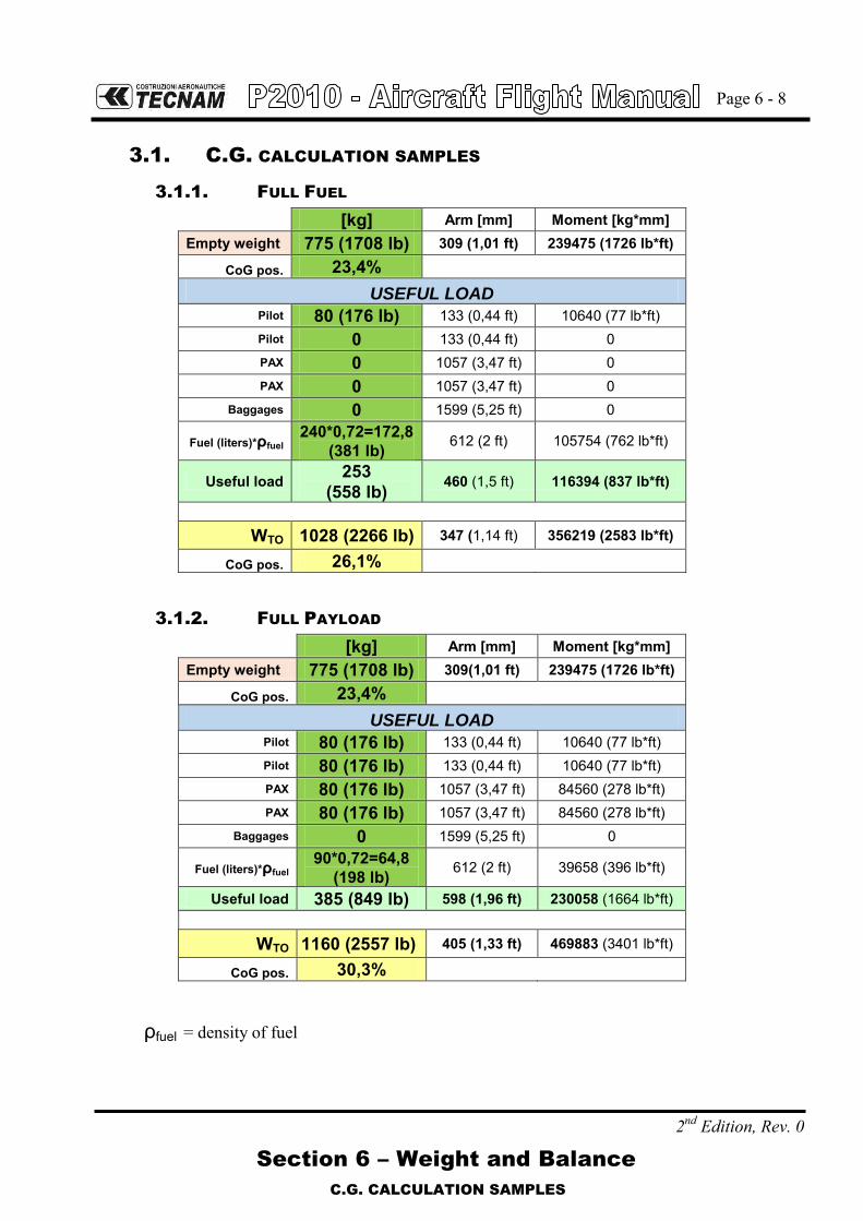
Page 6 - 8
Section 6 – Weight and Balance
C.G. CALCULATION SAMPLES
2nd Edition, Rev. 0
3.1. C.G. CALCULATION SAMPLES
3.1.1. FULL FUEL
[kg] Arm [mm] Moment [kg*mm]
Empty weight 775 (1708 lb) 309 (1,01 ft) 239475 (1726 lb*ft)
CoG pos. 23,4%
USEFUL LOAD Pilot 80 (176 lb) 133 (0,44 ft) 10640 (77 lb*ft) Pilot 0 133 (0,44 ft) 0 PAX 0 1057 (3,47 ft) 0 PAX 0 1057 (3,47 ft) 0
Baggages 0 1599 (5,25 ft) 0
Fuel (liters)*ρfuel 240*0,72=172,8
(381 lb) 612 (2 ft) 105754 (762 lb*ft)
Useful load 253 (558 lb) 460 (1,5 ft) 116394 (837 lb*ft)
WTO 1028 (2266 lb) 347 (1,14 ft) 356219 (2583 lb*ft)
CoG pos. 26,1%
3.1.2. FULL PAYLOAD
[kg] Arm [mm] Moment [kg*mm]
Empty weight 775 (1708 lb) 309(1,01 ft) 239475 (1726 lb*ft)
CoG pos. 23,4%
USEFUL LOAD Pilot 80 (176 lb) 133 (0,44 ft) 10640 (77 lb*ft) Pilot 80 (176 lb) 133 (0,44 ft) 10640 (77 lb*ft) PAX 80 (176 lb) 1057 (3,47 ft) 84560 (278 lb*ft) PAX 80 (176 lb) 1057 (3,47 ft) 84560 (278 lb*ft)
Baggages 0 1599 (5,25 ft) 0
Fuel (liters)*ρfuel 90*0,72=64,8
(198 lb) 612 (2 ft) 39658 (396 lb*ft)
Useful load 385 (849 lb) 598 (1,96 ft) 230058 (1664 lb*ft)
WTO 1160 (2557 lb) 405 (1,33 ft) 469883 (3401 lb*ft)
CoG pos. 30,3%
ρfuel = density of fuel

Page 6 - 9
Section 6 – Weight and Balance
BAGGAGE LOADING
2nd Edition, Rev. 0
4. BAGGAGE LOADING
The baggage loading in the dedicated compartment must be carried out in accord-ance with diagram addressed on PAR. 03 and with C.G. excursion and weight lim-itations reported in Section 2.
Pilot is provided with a red tie-down net and snap fasteners allowing for securing the loads on the compartment floor.
CAUTION
Loading the baggage, make sure that you correctly stretched the net which must be secured to the four vertices of the floor.

Page 6 - 10
Section 6 – Weight and Balance
2nd Edition, Rev. 0
INTENTIONALLY LEFT BLANK

Page 6 - 11
Section 6 – Weight and Balance
EQUIPMENT LIST
2nd Edition, Rev. 0
5. EQUIPMENT LIST
The following is a list of equipment which may be installed in the P2010. The items marked with an "X" were installed on the airplane described at the be-ginning of the list and they are included in the Basic Empty Weight. It is the owner’s responsibility to retain this equipment list and amend it to reflect changes in equipment installed in this airplane.

Page 6 - 12
Section 6 – Weight and Balance
EQUIPMENT LIST
2nd Edition, Rev. 0
EQUIPMENT LIST AIRCRAFT S/N_____ DATE:
REF. DESCRIPTION P/N INST
WEIGHT
[kg]
([lb])
ARM
[m]
([ft])
INSTRUMENTATION
A1 GARMIN G1000 IFDS
A2 MD 302 MID Continent 6420302-1 0.73 (1.61)
-0.69 (-2.26)
A3 Compass C2400L4P 0.4 (0.88)
-0.69 (-2.26)
A4 Pitch trim indicator – UMA instruments N0911S0U2DR00W 0.1 (0.22)
-0.69 (-2.26)
A5 Digital Clock - Davtron M800-28V-BAT 0.1 (0.22)
-0.69 (-2.26)
AVIONICS & MISCELLANEOUS
B1 ELT-ACK E-04 0.73 (1.61)
1.61 (5.28)
B2 Front seats GEVEN E5-01-007-T01 (LH) E5-01-008-T01 (RH)
10x2 = 20
(22x2 = 44) 0.50
(1.64)
B3 Rear seats GEVEN E5-01-007-T01 (LH) E5-01-008-T01 (RH)
10x2 = 20
(22x2 = 44) 1.26
(4.13)
B4 Fire extinguisher 13-07655 0.8 (1.76)
-0.18 (-0.59)
B5 First aid kit FIA270160 0.2 (0.44)
0.5 (1.64)
B6 Torch --------- 1
(2.2) -0.18
(-0.59)
B7 Battery GILL247- 24V -19Ah G247 19.3
(42.5) 3.05
(10.01)
B8 Fuel qty sender – Electronics international P-300C 0.15 (0.33)
0.5 (1.64)
B9 ADF Receiver – RA 3502 0505.757-912 1.5 (3.3)
3.05 (10.01)
B10 DME Transceiver - King KN 63 066-01070-0001 2 (4.4)
3.05 (10.01)
LIGHTS:
B11 Nav/POS/Strobe Light SH wing - Ultragalactica Aveo AVE-WPST R/G-54G 1 (2.2)
0.23 (0.75)
B12 Rudder Nav Light – PosiStrobe CT AVE-POSW-62G 1 (2.2)
5.5 (18.04)
B13 Landing/Taxy Light - WHELEN Mod 7167400 01-0771674-00 2 (4.4)
-1.52 (-4.99)
PITOT STATIC:
B14 Pitot (Heated) - Falcon Gauge 24-AN5812-1 3 (6.6)
0.5 (1.64)
LANDING GEAR ACCESSORIES
C1 Nose Landing Gear Wheel Fairing 210-4-3001-401 1.2 (2.6)
-1.48 (-4.86)
C2 Main Landing Gear Wheel Fairings 210-4-1020-001-L/R 1.5x2 = 3 (3.3x2 = 6.6)
0.66 (2.17)

Page 7 - 1
Section 7 – Airframe and Systems description
INDEX
2nd Edition, Rev. 0
SECTION 7 – AIRFRAME AND SYSTEMS DESCRIPTION
INDEX
1. INTRODUCTION ........................................................................... 2
2. AIRFRAME .................................................................................... 2
2.1. Wing ............................................................................................................. 2
2.2. Fuselage ...................................................................................................... 3
2.3. Empennages ................................................................................................ 3
2.3.1. Horizontal Tail ............................................................................................. 3
2.3.1. Rudder Surface ............................................................................................ 4
2.4. Main Landing gear ....................................................................................... 5
2.5. Nose landing gear ........................................................................................ 7
3. FLIGHT CONTROLS ..................................................................... 8
4. INSTRUMENT PANEL .................................................................. 9
4.1. Engine control lever .................................................................................. 10
4.2. Alternate Air .............................................................................................. 11
4.3. Defrost and Cabin Heat ............................................................................. 11
5. SEATS AND SAFETY HARNESS ................................................ 13
6. DOORS ....................................................................................... 14
7. POWERPLANT ............................................................................ 16
7.1. ENGINE ...................................................................................................... 16
7.2. PROPELLER ............................................................................................... 16
8. FUEL SYSTEM ............................................................................ 18
9. ELECTRICAL SYSTEM ............................................................... 20
9.1. Stall Warning System ................................................................................ 21
9.2. Avionics ..................................................................................................... 22
9.3. External Power Supply .............................................................................. 23
10. PITOT-STATIC PRESSURE SYSTEMS ....................................... 24
11. LIGHTS ....................................................................................... 26
11.1. External lights ........................................................................................... 26
11.2. Internal lights ............................................................................................ 27
12. PLACARDS ................................................................................. 28
12.1. External Placards ...................................................................................... 28
12.2. Internal Placards ....................................................................................... 32

Page 7 - 2
Section 7 – Airframe and Systems description
AIRFRAME
2nd Edition, Rev. 0
1. INTRODUCTION
This section provides description and operation of the aircraft and its systems.
2. AIRFRAME
P2010’s airframe can be divided in the following main groups, as highlighted below on fig-ure 7-1:
1) Wing 2) Fuselage 3) Empennage 4) Landing gear
Fig. 7-1. P2010 AIRFRAME
2.1. WING
Each wing is connected to the fuselage by means of two bolt attachments and a single strut brace per side. The wings are made up of a central light alloy torsion box; a light alloy lead-ing edge is attached to the front spar whereas the flap (“slotted”) and the aileron (“frise”) are attached to a rear spar through two hinges each. The torsion box consists of a front and rear spar that represent its front and rear vertical walls; a series of ribs and wrap-around panels complete the structure. Front and rear spars are integrated with wing-fuselage attachment fittings. Integral fuel tanks are located in the wing box, behind the main spar, with a capacity of 120 litres each (31,7 gallons). The ailerons and flaps are made by an aluminium spar attached to a formed sheet metal leading edge and metal ribs; an aluminium skin surrounds the aileron structure.
1 3
2
4

Page 7 - 3
Section 7 – Airframe and Systems description
AIRFRAME
2nd Edition, Rev. 0
2.2. FUSELAGE
The P2010 fuselage is mainly made by carbon fibres composite materials. The fuselage is made by two main shells that are later assembled bonding the two main bod-ies and the floor (composite) and adding aluminium parts that allow the connection of the main landing gear, seats, wing and instrument panel. Fuselage and vertical fin are thus a unique body.
2.3. EMPENNAGES
2.3.1. HORIZONTAL TAIL
The horizontal tail is an all-moving type; the stabilizer and elevator form a single uniform plane called stabilator that rotates to the desired pitch setting. The stabilator structure (see Figure 7-2) is made-up by two aluminium spar and ribs. Aluminium skin panels are riveted to the above elements. A trim tab provides stick force adjustment and longitudinal compensation through a control wheel located between pilot and co-pilot seats.
Front Spar
Rib
Nose Rib
Rear Spar
Trim-Tab
Fig. 7-2.STABILATOR STRUCTURE

Page 7 - 4
Section 7 – Airframe and Systems description
AIRFRAME
2nd Edition, Rev. 0
2.3.1. RUDDER SURFACE
The rudder structure is made-up by a single aluminium spar (1) and ribs (2). Aluminium skin panels (3) are riveted to the above elements. It is connected to the fin through two hing-es; at the lower hinge a bellcrank (4) is connected for the movement transmission. A trim tab (5) provides stick force adjustment and lateral compensation through a rocker switch located between pilot and co-pilot seats.
Fig. 7-3. RUDDER STRUCTURE
1
3
2
4
5

Page 7 - 5
Section 7 – Airframe and Systems description
AIRFRAME
2nd Edition, Rev. 0
2.4. MAIN LANDING GEAR
The main landing gear consists of two steel leaf-springs positioned crossways to the fuse-lage.
Fig. 7-4. MAIN LANDING GEAR STRUCTURE
The steel leaf-springs are attached to the fuselage structure on composite beams. Wheels are cantilevered on gear struts and feature hydraulically actuated disc brakes con-trolled by toe. Main gear wheels install type 6.00-6 tires inflated at 36 psi (2.5 bar).
P2010 is provided with an independent hydraulically actuated brake system for each main wheel. A master cylinder is attached to each pilot’s rudder pedal. Hydraulic pressure, ap-plied via the master cylinders, enters the brake via lines connected to an inlet fitting on the caliper. A parking brake valve, mounted in correspondence of the cabin floor and operated by a knob on the cockpit central pedestal, intercepts the hydraulic lines, once pressurized by toe brakes, to hold the brake assemblies linings tightened round the main wheels brake discs. Brakes can be operated from either pilot’s and co-pilot’s pedals: a single vented oil reservoir feeds the pilot side master cylinders which are connected, via hoses, with the co-pilot’s side ones.

Page 7 - 6
Section 7 – Airframe and Systems description
AIRFRAME
2nd Edition, Rev. 0
Left wheel brake Right wheel brakeLeft wheel brake Right wheel brake
Fig. 7-5. RUDDER PEDALS AND BRAKE MASTER CYLINDERS (PILOT AND CO-PILOT SIDE)
Fig. 7-6. BRAKE SYSTEM SCHEMATIC
Master Cylinders

Page 7 - 7
Section 7 – Airframe and Systems description
AIRFRAME
2nd Edition, Rev. 0
2.5. NOSE LANDING GEAR
A Pivoting nose gear is attached to the firewall reinforcement plate. The shock absorber is fitted on the upper machined component and directly on the nose landing gear structure.
In Figure 10 is shown: 1) Hydraulic shock absorber 2) Firewall 3) Nose wheel (5.00-5 tire, inflated at 32 PSI (2.2 BAR))
Fig. 7-7. NOSE LANDING GEAR
1
2
3
Page 7 - 8
Section 7 – Airframe and Systems description
FLIGHT CONTROLS
2nd Edition, Rev. 0
3. FLIGHT CONTROLS
Aircraft flight controls are operated through conventional stick and rudder pedals. Longitu-dinal control acts through a system of push-rods and is equipped with a trim tab. a cable control circuit is confined within the cabin and it is connected to a pair of push-pull rod sys-tems positioned in each main wing which control ailerons differentially. Aileron trimming is carried out on ground through a small tab positioned on left aileron. Flaps are extended via an electric servo actuator controlled by a switch on the instrument panel. Flaps act in continuous mode; the indicator displays three markings related to 0°, takeoff (T/O) and landing (FULL) positions. A breaker positioned on the right side of the instrument panel protects the electric circuit. The control of the stabilator trim is operated by means of a control wheel, located between the two front seats that acts directly on the control cables. Stabilator trim position is displayed on a dedicated analogue indicator located on the LH ar-ea of the instrument panel. Rudder Trimming device for lateral control is provided by means of an electrical actuator controlled by a rocker switch located near the pitch trim wheel; the surface is connected to a potentiometer linked to a rudder trim indicator included in the Garmin G1000 EIS (Engine Indication System).

Page 7 - 9
Section 7 – Airframe and Systems description
INSTRUMENT PANEL
2nd Edition, Rev. 0
4. INSTRUMENT PANEL
The instrument panel is divided in three areas:
The left area holds Garmin G1000 PFD, a chronometer and the pitch trim indicator; The Central area holds the standby unit for PFI parameters, MD 302 suite, and the
ELT button. The right area holds Garmin G1000 MFD and breaker panel; The lower-LH portion of the instrument panel holds:
Ignition key; Master and Generator switches; Emergency fuel pump; Avionic Master switch;
The lower-Central portion of the instrument panel holds: Fuel selector valve. Flap Control
The lower-RH portion of the instrument panel holds: Pocket
Fig. 7-8. INSTRUMENT PANEL

Page 7 - 10
Section 7 – Airframe and Systems description
INSTRUMENT PANEL
2nd Edition, Rev. 0
4.1. ENGINE CONTROL LEVER
Engine handling is via three levers: Throttle, RPM lever, Mixture control lever. They’re situated on the center control; the use of “front/forward” and “rear/backward” is defined in relation to the direction of flight (longitudinal). Mixture control lever This lever (right hand lever with red handle) controls the fuel-air mixture, which is supplied to the engine. With the lever full forward, extra fuel is being supplied to the engine which at higher performance setting contributes to engine cooling. In cruise, the mixture should be made leaner in order to reach the appropriate fuel-air mixture. The leaning procedure is given in Chapter 4.
Lever forward (RICH) >> Mixture rich (in fuel) Lever to rear (LEAN) >>Mixture lean (in fuel)
To shut off the engine the mixture control lever is pulled to the rear stop: air without fuel is drawn into the cylinders that shuts down. Throttle This lever (left hand with large knob) is used to control manifold pressure (MAP). High manifold pressure means a large quantity of fuel-air mixture is being supplied to engine, while low manifold pressure means a lesser quantity of fuel-air mixture is be-ing supplied.

Page 7 - 11
Section 7 – Airframe and Systems description
INSTRUMENT PANEL
2nd Edition, Rev. 0
4.2. ALTERNATE AIR
Alternate Air knob is located on the central pedestal; when the knob is fully pulled outward from the instrument panel, injectors receive maximum hot air. During normal operation, the knob is set in OFF position.
4.3. DEFROST AND CABIN HEAT
Two knobs, located on the lower side of the central pedestal, allow Defrost and Cabin Heat function. The one marked as “Defrost and Cabin Heat” allows hot air to perform windshield defrost and partially cabin heat. The cabin heat control knob, when fully outward, allows cabin to receive maximum hot air. When both cabin heat and defrost and cabin heat are pulled, air is partitioned.
Fig. 7-9. CENTRAL PEDESTAL

Page 7 - 12
Section 7 – Airframe and Systems description
2nd Edition, Rev. 0
INTENTIONALLY LEFT BLANK

Page 7 - 13
Section 7 – Airframe and Systems description
SEATS AND SAFETY HARNESS
2nd Edition, Rev. 0
5. SEATS AND SAFETY HARNESS In correspondence of the seats, three fitting points safety belts are provided; belt ad-justment is via the sliding buckle located on the belt metal hook. Seats are built with light allow tube structure and synthetic material cushioning. It is
possible to perform following seat adjustments:
Horizontal – pulling the lower front lever and sliding the seat Vertical – operating the lever located on the outward seat side Seat back inclination – unlocking it via the lateral knob
These adjustments ensure the crew and passengers comfort.
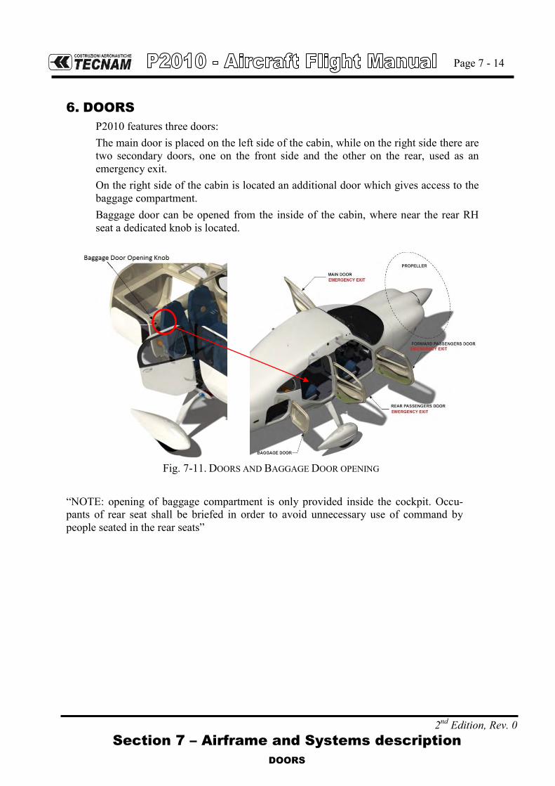
Page 7 - 14
Section 7 – Airframe and Systems description
DOORS
2nd Edition, Rev. 0
6. DOORS
P2010 features three doors: The main door is placed on the left side of the cabin, while on the right side there are two secondary doors, one on the front side and the other on the rear, used as an emergency exit. On the right side of the cabin is located an additional door which gives access to the baggage compartment. Baggage door can be opened from the inside of the cabin, where near the rear RH seat a dedicated knob is located.
Fig. 7-11. DOORS AND BAGGAGE DOOR OPENING
“NOTE: opening of baggage compartment is only provided inside the cockpit. Occu-pants of rear seat shall be briefed in order to avoid unnecessary use of command by people seated in the rear seats”

Page 7 - 15
Section 7 – Airframe and Systems description
DOORS
2nd Edition, Rev. 0
The internal handle can be locked, to avoid any chance of inadvertent opening, by means of a hook located nearby the handle itself and upper safety block, following pictures show the functioning.
Fig. 7-12. HANDLE LOCKING
In case of rapid escapes or door handles malfunction, an emergency opening is provided on the rear side of the door. The opening is operated by means of a hook, moved forward, that bypasses the normal door opening.
Fig. 7-13. EMERGENCY OPENING

Page 7 - 16
Section 7 – Airframe and Systems description
POWERPLANT
2nd Edition, Rev. 0
7. POWERPLANT
7.1. ENGINE
Manufacturer …………………………… Lycoming Textron Model …………………………………... IO-360-M1A Type Certificate ………………………... EASA TCDS no. IM.E.032 Engine type …………………………….. Fuel injected (IO), direct drive, four cylinder
horizontally opposed, air cooled with down exhaust outlets.
Maximum power ……. Maximum continuous power …………...
134.0 kW (180hp) @ 2700 rpm 134.0 kW (180hp) @ 2700 rpm
Oil Consumption Operation RPM HP Max.
Oil Cons. Qts./Hr.
*Max. Cyl. Head
Temp. Normal Rated 2700 180 .80 500°F (260°C) Performance Cruise (75%) 2450 135 .45 500°F (260°C) Economy Cruise (60R Rated) 2350 117 .39 500°F (260°C)
7.2. PROPELLER
Manufacturer ………………………….. MT Propeller Model …………………………………. MT 188 R 145 – 4G Type Certificate ……………………….. EASA TCDS no. P.006 Blades/hub …………………………….. 2 wood/composite blades – aluminium hub Diameter ………………………………. 1880 mm (6,17 ft) no reduction allowed Type …………………………………… Fixed pitch

2nd Edition, Rev 0
Section 7 – Airframe and Systems description
Page 7 - 17
INTENTIONALLY LEFT BLANK

Page 7 - 18
2nd Edition, Rev 0 Section 7 – Airframe and Systems description
FUEL SYSTEM
8. FUEL SYSTEM
The fuel system is designed to supply the reciprocating engine (Lycoming IO-360-M1A) with the suitable flow rate and pressure according to engine limitations required by Lycoming operator manual. Following figure shows a schematic of the fuel system assy for P2010 airplane.
OFF
RH
LH
LH Fuel qty indicator RH Fuel qty indicator
RH Fuel ventLH Fuel vent
LH Fuel tank RH Fuel tank
RH Fuel sumpLH Fuel sump
Firewall
Gascolator Electricfuel pump
Mechanicalfuel pump
Vent
VentInjector
Nozzle pressureconnection
Fuel pressuresensor
Fuel flowsensor
Fuel pressureindicator
Fuel flowindicator
Fig. 7-14. FUEL SYSTEM SCHEME
Each fuel tank is integrated within the wing box. The capacity of each tank is 120 liters (31,7 gal.), total capacity is thus 240 liters (63.4 gal.). The internal side of fuel tank is accessible for inspection through 4 upper dedicat-ed caps. Two bottom inspection panels allow the inspection of vent line and tank structure. An anti-sloshing movable wall is located within each fuel tank, this prevents fuel centrifugation which is a possible cause of undesired engine shut down. The fuel tank filler cap is located on the top of the wing, in the area outside of the tank and it is easily accessible from the leading edge of the aircraft. At the lowest point of the tank it is positioned a drain sump. The engine is equipped with an engine gear pumps, mechanical (primary). An ad-ditional auxiliary electrical fuel pump is provided (auxiliary). The fuel selector is operated by a fuel selector control knob located in the cabin on the central panel. The fuel selector control and the fuel valve are connected via a rigid control rod.

Page 7 - 19
2nd Edition, Rev 0 Section 7 – Airframe and Systems description
INTENTIONALLY LEFT BLANK

Page 7 - 20
2nd Edition, Rev 0 Section 7 – Airframe and Systems description
ELECTRICAL SYSTEM
9. ELECTRICAL SYSTEM
Primary DC power is provided by an external alternator with a 28 VDC output, rated of 70 Amps @ 2700 rpm. During normal operations, it recharges the battery. Secondary DC power is provided by a lead type battery (GILL G-247) which pro-vides the energy necessary for feeding the essential electrical loads in the event of an alternator failure. The switch between the energy sources is automatic and no action is required in order to activate the alternate energy source. For ground maintenance and/or starting, an external power socket is provided. The alternator and battery are connected to the battery bus in order to provide en-ergy for the electric equipment.
Each electrically fed instrument is connected to a dedicated circuit breaker which protects the cable from the battery bus to the associated electric equipment.
WARNING
If the Ignition is in the position L, R, or BOTH, an accidental movement of the propeller may start the engine with possible dan-ger for bystanders.
In the following figure is presented the electrical system architecture.

Page 7 - 21
2nd Edition, Rev 0 Section 7 – Airframe and Systems description
ELECTRICAL SYSTEM
FIG.7-15. ELECTRICAL SYSTEM ARCHITECTURE
9.1. STALL WARNING SYSTEM
The aircraft is equipped with a stall warning system consisting of a sensor located on the right wing leading edge connected to a warning horn located near the in-strument panel.

Page 7 - 22
2nd Edition, Rev 0 Section 7 – Airframe and Systems description
ELECTRICAL SYSTEM
9.2. AVIONICS
The avionic system installed on P2010 is mainly based on the integrated avionic suite Garmin G1000. The installed configuration is based on a two-screen layout. Primary flight information are displayed on the LH screen, namely PFD (Primary Flight Display). Primary Engine and moving map information are displayed on the RH display, namely MFD (Multi-Function Display). Both communication and navigation means, including the ones provided by third party units (i.e. ADF and DME), are integrated within the suite and their related information are displayed on both PFD and MFD. In the event of a PFD or MFD failure the “reversionary mode” is automatically enabled. In the event of a failure of the automatic reversion logic, the pilot can force rever-sionary mode by pressing “reversionary mode” button marked in red and located on the audio-panel. When reversionary mode is activated primary flight and engine information are presented together on the remaining display. In order to provide the pilot with main flight information in the event of a dual display failure of both PFD and MFD, or in the event of an AHRS and ADC units combined failure, an integrated digital stand-by instrument, Mid-Continent MD-302, featuring airspeed, altitude, attitude and slip information is installed. A dedicated analogue indicator is provided for pitch trim position. The installed equipment is such that the aircraft is able to fly under day/night VFR and day/night IFR rules and to perform ILS CAT I approaches with ILS.

Page 7 - 23
2nd Edition, Rev 0 Section 7 – Airframe and Systems description
ELECTRICAL SYSTEM
9.3. EXTERNAL POWER SUPPLY
On the right side of the tail cone, an external power is present. Using this device it is possible to feed the electric system directly on the main bus bar, by an external power source. It should be used at the engine start-up in cold weather condition. A white advisory “EXT. POWER” label will appear on Garmin PFD display upon connection of external power in order to advise pilot; the label will disappear up-on disconnection of ground external power.
CAUTION
Exercise caution while applying external power. Exercise extreme caution while disconnecting external power with engine running due to airflow coming from the propeller. Approach the power supply receptacle from rear of the wing. Make a positive check, upon disconnection, that: - the power chord is free from any aircraft structure - the receptacle is firmly closed.
Follow this procedure to start the engine using the external power source. 1. Ignition key, Master switch, Generator switch: OFF 2. Open the receptacle door and insert the external power source’s plug into the
socket 3. Engine start-up procedure (see Sect. 4 in this manual) 4. Disconnect the external power source’s plug and close firmly the receptacle
door.

Page 7 - 24
2nd Edition, Rev 0 Section 7 – Airframe and Systems description
PITOT-STATIC PRESSURE SYSTEMS
10. PITOT-STATIC PRESSURE SYSTEMS
The P2010 air speed/altitude indicating systems are connected with a Pitot-Static sys-tem based on a total pressure/Pitot probe (simple Pitot tube, heated for icing protec-tion) mounted on left wing strut and two static pressure ports connected in parallel and located in correspondence of engine firewall on left and right side of fuselage. Flexible hoses connects total pressure and static ports to primary analogue instru-ments, anemometer and altimeter. Garmin G1000 suite and standby MD 302 unit are connected to both static and total pressure lines providing both air speed and altitude information.
GARMIN G1000
LH STATIC PORT RH STATIC PORT
"T" JOINT
MD-302
ALTERNATE STATIC PORT
ALTERNATE STATIC PORT VALVE
GDC 74A
ADC
12
3
4
Pos. Description
1
2
3
4
Pitot
"T" Joint
Garmin G1000 connection
MD-302
0°
T/O
LND
FLAP
FIG.7-16. PITOT-STATIC SYSTEM
Legenda: Static line Total line

Page 7 - 25
2nd Edition, Rev 0 Section 7 – Airframe and Systems description
INTENTIONALLY LEFT BLANK
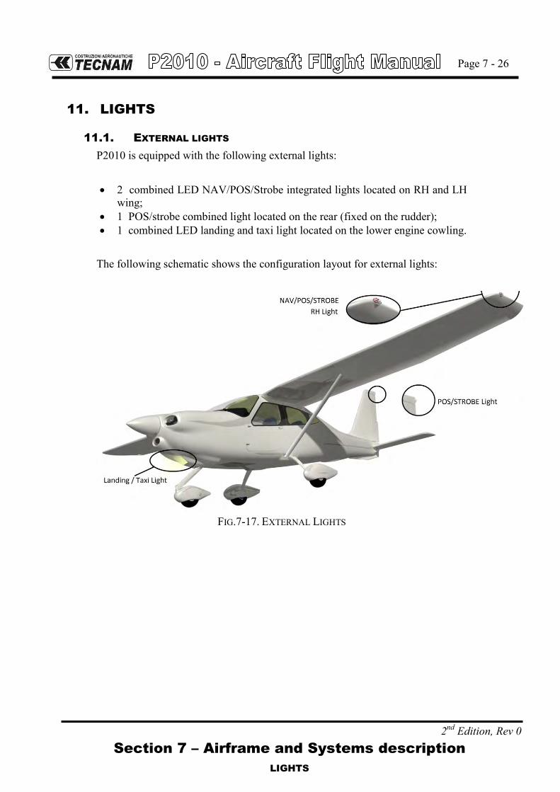
Page 7 - 26
2nd Edition, Rev 0 Section 7 – Airframe and Systems description
LIGHTS
11. LIGHTS
11.1. EXTERNAL LIGHTS
P2010 is equipped with the following external lights: 2 combined LED NAV/POS/Strobe integrated lights located on RH and LH
wing; 1 POS/strobe combined light located on the rear (fixed on the rudder); 1 combined LED landing and taxi light located on the lower engine cowling.
The following schematic shows the configuration layout for external lights:
FIG.7-17. EXTERNAL LIGHTS

Page 7 - 27
2nd Edition, Rev 0 Section 7 – Airframe and Systems description
LIGHTS
11.2. INTERNAL LIGHTS
On the cabin ceiling are located four map lights, two in the front area (pilot) and two in the rear area (passengers). In the central area of the cabin ceiling is located a spot light used to illuminate the pedestal during night flight operations. All ceiling lights are dimmable by a dedicat-ed dimmer.
FIG.7-18. CABIN CEILING LIGHTS LAYOUT
The instrument panel can be illuminated by 8 incandescence light strips, all dimma-ble.
FIG.7-19. INSTRUMENT PANEL LIGHTS LAYOUT
FWD
From mid MAP light (ceiling)

Page 7 - 28
2nd Edition, Rev 0 Section 7 – Airframe and Systems description
PLACARDS
12. PLACARDS
In addition to the limitation placards reported on Section 2, following placards are installed on the aircraft.
Additionally, nearby the placards listed below (English lan-guage), directly translated placards in the language of the country in which the airplane is registered can be installed, when required by the specific NAA.
12.1. EXTERNAL PLACARDS
Aircraft Registration Placard:
External Power Socket and baggage compartment placards:
NOTE

Page 7 - 29
2nd Edition, Rev 0 Section 7 – Airframe and Systems description
PLACARDS
Static Ports:
Lift Point:
Wheel Fairing “No Step”:

Page 7 - 30
2nd Edition, Rev 0 Section 7 – Airframe and Systems description
PLACARDS
Allowed Fuel Placard:
Tire Pressure placard:
Stabilator degrees placard:

Page 7 - 31
2nd Edition, Rev 0 Section 7 – Airframe and Systems description
PLACARDS
Emergency exit placards:

Page 7 - 32
2nd Edition, Rev 0 Section 7 – Airframe and Systems description
PLACARDS
12.2. INTERNAL PLACARDS
Safety equipment placards:

Page 7 - 33
2nd Edition, Rev 0 Section 7 – Airframe and Systems description
PLACARDS
ELT unit position placard:
Breaker Panel placards:

Page 7 - 34
2nd Edition, Rev 0 Section 7 – Airframe and Systems description
PLACARDS
Magnetic Compass placard:
Battery Placard:

Page 7 - 35
2nd Edition, Rev 0 Section 7 – Airframe and Systems description
PLACARDS
Oil Filler placard:
Emergency exit placards

Page 7 - 36
2nd Edition, Rev 0 Section 7 – Airframe and Systems description
PLACARDS
Pedestal placards:

Page 7 - 37
2nd Edition, Rev 0 Section 7 – Airframe and Systems description
PLACARDS
Fuel selector valve and Flap control knob:
Baggage Door opening knob:
Oil brake reservoir placard:
A – Oil brake reservoir placard B – Oil brake reservoir placard if MOD2010/020 is installed
A B

Page 7 - 38
2nd Edition, Rev 0 Section 7 – Airframe and Systems description
INTENTIONALLY LEFT BLANK

Section 8 – Aircraft Care and Maintenance
INDEX
Page 8 - 1
2nd Edition, Rev. 0
SECTION 8 – GROUND HANDLING & SERVICE
INDEX
1. Introduction ............................................................................. 3
2. Aircraft Inspection Intervals................................................... 5
3. Aircraft Changes or Repairs ................................................... 6
4. Maintenance ............................................................................ 7
4.1 Refuelling ................................................................................. 7
4.2 Engine and Brakes Oil level control ....................................... 7
4.3 Landing gear tires pressure control ....................................... 9
5. Engine Cowling Check .......................................................... 10
5.1 Upper cowling ....................................................................... 10
5.2 Lower Cowling ....................................................................... 10
6. Ground Handling .................................................................... 11
6.1 Towing ................................................................................... 11
6.2 Parking and Tie-Down ........................................................... 11
6.3 Mooring .................................................................................. 13
6.4 Jacking .................................................................................. 14
6.5 Road Transport ...................................................................... 14
7. Cleaning And Care ................................................................. 15
7.1 Windows ................................................................................. 15
7.2 External surfaces .................................................................. 15
7.3 Propeller ................................................................................ 15
7.4 Engine .................................................................................... 15
7.5 Internal surfaces ................................................................... 15
8. Ice removal ............................................................................ 16
Page 8 - 2
Section 8 – Aircraft Care and Maintenance
2nd Edition, Rev. 0
INTENTIONALLY LEFT BLANK

Page 8 - 3
Section 8 – GROUND HANDLING & SERVICE
INTRODUCTION
2nd Edition, Rev. 0
1. INTRODUCTION
This section contains factory-recommended procedures for proper ground han-dling and routine care and servicing. It also identifies certain inspection and maintenance requirements. It is recommended to follow a planned schedule of lubrication and preventive maintenance based on climatic and flying conditions encountered locally.

Page 8 - 4
Section 8 – GROUND HANDLING & SERVICE
2nd Edition, Rev. 0
INTENTIONALLY LEFT BLANK

Page 8 - 5
Section 8 – GROUND HANDLING & SERVICE
AIRCRAFT INSPECTION INTERVALS
2nd Edition, Rev. 0
2. AIRCRAFT INSPECTION INTERVALS
Scheduled inspections must be performed in accordance with the instructions addressed on the Aircraft Maintenance Manual. Independently from the aircraft flight hours, an annual inspection has to be performed. All required inspections are reported in the Aircraft Maintenance Manual. As far as the scheduled/unscheduled engine maintenance is concerned, refer to the engine manufacturer Maintenance Manual.
CAUTION
Unscheduled inspections/maintenance tasks are necessary when one or more of following conditions occur:
1. Emergency landing 2. Breaking / damage of propeller (or in case of
simple impact) 3. Engine fire 4. Lighting damage 5. Any type of damage or failure

Page 8 - 6
Section 8 – GROUND HANDLING & SERVICE
AIRCRAFT CHANGES OR REPAIRS
2nd Edition, Rev. 0
3. AIRCRAFT CHANGES OR REPAIRS
Aircraft changes or repairs must be performed in accordance with Aircraft Maintenance Manual and Job cards provided by TECNAM.

Page 8 - 7
Section 8 – GROUND HANDLING & SERVICE
MAINTENANCE
2nd Edition, Rev. 0
4. MAINTENANCE
4.1 REFUELLING
WARNING
- Do not perform aircraft refuelling near flames, sparks or similar. - Avoid fuel contact with the skin: a skin corrosion could occur. - Make sure that a fire extinguisher is available nearby during refu-
elling operations. - Make sure that overall aircraft instrumentation is turned OFF be-
fore performing the refuelling. - Do not operate switches and/or pushbuttons inside the aircraft dur-
ing refuelling operation; make sure that crew left the aircraft be-fore performing refuelling.
- Make sure that the aircraft is electrically connected to the ground.
4.2 ENGINE AND BRAKES OIL LEVEL CONTROL
1. Open the engine cowling (RH) 2. Clean the dipstick and soak it in the reservoir 3. Remove dipstick and read oil level 4. If required, replenish oil: oil level should be between max. and min.
Marks shown on the dipstick 5. Close the engine cowling 6. Repeat for LH engine cowling side for Oil brakes level control.
FIG. 8-1. OIL CHECK
RH Engine Cowling

Page 8 - 8
Section 8 – GROUND HANDLING & SERVICE
MAINTENANCE
2nd Edition, Rev. 0
FIG. 8-1 BIS OIL CHECK
A – Oil brake reservoir placard B – Oil brake reservoir placard if MOD2010/020 is installed
LH Engine Cowling
A B
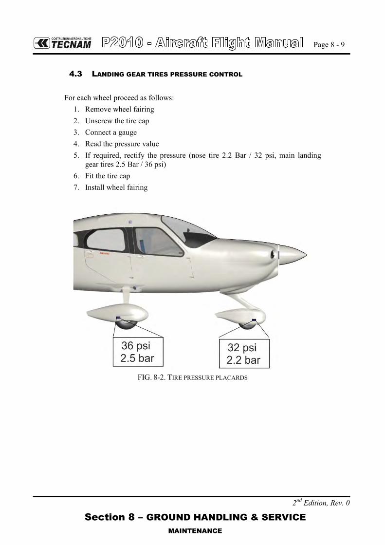
Page 8 - 9
Section 8 – GROUND HANDLING & SERVICE
MAINTENANCE
2nd Edition, Rev. 0
4.3 LANDING GEAR TIRES PRESSURE CONTROL
For each wheel proceed as follows:
1. Remove wheel fairing 2. Unscrew the tire cap 3. Connect a gauge 4. Read the pressure value 5. If required, rectify the pressure (nose tire 2.2 Bar / 32 psi, main landing
gear tires 2.5 Bar / 36 psi) 6. Fit the tire cap 7. Install wheel fairing
FIG. 8-2. TIRE PRESSURE PLACARDS

Page 8 - 10
Section 8 – GROUND HANDLING & SERVICE
ENGINE COWLING CHECK
2nd Edition, Rev. 0
5. ENGINE COWLING CHECK
5.1 UPPER COWLING
1. Parking brake: ON 2. Fuel selector valve: OFF 3. Ignition key: OFF 4. Generator & Master switches: OFF 5. Unlatch all four butterfly Cam-locks mounted on the cowling by rotat-
ing them 90° counter clockwise while slightly pushing inwards. 6. Remove engine cowling paying attention to propeller shaft passing
through nose. 7. To assemble: rest cowling horizontal insuring proper fitting of nose
base reference pins. 8. Secure latches by applying light pressure, check for proper assembly
and fasten Cam-locks.
WARNING
Butterfly Cam-locks are locked when tabs are horizontal and open when tabs are vertical. Verify tab is below latch upon closing.
5.2 LOWER COWLING
1. After disassembling upper cowling, move the propeller to a horizontal position.
2. Using a standard screwdriver, press and rotate 90° the two Cam-locks positioned on lower cowling by the firewall.
3. Disconnect the ram-air duct from the NACA intake. Pull out the first hinge pin positioned on the side of the firewall, then, while holding cowling, pull out second hinge pin; remove cowling with downward motion.
4. For installation follow reverse procedure.

Page 8 - 11
Section 8 – GROUND HANDLING & SERVICE
GROUND HANDLING
2nd Edition, Rev. 0
6. GROUND HANDLING
6.1 TOWING
The aircraft is most easily and safely maneuvered by hand by pushing on wing struts near attachments or by pulling it by its propeller near the axle. A tow bar can be fixed onto nose gear fork. Aircraft may be steered by turning rudder or, for steep turns, by pushing lightly on tail cone to lift nose wheel.
6.2 PARKING AND TIE-DOWN
General Under normal weather conditions, the airplane may be parked and headed in a di-rection that will facilitate servicing without regard to prevailing winds. Ensure that it is sufficiently protected against adverse weather conditions and present no danger to other aircraft. Procedure 1. Position airplane on levelled surface, headed into the prevailing wind, if prac-
tical. 2. Engage parking brake 3. Secure pilot control wheel by wrapping the seat belt around it
Do not engage the parking brakes at low ambient temperature, when an accumulation of moisture may cause the brakes to freeze, or when they become hot from severe use. In this case use wheel chocks.
In case of long time parking or overnight parking, it is recommended to moor the a/c as shown on Para.6.3.
CAUTION
Mooring is strongly recommended when the wind is more than 15 knots and the a/c is completely refuelled.

Page 8 - 12
Section 8 – GROUND HANDLING & SERVICE
2nd Edition, Rev. 0
INTENTIONALLY LEFT BLANK

Page 8 - 13
Section 8 – GROUND HANDLING & SERVICE
GROUND HANDLING
2nd Edition, Rev. 0
6.3 MOORING
The aircraft is moored to insure its immovability, protection, and security under various weather conditions.
CAUTION
Mooring is strongly recommended when the wind is more than 15 knots and the a/c is completely refuelled.
Procedure 1. Position airplane on levelled surface and headed into the prevailing wind, if
practical 2. Centre nose wheel and engage parking brake and/or use the wheel chocks
Do not engage the parking brakes at low ambient temperature, when an accumulation of moisture may cause the brakes to freeze, or when they become hot from severe use. In these cases use wheel chocks.
3. Secure pilot control stick by wrapping the seat belt around it 4. Assure that flaps are retracted 5. Electrically ground airplane, by connecting ground cable to the engine muffle 6. Install control locks 7. Install protective plugs 8. Close and lock cabin doors. 9. Secure tie-down cables to the nose gear leg (and to the wings (in correspond-
ence of wing struts) and tail cone tie-down rings at approximately 45 degree with respect to the ground.
Additional preparation for high winds includes tie-down ropes from the main landing gear employment.
z z
yx y
x
D
C
A
C
C
45°
45°
45°45°
45°

Page 8 - 14
Section 8 – GROUND HANDLING & SERVICE
GROUND HANDLING
2nd Edition, Rev. 0
6.4 JACKING
The aircraft can be lifted up by hydraulic jacks in correspondence of the points shown by external placards. For the correct procedure please refer to the Maintenance Manual.
6.5 ROAD TRANSPORT
It is recommended to secure tightly all aircraft components onto the cart to avoid damage during transport. Minimum cart size is 9x4 meters. It is suggested to place wings under the aircraft’s bottom, secured by specific clamps. Secondary components like the stabilator shall be protected from accidental hits using plas-tic or other material. For correct rigging and de-rigging procedure, refer to the Maintenance Manual.

Page 8 - 15
Section 8 – GROUND HANDLING & SERVICE
CLEANING AND CARE
2nd Edition, Rev. 0
7. CLEANING AND CARE
CAUTION
Aircraft surface must be kept clean to ensure expected flight per-formance. Excessively dirty surfaces can affect normal flight con-ditions.
7.1 WINDOWS
For windows cleaning, it is allowed the use of acrylic products employed for glass and Plexiglas surfaces cleaning.
7.2 EXTERNAL SURFACES
Aircraft surface is cleaned with soapy water; they are not allowed solvents or al-cohol based products. Died insects must be removed using hot water. It is advisable to avoid outside aircraft parking for long periods; it is always con-venient to keep the aircraft in the hangar.
7.3 PROPELLER
To preserve its functionality avoiding wear and corrosion, the propeller manufac-turer uses, for external surface painting, an acrylic paint which is resistant to all solvents. In any case it is advisable to clean the propeller using exclusively soapy water.
7.4 ENGINE
Engine cleaning is part of the scheduled maintenance. Refer to the engine manu-facturer Maintenance Manual for operating and for planning its cleaning.
7.5 INTERNAL SURFACES
Interiors must be cleaned with a rate of 3 to 6 months. Any object present in the cabin (like pens, lost property, maps etc) must be removed. The instrumentation as a whole must be cleaned with a humid cloth; plastic sur-faces can be cleaned with suitable products. For parts not easily accessible, perform cleaning with a small brush; seats must be cleaned with a humid cloth.

Page 8 - 16
Section8 – Aircraft Care and Maintenance
ICE REMOVAL
2nd Edition, Rev. 0
8. ICE REMOVAL
Anti icing products are not allowed. To remove ice, tow the aircraft in the hangar and operate with a soft brush or a humid cloth.

Page 9-1
Section 9 - AFM Supplements
INDEX
2nd Edition, Rev. 0
SECTION 9 – AFM SUPPLEMENTS
INDEX
INDEX ......................................................................................................................... 1
1. Introduction ........................................................................................................ 2
2. Supplements list ................................................................................................. 3

Page 9-2
Section 9 - AFM Supplements
INTRODUCTION
2nd Edition, Rev. 0
1. INTRODUCTION
This Section concerns the supplemental manuals of additional (or optional) instrumen-tation equipping the P2010 and/or information and limitations related to installed equipment configuration or needed to fit local national rules.

Page 9-3
Section 9 - AFM Supplements
SUPPLEMENTS LIST
2nd Edition, Rev. 0
2. SUPPLEMENTS LIST
Aircraft S/N: Registration marks: Date:
SUPPLEMENTS LIST FOR AIRPLANES WITH ANALOGUE INSTRUMENTS
Sup. No. Title Rev. no. Date APPLICABLE:
YES NO
D01 GARMIN GFC700 Autopilot Ed1rev0 30/10/15
D02 Variable Pitch Propeller Ed2rev0 30/10/15
D03 Alternative avionic configuration Ed1rev0 22/07/15
D04 Reserved
D05 Argentine AFMS Ed1rev0 30/10/15
D06 Reserved
D07 GFC700 Autopilot for Variable Pitch Propeller equipped aeroplanes Ed1rev0 30/10/15

Page 9-4
Section 9 - AFM Supplements
2nd Edition, Rev. 0
INTENTIONALLY LEFT BLANK

Page D01-1
Section 9 – Supplements - Supplement no. D01 – GARMIN GFC700 AUTOPILOT INSTALLATION AND RNAV/RNP
NAVIGATION ELIGIBILITY
Ed. 1, Rev. 0
Supplement no. D01-
AFMS FOR GARMIN GFC700 AUTOPILOT INSTALLATION AND RNAV/RNP NAVIGATION ELIGIBILITY
Record of Revisions
Rev Revised page
Description of Revision
Tecnam Approval EASA Approval or Under DOA
Privileges DO OoA HDO
0 - First Issue D. Ronca C. Caruso M. Oliva
List of Effective Pages
Page Revision Cover Pages D01-1 thru 23 Rev. 0
Section 1 1A-13, 1A-16 thru 31 Rev. 0 Section 2 2A-15, 2A-17 thru 20 Rev. 0 Section 3 3A-31 thru 35 Rev. 0 Section 4 4A-27 thru 38 Rev. 0 Section 6 6A-11 thru 12 Rev. 0 Section 7 7A-8 thru 9, 7A-20 thru 21, 7A-27, 7A-33 Rev. 0

Page D01-2
Section 9 – Supplements - Supplement no. D01 – GARMIN GFC700 AUTOPILOT INSTALLATION AND RNAV/RNP
NAVIGATION ELIGIBILITY
Ed. 1, Rev. 0
INDEX
INDEX ..................................................................................................... 2
INTRODUCTION ..................................................................................... 3 Section 1 – GENERAL ............................................................................ 5 Section 2 – LIMITATIONS ...................................................................... 8 Section 3 – EMERGENCY PROCEDURES ............................................. 11 Section 4 – NORMAL PROCEDURES ................................................... 14 Section 5 – PERFORMANCE ................................................................ 16 Section 6 – WEIGHT AND BALANCE ................................................... 18 Section 7 – AIRFRAME AND SYSTEMS DESCRIPTION ....................... 20 Section 8 – GROUND HANDLING & SERVICE ..................................... 22

Page D01-3
Section 9 – Supplements - Supplement no. D01 – GARMIN GFC700 AUTOPILOT INSTALLATION AND RNAV/RNP
NAVIGATION ELIGIBILITY
Ed. 1, Rev. 0
INTRODUCTION
This section contains supplemental information to operate, in a safe and efficient manner, the aircraft when equipped with Garmin GFC 700 autopilot device inter-facing Garmin G1000. It is the owner’s responsibility to replace the mentioned pages in accordance with the instructions herein addressed section by section.

Page D01-4
Section 9 – Supplements - Supplement no. D01 – GARMIN GFC700 AUTOPILOT INSTALLATION AND RNAV/RNP
NAVIGATION ELIGIBILITY
Ed. 1, Rev. 0
INTENTIONALLY LEFT BLANK

Page D01-5
Section 9 – Supplements - Supplement no. D01 – GARMIN GFC700 AUTOPILOT INSTALLATION AND RNAV/RNP
NAVIGATION ELIGIBILITY
Ed. 1, Rev. 0
SECTION 1 – GENERAL Make sure you first applied instructions reported on the basic AFM,
Section 1 General
According to A/C configuration apply following pages replacement:
Supplement D01 GENERAL
page
AFM Section 1
page 1A-13 REPLACES 1-13 of basic AFM, Section 1
1A-16 thru 31 REPLACES 1-16 of basic AFM, Section 1
Supplement D01: pages replacement instructions
Page D01-6
Section 9 – Supplements - Supplement no. D01 – GARMIN GFC700 AUTOPILOT INSTALLATION AND RNAV/RNP
NAVIGATION ELIGIBILITY
Ed. 1, Rev. 0
INTENTIONALLY LEFT BLANK

AFMS N°D01 FOR GARMIN GFC700 AUTOPILOT INSTALLATION AND RNAV/RNP NAVIGATION ELIGIBILITY Page 1A-13
Section 1 – General ACRONYMS AND TERMINOLOGY
Ed. 1, Rev. 0
Autopilot acronyms AC Advisory Circular GNSS Global Navigation Satellite System
A/C Aircraft GP Glide Path
ADC Air Data Computer GPS Global Position System
ADF Automatic Direction Finder GS Glide Slope
ADI Attitude Directional Indicator GSA Garmin Servo Actuator
AFCS Automatic Flight Control Systyem GSM Garmin Servo Mount
AHRS Attitude Heading Reference System HDG Heading
ALT Altitude HSDB High Speed Data Bus
ALTS Altitude Selector IAU Integrated Avionic Unit
AMPS Ampere LOC Localizer
A/P Autopilot LRU Line Repleaceable Unit
APR Approach LVL Level
ARP Aerospace Recommended Practice MAG Magnetometer
ASI Air Speed Indicator MET Manual Electric Trim
BC Back Course MFD Multi-Function Display
CAS Caution Advisory System NAV Navigation
CDI Course Deviation Indicator OAT Outside Air Temperature
CS Certification Specifications PFD Primary Flight Display
CWS Control Wheel steering PFI Primary Flight Information
DC Direct Current PFT Pre Flight Test
DME Distance Measuring Equipment PWM Pulse Width Modulation
EIS Engine Indication System SAE SAE International
ESP Electronic Stability and Protection TDM Time Division Multiplexing
FD Flight Director USP Under Speed Protection
FLC Flight Level Change VHF Very-High Frequency
GA Go Around VNV Vertical Navigation
GDU Garmin Display Unit VS Vertical Speed
GIA Garmin Integrated Avionics XPDR Transponder

AFMS N°D01 FOR GARMIN GFC700 AUTOPILOT INSTALLATION AND RNAV/RNP NAVIGATION ELIGIBILITY Page 1A-16
Section 1 – General AUTOPILOT DESCRIPTION
Ed. 1, Rev. 0
AUTOPILOT DESCRIPTION 12P2010 aircraft is equipped, as an optional equipment, with an integrated 2-axis au-topilot suite manufactured by Garmin and identified as GFC 700. This autopilot suite was designed as an option for the G1000 integrated flight deck. The autopi-lot is controlled via dedicated keys grouped in a control panel located on the MFD. The installed MFD display is different with respect to standard P2010 con-figuration since it is GDU 1044. The autopilot suite installed on P2010 is based on the following configuration:
• 1 Roll servo • 1 Pitch servo • 1 Pitch Trim servo
Neither yaw axis nor rudder trim tab control is provided. The autopilot is connected to electric system through the below listed circuit breakers connected to the avionics bus:
1) A/P (5A) 2) PITCH TRIM (3A)
The installed servos are capstan type and are composed of two main components: • A servo motor • A servo capstan including the servo clutch
The following block diagram describes the avionic system installed on P2010 and its interconnections with the autopilot servos:
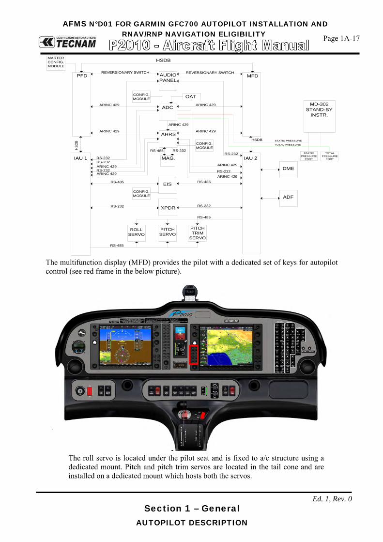
AFMS N°D01 FOR GARMIN GFC700 AUTOPILOT INSTALLATION AND RNAV/RNP NAVIGATION ELIGIBILITY Page 1A-17
Section 1 – General AUTOPILOT DESCRIPTION
Ed. 1, Rev. 0
PFD MFDAUDIOPANEL
ADC
AHRS
MAG.
EIS
XPDR
IAU 1 IAU 2
HSDB
RS-485 RS-485
RS-232
ARINC 429 ARINC 429
ARINC 429
RS-232RS-485
ARINC 429 ARINC 429
OAT
MASTERCONFIG.MODULE
CONFIG.MODULE
CONFIG.MODULE
CONFIG.MODULE
RS-232ARINC 429RS-232ARINC 429
RS-232ARINC 429
ARINC 429
REVERSIONARY SWITCHREVERSIONARY SWITCH
RS-232
RS-232RS-232
DME
ADF
HSDB
MD-302STAND-BY
INSTR.
STATICPRESSURE
PORT
TOTALPRESSURE
PORT
STATIC PRESSURETOTAL PRESSURE
HSDB
ROLLSERVO
PITCHSERVO
PITCHTRIM
SERVO
RS-485
RS-485
The multifunction display (MFD) provides the pilot with a dedicated set of keys for autopilot control (see red frame in the below picture).
The roll servo is located under the pilot seat and is fixed to a/c structure using a dedicated mount. Pitch and pitch trim servos are located in the tail cone and are installed on a dedicated mount which hosts both the servos.
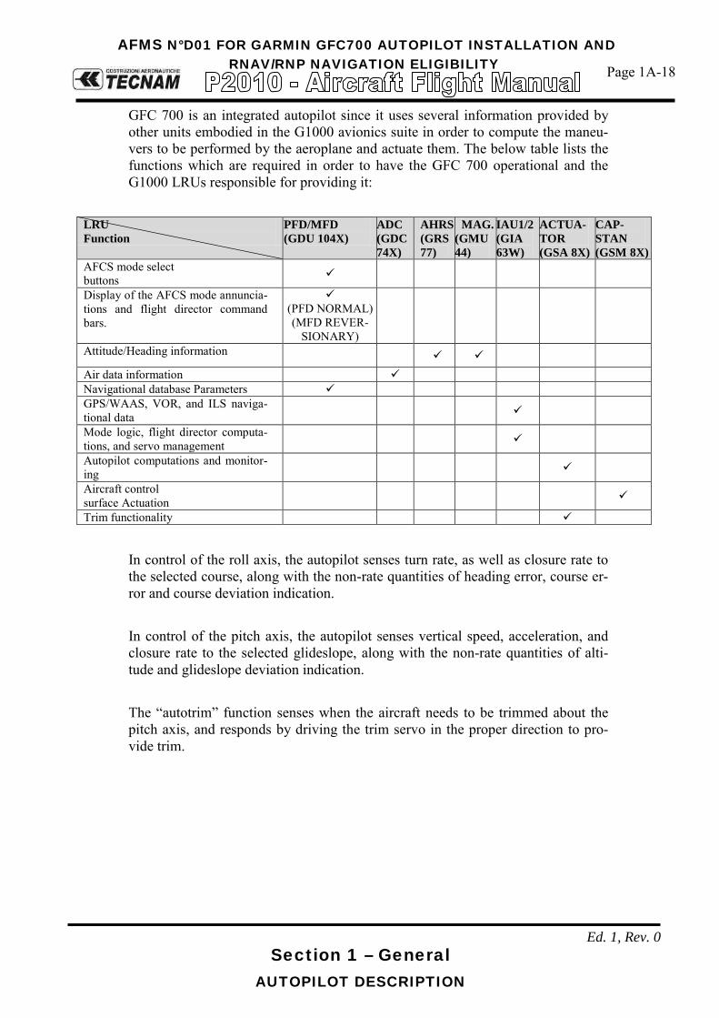
AFMS N°D01 FOR GARMIN GFC700 AUTOPILOT INSTALLATION AND RNAV/RNP NAVIGATION ELIGIBILITY Page 1A-18
Section 1 – General AUTOPILOT DESCRIPTION
Ed. 1, Rev. 0
GFC 700 is an integrated autopilot since it uses several information provided by other units embodied in the G1000 avionics suite in order to compute the maneu-vers to be performed by the aeroplane and actuate them. The below table lists the functions which are required in order to have the GFC 700 operational and the G1000 LRUs responsible for providing it:
LRU Function
PFD/MFD (GDU 104X)
ADC (GDC 74X)
AHRS (GRS 77)
MAG. (GMU 44)
IAU1/2 (GIA 63W)
ACTUA-TOR (GSA 8X)
CAP-STAN (GSM 8X)
AFCS mode select buttons
Display of the AFCS mode annuncia-tions and flight director command bars.
(PFD NORMAL) (MFD REVER-
SIONARY)
Attitude/Heading information Air data information Navigational database Parameters GPS/WAAS, VOR, and ILS naviga-tional data
Mode logic, flight director computa-tions, and servo management
Autopilot computations and monitor-ing
Aircraft control surface Actuation
Trim functionality
In control of the roll axis, the autopilot senses turn rate, as well as closure rate to the selected course, along with the non-rate quantities of heading error, course er-ror and course deviation indication. In control of the pitch axis, the autopilot senses vertical speed, acceleration, and closure rate to the selected glideslope, along with the non-rate quantities of alti-tude and glideslope deviation indication. The “autotrim” function senses when the aircraft needs to be trimmed about the pitch axis, and responds by driving the trim servo in the proper direction to pro-vide trim.

AFMS N°D01 FOR GARMIN GFC700 AUTOPILOT INSTALLATION AND RNAV/RNP NAVIGATION ELIGIBILITY Page 1A-19
Section 1 – General AUTOPILOT DESCRIPTION
Ed. 1, Rev. 0
12.1 GDU 1044 (MFD) GDU 1044 MFD unit can display as default engine parameters and moving map information, along with other information that can be selected by the pilot (see the first figure below); when reversionary mode is active it will display flight parame-ters (in the form of PFD with the left strip engine information, as can be seen in the second figure below). It is the user interface for P2010 avionics suite. GDU 1044 unit replaces the GDU 1040 unit on instrument panel RH side (MFD).
GDU 1044 (MFD)
Reversionary mode: - In the event of a single display failure the system is able to automatically
switch the critical information including flight and engine parameters on the remaining display presenting them in a compact view. In the event of a failure of the automatic switch logic, the pilot can easily force the reversionary mode by pressing the red button on the bottom of the audio panel thus getting both flight and engine parameters information, necessary for continued safe flight, on the remaining display.
GDU 1044 (MFD) in reversionary mode
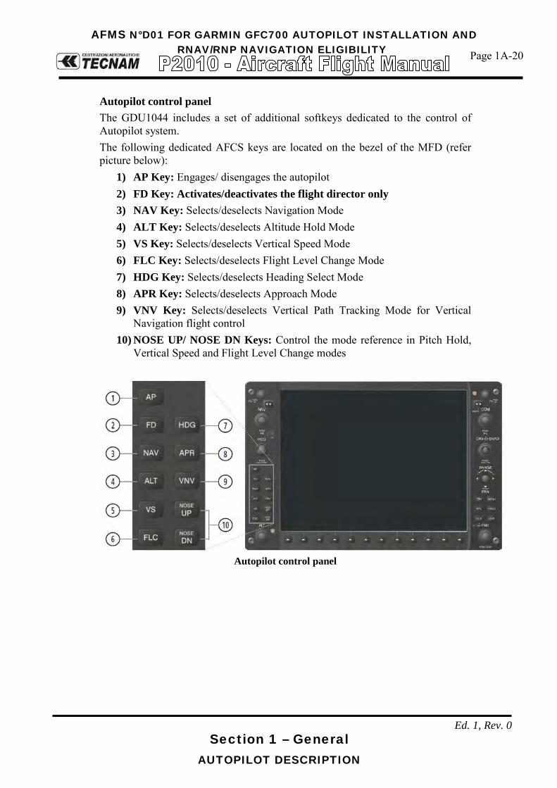
AFMS N°D01 FOR GARMIN GFC700 AUTOPILOT INSTALLATION AND RNAV/RNP NAVIGATION ELIGIBILITY Page 1A-20
Section 1 – General AUTOPILOT DESCRIPTION
Ed. 1, Rev. 0
Autopilot control panel The GDU1044 includes a set of additional softkeys dedicated to the control of Autopilot system. The following dedicated AFCS keys are located on the bezel of the MFD (refer picture below):
1) AP Key: Engages/ disengages the autopilot 2) FD Key: Activates/deactivates the flight director only 3) NAV Key: Selects/deselects Navigation Mode 4) ALT Key: Selects/deselects Altitude Hold Mode 5) VS Key: Selects/deselects Vertical Speed Mode 6) FLC Key: Selects/deselects Flight Level Change Mode 7) HDG Key: Selects/deselects Heading Select Mode 8) APR Key: Selects/deselects Approach Mode 9) VNV Key: Selects/deselects Vertical Path Tracking Mode for Vertical
Navigation flight control 10) NOSE UP/ NOSE DN Keys: Control the mode reference in Pitch Hold,
Vertical Speed and Flight Level Change modes
Autopilot control panel

AFMS N°D01 FOR GARMIN GFC700 AUTOPILOT INSTALLATION AND RNAV/RNP NAVIGATION ELIGIBILITY Page 1A-21
Section 1 – General AUTOPILOT DESCRIPTION
Ed. 1, Rev. 0
12.2 PILOT CONTROL WHEEL AND THROTTLE BUTTONS On the left side of pilot’s and copilot’s control wheels there are two PTT switches (the one on pilot control wheel is shown below as (1)) that, when pushed, allow radio transmission. These switches are momentaneous ones thus acting in such a way that when they are released the active COM device returns to the non-transmitting state. These switches are already installed in the basic aircraft which is not equipped with the autopilot. The following additional dedicated AFCS controls are located on the pilot control wheel, separately from the MFD, and on the throttle handle:
AP DISC Switch: Disengages the autopilot and interrupts pitch trim operation
This switch may be used to mute the aural autopilot disconnect alert.
AP Trim Switch: Used to command manual electric trim. This composite switch is split into left and right sides. The left switch is the ARM contact and the right switch controls the DN (forward) and UP (rearward) contacts. The AP TRIM ARM switch can be used to disengage the autopilot and to acknowledge an autopilot dis-connect alert and mute the associated aural tone. Manual trim commands are generated only when both sides of the switch are operated simultaneously. If either side of the switch is ac-tive separately for more than three seconds, MET function is disabled and ‘PTRM’ is displayed as the AFCS Status Annun-ciation on the PFD. The function remains disabled until both sides of the switch are inactivated.
CWS Button: While pressed, the Control Wheel Steering allows manual con-trol of the aircraft while the autopilot is engaged and synchro-nizes the flight director’s Command Bars with the current air-craft pitch (if not in Glideslope Mode) and roll (if in Roll Hold Mode). Upon release of the CWS Button, the flight director may establish new reference points, depending on the current pitch and roll modes. CWS operation details are discussed in the flight director modes section.
TO/GA Switch: The GA Switch is located on the throttle handle. Go Around and Takeoff modes are coupled pitch and roll modes and are annunciated as both the vertical and lateral modes when active. In these modes, the flight director commands a constant set pitch attitude and keeps the wings level. The GA Switch is used to select both modes. The mode entered by the flight director depends on wheth-er the aircraft is on the ground.

AFMS N°D01 FOR GARMIN GFC700 AUTOPILOT INSTALLATION AND RNAV/RNP NAVIGATION ELIGIBILITY Page 1A-22
Section 1 – General AUTOPILOT DESCRIPTION
Ed. 1, Rev. 0
The above mentioned AFCS controls are depicted in the below figures.
where:
1) PTT switch 2) AP DISC Switch 3) AP Trim Switch 4) CWS Button

AFMS N°D01 FOR GARMIN GFC700 AUTOPILOT INSTALLATION AND RNAV/RNP NAVIGATION ELIGIBILITY Page 1A-23
Section 1 – General AUTOPILOT DESCRIPTION
Ed. 1, Rev. 0

AFMS N°D01 FOR GARMIN GFC700 AUTOPILOT INSTALLATION AND RNAV/RNP NAVIGATION ELIGIBILITY Page 1A-24
Section 1 – General AUTOPILOT FUNCTIONS
Ed. 1, Rev.0
AUTOPILOT FUNCTIONS AND FEATURES 13GFC 700 autopilot suite is deeply integrated with Garmin G1000 avionics suite which integrates both the a/p controls and the sensors providing the required data to the servos. The GFC 700 AFCS is equipped with the following main operating functions:
• Flight Director (FD) — Flight director commands are displayed on the PFD. The
flight director provides: Command Bars showing pitch/roll guidance Pitch/roll mode selection and processing Autopilot communication
• Autopilot (AP) — Autopilot operation occurs within the pitch, roll, and pitch
trim servo and provides servo monitoring and automatic flight control in response to flight director steering commands, AHRS attitude and rate information, and air-speed.
• Manual Electric Trim (MET) — The pitch trim servo provides manual electric
trim capability when the autopilot is not engaged.
• ESP (Electronic Stability & Protection) keeps the aircraft within well defined op-erational limits thus preventing the pilot to operate the aircraft outside a specific envelope when it is being hand flown. This feature only operates when autopilot is not engaged and its operation is mutually exclusive with autopilot operation.
• USP (Underspeed Protection) is a flight director function that reacts to under-speed conditions in a way that allows the autopilot to remain engaged but prevents the airplane from stalling.

AFMS N°D01 FOR GARMIN GFC700 AUTOPILOT INSTALLATION AND RNAV/RNP NAVIGATION ELIGIBILITY Page 1A-25
Section 1 – General AUTOPILOT FUNCTIONS
Ed. 1, Rev.0
13.1 ESP Garmin GFC 700 is equipped with an envelope protection feature referred as ESP (Electronic Stability & Protection). Electronic Stability and Protection continu-ously monitors the aircraft. The system works by applying a correcting force to the controls in order to nudge pilot to avoid extreme attitudes that may bring the aircraft, if not corrected, to exceed normal flying envelope. This software feature aims to provide protection against aircraft operation outside a desired flight envelope. ESP will maintain the desired operating envelope, de-fined at autopilot development time, by automatically engaging one or more ser-vos when the aircraft is near the operating limit and nudging pilot to come back to nominal operating envelope. While ESP utilizes the same sensors, processors, and actuators as the GFC 700 autopilot, it is basically a separate function. ESP can be overpowered by the pilot and can be temporarily disabled using the AP disconnect or CWS switches. It functions independently of the aircraft’s autopilot system (although it uses the same control servos), so it basically operates “in back-ground” whenever the pilot is hand-flying the airplane. The ESP feature will only function with GPS available, A/P MASTER SWITCH ON (but autopilot not engaged) and aircraft above 200ft AGL.
ESP enabling:
As a standard, ESP will automatically set to enable at power-up. The system is configured in order to allow the pilot to disable ESP (or re-enable it if previously disabled after power up) via the AUX – SYSTEM SETTINGS page on MFD. If ESP has been disabled via MFD, it will automatically be set to ON upon any battery/power reset. ESP function uses the same servos that provide autopilot functionality while auto-pilot is not engaged, as such, if power is cut from these servos both autopilot and ESP functions will be unavailable. Based on the above if “AUTOPILOT MASTER” is set to OFF, power to servos is cut irrespectively of their mode of operation (autopilot or ESP). The pilot can interrupt ESP by pressing and holding either the Control Wheel Steering (CWS) or Autopilot Disconnect (AP DISC TRIM INTRPT) switch. Up-on releasing the CWS or AP DISC TRIM INTRPT switch, ESP force will again be applied, provided aircraft attitude and/or airspeed are within their respective engagement limits. ESP can be enabled or disabled on the AUX-SYSTEM SETUP 2 Page on the MFD.

AFMS N°D01 FOR GARMIN GFC700 AUTOPILOT INSTALLATION AND RNAV/RNP NAVIGATION ELIGIBILITY Page 1A-26
Section 1 – General AUTOPILOT FUNCTIONS
Ed. 1, Rev.0
To enable or disable ESP:
1) Turn the large FMS Knob to select the AUX Page Group. 2) Turn the small FMS Knob to select the System Setup Page. 3) If necessary, select the SETUP 2 Softkey to display the AUX-SYSTEM
SETUP 2 Page.If the AUX-SYSTEM SETUP 2 is already displayed, pro-ceed to step 4.
4) Press the FMS Knob to activate the cursor. 5) Turn the large FMS Knob to place cursor in the STABILITY & PRO-
TECTION field. 6) Turn the small FMS Knob to select ‘ENABLE’ or ‘DISABLE’. 7) Press the FMS Knob to remove the cursor.
ESP engagement and operation:
ESP is automatically enabled on system power up.
ESP unavailability and/or failure is indicated to the pilot on PFD by the advisory “ESP not available” on alert window.
ESP will turn OFF upon loss of both GPS. The ADVSY “ESP OFF” will appear on the alert window in case of loss of both GPS.
13.1.1 PITCH MODE Pitch attitude boundaries are set based on P2010 aircraft performances. Since pitch ESP augments the natural aircraft longitudinal stability, no special simbolo-gy is required. Value that have been set-up for the P2010 are as follows:
Nose above the horizon: Engagement low threshold: + 15° Engagement upper threshold: + 18° Lower disengage threshold: + 12°
Nose below the horizon: Engagement low threshold: -15° Engagement upper threshold: -20° Lower disengage threshold: -13°
ESP utilizes electronic torque and speed commands to augment the aircraft’s sta-bility: it uses an Electronic Torque Limit (ETL) and an Electronic Speed Limit (ESL) to limit the maximum authority of the ESP function. ESP is inactive when the pitch attitude is within the positive and negative engagement limits defined in the certification gain file.
NOTE
NOTE

AFMS N°D01 FOR GARMIN GFC700 AUTOPILOT INSTALLATION AND RNAV/RNP NAVIGATION ELIGIBILITY
Page 1A-27
Section 1 – General AUTOPILOT FUNCTIONS
Ed. 1, Rev.0
When the aircraft reaches the engagement limit, ESP ramps up the servo torque command to adjust the aircraft back toward zero pitch attitude. ESP uses a rate command to drive the attitude back to the nominal range and does not try to con-trol to a specific attitude. As the pitch attitude returns to the nominal range, the torque and pitch rate are reduced until the aircraft reaches the disengagement limit at which time ESP turns off. The disengagement threshold is sized so that the transition from ESP being active to being inactive is transparent to the pilot (no transient when ESP turns off). If, when ESP engages, the aircraft continues to pitch away from the nominal atti-tude range the torque command will increase with increasing pitch deviation. Above the upper disengagement limit specified in the certification gain file ESP will be disabled.
13.1.2 ROLL MODE Roll mode is similar to pitch mode and also utilizes configurable gain file parame-ters to define engagement and disengagement limits as well as the speed and torque curves. The engagement and disengagement attitude limits are displayed with double hash marks on the roll indicator when ESP is available and /or active. The lack of dou-ble hash marks above 200 ft AGL (when autopilot is not connected) is a clear in-dication that ESP is not available. Values for the symmetric roll attitude limits are as follows:
Engagement low threshold: +/- 45° Engagement upper threshold: +/- 75° Lower disengage threshold: +/- 30°
Electronic stability and protection action starts at the predetermined bank angle. Since crossing this bank angle results in a change in aircraft stability (and there-fore handling characteristics) indications of this boundary are provided to the pi-lot.
When ESP is inactive (roll attitude within nominal limits) only the engagement limits are displayed in order to reduce clutter on the roll indicator. As the bank
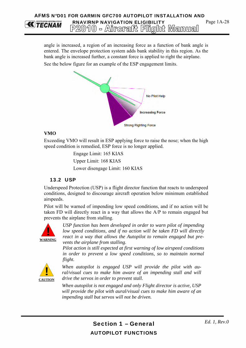
AFMS N°D01 FOR GARMIN GFC700 AUTOPILOT INSTALLATION AND RNAV/RNP NAVIGATION ELIGIBILITY
Page 1A-28
Section 1 – General AUTOPILOT FUNCTIONS
Ed. 1, Rev.0
angle is increased, a region of an increasing force as a function of bank angle is entered. The envelope protection system adds bank stability in this region. As the bank angle is increased further, a constant force is applied to right the airplane. See the below figure for an example of the ESP engagement limits.
VMO Exceeding VMO will result in ESP applying force to raise the nose; when the high speed condition is remedied, ESP force is no longer applied.
Engage Limit: 165 KIAS Upper Limit: 168 KIAS Lower disengage Limit: 160 KIAS
13.2 USP Underspeed Protection (USP) is a flight director function that reacts to underspeed conditions, designed to discourage aircraft operation below minimum established airspeeds. Pilot will be warned of impending low speed conditions, and if no action will be taken FD will directly react in a way that allows the A/P to remain engaged but prevents the airplane from stalling.
WARNING
USP function has been developed in order to warn pilot of impending low speed conditions, and if no action will be taken FD will directly react in a way that allows the Autopilot to remain engaged but pre-vents the airplane from stalling. Pilot action is still expected at first warning of low airspeed conditions in order to prevent a low speed conditions, so to maintain normal flight.
CAUTION
When autopilot is engaged USP will provide the pilot with au-ral/visual cues to make him aware of an impending stall and will drive the servos in order to prevent stall. When autopilot is not engaged and only Flight director is active, USP will provide the pilot with aural/visual cues to make him aware of an impending stall but servos will not be driven.

AFMS N°D01 FOR GARMIN GFC700 AUTOPILOT INSTALLATION AND RNAV/RNP NAVIGATION ELIGIBILITY
Page 1A-29
Section 1 – General AUTOPILOT FUNCTIONS
Ed. 1, Rev.0
How Underspeed Protection functions depends on which vertical flight director mode is selected. For the purpose of this discussion, the vertical flight director modes can be divid-ed into two categories:
- It is important to maintain altitude for as long as possible (altitude-critical modes).
- Maintaining altitude is less crucial (non-altitude critical modes).
CAUTION
If USP engages while Autopilot is in PIT or VS mode, and power is ab-ruptly set to full throttle, pilot may expect a slight nose up tendency that will be quickly counteracted by autopilot. This is a normal behaviour, the slight nose up tendency in this case will be due to abrupt power advance, but will be immediately damped by Autopilot (with PIT or VS turning green on the annunciation panel).
CAUTION
USP engagement is a consequence of autopilot failing to properly moni-toring A/P and aircraft behaviour. This is mainly caused by a pilot re-quest that cannot be fulfilled due to lack of power coupled with unattain-able pitch input. Pilot need to continuously monitor autopilot performance, while checking that mode selections are compatible with aircraft performance.
CAUTION
If Autopilot is engaged in FLC mode, FLC mode will downgrade to PIT mode when in USP for more than 10 seconds.
CAUTION
If USP engages while in ALT mode, upon USP disengagement FD will com-mand bars to regain pre-selected altitude (altitude selected before USP en-gagement). Pilot must monitor A/P to check if previous pre-selected altitude is still attainable with energy available. It is recommended in this case to pre-select a new altitude in order to speed-up energy management and recover from slow speed conditions.
When USP becomes active, expect a small FD adjustment due to reaction to very low speed condition.
NOTE

AFMS N°D01 FOR GARMIN GFC700 AUTOPILOT INSTALLATION AND RNAV/RNP NAVIGATION ELIGIBILITY
Page 1A-30
Section 1 – General AUTOPILOT FUNCTIONS
Ed. 1, Rev.0
13.2.1 ALTITUDE CRITICAL MODES (ALT, GS, GP, TO, GA, FLC)
When the airspeed trend vector (dedicated algorithm) reaches 65 +/- 2 KIAS a single aural “AIRSPEED” will sound, alerting the pilot to the impending under-speed condition, which requires pilot action. If the aircraft decelerates to stall warning and a speed of 65 KIAS is reached, the lateral and vertical flight director modes will change from active to armed and the autopilot will provide input causing the aircraft to pitch down and the wings to level.
The aural “AIRSPEED” alert will sound every five seconds. If aircraft is unintentionally decelerated to 65 KIAS, a MINSPD annunciation posts above the airspeed tape on PFD in alternating amber and black text. A red “UNDERSPEED PROTECT ACTIVE” annunciation will appear to the right of the vertical speed indicator. USP will drive the pitch down until the indicated air-speed increases above 70 KIAS or stall warning turns off, plus two knots (which-ever comes first). When USP disengages, autopilot will cause the aircraft to pitch up until recaptur-ing the vertical reference (vertical and lateral flight director modes will change from white armed to green active).

AFMS N°D01 FOR GARMIN GFC700 AUTOPILOT INSTALLATION AND RNAV/RNP NAVIGATION ELIGIBILITY
Page 1A-31
Section 1 – General AUTOPILOT FUNCTIONS
Ed. 1, Rev.0
13.2.2 NON ALTITUDE CRITICAL MODES (VS, VNAV, IAS) When the airspeed trend vector (dedicated algorithm) reaches 65 +/- 2 KIAS a single aural “AIRSPEED” will sound, alerting the pilot to the impending under-speed condition, which requires pilot action. If the aircraft is allowed to decelerate to an IAS below the minimum commanda-ble autopilot airspeed (65 Kts for P2010), a red “UNDERSPEED PROTECT AC-TIVE” annunciation appear to the right of the vertical speed indicator. Vertical flight director mode will change from active to armed, Flight Director and autopilot will command the aircraft to pitch down until reaching a pitch atti-tude at which IAS equals at least the minimum commandable autopilot airspeed, avoiding the development of a stall condition.
When airspeed increases (as a result of adding power/thrust) to an IAS above 70 KIAS, USP will then disengage and the autopilot will command the aircraft to pitch up until recapturing the vertical reference (vertical vertical flight director mode will switch from white armed to green active).

Page D01-7
Section 9 – Supplements - Supplement no. D01 – GARMIN GFC700 AUTOPILOT INSTALLATION AND RNAV/RNP
NAVIGATION ELIGIBILITY
Ed. 1, Rev.0
INTENTIONALLY LEFT BLANK

Page D01-8
Section 9 – Supplements - Supplement no. D01 – GARMIN GFC700 AUTOPILOT INSTALLATION AND RNAV/RNP
NAVIGATION ELIGIBILITY
Ed. 1, Rev.0
SECTION 2 – LIMITATIONS Make sure you first applied instructions reported on the basic AFM,
Section 2 Limitations
According to A/C configuration apply following pages replacement:
Supplement D01 LIMITATIONS
page
AFM Section 2
page 2A-15 REPLACES 2-15 of basic AFM, Section 2
2A-17 thru 20 REPLACES 2-17 of basic AFM, Section 2
Supplement D01: pages replacement instructions

Page D01-9
Section 9 – Supplements - Supplement no. D01 – GARMIN GFC700 AUTOPILOT INSTALLATION AND RNAV/RNP
NAVIGATION ELIGIBILITY
Ed. 1, Rev.0
INTENTIONALLY LEFT BLANK

AFMS N°D01 FOR GARMIN GFC700 AUTOPILOT INSTALLATION AND RNAV/RNP NAVIGATION ELIGIBILITY
Page 2A-15
Section 2 – Limitations LIMITATIONS PLACARDS
Ed. 1, Rev. 0
19 LIMITATIONS PLACARDS Hereinafter limitation placards, related to the operating limitations, are placed in plain view on the pilot.
19.1 SPEED LIMITATIONS On the left side instrument panel, above on the left, it is placed the following placard reporting the speed limitations:
19.2 OPERATING LIMITATIONS On the central side of the instrument panel, the following placard is placed re-minding the observance of aircraft operating limitations according to installed equipment configuration, see KOEL paragraph 18.
When the Autopilot is installed, next placard is added on the instrument panel to the right of the preceding one:
19.3 NO SMOKING PLACARD On the right hand side of the instrument panel the following placard is placed re-minding the observance for “no smoking”:

AFMS N°D01 FOR GARMIN GFC700 AUTOPILOT INSTALLATION AND RNAV/RNP NAVIGATION ELIGIBILITY
Page 2A-17
Section 2 – Limitations AUTOPILOT LIMITATIONS
Ed. 1, Rev. 0
AUTOPILOT LIMITATIONS 20
The “Garmin G1000 Pilot’s Guide for the Tecnam P2010” (Part No. 190-01830-00 Revision A dated September 25, 2014 or a more up-dated version) must be carried in the aircraft and made available to the pilot at all time.
Following operating limitations shall apply when the aircraft is equipped with Garmin GFC700 Autopilot:
• The Autopilot is certified for Category I – ILS Approaches [with a deci-sion height not lower than 200 ft AGL (61 m)]
• During Autopilot operation, a pilot with seat belt fastened must be seated at the left pilot position
• Maximum speed for Autopilot operation is 150 KIAS • Do not use autopilot for airspeed below 70 KIAS • Minimum approach speed is 70 KIAS • The autopilot must be OFF during takeoff and landing • Minimum altitude AGL for Autopilot operation is:
b. Cruise and Descent: 800 ft (244 m) AGL c. Climb after Take-off: 400 ft (122 m) AGL d. ILS CAT I precision approach: 200 ft (61 m) AGL
• Use of the autopilot or manual electric trim system is prohibited before the satisfactory completion of the Pre-flight procedure.
• Autopilot USP function requires flaps indicators lights in the cockpit to be efficient for correct operation. If one flap indicator light gets inoperative during flight, USP function is not assured.
NOTE

AFMS N°D01 FOR GARMIN GFC700 AUTOPILOT INSTALLATION AND RNAV/RNP NAVIGATION ELIGIBILITY
Page 2A-18
Ed 1, Rev. 0
Section 2 – Limitations PBN (RNAV & RNP) OPERATIONAL ELIGIBILITY
PBN (RNAV & RNP) OPERATIONAL ELIGIBILITY 21
21.1 GENERAL GNSS NAVIGATION EQUIPMENT APPROVALS The GPS/GNSS receivers in the G1000 System are certified to TSO C129a Class A1 and ETSO C129a Class A1 or TSO C145a and ETSO 2C145a. The Garmin GNSS navigation system as installed in this airplane complies with the requirements of AC 20-138A, JAA TGL-10 and AMCs 20-4A, 20-27A and 20-28. It’s approved for navigation using GPS and SBAS (within the coverage of a Satel-lite Based Augmentation System complying with ICAO Annex 10) for IFR en route, terminal area, precision and non-precision approach operations. The G1000 System meets the requirements for GPS/GNSS as a Primary Means of Navigation for Oceanic/Remote Operations (RNP-10) per AC 20-138C, FAA No-tice N8110.60, FAA Order 8400-12C and FAA Order 8700-1. Both GPS/GNSS receivers are required to be operating and receiving usable signals except for routes requiring only one Long Range Navigation sensor. In accordance to ICAO doc 9613 (Fouth Edition – 2013), the G1000 System has been shown to be eligible for:
- B-RNAV (RNAV-5) per AMC 20-4A. - RNAV1 / P-RNAV (RNP-1) Enroute and Terminal navigation per JAA
TGL-10 Rev.1. - RNP APCH LNAV/VNAV per EASA AMC 20-27. This does not include
APV BARO-VNAV operation which is not cleared. - LPV with SBAS per EASA AMC 20-28.
provided that the G1000 is receiving usable navigation information from at least one GPS receiver.

AFMS N°D01 FOR GARMIN GFC700 AUTOPILOT INSTALLATION AND RNAV/RNP NAVIGATION ELIGIBILITY
Page 2A-19
Ed 1, Rev. 0
Section 2 – Limitations PBN (RNAV & RNP) OPERATIONAL ELIGIBILITY
21.2 G1000 GNSS (GPS/SBAS) NAVIGATION SYSTEM LIMITA-
TIONS The pilot must confirm at system initialization that the Navigation database is cur-rent. Navigation database is expected to be current for the duration of the flight. If the AIRAC cycle will change during flight, the pilot must ensure the accuracy of navigation data, including suitability of navigation facilities used to define the routes and procedures for flight. If an amended chart affecting navigation data is published for the procedure, the database must not be used to conduct the proce-dure. GPS/SBAS based IFR enroute, oceanic, and terminal navigation is prohibited un-less the pilot verifies and uses a valid, compatible, and current Navigation data-base or verifies each waypoint for accuracy by reference to current approved data. Discrepancies that invalidate a procedure must be reported to Garmin Internation-al. The affected procedure is prohibited from being flown using data from the Navigation database until a new Navigation database is installed in the airplane and verified that the discrepancy has been corrected. Contact information to report Navigation database discrepancies can be found at www.Garmin.com>Support>Contact Garmin Support>Aviation. Pilots and opera-tors can view navigation data base alerts at www.Garmin.com > In the Air> Nav-Data Alerts. For flight planning purposes, in areas where SBAS coverage is not available, the pilot must check RAIM availability. Within Europe, RAIM availability can be determined using the G1000 WFDE Prediction program or Europe's AUGER GPS RAIM Prediction Tool at http://augur.ecacnav.com/augur/app/home. This requirement is not necessary if SBAS coverage is confirmed to be available along the entire route of flight. The route planning andWFDE prediction program may be downloaded from the GARMIN G1000 website on the internet. For information on using the WFDE Prediction Program, refer to GARMIN WAAS FDE Prediction Program, part number 190-00643-01, `WFDE Prediction Program instructions'. For flight planning purposes for operations within European B-RNAV and P-RNAV airspace, if more than one satellite is scheduled to be out of service, then the availability of GPS integrity RAIM shall be confirmed for the intended flight (route and time). In the event of a predicted continuous loss of RAIM of more than five minutes for any part of the intended flight, the flight should be delayed, cancelled, or re-routed on a track where RAIM requirements can be met. Both GPS navigation receivers must be operating and providing GPS navigation guidance to the PFD for operations requiring RNP-4 performance. Whenever possible, RNP and RNAV routes including Standard Instrument Depar-tures (SIDs) and Obstacle Departure Procedures (ODPs), Standard Terminal Arri-val (STAR), and enroute RNAV ”Q” and RNAV ”T” routes should be loaded into

AFMS N°D01 FOR GARMIN GFC700 AUTOPILOT INSTALLATION AND RNAV/RNP NAVIGATION ELIGIBILITY
Page 2A-20
Ed 1, Rev. 0
Section 2 – Limitations PBN (RNAV & RNP) OPERATIONAL ELIGIBILITY
the flight plan from he database in their entirety, rather than loading route way-points from the database into the flight plan individually. Selecting and inserting individual named fixes from the database is permitted, provided all fixes along the published route to be flown are inserted. ”GPS”, ”or GPS”, and ”RNAV (GPS)” instrument approaches using the G1000 System are prohibited unless the pilot verifies and uses the current Navigation database. GPS based instrument ap-proaches must be flown in accordance with an approved instrument approach pro-cedure that is loaded from the Navigation database. Not all published Instrument Approach Procedures (IAP) are in the Navigation database. Pilots planning on flying an RNAV instrument approach must ensure that the Navigation database contains the planned RNAV Instrument Approach Procedure and that approach procedure must be loaded from the Navigation database into the FMS flight plan by its name. The navigation equipment required to join and fly an instrument approach proce-dure is indicated by the title of the procedure and notes on the IAP chart. Use of the GARMIN G1000 GPS/SBAS receivers to provide navigation guidance during the final approach segment of an ILS, LOC, LOC-BC, LDA, SDF,MLS or any other type of approach not approved for ”or GPS” navigation is prohibited. When using the G1000 VOR/LOC/GS receivers to fly the final approach segment, VOR/LOC/GS navigation data must be selected and presented on the CDI. SID/STAR The use of SIDs and STARs stored in GPS data base is only authorized, if the pi-lot has checked that GPS procedure corresponds to the one given in the official documentation (coordinates of various points and paths between points).

Page D01-10
Ed 1, Rev. 0 Section 9 – Supplements -
Supplement no. D01 – GARMIN GFC700 AUTOPILOT INSTALLATION AND RNAV/RNP NAVIGATION ELIGIBILITY
INTENTIONALLY LEFT BLANK

Page D01-11
Ed 1, Rev. 0 Section 9 – Supplements -
Supplement no. D01 – GARMIN GFC700 AUTOPILOT INSTALLATION AND RNAV/RNP NAVIGATION ELIGIBILITY
SECTION 3 – EMERGENCY PROCEDURES Make sure you first applied instructions reported on the basic AFM,
Section 3 Emergency Procedures
According to A/C configuration apply following pages replacement:
Supplement D01 EMERGENCY PROCEDURES
page
AFM Section 3
page 3A-31 thru 35 REPLACES *Added at the end of Section 3 of basic AFM
Supplement D01: pages replacement instructions

Page D01-12
Ed 1, Rev. 0 Section 9 – Supplements -
Supplement no. D01 – GARMIN GFC700 AUTOPILOT INSTALLATION AND RNAV/RNP NAVIGATION ELIGIBILITY
INTENTIONALLY LEFT BLANK

AFMS N°D01 FOR GARMIN GFC700 AUTOPILOT INSTALLATION AND RNAV/RNP NAVIGATION ELIGIBILITY
Page 3A-31
Section 3 – Emergency procedures AUTOPILOT EMERGENCY PROCEDURES
Ed. 1, Rev. 0
AUTOPILOT EMERGENCY PROCEDURES 12
In the event of autopilot malfunction, or when the system is not per-forming as expected or commanded, take immediately the aircraft control disconnecting the autopilot which must be set inoperative until the failure has been identified and corrected.
12.1 AUTOPILOT HARDOVER OR FAILURE TO HOLD THE SELECTED
HEADING In case of A/P hardover or failure to hold selected heading, apply following pro-cedure:
Accomplish items 1 and 2 simultaneously:
1. Airplane control wheel GRASP FIRMLY and OVERPOWER if necessary to regain aircraft control
2. AP DISC/TRIM INTR switch PRESS
3. AP MASTER SWITCH OFF
4. AP Circuit Breaker PULL
WARNING
Following an A/P or MET system malfunction, do not engage the autopilot until the cause of the malfunction has been cor-rected.
When Autopilot is disconnected, it may be necessary operate the pitch trim through either the Manual Electric Trim Switch or the Trim Wheel.
NOTE
NOTE
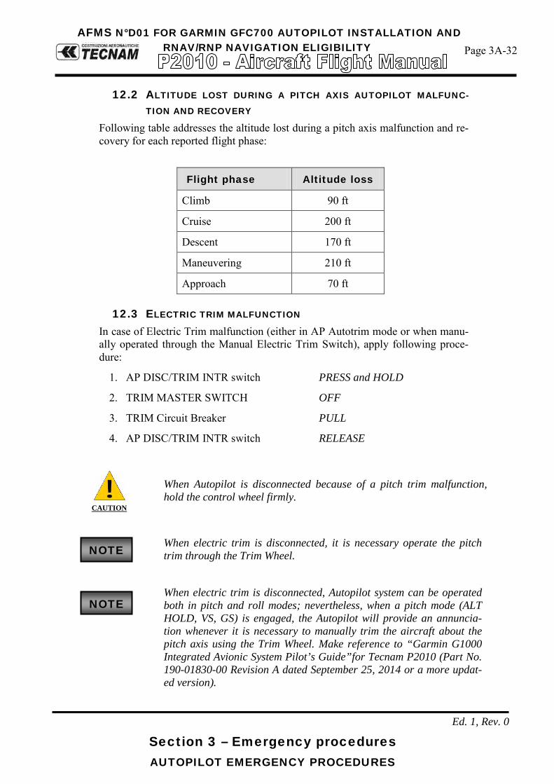
AFMS N°D01 FOR GARMIN GFC700 AUTOPILOT INSTALLATION AND RNAV/RNP NAVIGATION ELIGIBILITY
Page 3A-32
Section 3 – Emergency procedures AUTOPILOT EMERGENCY PROCEDURES
Ed. 1, Rev. 0
12.2 ALTITUDE LOST DURING A PITCH AXIS AUTOPILOT MALFUNC-
TION AND RECOVERY Following table addresses the altitude lost during a pitch axis malfunction and re-covery for each reported flight phase:
Flight phase Altitude loss
Climb 90 ft
Cruise 200 ft
Descent 170 ft
Maneuvering 210 ft
Approach 70 ft
12.3 ELECTRIC TRIM MALFUNCTION In case of Electric Trim malfunction (either in AP Autotrim mode or when manu-ally operated through the Manual Electric Trim Switch), apply following proce-dure:
1. AP DISC/TRIM INTR switch PRESS and HOLD
2. TRIM MASTER SWITCH OFF
3. TRIM Circuit Breaker PULL
4. AP DISC/TRIM INTR switch RELEASE
CAUTION
When Autopilot is disconnected because of a pitch trim malfunction, hold the control wheel firmly.
When electric trim is disconnected, it is necessary operate the pitch
trim through the Trim Wheel.
When electric trim is disconnected, Autopilot system can be operated
both in pitch and roll modes; nevertheless, when a pitch mode (ALT HOLD, VS, GS) is engaged, the Autopilot will provide an annuncia-tion whenever it is necessary to manually trim the aircraft about the pitch axis using the Trim Wheel. Make reference to “Garmin G1000 Integrated Avionic System Pilot’s Guide”for Tecnam P2010 (Part No. 190-01830-00 Revision A dated September 25, 2014 or a more updat-ed version).
NOTE
NOTE

AFMS N°D01 FOR GARMIN GFC700 AUTOPILOT INSTALLATION AND RNAV/RNP NAVIGATION ELIGIBILITY
Page 3A-33
Section 3 – Emergency procedures AUTOPILOT EMERGENCY PROCEDURES
Ed. 1, Rev. 0
12.4 AMPLIFIED EMERGENCY PROCEDURES The following observations provide additional information for more complete un-derstanding of the recommended course(s) of action in emergency situations.
1. An autopilot or autotrim malfunction occurs when there is an un-commanded deviation in the airplane flight path or when there is abnormal control wheel or trim wheel motion. In some cases, (es-pecially for autopilot trim), there may be little to no airplane mo-tion, but the PITCH TRIM annunciator (LH side of PDF) may come on.
2. The primary concern in reacting to an autopilot or autopilot trim
system malfunction, or to an automatic disconnect of the autopilot, is to keep control of the airplane. Immediately grasp the control wheel and push and hold the A/P DISC/TRIM INT switch throughout the recovery. Manipulate the controls as required to safely keep the airplane within all of its operating limitations. Ele-vator trim should be used manually as needed to relieve control forces. Switch the AP MASTER SWITCH to OFF and, when time is available after aircraft recovery, open (pull) the AUTOPILOT cir-cuit breaker on the lower right hand corner of the circuit breaker panel to completely disable the autopilot system.
3. A MET (Manual Electric Trim) system malfunction (without pilot
actuation of the manual electric trim switches) may be recognized by the PITCH TRIM annunciator coming on or by unusual trim wheel motions with the autopilot not engaged. As with an autopilot malfunction, the first concern following a manual electric trim sys-tem malfunction is to keep the airplane in control. Grasp the con-trol wheel firmly and push and hold down the A/P DISC/TRIM INT switch. Switch the trim cut-out switch to OFF.
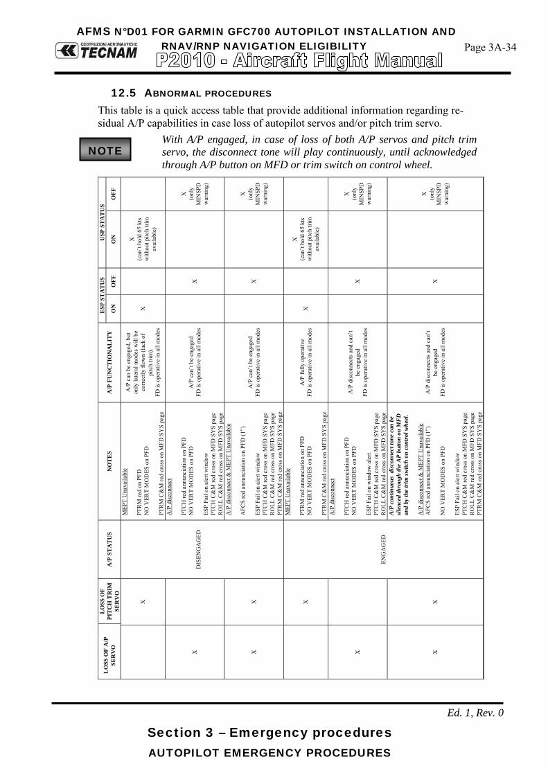
AFMS N°D01 FOR GARMIN GFC700 AUTOPILOT INSTALLATION AND RNAV/RNP NAVIGATION ELIGIBILITY
Page 3A-34
Section 3 – Emergency procedures AUTOPILOT EMERGENCY PROCEDURES
Ed. 1, Rev. 0
12.5 ABNORMAL PROCEDURES This table is a quick access table that provide additional information regarding re-sidual A/P capabilities in case loss of autopilot servos and/or pitch trim servo.
With A/P engaged, in case of loss of both A/P servos and pitch trim servo, the disconnect tone will play continuously, until acknowledged through A/P button on MFD or trim switch on control wheel.
LO
SS O
F A
/P
SER
VO
L
OSS
OF
PIT
CH
TR
IM
SER
VO
A
/P S
TA
TU
S N
OT
ES
A/P
FU
NC
TIO
NA
LIT
Y
ESP
ST
AT
US
USP
ST
AT
US
ON
O
FF
ON
O
FF
X
DIS
ENG
AG
ED
MEP
T U
nava
ilabl
e PT
RM
red
on P
FD
NO
VER
T M
OD
ES o
n PF
D
PTR
M C
&M
red
cros
s on
MFD
SY
S pa
ge
A/P
can
be
enga
ged,
but
on
ly la
tera
l mod
es w
ill b
e co
rrect
ly fl
own
(lack
of
pitc
h tri
m).
FD
is o
pera
tive
in a
ll m
odes
X
X
(can
’t ho
ld 6
5 kt
s w
ithou
t pitc
h tri
m
avai
labl
e)
X
A/P
disc
onne
ct
PTC
H re
d an
nunc
iatio
n on
PFD
N
O V
ERT
MO
DES
on
PFD
ES
P Fa
il on
ale
rt w
indo
w
PTC
H C
&M
red
cros
s on
MFD
SY
S pa
ge
RO
LL C
&M
red
cros
s on
MFD
SY
S pa
ge
A/P
can
’t be
eng
aged
FD
is o
pera
tive
in a
ll m
odes
X
X
(o
nly
MIN
SPD
w
arni
ng)
X
X
A/P
disc
onne
ct &
MEP
T U
nava
ilabl
e
AFC
S re
d an
nunc
iatio
n on
PFD
(1”)
ES
P Fa
il on
ale
rt w
indo
w
PTC
H C
&M
red
cros
s on
MFD
SY
S pa
ge
RO
LL C
&M
red
cros
s on
MFD
SY
S pa
ge
PTR
M C
&M
red
cros
s on
MFD
SY
S pa
ge
A/P
can
’t be
eng
aged
FD
is o
pera
tive
in a
ll m
odes
X
X
(o
nly
MIN
SPD
w
arni
ng)
X
ENG
AG
ED
MEP
T U
nava
ilabl
e PT
RM
red
annu
ncia
tion
on P
FD
NO
VER
T M
OD
ES o
n PF
D
PTR
M C
&M
red
cros
s on
MFD
SY
S pa
ge
A/P
fully
ope
rativ
e FD
is o
pera
tive
in a
ll m
odes
X
X
(can
’t ho
ld 6
5 kt
s w
ithou
t pitc
h tri
m
avai
labl
e)
X
A/P
disc
onne
ct
PTC
H re
d an
nunc
iatio
n on
PFD
N
O V
ERT
MO
DES
on
PFD
ES
P Fa
il on
win
dow
ale
rt PT
CH
C&
M re
d cr
oss o
n M
FD S
YS
page
R
OLL
C&
M re
d cr
oss o
n M
FD S
YS
page
A/P
disc
onne
cts a
nd c
an’t
be e
ngag
ed
FD is
ope
rativ
e in
all
mod
es
X
X
(onl
y M
INSP
D
war
ning
)
X
X
A/P
con
tinuo
us d
isco
nnec
t ton
e ca
n be
si
lenc
ed th
roug
h th
e A
P bu
tton
on M
FD
an
d by
the
trim
switc
h on
con
trol
whe
el.
A/P
disc
onne
ct &
MEP
T U
nava
ilabl
e
AFC
S re
d an
nunc
iatio
n on
PFD
(1”)
N
O V
ERT
MO
DES
on
PFD
ES
P Fa
il on
ale
rt w
indo
w
PTC
H C
&M
red
cros
s on
MFD
SY
S pa
ge
RO
LL C
&M
red
cros
s on
MFD
SY
S pa
ge
PTR
M C
&M
red
cros
s on
MFD
SY
S pa
ge
A/P
disc
onne
cts a
nd c
an’t
be e
ngag
ed
FD is
ope
rativ
e in
all
mod
es
X
X
(onl
y M
INSP
D
war
ning
)
NOTE

AFMS N°D01 FOR GARMIN GFC700 AUTOPILOT INSTALLATION AND RNAV/RNP NAVIGATION ELIGIBILITY
Page 3A-35
Section 3 – Emergency procedures AUTOPILOT EMERGENCY PROCEDURES
Ed. 1, Rev. 0
This table is a quick access table that provide additional information regarding re-sidual A/P capabilities in case of loss of PFD or MFD.
PFD MFD NOTES
ON → OFF ON A/P reverts to PIT & ROLL (from any mode selected) No aurals from A/P (both A/P DISC & USP)
ON ON → OFF
A/P stays in the selected mode A/P control keyboard unavailable A/P can be disconnected with A/P DISC button on control wheel FD command bars cannot be eliminated ESP Off on alert window on PFD
ON → OFF ON → OFF A/P automatically disconnects after ~ 4 to 5 seconds A/P disconnection tone plays endlessly until A/P DISC button is pressed

Page D01-13
Section 9 – Supplements - Supplement no. D01 – GARMIN GFC700 AUTOPILOT INSTALLATION AND RNAV/RNP
NAVIGATION ELIGIBILITY
Ed. 1, Rev. 0
INTENTIONALLY LEFT BLANK
Page D01-14
Section 9 – Supplements - Supplement no. D01 – GARMIN GFC700 AUTOPILOT INSTALLATION AND RNAV/RNP
NAVIGATION ELIGIBILITY
Ed. 1, Rev.0
SECTION 4 – NORMAL PROCEDURES Make sure you first applied instructions reported on the basic AFM,
Section 4 Normal Procedures
According to A/C configuration apply following pages replacement:
Supplement D01 NORMAL PROCEDURES
page
AFM Section 4
page 4A-27 thru 38 REPLACES *Added at the end of Section 4 of basic AFM
Supplement D01: pages replacement instructions

Page D01-15
Section 9 – Supplements - Supplement no. D01 – GARMIN GFC700 AUTOPILOT INSTALLATION AND RNAV/RNP
NAVIGATION ELIGIBILITY
Ed. 1, Rev.0
INTENTIONALLY LEFT BLANK

AFMS N°D01 FOR GARMIN GFC700 AUTOPILOT INSTALLATION AND RNAV/RNP NAVIGATION ELIGIBILITY
Page 4A-27
Section 4 – Normal procedures AUTOPILOT NORMAL PROCEDURES
Ed. 1, Rev.0
AUTOPILOT NORMAL PROCEDURES 6
For detailed description of A/P selections, behaviour and display out-look, refer to the “Garmin G1000 Pilot’s Guide for the Tecnam P2010” (Part No. 190-01830-00 Revision A dated September 25, 2014 or a more updated version); it must be always carried in the aircraft and made available to the pilot at all time.
If A/P Master switch and /or Trim disconnect switch are inadvertently switched OFF, it will be necessary to reset both switches to allow A/P and pitch trim functionality. In this case pilot will make sure A/P is dis-engaged before reset. The single reset of only one of the switches will not permit to reset the single functionality.
PREFLIGHT: AIRCRAFT PRE-FLIGHT CHECKS:
1) MASTER SWITCH (BAT): ON. 2) AVIONICS MASTER SWITCH: ON. 3) AUTOPILOT MASTER SWITCH: ON. 4) POWER APPLICATION and SELFCTEST - The autopilot tests itself when
power is first made available. The test is a sequence of internal checks before starting normal system operation. The test sequence is shown on PFD left upper corner by the red AFCS label followed by the white PFT label, ending with double AP disengagement tone (which indicates a successful completion). Autopilot system availability is shown under system page on MFD.
WARNING
If the red AFCS stays ON, the A/P has failed the preflight test. Put the A/P MASTER SWITCH OFF to make sure that the A/P will not operate.
5) MANUAL ELECTRIC TRIM (MET) SYSTEM - TEST.
Pitch Trim: cycle fully up and down, then set to NEUTRAL.
Both pitch trim halves must be actuated to move pitch trim. Any movement of the elevator trim wheel during the check of either the LH or RH Switch only means that the Manual Electric Trim System has failed.
6) ELEVATOR TRIM WHEEL - SET pointer to takeoff position. 7) AVIONICS MASTER SWITCH: OFF 8) MASTER SWITCH (BAT): OFF
NOTE
NOTE
NOTE

AFMS N°D01 FOR GARMIN GFC700 AUTOPILOT INSTALLATION AND RNAV/RNP NAVIGATION ELIGIBILITY
Page 4A-28
Section 4 – Normal procedures AUTOPILOT MODES
Ed. 1, Rev.0
AUTOPILOT MODES 7
WARNING
When the A/P is engaged, the pilot must continuously monitor and be ready to disengage the A/P. Do the Emergency Recovery procedure if A/P operation is erratic or does not correctly control the airplane.
The “Garmin G1000 Pilot’s Guide for the Tecnam P2010” (Part No. 190-01830-00 Revision A dated September 25, 2014 or a more updated version) must be carried in the aircraft and made available to the pilot at all time.
Autopilot tracking performance will not be as good as usual in turbu-
lence.
Autopilot engagement / disengagement is not equivalent to servo en-gagement/disengagement. Use the CWS Button to disengage the pitch and roll while the autopilot remains active.
HDG
Pressing the HDG knob synchronizes the Selected Heading to the cur-rent heading. In this case expect a small heading overshoot that will be subsequently corrected.
VS MODE
WARNING
Selection of a vertical speed beyond the capability of the aircraft can create a condition of reduced airspeed, and possibly lead to USP acti-vation. During A/P operation, pilot must set the A/P Vs rate and engine power to make sure that airspeed remains within autopilot envelope and does not exceed any other airplane operating limitation.
WARNING
VS is an open mode, which will engage irrespective of Selected Alti-tude. Pilot monitoring is always required to make sure that a correct Selected Altitude is shown on PFD.
SELECTED ALTITUDE CAPTURE MODE (ALTS)
Pressing the CWS Button while in Selected Altitude Capture Mode does not cancel the mode.
NOTE
NOTE
NOTE
NOTE
NOTE

AFMS N°D01 FOR GARMIN GFC700 AUTOPILOT INSTALLATION AND RNAV/RNP NAVIGATION ELIGIBILITY
Page 4A-29
Section 4 – Normal procedures AUTOPILOT MODES
Ed. 1, Rev.0
ALTITUDE HOLD MODE (ALT)
Turning the ALT knob while in Altitude Hold Mode changes the Selected Altitude, but not the FD Altitude Refrence, and does not cancel the mode.
FLC MODE
CAUTION
The Selected Altitude MUST be set before selecting Flight Level Change Mode.FLC IAS selection is directly linked to actual IAS, pi-lot will need to monitor airspeed after selection of FLC mode.
VERTICAL NAVIGATION MODES (VPTH, ALTV)
VNV is disabled when parallel or dead reckoning mode is active.
The selected altitude takes precedence over any other vertical con-straints.
If another pitch mode key is pressed while Vertical Path Tracking Mode
is selected, VPTH mode reverts to armed. If the selected altitude is not at least 75 ft below the VNV Target Alti-
tude, the FD captures the Selected Altitude once Vertical Path Tracking Mode become active (ALTS is armed rather than ALTV).
Altitude preselect must show an altitude below the flight plan’s Target Altitude. If the selected altitude is not at least 75 ft below the VNV Target Alti-tude, the FD captures the Selected Altitude once Vertical Path Tracking Mode become active (ALTS is armed rather than ALTV).
If VPTH is armed more than 5 minutes prior to descent path capture, acknowledgement is required for the FD to transition from Altitude Hold to VPTH. To proceed with descent path capture if the white “VPTH” flashes,do the following:
- Press VNV Kay - Turn ALT knob to adjust the Selected Altitude.
If the selected altitude is not at least 75 ft below the VNV Target Alti-tude, the FD captures the Selected Altitude once Vertical Path Tracking Mode become active (ALTS is armed rather than ALTV).
Armed VNV Target Altitude and Selected Altitude capture modes are
mutually exclusive. Selected Altitude Capture Mode is armed also (not annunciated) whenever VNV Target Altitude Capture Mode is armed.
APPROACH MODES
The selected navigation receiver must have a valid VOR or LOC signal or active GPS course for the flight director to enter Approach Mode.
NOTE
NOTE
NOTE
NOTE
NOTE
NOTE
NOTE
NOTE

AFMS N°D01 FOR GARMIN GFC700 AUTOPILOT INSTALLATION AND RNAV/RNP NAVIGATION ELIGIBILITY
Page 4A-30
Section 4 – Normal procedures AUTOPILOT ABNORMAL PROCEDURES
Ed. 1, Rev.0
AUTOPILOT ABNORMAL PROCEDURES 8Loss of a single GPS:
In case of loss of a single GPS, RNAV guidance will still be available as the sys-tem will automatically revert to the other available GPS without losing any auto-pilot / FD guidance. The ALERT window will switch to ADVSY and start to flash; when selected a “AHRS1 GPS – AHRS1 using backup GPS source” CAS message will appear in-side the alert window.
Loss of both GPS:
In case of loss of both GPS, RNAV guidance will not be available anymore. The ALERT window will switch to ADVSY and start to flash; when selected a “GPS NAV LOST – Loss of GPS navigation. Insufficient satellites” CAS message will appear inside the alert window. In this case also ESP will be lost and the “ESP OFF” CAS message will also appear inside the alert window. Further to that, a yellow “LOI” (loss of integrity) CAS message will be displayed on the HIS and all other GPS related information (e.g. wind) will turn to yellow. If GPS nave mode is being selected, the HSI on the PFD will not display the devi-ation bar. If GPS is selected as navigation source a “AHRS1 GPS – AHRS1 oper-ating exclusively in no-GPS mode“ CAS message will appear inside the alert win-dow.
Dead Reckoning Mode only functions in Enroute (ENR) or Oceanic (OCN) phase of flight. In all other phases, an invalid GPS solution pro-duces a “NO GPS POSITION” annunciation on the map and the G1000 stops using GPS.
It is important to note that estimated navigation data supplied by the G1000 in DR Mode may become increasingly unreliable and must not be used as a sole means of navigation. If while in DR Mode airspeed and/or heading data is also lost or not available, the DR function may not be capable of accurately tracking estimated position and, consequently, the system may display a path that is different than the actual movement of the aircraft. Estimated position information displayed by the G1000 through DR while there is no heading and/or airspeed data available shall not be used for navigation. DR Mode is inherently less accurate than the standard GPS/SBAS Mode due to the lack of satellite measurements needed to determine a position.
NOTE

AFMS N°D01 FOR GARMIN GFC700 AUTOPILOT INSTALLATION AND RNAV/RNP NAVIGATION ELIGIBILITY
Page 4A-31
Section 4 – Normal procedures AUTOPILOT ABNORMAL PROCEDURES
Ed. 1, Rev.0
Changes in wind speed and/or wind direction compound the relative in-
accuracy of DR Mode. Because of this degraded accuracy, other naviga-tion equipment must be relied upon for position awareness until GPS-derived position data is restored.
DR Mode is indicated on the G1000 by the appearance of the letters ‘DR’ super-imposed in yellow over the ‘own aircraft’ symbol. In addition, ‘DR’ is prominently displayed in yellow on the HSI slightly above and to the right of the aircraft symbol on the CDI. Also, the CDI deviation bar is removed from the display. Lastly, but at the same time, a ‘GPS NAV LOST’ alert message appears on the PFD. Normal navigation using GPS/SBAS source data resumes automatically once a valid GPS solution is restored. As a result of operating in DR Mode, all GPS-derived data is computed based upon an estimated position and is displayed as yellow text on the display to denote degraded navigation source information. Also, while the G1000 is in DR Mode, some terrain functions are not available. Additionally, the accuracy of all nearest information (airports, airspaces, and waypoints) is questionable. Finally, airspace alerts continue to function, but with degraded accuracy.
RAIM AVAILABILITY: Because of tighter protection limit on approaches, there may be times when RAIM is not available. The G1000 automatically monitors RAIM and warns with an alert message when it is not available. If RAIM is not predicted to be available for the final approach course, the approach does not become active, as indicated by the message “Approach is not active”. If RAIM is not available when crossing the FAF, the missed approach procedure must be flown.
NOTE

AFMS N°D01 FOR GARMIN GFC700 AUTOPILOT INSTALLATION AND RNAV/RNP NAVIGATION ELIGIBILITY
Page 4A-32
Section 4 – Normal procedures ADDITIONAL GUIDANCE FOR RNAV GPS
Ed. 1, Rev.0
ADDITIONAL GUIDANCE FOR RNAV GPS 9Experience of RNAV systems, and Flight FMS in general, has identified the pit-falls of waypoint entry error at the receiver as well as inaccuracies and errors in the database itself. Research and experience have both shown that human error, often the result of a lack of familiarity with the airborne equipment, represents the major hazard in op-erations using RNAV systems. Therefore, it is imperative that pilots understand their system thoroughly and are able to determine whether it is safe to proceed. This requires robust procedures, which check for possible errors in the computer database, monitor continued performance of the RNAV systems and enable pilots to identify and avoid not only their own mistakes but also errors in the infor-mation presented to them. Flight planning on RNAV routes should include the following recommendation. - During the pre-flight planning phase, given a GPS constellation of 23 satellites or less (22 or less for GPS stand-alone equipment that incorporate pressure alti-tude aiding), the availability of GPS integrity (RAIM) should be confirmed for the intended flight (route and time). This should be obtained from a prediction pro-gram either ground-based, or provided as an equipment function, or from an alter-native method acceptable to the Authority; - Where a navigation data base is installed, the data base validity (current AIRAC cycle) should be checked before flight; - Traditional navigation equipment (e.g. VOR, DME and ADF) should be selected to available aids so as to allow immediate cross-checking or reversion in the event of loss of GPS navigation capability.
(a) Pre-flight Planning During the pre-flight planning phase, the availability of the navigation infrastruc-ture, required for the intended operation, including any non-RNAV contingencies, must be confirmed for the period of intended operation. Availability of the onboard navigation equipment necessary for the route to be flown must be con-firmed. The onboard navigation database must be appropriate for the region of in-tended operation and must include the navigation aids, waypoints, and coded ter-minal airspace procedures for the departure, arrival and alternate airfields. Where the responsible airspace authority has specified in the AIP that dual PRNAV systems are required for specific terminal P-RNAV procedure, the avail-ability of dual P-RNAV systems must be confirmed. This typically will apply where procedures are effective below the applicable minimum obstacle clearance altitude or where radar coverage is inadequate for the purposes of supporting P-RNAV. This will also take into account the particular hazards of a terminal area and the feasibility of contingency procedures following loss of P-RNAV capabil-ity. RAIM availability must be confirmed with account taken of the latest information.
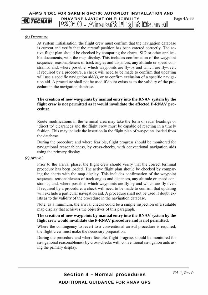
AFMS N°D01 FOR GARMIN GFC700 AUTOPILOT INSTALLATION AND RNAV/RNP NAVIGATION ELIGIBILITY
Page 4A-33
Section 4 – Normal procedures ADDITIONAL GUIDANCE FOR RNAV GPS
Ed. 1, Rev.0
(b) Departure
At system initialisation, the flight crew must confirm that the navigation database is current and verify that the aircraft position has been entered correctly. The ac-tive flight plan should be checked by comparing the charts, SID or other applica-ble documents, with the map display. This includes confirmation of the waypoint sequence, reasonableness of track angles and distances, any altitude or speed con-straints, and, where possible, which waypoints are fly-by and which are fly-over. If required by a procedure, a check will need to be made to confirm that updating will use a specific navigation aid(s), or to confirm exclusion of a specific naviga-tion aid. A procedure shall not be used if doubt exists as to the validity of the pro-cedure in the navigation database.
The creation of new waypoints by manual entry into the RNAV system by the flight crew is not permitted as it would invalidate the affected P-RNAV pro-cedure.
Route modifications in the terminal area may take the form of radar headings or ‘direct to’ clearances and the flight crew must be capable of reacting in a timely fashion. This may include the insertion in the flight plan of waypoints loaded from the database. During the procedure and where feasible, flight progress should be monitored for navigational reasonableness, by cross-checks, with conventional navigation aids using the primary display.
(c) Arrival Prior to the arrival phase, the flight crew should verify that the correct terminal procedure has been loaded. The active flight plan should be checked by compar-ing the charts with the map display. This includes confirmation of the waypoint sequence, reasonableness of track angles and distances, any altitude or speed con-straints, and, where possible, which waypoints are fly-by and which are fly-over. If required by a procedure, a check will need to be made to confirm that updating will exclude a particular navigation aid. A procedure shall not be used if doubt ex-ists as to the validity of the procedure in the navigation database. Note: as a minimum, the arrival checks could be a simple inspection of a suitable map display that achieves the objectives of this paragraph. The creation of new waypoints by manual entry into the RNAV system by the flight crew would invalidate the P-RNAV procedure and is not permitted. Where the contingency to revert to a conventional arrival procedure is required, the flight crew must make the necessary preparation. During the procedure and where feasible, flight progress should be monitored for navigational reasonableness by cross-checks with conventional navigation aids us-ing the primary display.

AFMS N°D01 FOR GARMIN GFC700 AUTOPILOT INSTALLATION AND RNAV/RNP NAVIGATION ELIGIBILITY
Page 4A-34
Section 4 – Normal procedures ADDITIONAL GUIDANCE FOR RNAV GPS
Ed. 1, Rev.0
Route modifications in the terminal area may take the form of radar headings or ‘direct to’ clearances and the flight crew must be capable of reacting in a timely fashion. Although a particular method is not mandated, any published altitude and speed constraints must be observed. In the event that either the GPS or the EGNOS signal is not available at the desti-nation, by the nature of the system, and its susceptibility to interference, there ex-ists the possibility that it will also be unavailable over a wide area. Therefore it is probable that the signal will also be unavailable at a nearby diversion aerodrome. Notwithstanding any normal operational requirements for the identification of an alternate aerodrome, where a RNAV approach is to be flown in conditions where a visual approach will not be possible; pilots should always ensure that either: 1) A different type of approach system is available at the destination, not de-
pendent on GPS data and for which the weather is forecast to be suitable to enable a landing to be made from that approach, or;
2) There is at least one alternate destination within range, where a different type of approach system is available, which is not dependent on GPS data and for which the weather is forecast to be suitable to enable a landing to be made from that approach.
9.1 APPROACH APPLICATIONS
When GPS is not approved for the selected final approach course, the message “NOT APPROVED FOR GPS” is displayed. GPS provides guidance for the approach, but the HIS must be switched to a NAV re-ceiver to fly the final course of the approach.
If certain GPS parameters (SBAS, RAIM, etc.) are not available, some
published approach procedures for the desired airport may not be dis-played in the list of available approaches.
An Approach Procedure (APPR) can be loaded at any airport that has one availa-ble, and provides guidance for non-precision and precision approaches to airports with published instrument approach procedures.
Only one approach can be loaded at a time in a flight plan. If an ap-proach is loaded when another approach is already in the active flight plan, the new approach replaces the previous approach. The route is de-fined by selection of an approach and the transition waypoints.
NOTE
NOTE
NOTE

AFMS N°D01 FOR GARMIN GFC700 AUTOPILOT INSTALLATION AND RNAV/RNP NAVIGATION ELIGIBILITY
Page 4A-35
Section 4 – Normal procedures ADDITIONAL GUIDANCE FOR RNAV GPS
Ed. 1, Rev.0
Whenever an approach is selected, the choice to either “load” or “activate” is giv-en. “Loading” adds the approach to the end of the flight plan without immediately using it for navigation guidance. This allows continued navigation via the inter-mediate waypoints in the original flight plan, but keeps the procedure available on the Active Flight Plan Page for quick activation when needed. “Activating” also adds the procedure to the end of the flight plan but immediately begins to provide guidance to the first waypoint in the approach. When selecting an approach, a “GPS” designation to the right of the procedure name indicates the procedure can be flown using the GPS receiver. Some proce-dures do not have this designation, meaning the GPS receiver can be used for supplemental navigation guidance only.
If the GPS receiver cannot be used for primary guidance, the appropri-ate navigation receiver must be used for the selected approach (e.g., VOR or ILS). The final course segment of ILS approaches, for example, must be flown by tuning the NAV receiver to the proper frequency and selecting that NAV receiver on the CDI.
The G1000 SBAS GPS allows for flying LNAV, LP, LP+V and LPV approach service levels according to the published chart. The ‘+V’ designation adds adviso-ry vertical guidance for assistance in maintaining a constant vertical glidepath similar to an ILS glideslope on approach. This guidance is displayed on the sys-tem PFD in the same location as the ILS glideslope using a magenta diamond. A sample of how the active approach service level is annunciated on the HSI is shown in the following table:
HSI Annunciation Description Example on HSI
LNAV RNAV GPS approach using published LNAV minima
Approach Service Level
- LNAV, LP, LP+V, LPV
LP (available only if SBAS
available)
RNAV GPS approach using published LP minima (downgrades to LNAV if SBAS unavailable)
LP+V (available only if SBAS
available)
RNAV GPS approach using published LP minima Advisory vertical guid-ance is provided (down-grades to LNAV if SBAS unavailable)
LPV (available only if SBAS
available)
RNAV GPS approach using published LPV minima
NOTE

AFMS N°D01 FOR GARMIN GFC700 AUTOPILOT INSTALLATION AND RNAV/RNP NAVIGATION ELIGIBILITY
Page 4A-36
Section 4 – Normal procedures ADDITIONAL GUIDANCE FOR RNAV GPS
Ed. 1, Rev.0
Before reaching the IAF, the flight crew should verify that the correct procedure has been loaded into the receiver’s route or flight plan. A comparison with the ap-proach chart should be made including the following:
a) The waypoint sequence. b) Reasonableness of the tracks and distances of the approach legs, accura cy of the inbound course and mileage of the FAS. c) Verify from the charts, map display or CDU, which waypoints are fly- by and which are fly-over. d) Check any map display to ensure the track lines actually ‘fly-over’ or ‘fly-by’ the respective waypoints in the procedure.
By the time the aircraft reaches the IAF the pilot should have completed the above and been cleared for the approach. Also, the approach must have been activated in the receiver at least by this time. Approach Applications which are classified as RNP Approach (APCH) in accord-ance with ICAO Doc 9613 Performance Based Navigation (PBN) Manual (and ICAO state Letter SP65/4-10/53) give access to minima (on an instrument ap-proach procedure) designated as:
LNAV (Lateral Navigation) This is a Non-Precision or 2D Approach with Lateral only navigation guidance provided by GNSS and an Aircraft Based Augmentation System (ABAS). Re-ceiver Autonomous Integrity Monitoring (RAIM) is a form of ABAS. Lateral guidance is linear with accuracy to within +/- 0.3 NM parallel to either side of the final approach track. LP (Localiser Performance) This is a Non-Precision or 2D Approach with Lateral only navigation guidance provided by GNSS and SBAS. The EGNOS is a form of SBAS in Europe. The lateral guidance is angular with increasing sensitivity as the aircraft continues along the final approach track; much like a localiser indication. LPV (Localiser Performance with Vertical Guidance) This is an Approach Procedure with Vertical Guidance. The Lateral and Vertical guidance is provided by GPS and SBAS. Lateral and vertical guidance are angular with increasing sensitivity as the aircraft progresses down the final approach track; much like an ILS indication. LPV approach and annunciation on HSI is available only is SBAS available.
CAUTION
Before selecting a LPV approach, make sure SBAS is indicated AC-TIVE in the GPS status box on AUX-GPS STATUS page on MFD. If DISABLED highlight the appropriate SBAS SELECTION Box un-der SBAS softkey under AUX-GPS Status Page on MFD.
Should SBAS signal be lost, augmentation is lost. It may be possible to continue with LNAV only but this is reliant on the availability of RAIM.
NOTE

AFMS N°D01 FOR GARMIN GFC700 AUTOPILOT INSTALLATION AND RNAV/RNP NAVIGATION ELIGIBILITY
Page 4A-37
Section 4 – Normal procedures ADDITIONAL GUIDANCE FOR RNAV GPS
Ed. 1, Rev.0
NOTE: The instrument approach procedures associated with RNP APCH are en-titled RNAV (GNSS) to reflect that GNSS is the primary navigation system. With the inherent onboard performance monitoring and alerting provided by GNSS, the navigation specification qualifies as RNP, however these procedures pre-date PBN, so the chart name has remained as RNAV.
Missed approach procedures Before commencing an RNAV (GNSS) missed approach, a MAP should be pos-sible without reference to GPS derived navigation so that, in the event of a loss of GPS accuracy or loss of integrity during the approach, a safe return to above Min-imum Sector Altitude can be made. This may be possible by dead reckoning (DR) navigation but where this is not possible and the MAP requires reference to terrestrial navigation aids, these must be available, tuned and correctly identified before passing the IAF and remain available throughout the approach. Reasons for a missed approach are many and if GPS information remains availa-ble for the MAP, the pilot must be able to sequence the system correctly past the MAP, in order to follow the published MAP correctly. Pilots should be fully competent in the necessary selection routines required by their own equipment, in order to transition to the MAP and preserve accurate nav-igation throughout. When GPS navigation is NOT available for the MAP, it may be necessary to re-set the display function of the HSI/CDI to disengage GPS information and regain VOR/LOC display. Pilots must be fully conversant with navigation display selec-tions in order safely to follow the MAP. Abnormal procedures for approaches As the aircraft approaches the FAF (LNAV Only, without SBAS), the receiver au-tomatically perform a final RAIM prediction for the approach. The receiver will not enter the approach mode if this RAIM prediction is negative. In this case, the approach should be discontinued. However, this RAIM check assumes availability of the full constellation and will not take account of scheduled interruptions or failures. This can lead to a success-ful RAIM prediction at this point when the RAIM function itself is not available. If RAIM is lost after passing the FAF the equipment should continue to provide navigation, where possible for five minutes, before giving a RAIM loss indication and this should be enough to complete the approach. Should RAIM detect an out of tolerance situation, a warning will be given and a missed approach should be initiated immediately.

AFMS N°D01 FOR GARMIN GFC700 AUTOPILOT INSTALLATION AND RNAV/RNP NAVIGATION ELIGIBILITY
Page 4A-38
Section 4 – Normal procedures ADDITIONAL GUIDANCE FOR RNAV GPS
Ed. 1, Rev.0
The approach should always be discontinued: • If the receiver fails to engage the correct approach mode or; • In case of Loss Of Integrity (LOI) monitoring or; • Whenever the HSI/CDI indication (or GP indication where applicable) ex-
ceeds half scale displacement or; • If a RAIM (or equivalent) warning is activated or; • If RAIM (or equivalent) function is not available and annunciated before passing
the FAF.
Page D01-16
Section 9 – Supplements - Supplement no. D01 – GARMIN GFC700 AUTOPILOT INSTALLATION AND RNAV/RNP
NAVIGATION ELIGIBILITY
Ed. 1, Rev.0
SECTION 5 – PERFORMANCE Make sure you first applied instructions reported on the basic AFM,
Section 5 Performance
According to A/C configuration refer to the basic AFM, Section 5 – Performance
Supplement D01: pages replacement instructions

Page D01-17
Section 9 – Supplements - Supplement no. D01 – GARMIN GFC700 AUTOPILOT INSTALLATION AND RNAV/RNP
NAVIGATION ELIGIBILITY
Ed. 1, Rev.0
INTENTIONALLY LEFT BLANK

Page D01-18
Section 9 – Supplements - Supplement no. D01 – GARMIN GFC700 AUTOPILOT INSTALLATION AND RNAV/RNP
NAVIGATION ELIGIBILITY
Ed. 1, Rev.0
SECTION 6 – WEIGHT AND BALANCE Make sure you first applied instructions reported on the basic AFM,
Section 6 Weight and Balance
According to A/C configuration apply following pages replacement:
Supplement D01 WEIGHT AND BALANCE
page
AFM Section 6
page 6A-11 thru 12 REPLACES 6-11 thru 12 of basic AFM, Section 6
Supplement D01: pages replacement instructions

Page D01-19
Section 9 – Supplements - Supplement no. D01 – GARMIN GFC700 AUTOPILOT INSTALLATION AND RNAV/RNP
NAVIGATION ELIGIBILITY
Ed. 1, Rev.0
INTENTIONALLY LEFT BLANK

AFMS N°D01 FOR GARMIN GFC700 AUTOPILOT INSTALLATION AND RNAV/RNP NAVIGATION ELIGIBILITY
Page 6A-11
Section 6 – Weight and balance EQUIPMENT LIST
Ed. 1, Rev. 0
EQUIPMENT LIST 5The following is a list of equipment which may be installed in the P2010. The items marked with an "X" were installed on the airplane described at the be-ginning of the list and they are included in the Basic Empty Weight. It is the owner’s responsibility to retain this equipment list and amend it to re-flect changes in equipment installed in this airplane.

AFMS N°D01 FOR GARMIN GFC700 AUTOPILOT INSTALLATION AND RNAV/RNP NAVIGATION ELIGIBILITY
Page 6A-12
Section 6 – Weight and balance EQUIPMENT LIST
Ed. 1, Rev. 0
EQUIPMENT LIST AIRCRAFT S/N_____ DATE:
REF. DESCRIPTION P/N INST WEIGHT
[kg] ARM [M]
INSTRUMENTATION
A1 GARMIN G1000 IFDS
A2 MD 302 MID Continent 6420302-1 0.73 -0.69
A3 Compass C2400L4P 0.4 -0.69
A4 Pitch trim indicator – UMA instruments N0911S0U2DR00W 0.1 -0.69
A5 Digital Clock - Davtron M800-28V-BAT 0.1 -0.69
AVIONICS & MISCELLANEOUS B1 ELT-ACK E-04 0.73 1.61
B2 Front seats GEVEN E5-01-007-T01 (LH) E5-01-008-T01 (RH)
20
(10x2) 0.50
B3 Rear seats GEVEN E5-01-007-T01 (LH) E5-01-008-T01 (RH)
20
(10x2) 1.26
B4 Fire extinguisher 13-07655 0.8 -0.18
B5 First aid kit FIA270160 0.2 0.5
B6 Torch --------- 1 -0.18
B7 Battery GILL247- 24V -19Ah G247 19.3 3.05
B8 Fuel qty sender – Electronics international P-300C 0.15 0.5
B9 ADF Receiver – RA 3502 0505.757-912 1.5 3.05
B10 DME Transceiver - King KN 63 066-01070-0001 2 3.05
GARMIN GFC700 Autopilot:
B11 Servo pitch GSA 80 011-00877-20 1.44 5.3
B12 Servo roll GSA 80 011-00877-20 1.44 2.05
B13 Servo pitch trim GSA 81 011-00878-20 1.03 5.3
LIGHTS:
B14 Nav/POS/Strobe Light SH wing - Ultragalactica Aveo AVE-WPST R/G-54G 1 0.23
B15 Rudder Nav Light – PosiStrobe CT AVE-POSW-62G 1 5.5
B16 Landing/Taxy Light - WHELEN Mod 7167400 01-0771674-00 2 -1.52
PITOT STATIC:
B17 Pitot (Heated) - Falcon Gauge 24-AN5812-1 3 0.5
LANDING GEAR ACCESSORIES
C1 Nose Landing Gear Wheel Fairing 210-4-3001-401 1.2 -1.48
C2 Main Landing Gear Wheel Fairings 210-4-1020-001-L/R 3 (1.5x2) 0.66

Page D01-20
Section 9 – Supplements - Supplement no. D01 – GARMIN GFC700 AUTOPILOT INSTALLATION AND RNAV/RNP
NAVIGATION ELIGIBILITY
Ed 1, Rev. 0
SECTION 7 – AIRFRAME AND SYSTEMS DESCRIPTION Make sure you first applied instructions reported on the basic AFM,
Section 7 Airframe and Systems Description
According to A/C configuration apply following pages replacement:
Supplement D01 AIRFRAME AND SYSTEMS DESCRIPTION
page
AFM Section 7
page
7A-8 thru 9 REPLACES 7-8 thru 9 of basic AFM, Section 7
7A-20 thru 21 REPLACES 7-20 thru 21 of basic AFM, Section 7
7A-27 REPLACES 7-27 of basic AFM, Section 7
7A-33 REPLACES 7-33 of basic AFM, Section 7
Supplement D01: pages replacement instructions

Page D01-21
Section 9 – Supplements - Supplement no. D01 – GARMIN GFC700 AUTOPILOT INSTALLATION AND RNAV/RNP
NAVIGATION ELIGIBILITY
Ed 1, Rev. 0
INTENTIONALLY LEFT BLANK

AFMS N°D01 FOR GARMIN GFC700 AUTOPILOT INSTALLATION AND RNAV/RNP NAVIGATION ELIGIBILITY
Page 7A-8
Section 7 – Airframe and Systems description FLIGHT CONTROLS
Ed. 1, Rev. 1
3 FLIGHT CONTROLS Aircraft flight controls are operated through conventional stick and rudder pedals. Longitudinal control acts through a system of push-rods and is equipped with a trim tab. a cable control circuit is confined within the cabin and it is connected to a pair of push-pull rod systems positioned in each main wing which control ailerons differen-tially. Aileron trimming is carried out on ground through a small tab positioned on left aileron. Flaps are extended via an electric servo actuator controlled by a switch on the instru-ment panel. Flaps act in continuous mode; the indicator displays three markings relat-ed to 0°, takeoff (T/O) and landing (FULL) positions. A breaker positioned on the right side of the instrument panel protects the electric circuit. The control of the stabilator trim is operated by means of both a control wheel, locat-ed between the two front seats that acts directly on the control cables, and an electri-cal actuator controlled by a switch located on the control wheel; stabilator trim posi-tion is displayed on a dedicated analogue indicator located on the LH area of the in-strument panel. Rudder Trimming device for lateral control is provided by means of an electrical ac-tuator controlled by a rocker switch located near the pitch trim wheel; the surface is con-nected to a potentiometer linked to a rudder trim indicator included in the Gar-min G1000 EIS (Engine Indication System).

AFMS N°D01 FOR GARMIN GFC700 AUTOPILOT INSTALLATION AND RNAV/RNP NAVIGATION ELIGIBILITY
Page 7A-9
Section 7 – Airframe and Systems description INSTRUMENTAL PANEL
Ed. 1, Rev. 0
4 INSTRUMENT PANEL The instrument panel is divided in three areas:
• The left area holds Garmin G1000 PFD, a chronometer and the pitch trim indicator; • The Central area holds the standby unit for PFI parameters, MD 302 suite, and the
ELT button. • The right area holds Garmin G1000 MFD with dedicated AP control buttons and
breaker panel; • The lower-LH portion of the instrument panel holds:
Ignition key; Master and Generator switches; Emergency fuel pump; Avionic Master switch; AP Master switch Trim Disconnect switch
• The lower-Central portion of the instrument panel holds: Fuel selector valve. Flap Control
• The lower-RH portion of the instrument panel holds: Pocket
Fig. 7-8. INSTRUMENT PANEL

AFMS N°D01 FOR GARMIN GFC700 AUTOPILOT INSTALLATION AND RNAV/RNP NAVIGATION ELIGIBILITY
Page 7A-20
Section 7 – Airframe and Systems description ELECTRICAL SYSTEM
Ed. 1, Rev. 0
9 ELECTRICAL SYSTEM Primary DC power is provided by an external alternator with a 28 VDC output, rated of 70 Amps @ 2700 rpm. During normal operations, it recharges the bat-tery. Secondary DC power is provided by a lead type battery (GILL G-247) which provides the energy necessary for feeding the essential electrical loads in the event of an alternator failure. The switch between the energy sources is automatic and no action is required in order to activate the alternate energy source. For ground maintenance and/or starting, an external power socket is provided. The alternator and battery are connected to the battery bus in order to provide energy for the electric equipment. Each electrically fed instrument is connected to a dedicated circuit breaker which protects the cable from the battery bus to the associated electric equip-ment.
WARNING
If the Ignition is in the position L, R, or BOTH, an accidental movement of the propeller may start the engine with possible danger for bystanders.
In the following figure is presented the electrical system architecture.

AFMS N°D01 FOR GARMIN GFC700 AUTOPILOT INSTALLATION AND RNAV/RNP NAVIGATION ELIGIBILITY
Page 7A-21
Section 7 – Airframe and Systems description ELECTRICAL SYSTEM
Ed. 1, Rev. 0
FIG.7-15. ELECTRICAL SYSTEM ARCHITECTURE
12.3 STALL WARNING SYSTEM The aircraft is equipped with a stall warning system consisting of a sensor locat-ed on the right wing leading edge connected to a warning horn located near the instrument panel.

AFMS N°D01 FOR GARMIN GFC700 AUTOPILOT INSTALLATION AND RNAV/RNP NAVIGATION ELIGIBILITY
Page 7A-27
Ed. 1Rev 0 Section 7 – Airframe and Systems description
LIGHTS
11.2 INTERNAL LIGHTS On the cabin ceiling are located four map lights, two in the front area (pilot) and two in the rear area (passengers). In the central area of the cabin ceiling is located a spot light used to illuminate the pedestal during night flight operations. All ceiling lights are dimmable by a dedicat-ed dimmer.
FIG.7-18. CABIN CEILING LIGHTS LAYOUT
The instrument panel can be illuminated by 8 incandescence light strips, all dimma-ble.
FIG.7-19. INSTRUMENT PANEL LIGHTS LAYOUT
FWD
From mid MAP light (ceiling)

AFMS N°D01 FOR GARMIN GFC700 AUTOPILOT INSTALLATION AND RNAV/RNP NAVIGATION ELIGIBILITY
Page 7A-33
Ed. 1Rev 0 Section 7 – Airframe and Systems description
PLACARDS
ELT unit position placard:
Breaker Panel placards:

AFMS N°D01 FOR GARMIN GFC700 AUTOPILOT INSTALLATION AND RNAV/RNP NAVIGATION ELIGIBILITY
Page 7A-33
Ed. 1Rev 0 Section 7 – Airframe and Systems description
PLACARDS

Page D01-22
Ed. 1Rev 0 Section 9 – Supplements -
Supplement no. D01 – GARMIN GFC700 AUTOPILOT INSTALLATION AND RNAV/RNP NAVIGATION ELIGIBILITY
SECTION 8 – GROUND HANDLING & SERVICE Make sure you first applied instructions reported on the basic AFM,
Section 8 Ground Handling & Service
According to A/C configuration refer to the basic AFM, Section 8 – Ground Handling & Service
Supplement D01: pages replacement instructions

Page D01-23
Ed. 1Rev 0 Section 9 – Supplements -
Supplement no. D01 – GARMIN GFC700 AUTOPILOT INSTALLATION AND RNAV/RNP NAVIGATION ELIGIBILITY
INTENTIONALLY LEFT BLANK

Page D02-1
Section 9 – Supplements
Supplement no. D02 –Variable pitch propeller
2nd Edition, Rev. 0
SUPPLEMENT NO. D02
AFMS FOR VARIABLE PITCH PROPELLER EQUIPPED AIRPLANES
Record of Revisions
Rev Revised page
Description of Revision
Tecnam Approval EASA Approval or Under DOA
Privileges DO OoA HDO
0 – First Issue D.Ronca M.Oliva M. Oliva
List of Effective Pages
Page Page Revision Cover Pages D02-1 thru 17 Rev 0
Section 1 V1-6 Rev 0 Section 2 V2-7 Rev 0 Section 2 V2-9, 10 Rev 0 Section 3 V3-14 Rev 0 Section 3 V3-18 thru 19 Rev 0 Section 4 V4-7 Rev 0 Section 4 V4-15 Rev 0 Section 4 V4-19 thru 26 Rev 0 Section 5 5-1 thru 16 Rev 0 Section 7 V7-10 thru 11 Rev 0 Section 7 V7-16 Rev 0 Section 7 V7-27 Rev 0 Section 7 V7-36 Rev 0

Page D02-2
Section 9 – Supplements
Supplement no. D02 –Variable pitch propeller
2nd Edition, Rev. 0
INTRODUCTION
The information contained herein supplements or supersedes the basic Aircraft Flight Manual: detailed instructions are provided to allow the owner for replac-ing the AFM pages containing information amended as per MT variable pitch propeller in subject.
It is the owner’s responsibility to replace the mentioned pages in accordance with the instructions herein addressed section by section.

Page D02-3
Section 9 – Supplements
Supplement no. D02 –Variable pitch propeller
2nd Edition, Rev. 0
SECTION 1 – GENERAL
Make sure you first applied instructions reported on the basic AFM, Section 1 General
Apply following pages replacement:
Supplement D02 – GENERAL page
AFM Section 1 page
1-6 REPLACES Page 1-6 of AFM, Section 1
Supplement D02: pages replacement instructions

Page D02-4
Section 9 – Supplements
Supplement no. D02 –Variable pitch propeller
2nd Edition, Rev. 0
INTENTIONALLY LEFT BLANK

AFMS N°D02 FOR VARIABLE PITCH PROPELLER EQUIPPED AIRPLANES
Page V1-6
Section 1 – General
GENERAL FEATURES
2nd Edition, Rev. 0
5. ENGINE
Manufacturer …………………………… Lycoming Engines Model …………………………………... IO-360-M1A Type Certificate ………………………... EASA TCDS no. IM.E.032 Engine type …………………………….. Fuel injected (IO), direct drive, four cylinder
horizontally opposed, air cooled with down exhaust outlets.
Maximum power ……. Maximum continuous power …………...
134.0 kW (180hp) @ 2700 rpm 129.2 kW (173.3hp) @ 2600 rpm
6. PROPELLERManufacturer ………………………….. MT PropellerModel …………………………………. MTV-15-B/193-52Type Certificate ……………………….. EASA TCDS no. P.098Blades/hub …………………………….. wood/composite 2-blades – aluminum hubDiameter ………………………………. 1930 mm (76 in) (no reduction is permitted)Type …………………………………… Variable pitch
GovernorManufacturer ………………………….. MT PropellerModel …………………………………. P-860-23:Type ……………………….. Hydraulic

Page D02-5
Section 9 – Supplements
Supplement no. D02 – Variable pitch propeller
2nd Edition, Rev. 0
INTENTIONALLY LEFT BLANK

Page D02-6
Section 9 – Supplements
Supplement no. D02 – Variable pitch propeller
GENERAL FEATURES
2nd Edition, Rev. 0
SECTION 2 – LIMITATIONS
Make sure you first applied instructions reported on the basic AFM, Section 2 Limitations
Apply following pages replacement:
Supplement D02 – LIMITATIONS page
AFM Section 2 page
V2-7 REPLACES Page 2-7 of AFM, Section 2
V2-9 REPLACES Page 2-9 of AFM, Section 2
V2-10 REPLACES Page 2-10 of AFM, Section 2
Supplement D02: pages replacement instructions

Page D02-7
Section 9 – Supplements
Supplement no. D02 – Variable pitch propeller
2nd Edition, Rev. 0
INTENTIONALLY LEFT BLANK

AFMS N°D02 FOR VARIABLE PITCH PROPELLER EQUIPPED AIRPLANES
Page V2-7
Section 9 – Supplements
Powerplant limitations
2nd Edition, Rev. 0
4. POWERPLANT LIMITATIONS
Following table reports the operating limitations the installed engine: ENGINE MANUFACTURER: Lycoming Engines ENGINE MODEL: IO-360-M1A MAXIMUM POWER:
Max Power (hp)
Max rpm. Prop. rpm
Max. T.O. 180 2700
Max. Cont. 173.3 2600
Temperatures: Max CHT ……………………………………….. 500° F (260° C) Max Oil …………………………………………. 245° F (118° C) Oil Pressure: Minimum Idling ………………………………… 25 psi (1.7 Bar) Minimum Normal ………………………………. 55 psi (3.8 Bar)
Maximum Normal ……………………………… 95 psi (6.5 Bar) Starting, Warm-up, taxi and take-off (Max) …… 115 psi (7.9 Bar)
Fuel pressure: - At Inlet to fuel injector:
Minimum .............................................................. 14 psi (0.96 Bar) Maximum ............................................................. 35 psi (2.41 Bar)

AFMS N°D02 FOR VARIABLE PITCH PROPELLER EQUIPPED AIRPLANES
Page V2-9
2nd Edition Rev.0 Section 2 – Limitations
PAINT, PROPELLER, MAX ALTITUDE AND OAT
CAUTION
At altitudes above 10000 ft (3048 m) up to and including 12000 ft (3658 m), flight crew is recommended to use supplemental oxygen.
8. AMBIENT TEMPERATURE
Ambient temperature: from -25°C to +50°C.
WARNING
Flight in expected and/or known icing conditions is forbidden.
5. PAINTTo ensure that the temperature of the composite structure does not exceed limits,the outer surface of the aeroplane must be painted with white paint, except for areasof registration marks, placards, and ornament.Refer to Aircraft Maintenance Manual (AMM), ATA Chapter 4 and 51, for specificpaint requirements.
6. PROPELLER
MANUFACTURER: .…….. MT PropellerMODEL: …………….……. MTV 15B/193-52TYPE: .……………….…… wood/composite 2-blade, variable pitchDIAMETER: ……………... 1930 mm (76 in) (no reduction is permitted)
7. MAXIMUM OPERATING ALTITUDE
Maximum operating altitude is 12000 ft (3658 m) MSL.

AFMS N°D02 FOR VARIABLE PITCH PROPELLER EQUIPPED AIRPLANES
Page V2-10
2nd Edition Rev.0 Section 2 – Limitations
POWERPLANT AND OTHER INSTRUMENT MARKINGS
4. POWERPLANT INSTRUMENT MARKINGS
Powerplant instrument markings and their colour code significance are shown below:
INSTRUMENT
RED ARC Minimum
limit
WHITE ARC Advisory
GREEN ARC Safe
operation
YELLOW ARC Caution
RED ARC Maximum
limit
PROPELLER RPM / / 950-2600 0-950
2600-2700 2700 (line)
OIL TEMP. °F / / 140-245 0 - 140 245 - 255
CHT °F / 435 (line) 150-475 0 – 150 475-500
500-510
EGT °F / 1000-1500 / 1375 (line) 1500-1550
OIL PRESS psi 0-25 / 55-95 25 - 55
95-115 115 - 125
FUEL PRESS psi 0-14 / 14-35 / 35 - 40
FUEL QTY litres 0
/ 0-115
/ / gal 0 0-30,4
FUEL FLOW l/hr
/ 0-75
/ / / gal/hr 0-20
5. OTHER INSTRUMENT MARKINGS
INSTRUMENT RED ARC
Minimum limit GREEN ARC
Safe operation YELLOW ARC
Caution RED ARC
Maximum limit
Voltmeter 20-21 Volt 24–30 Volt 21–24 Volt 30-31

Page D02-8
Section 9 – Supplements
Supplement no. D02 – Variable pitch propeller
2nd Edition, Rev. 0
INTENTIONALLY LEFT BLANK

Page D02-9
Section 9 – Supplements
Supplement no. D02 – Variable pitch propeller
2nd Edition, Rev. 0
SECTION 3 – EMERGENCY PROCEDURES
Make sure you first applied instructions reported on the basic AFM, Section 3 Emergency Procedures
Apply following pages replacement:
Supplement D02 – Emergency Procedures page
AFM Section 3 page
V3-14 REPLACES Page 3-14 of AFM, Section 3
V3-18 thru 19 REPLACES Page 3-18 thru 19 of AFM, Section 3
Supplement D02: pages replacement instructions

Page D02-10
Section 9 – Supplements
Supplement no. D02 – Variable pitch propeller
2nd Edition, Rev. 0
INTENTIONALLY LEFT BLANK

AFMS N°D02 FOR VARIABLE PITCH PROPELLER EQUIPPED AIRPLANES
Page V3-14
Section 3 – Emergency procedures
POWERPLANT EMERGENCIES
2nd Edition, Rev. 0
6.3. PROPELLER OVERSPEED
In case of propeller overspeed in flight, apply following procedure:
1. Throttle Lever ……………. REDUCE power 2. Propeller Lever ……………. Decrease RPM 3. Mixture Lever ……………. As required 4. RPM indicator .…………… CHECK
If it is not possible to decrease propeller rpm, land as soon as possible applying Forced landing procedure. (See Para 11)
CAUTION
Maximum propeller rpm exceedance may cause engine components damage. Monitor engine RPM; overspeed shall be prevented by retarding propeller lever.
6.4. IRREGULAR RPM
1. Fuel pump: …………………………………ON 2. Fuel quantity and pressure indicators: …..…CHECK 3. If necessary: ……………………………….. SWITCH TANK
If engine continues to run irregularly
Land as soon as possible.

AFMS N°D02 FOR VARIABLE PITCH PROPELLER EQUIPPED AIRPLANES
Page V3-18
Section 3 – Emergency procedures
POWERPLANT EMERGENCIES
2nd Edition, Rev.0
6.10. DEFECTIVE ENGINE CONTROLS
Defective Mixture Control Cable
1. Maintain altitude to the nearest arfield 2. During descent, check engine behaviour to a higher power setting. A lean
mixture can lead to engine roughness and loss of power. Landing approach must be planned accordingly.
WARNING
Go-around may then be impossible.
Defective Throttle Control Cable If power is sufficient to continue flight:
1. Approach nearest airfield, control engine power with Propeller lever 2. Perform landing with shut-down engine applying Forced landing proce-
dure. (See Para 11) If power is not sufficient to continue flight:
1. Carry out Forced landing procedure. (See Para 11)
Defective Propeller Lever Control Cable If power is sufficient to continue flight:
1. Approach nearest airfield, control engine power with throttle 2. Perform normal landing.
WARNING
Go-around may then be impossible.
If power is not sufficient to continue flight: 1. Carry out Forced landing procedure. (See Para 11)

AFMS N°D02 FOR VARIABLE PITCH PROPELLER EQUIPPED AIRPLANES
Page V3-19
Section 3 – Emergency procedures
POWERPLANT EMERGENCIES
2nd Edition, Rev.0
7. INFLIGHT ENGINE RESTART
7.1. PROPELLER WINDMILLING
WARNING
In case of engine shutdown, propeller will keep windmilling and will not stop, preventing the use of ignition key. Engine inflight restart must be performed without using ignition key with propeller wind-milling in order to avoid possible engine damages. Typical indication of a potential engine shutdown, with windmilling propeller, will be RPM running sub-idle below 600-500 RPM, to be confirmed by other engine instrument (OIL Pressure, CHT, EGT running down abnormally). Inflight engine restart may be performed during 1g flight anywhere within the normal operating envelope of the airplane.
1. Master switch ……………………………… Check ON 2. Fuel pump …………………………………. ON 3. Fuel quantity indicator …………………….. CHECK 4. Fuel Selector ………………………………. SWITCH TANK 5. Throttle Lever …………………………….. Minimum 1cm. above IDLE 6. Propeller Lever…………………………….. Full forward 7. Mixture …………………………………… FULL rich 8. Throttle lever ……………………………… SET as required
In case of unsuccessful engine restart:
Land as soon as possible applying Forced landing procedure. (See Para 11 Erro-
re. L'origine riferimento non è stata trovata.)
In case of successful engine restart:
Land as soon as possible
CAUTION
After engine restart, if practical, moderate propeller rpm to al-low the temperatures for stabilizing in the green arcs.

Page D02-11
Section 9 – Supplements
Supplement no. D02 – Variable pitch propeller
2nd Edition, Rev.0
INTENTIONALLY LEFT BLANK

Page D02-12
Section 9 – Supplements
Supplement no. D02 – Variable pitch propeller
2nd Edition, Rev.0
SECTION 4 – NORMAL PROCEDURES
Make sure you first applied instructions reported on the basic AFM, Section 4 Normal Procedures
Apply following pages replacement:
Supplement D02 – Normal Procedures page
AFM Section 4 page
V4-7 REPLACES Page 4-7 of AFM, Section 4
V4-15 REPLACES Page4-15 of AFM, Section 4
V4-19 thru 26 REPLACES Page4-19 thru 26 of AFM, Section 4
Supplement D02: pages replacement instructions

Page D02-13
Section 9 – Supplements
Supplement no. D02 – Variable pitch propeller
2nd Edition, Rev.0
INTENTIONALLY LEFT BLANK

AFMS N°D02 FOR VARIABLE PITCH PROPELLER EQUIPPED AIRPLANES
Page – V4-7
Section 4 – Normal procedures
AIRSPEED FOR NORMAL OPERATIONS
2nd Edition, Rev. 0
3. AIRSPEEDS FOR NORMAL OPERATIONS
The following airspeeds are those which are significant for normal operations.
FLAPS 1160kg (2557lbs)
Rotation Speed (VR) T/O 60 KIAS
Best Angle-of-Climb Speed (VX) 0° 75 KIAS
Best Rate-of-Climb speed (VY) 0° 82 KIAS
Flaps (VFE) T/O & LAND 91 KIAS
No flaps approach 0° 80 KIAS
Approach speed T/O 75 KIAS
Final Approach Speed FULL 70 KIAS
Manoeuvring speed (VA) 0° 120 KIAS
Vglide 0° 84 KIAS
Never Exceed Speed (VNE) 0° 166 KIAS

AFMS N°D02 FOR VARIABLE PITCH PROPELLER EQUIPPED AIRPLANES
Page – V4-15
Section 4 – Normal procedures
CHECKLISTS
2nd Edition, Rev. 0
5. CHECKLISTS
5.1. BEFORE STARTING ENGINE (AFTER PREFLIGHT INSPECTION)
1. Seat position and safety belts: adjust 2. Flight controls: operate full stroke checking for movement smoothness, free of
play and friction. 3. Parking brake: engage 4. Throttle friction: adjust 5. Throttle: IDLE 6. Propeller Lever: HIGH RPM 7. Mixture control Lever: LEAN 8. Circuit Breakers: check all IN 9. Master switch: ON, wait PFD turn on, Check ALT OUT caution ON, Check LOW
FP and LOW OP warning ON 10. Only before the first flight of the day:
Standby Instrument: Check no red crosses displayed. a. Press and hold the control knob (approx. 2 sec) b. Rotate the knob selecting “INFO>” page then press it c. Select “BATTERY INFO” page then press the knob d. Check “CHARGE (%)” to be more than 80%, then exit menu
11. Avionic Master switch: ON, wait MFD turn on, check instruments, check Voltage on Main and Essential Buses.
12. Fuel quantity: compare the fuel quantity indicators information with fuel quantity visually checked into the tanks (see Pre-flight inspection – External inspection), then update the Garmin fuel content in the totalizer accordingly
The totalizer function available on Garmin Engine page allows input only up to 230lts (maximum usable fuel). Initial Fuel indication on totalizer must be correct-ed manually (as it does not use the aircraft fuel quantity indicators as input). Once correctly initialized, fuel consumption on totalizer is very precise as it take instantaneous fuel flow for computation.
13. Electric fuel pump: ON (check for audible pump noise and increase of fuel pressure) 14. Warning “LOW FUEL PRESSURE”: extinguished 15. Electric fuel pump: OFF 16. Flap control: cycle fully extended and then set to T/O 17. Pitch Trim: cycle fully up and down, then set to NEUTRAL 18. Rudder trim: cycle full right and left, then set to NEUTRAL
WARNING
Pitch trim position other than in neutral position would affect take off performance and take off rotation execution at the correct VR.
19. Nav & Strobe lights: ON
In absence of RH seat occupant: fasten seat belts around the seat in order to prevent any interference with the aeroplane flight control operation and with rapid egress in an emergency.
20. Doors: Closed and locked
NOTE
NOTE

AFMS N°D02 FOR VARIABLE PITCH PROPELLER EQUIPPED AIRPLANES
Page V4-19
Section 4 – Normal procedures
CHECKLISTS
2nd Edition, Rev. 0
5.5. BEFORE TAKEOFF
1. Parking brake: brake pedal press, ON 2. Engine instruments: Check within limits 3. ALT OUT caution: OFF (check) 4. Electric Fuel pump: ON 5. Fuel selector valve: select the fullest tank 6. Fuel pressure: check 7. Mixture: FULL RICH
For 5000ft density altitude and above, or high ambient temperatures, a FULL RICH mixture may cause rough running of the engine or a loss of performance. The mixture may be adjusted to obtain smooth engine operations.
8. Throttle: set 1500 RPM a. Alternate Air check: Alternate Air: PULL (Check drop 50-100 RPM) b. Mixture check: Mixture: reduce EGT: check increase FF: check decrease Mixture: FULL RICH
9. Throttle: 2100 RPM 10. Propeller Lever:
Pull back until a drop of max. 500 RPM is reached then high RPM
Cycle 3 times
11. Magneto Check: L – BOTH – R – BOTH Max RPM drop: 175 RPM Max. difference: 50 RPM
12. Throttle: Idle 13. Flaps: check T/O 14. Pitch and Rudder trim: check neutral 15. Flight controls: check free 16. Seat belts: check fastened 17. Doors: check closed and locked 18. Parking brake: Release 19. Landing light: ON as required 20. XPDR: ON
NOTE

AFMS N°D02 FOR VARIABLE PITCH PROPELLER EQUIPPED AIRPLANES
Page V4-20
Section 4 – Normal procedures
CHECKLISTS
2nd Edition, Rev. 0
5.6. TAKEOFF
For 5000ft density altitude and above, or high ambient temperatures, a FULL RICH mixture may cause rough running of the engine or a loss of performance. The mixture may be ad-justed to obtain smooth engine operations. Lean to maximum RPM at Full Throttle prior to take-off where airports are at 5000ft density altitude or higher. During climb, a rough method of correctly leaning is to slowly reduce mixture lever until an increase of appr.ly 50-100 RPM is noticed at constant IAS or EGT reaches 1375°F mark.
1. Pitot HEAT: ON if required 2. Fuel pump: ON 3. Brakes: apply
4. Throttle: FULL and check approximately 2680 20 RPM
WARNING
Engine proper performance at full throttle shall be checked early in the ground roll in order to abandon take-off if necessary. A rough engine, sluggish RPM increase or failure to reach take-off RPM are reasons for abandoning the take-off. If the engine oil is cold, an oil pressure in the yellow sec-tor is permissible.
5. Engine instruments: check parameters within the limits 6. Brakes: Release 7. Rotation speed VR: 60 KIAS 8. Airspeed: 67 KIAS
Above a safe height: 9. Propeller lever: 2600 RPM 10. Landing lights: OFF
NOTE

AFMS N°D02 FOR VARIABLE PITCH PROPELLER EQUIPPED AIRPLANES
Page V4-21
Section 4 – Normal procedures
CHECKLISTS
2nd Edition, Rev. 0
5.7. CLIMB
Due to position of fuel sensors, during climb fuel gauges in cockpit will indicate a fuel quantity slightly lower than the real amount. Regaining level flight will immediately restore correct indications.
For 5000ft density altitude and above, or high ambient temperatures, a FULL RICH mixture may cause rough running of the engine or a loss of performance. The mixture may be adjusted to obtain smooth engine operations. Lean to maximum RPM at Full Throttle prior to take-off where airports are at 5000ft density altitude or higher. During climb, a rough method of correctly leaning is to slowly reduce mixture lever un-til an increase of appr.ly 50-100 RPM is noticed at constant IAS or EGT reaches 1375°F mark.
1. Flaps: UP (minimum speed 73 KIAS)
Expect to adjust pitch trim (pitch up) when retracting flaps after take-off
2. Establish climb Vy: 82 KIAS 3. Electrical fuel pump: OFF 4. Fuel pressure: check within limits 5. Throttle: FULL 6. MIXTURE: RICH, above 5000ft keep EGT constant 7. Engine instruments: in the GREEN
If the fuel pressure warning light illuminates, or the fuel pressure indication is below green arc, the electrical fuel pump must be switched ON.
NOTE
NOTE
NOTE
NOTE

AFMS N°D02 FOR VARIABLE PITCH PROPELLER EQUIPPED AIRPLANES
Page V4-22
Section 4 – Normal procedures
CHECKLISTS
2nd Edition, Rev. 0
5.8. CRUISE
1. Power: set performance as required, refer to table in section 5 of AFM 2. Propeller lever: 1800-2400 RPM 3. Fuel tank selector: as required to maintain symmetric balance 4. Mixture: set in accordance with following para 5.9
To optimize engine life, the cylinder head temperature (CHT) should lie between 150°F and 400°F in continuous operation, and not rise above 435°F in fast cruise.
Monitor and manually compensate asymmetrical fuel consumption by switching fuel selector valve. Switch ON the electric fuel pump prior to swap the fuel feeding from one tank to another.
5.9. MIXTURE ADJUSTMENT RECOMMENDATION
CAUTION
The maximum permissible cylinder head temperature (500 °F) must never be ex-ceeded. The mixture control lever should always be moved slowly. Before selecting a higher power setting the mixture control lever should, on each occasion, be moved slowly to fully RICH before throttle adjustment. Care should always be taken that the cylinders do not cool down too quickly. The cooling rate should not exceed 50 °F per minute.
For maximum service life cylinder head temperature should be kept below 475 °F (high performance cruise) and below 435 °F (for economy cruise).
Best Cruise Economy Mixture The best economy mixture setting may only be used up to a power setting of 75 %. In order to obtain the lowest specific fuel consumption at a particular power setting, proceed as follows:
- Slowly pull the mixture control lever back towards LEAN until the engine starts to run rough-ly.
- Then push the mixture control lever forward just far enough to restore smooth running. At the same time the exhaust gas temperature (EGT) should reach a maximum.
Best Cruise Power Mixture The mixture can be set for maximum performance at all power settings:
- The mixture should first be set as for best economy. - The mixture should then be enriched until the exhaust gas temperature is approximately
100°F lower. This mixture setting produces the maximum performance for a given manifold pressure and is mainly used for high power settings (approximately 75 %).
NOTE
NOTE
NOTE
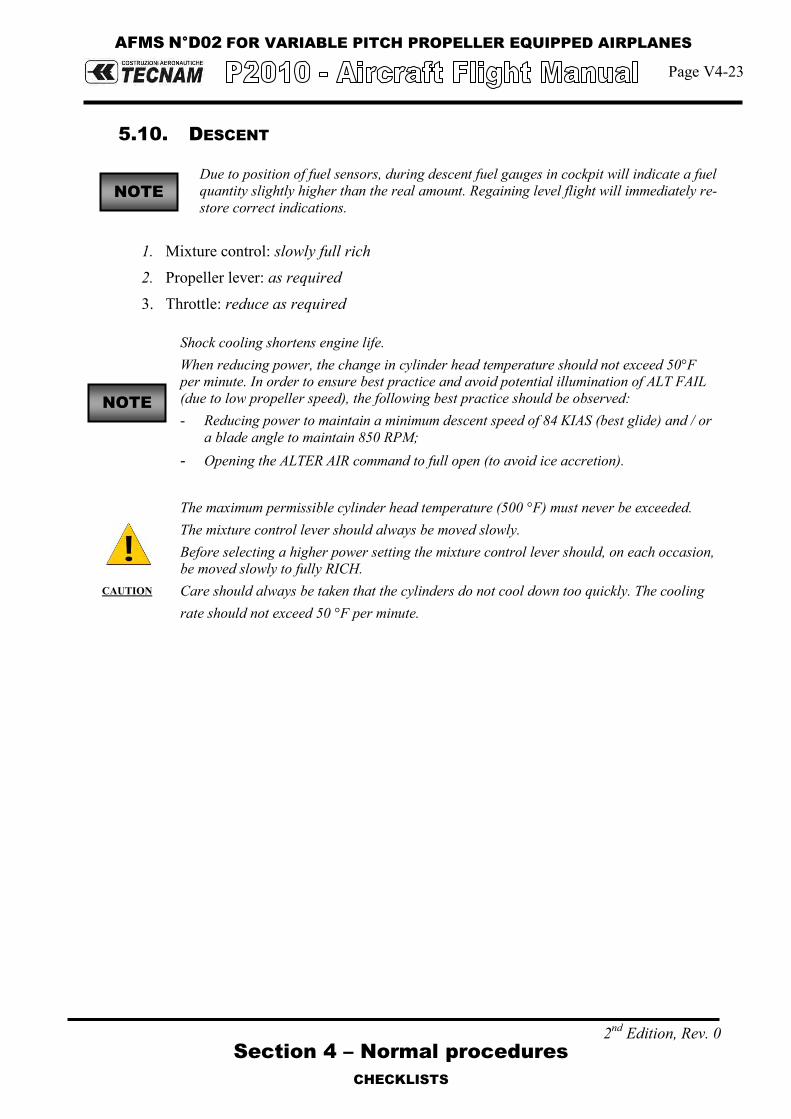
AFMS N°D02 FOR VARIABLE PITCH PROPELLER EQUIPPED AIRPLANES
Page V4-23
Section 4 – Normal procedures
CHECKLISTS
2nd Edition, Rev. 0
5.10. DESCENT
Due to position of fuel sensors, during descent fuel gauges in cockpit will indicate a fuel quantity slightly higher than the real amount. Regaining level flight will immediately re-store correct indications.
1. Mixture control: slowly full rich 2. Propeller lever: as required 3. Throttle: reduce as required
Shock cooling shortens engine life. When reducing power, the change in cylinder head temperature should not exceed 50°F per minute. In order to ensure best practice and avoid potential illumination of ALT FAIL (due to low propeller speed), the following best practice should be observed: - Reducing power to maintain a minimum descent speed of 84 KIAS (best glide) and / or
a blade angle to maintain 850 RPM; - Opening the ALTER AIR command to full open (to avoid ice accretion).
CAUTION
The maximum permissible cylinder head temperature (500 °F) must never be exceeded. The mixture control lever should always be moved slowly. Before selecting a higher power setting the mixture control lever should, on each occasion, be moved slowly to fully RICH. Care should always be taken that the cylinders do not cool down too quickly. The cooling rate should not exceed 50 °F per minute.
NOTE
NOTE

AFMS N°D02 FOR VARIABLE PITCH PROPELLER EQUIPPED AIRPLANES
Page V4-24
Section 4 – Normal procedures
CHECKLISTS
2nd Edition, Rev. 0
5.11. BEFORE LANDING
1. Electric fuel pump: ON 2. Fuel valve: select the fullest tank 3. Landing Light: ON On downwind, leg abeam touch down point: 4. Flaps: set T/O (below 90KIAS)
Expect to adjust pitch trim (pitch down) when extending flaps to T/O or LAND
5. Approach speed: set On final leg, before landing: 6. Mixture control lever: RICH 7. Propeller Lever: HIGH RPM 8. Flaps: LAND 9. Final Approach Speed: set 10. Optimal touchdown speed: 60 KIAS
CAUTION
In conditions such as (e.g.) strong wind, danger of windshear or turbulence a higher approach speed shall be selected..
5.12. BALKED LANDING/MISSED APPROACH
1. Throttle: FULL 2. Speed: keep over 80 KIAS, climb to VY or VX as applicable 3. Flaps position: T/O Above a safe height: 4. Propeller lever: 2600 RPM 5. Landing lights: OFF
5.13. GO-AROUND
1. Throttle: FULL 2. Speed: keep over 80 KIAS, climb to VY or VX as applicable 3. Flaps position: T/O
5.14. AFTER LANDING
1. Throttle: Idle 2. Brakes: apply 3. Pitot heat: OFF (if ON) 4. Flaps: UP 5. Electric Fuel Pump: OFF 6. XPDR: OFF 7. Landing light: OFF
NOTE

AFMS N°D02 FOR VARIABLE PITCH PROPELLER EQUIPPED AIRPLANES
Page V4-25
Section 4 – Normal procedures
CHECKLISTS
2nd Edition, Rev. 0
5.15. ENGINE SHUT DOWN
1. Parking brake: set 2. Keep engine running at 1200 propeller rpm for about one minute in order to
reduce latent heat. 3. Avionic equipment: OFF 4. Throttle: idle 5. Magnetos: Check OFF – BOTH 6. Mixture: closed 7. Ignition key: OFF, key extracted 8. Strobe light: OFF 9. Avionic Master: OFF 10. Master & Generator switches: OFF 11. Fuel selector valve: OFF
WARNING
For safety, verify propeller is fully stopped before any other action.
CAUTION
Instruct passenger to fully open RH door and depart, avoiding contact with wheels and sharp wing control surfaces edges.
5.16. POSTFLIGHT CHECKS
1. Flight controls: lock by means of seat belts 2. Wheel chocks and wing mooring lines: Set 3. Parking brake: Release 4. Doors: Close and lock 5. Protection plugs: set over pitot tube, stall warning, static ports

AFMS N°D02 FOR VARIABLE PITCH PROPELLER EQUIPPED AIRPLANES
Page V4-26
Section 4 – Normal procedures
CHECKLISTS
2nd Edition, Rev. 0
5.17. FLIGHT IN RAIN
Performance deteriorates in rain; this applies particularly to take-off distance and maximum Horizontal speed. The effect on flight characteristics is minimal.
5.18. REFUELLING
Before refuelling, the airplane must be connected to electrical ground.
5.19. FLIGHT AT HIGH ALTITUDE
At high altitudes the provision of oxygen for the occupant is necessary. Legal requirements for the provision of oxygen should be adhered to (see para 2.9).

Page D02-14
Section 9 – Supplements
Supplement no. D02 – Variable pitch propeller
2nd Edition, Rev. 0
SECTION 5 – PERFORMANCES
Supplement D02- Performances pages replace basic AFM Section 5 as whole
Supplement D02: pages replacement instructions

Page D02-15
Section 9 – Supplements
Supplement no. D02 – Variable pitch propeller
2nd Edition, Rev. 0
INTENTIONALLY LEFT BLANK

AFMS N°D02 FOR VARIABLE PITCH PROPELLER EQUIPPED AIRPLANES
Page V5 - 1
Section 5 – Performances
INDEX
2nd Edition, Rev. 0
SECTION 5 – PERFORMANCE
INDEX
1. Introduction .......................................................... 2
2. Use of Performance Charts .................................. 2
3. Airspeed Indicator System Calibration ................ 3
4. ICAO Standard Atmosphere .................................. 5
5. Stall speed ............................................................ 6
6. Crosswind ............................................................. 7
7. Take-Off performances ......................................... 8
8. Take-off Rate of Climb ........................................ 11
9. En-Route Rate of Climb ....................................... 12
10. Cruise Performance ............................................ 13
11. Landing performances ........................................ 17
12. Balked Landing Performance ............................. 18
13. Noise Data .......................................................... 19

AFMS N°D02 FOR VARIABLE PITCH PROPELLER EQUIPPED AIRPLANES
Page V5 - 2
Section 5 - Performances
INTRODUCTION
2nd Edition, Rev. 0
1. INTRODUCTION
This section provides all necessary data for an accurate and comprehensive plan-ning of flight activity from takeoff to landing.
Data reported in graphs and/or in tables were determined using: “Flight Test Data” under conditions prescribed by EASA CS-23 regulation aircraft and engine in good condition average piloting techniques Each graph or table was determined according to ICAO Standard Atmosphere (ISA - s.l.); evaluations of the impact on performances were carried out by theoret-ical means for:
Airspeed External temperature Altitude Weight Runway type and condition
2. USE OF PERFORMANCE CHARTS
Performances data are presented in tabular or graphical form to illustrate the effect of different variables such as altitude, temperature and weight. Given information is sufficient to plan the mission with required precision and safety.
Additional information is provided for each table or graph.

AFMS N°D02 FOR VARIABLE PITCH PROPELLER EQUIPPED AIRPLANES
Page V5 - 3
Section 5 - Performances
AIRSPEED INDICATOR SYSTEM CALIBRATION
2nd Edition, Rev. 0
3. AIRSPEED INDICATOR SYSTEM CALIBRATION
Normal Static Source
Graph shows calibrated airspeed VIAS as a function of indicated airspeed VCAS.
50
60
70
80
90
100
110
120
130
140
150
160
170
50 60 70 80 90 100 110 120 130 140 150 160
Ind
icat
ed
Air
spe
ed
[K
IAS]
Calibrated Airspeed [KCAS]
Airspeed Indication System Calibration
Flap UP
Flap T/O
Flap LN
Fig. 5-1. Calibrated vs Indicated Airspeed
Example:
Given Find
KIAS 75.0
Flap: UP KCAS 74.7
Indicated airspeed assumes 0 as an instrument error NOTE

AFMS N°D02 FOR VARIABLE PITCH PROPELLER EQUIPPED AIRPLANES
Page V5 - 4
Section 5 - Performances
AIRSPEED INDICATOR SYSTEM CALIBRATION
2nd Edition, Rev. 0
Alternate Static Source
Alternate Static Air Open Vents Open Vents and Hot Air Open
IAS [kn]
HP [ft]
IAS [kn]
HP [ft]
IAS [kn]
HP [ft]
Pressure Altitude [ft]
IAS [kn]
FLAP UP
1000
70 75 1020 72 1010 72 1020
90 95 1020 92 1030 93 1020
110 115 1030 113 1020 112 1020
135 140 1040 139 1030 137 1030
FLAP T/O
60 63 1020 63 1020 62 1010
70 75 1020 73 1020 72 1020
90 94 1020 92 1020 92 1020
FLAP LND
60 62 1020 61 1020 61 1020
70 72 1020 72 1020 71 1020
90 92 1020 91 1020 91 1020
FLAP UP
5000
70 72 5020 72 5020 71 5020
90 94 5030 93 5020 92 5020
110 114 5030 113 5020 112 5020
133 137 5040 136 5030 135 5020
FLAP T/O
60 62 5010 62 5020 61 5010
70 74 5020 73 5020 72 5020
90 93 5030 93 5020 93 5020
FLAP LND
60 63 5030 62 5020 61 5000
70 72 5020 72 5010 71 5010
90 92 5020 92 5020 91 5010
FLAP UP
8000
70 72 8020 72 8020 71 8020
90 93 8030 92 8020 92 8020
110 113 8030 112 8020 112 8020
128 131 8040 130 8030 130 8020
FLAP T/O
60 62 8010 62 8020 61 8010
70 73 8020 72 8020 72 8020
90 92 8030 92 8020 92 8020
FLAP LND
60 61 8020 61 8020 61 8000
70 72 8010 71 8010 71 8010
90 92 8010 91 8010 91 8010

AFMS N°D02 FOR VARIABLE PITCH PROPELLER EQUIPPED AIRPLANES
Page V5 - 5
Section 5 - Performances
ICAO STANDARD ATMOSPHERE
2nd Edition, Rev. 0
4. ICAO STANDARD ATMOSPHERE
FIG. 5-2. ICAO CHART
Examples: Scope Given Find
Density Altitude: A: Pressure altitude = 1600ft B: Temperature = 20°C → C: Density Altitude = 2550ft
ISA Temperature: D: Pressure altitude = 1600ft → E: ISA Air Temperature = 12°C

AFMS N°D02 FOR VARIABLE PITCH PROPELLER EQUIPPED AIRPLANES
Page V5 - 6
Section 5 - Performances
STALL SPEED
2nd Edition, Rev. 0
5. STALL SPEED
Weight: 1160 kg (2557 lb) Throttle Lever: IDLE CG: Most Forward (19%) No ground effect
WEIGHT BANK ANGLE
STALL SPEED
FLAPS 0° FLAPS T/O FLAPS FULL
[kg] ([lb])
[deg] KIAS KCAS KIAS KCAS KIAS KCAS
1160 (2557)
(FWD C.G.)
0 59 60 53 55 50 52
15 60 61 54 56 51 53
30 64 65 58 59 54 56
45 71 71 64 65 61 62
60 85 85 77 78 73 74
Altitude loss during conventional stall recovery, as demonstrated during flight tests is approximately 350 ft with banking below 15°.
NOTE

AFMS N°D02 FOR VARIABLE PITCH PROPELLER EQUIPPED AIRPLANES
Page V5 - 7
Section 5 - Performances
CROSSWIND
2nd Edition, Rev. 0
6. CROSSWIND
Maximum demonstrated crosswind is 12 kts
Example:
Given Find
Wind direction (with respect to air-craft longitudinal axis) = 30°
Headwind = 17.5 kts
Wind speed = 20 kts Crosswind = 10 kts
FIG. 5-3. CROSSWIND CHART

AFMS N°D02 FOR VARIABLE PITCH PROPELLER EQUIPPED AIRPLANES
Page V5 - 8
Section 5 - Performances
TAKE-OFF PERFORMANCES
2nd Edition, Rev. 0
7. TAKE-OFF PERFORMANCES
To account for likely in service performance variations apply a factored to distances of 1.10
Weight = 1160 kg (2557 lb)
Flaps: T/O
Speed at Lift-Off = 60 KIAS
Speed Over 50ft Obstacle = 65 KIAS
Throttle and Propeller Lever: Full Forward
Runway: Paved
Corrections
Headwind: -10 m for each kn
Tailwind: +20 m for each kn
Grass Runway: +10% to Ground Roll
Runway slope: +10% to Ground Roll for each +1%
Pressure
Altitude
Distance [m]
(Distance [ft])
Temperature [°C]
ISA [ft] -25 0 25 50
S.L.
Ground Roll 234
(768) 295
(968) 364
(1194) 442
(1450) 336
(1102)
At 50 ft AGL 421
(1381) 526
(1726) 644
(2113) 776
(2546) 595
(1952)
1000 Ground Roll
256 (840)
322 (1056)
397 (1302)
482 (1581)
360 (1181)
At 50 ft AGL 458
(1503) 572
(1877) 701
(2300) 844
(2769) 637
(2090)
2000 Ground Roll
279 (915)
352 (1155)
434 (1424)
526 (1726)
387 (1270)
At 50 ft AGL 499
(1637) 622
(2041) 762
(2500) 918
(3012) 682
(2238)
3000 Ground Roll
305 (1001)
384 (1260)
474 (1555)
575 (1886)
415 (1362)
At 50 ft AGL 543
(1781) 678
(2224) 830
(2723) 1000
(3281) 731
(2398)
4000 Ground Roll
333 (1093)
420 (1378)
518 (1699)
628 (2060)
446 (1463)
At 50 ft AGL 591
(1939) 738
(2421) 904
(2966) 1089
(3573) 783
(2569)
5000 Ground Roll
364 (1194)
459 (1506)
566 (1857)
687 (2254)
480 (1575)
At 50 ft AGL 645
(2116) 805
(2641) 986
(3235) 1188
(3898) 840
(2756)
6000 Ground Roll
399 (1309)
502 (1647)
620 (2034)
752 (2467)
516 (1693)
At 50 ft AGL 703
(2306) 878
(2881) 1075
(3527) 1296
(4252) 901
(2956)
NOTE
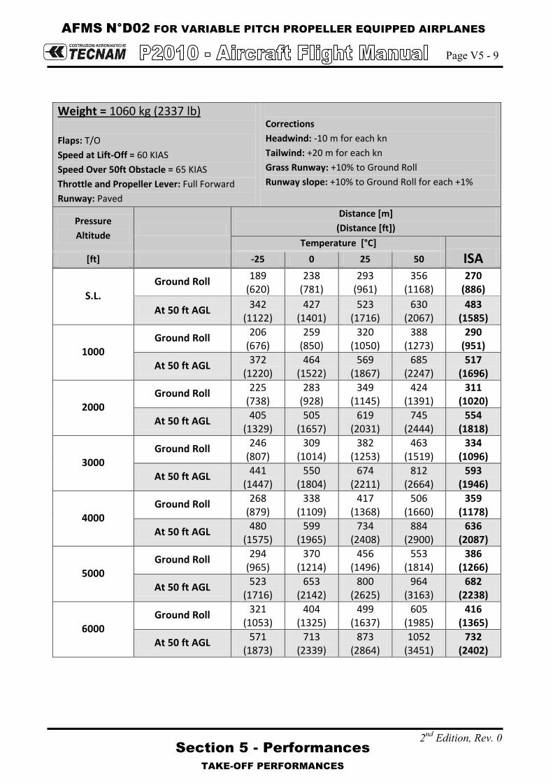
AFMS N°D02 FOR VARIABLE PITCH PROPELLER EQUIPPED AIRPLANES
Page V5 - 9
Section 5 - Performances
TAKE-OFF PERFORMANCES
2nd Edition, Rev. 0
Weight = 1060 kg (2337 lb)
Flaps: T/O
Speed at Lift-Off = 60 KIAS
Speed Over 50ft Obstacle = 65 KIAS
Throttle and Propeller Lever: Full Forward
Runway: Paved
Corrections
Headwind: -10 m for each kn
Tailwind: +20 m for each kn
Grass Runway: +10% to Ground Roll
Runway slope: +10% to Ground Roll for each +1%
Pressure
Altitude
Distance [m]
(Distance [ft])
Temperature [°C]
ISA [ft] -25 0 25 50
S.L.
Ground Roll 189
(620) 238
(781) 293
(961) 356
(1168) 270
(886)
At 50 ft AGL 342
(1122) 427
(1401) 523
(1716) 630
(2067) 483
(1585)
1000 Ground Roll
206 (676)
259 (850)
320 (1050)
388 (1273)
290 (951)
At 50 ft AGL 372
(1220) 464
(1522) 569
(1867) 685
(2247) 517
(1696)
2000 Ground Roll
225 (738)
283 (928)
349 (1145)
424 (1391)
311 (1020)
At 50 ft AGL 405
(1329) 505
(1657) 619
(2031) 745
(2444) 554
(1818)
3000 Ground Roll
246 (807)
309 (1014)
382 (1253)
463 (1519)
334 (1096)
At 50 ft AGL 441
(1447) 550
(1804) 674
(2211) 812
(2664) 593
(1946)
4000 Ground Roll
268 (879)
338 (1109)
417 (1368)
506 (1660)
359 (1178)
At 50 ft AGL 480
(1575) 599
(1965) 734
(2408) 884
(2900) 636
(2087)
5000 Ground Roll
294 (965)
370 (1214)
456 (1496)
553 (1814)
386 (1266)
At 50 ft AGL 523
(1716) 653
(2142) 800
(2625) 964
(3163) 682
(2238)
6000 Ground Roll
321 (1053)
404 (1325)
499 (1637)
605 (1985)
416 (1365)
At 50 ft AGL 571
(1873) 713
(2339) 873
(2864) 1052
(3451) 732
(2402)

AFMS N°D02 FOR VARIABLE PITCH PROPELLER EQUIPPED AIRPLANES
Page V5 - 10
Section 5 - Performances
TAKE-OFF PERFORMANCES
2nd Edition, Rev. 0
Weight = 960 kg (2116 lb)
Flaps: T/O
Speed at Lift-Off = 60 KIAS
Speed Over 50ft Obstacle = 65 KIAS
Throttle and Propeller Lever: Full Forward
Runway: Paved
Corrections
Headwind: -10 m for each kn
Tailwind: +20 m for each kn
Grass Runway: +10% to Ground Roll
Runway slope: +10% to Ground Roll for each +1%
Pressure
Altitude
Distance [m]
(Distance [ft])
Temperature [°C]
ISA [ft] -25 0 25 50
S.L. Ground Roll
149 (489)
187 (614)
231 (758)
281 (922)
213 (699)
At 50 ft AGL 272
(892) 340
(1115) 416
(1365) 501
(1644) 384
(1260)
1000 Ground Roll
162 (531)
204 (669)
252 (827)
306 (1004)
229 (751)
At 50 ft AGL 296
(971) 369
(1211) 452
(1483) 545
(1788) 411
(1348)
2000 Ground Roll
177 (581)
223 732)
275 (902)
334 (1096)
245 (804)
At 50 ft AGL 322
(1056) 402
(1319) 492
(1614) 593
(1946) 440
(1444)
3000 Ground Roll
194 (636)
244 (801)
301 (988)
365 (1198)
264 (866)
At 50 ft AGL 350
(1148) 438
(1437) 536
(1759) 645
(2116) 472
(1549)
4000 Ground Roll
212 (696)
266 (873)
329 (1079)
399 (1309)
283 (928)
At 50 ft AGL 382
(1253) 477
(1565) 584
(1916) 703
(2306) 506
(1660)
5000 Ground Roll
231 (758)
291 (955)
360 (1181)
436 (1430)
305 (1001)
At 50 ft AGL 416
(1365) 520
(1706) 636
(2087) 766
(2513) 542
(1778)
6000 Ground Roll
253 (830)
319 (1047)
393 (1289)
477 (1565)
328 (1076)
At 50 ft AGL 454
(1489) 567
(1860) 694
(2277) 836
(2743) 582
(1909)

AFMS N°D02 FOR VARIABLE PITCH PROPELLER EQUIPPED AIRPLANES
Page V5 - 11
Section 5 - Performances
TAKE-OFF RATE OF CLIMB
2nd Edition, Rev. 0
8. TAKE-OFF RATE OF CLIMB
To account for likely in service performance variations apply a factored to rate of climb of 0.90
Throttle Lever: Full Forward Propeller: 2600 RPM Flaps: Take-Off
Weight Pressure Altitude
Climb Speed
Vy
Rate of Climb [ft/min]
Temperature [°C]
ISA [kg]
([lb]) [ft] [KIAS] -25 0 25 50
1160 (2557)
S.L. 72 974 808 659 525 717
2000 71 848 684 538 406 617
4000 70 721 560 417 287 518
6000 69 596 437 296 169 419
8000 68 470 315 176 51 320
10000 67 345 193 56 -67 221
12000 67 221 71 -63 -184 122
14000 66 96 -51 -182 -300 23
1060 (2337)
S.L. 70 1118 943 787 647 848
2000 69 985 813 660 522 744
4000 69 853 684 533 397 640
6000 68 721 555 406 273 536
8000 68 589 426 280 149 431
10000 67 458 298 155 26 327
12000 66 327 170 29 -97 223
14000 66 197 43 -95 -220 119
960 (2116)
S.L. 69 1288 1103 937 787 1001
2000 69 1147 964 801 654 890
4000 68 1006 827 666 522 780
6000 68 866 689 532 390 669
8000 67 726 553 398 258 558
10000 66 586 416 264 127 448
12000 66 447 280 131 -3 337
14000 65 309 145 -2 -134 226
NOTE

AFMS N°D02 FOR VARIABLE PITCH PROPELLER EQUIPPED AIRPLANES
Page V5 - 12
Section 5 - Performances
EN-ROUTE RATE OF CLIMB
2nd Edition, Rev. 0
9. EN-ROUTE RATE OF CLIMB
To account for likely in service performance variations apply a factored to rate of climb of 0.90
Throttle Lever: Full Forward Propeller: 2600 RPM Flaps: UP
Weight Pressure Altitude
Climb Speed
VY
Rate of Climb [ft/min]
Temperature [°C]
ISA [kg]
([lb]) [ft]
[KIAS] -25 0 25 50
1160 (2557)
S.L. 82 1131 944 776 625 841
2000 81 989 804 639 491 729
4000 80 846 665 503 357 618
6000 79 705 526 367 224 506
8000 78 563 388 232 91 394
10000 77 423 251 97 -41 282
12000 76 282 113 -37 -173 171
14000 76 142 -23 -171 -305 59
1060 (2337)
S.L. 82 1284 1085 907 747 976
2000 81 1133 937 762 605 857
4000 80 982 789 618 463 739
6000 79 831 642 474 322 621
8000 78 682 496 330 181 502
10000 77 532 350 187 40 384
12000 76 383 204 45 -99 265
14000 75 235 59 -97 -239 147
960 (2116)
S.L. 81 1465 1251 1060 888 1134
2000 80 1302 1092 905 735 1007
4000 79 1140 934 749 583 880
6000 78 979 776 595 432 753
8000 77 818 619 441 281 625
10000 76 658 462 287 130 498
12000 75 498 306 134 -20 371
14000 74 339 150 -18 -170 244
NOTE

AFMS N°D02 FOR VARIABLE PITCH PROPELLER EQUIPPED AIRPLANES
Page V5 - 13
Section 5 - Performances
CRUISE PERFORMANCE
2nd Edition, Rev. 0
10. CRUISE PERFORMANCE
Weight: 1160 kg (2557 lb) Pressure Altitude: 0 ft Mixture: FULL RICH
ISA – 30°C (-15°C) ISA (15°C) ISA + 30°C (45°C)
RPM
MAP [inHg]
PWR [%MCP]
TAS [kn]
F.C. [gal/h] ([L/h])
PWR [%MCP]
TAS [kn]
F.C. [gal/h] ([L/h])
PWR [%MCP]
TAS [kn]
F.C. [gal/h] ([L/h])
2700 29.9 113 138 19.2 (72.7) 107 139 18.4 (69.7) 102 141 17.7 (67)
2600
29.9 109 136 18.7 (70.8) 103 138 17.9 (67.8) 98 139 17.2 (65.1)
28 101 132 17.6 (66.6) 96 134 16.9 (64) 91 135 16.3 (61.7)
26 90 126 16.1 (60.9) 85 127 15.4 (58.3) 81 128 14.9 (56.4)
24 79 120 14.7 (55.6) 75 121 14.1 (53.4) 71 121 13.6 (51.5)
22 69 113 13.3 (50.3) 65 113 12.8 (48.5) 62 113 12.4 (46.9)
20 59 105 11.9 (45) 56 104 11.5 (43.5) 53 103 11.1 (42)
2450
29.9 103 133 17.9 (67.8) 98 135 17.1 (64.7) 93 136 16.5 (62.5)
28 95 129 16.8 (63.6) 90 130 16.1 (60.9) 85 131 15.5 (58.7)
26 85 123 15.4 (58.3) 80 124 14.8 (56) 76 125 14.3 (54.1)
24 75 117 14.1 (53.4) 71 117 13.5 (51.1) 67 118 13.1 (49.6)
22 65 110 12.8 (48.5) 62 110 12.3 (46.6) 59 110 11.9 (45)
20 55 102 11.5 (43.5) 52 101 11.1 (42) 50 100 10.7 (40.5)
2350
29.9 100 131 17.4 (65.9) 94 133 16.7 (63.2) 90 134 16.1 (60.9)
28 91 127 16.2 (61.3) 86 128 15.6 (59.1) 82 129 15 (56.8)
26 81 121 15 (56.8) 77 122 14.4 (54.5) 73 123 13.9 (52.6)
24 72 115 13.7 (51.9) 68 115 13.1 (49.6) 65 115 12.7 (48.1)
22 62 108 12.4 (46.9) 59 108 12 (45.4) 56 107 11.6 (43.9)
20 53 99 11.1 (42) 50 98 10.7 (40.5) 48 96 10.4 (39.4)

AFMS N°D02 FOR VARIABLE PITCH PROPELLER EQUIPPED AIRPLANES
Page V5 - 14
Section 5 - Performances
CRUISE PERFORMANCE
2nd Edition, Rev. 0
Weight: 1160 kg (2557 lb) Pressure Altitude: 3000 ft Mixture: FULL RICH
ISA – 30°C (-21°C) ISA (9°C) ISA + 30°C (39°C)
RPM
MAP [inHg]
PWR [%MCP]
TAS [kn]
F.C. [gal/h] ([L/h])
PWR [%MCP]
TAS [kn]
F.C. [gal/h] ([L/h])
PWR [%MCP]
TAS [kn]
F.C. [gal/h] ([L/h])
2700 26.8 104 137 17.9 (67.8) 98 138 17.2 (65.1) 93 139 16.5 (62.5)
2600
26.8 100 135 17.4 (65.9) 94 136 16.7 (63.2) 90 137 16.1 (60.9)
26 96 133 16.9 (64) 90 134 16.2 (61.3) 86 135 15.6 (59.1)
24 85 126 15.4 (58.3) 80 127 14.8 (56) 76 128 14.3 (54.1)
22 76 128 14.3 (54.1) 70 120 13.5 (51.1) 67 120 13 (49.2)
20 63 111 12.6 (47.7) 60 111 12.1 (45.8) 57 110 11.7 (44.3)
18 53 101 11.1 (42) 50 99 10.7 (40.5) 47 97 10.4 (39.4)
2450
26.8 94 132 16.6 (62.8) 89 132 15.9 (60.2) 84 133 15.3 (57.9)
26 90 129 16.1 (60.9) 85 129 15.4 (58.3) 81 130 14.8 (56)
24 80 123 14.7 (55.6) 75 123 14.2 (53.8) 72 124 13.7 (51.9)
22 70 116 13.5 (51.1) 66 116 12.9 (48.8) 63 117 12.5 (47.3)
20 60 108 12.1 (45.8) 57 108 11.6 (43.9) 54 107 11.3 (42.8)
18 50 97 10.7 (40.5) 47 97 10.4 (39.4) 45 95 10.1 (38.2)
2350
26.8 90 130 16.1 (60.9) 85 131 15.5 (58.7) 81 131 14.9 (56.4)
26 86 127 15.6 (59.1) 81 128 15 (56.8) 77 129 14.4 (54.5)
24 77 121 14.3 (54.1) 72 122 13.8 (52.2) 69 122 13.3 (50.3)
22 67 114 13.1 (49.6) 64 114 12.6 (47.7) 60 114 12.2 (46.2)
20 57 105 11.7 (44.3) 54 105 11.3 (42.8) 51 103 11 (41.6)
18.5 50 98 10.7 (40.5) 47 95 10.4 (39.4) 45 92 10.1 (38.2)

AFMS N°D02 FOR VARIABLE PITCH PROPELLER EQUIPPED AIRPLANES
Page V5 - 15
Section 5 - Performances
CRUISE PERFORMANCE
2nd Edition, Rev. 0
Weight: 1160 kg (2557 lb) Pressure Altitude: 6000 ft Mixture: FULL RICH
ISA – 30°C (-27°C) ISA (3°C) ISA + 30°C (33°C)
RPM
MAP [inHg]
PWR [%MCP]
TAS [kn]
F.C. [gal/h] ([L/h])
PWR [%MCP]
TAS [kn]
F.C. [gal/h] ([L/h])
PWR [%MCP]
TAS [kn]
F.C. [gal/h] ([L/h])
2700 23.9 94 135 16.6 (62.8) 89 136 15.9 (60.2) 84 137 15.3 (57.9)
2600
23.9 90 133 16.1 (60.9) 85 134 15.5 (58.7) 81 134 14.9 (56.4)
23 85 130 15.5 (58.7) 80 130 14.8 (56) 76 131 14.3 (54.1)
22 80 126 14.8 (56) 75 127 14.2 (53.8) 72 127 13.6 (51.5)
20 68 117 13.2 (50) 64 117 12.7 (48.1) 61 117 12.3 (46.6)
19 63 113 12.5 (47.3) 59 112 12 (45.4) 56 111 11.6 (43.9)
18 57 108 11.7 (44.3) 54 106 11.3 (42.8) 51 104 10.9 (41.3)
2450
23.9 85 129 15.4 (58.3) 80 130 14.8 (56) 76 131 14.2 (53.8)
23 80 126 14.8 (56) 75 127 14.2 (53.8) 72 127 13.7 (51.9)
22 75 123 14.1 (53.4) 71 123 13.6 (51.5) 67 123 13.1 (49.6)
20 64 114 12.7 (48.1) 61 114 12.2 (46.2) 58 113 11.8 (44.7)
19 59 110 12 (45.4) 56 109 11.6 (43.9) 53 107 11.2 (42.4)
18 54 104 11.3 (42.8) 51 102 10.9 (41.3) 49 99 10.6 (40.1)
2350
23.9 81 127 15 (56.8) 77 128 14.4 (54.5) 73 128 13.8 (52.2)
23 77 124 14.3 (54.1) 73 124 13.8 (52.2) 69 124 13.3 (50.3)
22 72 121 13.7 (51.9) 68 121 13.2 (50) 65 120 12.7 (48.1)
20 62 112 12.3 (46.6) 58 111 11.9 (45) 55 110 11.5 (43.5)
19 57 107 11.7 (44.3) 54 106 11.2 (42.4) 51 103 10.9 (41.3)
18.5 54 104 11.3 (42.8) 51 102 10.9 (41.3) 49 99 10.6 (40.1)

AFMS N°D02 FOR VARIABLE PITCH PROPELLER EQUIPPED AIRPLANES
Page V5 - 16
Section 5 - Performances
CRUISE PERFORMANCE
2nd Edition, Rev. 0
Weight: 1160 kg (2557 lb) Pressure Altitude: 9000 ft Mixture: FULL RICH
ISA – 30°C (-33°C) ISA (-3°C) ISA + 30°C (27°C)
RPM
MAP [inHg]
PWR [%MCP]
TAS [kn]
F.C. [gal/h] ([L/h])
PWR [%MCP]
TAS [kn]
F.C. [gal/h] ([L/h])
PWR [%MCP]
TAS [kn]
F.C. [gal/h] ([L/h])
2700 21.3 85 133 15.4 (58.3) 80 133 14.7 (55.6) 76 133 14.2 (53.8)
2600
21.3 81 130 15 (56.8) 77 131 14.3 (54.1) 73 131 13.8 (52.2)
20 73 124 13.8 (52.2) 69 124 13.3 (50.3) 65 123 12.8 (48.5)
19 67 119 13.1 (49.6) 64 119 12.6 (47.7) 60 118 12.1 (45.8)
18 62 114 12.3 (46.6) 58 113 11.9 (45) 55 111 11.5 (43.5)
2450
21.3 77 127 14.3 (54.1) 72 127 13.7 (51.9) 69 127 13.2 (50)
20 69 121 13.3 (50.3) 65 121 12.8 (48.5) 62 119 12.3 (46.6)
19 64 116 12.6 (47.7) 60 115 12.1 (45.8) 57 114 11.7 (44.3)
18 59 111 11.9 (45) 55 109 11.4 (43.2) 52 106 11.1 (42)
2350 19 66 121 12.9 (48.8) 62 120 12.4 (46.9) 59 117 11.9 (45)
18 60 115 12.2 (46.2) 57 113 11.7 (44.3) 54 110 11.3 (42.8)
Weight: 1160 kg (2557 lb) Pressure Altitude: 12000 ft Mixture: FULL RICH
ISA – 30°C (-39°C) ISA (-9°C) ISA + 30°C (21°C)
RPM
MAP [inHg]
PWR [%MCP]
TAS [kn]
F.C. [gal/h] ([L/h])
PWR [%MCP]
TAS [kn]
F.C. [gal/h] ([L/h])
PWR [%MCP]
TAS [kn]
F.C. [gal/h] ([L/h])
2700 19 75 128 14.1 (53.4) 70 128 13.5 (51.1) 67 128 13 (49.2)
2600 19 72 126 13.7 (51.9) 68 126 13.2 (50) 64 125 12.7 (48.1)
18 66 121 13 (49.2) 63 120 12.4 (46.9) 59 118 12 (45.4)
2450 19 68 123 13.2 (50) 64 122 12.7 (48.1) 61 121 12.2 (46.2)
18 63 118 12.5 (47.3) 59 116 12 (45.4) 56 113 11.6 (43.9)
2350 19 66 121 12.9 (48.8) 62 120 12.4 (46.9) 59 117 11.9 (45)
18 60 115 12.2 (46.2) 57 113 11.7 (44.3) 54 110 11.3 (42.8)

AFMS N°D02 FOR VARIABLE PITCH PROPELLER EQUIPPED AIRPLANES
Section 5 - Performances
LANDING PERFORMANCES
2nd Edition, Rev. 0
Page V5 - 17
11. LANDING PERFORMANCES
To account for likely in service performance variations apply a factored to distances of 1.67
Weight = 1160 kg (2557 lb) Flaps: LAND Short Final Approach Speed = 66 KIAS
Throttle Lever: Idle Runway: Paved
Corrections
Headwind: -4 m for each kn
Tailwind: +13 m for each kn
Grass Runway: +10% to Ground Roll Runway slope: -3% to Ground Roll for each +1%
Pressure Altitude
Distance [m]
(Distance [ft])
Temperature [°C] ISA
[ft] -25 0 25 50
S.L. Ground Roll
204 (669)
225 (738)
245 (804)
266 (873)
237 (778)
At 50 ft AGL 488
(1601) 509
(1670) 529
(1736) 550
(1804) 521
(1709)
1000 Ground Roll
212 (696)
233 (764)
254 (833)
276 (906)
244 (801)
At 50 ft AGL 496
(1627) 517
(1696) 538
(1765) 560
(1837) 528
(1732)
2000 Ground Roll
220 (722)
242 (794)
264 (866)
286 (938)
251 (823)
At 50 ft AGL 504
(1654) 526
(1726) 548
(1798) 570
(1870) 535
(1755)
3000 Ground Roll
228 (748)
251 (823)
274 (899)
297 (974)
259 (850)
At 50 ft AGL 512
(1680) 535
(1755) 558
(1831) 581
(1906) 543
(1781)
4000 Ground Roll
236 (774)
260 (853)
284 (932)
308 (1010)
267 (876)
At 50 ft AGL 520
(1706) 544
(1785) 568
(1864) 592
(1942) 551
(1808)
5000 Ground Roll
245 (804)
270 (886)
295 (968)
320 (1050)
275 (902)
At 50 ft AGL 529
(1736) 554
(1818) 579
(1900) 604
(1982) 559
(1834)
6000 Ground Roll
255 (837)
280 (919)
306 (1004)
332 (1089)
284 (932)
At 50 ft AGL 539
(1768) 564
(1850) 590
(1936) 616
(2021) 568
(1864)
NOTE

AFMS N°D02 FOR VARIABLE PITCH PROPELLER EQUIPPED AIRPLANES
Page V5 - 18
Section 5 - Performances
BALKED LANDING PERFORMANCE
2nd Edition, Rev. 0
12. BALKED LANDING PERFORMANCE
To account for likely in service performance variations apply a factored to rate of climb and to angle of climb of 0.90
Throttle and Propeller Lever: Full Forward Flaps: LAND Speed: 67 KIAS
Weight Pressure Altitude
Steady Gradient of Climb [%]
Temperature [°C]
ISA [kg]
([lb]) [ft] -25 0 25 50
1160 (2557)
S.L. 10.9 8.6 6.6 4.7 7.4
1000 10.0 7.8 5.7 3.9 6.7
2000 9.2 6.9 4.9 3.1 6.0
3000 8.3 6.1 4.1 2.3 5.3
4000 7.4 5.2 3.2 1.4 4.6
5000 6.6 4.4 2.4 0.6 3.9
6000 5.7 3.5 1.6 -0.2 3.3
7000 4.8 2.7 0.7 -1.0 2.6
1060 (2337)
S.L. 12.9 10.4 8.1 6.1 9.0
1000 11.9 9.4 7.2 5.2 8.3
2000 11.0 8.5 6.3 4.3 7.5
3000 10.0 7.6 5.4 3.4 6.8
4000 9.1 6.7 4.5 2.5 6.0
5000 8.1 5.7 3.6 1.7 5.3
6000 7.2 4.8 2.7 0.8 4.5
7000 6.2 3.9 1.8 -0.1 3.8
960 (2116)
S.L. 15.2 12.4 10 7.7 10.9
1000 14.1 11.4 9.0 6.7 10.1
2000 13.1 10.4 7.9 5.8 9.3
3000 12.0 9.3 6.9 4.8 8.4
4000 11.0 8.3 5.9 3.8 7.6
5000 10.0 7.3 4.9 2.8 6.8
6000 8.9 6.3 3.9 1.8 6.0
7000 7.9 5.3 2.9 0.9 5.2
NOTE

AFMS N°D02 FOR VARIABLE PITCH PROPELLER EQUIPPED AIRPLANES
Page V5 - 19
Section 5 - Performances
NOISE DATA
2nd Edition, Rev. 0
13. NOISE DATA
Noise level, determined in accordance with ICAO/Annex 16 6th Ed., July 2011, Vol. I°, Chapter 10 and 14 CFR 36.1581(c), is 80.58 dB(A).
NOTE: No determination has been made by the Federal Aviation Administration that the noise levels of this aircraft are or should be acceptable or unacceptable for operation at, into, or out of, any airport.

AFMS N°D02 FOR VARIABLE PITCH PROPELLER EQUIPPED AIRPLANES
Page V5 - 20
Section 5 - Performances
2nd Edition, Rev. 0
INTENTIONALLY LEFT BLANK

AFMS N°D02 FOR VARIABLE PITCH PROPELLER EQUIPPED AIRPLANES
Page D02-16
Section 9 – Supplements
Supplement no. D02 – Variable pitch propeller
GENERAL FEATURES
2nd Edition, Rev. 0
SECTION 7 – AIRCRAFT AND SYSTEMS DESCRIPTION
Make sure you first applied instructions reported on the basic AFM, Section 7 Aircraft and Systems Description
Apply following pages replacement:
Supplement D02 – Performances page
AFM Section 7 page
V7-10 thru 11 REPLACES Page 7-10 thru 11 of AFM, Section 7
V7-16 REPLACES Page 7-16 of AFM, Section 7
V7-27 REPLACES Page 7-27 of AFM, Section 7
V7-36 REPLACES Page 7-36 of AFM, Section 7
Supplement D02: pages replacement instructions

AFMS N°D02 FOR VARIABLE PITCH PROPELLER EQUIPPED AIRPLANES
Page D02-17
Section 9 – Supplements
Supplement no. D02 – Variable pitch propeller
2nd Edition, Rev. 0
INTENTIONALLY LEFT BLANK

AFMS N°D02 FOR VARIABLE PITCH PROPELLER EQUIPPED AIRPLANES
Page V7-10
Section 9 – Supplements
ENGINE CONTROLS
2nd Edition, Rev. 0
4.1 ENGINE CONTROL LEVER
Engine handling is via three levers: Throttle, RPM lever, Mixture control lever. They’re situated on the center control; the use of “front/forward” and “rear/backward” is defined in relation to the direction of flight (longitudinal). Mixture control lever This lever (right hand lever with red handle) controls the fuel-air mixture, which is supplied to the engine. With the lever full forward, extra fuel is being supplied to the engine which at higher performance setting contributes to engine cooling. In cruise, the mixture should be made leaner in order to reach the appropriate fuel-air mixture. The leaning procedure is given in Chapter 4.
Lever forward (RICH) >> Mixture rich (in fuel) Lever to rear (LEAN) >>Mixture lean (in fuel)
To shut off the engine the mixture control lever is pulled to the rear stop: air without fuel is drawn into the cylinders that shuts down. Throttle This lever (left hand with large knob) is used to control manifold pressure (MAP). High manifold pressure means a large quantity of fuel-air mixture is being supplied to engine, while low manifold pressure means a lesser quantity of fuel-air mixture is being supplied. Propeller lever By means of this lever (central lever with blue handle) the propeller governor controls the propeller pitch, and consequently engine RPM. A selected RPM is held constant by the governor independent of the airspeed and the throttle setting.
Lever forward (HIGH RPM) = fine pitch Lever rearward (LOW RPM) = coarse pitch
Following a defect in governor or oil system, the blades go to the finest possible pitch (maximum RPM), thus allowing continuation of the flight.
CAUTION
Following failure of the governor or a serious drop in oil pressure, the RPM should be adjusted using the throttle. Every effort should be made not to exceed 2700 RPM.
CAUTION
The throttle and RPM lever should be moved slowly, in order to avoid over-speed and excessively rapid RPM changes.

AFMS N°D02 FOR VARIABLE PITCH PROPELLER EQUIPPED AIRPLANES
Page V7-11
Section 9 – Supplements
ENGINE CONTROLS
2nd Edition, Rev. 0
4.2 ALTERNATE AIR
Alternate Air knob is located on the central pedestal; when the knob is fully pulled outward from the instrument panel, injectors receive maximum hot air. During nor-mal operation, the knob is set in OFF position.
4.3 DEFROST AND CABIN HEAT
Two knobs, located on the lower side of the central pedestal, allow Defrost and Cabin Heat function. The one marked as “Defrost and Cabin Heat” allows hot air to perform windshield defrost and partially cabin heat. The cabin heat control knob, when fully outward, allows cabin to receive maximum hot air. When both cabin heat and defrost and cabin heat are pulled, air is partitioned.
Fig. 7-9. CENTRAL PEDESTAL

AFMS N°D02 FOR VARIABLE PITCH PROPELLER EQUIPPED AIRPLANES
Page V7-16
Section 9 – Supplements
POWERPLANT
2nd Edition, Rev. 0
7. POWERPLANT
7.1. ENGINE
Manufacturer …………………………… Lycoming Textron Model …………………………………... IO-360-M1A Type Certificate ………………………... EASA TCDS no. IM.E.032 Engine type …………………………….. Fuel injected (IO), direct drive, four cylinder
horizontally opposed, air cooled with down exhaust outlets.
Maximum power ……. Maximum continuous power …………...
134.0 kW (180hp) @ 2700 rpm 129.2 kW (173.3hp) @ 2600 rpm
Oil Consumption Operation RPM HP Max.
Oil Cons. Qts./Hr.
*Max. Cyl. Head
Temp. Normal Rated 2700 180 .80 500°F (260°C) Performance Cruise (75%) 2450 135 .45 500°F (260°C) Economy Cruise (60R Rated) 2350 117 .39 500°F (260°C)
7.2. PROPELLER
Manufacturer ………………………….. MT Propeller Model …………………………………. MTV-15-B/193-52 Type Certificate ……………………….. EASA TCDS no. P.098 Blades/hub …………………………….. wood/composite 2-blades – aluminium hub Diameter ………………………………. 1930 mm (6,33 ft) no reduction allowed Type …………………………………… Variable pitch
Governor Manufacturer ………………………….. MT Propeller Model …………………………………. P-860-23: Type Hydraulic

AFMS N°D02 FOR VARIABLE PITCH PROPELLER EQUIPPED AIRPLANES
Page V7-27
Section 9 – Supplements
LIGHTS
2nd Edition, Rev. 0
7.1. INTERNAL LIGHTS
On the cabin ceiling are located four map lights, two in the front area (pilot) and two in the rear area (passengers). In the central area of the cabin ceiling is located a spot light used to illuminate the pedestal during night flight operations. All ceiling lights are dimmable by a dedicat-ed dimmer.
FIG.7-18. CABIN CEILING LIGHTS LAYOUT
The instrument panel can be illuminated by 8 incandescence light strips, all dimma-ble.
FIG.7-19. INSTRUMENT PANEL LIGHTS LAYOUT
FWD
From mid MAP light (ceiling)

AFMS N°D02 FOR VARIABLE PITCH PROPELLER EQUIPPED AIRPLANES
Page V7-36
Section 9 – Supplements
PLACARDS
2nd Edition, Rev. 0
Pedestal placards:

Page D03-1
Section 9 - Supplements -
Supplement no. D03 - ALTERNATIVE AVIONICS CONFIGURATION
Ed. 1, Rev. 0
Supplement no. D03-
AFMS FOR ALTERNATIVE AVIONICS CONFIGURATION
Record of Revisions
Rev Revised page
Description of Revision
Tecnam Approval EASA Approval or Under DOA
Privileges DO OoA HDO
0 - First Issue D. Ronca M. Oliva M. Oliva
List of Effective Pages
Page Revision Cover Pages D03-1 thru 22 Rev. 0
Section 2 2G-10, 2G-13 Rev. 0
Section 3 3G-5 thru 7, 3G-10, 3G-16 thru 17, 3G-25 Rev. 0
Section 4 4G-4 thru 5, 4G-9, 4G-15 thru 18, 4G-20, 4G-24 Rev. 0
Section 6 6G-11 thru 12 Rev. 0
Section 7 7G-8 thru 9, 7G-20 thru 24, 7G-27 Rev. 0

Page D03-2
Section 9 - Supplements -
Supplement no. D03 - ALTERNATIVE AVIONICS CONFIGURATION
Ed. 1, Rev. 0
INDEX
INTRODUCTION ..................................................................................... 3
Section 1 – GENERAL ............................................................................ 5
Section 2 – LIMITATIONS ...................................................................... 7
Section 3 – EMERGENCY PROCEDURES ............................................. 10
Section 4 – NORMAL PROCEDURES ................................................... 13
Section 5 – PERFORMANCE ................................................................ 16
Section 6 – WEIGHT AND BALANCE ................................................... 18
Section 7 – AIRFRAME AND SYSTEMS DESCRIPTION ....................... 20
Section 8 – GROUND HANDLING & SERVICE ..................................... 22

Page D03-3
Section 9 - Supplements -
Supplement no. D03 - ALTERNATIVE AVIONICS CONFIGURATION
Ed. 1, Rev. 0
INTRODUCTION
The information contained herein supplements or supersedes the basic Aircraft Flight Manual: detailed instructions are provided to allow the owner for replacing the AFM pages containing information amended as per Garmin G500 in subject. It is the owner’s responsibility to replace the mentioned pages in accordance with the instructions herein addressed section by section.

Page D03-4
Section 9 - Supplements -
Supplement no. D03 - ALTERNATIVE AVIONICS CONFIGURATION
Ed. 1, Rev. 0
INTENTIONALLY LEFT BLANK
Page D03-5
Section 9 - Supplements -
Supplement no. D03 - ALTERNATIVE AVIONICS CONFIGURATION
Ed. 1, Rev. 0
SECTION 1 – GENERAL
Make sure you first applied instructions reported on the basic AFM, Section 1 General
According to A/C configuration refer to the basic AFM, Section 1 – General
Supplement D03: pages replacement instructions

Page D03-6
Section 9 - Supplements -
Supplement no. D03 - ALTERNATIVE AVIONICS CONFIGURATION
Ed. 1, Rev. 0
INTENTIONALLY LEFT BLANK

Page D03-7
Section 9 - Supplements -
Supplement no. D03 - ALTERNATIVE AVIONICS CONFIGURATION
Ed. 1, Rev. 0
SECTION 2 – LIMITATIONS
Make sure you first applied instructions reported on the basic AFM, Section 2 Limitations
According A/C configuration apply following pages replacement:
Supplement D03 LIMITATIONS
page AFM
Section 2 page
2G-13 REPLACES Page 2-13 of basic AFM, Section 2
Supplement D03: pages replacement instructions

Page D03-8
Section 9 - Supplements -
Supplement no. D03 - ALTERNATIVE AVIONICS CONFIGURATION
Ed. 1, Rev. 0
INTENTIONALLY LEFT BLANK

AFMS N°D03 FOR ALTERNATIVE AVIONICS CONFIGURATION
Page 2G-13
Section 2 – Limitations
KOEL
Ed. 1, Rev. 0
18. KINDS OF OPERATION EQUIPMENT LIST (KOEL)
This paragraph reports the KOEL table, concerning the equipment list required on board under CS-23 regulations to allow flight operations in VFR Day/Night and IFR Day/Night. Flight in VFR Day/Night and IFR is permitted only if the prescribed equipment is in-stalled and operational. Additional equipment, or a different equipment list, for the in-tended operation may be required by national operational requirements and also depends on the airspace classification and route to be flown. The owner is responsible for fulfilling these requirements.
Equipment VFR Day VFR Night IFR Day IFR Night Note
External Power Circuit Breakers ● ● ● ● As Required Battery ● ● ● ● Safety Equipment & Furnishing First Aid kit ● ● ● ● Fire extinguisher ● ● ● ● ELT ● ● ● ● Torch (with spare batt.) ● ● Ice Protection Pitot heating system ● ● ● Landing Gear Wheel pants Removable Lights Landing/taxi lights ● ● ● ● Strobe lights ● ● ● ● NAV lights ● ● ● ● Cabin lights ● ● Instrument lights ● ● Emergency light ● ● Dimming Devices ● ● Day/Night switch ● ● COM/Navigation/Engine parameters Magnetic compass ● ● ● ● GARMIN G500 Suite ● ● ● ● GDU 620 (PFD/MFD) ● ● ● ● MD 302 suite ● ● ● ● GTN 650 ● ● ● ● GNC 255A ● ● ● ● GMA 340 ● ● ● ● DME Indicator-KDI 572 ● ● ● ● ADF system - KR 87 ● ● ● ● JP Instruments EDM 930 ● ● ● ● Remote Alarm Display ● ● ● ● Pitot system ● ● ● ● Clock ● ● ● ● Flight Controls Pitch trim indicator ● ● ● ● Flap System ● ● ● ● Flaps position lights ● ● ● ● Rudder trim indicator ● ● ● ● Rudder trim system ● ● ● ● only for VFR operations, rudder
trim system may be inoperative provided the trim tab is fixed in the streamlined position and the system is electrically disabled
Stall warning system ● ● ● ● VFR Day VFR Night IFR Day IFR Night

Page D03-09
Section 9 - Supplements -
Supplement no. D03 - ALTERNATIVE AVIONICS CONFIGURATION
Ed. 1, Rev. 0
INTENTIONALLY LEFT BLANK

Page D03-10
Section 9 - Supplements -
Supplement no. D03 - ALTERNATIVE AVIONICS CONFIGURATION
Ed 1, Rev. 0
SECTION 3 – EMERGENCY PROCEDURES
Make sure you first applied instructions reported on the basic AFM, Section 3 Emergency Procedures
According A/C configuration apply following pages replacement:
Supplement D03
EMERGENCY PROCEDURES page
AFM Section 3 page
3G-5 REPLACES 3-5 of basic AFM, Section 3
3G-6 REPLACES 3-6 of basic AFM, Section 3
3G-7 REPLACES 3-7 of basic AFM, Section 3
3G-10 REPLACES 3-10 of basic AFM, Section 3
3G-16 REPLACES 3-16 of basic AFM, Section 3
3G-17 REPLACES 3-17 of basic AFM, Section 3
3G-25 REPLACES 3-25 of basic AFM, Section 3
Supplement D03: pages replacement instructions

Page D03-11
Section 9 - Supplements -
Supplement no. D03 - ALTERNATIVE AVIONICS CONFIGURATION
Ed 1, Rev. 0
INTENTIONALLY LEFT BLANK

AFMS N°D03 FOR ALTERNATIVE AVIONICS CONFIGURATION
Page 3G-5
Section 3 – Emergency procedures
AVIONIC SUITE FAILURES
Ed. 1, Rev.0
2. FAILURES INDICATED ON THE ANNUNCIATION PANEL
The annunciator panel, located on the centre of the instrument panel, contains 9 lights for warnings, cautions and advisories. The colours are as follows: GREEN: to indicate that pertinent device is turned ON AMBER: to indicate no-hazard situations which have to be considered and
which require a proper crew action RED: to indicate emergency conditions WHITE: to indicate advisory messages
2.1 ALTERNATOR FAILURE
If ALT FAIL caution is ON:
1. Circuit breaker(s)……………………... Check
2. Generator SWITCH………………...… OFF
3. Generator SWITCH…………………... ON
If ALT FAIL CAUTION REMAINS on: 4. Generator SWITCH………………...… OFF
A fully charged battery shall supply electrical power for at least 30 minutes.
NOTE

AFMS N°D03 FOR ALTERNATIVE AVIONICS CONFIGURATION
Page 3G-6
Section 3 – Emergency procedures
AVIONIC SUITE FAILURES
Ed. 1, Rev.0
2.2 PITOT HEATING SYSTEM FAILURE
When the Pitot Heating system is activated, the green PITOT HEAT ON ad-visory light turns on and the amber PITOT HEAT caution light turns OFF, indicating that the Pitot Heating system is functioning properly.
If the amber PITOT HEAT caution light is ON when the green PITOT HEAT ON light is on, then the Pitot Heating system is not functioning proper-ly.
In this case apply following procedure: 1. Pitot heat switch ………………………………… OFF 2. Pitot heat circuit breaker …….……………… CHECK IN 3. Pitot heat switch ………………………………… ON 4. PITOT HEAT caution light ………………….. CHECK
if the amber light stays ON, avoid visible moisture and OATs below 10° C. NOTE

AFMS N°D03 FOR ALTERNATIVE AVIONICS CONFIGURATION
Page 3G-7
Section 3 – Emergency procedures
AVIONIC SUITE FAILURES
Ed. 1, Rev.0
3. G500 SYSTEM FAILURES
3.1 LOSS OF INFORMATION DISPLAYED
When a LRU or a LRU function fails, a large red „X‟ is typically displayed on the display field associated with the failed data.
In most of cases, the red “X” annunciation is accompanied by a message advisory alert issuing a flashing ADVISORY Softkey annunciation which, once selected, acknowledges the presence of the message advisory alert and displays the alert text message in the Alerts Window.
3.2 LOSS OF AIRSPEED INFORMATION
AIRSPEED FAIL (RED X ON DISPLAY FIELD)
Display system is not receiving airspeed input from Air Data Computer.
INSTRUCTION: revert to standby instrument
NOTE

AFMS N°D03 FOR ALTERNATIVE AVIONICS CONFIGURATION
Page 3G-10
Section 3 – Emergency procedures
AVIONIC SUITE FAILURES AND LOW FUEL QUANTITY
Ed. 1, Rev.0
3.7 DISPLAY FAILURE
In case of display failure refer to backup instrument (MD302) for primary flight information, and to GTN650 for navigation information.
3.8 LOW FUEL QUANTITY LEFT
If fuel quantity LH is under 24 litres 1. Fuel tank selector …………… Switch to RH fuel tank
3.9 LOW FUEL QUANTITY RIGHT
If fuel quantity RH is under 24 litres 1. Fuel tank selector …………… Switch to LH fuel tank
3.10 LOW FUEL QUANTITY LEFT AND RIGHT
If fuel quantity LH and RH is under 24 litres 1. Land as soon as practical: land at the nearest approved landing area
where suitable repairs can be made.
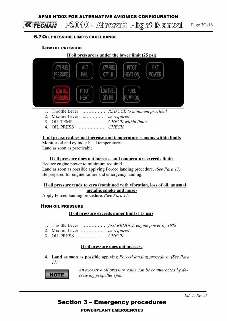
AFMS N°D03 FOR ALTERNATIVE AVIONICS CONFIGURATION
Page 3G-16
Section 3 – Emergency procedures
POWERPLANT EMERGENCIES
Ed. 1, Rev.0
6.7 OIL PRESSURE LIMITS EXCEEDANCE
LOW OIL PRESSURE
If oil pressure is under the lower limit (25 psi)
1. Throttle Lever …………… REDUCE to minimum practical 2. Mixture Lever ...………….. as required 3. OIL TEMP ………………… CHECK within limits 4. OIL PRESS ……………… CHECK
If oil pressure does not increase and temperature remains within limits Monitor oil and cylinder head temperatures. Land as soon as practicable.
If oil pressure does not increase and temperature exceeds limits
Reduce engine power to minimum required. Land as soon as possible applying Forced landing procedure. (See Para 11) Be prepared for engine failure and emergency landing.
If oil pressure tends to zero (combined with vibration, loss of oil, unusual
metallic smoke and noise) Apply Forced landing procedure. (See Para 11)
HIGH OIL PRESSURE
If oil pressure exceeds upper limit (115 psi)
1. Throttle Lever …………… first REDUCE engine power by 10% 2. Mixture Lever ……………... as required 3. OIL PRESS ………………... CHECK
If oil pressure does not increase
4. Land as soon as possible applying Forced landing procedure. (See Para
11) An excessive oil pressure value can be counteracted by de-
creasing propeller rpm. NOTE

AFMS N°D03 FOR ALTERNATIVE AVIONICS CONFIGURATION
Page 3G-17
Section 3 – Emergency procedures
POWERPLANT EMERGENCIES
Ed. 1, Rev.0
6.8 LOW FUEL PRESSURE
If fuel pressure decreases below the lower limit (14 psi)
1. Electric fuel pump………... ON 2. Fuel selector valve………..Select opposite fuel tank if NOT empty 3. Fuel quantity ……………..CHECK
If fuel pressure doesn‟t build up:
1. Land as soon as practical. Prepare for potential engine failure and prepare to apply Forced landing procedure. (See Para 11)
6.9 HIGH FUEL PRESSURE
If fuel pressure increases above the upper limit (35 psi)
1. Land as soon as possible. Prepare for potential engine shut down and
apply Forced landing procedure. (See Para 11)
Possible injector failure or obstruction.

AFMS N°D03 FOR ALTERNATIVE AVIONICS CONFIGURATION
Page 3G-25
1st Edition, Rev.1 Section 3 – Emergency procedures
OTHER EMERGENCIES
10. OTHER EMERGENCIES
10.1 LOSS OF ESSENTIAL BUS
In case of loss of essential bus, the following will be lost (related breakers are listed):
PFD/MFD FLAP ACTUATOR
COM1 PITOT HEAT
GPS/NAV1 STROBE LIGHT
EIS LANDING LIGHT
FUEL PUMP AHRS
FIELD ADC
STALL WARNING ANN. PANEL
XPDR
Electrical power from Alternator is lost, battery will automatically provide energy (duration at least 30 min.). Pilot will need to make reference to standby instrument for primary flight infor-mation and parameters. Pilot will be able to use the audio panel and COM2/NAV2. Engine parameters and related warnings/cautions are lost. Flaps extension and retraction will be lost, apply Flaps control failure procedure (See Para 10.6). Strobe and landing lights will be lost, NAV and taxi lights are still available; taxi light will be the only visual aid for landing in night conditions.
10.2 LOSS OF MAIN BUS
In case of loss of main bus, the main bus voltage will drop to zero. The following will be lost (related breakers are listed):
AUDIO PANEL NAV LIGHT
INSTRUMENT (clock, pitch trim indic.)
A.D.I. (available running on internal bat-tery power)
TAXI LIGHT COM2
INSTR. LIGHT 28/12 VDC CONVERTER NAV2
CABIN LIGHT RUDDER TRIM ACTUATOR ADF
START 12VDC SOCKET DME
Fail safe operation of audio panel allows pilot to transmit and use COM1 using headphones only; speakers will not be available. For night flights, all instrument lights will be lost, but emergency light will still be available.

Page D03-12
Section 9 - Supplements -
Supplement no. D03 - ALTERNATIVE AVIONICS CONFIGURATION
Ed 1, Rev. 0
INTENTIONALLY LEFT BLANK

Page D03-13
Section 9 - Supplements -
Supplement no. D03 - ALTERNATIVE AVIONICS CONFIGURATION
Ed. 1, Rev.0
SECTION 4 – NORMAL PROCEDURES
Make sure you first applied instructions reported on the basic AFM, Section 4 Normal Procedures
According A/C configuration apply following pages replacement:
Supplement D03 –
NORMAL PROCEDURES page
AFM Section 4 page
4G-4 REPLACES Page 4-4 of basic AFM, Section 4
4G-5 REPLACES Page 4-5 of basic AFM, Section 4
4G-9 REPLACES Page 4-9 of basic AFM, Section 4
4G-15 REPLACES Page 4-15 of basic AFM, Section 4
4G-16 REPLACES Page 4-16 of basic AFM, Section 4
4G-17 REPLACES Page 4-17 of basic AFM, Section 4
4G-18 REPLACES Page 4-18 of basic AFM, Section 4
4G-20 REPLACES Page 4-20 of basic AFM, Section 4
4G-24 REPLACES Page 4-24 of basic AFM, Section 4
Supplement D03: pages replacement instructions

Page D03-14
Section 9 - Supplements -
Supplement no. D03 - ALTERNATIVE AVIONICS CONFIGURATION
Ed. 1, Rev.0
INTENTIONALLY LEFT BLANK

AFMS N°D03 FOR ALTERNATIVE AVIONICS CONFIGURATION
Page 4G-4
Section 4 – Normal procedures
IFR FLIGHT: G500 GROUND TRAINING PRE-REQUISITES
Ed. 1, Rev.0
2. IFR FLIGHT: G500 GROUND TRAINING PRE-REQUISITES
The aircraft is equipped with a Garmin G500 avionic suite that integrates radio aids navigation with GPS navigation, providing an outstanding capability to support IFR flight, from basic instrument flight training to complex IFR scenar-io. Depending on national regulations, in some countries flying IFR with a single engine aircraft without autopilot installation and/or single pilot may or may not be allowed, any customer must pay careful attention to check limitations that may apply. The use of G500 software requires full system knowledge (Garmin applicable manual with specific peculiar limitations), careful preparation, ground and pre-flight training before flight. Furthermore, as a minimum during training, it‟s strongly recommended using the avionic suite in IFR with incremental steps after initial basic IFR instruction: 1. Initial use of a single radio-aids (No GPS); 2. Use of two radio-aids (No GPS); 3. Use of GPS for point to point navigation (No approaches); 4. Use of VNAV feature; 5. Full use of avionic suite.
The flight training syllabus for IFR instruction will need to address this incre-mental approach in order to give pilots awareness of full avionic potential, and to highlight the complexity of single pilot usage of G500 Garmin suite enroute or inside high density airspace structure.
CAUTION
During IFR flight, the workload that may develop using full avionic suite could get high in single pilot; pilot planning is important and essential in order to cor-rectly address all avionic functions and aids. Considering the complexity of the G500 suite, sound judgment will be required (weather, airspace complexity, pilot skills) to assess the best option for IFR steer guidance.
NOTE

AFMS N°D03 FOR ALTERNATIVE AVIONICS CONFIGURATION
Page 4G-5
Section 4 – Normal procedures
IFR FLIGHT: G500 GROUND TRAINING PRE-REQUISITES
Ed. 1, Rev.0
The necessity to correct or modify flight plans in the Garmin G500 under these conditions may distract pilots from basic handling causing deviations from as-signed parameters, so careful attention must be exercised to avoid deviations on flying parameters. It’s highly recommended to continue cross-checking flight parameters when en-tering flight data into the G500, especially when trying to create / insert arrival and departure procedures and / or VNAV profiles as the quantity of actions needed is high and may distract pilots from basic and precise handling. The following prescriptions, other than those already present in the G500 manu-al, shall be observed:
- Use of GPS for precision approach navigation mode is not allowed. - Use of GPS is prohibited as primary means for navigation. GPS is approved as sup-
plemental means for navigation; - Use of GPS is prohibited for IFR in terminal area or in non-precision approach op-
erations;
If Receiver Autonomous Integrity Monitoring (RAIM) function becomes una-vailable in enroute phase of flight, position must be verified every 15 minutes using other IFR approved navigation system.
Turbulence and / or Crosswind: Presence of moderate to heavy turbulence and / or strong crosswind conditions (above 20 kts crosswind) will require high drift angle to correct for wind (above 15° drift) and highly reduce spare capabilities to do other concurrent tasks inside the cockpit other than precise flying.
NOTE

AFMS N°D03 FOR ALTERNATIVE AVIONICS CONFIGURATION
Page 4G-9
Section 4 – Normal procedures
PRE-FLIGHT INSPECTION
Ed. 1, Rev. 0
4. PRE-FLIGHT INSPECTION
Before each flight, it is necessary to carry out a complete aircraft check including a cabin inspection followed by an external inspection, as below detailed.
4.1 CABIN INSPECTION
1. Aircraft documents (ARC, Certificate of Airworthiness, Noise certificate, Radio COM certificate, AFM): check current and on board
2. Weight and balance: calculate (ref. to Section 6) and check within limits 3. Breaker: all IN 4. Safety belts: connected to hard points, check condition 5. Ignition key: OFF, key extracted 6. Master switch: ON 7. Voltmeter: check within the limits 8. Lights: all ON, check for operation 9. Annunciator panel: check all lights 10. Acoustic stall warning: check for operation 11. Master switch: OFF 12. Baggage: check first aid kit, ELT, fire extinguisher, luggage secured with
restraint net.

AFMS N°D03 FOR ALTERNATIVE AVIONICS CONFIGURATION
Page 4G-15
Section 4 – Normal procedures
CHECKLISTS
Ed. 1, Rev. 0
5. CHECKLISTS
5.1 BEFORE STARTING ENGINE (AFTER PREFLIGHT INSPECTION)
1. Seat position and safety belts: adjust 2. Flight controls: operate full stroke checking for movement smoothness, free of play and
friction. 3. Parking brake: engage 4. Throttle friction: adjust 5. Throttle: IDLE 6. Mixture control Lever: LEAN 7. Circuit Breakers: check all IN 8. Master switch: ON, wait EDM930 turn on, Check ALT OUT caution ON, Check LOW FP
and LOW OP warning ON 9. Only before the first flight of the day:
Standby Instrument: Check no red crosses displayed. a. Press and hold the control knob (approx. 2 sec) b. Rotate the knob selecting “INFO>” page then press it c. Select “BATTERY INFO” page then press the knob d. Check “CHARGE (%)” to be more than 80%, then exit menu
10. Avionic Master switch: ON 11. Fuel quantity: compare the fuel quantity indicators information with fuel quantity visually checked
into the tanks (see Pre-flight inspection – External inspection), then update the EDM930 fuel con-tent in the totalizer accordingly)
The totalizer function available on EDM930 Engine page allows input only up to 230lts (maximum usable fuel). Initial Fuel indication on totalizer must be corrected manually (as it does not use the aircraft fuel quantity indicators as input). Once correctly initial-ized, fuel consumption on totalizer is very precise as it take instantaneous fuel flow for computation.
12. Electric fuel pump: ON (check for audible pump noise and increase of fuel pressure) 13. Warning “LOW FUEL PRESSURE”: extinguished 14. Electric fuel pump: OFF 15. Flap control: cycle fully extended and then set to T/O 16. Pitch Trim: cycle fully up and down, then set to NEUTRAL 17. Rudder trim: cycle full right and left, then set to NEUTRAL
WARNING
Pitch trim position other than in neutral position would affect take off perfor-mance and take off rotation execution at the correct VR.
18. Nav & Strobe lights: ON
In absence of RH seat occupant: fasten seat belts around the seat in order to pre-vent any interference with the aeroplane flight control operation and with rapid egress in an emergency.
19. Doors: Closed and locked
NOTE
NOTE

AFMS N°D03 FOR ALTERNATIVE AVIONICS CONFIGURATION
Page 4G-16
Section 4 – Normal procedures
CHECKLISTS
Ed. 1, Rev. 0
5.2 ENGINE STARTING
(a) Cold engine 1. Engine throttle: 1cm above idle 2. Fuel selector valve: select the tank with less fuel 3. Electric fuel pump: ON 4. Mixture: full open for 3 – 5” (positive fuel flow indication) then CUT-OFF 5. Propeller area: check that area is clear of persons / objects
WARNING
Check to insure no person or object is present in the area close to the propeller. Forward lower sector visibility is not possible from inside the cockpit.
CAUTION
Do not overheat the starter motor. Do not operate it for more than 10 seconds. After operating the starter motor, let it cool off for 20 seconds. After 6 attempts to start the engine, let the starter cool off for half an hour.
6. Ignition key: BOTH 7. Ignition key: START When engine start turning and first indication of a starting condition exist: 8. Mixture: rapidly move to FULL RICH 9. Throttle: set 1000 – 1200 RPM 10. Check oil pressure rises within 10 sec. 11. Check “OIL PRESSURE LOW”: extinguished 12. Electric fuel pump: OFF 13. Check fuel pressure: within limits 14. Generator switch: ON 15. Voltmeter: increase and check within green arc 16. ALT FAIL caution: extinguished
Avoid idling operations on the ground for optimum engine operation, maintain 1000-1200 RPM, do not exceed 2200 RPM on the ground.
17. Engine instruments: Check within limits 18. Check for annunciator panel with no cautions
NOTE

AFMS N°D03 FOR ALTERNATIVE AVIONICS CONFIGURATION
Page 4G-17
Section 4 – Normal procedures
CHECKLISTS
Ed. 1, Rev. 0
(b) Warm engine 1. Engine throttle: idle 2. Fuel selector valve: select the tank with less fuel 3. Electric fuel pump: ON 4. Propeller area: check for area clear of persons / objects
WARNING
Check to insure no person or object is present in the area close to the propel-ler. Forward lower sector visibility is not possible from inside the cockpit.
CAUTION
Do not overheat the starter motor. Do not operate it for more than 10 se-conds. After operating the starter motor, let it cool off for 20 seconds. After 6 attempts to start the engine, let the starter cool off for half an hour.
5. Ignition key: BOTH 6. Ignition key: START When engine start turning and first indication of a starting condition exist: 7. Mixture: rapidly move to FULL RICH 8. Throttle: set 1000 – 1200 RPM 9. Check oil pressure rises within 10 sec. 10. Check “OIL PRESSURE LOW”: extinguished 11. Electric fuel pump: OFF 12. Check fuel pressure within limits 13. Generator switch: ON 14. Voltmeter: increase and check within green arc 15. ALT FAIL caution: extinguished
Avoid idling operations on the ground for optimum engine operation, maintain 1000-1200 RPM, do not exceed 2200 RPM on the ground.
16. Engine instruments: check within green arc 17. Check for annunciator panel with no cautions
NOTE

AFMS N°D03 FOR ALTERNATIVE AVIONICS CONFIGURATION
Page 4G-18
Section 4 – Normal procedures
CHECKLISTS
Ed. 1, Rev. 0
5.3 BEFORE TAXIING
1. Flight instruments and avionics: set, TEST functions 2. Altimeter: set 3. Pitot Heat: ON, test for ammeter indication, then OFF 4. Taxi light: ON 5. Parking brake: OFF
CAUTION
When taxiing at close range to other aircraft, or during night flight in clouds, fog or haze, the strobe lights should be switched OFF. The NAV lights must always be switched ON during night procedures.
5.4 TAXIING
1. Parking brake: Release 2. Brakes: check 3. Flight instruments: check altimeter.
Avoid prolonged idling during taxi.
CAUTION
Alternator lights may appear when reducing engine RPM below 950 RPM (yellow arc). The light will stay ON until RPM is increased above. During taxi, it is recommended to maintain propeller speed at 1000RPM or above in order to preserve a full loaded battery, minimise annunciator nuisance and assure maximum battery performance during flight. Furthermore this is particularly true dur-ing cold weather to prevent lead fouling of spark plugs.
CAUTION
Following extended operation on the ground, or at high ambient temperatures, the following indications of fuel vapor lock may appear: - Arbitrary changes in idle RPM and fuel flow; - Slow reaction of the engine to operation of throttle; - Engine will not run with throttle in IDLE position. Solution: 1. For about 1 to 2 minutes, or until the engine settles, run at a speed of 1800 to 2000 RPM. Oil and cylinder head temperatures must stay within limits. 2. Pull throttle back to IDLE to confirm smooth running. 3. Set throttle to 1200 RPM and mixture for taxiing, i.e., use mixture control lever to set the maximum RPM attainable. 4. Immediately before the take-off run set the mixture for take-off, apply full throttle and hold this position for 10 seconds.
Vapor lock can be avoided if the engine is run at speeds of 1800 RPM or more.
NOTE
NOTE

AFMS N°D03 FOR ALTERNATIVE AVIONICS CONFIGURATION
Page 4G-20
Section 4 – Normal procedures
CHECKLISTS
Ed. 1, Rev. 0
5.6 TAKEOFF
For 5000ft density altitude and above, or high ambient temperatures, a FULL RICH mixture may cause rough running of the engine or a loss of performance. The mixture may be ad-justed to obtain smooth engine operations. Lean to maximum RPM at Full Throttle prior to take-off where airports are at 5000ft density altitude or higher. During climb, a rough method of correctly leaning is to slowly reduce mixture lever until an increase of appr.ly 50-100 RPM is noticed at constant IAS or EGT reaches 1375°F mark.
1. Pitot HEAT: ON if required 2. Fuel pump: ON 3. Brakes: apply
4. Throttle: FULL and check approximately 2100 100 RPM
WARNING
Engine proper performance at full throttle shall be checked early in the ground roll in order to abandon tak-off if necessary.
A rough engine, sluggish RPM increase or failure to reach take-off RPM are reasons for abandoning the take-off. If the engine oil is cold, an oil pressure in the yellow sec-tor is permissible.
5. Engine instruments: check parameters within the limits 6. Brakes: Release 7. Rotation speed VR: 60 KIAS 8. Landing lights: OFF
NOTE

AFMS N°D03 FOR ALTERNATIVE AVIONICS CONFIGURATION
Page 4G-24
Section 4 – Normal procedures
CHECKLISTS
Ed. 1, Rev. 0
5.11 BEFORE LANDING
1. Electric fuel pump: ON 2. Fuel valve: select the fullest tank 3. Landing Light: ON
On downwind, leg abeam touch down point: 4. Flaps: set T/O (below 90KIAS)
Expect to adjust pitch trim (pitch down) when extending flaps to T/O or LAND
5. Approach speed: set On final leg, before landing:
6. Mixture control lever: RICH 7. Flaps: LAND 8. Final Approach Speed: set 9. Optimal touchdown speed: 60 KIAS
CAUTION
In conditions such as (e.g.) strong wind, danger of windshear or turbulence a higher approach speed shall be selected.
5.12 BALKED LANDING/MISSED APPROACH
1. Throttle: FULL 2. Speed: keep over 80 KIAS, climb to VY or VX as applicable 3. Flaps position: T/O
Above a safe height: 4. Landing lights: OFF
5.13 GO-AROUND
1. Throttle: FULL 2. Speed: keep over 80 KIAS, climb to VY or VX as applicable 3. Flaps position: T/O
5.14 AFTER LANDING
1. Throttle: Idle 2. Brakes: apply 3. Pitot heat: OFF (if ON) 4. Flaps: UP 5. Electric Fuel Pump: OFF 6. XPDR: OFF 7. Landing light: OFF 8. Taxi Light: ON
NOTE

Page D03-15
Section 9 - Supplements -
Supplement no. D03 - ALTERNATIVE AVIONICS CONFIGURATION
Ed. 1, Rev. 0
INTENTIONALLY LEFT BLANK

Page D03-16
Section 9 - Supplements -
Supplement no. D03 - ALTERNATIVE AVIONICS CONFIGURATION
Ed. 1, Rev.0
SECTION 5 – PERFORMANCE
Make sure you first applied instructions reported on the basic AFM, Section 5 Performance
According to A/C configuration refer to the basic AFM, Section 5 – Performance
Supplement D03: pages replacement instructions

Page D03-17
Section 9 - Supplements -
Supplement no. D03 - ALTERNATIVE AVIONICS CONFIGURATION
Ed. 1, Rev.0
INTENTIONALLY LEFT BLANK

Page D03-18
Section 9 - Supplements -
Supplement no. D03 - ALTERNATIVE AVIONICS CONFIGURATION
Ed. 1, Rev. 0
SECTION 6 – WEIGHT AND BALANCE
Make sure you first applied instructions reported on the basic AFM, Section 6 Weight and Balance
According A/C configuration apply following pages replacement:
Supplement D03 –
WEIGHT AND BALANCE page
AFM Section 6 page
6G-11 REPLACES Page 6-11 of basic AFM, Section 6
6G-12 REPLACES Page 6-12 of basic AFM, Section 6
Supplement D03: pages replacement instructions

Page D03-19
Section 9 - Supplements -
Supplement no. D03 - ALTERNATIVE AVIONICS CONFIGURATION
Ed. 1, Rev. 0
INTENTIONALLY LEFT BLANK

AFMS N°D03 FOR ALTERNATIVE AVIONICS CONFIGURATION
Page 6G-11
Section 6 – Weight and balance
EQUIPMENT LIST
Ed. 1, Rev. 0
5. EQUIPMENT LIST
The following is a list of equipment which may be installed in the P2010. The items marked with an "X" were installed on the airplane described at the be-ginning of the list and they are included in the Basic Empty Weight. It is the owner‟s responsibility to retain this equipment list and amend it to re-flect changes in equipment installed in this airplane.

AFMS N°D03 FOR ALTERNATIVE AVIONICS CONFIGURATION
Page 6G-12
Section 6 – Weight and balance
EQUIPMENT LIST
Ed. 1, Rev. 0
EQUIPMENT LIST AIRCRAFT S/N_____ DATE:
REF. DESCRIPTION P/N INST WEIGHT [kg] ARM [M]
INSTRUMENTATION A1 GARMIN G500 A2 MD 302 MID Continent 6420302-1 0.73 -0.69 A3 GDU 620 (PFD/MFD) 011-01264-50 2.90 -0.69
A4 GTN 650 (Com/Nav/Gps) 011-02256-00 2.48 -0.69 A5 GNC 255A (Com/Nav) 011-02719-00 1.37 -0.69 A6 GMA 340 (Audio Panel) 011-00401-10 0.60 -0.69 A7 DME Indicator - KDI 572 066-01069-0000 0.36 -0.69
A8 ADF system - KR 87 006-00184-XXX 1.47 -0.69 A9 JP Instruments EDM 930 790000-c-[XXX] 1.36 -0.69
A10 Remote Alarm Display (RAD) 790749 0.1 0.69
A11 Compass C2400L4P 0.4 -0.69 A12 Pitch trim indicator – UMA instruments N0911S0U2DR00W 0.1 -0.69 A13 Rudder trim indicator N0911R0L2R000W 0.1 -0.69 A14 Digital Clock - Davtron M800-28V-BAT 0.1 -0.69
AVIONICS & MISCELLANEOUS B1 ELT-ACK E-04 0.73 1.61
B2 Front seats GEVEN E5-01-007-T01 (LH) E5-01-008-T01 (RH)
20
(10x2) 0.50
B3 Rear seats GEVEN E5-01-007-T01 (LH) E5-01-008-T01 (RH)
20
(10x2) 1.26
B4 Fire extinguisher 13-07655 0.8 -0.18
B5 First aid kit FIA270160 0.2 0.5
B6 Torch --------- 1 -0.18
B7 Battery GILL247- 24V -19Ah G247 19.3 3.05
B8 Fuel qty sender – Electronics international P-300C 0.15 0.5
B9 DME Transceiver - KN63 066-01070-0001 2 3.05
LIGHTS:
B10 Nav/POS/Strobe Light SH wing - Ultraga-lactica Aveo AVE-WPST R/G-54G 1 0.23
B11 Rudder Nav Light – PosiStrobe CT AVE-POSW-62G 1 5.5
B12 Landing/Taxy Light - WHELEN Mod 7167400 01-0771674-00 2 -1.52
PITOT STATIC:
B13 Pitot (Heated) - Falcon Gauge 24-AN5812-1 3 0.5
LANDING GEAR ACCESSORIES
C1 Nose Landing Gear Wheel Fairing 210-4-3001-401 1.2 -1.48
C2 Main Landing Gear WheelFairings 210-4-1020-001-L/R 3 (1.5x2) 0.66
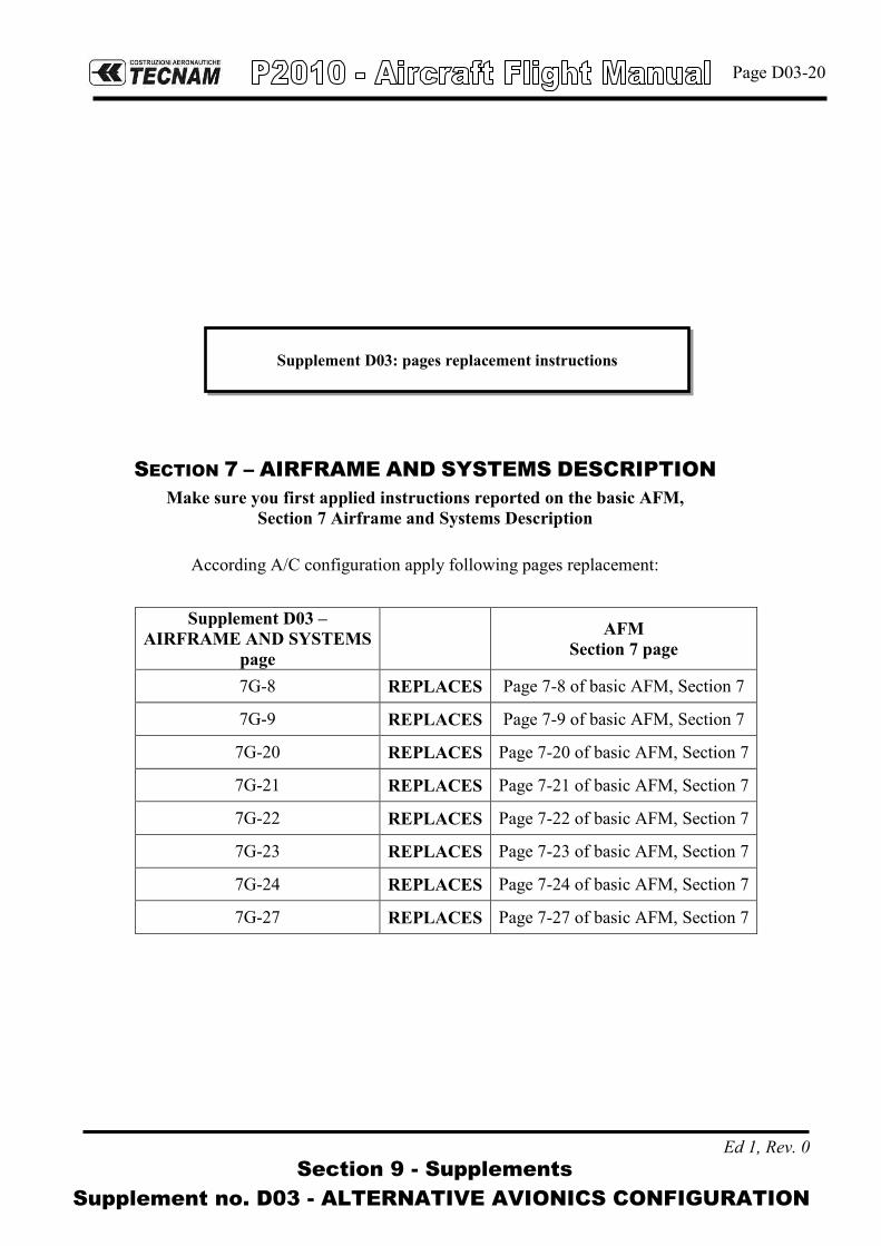
Page D03-20
Section 9 - Supplements -
Supplement no. D03 - ALTERNATIVE AVIONICS CONFIGURATION
Ed 1, Rev. 0
SECTION 7 – AIRFRAME AND SYSTEMS DESCRIPTION
Make sure you first applied instructions reported on the basic AFM, Section 7 Airframe and Systems Description
According A/C configuration apply following pages replacement:
Supplement D03 –
AIRFRAME AND SYSTEMS page
AFM Section 7 page
7G-8 REPLACES Page 7-8 of basic AFM, Section 7
7G-9 REPLACES Page 7-9 of basic AFM, Section 7
7G-20 REPLACES Page 7-20 of basic AFM, Section 7
7G-21 REPLACES Page 7-21 of basic AFM, Section 7
7G-22 REPLACES Page 7-22 of basic AFM, Section 7
7G-23 REPLACES Page 7-23 of basic AFM, Section 7
7G-24 REPLACES Page 7-24 of basic AFM, Section 7
7G-27 REPLACES Page 7-27 of basic AFM, Section 7
Supplement D03: pages replacement instructions

Page D03-21
Section 9 - Supplements -
Supplement no. D03 - ALTERNATIVE AVIONICS CONFIGURATION
Ed 1, Rev. 0
INTENTIONALLY LEFT BLANK

AFMS N°D03 FOR ALTERNATIVE AVIONICS CONFIGURATION
Page 7G-8
Section 7 – Airframe and Systems description
FLIGHT CONTROLS
Ed. 1, Rev. 1
3. FLIGHT CONTROLS
Aircraft flight controls are operated through conventional stick and rudder pedals. Longitudinal control acts through a system of push-rods and is equipped with a trim tab. a cable control circuit is confined within the cabin and it is connected to a pair of push-pull rod systems positioned in each main wing which control ailerons differen-tially. Aileron trimming is carried out on ground through a small tab positioned on left aileron. Flaps are extended via an electric servo actuator controlled by a switch on the in-strument panel. Flaps act in continuous mode; the indicator displays three markings related to 0°, takeoff (T/O) and landing (FULL) positions. A breaker positioned on the right side of the instrument panel protects the electric circuit. The control of the stabilator trim is operated by means of a control wheel, located be-tween the two front seats that acts directly on the control cables. Stabilator trim position is displayed on a dedicated analogue indicator located on the LH area of the instrument panel. Rudder Trimming device for lateral control is provided by means of an electrical ac-tuator controlled by a rocker switch located near the pitch trim wheel; the surface is connected to a potentiometer linked to a rudder trim analogue indicator located on the LH area of the instrument panel.

AFMS N°D03 FOR ALTERNATIVE AVIONICS CONFIGURATION
Page 7G-9
Section 7 – Airframe and Systems description
INSTRUMENTAL PANEL
1st Edition Rev. 1
4. INSTRUMENT PANEL
The instrument panel installed on P2010, when equipped with G500 suite, is present-ed below:
N° 1 Garmin GDU 620 (PFD/MFD), (5); N° 1 Garmin GTN 650 (Com/Nav/Gps), (9); N° 1 Garmin GNC 255A (Com/Nav), (10); N° 1 Garmin GMA 340 (Audio Panel), (8); N° 1 Bendix/King KN 572 (DME unit), (14); N° 1 Bendix/King KR87 (ADF unit), (11); N° 1 JP Instruments EDM 930 (EIS unit), (13); N° 1 JP Instruments EDM 930 Remote Alarm Display, (12); N° 1 Mid-Continent MD-302 (Stand-by Instrument), (6); N° 1 Annunciator panel, (7); N° 1 Pitch trim indicator, (3); N° 1 Rudder trim indicator, (4); N° 1 Chronometer (2);
Fig. 7-8. INSTRUMENT PANEL

AFMS N°D03 FOR ALTERNATIVE AVIONICS CONFIGURATION
Page 7G-20
Section 7 – Airframe and Systems description
ELECTRICAL SYSTEM
Ed. 1, Rev. 0
5. ELECTRICAL SYSTEM
Primary DC power is provided by an external alternator with a 28 VDC output, rated of 70 Amps @ 2700 rpm. During normal operations, it recharges the bat-tery. Secondary DC power is provided by a lead type battery (GILL G-247) which provides the energy necessary for feeding the essential electrical loads in the event of an alternator failure. The switch between the energy sources is automatic and no action is required in order to activate the alternate energy source. For ground maintenance and/or starting, an external power socket is provided. The alternator and battery are connected to the battery bus in order to provide energy for the electric equipment. Each electrically fed instrument is connected to a dedicated circuit breaker which protects the cable from the battery bus to the associated electric equip-ment.
WARNING
If the Ignition is in the position L, R, or BOTH, an accidental movement of the propeller may start the engine with possible danger for bystanders.
In the following figure is presented the electrical system architecture.

AFMS N°D03 FOR ALTERNATIVE AVIONICS CONFIGURATION
Page 7G-21
Section 7 – Airframe and Systems description
ELECTRICAL SYSTEM
Ed. 1, Rev. 0
FIG.7-15. ELECTRICAL SYSTEM ARCHITECTURE
9.1 STALL WARNING SYSTEM
The aircraft is equipped with a stall warning system consisting of a sensor locat-ed on the right wing leading edge connected to a warning horn located near the instrument panel.

AFMS N°D03 FOR ALTERNATIVE AVIONICS CONFIGURATION
Page 7G-22
Section 7 – Airframe and Systems description
ELECTRICAL SYSTEM
Ed. 1, Rev. 0
9.2 AVIONICS
P2010 avionic system, in this equipment configuration, is mainly based on avi-onics package Garmin G500. The G500 suite installed on P2010 is based on a single display layout. It pro-vides the pilot with all primary flight information and is able to act as a naviga-tion indicator for external navigation sources such as VHF NAV and GPS. G500 also presents moving map information to the pilot. Engine parameters are presented on an external instrument, EDM-930, equipped with an additional Remote Alarm Display which is intended to provide RPM and MAP information in the event of primary display failure. An external annunciator panel is located in the top center area of the instrument panel. In order to provide the pilot with main flight information in the event of PFD failure, or in the event of an AHRS and ADC units combined failure, an inte-grated digital stand-by instrument, Mid-Continent MD-302, featuring airspeed, altitude, attitude and slip information is installed. An ELT device is installed and its control switch is located in the upper left area of the cockpit. The Com/Nav functions are embodied into two devices, GNC 255 and GTN 650. The second one provides also GPS signal. A dedicated DME and an dedicated ADF receivers are installed, and also a Tra-sponder unit. Two dedicated analogue indicators are provided for pitch and rudder trim posi-tions. The installed equipment is such that the aircraft is able to fly under day/night VFR and day/night IFR rules and to perform ILS CAT I approaches with ILS.
CAUTION
Standby MD302 has a better availability and integrity than Garmin G500 (at least for the critical parameters) against the HIRF/IEL threats. In case of inconsistency between Garmin PFD and MD-302SAM flight in-formations, it may be expected MD-302SAM to be more reliable, but cross-check with other flight parameters will be necessary to address the faulty source of information.
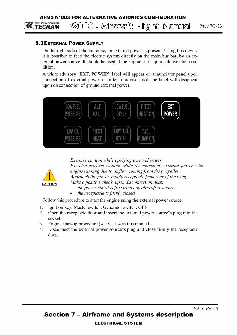
AFMS N°D03 FOR ALTERNATIVE AVIONICS CONFIGURATION
Page 7G-23
Section 7 – Airframe and Systems description
ELECTRICAL SYSTEM
Ed. 1, Rev. 0
9.3 EXTERNAL POWER SUPPLY
On the right side of the tail cone, an external power is present. Using this device it is possible to feed the electric system directly on the main bus bar, by an ex-ternal power source. It should be used at the engine start-up in cold weather con-dition. A white advisory “EXT. POWER” label will appear on annunciator panel upon connection of external power in order to advise pilot; the label will disappear upon disconnection of ground external power.
CAUTION
Exercise caution while applying external power. Exercise extreme caution while disconnecting external power with engine running due to airflow coming from the propeller. Approach the power supply receptacle from rear of the wing. Make a positive check, upon disconnection, that: - the power chord is free from any aircraft structure - the receptacle is firmly closed.
Follow this procedure to start the engine using the external power source. 1. Ignition key, Master switch, Generator switch: OFF 2. Open the receptacle door and insert the external power source‟s plug into the
socket 3. Engine start-up procedure (see Sect. 4 in this manual) 4. Disconnect the external power source‟s plug and close firmly the receptacle
door.

AFMS N°D03 FOR ALTERNATIVE AVIONICS CONFIGURATION
Page 7G-24
Ed. 1Rev 0 Section 7 – Airframe and Systems description
PITOT-STATIC PRESSURE SYSTEMS
10. PITOT-STATIC PRESSURE SYSTEMS
The P2010 air speed/altitude indicating systems are connected with a Pitot-Static system based on a total pressure/Pitot probe (simple Pitot tube, heated for icing protection) mounted on left wing strut and two static pressure ports connected in parallel and located in correspondence of engine firewall on left and right side of fuselage. Flexible hoses connects total pressure and static ports to primary ana-logue instruments, anemometer and altimeter. Garmin G500 suite and standby MD 302 unit are connected to both static and to-tal pressure lines providing both air speed and altitude information.
0°
T/O
LND
FLAP
LH STATIC PORT RH STATIC PORT
"T" JOINT
ALTERNATE STATIC PORT
ALTERNATE STATIC PORT VALVE
GARMIN G500
GDC 74A
ADC
MD-302
G500
0°
T/O
LND
FLAP
GDC 74A
ADC
G500
12
4
3
Pos. Description
1
2
3
4
Pitot
"T" Joint
Garmin G500 connection
MD-302 FIG.7-16. PITOT-STATIC SYSTEM
Legend: Static line Total line

AFMS N°D03 FOR ALTERNATIVE AVIONICS CONFIGURATION
Page 7G-27
Ed. 1Rev 0 Section 7 – Airframe and Systems description
LIGHTS
11.2 INTERNAL LIGHTS
On the cabin ceiling are located four map lights, two in the front area (pilot) and two in the rear area (passengers). In the central area of the cabin ceiling is located a spot light used to illuminate the pedestal during night flight operations. All ceiling lights are dimmable by a dedicat-ed dimmer.
FIG.7-18. CABIN CEILING LIGHTS LAYOUT
The instrument panel can be illuminated by 8 incandescence light strips, all dimma-ble.
FIG.7-19. INSTRUMENT PANEL LIGHTS LAYOUT
FWD
From mid MAP light (ceiling)

Page D03-22
Ed. 1Rev 0 Section 9 - Supplements -
Supplement no. D03 - ALTERNATIVE AVIONICS CONFIGURATION
SECTION 8 – GROUND HANDLING & SERVICE
Make sure you first applied instructions reported on the basic AFM, Section 8 Ground Handling & Service
Refer to the basic AFM, Section 8 – Ground Handling & Service
Supplement D03: pages replacement instructions

Page D03-23
Ed. 1Rev 0 Section 9 - Supplements -
Supplement no. D03 - ALTERNATIVE AVIONICS CONFIGURATION
INTENTIONALLY LEFT BLANK

Page D5-1
Supplements no. D5
Supplement no. D5 – Argentine AFM supplement
1st Edition, Rev. 0
SUPPLEMENT NO. D5
ARGENTINE AIRCRAFT FLIGHT MANUAL SUPPLEMENT
Record of Revisions
Rev Revised page
Description of Revision
Tecnam Approval EASA Approval or Under DOA
Privileges DO OoA HDO
0 - D. Ronca M.Oliva M. Oliva DOA
List of Effective Pages
Page Revision Page Revision D5-1 Rev 0 D5-2 Rev 0 D5-3 Rev 0 D5-4 Rev 0 D5-5 Rev 0 D5-6 Rev 0 D5-7 Rev 0

Page D5-2
Supplements no. D5
Supplement no. D5 – Argentine AFM supplement
1st Edition, Rev. 0
INDEX
INTRODUCTION ..................................................................................... 3
LIMITATION ........................................................................................................ 3
Limitation placards ............................................................................................. 3
Other placards .................................................................................................... 4

Page D5-3
Supplements no. D5
Supplement no. D5 – Argentine AFM supplement
1st Edition, Rev. 0
INTRODUCTION
This supplement contains supplementary information for a safe and efficient operation of the aircraft delivered in the Argentina For limitations, procedures, and performance information not contained in this supple-ment, refer to the EASA Approved Aircraft Flight Manual.
LIMITATION
The information contained herein complements or supersedes the basic information in the EASA Approved Aircraft Flight Manual.
LIMITATION PLACARDS
On the right side of the instrument panel the following placard is placed reminding the observance for “NO FUMAR”:
Behind the baggage compartment door the following placard is placed:

Page D5-4
Supplements no. D5
Supplement no. D5 – Argentine AFM supplement
1st Edition, Rev. 0
OTHER PLACARDS
Door Placard
Baggage Door
Internal door Placard

Page D5-5
Supplements no. D5
Supplement no. D5 – Argentine AFM supplement
1st Edition, Rev. 0
Emergency Exit internal placard
Open baggage placard
Door Handle locking
Or

Page D5-6
Supplements no. D5
Supplement no. D5 – Argentine AFM supplement
1st Edition, Rev. 0
External Power Socket and baggage compartment placards
Static source placards
No Step placard
Fuel Limitation placard

Page D5-7
Supplements no. D5
Supplement no. D5 – Argentine AFM supplement
1st Edition, Rev. 0
Safety equipment location placard
ELT placard

Section 9 – Supplements- Supplement no. D07
GARMIN GFC700 AUTOPILOT AND VARIABLE PITCH PROPELLER EQUIPPED AEROPLANES
Page D07-1
Ed. 1, Rev. 0
Supplement no. D07-
AFMS FOR GARMIN GFC700 AUTOPILOT AND VARIABLE PITCH PROPELLER
EQUIPPED AEROPLANES
Record of Revisions
Rev Revised page
Description of Revision
Tecnam Approval EASA Approval or Under DOA
Privileges DO OoA HDO
0 - First Issue D. Ronca C. Caruso M. Oliva
List of Effective Pages
Page Revision
Cover Pages D07-1 thru 21 Rev. 0
Section 1 APV 1-6, APV 1-13, APV 1-16 thru 31 Rev. 0
Section 2 APV 2-7, APV 2-9 thru 10, APV 2-15, APV 2-17 thru 20 Rev. 0
Section 3 APV 3-14, APV 3-18 thru 19, APV 3-31 thru 35 Rev. 0
Section 4 APV 4-7, APV 4-15, APV 4-19 thru 26, APV 4-27 thru 38 Rev. 0
Section 5 APV 5-1 thru 16 Rev. 0
Section 6 APV 6-11 thru 12 Rev. 0
Section 7 APV 7-8 thru 11, APV 7-16, APV 7-20 thru 21, APV 7-27, APV 7-33, APV 7-36 Rev. 0

Section 9 – Supplements- Supplement no. D07
GARMIN GFC700 AUTOPILOT AND VARIABLE PITCH PROPELLER EQUIPPED AEROPLANES
Page D07-2
Ed. 1, Rev. 0
INDEX
INDEX ..................................................................................................... 2
INTRODUCTION ..................................................................................... 3
Section 1 – GENERAL ............................................................................ 5
Section 2 – LIMITATIONS ...................................................................... 7
Section 3 – EMERGENCY PROCEDURES ............................................... 9
Section 4 – NORMAL PROCEDURES ................................................... 11
Section 5 – PERFORMANCE ................................................................ 13
Section 6 – WEIGHT AND BALANCE ................................................... 15
Section 7 – AIRFRAME AND SYSTEMS DESCRIPTION ....................... 17
Section 8 – GROUND HANDLING & SERVICE ..................................... 19

Section 9 – Supplements- Supplement no. D07
GARMIN GFC700 AUTOPILOT AND VARIABLE PITCH PROPELLER EQUIPPED AEROPLANES
Page D07-3
Ed. 1, Rev. 0
INTRODUCTION
This section contains supplemental information to operate, in a safe and efficient manner, the aircraft when equipped with Garmin GFC 700 autopilot device in-terfacing Garmin G1000 and MT variable pitch propeller. It is the owner’s responsibility to replace the mentioned pages in accordance with the instructions herein addressed section by section.

Section 9 – Supplements- Supplement no. D07
GARMIN GFC700 AUTOPILOT AND VARIABLE PITCH PROPELLER EQUIPPED AEROPLANES
Page D07-4
Ed. 1, Rev. 0
INTENTIONALLY LEFT BLANK
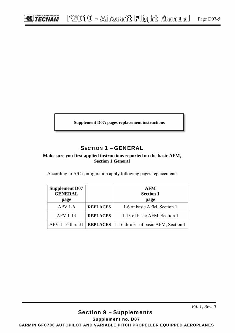
Section 9 – Supplements- Supplement no. D07
GARMIN GFC700 AUTOPILOT AND VARIABLE PITCH PROPELLER EQUIPPED AEROPLANES
Page D07-5
Ed. 1, Rev. 0
SECTION 1 – GENERAL Make sure you first applied instructions reported on the basic AFM,
Section 1 General
According to A/C configuration apply following pages replacement:
Supplement D07 GENERAL
page
AFM Section 1
page APV 1-6 REPLACES 1-6 of basic AFM, Section 1
APV 1-13 REPLACES 1-13 of basic AFM, Section 1
APV 1-16 thru 31 REPLACES 1-16 thru 31 of basic AFM, Section 1
Supplement D07: pages replacement instructions

Section 9 – Supplements- Supplement no. D07
GARMIN GFC700 AUTOPILOT AND VARIABLE PITCH PROPELLER EQUIPPED AEROPLANES
Page D07-6
Ed. 1, Rev. 0
INTENTIONALLY LEFT BLANK

Section 1 – General
GENERAL FEATURES
5. ENGINE
Manufacturer …………………………… Lycoming Engines Model …………………………………... IO-360-M1A Type Certificate ………………………... EASA TCDS no. IM.E.032 Engine type …………………………….. Fuel injected (IO), direct drive, four cylinder
horizontally opposed, air cooled with down exhaust outlets.
Maximum power ……. Maximum continuous power …………...
134.0 kW (180hp) @ 2700 rpm 129.2 kW (173.3hp) @ 2600 rpm
6. PROPELLERManufacturer ………………………….. MT PropellerModel …………………………………. MTV-15-B/193-52Type Certificate ……………………….. EASA TCDS no. P.098Blades/hub …………………………….. wood/composite 2-blades – aluminum hubDiameter ………………………………. 1930 mm (76 in) (no reduction is permitted)Type …………………………………… Variable pitch
GovernorManufacturer ………………………….. MT PropellerModel …………………………………. P-860-23:Type ……………………….. Hydraulic
AFMS N°D07 FOR GARMIN GFC700 AUTOPILOT AND VARIABLE PITCH PROPELLER EQUIPPEDAEROPLANES
Page APV 1-6
1st Edition, Rev. 0

Section 1 – General ACRONYMS AND TERMINOLOGY
Autopilot acronyms AC Advisory Circular GNSS Global Navigation Satellite System
A/C Aircraft GP Glide Path
ADC Air Data Computer GPS Global Position System
ADF Automatic Direction Finder GS Glide Slope
ADI Attitude Directional Indicator GSA Garmin Servo Actuator
AFCS Automatic Flight Control Systyem GSM Garmin Servo Mount
AHRS Attitude Heading Reference System HDG Heading
ALT Altitude HSDB High Speed Data Bus
ALTS Altitude Selector IAU Integrated Avionic Unit
AMPS Ampere LOC Localizer
A/P Autopilot LRU Line Repleaceable Unit
APR Approach LVL Level
ARP Aerospace Recommended Practice MAG Magnetometer
ASI Air Speed Indicator MET Manual Electric Trim
BC Back Course MFD Multi-Function Display
CAS Caution Advisory System NAV Navigation
CDI Course Deviation Indicator OAT Outside Air Temperature
CS Certification Specifications PFD Primary Flight Display
CWS Control Wheel steering PFI Primary Flight Information
DC Direct Current PFT Pre Flight Test
DME Distance Measuring Equipment PWM Pulse Width Modulation
EIS Engine Indication System SAE SAE International
ESP Electronic Stability and Protection TDM Time Division Multiplexing
FD Flight Director USP Under Speed Protection
FLC Flight Level Change VHF Very-High Frequency
GA Go Around VNV Vertical Navigation
GDU Garmin Display Unit VS Vertical Speed
GIA Garmin Integrated Avionics XPDR Transponder
AFMS N°D07 FOR GARMIN GFC700 AUTOPILOT AND VARIABLE PITCH PROPELLER EQUIPPEDAEROPLANES
Page APV 1-13
1st Edition, Rev. 0
Section 1 – General AUTOPILOT DESCRIPTION
AUTOPILOT DESCRIPTION 12P2010 aircraft is equipped, as an optional equipment, with an integrated 2-axis au-topilot suite manufactured by Garmin and identified as GFC 700. This autopilot suite was designed as an option for the G1000 integrated flight deck. The autopi-lot is controlled via dedicated keys grouped in a control panel located on the MFD. The installed MFD display is different with respect to standard P2010 con-figuration since it is GDU 1044. The autopilot suite installed on P2010 is based on the following configuration:
• 1 Roll servo • 1 Pitch servo • 1 Pitch Trim servo
Neither yaw axis nor rudder trim tab control is provided. The autopilot is connected to electric system through the below listed circuit breakers connected to the avionics bus:
1) A/P (5A) 2) PITCH TRIM (3A)
The installed servos are capstan type and are composed of two main components: • A servo motor • A servo capstan including the servo clutch
The following block diagram describes the avionic system installed on P2010 and its interconnections with the autopilot servos:
AFMS N°D07 FOR GARMIN GFC700 AUTOPILOT AND VARIABLE PITCH PROPELLER EQUIPPEDAEROPLANES
Page APV 1-16
1st Edition, Rev. 0

Section 1 – General AUTOPILOT DESCRIPTION
PFD MFDAUDIOPANEL
ADC
AHRS
MAG.
EIS
XPDR
IAU 1 IAU 2
HSDB
RS-485 RS-485
RS-232
ARINC 429 ARINC 429
ARINC 429
RS-232RS-485
ARINC 429 ARINC 429
OAT
MASTERCONFIG.MODULE
CONFIG.MODULE
CONFIG.MODULE
CONFIG.MODULE
RS-232ARINC 429RS-232ARINC 429
RS-232ARINC 429
ARINC 429
REVERSIONARY SWITCHREVERSIONARY SWITCH
RS-232
RS-232RS-232
DME
ADF
HSDB
MD-302STAND-BY
INSTR.
STATICPRESSURE
PORT
TOTALPRESSURE
PORT
STATIC PRESSURETOTAL PRESSURE
HSDB
ROLLSERVO
PITCHSERVO
PITCHTRIM
SERVO
RS-485
RS-485
The multifunction display (MFD) provides the pilot with a dedicated set of keys for autopilot control (see red frame in the below picture).
The roll servo is located under the pilot seat and is fixed to a/c structure using a dedicated mount. Pitch and pitch trim servos are located in the tail cone and are installed on a dedicated mount which hosts both the servos.
AFMS N°D07 FOR GARMIN GFC700 AUTOPILOT AND VARIABLE PITCH PROPELLER EQUIPPEDAEROPLANES
Page APV 1-17
1st Edition, Rev. 0

Section 1 – General AUTOPILOT DESCRIPTION
GFC 700 is an integrated autopilot since it uses several information provided by other units embodied in the G1000 avionics suite in order to compute the maneu-vers to be performed by the aeroplane and actuate them. The below table lists the functions which are required in order to have the GFC 700 operational and the G1000 LRUs responsible for providing it:
LRU Function
PFD/MFD (GDU 104X)
ADC (GDC 74X)
AHRS (GRS 77)
MAG. (GMU 44)
IAU1/2 (GIA 63W)
ACTUA-TOR (GSA 8X)
CAP-STAN (GSM 8X)
AFCS mode select buttons
Display of the AFCS mode annuncia-tions and flight director command bars.
(PFD NORMAL) (MFD REVER-
SIONARY)
Attitude/Heading information Air data information Navigational database Parameters GPS/WAAS, VOR, and ILS naviga-tional data
Mode logic, flight director computa-tions, and servo management
Autopilot computations and monitor-ing
Aircraft control surface Actuation
Trim functionality
In control of the roll axis, the autopilot senses turn rate, as well as closure rate to the selected course, along with the non-rate quantities of heading error, course er-ror and course deviation indication. In control of the pitch axis, the autopilot senses vertical speed, acceleration, and closure rate to the selected glideslope, along with the non-rate quantities of alti-tude and glideslope deviation indication. The “autotrim” function senses when the aircraft needs to be trimmed about the pitch axis, and responds by driving the trim servo in the proper direction to pro-vide trim.
1st Edition, Rev. 0
AFMS N°D07 FOR GARMIN GFC700 AUTOPILOT AND VARIABLE PITCH PROPELLER EQUIPPEDAEROPLANES
Page APV 1-18

Section 1 – General AUTOPILOT DESCRIPTION
12.1 GDU 1044 (MFD) GDU 1044 MFD unit can display as default engine parameters and moving map information, along with other information that can be selected by the pilot (see the first figure below); when reversionary mode is active it will display flight parame-ters (in the form of PFD with the left strip engine information, as can be seen in the second figure below). It is the user interface for P2010 avionics suite. GDU 1044 unit replaces the GDU 1040 unit on instrument panel RH side (MFD).
GDU 1044 (MFD)
Reversionary mode: - In the event of a single display failure the system is able to automatically
switch the critical information including flight and engine parameters on the remaining display presenting them in a compact view. In the event of a failure of the automatic switch logic, the pilot can easily force the reversionary mode by pressing the red button on the bottom of the audio panel thus getting both flight and engine parameters information, necessary for continued safe flight, on the remaining display.
GDU 1044 (MFD) in reversionary mode
1st Edition, Rev. 0
AFMS N°D07 FOR GARMIN GFC700 AUTOPILOT AND VARIABLE PITCH PROPELLER EQUIPPEDAEROPLANES
Page APV 1-19

Section 1 – General AUTOPILOT DESCRIPTION
Autopilot control panel The GDU1044 includes a set of additional softkeys dedicated to the control of Autopilot system. The following dedicated AFCS keys are located on the bezel of the MFD (refer picture below):
1) AP Key: Engages/ disengages the autopilot 2) FD Key: Activates/deactivates the flight director only 3) NAV Key: Selects/deselects Navigation Mode 4) ALT Key: Selects/deselects Altitude Hold Mode 5) VS Key: Selects/deselects Vertical Speed Mode 6) FLC Key: Selects/deselects Flight Level Change Mode 7) HDG Key: Selects/deselects Heading Select Mode 8) APR Key: Selects/deselects Approach Mode 9) VNV Key: Selects/deselects Vertical Path Tracking Mode for Vertical
Navigation flight control 10) NOSE UP/ NOSE DN Keys: Control the mode reference in Pitch Hold,
Vertical Speed and Flight Level Change modes
Autopilot control panel
1st Edition, Rev. 0
AFMS N°D07 FOR GARMIN GFC700 AUTOPILOT AND VARIABLE PITCH PROPELLER EQUIPPEDAEROPLANES
Page APV 1-20

Section 1 – General AUTOPILOT DESCRIPTION
12.2 PILOT CONTROL WHEEL AND THROTTLE BUTTONS On the left side of pilot’s and copilot’s control wheels there are two PTT switches (the one on pilot control wheel is shown below as (1)) that, when pushed, allow radio transmission. These switches are momentaneous ones thus acting in such a way that when they are released the active COM device returns to the non-transmitting state. These switches are already installed in the basic aircraft which is not equipped with the autopilot. The following additional dedicated AFCS controls are located on the pilot control wheel, separately from the MFD, and on the throttle handle:
AP DISC Switch: Disengages the autopilot and interrupts pitch trim operation
This switch may be used to mute the aural autopilot disconnect alert.
AP Trim Switch: Used to command manual electric trim. This composite switch is split into left and right sides. The left switch is the ARM contact and the right switch controls the DN (forward) and UP (rearward) contacts. The AP TRIM ARM switch can be used to disengage the autopilot and to acknowledge an autopilot dis-connect alert and mute the associated aural tone. Manual trim commands are generated only when both sides of the switch are operated simultaneously. If either side of the switch is ac-tive separately for more than three seconds, MET function is disabled and ‘PTRM’ is displayed as the AFCS Status Annun-ciation on the PFD. The function remains disabled until both sides of the switch are inactivated.
CWS Button: While pressed, the Control Wheel Steering allows manual con-trol of the aircraft while the autopilot is engaged and synchro-nizes the flight director’s Command Bars with the current air-craft pitch (if not in Glideslope Mode) and roll (if in Roll Hold Mode). Upon release of the CWS Button, the flight director may establish new reference points, depending on the current pitch and roll modes. CWS operation details are discussed in the flight director modes section.
TO/GA Switch: The GA Switch is located on the throttle handle. Go Around and Takeoff modes are coupled pitch and roll modes and are annunciated as both the vertical and lateral modes when active. In these modes, the flight director commands a constant set pitch attitude and keeps the wings level. The GA Switch is used to select both modes. The mode entered by the flight director depends on wheth-er the aircraft is on the ground.
1st Edition, Rev. 0
AFMS N°D07 FOR GARMIN GFC700 AUTOPILOT AND VARIABLE PITCH PROPELLER EQUIPPEDAEROPLANES
Page APV 1-21

Section 1 – General AUTOPILOT DESCRIPTION
The above mentioned AFCS controls are depicted in the below figures.
where:
1) PTT switch 2) AP DISC Switch 3) AP Trim Switch 4) CWS Button
1st Edition, Rev. 0
AFMS N°D07 FOR GARMIN GFC700 AUTOPILOT AND VARIABLE PITCH PROPELLER EQUIPPEDAEROPLANES
Page APV 1-22

Section 1 – General AUTOPILOT DESCRIPTION
1st Edition, Rev. 0
AFMS N°D07 FOR GARMIN GFC700 AUTOPILOT AND VARIABLE PITCH PROPELLER EQUIPPEDAEROPLANES
Page APV 1-23

Section 1 – General AUTOPILOT FUNCTIONS
AUTOPILOT FUNCTIONS AND FEATURES 13GFC 700 autopilot suite is deeply integrated with Garmin G1000 avionics suite which integrates both the a/p controls and the sensors providing the required data to the servos. The GFC 700 AFCS is equipped with the following main operating functions:
• Flight Director (FD) — Flight director commands are displayed on the PFD. The
flight director provides: Command Bars showing pitch/roll guidance Pitch/roll mode selection and processing Autopilot communication
• Autopilot (AP) — Autopilot operation occurs within the pitch, roll, and pitch
trim servo and provides servo monitoring and automatic flight control in response to flight director steering commands, AHRS attitude and rate information, and air-speed.
• Manual Electric Trim (MET) — The pitch trim servo provides manual electric
trim capability when the autopilot is not engaged.
• ESP (Electronic Stability & Protection) keeps the aircraft within well defined op-erational limits thus preventing the pilot to operate the aircraft outside a specific envelope when it is being hand flown. This feature only operates when autopilot is not engaged and its operation is mutually exclusive with autopilot operation.
• USP (Underspeed Protection) is a flight director function that reacts to under-speed conditions in a way that allows the autopilot to remain engaged but prevents the airplane from stalling.
1st Edition, Rev. 0
AFMS N°D07 FOR GARMIN GFC700 AUTOPILOT AND VARIABLE PITCH PROPELLER EQUIPPEDAEROPLANES
Page APV 1-24

Section 1 – General AUTOPILOT FUNCTIONS
13.1 ESP Garmin GFC 700 is equipped with an envelope protection feature referred as ESP (Electronic Stability & Protection). Electronic Stability and Protection continu-ously monitors the aircraft. The system works by applying a correcting force to the controls in order to nudge pilot to avoid extreme attitudes that may bring the aircraft, if not corrected, to exceed normal flying envelope. This software feature aims to provide protection against aircraft operation outside a desired flight envelope. ESP will maintain the desired operating envelope, de-fined at autopilot development time, by automatically engaging one or more ser-vos when the aircraft is near the operating limit and nudging pilot to come back to nominal operating envelope. While ESP utilizes the same sensors, processors, and actuators as the GFC 700 autopilot, it is basically a separate function. ESP can be overpowered by the pilot and can be temporarily disabled using the AP disconnect or CWS switches. It functions independently of the aircraft’s autopilot system (although it uses the same control servos), so it basically operates “in back-ground” whenever the pilot is hand-flying the airplane. The ESP feature will only function with GPS available, A/P MASTER SWITCH ON (but autopilot not engaged) and aircraft above 200ft AGL.
ESP enabling:
As a standard, ESP will automatically set to enable at power-up. The system is configured in order to allow the pilot to disable ESP (or re-enable it if previously disabled after power up) via the AUX – SYSTEM SETTINGS page on MFD. If ESP has been disabled via MFD, it will automatically be set to ON upon any battery/power reset. ESP function uses the same servos that provide autopilot functionality while auto-pilot is not engaged, as such, if power is cut from these servos both autopilot and ESP functions will be unavailable. Based on the above if “AUTOPILOT MASTER” is set to OFF, power to servos is cut irrespectively of their mode of operation (autopilot or ESP). The pilot can interrupt ESP by pressing and holding either the Control Wheel Steering (CWS) or Autopilot Disconnect (AP DISC TRIM INTRPT) switch. Up-on releasing the CWS or AP DISC TRIM INTRPT switch, ESP force will again be applied, provided aircraft attitude and/or airspeed are within their respective engagement limits. ESP can be enabled or disabled on the AUX-SYSTEM SETUP 2 Page on the MFD.
1st Edition, Rev. 0
AFMS N°D07 FOR GARMIN GFC700 AUTOPILOT AND VARIABLE PITCH PROPELLER EQUIPPEDAEROPLANES
Page APV 1-25

Section 1 – General AUTOPILOT FUNCTIONS
To enable or disable ESP:
1) Turn the large FMS Knob to select the AUX Page Group. 2) Turn the small FMS Knob to select the System Setup Page. 3) If necessary, select the SETUP 2 Softkey to display the AUX-SYSTEM
SETUP 2 Page.If the AUX-SYSTEM SETUP 2 is already displayed, pro-ceed to step 4.
4) Press the FMS Knob to activate the cursor. 5) Turn the large FMS Knob to place cursor in the STABILITY & PRO-
TECTION field. 6) Turn the small FMS Knob to select ‘ENABLE’ or ‘DISABLE’. 7) Press the FMS Knob to remove the cursor.
ESP engagement and operation:
ESP is automatically enabled on system power up.
ESP unavailability and/or failure is indicated to the pilot on PFD by the advisory “ESP not available” on alert window.
ESP will turn OFF upon loss of both GPS. The ADVSY “ESP OFF” will appear on the alert window in case of loss of both GPS.
13.1.1 PITCH MODE Pitch attitude boundaries are set based on P2010 aircraft performances. Since pitch ESP augments the natural aircraft longitudinal stability, no special simbolo-gy is required. Value that have been set-up for the P2010 are as follows:
Nose above the horizon: Engagement low threshold: + 15° Engagement upper threshold: + 18° Lower disengage threshold: + 12°
Nose below the horizon: Engagement low threshold: -15° Engagement upper threshold: -20° Lower disengage threshold: -13°
ESP utilizes electronic torque and speed commands to augment the aircraft’s sta-bility: it uses an Electronic Torque Limit (ETL) and an Electronic Speed Limit (ESL) to limit the maximum authority of the ESP function. ESP is inactive when the pitch attitude is within the positive and negative engagement limits defined in the certification gain file.
NOTE
NOTE
1st Edition, Rev. 0
AFMS N°D07 FOR GARMIN GFC700 AUTOPILOT AND VARIABLE PITCH PROPELLER EQUIPPEDAEROPLANES
Page APV 1-26

Section 1 – General AUTOPILOT FUNCTIONS
When the aircraft reaches the engagement limit, ESP ramps up the servo torque command to adjust the aircraft back toward zero pitch attitude. ESP uses a rate command to drive the attitude back to the nominal range and does not try to con-trol to a specific attitude. As the pitch attitude returns to the nominal range, the torque and pitch rate are reduced until the aircraft reaches the disengagement limit at which time ESP turns off. The disengagement threshold is sized so that the transition from ESP being active to being inactive is transparent to the pilot (no transient when ESP turns off). If, when ESP engages, the aircraft continues to pitch away from the nominal atti-tude range the torque command will increase with increasing pitch deviation. Above the upper disengagement limit specified in the certification gain file ESP will be disabled.
13.1.2 ROLL MODE Roll mode is similar to pitch mode and also utilizes configurable gain file parame-ters to define engagement and disengagement limits as well as the speed and torque curves. The engagement and disengagement attitude limits are displayed with double hash marks on the roll indicator when ESP is available and /or active. The lack of dou-ble hash marks above 200 ft AGL (when autopilot is not connected) is a clear in-dication that ESP is not available. Values for the symmetric roll attitude limits are as follows:
Engagement low threshold: +/- 45° Engagement upper threshold: +/- 75° Lower disengage threshold: +/- 30°
Electronic stability and protection action starts at the predetermined bank angle. Since crossing this bank angle results in a change in aircraft stability (and there-fore handling characteristics) indications of this boundary are provided to the pi-lot.
When ESP is inactive (roll attitude within nominal limits) only the engagement limits are displayed in order to reduce clutter on the roll indicator. As the bank
1st Edition, Rev. 0
AFMS N°D07 FOR GARMIN GFC700 AUTOPILOT AND VARIABLE PITCH PROPELLER EQUIPPEDAEROPLANES
Page APV 1-27

Section 1 – General AUTOPILOT FUNCTIONS
angle is increased, a region of an increasing force as a function of bank angle is entered. The envelope protection system adds bank stability in this region. As the bank angle is increased further, a constant force is applied to right the airplane. See the below figure for an example of the ESP engagement limits.
VMO Exceeding VMO will result in ESP applying force to raise the nose; when the high speed condition is remedied, ESP force is no longer applied.
Engage Limit: 165 KIAS Upper Limit: 168 KIAS Lower disengage Limit: 160 KIAS
13.2 USP Underspeed Protection (USP) is a flight director function that reacts to underspeed conditions, designed to discourage aircraft operation below minimum established airspeeds. Pilot will be warned of impending low speed conditions, and if no action will be taken FD will directly react in a way that allows the A/P to remain engaged but prevents the airplane from stalling.
WARNING
USP function has been developed in order to warn pilot of impending low speed conditions, and if no action will be taken FD will directly react in a way that allows the Autopilot to remain engaged but pre-vents the airplane from stalling. Pilot action is still expected at first warning of low airspeed conditions in order to prevent a low speed conditions, so to maintain normal flight.
CAUTION
When autopilot is engaged USP will provide the pilot with au-ral/visual cues to make him aware of an impending stall and will drive the servos in order to prevent stall. When autopilot is not engaged and only Flight director is active, USP will provide the pilot with aural/visual cues to make him aware of an impending stall but servos will not be driven.
1st Edition, Rev. 0
AFMS N°D07 FOR GARMIN GFC700 AUTOPILOT AND VARIABLE PITCH PROPELLER EQUIPPEDAEROPLANES
Page APV 1-28

Section 1 – General AUTOPILOT FUNCTIONS
How Underspeed Protection functions depends on which vertical flight director mode is selected. For the purpose of this discussion, the vertical flight director modes can be divid-ed into two categories:
- It is important to maintain altitude for as long as possible (altitude-critical modes).
- Maintaining altitude is less crucial (non-altitude critical modes).
CAUTION
If USP engages while Autopilot is in PIT or VS mode, and power is ab-ruptly set to full throttle, pilot may expect a slight nose up tendency that will be quickly counteracted by autopilot. This is a normal behaviour, the slight nose up tendency in this case will be due to abrupt power advance, but will be immediately damped by Autopilot (with PIT or VS turning green on the annunciation panel).
CAUTION
USP engagement is a consequence of autopilot failing to properly moni-toring A/P and aircraft behaviour. This is mainly caused by a pilot re-quest that cannot be fulfilled due to lack of power coupled with unattain-able pitch input. Pilot need to continuously monitor autopilot performance, while checking that mode selections are compatible with aircraft performance.
CAUTION
If Autopilot is engaged in FLC mode, FLC mode will downgrade to PIT mode when in USP for more than 10 seconds.
CAUTION
If USP engages while in ALT mode, upon USP disengagement FD will com-mand bars to regain pre-selected altitude (altitude selected before USP en-gagement). Pilot must monitor A/P to check if previous pre-selected altitude is still attainable with energy available. It is recommended in this case to pre-select a new altitude in order to speed-up energy management and recover from slow speed conditions.
When USP becomes active, expect a small FD adjustment due to reaction to very low speed condition.
NOTE
1st Edition, Rev. 0
AFMS N°D07 FOR GARMIN GFC700 AUTOPILOT AND VARIABLE PITCH PROPELLER EQUIPPEDAEROPLANES
Page APV 1-29

Section 1 – General AUTOPILOT FUNCTIONS
13.2.1 ALTITUDE CRITICAL MODES (ALT, GS, GP, TO, GA, FLC)
When the airspeed trend vector (dedicated algorithm) reaches 65 +/- 2 KIAS a single aural “AIRSPEED” will sound, alerting the pilot to the impending under-speed condition, which requires pilot action. If the aircraft decelerates to stall warning and a speed of 65 KIAS is reached, the lateral and vertical flight director modes will change from active to armed and the autopilot will provide input causing the aircraft to pitch down and the wings to level.
The aural “AIRSPEED” alert will sound every five seconds. If aircraft is unintentionally decelerated to 65 KIAS, a MINSPD annunciation posts above the airspeed tape on PFD in alternating amber and black text. A red “UNDERSPEED PROTECT ACTIVE” annunciation will appear to the right of the vertical speed indicator. USP will drive the pitch down until the indicated air-speed increases above 70 KIAS or stall warning turns off, plus two knots (which-ever comes first). When USP disengages, autopilot will cause the aircraft to pitch up until recaptur-ing the vertical reference (vertical and lateral flight director modes will change from white armed to green active).
1st Edition, Rev. 0
AFMS N°D07 FOR GARMIN GFC700 AUTOPILOT AND VARIABLE PITCH PROPELLER EQUIPPEDAEROPLANES
Page APV 1-30
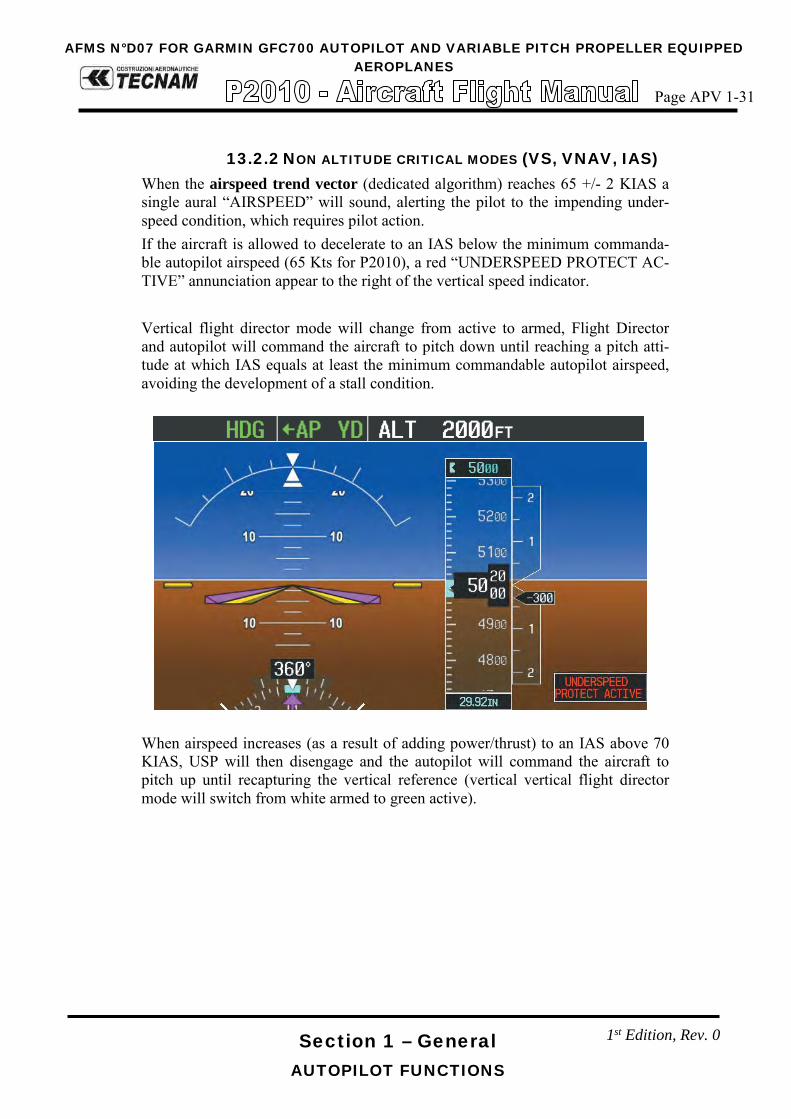
Section 1 – General AUTOPILOT FUNCTIONS
13.2.2 NON ALTITUDE CRITICAL MODES (VS, VNAV, IAS) When the airspeed trend vector (dedicated algorithm) reaches 65 +/- 2 KIAS a single aural “AIRSPEED” will sound, alerting the pilot to the impending under-speed condition, which requires pilot action. If the aircraft is allowed to decelerate to an IAS below the minimum commanda-ble autopilot airspeed (65 Kts for P2010), a red “UNDERSPEED PROTECT AC-TIVE” annunciation appear to the right of the vertical speed indicator. Vertical flight director mode will change from active to armed, Flight Director and autopilot will command the aircraft to pitch down until reaching a pitch atti-tude at which IAS equals at least the minimum commandable autopilot airspeed, avoiding the development of a stall condition.
When airspeed increases (as a result of adding power/thrust) to an IAS above 70 KIAS, USP will then disengage and the autopilot will command the aircraft to pitch up until recapturing the vertical reference (vertical vertical flight director mode will switch from white armed to green active).
1st Edition, Rev. 0
AFMS N°D07 FOR GARMIN GFC700 AUTOPILOT AND VARIABLE PITCH PROPELLER EQUIPPEDAEROPLANES
Page APV 1-31

Page D07-7
Section 9 – Supplements- Supplement no. D07
GARMIN GFC700 AUTOPILOT AND VARIABLE PITCH PROPELLER EQUIPPED AEROPLANES
Ed. 1, Rev.0
SECTION 2 – LIMITATIONS Make sure you first applied instructions reported on the basic AFM,
Section 2 Limitations
According to A/C configuration apply following pages replacement:
Supplement D07 LIMITATIONS
page
AFM Section 2
page APV 2-7 REPLACES 2-7 of basic AFM, Section 2
APV 2-9 thru 10 REPLACES 2-9 thru 10 of basic AFM, Section 2
APV 2-15 REPLACES 2-15 of basic AFM, Section 2
APV 2-17 thru 20 REPLACES 2-17 thru 20of basic AFM, Section 2
Supplement D07: pages replacement instructions

Page D07-8
Section 9 – Supplements- Supplement no. D07
GARMIN GFC700 AUTOPILOT AND VARIABLE PITCH PROPELLER EQUIPPED AEROPLANES
Ed. 1, Rev.0
INTENTIONALLY LEFT BLANK

Section 9 – Supplements
Powerplant limitations
4. POWERPLANT LIMITATIONS
Following table reports the operating limitations the installed engine: ENGINE MANUFACTURER: Lycoming Engines ENGINE MODEL: IO-360-M1A MAXIMUM POWER:
Max Power (hp)
Max rpm. Prop. rpm
Max. T.O. 180 2700
Max. Cont. 173.3 2600
Temperatures: Max CHT ……………………………………….. 500° F (260° C) Max Oil …………………………………………. 245° F (118° C) Oil Pressure: Minimum Idling ………………………………… 25 psi (1.7 Bar) Minimum Normal ………………………………. 55 psi (3.8 Bar)
Maximum Normal ……………………………… 95 psi (6.5 Bar) Starting, Warm-up, taxi and take-off (Max) …… 115 psi (7.9 Bar)
Fuel pressure: - At Inlet to fuel injector:
Minimum .............................................................. 14 psi (0.96 Bar) Maximum ............................................................. 35 psi (2.41 Bar)
AFMS N°D07 FOR GARMIN GFC700 AUTOPILOT AND VARIABLE PITCH PROPELLER EQUIPPEDAEROPLANES
Page APV 2-7
1st Edition, Rev. 0

Section 2 – Limitations
PAINT, PROPELLER, MAX ALTITUDE AND OAT
CAUTION
At altitudes above 10000 ft (3048 m) up to and including 12000 ft (3658 m), flight crew is recommended to use supplemental oxygen.
8. AMBIENT TEMPERATURE
Ambient temperature: from -25°C to +50°C.
WARNING
Flight in expected and/or known icing conditions is forbidden.
5. PAINTTo ensure that the temperature of the composite structure does not exceed limits,the outer surface of the aeroplane must be painted with white paint, except for areasof registration marks, placards, and ornament.Refer to Aircraft Maintenance Manual (AMM), ATA Chapter 4 and 51, for specificpaint requirements.
6. PROPELLER
MANUFACTURER: .…….. MT PropellerMODEL: …………….……. MTV 15B/193-52TYPE: .……………….…… wood/composite 2-blade, variable pitchDIAMETER: ……………... 1930 mm (76 in) (no reduction is permitted)
7. MAXIMUM OPERATING ALTITUDE
Maximum operating altitude is 12000 ft (3658 m) MSL.
AFMS N°D07 FOR GARMIN GFC700 AUTOPILOT AND VARIABLE PITCH PROPELLER EQUIPPEDAEROPLANES
Page APV 2-9
1st Edition Rev.0

Section 2 – Limitations
POWERPLANT AND OTHER INSTRUMENT MARKINGS
4. POWERPLANT INSTRUMENT MARKINGS
Powerplant instrument markings and their colour code significance are shown below:
INSTRUMENT
RED ARC Minimum
limit
WHITE ARC Advisory
GREEN ARC Safe
operation
YELLOW ARC Caution
RED ARC Maximum
limit
PROPELLER RPM / / 950-2600 0-950
2600-2700 2700 (line)
OIL TEMP. °F / / 140-245 0 - 140 245 - 255
CHT °F / 435 (line) 150-475 0 – 150 475-500
500-510
EGT °F / 1000-1500 / 1375 (line) 1500-1550
OIL PRESS psi 0-25 / 55-95 25 - 55
95-115 115 - 125
FUEL PRESS psi 0-14 / 14-35 / 35 - 40
FUEL QTY litres 0
/ 0-115
/ / gal 0 0-30,4
FUEL FLOW l/hr
/ 0-75
/ / / gal/hr 0-20
5. OTHER INSTRUMENT MARKINGS
INSTRUMENT RED ARC
Minimum limit GREEN ARC
Safe operation YELLOW ARC
Caution RED ARC
Maximum limit
Voltmeter 20-21 Volt 24–30 Volt 21–24 Volt 30-31
AFMS N°D07 FOR GARMIN GFC700 AUTOPILOT AND VARIABLE PITCH PROPELLER EQUIPPEDAEROPLANES
Page APV 2-10
1st Edition, Rev.0

Section 2 – Limitations LIMITATIONS PLACARDS
19 LIMITATIONS PLACARDS Hereinafter limitation placards, related to the operating limitations, are placed in plain view on the pilot.
19.1 SPEED LIMITATIONS On the left side instrument panel, above on the left, it is placed the following placard reporting the speed limitations:
19.2 OPERATING LIMITATIONS On the central side of the instrument panel, the following placard is placed re-minding the observance of aircraft operating limitations according to installed equipment configuration, see KOEL paragraph 18.
When the Autopilot is installed, next placard is added on the instrument panel to the right of the preceding one:
19.3 NO SMOKING PLACARD On the right hand side of the instrument panel the following placard is placed re-minding the observance for “no smoking”:
AFMS N°D07 FOR GARMIN GFC700 AUTOPILOT AND VARIABLE PITCH PROPELLER EQUIPPEDAEROPLANES
Page APV 2-15
1st Edition 1, Rev. 0

Section 2 – Limitations AUTOPILOT LIMITATIONS
AUTOPILOT LIMITATIONS 20
The “Garmin G1000 Pilot’s Guide for the Tecnam P2010” (Part No. 190-01830-00 Revision A dated September 25, 2014 or a more up-dated version) must be carried in the aircraft and made available to the pilot at all time.
Following operating limitations shall apply when the aircraft is equipped with Garmin GFC700 Autopilot:
• The Autopilot is certified for Category I – ILS Approaches [with a deci-sion height not lower than 200 ft AGL (61 m)]
• During Autopilot operation, a pilot with seat belt fastened must be seated at the left pilot position
• Maximum speed for Autopilot operation is 150 KIAS • Do not use autopilot for airspeed below 70 KIAS • Minimum approach speed is 70 KIAS • The autopilot must be OFF during takeoff and landing • Minimum altitude AGL for Autopilot operation is:
b. Cruise and Descent: 800 ft (244 m) AGL c. Climb after Take-off: 400 ft (122 m) AGL d. ILS CAT I precision approach: 200 ft (61 m) AGL
• Use of the autopilot or manual electric trim system is prohibited before the satisfactory completion of the Pre-flight procedure.
• Autopilot USP function requires flaps indicators lights in the cockpit to be efficient for correct operation. If one flap indicator light gets inoperative during flight, USP function is not assured.
NOTE
AFMS N°D07 FOR GARMIN GFC700 AUTOPILOT AND VARIABLE PITCH PROPELLER EQUIPPEDAEROPLANES
Page APV 2-17
1st Edition, Rev. 0

Section 2 – Limitations PBN (RNAV & RNP) OPERATIONAL ELIGIBILITY
PBN (RNAV & RNP) OPERATIONAL ELIGIBILITY 21
21.1 GENERAL GNSS NAVIGATION EQUIPMENT APPROVALS The GPS/GNSS receivers in the G1000 System are certified to TSO C129a Class A1 and ETSO C129a Class A1 or TSO C145a and ETSO 2C145a. The Garmin GNSS navigation system as installed in this airplane complies with the requirements of AC 20-138A, JAA TGL-10 and AMCs 20-4A, 20-27A and 20-28. It’s approved for navigation using GPS and SBAS (within the coverage of a Satel-lite Based Augmentation System complying with ICAO Annex 10) for IFR en route, terminal area, precision and non-precision approach operations. The G1000 System meets the requirements for GPS/GNSS as a Primary Means of Navigation for Oceanic/Remote Operations (RNP-10) per AC 20-138C, FAA No-tice N8110.60, FAA Order 8400-12C and FAA Order 8700-1. Both GPS/GNSS receivers are required to be operating and receiving usable signals except for routes requiring only one Long Range Navigation sensor. In accordance to ICAO doc 9613 (Fouth Edition – 2013), the G1000 System has been shown to be eligible for:
- B-RNAV (RNAV-5) per AMC 20-4A. - RNAV1 / P-RNAV (RNP-1) Enroute and Terminal navigation per JAA
TGL-10 Rev.1. - RNP APCH LNAV/VNAV per EASA AMC 20-27. This does not include
APV BARO-VNAV operation which is not cleared. - LPV with SBAS per EASA AMC 20-28.
provided that the G1000 is receiving usable navigation information from at least one GPS receiver.
1st Edition, Rev. 0
AFMS N°D07 FOR GARMIN GFC700 AUTOPILOT AND VARIABLE PITCH PROPELLER EQUIPPEDAEROPLANES
Page APV 2-18

Section 2 – Limitations PBN (RNAV & RNP) OPERATIONAL ELIGIBILITY
21.2 G1000 GNSS (GPS/SBAS) NAVIGATION SYSTEM LIMITA-
TIONS The pilot must confirm at system initialization that the Navigation database is cur-rent. Navigation database is expected to be current for the duration of the flight. If the AIRAC cycle will change during flight, the pilot must ensure the accuracy of navigation data, including suitability of navigation facilities used to define the routes and procedures for flight. If an amended chart affecting navigation data is published for the procedure, the database must not be used to conduct the proce-dure. GPS/SBAS based IFR enroute, oceanic, and terminal navigation is prohibited un-less the pilot verifies and uses a valid, compatible, and current Navigation data-base or verifies each waypoint for accuracy by reference to current approved data. Discrepancies that invalidate a procedure must be reported to Garmin Internation-al. The affected procedure is prohibited from being flown using data from the Navigation database until a new Navigation database is installed in the airplane and verified that the discrepancy has been corrected. Contact information to report Navigation database discrepancies can be found at www.Garmin.com>Support>Contact Garmin Support>Aviation. Pilots and opera-tors can view navigation data base alerts at www.Garmin.com > In the Air> Nav-Data Alerts. For flight planning purposes, in areas where SBAS coverage is not available, the pilot must check RAIM availability. Within Europe, RAIM availability can be determined using the G1000 WFDE Prediction program or Europe's AUGER GPS RAIM Prediction Tool at http://augur.ecacnav.com/augur/app/home. This requirement is not necessary if SBAS coverage is confirmed to be available along the entire route of flight. The route planning andWFDE prediction program may be downloaded from the GARMIN G1000 website on the internet. For information on using the WFDE Prediction Program, refer to GARMIN WAAS FDE Prediction Program, part number 190-00643-01, `WFDE Prediction Program instructions'. For flight planning purposes for operations within European B-RNAV and P-RNAV airspace, if more than one satellite is scheduled to be out of service, then the availability of GPS integrity RAIM shall be confirmed for the intended flight (route and time). In the event of a predicted continuous loss of RAIM of more than five minutes for any part of the intended flight, the flight should be delayed, cancelled, or re-routed on a track where RAIM requirements can be met. Both GPS navigation receivers must be operating and providing GPS navigation guidance to the PFD for operations requiring RNP-4 performance. Whenever possible, RNP and RNAV routes including Standard Instrument Depar-tures (SIDs) and Obstacle Departure Procedures (ODPs), Standard Terminal Arri-val (STAR), and enroute RNAV ”Q” and RNAV ”T” routes should be loaded into
1st Edition, Rev. 0
AFMS N°D07 FOR GARMIN GFC700 AUTOPILOT AND VARIABLE PITCH PROPELLER EQUIPPEDAEROPLANES
Page APV 2-19

Section 2 – Limitations PBN (RNAV & RNP) OPERATIONAL ELIGIBILITY
the flight plan from he database in their entirety, rather than loading route way-points from the database into the flight plan individually. Selecting and inserting individual named fixes from the database is permitted, provided all fixes along the published route to be flown are inserted. ”GPS”, ”or GPS”, and ”RNAV (GPS)” instrument approaches using the G1000 System are prohibited unless the pilot verifies and uses the current Navigation database. GPS based instrument ap-proaches must be flown in accordance with an approved instrument approach pro-cedure that is loaded from the Navigation database. Not all published Instrument Approach Procedures (IAP) are in the Navigation database. Pilots planning on flying an RNAV instrument approach must ensure that the Navigation database contains the planned RNAV Instrument Approach Procedure and that approach procedure must be loaded from the Navigation database into the FMS flight plan by its name. The navigation equipment required to join and fly an instrument approach proce-dure is indicated by the title of the procedure and notes on the IAP chart. Use of the GARMIN G1000 GPS/SBAS receivers to provide navigation guidance during the final approach segment of an ILS, LOC, LOC-BC, LDA, SDF,MLS or any other type of approach not approved for ”or GPS” navigation is prohibited. When using the G1000 VOR/LOC/GS receivers to fly the final approach segment, VOR/LOC/GS navigation data must be selected and presented on the CDI. SID/STAR The use of SIDs and STARs stored in GPS data base is only authorized, if the pi-lot has checked that GPS procedure corresponds to the one given in the official documentation (coordinates of various points and paths between points).
1st Edition, Rev. 0
AFMS N°D07 FOR GARMIN GFC700 AUTOPILOT AND VARIABLE PITCH PROPELLER EQUIPPEDAEROPLANES
Page APV 2-20
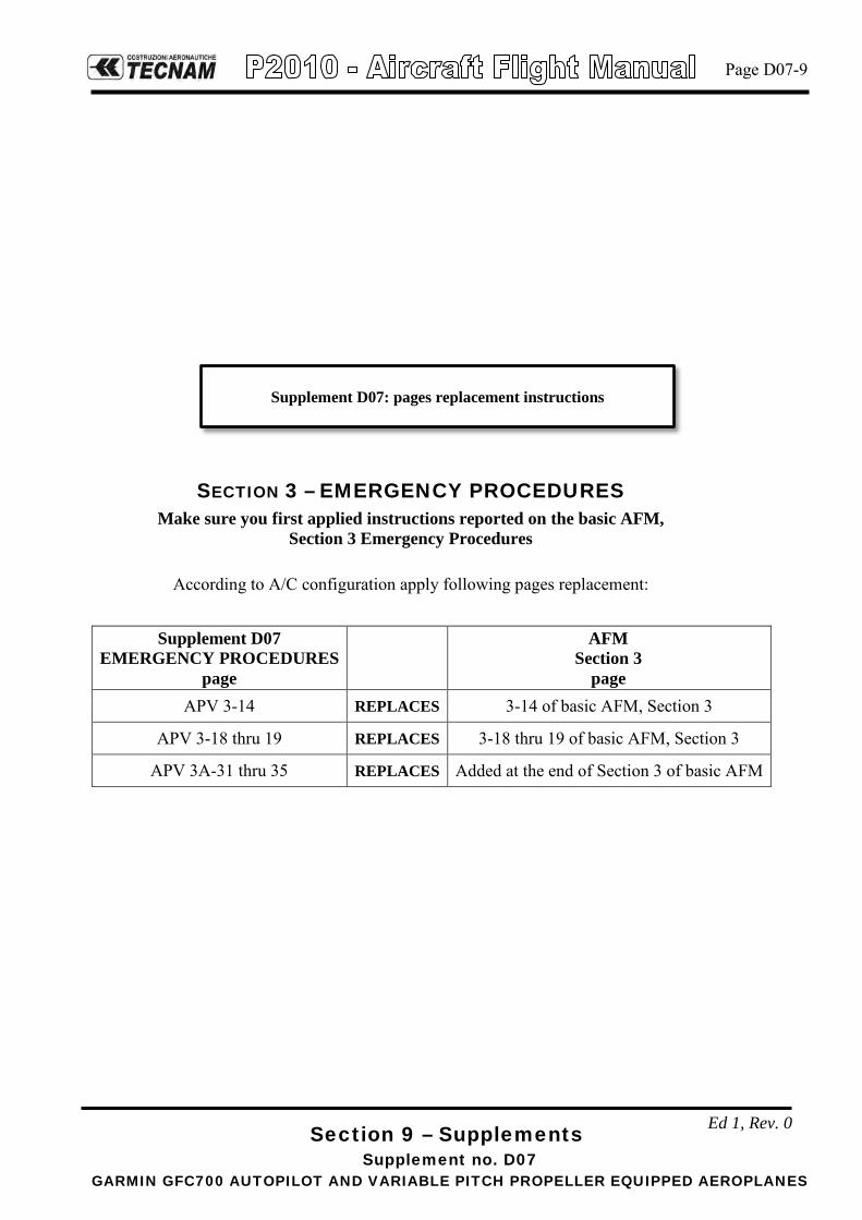
Page D07-9
Ed 1, Rev. 0
Section 9 – Supplements- Supplement no. D07
GARMIN GFC700 AUTOPILOT AND VARIABLE PITCH PROPELLER EQUIPPED AEROPLANES
SECTION 3 – EMERGENCY PROCEDURES Make sure you first applied instructions reported on the basic AFM,
Section 3 Emergency Procedures
According to A/C configuration apply following pages replacement:
Supplement D07 EMERGENCY PROCEDURES
page
AFM Section 3
page APV 3-14 REPLACES 3-14 of basic AFM, Section 3
APV 3-18 thru 19 REPLACES 3-18 thru 19 of basic AFM, Section 3
APV 3A-31 thru 35 REPLACES Added at the end of Section 3 of basic AFM
Supplement D07: pages replacement instructions

Page D07-10
Ed 1, Rev. 0
Section 9 – Supplements- Supplement no. D07
GARMIN GFC700 AUTOPILOT AND VARIABLE PITCH PROPELLER EQUIPPED AEROPLANES
INTENTIONALLY LEFT BLANK
Section 3 – Emergency procedures
POWERPLANT EMERGENCIES
6.3. PROPELLER OVERSPEED
In case of propeller overspeed in flight, apply following procedure:
1. Throttle Lever ……………. REDUCE power 2. Propeller Lever ……………. Decrease RPM 3. Mixture Lever ……………. As required 4. RPM indicator .…………… CHECK
If it is not possible to decrease propeller rpm, land as soon as possible applying Forced landing procedure. (See Para 11)
CAUTION
Maximum propeller rpm exceedance may cause engine components damage. Monitor engine RPM; overspeed shall be prevented by retarding propeller lever.
6.4. IRREGULAR RPM
1. Fuel pump: …………………………………ON 2. Fuel quantity and pressure indicators: …..…CHECK 3. If necessary: ……………………………….. SWITCH TANK
If engine continues to run irregularly
Land as soon as possible.
1st Edition, Rev. 0
AFMS N°D07 FOR GARMIN GFC700 AUTOPILOT AND VARIABLE PITCH PROPELLER EQUIPPEDAEROPLANES
Page APV 3-14

Section 3 – Emergency procedures
POWERPLANT EMERGENCIES
6.10. DEFECTIVE ENGINE CONTROLS
Defective Mixture Control Cable
1. Maintain altitude to the nearest arfield 2. During descent, check engine behaviour to a higher power setting. A lean
mixture can lead to engine roughness and loss of power. Landing approach must be planned accordingly.
WARNING
Go-around may then be impossible.
Defective Throttle Control Cable If power is sufficient to continue flight:
1. Approach nearest airfield, control engine power with Propeller lever 2. Perform landing with shut-down engine applying Forced landing proce-
dure. (See Para 11) If power is not sufficient to continue flight:
1. Carry out Forced landing procedure. (See Para 11)
Defective Propeller Lever Control Cable If power is sufficient to continue flight:
1. Approach nearest airfield, control engine power with throttle 2. Perform normal landing.
WARNING
Go-around may then be impossible.
If power is not sufficient to continue flight: 1. Carry out Forced landing procedure. (See Para 11)
1st Edition, Rev.0
AFMS N°D07 FOR GARMIN GFC700 AUTOPILOT AND VARIABLE PITCH PROPELLER EQUIPPEDAEROPLANES
Page APV 3-18

Section 3 – Emergency procedures
POWERPLANT EMERGENCIES
7. INFLIGHT ENGINE RESTART
7.1. PROPELLER WINDMILLING
WARNING
In case of engine shutdown, propeller will keep windmilling and will not stop, preventing the use of ignition key. Engine inflight restart must be performed without using ignition key with propeller wind-milling in order to avoid possible engine damages. Typical indication of a potential engine shutdown, with windmilling propeller, will be RPM running sub-idle below 600-500 RPM, to be confirmed by other engine instrument (OIL Pressure, CHT, EGT running down abnormally). Inflight engine restart may be performed during 1g flight anywhere within the normal operating envelope of the airplane.
1. Master switch ……………………………… Check ON 2. Fuel pump …………………………………. ON 3. Fuel quantity indicator …………………….. CHECK 4. Fuel Selector ………………………………. SWITCH TANK 5. Throttle Lever …………………………….. Minimum 1cm. above IDLE 6. Propeller Lever…………………………….. Full forward 7. Mixture …………………………………… FULL rich 8. Throttle lever ……………………………… SET as required
In case of unsuccessful engine restart:
Land as soon as possible applying Forced landing procedure. (See Para 11 Erro-
re. L'origine riferimento non è stata trovata.)
In case of successful engine restart:
Land as soon as possible
CAUTION
After engine restart, if practical, moderate propeller rpm to al-low the temperatures for stabilizing in the green arcs.
1st Edition, Rev.0
AFMS N°D07 FOR GARMIN GFC700 AUTOPILOT AND VARIABLE PITCH PROPELLER EQUIPPEDAEROPLANES
Page APV 3-19
Section 3 – Emergency procedures AUTOPILOT EMERGENCY PROCEDURES
AUTOPILOT EMERGENCY PROCEDURES 12
In the event of autopilot malfunction, or when the system is not per-forming as expected or commanded, take immediately the aircraft control disconnecting the autopilot which must be set inoperative until the failure has been identified and corrected.
12.1 AUTOPILOT HARDOVER OR FAILURE TO HOLD THE SELECTED
HEADING In case of A/P hardover or failure to hold selected heading, apply following pro-cedure:
Accomplish items 1 and 2 simultaneously:
1. Airplane control wheel GRASP FIRMLY and OVERPOWER if necessary to regain aircraft control
2. AP DISC/TRIM INTR switch PRESS
3. AP MASTER SWITCH OFF
4. AP Circuit Breaker PULL
WARNING
Following an A/P or MET system malfunction, do not engage the autopilot until the cause of the malfunction has been cor-rected.
When Autopilot is disconnected, it may be necessary operate the pitch trim through either the Manual Electric Trim Switch or the Trim Wheel.
NOTE
NOTE
1st Edition, Rev. 0
AFMS N°D07 FOR GARMIN GFC700 AUTOPILOT AND VARIABLE PITCH PROPELLER EQUIPPEDAEROPLANES
Page APV 3-31

Section 3 – Emergency procedures AUTOPILOT EMERGENCY PROCEDURES
12.2 ALTITUDE LOST DURING A PITCH AXIS AUTOPILOT MALFUNC-
TION AND RECOVERY Following table addresses the altitude lost during a pitch axis malfunction and re-covery for each reported flight phase:
Flight phase Altitude loss
Climb 90 ft
Cruise 200 ft
Descent 170 ft
Maneuvering 210 ft
Approach 70 ft
12.3 ELECTRIC TRIM MALFUNCTION In case of Electric Trim malfunction (either in AP Autotrim mode or when manu-ally operated through the Manual Electric Trim Switch), apply following proce-dure:
1. AP DISC/TRIM INTR switch PRESS and HOLD
2. TRIM MASTER SWITCH OFF
3. TRIM Circuit Breaker PULL
4. AP DISC/TRIM INTR switch RELEASE
CAUTION
When Autopilot is disconnected because of a pitch trim malfunction, hold the control wheel firmly.
When electric trim is disconnected, it is necessary operate the pitch
trim through the Trim Wheel.
When electric trim is disconnected, Autopilot system can be operated
both in pitch and roll modes; nevertheless, when a pitch mode (ALT HOLD, VS, GS) is engaged, the Autopilot will provide an annuncia-tion whenever it is necessary to manually trim the aircraft about the pitch axis using the Trim Wheel. Make reference to “Garmin G1000 Integrated Avionic System Pilot’s Guide”for Tecnam P2010 (Part No. 190-01830-00 Revision A dated September 25, 2014 or a more updat-ed version).
NOTE
NOTE
1st Edition, Rev. 0
AFMS N°D07 FOR GARMIN GFC700 AUTOPILOT AND VARIABLE PITCH PROPELLER EQUIPPEDAEROPLANES
Page APV 3-32
Section 3 – Emergency procedures AUTOPILOT EMERGENCY PROCEDURES
12.4 AMPLIFIED EMERGENCY PROCEDURES The following observations provide additional information for more complete un-derstanding of the recommended course(s) of action in emergency situations.
1. An autopilot or autotrim malfunction occurs when there is an un-commanded deviation in the airplane flight path or when there is abnormal control wheel or trim wheel motion. In some cases, (es-pecially for autopilot trim), there may be little to no airplane mo-tion, but the PITCH TRIM annunciator (LH side of PDF) may come on.
2. The primary concern in reacting to an autopilot or autopilot trim
system malfunction, or to an automatic disconnect of the autopilot, is to keep control of the airplane. Immediately grasp the control wheel and push and hold the A/P DISC/TRIM INT switch throughout the recovery. Manipulate the controls as required to safely keep the airplane within all of its operating limitations. Ele-vator trim should be used manually as needed to relieve control forces. Switch the AP MASTER SWITCH to OFF and, when time is available after aircraft recovery, open (pull) the AUTOPILOT cir-cuit breaker on the lower right hand corner of the circuit breaker panel to completely disable the autopilot system.
3. A MET (Manual Electric Trim) system malfunction (without pilot
actuation of the manual electric trim switches) may be recognized by the PITCH TRIM annunciator coming on or by unusual trim wheel motions with the autopilot not engaged. As with an autopilot malfunction, the first concern following a manual electric trim sys-tem malfunction is to keep the airplane in control. Grasp the con-trol wheel firmly and push and hold down the A/P DISC/TRIM INT switch. Switch the trim cut-out switch to OFF.
1st Edition, Rev. 0
AFMS N°D07 FOR GARMIN GFC700 AUTOPILOT AND VARIABLE PITCH PROPELLER EQUIPPEDAEROPLANES
Page APV 3-33

Section 3 – Emergency procedures AUTOPILOT EMERGENCY PROCEDURES
12.5 ABNORMAL PROCEDURES This table is a quick access table that provide additional information regarding re-sidual A/P capabilities in case loss of autopilot servos and/or pitch trim servo.
With A/P engaged, in case of loss of both A/P servos and pitch trim servo, the disconnect tone will play continuously, until acknowledged through A/P button on MFD or trim switch on control wheel.
LO
SS O
F A
/P
SER
VO
L
OSS
OF
PIT
CH
TR
IM
SER
VO
A
/P S
TA
TU
S N
OT
ES
A/P
FU
NC
TIO
NA
LIT
Y
ESP
ST
AT
US
USP
ST
AT
US
ON
O
FF
ON
O
FF
X
DIS
ENG
AG
ED
MEP
T U
nava
ilabl
e PT
RM
red
on P
FD
NO
VER
T M
OD
ES o
n PF
D
PTR
M C
&M
red
cros
s on
MFD
SY
S pa
ge
A/P
can
be
enga
ged,
but
on
ly la
tera
l mod
es w
ill b
e co
rrect
ly fl
own
(lack
of
pitc
h tri
m).
FD
is o
pera
tive
in a
ll m
odes
X
X
(can
’t ho
ld 6
5 kt
s w
ithou
t pitc
h tri
m
avai
labl
e)
X
A/P
disc
onne
ct
PTC
H re
d an
nunc
iatio
n on
PFD
N
O V
ERT
MO
DES
on
PFD
ES
P Fa
il on
ale
rt w
indo
w
PTC
H C
&M
red
cros
s on
MFD
SY
S pa
ge
RO
LL C
&M
red
cros
s on
MFD
SY
S pa
ge
A/P
can
’t be
eng
aged
FD
is o
pera
tive
in a
ll m
odes
X
X
(o
nly
MIN
SPD
w
arni
ng)
X
X
A/P
disc
onne
ct &
MEP
T U
nava
ilabl
e
AFC
S re
d an
nunc
iatio
n on
PFD
(1”)
ES
P Fa
il on
ale
rt w
indo
w
PTC
H C
&M
red
cros
s on
MFD
SY
S pa
ge
RO
LL C
&M
red
cros
s on
MFD
SY
S pa
ge
PTR
M C
&M
red
cros
s on
MFD
SY
S pa
ge
A/P
can
’t be
eng
aged
FD
is o
pera
tive
in a
ll m
odes
X
X
(o
nly
MIN
SPD
w
arni
ng)
X
ENG
AG
ED
MEP
T U
nava
ilabl
e PT
RM
red
annu
ncia
tion
on P
FD
NO
VER
T M
OD
ES o
n PF
D
PTR
M C
&M
red
cros
s on
MFD
SY
S pa
ge
A/P
fully
ope
rativ
e FD
is o
pera
tive
in a
ll m
odes
X
X
(can
’t ho
ld 6
5 kt
s w
ithou
t pitc
h tri
m
avai
labl
e)
X
A/P
disc
onne
ct
PTC
H re
d an
nunc
iatio
n on
PFD
N
O V
ERT
MO
DES
on
PFD
ES
P Fa
il on
win
dow
ale
rt PT
CH
C&
M re
d cr
oss o
n M
FD S
YS
page
R
OLL
C&
M re
d cr
oss o
n M
FD S
YS
page
A/P
disc
onne
cts a
nd c
an’t
be e
ngag
ed
FD is
ope
rativ
e in
all
mod
es
X
X
(onl
y M
INSP
D
war
ning
)
X
X
A/P
con
tinuo
us d
isco
nnec
t ton
e ca
n be
si
lenc
ed th
roug
h th
e A
P bu
tton
on M
FD
an
d by
the
trim
switc
h on
con
trol
whe
el.
A/P
disc
onne
ct &
MEP
T U
nava
ilabl
e
AFC
S re
d an
nunc
iatio
n on
PFD
(1”)
N
O V
ERT
MO
DES
on
PFD
ES
P Fa
il on
ale
rt w
indo
w
PTC
H C
&M
red
cros
s on
MFD
SY
S pa
ge
RO
LL C
&M
red
cros
s on
MFD
SY
S pa
ge
PTR
M C
&M
red
cros
s on
MFD
SY
S pa
ge
A/P
disc
onne
cts a
nd c
an’t
be e
ngag
ed
FD is
ope
rativ
e in
all
mod
es
X
X
(onl
y M
INSP
D
war
ning
)
NOTE
1st Edition, Rev. 0
AFMS N°D07 FOR GARMIN GFC700 AUTOPILOT AND VARIABLE PITCH PROPELLER EQUIPPEDAEROPLANES
Page APV 3-34

Section 3 – Emergency procedures AUTOPILOT EMERGENCY PROCEDURES
This table is a quick access table that provide additional information regarding re-sidual A/P capabilities in case of loss of PFD or MFD.
PFD MFD NOTES
ON → OFF ON A/P reverts to PIT & ROLL (from any mode selected) No aurals from A/P (both A/P DISC & USP)
ON ON → OFF
A/P stays in the selected mode A/P control keyboard unavailable A/P can be disconnected with A/P DISC button on control wheel FD command bars cannot be eliminated ESP Off on alert window on PFD
ON → OFF ON → OFF A/P automatically disconnects after ~ 4 to 5 seconds A/P disconnection tone plays endlessly until A/P DISC button is pressed
1st Edition, Rev. 0
AFMS N°D07 FOR GARMIN GFC700 AUTOPILOT AND VARIABLE PITCH PROPELLER EQUIPPEDAEROPLANES
Page APV 3-35

Page D07-11
Section 9 – Supplements - Supplement no. D07
GARMIN GFC700 AUTOPILOT AND VARIABLE PITCH PROPELLER EQUIPPED AEROPLANES
Ed. 1, Rev.0
SECTION 4 – NORMAL PROCEDURES Make sure you first applied instructions reported on the basic AFM,
Section 4 Normal Procedures
According to A/C configuration apply following pages replacement:
Supplement D07 NORMAL PROCEDURES
page
AFM Section 4
page APV 4-7 REPLACES 4-7 of basic AFM, Section 4
APV 4-15 REPLACES 4-15 of basic AFM, Section 4
APV 4-19 thru 26 REPLACES 4-19 thru 26 of basic AFM, Section 4
APV 4-27 thru 38 REPLACES Added at the end of Section 4 of basic AFM
Supplement D07: pages replacement instructions

Page D07-12
Section 9 – Supplements - Supplement no. D07
GARMIN GFC700 AUTOPILOT AND VARIABLE PITCH PROPELLER EQUIPPED AEROPLANES
Ed. 1, Rev.0
INTENTIONALLY LEFT BLANK

Section 4 – Normal procedures
AIRSPEED FOR NORMAL OPERATIONS
3. AIRSPEEDS FOR NORMAL OPERATIONS
The following airspeeds are those which are significant for normal operations.
FLAPS 1160kg (2557lbs)
Rotation Speed (VR) T/O 60 KIAS
Best Angle-of-Climb Speed (VX) 0° 75 KIAS
Best Rate-of-Climb speed (VY) 0° 82 KIAS
Flaps (VFE) T/O & LAND 91 KIAS
No flaps approach 0° 80 KIAS
Approach speed T/O 75 KIAS
Final Approach Speed FULL 70 KIAS
Manoeuvring speed (VA) 0° 120 KIAS
Vglide 0° 84 KIAS
Never Exceed Speed (VNE) 0° 166 KIAS
AFMS N°D07 FOR GARMIN GFC700 AUTOPILOT AND VARIABLE PITCH PROPELLER EQUIPPEDAEROPLANES
Page APV 4-7
1st Edition, Rev. 0

Section 4 – Normal procedures
CHECKLISTS
5. CHECKLISTS
5.1. BEFORE STARTING ENGINE (AFTER PREFLIGHT INSPECTION)
1. Seat position and safety belts: adjust 2. Flight controls: operate full stroke checking for movement smoothness, free of
play and friction. 3. Parking brake: engage 4. Throttle friction: adjust 5. Throttle: IDLE 6. Propeller Lever: HIGH RPM 7. Mixture control Lever: LEAN 8. Circuit Breakers: check all IN 9. Master switch: ON, wait PFD turn on, Check ALT OUT caution ON, Check LOW
FP and LOW OP warning ON 10. Only before the first flight of the day:
Standby Instrument: Check no red crosses displayed. a. Press and hold the control knob (approx. 2 sec) b. Rotate the knob selecting “INFO>” page then press it c. Select “BATTERY INFO” page then press the knob d. Check “CHARGE (%)” to be more than 80%, then exit menu
11. Avionic Master switch: ON, wait MFD turn on, check instruments, check Voltage on Main and Essential Buses.
12. Fuel quantity: compare the fuel quantity indicators information with fuel quantity visually checked into the tanks (see Pre-flight inspection – External inspection), then update the Garmin fuel content in the totalizer accordingly
The totalizer function available on Garmin Engine page allows input only up to 230lts (maximum usable fuel). Initial Fuel indication on totalizer must be correct-ed manually (as it does not use the aircraft fuel quantity indicators as input). Once correctly initialized, fuel consumption on totalizer is very precise as it take instantaneous fuel flow for computation.
13. Electric fuel pump: ON (check for audible pump noise and increase of fuel pressure) 14. Warning “LOW FUEL PRESSURE”: extinguished 15. Electric fuel pump: OFF 16. Flap control: cycle fully extended and then set to T/O 17. Pitch Trim: cycle fully up and down, then set to NEUTRAL 18. Rudder trim: cycle full right and left, then set to NEUTRAL
WARNING
Pitch trim position other than in neutral position would affect take off performance and take off rotation execution at the correct VR.
19. Nav & Strobe lights: ON
In absence of RH seat occupant: fasten seat belts around the seat in order to prevent any interference with the aeroplane flight control operation and with rapid egress in an emergency.
20. Doors: Closed and locked
NOTE
NOTE
1st Edition, Rev. 0
AFMS N°D07 FOR GARMIN GFC700 AUTOPILOT AND VARIABLE PITCH PROPELLER EQUIPPEDAEROPLANES
Page APV 4-15

Section 4 – Normal procedures
CHECKLISTS
5.5. BEFORE TAKEOFF
1. Parking brake: brake pedal press, ON 2. Engine instruments: Check within limits 3. ALT OUT caution: OFF (check) 4. Electric Fuel pump: ON 5. Fuel selector valve: select the fullest tank 6. Fuel pressure: check 7. Mixture: FULL RICH
For 5000ft density altitude and above, or high ambient temperatures, a FULL RICH mixture may cause rough running of the engine or a loss of performance. The mixture may be adjusted to obtain smooth engine operations.
8. Throttle: set 1500 RPM a. Alternate Air check: Alternate Air: PULL (Check drop 50-100 RPM) b. Mixture check: Mixture: reduce EGT: check increase FF: check decrease Mixture: FULL RICH
9. Throttle: 2100 RPM 10. Propeller Lever:
Pull back until a drop of max. 500 RPM is reached then high RPM
Cycle 3 times
11. Magneto Check: L – BOTH – R – BOTH Max RPM drop: 175 RPM Max. difference: 50 RPM
12. Throttle: Idle 13. Flaps: check T/O 14. Pitch and Rudder trim: check neutral 15. Flight controls: check free 16. Seat belts: check fastened 17. Doors: check closed and locked 18. Parking brake: Release 19. Landing light: ON as required 20. XPDR: ON
NOTE
1st Edition, Rev. 0
AFMS N°D07 FOR GARMIN GFC700 AUTOPILOT AND VARIABLE PITCH PROPELLER EQUIPPEDAEROPLANES
Page APV 4-19

Section 4 – Normal procedures
CHECKLISTS
5.6. TAKEOFF
For 5000ft density altitude and above, or high ambient temperatures, a FULL RICH mixture may cause rough running of the engine or a loss of performance. The mixture may be ad-justed to obtain smooth engine operations. Lean to maximum RPM at Full Throttle prior to take-off where airports are at 5000ft density altitude or higher. During climb, a rough method of correctly leaning is to slowly reduce mixture lever until an increase of appr.ly 50-100 RPM is noticed at constant IAS or EGT reaches 1375°F mark.
1. Pitot HEAT: ON if required 2. Fuel pump: ON 3. Brakes: apply
4. Throttle: FULL and check approximately 2680 20 RPM
WARNING
Engine proper performance at full throttle shall be checked early in the ground roll in order to abandon take-off if necessary. A rough engine, sluggish RPM increase or failure to reach take-off RPM are reasons for abandoning the take-off. If the engine oil is cold, an oil pressure in the yellow sec-tor is permissible.
5. Engine instruments: check parameters within the limits 6. Brakes: Release 7. Rotation speed VR: 60 KIAS 8. Airspeed: 67 KIAS
Above a safe height: 9. Propeller lever: 2600 RPM 10. Landing lights: OFF
NOTE
1st Edition, Rev. 0
AFMS N°D07 FOR GARMIN GFC700 AUTOPILOT AND VARIABLE PITCH PROPELLER EQUIPPEDAEROPLANES
Page APV 4-20

Section 4 – Normal procedures
CHECKLISTS
5.7. CLIMB
Due to position of fuel sensors, during climb fuel gauges in cockpit will indicate a fuel quantity slightly lower than the real amount. Regaining level flight will immediately restore correct indications.
For 5000ft density altitude and above, or high ambient temperatures, a FULL RICH mixture may cause rough running of the engine or a loss of performance. The mixture may be adjusted to obtain smooth engine operations. Lean to maximum RPM at Full Throttle prior to take-off where airports are at 5000ft density altitude or higher. During climb, a rough method of correctly leaning is to slowly reduce mixture lever un-til an increase of appr.ly 50-100 RPM is noticed at constant IAS or EGT reaches 1375°F mark.
1. Flaps: UP (minimum speed 73 KIAS)
Expect to adjust pitch trim (pitch up) when retracting flaps after take-off
2. Establish climb Vy: 82 KIAS 3. Electrical fuel pump: OFF 4. Fuel pressure: check within limits 5. Throttle: FULL 6. MIXTURE: RICH, above 5000ft keep EGT constant 7. Engine instruments: in the GREEN
If the fuel pressure warning light illuminates, or the fuel pressure indication is below green arc, the electrical fuel pump must be switched ON.
NOTE
NOTE
NOTE
NOTE
1st Edition, Rev. 0
AFMS N°D07 FOR GARMIN GFC700 AUTOPILOT AND VARIABLE PITCH PROPELLER EQUIPPEDAEROPLANES
Page APV 4-21

Section 4 – Normal procedures
CHECKLISTS
5.8. CRUISE
1. Power: set performance as required, refer to table in section 5 of AFM 2. Propeller lever: 1800-2400 RPM 3. Fuel tank selector: as required to maintain symmetric balance 4. Mixture: set in accordance with following para 5.9
To optimize engine life, the cylinder head temperature (CHT) should lie between 150°F and 400°F in continuous operation, and not rise above 435°F in fast cruise.
Monitor and manually compensate asymmetrical fuel consumption by switching fuel selector valve. Switch ON the electric fuel pump prior to swap the fuel feeding from one tank to another.
5.9. MIXTURE ADJUSTMENT RECOMMENDATION
CAUTION
The maximum permissible cylinder head temperature (500 °F) must never be ex-ceeded. The mixture control lever should always be moved slowly. Before selecting a higher power setting the mixture control lever should, on each occasion, be moved slowly to fully RICH before throttle adjustment. Care should always be taken that the cylinders do not cool down too quickly. The cooling rate should not exceed 50 °F per minute.
For maximum service life cylinder head temperature should be kept below 475 °F (high performance cruise) and below 435 °F (for economy cruise).
Best Cruise Economy Mixture The best economy mixture setting may only be used up to a power setting of 75 %. In order to obtain the lowest specific fuel consumption at a particular power setting, proceed as follows:
- Slowly pull the mixture control lever back towards LEAN until the engine starts to run rough-ly.
- Then push the mixture control lever forward just far enough to restore smooth running. At the same time the exhaust gas temperature (EGT) should reach a maximum.
Best Cruise Power Mixture The mixture can be set for maximum performance at all power settings:
- The mixture should first be set as for best economy. - The mixture should then be enriched until the exhaust gas temperature is approximately
100°F lower. This mixture setting produces the maximum performance for a given manifold pressure and is mainly used for high power settings (approximately 75 %).
NOTE
NOTE
NOTE
AFMS N°D07 FOR GARMIN GFC700 AUTOPILOT AND VARIABLE PITCH PROPELLER EQUIPPEDAEROPLANES
Page APV 4-22
1st Edition, Rev. 0

Section 4 – Normal procedures
CHECKLISTS
5.10. DESCENT
Due to position of fuel sensors, during descent fuel gauges in cockpit will indicate a fuel quantity slightly higher than the real amount. Regaining level flight will immediately re-store correct indications.
1. Mixture control: slowly full rich 2. Propeller lever: as required 3. Throttle: reduce as required
Shock cooling shortens engine life. When reducing power, the change in cylinder head temperature should not exceed 50°F per minute. In order to ensure best practice and avoid potential illumination of ALT FAIL (due to low propeller speed), the following best practice should be observed: - Reducing power to maintain a minimum descent speed of 84 KIAS (best glide) and / or
a blade angle to maintain 850 RPM; - Opening the ALTER AIR command to full open (to avoid ice accretion).
CAUTION
The maximum permissible cylinder head temperature (500 °F) must never be exceeded. The mixture control lever should always be moved slowly. Before selecting a higher power setting the mixture control lever should, on each occasion, be moved slowly to fully RICH. Care should always be taken that the cylinders do not cool down too quickly. The cooling rate should not exceed 50 °F per minute.
NOTE
NOTE
1st Edition, Rev. 0
AFMS N°D07 FOR GARMIN GFC700 AUTOPILOT AND VARIABLE PITCH PROPELLER EQUIPPEDAEROPLANES
Page APV 4-23
Section 4 – Normal procedures
CHECKLISTS
5.11. BEFORE LANDING
1. Electric fuel pump: ON 2. Fuel valve: select the fullest tank 3. Landing Light: ON On downwind, leg abeam touch down point: 4. Flaps: set T/O (below 90KIAS)
Expect to adjust pitch trim (pitch down) when extending flaps to T/O or LAND
5. Approach speed: set On final leg, before landing: 6. Mixture control lever: RICH 7. Propeller Lever: HIGH RPM 8. Flaps: LAND 9. Final Approach Speed: set 10. Optimal touchdown speed: 60 KIAS
CAUTION
In conditions such as (e.g.) strong wind, danger of windshear or turbulence a higher approach speed shall be selected..
5.12. BALKED LANDING/MISSED APPROACH
1. Throttle: FULL 2. Speed: keep over 80 KIAS, climb to VY or VX as applicable 3. Flaps position: T/O Above a safe height: 4. Propeller lever: 2600 RPM 5. Landing lights: OFF
5.13. GO-AROUND
1. Throttle: FULL 2. Speed: keep over 80 KIAS, climb to VY or VX as applicable 3. Flaps position: T/O
5.14. AFTER LANDING
1. Throttle: Idle 2. Brakes: apply 3. Pitot heat: OFF (if ON) 4. Flaps: UP 5. Electric Fuel Pump: OFF 6. XPDR: OFF 7. Landing light: OFF
NOTE
AFMS N°D07 FOR GARMIN GFC700 AUTOPILOT AND VARIABLE PITCH PROPELLER EQUIPPEDAEROPLANES
Page APV 4-24
1st Edition, Rev. 0

Section 4 – Normal procedures
CHECKLISTS
5.15. ENGINE SHUT DOWN
1. Parking brake: set 2. Keep engine running at 1200 propeller rpm for about one minute in order to
reduce latent heat. 3. Avionic equipment: OFF 4. Throttle: idle 5. Magnetos: Check OFF – BOTH 6. Mixture: closed 7. Ignition key: OFF, key extracted 8. Strobe light: OFF 9. Avionic Master: OFF 10. Master & Generator switches: OFF 11. Fuel selector valve: OFF
WARNING
For safety, verify propeller is fully stopped before any other action.
CAUTION
Instruct passenger to fully open RH door and depart, avoiding contact with wheels and sharp wing control surfaces edges.
5.16. POSTFLIGHT CHECKS
1. Flight controls: lock by means of seat belts 2. Wheel chocks and wing mooring lines: Set 3. Parking brake: Release 4. Doors: Close and lock 5. Protection plugs: set over pitot tube, stall warning, static ports
AFMS N°D07 FOR GARMIN GFC700 AUTOPILOT AND VARIABLE PITCH PROPELLER EQUIPPEDAEROPLANES
Page APV 4-25
1st Edition, Rev. 0

Section 4 – Normal procedures
CHECKLISTS
5.17. FLIGHT IN RAIN
Performance deteriorates in rain; this applies particularly to take-off distance and maximum Horizontal speed. The effect on flight characteristics is minimal.
5.18. REFUELLING
Before refuelling, the airplane must be connected to electrical ground.
5.19. FLIGHT AT HIGH ALTITUDE
At high altitudes the provision of oxygen for the occupant is necessary. Legal requirements for the provision of oxygen should be adhered to (see para 2.9).
AFMS N°D07 FOR GARMIN GFC700 AUTOPILOT AND VARIABLE PITCH PROPELLER EQUIPPEDAEROPLANES
Page APV 4-26
1st Edition, Rev. 0

Section 4 – Normal procedures AUTOPILOT NORMAL PROCEDURES
AUTOPILOT NORMAL PROCEDURES 6
For detailed description of A/P selections, behaviour and display out-look, refer to the “Garmin G1000 Pilot’s Guide for the Tecnam P2010” (Part No. 190-01830-00 Revision A dated September 25, 2014 or a more updated version); it must be always carried in the aircraft and made available to the pilot at all time.
If A/P Master switch and /or Trim disconnect switch are inadvertently switched OFF, it will be necessary to reset both switches to allow A/P and pitch trim functionality. In this case pilot will make sure A/P is dis-engaged before reset. The single reset of only one of the switches will not permit to reset the single functionality.
PREFLIGHT: AIRCRAFT PRE-FLIGHT CHECKS:
1) MASTER SWITCH (BAT): ON. 2) AVIONICS MASTER SWITCH: ON. 3) AUTOPILOT MASTER SWITCH: ON. 4) POWER APPLICATION and SELFCTEST - The autopilot tests itself when
power is first made available. The test is a sequence of internal checks before starting normal system operation. The test sequence is shown on PFD left upper corner by the red AFCS label followed by the white PFT label, ending with double AP disengagement tone (which indicates a successful completion). Autopilot system availability is shown under system page on MFD.
WARNING
If the red AFCS stays ON, the A/P has failed the preflight test. Put the A/P MASTER SWITCH OFF to make sure that the A/P will not operate.
5) MANUAL ELECTRIC TRIM (MET) SYSTEM - TEST.
Pitch Trim: cycle fully up and down, then set to NEUTRAL.
Both pitch trim halves must be actuated to move pitch trim. Any movement of the elevator trim wheel during the check of either the LH or RH Switch only means that the Manual Electric Trim System has failed.
6) ELEVATOR TRIM WHEEL - SET pointer to takeoff position. 7) AVIONICS MASTER SWITCH: OFF 8) MASTER SWITCH (BAT): OFF
NOTE
NOTE
NOTE
1st Edition, Rev.0
AFMS N°D07 FOR GARMIN GFC700 AUTOPILOT AND VARIABLE PITCH PROPELLER EQUIPPEDAEROPLANES
Page APV 4-27

Section 4 – Normal procedures AUTOPILOT MODES
AUTOPILOT MODES 7
WARNING
When the A/P is engaged, the pilot must continuously monitor and be ready to disengage the A/P. Do the Emergency Recovery procedure if A/P operation is erratic or does not correctly control the airplane.
The “Garmin G1000 Pilot’s Guide for the Tecnam P2010” (Part No. 190-01830-00 Revision A dated September 25, 2014 or a more updated version) must be carried in the aircraft and made available to the pilot at all time.
Autopilot tracking performance will not be as good as usual in turbu-
lence.
Autopilot engagement / disengagement is not equivalent to servo en-gagement/disengagement. Use the CWS Button to disengage the pitch and roll while the autopilot remains active.
HDG
Pressing the HDG knob synchronizes the Selected Heading to the cur-rent heading. In this case expect a small heading overshoot that will be subsequently corrected.
VS MODE
WARNING
Selection of a vertical speed beyond the capability of the aircraft can create a condition of reduced airspeed, and possibly lead to USP acti-vation. During A/P operation, pilot must set the A/P Vs rate and engine power to make sure that airspeed remains within autopilot envelope and does not exceed any other airplane operating limitation.
WARNING
VS is an open mode, which will engage irrespective of Selected Alti-tude. Pilot monitoring is always required to make sure that a correct Selected Altitude is shown on PFD.
SELECTED ALTITUDE CAPTURE MODE (ALTS)
Pressing the CWS Button while in Selected Altitude Capture Mode does not cancel the mode.
NOTE
NOTE
NOTE
NOTE
NOTE
1st Edition, Rev.0
AFMS N°D07 FOR GARMIN GFC700 AUTOPILOT AND VARIABLE PITCH PROPELLER EQUIPPEDAEROPLANES
Page APV 4-28

Section 4 – Normal procedures AUTOPILOT MODES
ALTITUDE HOLD MODE (ALT)
Turning the ALT knob while in Altitude Hold Mode changes the Selected Altitude, but not the FD Altitude Refrence, and does not cancel the mode.
FLC MODE
CAUTION
The Selected Altitude MUST be set before selecting Flight Level Change Mode.FLC IAS selection is directly linked to actual IAS, pi-lot will need to monitor airspeed after selection of FLC mode.
VERTICAL NAVIGATION MODES (VPTH, ALTV)
VNV is disabled when parallel or dead reckoning mode is active.
The selected altitude takes precedence over any other vertical con-straints.
If another pitch mode key is pressed while Vertical Path Tracking Mode
is selected, VPTH mode reverts to armed. If the selected altitude is not at least 75 ft below the VNV Target Alti-
tude, the FD captures the Selected Altitude once Vertical Path Tracking Mode become active (ALTS is armed rather than ALTV).
Altitude preselect must show an altitude below the flight plan’s Target Altitude. If the selected altitude is not at least 75 ft below the VNV Target Alti-tude, the FD captures the Selected Altitude once Vertical Path Tracking Mode become active (ALTS is armed rather than ALTV).
If VPTH is armed more than 5 minutes prior to descent path capture, acknowledgement is required for the FD to transition from Altitude Hold to VPTH. To proceed with descent path capture if the white “VPTH” flashes,do the following:
- Press VNV Kay - Turn ALT knob to adjust the Selected Altitude.
If the selected altitude is not at least 75 ft below the VNV Target Alti-tude, the FD captures the Selected Altitude once Vertical Path Tracking Mode become active (ALTS is armed rather than ALTV).
Armed VNV Target Altitude and Selected Altitude capture modes are
mutually exclusive. Selected Altitude Capture Mode is armed also (not annunciated) whenever VNV Target Altitude Capture Mode is armed.
APPROACH MODES
The selected navigation receiver must have a valid VOR or LOC signal or active GPS course for the flight director to enter Approach Mode.
NOTE
NOTE
NOTE
NOTE
NOTE
NOTE
NOTE
NOTE
1st Edition, Rev.0
AFMS N°D07 FOR GARMIN GFC700 AUTOPILOT AND VARIABLE PITCH PROPELLER EQUIPPEDAEROPLANES
Page APV 4-29

Section 4 – Normal procedures AUTOPILOT ABNORMAL PROCEDURES
AUTOPILOT ABNORMAL PROCEDURES 8Loss of a single GPS:
In case of loss of a single GPS, RNAV guidance will still be available as the sys-tem will automatically revert to the other available GPS without losing any auto-pilot / FD guidance. The ALERT window will switch to ADVSY and start to flash; when selected a “AHRS1 GPS – AHRS1 using backup GPS source” CAS message will appear in-side the alert window.
Loss of both GPS:
In case of loss of both GPS, RNAV guidance will not be available anymore. The ALERT window will switch to ADVSY and start to flash; when selected a “GPS NAV LOST – Loss of GPS navigation. Insufficient satellites” CAS message will appear inside the alert window. In this case also ESP will be lost and the “ESP OFF” CAS message will also appear inside the alert window. Further to that, a yellow “LOI” (loss of integrity) CAS message will be displayed on the HIS and all other GPS related information (e.g. wind) will turn to yellow. If GPS nave mode is being selected, the HSI on the PFD will not display the devi-ation bar. If GPS is selected as navigation source a “AHRS1 GPS – AHRS1 oper-ating exclusively in no-GPS mode“ CAS message will appear inside the alert win-dow.
Dead Reckoning Mode only functions in Enroute (ENR) or Oceanic (OCN) phase of flight. In all other phases, an invalid GPS solution pro-duces a “NO GPS POSITION” annunciation on the map and the G1000 stops using GPS.
It is important to note that estimated navigation data supplied by the G1000 in DR Mode may become increasingly unreliable and must not be used as a sole means of navigation. If while in DR Mode airspeed and/or heading data is also lost or not available, the DR function may not be capable of accurately tracking estimated position and, consequently, the system may display a path that is different than the actual movement of the aircraft. Estimated position information displayed by the G1000 through DR while there is no heading and/or airspeed data available shall not be used for navigation. DR Mode is inherently less accurate than the standard GPS/SBAS Mode due to the lack of satellite measurements needed to determine a position.
NOTE
1st Edition, Rev.0
AFMS N°D07 FOR GARMIN GFC700 AUTOPILOT AND VARIABLE PITCH PROPELLER EQUIPPEDAEROPLANES
Page APV 4-30

Section 4 – Normal procedures AUTOPILOT ABNORMAL PROCEDURES
Changes in wind speed and/or wind direction compound the relative in-
accuracy of DR Mode. Because of this degraded accuracy, other naviga-tion equipment must be relied upon for position awareness until GPS-derived position data is restored.
DR Mode is indicated on the G1000 by the appearance of the letters ‘DR’ super-imposed in yellow over the ‘own aircraft’ symbol. In addition, ‘DR’ is prominently displayed in yellow on the HSI slightly above and to the right of the aircraft symbol on the CDI. Also, the CDI deviation bar is removed from the display. Lastly, but at the same time, a ‘GPS NAV LOST’ alert message appears on the PFD. Normal navigation using GPS/SBAS source data resumes automatically once a valid GPS solution is restored. As a result of operating in DR Mode, all GPS-derived data is computed based upon an estimated position and is displayed as yellow text on the display to denote degraded navigation source information. Also, while the G1000 is in DR Mode, some terrain functions are not available. Additionally, the accuracy of all nearest information (airports, airspaces, and waypoints) is questionable. Finally, airspace alerts continue to function, but with degraded accuracy.
RAIM AVAILABILITY: Because of tighter protection limit on approaches, there may be times when RAIM is not available. The G1000 automatically monitors RAIM and warns with an alert message when it is not available. If RAIM is not predicted to be available for the final approach course, the approach does not become active, as indicated by the message “Approach is not active”. If RAIM is not available when crossing the FAF, the missed approach procedure must be flown.
NOTE
1st Edition, Rev.0
AFMS N°D07 FOR GARMIN GFC700 AUTOPILOT AND VARIABLE PITCH PROPELLER EQUIPPEDAEROPLANES
Page APV 4-31
Section 4 – Normal procedures ADDITIONAL GUIDANCE FOR RNAV GPS
ADDITIONAL GUIDANCE FOR RNAV GPS 9Experience of RNAV systems, and Flight FMS in general, has identified the pit-falls of waypoint entry error at the receiver as well as inaccuracies and errors in the database itself. Research and experience have both shown that human error, often the result of a lack of familiarity with the airborne equipment, represents the major hazard in op-erations using RNAV systems. Therefore, it is imperative that pilots understand their system thoroughly and are able to determine whether it is safe to proceed. This requires robust procedures, which check for possible errors in the computer database, monitor continued performance of the RNAV systems and enable pilots to identify and avoid not only their own mistakes but also errors in the infor-mation presented to them. Flight planning on RNAV routes should include the following recommendation. - During the pre-flight planning phase, given a GPS constellation of 23 satellites or less (22 or less for GPS stand-alone equipment that incorporate pressure alti-tude aiding), the availability of GPS integrity (RAIM) should be confirmed for the intended flight (route and time). This should be obtained from a prediction pro-gram either ground-based, or provided as an equipment function, or from an alter-native method acceptable to the Authority; - Where a navigation data base is installed, the data base validity (current AIRAC cycle) should be checked before flight; - Traditional navigation equipment (e.g. VOR, DME and ADF) should be selected to available aids so as to allow immediate cross-checking or reversion in the event of loss of GPS navigation capability.
(a) Pre-flight Planning During the pre-flight planning phase, the availability of the navigation infrastruc-ture, required for the intended operation, including any non-RNAV contingencies, must be confirmed for the period of intended operation. Availability of the onboard navigation equipment necessary for the route to be flown must be con-firmed. The onboard navigation database must be appropriate for the region of in-tended operation and must include the navigation aids, waypoints, and coded ter-minal airspace procedures for the departure, arrival and alternate airfields. Where the responsible airspace authority has specified in the AIP that dual PRNAV systems are required for specific terminal P-RNAV procedure, the avail-ability of dual P-RNAV systems must be confirmed. This typically will apply where procedures are effective below the applicable minimum obstacle clearance altitude or where radar coverage is inadequate for the purposes of supporting P-RNAV. This will also take into account the particular hazards of a terminal area and the feasibility of contingency procedures following loss of P-RNAV capabil-ity. RAIM availability must be confirmed with account taken of the latest information.
1st Edition, Rev.0
AFMS N°D07 FOR GARMIN GFC700 AUTOPILOT AND VARIABLE PITCH PROPELLER EQUIPPEDAEROPLANES
Page APV 4-32
Section 4 – Normal procedures ADDITIONAL GUIDANCE FOR RNAV GPS
(b) Departure
At system initialisation, the flight crew must confirm that the navigation database is current and verify that the aircraft position has been entered correctly. The ac-tive flight plan should be checked by comparing the charts, SID or other applica-ble documents, with the map display. This includes confirmation of the waypoint sequence, reasonableness of track angles and distances, any altitude or speed con-straints, and, where possible, which waypoints are fly-by and which are fly-over. If required by a procedure, a check will need to be made to confirm that updating will use a specific navigation aid(s), or to confirm exclusion of a specific naviga-tion aid. A procedure shall not be used if doubt exists as to the validity of the pro-cedure in the navigation database.
The creation of new waypoints by manual entry into the RNAV system by the flight crew is not permitted as it would invalidate the affected P-RNAV pro-cedure.
Route modifications in the terminal area may take the form of radar headings or ‘direct to’ clearances and the flight crew must be capable of reacting in a timely fashion. This may include the insertion in the flight plan of waypoints loaded from the database. During the procedure and where feasible, flight progress should be monitored for navigational reasonableness, by cross-checks, with conventional navigation aids using the primary display.
(c) Arrival Prior to the arrival phase, the flight crew should verify that the correct terminal procedure has been loaded. The active flight plan should be checked by compar-ing the charts with the map display. This includes confirmation of the waypoint sequence, reasonableness of track angles and distances, any altitude or speed con-straints, and, where possible, which waypoints are fly-by and which are fly-over. If required by a procedure, a check will need to be made to confirm that updating will exclude a particular navigation aid. A procedure shall not be used if doubt ex-ists as to the validity of the procedure in the navigation database. Note: as a minimum, the arrival checks could be a simple inspection of a suitable map display that achieves the objectives of this paragraph. The creation of new waypoints by manual entry into the RNAV system by the flight crew would invalidate the P-RNAV procedure and is not permitted. Where the contingency to revert to a conventional arrival procedure is required, the flight crew must make the necessary preparation. During the procedure and where feasible, flight progress should be monitored for navigational reasonableness by cross-checks with conventional navigation aids us-ing the primary display.
1st Edition, Rev.0
AFMS N°D07 FOR GARMIN GFC700 AUTOPILOT AND VARIABLE PITCH PROPELLER EQUIPPEDAEROPLANES
Page APV 4-33

Section 4 – Normal procedures ADDITIONAL GUIDANCE FOR RNAV GPS
Route modifications in the terminal area may take the form of radar headings or ‘direct to’ clearances and the flight crew must be capable of reacting in a timely fashion. Although a particular method is not mandated, any published altitude and speed constraints must be observed. In the event that either the GPS or the EGNOS signal is not available at the desti-nation, by the nature of the system, and its susceptibility to interference, there ex-ists the possibility that it will also be unavailable over a wide area. Therefore it is probable that the signal will also be unavailable at a nearby diversion aerodrome. Notwithstanding any normal operational requirements for the identification of an alternate aerodrome, where a RNAV approach is to be flown in conditions where a visual approach will not be possible; pilots should always ensure that either: 1) A different type of approach system is available at the destination, not de-
pendent on GPS data and for which the weather is forecast to be suitable to enable a landing to be made from that approach, or;
2) There is at least one alternate destination within range, where a different type of approach system is available, which is not dependent on GPS data and for which the weather is forecast to be suitable to enable a landing to be made from that approach.
9.1 APPROACH APPLICATIONS
When GPS is not approved for the selected final approach course, the message “NOT APPROVED FOR GPS” is displayed. GPS provides guidance for the approach, but the HIS must be switched to a NAV re-ceiver to fly the final course of the approach.
If certain GPS parameters (SBAS, RAIM, etc.) are not available, some
published approach procedures for the desired airport may not be dis-played in the list of available approaches.
An Approach Procedure (APPR) can be loaded at any airport that has one availa-ble, and provides guidance for non-precision and precision approaches to airports with published instrument approach procedures.
Only one approach can be loaded at a time in a flight plan. If an ap-proach is loaded when another approach is already in the active flight plan, the new approach replaces the previous approach. The route is de-fined by selection of an approach and the transition waypoints.
NOTE
NOTE
NOTE
1st Edition, Rev.0
AFMS N°D07 FOR GARMIN GFC700 AUTOPILOT AND VARIABLE PITCH PROPELLER EQUIPPEDAEROPLANES
Page APV 4-34

Section 4 – Normal procedures ADDITIONAL GUIDANCE FOR RNAV GPS
Whenever an approach is selected, the choice to either “load” or “activate” is giv-en. “Loading” adds the approach to the end of the flight plan without immediately using it for navigation guidance. This allows continued navigation via the inter-mediate waypoints in the original flight plan, but keeps the procedure available on the Active Flight Plan Page for quick activation when needed. “Activating” also adds the procedure to the end of the flight plan but immediately begins to provide guidance to the first waypoint in the approach. When selecting an approach, a “GPS” designation to the right of the procedure name indicates the procedure can be flown using the GPS receiver. Some proce-dures do not have this designation, meaning the GPS receiver can be used for supplemental navigation guidance only.
If the GPS receiver cannot be used for primary guidance, the appropri-ate navigation receiver must be used for the selected approach (e.g., VOR or ILS). The final course segment of ILS approaches, for example, must be flown by tuning the NAV receiver to the proper frequency and selecting that NAV receiver on the CDI.
The G1000 SBAS GPS allows for flying LNAV, LP, LP+V and LPV approach service levels according to the published chart. The ‘+V’ designation adds adviso-ry vertical guidance for assistance in maintaining a constant vertical glidepath similar to an ILS glideslope on approach. This guidance is displayed on the sys-tem PFD in the same location as the ILS glideslope using a magenta diamond. A sample of how the active approach service level is annunciated on the HSI is shown in the following table:
HSI Annunciation Description Example on HSI
LNAV RNAV GPS approach using published LNAV minima
Approach Service Level
- LNAV, LP, LP+V, LPV
LP (available only if SBAS
available)
RNAV GPS approach using published LP minima (downgrades to LNAV if SBAS unavailable)
LP+V (available only if SBAS
available)
RNAV GPS approach using published LP minima Advisory vertical guid-ance is provided (down-grades to LNAV if SBAS unavailable)
LPV (available only if SBAS
available)
RNAV GPS approach using published LPV minima
NOTE
1st Edition, Rev.0
AFMS N°D07 FOR GARMIN GFC700 AUTOPILOT AND VARIABLE PITCH PROPELLER EQUIPPEDAEROPLANES
Page APV 4-35

Section 4 – Normal procedures ADDITIONAL GUIDANCE FOR RNAV GPS
Before reaching the IAF, the flight crew should verify that the correct procedure has been loaded into the receiver’s route or flight plan. A comparison with the ap-proach chart should be made including the following:
a) The waypoint sequence. b) Reasonableness of the tracks and distances of the approach legs, accura cy of the inbound course and mileage of the FAS. c) Verify from the charts, map display or CDU, which waypoints are fly- by and which are fly-over. d) Check any map display to ensure the track lines actually ‘fly-over’ or ‘fly-by’ the respective waypoints in the procedure.
By the time the aircraft reaches the IAF the pilot should have completed the above and been cleared for the approach. Also, the approach must have been activated in the receiver at least by this time. Approach Applications which are classified as RNP Approach (APCH) in accord-ance with ICAO Doc 9613 Performance Based Navigation (PBN) Manual (and ICAO state Letter SP65/4-10/53) give access to minima (on an instrument ap-proach procedure) designated as:
LNAV (Lateral Navigation) This is a Non-Precision or 2D Approach with Lateral only navigation guidance provided by GNSS and an Aircraft Based Augmentation System (ABAS). Re-ceiver Autonomous Integrity Monitoring (RAIM) is a form of ABAS. Lateral guidance is linear with accuracy to within +/- 0.3 NM parallel to either side of the final approach track. LP (Localiser Performance) This is a Non-Precision or 2D Approach with Lateral only navigation guidance provided by GNSS and SBAS. The EGNOS is a form of SBAS in Europe. The lateral guidance is angular with increasing sensitivity as the aircraft continues along the final approach track; much like a localiser indication. LPV (Localiser Performance with Vertical Guidance) This is an Approach Procedure with Vertical Guidance. The Lateral and Vertical guidance is provided by GPS and SBAS. Lateral and vertical guidance are angular with increasing sensitivity as the aircraft progresses down the final approach track; much like an ILS indication. LPV approach and annunciation on HSI is available only is SBAS available.
CAUTION
Before selecting a LPV approach, make sure SBAS is indicated AC-TIVE in the GPS status box on AUX-GPS STATUS page on MFD. If DISABLED highlight the appropriate SBAS SELECTION Box un-der SBAS softkey under AUX-GPS Status Page on MFD.
Should SBAS signal be lost, augmentation is lost. It may be possible to continue with LNAV only but this is reliant on the availability of RAIM.
NOTE
1st Edition, Rev.0
AFMS N°D07 FOR GARMIN GFC700 AUTOPILOT AND VARIABLE PITCH PROPELLER EQUIPPEDAEROPLANES
Page APV 4-36

Section 4 – Normal procedures ADDITIONAL GUIDANCE FOR RNAV GPS
NOTE: The instrument approach procedures associated with RNP APCH are en-titled RNAV (GNSS) to reflect that GNSS is the primary navigation system. With the inherent onboard performance monitoring and alerting provided by GNSS, the navigation specification qualifies as RNP, however these procedures pre-date PBN, so the chart name has remained as RNAV.
Missed approach procedures Before commencing an RNAV (GNSS) missed approach, a MAP should be pos-sible without reference to GPS derived navigation so that, in the event of a loss of GPS accuracy or loss of integrity during the approach, a safe return to above Min-imum Sector Altitude can be made. This may be possible by dead reckoning (DR) navigation but where this is not possible and the MAP requires reference to terrestrial navigation aids, these must be available, tuned and correctly identified before passing the IAF and remain available throughout the approach. Reasons for a missed approach are many and if GPS information remains availa-ble for the MAP, the pilot must be able to sequence the system correctly past the MAP, in order to follow the published MAP correctly. Pilots should be fully competent in the necessary selection routines required by their own equipment, in order to transition to the MAP and preserve accurate nav-igation throughout. When GPS navigation is NOT available for the MAP, it may be necessary to re-set the display function of the HSI/CDI to disengage GPS information and regain VOR/LOC display. Pilots must be fully conversant with navigation display selec-tions in order safely to follow the MAP. Abnormal procedures for approaches As the aircraft approaches the FAF (LNAV Only, without SBAS), the receiver au-tomatically perform a final RAIM prediction for the approach. The receiver will not enter the approach mode if this RAIM prediction is negative. In this case, the approach should be discontinued. However, this RAIM check assumes availability of the full constellation and will not take account of scheduled interruptions or failures. This can lead to a success-ful RAIM prediction at this point when the RAIM function itself is not available. If RAIM is lost after passing the FAF the equipment should continue to provide navigation, where possible for five minutes, before giving a RAIM loss indication and this should be enough to complete the approach. Should RAIM detect an out of tolerance situation, a warning will be given and a missed approach should be initiated immediately.
1st Edition, Rev.0
AFMS N°D07 FOR GARMIN GFC700 AUTOPILOT AND VARIABLE PITCH PROPELLER EQUIPPEDAEROPLANES
Page APV 4-37

Section 4 – Normal procedures ADDITIONAL GUIDANCE FOR RNAV GPS
The approach should always be discontinued: • If the receiver fails to engage the correct approach mode or; • In case of Loss Of Integrity (LOI) monitoring or; • Whenever the HSI/CDI indication (or GP indication where applicable) ex-
ceeds half scale displacement or; • If a RAIM (or equivalent) warning is activated or; • If RAIM (or equivalent) function is not available and annunciated before passing
the FAF.
1st Edition, Rev.0
AFMS N°D07 FOR GARMIN GFC700 AUTOPILOT AND VARIABLE PITCH PROPELLER EQUIPPEDAEROPLANES
Page APV 4-38
Page D07-13
Section 9 – Supplements- Supplement no. D07
GARMIN GFC700 AUTOPILOT AND VARIABLE PITCH PROPELLER EQUIPPED AEROPLANES
Ed. 1, Rev.0
SECTION 5 – PERFORMANCE Make sure you first applied instructions reported on the basic AFM,
Section 5 Performance
According to A/C configuration, Supplement D07- Performances pages replace basic AFM Section 5 as whole
Supplement D07: pages replacement instructions

Page D07-14
Section 9 – Supplements- Supplement no. D07
GARMIN GFC700 AUTOPILOT AND VARIABLE PITCH PROPELLER EQUIPPED AEROPLANES
Ed. 1, Rev.0
INTENTIONALLY LEFT BLANK
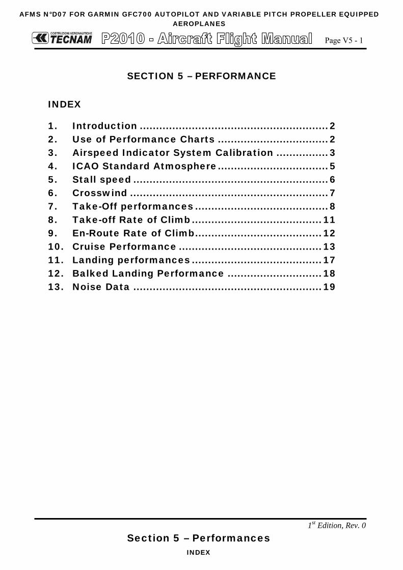
AFMS N°D07 FOR GARMIN GFC700 AUTOPILOT AND VARIABLE PITCH PROPELLER EQUIPPED AEROPLANES
Page V5 - 1
Section 5 – Performances INDEX
1st Edition, Rev. 0
SECTION 5 – PERFORMANCE
INDEX
1. Introduction .......................................................... 2 2. Use of Performance Charts .................................. 2 3. Airspeed Indicator System Calibration ................ 3 4. ICAO Standard Atmosphere .................................. 5 5. Stall speed ............................................................ 6 6. Crosswind ............................................................. 7 7. Take-Off performances ......................................... 8 8. Take-off Rate of Climb ........................................ 11 9. En-Route Rate of Climb ....................................... 12 10. Cruise Performance ............................................ 13 11. Landing performances ........................................ 17 12. Balked Landing Performance ............................. 18 13. Noise Data .......................................................... 19
AFMS N°D07 FOR GARMIN GFC700 AUTOPILOT AND VARIABLE PITCH PROPELLER EQUIPPED AEROPLANES
Page V5 - 2
Section 5 - Performances INTRODUCTION
1st Edition, Rev. 0
1. INTRODUCTION This section provides all necessary data for an accurate and comprehensive plan-ning of flight activity from takeoff to landing.
Data reported in graphs and/or in tables were determined using: “Flight Test Data” under conditions prescribed by EASA CS-23 regulation aircraft and engine in good condition average piloting techniques Each graph or table was determined according to ICAO Standard Atmosphere (ISA - s.l.); evaluations of the impact on performances were carried out by theoret-ical means for:
Airspeed External temperature Altitude Weight Runway type and condition
2. USE OF PERFORMANCE CHARTS Performances data are presented in tabular or graphical form to illustrate the effect of different variables such as altitude, temperature and weight. Given information is sufficient to plan the mission with required precision and safety.
Additional information is provided for each table or graph.

AFMS N°D07 FOR GARMIN GFC700 AUTOPILOT AND VARIABLE PITCH PROPELLER EQUIPPED AEROPLANES
Page V5 - 3
Section 5 - Performances AIRSPEED INDICATOR SYSTEM CALIBRATION
1st Edition, Rev. 0
3. AIRSPEED INDICATOR SYSTEM CALIBRATION
Normal Static Source
Graph shows calibrated airspeed VIAS as a function of indicated airspeed VCAS.
50
60
70
80
90
100
110
120
130
140
150
160
170
50 60 70 80 90 100 110 120 130 140 150 160
Indi
cate
d Ai
rspe
ed [K
IAS]
Calibrated Airspeed [KCAS]
Airspeed Indication System Calibration
Flap UP
Flap T/O
Flap LN
Fig. 5-1. Calibrated vs Indicated Airspeed
Example:
Given Find
KIAS 75.0
Flap: UP KCAS 74.7
Indicated airspeed assumes 0 as an instrument error NOTE

AFMS N°D07 FOR GARMIN GFC700 AUTOPILOT AND VARIABLE PITCH PROPELLER EQUIPPED AEROPLANES
Page V5 - 4
Section 5 - Performances AIRSPEED INDICATOR SYSTEM CALIBRATION
1st Edition, Rev. 0
Alternate Static Source
Alternate Static Air Open Vents Open Vents and Hot Air Open
IAS [kn]
HP [ft]
IAS [kn]
HP [ft]
IAS [kn]
HP [ft]
Pressure Altitude [ft]
IAS [kn]
FLAP UP
1000
70 75 1020 72 1010 72 1020
90 95 1020 92 1030 93 1020
110 115 1030 113 1020 112 1020
135 140 1040 139 1030 137 1030
FLAP T/O
60 63 1020 63 1020 62 1010
70 75 1020 73 1020 72 1020
90 94 1020 92 1020 92 1020
FLAP LND
60 62 1020 61 1020 61 1020
70 72 1020 72 1020 71 1020
90 92 1020 91 1020 91 1020
FLAP UP
5000
70 72 5020 72 5020 71 5020
90 94 5030 93 5020 92 5020
110 114 5030 113 5020 112 5020
133 137 5040 136 5030 135 5020
FLAP T/O
60 62 5010 62 5020 61 5010
70 74 5020 73 5020 72 5020
90 93 5030 93 5020 93 5020
FLAP LND
60 63 5030 62 5020 61 5000
70 72 5020 72 5010 71 5010
90 92 5020 92 5020 91 5010
FLAP UP
8000
70 72 8020 72 8020 71 8020
90 93 8030 92 8020 92 8020
110 113 8030 112 8020 112 8020
128 131 8040 130 8030 130 8020
FLAP T/O
60 62 8010 62 8020 61 8010
70 73 8020 72 8020 72 8020
90 92 8030 92 8020 92 8020
FLAP LND
60 61 8020 61 8020 61 8000
70 72 8010 71 8010 71 8010
90 92 8010 91 8010 91 8010

AFMS N°D07 FOR GARMIN GFC700 AUTOPILOT AND VARIABLE PITCH PROPELLER EQUIPPED AEROPLANES
Page V5 - 5
Section 5 - Performances ICAO STANDARD ATMOSPHERE
1st Edition, Rev. 0
4. ICAO STANDARD ATMOSPHERE
FIG. 5-2. ICAO CHART
Examples: Scope Given Find
Density Altitude: A: Pressure altitude = 1600ft B: Temperature = 20°C → C: Density Altitude = 2550ft
ISA Temperature: D: Pressure altitude = 1600ft → E: ISA Air Temperature = 12°C

AFMS N°D07 FOR GARMIN GFC700 AUTOPILOT AND VARIABLE PITCH PROPELLER EQUIPPED AEROPLANES
Page V5 - 6
Section 5 - Performances STALL SPEED
1st Edition, Rev. 0
5. STALL SPEED
Weight: 1160 kg (2557 lb) Throttle Lever: IDLE CG: Most Forward (19%) No ground effect
WEIGHT BANK ANGLE
STALL SPEED FLAPS 0° FLAPS T/O FLAPS FULL
[kg] ([lb]) [deg] KIAS KCAS KIAS KCAS KIAS KCAS
1160 (2557)
(FWD C.G.)
0 59 60 53 55 50 52 15 60 61 54 56 51 53 30 64 65 58 59 54 56 45 71 71 64 65 61 62 60 85 85 77 78 73 74
Altitude loss during conventional stall recovery, as demonstrated during flight tests is approximately 350 ft with banking below 15°.
NOTE
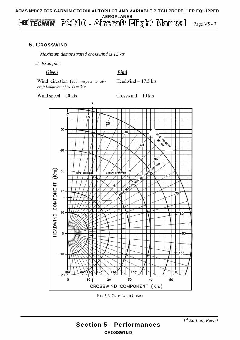
AFMS N°D07 FOR GARMIN GFC700 AUTOPILOT AND VARIABLE PITCH PROPELLER EQUIPPED
AEROPLANES
Page V5 - 7
Section 5 - Performances CROSSWIND
1st Edition, Rev. 0
6. CROSSWIND Maximum demonstrated crosswind is 12 kts
⇒ Example:
Given Find
Wind direction (with respect to air-craft longitudinal axis) = 30°
Headwind = 17.5 kts
Wind speed = 20 kts Crosswind = 10 kts
FIG. 5-3. CROSSWIND CHART

AFMS N°D07 FOR GARMIN GFC700 AUTOPILOT AND VARIABLE PITCH PROPELLER EQUIPPED
AEROPLANES
Page V5 - 8
Section 5 - Performances TAKE-OFF PERFORMANCES
1st Edition, Rev. 0
7. TAKE-OFF PERFORMANCES
To account for likely in service performance variations apply a factored to distances of 1.10
Weight = 1160 kg (2557 lb)
Flaps: T/O Speed at Lift-Off = 60 KIAS Speed Over 50ft Obstacle = 65 KIAS Throttle and Propeller Lever: Full Forward Runway: Paved
Corrections Headwind: -10 m for each kn Tailwind: +20 m for each kn Grass Runway: +10% to Ground Roll Runway slope: +10% to Ground Roll for each +1%
Pressure Altitude
Distance [m]
(Distance [ft]) Temperature [°C]
ISA [ft] -25 0 25 50
S.L. Ground Roll 234
(768) 295
(968) 364
(1194) 442
(1450) 336
(1102)
At 50 ft AGL 421 (1381)
526 (1726)
644 (2113)
776 (2546)
595 (1952)
1000 Ground Roll 256
(840) 322
(1056) 397
(1302) 482
(1581) 360
(1181)
At 50 ft AGL 458 (1503)
572 (1877)
701 (2300)
844 (2769)
637 (2090)
2000 Ground Roll 279
(915) 352
(1155) 434
(1424) 526
(1726) 387
(1270)
At 50 ft AGL 499 (1637)
622 (2041)
762 (2500)
918 (3012)
682 (2238)
3000 Ground Roll 305
(1001) 384
(1260) 474
(1555) 575
(1886) 415
(1362)
At 50 ft AGL 543 (1781)
678 (2224)
830 (2723)
1000 (3281)
731 (2398)
4000 Ground Roll 333
(1093) 420
(1378) 518
(1699) 628
(2060) 446
(1463)
At 50 ft AGL 591 (1939)
738 (2421)
904 (2966)
1089 (3573)
783 (2569)
5000 Ground Roll 364
(1194) 459
(1506) 566
(1857) 687
(2254) 480
(1575)
At 50 ft AGL 645 (2116)
805 (2641)
986 (3235)
1188 (3898)
840 (2756)
6000 Ground Roll 399
(1309) 502
(1647) 620
(2034) 752
(2467) 516
(1693)
At 50 ft AGL 703 (2306)
878 (2881)
1075 (3527)
1296 (4252)
901 (2956)
NOTE

AFMS N°D07 FOR GARMIN GFC700 AUTOPILOT AND VARIABLE PITCH PROPELLER EQUIPPED
AEROPLANES
Page V5 - 9
Section 5 - Performances TAKE-OFF PERFORMANCES
1st Edition, Rev. 0
Weight = 1060 kg (2337 lb) Flaps: T/O Speed at Lift-Off = 60 KIAS Speed Over 50ft Obstacle = 65 KIAS Throttle and Propeller Lever: Full Forward Runway: Paved
Corrections Headwind: -10 m for each kn Tailwind: +20 m for each kn Grass Runway: +10% to Ground Roll Runway slope: +10% to Ground Roll for each +1%
Pressure Altitude
Distance [m]
(Distance [ft]) Temperature [°C]
ISA [ft] -25 0 25 50
S.L. Ground Roll 189
(620) 238
(781) 293
(961) 356
(1168) 270
(886)
At 50 ft AGL 342 (1122)
427 (1401)
523 (1716)
630 (2067)
483 (1585)
1000 Ground Roll 206
(676) 259
(850) 320
(1050) 388
(1273) 290
(951)
At 50 ft AGL 372 (1220)
464 (1522)
569 (1867)
685 (2247)
517 (1696)
2000 Ground Roll 225
(738) 283
(928) 349
(1145) 424
(1391) 311
(1020)
At 50 ft AGL 405 (1329)
505 (1657)
619 (2031)
745 (2444)
554 (1818)
3000 Ground Roll 246
(807) 309
(1014) 382
(1253) 463
(1519) 334
(1096)
At 50 ft AGL 441 (1447)
550 (1804)
674 (2211)
812 (2664)
593 (1946)
4000 Ground Roll 268
(879) 338
(1109) 417
(1368) 506
(1660) 359
(1178)
At 50 ft AGL 480 (1575)
599 (1965)
734 (2408)
884 (2900)
636 (2087)
5000 Ground Roll 294
(965) 370
(1214) 456
(1496) 553
(1814) 386
(1266)
At 50 ft AGL 523 (1716)
653 (2142)
800 (2625)
964 (3163)
682 (2238)
6000 Ground Roll 321
(1053) 404
(1325) 499
(1637) 605
(1985) 416
(1365)
At 50 ft AGL 571 (1873)
713 (2339)
873 (2864)
1052 (3451)
732 (2402)
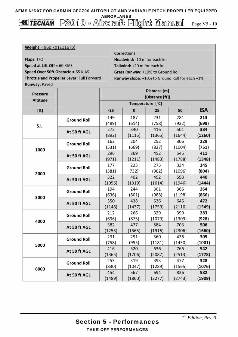
AFMS N°D07 FOR GARMIN GFC700 AUTOPILOT AND VARIABLE PITCH PROPELLER EQUIPPED
AEROPLANES
Page V5 - 10
Section 5 - Performances TAKE-OFF PERFORMANCES
1st Edition, Rev. 0
Weight = 960 kg (2116 lb)
Flaps: T/O Speed at Lift-Off = 60 KIAS Speed Over 50ft Obstacle = 65 KIAS Throttle and Propeller Lever: Full Forward Runway: Paved
Corrections Headwind: -10 m for each kn Tailwind: +20 m for each kn Grass Runway: +10% to Ground Roll Runway slope: +10% to Ground Roll for each +1%
Pressure Altitude
Distance [m]
(Distance [ft]) Temperature [°C]
ISA [ft] -25 0 25 50
S.L. Ground Roll 149
(489) 187
(614) 231
(758) 281
(922) 213
(699)
At 50 ft AGL 272 (892)
340 (1115)
416 (1365)
501 (1644)
384 (1260)
1000 Ground Roll 162
(531) 204
(669) 252
(827) 306
(1004) 229
(751)
At 50 ft AGL 296 (971)
369 (1211)
452 (1483)
545 (1788)
411 (1348)
2000 Ground Roll 177
(581) 223 732)
275 (902)
334 (1096)
245 (804)
At 50 ft AGL 322 (1056)
402 (1319)
492 (1614)
593 (1946)
440 (1444)
3000 Ground Roll 194
(636) 244
(801) 301
(988) 365
(1198) 264
(866)
At 50 ft AGL 350 (1148)
438 (1437)
536 (1759)
645 (2116)
472 (1549)
4000 Ground Roll 212
(696) 266
(873) 329
(1079) 399
(1309) 283
(928)
At 50 ft AGL 382 (1253)
477 (1565)
584 (1916)
703 (2306)
506 (1660)
5000 Ground Roll 231
(758) 291
(955) 360
(1181) 436
(1430) 305
(1001)
At 50 ft AGL 416 (1365)
520 (1706)
636 (2087)
766 (2513)
542 (1778)
6000 Ground Roll 253
(830) 319
(1047) 393
(1289) 477
(1565) 328
(1076)
At 50 ft AGL 454 (1489)
567 (1860)
694 (2277)
836 (2743)
582 (1909)

AFMS N°D07 FOR GARMIN GFC700 AUTOPILOT AND VARIABLE PITCH PROPELLER EQUIPPED
AEROPLANES
Page V5 - 11
Section 5 - Performances TAKE-OFF RATE OF CLIMB
1st Edition, Rev. 0
8. TAKE-OFF RATE OF CLIMB
To account for likely in service performance variations apply a factored to rate of climb of 0.90
Throttle Lever: Full Forward Propeller: 2600 RPM Flaps: Take-Off
Weight Pressure Altitude
Climb Speed
Vy
Rate of Climb [ft/min]
Temperature [°C]
ISA [kg] ([lb]) [ft] [KIAS] -25 0 25 50
1160 (2557)
S.L. 72 974 808 659 525 717
2000 71 848 684 538 406 617
4000 70 721 560 417 287 518
6000 69 596 437 296 169 419
8000 68 470 315 176 51 320
10000 67 345 193 56 -67 221
12000 67 221 71 -63 -184 122
14000 66 96 -51 -182 -300 23
1060 (2337)
S.L. 70 1118 943 787 647 848
2000 69 985 813 660 522 744
4000 69 853 684 533 397 640
6000 68 721 555 406 273 536
8000 68 589 426 280 149 431
10000 67 458 298 155 26 327
12000 66 327 170 29 -97 223
14000 66 197 43 -95 -220 119
960 (2116)
S.L. 69 1288 1103 937 787 1001 2000 69 1147 964 801 654 890 4000 68 1006 827 666 522 780 6000 68 866 689 532 390 669 8000 67 726 553 398 258 558
10000 66 586 416 264 127 448 12000 66 447 280 131 -3 337 14000 65 309 145 -2 -134 226
NOTE

AFMS N°D07 FOR GARMIN GFC700 AUTOPILOT AND VARIABLE PITCH PROPELLER EQUIPPED
AEROPLANES
Page V5 - 12
Section 5 - Performances EN-ROUTE RATE OF CLIMB
1st Edition, Rev. 0
9. EN-ROUTE RATE OF CLIMB
To account for likely in service performance variations apply a factored to rate of climb of 0.90
Throttle Lever: Full Forward Propeller: 2600 RPM Flaps: UP
Weight Pressure Altitude
Climb Speed
VY
Rate of Climb [ft/min]
Temperature [°C]
ISA [kg] ([lb]) [ft] [KIAS] -25 0 25 50
1160 (2557)
S.L. 82 1131 944 776 625 841
2000 81 989 804 639 491 729
4000 80 846 665 503 357 618
6000 79 705 526 367 224 506
8000 78 563 388 232 91 394
10000 77 423 251 97 -41 282
12000 76 282 113 -37 -173 171
14000 76 142 -23 -171 -305 59
1060 (2337)
S.L. 82 1284 1085 907 747 976
2000 81 1133 937 762 605 857
4000 80 982 789 618 463 739
6000 79 831 642 474 322 621
8000 78 682 496 330 181 502
10000 77 532 350 187 40 384
12000 76 383 204 45 -99 265
14000 75 235 59 -97 -239 147
960 (2116)
S.L. 81 1465 1251 1060 888 1134 2000 80 1302 1092 905 735 1007 4000 79 1140 934 749 583 880 6000 78 979 776 595 432 753 8000 77 818 619 441 281 625
10000 76 658 462 287 130 498 12000 75 498 306 134 -20 371 14000 74 339 150 -18 -170 244
NOTE

AFMS N°D07 FOR GARMIN GFC700 AUTOPILOT AND VARIABLE PITCH PROPELLER EQUIPPED
AEROPLANES
Page V5 - 13
Section 5 - Performances CRUISE PERFORMANCE
1st Edition, Rev. 0
10. CRUISE PERFORMANCE
Weight: 1160 kg (2557 lb) Pressure Altitude: 0 ft Mixture: FULL RICH
ISA – 30°C (-15°C) ISA (15°C) ISA + 30°C (45°C) RPM
MAP [inHg]
PWR [%MCP]
TAS [kn]
F.C. [gal/h] ([L/h])
PWR [%MCP]
TAS [kn]
F.C. [gal/h] ([L/h])
PWR [%MCP]
TAS [kn]
F.C. [gal/h] ([L/h])
2700 29.9 113 138 19.2 (72.7) 107 139 18.4 (69.7) 102 141 17.7 (67)
2600
29.9 109 136 18.7 (70.8) 103 138 17.9 (67.8) 98 139 17.2 (65.1)
28 101 132 17.6 (66.6) 96 134 16.9 (64) 91 135 16.3 (61.7)
26 90 126 16.1 (60.9) 85 127 15.4 (58.3) 81 128 14.9 (56.4)
24 79 120 14.7 (55.6) 75 121 14.1 (53.4) 71 121 13.6 (51.5)
22 69 113 13.3 (50.3) 65 113 12.8 (48.5) 62 113 12.4 (46.9)
20 59 105 11.9 (45) 56 104 11.5 (43.5) 53 103 11.1 (42)
2450
29.9 103 133 17.9 (67.8) 98 135 17.1 (64.7) 93 136 16.5 (62.5)
28 95 129 16.8 (63.6) 90 130 16.1 (60.9) 85 131 15.5 (58.7)
26 85 123 15.4 (58.3) 80 124 14.8 (56) 76 125 14.3 (54.1)
24 75 117 14.1 (53.4) 71 117 13.5 (51.1) 67 118 13.1 (49.6)
22 65 110 12.8 (48.5) 62 110 12.3 (46.6) 59 110 11.9 (45)
20 55 102 11.5 (43.5) 52 101 11.1 (42) 50 100 10.7 (40.5)
2350
29.9 100 131 17.4 (65.9) 94 133 16.7 (63.2) 90 134 16.1 (60.9)
28 91 127 16.2 (61.3) 86 128 15.6 (59.1) 82 129 15 (56.8)
26 81 121 15 (56.8) 77 122 14.4 (54.5) 73 123 13.9 (52.6)
24 72 115 13.7 (51.9) 68 115 13.1 (49.6) 65 115 12.7 (48.1)
22 62 108 12.4 (46.9) 59 108 12 (45.4) 56 107 11.6 (43.9)
20 53 99 11.1 (42) 50 98 10.7 (40.5) 48 96 10.4 (39.4)

AFMS N°D07 FOR GARMIN GFC700 AUTOPILOT AND VARIABLE PITCH PROPELLER EQUIPPED
AEROPLANES
Page V5 - 14
Section 5 - Performances CRUISE PERFORMANCE
1st Edition, Rev. 0
Weight: 1160 kg (2557 lb) Pressure Altitude: 3000 ft Mixture: FULL RICH
ISA – 30°C (-21°C) ISA (9°C) ISA + 30°C (39°C) RPM
MAP [inHg]
PWR [%MCP]
TAS [kn]
F.C. [gal/h] ([L/h])
PWR [%MCP]
TAS [kn]
F.C. [gal/h] ([L/h])
PWR [%MCP]
TAS [kn]
F.C. [gal/h] ([L/h])
2700 26.8 104 137 17.9 (67.8) 98 138 17.2 (65.1) 93 139 16.5 (62.5)
2600
26.8 100 135 17.4 (65.9) 94 136 16.7 (63.2) 90 137 16.1 (60.9)
26 96 133 16.9 (64) 90 134 16.2 (61.3) 86 135 15.6 (59.1)
24 85 126 15.4 (58.3) 80 127 14.8 (56) 76 128 14.3 (54.1)
22 76 128 14.3 (54.1) 70 120 13.5 (51.1) 67 120 13 (49.2)
20 63 111 12.6 (47.7) 60 111 12.1 (45.8) 57 110 11.7 (44.3)
18 53 101 11.1 (42) 50 99 10.7 (40.5) 47 97 10.4 (39.4)
2450
26.8 94 132 16.6 (62.8) 89 132 15.9 (60.2) 84 133 15.3 (57.9)
26 90 129 16.1 (60.9) 85 129 15.4 (58.3) 81 130 14.8 (56)
24 80 123 14.7 (55.6) 75 123 14.2 (53.8) 72 124 13.7 (51.9)
22 70 116 13.5 (51.1) 66 116 12.9 (48.8) 63 117 12.5 (47.3)
20 60 108 12.1 (45.8) 57 108 11.6 (43.9) 54 107 11.3 (42.8)
18 50 97 10.7 (40.5) 47 97 10.4 (39.4) 45 95 10.1 (38.2)
2350
26.8 90 130 16.1 (60.9) 85 131 15.5 (58.7) 81 131 14.9 (56.4)
26 86 127 15.6 (59.1) 81 128 15 (56.8) 77 129 14.4 (54.5)
24 77 121 14.3 (54.1) 72 122 13.8 (52.2) 69 122 13.3 (50.3)
22 67 114 13.1 (49.6) 64 114 12.6 (47.7) 60 114 12.2 (46.2)
20 57 105 11.7 (44.3) 54 105 11.3 (42.8) 51 103 11 (41.6)
18.5 50 98 10.7 (40.5) 47 95 10.4 (39.4) 45 92 10.1 (38.2)
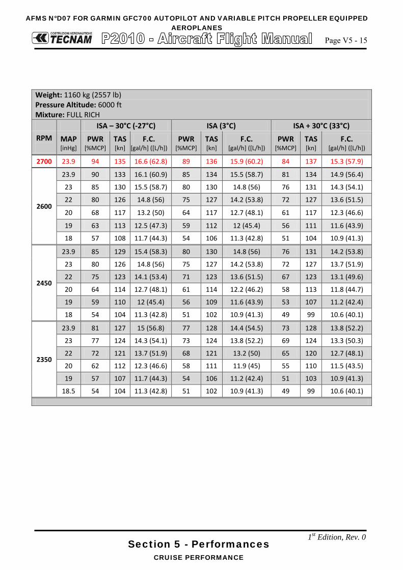
AFMS N°D07 FOR GARMIN GFC700 AUTOPILOT AND VARIABLE PITCH PROPELLER EQUIPPED
AEROPLANES
Page V5 - 15
Section 5 - Performances CRUISE PERFORMANCE
1st Edition, Rev. 0
Weight: 1160 kg (2557 lb) Pressure Altitude: 6000 ft Mixture: FULL RICH
ISA – 30°C (-27°C) ISA (3°C) ISA + 30°C (33°C) RPM
MAP [inHg]
PWR [%MCP]
TAS [kn]
F.C. [gal/h] ([L/h])
PWR [%MCP]
TAS [kn]
F.C. [gal/h] ([L/h])
PWR [%MCP]
TAS [kn]
F.C. [gal/h] ([L/h])
2700 23.9 94 135 16.6 (62.8) 89 136 15.9 (60.2) 84 137 15.3 (57.9)
2600
23.9 90 133 16.1 (60.9) 85 134 15.5 (58.7) 81 134 14.9 (56.4)
23 85 130 15.5 (58.7) 80 130 14.8 (56) 76 131 14.3 (54.1)
22 80 126 14.8 (56) 75 127 14.2 (53.8) 72 127 13.6 (51.5)
20 68 117 13.2 (50) 64 117 12.7 (48.1) 61 117 12.3 (46.6)
19 63 113 12.5 (47.3) 59 112 12 (45.4) 56 111 11.6 (43.9)
18 57 108 11.7 (44.3) 54 106 11.3 (42.8) 51 104 10.9 (41.3)
2450
23.9 85 129 15.4 (58.3) 80 130 14.8 (56) 76 131 14.2 (53.8)
23 80 126 14.8 (56) 75 127 14.2 (53.8) 72 127 13.7 (51.9)
22 75 123 14.1 (53.4) 71 123 13.6 (51.5) 67 123 13.1 (49.6)
20 64 114 12.7 (48.1) 61 114 12.2 (46.2) 58 113 11.8 (44.7)
19 59 110 12 (45.4) 56 109 11.6 (43.9) 53 107 11.2 (42.4)
18 54 104 11.3 (42.8) 51 102 10.9 (41.3) 49 99 10.6 (40.1)
2350
23.9 81 127 15 (56.8) 77 128 14.4 (54.5) 73 128 13.8 (52.2)
23 77 124 14.3 (54.1) 73 124 13.8 (52.2) 69 124 13.3 (50.3)
22 72 121 13.7 (51.9) 68 121 13.2 (50) 65 120 12.7 (48.1)
20 62 112 12.3 (46.6) 58 111 11.9 (45) 55 110 11.5 (43.5)
19 57 107 11.7 (44.3) 54 106 11.2 (42.4) 51 103 10.9 (41.3)
18.5 54 104 11.3 (42.8) 51 102 10.9 (41.3) 49 99 10.6 (40.1)

AFMS N°D07 FOR GARMIN GFC700 AUTOPILOT AND VARIABLE PITCH PROPELLER EQUIPPED
AEROPLANES
Page V5 - 16
Section 5 - Performances CRUISE PERFORMANCE
1st Edition, Rev. 0
Weight: 1160 kg (2557 lb) Pressure Altitude: 9000 ft Mixture: FULL RICH
ISA – 30°C (-33°C) ISA (-3°C) ISA + 30°C (27°C) RPM
MAP [inHg]
PWR [%MCP]
TAS [kn]
F.C. [gal/h] ([L/h])
PWR [%MCP]
TAS [kn]
F.C. [gal/h] ([L/h])
PWR [%MCP]
TAS [kn]
F.C. [gal/h] ([L/h])
2700 21.3 85 133 15.4 (58.3) 80 133 14.7 (55.6) 76 133 14.2 (53.8)
2600
21.3 81 130 15 (56.8) 77 131 14.3 (54.1) 73 131 13.8 (52.2)
20 73 124 13.8 (52.2) 69 124 13.3 (50.3) 65 123 12.8 (48.5)
19 67 119 13.1 (49.6) 64 119 12.6 (47.7) 60 118 12.1 (45.8)
18 62 114 12.3 (46.6) 58 113 11.9 (45) 55 111 11.5 (43.5)
2450
21.3 77 127 14.3 (54.1) 72 127 13.7 (51.9) 69 127 13.2 (50)
20 69 121 13.3 (50.3) 65 121 12.8 (48.5) 62 119 12.3 (46.6)
19 64 116 12.6 (47.7) 60 115 12.1 (45.8) 57 114 11.7 (44.3)
18 59 111 11.9 (45) 55 109 11.4 (43.2) 52 106 11.1 (42)
2350 19 66 121 12.9 (48.8) 62 120 12.4 (46.9) 59 117 11.9 (45)
18 60 115 12.2 (46.2) 57 113 11.7 (44.3) 54 110 11.3 (42.8)
Weight: 1160 kg (2557 lb) Pressure Altitude: 12000 ft Mixture: FULL RICH
ISA – 30°C (-39°C) ISA (-9°C) ISA + 30°C (21°C) RPM
MAP [inHg]
PWR [%MCP]
TAS [kn]
F.C. [gal/h] ([L/h])
PWR [%MCP]
TAS [kn]
F.C. [gal/h] ([L/h])
PWR [%MCP]
TAS [kn]
F.C. [gal/h] ([L/h])
2700 19 75 128 14.1 (53.4) 70 128 13.5 (51.1) 67 128 13 (49.2)
2600 19 72 126 13.7 (51.9) 68 126 13.2 (50) 64 125 12.7 (48.1)
18 66 121 13 (49.2) 63 120 12.4 (46.9) 59 118 12 (45.4)
2450 19 68 123 13.2 (50) 64 122 12.7 (48.1) 61 121 12.2 (46.2)
18 63 118 12.5 (47.3) 59 116 12 (45.4) 56 113 11.6 (43.9)
2350 19 66 121 12.9 (48.8) 62 120 12.4 (46.9) 59 117 11.9 (45)
18 60 115 12.2 (46.2) 57 113 11.7 (44.3) 54 110 11.3 (42.8)

AFMS N°D07 FOR GARMIN GFC700 AUTOPILOT AND VARIABLE PITCH PROPELLER EQUIPPED
AEROPLANES
Section 5 - Performances LANDING PERFORMANCES
1st Edition, Rev. 0
Page V5 - 17
11. LANDING PERFORMANCES
To account for likely in service performance variations apply a factored to distances of 1.67
Weight = 1160 kg (2557 lb) Flaps: LAND Short Final Approach Speed = 66 KIAS Throttle Lever: Idle Runway: Paved
Corrections
Headwind: -4 m for each kn
Tailwind: +13 m for each kn
Grass Runway: +10% to Ground Roll Runway slope: -3% to Ground Roll for each +1%
Pressure Altitude
Distance [m] (Distance [ft])
Temperature [°C] ISA [ft] -25 0 25 50
S.L. Ground Roll 204
(669) 225
(738) 245
(804) 266
(873) 237
(778)
At 50 ft AGL 488 (1601)
509 (1670)
529 (1736)
550 (1804)
521 (1709)
1000 Ground Roll 212
(696) 233
(764) 254
(833) 276
(906) 244
(801)
At 50 ft AGL 496 (1627)
517 (1696)
538 (1765)
560 (1837)
528 (1732)
2000 Ground Roll 220
(722) 242
(794) 264
(866) 286
(938) 251
(823)
At 50 ft AGL 504 (1654)
526 (1726)
548 (1798)
570 (1870)
535 (1755)
3000 Ground Roll 228
(748) 251
(823) 274
(899) 297
(974) 259
(850)
At 50 ft AGL 512 (1680)
535 (1755)
558 (1831)
581 (1906)
543 (1781)
4000 Ground Roll 236
(774) 260
(853) 284
(932) 308
(1010) 267
(876)
At 50 ft AGL 520 (1706)
544 (1785)
568 (1864)
592 (1942)
551 (1808)
5000 Ground Roll 245
(804) 270
(886) 295
(968) 320
(1050) 275
(902)
At 50 ft AGL 529 (1736)
554 (1818)
579 (1900)
604 (1982)
559 (1834)
6000 Ground Roll 255
(837) 280
(919) 306
(1004) 332
(1089) 284
(932)
At 50 ft AGL 539 (1768)
564 (1850)
590 (1936)
616 (2021)
568 (1864)
NOTE

AFMS N°D07 FOR GARMIN GFC700 AUTOPILOT AND VARIABLE PITCH PROPELLER EQUIPPED
AEROPLANES
Page V5 - 18
Section 5 - Performances BALKED LANDING PERFORMANCE
1st Edition, Rev. 0
12. BALKED LANDING PERFORMANCE
To account for likely in service performance variations apply a factored to rate of climb and to angle of climb of 0.90
Throttle and Propeller Lever: Full Forward Flaps: LAND Speed: 67 KIAS
Weight Pressure Altitude
Steady Gradient of Climb [%]
Temperature [°C]
ISA [kg] ([lb]) [ft] -25 0 25 50
1160 (2557)
S.L. 10.9 8.6 6.6 4.7 7.4
1000 10.0 7.8 5.7 3.9 6.7
2000 9.2 6.9 4.9 3.1 6.0
3000 8.3 6.1 4.1 2.3 5.3
4000 7.4 5.2 3.2 1.4 4.6
5000 6.6 4.4 2.4 0.6 3.9
6000 5.7 3.5 1.6 -0.2 3.3
7000 4.8 2.7 0.7 -1.0 2.6
1060 (2337)
S.L. 12.9 10.4 8.1 6.1 9.0
1000 11.9 9.4 7.2 5.2 8.3
2000 11.0 8.5 6.3 4.3 7.5
3000 10.0 7.6 5.4 3.4 6.8
4000 9.1 6.7 4.5 2.5 6.0
5000 8.1 5.7 3.6 1.7 5.3
6000 7.2 4.8 2.7 0.8 4.5
7000 6.2 3.9 1.8 -0.1 3.8
960 (2116)
S.L. 15.2 12.4 10 7.7 10.9
1000 14.1 11.4 9.0 6.7 10.1
2000 13.1 10.4 7.9 5.8 9.3
3000 12.0 9.3 6.9 4.8 8.4
4000 11.0 8.3 5.9 3.8 7.6
5000 10.0 7.3 4.9 2.8 6.8
6000 8.9 6.3 3.9 1.8 6.0
7000 7.9 5.3 2.9 0.9 5.2
NOTE

AFMS N°D07 FOR GARMIN GFC700 AUTOPILOT AND VARIABLE PITCH PROPELLER EQUIPPED
AEROPLANES
Page V5 - 19
Section 5 - Performances
1st Edition, Rev. 0
13. NOISE DATA Noise level, determined in accordance with ICAO/Annex 16 6th Ed., July 2011, Vol. I°, Chapter 10 and 14 CFR 36.1581(c), is 80.58 dB(A).
NOTE: No determination has been made by the Federal Aviation Administration that the noise levels of this aircraft are or should be acceptable or unacceptable for operation at, into, or out of, any airport.

Page D07-15
Section 9 – Supplements- Supplement no. D07
GARMIN GFC700 AUTOPILOT AND VARIABLE PITCH PROPELLER EQUIPPED AEROPLANES
Ed. 1, Rev.0
SECTION 6 – WEIGHT AND BALANCE Make sure you first applied instructions reported on the basic AFM,
Section 6 Weight and Balance
According to A/C configuration apply following pages replacement:
Supplement D07 WEIGHT AND BALANCE
page
AFM Section 6
page APV 6-11 thru 12 REPLACES 6-11 thru 12 of basic AFM, Section 6
Supplement D07: pages replacement instructions

Page D07-16
Section 9 – Supplements- Supplement no. D07
GARMIN GFC700 AUTOPILOT AND VARIABLE PITCH PROPELLER EQUIPPED AEROPLANES
Ed. 1, Rev.0
INTENTIONALLY LEFT BLANK

Section 6 – Weight and balance EQUIPMENT LIST
EQUIPMENT LIST 5The following is a list of equipment which may be installed in the P2010. The items marked with an "X" were installed on the airplane described at the be-ginning of the list and they are included in the Basic Empty Weight. It is the owner’s responsibility to retain this equipment list and amend it to re-flect changes in equipment installed in this airplane.
1st Edition, Rev. 0
AFMS N°D07 FOR GARMIN GFC700 AUTOPILOT AND VARIABLE PITCH PROPELLER EQUIPPEDAEROPLANES
Page V6-11

Section 6 – Weight and balance EQUIPMENT LIST
EQUIPMENT LIST AIRCRAFT S/N_____ DATE:
REF. DESCRIPTION P/N INST WEIGHT
[kg] ARM [M]
INSTRUMENTATION
A1 GARMIN G1000 IFDS
A2 MD 302 MID Continent 6420302-1 0.73 -0.69
A3 Compass C2400L4P 0.4 -0.69
A4 Pitch trim indicator – UMA instruments N0911S0U2DR00W 0.1 -0.69
A5 Digital Clock - Davtron M800-28V-BAT 0.1 -0.69
AVIONICS & MISCELLANEOUS B1 ELT-ACK E-04 0.73 1.61
B2 Front seats GEVEN E5-01-007-T01 (LH) E5-01-008-T01 (RH)
20
(10x2) 0.50
B3 Rear seats GEVEN E5-01-007-T01 (LH) E5-01-008-T01 (RH)
20
(10x2) 1.26
B4 Fire extinguisher 13-07655 0.8 -0.18
B5 First aid kit FIA270160 0.2 0.5
B6 Torch --------- 1 -0.18
B7 Battery GILL247- 24V -19Ah G247 19.3 3.05
B8 Fuel qty sender – Electronics international P-300C 0.15 0.5
B9 ADF Receiver – RA 3502 0505.757-912 1.5 3.05
B10 DME Transceiver - King KN 63 066-01070-0001 2 3.05
GARMIN GFC700 Autopilot:
B11 Servo pitch GSA 80 011-00877-20 1.44 5.3
B12 Servo roll GSA 80 011-00877-20 1.44 2.05
B13 Servo pitch trim GSA 81 011-00878-20 1.03 5.3
LIGHTS:
B14 Nav/POS/Strobe Light SH wing - Ultragalactica Aveo AVE-WPST R/G-54G 1 0.23
B15 Rudder Nav Light – PosiStrobe CT AVE-POSW-62G 1 5.5
B16 Landing/Taxy Light - WHELEN Mod 7167400 01-0771674-00 2 -1.52
PITOT STATIC:
B17 Pitot (Heated) - Falcon Gauge 24-AN5812-1 3 0.5
LANDING GEAR ACCESSORIES
C1 Nose Landing Gear Wheel Fairing 210-4-3001-401 1.2 -1.48
C2 Main Landing Gear Wheel Fairings 210-4-1020-001-L/R 3 (1.5x2) 0.66
1st Edition, Rev. 0
AFMS N°D07 FOR GARMIN GFC700 AUTOPILOT AND VARIABLE PITCH PROPELLER EQUIPPEDAEROPLANES
Page V6-12

Page D07-17
Section 9 – Supplements - Supplement no. D07
GARMIN GFC700 AUTOPILOT AND VARIABLE PITCH PROPELLER EQUIPPED AEROPLANES
Ed 1, Rev. 0
SECTION 7 – AIRFRAME AND SYSTEMS DESCRIPTION Make sure you first applied instructions reported on the basic AFM,
Section 7 Airframe and Systems Description
According to A/C configuration apply following pages replacement:
Supplement D07 AIRFRAME AND SYSTEMS DESCRIPTION
page
AFM Section 7
page APV 7-8 thru 11 REPLACES 7-8 thru 11 of basic AFM, Section 7
APV 7-16 REPLACES 7-16 of basic AFM, Section 7
APV 7-20 thru 21 REPLACES 7-20 thru 21 of basic AFM, Section 7
APV 7-27 REPLACES 7-27 of basic AFM, Section 7
APV 7-33 REPLACES 7-33 of basic AFM, Section 7
APV 7-36 REPLACES 7-36 of basic AFM, Section 7
Supplement D07: pages replacement instructions

Page D07-18
Section 9 – Supplements - Supplement no. D07
GARMIN GFC700 AUTOPILOT AND VARIABLE PITCH PROPELLER EQUIPPED AEROPLANES
Ed 1, Rev. 0
INTENTIONALLY LEFT BLANK

Section 7 – Airframe and Systems description FLIGHT CONTROLS
3 FLIGHT CONTROLS Aircraft flight controls are operated through conventional stick and rudder pedals. Longitudinal control acts through a system of push-rods and is equipped with a trim tab. a cable control circuit is confined within the cabin and it is connected to a pair of push-pull rod systems positioned in each main wing which control ailerons differen-tially. Aileron trimming is carried out on ground through a small tab positioned on left aileron. Flaps are extended via an electric servo actuator controlled by a switch on the instru-ment panel. Flaps act in continuous mode; the indicator displays three markings relat-ed to 0°, takeoff (T/O) and landing (FULL) positions. A breaker positioned on the right side of the instrument panel protects the electric circuit. The control of the stabilator trim is operated by means of both a control wheel, locat-ed between the two front seats that acts directly on the control cables, and an electri-cal actuator controlled by a switch located on the control wheel; stabilator trim posi-tion is displayed on a dedicated analogue indicator located on the LH area of the in-strument panel. Rudder Trimming device for lateral control is provided by means of an electrical ac-tuator controlled by a rocker switch located near the pitch trim wheel; the surface is con-nected to a potentiometer linked to a rudder trim indicator included in the Gar-min G1000 EIS (Engine Indication System).
1st Edition, Rev. 0
AFMS N°D07 FOR GARMIN GFC700 AUTOPILOT AND VARIABLE PITCH PROPELLER EQUIPPEDAEROPLANES
Page APV 7-8
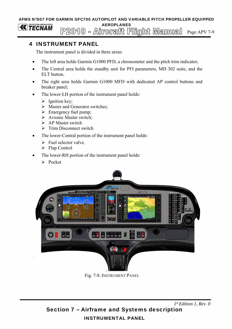
Section 7 – Airframe and Systems description INSTRUMENTAL PANEL
4 INSTRUMENT PANEL The instrument panel is divided in three areas:
• The left area holds Garmin G1000 PFD, a chronometer and the pitch trim indicator; • The Central area holds the standby unit for PFI parameters, MD 302 suite, and the
ELT button. • The right area holds Garmin G1000 MFD with dedicated AP control buttons and
breaker panel; • The lower-LH portion of the instrument panel holds:
Ignition key; Master and Generator switches; Emergency fuel pump; Avionic Master switch; AP Master switch Trim Disconnect switch
• The lower-Central portion of the instrument panel holds: Fuel selector valve. Flap Control
• The lower-RH portion of the instrument panel holds: Pocket
Fig. 7-8. INSTRUMENT PANEL
AFMS N°D07 FOR GARMIN GFC700 AUTOPILOT AND VARIABLE PITCH PROPELLER EQUIPPEDAEROPLANES
Page APV 7-9
1st Edition 1, Rev. 0

Section 9 – Supplements
ENGINE CONTROLS
4.1 ENGINE CONTROL LEVER
Engine handling is via three levers: Throttle, RPM lever, Mixture control lever. They’re situated on the center control; the use of “front/forward” and “rear/backward” is defined in relation to the direction of flight (longitudinal). Mixture control lever This lever (right hand lever with red handle) controls the fuel-air mixture, which is supplied to the engine. With the lever full forward, extra fuel is being supplied to the engine which at higher performance setting contributes to engine cooling. In cruise, the mixture should be made leaner in order to reach the appropriate fuel-air mixture. The leaning procedure is given in Chapter 4.
Lever forward (RICH) >> Mixture rich (in fuel) Lever to rear (LEAN) >>Mixture lean (in fuel)
To shut off the engine the mixture control lever is pulled to the rear stop: air without fuel is drawn into the cylinders that shuts down. Throttle This lever (left hand with large knob) is used to control manifold pressure (MAP). High manifold pressure means a large quantity of fuel-air mixture is being supplied to engine, while low manifold pressure means a lesser quantity of fuel-air mixture is being supplied. Propeller lever By means of this lever (central lever with blue handle) the propeller governor controls the propeller pitch, and consequently engine RPM. A selected RPM is held constant by the governor independent of the airspeed and the throttle setting.
Lever forward (HIGH RPM) = fine pitch Lever rearward (LOW RPM) = coarse pitch
Following a defect in governor or oil system, the blades go to the finest possible pitch (maximum RPM), thus allowing continuation of the flight.
CAUTION
Following failure of the governor or a serious drop in oil pressure, the RPM should be adjusted using the throttle. Every effort should be made not to exceed 2700 RPM.
CAUTION
The throttle and RPM lever should be moved slowly, in order to avoid over-speed and excessively rapid RPM changes.
AFMS N°D07 FOR GARMIN GFC700 AUTOPILOT AND VARIABLE PITCH PROPELLER EQUIPPEDAEROPLANES
Page APV 7-10
1st Edition, Rev. 0

Section 9 – Supplements
ENGINE CONTROLS
4.2 ALTERNATE AIR
Alternate Air knob is located on the central pedestal; when the knob is fully pulled outward from the instrument panel, injectors receive maximum hot air. During nor-mal operation, the knob is set in OFF position.
4.3 DEFROST AND CABIN HEAT
Two knobs, located on the lower side of the central pedestal, allow Defrost and Cabin Heat function. The one marked as “Defrost and Cabin Heat” allows hot air to perform windshield defrost and partially cabin heat. The cabin heat control knob, when fully outward, allows cabin to receive maximum hot air. When both cabin heat and defrost and cabin heat are pulled, air is partitioned.
Fig. 7-9. CENTRAL PEDESTAL
1st Edition, Rev. 0
AFMS N°D07 FOR GARMIN GFC700 AUTOPILOT AND VARIABLE PITCH PROPELLER EQUIPPEDAEROPLANES
Page APV 7-11

Section 9 – Supplements
POWERPLANT
7. POWERPLANT
7.1. ENGINE
Manufacturer …………………………… Lycoming Textron Model …………………………………... IO-360-M1A Type Certificate ………………………... EASA TCDS no. IM.E.032 Engine type …………………………….. Fuel injected (IO), direct drive, four cylinder
horizontally opposed, air cooled with down exhaust outlets.
Maximum power ……. Maximum continuous power …………...
134.0 kW (180hp) @ 2700 rpm 129.2 kW (173.3hp) @ 2600 rpm
Oil Consumption Operation RPM HP Max.
Oil Cons. Qts./Hr.
*Max. Cyl. Head
Temp. Normal Rated 2700 180 .80 500°F (260°C) Performance Cruise (75%) 2450 135 .45 500°F (260°C) Economy Cruise (60R Rated) 2350 117 .39 500°F (260°C)
7.2. PROPELLER
Manufacturer ………………………….. MT Propeller Model …………………………………. MTV-15-B/193-52 Type Certificate ……………………….. EASA TCDS no. P.098 Blades/hub …………………………….. wood/composite 2-blades – aluminium hub Diameter ………………………………. 1930 mm (6,33 ft) no reduction allowed Type …………………………………… Variable pitch
Governor Manufacturer ………………………….. MT Propeller Model …………………………………. P-860-23: Type Hydraulic
AFMS N°D07 FOR GARMIN GFC700 AUTOPILOT AND VARIABLE PITCH PROPELLER EQUIPPEDAEROPLANES
Page APV 7-16
1st Edition, Rev. 0

Section 7 – Airframe and Systems description ELECTRICAL SYSTEM
9 ELECTRICAL SYSTEM Primary DC power is provided by an external alternator with a 28 VDC output, rated of 70 Amps @ 2700 rpm. During normal operations, it recharges the bat-tery. Secondary DC power is provided by a lead type battery (GILL G-247) which provides the energy necessary for feeding the essential electrical loads in the event of an alternator failure. The switch between the energy sources is automatic and no action is required in order to activate the alternate energy source. For ground maintenance and/or starting, an external power socket is provided. The alternator and battery are connected to the battery bus in order to provide energy for the electric equipment. Each electrically fed instrument is connected to a dedicated circuit breaker which protects the cable from the battery bus to the associated electric equip-ment.
WARNING
If the Ignition is in the position L, R, or BOTH, an accidental movement of the propeller may start the engine with possible danger for bystanders.
In the following figure is presented the electrical system architecture.
AFMS N°D07 FOR GARMIN GFC700 AUTOPILOT AND VARIABLE PITCH PROPELLER EQUIPPEDAEROPLANES
Page APV 7-20
1 st Edition, Rev. 0

Section 7 – Airframe and Systems description ELECTRICAL SYSTEM
FIG.7-15. ELECTRICAL SYSTEM ARCHITECTURE
12.3 STALL WARNING SYSTEM The aircraft is equipped with a stall warning system consisting of a sensor locat-ed on the right wing leading edge connected to a warning horn located near the instrument panel.
AFMS N°D07 FOR GARMIN GFC700 AUTOPILOT AND VARIABLE PITCH PROPELLER EQUIPPEDAEROPLANES
Page APV 7-21
1st Edition, Rev. 0

AFMS N°D07 FOR GARMIN GFC700 AUTOPILOT AND VARIABLE PITCH PROPELLER EQUIPPED AEROPLANES
Page APV 7-27
Section 9 – Supplements -
INTERNAL LIGHTS
11.2 INTERNAL LIGHTS On the cabin ceiling are located four map lights, two in the front area (pilot) and two in the rear area (passengers). In the central area of the cabin ceiling is located a spot light used to illuminate the pedestal during night flight operations. All ceiling lights are dimmable by a dedicat-ed dimmer.
FIG.7-18. CABIN CEILING LIGHTS LAYOUT
The instrument panel can be illuminated by 8 incandescence light strips, all dimma-ble.
FIG.7-19. INSTRUMENT PANEL LIGHTS LAYOUT
FWD
From mid MAP light (ceiling)
1st Edition, Rev 0

Section 7 – Airframe and Systems description
PLACARDS
ELT unit position placard:
Breaker Panel placards:
AFMS N°D07 FOR GARMIN GFC700 AUTOPILOT AND VARIABLE PITCH PROPELLER EQUIPPEDAEROPLANES
Page APV 7-33
1st Edition, Rev. 0

Section 9 – Supplements
PLACARDS
Pedestal placards:
AFMS N°D07 FOR GARMIN GFC700 AUTOPILOT AND VARIABLE PITCH PROPELLER EQUIPPEDAEROPLANES
Page APV 7-36
1st Edition, Rev. 0

Page D07-19
Ed. 1Rev 0
Section 9 – Supplements - Supplement no. D07
GARMIN GFC700 AUTOPILOT AND VARIABLE PITCH PROPELLER EQUIPPED AEROPLANES
SECTION 8 – GROUND HANDLING & SERVICE Make sure you first applied instructions reported on the basic AFM,
Section 8 Ground Handling & Service
According to A/C configuration refer to the basic AFM, Section 8 – Ground Handling & Service
Supplement D07: pages replacement instructions

Page D07-20
Ed. 1Rev 0
Section 9 – Supplements - Supplement no. D07
GARMIN GFC700 AUTOPILOT AND VARIABLE PITCH PROPELLER EQUIPPED AEROPLANES
INTENTIONALLY LEFT BLANK