Automatic Beam Alignment for the Mode-Cleaner Cavities of GEO 600
8
Automatic beam alignment for the mode-cleaner cavities of GEO 600 Hartmut Grote, Gerhard Heinzel, Andreas Freise, Stefan Goßler, Benno Willke, Harald Lu ¨ ck, Harry Ward, Morag M. Casey, Kenneth A. Strain, David Robertson, Jim Hough, and Karsten Danzmann The automatic alignment system for the two suspended, triangular mode-cleaner cavities of the gravi- tational wave detector GEO 600 has been in continuous operation since the spring of 2001. A total of 20 angular degrees of freedom are controlled by feedback loops with almost no manual alignment having been required since installation. Error signals for the eight most important degrees of freedom are obtained with the differential wave-front sensing technique. We describe the sensing system, the control topology, and the performance of the automatic alignment system. A continuous locking stretch of more than 120 h has been achieved. © 2004 Optical Society of America OCIS codes: 120.3180, 230.0040. 1. Introduction Laser interferometric gravitational wave detectors are the most precise interferometers ever built. To allow for outstanding displacement sensitivities, the mirrors need to be isolated from seismic motion. For this purpose the cavity mirrors and beam-steering mirrors are suspended as pendulums inside a vac- uum system. Although this gives good attenuation of longitudinal and angular motions of the suspended components in the measurement band of a gravita- tional wave detector e.g., 50 Hz–1kHz, the motion is enhanced at the pendulum resonant frequencies typ- ically around 1 Hz. Moreover, suspended compo- nents are subject to larger drifts over long time periods than they would if rigidly mounted. For achieving stable operation in the long term with suspended optical cavities, an automatic angu- lar alignment system is required for two degrees of freedom of each suspended mirror. This paper describes the automatic alignment sys- tem implemented for the two suspended mode- cleaner cavities of GEO 600. 1 Mode cleaners are used to suppress higher-order TEM modes of the la- ser beam used for the main length-sensing inter- ferometer of a gravitational wave detector. In addition, they provide temporal filtering of amplitude and frequency fluctuations. Each of the GEO 600 mode cleaners consists of three mirrors forming a triangular optical cavity. Together with two beam-steering mirrors for each mode cleaner, a total of ten suspended mirrors, and thus 20 angular degrees of freedom, has to be aligned. Vertical pointing of a laser beam is referred to as the pitch and horizontal pointing as the yaw motion of an associated mirror. Roll motion around the optical axis has no effect on path length and alignment. The goal of the automatic alignment system is to keep the fundamental optical eigenmode of each cav- ity colinear with the incoming beam and to center all beam spots on the corresponding mirrors. Both of these tasks have to be performed reliably over long time periods, with as little human interaction as pos- sible to permit continuous long-term operation of a gravitational wave observatory. Aligning the cavity axis with the incoming beam is the most important alignment task in that this yields maximized power transmission and minimizes the coupling of incident laser beam geometry fluctuations into the transmitted light power. It is necessary to H. Grote [email protected], A. Freise, and S. Goßler are with the Institut fu ¨ r Atom- und Moleku ¨ lphysik, Universita ¨ t Hannover, Callinstrasse 38, D-30167 Hannover, Germany. G. Heinzel is with the Max-Planck-Institut fu ¨ r Gravitationsphysik, Teilinstitut Hannover, Callinstrasse 38, D-30167 Hannover, Germany. B. Willke, H. Lu ¨ ck, and K. Danzmann are with the Institut Fu ¨ r Atom- und Moleku ¨ lphysik and the Max-Planek-Institut fu ¨ r Gravitation- sphysik. H. Ward, M. M. Casey, K. A. Strain, D. Robertson, and J. Hough are with Department of Physics and Astronomy, Univer- sity of Glasgow G128QQ, Scotland, U.K. Received 8 December 2003; revised manuscript received 8 De- cember 2003; accepted 17 December 2003. 0003-693504091938-08$15.000 © 2004 Optical Society of America 1938 APPLIED OPTICS Vol. 43, No. 9 20 March 2004
Transcript of Automatic Beam Alignment for the Mode-Cleaner Cavities of GEO 600

Ac
HHJ
1
Laamtmuocteinp
w
tCwHWusJs
c
1
utomatic beam alignment for the mode-cleaneravities of GEO 600
artmut Grote, Gerhard Heinzel, Andreas Freise, Stefan Goßler, Benno Willke,arald Luck, Harry Ward, Morag M. Casey, Kenneth A. Strain, David Robertson,im Hough, and Karsten Danzmann
The automatic alignment system for the two suspended, triangular mode-cleaner cavities of the gravi-tational wave detector GEO 600 has been in continuous operation since the spring of 2001. A total of 20angular degrees of freedom are controlled by feedback loops with almost no manual alignment havingbeen required since installation. Error signals for the eight most important degrees of freedom areobtained with the differential wave-front sensing technique. We describe the sensing system, thecontrol topology, and the performance of the automatic alignment system. A continuous locking stretchof more than 120 h has been achieved. © 2004 Optical Society of America
OCIS codes: 120.3180, 230.0040.
lf
tcusfaa
tTmtVpaa
kibttsg
tmci
. Introduction
aser interferometric gravitational wave detectorsre the most precise interferometers ever built. Tollow for outstanding displacement sensitivities, theirrors need to be isolated from seismic motion. For
his purpose the cavity mirrors and beam-steeringirrors are suspended as pendulums inside a vac-
um system. Although this gives good attenuationf longitudinal and angular motions of the suspendedomponents in the measurement band of a gravita-ional wave detector �e.g., 50 Hz–1kHz�, the motion isnhanced at the pendulum resonant frequencies �typ-cally around 1 Hz�. Moreover, suspended compo-ents are subject to larger drifts over long timeeriods than they would if rigidly mounted.For achieving stable operation in the long termith suspended optical cavities, an automatic angu-
H. Grote �[email protected]�, A. Freise, and S. Goßler are withhe Institut fur Atom- und Molekulphysik, Universitat Hannover,allinstrasse 38, D-30167 Hannover, Germany. G. Heinzel isith the Max-Planck-Institut fur Gravitationsphysik, Teilinstitutannover, Callinstrasse 38, D-30167 Hannover, Germany. B.illke, H. Luck, and K. Danzmann are with the Institut Fur Atom-
nd Molekulphysik and the Max-Planek-Institut fur Gravitation-physik. H. Ward, M. M. Casey, K. A. Strain, D. Robertson, and. Hough are with Department of Physics and Astronomy, Univer-ity of Glasgow G128QQ, Scotland, U.K.Received 8 December 2003; revised manuscript received 8 De-
ember 2003; accepted 17 December 2003.0003-6935�04�091938-08$15.00�0© 2004 Optical Society of America
938 APPLIED OPTICS � Vol. 43, No. 9 � 20 March 2004
ar alignment system is required for two degrees ofreedom of each suspended mirror.
This paper describes the automatic alignment sys-em implemented for the two suspended mode-leaner cavities of GEO 600.1 Mode cleaners aresed to suppress higher-order TEM modes of the la-er beam used for the main length-sensing inter-erometer of a gravitational wave detector. Inddition, they provide temporal filtering of amplitudend frequency fluctuations.Each of the GEO 600 mode cleaners consists of
hree mirrors forming a triangular optical cavity.ogether with two beam-steering mirrors for eachode cleaner, a total of ten suspended mirrors, and
hus 20 angular degrees of freedom, has to be aligned.ertical pointing of a laser beam is referred to as theitch and horizontal pointing as the yaw motion of anssociated mirror. Roll motion around the opticalxis has no effect on path length and alignment.The goal of the automatic alignment system is to
eep the fundamental optical eigenmode of each cav-ty colinear with the incoming beam and to center alleam spots on the corresponding mirrors. Both ofhese tasks have to be performed reliably over longime periods, with as little human interaction as pos-ible to permit continuous long-term operation of aravitational wave observatory.Aligning the cavity axis with the incoming beam is
he most important alignment task in that this yieldsaximized power transmission and minimizes the
oupling of incident laser beam geometry fluctuationsnto the transmitted light power. It is necessary to

py�tsunwwti
fcctfdlo
tfimnaaw
w�G
titm6t
as
2
Fcta
cbm�Tmsottmat
dTatme
tEftaFBcp
Fgci
roduce the required alignment error signals, whichield information about the four degrees of freedomtwo angles and two lateral displacements� describinghe relative orientation of a cavity axis to the corre-ponding input beam. To obtain such signals, wese the differential wave-front sensing �DWS� tech-ique �see, e.g., Refs. 2–4�. It is an extension of theidely known Pound–Drever–Hall sensing scheme,5hich is used in separate control loops to keep the
wo GEO 600 mode cleaners on resonance with thencident laser light.
In the Pound–Drever–Hall scheme the phase dif-erence between the interfering wave fronts of theavity input beam and the beam leaking out of theavity is averaged over the whole cross section ofhese two interfering beams. The resulting signal ised to an appropriate feedback loop to keep the inci-ent light in resonance with the cavity. That thisoop is working correctly is an assumption through-ut this paper.The DWS technique uses split photodiodes to de-
ermine the angles between the two interfering waveronts by subtraction of the phase difference of thenterfering beams on the appropriate photodiode seg-
ents. If two such photodiodes are used �locatedear and far from the beam waist�, the four measuredngles between the wave fronts can be translated intongular and parallel displacements of the cavity axisith respect to the axis of the incoming beam.The theory for obtaining alignment error signalsith the DWS technique has been published already
see, e.g., Ref. 2�, and the alignment signals for theEO 600 mode cleaners have also been calculated.6After giving a short overview of the optical setup of
he mode cleaners �Section 2�, we describe the exper-mental setup of the alignment system �Section 3�,he alignment-control loop design, and the perfor-ance �Section 4� of the two mode cleaners of GEO
00. An important new �to our knowledge� result ofhis research is the successful long-term operation
nd excellent robustness achieved with the describedystem.
. Optical Setup of the GEO 600 Mode Cleaners
igure 1 shows the optical setup of the two mode-leaner cavities of GEO 600 within the vacuum sys-em. The mode-cleaner cavities and suspensionsre described in detail in a companion paper.7Light from the laser bench enters the vacuum
hamber TCMa from the lower right, is directed by aeam-steering mirror �BDIMC1�, and enters the firstode cleaner �MC1�, consisting of two flat mirrors
MMC1a and MMC1c� and a curved mirror �MMC1b�.he light leaves MC1 via MMC1c and is steered byirror BDOMC1. Phase modulation is applied by a
uspended electro-optic modulator �PCMC2�. An-ther suspended mirror �BDIMC2� steers the beamoward the second mode cleaner �MC2�, consisting ofwo flat mirrors �MMC2a and MMC2c� and a curvedirror �MMC2b�. The light leaves MC2 via MMC2b
nd is finally directed toward the main interferome-er by mirror BDOMC2 in chamber TCMb.
All beams required for the alignment system arerawn, together with corresponding photodetectors.he photodetectors PDAMC1, PDIMC2, and PDIPRre single �four-element� spot-position-detecting pho-odiodes, whereas PDMC1 and PDMC2 symbolizeore complex arrangements, each using two �four-
lement� photodiodes.The detection setup PDMC1 and PDMC2 provide
he four DWS signals needed for each mode cleaner.rror signals for the remaining 12 angular degrees of
reedom of the ten suspended mirrors are taken fromhe beam spot positions on all five detectors shownnd an additional spot-position sensor �not shown inig. 1�, detecting the position of the beam steered byDOMC2. Spot-position information is needed toenter a beam on its respective mirror. This is es-ecially important for cavity mirrors, in order to min-
ig. 1. Optical setup of the two GEO 600 mode-cleaner cavities within the vacuum system. Arrows denote directions of light propa-ation. All photodetectors �including PDAMC1� are located outside the vacuum envelope. The distance between the two vacuumhambers is 4 m, resulting in a round-trip length of each of the two mode cleaners of approximately 8 m. The first triangular mode cleaners formed by MMC1a, MMC1b, and MMC1c and the second by MMC2a, MMC2b, and MMC2c.
20 March 2004 � Vol. 43, No. 9 � APPLIED OPTICS 1939

il
3
A
FiMlduptcM
FrlTh
ttst
t
tsqywfeAaamtanMnrOnMsaimeItpt
uoP
ttdMEhbTo
cfF
B
Etdtadtdpebt
FDGAdenote the number of degrees of freedom controlled by each path.
1
mize coupling of yaw and pitch noise of mirrors intoength changes of the optical cavity.
. Automatic Alignment Setup
. Overview
igure 2 shows the most important part of the exper-mental setup for the automatic alignment system of
C1. To allow the use of the Pound–Drever–Hallocking and DWS, we have had the laser beam inci-ent on MMC1a modulated in phase at 25.2 MHz bysing the electro-optic modulator PCMC1. Thehase-modulation frequency is chosen to ensure thathe resulting sidebands are far from resonant in theavity. �The free spectral ranges are 37.48 MHz forC1 and 37.16 MHz for MC2�.The beam leaving mirror MMC1a downward in
ig. 2 consists of the interfering fields of the directlyeflected part of the input beam �Ei� and the fieldeaking out of the cavity �Ec� and is denoted Ei � Ec.his beam is split by the beam splitter BS1 �whichas a transmission of approximately 50%�.The components G1 and G2 �described in Subsec-
ion 3.B� are beam-deflecting devices used to centerhe beams on photodetectors D1 and D2. The corre-ponding control loops are called the centering con-rol.
Lenses L1 and L2 in the light path to D2 are usedo project beam E � E into the far field �see Subsec-
i c940 APPLIED OPTICS � Vol. 43, No. 9 � 20 March 2004
ion 3.D�. Each of the detectors D1 and D2 �de-cribed in more detail in Subsection 3.C� consists of auadrant photodiode with associated electronics toield information about the beam spot position,hereas the angle between the interfering wave
ronts �the DWS signal� is available after the coher-nt demodulation performed by mixers M1 and M2.ppropriate linear combinations of the DWS signalsre then processed by analog electronic circuits A1nd A2 to generate feedback signals to individualirrors. �See Subsection 3.D for a description of
his orthogonalization process.� Amplified with anppropriate gain and frequency response, these sig-als are fed back to mirror MMC1b and mirrorsMC1a � MMC1c, where MMC1a � MMC1c de-
otes a differential mode motion of this pair of mir-ors. These loops are referred to as DWS control.wing to the cavity geometry, the DWS system can-ot distinguish between misalignments of mirrorMC1a and mirror MMC1c. Consequently, the
ame feedback is applied to both mirrors with theppropriate sign for each mirror. We call the result-ng motion a differential mode motion of these two
irrors. Note that the relative signs of the differ-ntial modes are different for yaw and pitch motion:n a differential yaw motion the two mirrors are ro-ated in different directions, whereas a differentialitch mode is performed by a pitch of both mirrors inhe same direction.
The dashed lines denote slow digital feedback loopssed for spot-position control. The beam is centeredn MMC1b by feeding the spot-position signal fromDAMC1 back to mirror BDIMC1.There remains two more degrees of freedom of the
hree cavity mirrors to be controlled. These are thewo common modes of mirrors MMC1a and MMC1c,enoted by MMC1a � MMC1c. Variations ofMC1a � MMC1c show up in the direction of beam
i � Ec. As this beam is centered on D1 by G1 withigh bandwidth, the information of the direction ofeam Ei � Ec is contained in the feedback to G1.his signal is fed back to MMC1a � MMC1c by an-ther spot-position control.The alignment setup for the second GEO 600 mode
leaner is identical, by use of a phase-modulationrequency of 13 MHz, which is applied by PCMC2 inig. 1.
. Beam-Centering Scanners
xperience on the Garching 30-m prototype4 showedhat it is useful to center the beam Ei � Ec on theetecting quadrant photodiodes with auxiliary con-rol loops. This permits easier lock acquisition of thelignment system and compensates for drifts of theetected beam with respect to the photodetector. Inhe case of three-mirror ring cavities there is an ad-itional potential problem: The cavity beam can beerfectly aligned to the incoming beam but withoutnforcing a unique direction of the beam Ei � Ec. Ifeam Ei � Ec is not centered on the quadrant diodes,he DWS signal size decreases and can contain offsets
ig. 2. Automatic alignment system layout for one mode cleaner.etails of the purpose of lenses L1 and L2, galvanometer scanners1 and G2, photodiodes D1 and D2, mixers M1 and M2, and adders1 and A2 are given in the text. The numbers at the control boxes

cfasa2ibwWtTatlaai
gGoppTo1tDstpesac
ccTta
C
TPtntbdt
UcIcsttntttZ
�tp�tIugndrapeocit
rhadiqpp3
bwseudtd
FTrt
aused by higher transverse modes �e.g., TEM20�. If,or example, beam Ei � Ec deviates from the center ofdiode by one beam radius, 86% �1 � e�2� of the DWS
ignal is lost. If the centering scanners are not used,n angular pointing error of beam Ei � Ec of roughly00 �rad leads to such a decentering on detector D2n Fig. 2. By use of the scanners, beam Ei � Ec cane moved up to �2000 �rad while the beam is stillell centered on D2, yielding the correct DWS signal.hen the beam-pointing error exceeds 2000 �rad,
he beam gets cut at the edges of the scanner mirrors.hese numbers show that the dynamic range of thelignment-detection system is increased by morehan a factor of 10 owing to the scanners. Such aarge range allows the successful acquisition of theutomatic alignment system even in highly mis-ligned initial states. This is demonstrated by Fig. 5n Subsection 4.B.
G1 and G2 in Fig. 2 consist of two commercialalvanometer scanners �General Scanning Inc., Type102�, each carrying small �10 mm � 15 mm� mirrorsn their axes that can be rotated by �2 deg. Witherpendicular mounting of two scanners, one pair canoint the reflected beam in two degrees of freedom.he centering loops in Fig. 2 control the spot positionn the respective diodes with a bandwidth of aroundkHz. The gain of this analog feedback loop is con-
inuously normalized for the light power available on1 and D2 by analog division of the position error
ignals. The centering loops for D1 and D2 are au-omatically switched off while the detected lightower exceeds an upper or lower threshold. �Forxample, the scanners of the second mode cleaner arewitched off if the first mode cleaner is not in lock,nd thus no light is incident on the second modeleaner.�
Figure 3 shows the open loop gain and phase of theentering loops. The gain peak around 500 Hz isaused by the scanners’ main mechanical resonance.he suppression of beam-pointing errors on the pho-
odetectors is �50 dB at the pendulum resonancesround 1 Hz.
ig. 3. Open loop gain and phase of the beam-centering loops.he resonance around 500 Hz is due to the scanners’ mechanicalesonance. These centering loops increase the dynamic range ofhe alignment system by more than an order of magnitude.
. Photodetector Design
he four quadrant photodetectors of PDMC1 andDMC2 were built to the same design. We use Cen-ronics QD50-3T quadrant photodiodes with a reso-ant electronic circuit for each of their quadrants,uned to the modulation frequency of the detectedeam �25.2 or 13 MHz�. The resonant circuit rejectsisturbances at frequencies away from the modula-ion frequency.
Typically in these applications a reverse voltagebias is applied to the diode to reduce the junction
apacity C and increase the slew rate and bandwidth.f the slew rate and bandwidth are not critical, thehoice of Ubias can be guided by considerations ofignal-to-noise performance and electrical dissipa-ion. Decreasing C �by increasing Ubias� increaseshe impedance of the resonant circuit Zmax on reso-ance, according to Zmax L�RC, where L is theunable inductance of the resonant circuit and R ishe series loss resistor of a photodiode quadrant. Ashe resonance frequency m 1��LC is fixed, we getmax 1�2
mRC2.Whereas the signal voltage across this impedance
being produced by the signal current� is proportionalo Zmax, the thermal noise of the real part of Zmax isroportional only to �Zmax; thus the signal-to-thermal electronic� noise ratio increases propor-ional to �Zmax, i.e., proportional to 1�C.ncreasing Zmax by increasing Ubias is useful onlyntil the photoelectron shot noise of the detected lightets larger than the thermal noise of Zmax. Once theoise is dominated by shot noise only increasing theetected light power will increase the signal-to-noiseatio. On the other hand, upper limits to the detect-ble light power are given by the direct power dissi-ation of the absorbed light power plus thelectrically dissipated power, which, in turn, dependsn Ubias, with Pel Ubias * Iphoto. �A current-limitingircuit prevents the photodiode from overheating ow-ng to false operating conditions that expose the diodeo too much light power.�
In most cases a lower limit to Ubias will be set by theequirements of the slew rate and bandwidth. Toandle the required bandwidth even at large signalmplitudes, we chose Ubias 30 V for the 25.2-MHzetector and 15 V for the 13-MHz detector. Approx-mately 70 �A of photocurrent per quadrant are re-uired to have equal thermal electronic noise andhotocurrent shot noise. The maximum possiblehotocurrent is, e.g., 2 mA per quadrant for Ubias 0 V.The resonant circuit of each quadrant is followed
y a double-balanced mixer �Mini-Circuits TUF-3Hith a 17-dBm local oscillator and maximum 14-dBm
ignal input�. This demodulates the signal coher-ntly with the given radio frequency. After demod-lation and low-pass filtering, the sum andifferences of all four quadrant signals are processedo give information about the angles between theetected wave fronts in two degrees of freedom.In addition, the sum of the demodulated signals
20 March 2004 � Vol. 43, No. 9 � APPLIED OPTICS 1941

flnpunpa
D
Tain
rltflGEGTplmmatdtmdp
uTctGTro
oDwo
afaMactetsiwe
lrt
tsM
E
Tctdaiactcic
iomweipFom
ci
bDn
ncTdS
tb2ssB
f
tsass
1
rom the four quadrants is used for the longitudinalock of the corresponding cavity. Furthermore, sig-als for the spot position of the beam on the quadranthotodiode are produced �without demodulation� andsed as error signals for the beam-centering scan-ers. Finally, the total detected power �sum of allhotocurrents without demodulation� is made avail-ble for normalization and monitoring purposes.
. Orthogonalization Setup
he DWS signals generated from photodetectors D1nd D2 contain a linear combination of the alignmentnformation, which therefore is �in the general case�ot suitable for direct feedback to single mirrors.Depending on the cavity geometry, individual mir-
or misalignments show up as a fixed combination ofateral and angular misalignments at the location ofhe beam waist �which is located halfway between theat cavity mirrors MMC1�2�a and MMC1�2�c of theEO mode cleaners . With the propagation of beami � Ec away from the waist, a distance-dependentouy phase shift between the TEM00 and theEM10�01 modes of Ei � Ec is introduced. Thishase shift determines which linear combination ofateral and angular misalignments a DWS sensor is
ost sensitive to. Hence the distribution of infor-ation on D1 and D2 depends on the distances of D1
nd D2 from the waist. Obviously, D1 and D2 haveo be placed at different distances to be sensitive toifferent linear combinations of misalignments. Ifhe Gouy phase shift of the TEM00 and TEM10�01odes at D1 and D2 differs by 90°, the sensing coor-
inate system is orthogonal, yielding the maximumossible signal levels.The lens system consisting of L1 and L2 in Fig. 2 is
sed to adjust the desired Gouy phase shift on D2.he computation of the lens system follows the pro-edure described in earlier papers.4,6 The parame-ers of L1 and L2 are chosen to yield an additionalouy phase shift of 90° between the TEM00 and theEM10�01 modes on D2 �compared with D1� and aeasonable spot size of approximately 3-mm diametern D2.The next step of orthogonalization is the processing
f the linear combinations of the DWS signals from1 and D2 to match the set of chosen feedback points,hich are the mirrors MMC1b and the combination
f MMC1a � MMC1c, shown in Fig. 2.These linear combinations are processed by use of
n analog electronic matrix that is adjusted by theollowing procedure. An alignment dithering signalt a fixed frequency is temporarily applied to mirrorMC1b, and the corresponding signal levels from D1
nd D2 are measured. Then an appropriate linearombination of D1 and D2 signals is adjusted suchhat the resulting signal is close to zero at the dith-ring frequency. This signal can then be used forhe feedback to mirrors MMC1a � MMC1c. In theame way, another linear combination of D1 and D2s chosen to generate a feedback signal for MMC1b,hich is zero if mirrors MMC1a � MMC1c are dith-
red. Note that, owing to the features of a triangu-
942 APPLIED OPTICS � Vol. 43, No. 9 � 20 March 2004
ar cavity, the linear combinations of D1 and D2equired for horizontal alignment are different fromhose for vertical alignment.
The orthogonalization achieved in this way is bet-er than 1:10, meaning that dithering of MMC1bhows up with less than 10% in the signal forMC1a � MMC1c and vice versa.
. Servo Topology
o superimpose the eigenmode axis of the modeleaner onto the axis of the incoming beam, we feedhe DWS signals back to the angular degrees of free-om of the cavity mirrors. The opposite approach ofctuating on the pointing and displacement of thencident beam to match the actual cavity axis wouldlso be possible with appropriate actuators. Thehoice of which alternative to use depends on which ofhe two reference frames �the suspended first modeleaner or the laser� is quieter with respect to a framen which the beam is to be used �the power-recyclingavity in case of GEO 600�.
Measurements show that the beam jitter of thencident light on BDIMC1 in Fig. 2 is of the samerder of magnitude as the residual motion of theode-cleaner axis for frequencies up to a few hertz,hich dominate the rms motion. Thus the differ-nce between the alternatives appears insignificantn case of the first GEO 600 mode cleaner. For sim-licity, the cavity mirrors were chosen as actuators.or the second mode cleaner there is no choice, as thenly possible alignment actuators are the suspendedirrors.The hierarchy of feedback systems for the mode-
leaner automatic alignment, as displayed in Fig. 2,s as follows:
• The beam-centering loops have the highestandwidth �around 1 kHz�, thus ensuring correctWS signals whenever the mode-cleaner longitudi-al control loops are closed.• Once the mode cleaners are locked longitudi-
ally, the feedback of the DWS signals via the DWSontrol loop to the cavity mirrors is switched on.hese loops have a bandwidth of either 0.2 or 6 Hz,epending on the type of feedback filter chosen �seeubsection 4.A�.• The lowest bandwidth �below 0.1 Hz� is at-
ained by the digital spot-position loops. The feed-ack loop centering the spot on mirror MMC1b in Fig.
by controlling alignment of BDIMC1 can bewitched on only if the DWS control loop is working,o that the cavity axis follows the beam incident fromDIMC1.
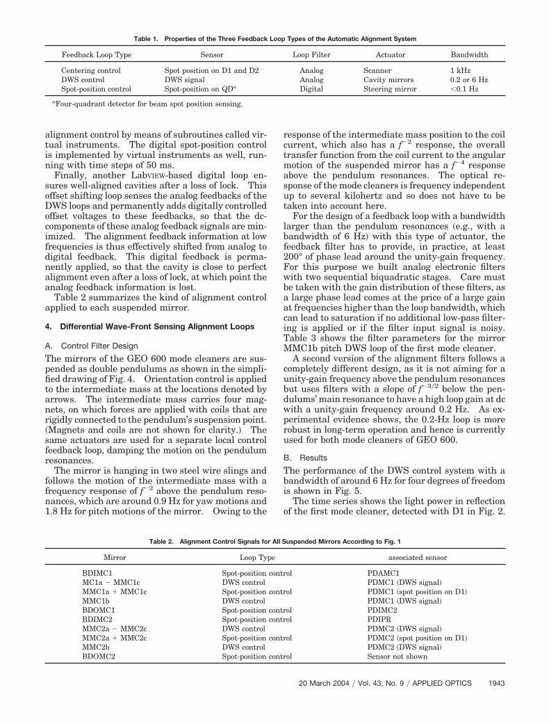
Table 1 summarizes some properties of the threeeedback loop types.
The analog electronic circuits of the DWS and cen-ering control loops are digitally supervised; the servoystems can be switched on and off, and loop gainsnd offsets can be adjusted from a computer controlystem based on LabVIEW.8 This computer controlystem guides the lock acquisition and automates the
atin
soDocifdnaa
a
4
A
Tpfitanr�sfr
ffn1
rctmasut
lbf2FwbaaciTM
cubdwpru
B
Tbi
o
lignment control by means of subroutines called vir-ual instruments. The digital spot-position controls implemented by virtual instruments as well, run-ing with time steps of 50 ms.Finally, another LabVIEW-based digital loop en-
ures well-aligned cavities after a loss of lock. Thisffset shifting loop senses the analog feedbacks of theWS loops and permanently adds digitally controlled
ffset voltages to these feedbacks, so that the dc-omponents of these analog feedback signals are min-mized. The alignment feedback information at lowrequencies is thus effectively shifted from analog toigital feedback. This digital feedback is perma-ently applied, so that the cavity is close to perfectlignment even after a loss of lock, at which point thenalog feedback information is lost.Table 2 summarizes the kind of alignment control
pplied to each suspended mirror.
. Differential Wave-Front Sensing Alignment Loops
. Control Filter Design
he mirrors of the GEO 600 mode cleaners are sus-ended as double pendulums as shown in the simpli-ed drawing of Fig. 4. Orientation control is appliedo the intermediate mass at the locations denoted byrrows. The intermediate mass carries four mag-ets, on which forces are applied with coils that areigidly connected to the pendulum’s suspension point.Magnets and coils are not shown for clarity.� Theame actuators are used for a separate local controleedback loop, damping the motion on the pendulumesonances.
The mirror is hanging in two steel wire slings andollows the motion of the intermediate mass with arequency response of f�2 above the pendulum reso-ances, which are around 0.9 Hz for yaw motions and.8 Hz for pitch motions of the mirror. Owing to the
Table 1. Properties of the Three Feedback
Feedback Loop Type Sensor
Centering control Spot position on D1 and D2DWS control DWS signalSpot-position control Spot-position on QDa
aFour-quadrant detector for beam spot position sensing.
Table 2. Alignment Control Signals fo
Mirror Loop Ty
BDIMC1 Spot-positionMC1a � MMC1c DWS controlMMC1a � MMC1c Spot-positionMMC1b DWS controlBDOMC1 Spot-positionBDIMC2 Spot-positionMMC2a � MMC2c DWS controlMMC2a � MMC2c Spot-positionMMC2b DWS controlBDOMC2 Spot-position
esponse of the intermediate mass position to the coilurrent, which also has a f�2 response, the overallransfer function from the coil current to the angularotion of the suspended mirror has a f�4 response
bove the pendulum resonances. The optical re-ponse of the mode cleaners is frequency independentp to several kilohertz and so does not have to beaken into account here.
For the design of a feedback loop with a bandwidtharger than the pendulum resonances �e.g., with aandwidth of 6 Hz� with this type of actuator, theeedback filter has to provide, in practice, at least00° of phase lead around the unity-gain frequency.or this purpose we built analog electronic filtersith two sequential biquadratic stages. Care muste taken with the gain distribution of these filters, aslarge phase lead comes at the price of a large gain
t frequencies higher than the loop bandwidth, whichan lead to saturation if no additional low-pass filter-ng is applied or if the filter input signal is noisy.able 3 shows the filter parameters for the mirrorMC1b pitch DWS loop of the first mode cleaner.A second version of the alignment filters follows a
ompletely different design, as it is not aiming for anity-gain frequency above the pendulum resonancesut uses filters with a slope of f�3�2 below the pen-ulums’ main resonance to have a high loop gain at dcith a unity-gain frequency around 0.2 Hz. As ex-erimental evidence shows, the 0.2-Hz loop is moreobust in long-term operation and hence is currentlysed for both mode cleaners of GEO 600.
. Results
he performance of the DWS control system with aandwidth of around 6 Hz for four degrees of freedoms shown in Fig. 5.
The time series shows the light power in reflectionf the first mode cleaner, detected with D1 in Fig. 2.
Types of the Automatic Alignment System
Loop Filter Actuator Bandwidth
Analog Scanner 1 kHzAnalog Cavity mirrors 0.2 or 6 HzDigital Steering mirror �0.1 Hz
uspended Mirrors According to Fig. 1
associated sensor
ol PDAMC1PDMC1 �DWS signal�
ol PDMC1 �spot position on D1�PDMC1 �DWS signal�
ol PDIMC2ol PDIPR
PDMC2 �DWS signal�ol PDMC2 �spot position on D1�
PDMC2 �DWS signal�ol Sensor not shown
Loop
r All S
pe
contr
contr
contrcontr
contr
contr
20 March 2004 � Vol. 43, No. 9 � APPLIED OPTICS 1943

Uocwtofsatm
aabspt
vma
dd
pmnlt
ofi6sm
s
Fnn
F6Awcpdi
Fpaaw
1
p to t 6s, the cavity is not in lock, and almost 100%f the incident light power is reflected. Then theavity is locked to an intentionally misaligned stateith only around 65% of the possible power entering
he cavity. At t 14s, the DWS control is switchedn for the two pitch degrees of freedom; at t 19s,eedback to the two yaw degrees of freedom iswitched on, and an optimal cavity alignment ischieved. The remaining reflected power level is dueo imperfect annular mode matching at the time thiseasurement was made.It can be seen that in this state the power fluctu-
tions are significantly smaller than in the mis-ligned case, owing to the minimized coupling ofeam geometry fluctuations. Finally, the graphhows the switching off in reverse order, with theendulums relaxing back to their equilibrium posi-ions. �The offset shifting loop was not engaged.�
Figure 6 shows the linear spectral density of theertical alignment fluctuations of mirror B of the firstode cleaner with alignment feedback �bandwidth is
round 6 Hz� switched off and on.This in-loop measurement shows a pitch noise re-
uction by the alignment system of approximately 20B at 1 Hz for the first mode cleaner. Note that this
Table 3. Filter Parameters for Mirror MMC1b
Degree of Freedom Zero Q Pole Q
MMC1b pitch 1.6 Hz 2 14 Hz 0.7
aEach entry represents a complex-conjugate pair, except for thpecified frequency.
ig. 4. Simplified double-pendulum suspension. The arrows de-ote locations where alignment forces are applied by coil and mag-et actuators �not shown�.
944 APPLIED OPTICS � Vol. 43, No. 9 � 20 March 2004
erformance is achieved with actuation only on theass above the mirror. Also shown is the sensoroise with no light detected; this is well below the
evel of residual alignment fluctuations with the au-omatic alignment switched on.
In addition, we demonstrated a stable long-termperation of an automatic alignment system for therst time. The system described for the two GEO00 mode cleaners has been in operation since thepring of 2001. No manual realignment of theode-cleaner mirrors has been required since then
h DWS Loop with a Bandwidth around 6 Hza
ero Q Pole Q Pole Q Integrator
Hz 1 20 Hz 1 40 Hz 2 0.8 Hz
t column, which denotes an integrator that is active below the
ig. 5. Time series of the light power reflected from the first GEO00 mode cleaner; the automatic alignment is switched on and off.t t 6s, the cavity is locked to an intentionally misaligned stateith only approximately 65% of the possible power entering the
avity. At t 14s, the DWS control is switched on for the twoitch degrees of freedom; at t 19s, feedback to the two yawegrees of freedom is switched on, and an optimal cavity alignments achieved. d.o.f., degree of freedom.
ig. 6. Spectral density of the DWS signals for mirror MMC1bitch with alignment feedback switched off and on. The peakround 2 Hz in the trace without alignment feedback is caused bysuspension mode. The dotted curve shows the sensors noiseith no light detected.
Pitc
Z
5
e las

�imliawA
5
Attollplwsrm
tosS
R1
2
3
4
5
6
7
8
except for a maintenance period in May 2002 thatncluded opening the vacuum system�. In contrast,
anual alignment corrections were necessary ateast every few days before the automatic system wasmplemented. The automatic alignment systemlso permits long stretches of continuous locking,ith more than 120 h achieved on a test-run period inugust 2002.
. Conclusion
n automatic alignment system, based on differen-ial wave-front sensing, has been implemented forhe two suspended, triangular mode-cleaner cavitiesf GEO 600, by use of three different types of controloop. The important new result of the system is itsong-term stability, allowing the mode cleaners to beermanently in use and remain aligned even afterosses of lock. The longest continuous lock achievedas more than 120 h. The authors believe that the
ystem is highly satisfactory for use in interferomet-ic gravitational wave detectors with which measure-ents are intended over long time periods.
The authors thank the Particle Physics and As-ronomy Research Council in the U.K., the Universityf Glasgow, the Bundesministerium fur Bildung, For-chung und Technologie, and the State of Loweraxony in Germany.
eferences. B. Willke, P. Aufmuth, C. Aulbert, S. Babak, R. Balasubrama-
nian, B. W. Barr, S. Berukoff, S. Bose, G. Cagnoli, M. M. Casey,D. Churches, D. Clubley, C. N. Colacino, D. R. M. Crooks, C.Cutler, K. Danzmann, R. Davies, R. Dupuis, E. Elliffe, C.Fallnich, A. Freise, S. Goßler, A. Grant, H. Grote, G. Heinzel, A.Heptonstall, M. Heurs, M. Hewitson, J. Hough, O. Jennrich, K.Kawabe, K. Kotter, V. Leonhardt, H. Luck, M. Malec, P. W.
McNamara, S. A. McIntosh, K. Mossavi, S. Mohanty, S.Mukherjee, S. Nagano, G. P. Newton, B. J. Owen, D. Palmer, M.A. Papa, M. V. Plissi, V. Quetschke, D. I. Robertson, N. A.Robertson, S. Rowan, A. Rudiger, B. S. Sathyaprakash, R.Schilling, B. F. Schutz, R. Senior, A. M. Sintes, K. D. Skeldon,P. Sneddon, F. Stief, K. A. Strain, I. Taylor, C. I. Torrie, A.Vecchio, H. Ward, U. Weiland, H. Welling, P. Williams, W.Winkler, G. Woan, and I. Zawischa, “The GEO 600 gravitationalwave detector,” Class. Quantum Grav. 19, 1377–1387 �2002�.
. E. Morrison, B. J. Meers, D. I. Robertson, and H. Ward, “Auto-matic alignment of optical interferometers,” Appl. Opt. 33,5041–5049 �1994�.
. E. Morrison, B. J. Meers, D. I. Robertson, and H Ward, “Exper-imental demonstration of an automatic alignment system foroptical interferometers,” Appl. Opt. 33, 5037–5040 �1994�.
. G. Heinzel, A. Rudiger, R. Schilling, K. Strain, W. Winkler, J.Mizuno, and K. Danzmann, “Automatic beam alignment in theGarching 30-m prototype of a laser-interferometric gravita-tional wave detector,” Opt. Commun. 160, 321–334 �1999�.
. R. W. P. Drever, J. L. Hall, F. V. Kowalski, J. Hough, G. M. Ford,A. J. Munley, and H. Ward, “Laser phase and frequency stabi-lization using an optical resonator,” Appl. Phys. B 31, 97–105�1983�.
. G Heinzel, “Advanced optical techniques for laser-interferometric gravitational-wave detectors,” Ph.D. thesis�University of Hannover, Hannover, Germany, 1999�. Alsoavailable as MPQ Report 243 �Max-Planck-Institut fur Quan-tenoptik, Garching, Germany, 1999� pp. 141–146.
. S. Goßler, M. M. Casey, A. Freise, A. Grant, H. Grote, G. Heim-zel, M. Heurs, M. E. Husman, K. Kotter, V. Leonhardt, H. Luck,M. Malec, K. Mossavi, S. Nagano, P. W. McNamara, M. V. Plissi,V. Quetschke, D. I. Robertson, N. A. Robertson, A. Rudiger, R.Schilling, K. D. Skeldon, K. A. Strain, C. I. Torrie, H. Ward, U.Weiland, B. Willke, W. Winkler, J. Hough, and K. Danzmann,“Mode-cleaning and injection optics of the gravitational-wavedetector GEO 600,” Rev. Sci. Instrum. 74, 3787–3795 �2003�.
. M. M. Casey, H. Ward, and D. I. Robertson, “Computer moni-toring and control of the GEO 600 gravitational wave detector,”Rev. Sci. Instrum. 71, 3910–3917 �2000�.
20 March 2004 � Vol. 43, No. 9 � APPLIED OPTICS 1945