ATV71_Setting awal Indonesia.pdf - Explore Exchange ...
76
ATV 61&71 Training Workshops Motion & Drives Training Arifin Indra Harnanto 08119208633 [email protected]
-
Upload
khangminh22 -
Category
Documents
-
view
2 -
download
0
Transcript of ATV71_Setting awal Indonesia.pdf - Explore Exchange ...

2Schneider Electric- Drives Training - Arifin Indra 2014Summary
Diagram
M3 ~
� 230V
Altivar 71
R4A
R4C
LO3
CLO⊗
⊗
L1 L2 L3
U V W
24V230V~
0VP24
- +
AO4-20mA
AI1+
AI2
AI4
0-10V
4-20mA
0-10V
Linecontactor
Dowstreamcontactor
Encoder
1024
10 LI + PWR
First of all
Have a look to the diagram of the demo case,
• Identify I/O wiring,
• Note the motor name plate .

3Schneider Electric- Drives Training - Arifin Indra 2014Summary
Graphic keypad basics
- - F Fault (see the manual for details on fault codes)
(Drive desabled)

4Schneider Electric- Drives Training - Arifin Indra 2014Summary
Graphic keypad basics

Shortcut
Run (local)
Stop (local)
Forward/Reverse (local)
Enter
Escape
Status Inverter
Mode commandMonitoring value : - Frequency reference- Motor current- Motor torque- Etc
Human Machine InterfaceGraphic Terminal / Keypad

6Schneider Electric- Drives Training - Arifin Indra 2014Summary
Using the Jog Dial
ENT Increase/Decrease andvalidation

7Schneider Electric- Drives Training - Arifin Indra 2014Summary
Menu map

8Schneider Electric- Drives Training - Arifin Indra 2014Summary
Initialization FACTORY SETTING
● In Main menu● Set Language English● Set Access Level Advanced
● In Drive Menu● Go to Factory setting● Do a factory setting of all parameters

9Schneider Electric- Drives Training - Arifin Indra 2014Summary
Check I/O wiring and level
● From the button box set the Power Removal switch to off● This will show PRA in the top left● The drive cannot run while in this state.
● Change I/O state to check if its seen by the drive● Select and push enter to see its actual assignment and scaling

10Schneider Electric- Drives Training - Arifin Indra 2014Summary
Set Basic drive parameters
● Start up with Simply Start● Select “ 2 or 3 wires control ”
Start the motor make a test in 2 wire mode then in 3 wire mode
See programming manual page 41
1.1 SIMPLY START
2/3 wire controlMacro configurationStandard mot. freqInput phase lossRated motor powerRated motor voltRated motor currentRated motor freqRated motor speedMax frequencyAuto tuningAuto tuning statusOutput phase rotationMotor therm. currentAccelerationDecelerationLow speedhigh speed
1 DRIVE MENU
1.1 SIMPLY START1.2 MONITORING1.3 SETTINGS1.4 MOTOR CONTROL1.5 INPUTS / OUTPUTS CFG1.6 COMMAND1.7 APPLICATION FUNCT.1.8 FAULT MANAGEMENT1.9 COMMUNICATION1.10 DIAGNOSTICS1.11 IDENTIFICATION1.12 FACTORY SETTINGS1.13 USER MENU1.14 PROGRAMABLE CARD
MAIN MENU
1 DRIVE MENU2 ACCESS LEVEL3 OPEN / SAVE AS4 PASSWORD5 LANGUAGE6 MONITORING CONFIG7 DISPLAY CONFIG

11Schneider Electric- Drives Training - Arifin Indra 2014Summary
Set Basic drive parameters
● Start up with Simply Start● Select the macro configuration “ Start/Stop ” (push 3 seconds to validate)
See programming manual page 38
1.1 SIMPLY START
2/3 wire controlMacro configurationStandard mot. freqInput phase lossRated motor powerRated motor voltRated motor currentRated motor freqRated motor speedMax frequencyAuto tuningAuto tuning statusOutput phase rotationMotor therm. currentAccelerationDecelerationLow speedhigh speed
1 DRIVE MENU
1.1 SIMPLY START1.2 MONITORING1.3 SETTINGS1.4 MOTOR CONTROL1.5 INPUTS / OUTPUTS CFG1.6 COMMAND1.7 APPLICATION FUNCT.1.8 FAULT MANAGEMENT1.9 COMMUNICATION1.10 DIAGNOSTICS1.11 IDENTIFICATION1.12 FACTORY SETTINGS1.13 USER MENU1.14 PROGRAMABLE CARD
MAIN MENU
1 DRIVE MENU2 ACCESS LEVEL3 OPEN / SAVE AS4 PASSWORD5 LANGUAGE6 MONITORING CONFIG7 DISPLAY CONFIG

12Schneider Electric- Drives Training - Arifin Indra 2014Summary
Set Basic drive parameters
● Start up with Simply Start
See programming manual page 38
1.1 SIMPLY START
2/3 wire controlMacro configurationStandard mot. freqInput phase lossRated motor powerRated motor voltRated motor currentRated motor freqRated motor speedMax frequencyAuto tuningAuto tuning statusOutput phase rotationMotor therm. currentAccelerationDecelerationLow speedhigh speed
1 DRIVE MENU
1.1 SIMPLY START1.2 MONITORING1.3 SETTINGS1.4 MOTOR CONTROL1.5 INPUTS / OUTPUTS CFG1.6 COMMAND1.7 APPLICATION FUNCT.1.8 FAULT MANAGEMENT1.9 COMMUNICATION1.10 DIAGNOSTICS1.11 IDENTIFICATION1.12 FACTORY SETTINGS1.13 USER MENU1.14 PROGRAMABLE CARD
MAIN MENU
1 DRIVE MENU2 ACCESS LEVEL3 OPEN / SAVE AS4 PASSWORD5 LANGUAGE6 MONITORING CONFIG7 DISPLAY CONFIG Allows to preset the motor name plate for an IEC motor
(European type 50Hz) or a NEMA motor (US type 60Hz)

13Schneider Electric- Drives Training - Arifin Indra 2014Summary
Set Basic drive parameters
● Start up with Simply Start
1.1 SIMPLY START
2/3 wire controlMacro configurationStandard mot. freqInput phase lossRated motor powerRated motor voltRated motor currentRated motor freqRated motor speedMax frequencyAuto tuningAuto tuning statusOutput phase rotationMotor therm. currentAccelerationDecelerationLow speedhigh speed
1 DRIVE MENU
1.1 SIMPLY START1.2 MONITORING1.3 SETTINGS1.4 MOTOR CONTROL1.5 INPUTS / OUTPUTS CFG1.6 COMMAND1.7 APPLICATION FUNCT.1.8 FAULT MANAGEMENT1.9 COMMUNICATION1.10 DIAGNOSTICS1.11 IDENTIFICATION1.12 FACTORY SETTINGS1.13 USER MENU1.14 PROGRAMABLE CARD
MAIN MENU
1 DRIVE MENU2 ACCESS LEVEL3 OPEN / SAVE AS4 PASSWORD5 LANGUAGE6 MONITORING CONFIG7 DISPLAY CONFIG
Max frequency (TFR) = max value possible for high speed (HSP)
High Speed (HSP) = max value for freq set point (reference)
Low Speed (LSP) = min value for freq set point (reference)
Rated motor freq (FRS) = motor rated frequency
Allowable frequency set point range
Frequency reference

14Schneider Electric- Drives Training - Arifin Indra 2014Summary
Set Basic drive parameters
● Start up with Simply Start● In Drive Menu Go to Simply start
1.1 SIMPLY START
2/3 wire controlMacro configurationStandard mot. freqInput phase lossRated motor powerRated motor voltRated motor currentRated motor freqRated motor speedMax frequencyAuto tuningAuto tuning statusOutput phase rotationMotor therm. currentAccelerationDecelerationLow speedhigh speed
1 DRIVE MENU
1.1 SIMPLY START1.2 MONITORING1.3 SETTINGS1.4 MOTOR CONTROL1.5 INPUTS / OUTPUTS CFG1.6 COMMAND1.7 APPLICATION FUNCT.1.8 FAULT MANAGEMENT1.9 COMMUNICATION1.10 DIAGNOSTICS1.11 IDENTIFICATION1.12 FACTORY SETTINGS1.13 USER MENU1.14 PROGRAMABLE CARD
MAIN MENU
1 DRIVE MENU2 ACCESS LEVEL3 OPEN / SAVE AS4 PASSWORD5 LANGUAGE6 MONITORING CONFIG7 DISPLAY CONFIG
Rated motor freq (FRS) = motor rated frequency
Output Frequency
ACC (s) DEC (s)
Acceleration (ramp time) = time to go from 0 to FRS
Deceleration (ramp time) = time to go from FRS to 0
Time

15Schneider Electric- Drives Training - Arifin Indra 2014Summary
Set Basic drive parameters
● Start up with Simply Start● Enter the motor name plate● Make the “ Auto-tuning ”
1.1 SIMPLY START
2/3 wire controlMacro configurationStandard mot. freqInput phase lossRated motor powerRated motor voltRated motor currentRated motor freqRated motor speedMax frequencyAuto tuningAuto tuning statusOutput phase rotationMotor therm. currentAccelerationDecelerationLow speedhigh speed
1 DRIVE MENU
1.1 SIMPLY START1.2 MONITORING1.3 SETTINGS1.4 MOTOR CONTROL1.5 INPUTS / OUTPUTS CFG1.6 COMMAND1.7 APPLICATION FUNCT.1.8 FAULT MANAGEMENT1.9 COMMUNICATION1.10 DIAGNOSTICS1.11 IDENTIFICATION1.12 FACTORY SETTINGS1.13 USER MENU1.14 PROGRAMABLE CARD
MAIN MENU
1 DRIVE MENU2 ACCESS LEVEL3 OPEN / SAVE AS4 PASSWORD5 LANGUAGE6 MONITORING CONFIG7 DISPLAY CONFIG
Auto tuning
NoYesDone
During auto tune the rated current is send to the motor for a short time to measure the stator drop voltage and the leakage inductance
The motor doesn’t turn

16Schneider Electric- Drives Training - Arifin Indra 2014Summary
Set Basic drive parameters
● Start up with Simply Start● Adjust Motor thermal current to the motor rated
current
1.1 SIMPLY START
2/3 wire controlMacro configurationStandard mot. freqInput phase lossRated motor powerRated motor voltRated motor currentRated motor freqRated motor speedMax frequencyAuto tuningAuto tuning statusOutput phase rotationMotor therm. currentAccelerationDecelerationLow speedhigh speed
1 DRIVE MENU
1.1 SIMPLY START1.2 MONITORING1.3 SETTINGS1.4 MOTOR CONTROL1.5 INPUTS / OUTPUTS CFG1.6 COMMAND1.7 APPLICATION FUNCT.1.8 FAULT MANAGEMENT1.9 COMMUNICATION1.10 DIAGNOSTICS1.11 IDENTIFICATION1.12 FACTORY SETTINGS1.13 USER MENU1.14 PROGRAMABLE CARD
MAIN MENU
1 DRIVE MENU2 ACCESS LEVEL3 OPEN / SAVE AS4 PASSWORD5 LANGUAGE6 MONITORING CONFIG7 DISPLAY CONFIG
The motor therm. current is use to adjust the thermal overload protectionof the motor. In most of the cases ithas to be set to the motor rated current
The standard curves used are scaled for a class 10 motor

17Schneider Electric- Drives Training - Arifin Indra 2014Summary
Monitoring display● On the main display show as bargraph values :
● "Output frequency“● “Motor Current”
● Display on the keypad top bar the :● “Motor Speed” ● “Motor Voltage”

18Schneider Electric- Drives Training - Arifin Indra 2014Summary
Save/recall configuration with the GD

19Schneider Electric- Drives Training - Arifin Indra 2014Summary
Save/recall configuration into the ATV
1 DRIVE MENU
1.1 SIMPLY START1.2 MONITORING1.3 SETTINGS1.4 MOTOR CONTROL1.5 INPUTS / OUTPUTS CFG1.6 COMMAND1.7 APPLICATION FUNCT.1.8 FAULT MANAGEMENT1.9 COMMUNICATION1.10 DIAGNOSTICS1.11 IDENTIFICATION1.12 FACTORY SETTINGS1.13 USER MENU1.14 PROGRAMABLE CARD
MAIN MENU
1 DRIVE MENU2 ACCESS LEVEL3 OPEN / SAVE AS4 PASSWORD5 LANGUAGE6 MONITORING CONFIG7 DISPLAY CONFIG
1.12 FACTORY SETTINGS
Config. SourcePARAMETER GROUP LISTGoto FACTORY SETTINGSSave Config
PARAMETER GROUP LIST
ALLDrive menuSettingsMotpr paramComm. MenuProg. card menuDisplay config
1.12 FACTORY SETTINGS
Config. SourcePARAMETER GROUP LISTGoto FACTORY SETTINGSSave Config
GOTO FACTORY SETPLEASE CHECK THATTHE DRIVE WIRING IS OKESC to abortENT to continue
Config. Source
Macro Conf.Conf1Conf2
Save Config. Conf1Conf2
1.12 FACTORY SETTINGS
Config. SourcePARAMETER GROUP LISTGoto FACTORY SETTINGSSave Config
1.12 FACTORY SETTINGS
Config. SourcePARAMETER GROUP LISTGoto FACTORY SETTINGSSave Config
ESCENT
ENT
3 sec
Save in conf1
Recall from conf1

20Schneider Electric- Drives Training - Arifin Indra 2014Summary
Set a relay● Set the relay R2 to Open the brake while the drive is running ● The brake should close 1s after the stop command
1 DRIVE MENU
1.1 SIMPLY START1.2 MONITORING1.3 SETTINGS1.4 MOTOR CONTROL1.5 INPUTS / OUTPUTS CFG1.6 COMMAND1.7 APPLICATION FUNCT.1.8 FAULT MANAGEMENT1.9 COMMUNICATION1.10 DIAGNOSTICS1.11 IDENTIFICATION1.12 FACTORY SETTINGS1.13 USER MENU1.14 PROGRAMABLE CARD
MAIN MENU
1 DRIVE MENU2 ACCESS LEVEL3 OPEN / SAVE AS4 PASSWORD5 LANGUAGE6 MONITORING CONFIG7 DISPLAY CONFIG
R2
1.5 INPUTS / OUTPUTS CFG
2/3 wire control2 wire typeReverse assign.LI1 CONFIGURATIONLI2 CONFIGURATIONLI3 CONFIGURATIONLI4 CONFIGURATIONLI5 CONFIGURATIONLI6 CONFIGURATIONReference templateAI1 CONFIGURATIONAI2 CONFIGURATIONR1 CONFIGURATIONR2 CONFIGURATIONAO1 CONFIGURATIONALARM GRP1 DEFINITIONALARM GRP2 DEFINITIONALARM GRP3 DEFINITION
R2 CONFIGURATION
R2 Assignment : Drv runningR2 Delay timeR2 Active at : 1R2 Holding Time 1000

21Schneider Electric- Drives Training - Arifin Indra 2014Summary
Change the control place HMI/Terminal● Change the control place (command and reference) f rom button box
(terminals) to the Graphic keypad (HMI) with a logi c input (LI5)
1 DRIVE MENU
1.1 SIMPLY START1.2 MONITORING1.3 SETTINGS1.4 MOTOR CONTROL1.5 INPUTS / OUTPUTS CFG1.6 COMMAND1.7 APPLICATION FUNCT.1.8 FAULT MANAGEMENT1.9 COMMUNICATION1.10 DIAGNOSTICS1.11 IDENTIFICATION1.12 FACTORY SETTINGS1.13 USER MENU1.14 PROGRAMABLE CARD
MAIN MENU
1 DRIVE MENU2 ACCESS LEVEL3 OPEN / SAVE AS4 PASSWORD5 LANGUAGE6 MONITORING CONFIG7 DISPLAY CONFIG
Ref 1 Channel = AI1
Ref 2 Channel = HMI
1.6 COMMAND
Ref.1 channel AI1RV InhibitionStop Key priorityProfileCmd switchingCmd channel 1Cmd channel 2Ref. 2 switching LI5Ref. 2 channel HMICopy channel 1 to 2F1 key assignmentF2 key assignmentF3 key assignmentF4 key assignment
LI5

22Schneider Electric- Drives Training - Arifin Indra 2014Summary
Simple Trouble shooting● Start the motor, then disconnect one of the motor c onnection jumper● Use the diagnostic menu to have more info about the fault F1 (Help)● Use the Fault menu to assign LI6 to reset fault
1 DRIVE MENU
1.1 SIMPLY START1.2 MONITORING1.3 SETTINGS1.4 MOTOR CONTROL1.5 INPUTS / OUTPUTS CFG1.6 COMMAND1.7 APPLICATION FUNCT.1.8 FAULT MANAGEMENT1.9 COMMUNICATION1.10 DIAGNOSTICS1.11 IDENTIFICATION1.12 FACTORY SETTINGS1.13 USER MENU1.14 PROGRAMABLE CARD
MAIN MENU
1 DRIVE MENU2 ACCESS LEVEL3 OPEN / SAVE AS4 PASSWORD5 LANGUAGE6 MONITORING CONFIG7 DISPLAY CONFIG
1.10 DIAGNOSTICS
FAULT HISTORYCURRENT FAULT LISTMORE FAULT INFOTEST PROCEDURESService Message
1 DRIVE MENU
1.1 SIMPLY START1.2 MONITORING1.3 SETTINGS1.4 MOTOR CONTROL1.5 INPUTS / OUTPUTS CFG1.6 COMMAND1.7 APPLICATION FUNCT.1.8 FAULT MANAGEMENT1.9 COMMUNICATION1.10 DIAGNOSTICS1.11 IDENTIFICATION1.12 FACTORY SETTINGS1.13 USER MENU1.14 PROGRAMABLE CARD
1.8 FAULT MANAGEMENT
PTC MANAGEMENTFAULT RESETAUTOMATIC RESTARTCATCH ON THE FLYMOTOR THERMAL PROT.OUTPUTPHASE LOSSINPUT PHASE LOSSDRIVE OVERHEAT…..
FAULT RESET
NoLI1..LI6LIn…..

Before entering an access code , the registration a nd load rights of the configuration must have been defined, either with the graphic display terminal or with Powersuit e when the code is active.
Choice of the code types :PIN1 can be cancelled by 6969 codePIN2 (expert) can be cancelled ONLY by =S= services
The codes have the same function, they lock :• List of protected channels and parameters *• Return to factory settings.• User menu• Customisation of the terminal and its display
• Password

Language
● The graphic display terminal can hold up to 6 langu ages in standard : English, French, Deutsche, Spanish, Italian, Chines e.
● A simple procedure allows you replace one language with another
● It is possible to display Chinese, Japanese and Cyr illic characters

Monitoring Screen
Customisation of the display
Central display (6 lines) :● Select type of values TO display
● Digital values
● Bar graph ● List
● Select parameter(s) to display
Top status bar ● Select 2 parameters to display
Digital value (2 max)
Bar graph (2 max)
Value list (5 max)
Digital value (2 max)

27Schneider Electric- Drives Training - Arifin Indra 2014Summary
Wiring Configuration

28Schneider Electric- Drives Training - Arifin Indra 2014Summary
Terminal Wiring

29Schneider Electric- Drives Training - Arifin Indra 2014Summary
Important setting
1. Data motor must be complete
After data motor
complete…Do an
autotune!!!

30Schneider Electric- Drives Training - Arifin Indra 2014Summary
Application Function Compatibility
Ope
ratio
n on
ref
eren
ces
+ /
- S
peed
Man
agem
ent o
f lim
itsw
itche
s
Pre
set s
peed
s
PID
reg
ulat
or
Tra
vers
e co
ntro
l
JOG
ope
ratio
n
Bra
ke c
ontr
ol
Cat
ch o
n th
e fly
Dow
nstr
eam
con
tact
or
DC
inje
ctio
n st
op
Fas
t sto
p
Fre
e w
heel
sto
p
+ /
- S
peed
aro
und
are
fere
nce
Hig
h-sp
eed
liftin
g
Tor
que
cont
rol
Load
bal
anci
ng
Pos
ition
ing
on li
mit
switc
hes
Operation on references ↑ • ↑ •+ / - Speed • • •Management of limit switches •Preset speeds ← ↑ •PID regulator • • • • • • • • • •Traverse control • • • • •JOG operation ← • ← • • • • • •Brake control • • • • •Catch on the fly • •Downstream contactor •DC injection stop • • ↑Fast stop • ↑Free wheel stop ← ←+ / - Speed around a reference • • • •High-speed lifting • • • • •Torque control • • • • • • • • • • • •Load balancing • •Positioning on limit switches • • •
Incompatible only whentorque control is activatedPriority to the first activated modeExcept special use with Fr2
• Incompatible functions
↑ The arrow shows the priority

31Schneider Electric- Drives Training - Arifin Indra 2014Summary
Access Level

32Schneider Electric- Drives Training - Arifin Indra 2014Summary
Workshop Basic
1. Change the motor rotation 2. Display monitoring to see ampere, rpm, motor power, main voltage, freq reference3. Make LI2 to Reverse4. Try 2 wire and 3 wire type5. Make R1, no Drive Fault and R2 Drive Run6. Set up F4 to T/K

33Schneider Electric- Drives Training - Arifin Indra 2014Summary
The start and stop operation have to be soft for th at we will use 2 different ramp slopes in order to limit the jerk at starting and stopping.
The motor has to accelerate in 5s from 0 to 10hzThe in 10s from 10hz to 50Hz and the same for deceler ation
Conveyor with smooth start
5s 10s
10hz
HSP
0
Use Menu :
Setting Application functions (ramp )Motor frequency
Time
Second ramp trig point
ACCAC2 DE2
DEC

34Schneider Electric- Drives Training - Arifin Indra 2014Summary
Sistem digunakan untuk selektor Speed Low, Medium, Dan High
Conveyor with preset speeds
Start Fw LI1Start Rv LI2
Conveyor speed mode Manual-Slow-Medium-High
LI4 – LI5
LI4 LI5 LI6 Mode ConvSpeed
0 0 0 Manual Pot AI1 + AI4
1 0 0 Slow 20hz
0 1 0 Medium 40Hz
0 0 1 High 50Hz
Use Menu :
Application functions (Preset Speeds )
0-10v
Main Line speed
AI1

35Schneider Electric- Drives Training - Arifin Indra 2014Summary
Conveyor with preset speedsCara SettingGoto Drive Menu � Application Function � Preset Speed

JOG FunctionMenu FUn- JOG-
● JOG function● LI assignment parameter : JOG● Jog frequency : JGF
● Value from 0 to 10 Hz● Factory setting : 10 Hz
Check compatibility

JOG Function
Check compatibility
Cara SettingGoto Drive Menu � Application Function � Jog Function

38Schneider Electric- Drives Training - Arifin Indra 2014Summary
�The speed set point can come also from a PLC, when LI6 is activated then only the speed set point is set by the PLC – The Start-Stop command sti ll on the button box
Conveyor with manual or auto control
Use Menu :
Command
I-O
Modbus
Remote conveyor speed by PLC
Remote/local
Speed ref
LI6
Local Conveyor speed

39Schneider Electric- Drives Training - Arifin Indra 2014Summary
�Saat selector LI6 on, maka konveyor digerakkan secara au to (dari PLC via modbus)
Conveyor with manual or auto control
Cara Setting Access ExpertGoto Drive Menu � Command

+ / - SpeedNaik turun kecepatan dengan tombolMenu FUn- UPd-
● Allows progressive increase or decrease of speed [+/- SPEED]
● function accessible in level LAC = L2 or L3
● Also available in menu CtL- (Fr1 and Fr2)
● Control modes
● by terminal with LI (Updt) with simple or double action button.
● LI assigned by parameters USP [+ speed assignment] and dSP [-
speed assignment]
● by standard or remote keypad (UpdH) with action on t and u keys
● Specifications
● max speed given by HSP
● terminal command incompatible with 3 wire control
● reference memorization possible with parameter Str [Reference
saved]
● nO : no memory (factory setting)
● rAM : memory in RAM
● EEP : memory in EEPROM
Check compatibility

+ / - SpeedMenu FUn- UPd-

+ / - SpeedCara Setting Access ExpertGoto Drive Menu � Command & Application Function
+ / - Speed around referenceMenu FUn- UPd-

44Schneider Electric- Drives Training - Arifin Indra 2014Summary
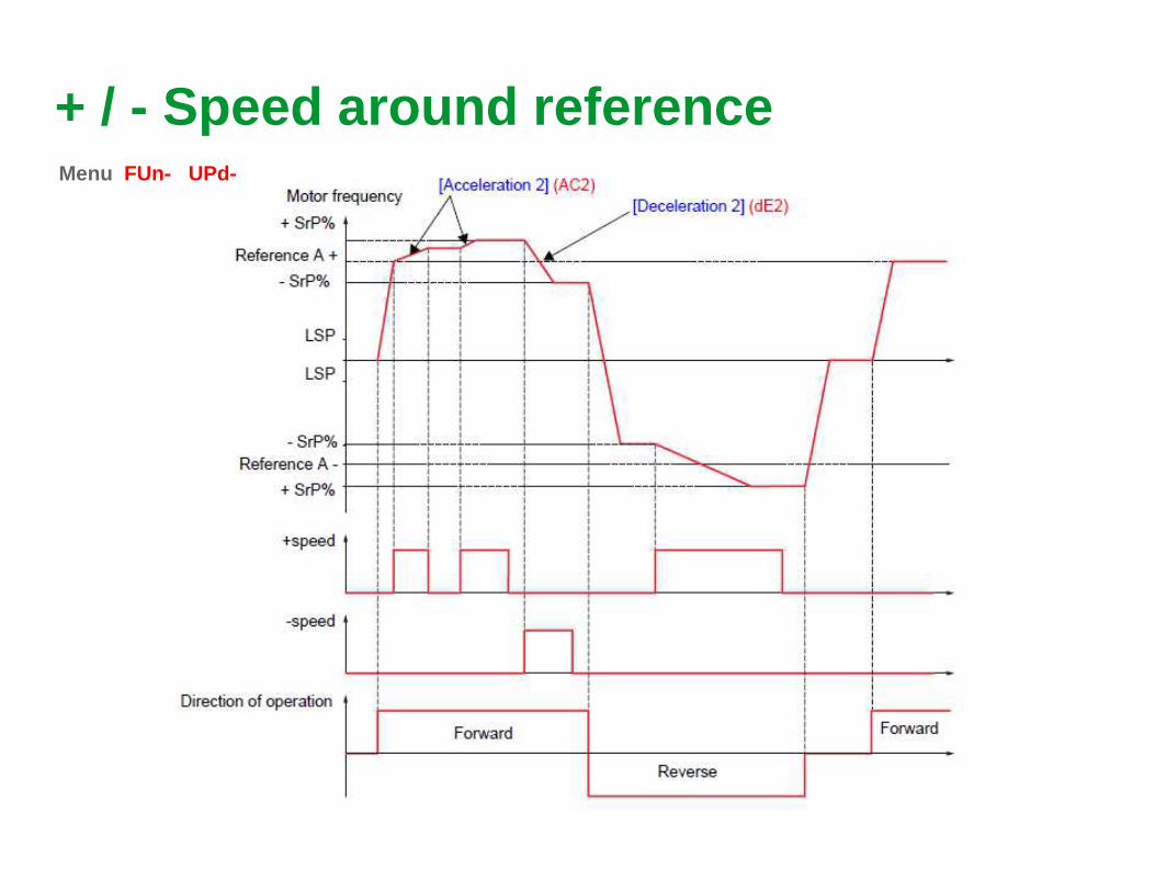
Limit Switch Management
45Schneider Electric- Drives Training - Arifin Indra 2014Summary
Limit Switch ManagementCara Setting Access ExpertGoto Drive Menu � Command & Application Function
Fungsi ini biasanya digunakan untuk apikasi traveling crane, Fungsi ini motor akan langsung stop saat limit switch energize

46Schneider Electric- Drives Training - Arifin Indra 2014Summary
Positioning By Sensor
● 4 sensors are assigned to the logic inputs in the p rogram
● 2 logic inputs are assigned to forward and reverse
● The movement speed between the slow down sensors is given by the active reference
● Speed switches to the low speed reference LSP when a slow down sensor is reached
● The stop can be programmed :● to a ramp● rapid stop
● free wheel stop, or even use Brake logic control.
● An input assigned to CLS allows the deactivation at the end of the programme d movement (pass through).

47Schneider Electric- Drives Training - Arifin Indra 2014Summary
Positioning By SensorCara Setting Access ExpertGoto Drive Menu � Command & Application Function
Fungsi ini biasanya digunakan untuk apikasi traveling crane, Motor akan slow speed saat terkena switch pertama, dan stop saat switch kedua

48Schneider Electric- Drives Training - Arifin Indra 2014Summary
Multi motors – Multi configurations ● Switching in Multi motors mode
● The switch can be made only if the drive is disable d● The thermal state of each motor is saved and update d.● Manual auto-tuning or at each first application of voltage to each motor
Con
fig. 0
Con
fig.1
Con
fig..2
Lix =
CNF1
Liy =
CNF2
Rx= CONF0 Rz= CONF2Ry= CONF1
Logic inputs (Li) Logic ouputs (R, do)
CNF1 CNF2 CONF0 CONF1 CONF2
Motor 1 0 0 1 0 0
Motor 2 1 0 0 1 0
Motor 3 X 1 0 0 1
Confn = Menus confn + TUNn + motor thermal state n
LI CNF1
Config 0 Config 1
RUN
Motor 1 Motor 2

49Schneider Electric- Drives Training - Arifin Indra 2014Summary
Multi motors – Multi configurations
EEPROM
RAM
Factorysetting
ROM
Multi motors –Multi configurations
(LI)
Par1
Par2
Par3
ActiveCONF
Parameter switching (LI)
Powersuite
Graphicterminal
Parameter modifications
Save as open
Files 1 à 4
Par1
Par2
Par3
CONF 0
Par1
Par2
Par3
CONF 1
Par1
Par2
Par3
CONF 2
Com
mun
icat
ion
/ Dis
play
con
fig. /
Sco
pe

50Schneider Electric- Drives Training - Arifin Indra 2014Summary
PID Regulator - Description
PIFPID Feedback
PIFPIP
Scaling
FPIPredictive reference
PSR
Ramp
ACCDEC
Scaling
PIMManual
Reference
Auto/manu
PAU
Alarm • error ( PEE)• feedback ( PFA)
PIDReference Ramp
PRP
+
-
Inversion
PIC
Wake-up level
TLSRSL
PID Regulator
RPG RIG RDGS POH POL
+
+
Integral Shunt
PIS
Display • output ( OPI)• feedback ( OPF)• error( OPE)• reference ( OPS)

51Schneider Electric- Drives Training - Arifin Indra 2014Summary
PID Regulator – Predictive reference• The speed input allows to send directly a speed ref erence on the output of the PID
regulator.• It is sent through the ramps ACC/DEC an can be adju sted with a coefficient (PSR)• It can be used for example, to bring up a process s moothly to a certain speed and then
only apply the PID reference.
ACC
Reference on the speed input
FPI
PID reference
PID output frequency
DEC
Process regulation speed range
Run

52Schneider Electric- Drives Training - Arifin Indra 2014Summary
PID Regulator – Wake-up function● If automatic stop at low speed is programmed ( TLS) with the PI regulator, this function
allows the reactivation of regulation once a progra mmable error level is passed ( RSL).
PID output Frequency
t
PID Error %
t
LSP
At low speed LSPafter the time TLSthe output frequency of the regulator is forced to 0
TLSTLS min time at LSP
RSL
RSL level of PI error to reactivate the output of the PI regulator

53Schneider Electric- Drives Training - Arifin Indra 2014Summary
PID Regulator Workshop ATV61/71
1. Sensor yang digunakan adalah pressure transmitter 0-10 Bar, 4-20mA2. Sistem menginginkan jalan di 6 Bar3. Setelah bar tercapai, selama 10 detik motor akan berhenti4. Motor akan nyala secara otomatis saat Bar turun dibawah 5 Bar
Jika nilai pressure ingin dirubah maka yang dirubah adalah InternalPI Reference

54Schneider Electric- Drives Training - Arifin Indra 2014Summary
PID ATV 312
1. Sensor yang digunakan adalah pressure transmitter 0-10 Bar, 4-20mA2. Sistem menginginkan jalan di 6 Bar3. Setelah bar tercapai, selama 10 detik motor akan berhenti4. Motor akan nyala secara otomatis saat Bar turun dibawah 5 Bar
Jika nilai pressure ingin dirubah maka yang dirubah adalah InternalPI Reference

55Schneider Electric- Drives Training - Arifin Indra 2014Summary
PID ATV 212 WIRING

56Schneider Electric- Drives Training - Arifin Indra 2014Summary
PID ATV 212 Setting
1. Sensor yang digunakan adalah pressure transmitter 0-10 Bar, 4-20mA2. Sistem menginginkan jalan di 6 Bar3. Setelah bar tercapai, selama 10 detik motor akan berhenti4. Motor akan nyala secara otomatis saat Bar turun dibawah 5 Bar
Untuk mendapatkan 6 bar, berarti potensio referensi kita buat 6 v

58Schneider Electric- Drives Training - Arifin Indra 2014Summary
Speed loop with the democase
● Do a factory setting of the ATV71● Do the simplest commissioning● Test quickly the good control of the motor by the A TV71
● Targeted application: Material-Handling● What kind of constraints and performances have to b e taken into account?● How to set the speed loop ?● What are the efficient gains and filters ?● With PowerSuite, display the results with the oscil loscope tool.● Create voluntary instabilities and explain.● Find the best adjustments – Compare the open loop an d the closed loop● Now, in case of an Hoisting application will you need to reach the same kind of performance s?
Why?

59Schneider Electric- Drives Training - Arifin Indra 2014Summary
● From factory settings.● Start up with “Simply Start”
● Select macro configuration “Start/Stop”● Enter the motor name plate (0.18kW, 230V, 50Hz, 1A, 1385 Rpm)● Don’t make the autotun at the moment
● Then start the motor at low speed 1-2Hz● To test the torque at low speed, carefully and prog ressively push your thumb on the motor disk (inerti a),
could you stop it easily ?● Stop then make the auto tune, then do the previous operation● What are your conclusion ?
● Then decrease the parameter UFR (IR compensation) t o 20%● Test the torque as before, What are your conclusion ?● Increase UFR progressively above 100% what’s happen ?
● Switch the motor control law to U/F● Do the same as before ● What are you conclusion ?● Increase U0 trying to improve
● Test the encoder● Then switch the motor control law to FVC● Do the same as before ● What are you conclusion ?
Motor control

60Schneider Electric- Drives Training - Arifin Indra 2014Summary
Speed loop setting
● Return to SVCU motor control law● For this ws use Powersuite oscilloscope function
● Put ACC and DEC to 0.2s● Configure Powersuite Oscilloscope
● Display Speed reference after ramp (FRO)● Measured frequency (SRFR or SMMF)● Trig on FRO (0.1hz) put a delay (200mS)● Start with full speed (HSP)● Make a record with actual gain setting, what do you remark ?, how to improve ?● First act on the proportional gain (SPG) step by ste p
● Decrease the value first , what’s happen ?● Then increase it what’s happen?
● With your best SPG value then act on the integral t ime gain (SIT) step by step● Decrease the value first , what’s happen ?● Then increase it what’s happen?
● Make the test with different motor control law U/F, SVCU, SVCI, FVC● What are you conclusions ?

61Schneider Electric- Drives Training - Arifin Indra 2014Summary
IR Compensation● Adjustment if IR compensation (UFR) :
● UFR adjusts the compensation for the stator voltage drop (RsI)● It permits :
● Improvement of the speed estimation● Optimization of static performance at low speed
● Optimization of dynamic performance● Optimization of following a dynamic ramp
● Improvement of stopping at “ zero ” speed● UFR 100%= Rs nominal (tun, tabulated or calculated)
U stator
F statorUFR
UFR is set automatically as a function of current
The factory setting works in most cases
An overestimation can saturate the motor

62Schneider Electric- Drives Training - Arifin Indra 2014Summary
Speed loop settingsReaction to a speed set point impulse
time
Frequency
Set point
2 gains allows optimization of the system response :
SPG (kp) Speed Proportional gain
SIT (1/ki) Speed Integral time (reverse of Ki)

63Schneider Electric- Drives Training - Arifin Indra 2014Summary
PI speed feedback loop
● Speed loop structure
Speed Ramp
Speedreference
Speed feedback
+
-
Regulator
Torque current
referenceLimitation
SPG SIT=1/gI
Filter
SFCIP or PI

64Schneider Electric- Drives Training - Arifin Indra 2014Summary
Speed feedback loop PI● Settings for a High Inertia (x15 motor inertia)
Integral time constant SIT (SFC=65)
Pro
port
iona
l gai
n S
PG
Factory settings3x motor
inertia
Optimizedsettings
65Schneider Electric- Drives Training - Arifin Indra 2014Summary
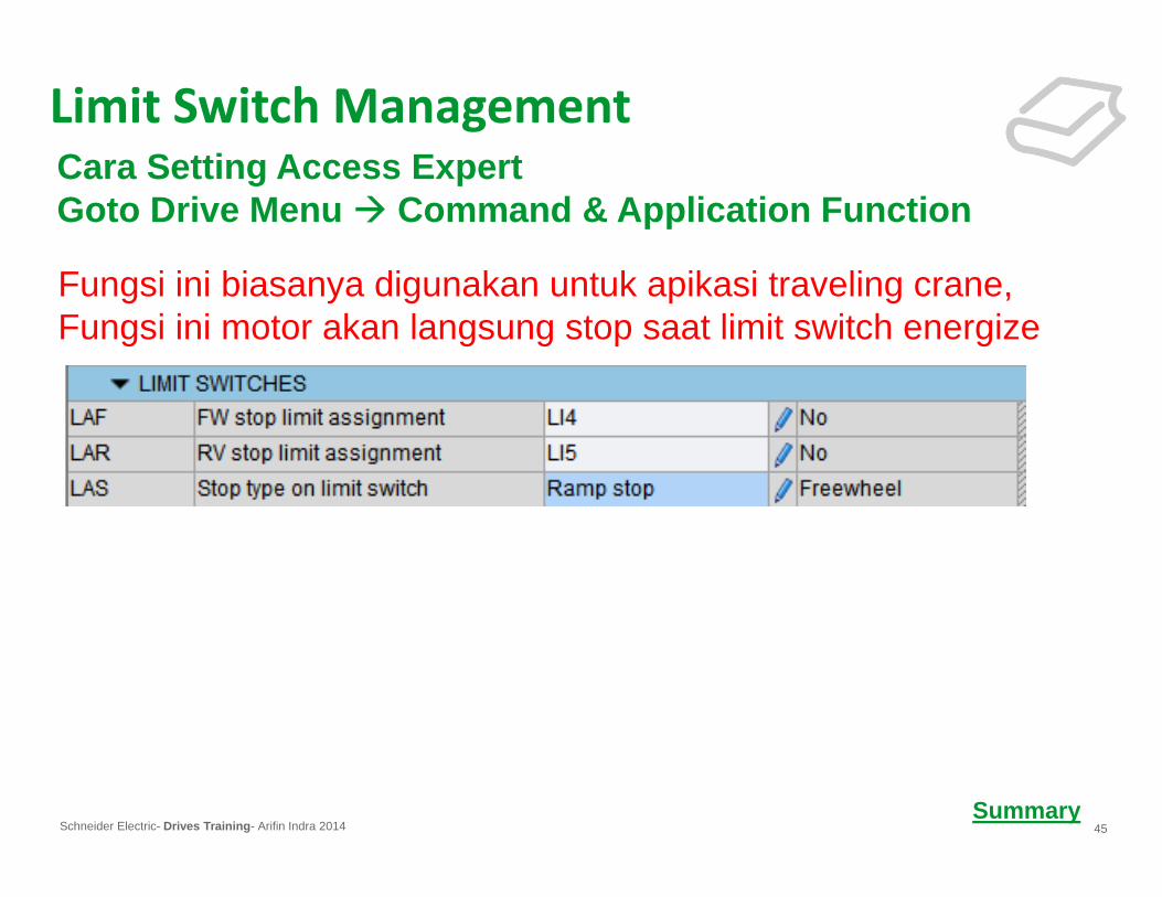
Speed feedback loop PI● Settings for a Low Inertia (x1 motor inertia)
Integral time constant SIT (SFC=65)
Pro
port
iona
l gai
n S
PG
Factory settings3x motor
inertia
Optimizedsettings
67Schneider Electric- Drives Training - Arifin Indra 2014Summary
67
Diagnostic
●Diagnostic● ATV71 has functions and menus facilitating the diagnostic of the product or on the
application.
They allow in particularly :
● Product and its options identification● Monitoring the logic I/O and communication words ● Displaying the last fault and Drive status at fault .● Test of the Drive (power and control).● Maintenance message displaying.● Temporal analysis parameters with the oscilloscope function.

68Schneider Electric- Drives Training - Arifin Indra 2014Summary
RUN Term + 50.00Hz 1250A LI1 ASSIGNMENT
FORWARDSWITCHING RAMP 2Delay time : 10 ms
<< >> Quick
Diagnostic● Menu 1 - Drive menu
1.2 - Monitoring ( SUP ) PENGECEKAN I/O dan AnalogI/O MAP : I/O Diagnostic
● This menu allows to display the image and configura tion of logic and analogic I/O so helps to diagnose a problem of wiring.
ENT ENT
LOGIC INPUTS :
LI 7 = 0
LI 8 = 1
OPERATING MODECONFIGURATION
RUN Term + 50.00Hz 1250A
LOGIC INPUTS IMAGEANALOGUE INPUTS IMAGELOGIC OUTPUTS IMAGEANALOGUE OUTPUTS IMAGEFREQ. SIGNALS IMAGECODE << >> Quick
I/O IMAGERUN Term + 50.00Hz 1250A
PR LI1 LI2 LI3 LI4 LI5 LI6
LI7 LI8 LI9 LI10 LI11 LI12 LI13 LI14
<< >> Quick
Logic Inputs MAP
1
0
1
0
STATE VISUALIZATION
USE ARROWS < < AND > > TO PASS FROM ONE LI to
ANOTHER

69Schneider Electric- Drives Training - Arifin Indra 2014Summary
● Menu 1 - Drive menu
1.2 - Monitoring ( SUP ) PENGECEKAN MODBUSIMAGE COM : CMD and REF WORD IMAGE
● This screen indicates the value of control word and reference speed, which transmit by all the channels other than the terminals and the graph ic keypad.
Diagnostic
RUN Term. +50.00Hz 1250A COM. IMAGE
COM. SCAN INCOM SCAN OUTCMD. WORD IMAGEREF. WORD IMAGEMODBUS NETWORK DIAGCODE << >> Quick
RUN Term. +50.00Hz 1250A CMD WORD IMAGE
Modbus Cmd : 000F HexCANopen Cmd : 000F HexNet Card Cmd : 000F HexProg. Card Cmd : 000F Hex
CODE << >> Quick
RUN Term. +50.00Hz 1250A REF WORD IMAGE
Modbus Ref : 0.0 HzCANopen Ref : 0.0 HzNet. Card Ref : 0.0 HzProg. Card Ref : 0.0 Hz
CODE << >> Quick

70Schneider Electric- Drives Training - Arifin Indra 2014Summary
● Menu 1 - Drive menu
1.2 - Monitoring (SUP)
IMAGE COM : MODBUS NETWOK DIAG
● This menu is dedicated to the diagnostic of communi cation network integrated into the Drive ( Modbus and CANopen ).
● It indicates if the network is operational, and dis play telegrams and errors counters
Diagnostic
RUN Term. +50.00Hz 1250A COM. IMAGE
CMD. WORD IMAGEREF. WORD IMAGEMODBUS NETWORK DIAGMODBUS CONSOLE DIAGCANopen NETWORK DIAGCODE << >> Quick
RUN Term + 50.00Hz 1250A MODBUS NETWORK DIAG
COM LED :Frame counter :Error counter :
CODE << >> Quick
RUN Term + 50.00Hz 1250A MODBUS CONSOLE DIAG
COM LED :Frame counter :Error counter :
CODE << >> Quick
RUN Term + 50.00Hz 1250A CANopen IMAGE
RUN LED :ERR LED :PDO 1 ImagePDO 2 imagePDO 3 ImageCODE << >> QuickFrame counter :Error counter :

71Schneider Electric- Drives Training - Arifin Indra 2014Summary
● Menu 1 - Drive menu1.10 – Diagnostic MELIHAT FAULT YANG TERJADI
This menu is available only with the keypad is used to :
● display the fault history and the present fault● test the drive internally ( power and control )● display the service message
Diagnostic
RUN Term. +50.00Hz 1250A 1.10- DIAGNOSTIC FAULT HISTORYPRESENT FAULT LISTADDITIONAL FAULT INFOTEST PROCEDURESERVICES MESSAGEHOME << >> Quick

72Schneider Electric- Drives Training - Arifin Indra 2014Summary
● Menu 1 - Drive menu1.10 - Diagnostic
Fault history
● Save the 8 last faults ● 12 parameters are memorised during the fault
● Drive status
● Status word
● Command word● Motor current
● Output frequency● Elapsed time
● DC bus voltage● ATV thermal state
● Command channel (terminal, modbus, …….)● Reference channel
● Year/month/day● Hour/minute
Diagnostic
with controller inside board
RUN Term. +50.00Hz 1250A FAULT HISTORY
SHORT CIRCUIT:40000 hOVERCURRENT : 3500 hEXTERNAL FLT : 3102 hOVERVOLTAGE : 1312 h
HELP << >> Quick
RUN Term. +50.00Hz 1250A SHORT CIRCUIT
FREQUENCY REF: 20.0HzCURRENT : 200.0 AMOTOR SPEED : 600 RPMOUTPUT FREQ : 600 RPMMACHINE SPEED: 1.2 msHELP << >> Quick

73Schneider Electric- Drives Training - Arifin Indra 2014Summary
● Menu 1 - Drive menu1.10 - Diagnostic
Test Procedure CEK THYRISTOR
To analyse a defective components in the drive with different tests like :
For customer :● Thyristor test (Only for ratings > 18,5KW)● Transistor test (with motor)
For maintenance =S= service :● LIC test (max current limit with motor)● Calibration of voltage (with multimeter)● Calibration of current (DC supply 8V 120A)● Braking transistor test (need to know the BR)
Diagnostic

74Schneider Electric- Drives Training - Arifin Indra 2014Summary
● ATV71 HC13N4
Maintenance

75Schneider Electric- Drives Training - Arifin Indra 2014Summary
● ATV71 HC13N4
Maintenance

76Schneider Electric- Drives Training - Arifin Indra 2014Summary
FAULT YANG SERING TERJADI
Maintenance