Asymptotic Solutions for Optical Properties of Large Particles with Strong Absorption
16
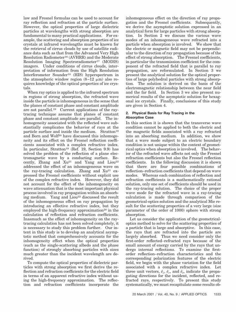
Asymptotic solutions for optical properties of large particles with strong absorption Ping Yang, Bo-Cai Gao, Bryan A. Baum, Yong X. Hu, Warren J. Wiscombe, Michael I. Mishchenko, Dave M. Winker, and Shaima L. Nasiri The transverse wave condition is not applicable to the refracted electromagnetic wave within the context of geometrical optics when absorption is involved. Either the TM or the TE wave condition can be assumed for the wave to locally satisfy the electromagnetic boundary condition in a ray-tracing calcu- lation. The assumed wave mode affects both the reflection and the refraction coefficients. As a result, nonunique solutions for these coefficients are inevitable. In this study the appropriate solutions for the Fresnel reflection–refraction coefficients are identified in light-scattering calculations based on the ray- tracing technique. In particular, a 3 3 2 refraction or transmission matrix is derived to account for the inhomogeneity of the refracted wave in an absorbing medium. An asymptotic solution that completely includes the effect of medium absorption on Fresnel coefficients is obtained for the scattering properties of a general polyhedral particle. Numerical results are presented for hexagonal plates and columns with both preferred and random orientations. © 2001 Optical Society of America OCIS codes: 010.1290, 010.1310, 010.3920, 290.5850, 290.1090, 280.1310. 1. Introduction The optical properties of dielectric particles such as aerosols and ice crystals in the atmosphere are fun- damental to a number of disciplines, including atmo- spheric radiation transfer and airborne or satelliteborne remote-sensing applications. In a re- cent book 1 Mishchenko et al. comprehensively re- viewed various methods that have been developed to solve the scattering and absorption properties of par- ticles for a variety of geometric morphologies and electromagnetic characteristics of the scatterers. Accurate numerical methods such as the discrete di- pole approximation method 2,3 and the finite- difference time-domain ~FDTD! technique 4,5 are applicable in practice only to size parameters smaller than 20 because the computational requirements in- crease quickly with size parameter. Although ana- lytical solutions are available for some particle shapes, such as spheres 6 and spheroids, 7,8 the corre- sponding numerical computations are usually quite challenging. For example, the computation of the optical properties of spheroids based on an analytical solution in terms of a series of special functions may not be stable when the size parameter is larger than approximately 30 – 40. It is worth noting that recent developments for the T-matrix method 9,10 permit ex- act solutions for the optical properties of spheroids and finite circular cylinders for size parameters up to 200. 11 There is no single method to solve for the optical properties of nonspherical particles across the entire size parameter spectrum. It is common to use the ray-tracing technique 12–15 for nonspherical particles that have sizes much larger than the incident wavelength. Previous applica- tions of the ray-tracing technique were focused pri- marily on scattering computations for the visible and near-infrared wavelengths, for which the imaginary part of the refractive index is small. For these weakly absorptive spectra, the conventional Snell P. Yang ~[email protected]! and W. J. Wiscombe are with the NASA Goddard Space Flight Center, Code 913, Greenbelt, Maryland 20771. P. Yang is also with Science Systems and Ap- plications, Inc., Suite 300, 5900 Princess Garden Parkway, Lan- ham, Maryland 20706. B.-C. Gao is with the Remote Sensing Division, Code 7212, U.S. Naval Research Laboratory, Washing- ton, D.C. 20375. B. A. Baum, Y. X. Hu, and D. M. Winker are with the Atmospheric Sciences Division, MS 420, NASA Langley Re- search Center, Hampton, Virginia 23681. M. I. Mishchenko is with the NASA Goddard Institute for Space Studies, 2880 Broad- way, New York, New York 10025. S. L. Nasiri is with the Coop- erative Institute for Meteorological Satellite Studies, University of Wisconsin–Madison, 1225 West Dayton Street, Madison, Wiscon- sin 53706. Received 11 July 2000; revised manuscript received 29 Novem- ber 2000. 0003-6935y01y091532-16$15.00y0 © 2001 Optical Society of America 1532 APPLIED OPTICS y Vol. 40, No. 9 y 20 March 2001
Transcript of Asymptotic Solutions for Optical Properties of Large Particles with Strong Absorption

wMphDttswweWs
b
Asymptotic solutions for optical properties oflarge particles with strong absorption
Ping Yang, Bo-Cai Gao, Bryan A. Baum, Yong X. Hu, Warren J. Wiscombe, Michael I. Mishchenko,Dave M. Winker, and Shaima L. Nasiri
The transverse wave condition is not applicable to the refracted electromagnetic wave within the contextof geometrical optics when absorption is involved. Either the TM or the TE wave condition can beassumed for the wave to locally satisfy the electromagnetic boundary condition in a ray-tracing calcu-lation. The assumed wave mode affects both the reflection and the refraction coefficients. As a result,nonunique solutions for these coefficients are inevitable. In this study the appropriate solutions for theFresnel reflection–refraction coefficients are identified in light-scattering calculations based on the ray-tracing technique. In particular, a 3 3 2 refraction or transmission matrix is derived to account for theinhomogeneity of the refracted wave in an absorbing medium. An asymptotic solution that completelyincludes the effect of medium absorption on Fresnel coefficients is obtained for the scattering propertiesof a general polyhedral particle. Numerical results are presented for hexagonal plates and columns withboth preferred and random orientations. © 2001 Optical Society of America
OCIS codes: 010.1290, 010.1310, 010.3920, 290.5850, 290.1090, 280.1310.
1. Introduction
The optical properties of dielectric particles such asaerosols and ice crystals in the atmosphere are fun-damental to a number of disciplines, including atmo-spheric radiation transfer and airborne orsatelliteborne remote-sensing applications. In a re-cent book1 Mishchenko et al. comprehensively re-viewed various methods that have been developed tosolve the scattering and absorption properties of par-ticles for a variety of geometric morphologies and
P. Yang [email protected]! and W. J. Wiscombe areith the NASA Goddard Space Flight Center, Code 913, Greenbelt,aryland 20771. P. Yang is also with Science Systems and Ap-
lications, Inc., Suite 300, 5900 Princess Garden Parkway, Lan-am, Maryland 20706. B.-C. Gao is with the Remote Sensingivision, Code 7212, U.S. Naval Research Laboratory, Washing-
on, D.C. 20375. B. A. Baum, Y. X. Hu, and D. M. Winker are withhe Atmospheric Sciences Division, MS 420, NASA Langley Re-earch Center, Hampton, Virginia 23681. M. I. Mishchenko isith the NASA Goddard Institute for Space Studies, 2880 Broad-ay, New York, New York 10025. S. L. Nasiri is with the Coop-rative Institute for Meteorological Satellite Studies, University ofisconsin–Madison, 1225 West Dayton Street, Madison, Wiscon-
in 53706.Received 11 July 2000; revised manuscript received 29 Novem-
er 2000.0003-6935y01y091532-16$15.00y0© 2001 Optical Society of America
1532 APPLIED OPTICS y Vol. 40, No. 9 y 20 March 2001
electromagnetic characteristics of the scatterers.Accurate numerical methods such as the discrete di-pole approximation method2,3 and the finite-difference time-domain ~FDTD! technique4,5 areapplicable in practice only to size parameters smallerthan 20 because the computational requirements in-crease quickly with size parameter. Although ana-lytical solutions are available for some particleshapes, such as spheres6 and spheroids,7,8 the corre-sponding numerical computations are usually quitechallenging. For example, the computation of theoptical properties of spheroids based on an analyticalsolution in terms of a series of special functions maynot be stable when the size parameter is larger thanapproximately 30–40. It is worth noting that recentdevelopments for the T-matrix method9,10 permit ex-act solutions for the optical properties of spheroidsand finite circular cylinders for size parameters up to200.11 There is no single method to solve for theoptical properties of nonspherical particles across theentire size parameter spectrum.
It is common to use the ray-tracing technique12–15
for nonspherical particles that have sizes much largerthan the incident wavelength. Previous applica-tions of the ray-tracing technique were focused pri-marily on scattering computations for the visible andnear-infrared wavelengths, for which the imaginarypart of the refractive index is small. For theseweakly absorptive spectra, the conventional Snell
tphsp
ponwpi
a
oatlfisdocfiat
law and Fresnel formulas can be used to account forray reflection and refraction at the particle surface.However, the optical properties of large dielectricparticles at wavelengths with strong absorption arefundamental to many practical applications. For ex-ample, the scattering and absorption properties of icecrystals at infrared wavelengths must be known forthe retrieval of cirrus clouds by use of satellite radi-ance data such as that from the Advanced Very HighResolution Radiometer16 ~AVHRR! and the ModerateResolution Imaging Spectroradiometer17 ~MODIS!imagers. Under conditions of cirrus clouds, inter-pretation of information from the High ResolutionInterferometer Sounder18 ~HIS! hyperspectrum inthe atmospheric window region ~8–12 mm! also re-quires knowledge of the optical properties of ice crys-tals.
When ray optics is applied to the infrared spectrumin regions of strong absorption, the refracted waveinside the particle is inhomogeneous in the sense thatthe planes of constant phase and constant amplitudeare not parallel.19 Current applications of the ray-racing technique assume that planes of constanthase and constant amplitude are parallel. The in-omogeneity associated with the reflected wave sub-tantially complicates the behavior of rays at thearticle surface and inside the medium. Stratton19
and Born and Wolf20 have discussed this inhomoge-neity and its effect on the Fresnel reflection coeffi-cients associated with a complex refractive index.In particular, Stratton19 ~Ref. 19, Section 9.9! hassolved the problem of the reflection of a plane elec-tromagnetic wave by a conducting surface. Re-cently, Zhang and Xu21 and Yang and Liou22
addressed the effect of an inhomogeneous wave onthe ray-tracing calculation. Zhang and Xu21 ex-
ressed the Fresnel coefficients without explicit usef the complex refractive index. However, they didot account for the effect of the inhomogeneity onave attenuation that is the most important physicalrocess involved in ray propagation within an absorb-ng medium. Yang and Liou22 discussed the result
of the inhomogeneous effect on ray propagation byintroducing an effective refractive index, but theyemployed the high-frequency approximation20 in thecalculation of reflection and refraction coefficients.Inasmuch as the effect of inhomogeneity on the ray-tracing calculation has not been solved completely, itis necessary to study this problem further. Our in-tent in this study is to develop an analytical asymp-totic method that comprehensively accounts for theinhomogeneity effect when the optical properties~such as the single-scattering albedo and the phasefunction! of strongly absorbing particles with sizesmuch greater than the incident wavelength are de-rived.
To compute the optical properties of dielectric par-ticles with strong absorption we first derive the re-flection and refraction coefficients for the electric fieldin terms of an apparent refractive index without us-ing the high-frequency approximation. The reflec-tion and refraction coefficients incorporate the
inhomogeneous effect on the direction of ray propa-gation and the Fresnel coefficients. Subsequently,we derive the asymptotic solution expressed in ananalytical form for large particles with strong absorp-tion. In Section 2 we discuss the various wavemodes of an inhomogeneous wave refracted into aparticle when absorption is involved. We show thatthe electric or magnetic field may not be perpendic-ular to the direction of ray propagation because of theeffect of strong absorption. The Fresnel coefficients,in particular the transmission coefficient for the com-ponent of the refracted field that is parallel to raypropagation, are reformulated. In Section 3 wepresent the analytical solution for the optical proper-ties of large polyhedral particles with strong absorp-tion. The solution is derived on the basis of theelectromagnetic relationship between the near fieldand the far field. In Section 3 we also present nu-merical results of the asymptotic solution for hexag-onal ice crystals. Finally, conclusions of this studyare given in Section 4.
2. Physical Basis for Ray Tracing in theAbsorptive Case
In this section it is shown that the transverse wavecondition cannot be applied to both the electric andthe magnetic fields associated with a ray refractedinto an absorbing medium. In addition, we showthat a wave mode subject to an electric boundarycondition is not unique within the context of geomet-rical optics when absorption is involved. The behav-ior of the refracted wave affects not only the Fresnelrefraction coefficients but also the Fresnel reflectioncoefficients. In the following discussion it is shownthat there are four possible combinations ofreflection–refraction coefficients that depend on wavemodes. Whereas each combination of reflection andrefraction coefficients is a mathematically rationalsolution, only one set of coefficients should be used inthe ray-tracing solution. The choice of the properwave mode for the refracted wave in a ray-tracingcalculation is made through comparison of thegeometrical-optics solution and the analytical Mie re-sult for the scattering properties of a very large ~sizeparameter of the order of 1000! sphere with strongbsorption.Let us consider the application of the geometrical-
ptics method to solve for the scattering properties ofparticle that is large and absorptive. In this case,
he rays that are refracted into the particle areargely absorbed. Thus we need consider only therst-order reflected–refracted rays because of themall amount of energy carried by the rays that un-ergo internal reflections. To examine the first-rder reflection–refraction characteristics and theorresponding polarization features of the electriceld, we begin with the phase variation for the fieldssociated with a complex refractive index. Lethree unit vectors, ei, er, and et, indicate the propa-
gating directions for the incident, reflected, and re-fracted rays, respectively. To present this studysystematically, we must recapitulate some results ob-
20 March 2001 y Vol. 40, No. 9 y APPLIED OPTICS 1533
22
t
iN
fi
ifsia
1
tained by Yang and Liou. Following those au-thors, the fields associated with these rays can bewritten as follows:
Ei~r! 5 Eio exp~ikei z r!, (1a)
Er~r! 5 Ero exp~iker z r!, (1b)
Et~r! 5 Eto exp@ik~Nret 1 iNnn! z r#, (1c)
where Eio, Ero, and Eto are the amplitude vectors forhe fields; k 5 2pyl, in which l is the wavelength in
vacuum; and n is a unit vector that is normal to theparticle surface and to points into the particle. Theparameters Nr and Nn in Eq. ~1c! are given by
Nr 5 221y2$mr2 2 mi
2 1 sin2 zi
1 @~mr2 2 mi
2 2 sin2 zi!2 1 4mr
2mi2#1y2%1y2, (1d)
Nn 5 221y2$2~mr2 2 mi
2 2 sin2 zi!
1 @~mr2 2 mi
2 2 sin2 zi!2 1 4mr
2mi2#1y2%1y2, (1e)
in which mr and mi are the real and the imaginaryparts, respectively, of the refractive index and zi is thencident angle, given by zi 5 sin21@1 2 ~ei z n!2#1y2.ote that Nn ~denoted Ni* in Ref. 22! was not pre-
sented in the previous study. Physically, Nr is theparameter that determines the phase and Nn is theparameter that determines the absorption, as we il-lustrate in the following discussion.
From Eqs. ~1a!–~1c! and the continuity of the wavephase at the medium interface, it follows that Snell’slaw for an absorbing medium can be mathematicallyexpressed in the form
er 5 ei 1 2~ei z n!n, (2a)
et 5 eiyNr 1 ~cos zt 2 cos ziyNr!n, (2b)
where the refractive angle is given by zt 5sin21@sin~zi!yNr#. Equation ~2a! means that the in-cident and reflected rays are spatially symmetricabout the direction normal to the particle surface atthe incident point, which is the standard Snell law forthe reflection direction. However, Eq. ~2b! indicatesthat the refracted direction is determined not by mrbut by Nr. For this reason, Nr is referred to as thereal part of the apparent refractive index, which de-pends on the incident configuration and the dielectricconstant of the medium for determining the directionand the phase of a refracted wave. The attenuationof a refracted field as a result of absorption dependson the direction of observation. If the direction isalong n, the attenuation is determined by Nn, as isevident from Eq. ~1c!. However, if we trace the re-racted wave along the direction of the refracted ray,.e., along position vector r 5 let, in which l is the
penetration depth of the ray, the electric field is givenby
Et~let! 5 Eto exp@2kNn~n z et!l#exp~ikNr l !. (3)
Obviously, the factor Nn~n z et! is the imaginary partof the apparent refractive index that governs the at-
534 APPLIED OPTICS y Vol. 40, No. 9 y 20 March 2001
tenuation of the electric field associated with therays. We denote this factor Ni. Thus, for a ray thatimpinges upon an absorbing medium, the apparentrefractive index in the complex format is ~Nr 1 iNi!.It can be proved that
Ni 5 Nn~n z et! 5 Nn cos zt 5 mr miyNr. (4)
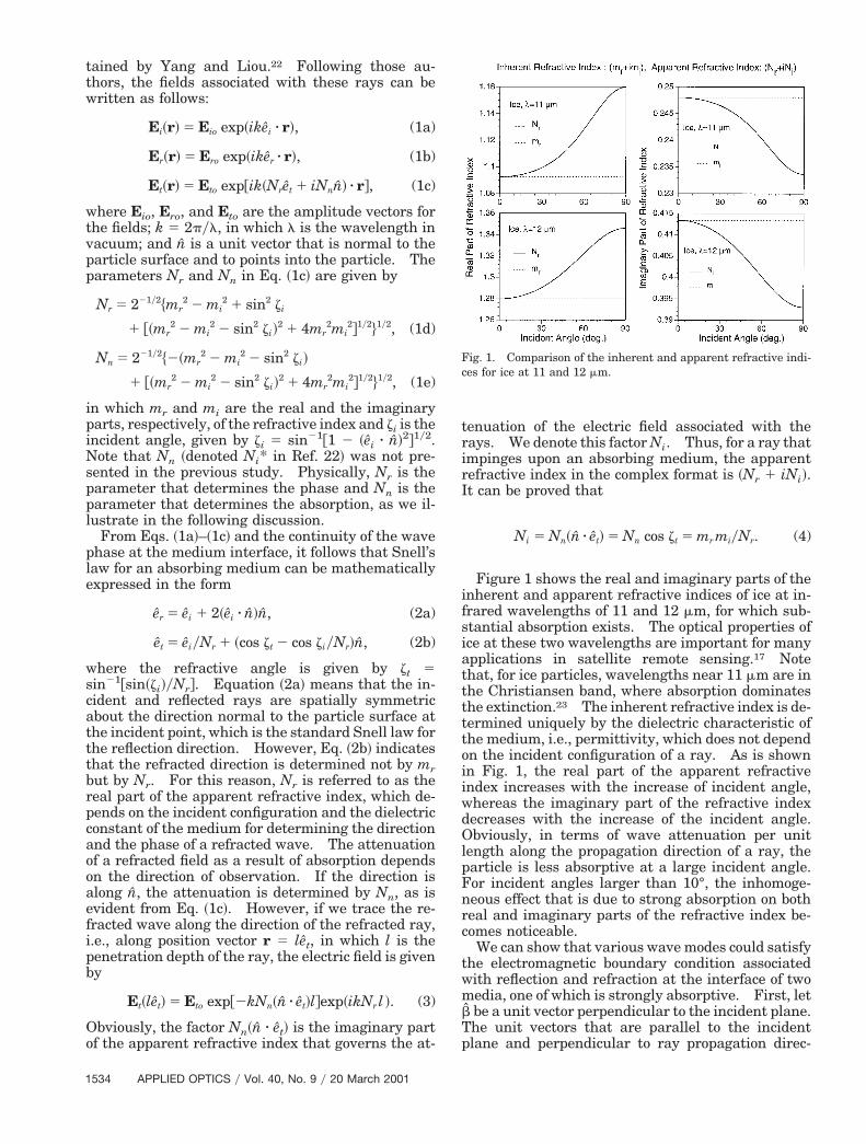
Figure 1 shows the real and imaginary parts of thenherent and apparent refractive indices of ice at in-rared wavelengths of 11 and 12 mm, for which sub-tantial absorption exists. The optical properties ofce at these two wavelengths are important for manypplications in satellite remote sensing.17 Note
that, for ice particles, wavelengths near 11 mm are inthe Christiansen band, where absorption dominatesthe extinction.23 The inherent refractive index is de-termined uniquely by the dielectric characteristic ofthe medium, i.e., permittivity, which does not dependon the incident configuration of a ray. As is shownin Fig. 1, the real part of the apparent refractiveindex increases with the increase of incident angle,whereas the imaginary part of the refractive indexdecreases with the increase of the incident angle.Obviously, in terms of wave attenuation per unitlength along the propagation direction of a ray, theparticle is less absorptive at a large incident angle.For incident angles larger than 10°, the inhomoge-neous effect that is due to strong absorption on bothreal and imaginary parts of the refractive index be-comes noticeable.
We can show that various wave modes could satisfythe electromagnetic boundary condition associatedwith reflection and refraction at the interface of twomedia, one of which is strongly absorptive. First, letb be a unit vector perpendicular to the incident plane.The unit vectors that are parallel to the incidentplane and perpendicular to ray propagation direc-
Fig. 1. Comparison of the inherent and apparent refractive indi-ces for ice at 11 and 12 mm.

I
Fttcw
rvcvrmi
o
n
e
Tta
tions for the incident, reflected, and refracted wavesare given by
ai 5 ei 3 b, ar 5 er 3 b, at 5 et 3 b. (5)
t should be pointed out that bai,r,tei,r,t constitute right-handed coordinate systems. The incident and re-flected waves are within the nonabsorbing medium.As a result of the homogeneous wave properties of theincident and reflected rays, the condition of a trans-verse wave ~hereafter referred to as the TEM mode!can be imposed on both electric and magnetic fields forthese rays. Thus the corresponding amplitude vec-tors of the electric fields can be decomposed in the form
Eio 5 Eio,aai 1 Eio,bb, (6a)
Ero 5 Ero,aar 1 Ero,bb. (6b)
The Maxwell equations in time-independent form aregiven by
E~r! 5 ¹ 3 H~r!y~2ikε!, (7a)
H~r! 5 ¹ 3 E~r!yik, (7b)
where ε is permittivity, given by ε 5 ~mr 1 imi!2.
We have chosen the time-harmonic factor asexp~ikct!, in which c is the speed of light in vacuum.If this factor is selected as exp~2ikct!, the sign of theimaginary part of the refractive index is negative.1,24
Using Eq. ~7b!, we can obtain the amplitude vectors ofmagnetic fields associated with the incident and re-flected rays as follows:
Hio 5 ei 3 ~Eio,aai 1 Eio,bb! 5 Eio,bai 2 Eio,ab, (8a)
Hro 5 er 3 ~Ero,aar 1 Ero,bb! 5 Ero,bar 2 Ero,ab. (8b)
or the refractive wave in an absorbing medium, aransverse-wave condition cannot be imposed simul-aneously on the electric and the magnetic fields be-ause of the inhomogeneity effect; that is, the TEMave mode is not valid in this case.In the following discussion, first we examine the
eflecting characteristics of an absorbing medium forarious wave modes. To derive the reflection coeffi-ient, we can assume that the electric field is trans-erse with respect to the propagation direction of theay ~hereafter this mode is referred to as the TEode!, so the refracted electric field can be expressed
n the form
Eto 5 Eto,aat 1 Eto,bb. (9)
From Eqs. ~1c!, ~4!, ~7b!, and ~9! and the relationshipf n 5 cos ztet 2 sin ztat, the refracted magnetic field
in the TE mode can be obtained as follows:
Hto~r! 5 ~Nret 1 iNnn! 3 ~Eto,aat 1 Eto,bb!
5 ~Nr 1 iNi!Eto,bat 2 ~Nr 1 iNi!Eto,ab
1 iNn sin zt Eto,bet. (10)
From Eq. ~10! it is evident that the refracted mag-etic field has a nonzero component along unit vector
ˆt ~ray direction! when Nn is not zero, i.e., when ab-sorption is involved. At the interface of two media,the electromagnetic boundary condition requires thatthe tangential components of electric and magneticfields be continuous. Thus we have the followingrelationships:
Eio,b 1 Ero,b 5 Eto,b, (11a)
Eio,b cos zi 2 Ero,b cos zi 5 @~Nr 1 iNi!cos zt
1 iNn sin2 zt#Eto,b, (11b)
Eio,a 1 Ero,a 5 ~Nr 1 iNi!Eto,a, (11c)
Eio,a cos zi 2 Ero,a cos zi 5 cos zt Eto,a. (11d)
The preceding equations can be solved to yield thereflection coefficients for the two polarization config-urations:
RTE,' 5 Ero,byEio,b
5cos zi 2 @~Nr 1 iNi!cos zt 1 iNn sin2 zt#
cos zi 1 @~Nr 1 iNi!cos zt 1 iNn sin2 zt#
5cos zi 2 ~Nr cos zt 1 iNn!
cos zi 1 ~Nr cos zt 1 iNn!, (12a)
RTE,\ 5 Ero,ayEio,a 5~Nr 1 iNi!cos zi 2 cos zt
~Nr 1 iNi!cos zi 1 cos zt.
(12b)
Similarly, if we assume that the magnetic field of therefracted wave is transverse with respect to the raydirection ~hereafter, this mode is referred to as the TMmode!, the reflection coefficients are then given by
RTM,' 5~Nr 1 iNi!cos zi 2 ε cos zt
~Nr 1 iNi!cos zi 1 ε cos zt, (13a)
RTM,\ 5ε cos zi 2 ~Nr cos zt 1 iNn!
ε cos zi 1 ~Nr cos zt 1 iNn!. (13b)
herefore, considering the two wave modes andwo polarization configurations, four combinationsre possible for the reflection coefficients: ~RTM,\,
RTM,'!, ~RTE,\, RTE,'!, ~RTE,\, RTM,'!, and ~RTM,\,RTE,'!. Each of these four combinations is a math-ematically rational solution derived from the electro-magnetic boundary condition when an absorptivemedium is involved. However, only one of the foursolutions should be computationally correct in theray-tracing calculation relative to the process of scat-tering an electromagnetic wave by a dielectric parti-cle with absorption. It should be pointed out thatthe Maxwell equations, subject to the appropriateboundary conditions, always have a unique solution,as in the case of Mie theory. The explanation for themultiple solutions for the reflection coefficients isthat the electromagnetic boundary condition is lo-cally imposed within the context of geometrical op-tics, which permits treatment of the inhomogeneousrefracted wave as a refracted ray, thereby providing
20 March 2001 y Vol. 40, No. 9 y APPLIED OPTICS 1535

ossp
d
t
r
1
the basis for a ray-tracing procedure. Accordingly,we are looking for the pair of reflection coefficientsthat provide the best numerical agreement with theexact solution in scattering computation.
To identify the computationally correct pair of re-flection coefficients from among the preceding fourcombinations, we consider the scattering geometry inFig. 2 for a strongly absorptive sphere with a sizemuch larger than incident wavelength. In this casethe scattered field is composed primarily of the con-tributions from diffraction and external reflection.The incident energy associated with area element dsn the projected area is scattered in angular elementin ududw in which u is the scattering angle. Thecattered intensity at a distance r that is far from thearticle is given by
Is 5 I0
uRu2
r2 U dssin ududw
U 5 I0
uRu2a2
4r2 , (14)
where a is the radius of the sphere; I0 and Is areincident and scattered intensities, respectively; R is areflection coefficient without specification of a wavemode and polarization configuration. To derive Eq.~14! we used two relationships, ds 5 a2 cos zi sinzidzidw and u 5 p 2 2zi. However, according to the
efinition of the scattering phase function denoted P,one can define the following relationship:
Is 5ss
4pr2 PI0, (15)
Fig. 2. Scattering geometry for a large sphere with strong ab-sorption.
DLP~u! 5I'
d~u! 2 I\d~u! 1 I'
r~u! 2 I\r~u!
I'd~u! 1 I\
d~u! 1 I'r~u! 1 I\
r~u!5
~ka!2@2J1~ka~ka!2@2J1~ka
536 APPLIED OPTICS y Vol. 40, No. 9 y 20 March 2001
where ss is the scattering cross section. Therefore,after the two polarization configurations are ac-counted for, the contribution of the external reflectionto the phase function can be obtained by a comparisonof Eqs. ~14! and ~15!:
Pr~u! 512
~uR\u2 1 uR'u2!pa2
ss
512
~uR\u2 1 uR'u2!Qe 2 Qa
, (16)
where Qe and Qa are the extinction efficiency and theabsorption efficiency, respectively. The value of Qeis 2 because the particle is very large, whereas Qa isdetermined by the ratio of refracted energy to theincident energy associated with the projected area.Note that the divergence factor introduced by van deHulst25 is absent in Eq. ~16! because the rays that areransmitted through the sphere are ignored here.
An improved diffraction formulation has been de-ived by Yang and Liou26 that, unlike the conven-
tional method that is limited to scattering anglessmaller than 90°, can be applied to the entire scat-tering angular region. When the improved methodis applied to the diffraction by a sphere, the scatter-ing amplitude matrix25 is given by
FS2 S3
S4 S1G 5
~ka!2
42J1~ka sin u!
ka sin u
3 Fcos u~1 1 cos u! 00 1 1 cos uG , (17)
where J1 is the Bessel function of the first kind. Thephase function that includes the contribution fromdiffraction and external reflection can be obtainedfrom Eqs. ~16! and ~17! as follows:
P~u! 5~ka!2
8~Qe 2 Qa!F2J1~ka sin u!
ka sin u G2
3 ~1 1 cos2 u!~1 1 cos u!2 112
~uR\u2 1 uR'u2!Qe 2 Qa
.
(18)
In addition to the phase function, one should use thepolarization configuration to identify the correct com-bination of reflection coefficients. When the inci-dent radiation is unpolarized, the polarizationfeature of scattered radiation can be specified by thedegree of linear polarization ~DLP!. When scatteredradiation is composed of diffraction and external re-flection, the DLP associated with the phase functionin Eq. ~18! can be given as follows:
u!yka sin u#2~1 1 cos u!2~1 2 cos2 u! 1 4~uR'u2 2 uR\u2!u!yka sin u#2~1 1 cos u!2~1 1 cos2 u! 1 4~uR'u2 1 uR\u2!
,
(19)
sinsin

d r d r
tflpa
cmt
cTtrctldituptc
tarflHcptcttFrigra
th
b
where I' and I' ~I\ and I\ ! are the scattered in-ensity associated with diffraction and external re-ection, respectively, when the electric field isolarized along a direction that is perpendicular ~par-llel! to the scattering plane.Figure 3 shows the phase function and the DLP
omputed from Mie theory and the geometrical-opticsethod at a wavelength of 12 mm. The Mie compu-
ational code developed by Wiscombe27 is used in thisstudy. Because the size parameter is extremelylarge ~x 5 1047.2!, the scattered energy at a largescattering angle ~approximately 20° in this case!omes primarily from the reflection of incident rays.hrough comparison of the geometrical-optics solu-
ion and the Mie results, we can identify the correcteflection coefficient pair. Evidently, the reflectionoefficient pair ~RTM,\, RTE,'! produces a phase func-ion and a DLP consistent with the Mie solution atarge scattering angles, where the external reflectionominates. As the Mie solution for the DLP is pos-tive for the entire scattering domain, the reflection ofhe incident wave with a vertical polarization config-ration is much larger than the reflection when theolarization is parallel to the scattering plane. Forhis reason, if we incorrectly apply reflection coeffi-ient RTM,' for the incident wave polarized perpen-
dicularly with respect to scattering plane, substantialerrors can result for both phase function and DLP, asis evident from Fig. 3.
Figure 4 is similar to Fig. 3, except that the wave-length is 11 mm and the real part of the refractiveindex is close to unity ~see Fig. 1!. It can be seenhat the phase function values at large scatteringngles at 11 mm are much smaller than the cor-esponding results at 12 mm because external re-ection is weaker for the former wavelength.owever, the correctness of the reflection coeffi-
ients used in the computation is also critical to thehase function and the DLP, even in the opticallyenuous case. As a matter of fact, the errors asso-iated when the wrong wave mode is assumed forhe refracted wave are even more pronounced forhe results shown in Fig. 4 than for those shown inig. 3. From these results it is clear that the cor-ect wave mode must be used for the refracted waven the derivation of the reflection coefficients, re-ardless of the magnitude of the real part of theefractive index whenever the particle is stronglybsorptive.A comparison of the ray-tracing method and Mie
heory for obtaining the phase function of spheresas been presented by Liou and Hansen28 for a
polydispersive case that has an assumed particlesize distribution. For the monodispersive case ~asystem composed of particles that have a single sizeand shape!, a comparison study has been presented
y Macke et al.29 for spheroids and finite circularcylinders at a near-infrared wavelength, which
Fig. 3. Phase function and the degree of linear polarization com-puted from geometrical optics compared with the Mie solution atl 5 12 mm.
Fig. 4. The same as Fig. 3, except that here the wavelength is11 mm.
20 March 2001 y Vol. 40, No. 9 y APPLIED OPTICS 1537

1
shows that the applicable size parameter for thegeometrical-optics method is approximately 60. Inaddition, these authors29 pointed out that thesize parameter required for a convergence ofthe exact solution and the geometrical-optics solu-tion is larger for spheres than for nonspherical par-ticles.
The results of this study suggest that thegeometrical-optics method can be applied to muchsmaller size parameters when strong absorption isinvolved. Figure 5 shows the phase function com-puted from Eq. ~18! in comparison with the Mie so-lutions. Evidently, when the size parameter islarger than approximately 30, one can use thegeometrical-optics solution to approximate the exactsolution. For size parameters larger than 50, thegeometrical-optics solution essentially converges tothe exact solution in the side and backscattering di-rections.
From the preceding discussions associated withFigs. 3–5, it is clear that TM and TE modes shouldbe applied to the components of electric fieldsthat are parallel and perpendicular, respectively,to the incident plane. By using this combinationof wave modes, one can straightforwardly derivethe refracted wave on the basis of electromag-netic boundary conditions. Through applicationof the ~TM\, TE'! wave mode to the refracted
Fig. 5. Comparison of the phase functions computed from Mie that wavelengths of 11 and 12 mm.
538 APPLIED OPTICS y Vol. 40, No. 9 y 20 March 2001
wave, we can obtain the refracted electric field asfollows:
Et,o 5 Et,o,aat 1 Et,o,bb 1 Et,o,get, (20a)
SEto,a
Eto,b
Eto,g
D 5 FTa 00 Tb
Tg 0GSEio,a
Eio,bD , (20b)
where
Ta 52~Nr 1 iNi!cos zi
ε cos zi 1 ~Nr cos zt 1 iNn!, (20c)
Tb 52 cos zi
cos zi 1 ~Nr cos zt 1 iNn!, (20d)
Tg 5i2Nn sin zt cos zi
ε cos zi 1 ~Nr cos zt 1 iNn!. (20e)
Note that in Eqs. ~20! the dependence of theseparameters on the wave mode is not specified explic-itly. It should be pointed out that the transmissionmatrix in the conventional ray-tracing scheme is a2 3 2 matrix. When absorption is involved, thetransmission matrix becomes a 3 3 2 matrix. Whenabsorption of the medium is absent, Tg is reduced tozero because Nn is zero and Eqs. ~20! are reduced to
and from the geometrical-optics method for three moderate sizes
eory
r
pfitfid
the conventional Fresnel refraction coefficients.
3. Asymptotic Solution for Scattering and AbsorptionProperties of Large Polyhedral Particles with StrongAbsorption
A. Physical Basis for the Asymptotic Solution
In Section 2 it was shown that the conventionalgeometrical-optics approach in terms of the superpositionof diffraction and external reflection can well approxi-mate the Mie solution for the spherical-particle casewhen the size parameter is large and the particle is ab-sorptive. Because the variation in the surface normaldirection is continuous for a sphere, a continuous distri-bution of the externally reflected energy is obtained.However, this is not true if the particle geometry is apolyhedron such as a hexagonal plate or column, which isthe basic geometric structure of ice crystals in cirrusclouds. In the numerical solution, there is a physicallyincorrect discontinuous distribution of scattered energyfor any specific orientation of the particle.
For example, consider the scattering of radiationby a hexagonal ice column when the incident radia-tion is perpendicular to the c axis of the particle andparallel to a line that connects two symmetric apexesof particle cross section. If the rays refracted intothe particle are ignored because of absorption, thephase function can be written as follows:
where L and a are the length and the semiwidth,espectively, of the hexagonal columns and d~x! is the
Dirac delta function. To avoid any possible confu-sion, in Eqs. ~21! we use us to indicate the scatteringangle and ws for the azimuthal angle of the scatteringplane. Here the plane of ws 5 0° is the plane thatcontains the incident direction and the c axis of the
article. On the right-hand side of Eq. ~21a!, therst term represents the contribution from diffrac-ion and the second term represents the contributionrom external reflection. Obviously, the second terms nonzero at only two angles, as is expressed by theelta functions. This singularity is inherent in the
conventional geometrical-optics method. The deltareflection involved in Eqs. ~21! originates from thesame physical mechanism of the forward delta trans-mission that has been well explained by Takano andLiou12 and Mishchenko and Macke.30 It should bepointed out that the singularity in Eq. ~21b! could beovercome numerically in the ray-tracing calculation ifthe particles were randomly oriented in space. Theaverage intensity is given by the scattered energydivided by the corresponding solid angle elements.The discontinuity could be avoided, given proper res-olution for the solid angle elements with sufficientorientations of the particles, i.e., with sufficientlyrandom orientation.
To circumvent this particular disadvantage of theconventional method for a specific orientation, weapply the geometrical-optics method to solve for theinternal field inside the particle, following Yang andLiou.31 The scattered far-field, extinction, and ab-sorption cross sections are given by
Es~r! 5k2 exp~ikr!
4pr~ε 2 1! ***
n
$E~r*! 2 r@r z E~r*!#%
3 exp~2ikr z r!d3r9, (22a)
sext 5 Im3 kuEiu
~ε 2 1!***n
E~r*!Ei~r*!4d3r9, (22b)
sabs 5k
uEiu2εi ***
n
E~r*! z Ei~r*!d3r9, (22c)
respectively. The integrals involved in Eqs. ~22! can becalculated by use of the ray-by-ray integration algo-rithm.31 From the ray-by-ray integration calculationand Eqs. ~22!, the amplitude scattering matrix and theextinction and absorption cross sections are given by
P~us, ws! 53k2 La8pss
Hsin@~kLy2!sin us cos ws#
~kLy2!sin us cos ws
sin@~Î3 kay2!sin us sin ws#
~Î3 kay2!sin us sin wsJ2
3 ~1 1 cos2 us!~1 1 cos us!2
1Î3 paL
ss@d~ws 2 py2! 1 d~ws 1 py2!#d~us 2 2py3!#~uRTM,\,zi5py6u2 1 uRTE,',zi5py6u2!, (21a)
ss 5 Î3aL~2 2 uRTM,\,zi5py6u2 2 uRTE,',zi5py6u2!, (21b)
FS2~es! S3~es!S4~es! S1~es!
G 5k2~ε 2 1!
4p **surface
cos zi
Nr 1 iNi 2 es z etFas z at as z b as z es
bs z at bs z b bs z esGFTa 0
0 Tb
Tg 0G Fai z a0 ai z bs
b z a0 b z bsG
3 exp@2ik~ei 2 es! z r*#$1 2 exp@2kNil~r*!#exp@ik~Nr 2 es z et!l~r*!#%d2r9, (23a)
20 March 2001 y Vol. 40, No. 9 y APPLIED OPTICS 1539
t
0r~t
rbpd
w
1
sext 52p
k2 Re@S1~ei! 1 S2~ei!#, (23b)
sabs 512 **
particle surface
cos ztNr~uTau2 1 uTbu2 1 uTgu2!
3 $1 2 exp@22kNil~r9!#%d2r9, (23c)
where bs is a unit vector perpendicular to the scat-ering plane, es is along the scattering direction, as 5
es 3 bs, ao 5 ei 3 bs, and l~r9! is the ray penetrationdepth with the incident point at r9. The other vari-ables involved were defined above. If the absorbingparticle is large, it is expected that exp@2kNil~r9!#3. In this case, analytical expressions can be de-ived for the integrations involved in Eqs. ~23a! and23c! if the surface of the particle is locally flat, as inhe case of polyhedral geometry.
For a given flat face of the particle surface, Fresneleflection does not vary with the location at the faceecause the incident angles are the same for all theoints on this face. Thus the following matrix is in-ependent of the position of a point on a flat surface:
FS2 S3
S4 S1G
j
5cos zi
Nr 1 iNi 2 es z etFas z at as z b as z es
bs z at bs z b bs z esG
3 FTa 00 Tb
Tg 0GSai z ao ai z bs
b z ao b z bsD . (24)
Therefore, the integral in Eq. ~23a! should actually beevaluated only with respect to the phase variationover the local flat faces of the particle. For purposesof evaluation the surface of a polyhedral particle canbe divided into a number of area elements shaped asparallelograms and triangles. For a parallelogramor a triangular face, the position vector of a point onthis face is expressed by
r 5 Hr0 1 jr1 1 hr2 parallelogramr0 1 j~1 2 h!r1 1 hjr2 triangle , (25)
where r0 is the position vector of the apex of the geo-metric shape and r1 and r2 constitute the neighboringtwo sides of the shape. j [ @0,1# and h [ @0,1#. FromEqs. ~24! and ~25!, the integration of phase variationover a parallelogram area element yields
Di 5 **face j
exp$ik~ei 2 es! z rj%d2rj
5 urj,1 3 rj,2u *0
1
*0
1
exp@ik~ei 2 es!~rj,0 1 hrj,1
1 jrj,2!#dhdj
540 APPLIED OPTICS y Vol. 40, No. 9 y 20 March 2001
5 urj,1 3 rj,2uexp@ik~ei 2 es! z ~rj,0 1 rj,1y2 1 rj,2y2!#
3sin@k~ei 2 es! z rj,1y2#
k~ei 2 es! z rj,1y2sin@k~ei 2 es! z rj,1y2#
k~ei 2 es! z rj,1y2.
(26a)
Similarly, if the phase variation is integrated over atriangular area, it follows that
Di 5 **face j
exp$ik~ei 2 es! z rj%d2rj
5 urj,1 3 rj,2uexp@ik~ei 2 es! z rj,0#
ik~ei 2 es!~rj,2 2 rj,1!3 Hexp@ik~ei
2 es! z rj,2y2#sin@k~ei 2 es! z rj,2y2#
k~ei 2 es! z rj,2y22 exp@ik~ei
2 es! z rj,1y2#sin@k~ei 2 es! z rj,1y2#
k~ei 2 es! z rj,1y2 J . (26b)
The scattering matrix that includes the contributionfrom all the faces can be written as
FS2~es! S3~es!S4~es! S1~es!
G 5k2~ε 2 1!
4p (j
h~ei z nj!
3 DjFS2~es! S3~es!S4~es! S1~es!
Gj
, (27)
here h~ei z nj! is a step function that indicateswhether the face is illuminated by incident radiation:
h~ei z nj! 5 H1 ei z nj . 00 ei z nj # 0 . (28)
Once the amplitude scattering matrix is given, thecalculation of the phase function is straightforwardon the basis of the definition presented by van deHulst.25 It should be pointed out that a special formof Eq. ~27! is given here for a hexagonal particle with-out incorporation of the inhomogeneity effect of therefracted wave on the transmission matrix.31 Theresult presented in this study is more general and canbe applied to any polyhedron with strong absorption.
Inasmuch as the multiple scattering calculation isbased on the solution of the radiative transfer equa-tion, the most important parameter of concern is thesingle-scattering albedo rather than the extinction orabsorption cross section. In particular, in remote-sensing applications a predescribed optical thicknessis usually used in the calculation of look-up tables forthe microphysical or optical properties of cloud par-ticles. For this reason, in the present calculation wefocus on the phase function and the single-scatteringalbedo. The latter parameter is defined as
v 5sext 2 sabs
sext, (29)
E
s
mtpctalpe
ptfrtof
where the extinction and absorption cross sections,sext and sabs, respectively, can be calculated from
qs. ~23b! and ~23c!.
B. Numerical Results for Hexagonal Ice Plates andColumns
As an application for the asymptotic solution for lightscattering by a strongly absorptive particle, wepresent numerical results for ice crystals composed ofhexagonal plates and solid columns. A hexagonalshape is selected here because this shape has beenstudied extensively for inference of cloud opticalthickness and particle size in remote-sensing appli-cations ~see, e.g., Minnis et al.,32 Baum et al.,33 andHan et al.34!.
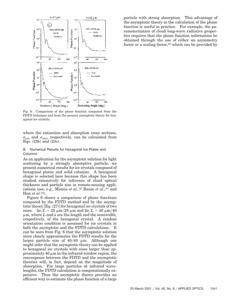
Figure 6 shows a comparison of phase functionscomputed by the FDTD method and by the asymp-totic theory @Eq. ~27!# for hexagonal ice crystals of twoizes: 2ayL 5 25 mmy25 mm and 2ayL 5 40 mmy40
mm, where L and a are the length and the semiwidth,respectively, of the hexagonal crystal. A randomorientation condition is assumed for ice crystals inboth the asymptotic and the FDTD calculations. Itcan be seen from Fig. 6 that the asymptotic solutionmore closely approximates the FDTD results for thelarger particle size of 40y40 mm. Although one
ight infer that the asymptotic theory can be appliedo hexagonal ice crystals with sizes larger than ap-roximately 40 mm in the infrared window region, theonvergence between the FDTD and the asymptoticheories will, in fact, depend on the magnitude ofbsorption. For large particles at infrared wave-engths, the FDTD calculation is computationally ex-ensive. Thus the asymptotic theory provides anfficient way to estimate the phase function of a large
Fig. 6. Comparison of the phase function computed from theFDTD technique and from the present asymptotic theory for hex-agonal ice crystals.
article with strong absorption. This advantage ofhe asymptotic theory in the calculation of the phaseunction is useful in practice. For example, the pa-ameterization of cloud long-wave radiative proper-ies requires that the phase function information bebtained through the use of either an asymmetryactor or a scaling factor,35 which can be provided by
20 March 2001 y Vol. 40, No. 9 y APPLIED OPTICS 1541
iaacsestcso
ir
1
the asymptotic theory efficiently and accurately whenthe particle size is larger than approximately 40 mm.
Figure 7 shows a comparison of the single-scattering albedo computed from the FDTD and theasymptotic theories. In the figure, the results com-puted for the equivalent spheres are also shown.Following Mitchell et al.,36 Fu et al.,37 and Grenfelland Warren,38 we define the radius of the equivalentsphere for a hexagonal particle as follows:
re 534
VA
532
Î3y2aL
Î3y2a 1 L, (30)
where V is the volume of nonspherical particles and As the projected area. Because strong absorption isssumed in the computation of the single-scatteringlbedo in the asymptotic theory, the result does nothange with the variation of particle size. As a re-ult, the asymptotic theory can lead to substantialrrors in the single-scattering albedo calculation formall and moderate particle sizes. However, fromhe trend of the FDTD solution, it is expected thatonvergence between the FDTD and asymptotic re-ults can be reached when the particle size is of therder of 200. Approaches developed by Fu et al.,37
Mitchell,39 and Baran and Havemann40 can be usedto overcome the shortcomings of the asymptotic the-ory in calculating single-scattering albedo. It
542 APPLIED OPTICS y Vol. 40, No. 9 y 20 March 2001
should be pointed out that these approaches cannotprovide the information for the phase function. Forthis reason, a combination of these approaches ~forthe computation of single-scattering albedo! with theasymptotic theory ~for the computation of phase func-tion! would be more useful in practice.
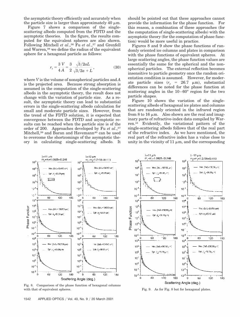
Figures 8 and 9 show the phase functions of ran-domly oriented ice columns and plates in comparisonwith the phase functions of equivalent spheres. Atlarge scattering angles, the phase function values areessentially the same for the spherical and the non-spherical particles. The external reflection becomesinsensitive to particle geometry once the random ori-entation condition is assumed. However, for moder-ate particle sizes ~re 5 26.7 mm!, substantialdifferences can be noted for the phase function atscattering angles in the 10–60° region for the twoparticle shapes.
Figure 10 shows the variation of the single-scattering albedo of hexagonal ice plates and columnsthat are randomly oriented in the infrared regionfrom 8 to 16 mm. Also shown are the real and imag-nary parts of refractive-index data compiled by War-en.41 Evidently, the variational pattern of the
single-scattering albedo follows that of the real partof the refractive index. As we have mentioned, thereal part of the refractive index has a value close tounity in the vicinity of 11 mm, and the corresponding
Fig. 8. Comparison of the phase function of hexagonal columnswith that of equivalent spheres.
Fig. 9. As for Fig. 8 but for hexagonal plates.
ta
imaginary part is substantially large. Near 11 mm,he extinction of incident radiation is dominated bybsorption and is known as the Christiansen effect.23
As a result, a minimum is noted in the single-scattering albedo. From Fig. 10 it can also be seenthat the single-scattering albedo for hexagonal par-
Fig. 10. Comparison of the single-scattering albedo value
Fig. 11. Incident and scattering geometri
ticles is larger than for spheres. This property hasbeen noted in a comparison of the FDTD solutionwith the equivalent spherical results that are shownin Fig. 7.
It is a common practice to assume that ice crystalsare randomly oriented in space. However, in the
puted for hexagonal ice crystals and equivalent spheres.
an ice crystal with preferred orientation.
s com
es for
20 March 2001 y Vol. 40, No. 9 y APPLIED OPTICS 1543
cztfeh
awafpfpaosti
indi
tsctitnd
ptrpcF
prs
1
atmosphere specific orientations are preferred forlarge plates and columns. For plates in an environ-ment of a low Reynolds number, such as in a typicalmid-latitude cirrus cloud, the a axis ~the hexagonalasymmetric axis! of the particle tends to face verti-ally, whereas the c axis tends to be oriented hori-ontally. In other words, the crystals tend to alignhemselves so as to reach a stable state in the crystalalling process. The effect of preferred particle ori-ntation on the phase function at visible wavelengthsas been discussed by Takano and Liou42 and Rock-
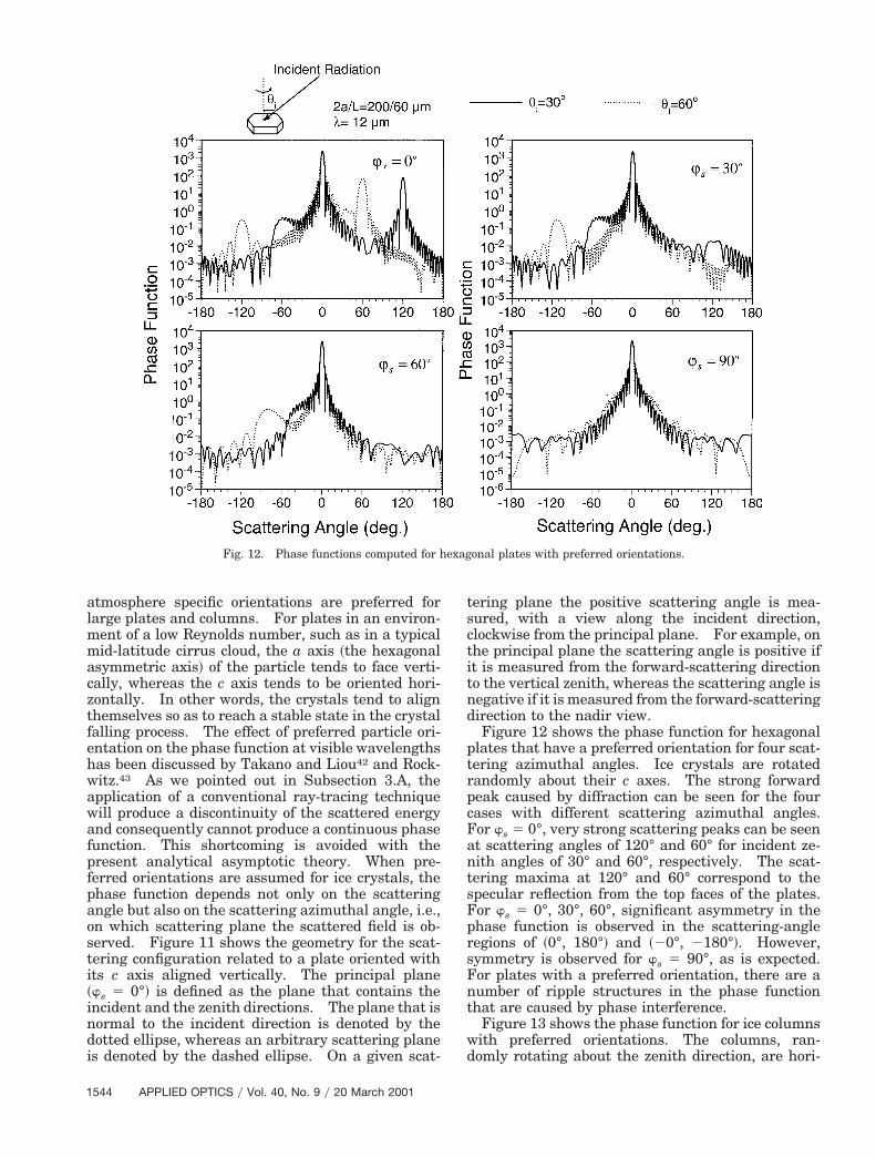
witz.43 As we pointed out in Subsection 3.A, thepplication of a conventional ray-tracing techniqueill produce a discontinuity of the scattered energynd consequently cannot produce a continuous phaseunction. This shortcoming is avoided with theresent analytical asymptotic theory. When pre-erred orientations are assumed for ice crystals, thehase function depends not only on the scatteringngle but also on the scattering azimuthal angle, i.e.,n which scattering plane the scattered field is ob-erved. Figure 11 shows the geometry for the scat-ering configuration related to a plate oriented withts c axis aligned vertically. The principal plane
~ws 5 0°! is defined as the plane that contains thencident and the zenith directions. The plane that isormal to the incident direction is denoted by theotted ellipse, whereas an arbitrary scattering planes denoted by the dashed ellipse. On a given scat-
Fig. 12. Phase functions computed for h
544 APPLIED OPTICS y Vol. 40, No. 9 y 20 March 2001
ering plane the positive scattering angle is mea-ured, with a view along the incident direction,lockwise from the principal plane. For example, onhe principal plane the scattering angle is positive ift is measured from the forward-scattering directiono the vertical zenith, whereas the scattering angle isegative if it is measured from the forward-scatteringirection to the nadir view.Figure 12 shows the phase function for hexagonal
lates that have a preferred orientation for four scat-ering azimuthal angles. Ice crystals are rotatedandomly about their c axes. The strong forwardeak caused by diffraction can be seen for the fourases with different scattering azimuthal angles.or ws 5 0°, very strong scattering peaks can be seen
at scattering angles of 120° and 60° for incident ze-nith angles of 30° and 60°, respectively. The scat-tering maxima at 120° and 60° correspond to thespecular reflection from the top faces of the plates.For ws 5 0°, 30°, 60°, significant asymmetry in the
hase function is observed in the scattering-angleegions of ~0°, 180°! and ~20°, 2180°!. However,ymmetry is observed for ws 5 90°, as is expected.
For plates with a preferred orientation, there are anumber of ripple structures in the phase functionthat are caused by phase interference.
Figure 13 shows the phase function for ice columnswith preferred orientations. The columns, ran-domly rotating about the zenith direction, are hori-
onal plates with preferred orientations.
exag
Fig. 13. As for Fig. 12 but for columns.
Fig. 14. Single-scattering albedo for ice crystals that have preferred orientations compared with the results for randomly orientedcrystals.
20 March 2001 y Vol. 40, No. 9 y APPLIED OPTICS 1545

apseAe
cCppatatfipest
t
o
tanreffirr
sbietddpdnbga
NfitD0
1
zontally oriented but rotate randomly about their cxes. The ripple structure of plates caused by thehase interference as noted for Fig. 12 is largelymoothed out for oriented columns because the ori-ntation of the particles in columns is more random.s for plates, the specular reflection feature is appar-nt when ws 5 0°.Figure 14 shows the single-scattering albedo that
orresponds to the phase functions in Figs. 12 and 13.ompared with the results for randomly orientedarticles, the single scattering for both orientedlates and columns is smaller if the incident zenithngle is less than approximately 60°. For plates,here is a pronounced peak in the single-scatteringlbedo at the incident zenith of 70°. This peak ishought to be due to the external reflection for the topace of the plate that is increasing with increasingncident zenith angle. However, when this angle ap-roaches 90°, the projected area of the top face isssentially zero, and the external reflection from theide faces, along with diffraction, dominates the scat-ered field.
4. Summary and Conclusions
An asymptotic solution in an analytical format forderiving the scattering properties of a general poly-hedral particle with strong absorption has been pre-sented. For scattering calculations involvingnonspherical particles such as aerosols and ice crys-tals, we showed that the transverse-wave condition isnot applicable to the refracted electromagnetic wavewhen absorption is involved. In the geometrical-optics solution for wave propagation in an absorbingdielectric medium, either the TM wave condition ~i.e.,when the magnetic field of the refracted wave istransverse to the wave direction! or the TE wavecondition ~i.e., when the electric field is transverse tohe propagating direction of the wave! can be as-
sumed for the refracted wave to satisfy the electro-magnetic boundary condition. The wave modeassumed for the refracted wave affects both reflectionand refraction coefficients. As a result, a nonuniquesolution for these coefficients is derived from the elec-tromagnetic boundary condition. Through compar-ison of the asymptotic geometrical-optics solution andresults determined from Mie theory for absorbingspheres, it has been shown that TM and TE wavemodes should be applied to two polarized componentsthat are parallel and perpendicular, respectively, tothe incident plane. In this study we have identifiedthe appropriate solution for the Fresnel reflectioncoefficients in the ray-tracing calculation. We pre-sented the 3 3 2 refraction or transmission matrixthat completely accounts for the inhomogeneity of therefracted wave in an absorbing medium. Based onthe Fresnel coefficients for an absorbing medium, wederived the asymptotic solution in an analytical for-mat for the scattering properties of a general polyhe-dral particle. Numerical results were presented forhexagonal plates and columns with both preferredand random orientation. The asymptotic theoryproduces reasonable accuracy in the phase function
546 APPLIED OPTICS y Vol. 40, No. 9 y 20 March 2001
calculations in the infrared window region ~wave-lengths near 10 mm! if the particle size is of the orderf 40-mm diameter or larger.However, because strong absorption is assumed in
he computation of the single-scattering albedo in thesymptotic theory, the single-scattering albedo doesot change with variation of the particle size. As aesult, the asymptotic theory can lead to substantialrrors in the computation of single-scattering albedoor small and moderate particle sizes. However,rom a comparison of results with the FDTD solutiont is expected that a convergence between the FDTDesults and the asymptotic theory results will beeached when the particle size approaches 200 mm.
For two infrared wavelengths, 11 and 12 mm, wehowed that the phase function at side-scattering andackscattering angles is insensitive to particle shapef random orientation is assumed. For preferred ori-ntations, however, we showed that the phase func-ions for plates and columns are significantlyifferent. Additionally, when a preferred two-imensional orientation condition is assumed, thehase function is observed to have a strong depen-ence on the scattering azimuthal angle. Moreover,umerical results show that the single-scattering al-edo has a strong dependence on the inclination an-le of incident radiation with respect to the rotatingxis for the preferred particle orientations.
This research has been supported by a grant fromASA’s MODIS project and partially by the U.S. Of-ce of Naval Research and the Atmospheric Radia-ion Measurement program sponsored by the U.S.epartment of Energy under contract DE-AI02-0ER62901.
References1. M. I. Mishchenko, J. W. Hovenier, and L. D. Travis, Light
Scattering by Nonspherical Particles: Theory, Measurements,and Applications ~Academic, San Diego, Calif., 1999!.
2. E. M. Purcell and C. R. Pennypacker, “Scattering and absorp-tion of light by nonspherical dielectric grains,” Astrophys. J.186, 705–714 ~1973!.
3. B. T. Draine and P. J. Flatau, “Discrete-dipole approximationfor light calculations,” J. Opt. Soc. Am. A 11, 1491–1499 ~1994!.
4. P. Yang and K. N. Liou, “Finite-difference time domain methodfor light scattering by small ice crystals in three-dimensionalspace,” J. Opt. Soc. Am. A 13, 2072–2085 ~1996!.
5. W.-B. Sun, Q. Fu, and Z. Chen, “Finite-difference time-domainsolution of light scattering by dielectric particles with a per-fectly matched layer absorbing boundary condition,” Appl. Opt.38, 3141–3151 ~1999!.
6. G. Mie, “Beitrage zur Optik truber Medien, speziell kolloidalerMetallosungen,” Ann. Phys. ~Leipzig! 25, 377–445 ~1908!.
7. S. Asano and M. Sato, “Light scattering by randomly orientedspheroidal particles,” Appl. Opt. 19, 962–974 ~1980!.
8. V. G. Farafonov, N. V. Voshchinnikov, and V. V. Somsikov,“Light scattering by a core-mantle spheroidal particle,” Appl.Opt. 35, 5412–5426 ~1996!.
9. M. I. Mishchenko, “Light scattering by randomly oriented ax-ially symmetric particles,” J. Opt. Soc. Am. A 8, 871–882~1991!.
10. M. I. Mishchenko, “Light scattering by size-shape distributionsof randomly oriented axially symmetric particles of a size com-parable to a wavelength,” Appl. Opt. 32, 623–625 ~1993!.

11. M. I. Mishchenko and A. Macke, “How big should hexagonal
1
1
29. A. Macke, M. I. Mishchenko, K. Muinonen, and B. E. Carlson,
ice crystals be to produce halos?” Appl. Opt. 38, 1626–1629~1999!.12. Y. Takano and K. N. Liou, “Solar radiative transfer in cirrusclouds. I. Single-scattering and optical properties of hexag-onal ice crystals,” J. Atmos. Sci. 46, 3–19 ~1989!.
3. A. Macke, “Scattering of light by polyhedral ice crystals,” Appl.Opt. 32, 2780–2788 ~1993!.
4. J. A. Lock, “Ray scattering by an arbitrarily oriented spheroid.I. Diffraction and specular reflection. II. Transmissionand cross-polarization effects,” Appl. Opt. 35, 500–531 ~1996!.
15. K. Muinonen, K. Lumme, J. Peltoniemi, and W. M. Irvine,“Light scattering by randomly oriented crystals,” Appl. Opt.28, 3051–3060 ~1989!.
16. A. Arking and J. D. Childs, “Retrieval of cloud cover parame-ters from multispectral satellite images,” J. Clim. Appl. Me-teorol. 24, 322–333 ~1985!.
17. M. D. King, Y. J. Kaufman, W. P. Menzel, and D. Tanre,“Remote sensing of cloud, aerosol, and water vapor propertiesfrom the Moderate Resolution Imaging Spectrometer ~MO-DIS!,” IEEE Trans. Geosci. Remote Sens. 30, 2–26 ~1992!.
18. W. L. Smith, H. E. Revercomb, R. O. Knuteson, F. A. Best, R.Dedecker, H. B. Howell, and H. M. Woolf, “Cirrus cloud prop-erties derived from high spectral resolution infrared spectrom-etry during FIRE II. I. The high resolution interferometersounder ~HIS! systems,” J. Atmos. Sci. 52, 4238–4245 ~1995!.
19. J. A. Stratton, Electromagnetic Theory ~McGraw-Hill, NewYork, 1941!.
20. M. Born and E. Wolf, Principles of Optics ~Pergamon, Oxford,1970!.
21. J. Zhang and L. Xu, “Light scattering by absorbing hexagonalice crystals in cirrus clouds,” Appl. Opt. 34, 5867–5874 ~1995!.
22. P. Yang and K. N. Liou, “Light scattering by hexagonal icecrystals: comparison of finite-difference time domain andgeometric optics models,” J. Opt. Soc. Am. A 12, 162–176~1995!.
23. W. P. Arnott, Y. Y. Dong, and J. Hallett, “Extinction efficiencyin the infrared ~2–18 mm! of laboratory ice clouds: observa-tions of scattering minima in the Christiansen bands of ice,”Appl. Opt. 34, 541–551 ~1995!.
24. C. F. Bohren and D. R. Huffman, Absorption and Scattering ofLight by Small Particles ~Wiley, New York, 1983!.
25. H. C. van de Hulst, Light Scattering by Small Particles ~Wiley,New York, 1957!.
26. P. Yang and K. N. Liou, “Single-scattering properties of com-plex ice crystals in terrestrial atmosphere,” Contrib. Atmos.Phys. 71, 223–248 ~1998!.
27. W. J. Wiscombe, “Improved Mie scattering algorithms,” Appl.Opt. 19, 1505–1509 ~1980!.
28. K. N. Liou and J. E. Hansen, “Intensity and polarization forsingle scattering by polydisperse spheres: a comparison ofray optics and Mie theory,” J. Atmos. Sci. 28, 995–1004 ~1971!.
“Scattering of light by large nonspherical particles: ray-tracing approximation versus T-matrix method,” Opt. Lett. 20,1934–1936 ~1995!.
30. M. I. Mishchenko and A. Macke, “Incorporation of physicaloptics effect and computation of the Legendre expansion forray-tracing phase functions involving d-function transmis-sion,” J. Geophys. Res. 103, 1799–1805 ~1998!.
31. P. Yang and K. N. Liou, “Light scattering by hexagonal icecrystals: solution by a ray-by-ray integration algorithm,” J.Opt. Soc. Am. A 14, 2278–2289 ~1997!.
32. P. Minnis, K. N. Liou, and Y. Takano, “Inference of cirrus cloudproperties using satellite-observed visible and infrared radi-ances. I. Parameterization of radiance fields,” J. Atmos.Sci. 50, 1279–1304 ~1993!.
33. B. A. Baum, R. F. Arduini, B. A. Wielicki, P. Minnis, and S.-C.Tsay, “Multilevel cloud retrieval using multispectral HIRS andAVHRR data: nighttime oceanic analysis,” J. Geophys. Res.99, 5499–5514 ~1994!.
34. Q. Han, W. B. Rossow, J. Chou, K-S. Kuo, and R. M. Welch,“The effect of aspect ratio and surface roughness on satelliteretrieval of ice-cloud properties,” J. Quant. Spectrosc. Radiat.Transfer 63, 559–583 ~1999!.
35. M.-D. Chou, K-T. Lee, S.-C. Tsay, and Q. Fu, “Parameteriza-tion for cloud longwave scattering for use in atmosphere mod-els,” J. Climate 12, 159–169 ~1999!.
36. D. L. Mitchell, A. Macke, and Y. Liu, “Modeling cirrus clouds.II. Treatment of radiative properties,” J. Atmos. Sci. 53,2967–2988 ~1996!.
37. Q. Fu, P. Yang, and W. B. Sun, “An accurate parameterizationof the infrared radiative properties of cirrus clouds for climatemodels,” J. Climate 11, 2223–2237 ~1998!.
38. T. C. Grenfell and S. G. Warren, “Representation of a non-spherical ice particle by a collection of independent spheres forscattering and absorption of radiation,” J. Geophys. Res. 104,31,697–31,709 ~1999!.
39. D. L. Mitchell, “Parameterization of the Mie extinction andabsorption coefficients for water clouds,” J. Atmos. Sci. 57,1311–1326 ~2000!.
40. A. J. Baran and S. Havemann, “Rapid computation of theoptical properties of hexagonal columns using complex angularmomentum theory,” J. Quant. Spectrosc. Radiat. Transfer 63,499–519 ~1999!.
41. S. Warren, “Optical constants of ice from the ultraviolet to themicrowave,” Appl. Opt. 23, 1206–1225 ~1984!.
42. Y. Takano and K. N. Liou, “Radiative transfer in cirrus clouds.II. Theory and computation of multiple scattering in ananisotropic medium,” J. Atmos. Sci. 46, 20–36 ~1989!.
43. K.-D. Rockwitz, “Scattering properties of horizontally orientedice crystal columns in cirrus clouds,” Appl. Opt. 28, 4103–4110~1989!.
20 March 2001 y Vol. 40, No. 9 y APPLIED OPTICS 1547