Assessment of the Condition of Anilox Rollers - MDPI
12
coatings Article Assessment of the Condition of Anilox Rollers Arnas Savickas, Rimantas Stonkus * , Eugenijus Jurkonis and Igor Iljin Citation: Savickas, A.; Stonkus, R.; Jurkonis, E.; Iljin, I. Assessment of the Condition of Anilox Rollers. Coatings 2021, 11, 1301. https://doi.org/ 10.3390/coatings11111301 Academic Editor: Andreas Rosenkranz Received: 14 September 2021 Accepted: 24 October 2021 Published: 27 October 2021 Publisher’s Note: MDPI stays neutral with regard to jurisdictional claims in published maps and institutional affil- iations. Copyright: © 2021 by the authors. Licensee MDPI, Basel, Switzerland. This article is an open access article distributed under the terms and conditions of the Creative Commons Attribution (CC BY) license (https:// creativecommons.org/licenses/by/ 4.0/). Department of Mechatronics, Robotics and Digital Manufacturing, Vilnius Gediminas Technical University, J. Basanavicius Str. 28, 03224 Vilnius, Lithuania; [email protected] (A.S.); [email protected] (E.J.); [email protected] (I.I.) * Correspondence: [email protected] Abstract: To produce high-quality prints using flexographic printing technology, it is important, among other factors, how accurately and consistently the ink is delivered to the printing plate, and, from there, onto the printed material. This function is performed by anilox rollers. The aim of this research is to investigate the condition of anilox rollers in printing houses in the Baltic states. The study evaluated the wear and cell clogging of anilox rollers. The dependency of clogging on the cell size, as well as the dependency of wear on the cell size (i.e., change in cell volume) and quantity of doctor blades, was investigated. In addition, the uniformity of cell clogging and wear on the surface of the anilox roller was evaluated. Studies have shown that more than half of the anilox rollers in printing houses are not washed properly; higher line screen anilox rollers tend to become more clogged, and it is important to take measurements at more than three locations to assess the reliability of more worn rollers. Keywords: anilox roller; flexography; clogging; wear; cells engraving; ink transfer 1. Introduction Continual technological advancement, the ability to print with wide range of inks on different substrates, high-speed printing, and other advantages in flexography [1,2] have led to the wide application of this technology in the packaging industry [3] and graphic arts, as well as in the application of printed electronics [4], different functional devices [5,6], such as polymer solar cells [7], or the ability to print micro-scale conductive networks [8]. Flexography is a rotary direct-printing process, using a flexible relief printing plate (made from a photopolymer material or elastomer) that transfers low-viscosity printing inks to the substrate (Figure 1). The printing plate is mounted onto the plate cylinder (usually referred to as the printing cylinder) using a suitable mounting adhesive tape, with defined height and compressibility. The ink usually comes from an ink supply chamber using an ink pump. It is transferred on a metering roller called an “anilox”, and doctor blades are used to remove excess ink from the non-engraved surface of the anilox roller. The amount of ink transferred to the anilox roller is dependent on the anilox cell volume (determined itself by the size and frequency of the engraved cells) [1,9]. There are many factors that affect flexographic print quality [10], and a large variety of research has been conducted in this field. New innovations in flexography expand the possibilities for further improvement in quality, and for achieving this with less effort. Nevertheless, it is necessary to know the effects of different press parameters, such as printing pressure, temperature, and substrates, on print quality [11]. A pressure setting is critical in the flexographic process to promote good dots, and to prevent halo and control dot gain. The pressure between the printing plate and impression cylinder has the most significant influence on mechanical dot deformation (expansion and barrelling). Valdec et al. [12] studied how the various platemaking processes affect the dot geometry, on the basis of the influence of the most important variable parameters of flexographic printing. Folea et al. [13] focused on successive Pareto analyses, used to uncover solutions Coatings 2021, 11, 1301. https://doi.org/10.3390/coatings11111301 https://www.mdpi.com/journal/coatings
-
Upload
khangminh22 -
Category
Documents
-
view
1 -
download
0
Transcript of Assessment of the Condition of Anilox Rollers - MDPI
coatings
Article
Assessment of the Condition of Anilox Rollers
Arnas Savickas, Rimantas Stonkus * , Eugenijus Jurkonis and Igor Iljin
�����������������
Citation: Savickas, A.; Stonkus, R.;
Jurkonis, E.; Iljin, I. Assessment of the
Condition of Anilox Rollers. Coatings
2021, 11, 1301. https://doi.org/
10.3390/coatings11111301
Academic Editor: Andreas
Rosenkranz
Received: 14 September 2021
Accepted: 24 October 2021
Published: 27 October 2021
Publisher’s Note: MDPI stays neutral
with regard to jurisdictional claims in
published maps and institutional affil-
iations.
Copyright: © 2021 by the authors.
Licensee MDPI, Basel, Switzerland.
This article is an open access article
distributed under the terms and
conditions of the Creative Commons
Attribution (CC BY) license (https://
creativecommons.org/licenses/by/
4.0/).
Department of Mechatronics, Robotics and Digital Manufacturing, Vilnius Gediminas Technical University,J. Basanavicius Str. 28, 03224 Vilnius, Lithuania; [email protected] (A.S.);[email protected] (E.J.); [email protected] (I.I.)* Correspondence: [email protected]
Abstract: To produce high-quality prints using flexographic printing technology, it is important,among other factors, how accurately and consistently the ink is delivered to the printing plate, and,from there, onto the printed material. This function is performed by anilox rollers. The aim of thisresearch is to investigate the condition of anilox rollers in printing houses in the Baltic states. Thestudy evaluated the wear and cell clogging of anilox rollers. The dependency of clogging on the cellsize, as well as the dependency of wear on the cell size (i.e., change in cell volume) and quantityof doctor blades, was investigated. In addition, the uniformity of cell clogging and wear on thesurface of the anilox roller was evaluated. Studies have shown that more than half of the aniloxrollers in printing houses are not washed properly; higher line screen anilox rollers tend to becomemore clogged, and it is important to take measurements at more than three locations to assess thereliability of more worn rollers.
Keywords: anilox roller; flexography; clogging; wear; cells engraving; ink transfer
1. Introduction
Continual technological advancement, the ability to print with wide range of inks ondifferent substrates, high-speed printing, and other advantages in flexography [1,2] haveled to the wide application of this technology in the packaging industry [3] and graphicarts, as well as in the application of printed electronics [4], different functional devices [5,6],such as polymer solar cells [7], or the ability to print micro-scale conductive networks [8].
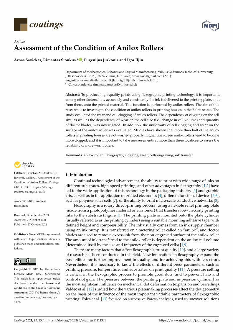
Flexography is a rotary direct-printing process, using a flexible relief printing plate(made from a photopolymer material or elastomer) that transfers low-viscosity printinginks to the substrate (Figure 1). The printing plate is mounted onto the plate cylinder(usually referred to as the printing cylinder) using a suitable mounting adhesive tape, withdefined height and compressibility. The ink usually comes from an ink supply chamberusing an ink pump. It is transferred on a metering roller called an “anilox”, and doctorblades are used to remove excess ink from the non-engraved surface of the anilox roller.The amount of ink transferred to the anilox roller is dependent on the anilox cell volume(determined itself by the size and frequency of the engraved cells) [1,9].
There are many factors that affect flexographic print quality [10], and a large varietyof research has been conducted in this field. New innovations in flexography expand thepossibilities for further improvement in quality, and for achieving this with less effort.Nevertheless, it is necessary to know the effects of different press parameters, such asprinting pressure, temperature, and substrates, on print quality [11]. A pressure settingis critical in the flexographic process to promote good dots, and to prevent halo andcontrol dot gain. The pressure between the printing plate and impression cylinder hasthe most significant influence on mechanical dot deformation (expansion and barrelling).Valdec et al. [12] studied how the various platemaking processes affect the dot geometry,on the basis of the influence of the most important variable parameters of flexographicprinting. Folea et al. [13] focused on successive Pareto analyses, used to uncover solutions
Coatings 2021, 11, 1301. https://doi.org/10.3390/coatings11111301 https://www.mdpi.com/journal/coatings
Coatings 2021, 11, 1301 2 of 12
for problems which arise during the flexographic printing process. Havenko et al. [14]examined the test prints obtained at a flexographic proofer. The authors analysed theinfluence of the surface roughness of cardboard as a printing medium on the printingproperties of environmentally friendly inks, and they determined a comprehensive indexof print quality, which could ensure the prediction of the quality of printed products,and would make it possible to adjust the printing process if necessary. Gencoglu [15]investigated the influence of water-based and solvent-based ink viscosity on dot areaon overprinted coated and uncoated papers. The rheological properties of inks play asignificant role in the printing process [16]. Borbely et al. [17] investigated the influenceof some technological parameters (the printing pressure and different types of inks andsubstrates) on print quality, with an emphasis on the pressure between the plate cylinderand the substrate on the impression cylinder. Lipiak [18] determined a methodology forassessing key factors that affect the quality and efficiency of a flexographic printing process.Bould [19] quantified the combined effects of process parameters on UV ink transfer andprint quality in flexographic printing. Morgan et al. [20] assessed the impact of ink elasticityon print uniformity.
Coatings 2021, 11, x FOR PEER REVIEW 2 of 12
Folea et al. [13] focused on successive Pareto analyses, used to uncover solutions for prob-lems which arise during the flexographic printing process. Havenko et al. [14] examined the test prints obtained at a flexographic proofer. The authors analysed the influence of the surface roughness of cardboard as a printing medium on the printing properties of environmentally friendly inks, and they determined a comprehensive index of print qual-ity, which could ensure the prediction of the quality of printed products, and would make it possible to adjust the printing process if necessary. Gencoglu [15] investigated the in-fluence of water-based and solvent-based ink viscosity on dot area on overprinted coated and uncoated papers. The rheological properties of inks play a significant role in the print-ing process [16]. Borbely et al. [17] investigated the influence of some technological pa-rameters (the printing pressure and different types of inks and substrates) on print qual-ity, with an emphasis on the pressure between the plate cylinder and the substrate on the impression cylinder. Lipiak [18] determined a methodology for assessing key factors that affect the quality and efficiency of a flexographic printing process. Bould [19] quantified the combined effects of process parameters on UV ink transfer and print quality in flexo-graphic printing. Morgan et al. [20] assessed the impact of ink elasticity on print uni-formity.
Figure 1. Schematic description of the flexographic printing process.
Among other factors affecting the high-quality prints in flexography is the controlled transfer of ink to the substrate. In flexographic printing, the anilox roller is an essential component of the ink system [21] that transfers the appropriate ink film thickness onto the printing plate, and from there ink is transferred onto the printed material. Ink film thickness is the volume of ink that transfers to the printing plates, and determines colour strength and print quality. The required amount of ink transferred to the substrate de-pends on type of substrate, the type and viscosity of inks, the type of printing plates, and other factors. The amount of ink transferred by the anilox roller depends on the cell ge-ometry of the anilox roll, and there are three main cell characteristics influencing ink trans-fer: cell volume, line screen, and angle of the cells [2,21–23]. Little research related to the anilox roller has been conducted. Bould et al. [24] analysed the effect of pressure changes on print quality for different anilox specifications and line rulings on the plate. The au-thors found that the ink-carrying volume of the cells of the anilox roll have the greatest influence on solid density and halftone dot formation; however, the geometrical charac-teristics of the cells were also shown to have an effect. An initial increase in the pressure within the printing nip resulted in a significant rise in both solid density and tone gain, due to improved ink transfer from the plate to the substrate. The rate of increase of half-tone density was found to be reduced as pressure increased, which was attributed to the ink approaching its maximum capability for spreading on the substrate. Blagodir et al.
Figure 1. Schematic description of the flexographic printing process.
Among other factors affecting the high-quality prints in flexography is the controlledtransfer of ink to the substrate. In flexographic printing, the anilox roller is an essentialcomponent of the ink system [21] that transfers the appropriate ink film thickness ontothe printing plate, and from there ink is transferred onto the printed material. Ink filmthickness is the volume of ink that transfers to the printing plates, and determines colourstrength and print quality. The required amount of ink transferred to the substrate dependson type of substrate, the type and viscosity of inks, the type of printing plates, and otherfactors. The amount of ink transferred by the anilox roller depends on the cell geometry ofthe anilox roll, and there are three main cell characteristics influencing ink transfer: cellvolume, line screen, and angle of the cells [2,21–23]. Little research related to the aniloxroller has been conducted. Bould et al. [24] analysed the effect of pressure changes onprint quality for different anilox specifications and line rulings on the plate. The authorsfound that the ink-carrying volume of the cells of the anilox roll have the greatest influenceon solid density and halftone dot formation; however, the geometrical characteristics ofthe cells were also shown to have an effect. An initial increase in the pressure withinthe printing nip resulted in a significant rise in both solid density and tone gain, due toimproved ink transfer from the plate to the substrate. The rate of increase of halftonedensity was found to be reduced as pressure increased, which was attributed to the inkapproaching its maximum capability for spreading on the substrate. Blagodir et al. [25]analysed the ink-transfer process during flexographic printing. The authors performed anumerical simulation, and estimated the influence of the anilox cavity shape, ink viscosity,
Coatings 2021, 11, 1301 3 of 12
and printing plate contact angles on the ink-transfer ratio. Deganello et al. [9] analysedthe production of micro-scale conductive networks at various anilox volumes. Cherry [22]investigated the ink-release characteristics of anilox rolls.
Despite advanced anilox manufacturing technologies, problems with the unpre-dictable reduction in the amount of ink during the operation of anilox rollers still remain.This is due to the improper maintenance of the anilox rollers, as well as different practicesof inspecting ink transfer [26–28]. Anilox rollers wear and plug during operation, and thisleads to a reduced transfer of ink [29], resulting in lower optical density (loss in colourstrength) of the prints. However, there are few studies that analyse the condition of aniloxrollers; there is a lack of research that analyses what influences anilox roller cell cloggingand cell wear, and how it does so [29,30].
The research goal of this paper was to evaluate the quality of anilox rollers (thesurface wear and clogging of the cells) in working printing houses in the Baltic states.Different types of ink (solvent-based, water-based, and UV inks), as well as differentviscosities of inks, were used in printing houses involved in the study. This publication isthe continuation of a previously initiated study focussed on anilox roller cell clogging [30].
Improper maintenance of the anilox rollers increases the probability that the cells willmore quickly become clogged, the walls will wear out, and ink transfer will be reducedto such an extent that the optical density of the prints will be insufficient, and it will nolonger be possible to print quality printed products.
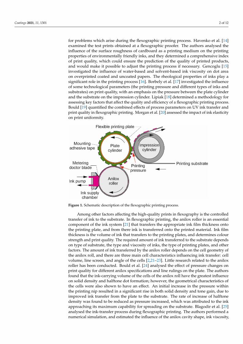
The condition of the anilox rollers worsens during operation due to the contaminationof the cells or wear of the cell walls, which leads to a decrease in the amount of inktransferred [26]. The main factors influencing the reduction of ink transfer is presented inFigure 2.
Coatings 2021, 11, x FOR PEER REVIEW 3 of 12
[25] analysed the ink-transfer process during flexographic printing. The authors per-formed a numerical simulation, and estimated the influence of the anilox cavity shape, ink viscosity, and printing plate contact angles on the ink-transfer ratio. Deganello et al. [9] analysed the production of micro-scale conductive networks at various anilox volumes. Cherry [22] investigated the ink-release characteristics of anilox rolls.
Despite advanced anilox manufacturing technologies, problems with the unpredict-able reduction in the amount of ink during the operation of anilox rollers still remain. This is due to the improper maintenance of the anilox rollers, as well as different practices of inspecting ink transfer [26–28]. Anilox rollers wear and plug during operation, and this leads to a reduced transfer of ink [29], resulting in lower optical density (loss in colour strength) of the prints. However, there are few studies that analyse the condition of anilox rollers; there is a lack of research that analyses what influences anilox roller cell clogging and cell wear, and how it does so [29,30].
The research goal of this paper was to evaluate the quality of anilox rollers (the sur-face wear and clogging of the cells) in working printing houses in the Baltic states. Differ-ent types of ink (solvent-based, water-based, and UV inks), as well as different viscosities of inks, were used in printing houses involved in the study. This publication is the con-tinuation of a previously initiated study focussed on anilox roller cell clogging [30].
Improper maintenance of the anilox rollers increases the probability that the cells will more quickly become clogged, the walls will wear out, and ink transfer will be reduced to such an extent that the optical density of the prints will be insufficient, and it will no longer be possible to print quality printed products.
The condition of the anilox rollers worsens during operation due to the contamina-tion of the cells or wear of the cell walls, which leads to a decrease in the amount of ink transferred [26]. The main factors influencing the reduction of ink transfer is presented in Figure 2.
Figure 2. Factors influencing the reduction of ink transfer.
To assess the change in the amount of ink transferred, the measured values are com-pared with the transfer values declared by the manufacturer. There is currently no inter-national standard for measuring the amount of ink transferred by anilox rollers, so the ink-transfer data of each manufacturer are different [27].
Figure 2. Factors influencing the reduction of ink transfer.
To assess the change in the amount of ink transferred, the measured values arecompared with the transfer values declared by the manufacturer. There is currently nointernational standard for measuring the amount of ink transferred by anilox rollers, so theink-transfer data of each manufacturer are different [27].
In practice, various methods and tools for estimating the amount of transferredink are used, and the accuracy of measurements is also influenced by the experience ofemployees. Studies have shown that the use of optical 3D microscopes, such as AniCAMand 3DQC, yielded the least divergent results in anilox roller ink-transfer measurements.The importance of the experience of the workers and the diameter of the rollers measured
Coatings 2021, 11, 1301 4 of 12
is not crucial, as long as the same instrument and results are not compared with othermeasurement methods [28].
The article’s main purpose is to evaluate the conditions of anilox roller surfaces usedin print houses in Baltic states. The suitability of the condition of the anilox rollers for atechnological printing process of acceptable quality is determined by several operationalparameters, the most important of which are the clogging of the cells, and the wear of thesurface of the roller.
2. Materials and Methods
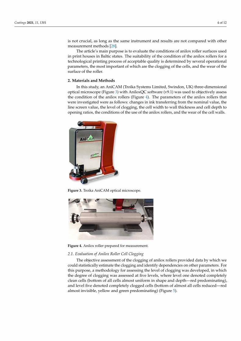
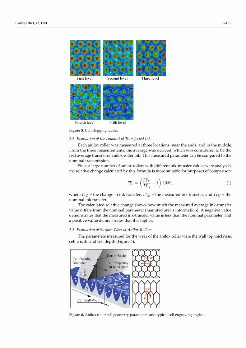
In this study, an AniCAM (Troika Systems Limited, Swindon, UK) three-dimensionaloptical microscope (Figure 3) with AniloxQC software (v9.1) was used to objectively assessthe condition of the anilox rollers (Figure 4). The parameters of the anilox rollers thatwere investigated were as follows: changes in ink transferring from the nominal value, theline screen value, the level of clogging, the cell width to wall thickness and cell depth toopening ratios, the conditions of the use of the anilox rollers, and the wear of the cell walls.
Coatings 2021, 11, x FOR PEER REVIEW 4 of 12
In practice, various methods and tools for estimating the amount of transferred ink are used, and the accuracy of measurements is also influenced by the experience of em-ployees. Studies have shown that the use of optical 3D microscopes, such as AniCAM and 3DQC, yielded the least divergent results in anilox roller ink-transfer measurements. The importance of the experience of the workers and the diameter of the rollers measured is not crucial, as long as the same instrument and results are not compared with other meas-urement methods [28].
The article’s main purpose is to evaluate the conditions of anilox roller surfaces used in print houses in Baltic states. The suitability of the condition of the anilox rollers for a technological printing process of acceptable quality is determined by several operational parameters, the most important of which are the clogging of the cells, and the wear of the surface of the roller.
2. Materials and Methods In this study, an AniCAM (Troika Systems Limited, Swindon, UK) three-dimensional
optical microscope (Figure 3) with AniloxQC software (v9.1) was used to objectively as-sess the condition of the anilox rollers (Figure 4). The parameters of the anilox rollers that were investigated were as follows: changes in ink transferring from the nominal value, the line screen value, the level of clogging, the cell width to wall thickness and cell depth to opening ratios, the conditions of the use of the anilox rollers, and the wear of the cell walls.
Figure 3. Troika AniCAM optical microscope.
Figure 4. Anilox roller prepared for measurement.
2.1. Evaluation of Anilox Roller Cell Clogging The objective assessment of the clogging of anilox rollers provided data by which we
could statistically estimate the clogging and identify dependencies on other parameters. For this purpose, a methodology for assessing the level of clogging was developed, in which the degree of clogging was assessed at five levels, where level one denoted com-pletely clean cells (bottom of all cells almost uniform in shape and depth—red predomi-nating), and level five denoted completely clogged cells (bottom of almost all cells re-duced—red almost invisible, yellow and green predominating) (Figure 5).
Figure 3. Troika AniCAM optical microscope.
Coatings 2021, 11, x FOR PEER REVIEW 4 of 12
In practice, various methods and tools for estimating the amount of transferred ink are used, and the accuracy of measurements is also influenced by the experience of em-ployees. Studies have shown that the use of optical 3D microscopes, such as AniCAM and 3DQC, yielded the least divergent results in anilox roller ink-transfer measurements. The importance of the experience of the workers and the diameter of the rollers measured is not crucial, as long as the same instrument and results are not compared with other meas-urement methods [28].
The article’s main purpose is to evaluate the conditions of anilox roller surfaces used in print houses in Baltic states. The suitability of the condition of the anilox rollers for a technological printing process of acceptable quality is determined by several operational parameters, the most important of which are the clogging of the cells, and the wear of the surface of the roller.
2. Materials and Methods In this study, an AniCAM (Troika Systems Limited, Swindon, UK) three-dimensional
optical microscope (Figure 3) with AniloxQC software (v9.1) was used to objectively as-sess the condition of the anilox rollers (Figure 4). The parameters of the anilox rollers that were investigated were as follows: changes in ink transferring from the nominal value, the line screen value, the level of clogging, the cell width to wall thickness and cell depth to opening ratios, the conditions of the use of the anilox rollers, and the wear of the cell walls.
Figure 3. Troika AniCAM optical microscope.
Figure 4. Anilox roller prepared for measurement.
2.1. Evaluation of Anilox Roller Cell Clogging The objective assessment of the clogging of anilox rollers provided data by which we
could statistically estimate the clogging and identify dependencies on other parameters. For this purpose, a methodology for assessing the level of clogging was developed, in which the degree of clogging was assessed at five levels, where level one denoted com-pletely clean cells (bottom of all cells almost uniform in shape and depth—red predomi-nating), and level five denoted completely clogged cells (bottom of almost all cells re-duced—red almost invisible, yellow and green predominating) (Figure 5).
Figure 4. Anilox roller prepared for measurement.
2.1. Evaluation of Anilox Roller Cell Clogging
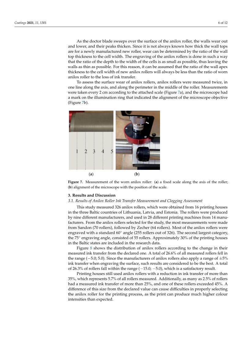
The objective assessment of the clogging of anilox rollers provided data by which wecould statistically estimate the clogging and identify dependencies on other parameters. Forthis purpose, a methodology for assessing the level of clogging was developed, in whichthe degree of clogging was assessed at five levels, where level one denoted completelyclean cells (bottom of all cells almost uniform in shape and depth—red predominating),and level five denoted completely clogged cells (bottom of almost all cells reduced—redalmost invisible, yellow and green predominating) (Figure 5).
Coatings 2021, 11, 1301 5 of 12Coatings 2021, 11, x FOR PEER REVIEW 5 of 12
Figure 5. Cell clogging levels.
2.2. Evaluation of the Amount of Transferred Ink Each anilox roller was measured at three locations: near the ends, and in the middle.
From the three measurements, the average was derived, which was considered to be the real average transfer of anilox roller ink. This measured parameter can be compared to the nominal transmission.
Since a large number of anilox rollers with different ink-transfer values were ana-lysed, the relative change calculated by this formula is more suitable for purposes of com-parison: 𝐼𝑇 = − 1 ∙ 100%, (1)
where 𝐼𝑇 = the change in ink transfer; 𝐼𝑇 = the measured ink transfer; and 𝐼𝑇 = the nominal ink transfer.
The calculated relative change shows how much the measured average ink-transfer value differs from the nominal parameter (manufacturer’s information). A negative value demonstrates that the measured ink-transfer value is less than the nominal parameter, and a positive value demonstrates that it is higher.
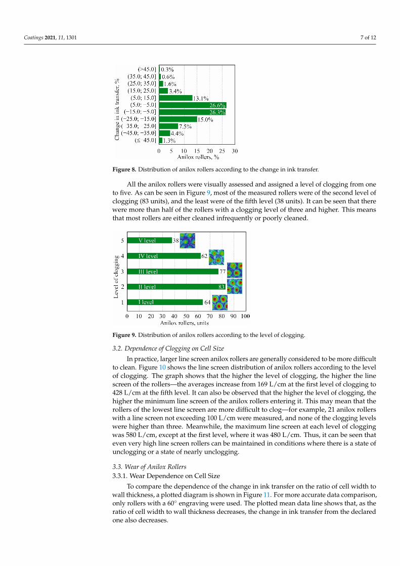
2.3. Evaluation of Surface Wear of Anilox Rollers The parameters measured for the wear of the anilox roller were the wall top thick-
ness, cell width, and cell depth (Figure 6).
Figure 6. Anilox roller cell geometry parameters and typical cell engraving angles.
Figure 5. Cell clogging levels.
2.2. Evaluation of the Amount of Transferred Ink
Each anilox roller was measured at three locations: near the ends, and in the middle.From the three measurements, the average was derived, which was considered to be thereal average transfer of anilox roller ink. This measured parameter can be compared to thenominal transmission.
Since a large number of anilox rollers with different ink-transfer values were analysed,the relative change calculated by this formula is more suitable for purposes of comparison:
ITC =
(ITMITN
− 1)·100%, (1)
where ITC = the change in ink transfer; ITM = the measured ink transfer; and ITN = thenominal ink transfer.
The calculated relative change shows how much the measured average ink-transfervalue differs from the nominal parameter (manufacturer’s information). A negative valuedemonstrates that the measured ink-transfer value is less than the nominal parameter, anda positive value demonstrates that it is higher.
2.3. Evaluation of Surface Wear of Anilox Rollers
The parameters measured for the wear of the anilox roller were the wall top thickness,cell width, and cell depth (Figure 6).
Coatings 2021, 11, x FOR PEER REVIEW 5 of 12
Figure 5. Cell clogging levels.
2.2. Evaluation of the Amount of Transferred Ink Each anilox roller was measured at three locations: near the ends, and in the middle.
From the three measurements, the average was derived, which was considered to be the real average transfer of anilox roller ink. This measured parameter can be compared to the nominal transmission.
Since a large number of anilox rollers with different ink-transfer values were ana-lysed, the relative change calculated by this formula is more suitable for purposes of com-parison: 𝐼𝑇 = − 1 ∙ 100%, (1)
where 𝐼𝑇 = the change in ink transfer; 𝐼𝑇 = the measured ink transfer; and 𝐼𝑇 = the nominal ink transfer.
The calculated relative change shows how much the measured average ink-transfer value differs from the nominal parameter (manufacturer’s information). A negative value demonstrates that the measured ink-transfer value is less than the nominal parameter, and a positive value demonstrates that it is higher.
2.3. Evaluation of Surface Wear of Anilox Rollers The parameters measured for the wear of the anilox roller were the wall top thick-
ness, cell width, and cell depth (Figure 6).
Figure 6. Anilox roller cell geometry parameters and typical cell engraving angles. Figure 6. Anilox roller cell geometry parameters and typical cell engraving angles.
Coatings 2021, 11, 1301 6 of 12
As the doctor blade sweeps over the surface of the anilox roller, the walls wear outand lower, and their peaks thicken. Since it is not always known how thick the wall topsare for a newly manufactured new roller, wear can be determined by the ratio of the walltop thickness to the cell width. The engraving of the anilox rollers is done in such a waythat the ratio of the depth to the width of the cells is as small as possible, thus leaving thewalls as thin as possible. For this reason, it can be assumed that the ratio of the wall apexthickness to the cell width of new anilox rollers will always be less than the ratio of wornanilox roller to the loss of ink transfer.
To assess the surface wear of anilox rollers, anilox rollers were measured twice, inone line along the axis, and along the perimeter in the middle of the roller. Measurementswere taken every 2 cm according to the attached scale (Figure 7a), and the microscope hada mark on the illumination ring that indicated the alignment of the microscope objective(Figure 7b).
Coatings 2021, 11, x FOR PEER REVIEW 6 of 12
As the doctor blade sweeps over the surface of the anilox roller, the walls wear out and lower, and their peaks thicken. Since it is not always known how thick the wall tops are for a newly manufactured new roller, wear can be determined by the ratio of the wall top thickness to the cell width. The engraving of the anilox rollers is done in such a way that the ratio of the depth to the width of the cells is as small as possible, thus leaving the walls as thin as possible. For this reason, it can be assumed that the ratio of the wall apex thickness to the cell width of new anilox rollers will always be less than the ratio of worn anilox roller to the loss of ink transfer.
To assess the surface wear of anilox rollers, anilox rollers were measured twice, in one line along the axis, and along the perimeter in the middle of the roller. Measurements were taken every 2 cm according to the attached scale (Figure 7a), and the microscope had a mark on the illumination ring that indicated the alignment of the microscope objective (Figure 7b).
(a) (b)
Figure 7. Measurement of the worn anilox roller: (a) a fixed scale along the axis of the roller; (b) alignment of the microscope with the position of the scale.
3. Results and Discussion 3.1. Results of Anilox Roller Ink Transfer Measurement and Clogging Assessment
This study measured 326 anilox rollers, which were obtained from 16 printing houses in the three Baltic countries of Lithuania, Latvia, and Estonia. The rollers were produced by nine different manufacturers, and used in 28 different printing machines from 14 man-ufacturers. From the anilox rollers selected for the study, the most measurements were made from Sandon (70 rollers), followed by Zecher (64 rollers). Most of the anilox rollers were engraved with a standard 60° angle (255 rollers out of 326). The second largest cate-gory, the 75° engraving angle, consisted of 55 rollers. Approximately 30% of the printing houses in the Baltic states are included in the research data.
Figure 8 shows the distribution of anilox rollers according to the change in their measured ink transfer from the declared one. A total of 26.6% of all measured rollers fell in the range (−5.0; 5.0). Since the manufacturers of anilox rollers also apply a range of ±5% ink transfer when engraving the surface, such results are considered to be the best. A total of 26.3% of rollers fall within the range (−15.0; −5.0), which is a satisfactory result.
Printing houses still used anilox rollers with a reduction in ink transfer of more than 35%, which represents 5.7% of all rollers measured. Additionally, as many as 2.5% of roll-ers had a measured ink transfer of more than 25%, and one of these rollers exceeded 45%. A difference of this size from the declared value can cause difficulties in properly selecting the anilox roller for the printing process, as the print can produce much higher colour intensities than expected.
Figure 7. Measurement of the worn anilox roller: (a) a fixed scale along the axis of the roller;(b) alignment of the microscope with the position of the scale.
3. Results and Discussion3.1. Results of Anilox Roller Ink Transfer Measurement and Clogging Assessment
This study measured 326 anilox rollers, which were obtained from 16 printing housesin the three Baltic countries of Lithuania, Latvia, and Estonia. The rollers were producedby nine different manufacturers, and used in 28 different printing machines from 14 manu-facturers. From the anilox rollers selected for the study, the most measurements were madefrom Sandon (70 rollers), followed by Zecher (64 rollers). Most of the anilox rollers wereengraved with a standard 60◦ angle (255 rollers out of 326). The second largest category,the 75◦ engraving angle, consisted of 55 rollers. Approximately 30% of the printing housesin the Baltic states are included in the research data.
Figure 8 shows the distribution of anilox rollers according to the change in theirmeasured ink transfer from the declared one. A total of 26.6% of all measured rollers fell inthe range (−5.0; 5.0). Since the manufacturers of anilox rollers also apply a range of ±5%ink transfer when engraving the surface, such results are considered to be the best. A totalof 26.3% of rollers fall within the range (−15.0; −5.0), which is a satisfactory result.
Printing houses still used anilox rollers with a reduction in ink transfer of more than35%, which represents 5.7% of all rollers measured. Additionally, as many as 2.5% of rollershad a measured ink transfer of more than 25%, and one of these rollers exceeded 45%. Adifference of this size from the declared value can cause difficulties in properly selectingthe anilox roller for the printing process, as the print can produce much higher colourintensities than expected.
Coatings 2021, 11, 1301 7 of 12Coatings 2021, 11, x FOR PEER REVIEW 7 of 12
Figure 8. Distribution of anilox rollers according to the change in ink transfer.
All the anilox rollers were visually assessed and assigned a level of clogging from one to five. As can be seen in Figure 9, most of the measured rollers were of the second level of clogging (83 units), and the least were of the fifth level (38 units). It can be seen that there were more than half of the rollers with a clogging level of three and higher. This means that most rollers are either cleaned infrequently or poorly cleaned.
Figure 9. Distribution of anilox rollers according to the level of clogging.
3.2. Dependence of Clogging on Cell Size In practice, larger line screen anilox rollers are generally considered to be more diffi-
cult to clean. Figure 10 shows the line screen distribution of anilox rollers according to the level of clogging. The graph shows that the higher the level of clogging, the higher the line screen of the rollers—the averages increase from 169 L/cm at the first level of clogging to 428 L/cm at the fifth level. It can also be observed that the higher the level of clogging, the higher the minimum line screen of the anilox rollers entering it. This may mean that the rollers of the lowest line screen are more difficult to clog—for example, 21 anilox rollers with a line screen not exceeding 100 L/cm were measured, and none of the clogging levels were higher than three. Meanwhile, the maximum line screen at each level of clogging was 580 L/cm, except at the first level, where it was 480 L/cm. Thus, it can be seen that even very high line screen rollers can be maintained in conditions where there is a state of unclogging or a state of nearly unclogging.
Figure 8. Distribution of anilox rollers according to the change in ink transfer.
All the anilox rollers were visually assessed and assigned a level of clogging from oneto five. As can be seen in Figure 9, most of the measured rollers were of the second level ofclogging (83 units), and the least were of the fifth level (38 units). It can be seen that therewere more than half of the rollers with a clogging level of three and higher. This meansthat most rollers are either cleaned infrequently or poorly cleaned.
Coatings 2021, 11, x FOR PEER REVIEW 7 of 12
Figure 8. Distribution of anilox rollers according to the change in ink transfer.
All the anilox rollers were visually assessed and assigned a level of clogging from one to five. As can be seen in Figure 9, most of the measured rollers were of the second level of clogging (83 units), and the least were of the fifth level (38 units). It can be seen that there were more than half of the rollers with a clogging level of three and higher. This means that most rollers are either cleaned infrequently or poorly cleaned.
Figure 9. Distribution of anilox rollers according to the level of clogging.
3.2. Dependence of Clogging on Cell Size In practice, larger line screen anilox rollers are generally considered to be more diffi-
cult to clean. Figure 10 shows the line screen distribution of anilox rollers according to the level of clogging. The graph shows that the higher the level of clogging, the higher the line screen of the rollers—the averages increase from 169 L/cm at the first level of clogging to 428 L/cm at the fifth level. It can also be observed that the higher the level of clogging, the higher the minimum line screen of the anilox rollers entering it. This may mean that the rollers of the lowest line screen are more difficult to clog—for example, 21 anilox rollers with a line screen not exceeding 100 L/cm were measured, and none of the clogging levels were higher than three. Meanwhile, the maximum line screen at each level of clogging was 580 L/cm, except at the first level, where it was 480 L/cm. Thus, it can be seen that even very high line screen rollers can be maintained in conditions where there is a state of unclogging or a state of nearly unclogging.
Figure 9. Distribution of anilox rollers according to the level of clogging.
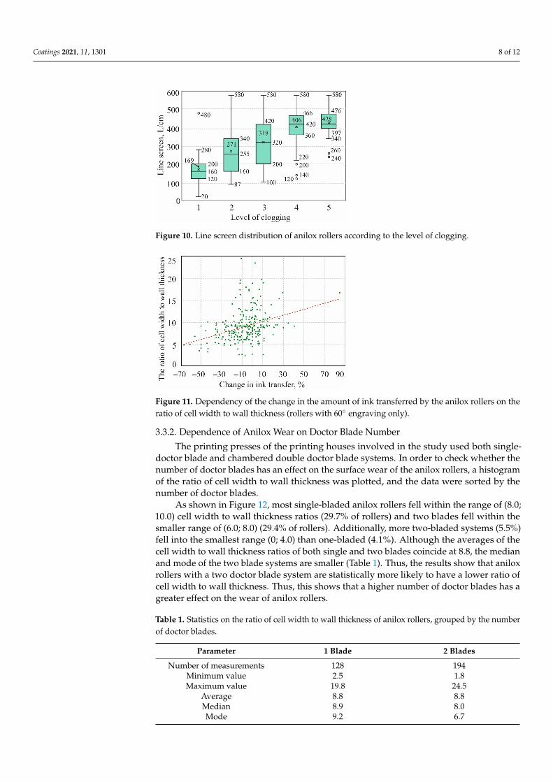
3.2. Dependence of Clogging on Cell Size
In practice, larger line screen anilox rollers are generally considered to be more difficultto clean. Figure 10 shows the line screen distribution of anilox rollers according to the levelof clogging. The graph shows that the higher the level of clogging, the higher the linescreen of the rollers—the averages increase from 169 L/cm at the first level of clogging to428 L/cm at the fifth level. It can also be observed that the higher the level of clogging, thehigher the minimum line screen of the anilox rollers entering it. This may mean that therollers of the lowest line screen are more difficult to clog—for example, 21 anilox rollerswith a line screen not exceeding 100 L/cm were measured, and none of the clogging levelswere higher than three. Meanwhile, the maximum line screen at each level of cloggingwas 580 L/cm, except at the first level, where it was 480 L/cm. Thus, it can be seen thateven very high line screen rollers can be maintained in conditions where there is a state ofunclogging or a state of nearly unclogging.
3.3. Wear of Anilox Rollers3.3.1. Wear Dependence on Cell Size
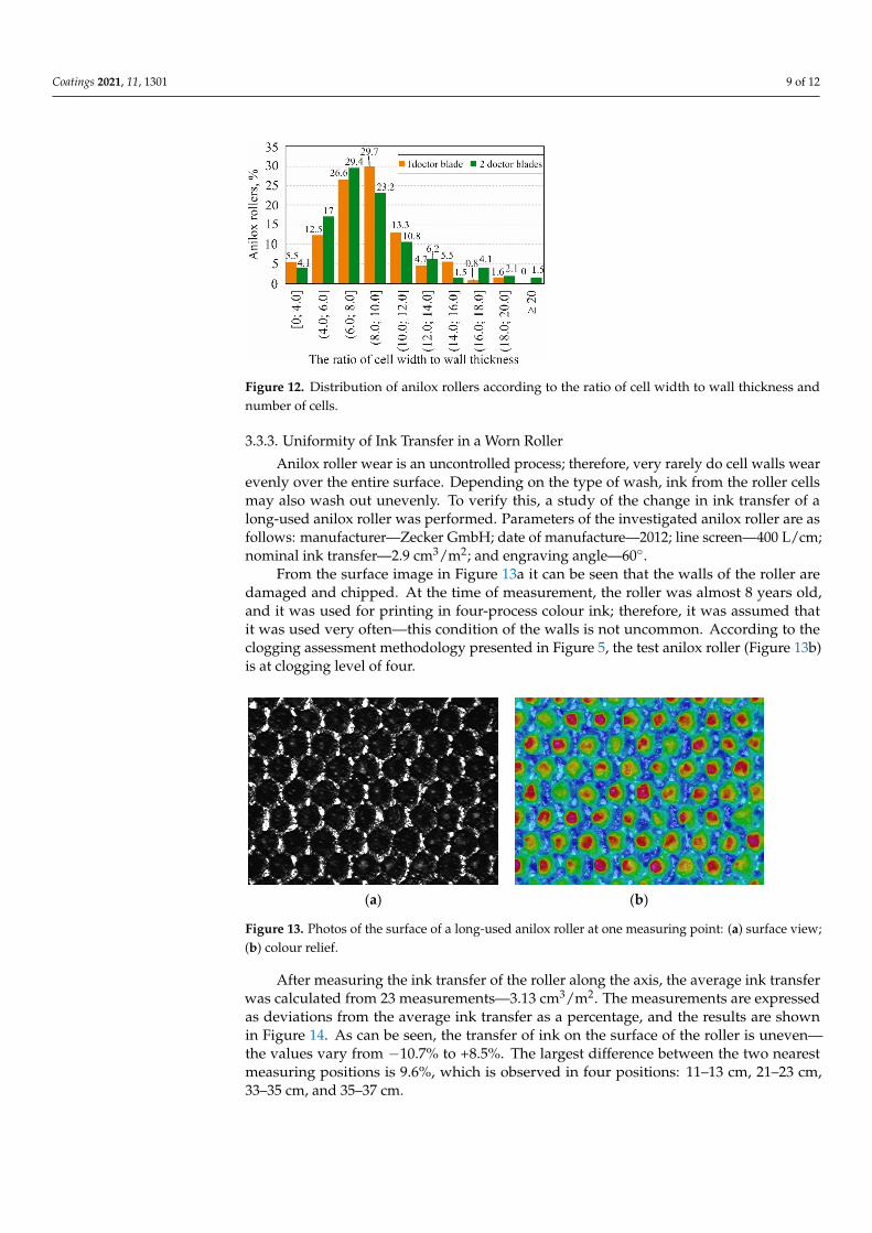
To compare the dependence of the change in ink transfer on the ratio of cell width towall thickness, a plotted diagram is shown in Figure 11. For more accurate data comparison,only rollers with a 60◦ engraving were used. The plotted mean data line shows that, as theratio of cell width to wall thickness decreases, the change in ink transfer from the declaredone also decreases.
Coatings 2021, 11, 1301 8 of 12Coatings 2021, 11, x FOR PEER REVIEW 8 of 12
Figure 10. Line screen distribution of anilox rollers according to the level of clogging.
3.3. Wear of Anilox Rollers 3.3.1. Wear Dependence on Cell Size
To compare the dependence of the change in ink transfer on the ratio of cell width to wall thickness, a plotted diagram is shown in Figure 11. For more accurate data compari-son, only rollers with a 60° engraving were used. The plotted mean data line shows that, as the ratio of cell width to wall thickness decreases, the change in ink transfer from the declared one also decreases.
Figure 11. Dependency of the change in the amount of ink transferred by the anilox rollers on the ratio of cell width to wall thickness (rollers with 60° engraving only).
3.3.2. Dependence of Anilox Wear on Doctor Blade Number The printing presses of the printing houses involved in the study used both single-
doctor blade and chambered double doctor blade systems. In order to check whether the number of doctor blades has an effect on the surface wear of the anilox rollers, a histogram of the ratio of cell width to wall thickness was plotted, and the data were sorted by the number of doctor blades.
As shown in Figure 12, most single-bladed anilox rollers fell within the range of (8.0; 10.0) cell width to wall thickness ratios (29.7% of rollers) and two blades fell within the smaller range of (6.0; 8.0) (29.4% of rollers). Additionally, more two-bladed systems (5.5%) fell into the smallest range (0; 4.0) than one-bladed (4.1%). Although the averages of the cell width to wall thickness ratios of both single and two blades coincide at 8.8, the median and mode of the two blade systems are smaller (Table 1). Thus, the results show that anilox rollers with a two doctor blade system are statistically more likely to have a lower ratio of cell width to wall thickness. Thus, this shows that a higher number of doctor blades has a greater effect on the wear of anilox rollers.
Figure 10. Line screen distribution of anilox rollers according to the level of clogging.
Coatings 2021, 11, x FOR PEER REVIEW 8 of 12
Figure 10. Line screen distribution of anilox rollers according to the level of clogging.
3.3. Wear of Anilox Rollers 3.3.1. Wear Dependence on Cell Size
To compare the dependence of the change in ink transfer on the ratio of cell width to wall thickness, a plotted diagram is shown in Figure 11. For more accurate data compari-son, only rollers with a 60° engraving were used. The plotted mean data line shows that, as the ratio of cell width to wall thickness decreases, the change in ink transfer from the declared one also decreases.
Figure 11. Dependency of the change in the amount of ink transferred by the anilox rollers on the ratio of cell width to wall thickness (rollers with 60° engraving only).
3.3.2. Dependence of Anilox Wear on Doctor Blade Number The printing presses of the printing houses involved in the study used both single-
doctor blade and chambered double doctor blade systems. In order to check whether the number of doctor blades has an effect on the surface wear of the anilox rollers, a histogram of the ratio of cell width to wall thickness was plotted, and the data were sorted by the number of doctor blades.
As shown in Figure 12, most single-bladed anilox rollers fell within the range of (8.0; 10.0) cell width to wall thickness ratios (29.7% of rollers) and two blades fell within the smaller range of (6.0; 8.0) (29.4% of rollers). Additionally, more two-bladed systems (5.5%) fell into the smallest range (0; 4.0) than one-bladed (4.1%). Although the averages of the cell width to wall thickness ratios of both single and two blades coincide at 8.8, the median and mode of the two blade systems are smaller (Table 1). Thus, the results show that anilox rollers with a two doctor blade system are statistically more likely to have a lower ratio of cell width to wall thickness. Thus, this shows that a higher number of doctor blades has a greater effect on the wear of anilox rollers.
Figure 11. Dependency of the change in the amount of ink transferred by the anilox rollers on theratio of cell width to wall thickness (rollers with 60◦ engraving only).
3.3.2. Dependence of Anilox Wear on Doctor Blade Number
The printing presses of the printing houses involved in the study used both single-doctor blade and chambered double doctor blade systems. In order to check whether thenumber of doctor blades has an effect on the surface wear of the anilox rollers, a histogramof the ratio of cell width to wall thickness was plotted, and the data were sorted by thenumber of doctor blades.
As shown in Figure 12, most single-bladed anilox rollers fell within the range of (8.0;10.0) cell width to wall thickness ratios (29.7% of rollers) and two blades fell within thesmaller range of (6.0; 8.0) (29.4% of rollers). Additionally, more two-bladed systems (5.5%)fell into the smallest range (0; 4.0) than one-bladed (4.1%). Although the averages of thecell width to wall thickness ratios of both single and two blades coincide at 8.8, the medianand mode of the two blade systems are smaller (Table 1). Thus, the results show that aniloxrollers with a two doctor blade system are statistically more likely to have a lower ratio ofcell width to wall thickness. Thus, this shows that a higher number of doctor blades has agreater effect on the wear of anilox rollers.
Table 1. Statistics on the ratio of cell width to wall thickness of anilox rollers, grouped by the numberof doctor blades.
Parameter 1 Blade 2 Blades
Number of measurements 128 194Minimum value 2.5 1.8Maximum value 19.8 24.5
Average 8.8 8.8Median 8.9 8.0Mode 9.2 6.7
Coatings 2021, 11, 1301 9 of 12Coatings 2021, 11, x FOR PEER REVIEW 9 of 12
Figure 12. Distribution of anilox rollers according to the ratio of cell width to wall thickness and number of cells.
Table 1. Statistics on the ratio of cell width to wall thickness of anilox rollers, grouped by the number of doctor blades.
Parameter 1 Blade 2 Blades Number of measurements 128 194
Minimum value 2.5 1.8 Maximum value 19.8 24.5
Average 8.8 8.8 Median 8.9 8.0 Mode 9.2 6.7
3.3.3. Uniformity of Ink Transfer in a Worn Roller Anilox roller wear is an uncontrolled process; therefore, very rarely do cell walls
wear evenly over the entire surface. Depending on the type of wash, ink from the roller cells may also wash out unevenly. To verify this, a study of the change in ink transfer of a long-used anilox roller was performed. Parameters of the investigated anilox roller are as follows: manufacturer—Zecker GmbH; date of manufacture—2012; line screen—400 L/cm; nominal ink transfer—2.9 cm3/m2; and engraving angle—60°.
From the surface image in Figure 13a it can be seen that the walls of the roller are damaged and chipped. At the time of measurement, the roller was almost 8 years old, and it was used for printing in four-process colour ink; therefore, it was assumed that it was used very often—this condition of the walls is not uncommon. According to the clogging assessment methodology presented in Figure 5, the test anilox roller (Figure 13b) is at clogging level of four.
(a) (b)
Figure 13. Photos of the surface of a long-used anilox roller at one measuring point: (a) surface view; (b) colour relief.
Figure 12. Distribution of anilox rollers according to the ratio of cell width to wall thickness andnumber of cells.
3.3.3. Uniformity of Ink Transfer in a Worn Roller
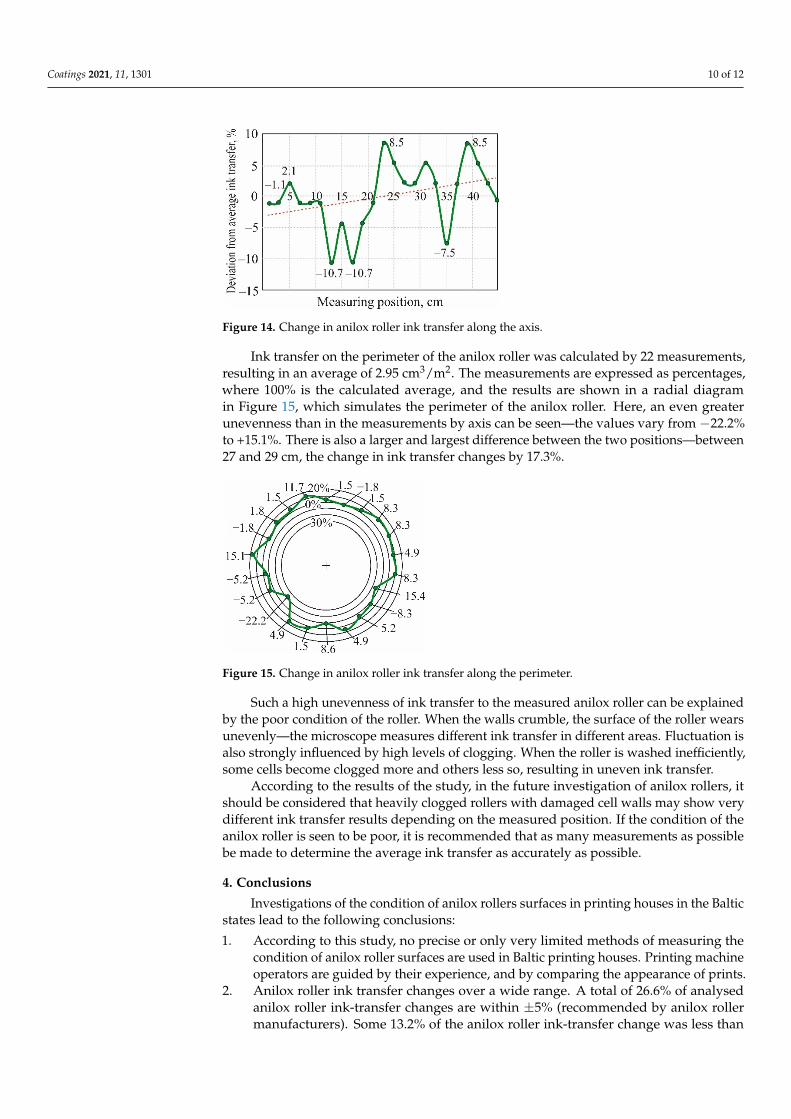
Anilox roller wear is an uncontrolled process; therefore, very rarely do cell walls wearevenly over the entire surface. Depending on the type of wash, ink from the roller cellsmay also wash out unevenly. To verify this, a study of the change in ink transfer of along-used anilox roller was performed. Parameters of the investigated anilox roller are asfollows: manufacturer—Zecker GmbH; date of manufacture—2012; line screen—400 L/cm;nominal ink transfer—2.9 cm3/m2; and engraving angle—60◦.
From the surface image in Figure 13a it can be seen that the walls of the roller aredamaged and chipped. At the time of measurement, the roller was almost 8 years old,and it was used for printing in four-process colour ink; therefore, it was assumed thatit was used very often—this condition of the walls is not uncommon. According to theclogging assessment methodology presented in Figure 5, the test anilox roller (Figure 13b)is at clogging level of four.
Coatings 2021, 11, x FOR PEER REVIEW 9 of 12
Figure 12. Distribution of anilox rollers according to the ratio of cell width to wall thickness and number of cells.
Table 1. Statistics on the ratio of cell width to wall thickness of anilox rollers, grouped by the number of doctor blades.
Parameter 1 Blade 2 Blades Number of measurements 128 194
Minimum value 2.5 1.8 Maximum value 19.8 24.5
Average 8.8 8.8 Median 8.9 8.0 Mode 9.2 6.7
3.3.3. Uniformity of Ink Transfer in a Worn Roller Anilox roller wear is an uncontrolled process; therefore, very rarely do cell walls
wear evenly over the entire surface. Depending on the type of wash, ink from the roller cells may also wash out unevenly. To verify this, a study of the change in ink transfer of a long-used anilox roller was performed. Parameters of the investigated anilox roller are as follows: manufacturer—Zecker GmbH; date of manufacture—2012; line screen—400 L/cm; nominal ink transfer—2.9 cm3/m2; and engraving angle—60°.
From the surface image in Figure 13a it can be seen that the walls of the roller are damaged and chipped. At the time of measurement, the roller was almost 8 years old, and it was used for printing in four-process colour ink; therefore, it was assumed that it was used very often—this condition of the walls is not uncommon. According to the clogging assessment methodology presented in Figure 5, the test anilox roller (Figure 13b) is at clogging level of four.
(a) (b)
Figure 13. Photos of the surface of a long-used anilox roller at one measuring point: (a) surface view; (b) colour relief. Figure 13. Photos of the surface of a long-used anilox roller at one measuring point: (a) surface view;(b) colour relief.
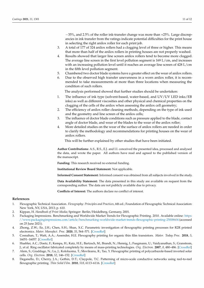
After measuring the ink transfer of the roller along the axis, the average ink transferwas calculated from 23 measurements—3.13 cm3/m2. The measurements are expressedas deviations from the average ink transfer as a percentage, and the results are shownin Figure 14. As can be seen, the transfer of ink on the surface of the roller is uneven—the values vary from −10.7% to +8.5%. The largest difference between the two nearestmeasuring positions is 9.6%, which is observed in four positions: 11–13 cm, 21–23 cm,33–35 cm, and 35–37 cm.
Coatings 2021, 11, 1301 10 of 12
Coatings 2021, 11, x FOR PEER REVIEW 10 of 12
After measuring the ink transfer of the roller along the axis, the average ink transfer was calculated from 23 measurements—3.13 cm3/m2. The measurements are expressed as deviations from the average ink transfer as a percentage, and the results are shown in Figure 14. As can be seen, the transfer of ink on the surface of the roller is uneven—the values vary from −10.7% to +8.5%. The largest difference between the two nearest meas-uring positions is 9.6%, which is observed in four positions: 11–13 cm, 21–23 cm, 33–35 cm, and 35–37 cm.
Figure 14. Change in anilox roller ink transfer along the axis.
Ink transfer on the perimeter of the anilox roller was calculated by 22 measurements, resulting in an average of 2.95 cm3/m2. The measurements are expressed as percentages, where 100% is the calculated average, and the results are shown in a radial diagram in Figure 15, which simulates the perimeter of the anilox roller. Here, an even greater une-venness than in the measurements by axis can be seen—the values vary from −22.2% to +15.1%. There is also a larger and largest difference between the two positions—between 27 and 29 cm, the change in ink transfer changes by 17.3%.
Figure 15. Change in anilox roller ink transfer along the perimeter.
Such a high unevenness of ink transfer to the measured anilox roller can be explained by the poor condition of the roller. When the walls crumble, the surface of the roller wears unevenly—the microscope measures different ink transfer in different areas. Fluctuation is also strongly influenced by high levels of clogging. When the roller is washed ineffi-ciently, some cells become clogged more and others less so, resulting in uneven ink trans-fer.
According to the results of the study, in the future investigation of anilox rollers, it should be considered that heavily clogged rollers with damaged cell walls may show very different ink transfer results depending on the measured position. If the condition of the anilox roller is seen to be poor, it is recommended that as many measurements as possible be made to determine the average ink transfer as accurately as possible.
Figure 14. Change in anilox roller ink transfer along the axis.
Ink transfer on the perimeter of the anilox roller was calculated by 22 measurements,resulting in an average of 2.95 cm3/m2. The measurements are expressed as percentages,where 100% is the calculated average, and the results are shown in a radial diagramin Figure 15, which simulates the perimeter of the anilox roller. Here, an even greaterunevenness than in the measurements by axis can be seen—the values vary from −22.2%to +15.1%. There is also a larger and largest difference between the two positions—between27 and 29 cm, the change in ink transfer changes by 17.3%.
Coatings 2021, 11, x FOR PEER REVIEW 10 of 12
After measuring the ink transfer of the roller along the axis, the average ink transfer was calculated from 23 measurements—3.13 cm3/m2. The measurements are expressed as deviations from the average ink transfer as a percentage, and the results are shown in Figure 14. As can be seen, the transfer of ink on the surface of the roller is uneven—the values vary from −10.7% to +8.5%. The largest difference between the two nearest meas-uring positions is 9.6%, which is observed in four positions: 11–13 cm, 21–23 cm, 33–35 cm, and 35–37 cm.
Figure 14. Change in anilox roller ink transfer along the axis.
Ink transfer on the perimeter of the anilox roller was calculated by 22 measurements, resulting in an average of 2.95 cm3/m2. The measurements are expressed as percentages, where 100% is the calculated average, and the results are shown in a radial diagram in Figure 15, which simulates the perimeter of the anilox roller. Here, an even greater une-venness than in the measurements by axis can be seen—the values vary from −22.2% to +15.1%. There is also a larger and largest difference between the two positions—between 27 and 29 cm, the change in ink transfer changes by 17.3%.
Figure 15. Change in anilox roller ink transfer along the perimeter.
Such a high unevenness of ink transfer to the measured anilox roller can be explained by the poor condition of the roller. When the walls crumble, the surface of the roller wears unevenly—the microscope measures different ink transfer in different areas. Fluctuation is also strongly influenced by high levels of clogging. When the roller is washed ineffi-ciently, some cells become clogged more and others less so, resulting in uneven ink trans-fer.
According to the results of the study, in the future investigation of anilox rollers, it should be considered that heavily clogged rollers with damaged cell walls may show very different ink transfer results depending on the measured position. If the condition of the anilox roller is seen to be poor, it is recommended that as many measurements as possible be made to determine the average ink transfer as accurately as possible.
Figure 15. Change in anilox roller ink transfer along the perimeter.
Such a high unevenness of ink transfer to the measured anilox roller can be explainedby the poor condition of the roller. When the walls crumble, the surface of the roller wearsunevenly—the microscope measures different ink transfer in different areas. Fluctuation isalso strongly influenced by high levels of clogging. When the roller is washed inefficiently,some cells become clogged more and others less so, resulting in uneven ink transfer.
According to the results of the study, in the future investigation of anilox rollers, itshould be considered that heavily clogged rollers with damaged cell walls may show verydifferent ink transfer results depending on the measured position. If the condition of theanilox roller is seen to be poor, it is recommended that as many measurements as possiblebe made to determine the average ink transfer as accurately as possible.
4. Conclusions
Investigations of the condition of anilox rollers surfaces in printing houses in the Balticstates lead to the following conclusions:
1. According to this study, no precise or only very limited methods of measuring thecondition of anilox roller surfaces are used in Baltic printing houses. Printing machineoperators are guided by their experience, and by comparing the appearance of prints.
2. Anilox roller ink transfer changes over a wide range. A total of 26.6% of analysedanilox roller ink-transfer changes are within ±5% (recommended by anilox rollermanufacturers). Some 13.2% of the anilox roller ink-transfer change was less than
Coatings 2021, 11, 1301 11 of 12
−35%, and 2.5% of the roller ink-transfer change was more than +25%. Large discrep-ancies in ink transfer from the ratings indicate potential difficulties for the print housein selecting the right anilox roller for each print job.
3. A total of 177 of 324 anilox rollers had a clogging level of three or higher. This meansthat more than half of the anilox rollers in printing houses are not properly washed.
4. Results showed that larger line screen anilox rollers tend to become more clogged.The average line screen in the first level pollution segment is 169 L/cm, and increaseswith an increasing pollution level until it reaches an average line screen of 428 L/cmin the fifth level pollution segment.
5. Chambered two doctor blade systems have a greater effect on the wear of anilox rollers.6. Due to the observed high transfer unevenness in a worn anilox roller, it is recom-
mended to take measurements at more than three locations when measuring thecondition of such rollers.
The analysis performed showed that further studies should be undertaken:
1. The influence of ink type (solvent-based, water-based, and UV/UV LED inks/EBinks) as well as different viscosities and other physical and chemical properties on theclogging of the cells of the anilox when assessing the anilox cell geometry;
2. The efficiency of anilox roller cleaning methods, depending on the type of ink usedand the geometry and line screen of the anilox cells;
3. The influence of doctor blade conditions such as pressure applied to the blade, contactangle of doctor blade, and wear of the blades to the wear of the anilox roller;
4. More detailed studies on the wear of the surface of anilox rollers are needed in orderto clarify the methodology and recommendations for printing houses on the wear ofanilox rollers.
This will be further explained by other studies that have been initiated.
Author Contributions: A.S., R.S., E.J. and I.I. conceived the presented idea, processed and analysedthe data, and wrote the paper. All authors have read and agreed to the published version ofthe manuscript.
Funding: This research received no external funding.
Institutional Review Board Statement: Not applicable.
Informed Consent Statement: Informed consent was obtained from all subjects involved in the study.
Data Availability Statement: The data presented in this study are available on request from thecorresponding author. The data are not publicly available due to privacy.
Conflicts of Interest: The authors declare no conflict of interest.
References1. Flexographic Technical Association. Flexography: Principles and Practices, 6th ed.; Foundation of Flexographic Technical Association:
New York, NY, USA, 2013; p. 610.2. Kippan, H. Handbook of Print Media; Springer: Berlin/Heidelberg, Germany, 2001.3. Packaging Impressions. Benchmarking and Worldwide Market Trends for Flexographic Printing. 2010. Available online: https:
//www.packagingimpressions.com/article/benchmarking-worldwide-market-trends-flexographic-printing-25008604 (accessedon 25 June 2021).
4. Zhong, Z.W.; Ee, J.H.; Chen, S.H.; Shan, X.C. Parametric investigation of flexographic printing processes for R2R printedelectronics. Mater. Manufact. Proc. 2020, 35, 564–571. [CrossRef]
5. Cosnahan, T.; Watt, A.A.; Assender, H.E. Flexography printing for organic thin film transistors. Mater. Today Proc. 2018, 5,16051–16057. [CrossRef]
6. Huebler, A.C.; Doetz, F.; Kempa, H.; Katz, H.E.; Bartzsch, M.; Brandt, N.; Hennig, I.; Fuegmann, U.; Vaidyanathan, S.; Granstrom,J.; et al. Ring oscillator fabricated completely by means of mass-printing technologies. Org. Electron. 2007, 8, 480–486. [CrossRef]
7. Alem, S.; Graddage, N.; Lu, J.; Kololuoma, T.; Movileanu, R.; Tao, Y. Flexographic printing of polycarbazole-based inverted solarcells. Org. Electron. 2018, 52, 146–152. [CrossRef]
8. Deganello, D.; Cherry, J.A.; Gethin, D.T.; Claypole, T.C. Patterning of micro-scale conductive networks using reel-to-reelflexographic printing. Thin Solid Film. 2010, 518, 6113–6116. [CrossRef]
Coatings 2021, 11, 1301 12 of 12
9. Deganello, D.; Cherry, J.A.; Gethin, D.T.; Claypole, T.C. Impact of metered ink volume on reel-to-reel flexographic printedconductive networks for enhanced thin film conductivity. Thin Solid Film. 2012, 520, 2233–2237. [CrossRef]
10. Johnson, J. Aspects of Flexographic Print Quality and Relationship to some Printing Parameters. Ph.D. Thesis, Karlstad University,Karlstad, Sweden, 2008.
11. Johnson, J. The Influence of Moisture, Temperature, Pressure Pulse and Substrate on Print Quality in Flexographic Printing. Ph.D.Thesis, Karlstad University, Karlstad, Sweden, 2003.
12. Valdec, D.; Zjakic, I.; Milkovic, M. The influence of variable parameters of flexographic printing on dot geometry of pre-printedprinting substrate. Tech. Gaz. 2013, 20, 659–667.
13. Folea, G.V.; Cazac, V. The Analysis of particularities and possibilities for ensuring quality in flexo printing. Ann. Acad. Rom. Sci.Ser. Eng. Sci. 2017, 9, 35–48.
14. Havenko, S.; Ohirko, M.; Ryvak, P.; Kotmalova, O. Determining the factors that affect the quality of test prints at flexographicprinting. East.-Eur. J. Enterp. Technol. 2020, 2, 104. [CrossRef]
15. Gencoglu, E.F. E Influence of ink viscosity on dot gain and print density in flexography. Asian J. Chem. 2012, 5, 1999–2002.16. Gu, C.; Wang, Y.; Xing, J.; Dai, H. On the influence of viscosity of water-based inks and how the viscosity influences the dot gain
in flexographic printing. J. Beijing Inst. Graph. Commun. 2008, 4, 4.17. Borbély, Á.; Szentgyörgyvölgyi, R. Colorimetric properties of flexographic printed foils: The effect of impression. Óbuda Univ.
e-Bull. 2011, 2, 31–36.18. Lipiak, J. Methodology for assessing the factors affecting the quality and efficiency of flexographic printing process. Procedia Eng.
2017, 182, 403–411. [CrossRef]19. Bould, D.; Claypole, T.C.; Galton, D. Process parameters in flexography: Effect on UV ink transfer and image quality characteristics.
J. Print Media Technol. Res. 2012, 1, 41–49.20. Morgan, M.L.; Holder, A.; Curtis, D.J.; Deganello, D. Formulation, characterisation and flexographic printing of novel Boger
fluids to assess the effects of ink elasticity on print uniformity. Rheol. Acta 2018, 57, 105–112. [CrossRef]21. James, A. Anilox Technology Applications; FlexoTech: London, UK, 2013; pp. 36–37.22. Cherry, J.A. Ink Release Characteristics of Anilox Rolls. Ph.D. Thesis, Swansea University, Swansea, UK, 2007.23. Harper. Specifying the Right Anilox Roll; Harper Anilox & Coating Division: Charlotte, NC, USA, 2020. Available online:
http://www.harperimage.com/AniloxRolls/Anilox-Guides/Specifying-the-Right-Anilox (accessed on 25 June 2020).24. Bould, D.C.; Hamblyn, S.M.; Gethin, D.T.; Claypole, T.C. Effect of impression pressure and anilox specification on solid and
halftone density. Proc. Inst. Mech. Eng. Part B J. Eng. Manuf. 2011, 225, 699–709. [CrossRef]25. Blagodir, O.; Velychko, O. Study of anilox cell geometry impact on the ink volume transferred to the printing plate. Przeglad Pap.
2016, 72, 443–447.26. Poppen, M. The Secret to Print Consistency: Maintaining Anilox Roll Volume; FTA: New York, NY, USA, 2020. Available online:
https://www.flexography.org/industry-news/print-consistency-maintain-anilox-roll-volume (accessed on 20 June 2020).27. Provident Group Ltd. Troika Group Ltd. Do You Really Know the Volume of Your Anilox Rolls? Provident LLC: Appleton, WI, USA,
2008. Available online: https://www.providentgrp.com/do-you-really-know-the-volume-of-your-anilox-rolls (accessed on20 June 2020).
28. Reilly, D.; Claypole, T.; Cox, K. Measuring Anilox Volume: FQC’s Gauge R&R Study; FTA: New York, NY, USA, 2010. Availableonline: https://www.flexography.org/industry-news/measuring-anilox-volume-fqc-gauge-rr-study (accessed on 20 June 2020).
29. Khmiliarchuk, O.I.; Shubko, Y.S. Modeling of Anilox Cells Pollution Process; ELAKPI: Kiev, Ukraine, 2016. Available online:https://ela.kpi.ua/handle/123456789/16538 (accessed on 10 February 2021).
30. Savickas, A.; Stonkus, R.; Jurkonis, E. Investigation of anilox roller cell clogging. J. Graph. Eng. Des. 2020, 11, 61–67. [CrossRef]