The Effect of Temper Condition and Feeding Speed on ... - MDPI
16
materials Article The Effect of Temper Condition and Feeding Speed on the Additive Manufacturing of AA2011 Parts Using Friction Stir Deposition Mohamed M. Z. Ahmed 1,2, * , Mohamed M. El-Sayed Seleman 2 , Ebtessam Elfishawy 2,3 , Bandar Alzahrani 1 , Kamel Touileb 1 and Mohamed I. A. Habba 4 Citation: Ahmed, M.M.Z.; El-Sayed Seleman, M.M.; Elfishawy, E.; Alzahrani, B.; Touileb, K.; Habba, M.I.A. The Effect of Temper Condition and Feeding Speed on the Additive Manufacturing of AA2011 Parts Using Friction Stir Deposition. Materials 2021, 14, 6396. https:// doi.org/10.3390/ma14216396 Academic Editor: Józef Iwaszko Received: 9 September 2021 Accepted: 19 October 2021 Published: 25 October 2021 Publisher’s Note: MDPI stays neutral with regard to jurisdictional claims in published maps and institutional affil- iations. Copyright: © 2021 by the authors. Licensee MDPI, Basel, Switzerland. This article is an open access article distributed under the terms and conditions of the Creative Commons Attribution (CC BY) license (https:// creativecommons.org/licenses/by/ 4.0/). 1 Mechanical Engineering Department, College of Engineering at Al-Kharj, Prince Sattam Bin Abdulaziz University, Al Kharj 16273, Saudi Arabia; [email protected] (B.A.); [email protected] (K.T.) 2 Department of Metallurgical and Materials Engineering, Faculty of Petroleum and Mining Engineering, Suez University, Suez 43512, Egypt; [email protected] (M.M.E.-S.S.); ebtessam.elfi[email protected] (E.E.) 3 Mechanical Engineering Department, School of Science and Engineering, The American University in Cairo, 11835 New Cairo, Egypt 4 Mechanical Department, Faculty of Technology & Education, Suez University, Suez 43518, Egypt; [email protected] * Correspondence: [email protected] Abstract: In the current study, solid-state additive manufacturing (SSAM) of two temper conditions AA2011 was successfully conducted using the friction stir deposition (FSD) process. The AA2011- T6 and AA2011-O consumable bars of 20 mm diameter were used as a feeding material against AA5083 substrate. The effect of the rotation rate and feeding speed of the consumable bars on the macrostructure, microstructure, and hardness of the friction stir deposited (FSD) materials were examined. The AA2011-T6 bars were deposited at a constant rotation rate of 1200 rpm and different feeding speeds of 3, 6, and 9 mm/min, whereas the AA2011-O bars were deposited at a constant rotation rate of 200 mm/min and varied feeding speeds of 1, 2, and 3 mm/min. The obtained microstructure was investigated using an optical microscope and scanning electron microscope equipped with EDS analysis to evaluate microstructural features. Hardness was also assessed as average values and maps. The results showed that this new technique succeeded in producing sound additive manufactured parts at all the applied processing parameters. The microstructures of the additive manufactured parts showed equiaxed refined grains compared to the coarse grain of the starting materials. The detected intermetallics in AA2011 alloy are mainly Al 2 Cu and Al 7 Cu 2 Fe. The improvement in hardness of AA2011-O AMPs reached 163% of the starting material hardness at the applied feeding speed of 1 mm/min. The hardness mapping analysis reveals a homogeneous hardness profile along the building direction. Finally, it can be said that the temper conditions of the starting AA2011 materials govern the selection of the processing parameters in terms of rotation rate and feeding speed and affects the properties of the produced additive manufactured parts in terms of hardness and microstructural features. Keywords: friction stir deposition; solid-state additive manufacturing; AA2011-T6 and AA2011-O; AA2011 aluminum alloy; microstructure; intermetallics; hardness 1. Introduction Additive manufacturing (AM) is a promising technology in numerous engineering ap- plications. It involves the fabrication of various 3D objects by adding layer by layer material (alloy, plastic, concrete, human tissue, etc.) regardless of any size and shape [1,2]. Fusion- based additive manufacturing (F-BAM) techniques are used for different alloys [3]. Still, they are not suitable for aluminum-based alloys, especially the heat-treatable alloys (2xxx Materials 2021, 14, 6396. https://doi.org/10.3390/ma14216396 https://www.mdpi.com/journal/materials
-
Upload
khangminh22 -
Category
Documents
-
view
0 -
download
0
Transcript of The Effect of Temper Condition and Feeding Speed on ... - MDPI
materials
Article
The Effect of Temper Condition and Feeding Speed on theAdditive Manufacturing of AA2011 Parts Using FrictionStir Deposition
Mohamed M. Z. Ahmed 1,2,* , Mohamed M. El-Sayed Seleman 2 , Ebtessam Elfishawy 2,3, Bandar Alzahrani 1,Kamel Touileb 1 and Mohamed I. A. Habba 4
�����������������
Citation: Ahmed, M.M.Z.; El-Sayed
Seleman, M.M.; Elfishawy, E.;
Alzahrani, B.; Touileb, K.; Habba,
M.I.A. The Effect of Temper
Condition and Feeding Speed on the
Additive Manufacturing of AA2011
Parts Using Friction Stir Deposition.
Materials 2021, 14, 6396. https://
doi.org/10.3390/ma14216396
Academic Editor: Józef Iwaszko
Received: 9 September 2021
Accepted: 19 October 2021
Published: 25 October 2021
Publisher’s Note: MDPI stays neutral
with regard to jurisdictional claims in
published maps and institutional affil-
iations.
Copyright: © 2021 by the authors.
Licensee MDPI, Basel, Switzerland.
This article is an open access article
distributed under the terms and
conditions of the Creative Commons
Attribution (CC BY) license (https://
creativecommons.org/licenses/by/
4.0/).
1 Mechanical Engineering Department, College of Engineering at Al-Kharj,Prince Sattam Bin Abdulaziz University, Al Kharj 16273, Saudi Arabia; [email protected] (B.A.);[email protected] (K.T.)
2 Department of Metallurgical and Materials Engineering, Faculty of Petroleum and Mining Engineering,Suez University, Suez 43512, Egypt; [email protected] (M.M.E.-S.S.);[email protected] (E.E.)
3 Mechanical Engineering Department, School of Science and Engineering, The American University in Cairo,11835 New Cairo, Egypt
4 Mechanical Department, Faculty of Technology & Education, Suez University, Suez 43518, Egypt;[email protected]
* Correspondence: [email protected]
Abstract: In the current study, solid-state additive manufacturing (SSAM) of two temper conditionsAA2011 was successfully conducted using the friction stir deposition (FSD) process. The AA2011-T6 and AA2011-O consumable bars of 20 mm diameter were used as a feeding material againstAA5083 substrate. The effect of the rotation rate and feeding speed of the consumable bars on themacrostructure, microstructure, and hardness of the friction stir deposited (FSD) materials wereexamined. The AA2011-T6 bars were deposited at a constant rotation rate of 1200 rpm and differentfeeding speeds of 3, 6, and 9 mm/min, whereas the AA2011-O bars were deposited at a constantrotation rate of 200 mm/min and varied feeding speeds of 1, 2, and 3 mm/min. The obtainedmicrostructure was investigated using an optical microscope and scanning electron microscopeequipped with EDS analysis to evaluate microstructural features. Hardness was also assessed asaverage values and maps. The results showed that this new technique succeeded in producing soundadditive manufactured parts at all the applied processing parameters. The microstructures of theadditive manufactured parts showed equiaxed refined grains compared to the coarse grain of thestarting materials. The detected intermetallics in AA2011 alloy are mainly Al2Cu and Al7Cu2Fe. Theimprovement in hardness of AA2011-O AMPs reached 163% of the starting material hardness atthe applied feeding speed of 1 mm/min. The hardness mapping analysis reveals a homogeneoushardness profile along the building direction. Finally, it can be said that the temper conditions of thestarting AA2011 materials govern the selection of the processing parameters in terms of rotation rateand feeding speed and affects the properties of the produced additive manufactured parts in termsof hardness and microstructural features.
Keywords: friction stir deposition; solid-state additive manufacturing; AA2011-T6 and AA2011-O;AA2011 aluminum alloy; microstructure; intermetallics; hardness
1. Introduction
Additive manufacturing (AM) is a promising technology in numerous engineering ap-plications. It involves the fabrication of various 3D objects by adding layer by layer material(alloy, plastic, concrete, human tissue, etc.) regardless of any size and shape [1,2]. Fusion-based additive manufacturing (F-BAM) techniques are used for different alloys [3]. Still,they are not suitable for aluminum-based alloys, especially the heat-treatable alloys (2xxx
Materials 2021, 14, 6396. https://doi.org/10.3390/ma14216396 https://www.mdpi.com/journal/materials

Materials 2021, 14, 6396 2 of 16
and 7xxx), due to their sensitivity to porosity formation, liquation cracking, segregation,solidification cracking, and anisotropic microstructure [2,4]. In contrast, friction stir depo-sition (FSD) is solid-state additive manufacturing (S-SAM) technique that can be used todeposit metals and composites [5,6]. The main advantage of the FSD as a solid-state processis that it can eliminate all problems of melting and solidification, and also, the feed materialis mainly rods or wire without a need for special specifications of the used feed material.Most of the current works today are carried out on AM of aluminum-based alloys using aS-SAM technique [1,7,8]. In recent years, there has been increasing interest in utilizing FSDin many applications. This technique can be used for many purposes, including additivemanufacturing [1,9–11], surface protection [11–13], and repair of defective components [6].Thus, it can be said that the FSD-based AM is considered a new innovative approach toAM for building 3D parts ultimately in a solid state. The main processing parameters arethe rotation rate, feeding speed, downward force, consumable rod material, and substratematerial. These parameters govern the heat input and material flow processes. In the FSDprocess, the final build part’s height depends on the layer thickness and the total numberof assembly layers. Moreover, the modifications in the geometry of the building design canobtain manufacturing parts with different geometries [1,5]. Thus, the final FSD product is anear-net-shape with enhanced microstructure and isotropic mechanical properties [2,4,14].Low porosity and low residual stress are the main privileges of the as-deposited part; thiswill make post-processing heat treatment unnecessary in many cases. However, surfacefinishing will usually be required [15–17]. Boeing and Airbus companies are considered thefirst use of additive manufacturing (AM) based on FSW principles [10,18,19]. Meanwhile,Airbus [20] presented the capability of achieving lightweight/low-cost structure parts bymanufacturing 2050 Al-Li wing ribs by the FSAM process. Boeing assessed this process asa pre-form fabricating tool for manufacturing energy-efficient structures [10,21,22]. In addi-tion to the capability of the FSD technique to generate material builds of high-performancestructures, it is considered an energy and cost-saving process [10,23]. Elfishawy et al. [24]studied the possibility of multi-layers formation of die-cast Al–Si via FSD at the spindlerotation rate of 1200 rpm and different feeding speeds from 3 to 5 mm/min. The resultsshowed sound structure with recrystallized refined grains. Therefore, from a scientificand technological point of view, it is of great importance to study how FSD works foradditive manufacturing parts (AMPs) production in heat-treatable aluminum alloys. Al-though AA2011 is used extensively in aerospace and automotive components, there is alack of publications discussing the applicability of AA2011 fabrication using FSD. Thus, thecurrent work intends to explore the effect of the initial material conditions of AA2011 alloyson the properties and microstructures of the final produced AMPs. Three levels of feedingspeeds of 3, 6, and 9 mm/min were associated with a high rotation rate of 1200 rpm/minto friction stir deposit AA2011-T6, and three other feeding speeds of 1, 2, and 3 mm/minwere chosen with a low rotation rate of 200 rpm/min to deposit AA2011-O.
This study aims to study the effect of the consumable rod alloy temper conditionon the behavior of the FSD process in terms of the parameters suitable for each tempercondition as well as the properties of the AMPs.
2. Materials and Methods
To study the effect of the temper condition of AA2011 alloy on the properties of theproduced AMPs, two groups of specimens, AA2011-T6 and AA2011-O, were used as con-sumable bars against a substrate of AA5083 alloy. The nominal chemical composition ofAA2011 is given in Table 1. The annealing process for the as-received was carried out at 415 ◦Cfor 2.5 h followed by slow furnace cooling to the room temperature. Figure 1 illustrates theCu-rich portion of the Al–Cu binary phase diagram with the annealing temperature rangeindicated [25,26].

Materials 2021, 14, 6396 3 of 16
Table 1. Chemical composition of AA2011 aluminum alloy (in wt.%).
Cu Fe Si Ti Zn Bi Pb Ni Mn Bal.
5.60 0.72 0.40 0.35 0.30 0.25 0.20 0.02 0.05 Al
Figure 1. A sketch for the Cu-rich portion of the Al–Cu binary phase diagram with the annealingtemperature range indicated.
For comparison, three deposited materials were manufactured from each group ofthe AA2011-T6 and AA2011-O rods. The FSAM was carried out using the friction stirwelding/processing machine (EG-FSW-M1) (Suez University, Suez, Egypt) [27,28]. Table 2summarizes the deposition process parameters of both Al alloys.
Table 2. Consumable rod dimensions and FSD processing parameters.
Consumable Rod FSD Parameters
MaterialInitialLength(mm)
RodDiameter
(mm)
RotationRate
(rpm)
Feeding Speeds(mm/min)
AA2011-T6 200 20 1200 3 6 9AA2011-O 110 20 200 1 2 3
The consumable aluminum rods are fixed using the machine shank to ensure thecomplete fixation of the rods throughout the process; Figure 2 shows a photograph ofthe actual AM process applied to AA2011. The additive manufacturing (AM) processinvolves three steps: fixing the consumable Al rod in the spindle shank (Figure 2a) androtating it at a constant rotation rate while moving downward to reach the substrate material(Figure 2b). Finally, under a continuous feeding speed, the rod plastically deformed due tothe high friction and the generated heat between the rod and the substrate that causes thematerial to transfer from the consumable bar to the substrate to build a material upwards.This process may continue until all the rod length is consumed and became insufficientfor more deposition. The shape of the consumed tool tends to form a conical shape, as

Materials 2021, 14, 6396 4 of 16
shown in Figure 2c. For AA2011-T6 group specimens, careful processing parameters wereselected based on our experience in the field and the published data [24,29] to produceadditive manufacturing parts. The required heat input to friction stir deposit such a hardmaterial limits the process parameters to be 1200 rpm as a spindle rotation rate with 3, 6,and 9 mm/min feeding speeds. For the AA2011-O group specimens, experiments startwith shortening each of the three specimens to 110 mm in length. Of this length, 70 mmof the total length was consumed as a fixing base of the rod inside the shank to ensuretight gripping and prevent rod deflection during the deposition process, and 40 mm wasfunctional during the process of friction deposition. Less heat input is needed to depositthis soft material; that is why after many trials, the optimum process parameters obtainedwere a 200 rpm spindle rotation rate and feeding speeds of 1, 2, and 3 mm/min. Figure 2d,eshow schematic drawings of the AMP sections showing hardness measurement points, andthe second half of AMP shows the specimens cut for OM and SEM examinations, respectively.
Figure 2. Photographs for the stages of the FSD process: (a) Fixing the AA2011 consumable rod andsubstrate AA5083 on the FSW/FSP machine, (b) feeding process during the FSD showing the buildingup of the part, and (c) the end of the deposition process for the additive manufacturing part (AMP).(d) and (e) are schematic drawings of the AMP sections showing hardness measurement points, andthe second half of AMP shows the specimens cut for OM and SEM examinations, respectively.
Additive manufacturing parts (AMPs) have been sectioned vertically along the build-ing direction (z-direction). The deposited layers were oriented perpendicular to the spec-imen axis/loading direction. The longitudinal sections were prepared according to thestandard metallographic procedures by grinding up to 0.05 µm alumina polishing surfacefinish. The polished sections were investigated using an optical microscope (Olympus,BX41M-LED, Tokyo, Japan) after etching according to ATSM standard E407 using Keller’setchant of the chemical composition of 100 mL distilled water and 3 mL hydrofluoric acid.Microstructural examinations of the AMPs were also carried out using a scanning electronmicroscope (SEM, FEI, Hillisboro, OR, USA). SEM examination was carried out on thelong-transverse sections of the cylindrical friction deposits using secondary electron (SE)imaging modes. Moreover, the grain size of all AM specimens and the base metal have

Materials 2021, 14, 6396 5 of 16
been analyzed by the grain interception method using Olympus Stream Motion Software.A Vickers Hardness Tester (Qness Q10, GmbH, Golling, Austria) with 0.2 kg load and15 s dwell time was used to evaluate the average hardness of the starting and the AMPs.This test was carried out according to ASTM E92 by measuring twelve readings at leastfor each AM specimen on the longitudinal sections of the cylindrical friction deposits. Thehardness maps were also drawn by collecting four horizontal (perpendicular to buildingdirection) lines and five vertical lines measurements across the AMPs. The free spacebetween any two indentations was 2 mm.
3. Results and Discussions3.1. Fabrication of AMPs
For conducting the friction stir deposition and forming the AMPs, the axis of theconsumable rod is positioned exactly in the center of the square-shaped substrate to ensurethe symmetry and homogeneity of heat dissipation through the substrate. Preliminarytests have been carried out to view the behavior of the rod to avoid buckling, physicaldiscontinuities, or other defects of the rod and ensure the build of the part. Based on thesepreliminary tests, the rotation speeds, feed rate, and length of the consumable rod havebeen chosen. In addition, the length of the consumable rod out of the shank holder isvaried with the temper condition, as the soft alloy tends to buckle easier than the hard alloythat allows more length to be used.
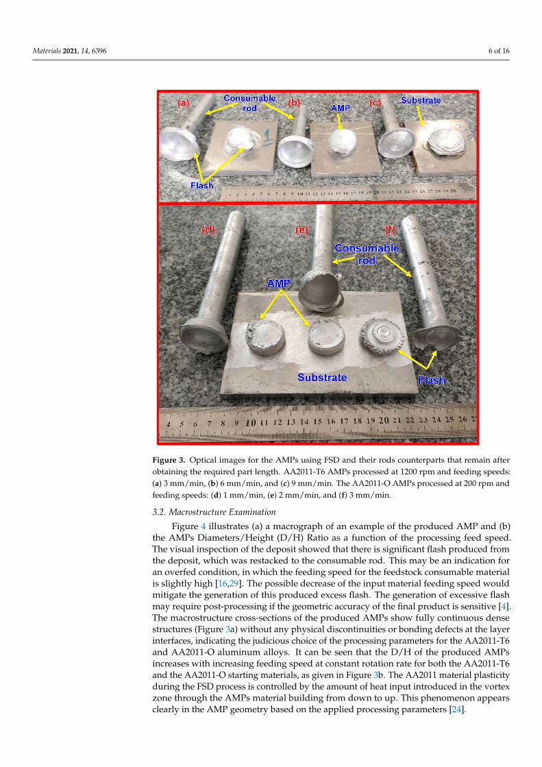
The rubbing between the two surfaces during the rotation and feeding speed of theconsumable rod generates frictional heat, which softens the rod’s rubbing end, causingplasticized material at the abutting ends. As the process continues, more plasticizedmaterial is built up [14,15]. As the required plasticized material thickness is gained, therotating consumable rod is stopped and withdrawn; this process promotes a depositedlayer on the substrate due to torsional shear. Figure 3 illustrates the remains of AA2011-T6and AA2011-O consumable rods and their AMPs. Figure 3a–c shows the produced AA2011-T6 AMPs fabricated at a constant rotation rate of 1200 rpm at different feeding speeds of3, 6, and 9 mm/min, respectively. For the AA2011-O specimens, the consumable rods ofAA2011-O are softer than the AA2011-T6 rods. Therefore, the energy required to softenthe AA2011-O consumable rod is lower than that needed for softening the AA2011-T6one [30]. Thus, the AM process was conducted after many trials at a constant rotationrate of 200 rpm and various feeding speeds of 1, 2, and 3 mm/min, as shown in Figure3d–f, respectively. It should be remarked that the higher feeding speeds of 9 mm/min and3 mm/min at the rotational rates of 1200 and 200 rpm, respectively, are not recommendedto fabricated AMPs of AA2011 alloys, where it is not easy to build continuous multi-layersupward to specific height and diameter. The increase in heat input due to an increase infeeding speed over the optimum condition also produces excessive flash around the AMPs,as given in Figure 3c for AA2011-T6 AMP and Figure 3f for AA2011-O AMP. Thus, it wasnoted that the conical shape at the end of the consumable rods after finishing the FSDprocess is flattened in a thin thickness, where the other materials are transferred to flasharound the fabricated AMPs.
Materials 2021, 14, 6396 6 of 16
Figure 3. Optical images for the AMPs using FSD and their rods counterparts that remain afterobtaining the required part length. AA2011-T6 AMPs processed at 1200 rpm and feeding speeds:(a) 3 mm/min, (b) 6 mm/min, and (c) 9 mm/min. The AA2011-O AMPs processed at 200 rpm andfeeding speeds: (d) 1 mm/min, (e) 2 mm/min, and (f) 3 mm/min.
3.2. Macrostructure Examination
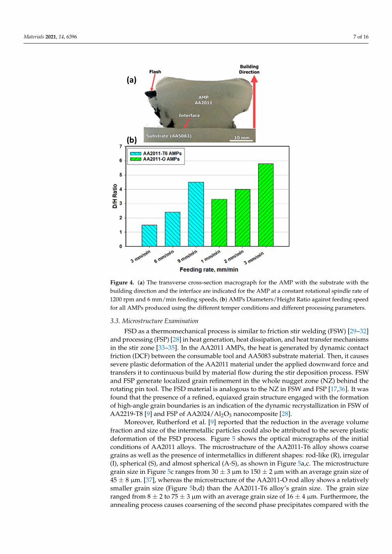
Figure 4 illustrates (a) a macrograph of an example of the produced AMP and (b)the AMPs Diameters/Height (D/H) Ratio as a function of the processing feed speed.The visual inspection of the deposit showed that there is significant flash produced fromthe deposit, which was restacked to the consumable rod. This may be an indication foran overfed condition, in which the feeding speed for the feedstock consumable materialis slightly high [16,29]. The possible decrease of the input material feeding speed wouldmitigate the generation of this produced excess flash. The generation of excessive flashmay require post-processing if the geometric accuracy of the final product is sensitive [4].The macrostructure cross-sections of the produced AMPs show fully continuous densestructures (Figure 3a) without any physical discontinuities or bonding defects at the layerinterfaces, indicating the judicious choice of the processing parameters for the AA2011-T6and AA2011-O aluminum alloys. It can be seen that the D/H of the produced AMPsincreases with increasing feeding speed at constant rotation rate for both the AA2011-T6and the AA2011-O starting materials, as given in Figure 3b. The AA2011 material plasticityduring the FSD process is controlled by the amount of heat input introduced in the vortexzone through the AMPs material building from down to up. This phenomenon appearsclearly in the AMP geometry based on the applied processing parameters [24].
Materials 2021, 14, 6396 7 of 16
Figure 4. (a) The transverse cross-section macrograph for the AMP with the substrate with thebuilding direction and the interface are indicated for the AMP at a constant rotational spindle rate of1200 rpm and 6 mm/min feeding speeds, (b) AMPs Diameters/Height Ratio against feeding speedfor all AMPs produced using the different temper conditions and different processing parameters.
3.3. Microstructure Examination
FSD as a thermomechanical process is similar to friction stir welding (FSW) [29–32]and processing (FSP) [28] in heat generation, heat dissipation, and heat transfer mechanismsin the stir zone [33–35]. In the AA2011 AMPs, the heat is generated by dynamic contactfriction (DCF) between the consumable tool and AA5083 substrate material. Then, it causessevere plastic deformation of the AA2011 material under the applied downward force andtransfers it to continuous build by material flow during the stir deposition process. FSWand FSP generate localized grain refinement in the whole nugget zone (NZ) behind therotating pin tool. The FSD material is analogous to the NZ in FSW and FSP [17,36]. It wasfound that the presence of a refined, equiaxed grain structure engaged with the formationof high-angle grain boundaries is an indication of the dynamic recrystallization in FSW ofAA2219-T8 [9] and FSP of AA2024/Al2O3 nanocomposite [28].
Moreover, Rutherford et al. [9] reported that the reduction in the average volumefraction and size of the intermetallic particles could also be attributed to the severe plasticdeformation of the FSD process. Figure 5 shows the optical micrographs of the initialconditions of AA2011 alloys. The microstructure of the AA2011-T6 alloy shows coarsegrains as well as the presence of intermetallics in different shapes: rod-like (R), irregular(I), spherical (S), and almost spherical (A-S), as shown in Figure 5a,c. The microstructuregrain size in Figure 5c ranges from 30 ± 3 µm to 150 ± 2 µm with an average grain size of45 ± 8 µm. [37], whereas the microstructure of the AA2011-O rod alloy shows a relativelysmaller grain size (Figure 5b,d) than the AA2011-T6 alloy’s grain size. The grain sizeranged from 8 ± 2 to 75 ± 3 µm with an average grain size of 16 ± 4 µm. Furthermore, theannealing process causes coarsening of the second phase precipitates compared with the

Materials 2021, 14, 6396 8 of 16
AA2011-T6 material, transferring their shape from the rod-like shape (Figure 5c) to morespheroidal-shaped precipitates (Figure 5d).
Figure 5. Low and high-magnification optical micrographs of the different temper conditions basematerial: (a,c) AA2011-T6 and (b,d) AA2011-O.
3.3.1. AMPs Parts Produced from AA2011-T6 Alloy
The friction-based processes contribute to the increase of temperature of the materialin the stirring zone to the temperature range between 60% and 90% of the melting point ofthe processed material, which is high enough for the recrystallization during the intensiveplastic deformation through the solid-state deposition process [38,39]. Figure 6 representsthe microstructures of the AA2011-T6 (Figure 6a) and the AMPs deposited at 1200 rpmspindle rotation rate and different feeding speeds of 3 mm/min (Figure 6b), 6 mm/min(Figure 6c), and 9 mm/min (Figure 6d). It can be seen that the coarse grain structure andprecipitates of the AA2011-T6 are refined with the applied FSD process parameters atfeed speeds of 3, 6, and 9 m/min. The mean measured grain sizes of AA2011-T6 AMPswere 2.9 ± 0.3, 5.3 ± 0.4, and 11.8 ± 0.5 µm at feeding speeds of 3, 6, and 9 mm/min,respectively. It can be said that the reduction in grain size of AMPs deposited at 3, 6, and9 mm/min feeding speeds reaches the values of 95.3%, 91.5%, and 82.25%, respectively,compared to the grain size of the AA2011-T6 initial material (62 ± 4 µm). The same resultsof very fine grains and refined second-phase particles are obtained by Dilip et al. [40] forthe multi-layer friction deposits of AA2014-T6 (Al–Cu–Mg–Si alloy system). Consequently,the produced AMPs materials undergo continuous dynamic recrystallization and developvery fine equiaxed grains and refined precipitates [3,41]. In addition, Rutherford et al. [9]reported a significant reduction in the intermetallic particles and grain size after FSDprocessing of AA6061.
3.3.2. AMPs Parts Produced from AA2011-O
Figure 7 represents the microstructures of the AA2011-O (Figure 7a) and the AMPs de-posited at 200 rpm spindle rotation rate and different feeding speeds of 1 mm/min (Figure 7b),2 mm/min (Figure 7c), and 3 mm/min (Figure 7d). A homogenous fine equiaxed structurehas been noticed in all conditions due to the stirring of the grains accompanied with dynamicrecrystallization during the additive friction-based process [11,20,42]. The mean grain sizes ofAA2011-O AMPs were 0.84 ± 0.05, 0.88 ± 0.06, and 0.94 ± 0.08 µm at feeding speeds 1, 2, and3 mm/min, respectively. It can be reported that the reduction in grain size of AMPs after FSD

Materials 2021, 14, 6396 9 of 16
reaches not less than the value of ≈98% compared to the grain size of the AA2011-O as-receivedmaterial (48 ± 4 µm) without any significant difference between the applied feeding speeds.
Figure 6. Optical microstructures of the as-received AA2011-T6 (a), and AMPs produced t at a rotationrate of 1200 rpm and different feeding speeds of (b) 3 mm/min, (c) 6 mm/min, and (d) 9 mm/min.
Figure 7. Optical microstructures of the as-received AA2011-O (a) and AMPs produced from AA2011-O at a rotation rate of 200 rpm and different feeding speeds of (b) 1 mm/min, (c) 2 mm/min, and (d)3 mm/min.

Materials 2021, 14, 6396 10 of 16
SEM was used to examine the present intermetallic precipitates of the as-receivedAA2011-T6 rod and the friction stir deposited materials at different conditions. Copper isthe principal alloying element in AA2011 (Al–Cu alloys). However, other minor alloyingelements (Fe, Ti, Zn, and Pb with traces of Ni, Si, and Mn) can also be specified as givenin Table 1. During work hardening, an intermetallic phase (Al2Cu) is precipitated from asupersaturated solid solution. This intermetallic is crystallographically coherent with theAl matrix. Its fine dispersion improves the hardness and strength of the alloy [43]. The non-deformable second-phase precipitates initially present in the base material AA2011 havebeen fragmented into a smaller size and got uniformly distributed due to the severe plasticdeformation involved in the FSD process; see Figure 8. This fragmentation phenomenon isexpected in the stir zone of the friction stir welded materials [28,44] and the friction stirdeposited materials [6,10,24].
Figure 8. Low and high-magnification SEM micrographs of (a,b) AA2011-T6 base alloy, (c,d) FSDedof AA2011-T6 at 1200 rpm—3 mm/min, (e,f) FSDed AA2011-T6 at 1200 rpm—6 mm/min, and(g,h) FSDed AA2011-O at 200 rpm—1 mm/min.

Materials 2021, 14, 6396 11 of 16
The fragmentation of the intermetallics may produce different shapes and sizes.The dispersion of micro and nanoparticles in the aluminum matrix affects the mechanicalproperties of the AMPs [45–47]. Figure 8 shows low and high magnification SEM micro-graphs of (a) and (b) AA2011-T6 base alloy (c) and (d) FSDed of AA2011-T6 at 1200 rpm–3mm/min, (e) and (f) FSDed AA2011-T6 at 1200 rpm—6 mm/min, and (g) and (h) FSDedAA2011-O at 200 rpm—1 mm/min. The effect of the stirring process on the fragmentationand distribution of the intermetallic phases can be seen in (Figure 8c–h) compared with theAA2011-T6 base material (Figure 8a,b). Only two types of precipitates were detected inthe base material and AMPs; see Figure 9. The EDS analyses of these precipitates are therod-like shape (R) Al7Cu2Fe (spot 1 analysis in base material; Figure 8b and represented inFigure 9a) and the Al2Cu phase presents in different shapes given the same EDS analysesFigure 9b. These shapes are spherical (S, spot 2 in Figure 8b), small dots (S-D, spot 3 inAMP produced at 1200 rpm and 3 mm/min; Figure 8d), and almost spherical (A-S, spot 4in AMP produced at 200 rpm and 1 mm/min; Figure 8g). The detected precipitates for bothas-received materials and AMPs are consistent with that reported in the literature [37,43].It can be remarked that the intermetallics are bonded well with the Al matrix for theas-received materials, as shown in Figure 8a,b. Hence, there is no pull-out detected afterthe grinding and polishing processes. The pull-out of intermetallics is detected for allthe AMPs after grinding and polishing (Figure 8c–f). This indicates the weak bond at theinterface between the dispersed intermetallics and the Al matrix as a result of subjecting tothe FSD thermomechanical process.
Figure 9. EDS analyses of precipitates show two types of intermetallic precipitates: (a) Al7Cu2Fe(spot 1 analysis in Figure 8) and (b) Al2Cu (spot 2, 3, and 4 in Figure 8).
Figures 10 and 11 show the EDS elemental mapping of the AMPs produced fromAA2011-T6 and AA2011-O at the processing parameters of 1200 rpm spindle rotationalrate and 6 mm/min feeding speed and 200 rpm and 1 mm/min, respectively. Figure 10ashows the SEM image obtained from AMP of AA2011-T6 at 1200 rpm and 6 mm/min. It isindicated that the EDS elemental maps confirm the results of the chemical composition ofAA2011 in terms of the overall chemical analysis of the alloy as can be seen in Figure 10b.In terms of the elemental maps of the different elements, it can be observed that the Al (c),Fe (e), and Si (f) are homogeneously distributed in their corresponding maps. However,the Cu map in (d) shows a high density of green-colored points where the particles areoutlined in the SEM micrographs. Figure 11a shows the SEM image obtained from AMP ofAA2011-O at 200 rpm and 1 mm/min. The elemental mapping showed a homogeneousdistribution of all elements and phases with no preferences regions along the specimen (noclusters formation), which can be attributed to the severe homogeneous agitation of thematerial during the FSD process. It is also confirmed the possibility of the Al7Cu2Fe andAl2Cu intermetallics formation and location.

Materials 2021, 14, 6396 12 of 16
Figure 10. Elemental map distribution of AA2011-T6 AMPs produced at 1200 rpm and 6 mm/min:(a) SEM of AMPs, (b) map distribution of all alloying elements, and (c,d) map distribution of Al andCu, respectively.
Figure 11. Elemental map distribution of AA2011-O AMPs produced at 200 rpm and 1 mm/min:(a) SEM of AMPs, (b) map distribution of all alloying elements, and (c,d) map distribution of Aland Cu, respectively.
Materials 2021, 14, 6396 13 of 16
3.4. Hardness
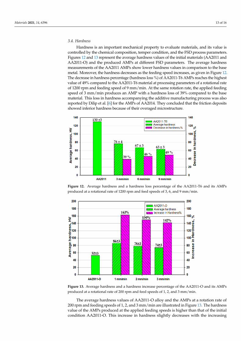
Hardness is an important mechanical property to evaluate materials, and its value iscontrolled by the chemical composition, temper condition, and the FSD process parameters.Figures 12 and 13 represent the average hardness values of the initial materials (AA2011 andAA2011-O) and the produced AMPs at different FSD parameters. The average hardnessmeasurements of the AA2011 AMPs show lower hardness values in comparison to the basemetal. Moreover, the hardness decreases as the feeding speed increases, as given in Figure 12.The decrease in hardness percentage (hardness loss %) of AA2011-T6 AMPs reaches the highestvalue of 49% compared to the AA2011-T6 material at processing parameters of a rotational rateof 1200 rpm and feeding speed of 9 mm/min. At the same rotation rate, the applied feedingspeed of 3 mm/min produces an AMP with a hardness loss of 39% compared to the basematerial. This loss in hardness accompanying the additive manufacturing process was alsoreported by Dilip et al. [6] for the AMPs of AA2014. They concluded that the friction depositsshowed inferior hardness because of their overaged microstructure.
Figure 12. Average hardness and a hardness loss percentage of the AA2011-T6 and its AMPsproduced at a rotational rate of 1200 rpm and feed speeds of 3, 6, and 9 mm/min.
Figure 13. Average hardness and a hardness increase percentage of the AA2011-O and its AMPsproduced at a rotational rate of 200 rpm and feed speeds of 1, 2, and 3 mm/min.
The average hardness values of AA2011-O alloy and the AMPs at a rotation rate of200 rpm and feeding speeds of 1, 2, and 3 mm/min are illustrated in Figure 13. The hardnessvalue of the AMPs produced at the applied feeding speeds is higher than that of the initialcondition AA2011-O. This increase in hardness slightly decreases with the increasing

Materials 2021, 14, 6396 14 of 16
feeding speed. The increase in the hardness value of AMP produced at a 1 mm/minfeeding speed attains 163% compared with the AA2011-O starting material, whereas theimprovement reaches 142% at the applied feeding speed of 3 mm/min.
The high hardness of the as-received AA2011-T6 (130 ± 3 HV) is ascribed to the highinternal stresses stored in the material due to the previous production process, such ascold working. Afterward, the annealing process at 415 ◦C for 2.5 h followed by slowfurnace cooling contributed to the stress relief of the alloy, coarsening, and softening ofthe second phase precipitates. Thus, the hardness of the alloy decreased after annealing,despite the reduction in grain size. It is well known that two mechanisms are controllingthe hardness of this alloy. The first one is the reduction in grain size, which is directlyproportional to the hardness increase. The second one is the morphology and dispersionof the second phase precipitates. In AMPs fabricated using the hard rods of AA2011-T6,the hardness decreased after deposition because the dominant mechanism that affects thehardness was the fragmentation of the hard precipitates. On the contrary, the hardness ofthe AMPs manufactured using the soft AA2011-O rods increased after friction depositionas the dominant mechanism, in this case, was the grain size reduction.
4. Conclusions
The current study investigates the effect of alloy temper conditions on the behaviorupon friction stir deposition. The deposited AMPs were characterized in terms of macroand microstructural features as well as the hardness distribution. Based on the obtainedresults, the following conclusions can be outlined:
• The friction stir deposition technique successfully produced sound continuous multi-layered AA2011 AMPs without any physical discontinuities or interfacial defectsbetween layers along the vertical direction.
• The temper condition of the alloy affects the behavior during FSD, and the parametersthat worked with the T6 condition does not work with the O condition alloy. The hardcondition alloy required high heat input to reach the state of a good deposition, whilethe soft condition alloy required low heat input to reach the FSD state.
• The optimum condition for FSD of AA2011-T6 was a rotational rate of 1200 rpm at feed-ing speeds between 3 and 9 mm/min, while the optimum condition for FSD of AA2011-O was a rotational rate of 200 rpm at feeding speeds between 1 and 3 mm/min.
• Microstructural analysis showed that significant grain refining and intermetallic par-ticle fragmentation have been observed in the AMPs from the two temper condi-tions of AA2011.
• The fine grain formation is mainly dominated by dynamic recrystallization where theaverage grain size is reduced by decreasing the feeding speed at a constant rotationrate. The use of a lower rotation rate resulted in more refining due to the lower heatinput experienced.
• The use of T6 temper alloy has resulted in AMPs with a lower hardness than thestarting material that reached about 61% and 51% of the starting material hardness atfeeding rates of 3 and 9 mm/min, respectively. However, the use of O temper alloyhas resulted in AMPs with higher hardness than the starting material by about 163%hardness enhancement compared to the starting material.
Author Contributions: Conceptualization, M.M.Z.A., E.E. and M.M.E.-S.S.; methodology, M.M.Z.A.,E.E., and M.M.E.-S.S.; software, M.M.E.-S.S. and M.I.A.H.; validation, B.A. and K.T.; formal analysis,M.M.E.-S.S. and M.M.Z.A.; investigation, M.M.E.-S.S. and M.M.Z.A.; resources, B.A. and K.T.; datacuration, M.M.E.-S.S.; writing—original draft preparation, E.E. and M.M.E.-S.S.; writing—review andediting, M.M.E.-S.S. and M.M.Z.A.; visualization, M.I.A.H.; supervision, M.M.Z.A. and M.M.E.-S.S.;project administration, M.M.Z.A. and M.M.E.-S.S.; funding acquisition, B.A. and K.T. All authorshave read and agreed to the published version of the manuscript.
Funding: This research received no external funding.
Institutional Review Board Statement: Not applicable.

Materials 2021, 14, 6396 15 of 16
Informed Consent Statement: Not applicable.
Data Availability Statement: The data presented in this study are available on request from thecorresponding author. The data are not publicly available due to the extremely large size.
Conflicts of Interest: The authors declare no conflict of interest.
References1. Kumar Srivastava, A.; Kumar, N.; Rai Dixit, A. Friction stir additive manufacturing—An innovative tool to enhance mechanical
and microstructural properties. Mater. Sci. Eng. B Solid-State Mater. Adv. Technol. 2021, 263, 114832. [CrossRef]2. Khodabakhshi, F.; Gerlich, A.P.P. Potentials and strategies of solid-state additive friction-stir manufacturing technology: A critical
review. J. Manuf. Process. 2018, 36, 77–92. [CrossRef]3. Zhang, D.; Sun, S.; Qiu, D.; Gibson, M.A.; Dargusch, M.S.; Brandt, M.; Qian, M.; Easton, M. Metal Alloys for Fusion-Based
Additive Manufacturing. Adv. Eng. Mater. 2018, 20, 1–20. [CrossRef]4. Dilip, J.J.S.; Rafi, H.K.; Ram, G.D.J. A new additive manufacturing process based on friction deposition. Trans. Indian Inst. Met.
2011, 64, 27–30. [CrossRef]5. Karthik, G.M.; Ram, G.D.J.; Kottada, R.S. Friction deposition of titanium particle reinforced aluminum matrix composites. Mater.
Sci. Eng. A 2016, 653, 71–83. [CrossRef]6. Dilip, J.J.S.; Ram, G.D.J. Microstructure evolution in aluminum alloy AA 2014 during multi-layer friction deposition. Mater.
Charact. 2013, 86, 146–151. [CrossRef]7. Harun, W.S.W.; Kamariah, M.S.I.N.; Muhamad, N.; Ghani, S.A.C.; Ahmad, F.; Mohamed, Z. A review of powder additive
manufacturing processes for metallic biomaterials. Powder Technol. 2018, 327, 128–151. [CrossRef]8. Singh, S.; Ramakrishna, S.; Singh, R. Material issues in additive manufacturing: A review. J. Manuf. Process. 2017, 25, 185–200.
[CrossRef]9. Rutherford, B.A.; Avery, D.Z.; Phillips, B.J.; Rao, H.M.; Doherty, K.J.; Allison, P.G.; Brewer, L.N.; Brian Jordon, J. Effect of
thermomechanical processing on fatigue behavior in solid-state additive manufacturing of Al-Mg-Si alloy. Metals 2020, 10, 947.[CrossRef]
10. Griffiths, R.J.; Perry, M.E.J.J.; Sietins, J.M.; Zhu, Y.; Hardwick, N.; Cox, C.D.; Rauch, H.A.; Yu, H.Z. A Perspective on Solid-StateAdditive Manufacturing of Aluminum Matrix Composites Using MELD. J. Mater. Eng. Perform. 2019, 28, 648–656. [CrossRef]
11. Dilip, J.J.S.; Babu, S.; Varadha Rajan, S.; Rafi, K.H.; Janaki Ram, G.; Stucker, B.E. Use of friction surfacing for additive manufactur-ing. Mater. Manuf. Process. 2013, 28, 189–194. [CrossRef]
12. Su, J.Q.; Nelson, T.W.; Sterling, C.J. Grain refinement of aluminum alloys by friction stir processing. Philos. Mag. 2006, 86, 1–24.[CrossRef]
13. Gandra, J. Friction stir processing. In Surface Modification by Solid State Processing; Woodhead Publishing: Sawston, UK, 2014; pp.73–111. ISBN 9780857094698.
14. Gupta, G.R.; Parkhurst, J.O.; Ogden, J.A.; Aggleton, P.; Mahal, A. Structural approaches to HIV prevention. Lancet 2008, 372,764–775. [CrossRef]
15. Karthik, G.M.; Panikar, S.; Ram, G.D.J.; Kottada, R.S. Additive manufacturing of an aluminum matrix composite reinforced withnanocrystalline high-entropy alloy particles. Mater. Sci. Eng. A 2017, 679, 193–203. [CrossRef]
16. Andrade, D.G.; Leitão, C.; Rodrigues, D.M. Influence of base material characteristics and process parameters on frictional heatgeneration during Friction Stir Spot Welding of steels. J. Manuf. Process. 2019, 43, 98–104. [CrossRef]
17. Ahmed, M.M.Z.; Ataya, S.; Seleman, M.M.E.S.; Allam, T.; Alsaleh, N.A.; Ahmed, E. Grain structure, crystallographic texture, andhardening behavior of dissimilar friction stir welded aa5083-o and aa5754-h14. Metals 2021, 11, 181. [CrossRef]
18. Guru, P.R.; Khan MD, F.; Panigrahi, S.K.; Ram, G.D.J. Enhancing strength, ductility and machinability of a Al-Si cast alloy byfriction stir processing. J. Manuf. Process. 2015, 18, 67–74. [CrossRef]
19. Jahangir, M.N.; Mamun, M.A.H.; Sealy, M.P. A review of additive manufacturing of magnesium alloys. In AIP ConferenceProceedings; American Institute of Physics Inc.: College Park, MD, USA, 2018; Volume 1980, p. 030026.
20. Mishra, R.S.; Palanivel, S. Building without melting: A short review of friction-based additive manufacturing techniques. Int. J.Addit. Subtractive Mater. Manuf. 2017, 1, 82. [CrossRef]
21. Bose, S.; Ke, D.; Sahasrabudhe, H.; Bandyopadhyay, A. Additive manufacturing of biomaterials. Prog. Mater. Sci. 2018, 93, 45–111.[CrossRef]
22. Palanivel, S.; Nelaturu, P.; Glass, B.; Mishra, R.S.S. Friction stir additive manufacturing for high structural performance throughmicrostructural control in an Mg based WE43 alloy. Mater. Des. 2015, 65, 934–952. [CrossRef]
23. Padhy, G.K.; Wu, C.S.; Gao, S. Friction stir based welding and processing technologies—Processes, parameters, microstructuresand applications: A review. J. Mater. Sci. Technol. 2018, 34, 1–38. [CrossRef]
24. Elfishawy, E.; Ahmed, M.M.Z.; El-Sayed Seleman, M.M. Additive manufacturing of aluminum using friction stir deposition. InTMS 2020 149th Annual Meeting & Exhibition Supplemental Proceedings; The Minerals, Metals & Materials Series; Springer: Cham,Switzerland, 2020. [CrossRef]
25. Boyer, H.E. Heat Treating of Nonferrous Alloys. Metallogr. Microstruct. Anal. 2013, 2, 190–195. [CrossRef]

Materials 2021, 14, 6396 16 of 16
26. Committee, A.H. Heat Treating of Aluminum Alloys. In ASM Handbook, Volume 4: Heat Treating; ASM Handbook Committee:Russell Township, OH, USA, 1991; pp. 841–879. [CrossRef]
27. Ahmed, M.M.Z.; Ataya, S.; El-Sayed Seleman, M.M.; Ammar, H.R.; Ahmed, E. Friction stir welding of similar and dissimilarAA7075 and AA5083. J. Mater. Process. Technol. 2017, 242, 77–91. [CrossRef]
28. Hoziefa, W.; Toschi, S.; Ahmed, M.M.Z.; Morri, A.; Mahdy, A.A.; El-Sayed Seleman, M.M.; El-Mahallawi, I.; Ceschini, L.;Atlam, A. Influence of friction stir processing on the microstructure and mechanical properties of a compocast AA2024-Al2O3nanocomposite. Mater. Des. 2016, 106, 273–284. [CrossRef]
29. Alzahrani, B.; El-Sayed Seleman, M.M.; Ahmed, M.M.Z.; Elfishawy, E.; Ahmed, A.M.Z.; Touileb, K.; Jouini, N.; Habba, M.I.A. TheApplicability of Die Cast A356 Alloy to Additive Friction Stir Deposition at Various Feeding Speeds. Materials 2021, 14, 6018.[CrossRef] [PubMed]
30. Lukács, J.; Meilinger, Á.; Pósalaky, D. High cycle fatigue and fatigue crack propagation design curves for 5754-H22 and 6082-T6aluminium alloys and their friction stir welded joints. Weld. World 2018, 62, 737–749. [CrossRef]
31. Ahmed, M.M.Z.; Ataya, S.; El-Sayed Seleman, M.M.; Mahdy, A.M.A.; Alsaleh, N.A.; Ahmed, E. Heat input and mechanicalproperties investigation of friction stir welded aa5083/aa5754 and aa5083/aa7020. Metals 2021, 11, 1–20.
32. Ahmed, M.M.Z.; Jouini, N.; Alzahrani, B.; Seleman, M.M.E.-S.; Jhaheen, M. Dissimilar Friction Stir Welding of AA2024 and AISI1018: Microstructure and Mechanical Properties. Metals 2021, 11, 330. [CrossRef]
33. Zayed, E.M.; El-Tayeb, N.S.M.; Ahmed, M.M.; Rashad, R.M. Development and Characterization of AA5083 Reinforced with SiCand Al2O3 Particles by Friction Stir Processing. In Engineering Design Applications; Öchsner, A., Altenbach, H., Eds.; SpringerInternational Publishing: Cham, Switzerland, 2019; pp. 11–26. ISBN 978-3-319-79005-3.
34. Hamada, A.S.; Järvenpää, A.; Ahmed, M.M.Z.; Jaskari, M.; Wynne, B.P.; Porter, D.A.; Karjalainen, L.P. The microstructuralevolution of friction stir welded AA6082-T6 aluminum alloy during cyclic deformation. Mater. Sci. Eng. A 2015, 642. [CrossRef]
35. Tonelli, L.; Morri, A.; Toschi, S.; Shaaban, M.; Ammar, H.R.; Ahmed, M.M.Z.; Ramadan, R.M.; El-Mahallawi, I.; Ceschini, L. Effectof FSP parameters and tool geometry on microstructure, hardness, and wear properties of AA7075 with and without reinforcingB4C ceramic particles. Int. J. Adv. Manuf. Technol. 2019, 102, 366–376. [CrossRef]
36. Kang, J.; Feng, Z.C.; Frankel, G.S.; Huang, I.W.; Wang, G.Q.; Wu, A.P. Friction Stir Welding of Al Alloy 2219-T8: Part I-Evolutionof Precipitates and Formation of Abnormal Al2Cu Agglomerates. Metall. Mater. Trans. A Phys. Metall. Mater. Sci. 2016, 47,4553–4565. [CrossRef]
37. Proni, C.T.W.; D’Ávila, M.A.; Zoqui, E.J. Thixoformability evaluation of AA2011 and AA2014 alloys. Int. J. Mater. Res. 2013, 104,1182–1196. [CrossRef]
38. Mishra, R.S.; Ma, Z.Y. Friction stir welding and processing. Mater. Sci. Eng. 2005, 50, 1–78. [CrossRef]39. Rivera, O.G.; Allison, P.G.; Brewer, L.N.; Rodriguez, O.L.; Jordon, J.B.; Liu, T.; Whittington, W.R.; Martens, R.L.; McClelland, Z.;
Mason, C.J.T.; et al. Influence of texture and grain refinement on the mechanical behavior of AA2219 fabricated by high shearsolid state material deposition. Mater. Sci. Eng. A 2018, 724, 547–558. [CrossRef]
40. Fouad, D.M.; El-Garaihy, W.H.; Ahmed, M.M.Z.; Albaijan, I.; Seleman, M.M.E.; Salem, H.G. Grain Structure Evolution andMechanical Properties of Multi-Channel Spiral Twist Extruded AA5083. Metals 2021, 11, 1276. [CrossRef]
41. Rathee, S.; Srivastava, M.; Maheshwari, S.; Kundra, T.K.; Siddiquee, A.N. Friction Based Additive Manufacturing Technologies; CRCPress: Boca Raton, FL, USA, 2018; ISBN 9780815392361.
42. Mishra, R.S.; Mahoney, M.W.; McFadden, S.X.; Mara, N.A.; Mukherjee, A.K. 32-High strain rate superplasticity in a friction stirprocessed 7075 Al alloy. Scr. Mater. 1999, 42, 163–168. [CrossRef]
43. Niclas, Å. A calorimetric analysis and solid-solubility examination of aluminium alloys containing low-melting-point elements.Master’s Thesis, KTH Royal Institute of Technology, Stockholm, Sweden, 2012.
44. Ahmed, M.M.Z.; El-Sayed Seleman, M.M.; Zidan, Z.A.; Ramadan, R.M.; Ataya, S.; Alsaleh, N.A. Microstructure and mechanicalproperties of dissimilar friction stir welded AA2024-T4/AA7075-T6 T-butt joints. Metals 2021, 11, 128. [CrossRef]
45. Zhang, W.W.; Lin, B.; Zhang, D.T.; Li, Y.Y. Microstructures and mechanical properties of squeeze cast Al-5.0Cu-0.6Mn alloys withdifferent Fe content. Mater. Des. 2013, 52, 225–233. [CrossRef]
46. Xu, D.; Zhu, C.; Xu, C.; Chen, K. Microstructures and tensile fracture behavior of 2219 wrought al–cu alloys with differentimpurity of fe. Metals 2021, 11, 174. [CrossRef]
47. Zhang, W.; Lin, B.; Fan, J.; Zhang, D.; Li, Y. Microstructures and mechanical properties of heat-treated Al-5.0Cu-0.5Fe squeezecast alloys with different Mn/Fe ratio. Mater. Sci. Eng. A 2013, 588, 366–375. [CrossRef]