
Assessment of risks posed by chemical industries—application of a new computer automated tool...
15
Journal of Loss Prevention in the Process Industries 12 (1999) 455–469 www.elsevier.com/locate/jlp Assessment of risks posed by chemical industries—application of a new computer automated tool maxcred-III Faisal I. Khan, S.A. Abbasi * Computer Aided Environmental Management Unit, Centre for Pollution Control and Bio-waste Energy, Pondicherry University, Pondicherry, 605 014, India Abstract The paper describes the application of a new computer automated tool, developed by us, in the risk analysis of a typical chemical industry engaged in the manufacture of linear alkyl benzene. Using the tool—a comprehensive software package maxcred-III (MAXimum CREDible accident analysis)—nine different scenarios, one for each storage unit, have been studied. It is observed that the accident scenario for chlorine (instantaneous release followed by dispersion) leads to the largest area-under-lethal-impact, while the accident scenario for propylene (CVCE followed by fireball) forecasts the most intense damage per unit area. The accidents involving propylene, benzene, and fuel oil have a high possibility of causing domino/secondary accidents as their destructive impacts (shock waves, heat load) would envelope other storage and process units. Besides demonstrating the utilizability of maxcred-III, this study also focuses attention on the need to bestow greater effort towards risk assessment/crisis management. The authors hope that the study will highlight the severity of the risk posed by the industry and thus generate safety consciousness among plant managers. The study may also help in developing accident-prevention strategies and the installation of damage control devices. 1999 Elsevier Science Ltd. All rights reserved. Keywords: Maxcred-III; Accidents; Risk assessment 1. Introduction In a recent communication (Khan & Abbasi, 1997a) we have discussed how serious accidents can take place in chemical process industries—in the form of explosions, fires and the release of toxic chemicals. More often than not, such accidents take a heavy toll of pro- perty and human lives. The accidents—if they involve the release of large quantities of toxic chemicals—also contaminate large areas and render them useless for sev- eral years (Lees, 1980; Kletz, 1986). A brief review of some of the recent accidents which have occurred in different industries is presented below to illustrate the myriad ways in which human or equip- ment failures can cause an accident leading to the loss of lives and property (Lees, 1980; Abbasi, Krishnakum- ari & Khan, 1997). * Corresponding author. Tel: 1 91-413-65267/65263; fax: 1 91- 413-65227/65265; e-mail: [email protected] 0950–4230/99/$ - see front matter 1999 Elsevier Science Ltd. All rights reserved. PII:S0950-4230(98)00064-3 2. Illustrative case studies On 21 September 1921, in the evening, two explosions occurred at the Oppau works of Badische Aniline and Sodafabrik (BASF) in the span of 3 s. The explosions created a mammoth crater of 80 m diameter, destroyed the plant, and 700 of the 1000 houses nearby. The explosion was caused by the detonation of some 4500 t of a 50:50 mixture of ammonium sulfate and ammonium nitrate. It was set off by blasting powder, which was being used to break up storage piles of material which had become caked. Exactly the same procedure had been carried out without any mishap some 16 000 times pre- viously! Even houses in the adjacent city of Ludwigshafen and in the Mannheim area were damaged. Walls were dislo- cated and windows broken. At these places and at Heid- elberg, which is about 14 miles from Oppau, the effect of the explosion was first felt by two very heavy earth- quake-like shocks. In Mannheim some seconds later and in Heidelberg 82 s after the shocks there came an enor-
-
Upload
independent -
Category
Documents
-
view
0 -
download
0
Transcript of Assessment of risks posed by chemical industries—application of a new computer automated tool...

Journal of Loss Prevention in the Process Industries 12 (1999) 455–469www.elsevier.com/locate/jlp
Assessment of risks posed by chemical industries—application of anew computer automated toolmaxcred-III
Faisal I. Khan, S.A. Abbasi*
Computer Aided Environmental Management Unit, Centre for Pollution Control and Bio-waste Energy, Pondicherry University, Pondicherry,605 014, India
Abstract
The paper describes the application of a new computer automated tool, developed by us, in the risk analysis of a typical chemicalindustry engaged in the manufacture of linear alkyl benzene. Using the tool—a comprehensive software packagemaxcred-III(MAXimum CREDible accident analysis)—nine different scenarios, one for each storage unit, have been studied. It is observedthat the accident scenario for chlorine (instantaneous release followed by dispersion) leads to the largest area-under-lethal-impact,while the accident scenario for propylene (CVCE followed by fireball) forecasts the most intense damage per unit area. The accidentsinvolving propylene, benzene, and fuel oil have a high possibility of causingdomino/secondaryaccidents as their destructive impacts(shock waves, heat load) would envelope other storage and process units.
Besides demonstrating the utilizability ofmaxcred-III, this study also focuses attention on the need to bestow greater efforttowards risk assessment/crisis management. The authors hope that the study will highlight the severity of the risk posed by theindustry and thus generate safety consciousness among plant managers. The study may also help in developing accident-preventionstrategies and the installation of damage control devices. 1999 Elsevier Science Ltd. All rights reserved.
Keywords:Maxcred-III; Accidents; Risk assessment
1. Introduction
In a recent communication (Khan & Abbasi, 1997a)we have discussed how serious accidents can take placein chemical process industries—in the form ofexplosions, fires and the release of toxic chemicals. Moreoften than not, such accidents take a heavy toll of pro-perty and human lives. The accidents—if they involvethe release of large quantities of toxic chemicals—alsocontaminate large areas and render them useless for sev-eral years (Lees, 1980; Kletz, 1986).
A brief review of some of the recent accidents whichhave occurred in different industries is presented belowto illustrate the myriad ways in which human or equip-ment failures can cause an accident leading to the lossof lives and property (Lees, 1980; Abbasi, Krishnakum-ari & Khan, 1997).
* Corresponding author. Tel:1 91-413-65267/65263; fax:1 91-413-65227/65265; e-mail: [email protected]
0950–4230/99/$ - see front matter 1999 Elsevier Science Ltd. All rights reserved.PII: S0950-4230 (98)00064-3
2. Illustrative case studies
On 21 September 1921, in the evening, two explosionsoccurred at the Oppau works of Badische Aniline andSodafabrik (BASF) in the span of 3 s. The explosionscreated a mammoth crater of 80 m diameter, destroyedthe plant, and 700 of the 1000 houses nearby. Theexplosion was caused by the detonation of some 4500 tof a 50:50 mixture of ammonium sulfate and ammoniumnitrate. It was set off by blasting powder, which wasbeing used to break up storage piles of material whichhad become caked. Exactly the same procedure had beencarried out without any mishap some 16 000 times pre-viously!
Even houses in the adjacent city of Ludwigshafen andin the Mannheim area were damaged. Walls were dislo-cated and windows broken. At these places and at Heid-elberg, which is about 14 miles from Oppau, the effectof the explosion was first felt by two very heavy earth-quake-like shocks. In Mannheim some seconds later andin Heidelberg 82 s after the shocks there came an enor-

456 F.I. Khan, S.A. Abbasi /Journal of Loss Prevention in the Process Industries 12 (1999) 455–469
mous rush of air which broke windows and doors andcaused damage to gas holders, oil tanks, and many riverbarges. The sound of the explosion and the earth shocksreached as far as Bayreuth, at a distance of 145 miles,and the air pressure wave caused considerable damagein Frankfurt, which is about 53 miles from the scene ofthe explosion. The explosion killed 430 people, includ-ing 50 people in the village (Lees, 1980).
On 4 January 1966, a spillage occurred in a refineryin France when an operator was draining water from a1200 m pressurized propane sphere. The propane vapourspread over a radius of 150 m and was ignited by a caron the road. The pool of propane below the sphereengulfed the vessel in flames. The resultant boiling-liquid-expanding-vapour explosion (BLEVE) killed thefireman and 17 others. The conflagration took 48 h tocontrol and caused extensive damage to the refinery.
In June 1974, a 16 in. elbow of a pipe carrying potass-ium carbonate solution in a fertilizer plant at Tamilnadu,India, ruptured suddenly, splashing the hot solution intothe nearby control room. The toughened glass panesshattered; eight persons died in the control room instan-taneously, one died in the hospital and others sustainedgrievous injuries (Lees, 1980).
In March 1984, an explosion in a refinery at Keraladestroyed a fire tender along with the shed wherein itwas housed, besides a chemical warehouse, coolingtower and other facilities. Later investigations revealedmany shortcomings in the plant layout.
On 12 December 1987, a crude oil storage tank in arefinery at Maharashtra, India, started boiling over, spill-ing the contents on the dike around it. Emergency ser-vices and fire brigades, who were alerted, tried to evacu-ate the contents. After 4 h of pumping out, the tankcaught fire and exploded, spilling the contents. Eighthours of vigorous fire fighting had to be carried outbefore the fire could be controlled. There was extensivedamage to the property. A liberal sizing of the dike andproviding a separate dike for a large tank like this wouldhave helped to prevent the spread of fire to other tanks.
An accident took place on 18 April 1989, in a 14 in.natural gas pipeline in a gas company in India. The pipe-line was carrying compressed natural gas at a pressureof about 295–298 psig from the compressor station tovarious consumers. The spot of the accident was about730 ft from the compressor station. A security personnelheard a loud sound at about 09.50 h and saw a hugecloud of black smoke emanating from the ruptured pipe-line which caught fire immediately. The flame rose ashigh as 150 ft during the initial stage.
The fire damaged buildings consisting of the generalstores and the office of the materials department. Twoemployees died and six others received burn injuries.Investigations revealed that the portion of the pipelinewhich had blown off was extensively corroded as com-pared to other portions of the pipeline. The underground
pipeline was close to the materials department where oldlead cells were stored. The corrosion could be due to theleakage of spent weak acid which seeped through theground and corroded the buried pipeline (Kletz, 1986).
2.1. Sao Paulo accident
On 25 February 1984, at least 508 people, most ofthem young children, were killed in Sao Paulo (Brazil)when a 2 ft diameter gasoline pipe ruptured and 700 tonsof gasoline spread across a strip of swamp. The causeof the pipe rupture was not reported, though it was saidto have been brought up to pressure above safe limits.It was also stated that there was no way of monitoringthe pressure in the pipe line (Kletz, 1986).
2.2. Bhopal disaster
In Bhopal, India, the worst-ever disaster in chemicalprocess industries took place on 3 December 1984. Aleak of methyl isocyanate (MIC) from the Union Carbidefactory, where it was used as an intermediate in themanufacture of a pesticide, spread beyond the plantboundary and caused death by poisoning of over 2500people—injuring about 10 times as many.
According to press reports, the contents of the MICstorage tank got overheated and boiled, causing the reliefvalves to lift. The discharge of vapour—about 25 tons—was too great for the capacity of the scrubbing system.The escaping vapour spread beyond the plant boundarywhere a shanty town had sprung up. The cause of theoverheating was contamination of the MIC by water orother materials, and several possible mechanisms weresuggested. According to some reports cyanide was pro-duced. Had Union Carbide conducted risk analysis(specifically maximum credible accident analysis) duringthe design of the MIC system or even later, it wouldhave learnt that in the event of a MIC leak the scrubbingsystem would be inadequate. This would have enabledthe industry to install better emergency handling sys-tems, thereby saving thousands of lives (Abbasi et al.,1997).
2.3. Pepcon explosion
On 4 May 1988, a massive explosion destroyedPacific Engineering and Production Company(PEPCON) plant near Henderson, about 12 miles southof Las Vegas, USA.
2.4. Maharashtra accident
On 5 November 1990, an explosion at the offside bat-tery of compressors at a gas cracking plant in Maharash-tra, India, killed 35 persons, besides causing heavy dam-ages to property and business interruption losses. Among
457F.I. Khan, S.A. Abbasi /Journal of Loss Prevention in the Process Industries 12 (1999) 455–469
the deficiencies in the layout, identified after the disaster,was the location of a contractor’s shed dangerously closeto the gas compressors. Less publicized, but perhaps ofgreater consequence, was the lack of a facility to shutdown the flow of hydrocarbon at the site itself. The plantpersonnel had to run to the control room faster than thevapour that followed them to close the feed valve(Abbasi et al., 1997).
2.5. Visskhapatnam disaster
On 14 September 1997, one of the eight Hortonspheres, filled with LPG/crude/kerosene and situatednear the main gate of the HPCL refinery, caught fire at06.40 h. It then exploded rocking the entire city andmaking people think they had experienced an earth-quake. The second sphere exploded 15 min later andbefore noon the others also caught fire. The tanks wereall full, with crude imports unloaded at the HPCL berthjust a few days ago. Fire spread all over the place.People, particularly those living in the vicinity of therefinery, ran for their lives. As the refinery is located ina densely populated industrial belt with several othermajor industries nearby, a large number of people weredirectly effected by the happenings at HPCL. Huge tong-ues of flames and thick black smoke billowed into thesky and joined the hovering monsoon clouds. A sharpshower brought the soot down on the people who sawtheir white shirts turn black. The rain water flooding theroads was also black and murky.
The death toll which eventually crossed 60 wouldhave been higher had the fire started half-an-hour laterthan it did, when the first shift staff would have comein to relieve the night shift. And Sunday being a holiday,the administrative personnel, who number over 200,were saved as they were not on duty (The Hindu, 1997).
3. Prevention/control of accidents
In view of the serious and ever-increasing risk posedby the chemical process industries as elucidated above,it is necessary to conduct risk assessment (Kayes, 1986;Van Sciver, 1990; Greenberg & Crammer, 1991;Khan & Abbasi, 1995) and develop strategies to preventthe accidents or, if preventive measures fail, to cushiontheir adverse impacts.
Risk assessment involves the following essential steps(Van Sciver, 1990; Green Book, 1992; Khan &Abbasi, 1995):
1. To identify vulnerable spots or ‘high risk’ points inan industry;
2. To simulate accidents and assess the damage theymay cause;
3. To use the results of the previous step in identifying
the priority areas where preventive measures need tobe introduced;
4. To develop disaster management plans based on (2)and (3) above.
It is evident that step (2) is very important in quan-tifying the risk posed. We have, therefore, developedtechniques and tools for conducting risk assessment inthe chemical process industries. These include rapid riskassessment using a computer automated toolmaxcred(Khan & Abbasi, 1996, 1997b, c), and its advanced ver-sionmaxcred-II (Khan & Abbasi, 1997a, d), optimizingHAZOP (hazard and operability study) procedure(Khan & Abbasi, 1997e, f, g), and safety-based design(Khan & Abbasi, 1998).
We have recently enhanced the capabilities ofmaxcred-II in several ways which include (a) the hand-ling of the cascading/domino effect; (b) faster pro-cessing; (c) more efficient error handling; and (d) morevisual appeal. This has been done by employingadvanced concepts of software engineering (event-baseddesign, object oriented data base, etc.). This computerautomated tool enables the quantitative simulation ofaccidents in the chemical process industries. It enablesforecasting of the type of accidents and the types andextent of damage such accidents would cause. Once thisinformation is available by conducting simulations withthe aid ofmaxcred-III, it becomes easy to devise neces-sary accident prevention and damage control strategieson the basis of the characteristics of the industrial site.
4. The software packagemaxcred-III
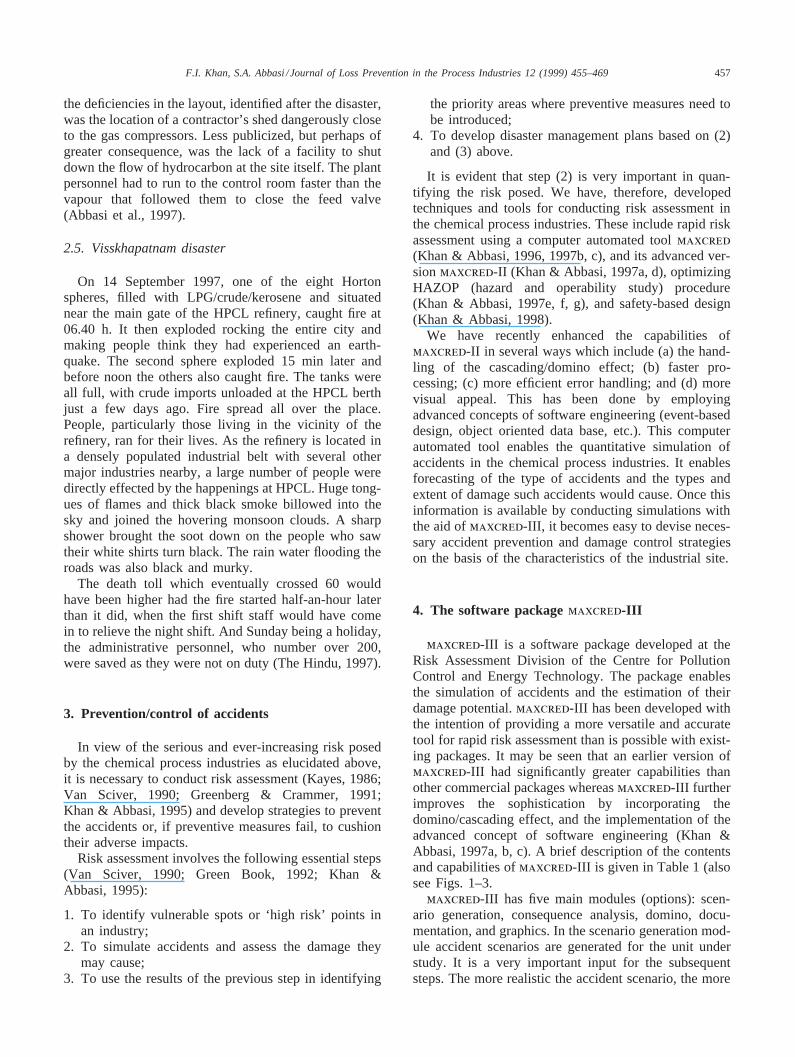
maxcred-III is a software package developed at theRisk Assessment Division of the Centre for PollutionControl and Energy Technology. The package enablesthe simulation of accidents and the estimation of theirdamage potential.maxcred-III has been developed withthe intention of providing a more versatile and accuratetool for rapid risk assessment than is possible with exist-ing packages. It may be seen that an earlier version ofmaxcred-III had significantly greater capabilities thanother commercial packages whereasmaxcred-III furtherimproves the sophistication by incorporating thedomino/cascading effect, and the implementation of theadvanced concept of software engineering (Khan &Abbasi, 1997a, b, c). A brief description of the contentsand capabilities ofmaxcred-III is given in Table 1 (alsosee Figs. 1–3.
maxcred-III has five main modules (options): scen-ario generation, consequence analysis, domino, docu-mentation, and graphics. In the scenario generation mod-ule accident scenarios are generated for the unit understudy. It is a very important input for the subsequentsteps. The more realistic the accident scenario, the more
458 F.I. Khan, S.A. Abbasi /Journal of Loss Prevention in the Process Industries 12 (1999) 455–469
Table 1Software and hardware features ofmaxcred-III
Coding medium: Visual C1 1Working environment: WINDOWSMain menus and system architecture: As in Figs. 1 and 2, respectivelyBasic algorithm: As in Fig. 3System: PC/AT-486 or higherMinimum RAM needed: 4 MBOperating time: The entire accident simulation exercise beginning from keying in the input data to obtaining easy-to-
use tabulated/graphic print-outs is approximately 20 min
Fig. 1. Main submodules ofmaxcred-III.
accurate is the forecast of the type of accident, its conse-quences, and associated risks; consequently more appro-priate and effective are the strategies for crisis aversionand management. Each accident scenario is basically acombination of different likely accidental events thatmay occur in an industry. Such scenarios are generatedbased on the properties of chemicals handled by theindustry, the physical conditions under which reactionsoccur or reactants/products are stored, the geometriesand material strengths of vessel and conduits, in-builtvalves and safety arrangements etc. External factors suchas site characteristics (topography, the presence of trees,ponds, rivers in the vicinity, proximity to other industriesor neighbourhoods, etc.) and meteorological conditionsare also considered.
The consequence analysis module involves the assess-ment of likely consequences if an accident scenario doesmaterialize. The consequences are quantified in terms ofdamage radii (the radii of the area in which the damagewould readily occur), damage to property (shattering ofwindow panes, caving-in of buildings) and toxic effects
(chronic/acute toxicity, mortality). The assessment ofconsequence involves a wide variety of mathematicalmodels. For example, source models are used to predictthe rate of release of hazardous material, the degree offlashing, and the rate of evaporation. Models forexplosions and fires are used to predict the character-istics of explosions and fires. The impact intensity mod-els are used to predict the damage zones due to fires,explosion and toxic load. Lastly, toxic gas models areused to predict human response to different levels ofexposures to toxic chemicals. Several different types ofexplosion and fire models such as confined vapour cloudexplosion (CVCE), unconfined vapour cloud explosion(UVCE), boiling liquid vapour cloud explosion(BLEVE), pool fire, flash fire, jet fire and fireball areincluded. Likewise, models for liquid release and two-phase release have been incorporated. A special featureof maxcred-III is that it is able to handle the dispersionof heavy (heavier-than-air) gases as well as light-as-airand lighter-than-air gases. A brief description of the dif-ferent types of accident events is presented in a sub-sequent section.
459F.I. Khan, S.A. Abbasi /Journal of Loss Prevention in the Process Industries 12 (1999) 455–469
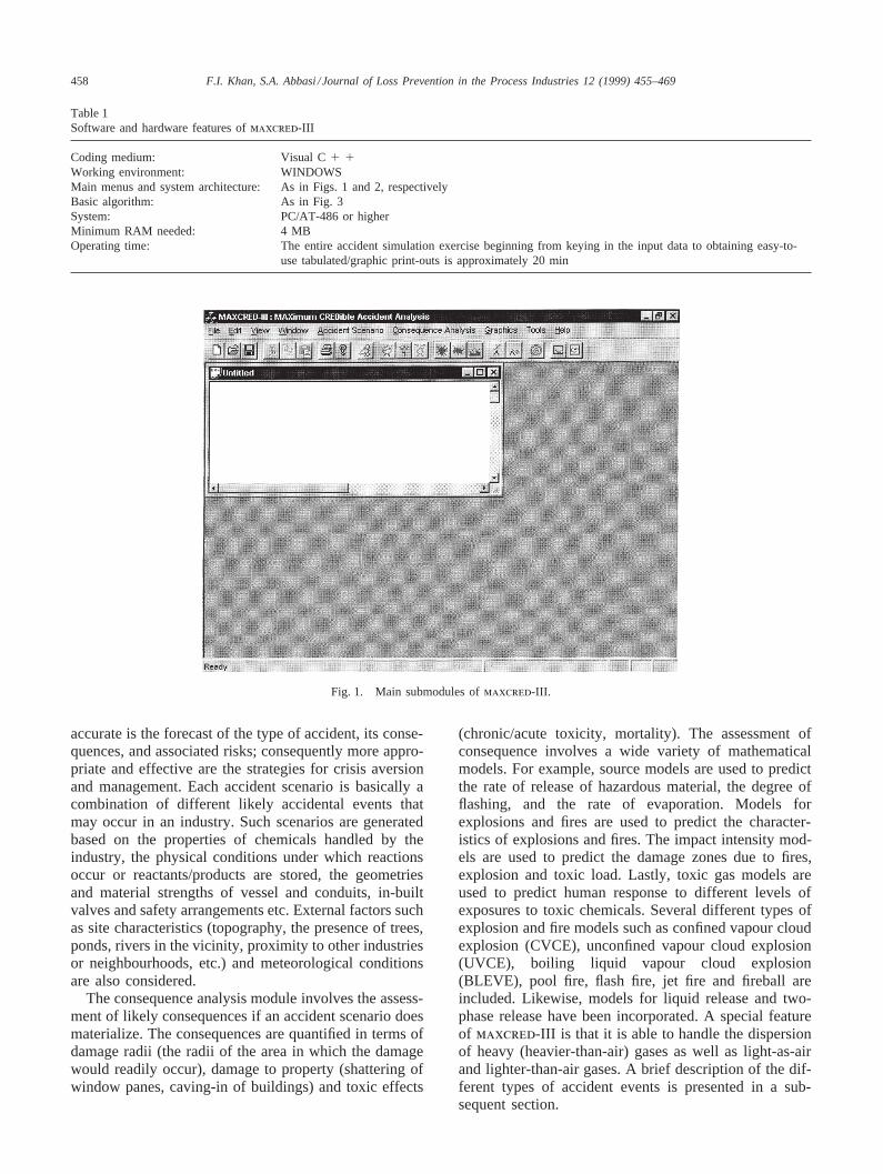
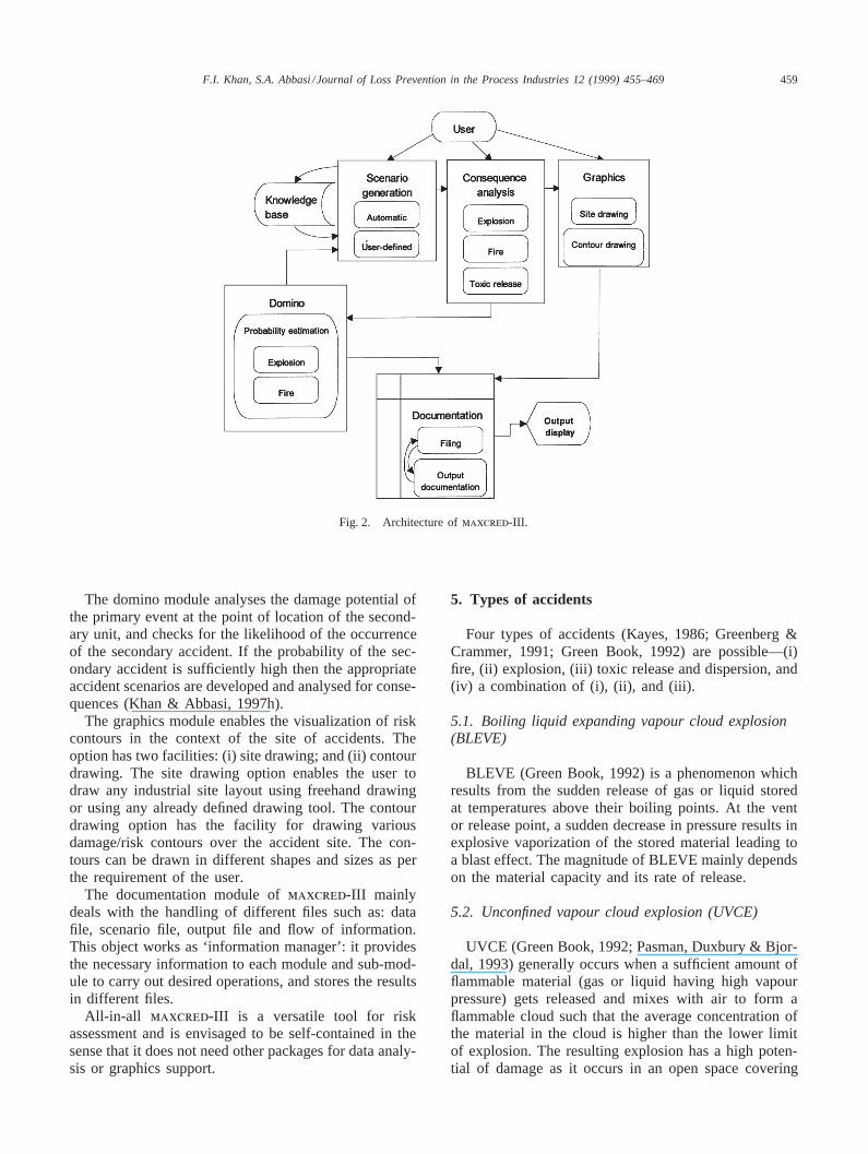
Fig. 2. Architecture ofmaxcred-III.
The domino module analyses the damage potential ofthe primary event at the point of location of the second-ary unit, and checks for the likelihood of the occurrenceof the secondary accident. If the probability of the sec-ondary accident is sufficiently high then the appropriateaccident scenarios are developed and analysed for conse-quences (Khan & Abbasi, 1997h).
The graphics module enables the visualization of riskcontours in the context of the site of accidents. Theoption has two facilities: (i) site drawing; and (ii) contourdrawing. The site drawing option enables the user todraw any industrial site layout using freehand drawingor using any already defined drawing tool. The contourdrawing option has the facility for drawing variousdamage/risk contours over the accident site. The con-tours can be drawn in different shapes and sizes as perthe requirement of the user.
The documentation module ofmaxcred-III mainlydeals with the handling of different files such as: datafile, scenario file, output file and flow of information.This object works as ‘information manager’: it providesthe necessary information to each module and sub-mod-ule to carry out desired operations, and stores the resultsin different files.
All-in-all maxcred-III is a versatile tool for riskassessment and is envisaged to be self-contained in thesense that it does not need other packages for data analy-sis or graphics support.
5. Types of accidents
Four types of accidents (Kayes, 1986; Greenberg &Crammer, 1991; Green Book, 1992) are possible—(i)fire, (ii) explosion, (iii) toxic release and dispersion, and(iv) a combination of (i), (ii), and (iii).
5.1. Boiling liquid expanding vapour cloud explosion(BLEVE)
BLEVE (Green Book, 1992) is a phenomenon whichresults from the sudden release of gas or liquid storedat temperatures above their boiling points. At the ventor release point, a sudden decrease in pressure results inexplosive vaporization of the stored material leading toa blast effect. The magnitude of BLEVE mainly dependson the material capacity and its rate of release.
5.2. Unconfined vapour cloud explosion (UVCE)
UVCE (Green Book, 1992; Pasman, Duxbury & Bjor-dal, 1993) generally occurs when a sufficient amount offlammable material (gas or liquid having high vapourpressure) gets released and mixes with air to form aflammable cloud such that the average concentration ofthe material in the cloud is higher than the lower limitof explosion. The resulting explosion has a high poten-tial of damage as it occurs in an open space covering

460 F.I. Khan, S.A. Abbasi /Journal of Loss Prevention in the Process Industries 12 (1999) 455–469
Fig. 3. Algorithm of maxcred-III.
large areas. The intensity of explosion mainly dependson the quantity of material released and the strength ofthe ignition source.
The explosive power of a UVCE can be expressed interms of blast wave characteristics (overpressure, over-pressure-impulse, reflected pressure, duration of shockwave, etc.). The peak overpressure is a very importantparameter; its magnitude depends on the speed of flamepropagation. Any obstruction in flame propagationenhances the blast effect.
5.3. Confined vapour cloud explosion (CVCE)
CVCE (Green Book, 1992; Pasman et al., 1993;Khan & Abbasi, 1996), as the name suggests, is a vapourexplosion occurring in one or other type of confinement.Explosions in vessels and pipes are examples of CVCE.The excessive generation of high pressure in confine-ment leads to this type of explosion. It also has a highpotential of causing damage as it may generate frag-ments (missiles) propelled at high velocities which cancause further accidents. The energy delivered to the frag-
ments by the blast wave causes the fragments to becomeair-borne and to act as missiles. The missiles are charac-terized by velocity, weight and penetration strength.However, the cumulative effect of CVCE depends uponthe mass of material involved in the explosion and theexplosion pressure.
5.4. Pool fire
The continuous release of flammable liquid results inpool fire (Kayes, 1986; Pitersen, 1990; Green Book,1992). The characteristics of such a fire mainly dependon the duration of release, the saturation pressure, andthe flammable properties of materials.
5.5. Flash fire
Flash fire (Kayes, 1986; Pitersen, 1990) occurs mainlydue to the instantaneous release of a material having aboiling point lower than the atmospheric temperature. Itdoes not explode when the material release rate andflame speed are not high enough. However, it spreads

461F.I. Khan, S.A. Abbasi /Journal of Loss Prevention in the Process Industries 12 (1999) 455–469
quickly throughout the flammable zone of the vapourcloud.
5.6. Jet fires
The burning of a flammable gas issuing from a pipeor other orifice at the point of exit leads to a jet fire.
Jet flames have been involved in a number of acci-dents. Perhaps the most dramatic were the large jetflames from the gas riser at Piper Alpha (Kayes, 1986;Pitersen, 1990; Khan & Abbasi, 1997h).
Jet flames can occur in the chemical process indus-tries, either by design or by accident. They occur inten-tionally in burners and flares. The ejection of flammablefluid from a vessel, pipe or pipe flange can give rise toa jet flame if the material ignites. An intermediate situ-ation, and one which particularly concerns the designer,is where the jet flame results from the ignition of flam-mable material vented from a pressure relief valve. Scen-arios involving jet flames are not easy to handle, sincea large jet flame may have a substantial ‘reach’, some-times up to 50 m or more.
Compared to pool fires and fireballs, jet flames canoccur in more diverse ways. The scenario most oftenconsidered is that of a vertical flame on an upward-point-ing jet, in calm conditions or in wind. But a jet maypoint upwards not vertically but at an angle, in such acase there may be a variety of wind directions, confluentwith, opposed to, or across the jet. There can also be ahorizontal jet, on which the wind may also act in tandem,opposed to it, or across it.
5.7. Fireball
An instantaneous ignition of a flammable vapourcloud would lead to the formation of a fireball (GreenBook, 1992; Pasman et al., 1993; Khan & Abbasi, 1996).The radius of the fireball, its radiation heat intensity, andthe temperature in the fireball depend upon the dimen-sion of the flammable cloud as well as the mass of thevapour released in the cloud. A very high temperatureof 500 to 1500 K is developed in the confines of a fire-ball. It is potentially the most disastrous of industrialfires that may be caused by highly flammable gasesstored or processed under pressure.
The damage associated with such fires may beassessed on the basis of the dose of heat radiationreceived from them in a given time interval.
6. Illustrative example: application of maxcred-III
A risk assessment study has been carried out for achemical industry situated in a congested industrial com-
plex (Fig. 4) engaged in the manufacturing of linearalkyl benzene (LAB) and some byproducts such aschlorinated propylene and chlorohydrine. During themanufacture of LAB, industry deals with various hazard-ous chemicals such as benzene, propylene, n-paraffins,chlorine, and kerosene at elevated temperatures andpressures. The industry and nearby areas are threatenedbecause of different types of hazards (explosion, fire,toxic gaseous release, and corrosive liquid release)present in the industry.
6.1. Brief process description
The raw materials (kerosene, chlorine, n-paraffins,etc.) are stored in tanks in a central tank farm. Kerosene,the main raw material is pumped to the prefractionationunit, where it is preheated and is then fed to the stripperunit. Here, components C9 and less are stripped at thetop and C10 and above are obtained at the bottom. Thebottom stream from the stripper is sent to the rerun col-umn, where C10 to C13 are separated out. These aremixed with hydrogen and sent to the catalytic bed reactorat an elevated temperature. Here, the sulfur, nitrogen,and olefins, which are poisonous to the catalyst, are con-verted into H2S, NH3 and paraffins. The treated feed isthen sent to the Molex unit for the separation of paraf-fins. The normal and non-normal paraffins thus obtainedare purified by the extraction process. The normal paraf-fins are then sent to the Pacol unit, where they are dehy-drogenated at elevated temperatures (480°C) over a cata-lyst bed of platinum (Pt) on alumina. The crackedproducts are separated in a stripper column and passedon to the alkylation unit. Benzene is added to the mono-olefins in the presence of hydrofluoric acid, which cata-lyses the reaction to form linear alkyl benzene and otherproducts. The main units of linear alkyl benzene plantsare listed in Table 2.
We have conducted a risk analysis of the entire plant.In order to optimize the time and effort, a hazard identi-fication and ranking exercise was first carried out. Theexercise is meant to identify the type of hazards presentand a rough estimation of their hazard potential. Theunits are accordingly characterized and ranked in priorityfor the comprehensive study. Dow’s Fire and ExplosionIndex (AIChE, 1994) has been used for this step, and asummary of results thus obtained are presented in Fig.5. It is clear from the figure that the storage of propylene,benzene, and chlorine are the most hazardous, followedby the storage of kerosene, fuel oil, n-paraffins, andallylchloride. Other process units: Pacol, alkylation, hyd-rotreater, Molex, and chlorohydrination are compara-tively less hazardous. All these units have been furthersubjected tomaxcred-III for hazard assessment anddamage potential estimation.
For the sake of brevity, the present paper gives details

462 F.I. Khan, S.A. Abbasi /Journal of Loss Prevention in the Process Industries 12 (1999) 455–469
Fig. 4. Layout of the study area showing location of industry and their surroundings.
Table 2The main units of linear alkyl benzene (LAB) plant
Units Reference used Operationin Fig. 5
Prefractionation unit A FractionationRerun column B FractionationStripping unit C SeparationHydrotreater unit D ReactionMolex unit E Extractive separationPacol unit F ReactionAlkylation unit G ReactionPropylene chlorination H ReactionAllylchloride purification I FractionationChlorine absorption in J AbsorptionwaterChlorohydrination K ReactionPropylene bullets L StorageChlorohydrine M StorageFuel oil tanks N StorageChlorinated organic tanks O StorageChlorine storage P StorageBenzene storage Q Storagen-Paraffin storage R StorageKerosine storage S Storage
of the study of only the most hazardous units in the plant(storage unit).
The storage unit comprises of the vessels storing vari-ous chemicals at elevated temperatures and pressures
Fig. 5. Damage potential of different units in linear alkyl benzeneplant. See Table 1 for explanations of A, B, … S.

463F.I. Khan, S.A. Abbasi /Journal of Loss Prevention in the Process Industries 12 (1999) 455–469
(Table 3). Each storage vessel (for each hazardouschemical) has been subjected tomaxcred-III for hazardassessment and damage potential quantification. Tofacilitate the understanding of the use ofmaxcred-III,the results of the study are presented in steps that followthe algorithm ofmaxcred-III.
6.2. Accident scenarios generation
Based on the history of major accidents in processindustries and the authors’ experience, the followingscenarios have been visualized for accidents in differentstorage units (Pitersen, 1990; Green Book, 1992; Pasmanet al., 1993; Khan & Abbasi, 1996, 1997a, b, c, i).
6.2.1. Propylene storage: scenario 1An excessive pressure development in the storage ves-
sel of propylene (under high pressure and temperature)leads to confined vapour cloud explosion (CVCE). Thevapour cloud generated by CVCE on ignition turns intoa fireball and consequently damages the other storagevessels (chlorine, allylchloride, benzene, paraffins, fueloil).
6.2.2. Chlorine storage: scenario 2A sudden release of pressurized chlorine triggers a
boiling liquid expanding vapour explosion (BLEVE) andthe dispersion of a toxic vapour cloud; in other wordsexplosive release followed by toxic dispersion (Khan &Abbasi, 1997b, c).
6.2.3. N-Paraffin storage: scenario 3An unconfined vapour cloud explosion (UVCE)
occurs in the n-paraffin unit accompanied by a pool fire.This can happen if a small leak in the storage vesselreleases material at a moderate flow rate and forms avapour cloud in the atmosphere, which on ignition leadsto UVCE. Due to the heat generated by UVCE or by anexternal source of ignition the remaining material in thevessel or dike catches fire causing a pool fire. A UVCEfollowed by a pool fire can damage neighbouring vessels
Table 3Operating conditions of different storage units
Hazardous chemicals No. of tanks Capacity of each tank Operating pressure Operating temperature(ton/m3) (atm) (°C)
Benzene 2 400 m3 4.55 40Normal paraffin 2 200 T 2.15 25Propylene 2 60 T 15.20 40Chlorine 2 100 m3 4.25 20Allychloride 2 50 m3 1.00 35Kerosene 2 450 m3 1.15 30Fuel oil 1 400 m3 1.00 40Chlorohydrine 1 100 m3 1.22 40Chlorinated organics 2 200 m3 1.22 40
due to excess shock waves and heat load, and can triggersecondary and higher order accidents.
6.2.4. Allylchloride storage: scenario 4Instantaneous release followed by pool fire in the
allylchloride storage unit.
6.2.5. Fuel oil storage: scenario 5There is a pool fire in the fuel oil storage unit.
6.2.6. Chlorohydrine and chlorinated organic storage:scenarios 6 and 7
The release of chlorohydrine and chlorinated organicis followed by evaporation and a pool fire.
6.2.7. Benzene storage: scenario 8An excessive high pressure development in the stor-
age vessel of benzene leads to BLEVE (maximumreported incidents). The unburned vapour cloud releaseddue to explosion on ignition leads to a fireball.
6.2.8. Kerosene storage: scenario 9An instantaneous release of kerosene (due to high
pressure development) either through a vent valve orthrough any accidental opening causes the vessel toexplode in the manner of a BLEVE. As the releasedchemical is flammable it turns to a flash fire on meetingan ignition source.
These scenarios have been processed for damage esti-mation throughmaxcred-III.
6.3. Hazard quantification
The results of the calculations for different accidentscenarios are summarized below.
As per scenario 1 (Table 4) the missiles generated byCVCE may hit nearby targets and can lead to secondaryexplosions or toxic releases. The CVCE vapour cloudon ignition may cause a fireball and hence severe heatradiation load. The shock wave from the CVCE cancause injury as well as second order accidents by seri-
464 F.I. Khan, S.A. Abbasi /Journal of Loss Prevention in the Process Industries 12 (1999) 455–469
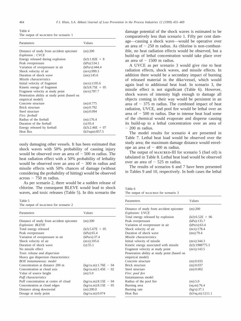
Table 4The output ofmaxcred for scenario 1
Parameters Values
Distance of study from accident epicenter (m):200Explosion : CVCEEnergy released during explosion (kJ):1.82E1 8Peak overpressure (kPa):534.1Variation of overpressure in air (kPa/s):444.4Shock velocity of air (m/s):999.3Duration of shock wave (ms):145.6Missile characteristicsInitial velocity of fragment (m/s):1195.6Kinetic energy of fragment (kJ):8.75E1 05Fragment velocity at study point (m/s):787.7Penetration ability at study point (based onempirical model)Concrete structure (m):0.775Brick structure (m):0.792Steel structure (m):0.094Fire: fireballRadius of the fireball (m):176.4Duration of the fireball (s):93.4Energy released by fireball (kJ):2.46E1 07Heat flux (kJ/sqm):857.5
ously damaging other vessels. It has been estimated thatshock waves with 50% probability of causing injurywould be observed over an area of| 500 m radius. Theheat radiation effect with a 50% probability of lethalitywould be observed over an area of| 300 m radius andmissile effects with 50% chances of damage (withoutconsidering the probability of hitting) would be observedacross| 750 m radius.
As per scenario 2, there would be a sudden release ofchlorine. The consequent BLEVE would lead to shockwaves, and toxic releases (Table 5). In this scenario the
Table 5The output ofmaxcred for scenario 2
Parameters Values
Distance of study from accident epicenter (m):200Explosion: BLEVETotal energy released (kJ):5.67E1 05Peak overpressure (kPa):65.4Variation of overpressure in air (kPa/s):37.4Shock velocity of air (m/s):105.6Duration of shock wave (s):55.1No missile effectToxic release and dispersionHeavy gas dispersion characteristicsBOX instantaneous: modelConcentration at distance 200 m (kg/cu.m):1.76E2 04Concentration at cloud axis (kg/cu.m):1.45E2 02Value of source height (m):5.0Puff characteristicsPuff concentration at centre of cloud (kg/cu.m):8.15E2 04Concentration at cloud edges (kg/cu.m):8.15E2 05Distance along downwind (m):200.0Dosage at study point (kg/cu.m):0.074
damage potential of the shock waves is estimated to becomparatively less than scenario 1. Fifty per cent dam-age—causing a shock wave—would be operative overan area of| 250 m radius. As chlorine is non-combust-ible, no heat radiation effects would be observed, but abuild-up of lethal concentration would take place overan area of| 1500 m radius.
A UVCE as per scenario 3 would give rise to heatradiation effects, shock waves, and missile effects. Inaddition there would be a secondary impact of burningof released material in the dike/vessel, which wouldagain lead to additional heat load. In scenario 3, themissile effect is not significant (Table 6). However,shock waves of intensity high enough to damage allobjects coming in their way would be persistent in anarea of| 375 m radius. The combined impact of heatradiation, UVCE, and pool fire would be lethal over anarea of| 500 m radius. Due to intense heat load someof the chemical would evaporate and disperse causingits build-up to a lethal concentration over an area of| 200 m radius.
The model results for scenario 4 are presented inTable 7. Lethal heat load would be observed over thestudy area; the maximum damage distance would envel-ope an area of| 400 m radius.
The output ofmaxcred-III for scenario 5 (fuel oil) istabulated in Table 8. Lethal heat load would be observedover an area of| 525 m radius.
The results of scenarios 6 and 7 have been presentedin Tables 9 and 10, respectively. In both cases the lethal
Table 6The output ofmaxcred for scenario 3
Parameters Values
Distance of study from accident epicenter (m):200Explosion: UVCETotal energy released by explosion (kJ):6.52E1 06Peak overpressure (kPa):135.7Variation of overpressure in air (kPa/s):63.4Shock velocity of air (m/s):178.4Duration of shock wave (ms):79.4Missile characteristicsInitial velocity of missile (m/s):344.3Kinetic energy associated with missile (kJ):1988775.3Fragment velocity at study point (m/s):143.5Penetration ability at study point (based onempirical model)Concrete structure (m):0.035Brick structure (m):0.037Steel structure (m):0.002Fire: pool fireInstantaneous modelRadius of the pool fire (m):5.0Burning area (sq.m):76.4Burning rate (kg/s):37.1Heat flux (kJ/sq.m):1211.1

465F.I. Khan, S.A. Abbasi /Journal of Loss Prevention in the Process Industries 12 (1999) 455–469
Table 7The output ofmaxcred for scenario 4
Parameters Values
Distance of study from accident epicenter (m):200Fire: pool fireContinuous modelBurning area (sq.m):77.0Burning rate (kg/h):15314.9Heat flux (kJ/sq.m):994.7
Table 8The output ofmaxcred for scenario 5
Parameters Values
Distance of study from accident epicenter (m):200Fire: pool fireInstantaneous modelRadius of the pool fire (m):5.0Burning area (sq.m):71.1Burning rate (kg/s):36.2Heat flux (kJ/sq.m):1210.0
Table 9The output ofmaxcred for scenario 6
Parameters Values
Distance of study from accident epicenter (m):200Fire: pool fireContinuous modelBurning area (sq.m):77.0Burning rate (kg/h):12253.7Heat flux (kJ/sq.m):385.5
Table 10The output ofmaxcred for scenario 7
Parameters Values
Distance of study from accident epicenter (m):200Fire: pool fireContinuous modelBurning area (sq.m):77.0Burning rate (kg/h):13144.3Heat flux (kJ/sq.m):477.6
heat load (50% chance of fatality) is confined to an areaof | 200 m radius.
As per scenario 8 BLEVE would generate shockwaves as well as missiles. In addition, there would besecondary impact of the released material getting ignitedand forming a fireball, thereby generating additional heatload. The output ofmaxcred-III for this scenario is
Table 11The output ofmaxcred for scenario 8
Parameters Values
Distance of study from accident epicenter (m):200Explosion: BLEVEEnergy released during explosion (kJ):1.13E1 08Peak overpressure (kPa):499.5Variation of overpressure in air (kPa/s):378.7Shock velocity of air (m/s):876.4Duration of shock wave (ms):110.5Missile characteristicsInitial velocity of fragment (m/s):957.4Kinetic energy of fragment (kJ):6.57E1 05Fragment velocity at study point (m/s):606.4Penetration ability at study point (based onempirical model)Concrete structure (m):0.624Brick structure (m):0.691Steel structure (m):0.064Fire: fireballRadius of the fireball (m):115.04Duration of the fireball (s):75.45Energy released by fireball (kJ):1.18E1 07Heat flux (kJ/sqm):765.5
presented in Table 11. The lethal impact of shock waves,heat load, and missiles would go up to and beyond aradius of| 350 m.
The instantaneous failure of (boiling liquid expandingvapour explosion) a kerosene tank as per scenario 9would generate shock waves and missiles (Table 12).The released chemical on meeting the ignition sourcewould generate heat load (flash fire). The heat load hav-ing the propensity to cause damage would be observedover an area of| 250 m radius.
6.4. Risk estimation
The individual risk factors for fatality have been esti-mated using the results obtained bymaxcred-III and the
Table 12The output ofmaxcred for scenario 9
Parameters Values
Distance of study from accident epicenter (m):200Explosion: BLEVETotal energy released (kJ):5.45E1 05Peak overpressure (kPa):62.6Variation of overpressure in air (kPa/s):35.1Shock velocity of air (m/s):97.4Duration of shock wave (ms):47.1No missile effectFire: flash fireVolume of vapor cloud (cu.m):11629.2Duration of fire (s):3876.3Heat flux (kJ/sq.m):441.9

466 F.I. Khan, S.A. Abbasi /Journal of Loss Prevention in the Process Industries 12 (1999) 455–469
probability of occurrence of the accident scenarios, indi-vidual fatal risk factors have been estimated (Kletz,1986; Contini, Amendola & Ziomas, 1991; EuropeanCommunity, 1992; Reliability Directorate, 1992). Therisk factor is a direct representation of the threat (takinginto consideration both damage potential and the prob-ability of occurrence) to an individual in an area.
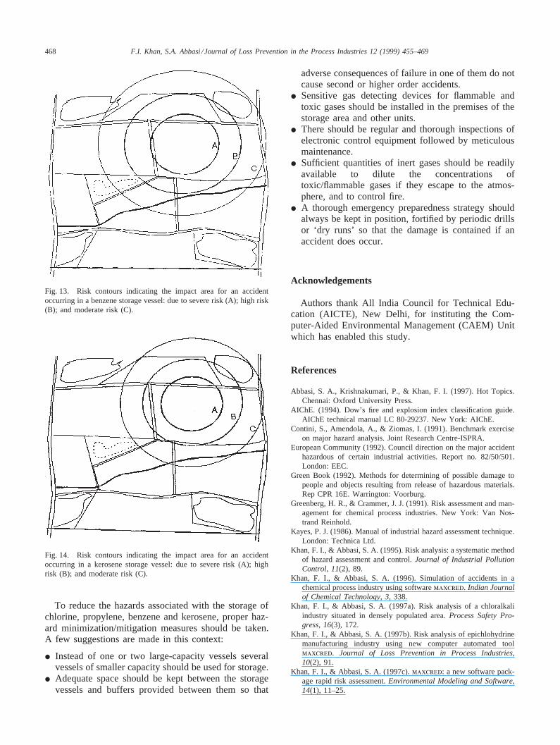
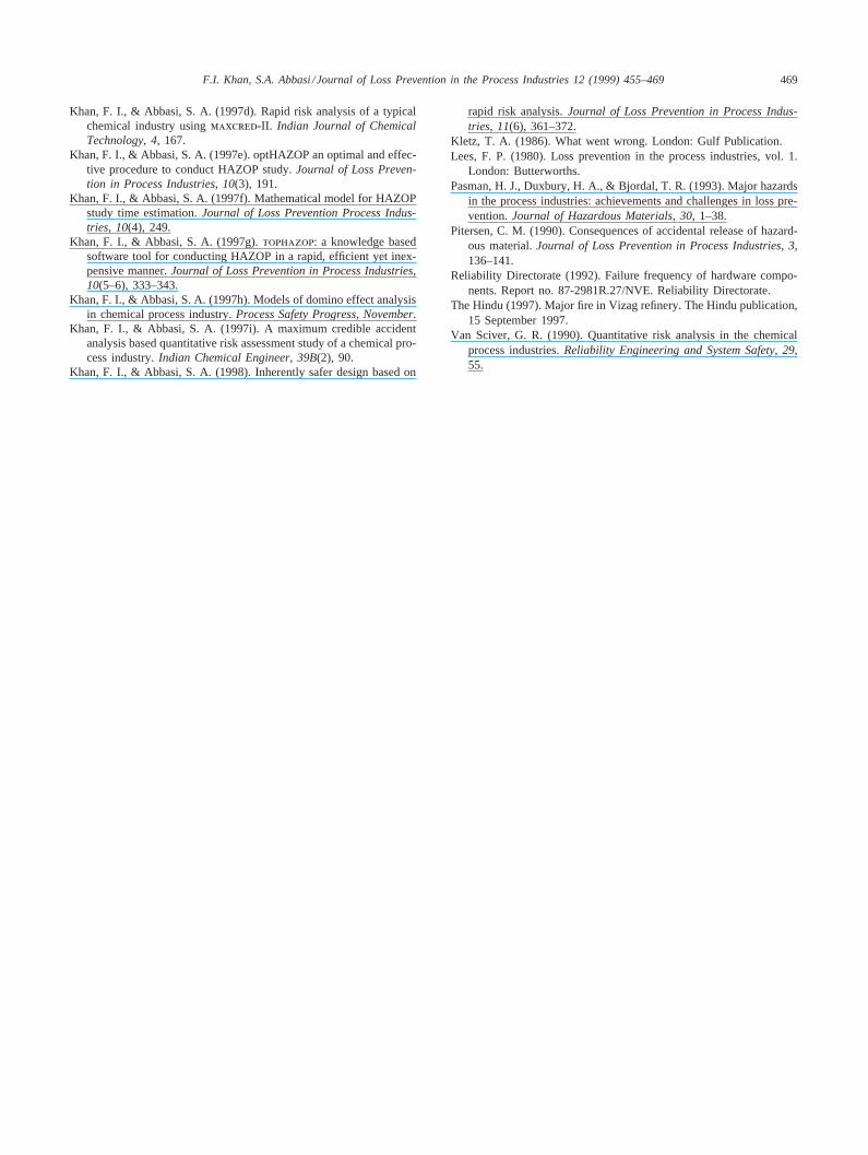
In order to enable the visualization of accident scen-arios, their risk contours have been drawn over the studyarea (Figs. 6–14). It may be seen that the risk contoursfor scenarios 1 to 3, (Figs. 6–8) are extending beyondthe boundaries of the industry and enveloping otherindustries and nearby populated areas. The risk contoursfor scenarios 4 to 7 are confined to the campus of theplant (Figs. 9–12). The risk contours for scenarios 8 and9 extend beyond the boundary of the factory (Figs. 13and 14) and encompasses other industries (storage ves-sels of other industries). This may cause secondary acci-dents, the impacts of which may go beyond the industrialcomplex premise.
In summary, scenario 2 represents the worst likely dis-aster within the realm of credibility. It has the largestarea-of-lethal-impact (shock wave over an area of radius| 200 m and lethal concentration across an area of radius| 1500 m). Furthermore, the most thickly populatedareas (including the residential areas of Kharagpur andDhorala) lie within its range. If one considers the cumu-lative effects, scenarios 1 and 8 would come out as theworst, as more intense impacts (in terms of heat radi-ation, shock waves, and missiles) are observed per unitarea in these scenarios. Of the nine most credible scen-arios, scenarios 1 and 8 are the most likely to cause cas-
Fig. 6. Risk contours indicating the impact area for an accidentoccurring in a propylene storage vessel: due to severe risk (A); highrisk (B); and moderate risk (C).
Fig. 7. Risk contours indicating the impact area for an accidentoccurring in a chlorine storage vessel: due to severe risk (A); high risk(B); and moderate risk (C).
Fig. 8. Risk contours indicating the impact area for an accidentoccurring in a paraffin storage vessel: due to severe risk (A); high risk(B); and moderate risk (C).
cading effects, as missiles, shock waves, and radiationeffects would be generated simultaneously and otherindustries or units dealing with flammable and toxicmaterials are situated within the striking distance of theprimary accident. Scenarios 3, 4, 5 and 9 also have thepotential to lead to secondary accidents, as severe heatload generated in these would encompass other storagevessels. All-in-all, scenario 2 is the worst as far as pri-mary effects are concerned, whereas scenarios 1 and 8

467F.I. Khan, S.A. Abbasi /Journal of Loss Prevention in the Process Industries 12 (1999) 455–469
Fig. 9. Risk contours indicating the impact area for an accidentoccurring in an allylchloride storage vessel: due to severe risk (A);high risk (B); and moderate risk (C).
Fig. 10. Risk contours indicating the impact area for an accidentoccurring in a fuel oil storage vessel: due to severe risk (A); high risk(B); and moderate risk (C).
are the worst in terms of their potentiality of causingcascading (domino) effects.
7. Conclusion
A new software packagemaxcred-III has beendeveloped for performing quantitative risk analysis. Thepackage generates different credible accident scenarios,and quantifies the damage they can cause. This infor-mation can then be used in developing strategies for pre-venting accidents and to dampen their adverse impactsif the accidents do take place.
Fig. 11. Risk contours indicating the impact area for an accidentoccurring in a chlorohydrine storage vessel: due to severe risk (A);high risk (B); and moderate risk (C).
Fig. 12. Risk contours indicating the impact area for an accidentoccurring in a chlorinated hydrocarbon storage vessel: due to severerisk (A); high risk (B); and moderate risk (C).
The applicability ofmaxcred-III has been illustratedwith a case study of a linear alkyl benzene manufactur-ing industry situated in Suretgarh, Uttar Pradesh, India.In the first step—hazard identification and ranking—storage and process units involving chlorination, chlo-rohydration, and quenching were identified as the mostvulnerable vis-a`-vis the propensity of causing accidents.A detailed study of the credible accidents in storage unitsand their impacts was then carried out with the help ofmaxcred-III. The studies reveal that the storage units ofpropylene, benzene, chlorine, kerosene, and n-paraffinare the most hazardous, and accidents in these units maycause severe damage to the factory and its surroundings.
468 F.I. Khan, S.A. Abbasi /Journal of Loss Prevention in the Process Industries 12 (1999) 455–469
Fig. 13. Risk contours indicating the impact area for an accidentoccurring in a benzene storage vessel: due to severe risk (A); high risk(B); and moderate risk (C).
Fig. 14. Risk contours indicating the impact area for an accidentoccurring in a kerosene storage vessel: due to severe risk (A); highrisk (B); and moderate risk (C).
To reduce the hazards associated with the storage ofchlorine, propylene, benzene and kerosene, proper haz-ard minimization/mitigation measures should be taken.A few suggestions are made in this context:
I Instead of one or two large-capacity vessels severalvessels of smaller capacity should be used for storage.
I Adequate space should be kept between the storagevessels and buffers provided between them so that
adverse consequences of failure in one of them do notcause second or higher order accidents.
I Sensitive gas detecting devices for flammable andtoxic gases should be installed in the premises of thestorage area and other units.
I There should be regular and thorough inspections ofelectronic control equipment followed by meticulousmaintenance.
I Sufficient quantities of inert gases should be readilyavailable to dilute the concentrations oftoxic/flammable gases if they escape to the atmos-phere, and to control fire.
I A thorough emergency preparedness strategy shouldalways be kept in position, fortified by periodic drillsor ‘dry runs’ so that the damage is contained if anaccident does occur.
Acknowledgements
Authors thank All India Council for Technical Edu-cation (AICTE), New Delhi, for instituting the Com-puter-Aided Environmental Management (CAEM) Unitwhich has enabled this study.
References
Abbasi, S. A., Krishnakumari, P., & Khan, F. I. (1997). Hot Topics.Chennai: Oxford University Press.
AIChE. (1994). Dow’s fire and explosion index classification guide.AIChE technical manual LC 80-29237. New York: AIChE.
Contini, S., Amendola, A., & Ziomas, I. (1991). Benchmark exerciseon major hazard analysis. Joint Research Centre-ISPRA.
European Community (1992). Council direction on the major accidenthazardous of certain industrial activities. Report no. 82/50/501.London: EEC.
Green Book (1992). Methods for determining of possible damage topeople and objects resulting from release of hazardous materials.Rep CPR 16E. Warrington: Voorburg.
Greenberg, H. R., & Crammer, J. J. (1991). Risk assessment and man-agement for chemical process industries. New York: Van Nos-trand Reinhold.
Kayes, P. J. (1986). Manual of industrial hazard assessment technique.London: Technica Ltd.
Khan, F. I., & Abbasi, S. A. (1995). Risk analysis: a systematic methodof hazard assessment and control.Journal of Industrial PollutionControl, 11(2), 89.
Khan, F. I., & Abbasi, S. A. (1996). Simulation of accidents in achemical process industry using softwaremaxcred. Indian Journalof Chemical Technology, 3, 338.
Khan, F. I., & Abbasi, S. A. (1997a). Risk analysis of a chloralkaliindustry situated in densely populated area.Process Safety Pro-gress, 16(3), 172.
Khan, F. I., & Abbasi, S. A. (1997b). Risk analysis of epichlohydrinemanufacturing industry using new computer automated toolmaxcred. Journal of Loss Prevention in Process Industries,10(2), 91.
Khan, F. I., & Abbasi, S. A. (1997c).maxcred: a new software pack-age rapid risk assessment.Environmental Modeling and Software,14(1), 11–25.
469F.I. Khan, S.A. Abbasi /Journal of Loss Prevention in the Process Industries 12 (1999) 455–469
Khan, F. I., & Abbasi, S. A. (1997d). Rapid risk analysis of a typicalchemical industry usingmaxcred-II. Indian Journal of ChemicalTechnology, 4, 167.
Khan, F. I., & Abbasi, S. A. (1997e). optHAZOP an optimal and effec-tive procedure to conduct HAZOP study.Journal of Loss Preven-tion in Process Industries, 10(3), 191.
Khan, F. I., & Abbasi, S. A. (1997f). Mathematical model for HAZOPstudy time estimation.Journal of Loss Prevention Process Indus-tries, 10(4), 249.
Khan, F. I., & Abbasi, S. A. (1997g).tophazop: a knowledge basedsoftware tool for conducting HAZOP in a rapid, efficient yet inex-pensive manner.Journal of Loss Prevention in Process Industries,10(5–6), 333–343.
Khan, F. I., & Abbasi, S. A. (1997h). Models of domino effect analysisin chemical process industry.Process Safety Progress, November.
Khan, F. I., & Abbasi, S. A. (1997i). A maximum credible accidentanalysis based quantitative risk assessment study of a chemical pro-cess industry.Indian Chemical Engineer, 39B(2), 90.
Khan, F. I., & Abbasi, S. A. (1998). Inherently safer design based on
rapid risk analysis.Journal of Loss Prevention in Process Indus-tries, 11(6), 361–372.
Kletz, T. A. (1986). What went wrong. London: Gulf Publication.Lees, F. P. (1980). Loss prevention in the process industries, vol. 1.
London: Butterworths.Pasman, H. J., Duxbury, H. A., & Bjordal, T. R. (1993). Major hazards
in the process industries: achievements and challenges in loss pre-vention.Journal of Hazardous Materials, 30, 1–38.
Pitersen, C. M. (1990). Consequences of accidental release of hazard-ous material.Journal of Loss Prevention in Process Industries, 3,136–141.
Reliability Directorate (1992). Failure frequency of hardware compo-nents. Report no. 87-2981R.27/NVE. Reliability Directorate.
The Hindu (1997). Major fire in Vizag refinery. The Hindu publication,15 September 1997.
Van Sciver, G. R. (1990). Quantitative risk analysis in the chemicalprocess industries.Reliability Engineering and System Safety, 29,55.