Assembly for ARM
15
– 21 – Experiment 2: Introduction to Assembly Language Programming This experiment is the gateway to all that you do in this course, both inside and outside the Laboratory. It lays the foundation for everything that is to come in the programmer’s view of computer architecture, showing you some important principles and guiding you through some of the details of programming for microcontroller-based systems. Aims This experiment aims to: introduce simple ARM assembly language instructions, show the process of hand-compilation from C to assembly language, show the programmer’s view of the register and memory, show the basics of writing and debugging assembly language program for the ARM microprocessor, and teach you “best practice” techniques for formatting your code (also known as program- ming style rules). Preparation It is important that you prepare for each laboratory experiment, so that you can use your time (and your partner’s time) most effectively. For this particular experiment, you should do the following before coming in to the Laboratory: get your own copy of this Laboratory Manual, as well as the accompanying CD-ROM, read through this experiment in detail, trying to understand what you will be doing, quickly read through the relevant material from your lecture notes for this course, and quickly skim through An Introduction to the GNU Assembler and An Introduction to the GNU Debugger. You can find these documents on your CD-ROM. If you are keen (and you should be!), you could also: browse through the Companion CD-ROM, install the software on the CD-ROM onto your computer at home, type up or modify the necessary files in this experiment, to save time in class, and run through the experiment at home using the simulator. Getting Started Once you arrive at the Laboratory, find a spare workbench and log into the Host PC. Next, create a new directory for this experiment. Then, copy all of the files in the directory ~elec2041/ unsw/elec2041/labs-src/exp2 on the Laboratory computers into this new directory. You can do all of this by opening a Unix command-line shell window and entering: mkdir ~/exp2 cd ~/exp2 cp ~elec2041/cdrom/unsw/elec2041/labs-src/exp2/* . Be careful to note the “.” at the end of the cp command! If you are doing this experiment at home, you will not have a ~elec2041 directory, of course. You should use the unsw/elec2041/labs-src/exp2 directory on your CD-ROM instead.
-
Upload
independent -
Category
Documents
-
view
0 -
download
0
Transcript of Assembly for ARM
– 21 –
Experiment 2:Introduction to Assembly Language Programming
This experiment is the gateway to all that you do in this course, both inside and outside theLaboratory. It lays the foundation for everything that is to come in the programmer’s viewof computer architecture, showing you some important principles and guiding you throughsome of the details of programming for microcontroller-based systems.
Aims
This experiment aims to:
introduce simple ARM assembly language instructions,
show the process of hand-compilation from C to assembly language,
show the programmer’s view of the register and memory,
show the basics of writing and debugging assembly language program for the ARMmicroprocessor, and
teach you “best practice” techniques for formatting your code (also known as program-ming style rules).
Preparation
It is important that you prepare for each laboratory experiment, so that you can use yourtime (and your partner’s time) most effectively. For this particular experiment, you shoulddo the following before coming in to the Laboratory:
get your own copy of this Laboratory Manual, as well as the accompanying CD-ROM,
read through this experiment in detail, trying to understand what you will be doing,
quickly read through the relevant material from your lecture notes for this course, and
quickly skim through An Introduction to the GNU Assembler and An Introduction to theGNU Debugger. You can find these documents on your CD-ROM.
If you are keen (and you should be!), you could also:
browse through the Companion CD-ROM,
install the software on the CD-ROM onto your computer at home,
type up or modify the necessary files in this experiment, to save time in class, and
run through the experiment at home using the simulator.
Getting Started
Once you arrive at the Laboratory, find a spare workbench and log into the Host PC. Next,create a new directory for this experiment. Then, copy all of the files in the directory ~elec2041/unsw/elec2041/labs-src/exp2 on the Laboratory computers into this new directory. You cando all of this by opening a Unix command-line shell window and entering:
mkdir ~/exp2cd ~/exp2cp ~elec2041/cdrom/unsw/elec2041/labs-src/exp2/* .
Be careful to note the “.” at the end of the cp command!
If you are doing this experiment at home, you will not have a ~elec2041 directory, of course.You should use the unsw/elec2041/labs-src/exp2 directory on your CD-ROM instead.
– 22 –
Programming Style
This experiment relies on the fact that you have understood some of the concepts presentedin the previous experiment regarding how you should write your programs. In particular,you should follow the style rules illustrated in the actual source code files used in each experi-ment, since many comments have been removed from the printed version to save paper.
The style rules used in the actual source code files can be distilled into the following list,among other things:
Start each source code file with a heading, and include your name and e-mail address sothat it is easy to see who is responsible for the file,
Include a description of what the program does,
Use a sensible layout for your code, with proper indentation,
Use sensible names for labels that reflect their use,
Include appropriate and extensive comments,
Define labels instead of using “magic numbers”,
Break up your program into appropriate modules, and
Write code that follows the ARM Thumb Procedure Call Standard. This standard is dis-cussed in Experiment 3; you do not need to worry about it in this experiment.
To sensibly lay out your code means to use something similar to the following format:
label: instruction ; comment
It is a good idea to adhere to this format as it makes your source code look neat and tidy.Labels should start in the first column; this makes them stand out and therefore easy to see.Instructions (which can be broken up into a mnemonic part and an arguments part) shouldbe lined up, as should comments. For example, this first block of code is much easier toread compared to the second, although the content is the same:
; This is how you should format your code
ser_rd_lp1: ldrb r0, [r1, #ser_stat] ; Read the serial port status tst r0, #ser_Rx_rdy ; Check whether a byte is ready to be read beq ser_rd_lp1 ; (No: jump back and try again)
; And this is how you should not do it!
j1: LDRB r0,[r1,#ser_stat] ; Load byte r0 from ser_stattst r0,#ser_Rx_rdy ; Test R0 Beq j1
You should also include blank lines in strategic places to break up your code into blocks.This highlights groups of instructions as belonging to each other.
By the way, some people prefer to write the instructions in upper case (eg, “MOV R0, R3”).Others like to use lower case (“mov r0, r3”). Whichever way you do it, be consistent!
You should enhance the readability of your code by choosing sensible names for labels.These names should reflect their function. For example, in the code just listed, ser_rd_lp1is obviously much more informative than j1: it suggests that it is part of the routine ser_rdand is the start of a loop.
It is often difficult to think of hundreds of unique labels that can be called “sensible”. Forthis reason, it is usually a good idea to just choose a sensible name for the entry point of afunction, then use derivates of this for all labels within that function. This has the addedbonus of indicating the extent of that function.
You should use the comment field to explain the meaning of every instruction. It is usuallypossible to attach sensible comments to every line. Consider this line:
add r2, r2, #1 ; Increment R2
– 23 –
The previous line is an example of a comment you should not write! The comment does notconvey any information that you don’t already have (from the instruction itself). This nextline is much better, since it reminds you of R2’s purpose:
add r2, r2, #1 ; Increment the loop index
The “#1” in the preceding example is one of the few cases where it makes sense to useimmediate numbers as a parameter. In general, though, you should not use “magic num-bers” in your code. It is better to equate labels with any values needed, then use the labelsinstead throughout your code. For example:
.set portA, 0x10000000
Now you can use portA instead of the number 0x10000000 where appropriate. Doing thisconveys information: 0x10000000 could mean many things, but portA obviously refers tojust one thing, Port A in the Microcontroller I/O space. You should also place all such defi-nitions at the top of your code or in a separate “header file”; this makes it easier to changethe definitions later, if required.
You should also break up your program into appropriate modules. At the very least, thismeans you should add appropriate comments at the start of every function, to documentthat function’s purpose, parameters and results. Such comments should also indicate anyside-effects of the function, any accesses to non-local data, any registers that are corrupted,and so on.
Finally, as you will see from Experiment 3, you should follow the ARM Thumb Procedure CallStandard (abbreviated to ATPCS) that other programmers follow. This ensures interoper-ability with code written by other programmers or with code generated by a compiler.
If you look at any source code file included in these experiments, you will find that it obeysall of these rules!
Registers and Memory
Every modern processor has a limited number of fast registers as a temporary working-stor-age for data. The registers are part of the processor and, therefore, can be accessed by itvery quickly. The ARM processor has sixteen 32-bit registers visible to the programmer inthe normal mode of operation. Obviously, any real program requires much more storagethan is available in the registers alone. Additional storage comes by way of memory exter-nal to the processor. The size of the external memory is in the order of kilobytes or mega-bytes, depending on the system requirements.
In microprocessor systems, memory performs two functions:
It stores the program instructions, and
it stores the program data.
The microprocessor executes an instruction by first transferring it to the processor (the so-called fetch cycle). Next, it executes the instruction by performing an operation on data inthe registers (the execute cycle). Finally, it stores the result into another register.
Since there are not enough registers to store everything a program would need, the proces-sor needs to access the external memory to get data from there and store the results back.
Think of memory as library shelves, the register set as a desk in the library, and the data asbooks. If you only want to refer to a few books, you can put them all on your desk (the reg-isters). However, if you need more books than can be placed on your desk, you will need togo back and forth between the desk and the library shelves (the memory).
From C to Assembly
The files add-c.c and add-v1.s (now in your ~/exp2 directory) are a simple C program and itshand-compiled ARM assembly language version. The C and ARM assembly language files
– 24 –
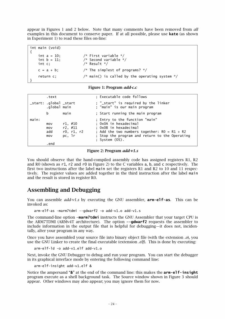
appear in Figures 1 and 2 below. Note that many comments have been removed from allexamples in this document to conserve paper. If at all possible, please use kate (as shownin Experiment 1) to read these files on-line:
int main (void){ int a = 10; /* First variable */ int b = 11; /* Second variable */ int c; /* Result */
c = a + b; /* The simplest of programs? */
return c; /* main() is called by the operating system */}
Figure 1: Program add-c.c
.text ; Executable code follows
_start: .global _start ; "_start" is required by the linker .global main ; "main" is our main program
b main ; Start running the main program
main: ; Entry to the function "main" mov r1, #10 ; 0x0A in hexadecimal mov r2, #11 ; 0x0B in hexadecimal add r0, r1, r2 ; Add the two numbers together: R0 = R1 + R2 mov pc, lr ; Stop the program and return to the Operating ; System (OS). .end
Figure 2: Program add-v1.s
You should observe that the hand-compiled assembly code has assigned registers R1, R2and R0 (shown as r1, r2 and r0 in Figure 2) to the C variables a, b, and c respectively. Thefirst two instructions after the label main set the registers R1 and R2 to 10 and 11 respec-tively. The register values are added together in the third instruction after the label mainand the result is stored in register R0.
Assembling and Debugging
You can assemble add-v1.s by executing the GNU assembler, arm-elf-as. This can beinvoked as:
arm-elf-as -marm7tdmi --gdwarf2 -o add-v1.o add-v1.s
The command-line option –marm7tdmi instructs the GNU Assembler that your target CPU isthe ARM7TDMI (ARMv4T architecture). The option ––gdwarf2 requests the assembler toinclude information in the output file that is helpful for debugging—it does not, inciden-tally, alter your program in any way.
Once you have assembled your source file into binary object file (with the extension .o), youuse the GNU Linker to create the final executable (extension .elf). This is done by executing:
arm-elf-ld -o add-v1.elf add-v1.o
Next, invoke the GNU Debugger to debug and run your program. You can start the debuggerin its graphical interface mode by entering the following command line:
arm-elf-insight add-v1.elf &
Notice the ampersand “&” at the end of the command line: this makes the arm-elf-insightprogram execute as a shell background task. The Source window shown in Figure 3 shouldappear. Other windows may also appear; you may ignore them for now.
– 25 –
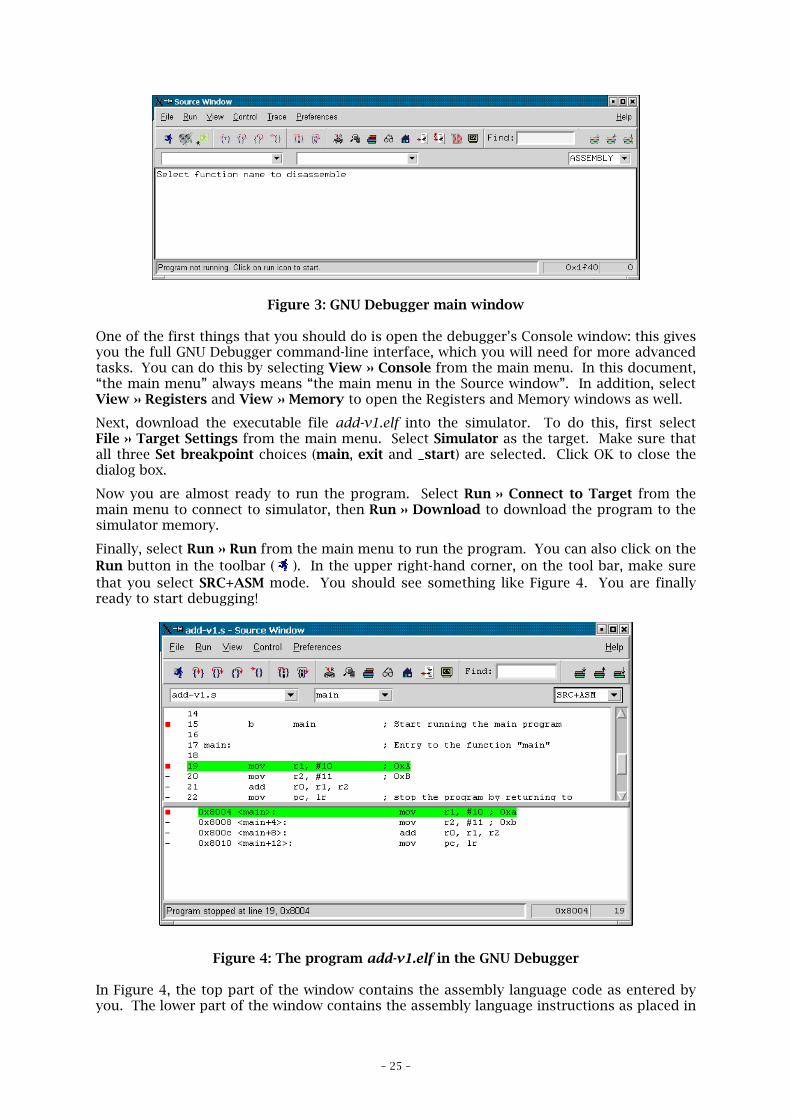
Figure 3: GNU Debugger main window
One of the first things that you should do is open the debugger’s Console window: this givesyou the full GNU Debugger command-line interface, which you will need for more advancedtasks. You can do this by selecting View » Console from the main menu. In this document,“the main menu” always means “the main menu in the Source window”. In addition, selectView » Registers and View » Memory to open the Registers and Memory windows as well.
Next, download the executable file add-v1.elf into the simulator. To do this, first selectFile » Target Settings from the main menu. Select Simulator as the target. Make sure thatall three Set breakpoint choices (main, exit and _start) are selected. Click OK to close thedialog box.
Now you are almost ready to run the program. Select Run » Connect to Target from themain menu to connect to simulator, then Run » Download to download the program to thesimulator memory.
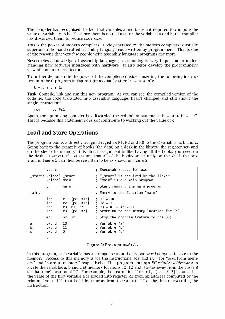
Finally, select Run » Run from the main menu to run the program. You can also click on theRun button in the toolbar ( ). In the upper right-hand corner, on the tool bar, make surethat you select SRC+ASM mode. You should see something like Figure 4. You are finallyready to start debugging!
Figure 4: The program add-v1.elf in the GNU Debugger
In Figure 4, the top part of the window contains the assembly language code as entered byyou. The lower part of the window contains the assembly language instructions as placed in

– 26 –
memory by the GNU Linker, arm-elf-ld. The linker uses 0x8000 as the starting addressfor the program. Each instruction occupies exactly 4 bytes in memory.
In the Registers window, inspect the value for register PC (shown as pc in the window).What is its value? Register PC points to the current instruction being executed; that is, itshows the address of the instruction being executed. In the Memory window, you can checkthe contents of memory at address 0x8000 (and following) by simply entering that addressin the Address edit box. The program instructions shown in the lower part of Source win-dow should then appear as hexadecimal numbers.
Step through the instructions by clicking on Step in the toolbar ( ). Check the contents ofregisters PC (shown as pc or r15), R1, R2 and R0 as you step through the instructions.
Note: As you try execute the last instruction, “mov pc, lr”, the simulator may gointo an infinite “busy doing nothing” loop. You can stop the program by clicking onthe Stop button in the toolbar ( ). Be warned that it may take the debugger a littlewhile to respond… You may see a dialog box with the message “Program receivedsignal SIGINT, Interrupt”. If so, click OK.
Compiling C Programs
Task: You can compile the add-c.c source file by executing the GNU compiler, arm-elf-gcc.This can be invoked as:
arm-elf-gcc -c -mcpu=arm7tdmi -O2 -g -Wall -o add-c.o add-c.c
By the way, be careful to note that the -O2 option in this command line uses the capitalletter “O”, not the number zero!
Use the GNU Linker to link add-c.o and the start-up routines in cstart.o to create the finalexecutable (extension .elf):
arm-elf-ld -o add-c.elf add-c.o cstart.o
Alternatively, you can use the make command to automatically generate the add-c.o and add-c.elf files. This command usually reads a file called Makefile to get its instructions (althoughyou can direct it to use any other file you like); this file essentially contains the equivalent ofcommand lines that you would otherwise type.
Note: The contents of make-files are a bit cryptic, to say the least! However, usingsuch files “as is” can save you a lot of typing. In the laboratory experiments for thiscourse, the make-files are named after the source code files, with a .make extension.So, for example, the make-file for add-c.elf is add-c.make. Type “make –fmakefile” to use a particular make-file makefile. Thus, to create add-c.elf, type:
make –f add-c.make
You can also delete add-c.o and add-c.elf (the compiler-generated files) by typing:
make –f add-c.make clean
If you don’t want to use make, you can write a simple shell script that contains all thecommands you need. You can then execute the shell script file at any time.
Now you can invoke the GNU Debugger to debug and run add-c.elf. Make sure that youselect SRC+ASM mode, then choose add-c.c from the list on the left-hand side, and mainfrom the list in the middle.
Compare the hand-assembled version of the program add-v1.s (in Figure 2) with the com-piler-generated version of the program add-c.s (Figure 1). Look at instructions around thelabel main in the compiled code. Three instructions in our hand-assembled code have beenreplaced with just one instruction:
mov r0, #21
– 27 –
The compiler has recognised the fact that variables a and b are not required to compute thevalue of variable c to be 21. Since there is no real use for the variables a and b, the compilerhas discarded them, to reduce code size.
This is the power of modern compilers! Code generated by the modern compilers is usuallysuperior to the hand-crafted assembly language code written by programmers. This is oneof the reasons that very few people write assembly language programs any more!
Nevertheless, knowledge of assembly language programming is very important in under-standing how software interfaces with hardware. It also helps develop the programmer’sview of computer architecture.
To further demonstrate the power of the compiler, consider inserting the following instruc-tion into the C program in Figure 1 (immediately after “c = a + b”):
b = a + b + 1;
Task: Compile, link and run this new program. As you can see, the compiled version of thecode (ie, the code translated into assembly language) hasn’t changed and still shows thesingle instruction:
mov r0, #21
Again, the optimising compiler has discarded the redundant statement “b = a + b + 1;”.This is because this statement does not contribute to working out the value of c.
Load and Store Operations
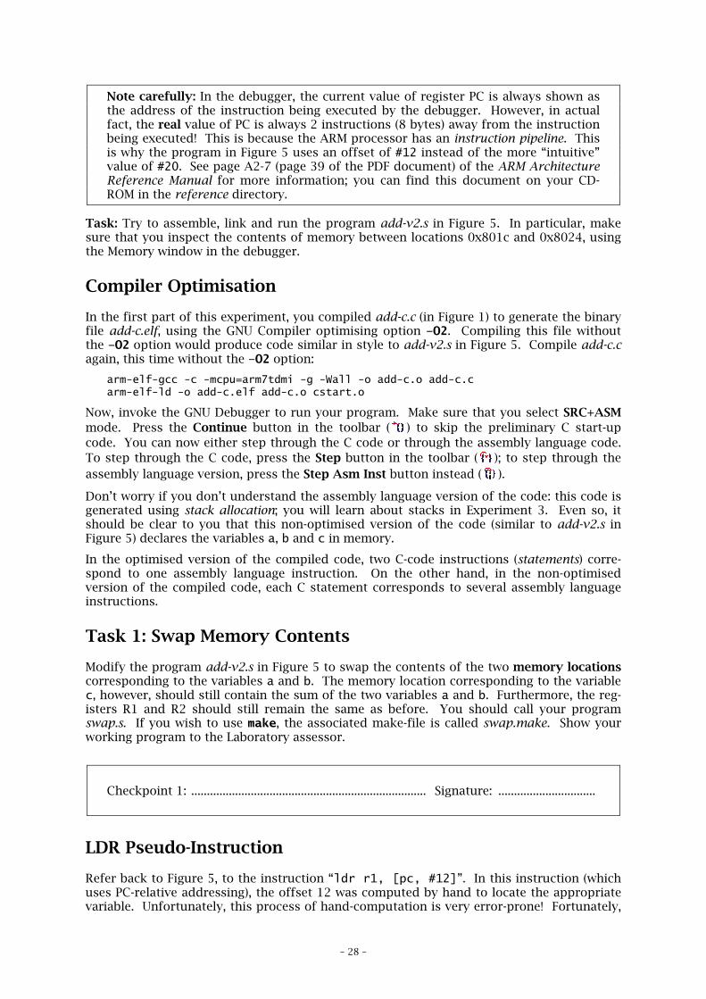
The program add-v1.s directly assigned registers R1, R2 and R0 to the C variables a, b and c.Going back to the example of books (the data) on a desk in the library (the register set) andon the shelf (the memory), this direct assignment is like having all the books you need onthe desk. However, if you assume that all of the books are initially on the shelf, the pro-gram in Figure 2 can then be rewritten to be as shown in Figure 5:
.text ; Executable code follows
_start: .global _start ; "_start" is required by the linker .global main ; "main" is our main program
b main ; Start running the main program
main: ; Entry to the function "main"
ldr r1, [pc, #12] ; R1 = 10 ldr r2, [pc, #12] ; R2 = 11 add r0, r1, r2 ; R0 = R1 + R2 = 21 str r0, [pc, #8] ; Store R0 to the memory location for "c"
mov pc, lr ; Stop the program (return to the OS)
a: .word 10 ; Variable "a"b: .word 11 ; Variable "b"c: .word 0 ; Variable "c"
.end
Figure 5: Program add-v2.s
In this program, each variable has a storage location that is one word (4 bytes) in size in thememory. Access to this memory is via the instructions ldr and str, for “load from mem-ory” and “store to memory” respectively. This program employs PC-relative addressing tolocate the variables a, b and c at memory locations 12, 12 and 8 bytes away from the current(at that time) location of PC. For example, the instruction “ldr r1, [pc, #12]” states thatthe value of the first variable a is loaded into register R1 from an address computed by therelation “pc + 12”, that is, 12 bytes away from the value of PC at the time of executing theinstruction.
– 28 –
Note carefully: In the debugger, the current value of register PC is always shown asthe address of the instruction being executed by the debugger. However, in actualfact, the real value of PC is always 2 instructions (8 bytes) away from the instructionbeing executed! This is because the ARM processor has an instruction pipeline. Thisis why the program in Figure 5 uses an offset of #12 instead of the more “intuitive”value of #20. See page A2-7 (page 39 of the PDF document) of the ARM ArchitectureReference Manual for more information; you can find this document on your CD-ROM in the reference directory.
Task: Try to assemble, link and run the program add-v2.s in Figure 5. In particular, makesure that you inspect the contents of memory between locations 0x801c and 0x8024, usingthe Memory window in the debugger.
Compiler Optimisation
In the first part of this experiment, you compiled add-c.c (in Figure 1) to generate the binaryfile add-c.elf, using the GNU Compiler optimising option –O2. Compiling this file withoutthe –O2 option would produce code similar in style to add-v2.s in Figure 5. Compile add-c.cagain, this time without the –O2 option:
arm-elf-gcc -c -mcpu=arm7tdmi -g -Wall -o add-c.o add-c.carm-elf-ld -o add-c.elf add-c.o cstart.o
Now, invoke the GNU Debugger to run your program. Make sure that you select SRC+ASMmode. Press the Continue button in the toolbar ( ) to skip the preliminary C start-upcode. You can now either step through the C code or through the assembly language code.To step through the C code, press the Step button in the toolbar ( ); to step through theassembly language version, press the Step Asm Inst button instead ( ).
Don’t worry if you don’t understand the assembly language version of the code: this code isgenerated using stack allocation; you will learn about stacks in Experiment 3. Even so, itshould be clear to you that this non-optimised version of the code (similar to add-v2.s inFigure 5) declares the variables a, b and c in memory.
In the optimised version of the compiled code, two C-code instructions (statements) corre-spond to one assembly language instruction. On the other hand, in the non-optimisedversion of the compiled code, each C statement corresponds to several assembly languageinstructions.
Task 1: Swap Memory Contents
Modify the program add-v2.s in Figure 5 to swap the contents of the two memory locationscorresponding to the variables a and b. The memory location corresponding to the variablec, however, should still contain the sum of the two variables a and b. Furthermore, the reg-isters R1 and R2 should still remain the same as before. You should call your programswap.s. If you wish to use make, the associated make-file is called swap.make. Show yourworking program to the Laboratory assessor.
Checkpoint 1: ........................................................................... Signature: ...............................
LDR Pseudo-Instruction
Refer back to Figure 5, to the instruction “ldr r1, [pc, #12]”. In this instruction (whichuses PC-relative addressing), the offset 12 was computed by hand to locate the appropriatevariable. Unfortunately, this process of hand-computation is very error-prone! Fortunately,
– 29 –
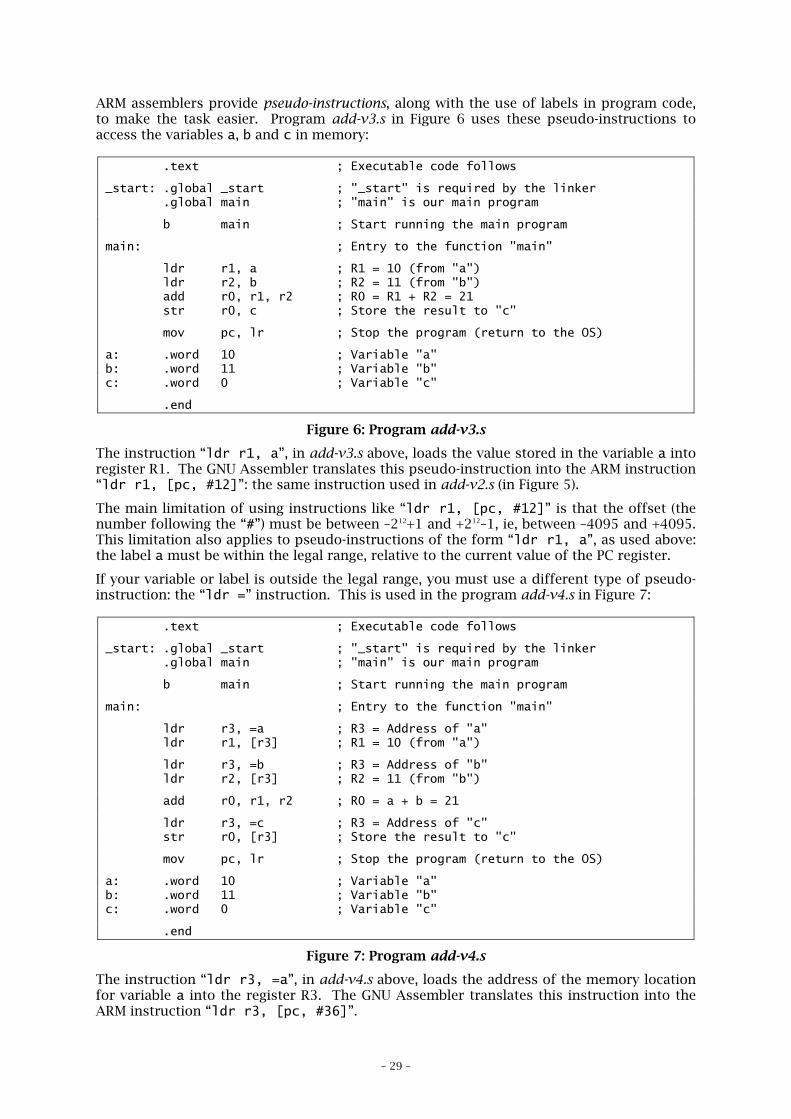
ARM assemblers provide pseudo-instructions, along with the use of labels in program code,to make the task easier. Program add-v3.s in Figure 6 uses these pseudo-instructions toaccess the variables a, b and c in memory:
.text ; Executable code follows
_start: .global _start ; "_start" is required by the linker .global main ; "main" is our main program
b main ; Start running the main program
main: ; Entry to the function "main"
ldr r1, a ; R1 = 10 (from "a") ldr r2, b ; R2 = 11 (from "b") add r0, r1, r2 ; R0 = R1 + R2 = 21 str r0, c ; Store the result to "c"
mov pc, lr ; Stop the program (return to the OS)
a: .word 10 ; Variable "a"b: .word 11 ; Variable "b"c: .word 0 ; Variable "c"
.end
Figure 6: Program add-v3.s
The instruction “ldr r1, a”, in add-v3.s above, loads the value stored in the variable a intoregister R1. The GNU Assembler translates this pseudo-instruction into the ARM instruction“ldr r1, [pc, #12]”: the same instruction used in add-v2.s (in Figure 5).
The main limitation of using instructions like “ldr r1, [pc, #12]” is that the offset (thenumber following the “#”) must be between –212+1 and +212–1, ie, between –4095 and +4095.This limitation also applies to pseudo-instructions of the form “ldr r1, a”, as used above:the label a must be within the legal range, relative to the current value of the PC register.
If your variable or label is outside the legal range, you must use a different type of pseudo-instruction: the “ldr =” instruction. This is used in the program add-v4.s in Figure 7:
.text ; Executable code follows
_start: .global _start ; "_start" is required by the linker .global main ; "main" is our main program
b main ; Start running the main program
main: ; Entry to the function "main"
ldr r3, =a ; R3 = Address of "a" ldr r1, [r3] ; R1 = 10 (from "a")
ldr r3, =b ; R3 = Address of "b" ldr r2, [r3] ; R2 = 11 (from "b")
add r0, r1, r2 ; R0 = a + b = 21
ldr r3, =c ; R3 = Address of "c" str r0, [r3] ; Store the result to "c"
mov pc, lr ; Stop the program (return to the OS)
a: .word 10 ; Variable "a"b: .word 11 ; Variable "b"c: .word 0 ; Variable "c"
.end
Figure 7: Program add-v4.s
The instruction “ldr r3, =a”, in add-v4.s above, loads the address of the memory locationfor variable a into the register R3. The GNU Assembler translates this instruction into theARM instruction “ldr r3, [pc, #36]”.
– 30 –
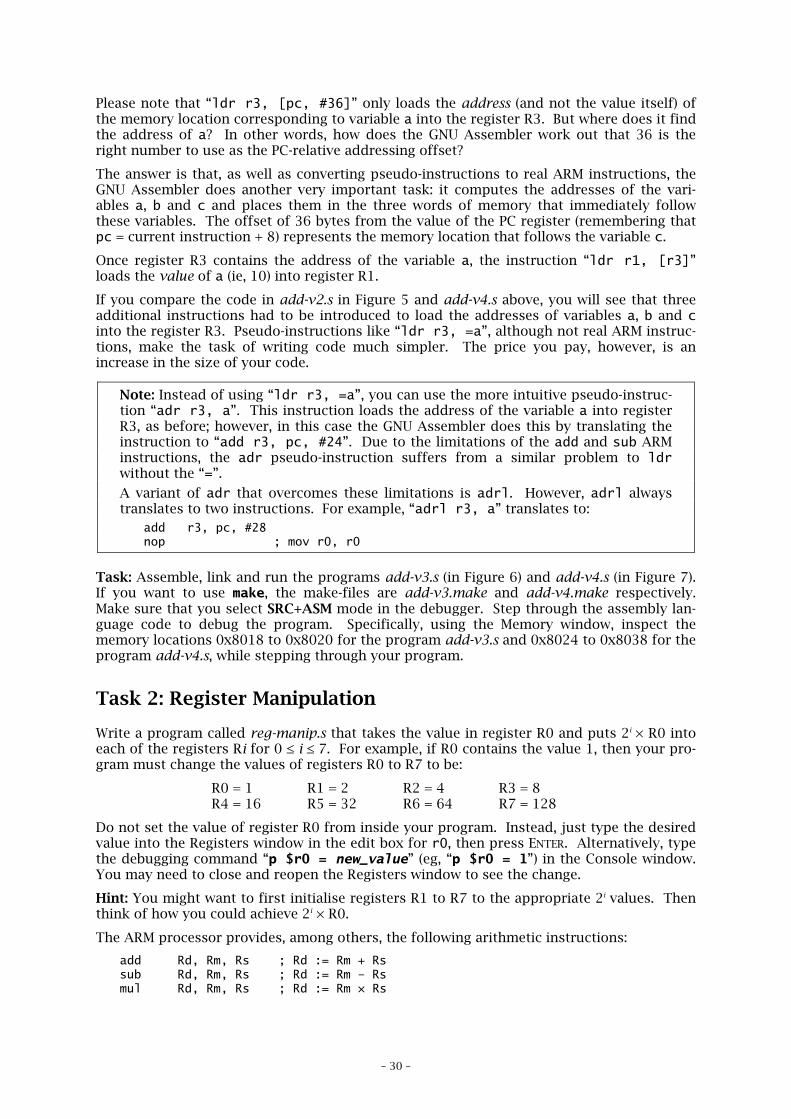
Please note that “ldr r3, [pc, #36]” only loads the address (and not the value itself) ofthe memory location corresponding to variable a into the register R3. But where does it findthe address of a? In other words, how does the GNU Assembler work out that 36 is theright number to use as the PC-relative addressing offset?
The answer is that, as well as converting pseudo-instructions to real ARM instructions, theGNU Assembler does another very important task: it computes the addresses of the vari-ables a, b and c and places them in the three words of memory that immediately followthese variables. The offset of 36 bytes from the value of the PC register (remembering thatpc = current instruction + 8) represents the memory location that follows the variable c.
Once register R3 contains the address of the variable a, the instruction “ldr r1, [r3]”loads the value of a (ie, 10) into register R1.
If you compare the code in add-v2.s in Figure 5 and add-v4.s above, you will see that threeadditional instructions had to be introduced to load the addresses of variables a, b and cinto the register R3. Pseudo-instructions like “ldr r3, =a”, although not real ARM instruc-tions, make the task of writing code much simpler. The price you pay, however, is anincrease in the size of your code.
Note: Instead of using “ldr r3, =a”, you can use the more intuitive pseudo-instruc-tion “adr r3, a”. This instruction loads the address of the variable a into registerR3, as before; however, in this case the GNU Assembler does this by translating theinstruction to “add r3, pc, #24”. Due to the limitations of the add and sub ARMinstructions, the adr pseudo-instruction suffers from a similar problem to ldrwithout the “=”.
A variant of adr that overcomes these limitations is adrl. However, adrl alwaystranslates to two instructions. For example, “adrl r3, a” translates to:
add r3, pc, #28nop ; mov r0, r0
Task: Assemble, link and run the programs add-v3.s (in Figure 6) and add-v4.s (in Figure 7).If you want to use make, the make-files are add-v3.make and add-v4.make respectively.Make sure that you select SRC+ASM mode in the debugger. Step through the assembly lan-guage code to debug the program. Specifically, using the Memory window, inspect thememory locations 0x8018 to 0x8020 for the program add-v3.s and 0x8024 to 0x8038 for theprogram add-v4.s, while stepping through your program.
Task 2: Register Manipulation
Write a program called reg-manip.s that takes the value in register R0 and puts 2i × R0 intoeach of the registers Ri for 0 ≤ i ≤ 7. For example, if R0 contains the value 1, then your pro-gram must change the values of registers R0 to R7 to be:
R0 = 1 R1 = 2 R2 = 4 R3 = 8R4 = 16 R5 = 32 R6 = 64 R7 = 128
Do not set the value of register R0 from inside your program. Instead, just type the desiredvalue into the Registers window in the edit box for r0, then press ENTER. Alternatively, typethe debugging command “p $r0 = new_value” (eg, “p $r0 = 1”) in the Console window.You may need to close and reopen the Registers window to see the change.
Hint: You might want to first initialise registers R1 to R7 to the appropriate 2i values. Thenthink of how you could achieve 2i × R0.
The ARM processor provides, among others, the following arithmetic instructions:
add Rd, Rm, Rs ; Rd := Rm + Rssub Rd, Rm, Rs ; Rd := Rm – Rsmul Rd, Rm, Rs ; Rd := Rm × Rs
– 31 –
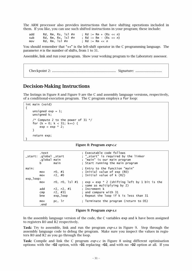
The ARM processor also provides instructions that have shifting operations included inthem. If you like, you can use such shifted instructions in your program; these include:
add Rd, Rm, Rs, lsl #n ; Rd := Rm + (Rs << n)sub Rd, Rm, Rs, lsl #n ; Rd := Rm – (Rs << n)mov Rd, Rm, lsl #n ; Rd := Rm << n
You should remember that “<<” is the left-shift operator in the C programming language. Theparameter n is the number of shifts, from 1 to 31.
Assemble, link and run your program. Show your working program to the Laboratory assessor.
Checkpoint 2: ........................................................................... Signature: ...............................
Decision-Making Instructions
The listings in Figure 8 and Figure 9 are the C and assembly language versions, respectively,of a conditional-execution program. The C program employs a for loop:
int main (void){ unsigned exp = 1; unsigned k;
/* Compute 2 to the power of 31 */ for (k = 0; k < 31; k++) { exp = exp * 2; }
return exp;}
Figure 8: Program exp-c.c
.text ; Executable code follows_start: .global _start ; "_start" is required by the linker .global main ; "main" is our main program b main ; Start running the main program
main: ; Entry to the function "main" mov r0, #1 ; Initial value of exp (R0) mov r2, #0 ; Initial value of k (R2)exp_loop: mov r0, r0, lsl #1 ; exp = exp * 2 (shifting left by 1 bit is the ; same as multiplying by 2) add r2, r2, #1 ; Increment k cmp r2, #31 ; and compare with 31 bne exp_loop ; Repeat the loop if k is less than 31
mov pc, lr ; Terminate the program (return to OS) .end
Figure 9: Program exp-s.s
In the assembly language version of the code, the C variables exp and k have been assignedto registers R0 and R2 respectively.
Task: Try to assemble, link and run the program exp-s.s in Figure 9. Step through theassembly language code to debug the program. Make sure you inspect the values in regis-ters R0 and R2 as you go through the loop.
Task: Compile and link the C program exp-c.c in Figure 8 using different optimisationoptions: with the -O2 option, with -O1 replacing -O2, and with no -O2 option at all. If you
– 32 –
type “make –f exp-c.make”, all three versions will be generated for you (and called exp-c-withO2.elf, exp-c-withO1.elf and exp-c-noopt.elf respectively). Look at these files using thedebugger; make sure that you select SRC+ASM mode. Step through the generated assemblylanguage code as you run the program. How does the compiled code compare to the hand-coded assembly language version in Figure 9?
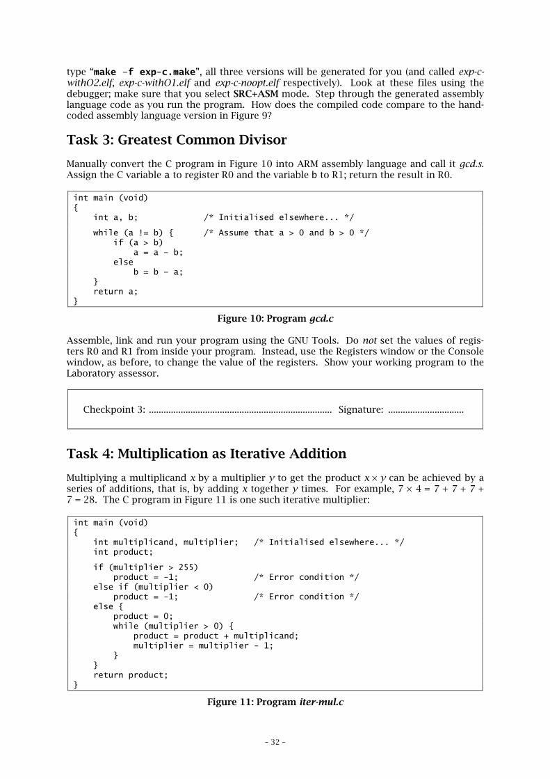
Task 3: Greatest Common Divisor
Manually convert the C program in Figure 10 into ARM assembly language and call it gcd.s.Assign the C variable a to register R0 and the variable b to R1; return the result in R0.
int main (void){ int a, b; /* Initialised elsewhere... */
while (a != b) { /* Assume that a > 0 and b > 0 */ if (a > b) a = a – b; else b = b – a; } return a;}
Figure 10: Program gcd.c
Assemble, link and run your program using the GNU Tools. Do not set the values of regis-ters R0 and R1 from inside your program. Instead, use the Registers window or the Consolewindow, as before, to change the value of the registers. Show your working program to theLaboratory assessor.
Checkpoint 3: ........................................................................... Signature: ...............................
Task 4: Multiplication as Iterative Addition
Multiplying a multiplicand x by a multiplier y to get the product x × y can be achieved by aseries of additions, that is, by adding x together y times. For example, 7 × 4 = 7 + 7 + 7 +7 = 28. The C program in Figure 11 is one such iterative multiplier:
int main (void){ int multiplicand, multiplier; /* Initialised elsewhere... */ int product;
if (multiplier > 255) product = -1; /* Error condition */ else if (multiplier < 0) product = -1; /* Error condition */ else { product = 0; while (multiplier > 0) { product = product + multiplicand; multiplier = multiplier - 1; } } return product;}
Figure 11: Program iter-mul.c
– 33 –
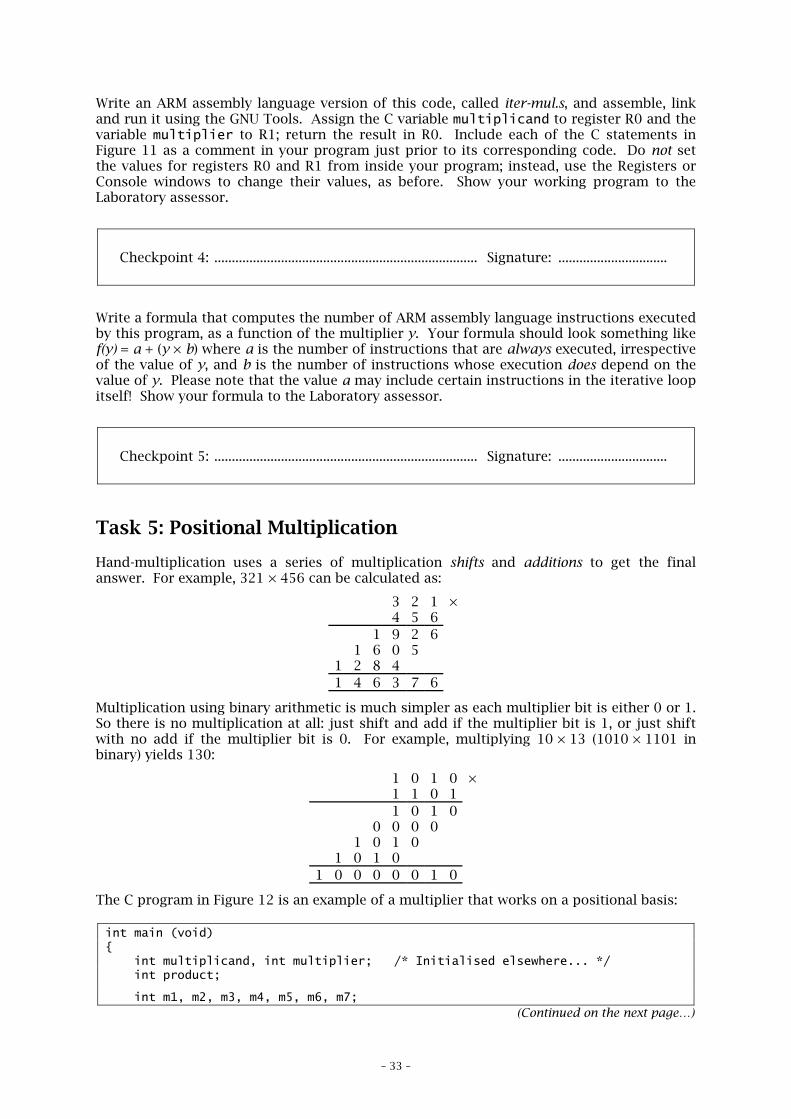
Write an ARM assembly language version of this code, called iter-mul.s, and assemble, linkand run it using the GNU Tools. Assign the C variable multiplicand to register R0 and thevariable multiplier to R1; return the result in R0. Include each of the C statements inFigure 11 as a comment in your program just prior to its corresponding code. Do not setthe values for registers R0 and R1 from inside your program; instead, use the Registers orConsole windows to change their values, as before. Show your working program to theLaboratory assessor.
Checkpoint 4: ........................................................................... Signature: ...............................
Write a formula that computes the number of ARM assembly language instructions executedby this program, as a function of the multiplier y. Your formula should look something likef(y) = a + (y × b) where a is the number of instructions that are always executed, irrespectiveof the value of y, and b is the number of instructions whose execution does depend on thevalue of y. Please note that the value a may include certain instructions in the iterative loopitself! Show your formula to the Laboratory assessor.
Checkpoint 5: ........................................................................... Signature: ...............................
Task 5: Positional Multiplication
Hand-multiplication uses a series of multiplication shifts and additions to get the finalanswer. For example, 321 × 456 can be calculated as:
3 2 1 ×4 5 6
1 9 2 61 6 0 5
1 2 8 41 4 6 3 7 6
Multiplication using binary arithmetic is much simpler as each multiplier bit is either 0 or 1.So there is no multiplication at all: just shift and add if the multiplier bit is 1, or just shiftwith no add if the multiplier bit is 0. For example, multiplying 10 × 13 (1010 × 1101 inbinary) yields 130:
1 0 1 0 ×1 1 0 11 0 1 0
0 0 0 01 0 1 0
1 0 1 01 0 0 0 0 0 1 0
The C program in Figure 12 is an example of a multiplier that works on a positional basis:
int main (void){ int multiplicand, int multiplier; /* Initialised elsewhere... */ int product;
int m1, m2, m3, m4, m5, m6, m7;(Continued on the next page…)
– 34 –
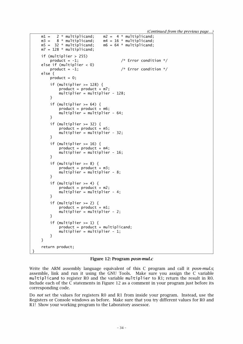
(Continued from the previous page…) m1 = 2 * multiplicand; m2 = 4 * multiplicand; m3 = 8 * multiplicand; m4 = 16 * multiplicand; m5 = 32 * multiplicand; m6 = 64 * multiplicand; m7 = 128 * multiplicand;
if (multiplier > 255) product = -1; /* Error condition */ else if (multiplier < 0) product = -1; /* Error condition */ else { product = 0;
if (multiplier >= 128) { product = product + m7; multiplier = multiplier - 128; }
if (multiplier >= 64) { product = product + m6; multiplier = multiplier - 64; }
if (multiplier >= 32) { product = product + m5; multiplier = multiplier - 32; }
if (multiplier >= 16) { product = product + m4; multiplier = multiplier - 16; }
if (multiplier >= 8) { product = product + m3; multiplier = multiplier - 8; }
if (multiplier >= 4) { product = product + m2; multiplier = multiplier - 4; }
if (multiplier >= 2) { product = product + m1; multiplier = multiplier - 2; }
if (multiplier >= 1) { product = product + multiplicand; multiplier = multiplier - 1; } }
return product;}
Figure 12: Program posn-mul.c
Write the ARM assembly language equivalent of this C program and call it posn-mul.s;assemble, link and run it using the GNU Tools. Make sure you assign the C variablemultiplicand to register R0 and the variable multiplier to R1; return the result in R0.Include each of the C statements in Figure 12 as a comment in your program just before itscorresponding code.
Do not set the values for registers R0 and R1 from inside your program. Instead, use theRegisters or Console windows as before. Make sure that you try different values for R0 andR1! Show your working program to the Laboratory assessor.
– 35 –
Checkpoint 6: ........................................................................... Signature: ...............................
Write a formula that computes the number of ARM assembly language instructions executedby this program. You may assume that 50% of the if-statements are true. Show your for-mula to the Laboratory assessor. Please note that your “formula” may just be a simple inte-ger number, depending on how you wrote your program for Checkpoint 6.
How many instructions do each of these approaches to multiplication (iterative vs. posi-tional) execute to multiply a number by 0? By 255? What conclusion can you draw fromthese results regarding the two algorithms?
Checkpoint 7: ........................................................................... Signature: ...............................