Novel robot arm design and implementation for hot forging ...
16
Full Terms & Conditions of access and use can be found at http://www.tandfonline.com/action/journalInformation?journalCode=tprs20 International Journal of Production Research ISSN: 0020-7543 (Print) 1366-588X (Online) Journal homepage: http://www.tandfonline.com/loi/tprs20 Novel robot arm design and implementation for hot forging press automation Chu A. My, Chi Hieu Le, Michael Packianather & Erik L.J. Bohez To cite this article: Chu A. My, Chi Hieu Le, Michael Packianather & Erik L.J. Bohez (2018): Novel robot arm design and implementation for hot forging press automation, International Journal of Production Research, DOI: 10.1080/00207543.2018.1521026 To link to this article: https://doi.org/10.1080/00207543.2018.1521026 Published online: 14 Sep 2018. Submit your article to this journal Article views: 8 View Crossmark data
-
Upload
khangminh22 -
Category
Documents
-
view
3 -
download
0
Transcript of Novel robot arm design and implementation for hot forging ...
Full Terms & Conditions of access and use can be found athttp://www.tandfonline.com/action/journalInformation?journalCode=tprs20
International Journal of Production Research
ISSN: 0020-7543 (Print) 1366-588X (Online) Journal homepage: http://www.tandfonline.com/loi/tprs20
Novel robot arm design and implementation forhot forging press automation
Chu A. My, Chi Hieu Le, Michael Packianather & Erik L.J. Bohez
To cite this article: Chu A. My, Chi Hieu Le, Michael Packianather & Erik L.J. Bohez (2018): Novelrobot arm design and implementation for hot forging press automation, International Journal ofProduction Research, DOI: 10.1080/00207543.2018.1521026
To link to this article: https://doi.org/10.1080/00207543.2018.1521026
Published online: 14 Sep 2018.
Submit your article to this journal
Article views: 8
View Crossmark data

International Journal of Production Research, 2018https://doi.org/10.1080/00207543.2018.1521026
Novel robot arm design and implementation for hot forging press automation
Chu A. Mya∗, Chi Hieu Leb, Michael Packianatherc and Erik L.J. Bohezd
aDepartment of Special Robotics and Mechatronics, Le Quy Don Technical University, Hanoi, Vietnam; bFaculty of Engineering andScience, University of Greenwich, Kent, UK; cSchool of Engineering, Cardiff University, Cardiff, UK; dSchool of Advanced
Technologies, Asian Institute of Technology, Bangkok, Thailand
(Received 20 May 2018; accepted 13 August 2018)
Manual handling of hot and heavy workpiece in forging press industry increases the process time and causes safety risksto workers. To increase the productivity and optimise the use of manpower, manipulators are needed to be designed forsupporting the workers handling the workpiece. Designing robots for such applications is challenging since the robot suffersfrom a heavy payload at the arm tip, and it operates at a high speed in a large workspace. This research addresses the designand implementation of a novel robot for handling workpiece for a given forging press cell. A novel robotic mechanism isdesigned with two key features: (i) the addition of parallel links in between serial links and (ii) the use of hydraulic actuatorsfor driving robot’s joints. The addition of parallel links and the use of hydraulic cylinders are to increase the structuralrigidity. It is also to reduce the number of joint variables and restrict the end-effector moving parallel to the ground surfaceso that the robot grips and releases the workpiece in a more efficient and simplified manner. The effectiveness of the designedrobot mechanism is demonstrated through functional tests, and experimental results are carried out on the implemented robot.
Keywords: Design of production systems; robotic cells; productivity improvement; robot systems; robot applications; robotgrippers; material handling; forging press; serial–parallel robot
1. Introduction
Hydraulic hot forging press is the process of shaping a hot workpiece that is placed in a die by applying hydraulic pressure.This type of forging is usually done in a forging press machine that applies gradual pressure on the forging die. A manu-facturing cell of hot forging press usually consists of two main components: a heating furnace and a forging press machine.The hot forging press process includes two main steps: the workpiece heating and the workpiece forging.
In practice, one of the most important aspects of the manufacturing process is related to the material transfer whichsignificantly impacts on the productivity and the safety issue for workers.
As stated by Gougar, Cho, and Prabhu (2002), efficient and timely material transfer is becoming critical in manufacturingsystems. The speed with which a workpiece in the process is transferred has a direct and obvious impact on the quality of theproduct and the throughput of the manufacturing system. Furthermore, factory management, organisation and schedulingdecisions are significantly influenced by the efficiency of the material transfer system, which in turn affects the productivityand competitiveness of the manufacturing system as a whole (Gultekin, Akturk, and Karasan 2008; Yildiz, Akturk, andKarasan 2011; Boudella, Sahin, and Dallery 2018, Sriskandarajah and Shetty 2018). Though the efficiency of manufacturingsystems is much affected by the material transfer, manual methods of material handling have been widely used in forgingindustry. The use of manual methods increases the downtimes and causes safety and health risks and environmental hazardsto workers since the workers grasp and move directly the working piece with tongs. As for costs of using robots in industries,Tilley (2017) reported that as robot production has increased, costs have gone down. Over the past 30 years, the averagerobot price has fallen by half in real terms and even further relative to labour costs. These critical issues have motivated andencouraged the implementation of innovative robot design for the material handling. However, designing a robot arm for thementioned application usually copes with challenges since the robot usually suffers from a heavy payload at the arm tip, andit must operate at high speed in a large operational space. As for the given forging press workshop under consideration inthis research, the designed robot is required to handle workpiece weighted about 60 kg. It must transfer a heated workpiecealong a distance of 2.5 m, the distance between the heating furnace and the press machine, within a limited time period of20 s. This is a critical task for the design of the robot.
*Corresponding author. Email: [email protected]
© 2018 Informa UK Limited, trading as Taylor & Francis Group

2 C. A. My et al.
Notice that, in the robot market, there have been some kinds of high payload industrial robots such as products of KukaHigh Payload Robot Series or Fanuc M-2000 Series that can be selected for the application. However, if such a robot isselected for the application, the griper of the robot could be redesigned, other components related to the griper could berevised, fixtures could be added, and much work on experimental integration and testing must be carried out. Hence, theintegration of the robot for the application could be not economical and inefficient.
This paper presents the design and implementation of a novel robot arm capable of replacing workers to grasp andtransfer workpiece among the components of a given forging press manufacturing system. For the arm design, a novelrobotic mechanism is designed with two special features: (i) two successive parallel links are added in between serial linksand (ii) hydraulic cylinders are selected for driving active joints of the robot. The addition of parallel links and the use ofhydraulic cylinders as auxiliary links appended to the robot architecture are necessary to increase the structural rigidity of thearm. Besides, the combination of the parallel–serial links reduces the DOFs of the mechanism and restricts the end-effectormoving parallel to the ground surface as desired. The reduction of the DOFs leads to reduce the number of actuators derivingthe robot so that it simplifies the control system. Since the orientation of the end-effector is optimised, the robot grips andreleases the workpiece in an efficient and simple manner. It also improves the positioning accuracy and repeatability of thegripper. Additionally, the workpiece is always oriented in either vertical direction or horizontal plane only so that it increasesthe stability and stiffness of the arm while moving a heated workpiece at high speed.
The design of the arm is then validated via kinematic performance analysis, quasi-static modelling and analysis, andstructural performance simulation. Note that the kinematic modelling of the designed robot is more complicated than that ofthe conventional serial arm, because of the hybrid serial–parallel feature of the robot architecture. The kinematical constraintequation must be formulated and put together with the kinematic model. Based on the entire kinematic model formulated,the inverse kinematics and the transferring time are analysed and discussed to demonstrate the kinematical performance.In addition, to investigate the structural characteristics of the end-effector module, the static displacement and the stressdistributed on module’s components are computed and simulated by using the computer-aided finite element method (FEM).Besides, to analyse the applied torques imposing on the robot system, the quasi-static model is formulated as well. Thusthe loading capability of the selected hydraulic cylinders can be assessed and discussed. Finally, the effectiveness of thedesigned system is demonstrated through functional tests and experiments. The testing results demonstrate the workingperformance of the designed system. By applying the robotised solution, the average cycle time of the production is reducedby 27.7% approximately.
It is noticeable that the hot forging press process under consideration is different from the open die forging processmentioned in researches by Yan, Gao, and Zhang (2010), Chen et al. (2012), Faguo et al. (2008) and Ding et al. (2017).The manipulators designed for the open die forging is to hold and manipulate a workpiece for the forging process, whereasthe robot arm presented in this work is designed to pickup, transfer and release workpiece among given positions in a largeworkspace of a hot forging press cell.
2. Related work
The use of robots for industrial applications is a practice, which has started years ago. Early designs of robotic systemsconcentrating on industrial manipulators are mostly to perform tasks such as welding, painting and palletising (Garcia et al.2007). The state of the art in robotics can be found out in the report by Forge and Blackman (2010). In the literature, thereare two main categories of researches focusing on the design and integration of robotic systems for manufacturing cells. Thefirst category concentrates on the use of general purpose robots (commercial robots), and the second one aims at designingand implementation of robotic systems.
In the first approach, commercial robots are selected and used to perform the required tasks. Related to this issue,Olsson et al. (2010) use a light-weight industrial robot for a high-precision drilling system, based on the technique of high-performance force/torque control. Denkena and Lepper (2015) investigate a cost-effective manufacturing of large frameparts for the aerospace industry with an industrial robot of low stiffness of the robot structure. Huang and Lin (2002)develop a robotic cell, in which two industrial robots are used for manufacturing complex objects. The system is shown tobe flexible, reconfigurable, automatic and capable of manufacturing complex prototypes in the current industry environment.
The optimal selection of robots for robotic cells is investigated by several authors as well. Karsak (2008) introducesa decision model based on quality function deployment and fuzzy linear regression. Kentli and Kar (2011) propose amulti-criteria model using satisfaction function to convert various robot attributes into a unified scale. A distance mea-sure technique is also used to ascertain the highest ranked candidate-robot. Liu et al. (2014) handle the robot selection issuewith respect to uncertainties and incomplete information. This method considers both subjective judgements and objec-tive information in real-life applications, and models the uncertainty and diversity of decision-makers’ assessments usinginterval 2-tuple linguistic variables.
International Journal of Production Research 3
As for the robot–human collaboration, Michalos et al. (2014) propose a hybrid solution that involves the safe cooperationof operators with an adapting robotic system for an industrial assembly process. The focus is given to combining robotstrength, velocity, predictability, repeatability and precision with human intelligence and skills. Michalos et al. (2010) showthat the costs associated with delivering raw materials, moving work in process and removing finished goods, need to beminimised. At present, the automotive industry and its supply chains are main users of robotic systems, due to their abilityto accomplish tasks (assembly, inspection, etc.) of improved quality and repeatability. In the research by Cherubini et al.(2016), a collaborative human–robot mechanism for an assembly cell is considered where the robot alternates active andpassive behaviours during assembly. Thus the human workload is reduced, diminishing the risk of strain injuries.
The optimal use of industrial robots is significantly influenced by algorithms for tool path generation and solutions forthe task planning and sequencing. Dolgui and Pashkevich (2009) address a technique to optimise the tool path generationfor laser cutting robotic systems. The proposed optimisation emphasises on a six-axis robot motion for continuous contourtracking while considering the redundancy caused by the tool axial symmetry. In the research by Dolgui and Pashkevich(2006), an effective method for welding operations planning is presented for a robotic cell with a positioning table. Besides,to increase the productivity of robotic cells, there is a number of reported researches, which mostly deal with the sequencingand scheduling issue. Galante and Passannanti (2006) present the dimensioning and the scheduling of a material handlingsystem, constituted by more than one dual-gripper robot tending a manufacturing serial system. Gultekin, Akturk, andKarasan (2008) solve the robotic cell scheduling problem with M-machines under the assumption of the process and oper-ational flexibility. Yildiz, Akturk, and Karasan (2011) deal with the scheduling issue arising in an M-machine robotic cellconsisting of CNC machines to minimise the cycle time and the manufacturing cost simultaneously. Foumani, Gunawan,and Ibrahim (2014) study the scheduling of a rotationally arranged robotic cell with the multi-function robot. This is to min-imise the steady-state cycle time for identical part production. Kovács (2016) investigates the integrated task sequencingand path planning in a robotic cell of laser welding to find the appropriate order of welding tasks. Yang, Chen, and Long(2016) provide with a solution to the scheduling problem for a robotic manufacturing cell with multiple robots. Kim, Kim,and Lee (2017) present a scheduling strategy that controls robot task timings. It is to optimise the scheduling for sequentiallyconnected cluster tools with dual-armed robots with a single input and output module, which includes multi-cluster toolsand linear cluster tools. He, Stecke, and Smith (2016) investigate the part input sequencing and scheduling in flexible man-ufacturing systems in a mass customisation/mass personalisation environment. Both robot and machine scheduling rulesusing a state-dependent part input sequencing algorithm are taken into account. Thomasson et al. (2018) introduce the twinrobot palletising problem in which two robots must be scheduled and routed to pick up and deliver products at specifiedlocations along a rail. Sriskandarajah and Shetty (2018) examine the recent theoretical developments on the analysis ofthroughput optimisation in robotic cells served by a dual-gripper robot. The research focuses on the scheduling operationsin dual-gripper robotic cells that produce identical parts. The objective of the work is to find a cyclic sequence of robotmoves that minimises the long-run average time to produce a part or, equivalently, maximises the throughput. Boudella,Sahin, and Dallery (2018) optimise the assignment of stock keeping units for a hybrid kitting system that consists of arobot and an operator working in series to deliver parts to an assembly line so that the cycle time of the overall system isoptimised.
In the second approach, noticeable attempts have been made to design and implement new robots for a wide spectrum ofapplications. Gougar, Cho, and Prabhu (2002) present a method to design a high-speed robot with cycle times comparablewith the existed material transfer system using linear induction motors. A generic design methodology is developed forrobot manipulators that integrate several key design issues such as kinematics, dynamics, structural mechanics, actuatorsizing, assessing robustness to parameters and sensor errors, and vibration analysis. Tor et al. (2008) introduce an expertfunctional design model based on the designers’ behaviour-driven, function–environment–structure formalism, which istailored to meet the special requirements of industrial robot design. Years ago, particular robots have been increasinglydesigned and implemented: the high-speed manipulator for laser cutting applications (Youcef-Toumi and Kuo 1989), thehigh-performance loading robot for a tool-delivery system (Gougar, Cho, and Prabhu 2002), the hybrid mobile robots(Fiorini and Botturi 2008), the leg-wheel robot (Wei et al. 2017), the easy-to-use modular assistive robotic system (Kimet al. 2014), etc.
Parallel robots and serial–parallel robots have been investigated in the literature also. Pa and Wu (2012) and Jin, Chen,and Yang (2009) introduce the designs of a parallel robot for the open die forging. There has been a number of researchesfocusing on the forging manipulator – a kind of hybrid serial–parallel robots, of which issues related to the modelling andanalysis are discussed by Yan, Gao, and Zhang (2010) and Chen et al. (2012), and the synthesis of mechanism is consideredby Faguo et al. (2008) and Ding et al. (2017). Considering the hybrid serial–parallel structure, Pinskier et al. (2018) addressa master–slave manipulator consisting of a 4-DOF hybrid parallel–serial slave mechanism. Carbone and Ceccarelli (2005)present a serial–parallel manipulator by investigating the feasibility of combining two different robotic structures into onerobot.

4 C. A. My et al.
Note that, though a diversity of general purpose robots has been used for manufacturing systems, and much researchrelated to the optimisation of robotic cell performance has been carried out, which demonstrates advantages of the useof general purpose robots, commercial industrial robots are commonplace, they best perform a set of given tasks, andthey do not guarantee optimal task execution. Dolgui and Pashkevich (2009) remark that there still exists a considerablegap between the capabilities of commercial robotic systems and the requirements rising from specific applications. Thisexiting gap has motivated the developments of a wide spectrum of particular robotic systems which guarantee the taskcompletion effectively. Moreover, recent advances in robotic technology also motivate the design and implementation ofparticular robots to meet the increasing demand in industrial manufacturing. New concepts of robotic system are increasinglyinvestigated, based on the prior knowledge of the application of manipulators as well as the decomposition of requiredtasks. More and more innovative robotic architectures have been coming out. In this context, one of such innovative roboticsystems is presented in this research: the hybrid serial–parallel robot arm transferring heavy workpiece for a hot forgingpress manufacturing system.
Note further that, most of the reviewed robotic systems are mainly robot arms having serial architecture. However, robotshaving this type of architecture suffer from several known drawbacks. The serial architecture suffers from a low loadingcapability, a relatively low stiffness, low normal payload/weight ratio, limited reachable workspace, etc. These aspects arecritical for tasks such as the heavy workpiece transfer for manufacturing cells of forging press. In contrast, parallel robotspresent very good performances in terms of rigidity, accuracy, etc. Moreover, Carbone and Ceccarelli (2005) show that thecombination of two different robotic structures into one system can be used as a hybrid system in which stiffness, singularityand accuracy can be optimised as related to workspace demands and motion restrictions that are required for a priori selectedapplications. The advantages of the hybrid serial–parallel robotic structure also motivate the synthesis of the mechanism forthe robot arm addressed in this paper.
3. Functional requirements and task description for the robot design
The main functional requirements for the designed robot are that the robot must be capable of replacing workers tograsp, transfer and release hot and heavy workpiece among given places of the given forging workshop. It is requiredto operate at high speed in a large operational space so that the cycle time for the production is reduced. The maximumpayload imposing on the arm tip of the robot is 60 kg, the reachable workspace approximates a cube with dimensions2500 mm × 2500 mm × 2500 mm, the maximum transferring time for transferring a heated workpiece from the furnace tothe machine is 25 s, and the maximum positioning error of the end-effector is 5 mm.
The designed robot is required to perform the main tasks as below.Task 1. Loading a raw workpiece and moving it from the loading area to the heating furnace. At the beginning of a forgingpress cycle, the robot arm (depicted in Figure 1) must grasp a raw workpiece prepared at a given place. Then the robotmoves and places the workpiece onto the table of the heating furnace.Task 2. Grasping the heated workpiece and moving it from the furnace to the forging press machine. After the heatingprocess completed, the hot workpiece must be transferred to the forging press machine, and this is an important task of thearm. The arm is required to pickup the workpiece and move it as fast as possible from the furnace to the machine.
Figure 1. Schematic diagram of the designed robot.

International Journal of Production Research 5
Figure 2. Manipulative task description for robot arm: (a) routines of the workpiece handling and (b) five movements of the workpiece.
In order to identify the required movements of the end-effector, the two main tasks need to be decomposed in detail. InFigure 2(a), the tasks are characterised by two routines of the workpiece movement. The routine A includes steps A1, A2and A3, characterising the manipulative trajectory of a raw workpiece. The grasping of a raw workpiece at the beginningand the movement of the grasped piece to a given position in front of the heating furnace are denoted by Step A1 of theroutine A. Step A2 is the movement of the end-effector grasping the piece from the previous position into the furnace. StepA3 denotes the movement of the end-effector placing and releasing the workpiece on the table of the furnace.
The second one (routine B) represents the trajectory of the heated workpiece moving from the furnace to the forgingmachine (B1, B2, B3 and B4). Step B1 is the picking up of a heated workpiece, step B2 is the backward movement out ofthe furnace, step B3 is a 90° turn of the workpiece and step B4 is the transferring of the workpiece to the fixture on theforging machine.
Based on the tasks decomposed, five movements of the workpiece required to perform by the arm are determined asshown in Figure 2(b). In the coordinate system, Oxyz defined in the workspace, the movements 1, 2 and 3 are the lineardisplacements, and the movements 4 and 5 are angular displacements, respectively. Note that, with the purpose of increasingthe ease for the end-effector while grasping and moving a workpiece, the manipulating piece is desired to be oriented ineither the vertical direction or horizontal plane. This orientation of the workpiece is also expected to increase the stabilityof the arm manipulation and reduce the positioning error of the end-effector. For this reason, the end-effector needs to becontrolled so that the desired orientation of the workpiece can be yielded. To simplify the control of the robot, it is necessaryto design the arm mechanism such that the end-effector is always orientated in parallel with the ground surface, without anycontrol procedure. This is a very important constraint for the arm design.
4. Structure design for the robot arm
Suppose that the kinematic chain synthesised for the designed arm is comprised of rigid links jointed by kinematical jointswith one degree of mobility (revolute joints (R) and prismatic joints (P)). Generally, to perform the five movements of theworkpiece as required, the arm needs to be designed with a serial link mechanism of at least 5 DOFs. Theoretically, thereare 25 feasible configurations of the five DOFs mechanism that could be considered to find out the optimal one. Fortunately,to grasp and release objects like the cylindrical workpiece under consideration, a 1-DOF two-pin gripper is widely used inthe automation of manufacturing processes because of its low cost and high reliability (Pham and Yeo 1991, Su et al. 2017).Also, an R joint is often selected to connect this gripper with the previous link (Figure 3). In this approach, the two-pingripper is selected for the end link design. Thus the rotation 4 (the task B3) can be successfully performed with the designedend-effector and the selected joint. To fulfil the task A1 (the movement 1), the arm needs to be travelled along the Oy axisin the workspace. A prismatic joint is a suitable selection for the first joint design which connects the arm with a base fixedon the ground surface, see Figure 3. The selection of the second joint relates to the execution of the task B4 transferring aheated piece from the furnace to the machine. To do this important task, a translational movement of the arm at high speedis not suitable because of a long distance existed between the furnace and the press machine. A rotation of the arm aboutthe second joint is more feasible since a small rotational angle of the joint could induce a large displacement of the arm tip.Thereby, an R joint is selected for the second joint of the arm (Figure 3).
The selection of the first, second and last joints reduces the DOFs of the synthesising mechanism by three. The remainedpart of the mechanism, which connects the second joint with the last joint, needs to be synthesised to take the two translations2 and 3 of the workpiece into account. To perform the two translations simultaneously in a vertical plane and restrict the

6 C. A. My et al.
Figure 3. The selection of the first, second and last joints.
Figure 4. Feasible configurations of the remained part of the synthesising mechanism.
end-effector moving parallel with the horizontal surface, planar kinematic chains of two DOFs and three DOFs can beconsidered. In theory, there are 22 feasible configurations of two DOFs (RR, PP, PR, and RP) and 23 configurations of threeDOFs (RRR, RRP, RPR, RPP, PPP, PPR, PRP, and PRR) that could be considered for the synthesis of the remained part ofthe arm mechanism.
Among the configurations of two DOFs, only the configuration PP shown in Figure 4 is feasible since it satisfies themotion constraint. Among the configurations of three DOFs, only RRR, RPR, PRR and RRP presented in Figure 4(b–e) are
International Journal of Production Research 7
Table 1. Main advantages of the configurations.
Configurations Advantages DisadvantagesRemark (*: strong
point)
PP – Less active joints – Less flexible movements– Less rigid structure
*
RRR, RPR, PRR, RRP – More flexible movements – More active joints– More complex control
to orient the EFF– Less rigid structure
*
RR + – Less active joints– More rigid structure– More flexible movements
– Passive joints added– Auxiliary links added
**
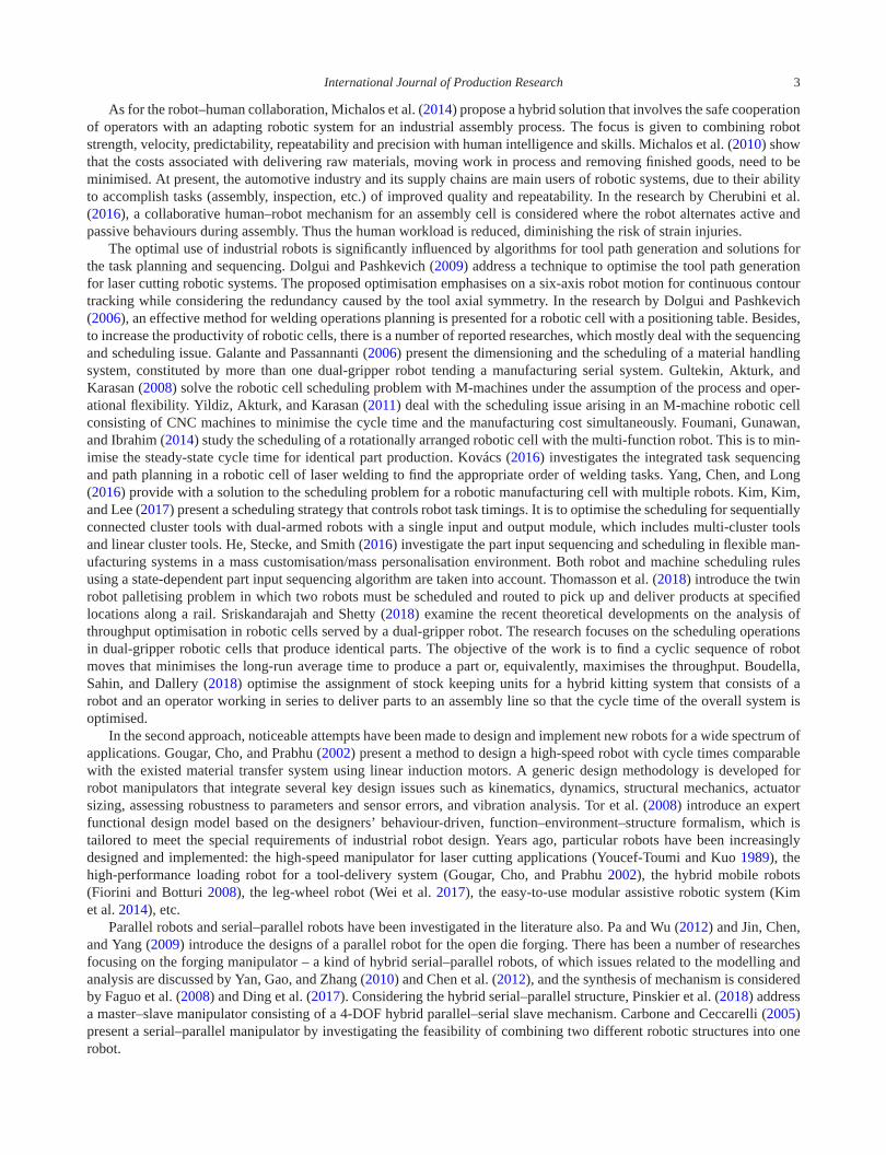
Figure 5. The mechanism of the robot arm and its design: (a) schematic diagram; (b) 3D design model; (c) 3D design model (backview).
considerable because the configurations PPP and PPR equivalent to the configuration PP, and the configurations RPP andPRP are impossible to orient the end link in the horizontal direction.
It is worth to note that if two parallel links are added to the configuration RRR, a particular configuration RR + isobtained as shown in Figure 4(f). Particularly, this configuration has only two DOFs. By using this configuration, not onlythe two movements 2 and 3 of the workpiece can be performed but also the required orientation of the end-effector isyielded.
As shown in Table 1, the most important advantage of the configurations PP and RR + is that they have only two DOFsin comparison with the three DOFs configurations. This reduces the number of actuators and the complexity of the controlsystem. As compared to the configuration RR + , the configuration PP has some disadvantages. To perform a movement ofa workpiece in the vertical plane, the combination of two translational movements produced by the configuration PP is lessflexible than the combination of two rotational movements by the configuration RR + . Furthermore, the length parameterof the second link of the PP structure is designed which depends on the distance existed between the furnace and the pressmachine requires, and a counterweight could be added to the link. Fortunately, the use of configuration RR + overcomes allof the mentioned weak points. The two rotational joints make it more flexible to move the workpiece in the vertical plane.The addition of two parallel links increases the structural stiffness and makes it a better payload-to-weight ratio. In addition,two hydraulic cylinders are able to use as auxiliary links to reinforce the structural rigidity of the entire robot (Figure 5c).Moreover, there is no counterweight needed to balance the shaking force.
Finally, the configuration RR + is selected to complete the kinematic chain of the arm mechanism, of which theschematic diagram is presented in Figure 5(a), and the 3D design model is shown in Figure 5(b and c). Note that thejoint number 5 is passive; there is no actuator needed for driving this joint.
The 3D simulation model of the designed robot is depicted in Figure 6.
5. Validation and testing
In this section, validation procedures for the designed robot are investigated. The kinematic modelling and analysis issummarised to validate the kinematic performance of the arm, and to select proper parameters for links 3 and 4. The quasi-static model is formulated to analyse the applied torques imposing on the system. Thus the loading capability of the selectedhydraulic cylinders can be assessed. In addition, the deflection of the arm end link is checked through a simulation model.Finally, functional tests and cycle time analysis are carried out to demonstrate the effectiveness of the implemented robot.

8 C. A. My et al.
Figure 6. 3D model of the designed robot in workspace.
Note that the quasi-static analysis, the real robot implementation, the testing procedures and experiments carrying out onthe implemented robot are the main and important contents. The kinematic analysis and the elastic displacement simulationof the last link that are relevant to previous papers (My and Parnichkun 2015; My 2016) are summarised with the purposeof completing the overall validation procedure as a whole.
5.1. Kinematic modelling and analysis
Kinematic modelling
On the kinematic model (Figure 7), O0 ≡ (O0x0y0z0) is defined as the reference frame; O1, O2, . . . , and O6 are the linkframes, correspondingly; q = [
d1 q2 q3 q4 q5 q6]T
is the vector of joint variables; ai and αi are the kinematical andgeometrical parameters of the link indexed i. The coordinate systems 1’ and 5’ are added to write all the homogeneoustransformation matrices of the whole system in the same formulation by Denavit–Hartenberg, Hji(qi, di, ai, αi). The matrixHji characterises the homogeneous motion of the frame indexed i with respect to the preceded frame indexed j. Note thatthe joint 5 is passive, so q5 is a dependent joint variable which relates to q3 and q4 in the following constraint equation:
q5 = −q3 − q4 − π
2. (1)
In the reference frame, the homogeneous transformation matrix of the end-effector can be calculated as
H0E = H01′(d1)H1′1H12(q2)H23(q3)H34(q4)H45′(q5)H5′5H56(q6). (2)
In matrix form, (2) can be rewritten as
H0E =[A(q) r(q)
0 1
], (3)
where A(q) is the rotation matrix and r(q) is the translation vector of the end-effector. Equation (3) describes the forwardkinematic relationship of the robot. If we denote pE = [
xE yE zE γ β]T
representing the general position of the end-effector in O0, where γ is the yaw angle and β is roll angle of the end-effector, (3) can be rewritten as the followingequation:
pE = f(q). (4)
Equation (4) has five independent variables. Substituting (1) into (4), and solving for pE yields
pE =
⎡⎢⎢⎢⎢⎣
cos q2[a4 cos(q3 + q4) + a3 cos q3 + a2 + d5 + d6]a4 sin(q3 + q4) + a3 sin q3 + a1 − a5 + d2
− sin q2[a4 cos(q3 + q4) + a3 cos q3 + a2 + d5 + d6] + d1
q2
q6
⎤⎥⎥⎥⎥⎦ . (5)
Equation (5) is the forward kinematic equation for the arm.

International Journal of Production Research 9
Figure 7. Kinematical model.
Inverse kinematics
Based on (4), the value of joint variables is found out by solving the inverse function q = f−1(pE). Thus the analyticalsolution of the inverse kinematics is yielded as follows:
⎡⎢⎢⎢⎢⎣
d1
q2
q3
q4
q6
⎤⎥⎥⎥⎥⎦ =
⎡⎢⎢⎢⎢⎢⎢⎢⎢⎣
xE tan q2 + zE
γ
tan−1(
−b+√b2−4ac
2a
)cos−1
((xE
cos q2−A
)2+(yE−B)2−a23−a2
4
2a3a4
)
β
⎤⎥⎥⎥⎥⎥⎥⎥⎥⎦
, (6)
where A = a2 + d5 + d6; B = a1 − a5 + d2; a = −(yE − B)2 + (a4 cos q4 + a3)2; b = 2a4 sin q4(a4 cos q4 + a3);
c = −(yE − B)2 + a24sin2q4.
Equation (6) shows that for any point pE = [xE yE zE γ β
]Tgiven in the workspace, the value of joint variables
can be determined analytically. By implementing (6), for the case of the heated workpiece transfer, the time history of jointdisplacements d1(t), q2(t), q3(t), q4(t) and q6(t) are calculated and shown in Figure 8. In this implementation, the geo-metric parameters of the links are given as a1 = 0.11 m, d2 = 0.25 m, a2 = 0.1 m,a3 = 0.73 m, a4 = 0.63 m, a5 = 0.18 m,d5 = 0.03 m and d6 = 0.43 m. Note that, Spline function in Matlab programming language is utilised to interpolate thetrajectory of the end-effector in the time domain.
By using this inverse kinematic analysis, for any given task assigned to the designing robot, the operation of the robot canbe demonstrated and the feasibility of the joint variables varying can be checked as well. It is essential for the robot programto control the end-effector moving at a required velocity along the desired trajectory in the workspace. It is important thatthe path planning and the kinematic analysis also simulate and validate the period of time needed for the transferring theheated workpiece. At the given velocity s(t) = 0.15 m/s, the transferring time period is 15 s.
Selection of geometric parameters of links
For the designed Robot, the geometric parameters of links 3 and 4 play the most important role since the total mass andinertia of the Robot are significantly effected by the links’ mass and inertia. In order to choose the proper value of the

10 C. A. My et al.
Figure 8. Time history of joint variables.
Figure 9. The manipulability index versus ka = a4/a3.
lengths of links 3 and 4, the analysis of the kinematic manipulability index, ω =√
det(JEJTE), where JE = ∂PE
∂q , is taken intoaccount. For the Robot design, the index is calculated as ω = a3a4|sin q4 cos q2|.
In essence, the index ω indicates of how close the Robot configuration is to the singularity. The value of ω depends onthe value of variables q2, q4 but not on the other variables d1, q3, and q6. The Robot will operate at maximum dexterity(ω → max) if q2 = 0 and q4 = −π/2. To maintain the dexterity level, the value of q2 → ±π/2 and q4 → 0 should notbe selected as the range of rotation of joint 2 and joint 4. In addition, it is also shown that the index ω depends on thegeometric parameters a3 and a4. Figure 9 shows that the value of ω varies along with the ratio of the length of links 4 and 3,ka = a4/a3, in the case that a3 + a4 = const and q2 is given. The dexterity of the Robot is influenced by the value of ka. If abigger ka is selected, the value of ω will increase, but the stability margin of the system could be decreased. This is becausethe horizontal distance from the gravity centre of link 4 to O′
1 and the link’s mass and inertia increase. If ka decreases, thevalue of the lower limitation of q4 must be extended to maintain the dexterity of the Robot. Hence, the dexterity and thestability of the designed Robot must be taken into account simultaneously by selecting a suitable value of ka. To make atrade-off between manipulability and stability, the lengths of links 3 and 4 are chosen as a3 = 0.73 m and a4 = 0.63 m; thelower limitation of q4 is checked with q4 min = −1.971 rad.
5.2. Quasi-static analysis
Obviously, for arms of high load capacity, computation of the applied torques/forces required to bear the heavy payload andthe gravity forces of links is significant for the selection and validation of actuators. In this section, a quasi-static model is

International Journal of Production Research 11
formulated and analysed to evaluate the applied torques/forces imposing on the active joints of the designed robot arm. Theobtained value of the torques/forces is then employed to validate the geometric parameters and the operating pressure oftwo main hydraulic cylinders driving the joint numbers 3 and 4.
As for the designed robot arm, the vector of applied torques/forces τ = [F1 τ2 τ3 τ4 τ6
]T, imposing on five active
joints, can be computed as
τ = JTp pp +
6∑i=1
JTi pi, (7)
where pp is the payload imposing at the end arm point cp(q); piis the gravity force acting at the mass centroid ci(q) of the
link i; Jp = ∂cp(q)
∂q and Ji = ∂ci(q)
∂q .Note that the vector τ in the above expression does not account for friction. They are the net torques/forces that balance
the payload and the gravity forces of links.Equation (7) can be proved by using the Principle of Virtual Work. Consider virtual displacements at individual joints,
δq = [δd1 δq2 δq3 δq4 δq6
]T, and a virtual displacement at the arm tip, δpp. The virtual work δW done by the forces
and moments is given by
δW = τTδq − pTpδpp −
6∑i=1
pTi δpi. (8)
Substituting the differential relationships δpp = Jpδq and δpi = Jiδq into (8) yields
δW =(
τ − JTp pp −
6∑i=1
JTi pi
)T
δq. (9)
Therefore, for the above virtual work to vanish for arbitrary virtual displacements we must have
τ − JTp pp −
6∑i=1
JTi pi = 0. (10)
Note that ci(q) is determined with respect to the frame Oi in the kinematic chain. Suppose that cp ≡ pE, the Jacobian Jp iscomputed as Jp = ∂f(q)
∂q .Equation (13) can be evaluated for any configuration of the robot in the configuration space. Note that when the arm
picks and lifts up a heated workpiece from the table of the furnace (the task B1), the arm tip reaches to the farthest point,and the effect of the gravity forces on the system maximises. For this critical configuration, the applied torques imposingon joints 3 and 4 are calculated asτ3 = 1167.4 Nm, and τ4 = 1, 233.29 Nm where pp = 600 N, p1 = 4812.3 N, p2 = 813 N,p3 = 506.4 N, p4 = 583.7 N, p5 = 376.5 N and p6 = 730.3 N. To meet the calculated torques τ3 and τ4 as required, hydrauliccylinders having the bore diameter D = 80 mm and using the operating pressure Poil ≥ 200 bar can be selected for drivingthe joints 3 and 4.
5.3. Structural analysis of the end-effector
The deformation and stress contribution of the end-effector need to be investigated because the cross section of the gripergeometry is smallest, as compared with the cross sections of links 3 and 4; the end-effector grips directly onto the heavyworkpiece. Also, links 3 and 4 are actuated by strong hydraulic cylinders. By using the FEM integrated in CAE softwareAutodesk Inventor (ANSYS Mechanical), the static stress and displacement distribution on the end-effector are computedand simulated (Figure 10). Consequently, the maximum value of the stress and the deflection of the end-effector are deter-mined to examine the safety factor and the loading capability of the robot. The end-effector is acted on by the external forcespp = 600 N. Other initial conditions required for the simulation running are inputted into the model.
The simulation results show that the maximum stress is 31.21 MPa which is much lower than the yield strength of thedesignated material, σ = 99 MPa; the minimum safety factor is 3.15 which is greater than 2.73 – the allowed safety factor.These results show the loading capacity of the designed end-effector with respect to its material and geometry. The maximumvalue of the displacement is 0.3237 mm. This is also meaningful in constructing the control algorithm and program. Theprogrammer should consider and compensate this value inside the controller to increase the accuracy of the robot gripper.

12 C. A. My et al.
Figure 10. Displacement of the end-effector.
Figure 11. Pictures of the implemented robot arm.
5.4. Functional test and cycle time analysis
Figure 11 shows pictures of the implemented robot with the following characteristics:
Robot footprint [mm] 1008 × 757Controlled axes 5Repeatability [mm] ± 4.6Mechanical weight [kg] 785Maximum speedJoint 1 [m/s] 0.8Joint 2 [°/s] 20Joint 3 [°/s] 14Joint 4 [°/s] 14Joint 6 [°/s] 45Voltage 50/60 Hz 3 phase [V] 380Voltage 50/60 Hz 1 phase [V] 220Average power consumption [kW] 8
A series of functional tests performed on the robot arm, in which a comparison is carried out among numerical results,simulation results and experimental results giving a good match. The transforming time of a hot workpiece from the furnaceto the die on the press machine is 20.4 s which is greater than 15.0 s – the simulation value obtained by the inverse kinematicsanalysis. However, this experimental value is still much lower than the allowed value (25.0 s). When the gripper grips andlifts up a workpiece weighted 60 kg, the measured deflection of the arm tip is 0.24 mm which is lower than the value yieldedfrom the simulation scenarios (0.3237 mm).
In the experimental tests, the dataset for production cycle time analysis is collected, in which nine observations (samplesize = 9) are carried out. For this serial production, each production cycle is divided into six steps, and the time neededfor each step is measured correspondingly. Finally, the average production cycle time is determined. Table 2 shows acomparison of the manual cycle time and the auto cycle time. By using the robot, the average cycle time is reduced by27.7% as compared with the average cycle time of the manual method.

International Journal of Production Research 13
Table 2. Cycle time comparison.
Manual cycle time (s) Auto cycle time (s)
Average processing time of the machines (heating and pressing) 103.5 103.5Average loading time of raw material 6 3.6Average transferring time to the heating furnace 22 17.8Average transferring time from the furnace to the press machine 25 20.4Average loading and unloading time of the part on the press machine 120 54.6Total 276.5 199.9
6. Conclusion
A cost-effective robotised solution of automated workpiece handling for hot forging press manufacturing has been suc-cessfully investigated and implemented. The testing results show that the designed robotic system is capable of replacingworkers to pickup, transfer and place workpiece among given places of the manufacturing system. By applying the solution,the average cycle time of the production has been reduced by 27.7% approximately.
In particular, a special mechanism of the robot arm was synthesised. By adding two successive parallel links in betweena usual serial kinematic chain of the manipulator, the DOFs of the mechanism have been reduced, and the orientation of theend-effector has been optimised. The computational validations and experimental tests have shown that the average valueof the transferring time measured by experiments (20.4 s) was greater than the value calculated by simulation (15 s), but itwas still less than the allowed limitation (25 s); the hydraulic cylinders (with bore diameter D = 80 mm and oil pressurePoil = 200 bar) driving the joints 3 and 4 of the designed robot were properly selected; the maximum static deflection ofthe end-effector was calculated as 0.3237 mm which was greater than the value yielded by the experimental test (0.24 mm);the minimum safety factor was 3.85 which was greater than 2.73 – the allowed safety factor. These results demonstrate theloading capacity of the designed end-effector with respect to its material and geometry.
Dynamic modelling and analysis, and dynamic modelling-based optimisation of geometric parameters for links of therobot will be the future work of this research. The effects of the temperature field, vibrations and other dynamic factors onthe optimisation of the designed robot will be considered in the future work as well.
Disclosure statementNo potential conflict of interest was reported by the authors.
FundingThis research is funded by Vietnam National Foundation for Science and Technology Development (NAFOSTED) under grant number107.04-2017.09.
ReferencesBoudella, M. E. A., E. Sahin, and Y. Dallery. 2018. “Kitting Optimisation in Just-in-Time Mixed-Model Assembly Lines: Assigning Parts
to Pickers in a Hybrid Robot–Operator Kitting System.” International Journal of Production Research 48, 1–20.Carbone, G., and M. Ceccarelli. 2005. “A Serial-Parallel Robotic Architecture for Surgical Tasks.” Robotica 23 (3): 345–354.Chen, G., H. Wang, K. Zhao, and Lin Z. 2012. “Modular Calculation of the Jacobian Matrix and Its Application to the Performance
Analyses of a Forging Robot.” Advanced Robotics 23 (10): 1261–1279.Cherubini, A., R. Passama, A. Crosnier, A. Lasnier, and P. Fraisse. 2016. “Collaborative Manufacturing with Physical Human–Robot
Interaction.” Robotics and Computer-Integrated Manufacturing 40: 1–13.Denkena, B., and T. Lepper. 2015. “Enabling an Industrial Robot for Metal Cutting Operations.” Procedia CIRP 35: 79–84.Ding, H., Z. Feng, W. Yang, and A. Kecskeméthy. 2017. “Structure Synthesis of 6-DOF Forging Manipulators.” Mechanism and Machine
Theory 111: 135–151.Dolgui, A., and A. Pashkevich. 2006. “Cluster-level Operations Planning for the out-of-Position Robotic Arc-Welding.” International
Journal of Production Research 44 (4): 675–702.Dolgui, A., and A. Pashkevich. 2009. “Manipulator Motion Planning for High-Speed Robotic Laser Cutting.” International Journal of
Production Research 47 (20): 5691–5715.Faguo, Y., Feng G., Qiaoshuo S., Hao G., Yong Z.. 2008. “Structure Synthesis for Forging Manipulators.” In Proceedings of 7th World
Congress on Intelligent Control and Automation,Chongqing, People’s Republic of China, 400–403.Fiorini, P., and D. Botturi. 2008. “Introducing Service Robotics to the Pharmaceutical Industry.” Intelligent Service Robotics 1 (4):
267–280.

14 C. A. My et al.
Forge, S., and C. Blackman. 2010. Helping hand for Europe: The competitive outlook for the EU robotics industry.http://publications.jrc.ec.europa.eu/repository/bitstream/111111111/22080/1/jrc61539.pdf.
Foumani, M., I. Gunawan, and Y. Ibrahim. 2014. “Scheduling Rotationally Arranged Robotic Cells Served by a Multi-Function Robot.”International Journal of Production Research 52 (13): 4037–4058.
Galante, G., and G. Passannanti. 2006. “Minimizing the Cycle Time in Serial Manufacturing Systems with Multiple Dual-Gripper Robots.”International Journal of Production Research 44 (4): 639–652.
Garcia, E., M. A. Jimenez, P. G. De Santos, and M. Armada. 2007. “The Evolution of Robotics Research.” IEEE Robotics & AutomationMagazine 14 (1): 90–103.
Gougar, H., S. Cho, and V. Prabhu. 2002. “High Performance Loading Robot Design for a Tool-Delivery System.” International Journalof Production Research 40 (14): 3401–3424.
Gultekin, H., M. S. Akturk, and O. E. Karasan. 2008. “Scheduling in Robotic Cells: Process Flexibility and Cell Layout.” InternationalJournal of Production Research 46 (8): 2105–2121.
He, Y., K. E. Stecke, and M. L. Smith. 2016. “Robot and Machine Scheduling with State-Dependent Part Input Sequencing in FlexibleManufacturing Systems.” International Journal of Production Research 54 (22): 6736–6746.
Huang, H. K., and G. C. I. Lin. 2002. “Development of a Dual-Robot System for Prototype Production.” International Journal ofProduction Research 40 (15): 3751–3764.
Jin, Y., I.-M. Chen, and G. Yang. 2009. “Kinematic Design of a Family of 6-DOF Partially Decoupled Parallel Manipulators.” Mechanismand Machine Theory 44 (5): 912–922.
Karsak, E. E. 2008. “Robot Selection Using an Integrated Approach Based on Quality Function Deployment and Fuzzy Regression.”International Journal of Production Research 46 (3): 723–738.
Kentli, A., and A. K. Kar. 2011. “A Satisfaction Function and Distance Measure Based Multi-Criteria Robot Selection Procedure.”International Journal of Production Research 49 (19): 5821–5832.
Kim, D. K., H. J. Kim, and T. E. Lee. 2017. “Optimal Scheduling for Sequentially Connected Cluster Tools with Dual-Armed Robots anda Single Input and Output Module.” International Journal of Production Research 55 (11): 3092–3109.
Kim, D. J., Z. Wang, N. Paperno, and A. Behal. 2014. “System Design and Implementation of UCF-Manus – an Intelligent AssistiveRobotic Manipulator.” IEEE/ASME Transactions on Mechatronics 19 (1): 225–237.
Kovács, A. 2016. “Integrated Task Sequencing and Path Planning for Robotic Remote Laser Welding.” International Journal ofProduction Research 54 (4): 1210–1224.
Liu, H. C., M. L. Ren, J. Wu, and Q. L. Lin. 2014. “An Interval 2-Tuple Linguistic MCDM Method for Robot Evaluation and Selection.”International Journal of Production Research 52 (10): 2867–2880.
Michalos, G., S. Makris, N. Papakostas, D. Mourtzis, and G. Chryssolouris. 2010. “Automotive Assembly Technologies Review: Chal-lenges and Outlook for a Flexible and Adaptive Approach.” CIRP Journal of Manufacturing Science and Technology 2 (2):81–91.
Michalos, G., S. Makris, J. Spiliotopoulos, I. Misios, P. Tsarouchi, and G. Chryssolouris. 2014. “ROBO-PARTNER: Seamless Human-Robot Cooperation for Intelligent, Flexible and Safe Operations in the Assembly Factories of the Future.” Procedia CIRP 23:71–76.
My, C. A. 2016. “Inverse Kinematics of a Serial-Parallel Robot Used in hot Forging Process.” Vietnam Journal of Mechanics 38 (2):81–88.
My, C. A., and M. Parnichkun. 2015. “Kinematics Performance and Structural Analysis for the Design of a Serial-Parallel Manip-ulator Transferring a Billet for a hot Extrusion Forging Process.” International Journal of Advanced Robotic Systems 12(12): 186.
Olsson, T., M. Haage, H. Kihlman, R. Johansson, K. Nilsson, A. Robertsson, M. Björkman, R. Isaksson, G. Ossbahr, and T. Brogårdh.2010. “Cost-Efficient Drilling Using Industrial Robots with High-Bandwidth Force Feedback.” Robotics and Computer-IntegratedManufacturing 26 (1): 24–38.
Pa, P. S., and C. M. Wu. 2012. “Design of a Hexapod Robot with a Servo Control and a man-Machine Interface.” Robotics and Computer-Integrated Manufacturing 28 (3): 351–358.
Pham, D. T., and S. H. Yeo. 1991. “Strategies for Gripper Design and Selection in Robotic Assembly.” International Journal of ProductionResearch 29 (2): 303–316.
Pinskier, J., B. Shirinzadeh, L. Clark, and Y. Qin. 2018. “Development of a 4-DOF Haptic Micromanipulator Utilizing a Hybrid Parallel-Serial Flexure Mechanism.” Mechatronics 50: 55–68.
Sriskandarajah, C., and B. Shetty. 2018. “A Review of Recent Theoretical Development in Scheduling Dual-Gripper Robotic Cells.”International Journal of Production Research 56 (1–2): 817–847.
Su, J., H. Qiao, C. Liu, Y. Song, and A. Yang. 2017. “Grasping Objects: The Relationship Between the Cage and the Form-ClosureGrasp.” IEEE Robotics & Automation Magazine 24 (3): 84–96.
Thomasson, O., M. Battarra, G. Erdogan, and G. Laporte. 2018. “Scheduling Twin Robots in a Palletising Problem.” International Journalof Production Research 56 (1–2): 518–542.
Tilley, J. 2017. Automation, robotics, and the factory of the future. https://www.mckinsey.com/business-functions/operations/our-insights/automation-robotics-and-the-factory-of-the-future.
Tor, S. B., S. G. Lee, G. A. Britton, and W. Y. Zhang. 2008. “Knowledge-Based Functional Design of Industrial Robots.” InternationalJournal of Production Research 46 (16): 4501–4519.

International Journal of Production Research 15
Wei, Z., G. Song, G. Qiao, Y. Zhang, and H. Sun. 2017. “Design and Implementation of a leg-Wheel Robot: TRANSLEG.” Journal ofMechanisms and Robotics 9 (5): 051001–051001-9.
Yan, C., F. Gao, and Y. Zhang. 2010. “Kinematic Modelling of a Serial–Parallel Forging Manipulator with Application to Heavy-DutyManipulations.” Mechanics Based Design of Structures and Machines 38 (1): 105–129.
Yang, Y., Y. Chen, and C. Long. 2016. “Flexible Robotic Manufacturing Cell Scheduling Problem with Multiple Robots.” InternationalJournal of Production Research 54 (22): 6768–6781.
Yildiz, S., M. S. Akturk, and O. E. Karasan. 2011. “Bicriteria Robotic Cell Scheduling with Controllable Processing Times.” InternationalJournal of Production Research 49 (2): 569–583.
Youcef-Toumi, K., and A. T. Y. Kuo. 1989. “Design and Control of a High-Speed Direct-Drive Manipulator.” International Journal ofProduction Research 27 (3): 375–394.