ARM® Keil® MDK 5 IDE for MSP432 - DigChip
33
User's Guide SLAU590 – March 2015 ARM® Keil® MDK 5 IDE for MSP432™ This user's guide describes the use of the Keil ® MDK 5 Integration Development Environment (IDE) with the MSP432™ low-power microcontrollers. Contents 1 Installing Keil uVision 5 ..................................................................................................... 3 2 Installing the MSP432 Device Family Pack .............................................................................. 3 3 Creating an MSP432 Project ............................................................................................... 7 4 Opening an MSP432 Project ............................................................................................. 12 5 Additional MSP432 Examples and Documentation .................................................................... 13 6 Debugging the Application ................................................................................................ 13 7 Frequently Asked Questions .............................................................................................. 31 8 Additional Keil MDK-ARM Information................................................................................... 32 9 References .................................................................................................................. 32 List of Figures 1 Keil Pack Unzip Tool ........................................................................................................ 3 2 License Agreement .......................................................................................................... 4 3 Device Family Pack Has Been Installed Successfully .................................................................. 4 4 Launching the Pack Installer ............................................................................................... 5 5 Installing the MSP432 Device Family Pack .............................................................................. 6 6 Create New Project .......................................................................................................... 7 7 Assign Project Name ........................................................................................................ 7 8 Select MSP432P401R Device ............................................................................................. 8 9 Add MSP432 Run-Time Environment Components to the Project .................................................... 9 10 Empty Project ................................................................................................................ 9 11 Add New Item to Project .................................................................................................. 10 12 Add User Code Template ................................................................................................. 10 13 Compiling the Project ...................................................................................................... 11 14 Opening a Project .......................................................................................................... 12 15 Choosing a Project to Import ............................................................................................. 13 16 Project Options ............................................................................................................. 14 17 Select J-Link Debug Probe ............................................................................................... 14 18 Go to J-Link Debug Probe Settings Window ........................................................................... 15 19 Enable J-Link Download Options ........................................................................................ 16 20 J-Link Download Function Configuration ................................................................................ 17 21 Start Debug Session ....................................................................................................... 17 22 Messages During Debug Session Startup .............................................................................. 18 23 Debug Session Halted at main() ......................................................................................... 19 24 Using J-Link Commander to Enable Power Output to Target System .............................................. 19 25 Launch J-Link Control Panel .............................................................................................. 20 26 J-Link Control Panel ....................................................................................................... 21 MSP432, E2E, LaunchPad are trademarks of Texas Instruments. Keil is a registered trademark of ARM Ltd. 1 SLAU590 – March 2015 ARM® Keil® MDK 5 IDE for MSP432™ Submit Documentation Feedback Copyright © 2015, Texas Instruments Incorporated This datasheet has been downloaded from http://www.digchip.com at this page
-
Upload
khangminh22 -
Category
Documents
-
view
0 -
download
0
Transcript of ARM® Keil® MDK 5 IDE for MSP432 - DigChip
User's GuideSLAU590–March 2015
ARM® Keil® MDK 5 IDE for MSP432™
This user's guide describes the use of the Keil® MDK 5 Integration Development Environment (IDE) withthe MSP432™ low-power microcontrollers.
Contents1 Installing Keil uVision 5 ..................................................................................................... 32 Installing the MSP432 Device Family Pack .............................................................................. 33 Creating an MSP432 Project ............................................................................................... 74 Opening an MSP432 Project ............................................................................................. 125 Additional MSP432 Examples and Documentation .................................................................... 136 Debugging the Application ................................................................................................ 137 Frequently Asked Questions.............................................................................................. 318 Additional Keil MDK-ARM Information................................................................................... 329 References .................................................................................................................. 32
List of Figures
1 Keil Pack Unzip Tool ........................................................................................................ 32 License Agreement .......................................................................................................... 43 Device Family Pack Has Been Installed Successfully .................................................................. 44 Launching the Pack Installer ............................................................................................... 55 Installing the MSP432 Device Family Pack .............................................................................. 66 Create New Project.......................................................................................................... 77 Assign Project Name ........................................................................................................ 78 Select MSP432P401R Device ............................................................................................. 89 Add MSP432 Run-Time Environment Components to the Project.................................................... 910 Empty Project ................................................................................................................ 911 Add New Item to Project .................................................................................................. 1012 Add User Code Template ................................................................................................. 1013 Compiling the Project ...................................................................................................... 1114 Opening a Project .......................................................................................................... 1215 Choosing a Project to Import ............................................................................................. 1316 Project Options ............................................................................................................. 1417 Select J-Link Debug Probe ............................................................................................... 1418 Go to J-Link Debug Probe Settings Window ........................................................................... 1519 Enable J-Link Download Options ........................................................................................ 1620 J-Link Download Function Configuration................................................................................ 1721 Start Debug Session ....................................................................................................... 1722 Messages During Debug Session Startup .............................................................................. 1823 Debug Session Halted at main() ......................................................................................... 1924 Using J-Link Commander to Enable Power Output to Target System .............................................. 1925 Launch J-Link Control Panel.............................................................................................. 2026 J-Link Control Panel ....................................................................................................... 21
MSP432, E2E, LaunchPad are trademarks of Texas Instruments.Keil is a registered trademark of ARM Ltd.
1SLAU590–March 2015 ARM® Keil® MDK 5 IDE for MSP432™Submit Documentation Feedback
Copyright © 2015, Texas Instruments Incorporated
This datasheet has been downloaded from http://www.digchip.com at this page

www.ti.com
27 J-Link Script Detecting That the Device Has Been Secured ......................................................... 2128 Device Has Been Unlocked and Erased ................................................................................ 2129 Project Options ............................................................................................................. 2230 Selecting the ULINK Pro Debug Probe.................................................................................. 2231 Selecting ULINK Pro Download Options ................................................................................ 2332 Select ULINK Pro Download Function................................................................................... 2333 Start Debug Session ....................................................................................................... 2434 Debug Session Successfully Started and Halted at main()........................................................... 2535 Dialog Box Asking to Perform a Factory Reset ........................................................................ 2536 Project Options ............................................................................................................. 2637 Selecting the CMSIS-DAP Debug Probe................................................................................ 2638 Selecting CMSIS-DAP Settings .......................................................................................... 2739 Select ULINK Pro Download Function................................................................................... 2740 Start Debug Session ....................................................................................................... 2841 Debug Session Successfully Started and Halted at main()........................................................... 2942 Dialog Box Asking to Perform a Factory Reset ........................................................................ 3043 Changing Debugger Setting to SWD .................................................................................... 31
Read This First
How to Use This User's GuideThis User's Guide describes only the features of the Keil MDK 5 IDE that are specific to the MSP432 low-power microcontrollers. It does not fully describe the MSP432 microcontrollers or the completedevelopment software and hardware systems. For details on these items, see the appropriate TIdocuments listed in Important MSP432 Documents on the Web.
Important MSP432 Documents on the WebThe primary sources of MSP432 information are the device-specific data sheets and user's guides. TheMSP432 web site (www.ti.com/msp432) contains the most recent version of these documents.
Documents describing the Keil MDK 5 IDE can be found on www.keil.com. The Texas Instruments E2E™Community support forums at e2e.ti.com can provide additional help.
Documentation for third-party tools, such as the Keil ULINK2 and ULINK Pro debug probes or Segger J-Link debug probe, can usually be found on the respective third-party website.
If You Need AssistanceSupport for the MSP432 devices and the hardware development tools is provided by the TexasInstruments Product Information Center (PIC). Contact information for the PIC can be found on the TI website at www.ti.com/support. The Texas Instruments E2E Community support forums for the MSP432 ate2e.ti.com provide open interaction with peer engineers, TI engineers, and other experts. Additionaldevice-specific information can be found on the MSP432 web site at www.ti.com/msp432.
2 ARM® Keil® MDK 5 IDE for MSP432™ SLAU590–March 2015Submit Documentation Feedback
Copyright © 2015, Texas Instruments Incorporated
www.ti.com Installing Keil uVision 5
1 Installing Keil uVision 5The Keil uVision 5 IDE can be obtained from Keil website at www.keil.com. Note that MSP432 low-powermicrocontrollers are supported by Keil uVision 5 and higher versions. Previous versions do not supportMSP432, and might not be compatible with MSP432 Device Family Packs.
2 Installing the MSP432 Device Family PackThe Keil uVision 5 IDE does not come with pre-installed device support. To add MSP432 support to theIDE users can either download the MSP432 Device Family Pack from the TI or Keil websites or install thepack using the Keil Pack Installer.
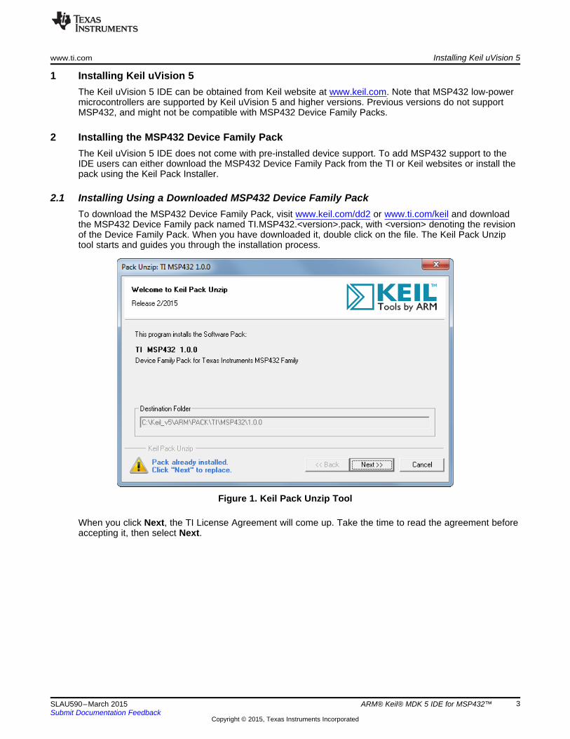
2.1 Installing Using a Downloaded MSP432 Device Family PackTo download the MSP432 Device Family Pack, visit www.keil.com/dd2 or www.ti.com/keil and downloadthe MSP432 Device Family pack named TI.MSP432.<version>.pack, with <version> denoting the revisionof the Device Family Pack. When you have downloaded it, double click on the file. The Keil Pack Unziptool starts and guides you through the installation process.
Figure 1. Keil Pack Unzip Tool
When you click Next, the TI License Agreement will come up. Take the time to read the agreement beforeaccepting it, then select Next.
3SLAU590–March 2015 ARM® Keil® MDK 5 IDE for MSP432™Submit Documentation Feedback
Copyright © 2015, Texas Instruments Incorporated

Installing the MSP432 Device Family Pack www.ti.com
Figure 2. License Agreement
After the Pack Unzip tool has copied the device family files into the uVision IDE installation directory, thePack Unzip tool will finish (see Figure 3).
Figure 3. Device Family Pack Has Been Installed Successfully
If the tool reports an error, check whether the Device Family Pack has been downloaded correctly, andwhether the uVision IDE directory is writeable.
4 ARM® Keil® MDK 5 IDE for MSP432™ SLAU590–March 2015Submit Documentation Feedback
Copyright © 2015, Texas Instruments Incorporated

www.ti.com Installing the MSP432 Device Family Pack
2.2 Installing Using the Keil Pack InstallerTo install using the Keil Pack Installer open up the Keil uVision IDE. To launch the Keil Pack Installer go toProject -> Manage -> Pack Installer.
Figure 4. Launching the Pack Installer
After the pack installer has been launched, locate "Texas Instruments::MSP432" from the pack listing andchoose "Install" to let the IDE download and install the MSP432 Device Family Pack into the IDE.
5SLAU590–March 2015 ARM® Keil® MDK 5 IDE for MSP432™Submit Documentation Feedback
Copyright © 2015, Texas Instruments Incorporated

Installing the MSP432 Device Family Pack www.ti.com
Figure 5. Installing the MSP432 Device Family Pack
If the tool reports an error, check whether the uVision IDE directory is writeable.
6 ARM® Keil® MDK 5 IDE for MSP432™ SLAU590–March 2015Submit Documentation Feedback
Copyright © 2015, Texas Instruments Incorporated

www.ti.com Creating an MSP432 Project
3 Creating an MSP432 ProjectWhen starting uVision for the first time, create a project for the MSP432. Go to Project → New uVisionProject and click on the selection (see Figure 6).
Figure 6. Create New Project
A file dialog (see Figure 7) is displayed to prompt for the project name and location. Navigate to anappropriate directory on the computer, and then enter the project name (for example, myFirstProject).Click the Save button to create the project files.
Figure 7. Assign Project Name
After the project has been created, uVision IDE will prompt you to select the device you are going to useto apply device-specific settings to the project. Go to Texas Instruments → MSP432 Family →MSP432P and select the appropriate device from the list of available devices (see Figure 8).
7SLAU590–March 2015 ARM® Keil® MDK 5 IDE for MSP432™Submit Documentation Feedback
Copyright © 2015, Texas Instruments Incorporated

Creating an MSP432 Project www.ti.com
Figure 8. Select MSP432P401R Device
After the device has been selected, the run-time environment components can be added to the project(see Figure 9). If this step is skipped, the components can be added at a later point, or when additionalcomponents have been added through specific Software Packs, through the Manage Run-TimeEnvironment button in the uVision IDE.
Run-Time Environment components include device startup and header files, and Cortex-M genericfunctions and definitions that are part of the ARM CMSIS package.
To develop code for the MSP432, the selections for CMSIS → CORE and Device → Startup need to beenabled. Others are optional.
8 ARM® Keil® MDK 5 IDE for MSP432™ SLAU590–March 2015Submit Documentation Feedback
Copyright © 2015, Texas Instruments Incorporated

www.ti.com Creating an MSP432 Project
Figure 9. Add MSP432 Run-Time Environment Components to the Project
When you have finished the wizard by clicking the OK button, uVision will show the newly created projectcontaining two source code files:• startup_MSP432.s: Assembler file containing the interrupt vector table and a definition of all available
interrupt service routines, including the reset vector• system_MSP432.c: C file containing low-level device initialization functions, including a watchdog timer
halt command
Figure 10. Empty Project
9SLAU590–March 2015 ARM® Keil® MDK 5 IDE for MSP432™Submit Documentation Feedback
Copyright © 2015, Texas Instruments Incorporated

Creating an MSP432 Project www.ti.com
To start code development, a main() function is required. To create a source code file, right-click onSource Group 1, then select Add New Item to Group (see Figure 11).
Figure 11. Add New Item to Project
A wizard opens in which several types of files can be created. Along with the MSP432 Device FamilyPack, User Code Templates have been provided, so you can select between the BlinkLED code andempty main code. The templates include the msp.h family header file and use C header files that provideMSP430 backward compatibility.
Figure 12. Add User Code Template
After you have added a user code template to the code, the project is ready for compilation. Right-click onthe project and select Rebuild all target files from the context menu, or simply press F7 to rebuild alltarget files. If the project has been set up correctly, a compiler and linker output similar to the one shownin Figure 13 is displayed.
10 ARM® Keil® MDK 5 IDE for MSP432™ SLAU590–March 2015Submit Documentation Feedback
Copyright © 2015, Texas Instruments Incorporated

www.ti.com Creating an MSP432 Project
Figure 13. Compiling the Project
The project is now ready for upload to the device.
11SLAU590–March 2015 ARM® Keil® MDK 5 IDE for MSP432™Submit Documentation Feedback
Copyright © 2015, Texas Instruments Incorporated

Opening an MSP432 Project www.ti.com
4 Opening an MSP432 ProjectTo open a project first launch the uVision IDE. After the IDE launches click Project -> Open Project (seeFigure 14).
Figure 14. Opening a Project
After clicking "Open Project…", navigate to where the project is stored and double click the .uvprojx file toopen the project in the IDE (see Figure 15).
12 ARM® Keil® MDK 5 IDE for MSP432™ SLAU590–March 2015Submit Documentation Feedback
Copyright © 2015, Texas Instruments Incorporated

www.ti.com Additional MSP432 Examples and Documentation
Figure 15. Choosing a Project to Import
5 Additional MSP432 Examples and DocumentationThe Texas Instruments MSP team releases a software package called MSPWare that contains manysoftware examples, projects, documentation as well as application notes and training for all MSP devices.This includes example projects for Keil uVision that work with MSP432. For more information visitwww.ti.com/tool/mspware.
6 Debugging the ApplicationThe following debug probes have been tested successfully with MSP432 and uVision IDE.• Segger J-Link• Keil ULINK2 and ULINK Pro• XDS110-ET (using CMSIS-DAP)
If you want to use a debug probe that is not listed here, check with the vendor of the debug probe or withARM if you experience problems.
13SLAU590–March 2015 ARM® Keil® MDK 5 IDE for MSP432™Submit Documentation Feedback
Copyright © 2015, Texas Instruments Incorporated

Debugging the Application www.ti.com
6.1 Using Segger J-Link Debug ProbeTo use the Segger J-Link debug probe, right-click on the active project, then select Options for Target(see Figure 16).
Figure 16. Project Options
In the Target Options window, select the Debug pane (see Figure 17). From the pulldown menu on theright-hand side, select the J-Link debug probe.
Figure 17. Select J-Link Debug Probe
Next you need to move on to the debug probe specific settings by clicking on the Settings button next tothe debug probe (see Figure 18).
14 ARM® Keil® MDK 5 IDE for MSP432™ SLAU590–March 2015Submit Documentation Feedback
Copyright © 2015, Texas Instruments Incorporated

www.ti.com Debugging the Application
Figure 18. Go to J-Link Debug Probe Settings Window
In the Debug Probe Settings window (see Figure 19), make sure that both check boxes in the DownloadOptions box are checked.
15SLAU590–March 2015 ARM® Keil® MDK 5 IDE for MSP432™Submit Documentation Feedback
Copyright © 2015, Texas Instruments Incorporated

Debugging the Application www.ti.com
Figure 19. Enable J-Link Download Options
Go to the Flash Download pane to configure how the Flash memory should be erased, programmed,and/or verified. The settings shown in Figure 20 issue a Flash mass erase prior to Flash programming andverify the programmed image before enabling debug. Even though the "Erase Full Chip" is selected, thebootstrap loader (BSL) is not erased. To replace the BSL, choose "Erase Sectors" and place code in theBSL section of memory.
16 ARM® Keil® MDK 5 IDE for MSP432™ SLAU590–March 2015Submit Documentation Feedback
Copyright © 2015, Texas Instruments Incorporated

www.ti.com Debugging the Application
Figure 20. J-Link Download Function Configuration
After the Flash download has been configured, the Debug Session can be started. Go to Debug →Start/Stop Debug Session, or alternatively press Ctrl+F5.
Figure 21. Start Debug Session
17SLAU590–March 2015 ARM® Keil® MDK 5 IDE for MSP432™Submit Documentation Feedback
Copyright © 2015, Texas Instruments Incorporated
Debugging the Application www.ti.com
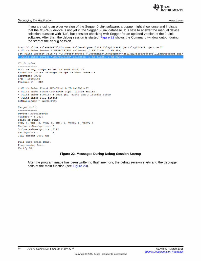
If you are using an older version of the Segger J-Link software, a popup might show once and indicatethat the MSP432 device is not yet in the Segger J-Link database. It is safe to answer the manual deviceselection question with "No", but consider checking with Segger for an updated version of the J-Linksoftware. After that, the debug session is started. Figure 22 shows the Command window output duringthe start of the debug session.
Figure 22. Messages During Debug Session Startup
After the program image has been written to flash memory, the debug session starts and the debuggerhalts at the main function (see Figure 23).
18 ARM® Keil® MDK 5 IDE for MSP432™ SLAU590–March 2015Submit Documentation Feedback
Copyright © 2015, Texas Instruments Incorporated

www.ti.com Debugging the Application
Figure 23. Debug Session Halted at main()
When you are using an MSP432 target socket board, you can benefit from the 5-V voltage output the J-Link is providing on pin 19 of its Cortex-M debug connector to power the MSP432 device. This optionneeds to be enabled through the J-Link Commander, a console application available from Segger, since itis not available from the IDE. After it is enabled, the debug probe will provide 5 V to the target system.Refer to the MSP432 Hardware User's Guide (SLAU571) how to configure the target socket board to usethe 5-V power supply to generate 3.3-V device voltage and to Segger's documentation how to enable thevoltage output.
Figure 24 shows the effect of the power on command, when applied in the J-Link Commander. Beforeexecuting the command, the measured target voltage is 0 V, and right after applying target power, 3.3 V isavailable as target voltage.
Figure 24. Using J-Link Commander to Enable Power Output to Target System
19SLAU590–March 2015 ARM® Keil® MDK 5 IDE for MSP432™Submit Documentation Feedback
Copyright © 2015, Texas Instruments Incorporated

Debugging the Application www.ti.com
Now you can download the program normally and debug using the Segger J-Link debug probe withuVision.
6.1.1 Working With Device SecurityIf you have disabled JTAG access on the device or are working on an application where you need tounlock a secure IP zone a J-Link Script needs to be added to the debug session to enable a factory reset.During a debug session launch the J-Link control panel by clicking on the J-Link icon in the status bar (seeFigure 25).
Figure 25. Launch J-Link Control Panel
After launching the J-Link control panel, add the MSP432 J-Link script provided in the Keil pack. Figure 26shows the location of the script file.
20 ARM® Keil® MDK 5 IDE for MSP432™ SLAU590–March 2015Submit Documentation Feedback
Copyright © 2015, Texas Instruments Incorporated

www.ti.com Debugging the Application
Figure 26. J-Link Control Panel
The J-Link script now runs at the launch of very debug session and every time code is downloaded to thedevice. If the device has been secured when trying to download code a dialog box pops up letting the userknow that the device is secured and can be erased.
Figure 27. J-Link Script Detecting That the Device Has Been Secured
Pressing "OK" on the dialog box issues a factory reset which erases any code present on the device andthen starts to download the compiled code. After the factory reset is a complete, a confirmation dialog boxis displayed (see Figure 28).
Figure 28. Device Has Been Unlocked and Erased
21SLAU590–March 2015 ARM® Keil® MDK 5 IDE for MSP432™Submit Documentation Feedback
Copyright © 2015, Texas Instruments Incorporated

Debugging the Application www.ti.com
6.2 Using Keil ULINK2 and ULINK Pro debug probeTo use Keil ULINK2 or ULINK Pro debug probes, right-click on the active project, then select Options forTarget.
Figure 29. Project Options
In the Target Options window, select the Debug pane. From the pulldown menu, select the ULINK2 orULINK Pro debug probe. Be careful to select the right debug probe, as the driver is different.
Figure 30. Selecting the ULINK Pro Debug Probe
In the Debug Probe Settings window (see Figure 31), make sure that both check boxes in the DownloadOptions box are checked.
22 ARM® Keil® MDK 5 IDE for MSP432™ SLAU590–March 2015Submit Documentation Feedback
Copyright © 2015, Texas Instruments Incorporated

www.ti.com Debugging the Application
Figure 31. Selecting ULINK Pro Download Options
Now move to Flash Download pane to configure the way the Flash memory should be erased,programmed, and/or verified. The settings shown in Figure 32 issue a Flash mass erase prior to Flashprogramming and verify the programmed image before enabling debug. Even though the "Erase Full Chip"is selected the Bootstrap Loader (BSL) is not erased. To replace the BSL choose "Erase Sectors" andplace code in the BSL section of memory.
Figure 32. Select ULINK Pro Download Function
23SLAU590–March 2015 ARM® Keil® MDK 5 IDE for MSP432™Submit Documentation Feedback
Copyright © 2015, Texas Instruments Incorporated

Debugging the Application www.ti.com
After the Flash download has been configured, the Debug Session can be started. Go to Debug →Start/Stop Debug Session, or alternatively press Ctrl+F5.
Figure 33. Start Debug Session
After the program image has been written to flash memory, the debug session starts and the debuggerhalts at the main function (see Figure 34).
24 ARM® Keil® MDK 5 IDE for MSP432™ SLAU590–March 2015Submit Documentation Feedback
Copyright © 2015, Texas Instruments Incorporated

www.ti.com Debugging the Application
Figure 34. Debug Session Successfully Started and Halted at main()
6.2.1 Working With Device SecurityIf you have disabled JTAG access on the device or are working on an application where you need tounlock a secure IP zone, Keil automatically runs a check on the device before downloading code. If Keilfinds that the device has been secured a dialog box is displayed (see Figure 35).
Figure 35. Dialog Box Asking to Perform a Factory Reset
If the user clicks "Yes" a factory reset is performed and the device is unlocked so that code can bedownloaded. By selecting "No" the debug session quits and the device remains locked. After the code hasbeen downloaded the debug session starts.
25SLAU590–March 2015 ARM® Keil® MDK 5 IDE for MSP432™Submit Documentation Feedback
Copyright © 2015, Texas Instruments Incorporated

Debugging the Application www.ti.com
6.3 Using XDS110-ET Debug ProbeThe XDS110-ET is the debugger featured on the MSP-EXP432P401R LaunchPad™ and allowsdevelopers to quickly get started developing and debugging applications on MSP432. To use XDS110-ETdebug probe, right-click on the active project, then select Options for Target.
Figure 36. Project Options
In the Target Options window, select the Debug pane. From the pulldown menu, select the CMSIS-DAPDebugger.
Figure 37. Selecting the CMSIS-DAP Debug Probe
In the Debug Probe Settings window (see Figure 38), make sure that both check boxes in the DownloadOptions box are checked.
26 ARM® Keil® MDK 5 IDE for MSP432™ SLAU590–March 2015Submit Documentation Feedback
Copyright © 2015, Texas Instruments Incorporated

www.ti.com Debugging the Application
Figure 38. Selecting CMSIS-DAP Settings
Now move to Flash Download pane to configure the way the Flash memory should be erased,programmed and/or verified. The settings shown in Figure 39 issue a Flash mass erase prior to Flashprogramming and verify the programmed image before enabling debug. Even though the "Erase Full Chip"is selected the Bootstrap Loader (BSL) will not be erased. To replace the BSL choose "Erase Sectors"and place code in the BSL section of memory.
Figure 39. Select ULINK Pro Download Function
27SLAU590–March 2015 ARM® Keil® MDK 5 IDE for MSP432™Submit Documentation Feedback
Copyright © 2015, Texas Instruments Incorporated

Debugging the Application www.ti.com
After the Flash download has been configured, the Debug Session can be started. Go to Debug →Start/Stop Debug Session, or alternatively press Ctrl+F5.
Figure 40. Start Debug Session
After the program image has been written to flash memory, the debug session starts and the debuggerhalts at the main function (see Figure 41).
28 ARM® Keil® MDK 5 IDE for MSP432™ SLAU590–March 2015Submit Documentation Feedback
Copyright © 2015, Texas Instruments Incorporated

www.ti.com Debugging the Application
Figure 41. Debug Session Successfully Started and Halted at main()
6.3.1 Working with Device SecurityIf you have disabled JTAG access on the device or are working on an application where you need tounlock a secure IP zone, Keil automatically runs a check on the device before downloading code. If Keilfinds that the device has been secured, a dialog box is displayed (see Figure 42).
29SLAU590–March 2015 ARM® Keil® MDK 5 IDE for MSP432™Submit Documentation Feedback
Copyright © 2015, Texas Instruments Incorporated

Debugging the Application www.ti.com
Figure 42. Dialog Box Asking to Perform a Factory Reset
If the user clicks "Yes" a factory reset is performed and the device is unlocked so that code can bedownloaded. By selecting "No" the debug session quits and the device remains locked. After the code hasbeen downloaded the debug session starts.
30 ARM® Keil® MDK 5 IDE for MSP432™ SLAU590–March 2015Submit Documentation Feedback
Copyright © 2015, Texas Instruments Incorporated

www.ti.com Frequently Asked Questions
7 Frequently Asked QuestionsQ: I can't program my LaunchPad; the IDE can't connect to target. What's wrong?
A: Check the following:• Is the JTAG switch (S101) in the correct orientation?
Switch to left for XDS110-ET onboard debugger
Switch to the right for external debugger connection• Check the debugger settings- change to Serial Wire Debug (SWD) without SWO. When the settings of
Port J (PJSEL0 and PJSEL1 bits) are changed, full JTAG access is prevented on these pins. Changingto use SWD allows access through the dedicated debug pins only.
Figure 43 shows how to configure the debugger to use SWD instead of JTAG by opening the debuggersettings window.
Figure 43. Changing Debugger Setting to SWD
• If even this can't connect, reset the device to factory settings. Review the Device Security section ofthe Code Composer Studio 6.1 for MSP432 User’s Guide (SLAU575) for information on how toperform a factory reset on the device.
Q: Why doesn't the back-channel UART on the MSP432 LaunchPad work with my serial terminal programat speeds faster than 56,000 baud?
A: Certain serial terminal programs such as HTerm or the CCS built-in terminal might not work with theMSP432 LaunchPad at specific baud rates, resulting in the software not being able to open the virtualCOM port or in the baud rate getting configured incorrectly. An issue with the LaunchPad's emulatorfirmware has been identified and will be fixed in the next release. Until the update is available, use TeraTerm, ClearConnex, or HyperTerminal instead or reduce the baud rate to speeds of 38,400 baud or lower.
Q: Problems plugging the MSP432 LaunchPad into a USB3.0 Port
A: It has been observed that when the MSP432 LaunchPad is connected to USB3.0 ports provided by acertain combination of USB3.0 host controller hardware and associated device drivers that the IDE isunable to establish a debug session with the LaunchPad, resulting in an error message like "CS_DAP_0:Error connecting to the target: (Error -260 @ 0x0) An attempt to connect to the XDS110 failed." in thecase of Code Composer Studio. In this case the CCS-provided low-level command line utility ‘xdsdfu' willalso not be able to establish a connection with the LaunchPad.
31SLAU590–March 2015 ARM® Keil® MDK 5 IDE for MSP432™Submit Documentation Feedback
Copyright © 2015, Texas Instruments Incorporated

Additional Keil MDK-ARM Information www.ti.com
Specifically, this issue was observed on PCs running Windows 7 that show the "Renesas Electronics USB3.0 Host Controller" and the associated "Renesas Electronics USB 3.0 Root Hub" in the device manager.After updating the associated Windows USB drivers to more recent versions obtained from the hardwarevendor the issue went away. There might be other USB3.0 hardware and device driver combinations thatwill lead to the same issue. If you think you might be affected try contacting the PC vendor or try locatingand installing more recent versions of the USB3.0 device drivers. Alternatively, connect the LaunchPad toan USB2.0 port on the PC if available.
Q: I can't get the backchannel UART to connect. What's wrong?
A: Check the following:• Do the baud rate in the host's terminal application and the eUSCI settings match?• Are the appropriate jumpers in place, on the isolation jumper block?• Probe on RXD and send data from the host. If you don't see data, it might be a problem on the host
side.• Probe on TXD while sending data from the MSP432. If you don't see data, it might be a configuration
problem with the eUSCI module.• Consider the use of the hardware flow control lines (especially for higher baud rates).
8 Additional Keil MDK-ARM InformationFor more information about Keil MDK-ARM, refer to the following links:• Keil Product Support (http://www.keil.com/support/)• Keil Microcontroller Development Kit Getting Started Guide (http://www2.keil.com/docs/default-
source/default-document-library/mdk5-getting-started.pdf)• Keil Microcontroller Development Kit Version 5 (http://www2.keil.com/mdk5/)• Keil Microcontroller Development Kit Software Packs (http://www.keil.com/dd2/pack/)• CMSIS-Pack Documentation (http://www.keil.com/pack/doc/CMSIS/Pack/html/index.html)
9 References1. MSPWare (www.ti.com/tool/mspware)2. Code Composer Studio 6.1 for MSP432 User’s Guide (SLAU575)
32 ARM® Keil® MDK 5 IDE for MSP432™ SLAU590–March 2015Submit Documentation Feedback
Copyright © 2015, Texas Instruments Incorporated

IMPORTANT NOTICE
Texas Instruments Incorporated and its subsidiaries (TI) reserve the right to make corrections, enhancements, improvements and otherchanges to its semiconductor products and services per JESD46, latest issue, and to discontinue any product or service per JESD48, latestissue. Buyers should obtain the latest relevant information before placing orders and should verify that such information is current andcomplete. All semiconductor products (also referred to herein as “components”) are sold subject to TI’s terms and conditions of salesupplied at the time of order acknowledgment.TI warrants performance of its components to the specifications applicable at the time of sale, in accordance with the warranty in TI’s termsand conditions of sale of semiconductor products. Testing and other quality control techniques are used to the extent TI deems necessaryto support this warranty. Except where mandated by applicable law, testing of all parameters of each component is not necessarilyperformed.TI assumes no liability for applications assistance or the design of Buyers’ products. Buyers are responsible for their products andapplications using TI components. To minimize the risks associated with Buyers’ products and applications, Buyers should provideadequate design and operating safeguards.TI does not warrant or represent that any license, either express or implied, is granted under any patent right, copyright, mask work right, orother intellectual property right relating to any combination, machine, or process in which TI components or services are used. Informationpublished by TI regarding third-party products or services does not constitute a license to use such products or services or a warranty orendorsement thereof. Use of such information may require a license from a third party under the patents or other intellectual property of thethird party, or a license from TI under the patents or other intellectual property of TI.Reproduction of significant portions of TI information in TI data books or data sheets is permissible only if reproduction is without alterationand is accompanied by all associated warranties, conditions, limitations, and notices. TI is not responsible or liable for such altereddocumentation. Information of third parties may be subject to additional restrictions.Resale of TI components or services with statements different from or beyond the parameters stated by TI for that component or servicevoids all express and any implied warranties for the associated TI component or service and is an unfair and deceptive business practice.TI is not responsible or liable for any such statements.Buyer acknowledges and agrees that it is solely responsible for compliance with all legal, regulatory and safety-related requirementsconcerning its products, and any use of TI components in its applications, notwithstanding any applications-related information or supportthat may be provided by TI. Buyer represents and agrees that it has all the necessary expertise to create and implement safeguards whichanticipate dangerous consequences of failures, monitor failures and their consequences, lessen the likelihood of failures that might causeharm and take appropriate remedial actions. Buyer will fully indemnify TI and its representatives against any damages arising out of the useof any TI components in safety-critical applications.In some cases, TI components may be promoted specifically to facilitate safety-related applications. With such components, TI’s goal is tohelp enable customers to design and create their own end-product solutions that meet applicable functional safety standards andrequirements. Nonetheless, such components are subject to these terms.No TI components are authorized for use in FDA Class III (or similar life-critical medical equipment) unless authorized officers of the partieshave executed a special agreement specifically governing such use.Only those TI components which TI has specifically designated as military grade or “enhanced plastic” are designed and intended for use inmilitary/aerospace applications or environments. Buyer acknowledges and agrees that any military or aerospace use of TI componentswhich have not been so designated is solely at the Buyer's risk, and that Buyer is solely responsible for compliance with all legal andregulatory requirements in connection with such use.TI has specifically designated certain components as meeting ISO/TS16949 requirements, mainly for automotive use. In any case of use ofnon-designated products, TI will not be responsible for any failure to meet ISO/TS16949.
Products ApplicationsAudio www.ti.com/audio Automotive and Transportation www.ti.com/automotiveAmplifiers amplifier.ti.com Communications and Telecom www.ti.com/communicationsData Converters dataconverter.ti.com Computers and Peripherals www.ti.com/computersDLP® Products www.dlp.com Consumer Electronics www.ti.com/consumer-appsDSP dsp.ti.com Energy and Lighting www.ti.com/energyClocks and Timers www.ti.com/clocks Industrial www.ti.com/industrialInterface interface.ti.com Medical www.ti.com/medicalLogic logic.ti.com Security www.ti.com/securityPower Mgmt power.ti.com Space, Avionics and Defense www.ti.com/space-avionics-defenseMicrocontrollers microcontroller.ti.com Video and Imaging www.ti.com/videoRFID www.ti-rfid.comOMAP Applications Processors www.ti.com/omap TI E2E Community e2e.ti.comWireless Connectivity www.ti.com/wirelessconnectivity
Mailing Address: Texas Instruments, Post Office Box 655303, Dallas, Texas 75265Copyright © 2015, Texas Instruments Incorporated