asme-b18.2.3.7m-Tieu-chuan-quy-dinh-chieu ... - Khai Nguyen
23
Металлопрокат и трубы по стандартам DIN, EN, ANSI, ASME, ASTM, ISO ОМ ГРУПП Поставляет в Россию металлопрокат по стандарту ASME_B18.2.3.7M Данная брошюра предоставлена для ознакомления! www.fedclicom.ru [email protected] +7(495)139-61-88
-
Upload
khangminh22 -
Category
Documents
-
view
0 -
download
0
Transcript of asme-b18.2.3.7m-Tieu-chuan-quy-dinh-chieu ... - Khai Nguyen

Металлопрокат и трубы постандартам
DIN, EN, ANSI, ASME, ASTM, ISO
ОМ ГРУПП Поставляет в Россию металлопрокат по стандарту
ASME_B18.2.3.7M
Данная брошюра предоставлена для ознакомления!
www.fedclicom.ru [email protected]+7(495)139-61-88
A M E R I C A N N A T I O N A L S T A N D A R D
Metric Heavy Hex Structural Bolts
ANSI B18.2.3.7M - 1979 p ~ m n m . ~ - - . a A-I ~~.
Government Key Words: Bolt, Structural, Heavy Hex -
REAFFIRMED 1995 Metric
FOR CURRENT COMMllTEE PERSONNEL PLEASE SEE ASME MANUAL A S - 1 1
SECRETARIAT
SOCIETY OF AUTOMOTIVE ENGINEERS THE AMERICAN SOCIETY OF MECHANICAL ENGINEERS
P U B L I S H E D B Y
T H E A M E R I C A N S O C I E T Y O F M E C H A N I C A L E N G I N E E R S
United Engineering Center 345 East 47th Street New York, N.Y. 10017
Copyrighted m
aterial licensed to Stanford U
niversity by Thom
son Scientific (w
ww
.techstreet.com), dow
nloaded on Oct-05-2010 by S
tanford University U
ser. No further reproduction or distribution is perm
itted. Uncontrolled w
hen printed.
ANSI 818.2.3.7M-79 26APRlL 1979
ACCEPTANCE NOTICE
This non-Government document was adopted on 26 April 1979 and is approved for use by the DoD and Federal Agencies. Metric heavy hex structural bolts shall conform to this document and Appendix 111, which establishes standard items for Government application. Appendix 111, Table 5 shall be used for item selection in accordance with the part numbering system and size information contained therein. The indicated industry group has furnished the clearances required by existing regulations. Copies of the docu- ment are stocked by DoD Single Stock Point, Naval Publications and Forms Center, Philadelphia, PA, 19120, for issue to DoD activities and Federal Agencies only. Contractors and industry groups must obtain copies directly from:
The American Society of Mechanical Engineers United Engineering Center, 345 E. 47th Street New York, NY 10017 or
The American National Standards Institute 1430 Broadway, New York, NY 10018
Title of Document: Bolt, Structural, Heavy Hex - Metric
ANSI Document No.: ANSI B18.2.3.7M-1979
Date of Specific Issue Adopted: 26 April 1979
Releasing Industry Group: The American Society of Mechanical Engineers
Custodians: Army - AR Navy - AS Air Force - 99
Military Coordinating Activity Army - AR
(Project 5306-0622)
Review Activities: User Activities: Army - AV, MI, ER Army - ME, AT Navy - MC Navy - SH DLA - IS NSA - NS
Civil Agencies: GSA-FSS
NOTICE: When reaffirmation, amendment, revision, or cancellation of this standard is initially proposed, the industry group responsible for this standard shall inform the Military Coordinating Activity of the proposed action and request their participation. m
No part of this document may be reproduced in any form, in an electronic retrieval system or otherwise, without the prior written permission of the publisher.
Date of Issuance: August 31, 1979
' Copyright @ 1979 by THE AMERICAN SOCIETY OF MECHANICAL ENGINEERS
All Rights Reserved Printed in U.S.A.
Copyrighted m
aterial licensed to Stanford U
niversity by Thom
son Scientific (w
ww
.techstreet.com), dow
nloaded on Oct-05-2010 by S
tanford University U
ser. No further reproduction or distribution is perm
itted. Uncontrolled w
hen printed.
ERRATA to
ANSI'B18.2.3.7M-1979 METRIC HEAVY HEX STRUCTURAL BOLTS
Page 3, Note 16, change B. 13 to read B 1.13 M
THE AMERICAN SOCIETY OF MECHANICAL ENGINEERS 345 East 47 Street, New York, N.Y. 1001 7
April 1981
Copyrighted m
aterial licensed to Stanford U
niversity by Thom
son Scientific (w
ww
.techstreet.com), dow
nloaded on Oct-05-2010 by S
tanford University U
ser. No further reproduction or distribution is perm
itted. Uncontrolled w
hen printed.
Copyrighted m
aterial licensed to Stanford U
niversity by Thom
son Scientific (w
ww
.techstreet.com), dow
nloaded on Oct-05-2010 by S
tanford University U
ser. No further reproduction or distribution is perm
itted. Uncontrolled w
hen printed.
FOREWORD
American National Standards Committee B18 for the standardization of bolts, screws, nuts, rivets and similar fasteners was organized in March 1922, as Sectional Committee B18 under the aegis of the American Engineering Standards Committee (later the American Standards Association, then the United States of American Standards Institute and, as of October 6, 1969, the American National Standards Institute, Inc.), with the Society of Automotive Engineers and the American Society of Mechanical Engineers as joint sponsors. Subcommittee 2 was subsequently established and charged with the responsibility for technical content of standards covering wrench head bolts and nuts.
At its meeting on December 4, 1974, Committee B18 authorized preparation of a series of standards for metric fasteners. Subcommittee 2 was assigned responsibility for developing standards for metric hex bolts, screws and nuts.
At a meeting on September 22, 1976, Subcommittee 2 organized the contents of a standard covering eight different hex head screw and bolt products. Actual drafting was postponed until ISO/TC2 could reach final decisions relating t o basic dimensions and characteristics of hex bolts, screws and nuts. At ISO/TC2 meetings held in April 1977, final actions were taken. Committee B18 affirmed the TC2 decisions at a meeting on June 29, 1977 and drafting of this standard was started.
In February 1978, Committee B18 established a cooperative program with the Department of Defense to draft American National Standards for metric fasteners in such a way that they could be used directly by the Government for procurement purposes. The Department of Defense requested that each of the eight products be covered in separate standards, and Subcommittee 2 accepted this approach at its meeting on June 27, 1978.
This standard was approved by letter ballot of Committee B18 on September 15, 1978, and was sub- sequently approved by the secretariat and submitted to the American National Standards Institute for designation as an American National Standard. This was granted on April 26, 1979.
iii
Copyrighted m
aterial licensed to Stanford U
niversity by Thom
son Scientific (w
ww
.techstreet.com), dow
nloaded on Oct-05-2010 by S
tanford University U
ser. No further reproduction or distribution is perm
itted. Uncontrolled w
hen printed.
AMERICAN NATIONAL STANDARDS COMMITTEE 818 STANDARDIZATION OF BOLTS, NUTS, RIVETS, SCREWS,
WASHERS AND SIMILAR FASTENERS
OFFICERS
R. P. Trowbridge, Chairman J. B. Levy, Vice-Chairman H. G. Muenchinger, Vice-Chairman Richard McGinnis, Secretary
COMMITTEE PERSONNEL
AMERICAN CHAIN ASSOCIATION L. E. Hampel, Moline Malleable Iron Company, St. Charles, Illinois
AMERICAN HARDWARE MANUFACTURERS ASSOCIATION Donald Wanek, Wrought Washer Manufacturing Company, Milwaukee, Wisconsin
AMERICAN INSTITUTE 01; INDUSTRIAL ENGINEERS R. T. Kelly, Hitchcock Publishing Company, Wheaton, Illinois
AMERICAN SOCIETY 01' AGRICULTURAL ENGINEERS E. R. Friesfh, Deere & Company, Moline, Illinois
AMERICAN SOCIEIY 01: MECHANICAL ENGINEERS, THE A. R. Machell, Jr., Xerox Corporation, Rochester, New York F. P. Tisch, Desert Hot Springs, California R. P. Trowbridge, GM Technical Center, Warren, Michigan C. R. Adams, Alfernare, Newport News Shipbuilding & Dry Dock Company, Newport News, Virginia K. E. McCullough, Alfernafe, SPS Technologies, Jenkintown, Pennsylvania
ANTI-I'RICTION BEARING MANUI'ACTURERS ASSOCIATION W. J. Derner, b'MC Corporation, Indianapolis, Indiana
ENGINE MANUFACTURERS ASSOCIATION K. F. Naylor, Cummins Engine Company, Columbus, Indiana
I'ARM & INDUSTRIAL EQUIPMENT INSTITUTE E. R. Friesfh, Deere & Company, Moline, Illinois
HAND TOOLS INSTITUTE C. B. Ingersoll, J . H. Williams Company, Buffalo, New York
INDUSTRIAL I'ASTENERS INSTITUTE R. B. Belford, Industrial 1:asteners Institute, Cleveland, Ohio A. R. Breed, The Lamson & Sessions Company, Cleveland, Ohio D. A. Garrison, Russell, Burdsall & Ward, Inc. Rock Falls, Illinois R. W. Groover, Bethlehem Steel Company, Lebanon, Pennsylvania E. J. Heldman, Holo-Krome Company, West Hartford, Connecticut Jack Shugarf, Rockford Products Corporation, Rockford, Illinois D. P. Wagner, Illinois Tool Works, Inc., Elgin, Illinois D. D. Wheeler, Armco Steel Corporation, Kansas City, Missouri N. W. Bellas, Alternate, Illinois Tool Works, Inc., Elgin, Illinois R. M. Harris, Alfernafe, Bethlehem Steel Corporation, Lebanon, Pennsylvania F. R. Ling, Alternate, Russell, Burdsdll & Ward, Inc., Mentor, Ohio
METAL CUTTING TOOL INSTITUTE D. J. Emanuelli, Greenfield Tap & Die, Greenfield, Massachusetts
V
Copyrighted m
aterial licensed to Stanford U
niversity by Thom
son Scientific (w
ww
.techstreet.com), dow
nloaded on Oct-05-2010 by S
tanford University U
ser. No further reproduction or distribution is perm
itted. Uncontrolled w
hen printed.
NATIONAL ELECTRICAL MANUFACTURERS ASSOCIATION J. 8. Levy, General Electric Company, Schenectady, New York f. f. Weingruber, Westinghouse Electric Corporation, Pittsburgh, Pennsylvania f. K. Kifzanfides, Alternate, National Electrical Manufacturers Association, Washington, D.C.
NATIONAL ELEVATOR INDUSTRY, INC. R. J. Cummings, Otis Elevator Company, Mahwah, New Jersey
SOCIETY 01: AUTOMOTIVE ENGINEERS H. W. Ellison, GM Corporation, Warren, Michigan S. E. Mallen, Ford Motor Company, Dearborn, Michigan R. S. Piofrowski, Mack Trucks, Inc., Allentown, Pennsylvania C. f. Schaening, GM Engineering Standards Section, Warren, Michigan R. R. Sjoberg, International Harvester Company, Hinsdale, Illinois D. W. Vial, Chrysler Corporation, Detroit, Michigan
SOCKET SCREW PRODUCTS BUREAU E. R. Carter, Jr., The Allen Manufacturing Company, Hartford, Connecticut Jack Trilling, Great Lakes Screw, Chicago, Illinois
TELEPHONE GROUP R. A. Agnew, Western Electric Company, Chicago, Illinois R. Morse, Bell Laboratories, Columbus, Ohio H. Haefeli, Alternate, Bell Laboratories, Columbus, Ohio
TUBULAR RIVET & MACHINE INSTITUTE J. G. Zerafsky, National Rivet & Manufacturing Company, Waupun, Wisconsin
U.S. DEPARTMENT 01: THE AIR I-’ORCE To be appointed
U.S. DEPARTMENT OF THE A R M Y M. E. Taylor, U.S. Army Armament R & D Command, Dover, New Jersey Allen Herskovifz, Alternate, U.S. Army Armament R & D Command, Dover, New Jersey
U.S. DEPARTMENT OF DEFENSE ,Eli Schwartz, Defense Industrial Supply Center, Philadelphia, Pennsylvania Lewis Pieninck, Akernafe, Defense Industrial Supply Center, Philadelphia, Pennsylvania
U.S. DEPARTMENT OF THE NAVY J. R. Ruff , Department of the Navy, Washington, D.C. M. S. Orysh, Alternate, Department of the Navy, Philadelphia, Pennsylvania
U.S. MACHINE CAP WOOD & TAPPING SCREW BUREAUS S. C. Adamek, Pheoll Manufacturing Company, Chicago, Illinois R. M. Byrne, U.S. Screw Service Bureau, New York, New York T. J. Ferry, E.W. 1:erry Screw Products Company, Inc., Cleveland, Ohio Casey Gordon, Parker-Kalon, Campbellsville, Kentucky H. G. Muenchinger, Continental Screw Company, New Bedford, Massachusetts K. D. Ringland, Parker-Kalon, USM Corporation. Campbellsville, Kentucky R. H. Seymour, Reed & Prince Manufacturing Company, Worcester, Massachusetts Louis Zanin, Elco Industries, Inc., Rockford, Illinois Paul foyrho, Alfernate, Harvey Hubbel, Inc., Bridgeport, Connecticut
INDIVIDUAL COMPANIES D. N. Badgley, Clark Equipment Company, Battle Creek, Michigan R. W. Bertoia, The Ohio Nut & Washer Company, Mingo Junction, Ohio E. D. Cowlin, Canton, Ohio J. E. Eaton, Jr., IBM Corporation, Boulder, Colorado J. f. Tornow, Microdot Inc., Troy, Michigan
INDIVIDUAL MEMBERS C. 0. Franklin, Valley Bolt Company, Marion, Iowa F. E. Graves, Fairfield, Connecticut
vi
Copyrighted m
aterial licensed to Stanford U
niversity by Thom
son Scientific (w
ww
.techstreet.com), dow
nloaded on Oct-05-2010 by S
tanford University U
ser. No further reproduction or distribution is perm
itted. Uncontrolled w
hen printed.
PERSONNEL OF SUBCOMMITTEE NO. 2 - SQUARE AND HEX BOLTS AND NUTS
R. R. Sjoberg, Chairman, International Harvester Company, Hinsdale, Illinois R. B. Belford, Secretary, Industrial Fasteners Institute, Cleveland, Ohio S. C. Adamek, Pheoll Manufacturing Company, Chicago, Illinois D. N. Badgley, Clark Equipment Company, Battle Creek, Michigan A. G. Baustert, Federal Screw Works, Detroit, Michigan A. R. Breed, The Lamson & Sessions Company, Cleveland, Ohio R. M. Byrne, U.S. Screw Service Bureau, New York, New York Art Clever, Deere & Company, Moline, Illinois W. J. Derner, FMC Corporation, Indianapolis, Indiana D. A. Garrison, Russell, Burdsall & Ward, Inc., Rock Falls, Illinois F. E. Graves, Fairfield, Connecticut R. M. Harris, Bethlehem Steel Corporation, Lebanon, Pennsylvania J. 6. Levy, General Electric Company, Schenectady, New York 0. T. Lipari, Bell Telephone Laboratories, Inc., Columbus, Ohio A. R. Machell, Jr., Xerox Corporation, Rochester, New York K. E. McCullough, SPS Technologies, Jenkintown, Pennsylvania J. C. McMurray, Russell, Burdsall& Ward Inc., Mentor, Ohio H. G. Muenchinger, Continental Screw Company, New Bedford, Massachusetts J. F. Magy, Ford Motor Company, Dearborn, Michigan 1. M. Park, The Steel Company of Canada, Ltd., Hamilton, Ontario, Canada C. F. Schaening, General Motors Corporation, Warren, Michigan Lou Srrang, Caterpillar Tractor Company, East Peoria, Illinois M. E. Taylor, US. Army Armament R & D Command, Dover, New Jersey R. P. Trowbridge, General Motors Corporation, Warren, Michigan P. A. Vacca, Defense Industrial Supply Center, Philadelphia, Pennsylvania F. F. Weingruber, Westinghouse Electric Corporation, Pittsburgh, Pennsylvania 0. D. Wheeler, Armco Steel Corporation, Kansas City, Missouri Tony Nebesney, Alternate, FMC Corporation, Indianapolis, Indiana L. Pieninck, Alternate, Defense Industrial Supply Center, Philadelphia, Pennsylvania
vii
Copyrighted m
aterial licensed to Stanford U
niversity by Thom
son Scientific (w
ww
.techstreet.com), dow
nloaded on Oct-05-2010 by S
tanford University U
ser. No further reproduction or distribution is perm
itted. Uncontrolled w
hen printed.
CONTENTS
Page GENERALDATA . . . . . . . . . . . . . . . . . . . . . . . . . . . . . . . . . . . . . . . . . . . . . . . . . . . . . 1
Tables
1 . Dimensions of Heavy Hex Structural Bolts . . . . . . . . . . . . . . . . . . . . . . . . . . . . . . . . . . . . . . . 5 2 . Maximum Grip Gaging Length and Minimum Body Lengths for
Heavy Hex Structural Bolts . . . . . . . . . . . . . . . . . . . . . . . . . . . . . . . . . . . . . . . . . . . . . . . 6
3 . Length Tolerances . . . . . . . . . . . . . . . . . . . . . . . . . . . . . . . . . . . . . . . . . . . . . . . . . . . . . . . 7 4 . Dimensions of Points . . . . . . . . . . . . . . . . . . . . . . . . . . . . . . . . . . . . . . . . . . . . . . . . . . . . . 7 5 . Metric Heavy Hex Structural Bolts - Standard Size for Government Use . . . . . . . . . . . . . . . . . . . 7
Appendixes
1 . Bolt Straightness . Referee Gage and Gaging Procedure . . . . . . . . . . . . . . . . . . . . . . . . . . . . . . 8 2 . Recommended Clearance Holes for Bolts . . . . . . . . . . . . . . . . . . . . . . . . . . . . . . . . . . . . . . . . 9 3 . Government Standard Items and Part Numbering System . . . . . . . . . . . . . . . . . . . . . . . . . . . . . 10
ix
Copyrighted m
aterial licensed to Stanford U
niversity by Thom
son Scientific (w
ww
.techstreet.com), dow
nloaded on Oct-05-2010 by S
tanford University U
ser. No further reproduction or distribution is perm
itted. Uncontrolled w
hen printed.
ANSI 818.2.3.7M-1979
AMERICAN NATIONAL STANDARD
METRIC HEAVY HEX STRUCTURAL BOLTS
GENERAL DATA
1. Scope
1.1 This standard covers the complete general and dimensional data for metric heavy hex structural bolts recognized as “American National Standard.”
1.2 The inclusion of dimensional data in this stan- dard is not intended to imply that all of the sizes in conjunction with the various options described herein are stock production items. Consumers are requested to consult with manufacturers concerning lists of stock production heavy hex structural bolts.
1.3 Heavy hex structural bolts purchased for Govem- ment use shall conform to this standard, and addi- tionally to the requirements of Appendix 111.
2. Comparison With I S 0 Standards
2.1 Heavy hex structural bolts as presented in this standard have been coordinated, to the extent pos- sible, with a draft I S 0 proposed standard. The dimen- sional differences between this ANSI standard and the IS0 proposal are few, relatively minor, and none will affect the functional interchangeability of bolts
2.2 There will be two IS0 standards for heavy hex structural bolts, with the only difference between them being length of thread. This ANSI standard is essentially identical to the proposed IS0 standard for bolts with the shorter thread lengths.
2.3 Letter symbols designating dimensional charac- teristics are in accord with those used in IS0 stan- dards, except capitals have been used for data processing convenience instead of lower case letters used in IS0 standards.
3. Dimensions
3.1 All dimensions in this standard are in milli- meters, unless stated otherwise.
3.2 Symbols specifying geometric characteristics are in accord with American National Standard, Dimen- sioning and Tolerancing, ANSI Y14.5-1973.
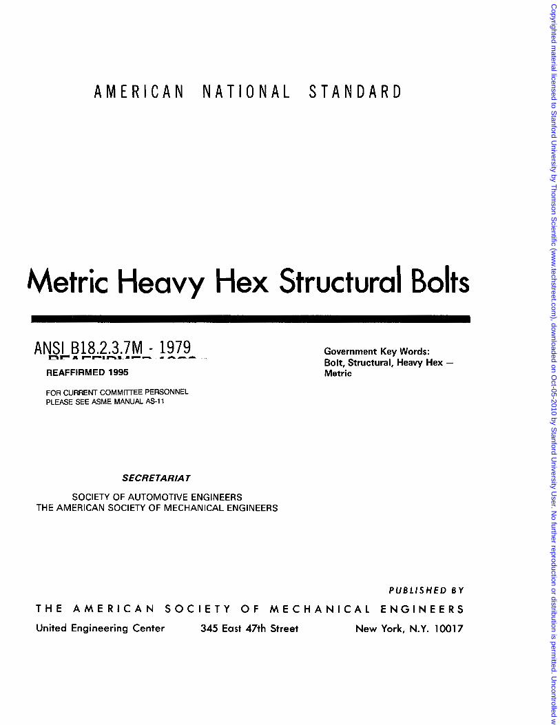
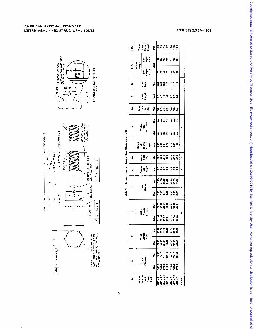
4. Top of Head. The top of head shall be full form and chamfered or rounded. The diameter of the chamfer circle or the start of rounding shall be equal to the maximum width across flats within a toler- ance of minus 15 percent.
manufactured to the requirements of either. 5. Head Height. The head height is the distance, as The following functional characteristics of bolts measured parallel to the axis of the bolt, from the top
are in agreement between this ANSI standard and the of the head to the under head bearing surface. IS0 proposal:
Diameters and thread pitches (see 24) Body diameters Widths across flats Bearing surface diameters Head heights Thread lengths (see 2.3) Thread dimensions Nominal lengths
6. Wrenching Height. The wrenching height is the distance, measured at a corner of the hex, from the plane of the bearing surface to the last plane of full formed hex, i.e., the plane closest to the top of head at which the width across corners of the hex is within its specified limits.
7. Corner Fill. The rounding due to lack of fill at the six comers of the head shall be reasonably uniform.
Copyrighted m
aterial licensed to Stanford U
niversity by Thom
son Scientific (w
ww
.techstreet.com), dow
nloaded on Oct-05-2010 by S
tanford University U
ser. No further reproduction or distribution is perm
itted. Uncontrolled w
hen printed.
AMERICAN NATIONAL STANDARD METRIC HEAVY HEX STRUCTURAL BOLTS ANSI B18.2.3.7M-1979
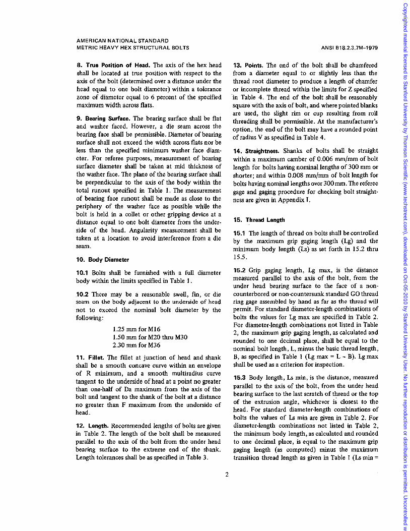
8. True Position of Head. The axis of the hex head shall be located at true position with respect to the axis of the bolt (determined over a distance under the head equal to 'one bolt diameter) within a tolerance zone of diameter equal to 6 percent of the specified maximum width across flats.
9. Bearing Surface. The bearing surface shall be flat and washer faced. However, a die seam across the bearing face shall be permissible. Diameter of bearing surface shall not exceed the width across flats nor be less than the specified minimum washer face diam- eter. For referee purposes, measurement of bearing surface diameter shall be taken at mid thickness of the washer face. The plane of the bearing surface shall be perpendicular to the axis of the body within the total runout specified in Table 1. The measurement of bearing face runout shall be made as close to the periphery of the washer face as possible while the bolt is held in a collet or other gripping device at a distance equal to one bolt diameter from the under- side of the head. Angularity measurement shall be taken at a location to avoid interference from a die seam.
IO. Body Diameter
10.1 Bolts shall be furnished with a full diameter body within the limits specified in Table 1.
10.2 There may be a reasonable swell, fin, or die seam on the body adjacent to the underside of head not to exceed the nominal bolt diameter by the following:
1.25 mm for M16 1 S O mm for M20 thru M30 2.30 mm for M36
11. Fillet. The fillet at junction of head and shank shall be a smooth concave curve within an envelope of R minimum, and a smooth multiradius curve tangent to the underside of head at a point no greater than one-half of Da maximum from the axis of the bolt and tangent to the shank of the bolt at a distance no greater than F maximum from the underside of head.
12. Length. Recommended lengths of bolts are given in Table 2. The length of the bolt shall be measured parallel to the a x i s of the bolt from the under head bearing surface to the extreme end of the shank. Length tolerances shall be as specified in Table 3.
13. Points. The end of the bolt shall be chamfered from a diameter equal to or slightly less than the thread root diameter to produce a length of chamfer or incomplete thread within the limits for Z specified in Table 4. The end of the bolt shall be reasonably square with the a x i s of bolt, and where pointed blanks are used, the slight rim or cup resulting from roll threading shall be permissible. At the manufacturer's option, the end of the bolt may have a rounded point of radius V as specified in Table 4.
14. Straightness. Shanks of bolts shall be straight within a maximum camber of 0.006 mm/mm of bolt length for bolts having nominal lengths of 300 mm or shorter; and within 0.008 mm/mm of bolt length for bolts having nominal lengths over 300 mm. The referee gage and gaging procedure for checking bolt straight- ness are given in Appendix I.
15. Thread Length
15.1 The length of thread on bolts shall be controlled by the maximum grip gaging length (Lg) and the minimum body length (Ls) as set forth in 15.2 thru 15.5.
15.2 Grip gaging length, Lg max, is the distance measured parallel to the axis of the bolt, from the under head bearing surface to the face of a non- counterbored or noncountersunk standard GO thread ring gage assembled by hand as far as the thread will permit. For standard diameter-length combinations of bolts the values for Lg max are specified in Table 2. For diameter-length combinations not listed in Table 2, the maximum grip gaging length, as calculated and rounded to one decimal place, shall be equal to the nominal bolt. length, L, minus the basic thread length, B, as specified in Table 1 (Lg max = L - B). Lg max shall be used as a criterion for inspection.
15.3 Body length, Ls min, is the distance, measured parallel to the axis of the bolt, from the under head bearing surface to the last scratch of thread or the top of the extrusion angle, whichever is closest to the head. For standard diameter-length combinations of bolts the values of Ls min are given in Table 2. For diameter-length combinations not listed in Table 2, the minimum body length, as calculated and rounded to one decimal place, is equal to the maximum grip gaging length (as computed) minus the maximum transition thread length as given in Table 1 (Ls min =
2
Copyrighted m
aterial licensed to Stanford U
niversity by Thom
son Scientific (w
ww
.techstreet.com), dow
nloaded on Oct-05-2010 by S
tanford University U
ser. No further reproduction or distribution is perm
itted. Uncontrolled w
hen printed.
AMERICAN NATIONAL STANDARD METRIC HEAVY HEX STRUCTURAL BOLTS
Lg max - X max). Ls min shall be used as a criterion for inspection. Bolts of nominal lengths which have a calculated Ls min value equal to or less than the length of 2.5 times the thread pitch shall be threaded full length. Bolts which are threaded full length shall have a minimum body length under the head equal to F as specified in Table 1.
15.4 Basic thread length, B, as specified in Table 1 is a reference dimension intended for calculation pur- poses only, and is the distance, measmed parallel to the a x i s of the bolt, from the extreme end of the bolt to the last complete (full form) thread.
15.5 Transition thread length, X max, as specified in Table 1 is a reference dimension intended for calcula- tion purposes only. It includes the length of incom- plete threads and tolerances on grip gaging length and body length. The transition from full thread to in- complete thread shall be smooth and uniform. The major diameter of the incomplete threads shall not exceed the actual major diameter of the complete (full form) threads.
16. Thread Series. Threads shall be metric coarse thread series conforming to dimensions for general purpose external .threads given in ANSI B1.13. The class 6g tolerance shall apply to plain finish (unplated or uncoated) bolts, and to plated or coated bolts be- fore plating or coating.
17. Material and Mechanical Properties. Chemical composition and mechanical requirements of steel bolts shall conform to ASTM A325M or ASTM A490M.
Note These two ASTM standards are under de- velopment. Mechanical properties of A325M bolts are essentially the same as SAE 51199 property class 8.8, and those of A490M essentially the same as SAE J 1 199 property class 10.9.
18. Finish. Unless otherwise specified, screws and bolts shall be supplied with a natural (as processed) finish, unplated or uncoated.
19. Identification Symbols. Steel bolts shall be marked with the grade identification symbols and with the manufacturer's identification symbol. Mini- mum height of property class symbols shall be 4.0
ANSI B18.2.3.7M-1979
mm. Markings shall be located on the top of the head and may be raised or recessed unless otherwise ordered by the purchaser. When raised, markings shall project not less than 0.3 mm above the surface of the head, and total head height (head plus markings) shall not exceed the specified maximum head height plus 0.4 mm.
20. Options. Options, where specified, shall be at the discretion of the manufacturer unless otherwise agreed upon by the manufacturer and the purchaser.
21. Terminology. For definition of terms relating to fasteners or component features thereof used in this standard, refer to American National Standard, Glos- sary of Terms for Mechanical Fasteners, ANSI B18.12.
22. Workmanship. Bolts shall not contain an excess of surface imperfections which might affect their ser- viceability, such as burrs, seams, laps, loose scale and other irregularities.
23. Clearance Holes. The recommended sizes of clearance holes in material to be assembled using heavy hex structural bolts are the normal series given in Appendix 11.
24. Designation
24.1 Heavy hex structural bolts shall be designated by the following data preferably in the sequence shown: product name, 'nominal diameter and thread pitch, nominal length, steel property class, and protective coating, if required.
Note
It is common practice in IS0 standards to omit thread pitch from the product size designation when screw threads are the metric coarse thread series, e.g., M20 is M20 x 2.5..
Examples: Heavy hex structural bolt, M22 x 2.5 x 160, ASTM
Heavy hex structural bolt, M24 x 3 x 80, ASTM A325M, zinc galvanized
A490M.
24.2 The Government part numbering system for metric heavy hex structural bolts is given in Appendix 111.
3
Copyrighted m
aterial licensed to Stanford U
niversity by Thom
son Scientific (w
ww
.techstreet.com), dow
nloaded on Oct-05-2010 by S
tanford University U
ser. No further reproduction or distribution is perm
itted. Uncontrolled w
hen printed.
AMERICAN NATIONAL STANDARD METRIC HEAVY HEX STRUCTURAL BOLTS ANSI 818.2.3.7M-1979
25. Referenced Standards tained from the Society of Automotive Engineers, Inc., 400 Commonwealth Drive, Warrendale, Penn-
Copies of referenced ASTM standards may be ob- sylvania 15096. tained from the American Society for Testing and Materials, 1916 Race Street, Philadelphia, Pennsyl- Copies of referenced Iso standards may be ob- vania 19103. tained from the American National Standards Insti-
Copies of referenced SAE standards may be ob- tute, 1430 Broadway, New York, N.Y. 10018.
4
Copyrighted m
aterial licensed to Stanford U
niversity by Thom
son Scientific (w
ww
.techstreet.com), dow
nloaded on Oct-05-2010 by S
tanford University U
ser. No further reproduction or distribution is perm
itted. Uncontrolled w
hen printed.
NOTE
12
p-,
PRO
PER
TY C
LASS
AN
D
MA
NU
t E
I FILLET \ ’
INC
OM
PLET
E TH
REA
D
w-\-
150-
303
SEE
DETA
IL
SEE NO
TE
155
FAC
TUR
ER’S
iDEN
TlFl
CAT
lON
TO
APP
EAR
ON
TO
P O
F H
EAD
SE
E NO
TE 1
9
NOTE
15
4 x”
OPT
IONA
L PO
INT
SEE
NOTE
13
CONS
TRUC
TIO
N
ILL‘’
SHA
DED
SEC
TIO
N RE
PRES
ENTS
ENV
ELO
PE
OR
FILL
ET L
IMIT
S
ENLA
RG
ED D
ETAI
L O
F FI
LLET
SE
E NO
TE 1
1
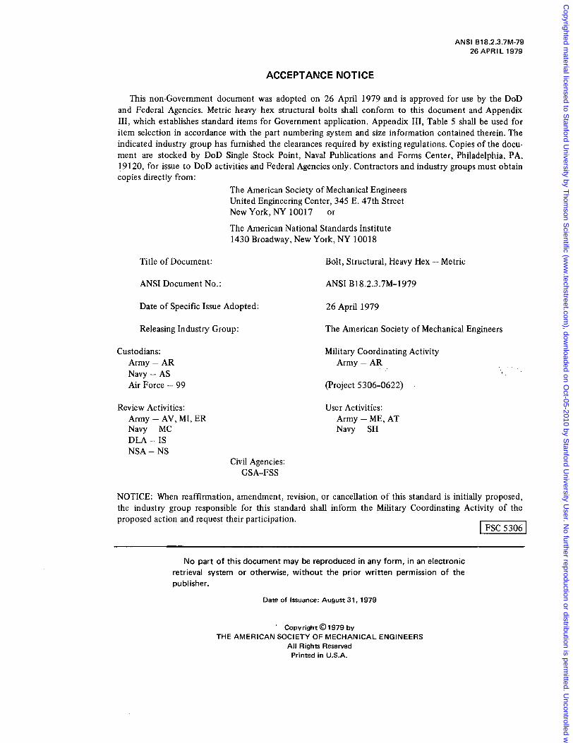
Tabl
e 1
Dim
ensi
ons o
f Hea
vy H
ex S
truct
ural
Bol
ts
D
X (R
ef1
E (R
ef1
R F
Da
C
Dw
K,
K
E S
tk
Nom
inal
B
olt D
ia
MY
an
d D
imn
sr
Th
ld
Pitc
h
Run
out
Wid
th
Thic
knar
Su
rfacs
Di
m
Haig
ht
Co
rnn
Fl
at,
FKB
Be
arin
g Fa
ce
ing
Acr
oss
Acm
u
Was
her
of
Was
her
Wnn
ch.
Wid
th
Thre
ad
Hwad
Hw
ipht
Fille
t
Radi
us
Leng
th
ition
Fi
llet
Fille
t Tr
ans-
Tr
anr-
La
mat
h
Le
~th
l Lw
npth
r Th
read
D
is
Bol
t
Lanp
th
>loo
<loo
ition
&
It ~
FIM
Max
7.5
45
41
38
1.0
4.0
26.4
0.
4 0.
8 0.
70
38.0
9.
9 14
.10
15.9
0 45
.20
47.3
4 40
.00
41.0
0 23
.16
24.8
4 M
24x3
7.5
43
36
0.8
4.0
24.4
0.
4 0.
8 0.
63
33.3
9.
2 13
.10
14.9
0 39
.55
41.5
7 35
.00
36.0
0 21
.16
22.8
4 M
22x
2.5
6.0
38
31
0.8
4.0
22.4
0.
4 0.
8 0.
59
31.4
8.
1 11
.60
13.4
0 37
.29
39.2
6 33
.00
34.00
19.1
6 20
.84
MZO
x2.5
0.
6 3.
0 18
.2
0.4
0.8
0.48
24
.9
6.5
9.25
10
.75
29.5
6 31
.18
26.1
6 27
.00
15.3
0 16
.70
M16
x 2
Max
Ba
ric
Min
M
ax
Max
M
in
Max
M
ax
Min
M
in
Min
M
ax
Min
M
ax
Min
M
ax
Min
48
9.0
M27
x 3
27.8
4 26
.16
46.0
0 45
.00
53.1
2 50
.85
17.9
0 16
.10
11.3
6.
0 33
.4
0.4
0.8
0.85
46
.5
12.4
17
.65
19.7
5 55
.37
57.7
4 49
.00
50.0
0 29
.16
30.8
4 M
30x
3.5
1.2
5.0
30.4
0.
4 0.
8 0.
77
42.8
44
51
9.
0
M36
x4
37.0
0 35
.00
60.0
0 58
.80
69.2
8 66
.44
23.5
5 21
.45
15.0
55
.9
1.01
11
9 9
9 6
5 6.
7 10
Se
e N
otes
12.0
63
10
.5
56
56
1.5
49
1.2
6.0
39.4
0.
4 0.
8 I
Copyrighted m
aterial licensed to Stanford U
niversity by Thom
son Scientific (w
ww
.techstreet.com), dow
nloaded on Oct-05-2010 by S
tanford University U
ser. No further reproduction or distribution is perm
itted. Uncontrolled w
hen printed.
AMERICAN NATIONAL STANDARD METRIC HEAVY HEX STRUCTURAL BOLTS ANSI B18.2.3.7M-1979
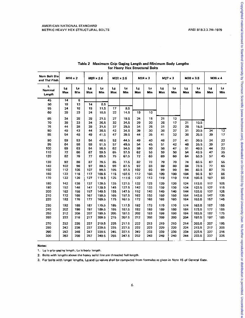
Table 2 Maximum Grip Gaging Length and Minimum Body Lengths for Heavy Hex Structural Bolts
I Nom Bolt Dia and Thd Pitch M16 x 2 ,
L Nominal Lg I Max Length
I 45 1 14 50 55 60
65 70 75 80 85
90 95
100 110 120
130 140 150 160 170
180 190 200 210 220
230 240 250 260
2 70 280 290 300
19 24 29
34 39 44 49 54
59 64 69 72 82
92 102 112 122 132
142 152 162 172 182
192 202 212 222
232 242 252 262
- Ls
Min
8 13 18 23
28 33 38 43 48
53 58 63 66 76
86 96
106 116 126
136 146 156 166 176
186 196 206 216
226 236 246 256
-
-
M20 x 2.5
Lg Min Max Ls
14
16.5 24 11.5 19 6.5
29 21.5 34 26.5 39 31.5 44
41.5 49 36.5
54 46.5 59 51.5 64 56.5 67 59.5 77 69.5
87 79.5 97 89.5
107 99.5 117 109.5 127 119.5
137 129.5 147 139.5 157 149.5 167 159.5 177 169.5
187 179.5 197 189.5 207 199.5 217 209.5
227 219.5 237 229.5 247 239.5 257 249.5
M22 x 2.5 -
Lg Max - -
17 22
27 32 37 42 47
52 57 62 65 75
85 95
105 115 125
135 145 155 165 175
185 195 205 215
225 235 245 255 -
Ls Min - -
9.5 14.5
19.5 24.5 29.5 34.5 39.5
44.5 49.5 54.5 57.5 67.5
77.5 87.5 97.5
107.5 117.5
127.5 137.5 147.5 157.5 167.5
177.5 187.5 197.5 207.5
217.5 227.5 237.5 247.5
M24 x 3 M27 x 3 T -
Lg Max - -
19
24 29 34 39 44
49 54 59 62 72
82 92
102 112 122
132 142 152 162 172
182 192 202 21 2
222 232 242 252 -
Notes: 1. Lg is grip gaging length; L s is body length. 2. Bolts with lengths above the heavy solid line are threaded full length.
Ls Max Min Lg
10
15 21 20
41 35 36 30 31 25 26
40 46 45 51 50 56 53 59 63 69
73 79 83 89 93 99
103 109 113 119
123 129 133 139 143 149 153 159 163 169
173 179 183 189 193 199 203 209
213 219 223 229 233 239 243 249
Ls Min
- 12 17 22 27 32
37 42 47 50 60
70 80 90
100 110
120 130 140 150 160
170 180 190 200
21 0 220 230 240
M30 x 3.5
Lg Max
- 21 26 31 36
41 46 51 54 64
74 84 94
104 114
124 134 144 154 164
174 184 194 204
214 224 234 244
- Ls
Min
- 10.5 16.5 20.5 25.5
30.5 35.5 40.5 43.5 63.5
63.5 73.5 83.5 93.5
103.5
113.5 123.5 133.5 143.5 153.5
163.5 173.5 183.5 193.5
203.5 21 3.5 223.5 233.5
T M36 x 4
Lg Max
- 24 29
34 39 44 47 57
67 77 87 97
107
117 127 137 147 157
167 177 187 197
207 21 7 227 237
- Ls
Min -
- 12 17
22 27 32 35 45
55 65 75 85 95
105 115 125 135 145
155 165 175 185
195 205 21 5 225 -
3. For bolts with longer lengths, Lg and Ls values shall be computed from formulas as given in Note 15 of General Data.
6
Copyrighted m
aterial licensed to Stanford U
niversity by Thom
son Scientific (w
ww
.techstreet.com), dow
nloaded on Oct-05-2010 by S
tanford University U
ser. No further reproduction or distribution is perm
itted. Uncontrolled w
hen printed.
AMERICAN NATIONAL STANDARD METRIC HEAVY HEX STRUCTURAL BOLTS
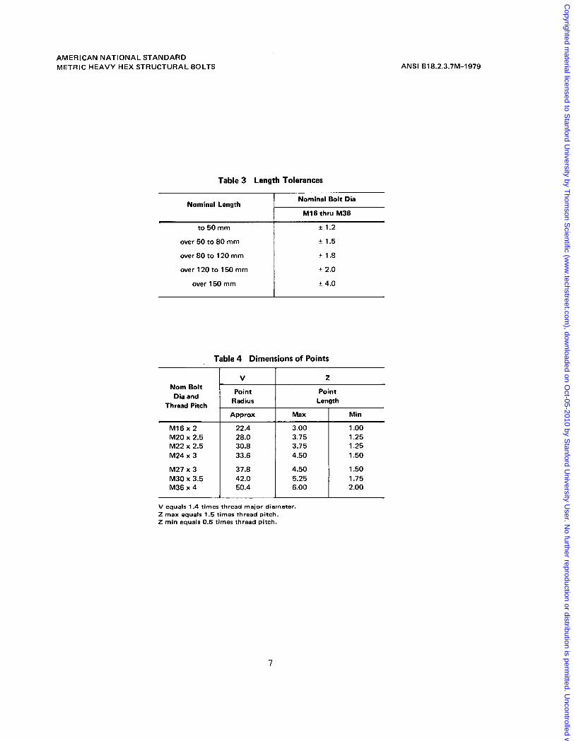
Table 3 Length Tolerances
ANSI 618.2.3.7M-1979
Nominal Length Nominal Bolt Dia
to 50 mm
over 50 to 80 mm
over 80 to 120 mm
over 120 to 150 mm
over 150 mm
f 1.2
f 1.5
f 1.8
f 2.0
f 4.0
Table 4 Dimensions of Points
Nom Bolt Dia and
Thread Pitch
M16x 2 M20 x 2.5 M22 x 2.5 M24 x 3
M27 x 3 M30 x 3.5 M36 x 4
V
Point Radius
Approx
22.4 28.0 30.8 33.6
37.8 42.0 50.4
z Point
Length
Max Min
3.00 1 .oo 3.75 1.25 3.75 1.25 4.50 1.50
4.50 1.50 5.25 1.75 6.00 2.00
V equals 1.4 times thread major diameter. Z max equals 1.5 times thread pitch. Z min equals 0.5 times thread pitch.
7
Copyrighted m
aterial licensed to Stanford U
niversity by Thom
son Scientific (w
ww
.techstreet.com), dow
nloaded on Oct-05-2010 by S
tanford University U
ser. No further reproduction or distribution is perm
itted. Uncontrolled w
hen printed.
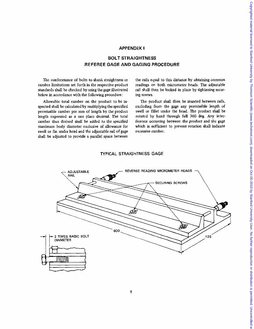
APPENDIX I
BOLT STRAIGHTNESS REFEREE GAGE AND GAGING PROCEDURE
The conformance of bolts to shank straightness or camber limitations set forth in the respective product standards shall be checked by using the gage illustrated below in accordance with the following procedure:
Allowable total camber on the product to be in- spected shall be calculated by multiplying the specified permissible camber per mm of length by the product length expressed as a one place decimal. The total camber thus derived shall be added to the specified maximum body diameter exclusive of allowance for swell or fin under head and the adjustable rail of gage shall be adjusted to provide a parallel space between
the rails equal to this distance by obtaining common readings on both micrometer heads. The adjustable rail shall then be locked in place by tightening secur- ing screws.
The product shall then be inserted between rails, excluding from the gage any permissible length of swell or fillet under the head. The product shall be rotated by hand through full 360 deg. Any inter- ference occurring between the product and the gage which is sufficient to prevent rotation shall indicate excessive camber.
TYPICAL STRAIGHTNESS GAGE
REVERSE READING MICROMETER HEADS
SECURING SCREWS
2 TIMES BASIC BOLT
8
Copyrighted m
aterial licensed to Stanford U
niversity by Thom
son Scientific (w
ww
.techstreet.com), dow
nloaded on Oct-05-2010 by S
tanford University U
ser. No further reproduction or distribution is perm
itted. Uncontrolled w
hen printed.
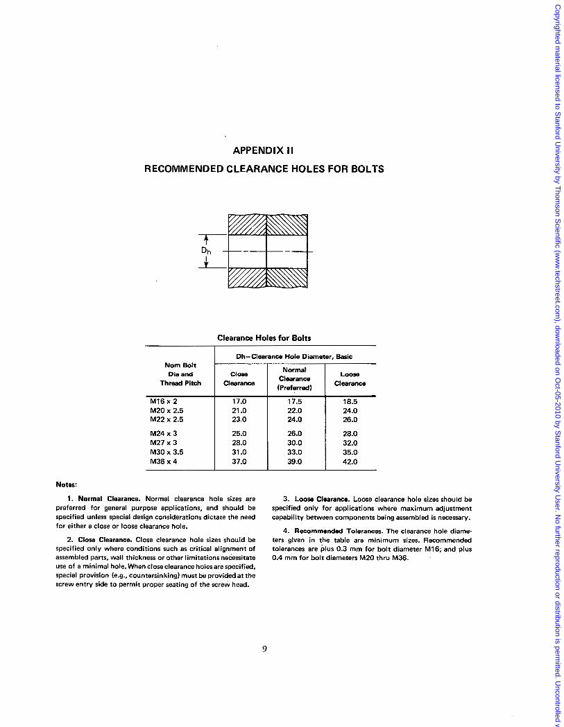
APPENDIX II
RECOMMENDED CLEARANCE HOLES FOR BOLTS
Clearance Holes for Bolts
Dh-Clearance Hole Diameter, Basic
Normal Clearance (Preferred)
Nom Bolt Dia and
Clearance Thread Pitch Close Loose
Clearance
MI6 x 2
26.0 24.0 23.0 M22 x 2.5 24.0 22.0 21 .o M20 x 2.5 18.5 17.5 17.0
M24 x 3 25.0 26.0 28.0 M27 x 3
42.0 39.0 37.0 M36 x 4 35.0 33.0 31 .O M30 x 3.5 32.0 30.0 28.0
Notes:
1 . Normal Clearance. Normal clearance hole sizes are 3. Loose Clearance. Loose clearance hole sizes should be preferred for general purpose applications, and should be specified only for applications where maximum adjustment specified unless special design considerations dictate the need capability between components being assembled is necessary. for either a close or loose clearance hole.
4. Recommended Tolerances. The clearance hole diame- 2. Close Clearance. Close clearance hole sizes should be ters given in the table are minimum sizes. Recommended
specified only where conditions such as critical alignment o f tolerances are plus 0.3 mm for bol t diameter M16; and plus assembled parts, wall thickness or other limitations necessitate 0.4 mm for bol t diameters M20 thru M36. use of a minimal hole. When close clearance holesare specified, special provision (e.g., countersinking) must be provided at the screw entry side to permit proper seating of the screw head.
9
Copyrighted m
aterial licensed to Stanford U
niversity by Thom
son Scientific (w
ww
.techstreet.com), dow
nloaded on Oct-05-2010 by S
tanford University U
ser. No further reproduction or distribution is perm
itted. Uncontrolled w
hen printed.
APPENDIX I I I
Government Standard Items and Part Numbering System
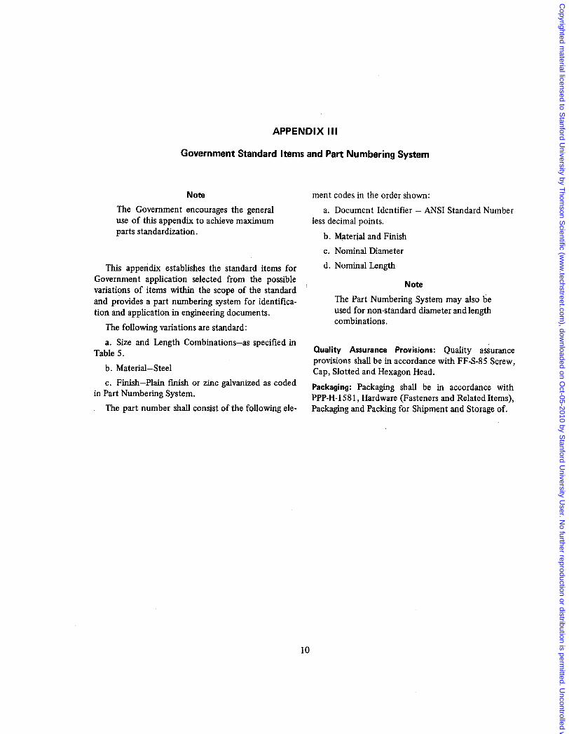
Note The Government encourages the general use of this appendix to achieve maximum parts standardization.
This appendix establishes the standard items for Government application selected from the possible variations of items within the scope of the standard and provides a part numbering system for identifica- tion and application in engineering documents.
The following variations are standard: a. Size and Length Combinations-as specified in
Table 5. b. Material-Steel c. Finish-Plain finish or zinc galvanized as coded
in Part Numbering System. The part number shall consist of the following ele-
ment codes in the order shown: a. Document Identifier - ANSI Standard Number
less decimal points. b. Material and Finish c. Nominal Diameter d. Nominal Length
Note
The Part Numbering System may also be used for non-standard diameter and length combinations.
Quality Assurance Provisions: Quality assurance provisions shall be in accordance with FF-S-85 Screw, Cap, Slot.ted and Hexagon Head. Packaging: Packaging shall be in accordance with PPP-H-1581, Hardware (Fasteners and Related Items), Packaging and Packing for Shipment and Storage of.
10
Copyrighted m
aterial licensed to Stanford U
niversity by Thom
son Scientific (w
ww
.techstreet.com), dow
nloaded on Oct-05-2010 by S
tanford University U
ser. No further reproduction or distribution is perm
itted. Uncontrolled w
hen printed.
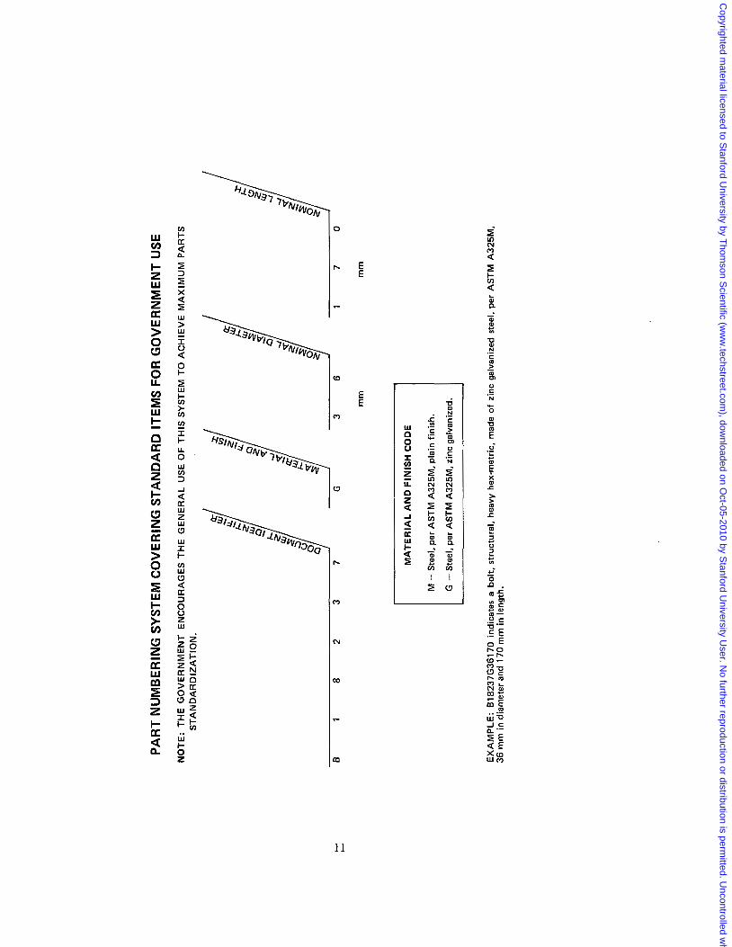
PART
NUM
BERI
NG S
YSTE
M C
OVE
RING
STA
NDAR
D IT
EMS
FOR
GO
VER
NM
ENT
USE
NO
TE:
THE
GO
VER
NM
ENT
ENC
OU
RA
GES
TH
E G
ENER
AL
USE OF T
HIS
SYS
TEM
TO
AC
HIE
VE M
AXI
MU
M P
AR
TS
STA
ND
AR
DIZ
ATI
ON
.
c
L
mm
m
m
M - S
teel
, per
AST
M A
325M
, pla
in fi
nish
.
G - St
eel,
per
AST
M A
325M
. zin
c ga
lvan
ized
.
EXA
MPL
E: 8
1823
7G36
170
indi
cate
s a bo
lt, st
ruct
ural
, hea
vy he
x-m
etric
, mad
e of
zin
c gal
vani
zed
stee
l, pe
r A
STM
A32
5M.
36 m
m in
dia
met
er a
nd 1
70 m
m in
leng
th.
Copyrighted m
aterial licensed to Stanford U
niversity by Thom
son Scientific (w
ww
.techstreet.com), dow
nloaded on Oct-05-2010 by S
tanford University U
ser. No further reproduction or distribution is perm
itted. Uncontrolled w
hen printed.
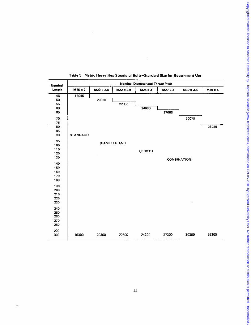
Table 5 Metric Heavy Hex Structural Bolts-Standard Size for ,Government Use
Nominal Diameter and Thread Pitch Nominal Length
45 50 55 60 65
70 75 80 85 90
95 100 110 120 130
140 150 160 170 180
190 200 210 220 230
240 250 260 270 280
290 300
M16x2 1 M20x2.5 I M22x2.5 I M24x3 I M27x3 I M30x3.5 I M36x4 1 1 1 1 1 1
16045 I 20050 I
22055 ~~----L 24060 27065
30070
36080
STANDARD
DIAMETER AND
LENGTH
COMBINATION
16300 20300 22300 24300 27300 30300 36300
12
.
Copyrighted m
aterial licensed to Stanford U
niversity by Thom
son Scientific (w
ww
.techstreet.com), dow
nloaded on Oct-05-2010 by S
tanford University U
ser. No further reproduction or distribution is perm
itted. Uncontrolled w
hen printed.
Copyrighted m
aterial licensed to Stanford U
niversity by Thom
son Scientific (w
ww
.techstreet.com), dow
nloaded on Oct-05-2010 by S
tanford University U
ser. No further reproduction or distribution is perm
itted. Uncontrolled w
hen printed.