army tm 9-6115-672-14 air force to 35c2-3-444-32 marine ...
13
ARMY TM 9-6115-672-14 AIR FORCE TO 35C2-3-444-32 MARINE CORPS TM 09244A/09245A-14 TECHNICAL MANUAL OPERATOR, UNIT, DIRECT SUPPORT AND GENERAL SUPPORT MAINTENANCE MANUAL GENERATOR SET, SKID MOUNTED, TACTICAL QUIET 60 KW, 50/60 AND 400 HZ MEP-806B (50/60 HZ) (NSN 6115-01-462-0291) EIC: GGW MEP-816B (400 HZ) (NSN 6115-01-462-0292) EIC: GGX DISTRIBUTION STATEMENT A: Approved for public release; distribution is unlimited. DEPARTMENTS OF THE ARMY, AND THE AIR FORCE AND HEADQUARTERS, MARINE CORPS 1 July 2000 PCN 182 092443 00 HOW TO USE THIS MANUAL PAGE ix EQUIPMENT DESCRIPTION AND DATA PAGE 1-4 PRINCIPLES OF OPERATION PAGE 1-16 CONTROLS AND INDICATORS PAGE 2-1 OPERATOR PMCS PAGE 2-14 OPERATOR TROUBLESHOOTING PAGE 3-1 OPERATOR MAINTENANCE PAGE 3-18 UNIT TROUBLESHOOTING PAGE 4-10 UNIT MAINTENANCE PAGE 4-49 DIRECT SUPPORT TROUBLESHOOTING PAGE 5-2 DIRECT SUPPORT MAINTENANCE PAGE 5-14 GENERAL SUPPORT MAINTENANCE PAGE 6-1
-
Upload
khangminh22 -
Category
Documents
-
view
1 -
download
0
Transcript of army tm 9-6115-672-14 air force to 35c2-3-444-32 marine ...
ARMY TM 9-6115-672-14 AIR FORCE TO 35C2-3-444-32
MARINE CORPS TM 09244A/09245A-14
TECHNICAL MANUAL OPERATOR, UNIT, DIRECT SUPPORT
AND GENERAL SUPPORT MAINTENANCE MANUAL
GENERATOR SET, SKID MOUNTED, TACTICAL QUIET
60 KW, 50/60 AND 400 HZ MEP-806B (50/60 HZ) (NSN 6115-01-462-0291) EIC: GGW MEP-816B (400 HZ) (NSN 6115-01-462-0292) EIC: GGX
DISTRIBUTION STATEMENT A: Approved for public release; distribution is unlimited.
DEPARTMENTS OF THE ARMY, AND THE AIR FORCE AND HEADQUARTERS, MARINE CORPS
1 July 2000 PCN 182 092443 00
HOW TO USE THIS MANUAL PAGE ix EQUIPMENT DESCRIPTION AND DATA PAGE 1-4 PRINCIPLES OF OPERATION
PAGE 1-16 CONTROLS AND INDICATORS PAGE 2-1 OPERATOR PMCS PAGE 2-14 OPERATOR TROUBLESHOOTING PAGE 3-1 OPERATOR MAINTENANCE PAGE 3-18 UNIT TROUBLESHOOTING PAGE 4-10 UNIT MAINTENANCE PAGE 4-49 DIRECT SUPPORT TROUBLESHOOTING PAGE 5-2 DIRECT SUPPORT MAINTENANCE PAGE 5-14 GENERAL SUPPORT MAINTENANCE PAGE 6-1
ARMY TM 9-6115-672-14 AIR FORCE TO 35C2-3-444-32
MARINE CORPS TM 09244A/09245A-14
i
OPERATOR, UNIT, DIRECT SUPPORT AND GENERAL SUPPORT MAINTENANCE MANUAL
FOR GENERATOR, SKID MOUNTED, TACTICAL QUIET,
60 KW, 50/60 AND 400 HZ
MEP-806B (50/60 HZ) (NSN 6115-01-462-0291) (EIC:GGW) MEP-816B (400 HZ) (NSN 6115-01-462-0292) (EIC:GGX)
REPORTING ERRORS AND RECOMMENDING IMPROVEMENTS You can help improve this manual. If you find any mistakes, or if you know of a way to improve the procedures, please let us know. Mail your letter, DA Form 2028 (Recommended Changes to Publications and Blank Forms) or DA Form 2028-2 located in back of this manual directly to: Commander, US Army Communications-Electronics Command and Fort Monmouth, ATTN: AMSEL-LC-LEO-D-CS-CFO, Fort Monmouth, New Jersey 07703-5006. The fax number is 732-532-1413, DSN 992-1413. You may also e-mail your recommendations to [email protected] For Air Force, submit AFTO Form 22 (Technical Order System Publication Improvement Report and Reply) in accordance with paragraph 6-5, Section VI, TO 00-5-1. Forward direct to prime ALC/MST. Marine Corps units, submit NAVMC 10772 (Recommended Changes to Technical Publications) to: Commanding General, Marine Corps Logistics Base (Code 850), Albany, Georgia 31704-5000. In any case, we will send you a reply.
Technical Manual No. 9-6115-672-14 Technical Order No. 35C2-3-444-32 Technical Manual No. 09244A/09245A-14
DEPARTMENTS OF THE ARMY AND THE AIR FORCE, AND
HEADQUARTERS, MARINE CORPS WASHINGTON, DC, 1 July 2000
ARMY TM 9-6115-672-14 AIR FORCE TO 35C2-3-444-32 MARINE CORPS TM 09244A/09245A-14
ii
TABLE OF CONTENTS Chapter\ Section Page How To Use This Manual.............................................................................................................................................ix Chapter 1 Introduction Section I General Information.........................................................................................................1-1 1.1 Scope ...............................................................................................................................1-1 1.2 Limited Applicability.......................................................................................................1-1 1.3 Maintenance Forms and Records .....................................................................................1-1 1.4 Reporting of Errors ..........................................................................................................1-1 1.5 Preparation for Storage or Shipment................................................................................1-3 1.6 Quality Assurance ............................................................................................................1-3 1.7 Reporting Equipment Improvement Recommendation (EIR) ..........................................1-3 1.8 List of Abbreviations .......................................................................................................1-3 1.9 Levels of Maintenance .....................................................................................................1-4 1.10 Corrosion Prevention Control ..........................................................................................1-4 1.11 Destruction of Army Materiel to Prevent Enemy Use......................................................1-4 Section II Equipment Description and Data .....................................................................................1-4 1.12 General.............................................................................................................................1-4 1.13 Tabulated/Illustrated Data................................................................................................1-4 1.14 Differences Between Models .........................................................................................1-15 Section III Principles of Operation ..................................................................................................1-16 1.15 Introduction....................................................................................................................1-16 1.16 Principles of Operation ..................................................................................................1-16 1.17 Location and Description of Major Components...........................................................1-35 Chapter 2 Operating Instructions Section I Description and Use of Operator Controls and Indicators ...............................................2-1 2.1 General.............................................................................................................................2-1 2.2 DCS Controls and Indicators ...........................................................................................2-1 2.3 Computer Interface Module (CIM) Display Screen Controls and Indicators...................2-4 2.4 Diagnostic Controls and Indicators..................................................................................2-8 Section II Preventative Maintenance Checks and Services (PMCS) ..............................................2-14 2.5 General...........................................................................................................................2-14 2.6 PMCS Procedures..........................................................................................................2-14 Section III Operation Under Usual Conditions................................................................................2-21 2.7 General...........................................................................................................................2-21 2.8 Generator Set Installation ..............................................................................................2-21 2.9 Assembly and Preparation for Use.................................................................................2-24 2.10 Initial Adjustments, Checks, and Self-Test ....................................................................2-27 2.11 Operating Procedure ......................................................................................................2-30 2.12 Parallel Unit Operation (Load Sharing) .........................................................................2-33 2.13 Remote Operation ..........................................................................................................2-36 2.14 Preparation for Movement .............................................................................................2-39 Section IV Operation Under Unusual Conditions............................................................................2-41 2.15 Operation in Extreme Cold Weather Below -25° F (-31° C) .........................................2-41 2.16 Operation in Extreme Heat Above 120° F (48.8° C) .....................................................2-42 2.17 Operation in Dusty or Sandy Areas................................................................................2-42 2.18 Operation Under Rainy or Humid Conditions ...............................................................2-43 2.19 Operation in Salt Water Areas .......................................................................................2-43 2.20 Operation at High Altitudes ...........................................................................................2-44 2.21 NATO SLAVE RECEPTACLE Start Operation ...........................................................2-44
ARMY TM 9-6115-672-14 AIR FORCE TO 35C2-3-444-32
MARINE CORPS TM 09244A/09245A-14
iii
TABLE OF CONTENTS (continued)
Chapter\ Section Page 2.22 Emergency Stopping......................................................................................................2-44 2.23 Operation Using Battle Short Switch.............................................................................2-44 2.24 Nuclear, Biological, and Chemical (NBC) Decontamination Procedures......................2-45 2.25 Operation While Contaminated .....................................................................................2-46 2.26 Operation in a High Altitude Electromagnetic Pulse (HAEMP) Environment ..............2-46 Chapter 3 Operator Maintenance Instructions Section I Lubrication Procedures ....................................................................................................3-1 3.1 Operator Lubrication Instructions....................................................................................3-1 Section II Troubleshooting...............................................................................................................3-1 3.2 General.............................................................................................................................3-1 Symptom Index................................................................................................................3-1 Section III Operator Maintenance Procedures.................................................................................3-18 3.3 Generator Set Inspection and Service ............................................................................3-18 Chapter 4 Unit Maintenance Instructions
Section I Inspecting and Servicing the Equipment..........................................................................4-1 4.1 Inspecting and Servicing the Equipment..........................................................................4-1 Section II Repair Parts; Tools; Test, Measurement and Diagnostic Equipment (TMDE); and Support Equipment .................................................................4-6 4.2 Introduction......................................................................................................................4-6
Section III Lubrication Procedures ....................................................................................................4-6 4.3 Unit Lubrication Instructions ...........................................................................................4-6 Section IV Unit Preventive Maintenance Checks and Services (PMCS)...........................................4-7 4.4 PMCS Procedures............................................................................................................4-7 Section V Troubleshooting.............................................................................................................4-10 4.5 General...........................................................................................................................4-10 Symptom Index..............................................................................................................4-10 Section VI Unit Maintenance Procedures ........................................................................................4-49 4.6 Maintenance of DC Electrical System ...........................................................................4-49 4.7 Maintenance of Housing ................................................................................................4-56 4.8 Maintenance of DCS Control Box Assembly ................................................................4-78 4.9 Maintenance of Air Intake and Exhaust System ..........................................................4-142 4.10 Maintenance of Engine Cooling System ......................................................................4-151 4.11 Maintenance of Fuel System........................................................................................4-170 4.12 Maintenance of Output Box Assembly ........................................................................4-184 4.13 Maintenance of Engine Accessories ............................................................................4-195 4.14 Maintenance of Lubrication System.............................................................................4-205 Section VII Preparation for Shipment and Storage .........................................................................4-206 4.15 Preparation for Shipment and Storage .........................................................................4-206
4.16 CIM Configuration Switch...........................................................................................4-208 Chapter 5 Direct Support Maintenance Instructions
Section I Repair Parts; Tools; Test, Measurement and Diagnostic Equipment (TMDE); and Support Equipment........................................................................................................................5-1
5.1 Introduction......................................................................................................................5-1 Section II Lubrication Procedures ....................................................................................................5-1 5.2 Direct Support Lubrication Instructions...........................................................................5-1
ARMY TM 9-6115-672-14 AIR FORCE TO 35C2-3-444-32 MARINE CORPS TM 09244A/09245A-14
iv
TABLE OF CONTENTS (continued)
Chapter\ Section Page Section III Troubleshooting...............................................................................................................5-2 5.3 General.............................................................................................................................5-2 Symptom Index................................................................................................................5-2 Section IV Direct Support Maintenance Procedures........................................................................5-14 5.4 Removal and Installation of Major Components ...........................................................5-14 5.5 Maintenance of DCS Control Box Assembly ................................................................5-22 5.6 Maintenance of Cooling System ....................................................................................5-24 5.7 Maintenance of Fuel System..........................................................................................5-25 5.8 Maintenance of Output Box Assembly ..........................................................................5-28 5.9 Maintenance of Engine Accessories ..............................................................................5-41 5.10 Maintenance of Generator Assembly.............................................................................5-43 5.11 Maintenance of Skid Base .............................................................................................5-59 Chapter 6 General Support Maintenance Instructions ......................................................................6-1 Appendix A References.......................................................................................................................A-1 Appendix B Maintenance Allocation Chart (MAC) Section I Introduction.....................................................................................................................B-1 Section II Maintenance Allocation Chart (MAC)............................................................................B-4 Section III Tools and Test Equipment for MEP-806B and 816B ...................................................B-13 Section IV Remarks ........................................................................................................................B-13 Appendix C Components of End Item (COEI) and Basic Issue Items (BII) List
Section I Introduction.....................................................................................................................C-1 Section II Components of End Item ................................................................................................C-1 Section III Basic Issue Items ............................................................................................................C-2 Appendix D Additional Authorization List (AAL) Section I Introduction.....................................................................................................................D-1 Section II Additional Authorization List .........................................................................................D-1 Appendix E Expendable and Durable Items List Section I Introduction..................................................................................................................... E-1 Section II Expendable and Durable Items List ................................................................................ E-1 Appendix F Operator’s Lubrication Instructions ................................................................................ F-1 Appendix G Illustrated List of Manufactured Items............................................................................G-1 Appendix H Torque Limits Section I Introduction.....................................................................................................................H-1 Section II Torque Limits .................................................................................................................H-1 Appendix I Mandatory Replacement Parts Section I Introduction...................................................................................................................... I-1 Section II Mandatory Replacement Parts ......................................................................................... I-1
ARMY TM 9-6115-672-14 AIR FORCE TO 35C2-3-444-32
MARINE CORPS TM 09244A/09245A-14
v
TABLE OF CONTENTS (continued) Chapter\ Section Page Index....................................................................................................................................................................Index-1 Fold-outs Schematic ................................................................................................................................................. FO-1 Wiring Diagram........................................................................................................................................ FO-3
LIST OF ILLUSTRATIONS Figure Page 1-1 60 Kw Tactical Quiet Generator Set.............................................................................................................1-2 1-2 Locations of Data Plates and Access Doors (Front and Right Side).............................................................1-7 1-3 Locations of Data Plates and Access Doors (Rear and Left Side)................................................................1-8 1-4 Operating Instruction Plate, MEP-806B.......................................................................................................1-9 1-5 Operating Instruction Plate, MEP-816B.....................................................................................................1-10 1-6 Identification Plate, MEP-806B and MEP-816B .......................................................................................1-11 1-7 Set Rating Identification Plate, MEP-806B and MEP-816B......................................................................1-11 1-8 Voltage Connection Caution Plate..............................................................................................................1-12 1-9 Grounding Stud Plate .................................................................................................................................1-12 1-10 NATO SLAVE RECEPTACLE Plate ........................................................................................................1-12 1-11 PARALLELING RECEPTACLE Plate......................................................................................................1-12 1-12 CONVENIENCE RECEPTACLE Plate, MEP-806B and MEP-816B.......................................................1-12 1-13 EXTERNAL FUEL SUPPLY Plate ...........................................................................................................1-12 1-14 Battery Connection Instruction Plate..........................................................................................................1-13 1-15 Lifting and Tiedown Diagram Plate ...........................................................................................................1-13 1-16 FUEL SYSTEM DIAGRAM Plate ............................................................................................................1-14 1-17 Generator Identification Plate (located on generator), MEP-806B and MEP-816B...................................1-14 1-18 COMMUNICATION PORT......................................................................................................................1-14 1-19 Fault System Flow Diagram .......................................................................................................................1-18 1-20 Governor Control System Flow Diagram ...................................................................................................1-19 1-21 Voltage Regulation System Flow Diagram.................................................................................................1-21 1-22 Fuel System Flow Diagram ........................................................................................................................1-22 1-23 Generator Set Cooling System Flow Diagram............................................................................................1-24 1-24 Engine Cooling System Flow Diagram.......................................................................................................1-25 1-25 Lubrication System Flow Diagram.............................................................................................................1-26 1-26 Engine Air Intake and Exhaust System Flow Diagram...............................................................................1-28 1-27 Output Supply System Flow Diagram ........................................................................................................1-30 1-28 Brushless Generator Schematic ..................................................................................................................1-31 1-29 Engine Starting System Flow Diagram.......................................................................................................1-33 1-30 60 kW Generator Set Components .............................................................................................................1-36 2-1 DCS Controls and Indicators........................................................................................................................2-2 2-2 CIM Display Screen Controls and Indicators ..............................................................................................2-5 2-3 Diagnostic Controls and Indicators ..............................................................................................................2-9 2-4 Base Mounting Measurements ...................................................................................................................2-22 2-5 Minimum Enclosure Clearance Measurements ..........................................................................................2-23 2-6 Grounding Connections..............................................................................................................................2-25 2-7 Installation of Load Cables.........................................................................................................................2-27 2-8 Generator Set Controls ...............................................................................................................................2-28 2-9 CIM Display Screen Controls and Indicators ............................................................................................2-32 2-10 Parallel Operation Setup.............................................................................................................................2-34 2-11 Remote PC Display Modes.........................................................................................................................2-40 2-12 Remote PC Setup........................................................................................................................................2-41

ARMY TM 9-6115-672-14 AIR FORCE TO 35C2-3-444-32 MARINE CORPS TM 09244A/09245A-14
vi
LIST OF ILLUSTRATIONS (continued)
Figure Page 2-13 NATO SLAVE RECEPTACLE.................................................................................................................2-45 3-1 Air Cleaner Element Replacement .............................................................................................................3-21 3-2 Crankcase Breather Filter Assembly ..........................................................................................................3-23 3-3 Coolant Recovery (Overflow) Bottle..........................................................................................................3-25 3-4 Fuel Tank Filler Neck.................................................................................................................................3-27 3-5 Fuel Filter/Water Separator ........................................................................................................................3-30 3-6 Dipstick and Oil Fill Cap............................................................................................................................3-31 4-1 Fuel Drain Valve and Oil Drain ...................................................................................................................4-4 4-2 Dipstick and Oil Fill Cap..............................................................................................................................4-6 4-3 Batteries and Cables ...................................................................................................................................4-51 4-4 NATO SLAVE RECEPTACLE and Cables ..............................................................................................4-52 4-5 Generator Set Access Doors.......................................................................................................................4-58 4-6 DCS Control Box Top Panel ......................................................................................................................4-61 4-7 Top Housing Section ..................................................................................................................................4-64 4-8 Front Housing Section................................................................................................................................4-69 4-9 Rear Housing Section .................................................................................................................................4-75 4-10 DCS Control Box Assembly.......................................................................................................................4-82 4-11 DCS Control Panel Lights DS1 Through DS3 and NETWORK FAILURE Light DS5.............................4-83 4-12 Time Meter and Switches ...........................................................................................................................4-85 4-13 DCS Control Panel Components ................................................................................................................4-92 4-14 CIM and Receptacles................................................................................................................................4-102 4-15 DCS Control Box Back Panel Components .............................................................................................4-109 4-16 DCS Control Box Floor Components.......................................................................................................4-120 4-17 Diode Identification..................................................................................................................................4-124 4-18 DCS Control Box Panels ..........................................................................................................................4-137 4-19 Muffler and Exhaust Pipe .........................................................................................................................4-143 4-20 Air Cleaner Assembly...............................................................................................................................4-145 4-21 Crankcase Breather Filter Assembly ........................................................................................................4-152 4-22 Cooling System ........................................................................................................................................4-153 4-23 Fan Guards ..............................................................................................................................................4-157 4-24 Coolant Recovery System.........................................................................................................................4-165 4-25 Fan Belt ....................................................................................................................................................4-169 4-26 Fuel Tank Filler Neck and Low Pressure Fuel System.............................................................................4-172 4-27 Ether Start System ....................................................................................................................................4-180 4-28 Output Box Assembly ..............................................................................................................................4-185 4-29 Load Output Terminal Board Assembly...................................................................................................4-192 4-30 Engine Switches and Senders ...................................................................................................................4-196 4-31 Battery Current Transducer ......................................................................................................................4-204 4-32 Oil Drain Valve ........................................................................................................................................4-207 5-1 Engine and Generator Assembly ................................................................................................................5-21 5-2 Fuel Tank....................................................................................................................................................5-27 5-3 Output Box Assembly ................................................................................................................................5-30 5-4 Output Box Components ............................................................................................................................5-36 5-5 Testing Current Transformer ......................................................................................................................5-37 5-6 Testing Droop Current Transformer...........................................................................................................5-38 5-7 Electric Actuator.........................................................................................................................................5-42 5-8 Generator Assembly Removal ....................................................................................................................5-46 5-9 Generator Assembly ...................................................................................................................................5-48
ARMY TM 9-6115-672-14 AIR FORCE TO 35C2-3-444-32
MARINE CORPS TM 09244A/09245A-14
vii
LIST OF ILLUSTRATIONS (continued) Figure Page 5-10 End Bell Removal ......................................................................................................................................5-49 5-11 Rectifier Assembly .....................................................................................................................................5-52 5-12 Rotor Assembly Lifting Device (Typical) ..................................................................................................5-57 5-13 Skid Base....................................................................................................................................................5-60 G-1 Cable Assembly, AC Power (P/Ns 88-22128-1 through 88-22128-7).........................................................G-2 G-2 Cable Assembly, Battery (P/N 88-22206) ...................................................................................................G-3 G-3 Cable Assembly, Battery (P/N 88-22127) ...................................................................................................G-4 G-4 Cable Assembly, Battery (P/N 88-22208) ...................................................................................................G-5 G-5 Cable Assembly, Battery (P/N 88-22179) ...................................................................................................G-6 G-6 Cable Assembly, Battery (P/N 88-22207) ...................................................................................................G-7 G-7 Capacitor Assembly, EMI (P/N 88-22758) .................................................................................................G-8 G-8 Cord, Load Wrench (P/N 88-22469) ...........................................................................................................G-9 G-9 Diode Assembly (P/N 88-22418-2) ...........................................................................................................G-10 G-10 Holder, Control Panel (P/N 88-22120)......................................................................................................G-11 G-11 Hose Assembly (P/N 88-20191-7) ............................................................................................................G-12 G-12 Insulation, Air Baffle (P/N 88-22616).......................................................................................................G-13 G-13 Insulation, Baffle (P/N 88-22769) .............................................................................................................G-14 G-14 Insulation, Door (P/N 88-22610)...............................................................................................................G-15 G-15 Insulation, Baffle (P/N 88-22615) .............................................................................................................G-16 G-16 Insulation, Baffle (P/N 88-22612) .............................................................................................................G-17 G-17 Insulation, Door (P/N 88-22601)...............................................................................................................G-18 G-18 Insulation, Floor Duct (P/N 88-22599) .....................................................................................................G-19 G-19 Insulation, Duct Floor (P/N 88-22600) .....................................................................................................G-20 G-20 Insulation, Baffle (P/N 88-22592) .............................................................................................................G-21 G-21 Insulation, Panel, Right (P/N 88-22614) ...................................................................................................G-22 G-22 Insulation, Rear Panel (P/N 88-22598) .....................................................................................................G-23 G-23 Insulation, Rear, Left Side (P/N 88-22637)...............................................................................................G-24 G-24 Insulation, Top Front (P/N 88-22602).......................................................................................................G-25 G-25 Insulation, Door (P/N 88-22609)...............................................................................................................G-26 G-26 Insulation, Door (P/N 88-22770)...............................................................................................................G-27 G-27 Insulation, Center, Right Side (P/N 88-22603) .........................................................................................G-28 G-28 Insulation, Center, Front (P/N 88-22604)..................................................................................................G-29 G-29 Insulation, Top Center (P/N 88-22605).....................................................................................................G-30 G-30 Insulation, Panel, Top (P/N 88-22611) .....................................................................................................G-31 G-31 Insulation, Housing, Front (P/N 88-22596)...............................................................................................G-32 G-32 Pump Assembly, Fuel (P/N 88-22546)......................................................................................................G-33 G-33 Solenoid Assembly (P/N 88-22553)..........................................................................................................G-34 G-34 Switch Assembly (P/N 88-22549) .............................................................................................................G-35 G-35 Wire, Varistor (P/N 88-20305-6 and 88-20305-9) ....................................................................................G-36
LIST OF TABLES
Table Page 1-1 Tabulated Data .............................................................................................................................................1-4 1-2 Performance Characteristics .......................................................................................................................1-15 2-1 DCS Controls and Indicators........................................................................................................................2-3 2-2 CIM Display Screen Controls and Indicators ...............................................................................................2-6 2-3 Faults ............................................................................................................................................................2-7 2-4 Diagnostic Controls and Indicators ............................................................................................................2-11
ARMY TM 9-6115-672-14 AIR FORCE TO 35C2-3-444-32 MARINE CORPS TM 09244A/09245A-14
viii
LIST OF TABLES (continued)
Table Page 2-5 Operator Preventive Maintenance Checks and Services (PMCS) ..............................................................2-16 2-6 Load Terminal and AC Reconnection Board Selection..............................................................................2-26 2-7 Fuel.............................................................................................................................................................2-42 3-1 Operator Troubleshooting ............................................................................................................................3-2 3-2 Coolant .......................................................................................................................................................3-26 3-3 Diesel Fuel..................................................................................................................................................3-28 3-4 Quick Reference General Inspection ..........................................................................................................3-32 4-1 Coolant .........................................................................................................................................................4-3 4-2 Fuel...............................................................................................................................................................4-5 4-3 Unit Preventive Maintenance Checks and Services (PMCS) .......................................................................4-8 4-4 Unit Troubleshooting .................................................................................................................................4-12 5-1 Direct Support Troubleshooting ...................................................................................................................5-3 5-2 Generator Resistance Values at 25° C (77° F)............................................................................................5-53 G-1 Metric Conversion.....................................................................................................................................G-37 H-1 Torque Limits for Dry Fasteners .................................................................................................................H-1 H-2 Effect of Lubrication on Torque..................................................................................................................H-2 H-3 Torque Limits for Dry Fasteners (Metric) ...................................................................................................H-3
ARMY TM 9-6115-672-14 AIR FORCE TO 35C2-3-444-32
MARINE CORPS TM 09244A/09245A-14
ix
HOW TO USE THIS MANUAL
In this manual (TM 9-6115-672-14) paragraphs are underlined and sections and chapters appear in capital letters. The location of additional material that must be referenced is clearly marked. Illustrations in this text are located as close as possible to their references. Chapter 1 – INTRODUCTION. Contains general information, equipment description and data, and principles of operation for the generator set. Chapter 2 – OPERATING INSTRUCTIONS. Contains description and use of operator controls and indicators, Preventive Maintenance Checks and Services (PMCS), procedures for inspecting and servicing the generator set, and instructions for operating the generator set under usual and unusual conditions. Chapter 3 – OPERATOR MAINTENANCE INSTRUCTIONS. Contains troubleshooting procedures used to recognize and correct operator level generator set malfunctions, and all maintenance procedures authorized to be performed on the generator set at the operator level. Chapter 4 – UNIT MAINTENANCE INSTRUCTIONS. Contains troubleshooting procedures used to recognize and correct generator set malfunctions at the unit level, and all maintenance procedures authorized to be performed on the generator set at the unit level. Chapter 5 – DIRECT SUPPORT MAINTENANCE INSTRUCTIONS. Contains direct support level troubleshooting procedures used to recognize and correct generator set malfunctions at the direct support level, and all maintenance procedures authorized to be performed on the generator set at the direct support level. Chapter 6 – GENERAL SUPPORT MAINTENANCE INSTRUCTIONS. There are no general support level maintenance tasks for the generator set. APPENDICES. Appendix A lists publications referenced in this manual and should be used in conjunction with this manual. Appendix B is the Maintenance Allocation Chart (MAC) which designates all maintenance and repair functions authorized to be performed at the different maintenance levels. Appendix C lists the Components of End Item (COEI) and Basic Issue Items (BII). Appendix D lists items authorized for use with the generator set, but not issued with it or supported by generator set engineering drawings. Appendix E is the Expendable/Durable Supplies and Materials List (EDSML) which lists all expendable/durable supplies and materials required in performing the maintenance procedures presented in this manual. Appendix F contains lubrication procedures for the generator set at the operator level. Appendix G lists all parts that require fabrication or assembly for the maintenance of the generator set. Materials and procedures required are included. Appendix H provides torque limits for fasteners used in maintenance of the generator set. Appendix I lists parts that must be replaced when maintenance tasks require their removal.
ARMY TM 9-6115-672-14 AIR FORCE TO 35C2-3-444-32 MARINE CORPS TM 09244A/09245A-14
x
HOW TO USE THIS MANUAL (continued) Index. The index contains key technical manual subjects arranged in alphabetical order. To find information on a specific subject (i.e., Time Meter), use the index to locate specific paragraph.

ARMY TM 9-6115-672-14 AIR FORCE TO 35C2-3-444-32
MARINE CORPS TM 09244A/09245A-14
1-1
CHAPTER 1 INTRODUCTION
SECTION I. GENERAL INFORMATION
1.1 SCOPE. 1.1.1 Type of Manual.
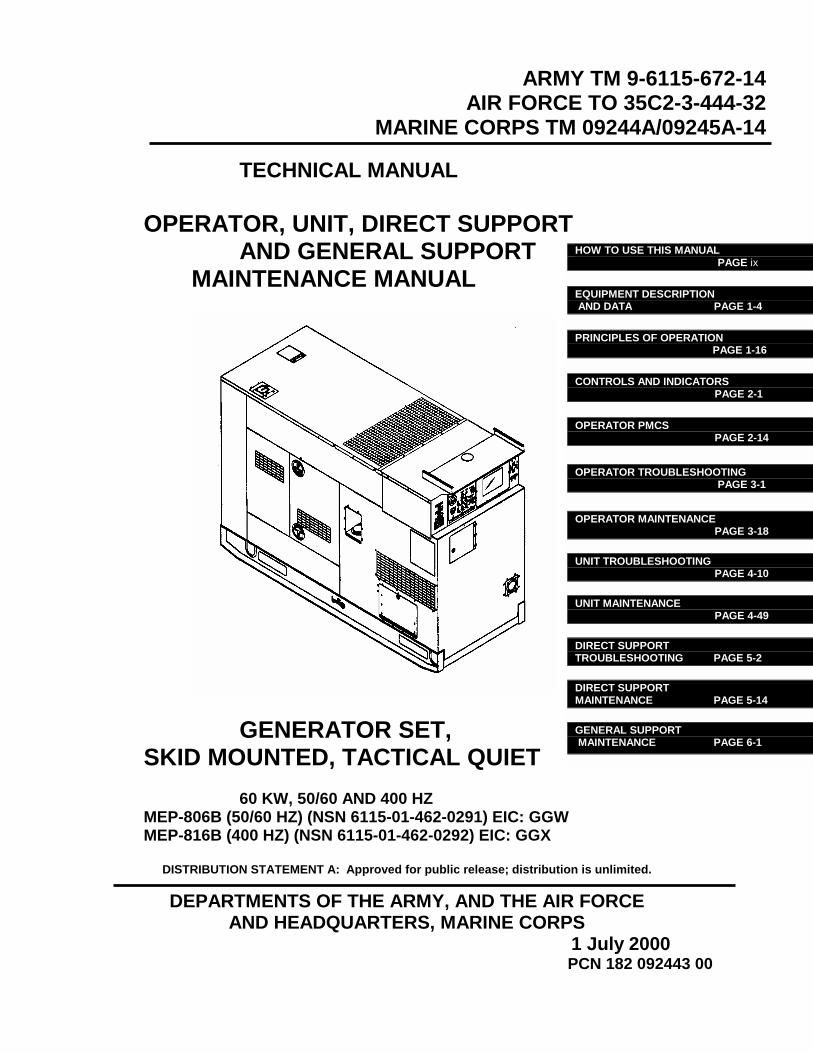
This manual contains Unit, Direct Support, and General Support maintenance instructions for the Tactical Quiet (TQ), 60 kW 50/60 and 400 Hz Generator Sets (Figure 1-1), herein referred to as generator sets. Included are descriptions of major components and their functions in relation to other components.
1.1.2 Model Numbers and Equipment Names Model Number Equipment Name
MEP-806B Generator Set, Skid Mounted, Tactical Quiet 60 kW 50/60 Hz MEP-816B Generator Set, Skid Mounted, Tactical Quiet 60 kW 400 Hz 1.2 LIMITED APPLICABILITY. Some portions of this publication are not applicable to all services. These portions are prefixed to indicate the
service(s) to which they pertain: (A) for Army, (F) for Air force, and (MC) for Marine Corps. Portions not prefixed are applicable to all services.
1.3 MAINTENANCE FORMS AND RECORDS.
(A) Maintenance forms and records used by Army Personnel are prescribed by DA PAM 738-750. (F) Maintenance forms and records used by Air Force personnel are prescribed in AFI 21-101, AFI 37-160 and the applicable TO 00-20 Series Technical Orders. (MC) Maintenance forms and records used by Marine Corps personnel are prescribed by TM 4700-15/1.
1.4 REPORTING OF ERRORS.
Reporting of errors, omissions, and recommendations for the improvement of this publication by the individual user is encouraged. Reports should be submitted as follows: (A) Army – Mail your letter, DA Form 2028 (Recommended Changes to Publications and Blank Forms), or DA Form 2028-2 located in the back of this manual direct to: Commander, U.S. Army Communications and Electronics Command (CECOM), Customer Feedback Office, ATTN: AMSEL-LC-LEO-D-CS-CFO, Fort Monmouth, New Jersey 07703-5008
(F) Air Force – AFTO Form 22 in accordance with TO-00-5-1. Mail directly to Commander, Sacramento Air Logistics Center, ATTN: TILBA, McClellan AFB, CA 95652-5990 (AFMC).

ARMY TM 9-6115-672-14 AIR FORCE TO 35C2-3-444-32 MARINE CORPS TM 09244A/09245A-14
1-2
FIGURE 1-1. 60 kW TACTICAL QUIET GENERATOR SET