
NASA TM X-2557 6TH AEROSPACE MECHANISMS ...
149
1 NASA TECHNICAL NASA TM X-2557 I MEMORANDUM h 9 e 6TH AEROSPACE MECHANISMS SYMPOSIUM George G, Herd, Editor Held at AMES RESEARCH CENTER Moffett Field, California September 9-10, 1971 NATIONAL AERONAUTICS AND SPACE ADMINISTRATION WASHINGTON, D. C. JUNE 1972
-
Upload
khangminh22 -
Category
Documents
-
view
1 -
download
0
Transcript of NASA TM X-2557 6TH AEROSPACE MECHANISMS ...
1
N A S A T E C H N I C A L NASA TM X-2557 I
M E M O R A N D U M
h 9
e
6TH AEROSPACE MECHANISMS SYMPOSIUM
George G, Herd, Editor
Held at AMES RESEARCH CENTER Moffett Field, California September 9-10, 1971
N A T I O N A L AERONAUTICS AND SPACE ADMINISTRATION WASHINGTON, D. C. JUNE 1972
I
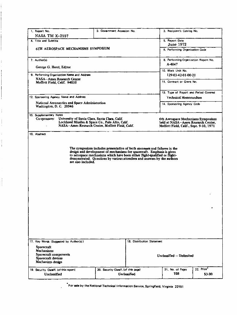
1. Report No. NASA TM X-2557
2. Government Accession No. 3. Recipient's Catalog No,
4. Title and Subtitle
6TH AEROSPACE MECHANISMS SYMPOSIUM
National Aeronautics and Space Administration Washington, D. C. 20546
5. Report Date June 1972
6. Performing Organization Code
14. Sponsoring Agency Code I
7. Authorb)
George G. Henl, Editor
9. Performing Organization Meme and Address NASA-Ames Research Center Moffett Field, Calif. 94035
-
15. Supplementary Notes Co-sponsors: University of Santa Clara, Santa Clara. Cali.
Lockheed Missiles & Space Co., Palo Alto, Calif. NASA-Ames Research Center, Moffett Field, Calif.
8. Performing Organization Report No.
A 4 4 7
10. Work Unit No. 12943-424 1-21
11. Contract or Grant No.
13. Type of Report and Period Covered -
6th Aerospace Mechanisms Symposium held at NASA-Ames Research Center, Moffett Field, Calif., Sept. 9-10.1971
19. Security Uasif. (of this report) 20. Security Claoif. (of this pagal
Unclassified UnchSsWled
16. Abstract
21. NO. of pages 22. Rice'
158 33.00
The symposium includes presentation of both succe88es and failures in the design and development of mechaniis for spacecraft. Emphasis is ken to aerospace mechanisms which have been either flightqualified or light- demonstrated. Questions by various attendees and answers by the authors are also included.
4
17. Key Words ( S u w t e d by Author(s1) 18. Distribution Statement
Spacecraft Mechanisms Spacecraft components Spacecraft devices Mechanism design
Unclassified - Unlimited
. For sale b y the National Technical Information Service, Springfield, Virginia 221 51
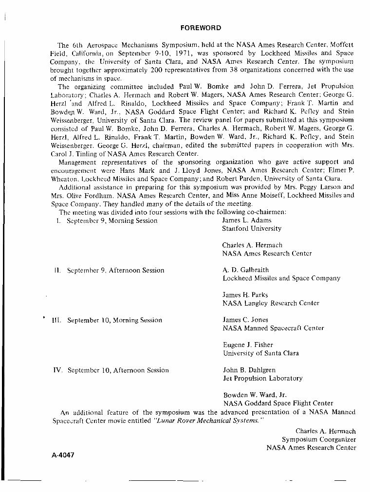
FOREWORD
The 6th Aerospace Mechanisms Symposium, held at the NASA Ames Research Center, Moffett Field, California, on September 9-10, 1971, was sponsored by Lockheed Missiles and Space Company, the University of Santa Clara, and NASA Ames Research Center. The symposium brought together approximately 200 representatives from 38 organizations concerned with the use of mechanisms in space.
The organizing committee included Paul W. Bomke and John D. Ferrera, Jet Propulsion Laboratory; Charles A. Zermach and Robert W. Magers, NASA Ames Research Center; George G. Herzl ’and Alfred L. Rinaldo, Lockheed Missiles and Space Company; Frank T. Martin and Bowde-nW. Ward. Jr.. NASA Goddard Space Flight Center; and Richard K. Pefley and Stein Weissenberger, University of Santa Clara. The review panel for papers submitted at this symposium consisted of Paul W. Bomke, John D. Ferrera, Charles A. Hermach, Robert W. Magers, George G. Herzl, Alfred L. Rinaldo, Frank T. Martin, Bowden W. Ward, Jr., Richard K. Pefley, and Stein Weissenberger. George G. Herzl, chairman, edited the submitted papers in cooperation with Mrs. Carol J . Tinling of NASA Ames Research Center.
Management representatives of the sponsoring organization who gave active support and encouragement were Hans Mark and J. Lloyd Jones, NASA Ames Research Center; Elmer P. Wheaton, Lockheed Missiles and Space Company; and Robert Parden, University of Santa Clara.
Additional assistance in preparing for this symposium was provided by Mrs. Peggy Larson and Mrs. Olive Fordham, NASA Ames Research Center, and Miss Anne Moiseff, Lockheed Missiles and Space Company. They handled many of the details of the meeting.
The meeting was divided into four sessions with the following co-chairmen: I. September 9, Morning Session James L. Adams
Stanford University
Charles A. Hermach NASA Ames Research Center
11. September 9, Afternoon Session
’ 111. September 10, Morning Session
IV. September 10, Afternoon Session
A. D. Galbraith Lockheed Missiles and Space Company
James H. Parks NASA Langley Research Center
James C. Jones NASA Manned Spacecraft Center
Eugene J. Fisher University of Santa Clara
John B. Dahlgren Jet Propulsion Laboratory
Bowden W. Ward, Jr. NASA Goddard Space Flight Center
An additional feature of the symposium was the advanced presentation of a NASA Manned
Charles A. Hermach Symposium Coorganizer
NASA Ames Research Center
Spacezaft Center movie entitled “Lunar Rover Mechanical S y s t e m ”
A-4047
~-
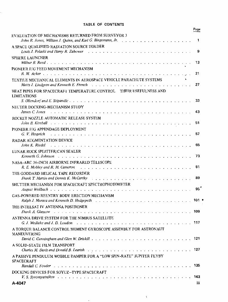
TABLE OF CONTENTS
EVALUATION OF MECHANISMS RETURNED FROM SURVEYOR 3 John R. Jones, William J. @inn, and Karl G. Bingemann, Jr.
Louis J. Polaski and Harry R. Zabower
Wilbur B. Reed . . . . . . . . . . . . . . . . . . . . . . . . . . . . . . . . . . . . . . .
R.M.Acker . .- ’ Matts J. Lindgren and Kenneth E. French
. . . . . . . . . . . . . . . . . . . A SPACE QUALIFIED RADIATION SOURCE HOLDER
SPHERE LAUNCHER
. . . . . . . . . . . . . . . . . . . . . . . . . . . .
PIONEER F/G FEED MOVEMENT MECHANISM
TEXTILE MECHANICAL ELEMENTS IN AEROSPACE VEHICLE PARACHUTE SYSTEMS
. . . . . . . . . . . . . . . . . . . . . . . . . . . . . . . . . . . . . %
. . . . . . . . . . . . . . . . . . . . . . . . . . . HEAT PIPES FOR SPACECRAF’T TEMPERATURE CONTR9L - THElR IJSEFULNESS AND LIMITATIONS
S. Ollendorf and E. Stipandic . . . . . . . . . . . . . . . . . . . . . . . . . . . . . . . . .
James C. Jones . . . . . . . . . . . . . . . . . . . . . . . . . . . . . . . . . . . . . .
Jdiit E. K i , ~ b g ! ! . . . . . . . . . . . . . . . . . . . . . . . . . . . . . . . . . . . . . .
NEUTER DOCKING-MECHANISM STUDY
ROCKET NOZZLE AUTOMATIC RELEASE SYSTEM
PIONEER F/G APPENDAGE DEPLOYMENT
RADAR AUGMENTATION DEVICE
G. V. Hesprich . . . . . . . . . . . . . . . . . . . . . . . . . . . . . . . . . . . . . .
John K. Riedel . . . . . . . . . . . . . . . . . . . . . . . . . . . . . . . . . . . . . .
Kenneth G. Johnson . . . . . . . . . . . . . . . . . . . . . . . . . . . . . . . . . . . .
R E. Mobley and R. M. Cameron
Frank T. Martin and Dennis K. McCarthy
LUNAR ROCK SPLITTER/CAN SEALER
NASA-ARC 36-INCH AIRBORNE INFRARED TELESCOPE . . . . . . . . . . . . . . . . . . . . . . . . . . . . . .
THE GODDARD HELICAL TAPE RECORDER . . . . . . . . . . . . . . . . . . . . . . . . . . .
SHUTTER MECHANISM FOR SPACECRAFT SPECTROPHOTOMETER August Weilbach . . . . . . . . . . . . . . . . . . . . . . . . . . . . . . . . . . . . . .
GAS-POWERED REENTRY BODY ERECTION MECHANISM Ralph J, Muraca and Kenneth D. Hedgepeth . . . . . . . . . . . . . . . . . . . . . . . . . .
THE INTELSAT IV ANTENNA POSITIONER Frank A. Glassow . . . . . . . . . . . . . . . . . . . . . . . . . . . . . . . . . . . . .
ANTENNA DRIVE SYSTEM FOR THE NIMBUS SATELLITE G. J. Wedlake and J. D. Loudon . . . . . . . . . . . . . . . . . . . . . . . . . . . . . . .
A TORQUE BALANCE CONTROL MOMENT GYROSCOPE ASSEMBLY FOR ASTRONAUT MANEUVERING
David C Cunningham and Glen W. Driskill . . . . . . . . . . . . . . . . . . . . . . . . . . .
Charles M. Davis and Donald B. Learish A SOLID-STATE FILM TRANSPORT
. . . . . . . . . . . . . . . . . . . . . . . . . . . . A PASSIVE PENDULUM WOBBLE DAMPER FOR A “LOW SPIN-RATE’ JUPITER FLYBY SPACECRAFT
Randall C Fowler . . . . . . . . . . . . . . . . . . . . . . . . . . . . . . . . . . . . .
V. S. Syromyatnikov . . . . . . . . . . . . . . . . . . . . . . . . . . . . . . . . . . . . DOCKING DEVICES FOR SOYUZ-TYPE SPACECRAFT
A-4047
Page - 1
9
13
21
27
33
43
51
57
65
73
81
89
95
101
109
117
121
127
135
143
iii
OPENING REMARKS
George G. Herzl Lockheed Missiles & Space Company
Sunnyvale, California
I am pleased to welcome you, on behalf of the organizing committee, to the 6th Aerospace Mechanisms Symposium. This Symposium is sponsored by the University of Santa Clara, the Lockheed Missiles Rr Spece CcmpaiIj;, a i d KASA Ames Research Center. We have here today attendees from many areas of the United States and from foreign countries, representing industry, the academic world, and government agencies.
Ben Franklin once said, “There is no better time than the present if only we know what to do with it“” No one can question the wisdom of his statement, particularly when it is employed as advice to someone other than ourselves. What t o do with our time is indeed a vital question and one that may remain with the aerospace mechanisms designer throughout the decade of the 1970’s. I would suggest that first of all we d o what we know how to do best. We should continue to develop the technology of aerospace mechanisms, being as innovative as possible. We should also continue our strong emphasis on taking full advantage of the experience gained from the development of prior mechr?nisms. In order to accomplish this we must strive to work in close cooperation with one mother. Indeed, our participation here today in the 6th Aerospace Mechanisms Symposium is evidence of a strong motivation to achieve this high order of cooperation. But times are changing! It is the recognition of this fact and the need for additional goals and directions with which I am most concerned here today.
For example, I propose that one of our major efforts be directed toward the transfer of aerospace mechanisms technology t o the solution of conventional problems. To date, there have been painfully few instances of technology transfer in our field as contrasted with the many new materials and devices from space electronics and nucleonics. At present, a number of unique aerospace mechanisms d o not have terrestrial counterparts. Examples of the kinds of mechanisms to which I refcr are the following: (1) spacecraft nutation dampers, which could be adopted for damping the oscillations of suspension cable cars in high winds, (2) yo-yo despin mechanisms, which could be employed for rapid despinning of flywheels and other rotating objects, (3) significant advancer in the impact damping techniques that were developed for lunar landing and docking in space, which should be studied more effectively for such diverse applications as automobile bumpers a n d heart valves. These are a few examples of mechanisms and techniques for which I have . personally established the feasibility and which I have tried to promote. I must confess, however, t1:at I f a i ld i n every instance. There were two main difficulties that I encountered which I believe represent the principal obstacles t o the transfer of aerospace mechanisms technology.
The first problem relates to the fact that, within the field of aerospace sciences, mechanisms design has the status of a poor relative. Our experts are called upon late in the game to solve specific dcsign problems - only after the conceptual design is frozen. In addition, soon after the project is completed the teams are dismissed until the next problem arises. This same lack of recognition carries over t o government organizations that invariably have branches concerned with electronics an3 nucleonics but seldom have a branch concerned with mechanisms that participates in conceptual design.
‘The second problem is the difficulty of promoting these ideas for use in nonaerospace applications. I t is very difficult for the individual mechanisms designer to promote ideas on his own because of his lack of contacts and resources. On the other hand, aerospace companies do not view these ideas as financially attractive; and the government agencies that should provide leadership are not primarily concerned with mechanisms.
Part of the solution to these problems therefore rests with us. As the saying goes, “It is easier to attend two conferences on the preservation of the environment than to pick up a discarded gum wrapper.” I suggest that we devote part of our next symposium in Houston to the examination of
iv A-4047
these problems. I would like to invite yoiir comments, papers, or discussions on successfu~, 2nd also unsuccessful, attempts at technology transfers. If you have any suggests, please contact me. Let's hope that we can look forward t o the implementation of an aerospace mechanism that is equivalent to, say, Teflon.
At this symposium. we have many fine papers, and I wish t o thank the authors for their efforts. I would like to encourage your aggressive and critical discussion of the papers to draw the full benefit from the information presented.
I hope that you will find your attendance a t the 6th Aerospace Mechanisms Symposium to be worthwhile and that you will enjoy your visit to the San Francisco Bay Area.
$
A-4047 V
EVALUATION OF MECHANISMS RETURNED FROM SURVEYOR 3
John R . Jones, William J. Quinn,
and Karl G. Bingemann, Jr. Hughes Aircraft Company, Culver City, California
ABSTRACT. This paper discusses the mechanisms of the TV camera and surface sampler retrieved from the Surveyor 3 spacecraft during the Apollo 12 mission. Data are presented showing the performance of these mechanisms before and after operation for one lunar day and storage for 2-1/2 years on the surface of the moon. An analysis of the critica! component materials is also given.
INTRODUCTION
The units returned from the Surveyor 3 spacecraft by the Apollo 12 astronauts provided the first example of space hardware to go the complete cycle from conception through fabrication. test, lunar operation and storage and return to earth for analysis (refs. 1 , 2). This paper presents an electrical and mechanical evaluation of the primary mechanisms and components involved, and discusses some of the materials associated with these mechanisms. The TV camera was described fully at the Second Aerospace Mechanism Symposium (ref. 3 ) ; the retrieved portion of the surface sampler mechanism is described briefly here.
The Surveyor 3 spacecraft landed on the lunar surface on April 20, 1967, and operated for 2 weeks to provide over 6000 photographs and other scientific data. After this period. the vehicle remained in “lunar storage” for 32 lunar day and night cycles (corresponding to 2-1/2 years) until the mechanisms discussed in this paper were retrieved by the Apollo 12 astronauts.
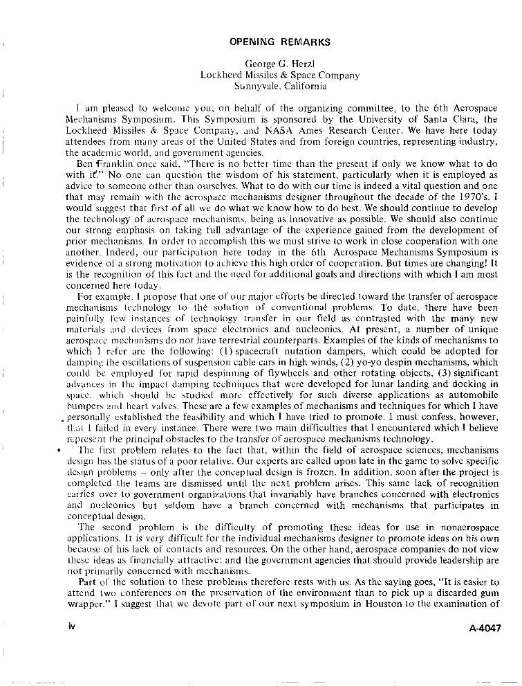
T V CAMERA MECHANISMS
The mechanisms of the retrieved TV camera that were given functional evaluation are: the mirror elevation drive, the filter wheel drive. the lens focal length and focus drives, and the focal plane shutter. The components of the mirror assembly and the filter wheel subassembly are shown in figure 1 . The components of the lens focal
POTENTIOMETER length and focus adjustments (figure 2) are essentially identical; each contains a stepper motor, a position-indicating potentiometer. and
ILTER WHEEL a gear train. Therefore, it was not considered necessary to evaluate both mechanisms under all
DRIVE MOTOR conditions. The focal length mechanism was AZIMUTH POTENT10 FILTER ASSEMBLY WHEEL tested under ambient conditions, the focus
AZIMUTH mechanism under vacuum conditions. Table 1 summarizes the operating voltage test results for MOTOR ‘BASE
~ E L E V A T I D N DRIVE
POTENTIOMETER
FILTER WHEEL
Figure 1 Mirror assembly with filter the motor driven mechanisms. wheel subassembly.
This paper presents results of one phase of research carried out at Hughes Aircraft Company, Culver City. California under contract JPL 952792 from the Jet Propulsion Laboratory, Pasadena, California and under Contract NAS9- 10492 from NASA Manned Spacecraft Center, Houston, Texas.
A-4047
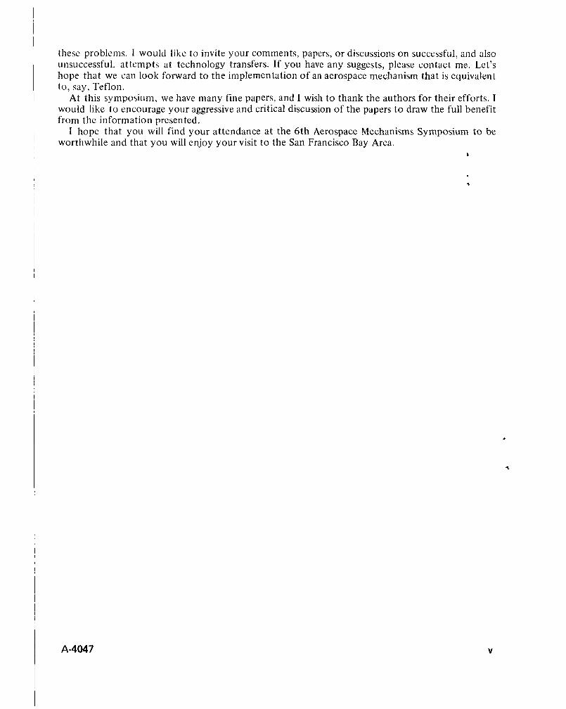
The focal plane shutter assembly consists of two solenoids, each comprising two bifilar windings, two movable blades, and associated linkages. Upon removal from the camera, one of the solenoids of the assembly was found to be charred. A resistance check revealed that coil A2 was shorted (table 2). A detailed analysis (ref. 1) indicated that a failed transistor permitted ay?p!icatim of voltage across the coil for an extended period.
An inspection of the solenoid rotor revealed that the bonded solid lubricant (Lubeco 905) had worn to the extent that areas of copper plating were visible on the pole faces. Since the shutter blade is held in the set and open positions by the retention force between the permanent magnet rotor and the
stator, the increase in breakaway current (minimum operating voltage) was attributed to wear of the bonded solid lubricant from the rotor pole face. Normal shutter operation would not be affected by the increased current, since it remained well within the capability of the camera power subsystem. Table 2 summarizes the operational test results of the shutter.
LENS BARREL IN LENS FRAME .
FOCAL LENGTH MECHANISM
FOCUS
POTENTIOMETER MOTOR
MECHANISM POTENTIOMETER
POTENTIOMETER
SHUTTER ASSEMBLY
Figure 2 Lens and shutter assembly.
I
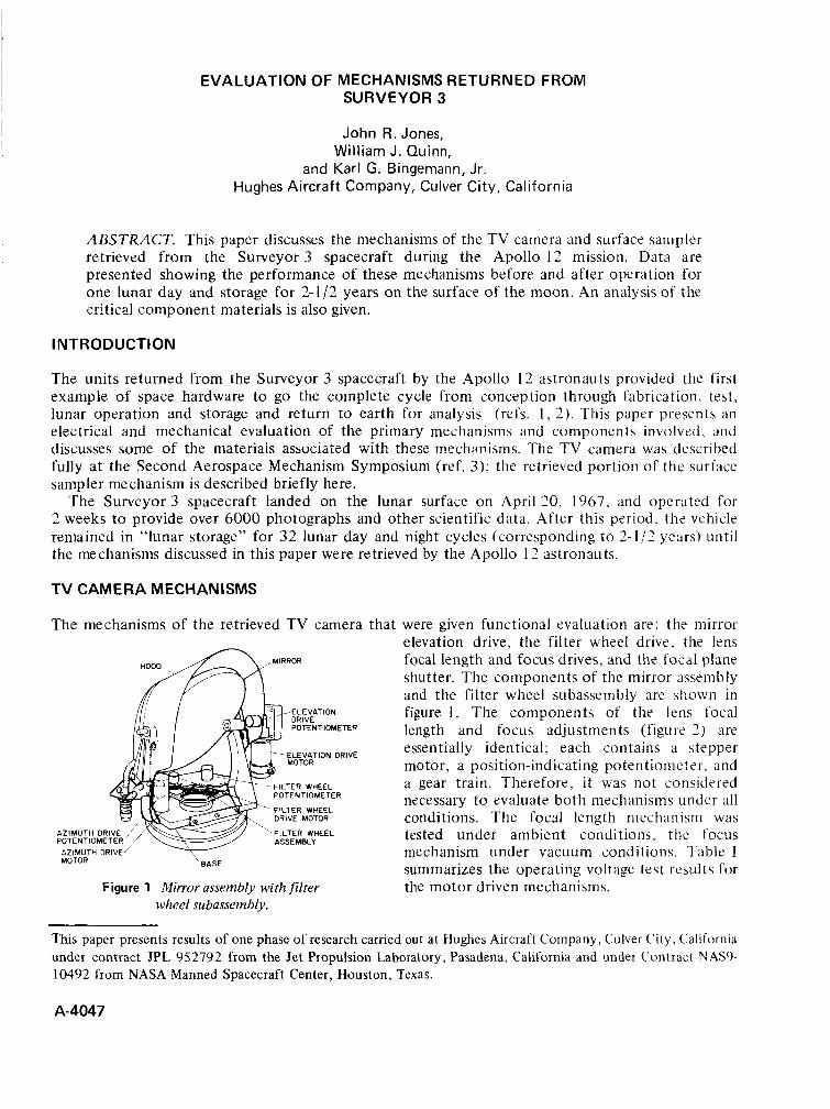
Table 1. Operating Voltage of TV Camera Mechanisms
Minimum operating uoltagk2
Nominal Nominal value, Results,
Mechanism pulse rate VDC VDC Test Condition
Mirror elevation drive, 7-9 up 8 Room ambient 14.4/1 gear ratio at 4 pps 10-12 11.7 Room ambient
h
down
Filter wheel drive, 100 pps 7.5-9.5 8.1 Room ambient 1 OO/ 1 gear ratio
Focal length drive, 1 SO/ 1 gear ratio 100 pps 7.5-9.5 9.0 Room ambient
90/1 gear ratio 16 PPS 7.5-9.5 8.8 2-4x 1 0-8 torr Focus drive,
at 25" C
aThe specification requirement for the TV camera was 14.5 VDC applied at the base connector. The nominal value corresponds to the threshold voltage required to provide absolute response to the motor to the pulsed input.
b o l t a g e s vary between step up and step down because of the action of an antibacklash spring.
2 A-4047
~~

~~ ~~
Breakaway current (at minimum operating voltage), mA
Coil Spec Measured Spec Measured
Resistance, i2
33 24 A1 33 0.2 A2
B1 33
33
33
33
190-235
190-23 5
2 5 0-3 25
2 5 0-3 2 5
SURFACE SAMPLER SCOOP MECHANISM
The scoop assembly is shown in figure 3. The door is operated by a DC motor acting through a 1400/1 reduction gear train. The door is attached to the output shaft of the gear train by a flat, clock-type spring, and is heid closed by driving it beyond its normal closed position. This creates a preload in the spring, which applies a force on the door when the motor is
-*
i
-“I a4 de-energized. The motor was manufac- -*. x*
-- tured by AiResearch, and modified by Hughes to include special brushes and pro- * *_
vide an inorganic bonded solid lubricant on the (unshielded) ball bearing. The same lubricant (Lubeco 905) was used on the
reduction gears. Table 3 compares with preflight measurements the data obtained at Hughes on the retrieved Scoop mechanism; all tests were made at 70°F.
Microscopic examination of the gears revealed a uniform run-in pattern of the solid lubricant in the contact zone (pitch line) with no appreciable wear. There was a very small amount of fine lubricant debris in the teeth roots, but no galling or metallic debris.
Examined with a Barden Smootherator, the ball bearings gave dwell ratings (roughness) of 9 to 10. On a full scale of 1 to 10, oil-lubricated precision bearings would be expected to give a dwell rating of 2 to 3.
Figure 3 Surface sample scoop mechanism.
COMPONENT EVALUATION
TV Camera Potentiometers Each of the six recovered potentiometers was a 5OOOs2 wire-wound component. All were used to indicate position of the camera mechanisms during the 2 weeks of actual operation on the moon. None of these potentiometers was lubricated. Qualification testing of unlubricated potentiometers had shown them to have a limited life expectancy satisfactory for the mission requirements of Surveyor 3 . The potentiometers used in later missions were lubricated to improve reliability.
During lunar operations one of the three-turn potentiometers failed to move past the first turn. Scanning electron microscopy, emission spectroscopy, and electron beam microprobe analysis were used t o determine the cause; which was a combination of: (1) defective guide material, (2) possible
A-4047 3
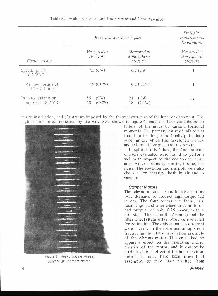
Table 3. Evaluation of Scoop Door Motor and Gear Assembly
Preflight
(minimum)
Measured ut Measured at Measured at I 0-8 torr atmospheric atmospheric
Returned Surveyor 3 part requirements
Characteristic pressure pressure
Speed. rpm @ 18.2 VDC
Applied torque of 10 ? 0.5 in-lb
In-lb to stall motor motor at 18.2 VDC
7.5 (CW) 6.7 (CW)
7.9 (CCW) 6.8 (CCW)
5 5 (CW) 21 (CW) 48 (CCW) 18 (CCW)
1
1
12
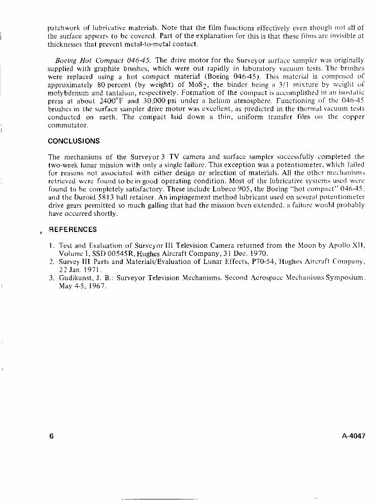
faulty installation, and (3) stresses imposed by the thermal extremes of the lunar environment. The high friction force, indicated by the wire wear shown in figure 4, may also have contributed to
Figure 4 l t ' c w fm k orr Ivircs of jocal length potentiometer.
failure of the guide by causing torsional moments. The primary cause of failure was found t o be the plastic (diallylphthallate) wiper guide, which had developed a crack and exhibited low mechanical strength.
In spite of this failure, the four potenti- ometers evaluated were found to perform well with respect to the end-to-end resist- ance, wiper continuity, starting torque, and noise. The elevation and iris pots were also checked for linearity, both in air and in vacuum.
Stepper Motors The elevation and azimuth drive motors were designed t o product high torque (20 in.-oz). The four others-the focus, iris, focal length, and filter wheel drive motors- had outputs u f only 0.25 in.-oz, with a 90" step. The azimuth (Abrams) and the filter wheel (Kearfott) motors were selected for evaluation. The only anomalies observed were a crack in the rotor and an apparent fracture in the stator lamination assembly of the Abrams motor. This crack had no apparent effect on the operating charac- teristics of the motor, and i t cannot be attributed to an effect of the lunar environ- m e n t . I t m a y have been present at assembly, or may have resulted from
A-4047

Figure 5 Gear teeth o f su~face sampler drive gear.
Figure 6 Inner race hall path elevation drive hearing - 500X.
A-4047
stresses applied during detent torque measurements. The siator fracture is attributed to stresses resulting from the i n i t i a l m a n u f a c t i i r i n g / a s s e n i b l v processes.
Lubricant Evaluation
Impingement-Applied Coating. This material is an inorganic-bonded solid lubricant applied to bearings in a two- stage process: the first, a dry abrasive blast, and second, impingement of the pigment-binder mixture onto the sur- face. The coating is approximately 50 millionths of an inch thick, and offers no corrosion protection. In all applica- tions where this lubricant was used the material failed t o prevent serious galling of mating surfaces. The coating was applied primarily t o the anodized alumi- n u m gears i n t h e T V camera potentiometer drives.
L u b e c o 9 0 5 . T h i s i s a n inorganic-bonded solid lubricant, over 90 percent (by weight) of which is ' lubricative pigments including MoS2, graphite, and lead sulfide. It is typically applied by spraying and is oven cured. Due to the inorganic binder, Lubeco 905 is somewhat hygroscopic, and special precautions must be taken with steel p a r t s t o p r e v e n t corrosion. All applications of this material were completely successful. The condition of the surfaces examined is typified in figure 5, which shows the appearance of worn Lubeco 905 on a surface sampler door drive gear.
Diiroid 5813. Commonly used for making ball bearing retainers, this is a se If-lubricating composite containing 1 5 p e r c e n t MoS2 and 15 percent fiberglass, the remaining 70 percent being PTFE. No problem occurred with this material in any of the Bartemp bearings. Figure 6 shows the appearance of the inner race ball path of the TV Camera Elevation Drive bearing at a magnification of 500X. The transfer lubrication film is clearly visible as a
5
patchwork of lubricative materials. Note that the film functions effectively even though not a l l of the surface appears to be covered. Part of the explanation for this is that these films are invisible at thicknesses that prevent metal-to-metal contact.
Boeing Hot Compuct 046-45. The drive motor for the Surveyor surface sanipler was originally supplied with graphite brushes, which were out rapidly in laboratory vacuum tests. The brushes were replaced using a hot compact material (Boeing 046-45). This material is composed of approximately 80 percent (by weight) of MoS2, the binder being a ?/! m i x t ~ r e by Wciglii of mn!ybdenum and t2iita1U111, respectively. Formation of the compact is accomplished in an isostatic press at about 2400°F and 30,000 psi under a helium atmosphere. Functioning of the 046-45 brushes in the surface sampler drive motor was excellent, as predicted in the thermal vacuum tests conducted on earth. The compact laid down a thin, uniform transfer film on the copper commutator.
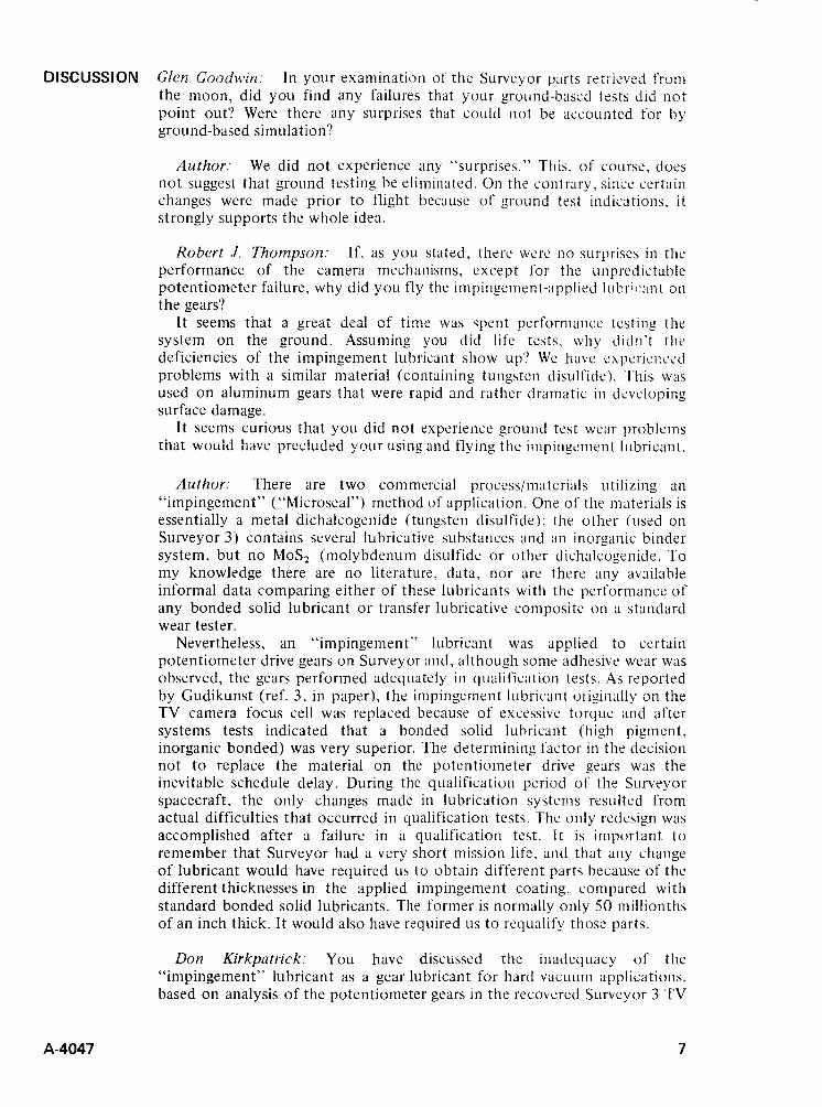
CONCLUSIONS
The mechanisms of the Surveyor 3 TV camera and surface sampler successfully completed the two-week lunar mission with only a single failure. This exception was a potentiometer, which failed for reasons not associated with either design or selection of materials. All the other mechanisms retrieved were found to be in good operating condition. Most of the lubricative systems used were found to be completely satisfactory. These include Lubeco 905, the Boeing “hot compact” 046-45, and the Duroid 58 13 ball retainer. An impingement method lubricant used on several potentiometer drive gears permitted so much galling that had the mission been extended, a failure would probably have occurred shortly.
, REFERENCES
1. Test and Evaluation of Surveyor 111 Television Camera returned from the Moon by Apollo X11, Volume I , SSD 00545R, Hughes Aircraft Company, 3 1 Dec. 1970.
2. Survey 111 Parts and Materials/Evaluation of Lunar Effects, P70-54, Hughes Aircraft Company, 22 Jan. 1971.
3. Gudikunst, J . B.: Surveyor Television Mechanisms. Second Aerospace Mechanisms Symposium. May 4-5, 1967.
6 A-4047
DISCUSSION Glen Goodwin In your examination of the Surveyor p i 1 ts iitii<.<e?, f r o ~ i the moon, did you find any failures that your ground-bascd tests did iiot point out‘? Were there any surprises that could not be accounted for by ground-based simulation?
Author: We did not experience any “surprises.” This, of course. does not suggest that ground testing be eliminated. On the contrary. since certain changes were made prior t o flight because of ground test indications, i t strongly supports the whole idea.
Robert J. Thompson: If, as you stated, there were no surprises in the performance of the camera mechanisms, except for the unpredictable potentiometer failure, why did you fly the impingement-applied luhric::int on the gears?
It seems that a great dca! ~f time wan spent perforniance testing the system on the ground. Assuming you did life tests, why didn’t the deficiencies of the impingement lubricant show up‘? We have experirncecl problems with a similar material (containing tungsten disulfide). This was used on aluminum gears that were rapid and rather dramatic i n dweloping surface damage.
It seems curious that you did not experience ground test wear problems that would h a w p:ec!uded ymrr using and flying the iinpingcment lubricant.
Author: There are two commercial process/materials utilizing an “impingement” ( “Microseal”) method of application. One of thc materials is essentially a metal dichalcogenide (tungsten disulfide ): the other (used on Surveyor 3) contains several lubricative substances and an inorganic binder system, but no MoSz (molybdenum disulfide or other dichalcogenide. To my knowledge there are no literature, data, nor are there any available informal data comparing either of these lubricants with the performance of any bonded solid lubricant o r transfer lubricative composite on a standard wear tester.
Nevertheless, an “impingement” lubricant was applied to certain potentiometer drive gears on Surveyor and, although some adhesive wear was observed, the gears performed adequately in qualification tests. As reported by Gudikunst (ref. 3, in paper), the impingement lubricant originally on the TV camera focus cell was replaced because of excessive torque and after systems tests indicated that a bonded solid lubricant (high pigment, inorganic bonded) was very superior. The determining factor in the decision not to replace the material on the potentiometer drive gears was the inevitable schedule delay. During the qualification period of the Surveyor spacecraft. the only changes made in lubrication systems resulted from actual difficulties that occurred in qualification tests. The only redesign was accomplished after a failure in a qualification test. It is important t o remember that Surveyor had a very short mission life, and that any change of lubricant would have required us to obtair, different parts because of the different thicknesses in the applied impingement coating, compared with standard bonded solid lubricants. The former is normally only 50 millionths of an inch thick. It would also have required LIS t o requalify those parts.
Don Kirkpatrick: You have discussed the inadequacy of the “impingement” lubricant as a gear lubricant for hard vacuum applications, based on analysis of the potentiometer gears in the recovered Surveyor 3 TV
A-4047 7

8
camera. Further, Jim Gudikunst, in his paper on the development of this camera presented at the 2nd Aerospace Mechanisms Symposium, reported failures of this same lubricant on the lens barrel focusing threads.
While we have not evaluated this lubricant, we have tested ball bearings lubricated with a material believed to be similar in its lubricative components, thickness. and impingement application. In our lo-' torr test, lightly loaded R-4 bearings lubricated with this other lubricant failed at considerably less than 100,000 revolutions, while the other dry lubricants evaluated exceeded !ifctimes uC lo6 to lo8 revolutions in the same test, under identical conditions. (Reported by this writer and W. C. Young at the 3rd Aerospace Mechanisms Symposium.)
In light of these unfavorable experiences with impingement-bonded dry lubricants, I am prompted t o ask whether you or any of the attendees can tell us of any successful applications of these materials for rolling or sliding contact lubrication in aerospace applications.
Author: I regret that I d o not presently know of any successful application of an impingement lubricant on a space vehicle. Naturally, this does not mean that no such application exists. I strongly doubt that there is one that could not have been better lubricated by some other method.
A-4047
A SPACE QUALIFIED RADIATION SOURCE HOLDER
Louis J. Polaski Harry R. Zabower
NASA Ames Research Center Moffett Field, California
ABSTRACT. A radiation source holder was developed to permit controlled exposure of biological material to a gamma emitting radiation source during flight in a recoverable earth orbiting satellite. A unique spring driv.: mechanism, activated by real time com- mands from the ground station, moved the 8 5 Sr source from a shielded position to the exposed position and then back to the shielded condition before reentry and recovery. A i 'diide fcature ~t!!ized the reentry deceleration force to ensure that the source would be in a shielded position during the recovery operations. The device was si.i;;essfs!!y f g w n on Biosatellite 11.
INTRODUCTION
The Biosatellite Project, NASA's first space satellite program devoted entirely to bioscience research, generated a number of requirements calling for unique and novel design approaches. Among these was the requirement that several types of biological material be exposed to ionizing radiation during a three day orbital flight.
Since the planned flight was well below the Van Allen fields of radiation, it was the judgment of the experimenters that the biological material would not be exposed to sufficient ambient radiation to ensure an adequate experiment in space. Space radiation, including the anticipated effects associated with solar flares, had been estimated to be less than 3 rads for the three days of the flight. The experiments t o be flown required total radiation dose\ of 300 to 6,000 rads. The experimenters also required that the radiation source be a well defined, controlled gamma emitter.
A comprehensive survey was made of all available radiation sources. Numerous tradeoffs with spacecraft volume, weight, electrical power, and safety requirements eliminated all but a few types of radioactive material. I t was finally decided that a 1.25 curie source of 85Sr (strontium) (0.513 MeV gamma) would be satisfactory.
REQUl REMENTS
Since a radiation source of the required strength had never been flown before, there were no spacecraft design and safety standards or guidelines. I t was decided to use the existing Atomic Energy Commission (AEC) regulations as the basis for the requirements for all flight dnd ground support equipment and procedures. After a review of the AEC regulations, the experiment require- ments, and the constraints of the spacecraft design, the following criteria were formulated:
Personnel should not be required to have any part of their body within 18 in. of an unsliielded source capsule during loading or unloading procedures.
A-4047 9
Loading and unloading of the unshielded source capsule should be accomplished in less than 10 min. A maximum radiation level of 50 mr/hr would be permitted on the outside surface of the source holder when a source capsule containing 1.25 curies * Sr was in the shielded position. The source holder would not break apart if the spacecraft impacted the ground at near terminal velocity. The source could not be accidentally exposed during ground handling. The source is to be exposed only during the weightlessness portion of the flight. The drive mechiiiiijrn shaii inciude a failsafe technique to assure that the source capsule will be in the shielded position for recovery operations.
DETAILED DESIGN
The resulting radiation source holder (RSH) design consisted of three major elements, the source holder, the source capsule, and the drive mechanism.
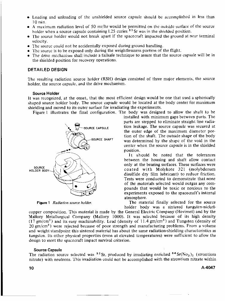
Source Holder It was recognized, at the onset, that the most efficient design would be one that used a spherically shaped source holder body. The source capsule would be located at the body center for maximum shielding and moved to its outer surface for irradiating the experiments.
Figure 1 illustrates the final configuration. The body was designed to allow the shaft t o be installed with minimum gaps between parts. The parts are stepped to eliminate straight line radia- tion leakage. The source capsule was secured at the outer edge of the maximum diameter por- tion of the shaft. The outside shape of the body was determined by the shape of the void in the center when the source capsule is in the shielded position.
I t should be noted that the tolerances between the housing and shaft allow contact only at the bearing surfaces. These surfaces were c o a t e d w i t h M olykote 32 1 (molybdenum disulfide dry film lubricant) to reduce friction. Tests were conducted t o demonstrate that none of the materials selected would outgas any com- pounds that would be toxic or noxious to the experiments exposed to the spacecraft’s internal atmosphere.
The material finally selected for the source holder body was a sintered tungsten-nickel-
copper composition. This material is made by the General Electric Company (Hevimet) and by the Mallory Metallurgical Company (Mallory 1000). I t was selected because of its high density (1 7 gm/cm3 and its easy machinability. Lead (density of 1 1.4 gm/cm3 ) and Tungsten (density of 20 gm/cm3) were rejected because of poor strength and manufacturing problems. From a volume and weight standpoint this sintered material has about the same radiation-shielding characteristics as tungsten. Its other physical properties (even at elevated temperatures) were sufficient to allow the design to meet the spacecraft impact survival criterion.
OURCE CAPSULE
SHAFT
SOURCE HOLDER BODY
Figure 1 Radiation source holder.
Source Capsule The radiation source selected was Sr(No, )2 (strontium nitrate) with neutrons. This irradiation could not be accomplished with the strontium nitrate within
Sr, produced by irradiating enriched
10 A-4047

I
the source capsule, for the capsule material W O U ! ~ hzve become radioactive and would have contributed an undesirable radiation spectrum to the experiments. The activity of the radioactive strontium sealed in the capsule had to be adjusted to allow for a decay of approximately 1 percent per day from the time that it was removed from the reactor until it was launched in the spacecraft. This time period was estimated to be two weeks. The final configuration of the source capsule is shown in figure 2 . A predetermined weight of irradiated strontium nitrate was poured into the
capsule. The plug was inserted, and the bottom was welded shut. This entire operation was done in a "hot" room through the use of mechanical
The shape of the capsule was dictated by the volume of powder to be contained, the thickness of the powder, the configuration of source handling tools, and the method of securing the capsule to the source holder body shaft. The latter was accom- plished by set screw against the bottom of the capsule, with a second set screw tightened against the first to prevent loosening during ground han-
dling or the dynamic environments of launch and reentry. The loaded source capsule could be easily
source tongs.
SOURCE manipulators. ! I
~
Figure 2 Source capsule.
I handled and inserted into the source holder with the use of slightly modified standard radiation
Drive Mechanism The primary function of the drive mechanism was to control the position of the source. If a spacecraft power failure prevented normal operations by command, the mechanism positioned the source in the locked shielded position during reentry of the spacecraft. This assured minimum
accidental exposure of the recovery personnel.
I
I radiation exposure of the experiments at greater than 1 g and, more importantly, prevented , I I
A sketch of the final configuration of the drive mechanism is shown in figure 3. Rotation of the shaft moved the source to the exposed or shielded position. The power to rotate the shaft was provided by the drive spring, and the rotation was transmitted through three gears t o the cam. The cam was pre- vented from rotating by the cam lock attached to a rotary solenoid.
When powered, the solenoid rotated the cam lock 25", allowing the cam to rotate. When the cam (and the source shaft) rotated go", the next face of the cam was stopped by the other tang of the cam lock. When power was removed from the solenoid, the cam lock rotated back to its original position permitting the cam to rotate an additional 90" before being stopped by the cam lock. This 180" movement of the cam resulted in rotating the source wheel 180" from the shielded to the exposed position.
Another power pulse to the solenoid caused the source wheel to rotate 180" back to the shielded position. Upon the completion of a cycle, starting in
the shielded position and rotating 360" the spring-loaded lock pin dropped in a hole at the end of the groove in the shaft. This prevented the shaft from rotating in either direction. T o start another cycle, the lock pin was manually pulled out of the hole and dropped in the start of the groove.
I
OURCE SHAFT
ROTARY SOLENOID DRIVE SPRING
LOCK
DRIVE MECHANJSM HOUSING II
Figure 3 Drive mechanism.
A-4047 11
In the event of a spacecraft power failure, normal shielding of the source as previously described cannot be accomplished. T o achieve shielding, a mechanical system that utilized the inertial forces of reentry was incorporated into the design. The slide assembly which included the solenoid and cam lock was mounted in a slot on the mechanism mounting bracket. The inertial forces of reentry slid the assembly forward separating the cam and cam lock. This allowed the cam and source wheel shaft to rotate under the drive spring force until the lock pin dropped in the hole a t the end of the groove. The source was then shielded and locked as if the solenoid had operated.
A spring prevented the slide assembly from moving away at low g levels. Tests de'te!-mi!:ed that the device would activate a t 5 g. Since the reentry deceieration was expected to peak at 8.5 g, the system provided a 1.7 margin of safety.
The mechanism design also had to prevent premature or accidental exposure of the source during the ground handling and launch phases of the flight. To provide this feature, the length of the cam leg in contact with the cam lock during these phases was designed so that it could not rotate past the cam lock. At source exposure, the cam leg in contact with the cam lock was short enough to rotate past the cam lock when the sliding mechanism was activated.
Two springs kept the cam and cam lock from shaking loose and disengaging under vibration. The drive spring force on the cam prevented the cam from rotating clockwise, and the solenoid return spring prevented the cam lock from rotating in the direction of solenoid motion. Since the ground handling loads were less than those of flight, accidental exposure due to sustained g, shock, or vibration was not expected during normal handling.
The source holder design minimized the probability of early exposure of the source by requiring three conditions to be satisfied for the drive mechanism to operate. First, the lock pin must be in the armed position; second, the drive spring must be wound; and third, power must be supplied to the solenoid. A microswitch attached to the source wheel shaft indicated the position (shielded or exposed) of the source via the spacecraft telemetry system.
FLIGHT HISTORY
The radiation source holder assembly was approved by the Atomic Energy Commission and flew on the Biosatellite I and Biosatellite I1 spacecraft. Biosatellite I1 was recovered and analysis of telemetry records and on board dosimetry revealed that the RSH operated as planned.
CONCLUSIONS
Presently, radiation sources are employed in industry, medicine, and scientific research. Many of the devices used t o handle and control these sources are bulky and heavy with complex controls. It is anticipated that the basic concepts of the source holder and drive mechanism described in this paper can be applied to replace existing devices when increased mobility and simplicity of operation are desired.
12 A-4047
SPHERE LAUNCHER
I
Wilbur 6. Reed Lockheed Missiles & Space Co.
Sunnyvale, Cat ifornia
ABSTRACT. The sphere launcher* presented in this paper was designed to eject a 200-lb, 15-in.-diameter sphere from a space vehicle or missile, at a velocity of 58 ft/sec without imparting excessive lateral loads to the vehicle. This launching is accomplished with the vehicle operating in vacuum conditions and under a 9-g acceleration. Two principal elements are used: a high-thrust, short-burn-time rocket motor and two unique snubbers for reducing the lateral loads to acceptable limits.
iNiRODWCTION
The ejection of any type of object from a spacecraft or missile usually produces many complex problems. The launch dynamics must provide a satisfactory safety margin within the vehicle’s structural and guidance capabilities. As usual, in vehicles of this nature, weight and available space impose severe restrictions on the design. The problem becomes critical, as the mass and ejection velocity of the object are increased, since one cannot arbitrarily increase the size of a launch vehicle.
DESIGN REQUIREMENTS
The following design parameters were established for the sphere launcher operation:
1. 2. 3. 4. 5. 6. 7. 8. 9.
Sphere diameter, 15 in. Sphere weight, I95 + 5 Ib. Launch velocity, 50 ft/sec minimum to 68 ft/sec maximum. Operation at an altitude of 200,000 f t or above. Vehicle longitudinal acceleration, 9 g at the time of sphere launch. Sphere launch to be perpendicular with respect to the vehicle longitudinal axis. Maximum lateral loads to the vehicle structure not to exceed 7000 lb. A clean sphere ejection from the vehicle; no debris or “space junk.” N o contamination of the sphere outer surface during or after ejection.
DESIGN ALTERNATIVES
Prior to establishment of the final design, four concepts were investigated
1. Mechanical springs. This concept was rejected since the kinetic energy required for sphere ejection would result in springs much too heavy, bulky and impossible to load.
2. Pyrotechnic gas generator. This concept was discarded because of high reaction forces to the vehicle, and the elaborate latching and release mechanism; also, the products of combustion would impinge upon the sphere with undesirable results.
*Developed under Contract N0003068c0303.
A-4047 13

3 .
4.
Nitrogen storage bottle. This concept was discarded because of high reaction forces; close dimensional tolerance be tween sphere and barrel; and insufficient space for the storage bottle, valves, and plumbing required. fnfluted gas bladder. This concept was rejected because of excessive reaction loads and difficulty in obtaining a perfect air seal; it also required a bulky pressure chamber and an elaborate retention and release mechanism.
Since the major problem consisted of accelerating the sphere and then absorbing the kinetic energy buildup of the ejection mechanism for deceieration, it was decided t o design two separate systems, one for accelerating the sphere and the other for decelerating the ejection mechanism. The sphere acceleration was provided by a new high-thrust rocket motor* with a short burn time. Rocket motor (Foilac propellant) thrust is very predictable, and firing under vacuum conditions has no recoil or reaction to affect the launch vehicle.
Absorption of the kinetic energy stored in the expended rocket motor and sphere piston, traveling at approximately 58 ft/sec, was accomplished by using the unique energy-absorbing properties of thin wall aluminum honeycomb fabricated in hollow cylindrical form.
Proper functioning of the system required a close time/motion sequence, with some friction loss to be compensated for.
Off-the-shelf snubbers (hydraulic, pneumatic, or spring) were found t o be unsuitable for this application mainly because of size, mounting interfaces, limited stroke, or inability to absorb the energy within the limits of the system. Also, funds and time for the design, fabrication, and testing/qualification of a hydraulic or pneumatic system were prohibitive.
FUNCTIONAL SEQUENCE OF THE LAUNCHER
With the launcher assembled as shown in figure 1, the rocket motor is ignited and as the thrust builds up to approximately 6,000 lb, the two tension studs fracture (3,000 lb each) allowing the motor to accelerate the sphere and piston along the barrel. As the sphere and piston accelerate, the two snubber rods move through the inside of the snubber piston (approximately 10 in. of free travel); this permits time for the motor to develop full thrust and burnout. Milliseconds after thrust termination a cork bumper on the snubber rod engages with the forward inner face of the snubber piston (start of sphere piston deceleration). This deceleration force is transmitted aft along the snubber piston to the rear flange, which is in contact with the precrushed end of the honeycomb cylinder. The other end of the honeycomb is trapped by the snubber housing. At the start of
deceleration the sphere separates from the piston 15 DlA SPHERE \ / ,BARREL and the remaining energy in the piston and burnt
out motor is absorbed by crushing the honey- comb cylinders.
DESIGN DETAl L
The launcher design described here and shown in figure 1 represents a different approach to launch- - t ing devices. The major individual parts are described and their function explained.
,TENSION STUD BRACKET (21 SPHERE PISTON
ROCKET MOTOR
TENSION STUD (21
SECTION E-B
ROCKET MOTOR
CLAMP RING SPHERE EJECTION
- A ' BARREL SUPPORT STRUCTURE
SECTION A A AFT VIEW
Figure 1 Sphere launcher design
Launcher Barrel Assembly This is a smooth bore, semirigid rib-reinforced structure 26.2 in. long by 16 in. inside diameter
*Developed by Lockheed Propulsion Company
14 A-4047
with :i nominal wall thickness of 0.156 in. and is machined from a forged aluminum cylinder. 'The l6.00 I.D. is h a d anodized and coated with a film of baked-on dry lubricant. The supporting structure consists of two longitudinal aluniiriuin channels permanently attached to each other and the barrel by two transverse aluminuin brackets. The lower flanges of the channels provide a mounting interface with the parent vehicle.
Sphere Piston This piston cradles and supports the sphere during vehicle launch environments; supports the rockst motor and is the moving part that ejects the sphere. The piston is fabricated from an aluminum forging with the outside diameter machined to provide a 0.020- to 0,047-in. diametrical clearance with the inside of the launcher barrel. The outside diameter is also hard anodized and dry-film lubricated to reduce friction loss. The front hemispherical surface is rnachined to the same contour as the sphere, such that the contact surface loads are distributed sufl'iciently to allow for a range of'
which engages with the sphere and is designed to remove any rotational moments induced by the vehicle launch and flight dynamics. The ai'r face of iiie pisioii is iib rcii:farccd 2nd p:o:,ides 3
mounting surface for rocket motor attachment. Two bosses. 180" apart contain two threaded steel inserts for attaching the snubber rods. Clearance holes are provided to allow the tension studs to pass through the piston.
I
I sphere materials (including Teflon). This front face also contains a 1 /"-in. diameter steel index pin, ~
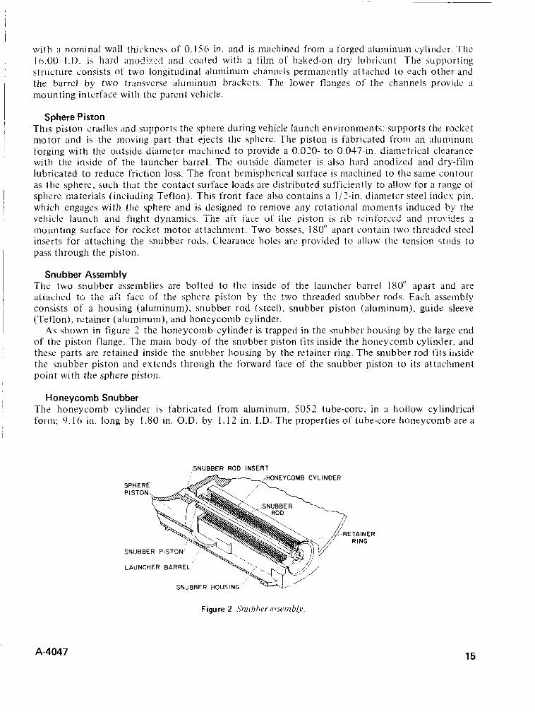
Snubber Assembly The two snubber assemblies are bolted to the inside of the launcher barrel 180" apart and are aiLaci1t.d io ilic aft facc of the sphere p i s t ~ n by the t ~ n t!ireaded sni.!bht.r rods. Each assembly consists of a housing (aluminum), snubber rod (steel), snubber piston (aluminum), guide sleeve (Teflon), retainer (aluminum), and honeycomb cylinder.
As shown in figure 2 the honeycomb cylinder is trapped in the snubber housing by the large end of the piston flange. The main body of the snubber piston fits inside the honeycomb cylinder, and these parts are retained inside the snubber housing by the retainer ring. The snubber rod fits iiiside the snubber piston and extends through the forward face of the snubber piston to its attachment point with the sphere piston.
Honeycomb Snubber The honeycomb cylinder is fabricated from aluminum, 5052 tube-core, in a hollow cylindrical form; 9.16 in. long by 1.80 in. O.D. by 1. I 2 in. I.D. The properties of tube-core honeycomb are a
SNUBBER ROD INSERT ONEYCOMB CYLINDER
S P
ETAINER RING
SNUBBER PISTON
LAUNCHER BARREL
ShUBEER HOUSI
Figure 2 Srrubhtv u\~nb!,v
A-4047 15
function of foil gage, adhesive, and cell size. These properties establish the honeycomb density that provides the load/deflection capability of the composite. Seventy-three percent of tube-core honeycomb is usable for stopping distance, and precrushing the honeycomb l /S in. eliminates the characteristic initial load spike.
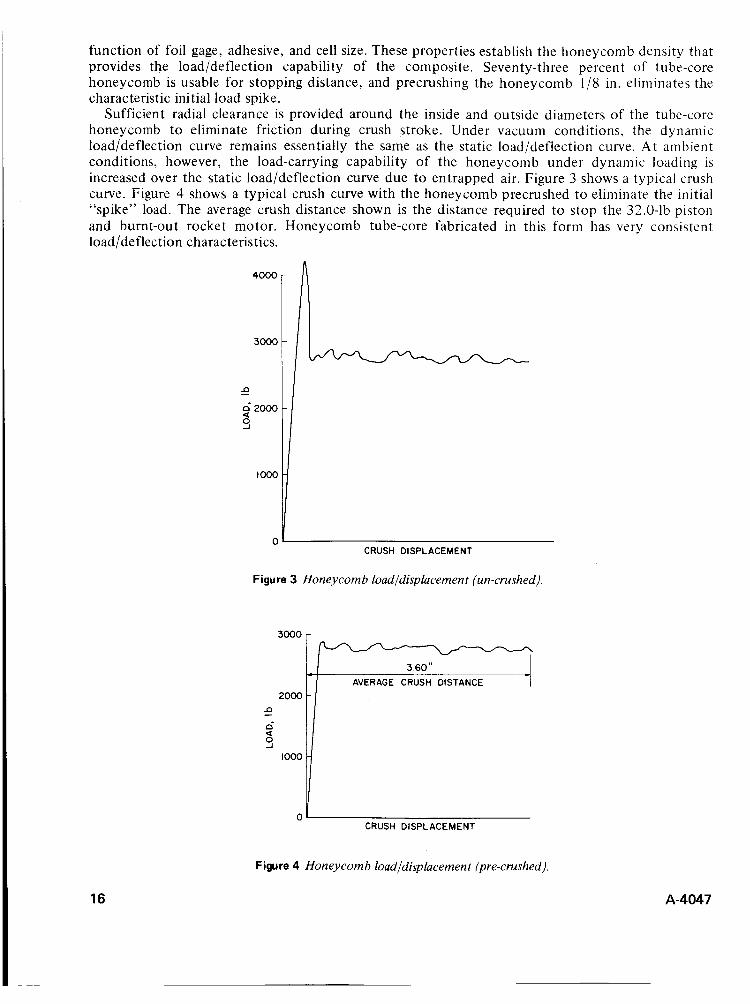
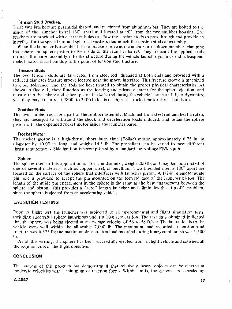
Sufficient radial clearance is provided around the inside and ou tside diameters of the tube-core honeycomb to eliminate friction during crush stroke. Under vacuum conditions, the dynamic load/deflection curve remains essentially the same as the static load/deflection curve. At ambient conditions, however, the load-carrying capability of the honeycomb under dynamic loading is increased over the static load/deflection curve due to entrapped air. Figure 3 shows a typical crush curve. Figure 4 shows a typical crush curve with the honeycomb precrushed to eliminate the initial “spike” load. The average crush distance shown is the distance required to stop the 32.0-lb piston and burnt-out rocket motor. Honeycomb tube-core fabricated in this form has very consistent load/deflection characteristics.
4000
3000
2000 n
n* a
-
s 1000
3000
- - I 3.60 ” -1
AVERAGE CRUSH DISTANCE I -
-
6 2000 a s
0 CRUSH DISPLACEMENT
Figure 3 Honeycomb loudldisplucement (un-crushed),
CRUSH DISPLACEMENT
Figure 4 Honeycomb load/displucement (pre-crushed).
16 A-4047
brackets are provided with clearance holes to allow the tension studs to pass through and provide an interface for the special nut and spherical washers that attach the tension studs at assembly.
When thc launcher is assembled, these brackets serve as the anchor or tie-down member, clamping
Tension Studs The two tension studs are fabricated from steel rod, threaded at both ends and provided with a reduced diameter fracture groove located near the sphere interface. This fracture groove is machined to close tolerance, and the rods are heat treated to obtain the proper physical characteristics. As shown in figure 1 , they function as the locking and release element for the sphere ejection, and must retain the sphere and sphere pistori in the tarre: during the vehic!e launch and flight dynamics; yet, they must fracture at 2800- to 3300-lb loads (each) as the rocket motor thrust builds up.
, Snubber Rods
The two snubber rods are a part of the snubber assembly. Machined from steel rod and heat treated, they are desinged to withstand the shock and deceleration loads induced, and retain the sphere piston with the expended rocket motor inside the launcher barrel.
Rocket Motor The rocket motor is a high-thrust, short burn time (Foilac) motor, approximately 6.75 in. in diameter by 10.00 in. long, and weighs 14.5 lb. The propellant can be varied to meet different thrust requirements. Side ignition is accomplished by a standard low-voltage EBW squib.
Sphere The sphere used in this application is 15 in. in diameter, weighs 200 lb, and may be constructed of one of several materials, such as copper, steel, or beryllium. Two threaded inserts 180” apart are located on the surface of the sphere that interfaces with launcher piston. A 1/2-in. diameter guide pin hole is provided to accept the pin mounted on the forward face of the launcher piston. The length of the guide pin engagement in the sphere is the same as the base engagement between the sphere and piston. This provides a “zero” length launcher and eliminates the “tip-off” problem, since the sphere is ejected from an accelerating vehicle.
LAUNCHER TESTING
Prior to flight test the launcher was subjected to all environmental and flight simulation tests, including successful sphere launchings under a 1 Gg acceleration. The test data obtained indicated that the sphere was being ejected at an average velocity of 56 to 58 ft/sec. The lateral loads to the vehicle were well within the allowable 7,000 lb. The maximum load recorded at tension stud fracture was 6,375 Ib; the maximum deceleration load recorded during honeycomb crush was 5,500 Ib.
As of this writing, the sphere has been successfully ejected from a flight vehicle and satisfied all the requirements of the flight objective.
CONCLUSION
The success of this program has demonstrated that relatively heavy objects can be ejected at moderate velocities with a minimum of reaction forces. Within limits, the system can be scaled up
A-4047 17
or down to meet the designers particular requirements, the mechanics of which are simple to calculate. The use of tube-core honeycomb is a one-shot application: however, the launcher hardware including rocket motor (if it can be recovered) is reusable.
Numerous applications using the honeycomb tube-core snubbing principal have been suggested; it should be remembered. however, that this system was designed to operate under vacuum conditions. To assure consistent honeycomb crush loads, adequate venting should be provided to allow entrapped air to bleed off.
The sphere used in this application is an inert mass. I t can, however, be provided with the capability of conducting a wide variety of experiments, silch as optic, e!ectremEgnetic via a ~ t e m r : and telemetry transmission. and even expelling chemicals, vapor, and other objects for scientific experiments.
18 A-4047
' DISCUSSION Don Kirkpatrick; Please describe the dry-film lubricant used in the sphere launcher. How is the surface prepared and the lube applied? Any specifications? I
Author; The sliding surface is machined to 63 microinch surface roughness and sealed with a coating of 5 percent sodium dichromate solution, pH 5.0 to 6.5 for 15 min a t 208" t o 212" F and hard anodized per M1L-A-8625, type 111, class I. Solvent clean the anodized surface and apply solid-film lubricant conforming to MIL-L-23398 (ASG), except this lube contains only molydisulfide and n o graphite or carbon. to a dry film thickness of 0.0002 to 0.0005 in. Hand burnish using lint-free wiping material t o remove all excess lubricant.
Theron Haynie: Specifically, what is the advantage of using hard-coat anodize under the dry-film lubricant?
Author: In the course of normal handling and assembly, the piston will be assembled and disassembled a number of times. Normally hard anodize gives you better wear resistance and less chance for scratches and gouges. I t also seems to give a somewhat smoother finish. We felt this justified its use.
R. L. Gaefcke: Prior to ejecting the sphere, how is the sphere retained in the piston to preveit it from falling ou t the end of the barrel?
Author; The two tension studs. The forward ends are attached to the sphere and the aft ends are attached t o the pyramid brackets bolted t o the inside of the launcher barrel. These studs clamp the sphere piston and sphere inside the barrel with sufficient force to withstand launch environments. Yet, they will fracture with rocket motor thrust buildup, allowing the sphere and piston to move along the barrel. The piston is restrained from leaving the barrel by the snubber system. Thus, only the sphere is ejected.
Ralph Muruca: In analyzing the performance of systems utilizing energy absorbers that rely on the plastic properties of materials, the effects of load application rates can significantly modify the performance of the absorber. What were the load application rates for the tension studs and the honeycomb cylinders? How were the effects of these rates determined (component test, system test, o r analytically)? Could a comparison of the variation of material properties in static versus dynamic tests be shown?
Author: The rate of load application t o the honeycomb cylinder has no effect on the cylinder's load absorption capability. In crushing, the honeycomb absorbs the energy regardless of how fast or slow the force is applied. The size of the tension studs initially was obtained by analysis. Static fracture loads were much too high, and we were forced t o employ component testing under dynamic conditions to obtain the right fracture diameter. Using the rocket motor thrustltime curve we obtained a figure of 3,300 lb applied in approximately 7 to 8 msec, which was used t o size the fracture area.
A-4047 19
PIONEER FIG FEED MOVEMENT MECHANISM
R.M. Acker T R W Systems Group
Redondo Beach, California
ABSTRACT. The Pioneer FIG spacecraft achieves the desired Earth-pointing direction through a system requiring the shifting of the main antenna feed 1 in. off axis. The feed is pivoted to this position by an electrically heated thermal actuator consisting of an electroless nickel bellows in a copper housing and filled with Freon 21. The actuator overtravels and maintains the feed in the offset position in a thermostatic limit cycle operation mode until commanded off. The mechanism is expected to operate in a -240" F environment near Jupiter and has been successfully tested at such temperatures.
INTRODUCTION
Spacecraft Considerations The Pioneer F/G spacecraft is a deep space probe that will engage in a 600- to 900-day Jupiter flyby mission taking it 500 million miles from earth. The probe will continue to provide scientific data as it goes beyond Jupiter and farther from earth, as long as the performance of the spacecraft permits. Communication with Earth is by means of a 9-ft diameter parabolic antenna whose axis is parallel to the spacecraft spin axis. Tiiiie variance of thc positioii of the spacecraft and the earth requires that the pointing attitude of the spacecraft be corrected approximately every 3 or 4 days during the early portion of the trajectory, and at gradually less frequent intervals as the spacecraft travels farther from the earth.
The spacecraft is oriented to an Earth-pointing attitude by an automatic closed-loop system, which employs a RF conical scan mode utilizing the signal radiated from the ground station. The conical scan feature is obtained by displacing the antenna feed approximately 1 in. off axis, which skews the antenna pattern producing an amplitude-modulated signal due to the conical scanning motion as the spacecraft rotates. The resultant error signal is processed to generate corrective thruster firing pulses to precess the spacecraft and achieve an accurate Earth-pointing attitude of constant signal strength. The feed is then returned to the central position for normal operation.
Design Requirements and Alternatives The principal requirements of the mechanism are:
0 Upon command, displace the feed accurately to a position 1 in. off central boresight against the resisting torque of the coaxial cable (3-in. lb maximum) in less than 26 min and, when commanded, return to the central boresight position in a comparable time period.
0 Use minimum power (4.59 W maximum). 0 Be nonmagnetic (maximum field 27 unenergized, 57 energized). 0 Achieve high reliability for a life of 500 cycles, 900 days in deep space orbit.
The use of a solenoid was considered but discarded because of the strong magnetic field induced. An electric motor was a candidate solution with a magnetic problem that could be partially corrected but only by means of a new design with attendant development problems. A silicone grease-filled actuator was proposed but rejected since it could not be incorporated in a hermetically sealed unit. The actuators were mounted in the spacecraft body and operated the feed movement
A-4047 21
A
Ilt
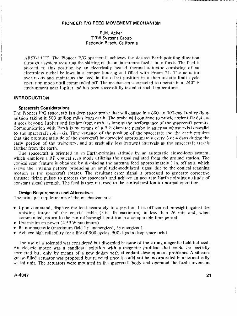
remotcly with an attendant increase in COIF
~ ! e x i t y . The t!:e::;;a! actuator that has L-- C J C C 1 1
designed and built incorporates all the mechan- ism at the feed. The feed is mounted on a 2.535-in. pivot arm and rotated 22" by an e !ectrica!!y heated thermal actuator. The mechanism is shown in figure 1 with the actuators exposed minus their normal housing of superinsulation.
DESIGN DESCRIPTION
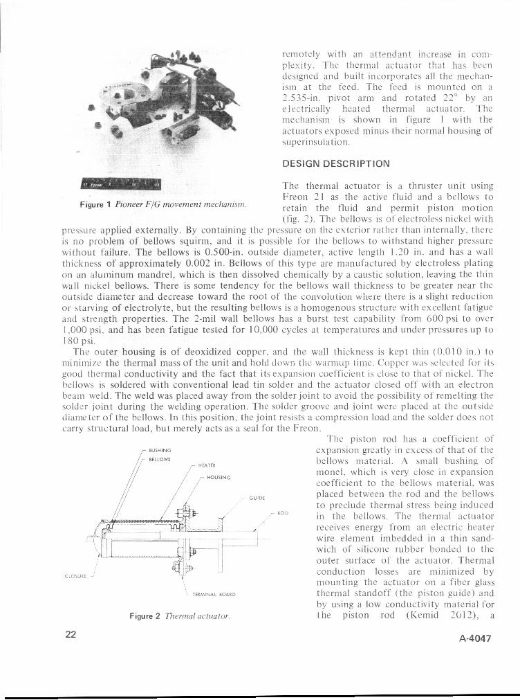
The thermal actuator is a thruster unit using Freon 21 as the active fluid and a bellows to retain the fluid and permit piston motion (fig. 2). The bellows is of electroless nickel with
prewire applied externally. By containing the pressure 011 the exterior rather than internally. there is no problem of bellows squirm, and it is possible for the bellows to withstand higher pressure without failure. The bellows is 0.500-in. outside diameter. active length 1.20 in. and has a wall thickness of approximately 0.002 in. Bellows of this type are manufactured by electroless plating on an aluminum mandrel, which is then dissolved chemically by a caustic solution, leaving the thin wall nickel bellows. There is some tendency for the bellows wall thickness to be greater near the mitsiclc d i a ix t c r and decrease toward the root of the coiivcjiuticjri wiiere there is a siigiii reduction or starving of electrolyte, but the resulting bellows is a homogenous structure with excellent fatigue and strength properties. The 2-mil wall bellows has a burst test capability from 600 psi to over 1.000 psi. and has been fatigue tested for 10,000 cycles at temperatures and under pressures up to 180 psi.
Thc outer housing is of deoxidized copper, and the wall. thickness is kept thin (0.01 0 in.) to minimize the thermal mass of the unit and hold down the warmup time. Copper was selected for its good thermal conductivity and the fact that its expansion coefficient is close to that of nickel. The bellows is soldered with conventional lead tin solder and the actuator closed off with an electron beam weld. The weld was placed away from the solder joint to avoid the possibility of remelting the solder joint during the welding operation. The solder groove and joint were placed at the outside diameter of the bellows. In this position, the joint resists a compression load and the solder does liot carry structural load, but merely acts as a seal for the Freon.
The piston rod has a coefficient of expansion greatly in excess of that of the bellows material. A small bushing of monel. which is very close i n expansion coefficient to the bellows material. was placed between the rod and the bellows to preclude thermal stress being induced i n the bellows. The thernial actuator receives energy from an electric heater wire element imbedded in a thin sand- wich of silicone rubber bonded to the outer surface of the actuator. Thermal
CLOSURE 2' conduction losses are minimized by mounting the actuator on a fiber glass thermal standoff (the piston guide) and by using a low conductivity material for the piston rod (Kemid 2012), a
Figure 1 Pioneer FIG movement mechanism.
GUIDE
.- ROD
! TERMINAL BOARD
Figure 2 Thermal actuator.
A-4047 22

polyimide with Teflon added for lubrication. The actuators are heavily insulated with thermal blankets of aluminized my!ar, and test results show that only 6.5 percent of heat loss is by radiation.
Actuators were evacuated and cooled with alcohol and dry ice. Freon was transferred by condensing liquid from the gas in the actuators with final verification of fill on a before-and-after weight basis. The fill tube was crimped and spot-welded when the proper charge had been obtained. I t was found that fluid level could be verified by X-ray, but this method of checking the amount of charge did not produce consistent results. Apparently, a portion of the charge was retained by surface tension between the bellows convolutions, producing varying depths of height for the liquid.
OPERATION
For reliability reasons, two actuators are installed on the mechanism, but only one is used at a time. The backup unit is uncoupled from the mechanism to avoid the accumulation of fatigue cycles when the unit is not in use. The actuator piston rod terminates in a deep axial pocket that traps the connecting rod. The conneciirig rud arid moves back diid forth in this pocket whcn the other actuator is stroked and bears on the bottom of the pocket when that actuator is stroked. The output of the connecting rod moves a bellcrank which is held in contact with the feed mounting plate by a leaf spring. The feed mounting plate rotates with the bellcrank until it contacts the conscan stop, at which point the bellcrank continues to move by flexing the leaf spring. The extra motion of the bellcrank is used to actuate the hermetically sealed, power control microswitches that shut off heater power. As the actuator cools, the bellcrank backs off and the switch turns the power back on. Thc forward motio:: is repeated, and the unit undergees a thermostatica!!y controlled limit cycle motion with the feed against the conscan stop during the whole period, and with the bellcrank varying the amount of its overtravel to actuate and deactuate the power control microswitches. Each actuator has two microswitches in series for greater reliability. The more common failure mode of the switch is believed to be for the points to weld closed, in which case the other switch can control the circuit. When system power is shut off, the actuator cools and a torsion spring returns the feed mounting plate to the central boresight position.
To withstand the rather severe vibration during launch, the mechanism is held in the conscan position by a pin puller with redundant cartridges that are fired shortly after the termination of the launch phase. To prevent the sudden uncontrolled return to central boresight position, both actuators are powered during launch. This also provides additional restraint to the piston rods as well.
DES I GN CONSTR A I NTS
Electroless nickel undergoes a precipitation hardening process at temperatures higher than 450" F and becomes very brittle in process, so that it shatters like glass under mild force if exposed for a sufficient period. The material also becomes magnetic as i t hardens, a problem that cannot be tolerated because the Pioneer F/G spacecraft must be magnetically clean for the experiments carried. In using a solder to retain the bellows, the soldering operation had to be done at a temperature below 450°F to avoid affecting the bellows. The 40-60 lead tin solder used had a eutectic temperature of 350" F , and the soldering was done at a nominal of 425" F. The 206" F maximum operating temperature is sufficiently below the 350" F softening temperature that solder joint strength is not compromised. The calculated shear stress on the solder is less than I O psi, and the solder has a capability of 1000 psi a t 300" F.
Establishing the lowest peak operating temperature posed another design limitation. With a given bellows and force requirement, the operating temperature can be changed in increments by selecting a different type of Freon, which then provides the desired vapor pressure a t a different temperature. With the Freon 21 chosen, near Earth the nominal unpowered temperature of the actuator (140" F) holds the feed in the conscan position. As the spacecraft travels away from Earth toward Jupiter,
A-4047 23
the mechanism cools, and sometime before 90 days the feed gradually moves and reaches the central position. During near-Earth conditions (less than 100 days after launch), the telemetry communication link is able to function satisfactorily with the high gain antenna in the conscan position, but at greater ranges the transmission rate is adversely affected by the variation in signal strength due to the offset feed. Any attempt to choose a lower actuation temperature would have delayed the date of return to the central position beyond 90 days and could have necessitated a reduction in the maximum permissible telemetry transmission rate.
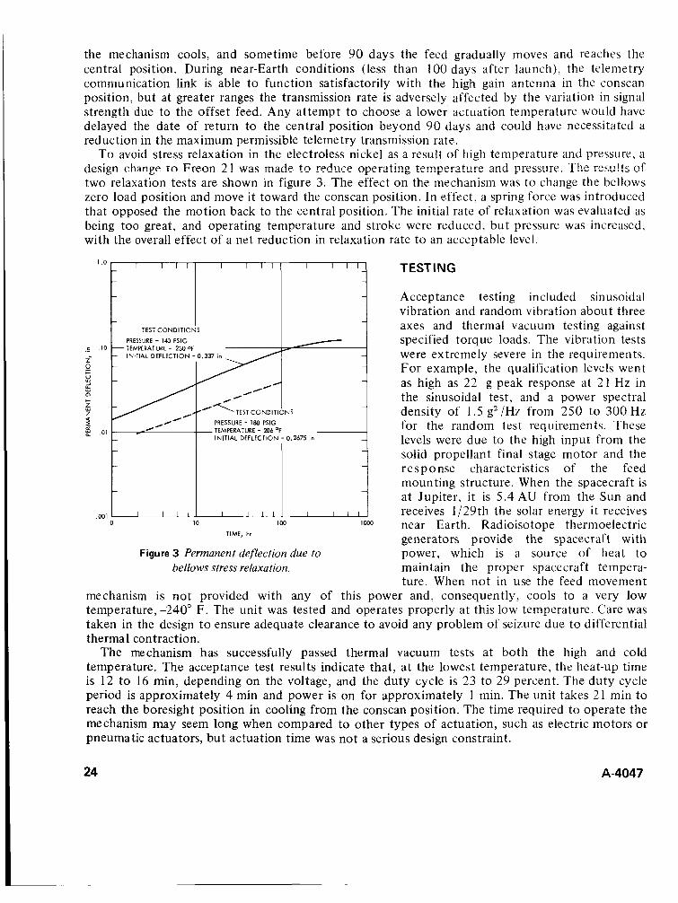
To avoid stress relaxation in the electroless nickel as a result of high temperature and pressure, a design change to Freon 2 1 was made to redwe Operating temperature and pressure. T!K res::!ts cf two relaxation tests are shown in figure 3. The effect on the mechanism was to change the bellows zero load position and move it toward the conscan position. In effect, a spring force was introduced that opposed the motion back to the central position. The initial rate of relaxation was evaluated as being too great, and operating temperature and stroke were reduced, but pressure was increased, with the overall effect of a net reduction in relaxation rate to an acceptable level.
c I O
2 P M 2 a Y
c
P 2 e .01
.Wl
PRESSURE - 140 PSlG - TEMPERATURE - 230 OF
- INITIAL DEFLECTION - 0.337 in - - -
-
-
PRESSURE - 180 PSlG TEMPERATURE - 206 OF INITIAL DEFLECTION - 0.2675 in
TIME, hr
Figure 3 Permanent deflection due to bellows stress relaxation.
TEST I NG
Acceptance testing included sinusoidal vibration and random vibration about three axes and thermal vacuum testing against specified torque loads. The vibration tests were extremely severe in the requirements. For example, the qualification levels went as high as 22 g peak response at 21 Hz in the sinusoidal test, and a power spectral density of 1.5 g2/Hz from 250 t o 300 Hz for the random test requirements. These levels were due to the high input from the solid propellant final stage motor and the response characteristics of the feed mounting structure. When the spacecraft is a t Jupiter, it is 5.4 AU from the Sun and receives 1/29th the solar energy it receives near Earth. Radioisotope thermoelectric generators provide the spacecraft with power, which is a source of heat to maintain the proper spacecraft tempera- ture. When not in use the feed movement
mechanism is not provided with any of this power and, consequently, cools to a very low temperature, -240" F. The unit was tested and operates properly at this low temperature. Care was taken in the design to ensure adequate clearance to avoid any problem of seizure due to differential therma 1 contraction.
The mechanism has successfully passed thermal vacuum tests at both the high and cold temperature. The acceptance test results indicate that, a t the lowest temperature, the heat-up time is 12 to 16 min, depending on the voltage, and the duty cycle is 23 to 29 percent. The duty cycle period is approximately 4 min and power is on for approximately 1 min. The unit takes 21 min to reach the boresight position in cooling from the conscan position. The time required to operate the mechanism may seem long when compared to other types of actuation, such as electric motors or pneumatic actuators, but actuation time was not a serious design constraint.
24 A-4047
I
CONCLUSION
The unit has been designed and demonstrated through testing to be a simple re!iabIe mechanism. The use of a hermetically sealed, Freon thermal actuator has proven to be a desirable source of motive power. Thermal actuators should be given strong consideration for spacecraft use in applications that do not require a rapid response. Such actuators offer the advantage of high rcliahility due to their simplicity, as represented by their small number of parts and minimum \ize and weight, and nonmagnetic characteristic.
Electroless nickel bellows have a high degree of flexibility, much more so than formed bellows, and are reliable with good fatigue properties. Because of the plating process, they are quite consistent in their construction and are not as prone to possible operator error, as is the case with welded bellows. Electroless nickel bellows are subject to thermal relaxation (creep) at 230" F and 206" F, with much less occurring at the lower temperature.
1
A-4047 25

DISCUSSION J. J. Orth: I would like t o know the following additional information: (1) What forces are generated by the actuator? (2) What are typical reaction times? (3) What is the piston displacement?
Author: (1) The actuator generates a 22.5-1b force. (2) At-240' F, the heat-up time is 12 to 16 min, depending on the voltage, and the cool-down time is 21 min. (3) The effective piston area is 0.141 sq in.
S. Ollendorf: Was the use of a paraffin actuator considered? For a long time in space, it seems that it would be more reliable and would not have the stress relaxation problem (ref. A-IMP S/C flux magnetometer).
Author: The actuator experiences cryogenic temperature, -240" F, which is below the brittle point of elastomers. It was believed that there would be motion induced in a paraffin actuator while the elastomeric seal material was in a brittle condition that would cause a failure.
26 A-4047

TEXTILE MECHAN!CAL ELEMENTS IN AEROSPACE VEHICLE PARACHUTE SYSTEMS
Matts J. Lindgren and Kenneth E. French Lockheed Missiles & Space Company
Sunnyvale, California
ABSTRACT. Materials, design considerations, and design details for textile mechanical elements used in aerospace vehicle parachute systems are briefly reviewed. Friction burns are noted as a major cause of parachute system failures. The friction burn hazard can be minimized by designing for predeployment and deployment sequence control with textile mechanical restraints. Two basic restraint designs (restraint loops and line ties) are discussed and various applications of the designs shown.
I NT RODUCT ION
Textiles form the basic load-carrying members in parachute systems. In addition, various textile cords, tapes, and webbings are used as parachute system mechanical elements. Mechanical applications include stow loops and line ties (analogous to mechanical retainers); closures and locking loops (latches); and risers and bridles (links). These structural and mechanical textile applications require a variety of joints and connections. In aerospace applications, the textiles/ parachutes are essentiai to mission success. They may be pressure packed and stored for an appreciable time prior to use, and may be exposed to severe flight environments.
This paper considers textiles used as mechanical elements in aerospace vehicle parachute systems. A brief review of some typical textiles and their characteristics, basic design considerations, and application and design details are presented.
Figure 1 shows an aerospace parachute recovery system. This example is not necessarily typical: para- chute systems cover too broad a spectrum (ref. 1) to detail here. As shown in figure 1 , the system functions in a sequenced series of events, many of which are determined or effected by the mechanical features of the chutes, their containers (deployment bags), and textile links between the various parts. Control signals
A,N BI\o and nontextile actuators and parts are also important elements of the overall system.
BASIC DATA
CHUTE SECTION CABLE 8 BRIDLE AS
DRAG CHUTE BAQ
MAIN CHUTE LOWER BAG ‘SPACE VEHICLE Material Characteristics
The material most commonly used in aerospace vehicle parachute systems is nylon. Occasionally Dacron@ or Nomex@ will be used for high-temperature applica- tions.* Nylon is available in several standard (military
specification or MILSPEC) forms (ref. 2). Dacron and Nomex can be obtained in but a limited number of standards and are relatively expensive. Comprehensive data on nylon, Dacron, and Nomex textile fiber properties are ’ available in the manufacturer’s literature. The data include stress-strain curves at various temperatures and extension rates, breaking strength versus time of exposure at various temperatures, and breaking strength following irradiation. In the absence of
Figure 1 Example aerospace vehicle parachute system.
-
*Dacron and Nomex are registered trademarks of E.I. du Pont de Nemours and Company, Inc.
A4047 27
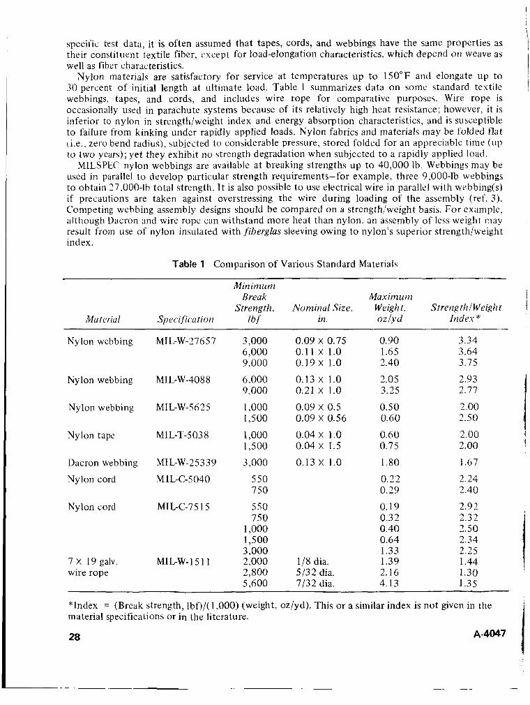
specific test data, it is often assumed that tapes, cords, and webbings have the same properties as their constituent textile fiber. except for load-elongation characteristics, which depend on weave as well as fiber characteristics.
Nylon materials are satisfactory for service at temperatures up to 150°F and elongate up to 30 percent of initial length at ultimate load. Table 1 summarizes data on some standard textile webbings, tapes, and cords, and includes wire rope for comparative purposes. Wire rope is occasionally used in parachute systems because of its relatively high heat resistance; however, it is inferior to nylon in strength/weight index and energy absorption characteristics, and is susceptible to failure from kinking under rapidly applied loads. Nylon fabrics and materials may be folded flat (Le., zero bend radius), subjected to considerable pressure, stored folded for an appreciable time (up to two years); yet they exhibit no strength degradation when subjected to a rapidly applied load.
MILSPEC nylon webbings are available at breaking strengths up to 40,000 Ib. Webbings may be used in parallel to develop particular strength requirements-for example. three 9,000-lb webbings to obtain 27,000-lb total strength. It is also possible to use electrical wire in parallel with webbing(s) if precautions are taken against overstressing the wire during loading of the assembly (ref. 3 ) . Competing webbing assembly designs should be compared on a strength/weight basis. For example, although Dacron and wire rope can withstand more heat than nylon, an assembly of less weight may result from use of nylon insulated with fiberglus slewing owing to nylon's superior strength/weight index.
Table 1 Comparison of Various Standard Materials
Miriimunz
Strength, Nominal Size, Weight, Strength f Weight Break Max inz u rn
Material Specijication lbf in. OZ/Yd Index *
Nylon webbing
Nylon webbing
Nylon webbing
Nylon tape
Dacron webbing
Nylon cord
Nylon cord
7 X 19 galv. wire rope
MIL-W-27657
MI L-W -40 8 8
MIL-W-5625
MI L-T-5 03 8
MIL-W-25339
M I L-C-5040
MIL-C-7 5 1 5
MIL-W-15 1 1
3,000 6,000 9,000
6,000 9.000
1,000 1,500
1,000 1,500
3,000
550 750
550 750
1,000 1,500 3.000 2,000 2,800 5.600
0.09 X 0.75 0.11 x 1.0 0.19 X 1.0
0.13 X 1.0 0.21 x 1.0
0.09 X 0.5 0.09 X 0.56
0.04 X 1.0 0.04 X 1.5
0.13 X 1.0
1/8 dia. 5/32 dia. 7/32 dia.
0.90 1.65 2.40
2.05 3.25
0.50 0.60
0.60 0.75
1.80
0.22 0.29
0.19 0.32 0.40 0.64 1.33 1.39 2.16 4.13
3.34 3.64 3.75
2.93 2.77
2.00 2.50
2.00 2.00
1.67
2.24 2.40
2.92 2.32 2.50 2.34 2.25 1.44 1.30 1.35
"Index = (Break strength, lbf)/( 1,000) (weight, oz/yd). This or a similar index is not given in the material specifications or in the literature.
28 A-4047
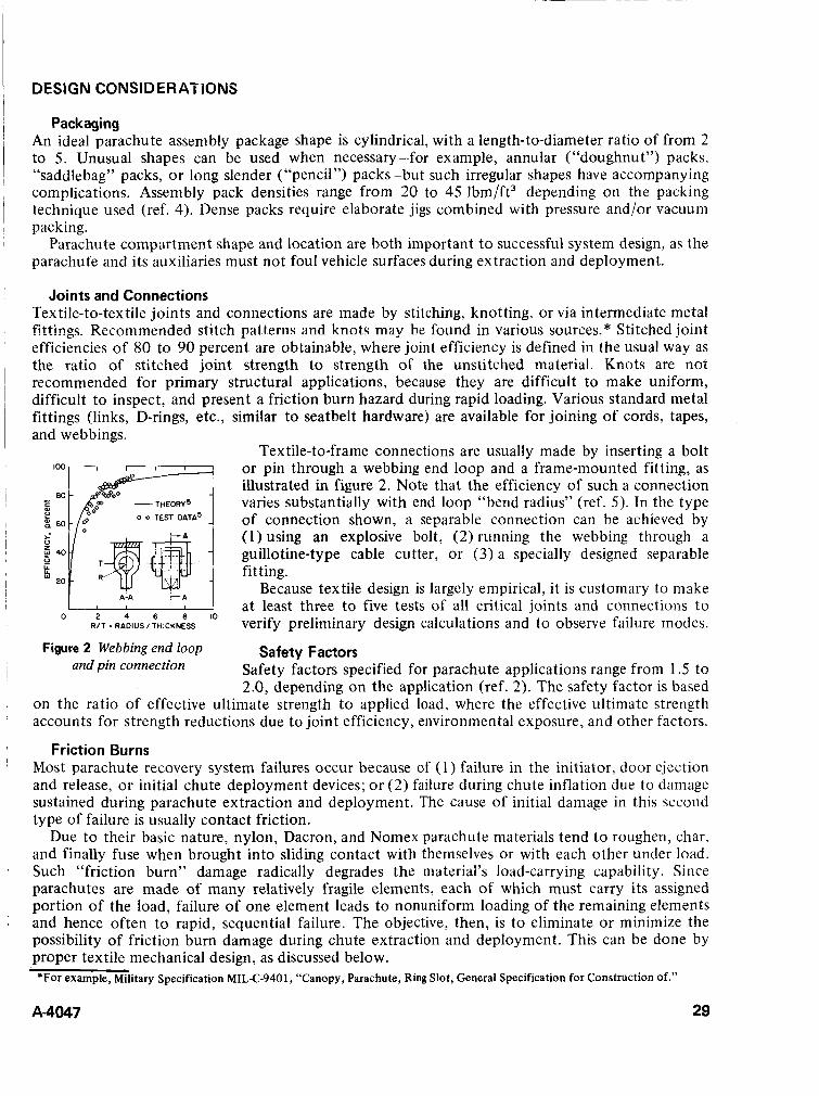
DESIGN CONSIDER ATiONS
Packaging An ideal parachute assembly package shape is cylindrical, with a length-to-diameter ratio of from 2 to 5. Unusual shapes can be used when necessary-for example, annular (“doughnut”) packs, “saddlebag” packs, o r long slender (“pencil”) packs-but such irregular shapes have accompanying complications. Assembly pack densities range from 20 to 45 lbm/ft3 depending on the packing technique used (ref. 4). Dense packs require elaborate jigs combined with pressure and/or vacuum packing.
Parachute compartment shape and location are both important t o successful system design, as the parachute and its auxiliaries must not foul vehicle surfaces during extraction and deployment.
Joints and Connections Textile-to-textile joints and connections are made by stitching, knotting, or via intermediate metal fittifigs. R-ecommended stitch patterns and knots may be found in various sources.* Stitched joint efficiencies of 80 to 90 percent are obtainable, where joint efficiency is defined in the usual way as the ratio of stitched joint strength to strength of the unstitched material. Knots are not recommended for primary structural applications, because they are difficult to make uniform, difficult to inspect, and present a friction burn hazard during rapid loading. Various standard metal fittings (links, D-rings, etc., similar to seatbelt hardware) are available for joining of cords, tapes, and webbings.
Tex tile-to-frame connections are usually made by inserting a bolt or pin through a webbing end loop and a frame-mounted fitting, as illustrated in figure 2. Note that the efficiency of such a connection varies substantially with end loop “bend radius” (ref. 5). In the type of connection shown, a separable connection can be achieved by (1) using an explosive bolt, (2) running the webbing through a guillotine-type cable cutter, or (3) a specially designed separable fitting.
Because textile design is largely empirical, it is customary to make at least three to five tests of all critical joints and connections to verify preliminary design calculations and to observe failure modes.
Safety factors specified for parachute applications range from 1.5 to 2.0, depending on the application (ref. 2). The safety factor is based
on the ratio of effective ultimate strength to applied load, where the effective ultimate strength accounts for strength reductions due to joint efficiency, environmental exposure, and other factors.
Most parachute recovery system failures occur because of (1) failure in the initiator, door ejection and release, o r initial chute deployment devices; o r (2) failure during chute inflation due to damage sustained during parachute extraction and deployment. The cause of initial damage in this second type of failure is usually contact friction.
Due t o their basic nature, nylon, Dacron, and Nomex parachute materials tend t o roughen, char. and finally fuse when brought into sliding contact with themselves or with each other under load. Such “friction burn” damage radically degrades the material’s load-carrying capability. Since parachutes are made of many relatively fragile elements, each of which must carry its assigned portion of the load, failure of one element leads to nonuniform loading of the remaining elements and hence often t o rapid, sequential failure. The objective, then, is to eliminate or minimize the possibility of friction burn damage during chute extraction and deployment. This can be done by proper textile mechanical design, as discussed below.
0 2 4 6 8 1 0 R/T = RADIUSlTHlCKNESS
Figure 2 Webbing end loop Safety Factors and pin connection
Friction Burns
*For example, Military Specification MIL-C-9401, “Canopy, Parachute, Ring Slot, General Specification for Construction Of.”
A4047 29
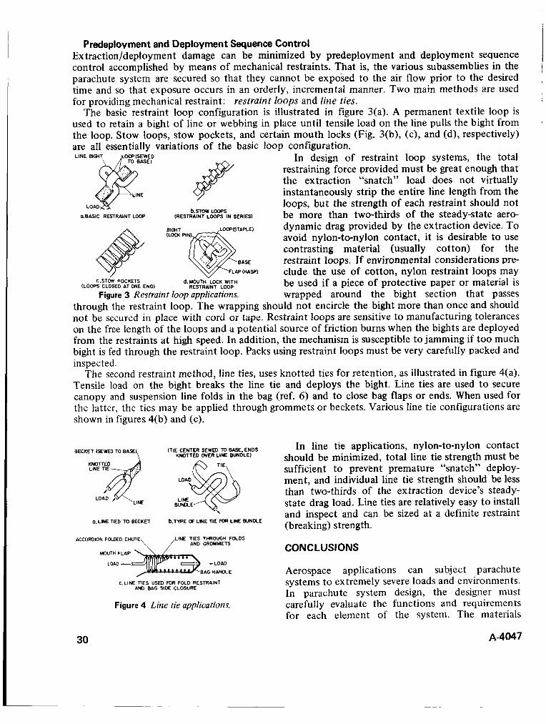
Predeplovment and Deployment Sequence Control Ex traction/deployment damage can be minimized by predeplovment and deployment sequence control accomplished by means of mechanical restraints. That is, the various subassemblies in the parachute system are secured so that they cannot be exposed to the air flow prior to the desired time and so that exposure occurs in an orderly, incremental manner. Two main methods are used for providing mechanical restraint: restraint loops and line ties.
The basic restraint loop configuration is illustrated in figure 3(a). A permanent textile loop is used to retain a bight of line or webbing in place until tensile load on the line pulls the bight from the loop. Stow loops, stow pockets, and certain mouth locks (Fig. 3(b), (c), and (d), respectively) are all essentially variations of the basic loop configuration.
D In design of restraint loop systems, the total )
restraining force provided must be great enough that the extraction “snatch” load does not virtually instantaneously strip the entire line length from the loops, but the strength of each restraint should not be more than two-thirds of the steady-state aero- dynamic drag provided by the extraction device. To avoid nylon-to-nylon contact, it is desirable to use contrasting material (usually cotton) for the restraint loops. If environmental considerations pre- clude the use of cotton, nylon restraint loops may be used if a piece of protective paper or material is
Figure 3 Restraint loop applications wrapped around the bight section that passes through the restraint loop. The wrapping should not encircle the bight more than once and should not be secured in place with cord or tape. Restraint loops are sensitive to manufacturing tolerances on the free length of the loops and a potential source of friction burns when the bights are deployed from the restraints a t high speed. In addition, the mechanism is susceptible to jamming if too much bight is fed through the restraint loop. Packs using restraint loops must be very carefully packed and inspected.
The second restraint method, line ties, uses knotted ties for retention, as illustrated in figure 4(a). Tensile load on the bight breaks the line tie and deploys the bight. Line ties are used to secure canopy and suspension line folds in the bag (ref. 6) and to close bag flaps or ends. When used for the latter, the ties may be applied through grommets or beckets. Various line tie configurations are shown in figures 4(b) and (c).
b. STOW LOOPS 0.BASIC RESTRAINT LOOP (RESTRAINT LOOPS IN SERIES1
BIGHT ~Louc PI
P(HAW
(LOOPS CLOSED AT ONE END) d.MOUTH RESTRAINT LOCK LOOP WITH C STOW POCKETS
(TIE CENTER SEWED TO BASE, ENDS In line tie applications, nylon-to-nylon contact should be minimized, total line tie strength must be sufficient to prevent premature “snatch” deploy- ment, and individual line tie strength should be less than two-thirds of the extraction device’s steady- state drag load. Line ties are relatively easy to install
KNOTTED OVER LINE BUNDLE) BECKET (SEWED TO BASE)
LINE EUNDCE LINE
and inspect and can be sized at a dkfiniie restraint (breaking) strength. O.LINE TIED TO BECKET b.TWE Cf L Y E TIE FM( LINE BUNDLE
ACCORDION FOLDED cn
MOUTH FLAP
TIES THROUGH FOLDS GROMMETS CONCLUSIONS
LOAD - -LOAD
BAG HANDLE Aerospace applications can subject parachute systems to extremely severe loads and environments. In parachute system design, the designer must carefully evaluate the functions and requirements for each element of the system. The materials
CLINE TIES USED mR FOLD RESTRAINT A N ) BAG SIDE CLOSURE
Figure 4 Line tie applications.
30 A-4047

<elected muqt be checked for compatibility with each Qther a d fsr possib!e stre~igt!? or e!.stic property changes due to heat soak. irradiation, aerodynamic heating, and the like. The strength of critical system joints and connections should be verified by tests.
Ex traction and deployment malfunctions, premature deployment, and friction burns must be guarded against in pack and compartment shape design and by using good predeployment and deployment sequence control design practices.
Because textile element design is largely empirical, it is essential that the deployment system be thoroughly bench tested and “debugged” prior to wind tunnel and drop tests. All textile mechanical elements of the proposed design should be exercised in the bench tests to ensure that the deployment sequence proceeds as planned, to evaluate restraint strengths, and to observe any undesirable extraction/deployment system dynamics (such as, too much bag rotation, asymmetrical bridle leg loading, or unanticipated contact with vehicle surfaces).
I
1 1
REFERENCES
i .
2.
3.
A f.
5.
6.
Pepper, W. B.; and Maydew, R. C . : Aerodynamic Decelerators-An Engineering Keview. J. Aircrajt,vol. 8, no. 1, Jan 1971, pp. 3-19. Anon. ; Performance of and Design Criteria for Deployable Aerodynamic Decelerators. ASD-TR-6 1-579, Dec. 1963, Air Force Flight Dynamics Laboratory, Wright-Patterson AFB, Ohio, pp. 337-358, 369-370. Pepper, W. B.: Nylon Trailing Antenna Line. J. Spacecraft and Rockets, vol. 4, no. 4, April 1967, pp. 542-543. Knacke, T. W. : R X G V Z ~ ~ Sj.‘steiiis 2nd Equipment. l’liiiidbook Asti.uiiuiiiiiui Eiigiiieeriiig (H. H. Koelle, ed.), 1st ed. McGraw-Hill, N. Y . , 1961. Section 22.5. French, K. E.: Strength of a Textile Webbing Connection. Textile Research JOUYY~UI, vol. 38, no. 2, Feb. 1968, pp. 118-122. Pepper, W. B. ; and Cronin, D. C.: Experimental Research on Parachute Deployment Load Control by Use of Line Ties. J . Aircraft, Vol. 6, No. 1 , January-February 1969, pp. 79-80.
A-4047 31

DISCUSSION R. L. Guefcke: Why are the parachute panels colored alternately orange and white?
Author: The reason for the alternating orange and white gores is to make ;it easier t o locate the parachute system either in the air or on the ground. Studies and tests have shown that this particular color pattern stands out against almost any type of background.
W. B. R e e b What is the reliability of the components and materials used in the parachute system discussed in your paper?
32
Author: This particular parachute system has been involved in 104 successive successful recoveries. This works out to be a reliability of 97.9 percent a t a confidence level of 90 percent. There have been no failures with this system.
7'. S. Clark: What kinds of mechanisms are used to perform the timing function between deployment of the rvarious elements of the parachute recovery system?
Author: Pyrotechnic devices of various types are used almost exclusively to perform these various timing functions. If the mechanism is attached to the vehicle structure it is often electrically activated using the vehicle power supply and programmer. If the device is located in the parachute system itself it is usually mechanically (lanyard) activated with a pyrotechnic time delay train providing the desired time interval between two stages in the
Examples of these types of devices include: pin pullers, pin pushers, explosive bolts, swing arm disconnects, guillotines, and reefing line cutters.
i parachute system.
A-4047
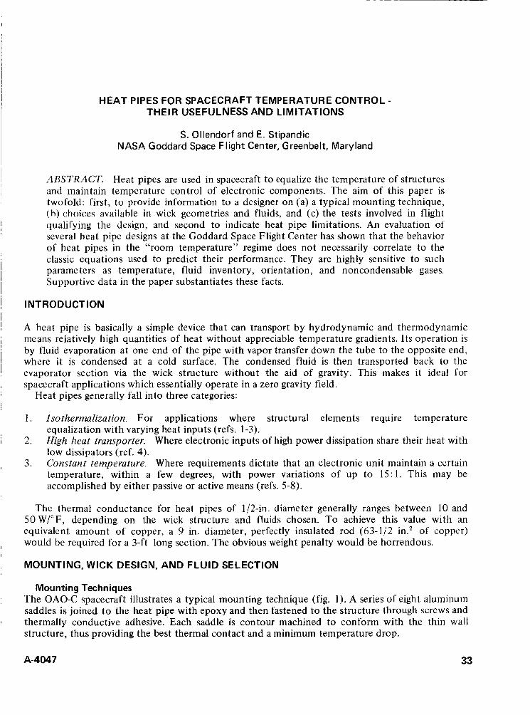
HEAT PIPES FOR SPACECRAFT TEMPERATURE CONTROL - THEIR USEFULNESS AND LIMITATIONS
S . Ollendorf and E. Stipandic NASA Goddard Space Flight Center, Greenbelt, Maryland
ABSTRACT. Heat pipes are used in spacecraft t o equalize the temperature of structures and maintain temperature control of electronic components. The aim of this paper is twofold: first, t o provide information to a designer on (a) a typical mounting technique, (h) choices available in wick geometries and fluids, and (c) the tests involved in flight qualifying the design, and second to indicate heat pipe limitations. An evaluation of several heat pipe designs at the Goddard Space Flight Center has shown that the behavior of heat pipes in the “room temperature” regime does not necessarily correlate to the classic equations used to predict their performance. They are highly sensitive to such parame ters as temperature, fluid inventory, orientation, and noncondensable gases. Supportive data in the paper substantiates these facts.
INTRODUCTION
A heat pipe is basically a simple device that can transport by hydrodynamic and thermodynamic means relatively high quantities of heat without appreciable temperature gradients. Its operation is by fluid evaporation at one end of the pipe with vapor transfer down the tube to the opposite end, where it is condensed at a cold surface. The condensed fluid is then transported back to the evaporator section via the wick structure without the aid of gravity. This makes it ideal for spacecraft applications which essentially operate in a zero gravity field.
Heat pipes generally fall into three categories:
1 . Isothermalization. For applications where structural elements require temperature equalization with varying heat inputs (refs. 1-3).
2. High heat transporter. Where electronic inputs of high power dissipation share their heat with low dissipators (ref. 4).
3. Constant temperature. Where requirements dictate that an electronic unit maintain a certain temperature, within a few degrees, with power variations of up to 15: 1. This may be accomplished by either passive or active means (refs. 5-8).
The thermal conductance for heat pipes of 1/2-in. diameter generally ranges between 10 and 50 W/”F, depending on the wick structure and fluids chosen. To achieve this value with an equivalent amount of copper, a 9 in. diameter, perfectly insulated rod (63-1/2 in.’ of copper) would be required for a 3-ft long section. The obvious weight penalty would be horrendous.
MOUNTING, WICK DESIGN, AND FLUID SELECTION
Mounting Techniques The OAO-C spacecraft illustrates a typical mounting technique (fig. 1). A series of eight aluminum saddles is joined to the heat pipe with epoxy and then fastened to the structure through screws and thermally conductive adhesive. ‘Each saddle is contour machined to conform with the thin wall structure, thus providing the best thermal contact and a minimum temperature drop.
A-4047 33
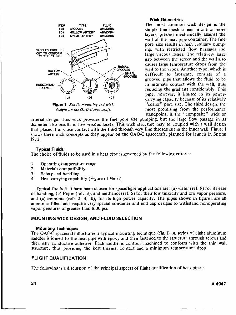
Wick Geometries ITEM TYPE F X D The most common wick design is the ( 0 ) G R O O V F AMMONIA simple fine mesh screen in one or more
layers, pressed mechanically against the wall of the heat pipe container. The fine pore size results in high capillary pump-
SADDLES PROFILE ing, with restricted flow passages and CUT TO CONFORM large viscous losses. The relatively large
gap between the screen and the wall also causes large temperature drops from the wall to the vapor. Another type, which is difficult to fabricate, consists of a grooved pipe that allows the fluid to be in intimate contact with the wall, thus reducing the gradient considerably. This pipe, however, is limited in its power- carrying capacity because of its relatively “coarse” pore size. The third design, the
designs on the OAO-C spacecraft. most promising from the performance standpoint, is the “composite” wick or
arterial design. This wick provides the fine pore size pumping, but the large flow passage in its diameter also results in low viscous losses. This wick structure may be coupled with a wall design that places it in close contact with the fluid through very fine threads cut in the inner wall. Figure 1 shows three wick concepts as they appear on the OAO-C spacecraft, planned for launch in Spring 1972.
(b) HOLLOW ARTERY AMMONIA ( C ) SPIRAL ARTERY AMMONIA
TO STRUCTURE
(a) (b) ( C )
Figure 1 Saddle mounting and wick
Typical Fluids The choice of fluids to be used in a heat pipe is governed by the following criteria:
1. Operating temperature range 2. Materials compatibility 3. Safety and handling 4. Heat-carrying capability (Figure of Merit)
Typical fluids that have been chosen for spaceflight applications are: (a) water (ref. 9) for its ease of handling, (b) Freon (ref. 13), and methanol (ref. 5 ) for their low tmxicity and low vapor pressure, and (c) ammonia (refs. 2, 3, lo), for its high power capacity. The pipes shown in figure 1 are all ammonia filled and require very special container and end cap designs to withstand nonoperating vapor pressures of greater than 1600 psi.
MOUNTING WICK DESIGN, AND FLUID SELECTION
Mounting Techniques The OAC-C spacecraft illustrates a typical mounting technique (fig. 1). A series of eight aluminum saddles is joined to the heat pipe with epoxy and then fastened to the structure through screws and thermally conductive adhesive. Each saddle is contour machined to conform with the thin wall structure, thus providing the best thermal contact and a minimum temperature drop.
FLIGHT QUAL1 FlCATlON
The following is a discussion of the principal aspects of flight qualification of heat pipes:
34 A-4047
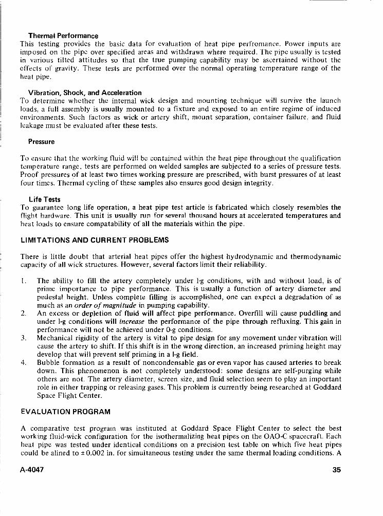
Thermal Performance This testing provides the basic data for evaluation of heat pipe perfromance. Power inputs are imposed on the pipe over specified areas and withdrawn where required. The pipe usually is tested in various tilted attitudes so that the true pumping capability may be ascertained without the effects of gravity. These tests are performed over the normal operating temperature range of the heat pipe.
Vibration, Shock, and Acceleration To determine whether the internal wick design and mounting technique will survive the launch loads, a full assembly is usually mounted to a fixture and exposed to an entire regime of induced environments. Such factors as wick or artery shift, mount separation, container failure, and fluid leakage must be evaluated after these tests.
Pressure
To ensure that the working fluid wi!! be contaimd withi:: the heat pipe througheut the qualificatim temperature range, tests are performed on welded samples are subjected to a series of pressure tests. Proof pressures of at least two times working pressure are prescribed, with burst pressures of at least four times. Thermal cycling of these samples also ensures good design integrity.
Life Tests To guarantee long life operation, a heat pipe test article is fabricated which closely resembles the flight hardwire. This unit is uriially nin for several thousand hours at accelerated temperatures and heat loads to ensure compatability of all the materials within the pipe.
LIMITATIONS AND CURRENT PROBLEMS
There is little doubt that arterial heat pipes offer the highest hydrodynamic and thermodynamic capacity of all wick structures. However, several factors limit their reliability.
1. The ability to fill the artery completely under 1-g conditions, with and without load, is of prime importance to pipe performance. This is usually a function of artery diameter and pedestal height. Unless complete filling is accomplished, one can expect a degradation of as much as an order of magnitude in pumping capability. An excess or depletion of fluid will affect pipe performance. Overfill will cause puddling and under I-g conditions will increase the performance of the pipe through refluxing. This gain in performance will not be achieved under 0-g conditions. Mechanical rigidity of the artery is vital to pipe design for any movement under vibration will cause the artery to shift. If this shift is in the wrong direction, an increased priming height may develop that will prevent self priming in a I-g field. Bubble formation as a result of noncondensable gas or even vapor has caused arteries to break down. This phenomenon is not completely understood: some designs are self-purging while others are not. The artery diameter, screen size, and fluid selection seem t o play an important role in either trapping or releasing gases. This problem is currently being researched at Goddard Space Flight Center.
2.
3 .
4.
EVALUATION PROGRAM
A comparative test program was instituted at Goddard Space Flight Center to select the best working fluid-wick configuration for the isothermalizing heat pipes on the OAO-C spacecraft. Each heat pipe was tested under identical conditions on a precision test table on which five heat pipes could be alined to ? 0.002 in. for simultaneous testing under the same thermal loading conditions. A
A-4047 35
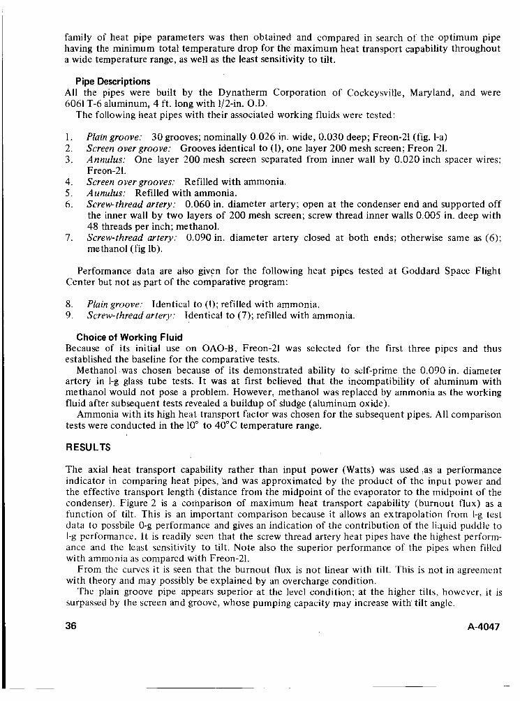
family of heat pipe parameters was then obtained and compared in search of the optimum pipe having the minimum total temperature drop for the maximum heat transport capability throughout a wide temperature range, as well as the least sensitivity to tilt.
Pipe Descriptions All the pipes were built by the Dynatherm Corporation of Cockeysville, Maryland, and were 6061 T-6 aluminum, 4 ft. long with 1/2-in. O.D.
The following heat pipes with their associated working fluids were tested:
1. 2. 3.
4. Screen over grooves: Refilled with ammonia. 5. Aunulus: Refilled with ammonia. 6.
Plain groove: 30 grooves; nominally 0.026 in. wide, 0.030 deep; Freon-21 (fig. 1-a) Screen over groove: Grooves identical to (l), one layer 200 mesh screen; Freon 21. Annulus: One layer 200 mesh screen separated from inner wall by 0.020 inch spacer wires; Freon-21.
Screwthread artery: 0.060 in. diameter artery; open at the condenser end and supported off the inner wall by two layers of 200 mesh screen; screw thread inner walls 0.005 in. deep with 48 threads per inch; methanol. Screw-thread artery: 0.090 in. diameter artery closed at both ends; otherwise same as (6); methanol (fig lb).
7.
Performance data are also given for the following heat pipes tested a t Goddard Space Flight Center but not as part of the comparative program:
8. Plain groove: Identical to (1); refilled with ammonia. 9. Screw-thread artery: Identical to ( 7 ) ; refilled with ammonia.
Choice of Working Fluid Because of its initial use on OAO-B, Freon-21 was selected for the first three pipes and thus established the baseline for the comparative tests.
Methanol was chosen because of its demonstrated ability to self-prime the 0.090 in. diameter artery in 1-g glass tube tests. I t was at first believed that the incompatibility of aluminum with methanol would not pose a problem. However, methanol was replaced by ammonia as the working fluid after subsequent tests revealed a buildup of sludge (aluminum oxide).
Ammonia with its high heat transport factor was chosen for the subsequent pipes. All comparison tests were conducted in the 10" to 40°C temperature range.
RESULTS
The axial heat transport capability rather than input power (Watts) was used ,as a performance indicator in comparing heat pipes, 'and was approximated by the product of the input power and the effective transport length (distance from the midpoint of the evaporator to the midpoint of the condenser). Figure 2 is a comparison of maximum heat transport capability (burnout flux) as a function of tilt. This is an important comparison because it allows an extrapolation from 1-g test data to possbile 0-g performance and gives an indication of the contribution of the liquid puddle to 1-g performance. It is readily seen that the screw thread artery heat pipes have the highest perform- ance and the least sensitivity to tilt. Note also the superior performance of the pipes when filled with ammonia as comparcd with Freon-21.
From the curves it is seen that the burnout flux is not linear with tilt. This is not in agreement with theory and may possibly be explained by an overcharge condition.
The plain groove pipe appears superior at the level condition; at the higher tilts, however, it is surpassed by the screen and groove, whose pumping capacity may increase with tilt angle.
36 A-4047

NOTES FOR P!PE DESCR!PT!ONS
REFER TO PAGES 6,7 ALL DATA IS FOR:
12 in. EVAPORATOR 12 in. CONDENSER
8000 gOOOA 24 in. ADIABATIC ALL HEAT INPUTS ARE
2 70001 \ INSULATION LOSSES CORRECTED FOR C
2 5000 t- 5 4000
5 3000 I
r 2 2000 E
1000
0 .2 .4 .6 .8 1.0 TILT, in.
ELEVATION OF EVAPORATOR OVER CONDENSER
Figure 2 Effect of tilt on maximum heat transport capability.
NOTES A 6 In. EVAPORATOR o 12 in. EVAPORATOR FOR PIPE DESCRIPTIONS
SEE PAGES 6.7
%/'
Q @ k301 25
NOTE ALL DATA IS FOR:
12 in. EVAPORATOR 12 in, CONDENSER
FOR PIPE DESCRIPTIONS SEE PAGES 6,7
0 I -
POWER DENSITY, W/Sq in.
Figure 3 Effect of power density on total temperature drop on the heat pipe.
I 2 3 4 5 ' 6 7 8 9 IO POWER DENSITY, W/Sq in.
Figure 4 Effect of evaporator length on the evaporator temperature drop.
In an isothermalizing heat pipe system, the temperature drop experienced in the heat pipe is a very important parameter. It becomes more important as the degree of iso- thermalization is increased. The temperature drop exhibited by a room temperature heat pipe occurs in two regions: the evaporator and condenser. Virtually no temperature drop exists in the adiabatic section, and thus the total temperature gradient on the pipe is inde- pendent of adiabatic length.
Figures 3 and 4 are comparisons of the various pipes with respect to temperature drop as a function of the radial heat flux at the level condition. Figure 3 shows the total temperature drop as a function of radial heat flux for a 12-in. evaporator and condenser. The screw thread artery has the lowest total temperature drop, while the ammonia groove shows very favorable results. In figure 4 the pipes are compared for temperature drop - -
across the evaporator only. Theoretically, the temperature drop across the evaporator due to a given radial heat flux is independent of evaporator length. This was found t o be reasonably true for all the pipes except the screw thread arteries. Figure4 shows that the temperature drops for the 6-in. evaporator were more than double those for the 12411. evaporator. This difference may be due t o the limiting performance of the screen bridging and the screw threads in distributing the liquid from the artery to the inner walls.
A-4047 37
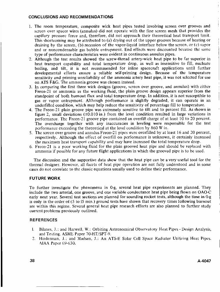
CONC LUSl ONS AND RECOMMENDATIONS
1. The room temperature, composite wick heat pipes tested involving screen over grooves and screen over spacer wires (annulus) did not operate with the fine screen mesh that provides the capillary pressure force and, therefore, did not approach their theoretical heat transport limit. This shortcoming may be attributed to (a) drying out of the upper grooves because of heating or draining by the screen, (b) recession of the vapor-liquid interface below the screen, or (c) vapor and or noncondensable gas bubble entrapment. End effects were discounted because the same type of performance characteristics were evident in continuous annulus pipes.
2. Although the test results showed the screw-thread artery-wick heat pipe to be far superior in heat transport capability and total temperature drop, as well as insensitive to fill, nucleate boiling, and tilt, it is not recommended for inline spacecraft applications until further developmental efforts ensure a reliable self-priming design. Because of the temperature sensitivity and priming unreliability of the ammonia artery heat pipe, it was not selected for use on ATS F&G. The ammonia groove was chosen instead.
3. In comparing the first three wick designs (groove, screen over groove, and annulus) with either Freon-21 or ammonia as the working fluid, the plain groove design appears superior from the standpoint of both burnout flux and total temperature drop. In addition, it is not susceptible to gas or vapor entrapment. Although performance is slightly degraded, it can operate in an underfilled condition, which may help reduce the sensitivity of percentage fill to temperature.
4. The Freon-21 plain groove pipe was extremely sensitive to tilt and to percent fill. As shown in figure 2, small deviations (+0.010 in.) from the level condition resulted in large variations in performance. The Freon-21 groove pipe contained an overfill charge of at least 10 t o 20 percent. The overcharge together with any inaccuracies in leveling were responsible for the test performance exceeding the theoretical at the level condition by 860 W in.
5. The screen over groove and annulus Freon-2 1 pipes were overfilled by at least 16 and 20 percent, respectively. Although the effect of overfill on performance is unknown, it certainly increased the maximum heat transport capability and may have increased the total temperature drop.
6. Freon-21 is a poor working fluid for the plain grooved heat pipe and should be replaced with ammonia if possible for any future flight applications in which the grooved pipe is to be used.
The discussion and the supportive data show that the heat pipe can be a very useful tool for the thermal designer. However, all facets of heat pipe operation are not fully understood and in some cases do not correlate to the classic equations usually used to define their performance.
FUTURE WORK
To further investigate the phenomena in 0-g, several heat pipe experiments are planned. They include the t w o arterial, one groove, and one variable conductance heat pipe being flown on OAO-C early next year. Several test sections are planned for sounding rocket tests, although the time in 0-g is only in the order of ( 5 to 15 min.) ground tests have shown that recovery times following burnout are within this regime. Several general heat pipe research efforts are also planned to further study current problems previously outlined.
REFERENCES
1. Bilanes, J . ; and Harwell, W.: Orbiting Astronomical Observatory Heat Pipes - Design Analysis, and Testing. ASME Paper 7O-HT/SPT-9.
2. Hinderman, J . ; and Madsen, J . : An ATS-E Solar Cell Space Radiator Utilizing Heat Pipes. AIAA Paper 69-630.
38 A-4047

3 . Eby; R.; and Kelly. W.: Thermal Control and Analysis of ATS-F&G. ASME Paper 71-AV-28. 4. Harkness, R. E.: The GEOS I1 Heat Pipe System. APL TG-1049, April, 1969. 5. Kirkpatrick, J . P.; and Marcus, B. D.: A Variable Conductance Heat Pipe Flight Experiment.
AIAA Paper 7 1-41 1. 6. Hinderman, J . ; and Waters, E.: Design and Performance of Non-Condensable Gas Controlled
Heat Pipes. AIAA Paper 7 1-420. 7. Edelstein, F.; and Hemback, R.: Design Fabrication and Testing of a Variable Conductance
Heat Pipe for Equipment Thermal Control. AIAA Paper 7 1-422. 8. Bienert, W.; Brennan, P.; and Kirkpatrick, S.: Feedback Controlled Variable Conductance Heat
Pipes. AIAA Paper 7 1-42 1. 9. Deverall, J . E.; Salmi, E. W.; and Knapp, R. J . ; Heat-Pipe Performance in a Zero Gravity Field.
J . Spacecraft Rockets, vol. 4 no. 1 1 , Nov. 1967, pp. 1556-1557. 10. Bienart, W.; and Kroliczek, E.: Experimental High Performance Heat Pipes for the OAO-C
Spacecraft. EC/LSS Conference AIAA, ASME, SAE San Francisco, Cal., July 12-14, 1971, ASME 71-AV-26.
~ A-4047 39
DISCUSSION M. P. Hollister: Have you observed gas evolution or incompatibility effects in heat pipes employing methanol and aluminum?
Author: Tests were too short to observe gas evolution, only the aluminum oxide reported in the paper.
M. P. Hollister: Have you had any experience with acetone as a working fluid?
Author: No. Fairchild is working with acetone, but we feel its performance capability is too low t o consider as a candidate. Also, RCA has built an acetone-stainless steel heat pipe, which GSFC has flown on PAC-OSO.
M. P. Hollister: Have you observed or studied the effects of boiling or gas evolution on the arterial wick design and passive designs?
Author: Yes, with the gas-controlled heat pipe we have observed gas plugging of the artery if it is tubular. However, the spiral artery being investigated by Grumman has shown particular resistance t o gas plugging and an ability to expel vapor and gas. Also, early ATS-E design with artery near wall observed boiling. Design was changed t o pedestal support.
R. Wilkes: Has any flight experience with heat pipes indicated an effect on spacecraft dynamics due t o heat pipe fluid flow? Specifically, have heat pipes any effect (adverse or otherwise) on pointing accuracy of three-axis stabilized spacecraft?
Author: There was no known observable effect on PAC (a three-axis stabilized spacecraft with six heat pipes), but there was a definite effect on ATS-E in its despin maneuvers. Refer t o “ATS-V Heat Pipe Tests and Dimensional Analysis” by J . Salvatore and W. Porter, Hughes NASA Contract NAS5-21554 T. O., R. Wirth, NASA/GSFC.
F A. Glassow: Are there cases where heat pipes have worked through articulated joints? If so, how was it accomplished? If a bellows was used at the joint, how did wicking of the fluid occur?
Author: Yes. The following are two references which describe these applications: (1) MACAP-Final Report - Fairchild Hiller for NASA/GSFC, T. O., E. Stengard; and (2)“Characteristics of Six Novel Heat Pipes,” by A. Basiulis, Hughes, ASME Paper 7 1 -Au-29.
B. W. Firth: Do the grooves on the inner pipe surface have a thermal function, in which case they can be randomly distributed, or a mechanical function, in which case they need to be continuous?
40
Author: Grooves on the inner pipe wall have a thermal function in an arterial heat pipe design in that they provide a path for fluid t o (1) wet the wall in the evaporator, and ( 2 ) return the condensed fluid to the artery. They need not be continuous axially along the pipe as long as they are in both the evaporator and the condenser.
A-4047

A-4047
For the grooved heat pipe, where the grooves are the only channel for fluid flow, i.e., open arteries. they have to be conti~iuous ;ixialIy.
NEUTER DOCK ING-M ECHAN ISM STUDY
James C. Jones NASA Manned Spacecraft Center, Houston, Texas
ABSTRACT. It is desirable, if not a firm requirement, for future spacecraft to be capable of docking without the limitation imposed by male/female docking mechanisms. Therefore, neuter (or androgynous) docking systems that allow space vehicles with similar or identical docking hardware to dock have been conceived. This paper is a discussion of basic requirements applicable to docking-mechanism design, four neuter concepts that have been studied, and the concept selected by the NASA Manned Spacecraft Center for detailed investigation.
INTRODUCTION
Early in 1966, the operational advantages of a neuter docking mechanism for use in future programs were becoming apparent. In-house studies of basic requirements were begun by NASA personnel, recognizing that future space stations and logistics spacecraft would be required to perform routine docking operations, such as for resupply and orbital assembly, and that relatively large, unobstructed docking interfaces would be required. Since 1966, efforts by NASA and industry have resulted in alternate concepts and design ideas for neuter docking mechanisms.
The docking mechanisms described herein are of the “direct docking” type, in which the vehicles are maneuvered, using their propulsive systems, to bring their docking ports into contact. Docking by use of a manipulator is also being studied; but this technique, which is in its infancy, is not included in this paper.
BASIC REQUl REMENTS
Mission Requirements Applications of a neuter docking mechanism include the orbiter vehicle of the space shuttle system, the earth-orbital space station, and other future spacecraft. Many orbiter missions require the craft to dock to spacecraft such as unmanned satellites (for resupply, o r retrieval), another orbiter, and the space station. The space station, as presently conceived, will be an assembly of several modules-each delivered to orbit by the space shuttle-that are docked together. Various experiment modules would also be delivered to the space station and docked to it. Some of the experiment modules will operate in an unmanned free-flying mode and be periodically docked to the station for maintenance and resupply. Scheduled and unscheduled replacement of modules of the space station is likely.
Requirements imposed on the docking mechanism by these missions include the following:
1. Routine transfer of crew and equipment through the docked interface without docking-
2. 3 .
4.
mechanism removal. A nominal 60-in.-diameter unobstructed passageway. Capability of withstanding numerous dockings and undockings for an extended lifetime of 5 to 10 years. Applicability to a wide variety of spacecraft configurations and mass properties.
A-4047 43
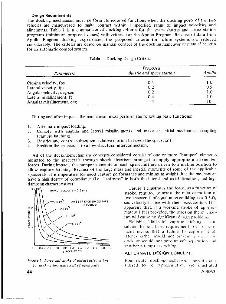
Design Requirements The docking mechanism must perform its required functions when the docking ports of the two vehicles are maneuvered to make contact within a specified range of impact velocities and alinements. Table 1 is a comparison of docking criteria for the space shuttle and space station programs (minimum proposed values) with criteria for the Apollo Program. Because of data from Apollo Program docking experiences, the proposed criteria for future systems are reduced considerably. The criteria are based on manual control of the docking maneuver or manu:lI backup for an automatic control system.
Table I Docking Design Criteria
Proposed Parameters shuttle and space station Apollo
Closing velocity, fps 0.5 1 .o Angular velocity, deg/sec 0.2 1 .o Lateral misalinement, f t 0.4 1 .o Angular misalinement, deg 4 10
Lateral velocity, fps 0.2 0.5
During and after impact, the mechanism must perform the following basic functions:
1. Attenuate impact loading. 2.
3. 4.
Comply with angular and lateral misalinements and make an initial mechanical coupling (capture latching). Restrict and control subsequent relative motion between the spacecraft. Position the spacecraft to allow structural interconnection.
All of the docking-mechanism concepts considered consist of one or more “bumper” elements mounted to the spacecraft through shock absorbers arranged to apply appropriate attenuated forces. During impact, the bumper elements on each spacecraft are driven to a mating position to allow capture latching. Because of the large mass and inertial moments of some of tht, applicable spacecraft, it is imperative for good capture performance and minimum weight that the mechanism have a high degree of compliance (i.e., “softness” in both the lateral and axial direction, and high
Figure 1 illustrates the force, as a function of stroke, required to arrest the relative motion of two spacecraft of equal mass colliding at a 0.5-ft/ sec velocity in line with their nuss centers. It is apparent that, i f a working stroke of approxi-. rnately 1 ft is provided, the loads on the J??.Lb:ii:in- ism will cause no significant design prublt i i i \ .
Reliable. “fail-safe” capture latching i \ . ~ # n - sidered to be a basic requirement. 1‘ ment meam that a failure to c;iii:<ii-\, .:I ;31i
latches either would no! prn:-n; i l . . I . ! “ * i i l
dock or would not prevent safe szparatioii and another a t t? mpt a t doc’: i ng .
ALTERNATE DESIGN CONCti??;.
I damping characteristics). IMPACT VELOCITY 0 . 5 FPS
3 lo5 (MASS OF EACH SPACECRAFT IN POUNDS)
0 0.20 .40 .60 .SO 1.0 1.2 1.4 1.6 1.8 2.0 STROKE (FEET)
Figure 1 Force and stroke of impact attenuation Four neuter doc.ki~~-- in~cha!i!~. , i i i , c:ncepts, C - > P I -
for docking two spacecraft of equal mass. sidered to be represc.ntati~8i~ are illustrated 44 A-4047
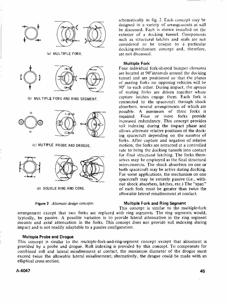
schematically in fig. 2. Each concept may be designed in a variety of arrangeiiieliis as Will be discussed. Each is shown installed on the exterior of a docking tunnel. Components such as structural latches and seals are not considered to be unique to a particular docking-mechanism concept and, therefore,
(a) MULTIPLE FORK. are not discussed.
Multiple Fork Four individual fork-shaped bumper elements are located at 90"intervals around the docking tunnel and are positioned so that the planes of mating forks on opposing vehicles will be 90" to each other. During impact, the apexes nf mating fnrks are driven together where capture latches engage them. Each fork is connected to the spacecraft through shock absorbers, several arrangements of which are possible. A minimum of three forks is required. Four or more forks provide increased redundancy. This concept provides roll indexing during the impact phase and allows alternate relative positions of the dock- ing spacecraft depending on the number of forks. After capture and negation of relative motion, the forks are retracted at a controlled rate t o bring the docking tunnels into contact for final structural latching. The forks them- selves may be employed as the final structural interconnects. The shock absorbers on one or both spacecraft may be active during docking. For some applications, the mechanism on one spacecraft may be entirely passive (ie., with- out shock absorbers, latches, etc.) The "span" of each fork must be greater than twice the ailowabie lateral misalinemen t at con tact.
(b) MULTIPLE FORK AND RING SEGMENT.
@ 0
SO@ Led v
0
(c) MUT1PI-E PROBE AND DROGUE.
(d) DOUBLE RING AND CONE.
Figure 2 Alternate design concepts. Multiple Fork and Ring Segment This concept is similar to, the multiple-fork
.arrangement except that two forks are replaced with ring segments. The ring segments would, typically, be passive. A possible variation is t o provide lateral attenuation in the ring segment mounts and axial attenuation in the forks. This concept does not provide roll indexing during impact and is not readily adaptable to a passive configuration.
Multiple Probe and Drogue This concept is similar to the multiple-fork-and-ring-segment concept except that alinement is provided by a probe and drogue. Roll indexing is provided by this concept. To compensate for combined roll and lateral misalinement at contact, the maximum diameter of the drogue must exceed twice the allowable lateral misalinement; alternatively, the drogue could be made with an elliptical cross section.
A-4047 45
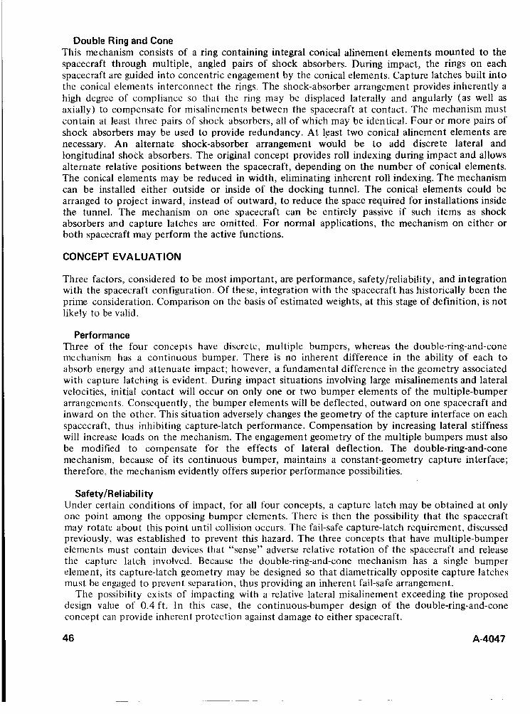
Double Ring and Cone This mechanism consists of a ring containing integral conical alinement elements mounted to the spacecraft through multiple, angled pairs of shock absorbers. During impact, the rings on each spacecraft are guided into concentric engagement by the conical elements. Capture latches built into the conical elements interconnect the rings. The shock-absorber arrangement provides inherently a high degree of compliance so that the ring may be displaced laterally and angularly (as well as axially) to compensate for misalinements between the spacecraft at contact. The mechanism must contain at least three pairs of shock absorbers, all of which may be identical. Four or more pairs of shock absorbers may be used to provide redundancy. At least two conical alinement elements are necessary. An alternate shock-absorber arrangement would be to add discrete lateral and longitudinal shock absorbers. The original concept provides roll indexing during impact and allows alternate relative positions between the spacecraft, depending on the number of conical elements. The conical elements may be reduced in width, eliminating inherent roll indexing. The mechanism can be installed either outside or inside of the docking tunnel. The conical elements could be arranged to project inward, instead of outward, to reduce the space required for installations inside the tunnel. The mechanism on one spacecraft can be entirely passive if such items as shock absorbers and capture latches are omitted. For normal applications, the mechanism on either or both spacecraft may perform the active functions.
CONCEPT EVALUATION
Three factors, considered to be most important, are performance, safety/reliability, and integration with the spacecraft configuration. Of these, integration with the spacecraft has historically been the prime consideration. Comparison on the basis of estimated weights, at this stage of definition, is not likely to be valid.
Performance Three of the four concepts have discrete, multiple bumpers, whereas the double-ring-and-cone mechanism has a continuous bumper. There is no inherent difference in the ability of each to absorb energy and attenuate impact; however, a fundamental difference in the geometry associated with capture latching is evident. During impact situations involving large misalinements and lateral velocities, initial contact will occur on only one or two bumper elements of the multiple-bumper arrangements. Consequently, the bumper elements will be deflected, outward on one spacecraft and inward on the other. This situation adversely changes the geometry of the capture interface on each spacecraft, thus inhibiting capture-latch performance. Compensation by increasing lateral stiffness will increase loads on the mechanism. The engagement geometry of the multiple bumpers must also be modified to compensate for the effects of lateral deflection. The double-ring-and-cone mechanism, because of its continuous bumper, maintains a constant-geometry capture interface; therefore, the mechanism evidently offers superior performance possibilities.
Safety/Reliability Under certain conditions of impact, for all four concepts, a capture latch may be obtained at only one point among the opposing bumper elements. There is then the possibility that the spacecraft may rotate about this point until collision occurs. The fail-safe cap ture-latch requirement, discussed previously, was established to prevent this hazard. The three concepts that have multiple-bumper elements must contain devices that “sense” adverse relative rotation of the spacecraft and release the capture latch involved. Because the double-ring-and-cone mechanism has a single bumper element, its capture-latch geometry may be designed so that diametrically opposite capture latches must be engaged to prevent separation, thus providing an inherent fail-safe arrangement.
The possibility exists of impacting with a relative lateral misalinement exceeding the proposed design value of 0.4 ft. In this case, the continuous-bumper design of the double-ring-and-cone concept can provide inherent protection against damage to either spacecraft.
46 A-4047
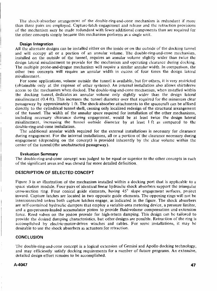
The shock-absorber arrzmgemen t of the double-ring-and-cone mechanism is redundant if more than three pairs arc cmployed. Capture-latch engagement and release and the retraction provisions of the mechanism may be made redundant with fewer additional components than are required for the other concepts simply because this mechanism performs as a single unit.
Design Integration All the alternate designs can be installed either on the inside or on the outside of the docking tunnel and will occupy all or a portion of an annular volume. The double-ring-and-cone mechanism, installed on the outside of the tunnel, requires an annular volume slightly wider than twice the design lateral misalinement to provide for the mechanism and operating clearance during docking. The multiple probe-and-drogue mechanism will require a similar annular width. In comparison, the other two concepts will require an annular width in excess of four times the design lateral misalinemen t.
For some applications, volume outside the tunnel is available, but for others, it is very restricted (obtainable only at the expense of other systems). An internal installation also allows shirtsleeve access to the mechanism when docked. The double-ring-and-cone mechanism, when installed within the docking tunnel, dedicates an annular volume only slightly wider than the design lateral misalinement (0.4 ft). This increases the tunnel diameter over that required for the minimum clear passageway by approximately I ft. The shock-absorber attachments to the spacecraft can be affixed directly to the cylindrical tunnel shell, causing only localized redesign of the structural arrangement of the tunnel. The width of the annular space required for installation of the other mechanisms, including necessary clearance during engagement, would be at least twice the design lateral misaiinement, increasing iiw iuririei outside diameter by a i least 1 ft as corriparcd to thc double-ring-and-cone installation.
The additional annular width required for the external installations is necessary for clearance during engagement. For the internal installations, all or a portion of the clearance necessary during engagement (depending on the concept) is provided inherently by the clear volume within the center of the tunnel (the unobstructed passageway).
Evaluation Summary The double-ring-and-cone concept was judged to be equal or superior to the other concepts in each of the significant areas and was chosed for more detailed definition.
DESCRIPTION OF SELECTED CONCEPT
Figure 3 is an illustration of the mechanism installed within a docking port that is applicable to a space station module. Four pairs of identical linear hydraulic shock absorbers support the triangular cross-section ring. Four conical guide elements, having 45" slope engagement surfaces, project inward. Capture latches are located in two opposite guide elements. The opposing rings will not be interconnected unless both capture latches engage, as indicated in the figure. The shock absorbers are self-contained hydraulic dampers that employ a variable-area metering device, a pressure limiter, and a gas-pressure-loaded accumulator piston to provide fluid-volume compensation and ex tension force. Reed valves on the piston provide for high-return damping. This design can be tailored to provide the desired damping characteristics, but other designs are possible. Retraction of the ring is accomplished by electric-motor-driven winches and cables. For some installations, it may be desirable t o use the shock absorbers a; actuators for retraction.
CONCLUSION
The double-ring-and-cone concept is a logical ex tension of Gemini and Apollo docking technology, and may efficiently satisfy docking requirements for a number of future programs. An extensive, detailed design effort remains to be accomplished.
A-4047 47
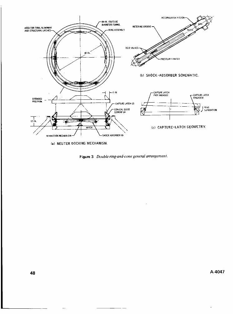
ACCUMULAIOR PISTON
DIAMETER1 TUNNEL M m R l N C GROOVE AREA FOR FINAL ALINLMENI
AND STRUCTURAL LATCHES RING ASSEMBLY
VI
,&.\ "\'.\ (c ) CAPTURE-LATCH GEOMETRY. *. ' I ,
/,,' RETRACTION MECHANISM SHOCK ABSORBER 18)
(a) NEUTER DOCKING MECHANISM.
Figure 3 Double-ring-and-cone general arrangement.
48 A-4047
DISCUSSION Louis J. Polaski: What type of pressure seal is proposed for the docking interface?
Author: There will be an identical face seal on each spacecraft, giving a “seal against seal” arrangement when the spacecraft are docked. A seal configuration similar t o a conventional elastomeric “single” seal has been designed and tested at NASA-MSC, with favorable results thus far.
R. P. Graveline: During the docking attempt o n Apollo 14, several tries were made without success. What was the problem?
Author: It was not determined exactly what the problem was. However, it was narrowed down to two possible causes: ( 1 ) contamination in the capture latch assembly, and (2) side load induced by a torque spring onto a friction sensitive transfer cam in the capture latch assembly.
The first possibiiity was corrected by process changes and handling restrictions. The second possibility was corrected by a design change.
A-4047 49

ROCKET NOZZLE AUTOMATIC RELEASE SYSTEM
John B. Kimball Lockheed Missiles 81 Space Company
Su nn yva le, Ca I i fo rn ia
ABSTRACT. The function of this mechanism is to automatically jettison a rocket nozzle element at the conclusion of boost in order to achieve a cruise mode nozzle configuration for the balance of powered flight.
The boost nozzle is retained by latched pistons that are mechanically secured until re!eased by chamher pressure, which simultaneously assumes retention of the nozzle by holding the primary piston in place. Upon attainment of cruise mode, the chamber pressure drops, allowing springs to overcome the primary piston force and pull the keeper ring forward to free the nozzle for jettison by motor exhaust. This mechanism is a part of a major LMSC program.
INTRODUCTION
It is possible that an aerodynamic vehicle can have a boost rocket burn followed by an extended air augmented cruise bum, both from a common motor. To maintain an efficient expansion ratio for the mass flows involved, it is necessary to change the rocket throat configuration for the cruise burn mode by jettisoning a boost nozzle element.
Variations in burn time could have serious effects on any type of programmed release of the boost nozzle element. One effect could be structural damage resulting from premature release during boost or a major malfunction resulting from a release that has been delayed well into the second burn period. The type of system being described herein must function in a closed control loop in order t o obtain the precise timing needed for the release of the nozzle.
The problem here is to find a reliable means for coordinating events while automatically changing the nozzle configuration during flight. Two of the basic phenomena that might be used for retaining and releasing a nozzle during rocket
burn are a buildup of burning chamber pressure and increase in temperature at the nozzle skirt due to the flow of hot gas. The pressure might be used to take over the retention of the nozzle in a ready-to-release situation after the start of the boost mode. The hot gas flow might be used to release fusible nozzle-retaining links.
In the case under discussion here, the chamber pressure available during the boost mode is approximately 900 psi and in the cruise mode approximately 100 psi. One of the parameters that confines this design is the vehicle requirement for a thin trailing edge for minimum air drag. Another important parameter is that the total boost nozzle retention force required can be in the order of 200,000 lb. To retain a nozzle under this load, rugged means must be devised for actuation in a very confined space envelope.
DES I G N D ESC R I PT I ON
The design shown in figures 1 and 2 is based on the use of chamber pressure as a means of both unlatching the system from its inactive storage condition and holding the nozzle retainer cocked, ready for release when the bum pressure reduces to cruise value.
The mechanism is contained within the thin trailing edge by placing the retention cylinders forward, while other components are made active parts of the trailing edge assembly. A collet is
A-4047 51
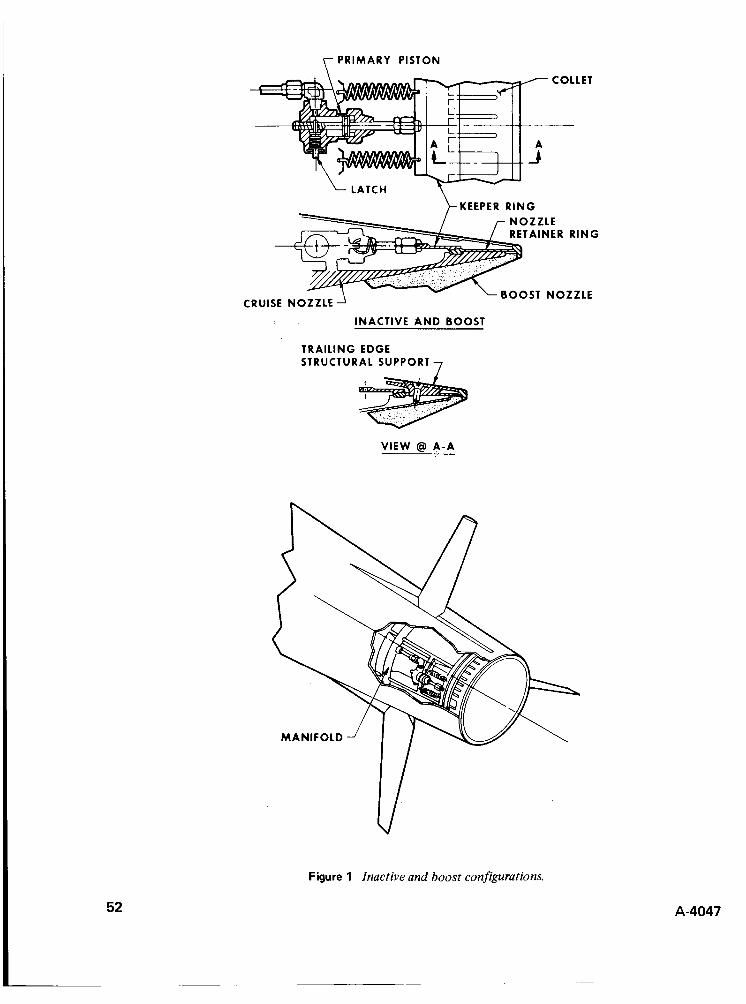
y PRIMARY PISTON
KEEPER R I N G LATCH
CRUISE NOZZLE
INACTIVE A N D BOOST
TRAILING EDGE STRUCTURAL SUPPORT 7
VIEW @l A-A
Figure 1 Inactive and boost configurations.
52 A-4047
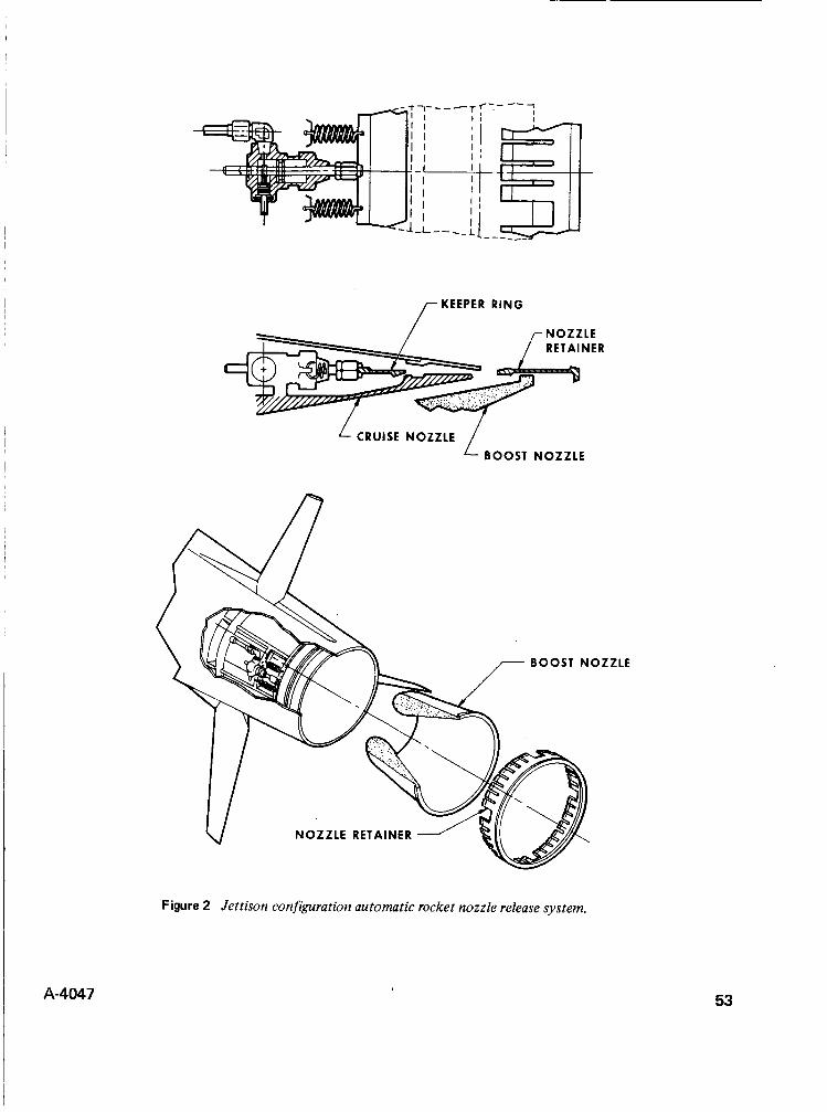
rKEEPER
CRUISE NOZZLE BOOST NOZZLE
Figure 2 Jettison configuration automatic rocket nozzle release system.
53
used for boost mode retention because of its ability to carry and distribute the large boost load uniformly around the periphery. The conclusion of boost is distinguished by a reduction of burning chamber pressure. This pressure drop initiates the moving of the system keeper ring (fig. 1 ) as the first stage toward boost nozzle ejection.
OPERATIONAL SEQUENCE
The operational sequence of this system is as follows:
1 . Latches hold the primary pistons in place. 2. Upon ignition, the chamber pressure unlatches the pistons and takes over retention of the keeper
3. At the conclusion of boost, piston force is reduced, and the springs pull the keeper ring forward. 4. The nozzle retainer collet is released and is jettisoned along with the nozzle, by means of
ring.
propulsive gas flow.
A manifold is provided around the nozzles, from which pressure is fed into the primary pistons. Burning chamber pressure is fed into this manifold through multiple tubes to ensure that pressure is maintained in the manifold should some of the tubes become clogged. For support of the vehicle trailing edge after ejection, structural standoffs are provided where required around the periphery, as shown in figure 1.
CONCLUSION
It appears feasible to design a practical and reliable automatic changeover system for a rocket motor nozzle during flight. Such an approach precludes the multitude of problems that can be encountered if the timing of such an event is instigated either by a preset timer or by ground control. It provides dual modes of propulsion from a common motor module for ensuring good reliability inherent in a closed loop type system.
The nozzle release system described here, which has been incorporated as a part of a major LMSC program, has the following desirable characteristics:
I . It meets envelope restraints of the trailing edge. 2. It provides retention of the high-thrust boost nozzle. 3. It should function with predictable variations in chamber pressure. 4. Timing is based on normal events of flight. 5. No preprogramming or special preparation is required prior to flight.
54 A-4047

DISCUSSION T S Clark. Is the initial 10-to-1 pressure reduction accomplished ballistically?
Author: The pressure reduction is not accomplished ballistically. It is brought about as the result of termination of boost rocket burn and the ignition of cruise rocket burn.
I T. S. Clark: What is the boost to sustain thrust ratio?
Author: The mass-flow ratio is in the order of 2.5 to 1.5. The comparatively high mass flow during cruise is accomplished through air augmentation. During cruise the motor is operating somewhat like a ramjet.
A-4047 55

PIONEER F/G APPENDAGE DEPLOYMENT
G.V. Hesprich T R W Systems
Redondo Beach, California
ABSTRACT. and flight qualifying the appendage-deployment systems of Pioneer F/G, a spin-stabilized spacecraft which will fly by Jupiter. Since representative spinning deployment test schemes would be very costly and complex, a combination of deployment system component iesis, siriipiified rioiispiiii~i~ig depioyment tests, aiid analjjscs wcre ~lsed to develop the deployment system hardware. Analytical deployment models. verified by correlation with deployment test performance data and incorporating measured system parameters, were used to project in-flight deployment system performance over the expected range of environmental and hardware extremes.
An integrated program of testing and analysis is described for developing
INTRODUCTION I
The Pioneer F/G spacecraft will be launched in 1972 and 1973 on flyby missions t o the planet Jupiter. Shortly after boost the spinning spacecraft will deploy three appendages. First, two pairs of radioisotope thermoelectric generators (RTGs) are each deployed 6 ft radially by centrifugal force to protect the spacecraft body from their nuclear and thermal radiation and to allow sufficient RTG cooling. Then the four-segment 1 7-ft magnetometer boom is unfolded by centrifugal force assisted by hinge springs t o position its tip-mounted sensor away from the spacecraft stray magnetic fields. This boom also serves as a lever t o activate the spacecraft nutation damper. Each boom deployment is controlled by a deployment damper to reduce deployment and latchup loads. The simultaneous deployment of the RTG booms reduces the spacecraft spin rate from 22 to 5.7 rpm. The magnetometer boom deployment further reduces the spin rate t o 5 rpm. Figure 1 shows the Pioneer F/G spacecraft in-flight configuration with booms deployed and includes pertinent system pararne ters.
DEPLOY M E NT SYSTEM D ESCR I PT ION
F d ~ n ilTG 1w.m is composed of two RTGs mounted back-to-back and supported by a truss attached a t oric end of three guide tubes. These guide tubes pass through a series of guides and roller> m >clnted on the spacecraft body. After deployment each guide tube latches with a simple leaf spring Latch to ensure that RTG boom alinement is maintained. Electrical power is transmitted from the i* iGs to the spacecraft via a power cable, which is stowed in a slack box and extracted during RTG boom deployment. A multilayered ribbon power cable construction is used to minimize stray magnetic fields and reduce mechanical resistance during RTG boom deployment.
Although the RTG booms are released 5imultaneously by pyrotechnic bolt cutters, the depl~yineii t i\ disymmetrical due to small variations in deployment system parameters from boom to boom. This asymmetry is increased by the nonlinear deployment damper characteristics and is amplified by centrifugal force, which drives the deployments. Considering a deployment damper force-\ elocity characteristic variation of +_ 10 percent from boom to boom, this asymmetry can result in up to 50 percent higher loads for the faster boom and nearly double the deployment time for the slower boom.
A-4047 57
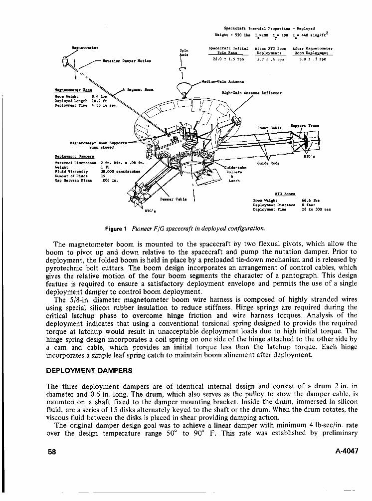
Spacecraft I n e r t i a l Propertie8 - Deployad
Weight - 550 l b s 1;ZSO I - 190 Iz- 440 s l u g / f t 2
Spacecraft I n i t i a l After RTG Boom Altar Magnetoomter
Y
Spin Rate Deployments Boom Deployment Spin A r i a
Nutation Damper Motion Qr 2 2 . 0 f 1 .5 rpm 5 . 7 ? .4 rpm 5 .0 3 . 3 rpm I
CJ
MediunrCain Antenna
Uagnatom tor Boom l loom Weight 8 . 4 Deployed Length 16.7 Deployment Time 4 t o
hgnetorater Booe Supports when s t w e d
DeDloymBnt Dampers
External Dimensions 2 i n . Dia. x .06 i n .
Fluid Vincosity 30,000 centiatok Number of Discs 15 Cap Betveen Discs .006 i n .
Weight l l b
RTC Booms llooa Weight 66.6 lbm Deployment Distance 6 f a e t Deployment Time 16 to 300 aec
Figure 1 Pioneer FIG spacecraft in deployed configuration.
The magnetometer boom is mounted to the spacecraft by two flexual pivots, which allow the boom to pivot up and down relative to the spacecraft and pump the nutation damper. Prior to deployment, the folded boom is held in place by a preloaded tie-down mechanism and is released by pyrotechnic bolt cutters. The boom design incorporates an arrangement of control cables, which gives the relative motion of the four boom segments the character of a pantograph. This design feature is required to ensure a satisfactory deployment envelope and permits the use of a single deployment damper to control boom deployment.
The 5/8-in. diameter magnetometer boom wire harness is composed of highly stranded wires using special silicon rubber insulation to reduce stiffness. Hinge springs are required during the critical latchup phase to overcome hinge friction and wire harness torques. Analysis of the deployment indicates that using a conventional torsional spring designed to provide the required torque at latchup would result in unacceptable deployment loads due to high initial torque. The hinge spring design incorporates a coil spring on one side of the hinge attached to the other side by a cam and cable, which provides an initial torque less than the latchup torque. Each hinge incorporates a simple leaf spring catch to maintain boom alinement after deployment.
DEPLOYMENT DAMPERS
The three deployment dampers are of identical internal design and consist of a drum 2 in. in diameter and 0.6 in. long. The drum, which also serves as the pulley to stow the damper cable, is mounted on a shaft fixed to the damper mounting bracket. Inside the drum, immersed in silicon fluid, are a series of 15 disks alternately keyed to the shaft or the drum. When the drum rotates, the viscous fluid between the disks is placed in shear providing damping action.
The original damper design goal was to achieve a linear damper with minimum 4 lb-sec/in. rate over the design temperature range 50" to 90" F. This rate was established by preliminary
58 A-4047
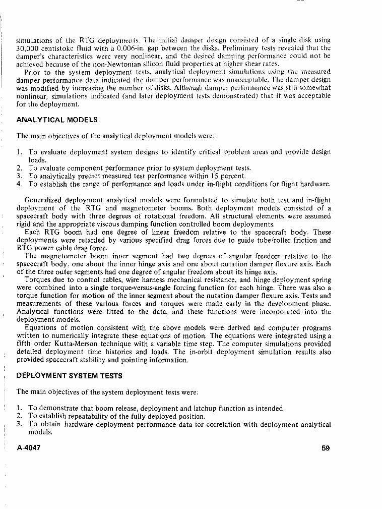
simuiations of tiit: RTG depioyrrlerits. The initial daiiipzr desigii coiiiisted of a single disk using 30,000 centistoke fluid with a 0.006-in. gap between the disks. Preliminary tests reveaied that the damper’s characteristics were very nonlinear, and the desired damping performance could not be achieved because of the non-Newtonian silicon fluid properties at higher shear rates.
Prior to the system deployment tests, analytical deployment simulations using the measured damper performance data indicated the damper performance was unacceptable. The damper design was modified by increasing the number of disks. Although damper performance was still somewhat nonlinear, simulations indicated (and later deployment tests demonstrated) that it was acceptable for the deployment.
ANALYTICAL MODELS
The main objectives of the analytical deployment models were:
1. To evaluate deployment system designs to identify critical problem areas and provide design loads.
2. To evaluate component performance prior to system deployment tests. 3. To analytically predict measured test performance within 15 percent. 4. To establish the range of performance and loads under in-flight conditions for flight hardware.
Generalized deployment analytical models were formulated to simulate both test and in-flight deployment of the RTG and magnetometer booms. Both deployment models consisted of a spacecraft body with three degrees of rotational freedom. All structural elements were assumed rigid and the appropriate viscous damping function controlled boom deployments.
Each RTG boom had one degree of linear freedom relative to the spacecraft body. These deployments were retarded by various specified drag forces due to guide tubelroller friction and RTG power cable drag force.
The magnetometer boom inner segment had two degrees of angular freedom relative to the spacecraft body, one about the inner hinge axis and one about nutation damper flexure axis. Each of the three outer segments had one degree of angular freedom about its hinge axis.
Torques due to control cables, wire harness mechanical resistance, and hinge deployment spring were combined into a single torque-versus-angle forcing function for each hinge. There was also a torque function for motion of the inner segment about the nutation damper flexure axis. Tests and measurements of these various forces and torques were made early in the development phase. Analytical functions were fitted to the data, and these functions were incorporated into the deployment models.
Equations of motion consistent with the above models were derived and computer programs written t o numerically integrate these equations of motion. The equations were integrated using a fifth order Kutta-Merson technique with a variable time step. The computer simulations provided detailed deployment time histories and loads. The in-orbit deployment simulation results also provided spacecraft stability and pointing information.
DEPLOYMENT SYSTEM TESTS
The main objectives of the system deployment tests were:
1. To demonstrate that boom release, deployment and latchup function as intended. 2. To establish repeatability of the fully deployed position. 3. T o obtain hardware deployment performance data for correlation with deployment analytical
models.
A-4047 59
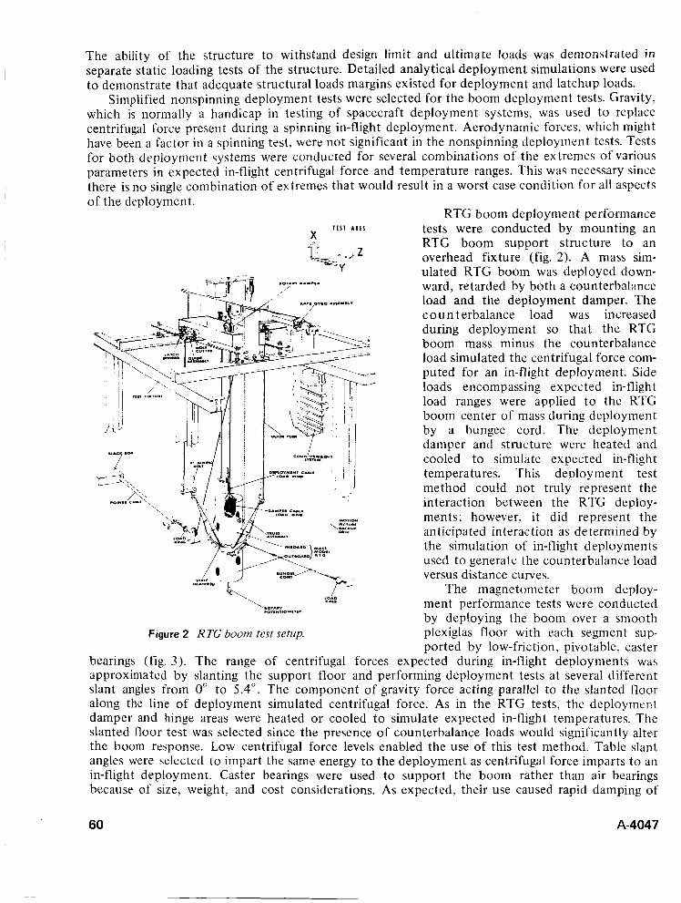
The ability of the structure to withstand design limit and ultimate loads was demonstrated in separate static loading tests of the structure. Detailed analytical deployment simulations were used to demonstrate that adequate structural loads margins existed for deployment and latchup loads.
Simplified nonspinning deployment tests were selected for the boom deployment tests. Gravity, which is normally a handicap in testing of spacecraft deployment systems, was used to replace centrifugal force present during a spinning in-flight deployment. Aerodynamic forces, which might have been a factor in a spinning test, were not significant in the nonspinning deployment tests. Tests for both deployment systems were conducted for several combinations of the extremes of various parameters in expected in-flight centrifugal force and temperature ranges. This was necessary since there is no single combination of extremes that would result in a worst case condition for all aspects of the deployment.
Figure 2 R TG boom tesr setup.
bearings (fig. 3). The range of centrifugal forces
RTG boom deployment performance tests were conducted by mounting an RTG boom support structure to an overhead fixture (fig. 2). A mass sim- ulated RTG boom was deployed down- ward, retarded by both a counterbalance load and the deployment damper. The c o u n t erbalance load was increased during deployment so that the RTG boom mass minus the counterbalance load simulated the centrifugal force com- puted for an in-flight deployment. Side loads encompassing expected in-flight load ranges were applied t o the RTG boom center of mass during deployment by a bungee cord. The deployment damper and structure were heated and cooled t o simulate expected in-flight temperatures. This deployment test method could not truly represent the interaction between the RTG deploy- ments; however, it did represent the anticipated interaction as determined by the simulation of in-flight deployments used t o generate the counterbalance load versus distance curves.
The magnetometer boom deploy- ment performance tests were conducted by deploying the boom over a smooth Plexiglas floor with each segment sup- ported by low-friction, pivotable, caster
expected during in-flight deployments waa approximated by slanting the support floor and performing deployment tests at several different slant angles from 0" to 5.4". The component of gravity force acting parallel to the slanted floor along the line of deployment simulated centrifugal force. As in the RTG tests, the deployment damper and hinge areas were heated or cooled to simulate expected in-flight temperatures. The slanted floor test was selected since the presence of counterbalance loads would significantly alter the boom response. Low centrifugal force levels enabled the use of this test method. Table slant angles were selected to impart the same energy to the deployment as centrifugal force imparts t o an in-flight deployment. Caster bearings were used to support the boom rather than air bearings because of size, weight, and cost considerations. As expected, their use caused rapid damping of
60 A-4047
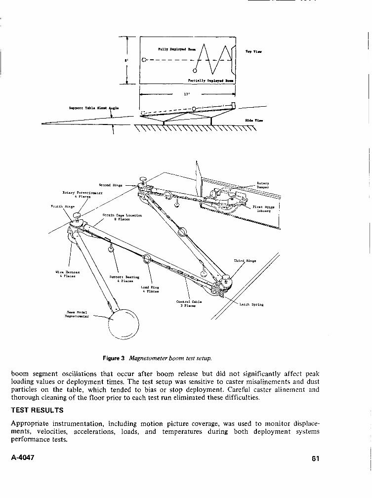
1 t i I
n Rotary Potentiome
Wire Harness SUPDort Bearing
Figure 3 Magnetometer boom test setup.
boom segment oscillations that occur after boom release but did not significantly affect peak loading values or deployment times. The test setup was sensitive to caster misalinements and dust particles on the table, which tended to bias or stop deployment. Careful caster alinement and thorough cleaning of the floor prior to each test run eliminated these difficulties.
TEST RESULTS
Appropriate instrumentation, including motion picture coverage, was used to monitor displace- ments, velocities, accelerations, loads, and temperatures during both deployment systems performance tests.
A-4047 61
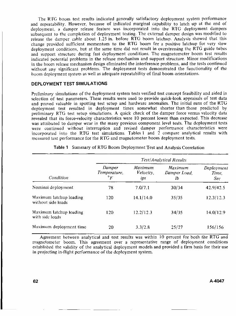
The RTG boom test results indicated generally satisfactory deployment system performance and repeatability. However, because of indicated marginal capability t o latch up at the end of deployment, a damper release feature was incorporated into the RTG deployment dampers subsequent to the completion of deployment testing. The external damper design was modified to release the damper cable about 1.25 in. before RTG boom latchup. Analysis showed that this change provided sufficient momentum to the RTG boom for a positive latchup for very slow deployment conditions, but at the same time did not result in overstressing the RTG guide tubes and support structure during fast deployment conditions. The magnetometer boom test results indicated potential problems in the release mechanism and support structure. Minor modifications in the boom release mechanism design eliminated the interference problems, and the tests continued without any significant problems. The deployment tests demonstrated the functionality of the boom deployment system as well as adequate repeatability of final boom orientations.
DEPLOYMENT TEST SIMULATIONS
Preliminary simulations of the deployment system tests verified test concept feasibility and aided in selection of test parameters. These results were used to provide quick-look appraisals of test data and proved valuable in spotting test setup and hardware anomalies. The initial runs of the RTG deployment test resulted in deployment times somewhat shorter than those predicted by preliminary RTG test setup simulations. A quick check of the damper force versus velocity data revealed that its force-velocity characteristics were 10 percent lower than expected. This decrease was attributed to damper wear in the many previous component level tests. The deployment tests were continued without interruption and revised damper performance characteristics were incorporated into the RTG test simulations. Tables 1 and 2 compare analytical results with measured test performance for the RTG and magnetometer boom deployment tests.
Table 1 Summary of RTG Boom Deployment Test and Analysis Correlation
TestlAnalytical Results
Damper Maximum Maximum Deploy men t Temperature, Yelo city, Damper Load, Time,
Con dit ion " F ips lb See
Nominal deployment 78 7.017.1 30134 42.9142.5
12.31 12.3 Maximum latchup loading 120 14.11 14.0 35/35 without side loads
Maximum latchup loading 120 12.2112.3 34/35 14.01 1 2.9 with side loads
Maximum deployment time 20 3.312.8 25/27 1561156
Agreement between analytical and test results was within 10 percent for both the RTG and magnetometer boom. This agreement over a representative range of deployment conditions established the validity of the analytical deployment models and provided a firm basis for their use in projecting in-flight performance of the deployment system.
62 A-4047

I
I I
i
~
I
i
i I
I
Tzble 2 Summiry of Magnetometer Room Deployment Test and Analysis Correlation
TestlAnalytical Results
Condition
Maximum Darnper Control M a s in? u in Deployment
Tempera tu re Loads, Damper Load, Tinze, " F lb lb Sec
Nominal deployment 78 80185 13/16 12/14
Maximum latchup loading 120 80177 14/17 719
Maximum surge loading 20 l l S / l l l 19/22 21/20
Maximum deolovment time 20 38/33 71 6 82/70
IN-FLIGHT DEPLOYMENT ANALYSES
The analytical deployment models were updated t o reflect parameter differences between the test articles and flight hardware. The RTG deployment analytical model was also modified to simulate the damper release feature incorporated into the RTG deployment system design.
hardware extremes was predicted using the analytical models. These analyses incorporated the effects of spacecraft spin rate and wobble angle. In addition, the RTG deployment analysis incorporated the interaction between RTG booms and expected differences in the deployment system parameters from boom to boom. The magnetometer boom deployment analysis incor- porated the interaction between boom deployment and boom motion about the nutation damper axis.
These results verified satisfactory deployment system performance with adequate structural margins over the range of in-flight conditions.
Iii-flight deijloyiiieiit perfomiiiiice f G i thc range of expected in-flight emirenmentz! z ~ d
CONCLUSIONS
The combined analysis and test program used to verify in-orbit deployment capability of Pioneer FIG appendages is believed to be a reliable and cost-effective technique. The approach circumvented deficiencies inherent in attempting to rely solely on either testing or analysis to provide deployment verification. The program successfully incorporated :
1. Tests of a zero-g system in a I-g environment. 2. Nonspinning tests of spinning deployment systems. 3. Tests that verified the analyses as well as hardware functionality. 4. Analyses to project final in-flight deployment systems performance over the range of hardware
and environmental extremes.
ACKNOWLEDGMENTS
The work reported in this paper was conducted at TRW Systems, Redondo Beach, Calif., under NASA Contract NAS2-5600.
A-4047 63
RADAR AUGMENTATION DEVICE
John K. Riedel Lockheed Missiles & Space Company
Sunnyvale, California
ABSTRACT. The radar augmentation device (RAD) serves to increase the radar response of a target body and thus expedite radar acquisition. This paper discusses the design and development of the RAD, with particular emphasis on technical problems that were encountered and solved. Also included are discussions of the mode of operation of the R-AD and the groiund test history.
INTRODUCTION
Over age Polaris missiles are being used as targets in the evaluation of radar effectiveness for the Safeguard program. To assure early acquisition of the Polaris reentry body (REB), i t was necessary to increase or augment its radar response to guarantee a given level of radar cross section (RCS) when viewed from any aspect. To meet this requirement, it was decided to use an inflatable sphere, which would be attached or tethered to the REB. Electromagnetic analyses established that a reflective sphere of 8 ft diameter would provide the required response and still account for electromagnetic losses. The unique requirement was that the RAD be deployed from, and tethered to, an off-center position of a spinning and precessing body. This design requirement imposed adverse dynamic loads on the sphere both during and after its deployment and inflation.
RAD DESIGN
Figures 1 , 2, and 3 show the RAD in the stowed and fully deployed configurations. The main component of the RAD assembly is the radar reflector, an 8-ft diameter inflatable sphere, made of a tri-ply mylar-aluminum-mylar laminate. Twenty-four gores are cemented together with two polar caps to provide the spherical shape. It contains a central inflation tube through which the inflating medium, Freon 22, is introduced into the sphere. The base of the sphere is cemented t o the inflation tube, which in turn is cemented t o the base of the tether. The tether is a rigid, hollow, Fiberglass cylinder that attaches the sphere t o the RAD canister and, when extended by a volute spring, holds it away from the hot damaging surfaces of the REB. When the sphere is deployed and inflated, four Nomex (high-temperature nylon) shroud lines provide the stability necessary to withstand REB dynamics. In the stowed position, the sphere is folded into the tether, which telescopes into the aluminum RAD canister, the main structural component. The canister is fastened to the REB by three 1 /4-in. diameter screws. It supports the stainless steel Freon reservoir and the aluminum valve housing through which Freon is transferred from the reservoir into the canister and on into the sphere. The valve housing contains a spring-loaded steel piercer, which punctures the stainless steel diaphragm to release the Freon when the RAD is initiated. The diaphragm is silver soldered to the outlet of the Freon bottle. The RAD initiator is a standard reefing line cutter modified to provide 30 sec of time delay. It is clamped to the RAD canister and is initiated by the pull of a lanyard at REB separation. (The lanyard is not part of the RAD assembly.) The design also incorporates thermal protection provisions for the RAD.
The RAD pyro timer is initiated a t the time the body is ejected from the missile. The sequence of operation of the RAD is given in figure 2, from initiation to full inflation of the sphere.
A-4047 65

FOLDED
COVER HINGE I \ \ \ I I // / VOLUTE SPRING
STANDOFF
/ ‘SPACER \ ‘TETHER \ \VOLUTE SPRING
COVER LATCH’ (PINNED WITH PRIMER)
\TIMER AND THERMAL SHROUD
Figure 1 Radar augmentation device stowed.
I. LANYARD PULLS SPHERE INFLATES SEAR IN TIMER FULLY
2. TIMER PROVIDES IO. SHROUD LINES 30-sec DELAY AND DEPLOY, BECOME SHEARS PIN, TAUT RELEASES SWITCH
9. FREON REVERSES CONE, UNFOLDS
3. RAD LID SPRINGS SPHERE OPEN
8. FREON FLOWS THRU ORIFICE INTO INFLATION TUBE, TETHER. START OF
SPHERE EXPULSION EXPELS SPHERE
Z FREON TRANSFERS TO CANISTER AND
4. VOLUTE SPRING EXTENDS
/ VAPORIZES
DIAPHRAGM
5. VALVE LINKAGE IS RELEASED ‘6. PIERCER PUNCTURES
Figure 2 Radar augmentation device deployed; sequence of operation.
66 A-4047

KAPTON REINFORCEMENT
SHROUD LINE
CRITICAL GORES-(4) MADE OF 24 GORES
L AMlN AT E
RE INFO RC E D WITH K A P TON MYLAR-ALUM-MYLAR
Figure 3 Radar augmentation device deployed.
DESIGN EVOLUTION
Deployment of the RAD from an off-center position of a spinning and precessing body presente, I a very sensitive design problem. In effect, the ultimate design had to achieve a compromise between two physical problem areas wherein a consistent operating band could be established. If inflation were accomplished too rapidly, excessive sphere stresses would result, but if inflation were too slow, the sphere would tangle and wrap up with the spinning body.
While the importance of controlling these design factors was recognized early in the program, the development difficulties that were to be encountered were not fully appreciated a t that time. A more or less chronological discussion of the problems encountered is given below.
Freon Transfer System From analysis and tests conducted early in the development program, an optimum time of about 2 sec was established for deployment and inflation of the 8-ft sphere. Tests conducted in the conceptual stage of the program demonstrated that this rapid inflation rate could not be achieved with the original design because the Freon transfer system restricted flow of the inflating medium. Unlike the final design, in which the Freon was released directly into the RAD canister, the original design utilized small-diameter lines to transfer Freon into the sphere (fig. 4). These lines provided a restricted flow path, which analysis indicated could not transfer the Freon rapidly enough unless they were enlarged considerably. Existing volume constraints made this a difficult solution, and therefore the present transfer system was adopted into the design. This redesign also incorporated a spring-loaded piston inside the Freon reservoir to provide a positive or forced flow of liquid Freon into the RAD canister and thus yield a maximum mass flow of Freon. A small amount of Freon also was introduced against the back side of the piston to balance the vapor pressure acting on the front side, minimizing Freon leakage by the piston O-rings. As an added precaution, a charge of 25 psi of nitrogen gas was added behind the piston to aid the spring in overcoming the higher static friction that might occur from long-term O-ring set.
During this period the piercer design was changed from a dart to a hollow tube style which allowed a transfer of Freon through the piercer, rather than around it. This change was introduced
A-4047 67

MECHANICAL TIMER /INFLATION TUBE \
DART PIERCER -ONE SPRING
F22 BOTTLE
DISPLACEMENT) (NoN-POSITIVE
/ INTERNAL FLEXl6LE INFLATANT LINE LINE
NEW INFLATION TUBE AND DIFFUSER
F22 FLOW THROTTLE0 AT TETUER BASE
UOLLOW TUBE GUIDED PIERCER - T W O SPRINGS
VOLUTE SPRING
PRESSURIZED SEALED CANISTER (ALL INFLATANT LINES ELIMINATED)
I Figure 4 Freon transfer system.
following a functional test at elevated temperature wherein the higher vapor pressure of the Freon created by the elevated temperature (95" F ) acted on the point and shoulder of the dart piercer as soon as it started to puncture the diaphragm, forcing the piercer back before full penetration was achieved. The truncated hollow tubular, piercer, selected from several alternate candidates, circumvented this mode of failure, but led to another one: In a subsequent test there was virtually no transfer of Freon, and dissection of the hardware showed that the tab in the diaphragm, which formed when it was punctured, lay over the end of the hollow piercer thus blocking the flow of Freon. A center post inside the hollow piercer was added to preclude blockage by the tab; also several bypass holes were added so that Freon flow could still occur even if the end of the piercer became obstructed.
Inflatable Sphere The analysis suggested that Freon should be dumped into the sphere as rapidly as possible. However, in the first test of the new system, which incorporated a large (I-in. diameter) opening or orifice to provide maximal mass transfer of liquid Freon into the sphere, the sphere ruptured violently just as full inflation was being achieved. The inflation tube (fig. 3) was torn loose from the tether base, and the sphere was ripped open its full length.
A series of bench tests and full-scale deployment/inflation tests were conducted to measure and optimize the Freon flow rate; also, the design of the inflation tube and its attachment point of the sphere was improved. During these tests, the orifice size became progressively smaller (down to 0.047-in. diameter) to provide less strenuous and more reliable deployment of the sphere. In most tests, the sphere survived; however, there were occasional failures, and close post-test examination of the spheres often showed small slits and pin holes, which indicated stressing of the sphere skin.
68 A-4047
Lcm! rehforcernent was incorporated into the sphere, but this measure hampered the packing of tlie sphere into the limited volume of the tether and canister. I t became increasingly apparent that changes would have to be introduced to alleviate the high packing factor of the stowed sphere. Forces as high as 1200 lb compression were being used to fold the sphere into the tether. Therefore, a decision was made to lengthen the canister from about 10 to about 14 in. This new design with the lengthened canister was successfully tested once, but in a second test, which was supposed to represent the final development test, the sphere started to inflate before it was fully expelled from the tether. The partially inflated sphere then twisted (it tended to remain fixed while the fixture kept on spinning) and then rapidly untwisted just as full expulsion and inflation were being achieved. These combined dynamics overstressed the sphere, and it ruptured. I t was postulated that with the increased container volume, the bottom folds were not folded as tightly as previously, thus allowing an early flow of Freon into the sphere and a momentary delay in the expulsion of the sphere, which produced the premature inflation and rupture.
Following this failure, folding procedures were revised to provide better controlled and more precise folds. Also, a reversible cone was incorporated inside the inflation tube just beyond the mouth of the tether. The cone is made of a thin fiim of myiar and is open at both top aiid bottom; it is glued to the inside of the inflation tube, and the Freon must pass through it enroute to the sphere. In application, it is folded back on itself - reversed - and in this position it momentarily blocks the flow of Freon'vapor until sufficient pressure builds up to turn the cone right side out, pressurizing the base of the inflation tube and forcing it and the sphere out of the tether before any significant inflation of the downstream portion can occur. Figure 2 shows the cone in the deployed position.
Orientation Sensitivity For an evaluation of these improvements unbiased by the influence of gravity, the unit was mounted horizontally in a deployment test as shown in figure 5. While there was marked improvement in expulsion performance, there was a pronounced slowdown in inflation rate. Subsequent investigation established that with the horizontal orientation, Freon flowed through the orifice and into the sphere in a gaseous state; with the fixture inclined downward, as in previous tests, the Freon cendense.1, 2nd puddled 1.y a t the bottom of the canister, and drained through the orifice and into the sphere in a liquid state, thus providing a significantly larger mass flow of Freon and a correspondingly faster rate of inflation. The design was thus shown to be orientation sensitive, and since RAD orientation was random at time of deployment, the nature of the flow (whether vapor or liquid), and therefore the rate of inflation, was unpredictable and unreliable. To correct this, the design was changed to incorporate a standpipe located centrally in the tether base. The orifice was placed at the top of this standpipe, above the level of liquid that would accumulate in the canister, thus assuring only vapor flow through it.,
A series of tests was then conducted t o determine the proper size of the vapor orifice. Since the orifice was now designed to transmit only vapor rather than liquid, a larger size was required; 0.170-in. diameter was selected on the basis of test results.
Shroud Lines Figure 3 shows that the final design incorporates four shroud lines t o provide stability for the inflated sphere against the motion dynamics imparted by the Polaris REB. The original design incorporated 24 shroud lines attached to a skirt, which in turn was bonded circumferentially around the sphere at the point or circle of tangency., The skirt and the lines complicated both packaging and deployment of the sphere. In a deployment test designed to confirm the orifice redesign, the sphere became tangled in the lines during initial deployment, and ruptured. In a subsequent experimental test, the lines were eliminated entirely, and while the sphere survived initial deployment and inflation, it lost stability under the spin dynamics and failed, tearing at the throat. The throat area was reinforced with a fabric/mylar polar cap, and the four-line design was instituted. Since the four lines could not provide the stability obtained with 24 lines, they were
A-4047 69

OR IGI N AL
SLOW INFLATION
VAPOR
SPHERE I \ I
‘ F22 LIQUID OR
FAST IN FL AT I ON f
REVISED
CONS1 STENT
STANDPIPE WITH SPHERE VAPOR ORIFICE
SPHERE
Figure 5 Orientation sensitivity.
“cinched up” that is, shortened. This produced yet another mode of failure: The shortening promoted the formation of a gooseneck, or kink, in the sphere as it snaked out of the tether. The gooseneck then evolved into a restriction about which the deploying sphere twisted and then burst. This problem was solved by using less shortening and employing a shift fold in the sphere t o take up the excess material (fig. 6).
Additional Orifice Sizing Following the corrective action described above, seven tests were conducted to establish confidence in the RAD reliability. Six of the tests were successful, and one was only partially successful. In this test a 6-in. by 10-in. hole appeared just as full inflation was achieved, and the sphere deflated in about 30 sec. Several refinements were introduced in the sphere-packaging procedures to provide further confidence, and the RAD was committed to production. Three production assessment tests were conducted. The first two were successful, but in the final test a failure occurred similar t o the one above. Accordingly, additional development tests were conducted, and the orifice size was reduced further to slow the rate of inflation, permitting a gentler and more orderly unfolding of the sphere during deployment and initial inflation. Several iterations were required to bring the orifice to its present size (0.093 in.). While slower inflation permitted a greater degree of twisting of the sphere during initial inflation, it was not enough to produce a restriction and subsequent rupture seen in earlier tests with the 24-line design. The greater tolerance for slower inflation apparently was enhanced by the removal of the skirt (part of the 24-line configuration), since this skirt tended to act as a belt, forming a momentary restriction during initial inflation.
The final design was proven in ten consecutive successful dynamic deployment tests in the vacuum chamber and has since been successfully flight tested in the Safeguard program.
70 A-4047
ec PRESHORTENEO LINES
FOLDED SPHERE
PRESHORTENED LINES
TUCK-UNDER FOLD*
FOLDED SPHERE
rYR/CAC &UCC€$SFql U € ~ O Y M € U t
*TUCK-UNDER ( OR SWIFT) FOLD MADE BEFORE PLEAT (OR LONGITUDINAL) FOLDS ARE MADE
Figure 6 Sphere problem.
CONCLUSIONS
The RAD provides a device that not only satisfied all design requirements, but also exceeded expectations when used in a flight test to evaluate target based radars. The RAD development proved t o be more difficult than originally anticipated. The most difficult problem derived from the requirement to tether the RAD to the spinning and precessing REB and to deploy it from a completely random orientation. This is the only known application of deploying a large self-inflating sphere in such a manner. In addition, the attention given to the electromagnetic design aspects yielded a target that provided a much steadier (nonscintillating) radar return than that obtained from inflatable devices used in the past. With the knowledge and techniques developed during this program it would be possible to augment and even disguise the radar signature of any target during exoatmospheric flight, regardless of its motion dynamics.
ACKNOWLEDGMENTS
Developed under prime contract No. N0003068c0303 by G. T. Schjeldahl Company, Northfield, Minnesota, under subcontract t o Lockheed Missiles & Space Company.
A-4047 71
DISCUSSION Leonard L. Spangler: How are the sections of the RAD sphere joined'?
A-4047
Author: The basic sphere comprises 24 gores (sections) and two 15-in.-diameter polar caps all bonded together with GT 201 Schjeldahl adhesive. The gore seams are butt joints with an overlay of 1-in. wide adhesive tape, made of the same laminate as the basic sphere.
Six of the gore seams, which carry a higher load during initial unfolding and inflation, also have an overlay of adhesive tape on the inside of the sphere. The butt joints have a 1/16-in. gap between adjacent gores to provide optimal electromagnetic continuity. The seams a t the polar caps are overlapping joints with an overlay of adhesive tape.
Leonard L. Spangler: Did creases occur in the Kapton film during stowage of the RAD sphere?
Author: Kapton is bonded over the basic mylar-aluminum-mylar laminate in certain areas of the sphere for thermal protection and reinforcement. It was not found t o be any more sensitive to creasing than the basic laminate. The amount of inflating gas (Freon 22) was selected to load or stress the skin to give as smooth a surface as possible to provide optimum radar reflectivity. In the inflated condition, the balloon is very smooth and spherical. At the seams, however, there are slight wrinkles or ripples. On deflation, residual creases are evident at the fold lines.
C. R. Bumstead: Why not use a corner reflector or a Luneberg lens?
Author: In flight the reentry body (REB) to which the RAD is attached or tethered has a random motion due t o its spin and nutation; thus it, and anything attached t o it, presents a constantly changing aspect t o the examining radar. Therefore, the reflector of the RAD had t o be insensitive t o aspect of the radar. It was also required to maintain a given level of radar cross section virtually continuously 90 percent of the time. Lastly, the RAD has t o be consumed during reentry. The corner reflector could not satisfy these requirements. Further, the RAD had to be stowable in a small volume inside the REB and deployed in flight. The Luneberg lens, being made of dielectric materials, cannot be made t o be deployable in flight. An inflatable sphere best satisfied all the performance and design requirements.
72
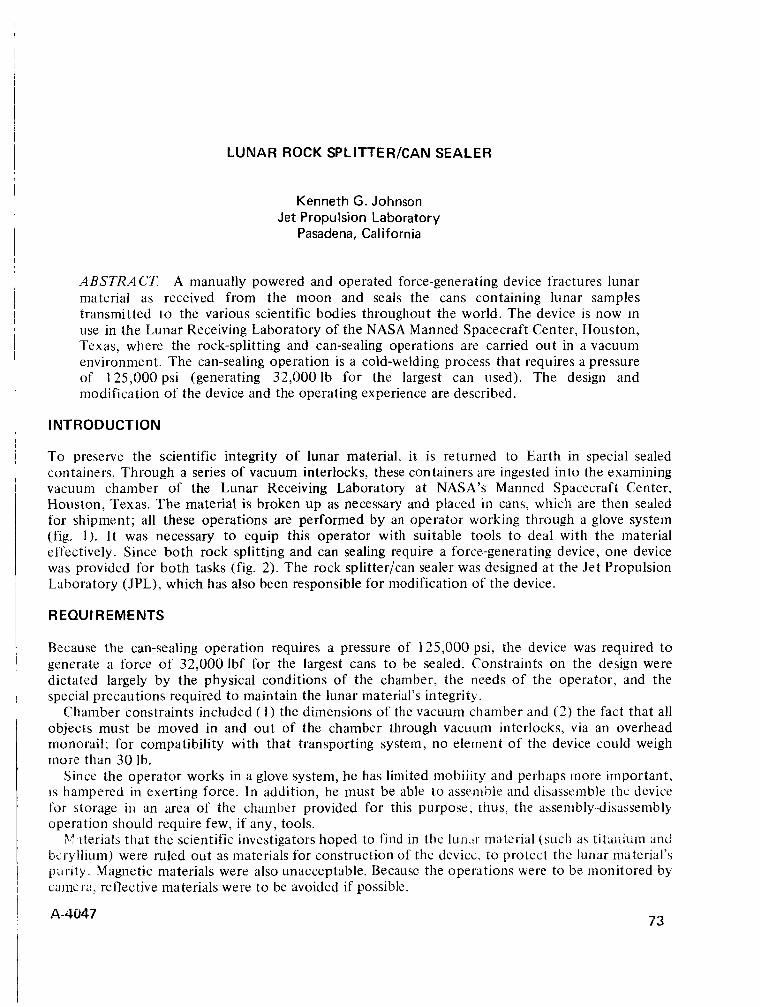
LUNAR ROCK SPLITTERKAN SEALER
Kenneth G. Johnson Jet Propulsion Laboratory
Pasadena, California
ABSTRACT A manually powered and operated force-generating device fractures lunar material as received from the moon and seals the cans containing lunar samples transmitted t o the various scientific bodies throughout the world. The device is now in use in the Lunar Receiving Laboratory of the NASA Manned Spacecraft Center, Houston, Texas, where the rock-splitting and can-sealing operations are carried out in a vacuum environment. The can-sealing operation is a cold-welding process that requires a pressure of 125,000 psi (generating 32,0001b for the largest can used). The design and modification of the device and the operating experience are described.
INTRODUCTION
To preserve the scientific integrity of lunar material, it is returned to Earth in special sealed containers. Through a series of vacuum interlocks, these containers are ingested into the examining vacuum chamber of the Lunar Receiving Laboratory at NASA’s Manned Spacecraft Center, Houston, Texas. The material is broken u p as necessary and placed in cans, which are then sealed for shipment; all these operations are performed by an operator working through a glove system (fig. 1). It was necessary to equip this operator with suitable tools t o deal with the material effectively. Since both rock splitting and can sealing require a force-generating device, one device was provided for both tasks (fig. 2). The rock splitter/can sealer was designed a t the Jet Propulsion Laboratory (JPL), which has also been responsible for modification of the device.
R EQU I R EME NTS
Because the can-sealing operation requires a pressure of 125,000 psi, the device was required to generate a force of 32,000 lbf for the largest cans to be sealed. Constraints on the design were dictated largely by the physical conditions of the chamber, the needs of the operator, and the special precautions required to maintain the lunar material’s integrity.
Chamber constraints included ( 1 ) the dimensions of the vacuum chamber and (2) the fact that all objects must be moved in arid out of the chamber through vacuum interlocks, via an overhead monorail; for compatibility with that transporting system, no element of the device could weigh more than 30 Ib.
Since the operator works in a glove system, he has limited mobiiity and perhaps more important, i s hampered in exerting force. In addition, he must be able to assemble and disassemble he device for storage i t i an area of the chamber provided for this purpose; thus, the assenib1y.-disassembly operation should require few, if any, tools.
34’ tterials that the scientific investigators hoped to find in the 1uri.~r material (such as titaiiiuln and Licrylliuin) were ruled out as materials for construction of the device. to protect the lunar material’s parity. Magnetic materials were also unacceptable. Because the operations were to be monitored by cams I:!, reflective materials were to be avoided if possible.
73 A-4047
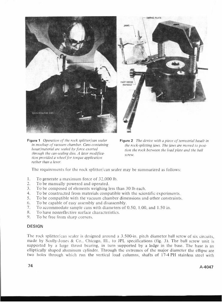
Figure 1 Operation of the rock splitterfcan sealer Figure 2 The device with a piece of terrestrial basalt in in mockup of vacuum chamber. Cans containing lunarfmaterial are sealed by force exerted through the can-sealing dies. A later modifica- tion provided a wheel for torque application rather than a lever.
the rock-splitting jaws. The jaws are moved to posi- tion the rock between the load plate and the ball screw.
The requirements for the rock splitter/can sealer may be summarized as follows:
1. 2. 3. 4. 5. 6. 7. 8. 9.
To generate a maximum force of 32,000 Ib. To be manually powered and operated. To be composed of elements weighing less than 30 lb each. To be constructed from materials compatible with the scientific experiments. To be compatible with the vacuum chamber dimensions and other constraints. To be capable of easy assembly and disassembly. To accommodate sample cans with diameters of 0.50, 1.00, and 1.50 in. To have nonreflective surface characteristics. To be free from sharp corners.
DESIGN
The rock splitter/can sealer is designed around a 3.500-in. pitch diameter ball screw of six circuits, made by Scully-Jones & Co., Chicago, Ill., t o JPL specifications (fig. 3). The ball screw unit is supported by a large thrust bearing, in turn supported by a ledge in the base. The base is an elliptically shaped aluminum cylinder. Through the extremes of the major diameter the ellipse are two holes through which run the vertical load columns, shafts of 17-4PH stainless steel with
74 A-4047

castellated lands that mate with corresponding femaie-type mem- bers. The female-type bushings are secured to an aluminium load plate, which completes the force loop. The castellated lands of the load columns allow adjustment of the !oad =!ate to accommodate the anticipated range of sizes of both the lunar material and cans for sealing.
The nut of the ball screw unit r o t a t e s and receives the input torque through a one-stage gear reduction whose pinion is driven by a ratcheted lever on a torque- input wheel in the hands of the operator. The screw portion of the unit is contained against rotation by means of a cam fol-
Figure 3 Components of the rock splitterlcan sealer. lower riding in a groove and mounted in the base. The empir- ically determined efficiency of a ball screw unit is 95%.
The relation of input torque to output force is: E = PL/27iT
where
Efficiency E = work out/work in
Work out = force exerted by the unit times the distance it travels for one revolution L = lead of ball screw unit of the nut
P = force
T = torque
E = efficiency Work in = input energy for one revolu-
tion of the nut
Rearranging terms gives
which relates input torque to output force. To determine the mechanical advantage, let
K = radius of lever N, = number of teeth of pinion
N, = number of teeth of gear F = force generated by operator
Then the input torque to the ball screw unit is
T = F R ( N , / N , )
A-4047 75
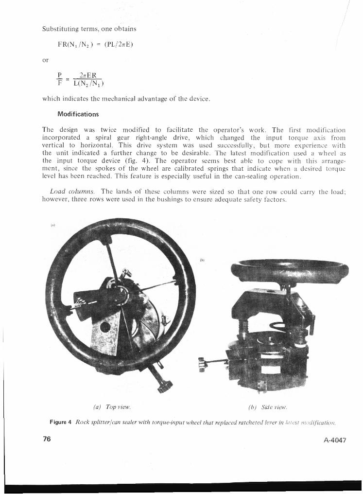
Substituting terms, one obtains
FR(N, /N, ) = (PL/2nE)
or
which indicates the mechanical advantage of the device.
Modifications
The design was twice modified to facilitate the operator’s work. The first modification incorporated a spiral gear right-angle drive, which changed the input torque axis from vertical to horizontal. This drive system was used successfully, but more experience with the unit indicated a further change to be desirable. The latest modification used a wheel as the input torque device (fig. 4). The operator seems best able to cope with this arrange- ment, since the spokes of the wheel are calibrated springs that indicate when a desired torque level has been reached. This feature is especially useful in the can-sealing operation.
Load columns. The lands of these columns were sized so that one row could carry the load; however, three rows were used in the bushings to ensure adequate safety factors.
( a ) Topview. ( b ) Side view.
Figure 4 Rock splitterlcan sealer with torque-input wheel that replaced ratcheted lever it1 h ~ : ~ ~ s ~ niotlificatioti.
76 A-4047

Figure 5 Beam deflection diagram of the load plate.
ACKNOWLEDGEMENTS
Loud phir . Figure 5 gives a strcss-defle c t ' ion L I I ~ L evaluates the sticzgth of t he !=ad
plate, showing the maximum anticipated stress to be 14.7 kpsi at a deflection of 0.0094 in. Thus while sealing cans, the device stores a sub- stantial amount of energy which must be safely released by gradually relaxing the load in a con- trolled manner.
c.* i;v e c1- - c
Ratchet. The ratchet controlling the main drive gear is actually a gear sector that is not free to rotate about its own center but must oscillate about a pivot. The geometry is such that the line of action between these gears pro- duces a torque that ensures positive engagement of the ratchet. The ratchet is equipped with a detent override, which is used in the previously mentioned relaxation process.
Jaws. The rock-splitting jaws are wedge- shaped, removable elements, whose cutting edges are tool bits clamped in place.
Dies. The can-sealing dies were speciaiiy ground [sets] for each size of can. The can- sealing operation was augmented by a swing plate which helped in the loading and position- ing of the cans.
Lubrication. Lubrication for the device was MoSz, applied dry and lightly coated by hand.
CONCLUSIONS
The rock splitterlcan sealer was overhauled and refinished after each Apollo mission. JPL has been involved in these overhauls and thus has been able to observe the wear and tear. One cam follower failed because lunar dust filtered between the bearing surfaces. The cam follower was slightly redesigned and replaced. There has been no structural damage, and the gear, pinion, ratchet, and ball screw continue to perform satisfactorily.
The author wishes to acknowledge the substantial contributions of these JPL staff members who were immediately connected with this project: Douglas Nash, Robert Keskinen, Marion Beers, Gilbert Bastien, and Robert W. Fuller. The research outlined in this paper was carried out at the Jet Propulsion Laboratory, California Institute of Technology, under Contract No. NAS 7-1 00, sponsored by the National Aeronautics and Space Administration.
A-4047 77
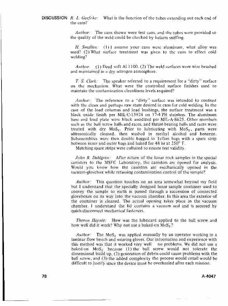
DISCUSSION R. L. Guefcke: What is the function of the tubes extending out each end of the cans‘?
Author: The cans shown were test cans, and the tubes were provided so the quality of the weld could be checked by helium sniffing.
H. Smallen: ( 1 ) I assume your cans were aluminum, what alloy was used? (2) What surface treatment was given to the cans to effect cold welding?
Author: ( 1 ) Dead soft A1 1 100. (2) The weld surfaces were wire brushed and maintained in a dry nitrogen atmosphere.
T. S. Clark: The speaker referred t o a requirement for a “dirty” surface on the mechanism. What were the controlled surface finishes used to maintain the contamination cleanliness levels required?
Author: The reference t o a “dirty” surface was intended to contrast with the clean and perhaps raw state desired in cans for cold welding. In the case of the load columns and load bushings, the surface treatment was a black oxide finish per MIL-C-13924 on 17-4 PH stainless. The aluminum base and load plate were black anodized per MIL-A-8625. Other members such as the ball screw balls and races, and thrust-bearing balls and races were treated with dry MoS,. Prior to lubricating with MoS,, parts were ultrasonically cleaned, then washed in methyl alcohol and benzene. Subassemblies were then double bagged in Teflon bags with a spare strip between inner and outer bags and baked for 48 hr at 250” F.
Matching spare strips were cultured t o ensure test validity.
John B. Duhlgren: After return of the lunar rock samples in the special canisters to the MSFC Laboratory, the canisters are opened for analysis. Would you know how the canisters are mechanically opened in the vacuum-glovebox while retaining contamination control of the sample?
Author: This question touches on an area somewhat beyond my field but I understand that the specially designed lunar sample container used t o convey the sample to earth is passed through a succession of connected gloveboxes on its way into the vacuum chamber. In this area the exterior of the container is cleaned. The actual opening takes place in the vacuum chamber. I understand the lid contains a vacuum seal and is secured by quick-disconnect mechanical fasteners.
Theron Huynie: How was the lubricant applied t o the ball screw and how well did it work? Why not use a baked-on MoSz?
Author: The MoS, was applied manually by an operator working in a laminar flow bench and wearing gloves. Our information and experience with this method was that it worked very well - no problems. We did not use a baked-on MoS, because ( 1 ) the ball screw would not tolerate the dimensional build up, (2) generation of debris could cause problems with the ball screw, and (3) the added complexity the process would entail would be difficult t o justify since the device must be overhauled after each mission.
78 A-4047

Roy -,%.I. - 4 r k ~ r : applying pressure?
Did you crimp the edges of the can in addition to
Author: The sealing of the cans was accomplished solely by pressure without crimping.
I A-4047
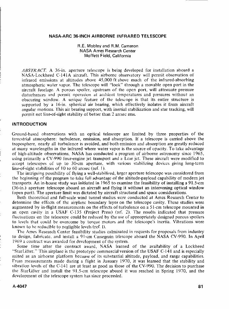
NASA-ARC 36-1 NCH AI RBORN E I N F RARE D TE LESCOPE
R.E. Mobley and R.M. Cameron NASA Ames Research Center
Moffett Field, California
ABSTRACT. A 36-in. aperture telescope is being developed for installation aboard a NASA-Lockheed C-14 1 A aircraft. This airborne observatory will permit observation of infrared emissions at altitudes above 45,000 f t above much of the infrared-absorbing atmospheric water vapor. The telescope will “look” through a movable open port in the aircraft fuselage. A porous spoiler, upstream of the open port, will attenuate pressure disturbances and permit operaiion a i aliibieiii temperatures afid pressures withnut an obscuring window. A unique feature of the telescope is that its entire structure is supported by a 16-in. spherical air bearing, which effectively isolates it from aircraft angular motions. This air bearing support, with inertial stabilization and star tracking, will permit net line-of-sight stability of better than 2 arcsec rms.
INTRODUCTION
Ground-based observations with an optical telescope are limited by three properties of the terrestrial atmosphere: turbulence, emission, and absorption. If a telescope is carried above the troposphere, nearly all turbulence is avoided, and both emission and absorption are greatly reduced at many wavelengths in the infrared where water vapor is the source of opacity. To take advantage of high-altitude observations, NASA has conducted a program of airborne astronomy since 1965, using primarily a CV-990 four-engine jet transport and a Lear jet. These aircraft were modified to accept telescopes of up t o 30-cm aperture, with various stabilizing devices giving long-term line-of-sight stabilities of 10 to 60 arcsec (ref. I ) .
The intriguing possibility of flying a well-stabilized, larger aperture telescope was considered from the beginning of the program to take full advantage of the altitude-payload capability of modern jet transports. An in-house study was initiated in 1965 to examine the feasibility of installing a 91.5-cm (36-in.) aperture telescope aboard an aircraft and flying it without an intervening optical window (open port). The aperture limit was dictated by aircraft structural and space considerations.
Both theoretical and full-scale wind tunnel studies were conducted at Ames Research Center to determine the effects of the airplane boundary layer on the telescope cavity. These studies were augmented by in-flight measurements on the effects of turbulence on a 5 I-cm telescope mounted in an open cavity in a USAF C-135 (Project Press) (ref. 2). The results indicated that pressure fluctuations on the telescope could be reduced by the use of appropriately designed porous spoilers to levels that could be overcome by torque motors and the telescope’s inertia. Vibrations were known to be reducible to negligible levels (ref. 1).
The Ames Research Center feasibility studies culminated in requests for proposals from industry to design, fabricate, and install a 91-cm Cassegrain telescope aboard the NASA CV-990. In April 1969 a contract was awarded for development of the system.
Some time after the contract award, NASA learned of the availability of a Lockheed “StarLifter.” This airplane is the prototype commercial version of the USAF C-141 and is especially suited as an airborne platform because of its substantial altitude, payload, and range capabilities. From measurements made during a flight in January 1970, it was learned that the stability and vibration levels of the C-141 are at least as good as those of the CV-990. The decision to purchase the StarLifter and install the 91.5-cm telescope aboard it was reached in Spring 1970, and the development of the telescope system has since proceeded.
A-4047 81
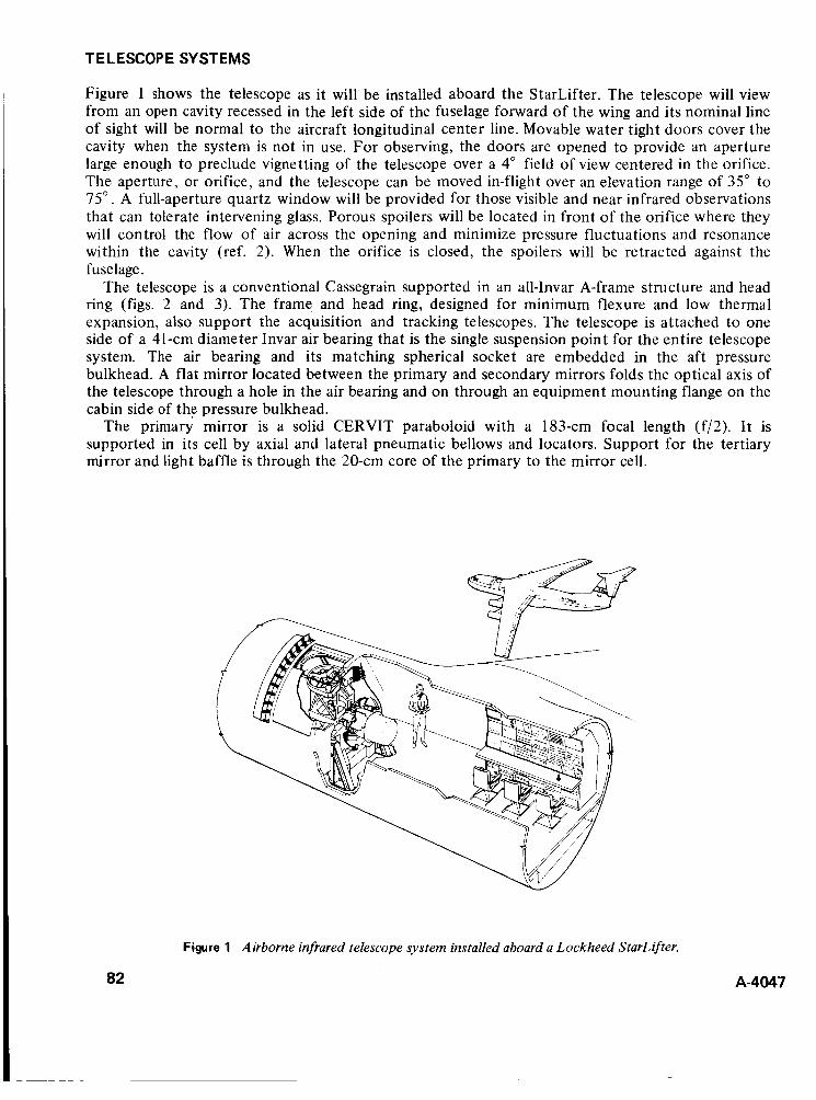
TELESCOPE SYSTEMS
Figure 1 shows the telescope as it will be installed aboard the StarLifter. The telescope will view from an open cavity recessed in the left side of the fuselage forward of the wing and its nominal line of sight will be normal to the aircraft longitudinal center line. Movable water tight doors cover the cavity when the system is not in use. For observing, the doors are opened to provide an aperture large enough to preclude vignetting of the telescope over a 4" field of view centered in the orifice. The aperture, or orifice, and the telescope can be moved in-flight over an elevation range of 35" to 75". A full-aperture quartz window will be provided for those visible and near infrared observations that can tolerate intervening glass. Porous spoilers will be located in front of the orifice where they will control the flow of air across the opening and minimize pressure fluctuations and resonance within the cavity (ref. 2). When the orifice is closed, the spoilers will be retracted against the fuselage.
The telescope is a conventional Cassegrain supported in an all-Invar A-frame structure and head ring (figs. 2 and 3). The frame and head ring, designed for minimum flexure and low thermal expansion, also support the acquisition and tracking telescopes. The telescope is attached to one side of a 41-cm diameter Invar air bearing that is the single suspension point for the entire telescope system. The air bearing and its matching spherical socket are embedded in the aft pressure bulkhead. A flat mirror located between the primary and secondary mirrors folds the optical axis of the telescope through a hole in the air bearing and on through an equipment mounting flange on the cabin side of the pressure bulkhead.
The primary mirror is a solid CERVIT paraboloid with a 183-cm focal length (f/2). It is supported in its cell by axial and lateral pneumatic bellows and locators. Support for the tertiary mirror and light baffle is through the 20-cm core of the primary to the mirror cell.
82
Figure 1 Airborne infrared telescope system installed aboard a Lockheed StarLifter.
A-4047

TRACK11 WIRE CURTAIN TELESC
FWD 3 NG ACQUISITION OPE TELESCOPE , SPOILER
LINE OF SGHT
-0CKING BRAKE
TERTIARY MIRROR
'q OPTIMUM FOCAL POINT - NORMAL
CASSEGRAIN
ELEVATION TOROUER
SPHERICAL AIR BEARING
Figure 2 Outboard view of the telescope installation.
40" * MOVABLE SHIELD OBSERVATION
DISSECTOR IMffiE u Figure 3 Forward view of the telescope installation.
The secondary mirror, also of solid CERVIT, is a 23-cm diameter hyperboloid. It will be figured to yield an overall focal ratio of f/ 13.5 ( 12.3m) at final focus. The mirror and step-focus drive are held in the head ring by an orthogonal Invar spider. Some types of radiometry and photometry employ a wobbling secondary mirror as an efficient means of space filtering. Accordingly, an alternate secondary assembly will be provided that can be oscillated at frequencies up to 140 Hz.
In the folded mode, optimum focus will fall 61-cm from the mounting flange on the cabin side of the air bearing. Total back-focus will be 76 cm. The hole in the flange (fig. 4) contains a disk that can be rotated to five positions interposing different pressure-carrying infrared or visible transmitting windows. With one of the pressure windows in the optical path, instruments can be operated in the cabin environment. With the window removed, the detector package can be operated in the cavity environment, provided a pressure vessel (supplied with the telescope) is installed around the detector package or the detector package itself is designed t o carry the pressure differential (0.56 atm). A failsafe interlock will prevent rotating the disk across the open-hole position when a pressure differential exists.
A-4047 83
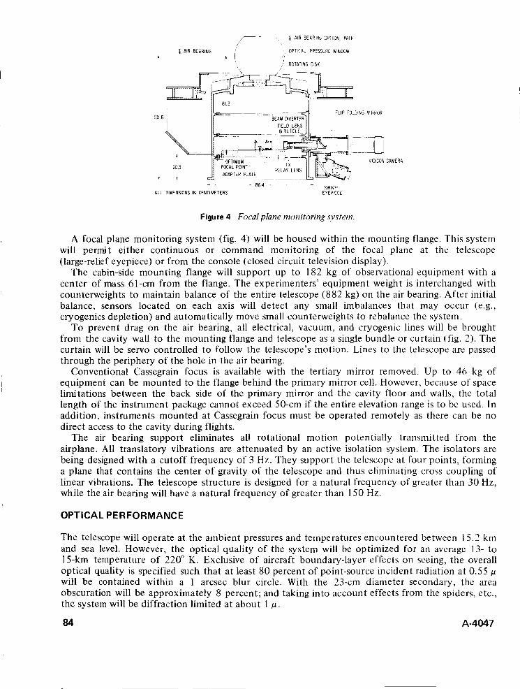
[ AIR BEARING OPTICAL PATH
[ AIR BEARING OPTICAL PRESSURE WINDOW 4
ROTATING DISK
IO1 6
I
FLIP FOLDING MIRROR
ADAPTER PLATE ~~~~
VIDICON CAMERA
- - SWIVEL 86 4
ALL DIMENSIONS IN CENTIMETERS EYEPIECE
Figure 4 Focal plane monitoring system.
A focal plane monitoring system (fig. 4) will be housed within the mounting flange. This system will permit either continuous or command monitoring of the focal plane at the telescope (large-relief eyepiece) or from the console (closed circuit television display).
The cabin-side mounting flange will support up to 182 kg of observational equipment with a center of mass 61-cm from the flange. The experimenters' equipment weight is interchanged with counterweights to maintain balance of the entire telescope (882 kg) on the air bearing. After initial balance, sensors located on each axis will detect any small imbalances that may occur (e.g., cryogenics depletion) and automatically move small counterweights to rebalance the system.
To prevent drag on the air bearing, all electrical, vacuum, and cryogenic lines will be brought from the cavity wall to the mounting flange and telescope as a single bundle or curtain (fig. 3). The curtain will be servo controlled to follow the telescope's motion. Lines t o the telescope are passed through the periphery of the hole in the air bearing.
Conventional Cassegrain focus is available with the tertiary mirror removed. Up to 46 kg of equipment can be mounted to the flange behind the primary mirror cell. However, because of space limitations between the back side of the primary mirror and the cavity floor and walls, the total length of the instrument package cannot exceed 50-cm if the entire elevation range is to be used. In addition, instruments mounted at Cassegrain focus must be operated remotely as there can be no direct access to the cavity during flights.
The air bearing support eliminates all rotational motion potentially transmitted from the airplane. All translatory vibrations are attenuated by an active isolation system. The isolators are being designed with a cutoff frequency of 3 Hz. They support the telescope at four points, forming a plane that contains the center of gravity of the telescope and thus eliminating cross coupling of linear vibrations. The telescope structure is designed for a natural frequency of greater than 30 Hz, while the air bearing will have a natural frequency of greater than 150 Hz.
OPTICAL PERFORMANCE
The telescope will operate at the ambient pressures and temperatures encountered between 15.3 km and sea level. However, the optical quality of the system will be ,optimized for an average 13- to 15-km temperature of 220" K. Exclusive of aircraft boundary-layer effects on seeing, the overall optical quality is specified such that a t least 80 percent of point-source incident radiation at 0.55 p will be contained within a 1 arcsec blur circle. With the 23-cm diameter secondary, the area obscuration will be approximately 8 percent; and taking into account effects from the spiders, etc., the system will be diffraction limited at about 1 p.
84 A-4047
Appropriate baffles and steps wi!! he designed to minimize scatter and sidelobe response, and all reflecting elements will be gold coated to reduce thermal emissivity. With three gold mirrors, the threshold visual magnitude at the cabin-side focus will be rn, = 12. I f fainter visual magnitudes are required for a particular program, the secondary and tertiary mirrors can be replaced with aluminum-coated mirrors and, as a last resort, the primary mirror can be recoated with aluminum.
ENVl RONMENT CONTROL
Besides the use of Invar and CERVIT to minimize thermal flexure, the telescope cavity, the instrument pressure dome, and the baffles and stops will be precooled to near the predicted stagnation temperature at the observing altitude. With the full-aperture window installed (closed-port mode) the cavity and the telescope components can be cooled to approximately 150" K.
While the aircraft is on the ground, a portable mechanical refrigerator system will be used to cool the telescope and cavity and trap any water vapor inside the cavity. Cryogenic techniques will be used for cooling the spiders, baffles, and instrument pressure dome. A siight positive pressure will be maintained within the closed cavity to avoid ingestion of water vapor or dust from outside. In-flight cooling will be provided by a shipboard system. Boresigh ting and detector alinement can be checked and adjusted in the cold environment.
IMAGE STABILIZATION AND ACQUISITION
The design goal for image stabiiity at the focal piane is 2 arcseL: illis for ai least a 3O-miii iiitcrva!. Drift between the tracking systems and the main focal plane is not to exceed 1 arcsec during this interval. Four stages of stabilization will be required to achieve this accuracy, the first stage being the StarLifter itself. If the autopilot is tuned for a known airspeed, altitude, and payload, excursions in pitch and yaw can be held to within t0.5". Even in light turbulence, the autopilot can limit aircraft excursions to t 2". The telescope tracking and stabilization systems are being designed to overcome these latter oscillations.
inputting a false error signal into the autopilot heading gyro will cause the airplane t o turn at very slow rates (0.2"/min) and compensate for diurnal motion, thus keeping the observed object centered in the orifice. To view an object at a different azimuth, the airplane is simply turned to a heading that will put the new object athwartship normal t o the aircraft o r abeam of the telescope.
The air bearing will be the second stage of telescope stabilization. Floating on a thin film of high-pressure air (the gap between the bearing and its housing will be 1.8 p ; air flow will be at 15 scfm at a pressure of 19 atm), the bearing will be an almost frictionless support. The air will be scavenged to avoid contamination of the cavity. Moreover, the bearing's spherical cross section makes possible three-axis inertial stabilization. The axis that corresponds to rotation about the line of sight in inertial space is actually a rotation about the center of the air bearing and not a rotation about the telescope's geometric axis (fig. 2). This arrangement will cause a small drift rate in rotation about the main telescope's line of sight when the auxiliary tracking telescope is operated in the offset mode. The drift rate increases with offset from the center of the main telescope's field of view, reaching a maximum of 0.03 arcsec/min at full offset (t4" half-angle cone) of the tracking telescope. The drift rate should be negligible for most observations, but the rate can be reduced even further by occasionally biasing the tracking controls.
Third-stage stabilization will be provided by three gas-bearing gyroscopes and their associated torque motors; each gyro-torquer will be tied t o one of the telescope's three axes (fig. 2 ) . This system will serve as an inertial reference platform for the air bearing. The torque motors can be over-ridden manually to slew the telescope. The segmented dc torque motors are not mechanically coupled between the air bearing and its housing; thus, no static friction is induced into the system. Torque is applied t o the telescope by varying the electric field between the "rotor," which is part of the air bearing, and the stator, which is part of the air bearing housing.
A-4047 85

The fourth stabilization stage is an image tracking system, composed of a 15-cm aperture, f/5 telescope, and an image dissector. This system will remove gyro drift and other slow random motions. The unit is mounted to one side of the main telescope frame and is boresighted to its optical axis. Error signals generated in the image dissector (ITT F 4012) will be fed back into the gyro control loops. The image dissector will be capable of tracking sources ranging from a point up to 33 arcmin in diameter over a brightness range from mu =-27 to +6.0. A Westinghouse STV 606 SEC Vidicon (fig. 3 ) will share the energy throughput to relay the telescope’s maximum 40-arcmin field of view to a television monitor on the control console. The design goal for drift between the tracker and the main telescope optical axis is 1 arcsec in a 30-min interval.
Provision has been made for focal plane tracking by replacing the SEC Vidicon with an image dissector. However, this feature will not be provided in the initial system since the 15-cm aperture tracking system should be adequate for most observations.
A pair of 2” rotating prisms mounted in front of the tracking telescope (fig. 3) will be used to offset guide over an 8” circular field. Objects fainter than the threshold limit of the image dissector (mu = 6) may be centered in the main telescope by rotating the two wedges, either together or separately, which will offset optically the tracker’s line of sight with respect to that of the main telescope. Rotation of both prisms about the tracker’s line of sight will result in an apparent field rotation in the tracking telescope. Rotation of the prisms with respect to each other will result in a radial displacement of the tracker’s field with respect to the field in the main telescope. The rotating wedge system can be reindexed to coalign the tracking telescope with the main telescope’s focal plane.
A 7.6-cm diameter refracting telescope, mounted on the main telescope frame, will be used to acquire objects in the tracking telescope. The acquisition telescope has an 8” field of view, which is relayed to a monitor on the control console by a Westinghouse STV 606 SEC Vidicon. Like the tracking telescope, the acquisition system has a threshold magnitude of mu = 6.
OPERATING PROCEDURES
The airborne observatory will be based at NASA’s Ames Research Center, Moffett Field, California. NASA personnel will work directly with each investigator to translate his observational requirements into a viable flight program. Engineering consultation will be provided to assure a smooth, safe installation of the investigator’s equipment aboard the airplane and on the telescope. Navigators will work with the investigator to convert his observing schedule into an optimum flight plan. A special computer program will convert inputs of each object’s right ascension and declination and the midpoint of each observation into position, time, and bearing coordinates for the StarLifter’s inertial navigation system.
Depending on the complexity of his installation, the investigator’s equipment will arrive at Ames 1 t o 2 weeks before the first flight. A specially equipped laboratory, containing full-size mockups of the mounting flange and observing floor areas, will be used t o check final assembly and interface. Trained NASA personnel will be responsible for tiedown of equipment in the aircraft and will assist the observer in the actual mounting of the detector package to the telescope.
Twenty-four hours before the first flight, the observers’ equipment will have been installed aboard the StarLifter and on the telescope, and final alinement and collimation tests will have been made. Five hours before takeoff, a preflight ground crew will begin cooling the telescope to the temperature predicted for observing altitude. Approximately one hour before takeoff the investigating team and the flight crew will board the airplane. Fifteen minutes later, the engines will be started and all systems transferred to ship’s power. Up to 15 kVA of highly regulated 60 Hz, 110 V AC will be available t o the observer; the telescope systems will operate from 400 Hz, 1 10 V AC. During ground preparations and throughout the flight, vital telescope parameters (pointing coordinates, temperatures, modes), and various airplane parameters (airspeed, position, altitude, etc.) will be recorded continuously on a data-logging system and displayed in real time at the control console.
86 A-4047
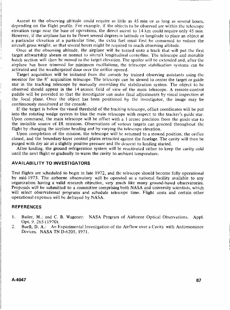
Ascent to the observing altitude could require as little as 45 min or as long as several hours, depending on the flight profile. For example, if the objects to be observed are within the telescope elevation range near the base of operations, the direct ascent to 14 km could require only 45 min. However, if the airplane has to be flown several degrees in latitude or longitude to place an object at a particular elevation at a particular time, the extra fuel must first be consumed to reduce the aircraft gross weight, so that several hours might be required to reach observing altitude.
Once at the observing altitude, the airplane will be turned onto a track that will put the first target athwartship abeam or normal to aircraft longitudinal centerline. The telescope and movable hatch section will then be moved to the target elevation. The spoiler will be extended and, after the airplane has been trimmed for minimum oscillations, the telescope stabilization systems can be activated and the weatherproof door over the orifice opened.
Target acquisition will be initiated from the console by trained observing assistants using the monitor for the 8" acquisition telescope. The telescope can be slewed to center the target or guide star in the tracking telescope by manually overriding the stabilization system. The object to be observed should appear in the 14 arcmin field of view of the main telescope. A remote-control paddle Wi!: lie piot.ibcd SO that the investigator can make f k a l adjustments by v i s ~ ~ 4 jncnprtinn .."Y -- ..-.. at the focal plane. Once the object has been positioned by the investigator, the image may be continuously monitored at the console.
If the target is below the visual threshold of the tracking telescope, offset coordinates will be put into the rotating wedge system to bias the main telescope with respect to the tracker's guide star. Upon command, the main telescope will be offset with a 1 arcsec precision from the guide star to the invisible source of IR missions. Observations of various targets can proceed throughout the flight by changing the airplane heading and by varying the telewope elevation.
Upon completion of the mission, the telescope will be returned to a stowed position, the orifice closed, and the boundary-layer control plates retracted against the fuselage. The cavity will then be purged with dry air at a slightly positive pressure and the descent to landing started.
After landing, the ground refrigeration system will be reactivated either t o keep the cavity cold until the next flight or gradually to warm the cavity t o ambient temperature.
AVAl LAB1 LITY TO INVESTIGATORS
Test flights are scheduled to begin in late 1972, and the telescope should become fully operational by mid-1973. The airborne observatory will be operated as a national facility available to any organization having a valid research objective, very much like many ground-based observatories. Proposals will be submitted to a committee comprising both NASA and university scientists, which will select observational programs and schedule telescope time. Flight costs and certain other operational expenses will be defrayed by NASA.
REFERENCES
1 . Bader, M.; and C. B. Wagoner: NASA Program of Airborne Optical Observations. Appl.
2. An Experimental Investigation of the Airflow over a Cavity with Antiresonance Opt. 9. 265 (1970). Buell, D. A.: Devices. NASA TN D-6205, 197 1 .
A-4047 87
DISCUSSION H. Seifert:
Author:
Why is the telescope elevation angle limited t o 75" F?
The 40" telescope elevation range (35" to 75" ) was determined primarily by aircraft structural considerations - the extent to which the fuselage structure could be cut away and air frame loads carried around the opening. The 75" elevation limitation does not pose a problem in that the object to be observed can always be brought within the telescope elevation range by flying to a higher or lower latitude or observing the object prior to or after its transit of the local meridian.
M. L . Boehme: What is the total weight of the telescope system supported or "floated" on the air bearing?
Author: The telescope system weight supported by the air bearing is 5 100 lb including 440 lb for the 16-in.-dia ball.
A-4047
THE GODDARD HELICAL TAPE RECORDER
Frank T. Martin and
Dennis K. McCarthy NASA Goddard Space Flight Center
Greenbelt, Maryland
ABSTRACT. A spacecraft recorder was developed with the objective of functioning continuously for 5 years. The resulting design employed a metallic tape wound in a 200-turn helix. A direct-drive, brushless DC torquer and servo speed control drove the recorder at 3 rpm for recording and 54 rpm for playback.
INTRODUCTION
All magnetic recording techniques require large surface areas for data storage since each data bit requires a discrete area and the data bits number in the millions. This requirement generally rules out drum recorders and disks, which are mechanically the least complex, for flight recording because of an unfavorable ratio of magnetic storage surface area to volume. Tape systems in which the data are stored on thin concentric layers solve the data storage problem, but most are complex devices.
The objective of this project was to develop a recorder with a long life expectancy (- 5 years) and still meet the specification requirements of reel-to-reel and endless loop, the two principal types of recorders used in spacecraft today. This included:
1. 2. 3. 4. 5 . 6.
A storage capacity of 6 X 1 O6 bits A bit density of 2,000 bits per inch Signal flutter of less than 3 percent (3a peak to peak, 0 to 625 Hz bandwidth) AM modulation of less than 20 percent Operation a t temperatures between-35" to +50° C Weight of less than 7 Ib
CONVENTIONAL SPACECRAFT RECORDERS
Most spacecrdt recorders are either of two types: reel-to-reel or endless loop. The reel-to-reel recorders (fig. 1 ) pass tape from a storage spool across the recording head and on to the takeup spool. A primary disadvantage of this type of recorder is its mechanical complexity. If the tape is to move across the head at a uniform velocity, the angular velocity of the storage reel must continually increase. Simultaneously, the velocity of the takeup reel must continually decrease. These adjustments are accomplished with a series of belts, pulleys, and clutches. Accurate control of the reel n:o tion is difficult since speeds, effective torque radii, and inertias are continually changing. Thus, a prime function of the tape transport system is to isolate the tape at the record head from disturbances inherent in the reeling mechanization.
bor playback the tape is reversed and its speed increased approximately 20 times by shifting clutches and drive belt assemblies. The high-speed playback is required because of the limited time a spacecraft may be above a given tracking station.
A-4047 89
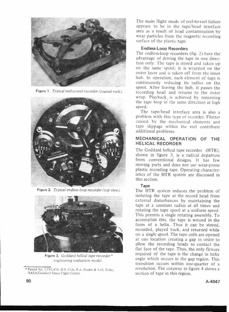
Figure 1. Tvpical reel-to-reel recorder (coaxial reels).
Figure 2. Spica1 endless loop recorder (top view).
Figure 3. Godtiard Iirlica! tape recorder- er:giineeririg evaluation model.
*Patent No. 3,592,478-P.T. Cole, P.A. Studer & A.O. Tyler, NASA/Goddard Space Flight Center
90
The main flight mode of reel-to-reel failure appears to be in the tape/head interface area as a result of head contamination by wear particles from the magnetic recording surface of the plastic tape.
Endless-Loop Recorders The endless-loop recorders (fig. 2) have the advantage of driving the tape in one direc- tion only. The tape is stored and taken up on the same spool; it is wrapped on the outer layer and is taken off from the inner hub. In operation, each element of tape is continuously reducing its radius on the spool. After leaving the hub, it passes the recording head and returns t o the outer wrap. Playback- is achieved by rerunning the tape loop in the same direction at high speed.
The tape/head interface area is also a problem with this type of recorder. Flutter caused by the mechanical elements and tape slippage within the reel contribute additional problems.
MECHANICAL OPERATION OF THE HELICAL RECORDER
The Goddard helical tape recorder (HTR), shown in figure 3, is a radical departure from conventional designs. I t has few moving parts and does not usc wear-prone plastic recording tape. Operating character- istics of the HTR system are discussed in this section.
The HTR system reduces the problem of isolating the tape at the record head from external disturbances by maintaining the tape at a constant radius at all times and rotating the tape spool at a uniform speed. This permits a single rotating assembly. To accomplish this, the tape is wound in the form of a helix. Thus it can be stored, recorded, played back, and returned while on a single spool. The tape coils are opened at one location creating a gap in order to allow the recording heads to contact the flat face of the tape. Thus, the only flexure required of the tape is the change in helix angle which occurs in the gap region. This transition occurs within one-quarter of a revolution. The cutaway in figure 4 shows a section of tape in this region.
Tape
A-4047
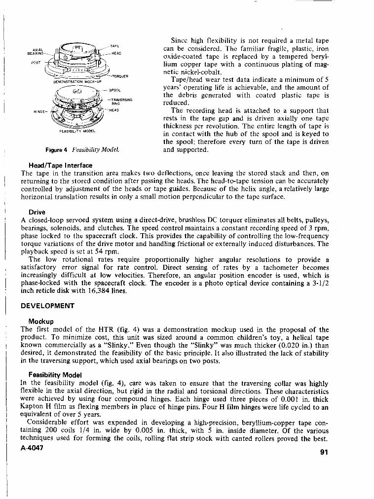
Since high flexibility is iiot required a iiietal tape can be considered. The familiar fragile, plastic, iron oxide-coated tape is replaced by a tempered beryl- lium copper tape with a continuous plating of mag- netic nickel-cobalt.
Tape/head wear test data indicate a minimum of 5 years’ operating life is achievable, and the amount of the debris generated with coated plastic tape is reduced.
The recording head is attached t o a support that rests in the tape gap and is driven axially one tape thickness per revolution. The entire length of tape is in contact with the hub of the spool and is keyed to FEASIBILITY MODEL
Figure 4 Feasibility Model. the spool; therefore every turn of the tape is driven and supported.
Head/Tape Interface The tape in the transition area makes two deflections, once leaving the stored stack and then, on returning to the stored condition after passing the heads. The head-to-tape tension can be accurately controlled by adjustment of the heads or tape guides. Because of the helix angle, a relatively large horizontal translation results in only a small motion perpendicular to the tape surface.
Drive A closed-loop servoed system using a direct-drive, brushless DC torquer eliminates all belts, pulleys, bearings, solenoids, and clutches. The speed control maintains a constant recording speed of 3 rpm, phase locked to t h t spacecraft clock. This provides the capability of controlling the low-frequency torque variations of the drive motor and handling frictional or externally induced disturbances. The playback speed is set at 54 rpm.
The low rotational rates require proportionally higher angular resolutions to provide a satisfactory error signal for rate control. Direct sensing of rates by a tachometer becomes increasingly difficult at low velocities. Therefore, an angular position encoder is used, which is phase-locked with the spacecraft clock. The encoder is a photo optical device containing a 3-1/2 inch reticle disk with 16,384 lines.
DEVELOPMENT
Mockup The first model of the HTR (fig. 4) was a demonstration mockup used in the proposal of the product. To minimize cost, this unit was sized around a common children’s toy, a helical tape known commercially as a “Slinky.” Even though the “Slinky” was much thicker (0.020 in.) than desired, it demonstrated the feasibility of the basic principle. It also illustrated the lack of stability in the traversing support, which used axial bearings on two posts.
In the feasibility model (fig. 4), care was taken to ensure that the traversing collar was highly flexible in the axial direction, but rigid in the radial and torsional directions. These characteristics were achieved by using four compound hinges. Each hinge used three pieces of 0.001 in. thick Kapton H film as flexing members in place of hinge pins. Four H film hinges were life cycled to an equivalent of over 5 years.
Considerable effort was expended in developing a high-precision, beryllium-copper tape con- taining 200 coils 1/4 in. wide by 0.005 in. thick, with 5 in. inside diameter. Of the various techniques used for forming the coils, rolling flat strip stock with canted rollers proved the best.
Feasibility Model
A-4047 91
However, squeezing the flat stock more one one side of the tape than the other caused a slight, but tolerable, taper across its face. Control of the diameter proved to be extremely sensitive to the smallest variations in stock thickness and rolling temperature. Fortunately many of the sins of fabrication were forgiven by annealing and tempering the coils on an axially preloaded mandrel.
The first successful recordings and playback of the HTR design were made with the feasibility model. However, two deficiencies were apparent: first, the traversing ring required additional torsional rigidity; and second, after extended use, angular and axial displacement of the tape relative to the spool closed the traversing gap.
The engineering evaluation model incorporated rugged pin hinges t o support the traversing ring. Displacement of the tape was eliminated by controlled assembly procedures and thz use of six keys between the spool and the tape. A new brushless DC torquer using armature-position photosensors was adapted to the speed control system.
Bench testing and vibration signature analysis indicated that isolation of the recording heads from the traversing ring motion would further reduce flutter. The final version of the engineering evaluation model incorporating a free floating recording head support is shown in fig. 3 . Thermal testing between -25" C and 4-50" C and vibration testing to the Delta vehicle flight levels were successful. An accelerated 1 year life test was also completed.
Flutter measurements of 4 to 6 percent peak to peak ( 3 0 ) have been measured. These measurements vary consistently along the tape, indicating a relationship with tape quality. Further iinprovemeni in the fabrication of helical tapes is required to bring them up to flight quality. Life tests are being continued in order to reveal any additional design weaknesses.
Engineering Evaluation Model
CONCLUSIONS
The engineering evaluation has demonstrated that the original goals are obtainable and that the HTR is ready for flight application. Additional improvements can be made in the design to further improve its performance and reliability.
92 A-4047
DISCUSSION R. W. Wilkes: How is the traversing ring powered?
Author: The traversing ring is “locked” into the tape helix by means of its guides (which create a gap). Thus for every turn of the spool, the ring moves one tape thickness (0.005 in.). It is driven much like a nut on a screw.
B. W. Firth: Why does the recording head need support other than from the traversing ring?
Author: On the feasibility model, the recording head was attached to the traversing ring where it experienced considerable ring motion perturbations. In addition, the resulting head and tape forces differed between the upward and downward directions.
These preb!err?s were c)vercone by attaching the recording head to an independent support assembly, which was guided and driven similar to the traversing ring. It traverses perpendicular to the exposed helical tape section, which is 7” from the spool axis.
R. W. Wilkes: Is the recording head support loaded to offset the 1 g effect so that guide-to-tape pressure is uniform between ground testing and space operations?
Author: No. The large mechanical advantage afforded by the shallow (0.005 in./revolution) helix makes the 1 g effect negligible so far as the drive is concerned. The head-to-tape pressure is set by the mechanical assembly of recording head and tape guides, which control the “wrap” independently of the “g” environment.
Bill Roth: How is the brushless dc direct drive motor commutated and controlled?
Author: A photodiode system has been used to sense armature position and control commutation. Recently, a hall-effect sensing system was developed.
Speed control of the recorder is achieved by a hybrid digital analog servo. Motor current is controlled based on a phase comparison between the signal from a precision photo-optical encoder, attached to the spool, and the spacecraft clock signal.
Lou Poluski: How is “print through” prevented?
Author: “Print through” (the transfer of magnetic information between the tape sections in contact with each other) is prevented because of the thickness (0.005 in.) and nonmagnetic properties of the beryllium copper tape.
, A-4047 93

SHUTTER MECHANISM FOR SPACECRAFT SPECTROPHOTOMETER
August Weilbach Beckman Instruments, Inc.
Fullerton, California
ABSTRACT. This paper describes a shutter mechanism for the backscatter ultraviolet spectrophotometer (BUV) experiment on the Nimbus D Satellite. The purpose of the experiment is to determine spatial distribution of atmospheric ozone from measure- ments of ultraviolet radiation backscattered by the earth's atmosphere.
The system consists of two independent, rotary-cylinder shutters, controlled by a dual-star Geneva mechanism, and driven by a single stepper motor. A single driver controls a combination of two independently driven Geneva stars. Important design considerations involved the use of low-friction, nonmetallic materials.
INTRODUCTION
The Backscatter Ultraviolet Spectrophotometer (BUV) is one of several instruments launched aboard the Nimbus D weather satellite on April 8, 1970. The satellite was placed in orbit around the earth at an altitude of approximately 650 mi. As of May lY71, the BUV is still performing within specifications.
The purpose of the BUV instrument is to determine ozone distribution-during both sunlight and moonlight excitation-by measuring ultraviolet energy backscattered by the earth's atmos- phere. This information provides scientists with a spectral view of the earth's atmosphere and is important for long-range weather forecasting.
COLLIMATtNG MIRRORS INTERMEDIATE SLI
45 -90" PRISM PHOTOMETRIC SOURCE-
MlRR
SLIT ASS
ARlM GRATING
GEARHEAD AN0 RETAINERS SOURCE -MONOCHAOMATOR
Figure 1 BUV Instrument cutaway showing interior details.
Basically, the instrument consists of a mono- chromator, a photometer, ultraviolet (UV) detect- ors (photomultipliers), calibration sources, optics, and electronics (fig. 1). The complete instrument is enclosed in a limited-access, highdensity package measuring 6 X 8 X 22 in.
An early evaluation of various shutter systems for the monochromator-such as butterfly disks, slide shutters, cam actuators, and linkages,- indicated a need for a new approach to cope with the operational requirements and the space limita- tions for this instrument. Depending on the operating mode of the spectrophotometer, the shutters had to operate independently or together. Internal photometric and wavelength calibration had to be performed periodically. Zero light leakage was reauired during the dark current - -
mode. One-year lifetime and reliability were required. Four units were built, all with identical shutter systems. The problem encountered during testing of the engineering model was excessive thickening of the lubricant within the motor gear-head bearings under the low-temperature test. This condition in turn stalled the low-torque motor. This paper discusses the solution to this problem and other considerations in the shutter design.
A-4047 95
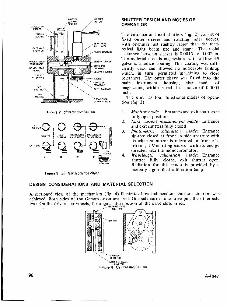
PINION WUPLING
GENEVA DRIVER DRIVEN STAR
GENEVA HOUSING
UTER SLEEVE
Figure 2 Shutter mechanism.
I l l I21 I31
VIEW A-A
SHUTTER DESIGN AND MODES OF OPERATION
The entrance and exit shutters (fig. 2) consist of fixed outer sleeves and rotating inner sleeves, with openings just slightly larger than the theo- retical light beam size and shape. The radial clearance between sleeves is 0.0015 to 0.002 in. The material used is magnesium, with a Dow #9 galvanic anodize coating. This coating was suffi- ciently dark and showed no noticeable buildup which, in turn, permitted machining to close tolerances. The outer sleeve was fitted into the main instrument housing, also made of magnesium, within a radial clearance of 0.0005 inch.
The unit has four functional modes of opera- tion (fig. 3):
1. Monitor mode: Entrance and exit shutters in fully open position.
2. Dark current measurement mode: Entrance and exit shutters fully closed.
3. Photometric calibration mode: Entrance shutter closed at front. A side aperture with its adjacent mirror is relocated in front of a tritium, UV-emitting source, with its energv directed into the monochromator.
4. Wavelength calibration mode: Entrance shutter fully closed, exit shutter open. Radiation for this mode is provided by a mercury-argon-filled calibration lamp.
Figure 3 Shutter sequence chart.
DESIGN CONSIDERATIONS AND MATERIAL SELECTION
A sectioned view of the mechanism (fig. 4) illustrates how independent shutter actuation was achieved. Both sides of the Geneva driver are used. One side carries one drive pin, the other side two. On the driven star wheels, the angular distribution of the drive slots varies.
STAR-ENTRANCE SHUTTER
Figure 4 Geneva mechanism.
96 A-4047
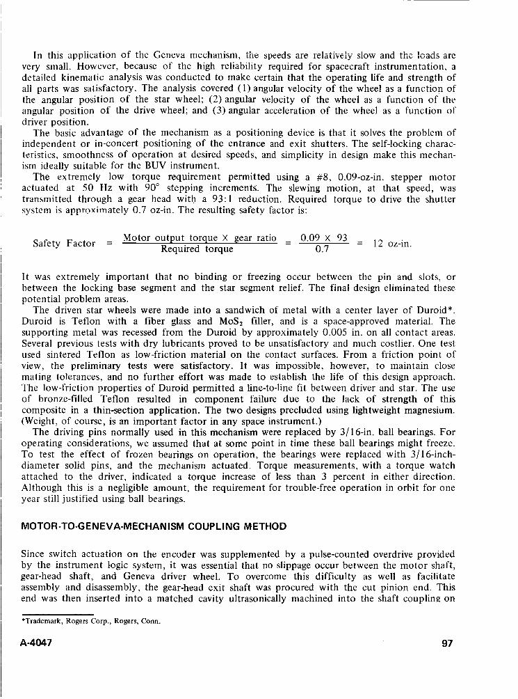
in this application of the Geneva mechanism, tiie speeds are relatively slow aiid the loads arc very small. However, because of the high reliability required for spacecraft instrumentation, a detailed kinematic analysis was conducted to make certain that the operating life and strength of all parts was satisfactory. The analysis covered (1) angular velocity of the wheel as a function of the angular position of the star wheel; (2)angular velocity of the wheel as a function of the angular position of the drive wheel; and (3) angular acceleration of the wheel as a function of driver position.
The basic advantage of the mechanism as a positioning device is that it solves the problem of independent or in-concert positioning of the entrance and exit shutters. The self-locking charac- teristics, smoothness of operation at desired speeds, and simplicity in design make this mechan- ism ideally suitable for the BUV instrument.
The extremely low torque requirement permitted using a #8, 0.09-oz-in. stepper motor actuated at 50 Hz with 90" stepping increments. The slewing motion, at that speed, was transmitted through a gear head with a 93:l reduction. Required torque to drive the shutter system is approximately 0.7 oz-in. The resulting safety factor is:
= 12 oz-in. Motor output torque X gear ratio - - 0.09 X 93 0.7 Safety Factor = Required torque
It was extremely important that no binding or freezing occur between the pin and slots, or between the locking base segment and the star segment relief. The final design eliminated these potential problem areas.
The driven star wheels were made into a sandwich of metal with a center layer of Duroid*. Duroid is Teflon with a fiber glass and MoS, filler, and is a space-approved material. The supporting metal was recessed from the Duroid by approximately 0.005 in. on all contact areas. Several previous tests with dry lubricants proved to be unsatisfactory and much costlier. One test used sintered Teflon as low-friction material on the contact surfaces. From a friction point of view, the preliminary tests were satisfactory. It was impossible, however, to maintain close mating tolerances, and no further effort was made to establish the life of this design approach. The low-friction properties of Duroid permitted a line-to-line fit between driver and star. The use of bronze-filled Teflon resulted in component failure due to the lack of strength of this composite in a thin-section application. The two designs precluded using lightweight magnesium. (Weight, of course, is an important factor in any space instrument.)
The driving pins normally used in this mechanism were replaced by 3/16-in. ball bearings. For operating considerations, we assumed that at some point in time these ball bearings might freeze. To test the effect of frozen bearings on operation, the bearings were replaced with 3/16-inch- diameter solid pins, and the mechanism actuated. Torque measurements, with a torque watch attached to the driver, indicated a torque increase of less than 3 percent in either direction. Although this is a negligible amount, the requirement for trouble-free operation in orbit for one year still justified using ball bearings.
MOTOR-TO-G EN EVA-M ECHAN ISM COUPLING METHOD
Since switch actuation on the encoder was supplemented by a pulse-counted overdrive provided by the instrument logic system, it was essential that no slippage occur between the motor shaft, gear-head shaft, and Geneva driver wheel. To overcome this difficulty as well as facilitate assembly and disassembly, the gear-head exit shaft was procured with the cut pinion end. This end was then inserted into a matched cavity ultrasonically machined into the shaft coupling on
*Trademark, Rogers Corp., Rogers, Conn
A-4047 97
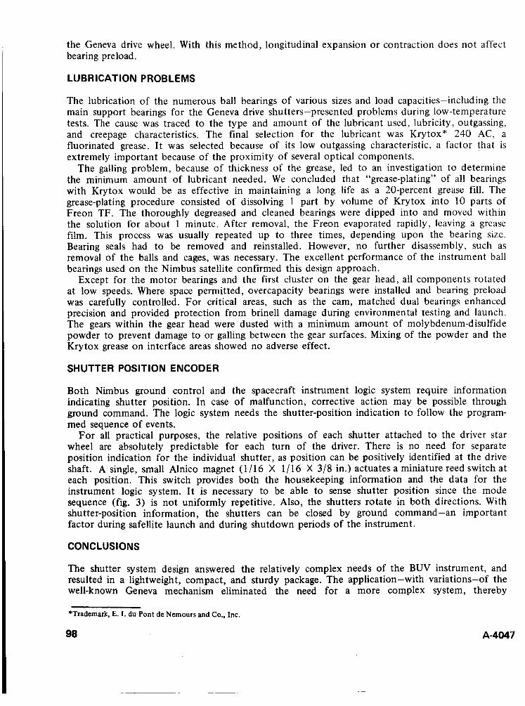
the Geneva drive wheel. With this method, longitudinal expansion or contraction does not affect bearing preload.
LUBRICATION PROBLEMS
The lubrication of the numerous ball bearings of various sizes and load capacities-including the main support bearings for the Geneva drive shutters-presented problems during low-temperature tests. The cause was traced to the type and amount of the lubricant used, lubricity, outgassing, and creepage characteristics. The final selection for the lubricant was Krytox” 240 AC, a fluorinated grease. I t was selected because of its low outgassing characteristic, a factor that is extremely important because of the proximity of several optical components.
The galling problem, because of thickness of the grease, led to an investigation to determine the minimum amount of lubricant needed. We concluded that “grease-plating” of all bearings with Krytox would be as effective in maintaining a long life as a 20-percent grease fill. The grease-plating procedure consisted of dissolving 1 part by volume of Krytox into 10 parts of Freon TF. The thoroughly degreased and cleaned bearings were dipped into and moved within the solution for about 1 minute. After removal, the Freon evaporated rapidly, leaving a grease film. This process was usually repeated up to three times, depending upon the bearing size. Bearing seals had to be removed and reinstalled. However, no further disassembly, such as removal of the balls and cages, was necessary. The excellent performance of the instrument ball bearings used on the Nimbus satellite confirmed this design approach.
Except for the motor bearings and the first cluster on the gear head, all components rotated at low speeds. Where space permitted, overcapacity bearings were installed and bearing preload was carefully controlled. For critical areas, such as the cam, matched dual bearings enhanced precision and provided protection from brine11 damage during environmental testing and launch. The gears within the gear head were dusted with a minimum amount of molybdenum-disulfide powder to prevent damage to or galling between the gear surfaces. Mixing of the powder and the Krytox grease on interface areas showed no adverse effect.
SHUTTER POSITION ENCODER
Both Nimbus ground control and the spacecraft instrument logic system require information indicating shutter position. In case of malfunction, corrective action may be possible through ground command. The logic system needs the shutter-position indication to follow the program- med sequence of events.
For all practical purposes, the relative positions of each shutter attached to the driver star wheel are absolutely predictable for each turn of the driver. There is no need for separate position indication for the individual shutter, as position can be positively identified at the drive shaft. A single, small Alnico magnet (1 / 16 X 1 / 16 X 3/8 in.) actuates a miniature reed switch at each position. This switch provides both the housekeeping information and the data for the instrument logic system. I t is necessary to be able to sense shutter position since the mode sequence (fig. 3) is not uniformly repetitive. Also, the shutters rotate in both directions. With shutter-position information, the shutters can be closed by ground command-an important factor during safellite launch and during shutdown periods of the instrument.
CONCLUSIONS
The shutter system design answered the relatively complex needs of the BUV instrument, and resulted in a lightweight, compact, and sturdy package. The application-with variations-of the well-known Geneva mechanism eliminated the need for a more complex system, thereby
*Trademark, E. 1. du Pont de Nemours and Co., Inc.
98 A-4047

providing a higher degree of reliability. The Geneva mechanism is ideal for slow and medium speed applications where accurate 2nd locked positioning at the output are requirements. A cylindrical rotary shutter with a dark surface finish provided an excellent light seal when closed. It also permitted proper masking of the entrance and exit beam, thus eliminating stray light. Using magnesium wherever possible not only kept the weight low, but also allowed clean, close-tolerance machining and application of a dark and protective finish without buildup.
Grease plating of ball bearings-although limited t o low loads and speeds-does provide reliable and long-term protection against galling, cold weldings, and outgassing.
~ A-4047 99
DISCUSSION H. Smaller: You mentioned that an anodized surface could not be used. Could you go into detail on why this was so?
Author: My comment that at the time of construction of the BUV instrument an anodized finish was not acceptable within finishing specifications was only partially correct. Let me qualify the statement.
An ordinary black anodize finish on aluminum would not have been acceptable for two reasons: ( 1 ) possible outgassing from the black dye could contaminate the surfaces of the numerous optical components such as gratings, collimating mirrors, and lenses; and (2) surfaces of the instrument exposed to outer space radiation and intense sunlight could bleach to an extent as to reflect and scatter unwanted light into the optical system and thus increase stray light problems.
Notice that I stated in the paper the material used for the instrument was magnesium and the dark finish was DOW No. 9 galvanic anodize treated surface without noticeable buildup, which in turn permitted machining of the components (shutter and others) t o final tolerances. Had we used aluminum we would have needed t o make allowance for the anodize finish. This would have been inconvenient in areas where 6.002 in. tolerances were important in fitting ball bearings and bearing supports.
Lloyd Selene: At what temperatures for operational performance was the unit qualified? At what temperature did the bearing grease “freeze?”
Author: The operational performance temperature was 28” C. The test performance temperature was specified at -25” C to 55” C (thermal vacuum test).
Excessive thickening of the Krytox grease occurred at +2” C, which in turn resulted in “freezing” of the various bearings.
Consideration for this test was possible failure of the Nimbus spacecraft temperature control system and thus exposure of the various experiments t o above or below the specified performance temperature.
Had the available drive motors torque been sufficient, the thickening would probably have been of no great significance since no damaging contamination of optical surfaces was observed during three 48-hr runs in the thermal vacuum test.
100 A-4047
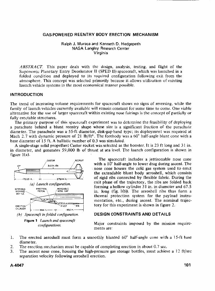
GAS-POWERED REENTRY BODY ERECTION MECHANISM
Ralph J. Muraca and Kenneth D. Hedgepeth NASA Langley Research Center
Virginia
ABSTRACT. This paper deals with the design, analysis, testing, and flight of the Supersonic Planetary Entry Decelerator I1 (SPED 11) spacecraft, which was launched in a folded condition and deployed to its required configuration following exit from the atmosphere. This concept was selected primarily because it .allows utilization of existing launch vehicle systems in the most economical manner possible.
INTRODUCTION
The trend of increasing volume requirements for spacecraft shows no signs of reversing, while the family of launch vehicles currently available will remain constant for some time to come. One viable alternative for the use of larger spacecraft within existing nose fairings is the concept of partially or fully erectable structures.
1 he primary purpose of this syauxraft expeihe i i t w;ls to dctcimine t he fezsibi!ity ef dep!oying a parachute behind a blunt reentry shape whose size is a significant fraction of the parachute diameter. The parachute was a 55-ft diameter, disk-gap-band type; its deployment was required at Mach 2.7 with dynamic pressure of 21 lb/ft2. The forebody was a 60" half-angle blunt cone with a base diameter of 15 ft. A ballistic number of 0.3 was simulated.
A single-stage solid propellant Castor rocket was selected as the booster. I t is 23 ft long and 3 1 in. in diameter, and generates 59,000 lb of thrust at sea level. The launch configuration is shown in figure l(a).
The spacecraft includes a jettisonable nose cone with a 10" half-angle to lower drag during ascent. The nose cone houses the cold gas system used t o erect the extendable blunt body aeroshell, which consists of rigid ribs connected by flexible fabric. During the exit phase of the trajectory, the ribs are folded back forming a hollow cylinder 3 1 in. in diameter and 67.5
STORAGE in. long (fig. l(b)). The aeroshell ribs thus form a thermal protection system for the payload instru- mentation, etc., during ascent. The nominal trajec- tory for this experiment is shown in figure 2.
DESIGN CONSTRAINTS AND DETAILS
Major constraints imposed by the mission require- ments are:
__
RECRUIT
+
,- ~ p17263,n-27944,np~
(a) Launch configuration. NITROGEN
BOTTLE
ERECTION
( b ) Spacecraft in folded configuration.
CY LlNDER
Figure 1 Launch and spacecraft configurations.
1.
2. 3.
The erected aeroshell must form a smoothly blunted 60" half-angle cone with a 15-ft base diameter. The erection mechanism must be capable of completing erection in about 0.7 sec. The ascent nose cone, housing the high-pressure gas storage bottles, must achieve a 12 ft/sec separation velocity following aeroshell erection.
A-4047 101
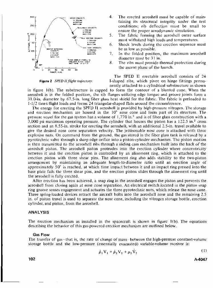
/
h @- -*FULL ERECTION 1184WOfll I ,240.6 YC
MAC". 288 q.4.ssplf \
\-TEST POINT Il+WfWfll I ,256.8 Y C
MACH .2.70 4.21.0 PSf
*HlNGE YOYEHT =7498!n.-lb BIAWLITED IN F U L L - X I L E WIND TUNNEL AT q.ll.S
0 IO 20 30 40 50 60 RANGE, n.ml.
Figure 2 SPED IIflight trajectoiy
4. The erected aeroshell must be capable of main- taining its structural integrity under the test conditions; rib deflection must be small to ensure the proper aerodynamic simulation. The fabric forming the aeroshell outer surface must withstand high loads and temperatures. Shock levels during the erection sequence must be as low as possible. In the folded position, the maximum aeroshell diameter must be 3 1 in. The ribs must provide thermal protection during the ascent phase of the launch.
5.
6.
7.
8.
The SPED I1 erectable aeroshell consists of 24 I-shaped ribs, which pivot on hinge fittings perma- nently attached to a cylindrical substructure as shown
in figure l(b). The substructure is capped to form the contour of a blunted cone. When the aeroshell is in the folded position, the rib flanges utilizing edge tongue and groove joints form a 31.0-in. diameter by 67.5-in. long fiber glass heat shield for the fabric. The fabric is preloaded to 1- 1 /2 times flight loads and forms 24 triangular-shaped flats around the circumference.
The energy for erecting. the SPED I1 aeroshell is provided by high-pressure nitrogen. The storage and erection mechanism are housed in the 10" nose cone and form part of its structure. The pressure vessel for the gas system has a volume of 1,770 in.3 and is of fiber glass construction with a 3,000 psi maximum operating pressure. The cylinder that houses the piston has a 122.5 in.2 cross section and an 8.55-in. stroke for erecting the aeroshell, with an additional 2.5-in. travel available to give the desired nose cone separation velocity. The jettisonable nose cone is attached with three explosive nuts. On command from the ground, the gas stored in the fiber glass tank is released by a pyrotechnic valve through a sharp edge orifice into a piston-cylinder mechanism. The piston motion is then transmitted to the aeroshell ribs through a sliding cam mechanism built into the back of the aeroshell piston. The aeroshell piston protrudes into the erection cylinder where concentricity between it and the erection piston is controlled by an alinement ring, which is attached to the erection piston with three shear pins. The alinement ring also adds stability to the two-piston arrangement by maintaining an adequate length-to-diameter ratio until an erection angle of approximately 50" is reached, at which time impact between it and an impact ring pressed into the base plate fails the three shear pins, and the erection piston slides through the alinement ring until the aeroshell is fully erected.
After erection has been achieved, a snap ring in the aeroshell engages the piston and prevents the aeroshell from closing again at nose cone separation. An electrical switch located in the piston snap ring groove senses engagement and actuates the three pyrotechnic nuts, which release the nose cone. Three spring-loaded devices retract the aircraft bolts into the aeroshell nose and the remaining 2.5 in. of piston travel is used to separate the nose cone, including the nitrogen storage bottle, erection cylinder, and piston, from the aeroshell.
ANALYSIS
The erection mechanism as installed in the spacecraft is shown in figure l(b). The equations describing the behavior of this gas-powered erection mechanism are outlined below.
Gas Flow The transfer of gas-that is, the rate of change of mass-between the high-pressure constant-volume storage bottle and the low-pressure (essentially evacuated) variable-volume receiver is:
102
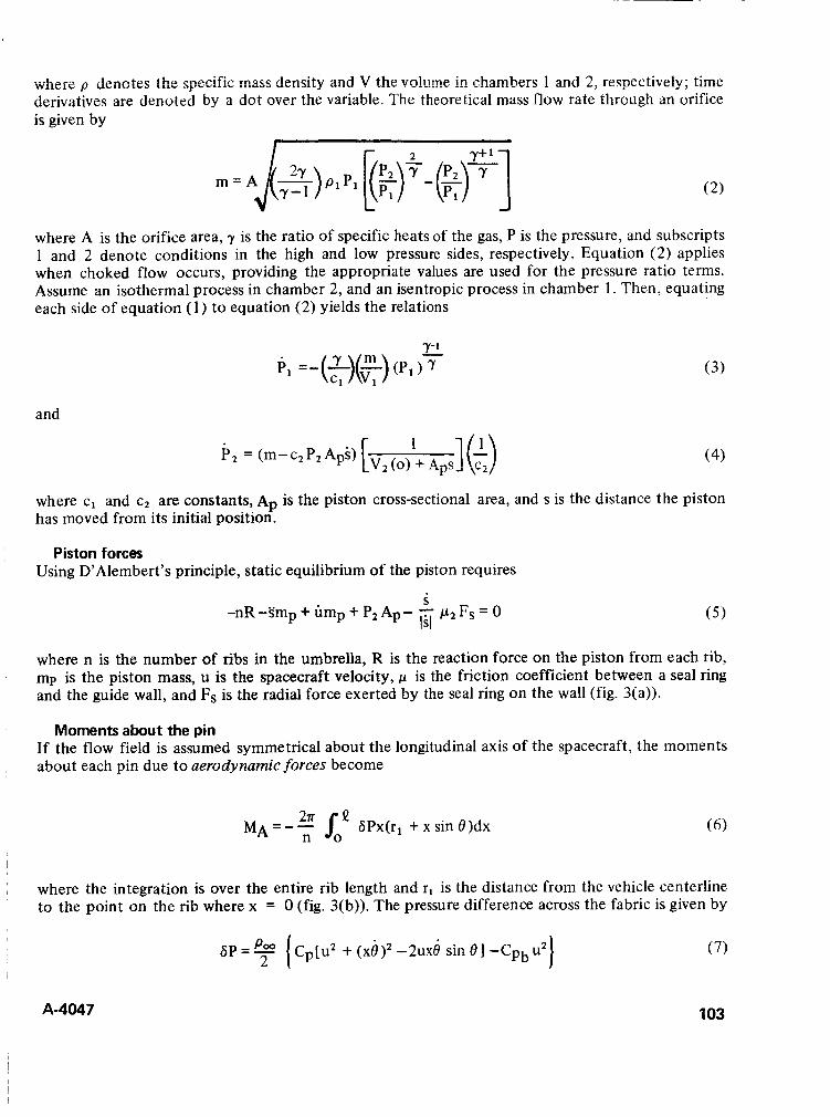
where p denotes the specific mass density 2nd V the vo!ume in chambers 1 and 2j respectively; time derivatives are denoted by a dot over the variable. The theoretical mass flow rate through an orifice is given by
where A is the orifice area, y is the ratio of specific heats of the gas, P is the pressure, and subscripts 1 and 2 denote conditions in the high and low pressure sides, respectively. Equation (2) applies when choked flow occurs, providing the appropriate values are used for the pressure ratio terms. Assume an isothermal process in chamber 2, and an isentropic process in chamber 1. Then, equating each side of equation (1) to equation (2) yields the relations
Y- 1
and
where c, and c2 are constants, Ap is the piston cross-sectional area, and s is the distance the piston has moved from its initial position.
Piston forces Using D’Alembert’s principle, static equilibrium of the piston requires
s -nR-smp+ump+P A p- - p z F s = O IS1 (5)
where n is the number of ribs in the umbrella, R is the reaction force on the piston from each rib, mp is the piston mass, u is the spacecraft velocity, I-( is the friction coefficient between a seal ring and the guide wall, and Fs is the radial force exerted by the seal ring on the wall (fig. 3(a)).
Moments about the pin If the flow field is assumed symmetrical about the longitudinal axis of the spacecraft, the moments about each pin due to aerodynamic forces become
MA =- GPx(r, + x sin 8)dx n
~ where the integration is over the entire rib length and rl is the distance from the vehicle centerline to the point on the rib where x = 0 (fig. 3(b)). The pressure difference across the fabric is given by
’ A-4047 103
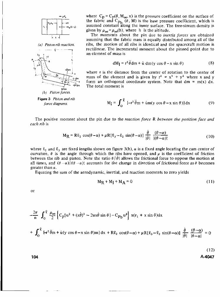
-mpCs-u)
cs-! (a) Piston-rib reaction.
6 - - 7 I
__ __
L. Y I
I 'I
where Cp = Cp(8, M,, x) is the pressure coefficient on the surface of the fabric and Cpb ( e , M) is the base pressure coefficient, which is assumed constant along the inner surface. The free-stream density is given by p,=p,(h), where h is the altitude.
The moments about the pin due to inertia forces are obtained assuming that the fabric mass is equally distributed among all of the ribs, the motion of all ribs is identical and the spacecraft motion is rectilinear. The incremental moment about the pinned point due to an element of mass is
dMI = r2$dm + U dm(y cos 8 -x sin 8) (8)
where r is the distance from the center of rotation to the center of mass of the element and is given by r2 = x2 + y2 where x and y form an orthogonal coordinate system. Note that dm = m(x) dx. The total moment is
Q MI = I [-r2$m + Gm(y cos 8-x sin e ) ] dx
0 (9)
( b ) Piston forces.
Figure 3 Piston and rib force diagrams.
The positive moment about the pin due to the reaction force R between the pos i t ion face and each rib is
e (8-a) lei i(e-a)i MR = RQ2 cos(8 -a) + pR[Q3 - Q 2 sin(8-a)] -
where II, and (I, are fixed lengths shown on figure 3(b), a is a fixed angle locating the cam center of curvature, 0 is the angle through which the ribs have opened, and p is the coefficient of friction between the rib and piston. Note the ratio e/l6l allows the frictional force to oppose the motion at all times, and (0 -a)/l(0 -a)( accounts for the change in direction of frictional force as 0 becomes greater than a.
Equating the sum of the aerodynamic, inertial, and reaction moments to zero yields
M R + MI + M A = O
or
Q e (8-a) = + 4 [-r28m + U(y COS 8-x sin 0)ml dx + RQ2 cos(8-a) + pR[Q3-Q2 sin@-a)] - - rei re-ai
104

The equation of motion for the piston can now be used in conjunction with the moment zqu2tion to e!iminate R. In addition, a constraint equation exists between s and 6, :
which can be used t o eliminate s from the system equations.
Spacecraft equation of motion If the yawing and pitching motions are ignored, the equation of motion in a direction tangent to the flight path of the spacecraft is given by
where Fn is the drag force on the spacecraft, m, is the total spacecraft mass, p is the angle between the flighr path and the local horizontal, u is the spacecraft velocity, mp is the piston mass, s is the piston acceleration with respect to the spacecraft, n is the number of ribs, m R is the rib mass, x,y locate the rib center of mass with respect to the pivot point on the spacecraft, and g is the gravitational acceleration. Note that the drag force can be written
Assuming CPb is constant over the entire base and assuming circumferential symmetry yields
where r is the local radius and rb is the base radius. The dynamic pressure q = p,u2 /?.
Trajectory equation Since the erection time is approximately 1 sec, a simplified equation can be used to account for altitude changes. Assuming rectilinear motion of the spacecraft,
The spacecraft erection dynamics can thus be defined, within the limitations and assumptions previously stated, by a system of five first- or second-order differential ecl uations with independent variable time and dependent variables PI , P, , 0 , u, and h, and a constraint equation relating s to 0 . The second-order equation in e is reduced to two first-order equations, thus giving six first-order differential equations. These are solved numerically using a Runge-Kutta method. In addition to predicting erection times for various sets of parameter values, the rib dynamic loads are computed along with the pin reactions and the reaction force R between t he piston and the rib cam. The purpose of this analysis is to provide a roo1 to aid the designers in the selection of orifice sizes and to determine dynamic and static loads on the aeroshell structure for a wide variety of conditions, > l i i i test and flight.
A-404-7 105

FABRICATION
Fabric installation The fabric was tested to determine its properties in the fill and warp direction, and bonding agents were selected to allow full fabric strength to be developed. The fabric was preloaded to 1-1 /2 time the maximum load t o set the fibers, and then installed on a frame at a preload of 1-1/2 time the nominal load. The frame was placed over the ribs and the fabric bonded to the ribs in the full open position. The trailing end of the fabric was reinforced with two additional layers to decrease flutter.
Rib flanges The flanges are made of fiber glass, which requires special cutters. The tongue and groove edges presented a machining problem because of close tolerances. All bolted joints required three-axis tape controlled machines because of the stringent alinement requirements.
TEST PROGRAM
A prototype spacecraft was developed to test the erectable aeroshell concept under simulated flight conditions.
The first test was conducted in the Langley Research Center (LRC) full-scale wind tunnel. The primary object was to determine the erection dynamics of the erectable aeroshell under a symmetrical and an asymmetrical aerodynamic loading. Although the flow was subsonic, the hinge moment expected for flight was simulated.
The effect of vacuum conditions on the erection dynamics of the aeroshell was studied in several tests conducted in the 60-ft vacuum sphere at Langley. The spacecraft was suspended from the rear by elastic cords to simulate free-body effects. The final test conducted was a complete sequence-of-even t test .
These two test series uncovered problems in the rib restraint cable, and some instruments had to be relocated because of erection shocks.
A full-scale spacecraft was used to test the erection mechanism. These tests provided confidence in the erection system and structural integrity of the spacecraft. They also provided a means of assessing the accuracy of the analysis. The parameter of prime concern is erection time. Table 1 compares computed and measured values of erection time for various ambient conditions and storage bottle pressures. The erection angle tJ from test and analysis is shown in figure 4(a). Rib loads also were measured in the full-scale tunnel tests; measured and calculated rib loads at the hinge point are compared in figure 4(b).
VACUUM SPIfRE TEST h = l 8 5 W f t Table 1 Comparison of Computed and Measured Erection Times
s::[ 7 , , , --2o sec
(a) Erection angle vs. time.
Erection time,
0 . I .2 .3 .4 .5 .6 .7 .8 .9 Nitrogen pressure, Condition Measured Computed TIME, Sec
Psig
WINO TUNNEL TEST q~11.91b/ft2 1080 Vacuum sphere 0.622 0.618
1080 Vacuum sphere 0.75 0.745 h = 185,000.0 = 0
h = 185,000,0 = 90"
q = 11 .9 ,0=0 0 .2 .4 .6 .8 1.0 1.2 1.4 16 1.8 1800 Wind tunnel 1.88 1.83
TIME, SeC
(b ) Hinge moment vs. time.
Figure 4 Comparison of measured computed data.
106 A-4047

CONCLUSIONS
The feasibility of using an erectable structure has been proven with the succcss of the SPED I1 spacecraft. The concepts used in the SPED I1 design have considerable potential for use in atmospheric entry systems on interplanetary probes. Although an exact analytical model accounting for all of the phenomena that affect the erection motions was not attempted, the model used in this analysis was shown to be adequate for engineering applications. The actual flight erection point was between the nominal and 30 low conditions, and the actual erection time was bracketed by the calculated times for these conditions.
A-4047 107

THE INTELSAT IV ANTENNA POSlTlONER
Frank A. Glassow Hughes Aircraft Company
El Segundo, California
ABSTRACT. The Intelsat IV communications satellite has two spot beam antennas which are pointed to selected land masses by gimbaled positioners. The positioners employ drive motors with electromagnetic brakes and jackscrews that are selfcaging during the launch environment. The positioner embodies successful use of dry lubricants on ball bearings, spur gears, screw and nut, and various journal bearings. A coefficient of friction of ayproxima:e!y 0.05 was demor?strated in vacuum operation. Success of the positioner has been demonstrated on the first Intelsat IV placed in orbit in January 197 1. The developmental problems that were encountered and their solutions are discussed.
INTRODUCTION
The Intelsat IV communications satellite, first launched in January 197 1 , carries two high-gain, spot
positioner, which permits each antenna to be set and locked t o a selected pointing angie with respect to spacecraft coordinates prior to launch. Thus, to accomplish the initial mission of the satellite the positioners need not be operated. Since the satellite is intended to serve the communications requirements of 79 nations throughout the world, the need may arise to change the pointing angles of the antennas to serve different land masses on the earth after the satellite is in orbit. The positioner satisfies this need by responding to digital commands from the earth to change the pointing angle of the antenna to any region of the earth as viewed from its location in a synchronous orbit.
The antenna positioner for accomplishing the Intelsat IV requirement is reliable and lightweight, and it positively holds its pointing angle through launch environment without the aid of auxiliary locks. I t consumes no power in the holding mode and provides an accurate electrical signal of its position whether at rest or in motion.
I-.",, uGalll antennas. The parabolic reflector of each antenna is mounted on a two-axis gimbaled
R EQU I REMENTS
The antenna positioner is matched specifically to the requirements of synchronous communications satellites. In the Intelsat IV application the positioners are operated only in an open-loop mode in response to commands from the earth to move either axis through a specified angle.
Load The high-gain antenna feed assemblies are rigidly mounted on the despun platform of the satellite, an arrangement requiring that only the 50-in. parabolic reflector be carried and pointed by the antenna positioner. The 3.75-1b reflector is equipped with an integral mounting ring on the back side that bolts directly t o the three arms of the outer gimbal member of the positioner.
Angular Excursion Range Because of the fixed antenna feed arrangement and the position of the satellite in synchronous orbit, an angular motion of k4.45" for both the azimuth and elevation gimbals is sufficient t o point
A-4047 109
the antenna beam t8.2" . These angles are compatible with the spot beam width of 4.5" and the subtended angle of the Earth of 17.5" viewed from a synchronous orbit location.
Accuracv The positioner is required to hold its pointed angle to an accuracy of f0.05" and t o be capable of 0.05" incremental changes of pointing angle. The position transducer should have an elemental accuracy of 2 0.02".
Life The Intelsat IV satellite is required t o be operational for a period of 7 years; design criteria were established to provide a 10-year life to ensure margin. Because the positioner is expected t o be used only rarely in orbit, a total gimbal travel per axis of 100" was established as a maximum life requirement.
Position Indication The positioner is required t o incorporate a position transducer for each axis of motion which independently provides position information to the specified accuracy.
Holding Capability The positioners must be capable of holding pointing angles established during alignment operations on the earth without the aid of launch locks or deployment operations in orbit. The operational plan for the satellite is to interrogate the position angles to verify that pointing angles are correct after orbit has been achieved and to move the gimbal axes only if a change in mission plan requires a new pointing direction. This plan was carried out successfully on the satellite launched in January 197 1 , and it has been unnecessary to operate the positioner motors in orbit to this date.
Rate of Travel A change in pointing direction of a spot beam antenna would most likely be accompanied by a change in orbital location, which could require days or weeks to accomplish. Consequently, a period of several days to accomplish total travel of a given axis is acceptable.
Environment The Intelsat IV is launched with an 4tlas-Centaur boost vehicle. The positioner is qualified by vibrating to l o g at the mounting interface, causing 35 g of acceleration at the outer gimbal member. The vibration requirements are further defined as:
1. Sinusoidal: 5 t o 200 Hz; maximum acceleration, 15 to 60 Hz. 2. Random: 20 t o 2000 Hz; maximum rms acceleration, 50 to 1 10 Hz.
The positioner is required to hold the antenna reflector without changing its pointing angle by more than 0.05" at these accelerations.
The nonoperating temperature range has been established as -150" F to +250" F. Since operating periods may be selected and eclipse periods can be avoided, the operating temperature range was specified to be -1 00" F to +250" F.
torr a t synchronous altitude.
The normal pressure environment is the hard vacuum of space or approximately lo-'
Weight and Power Both weight and power must be held t o a minimum, or be nothing at all. Actually, the positioner consumes no power during the holding mode, and since that is all it does during most of the 7-year life span, the average power consumption should be virtually nil. If n o positioning capabilities were
110 A-4047
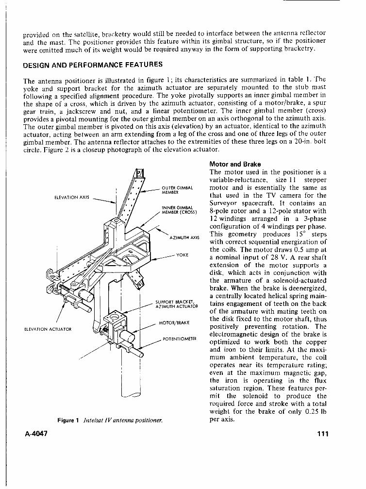
i;iovided c n the sate!lite, bracketry would still be needed to interface between the antenna reflector and the mast. The positioner provides this feature within its gimbal structure, so if the positioner were omitted much of its weight would be required anyway in the form of supporting bracketry.
DESIGN AND PERFORMANCE FEATURES
The antenna positioner is illustrated in figure 1; its characteristics are summarized in table 1. The yoke and support bracket for the azimuth actuator are separately mounted to the stub mast following a specified alignment procedure. The yoke pivotally supports an inner gimbal member in the shape of a cross, which is driven by the azimuth actuator, consisting of a motor/brake, a spur gear train, a jackscrew and nut, and a linear potentiometer. The inner gimbal member (cross) provides a pivotal mounting for the outer gimbal member on an axis orthogonal to the azimuth axis. The outer gimbal member is pivoted on this axis (elevation) by an actuator, identical to the azimuth actuator, acting between an arm extending from a leg of the cross and one of three legs of the outer gimbal member. The antenna reflector attaches to the extremities of these three legs on a 20-in. bolt circle. Figure 2 is a closeup photograph of the eievation actuator.
OUTER GIMBAL
ELEVATION AXIS
INNER GIMBAL MEMBER (CROSS)
AZIMUTH AXIS
SUPPORT BRACKET, AZIMUTH ACTUATOR
ELEVATION ACTUATOR
POTENTIOMETER
i.J Figure 1 intelsat ZV antenna positioner.
A-4047
Motor and Brake The motor used in the positioner is a variable-reluctance, size 1 1 stepper motor and is essentially the same as that used in the TV camera for the Surveyor spacecraft. It contains an 8-pole rotor and a 12-pole stator with 12 windings arranged in a 3-phase configuration of 4 windings per phase. This geometry produces 15" steps with correct sequential energization of the coils. The motor draws 0.5 amp at a nominal input of 28 V. A rear shaft extension of the motor supports a disk, which acts in conjunction with the armature of a solenoid-actuated brake. When the brake is deenergized, a centrally located helical spring main- tains engagement of teeth on the back of the armature with mating teeth on the disk fixed to the motor shaft, thus positively preventing rotation. The electromagnetic design of the brake is optimized to work both the copper and iron to their limits. At the maxi- mum ambient temperature, the coil operates near its temperature rating; even at the maximum magnetic gap, the iron is operating in the flux saturation region. These features per- mit the solenoid t o produce the required force and stroke with a total weight for the brake of only 0.25 Ib per axis.
111
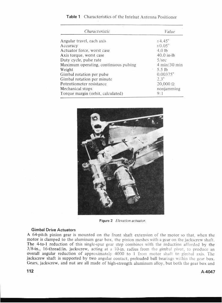
Table 1 Characteristics of the Intelsat Antenna Positioner
Characteristic Value
Angular travel, each axis k4.45" Accuracy t0.05" Actuator force, worst case 4.0 lb Axis torque, worst case 40.0 in-lb Duty cycle, pulse rate 5/sec Maximum operating, continuous pulsing 4 min/30 min Weight 5.5 lb Gimbal rotation per pulse 0.00375' Gimbal rotation per minute 2.3" Potentiometer resistance 20,000 R Mechanical stops nonjamming Torque margin (orbit, calculated) 9: 1
Figure 2 Elevation actuator.
Gimbal Drive Actuators A 64-pitch pinion gear is mounted on the front shaft extension of the motor so that, when the motor is clamped to the aluminum gear box. the pinion meshes with a gear on the jackscrew shaft. The 4-to-1 reduction of this single-spur gear step combines with the reduction afforded by the 3/8-in., 16-thread/in. jackscrew, acting at a 10-in. radius from the gimbal pivot. to produce an overall angular reduction of approximately 4000 to 1 from motor shafr to ginibal axis. The jackscrew shaft is supported by two angular contact, preloaded ball bearings within the gear box. Gears, jackscrew, and nut are all made of high-strength aluminum alloy, but both the gear box and
112 A-4047
CI I
nut holder are equipped with hardened steel pins that pivot in precision holes in their respective supporting aluminum structures. Figure 2 shows the location of the linear potentiometer used for position signal in the actuator. The potentiometer shaft is coupled to the wiper block with a built-in universal joint that absorbs misalinement throughout the stroke of the actuator.
Bearings and Lubrication The motor rotor and jackscrew shaft are supported by 440C CRES ball bearings with Duroid@ ball retainers. All metal parts of the bearings are burnished with high-purity molybdenum disulfide prior to assembly, and are run in and cleaned following assembly. These processes are performed using empirically determined techniques under carefully controlled conditions. Other pivotal points having angular rotations of less then IO" are journal bearings. The mating surfaces in these bearings have bonded solid lubricant burnished to a thin film of nominally 0.0003 in. thick. The same lubricating treatment is applied to the jackscrews and nuts. Except for journals at the principal gimbal pivot axes, all journals are steel pins. The gimbal pivots are larger in diameter and are made of aluminum tubing. Mounting and retaining features for these journals provide for differential expansiori or cijiiiractbn of the major structural e!ements of the positioner so that large thermal gradients can be tolerated without binding o r warping the assembly.
Structure The antenna support (outer gimbal member) requires high strength and stiffness since it spans the antenna mounting points and joins the load to the gimbal axes. The major portion of this element is machined from 7075T651 aluminum alloy plate. The U-section of this machined piece is made a box sec t inn by riveting and bonding a cover plate to its flanges. These measures ensure high stiffness and strength-to-weight ratios. Other structural elements, the inner gimbal member (cross), the support arm for the elevation actuator, the yoke, and the azimuth actuator support bracket are also machined from aluminum plate with webs, channels, and gussets to provide the necessary strength and stiffness at low weight penalty.
Position Indicator A linear potentiometer was chosen to indicate largely because it could provide position signals with a minimum of electronic complication at the interface with the telemetry system. The potentiometer contains a resistive element with homogeneous resistive properties embedded in a plastic substrate, thereby providing infinite resolution and greatly minimizing wear and debris problems. Redundant Paliney 7 ' contacts wipe the resistance element. A calibration curve is provided for each potentiometer and is referenced to the positioner axis and spacecraft so that ground stations will obtain precise position information.
PROBLEMS AND SOLUTIONS
Gimbal Pivots The positioner was originally designed to employ flexures at the gimbal pivot points, a feature that would have eliminated four sources of coulomb friction and clearances contributing to pointing error. The engineering unit was built using a popular brand of commercially available flex pivots, and the chosen size provided ratings with considerable margin for the limited angular excursion and low number of cycles. Failure of the pivots occurred during the first vibration test and was attributed to stress risers inherent in the pivot design.
Conideration was given to redesigning the pivot to exclude the stress risers, but delivery of the improved units was prohibitive. At this point detailed design parameters for dry lubricated journals were established for the gimbal pivots. Following an analytical study and verification test program they were adopted and have been completely satisfactory, as evidenced by successful accom- plishment of qualification-level vibration tests and performance of positioners in the spacecraft environmental test program.
A-4047 113

Holding Force The first positioners were built without electromagnetic brakes on the drive motors, and some assemblies had even been delivered and installed on spacecraft in this form. The motor drive commands were discrete square wave pulses of 100-msec duration at the rate of five pulses per sec. Since the motor is of the variable-reluctance type, with no magnetic field during the OFF portion of the command pulse, there is no detenting action on the motor rotor. The irreversible jackscrew was intended t o provide position control when the motor was not powered. During launch, when vibration would be present, it was planned to power the motor with a quiescent current to provide a holding force. After some period of testing, it was observed that the gimbal travel registered by the position indicator did not always agree with the travel that should have occurred with the number oE commanded motor steps. This phenomenon occurred only during thermal-vacuum tests and defied duplication in ambient conditions when observation was convenient. Finally, it was revealed that the coefficient of friction of the dry lubricated surfaces on the jackscrew and nut had improved with running and was in the vicinity of 0.055, which is the tangent of the helix angle of the jackscrew. This condition prevailed in vacuum, but a coefficient of approximately 0.2 is nominally experienced in atmosphere. Clearly, the overhanging load under conditions of Earth gravity was occasionally backdriving the actuator during the momentary interruptions of motor pulses.
This problem could have been corrected with unloading devices for testing in the presence of gravity or by revising the profile of electrical pulses supplied to the motor. Another solution in the form of a positive-acting magnetic brake was deemed advisable in view of the critical function of the positioner in a static sense. Hence, a highly accelerated development effort was applied, and assemblies with brakes were delivered within 5 weeks.
The problems cited above are not the only ones encountered, but others were less significant and were solved with relatively minor effort.
CONCLUSIONS
An account of the design and development of a relatively complex space mechanism has been provided. Success of the development has been demonstrated through an accomplished qualification test program and achievement of flight status. Eighteen assemblies have been manufactured and have passed their acceptance tests. The antenna positioner for Intelsat IV provides precise pointing of the high-gain antennas, as well as a strong structural support during a severe launch environment.
Within the mechanism a number of basic mechanical elements have been combined and successfully lubricated with methods based on molybdenum disulfide. These are:
1. 2. 3. 4. 5.
Ball bearings (motor shaft, jackscrew shaft) Spur gears (4: 1 reduction from motor to screw shaft) Jackscrew and nut (threads of screw and nut) Steel pivots in aluminum (actuator and nut pivots) Aluminum journals in aluminum (gimbal bearings)
A coefficient of friction of less than 0.055 was demonstrated on dry-lubricated surfaces operating in vacuum by following special burnishing and run-in procedures.
A highly efficient and lightweight electromagnetic brake adds measurably to the reliability and confidence level of the positioner. Since the function of the antenna positioner is, above all, to hold its preset position, the brake plays a very important role. Although the Intelsat IV antenna positioners may never be called on to move the antennas they support, their capabilities greatly augment the systems capability of the satellite.
ACKNOWLEDGEMENTS
This paper is based on work performed under the sponsorship of the International Telecommunica- tions Satellite Consortium (Intelsat). The views expressed in this paper do not necessarily reflect the views of Intelsat.
114 A-4047

DlSCUSSiON G. Eierzl; You mentioned that tile design specifications called foi 7-yeai lifetime, but that you set yourself a design goal of a 10-ycar lifetime. What did you do differently for the 10-year lifetime than you would have done for 7 years?
Author: This was a design criterion that applied to the entire spacecraft and is most important where consumables are involved or wear is significant. Very little was done differently in the case of the positioner other than to conduct endurance tests to show an operational margin for the equivalent of 10 years.
W. D. Wade: What special precautions or what doubts did you have in light of the 1 0-year design life?
Atithor: Our major concern centered on the potentiometer, which initially exhibited a weakness at low temperature. A design improvement was implemented to correct the problem. The position signals from the potentiometer are backed up by the ability to count steps applied to the stepper motors and the measurement of radiated signal strength at ground receiving stations.
Lee Hanon: Wire-wound potentiometers were used on Surveyor, while conductive plastic potentiometers were used on Intelsat IV. Were the two selected for different reasons, or to meet different constraints, or was the selection of plastic potentiometers in the later spacecraft a result of technological developments in the interim?
Author: The selection for Surveyor was influenced by program constraints, standardizatkn of cwnponents, and the short life in space. The selection for Intelsat IV wit4 influenced by the availability of linear potentiometers with plastic composite elements having the correct length of travel, the desired resolution, and the long life required in space.
Lee Hanon: Were any problems encountered in the use of plastic potentiometers in the space environment, such as outgassing, wear versus wiper pressure, o r changes in linearity due t o wear?
Author: None of the problems cited was encountered, but a mechanical problem involving differential thermal expansion was uncovered and solved. See the answer t o W. D. Wade’s question.
Don Kirkpatrick: In the selection of your drive motor, you selected a hysteresis stepper motor and brake t o provide torque for both driving and holding as opposed to the use of a permanent magnet stepper motor, which would provide both because the former motor was “space qualified.” To what level do you qualify individual components as opposed to qualifying overall mechanisms? What do you consider t o be justifiable tradeoffs between previous space application and suitability for use of a component in a new design when a functionally more suitable but not-qualified-by-your-firm component exists?
A-4047 115
116
Author: The original design of the positioner did not include brakes on the motors. The jackscrew in the reduction system was expected t o be irreversible, and a quiescent current in the motor during the brief period of launch vibration would have ensured positive holding. The fact that the motor had been previously qualified as a component by our company was a bonus and not an overriding factor in the selection. The brake was an added feature following the observance of some missed steps during thermal-vacuum tests in a 1-g gravity field. The addition of the brake was an overkill of the problem which could have been solved by using an unloading fixture for testing on the earth or by changing the form of motor pulses. Our company normally requires formal qualification of all components. Exceptions may occur when the component is so special that its use in other designs is unlikely. The overall mechanism is also qualified.
Don Kirkpatrick; Please discuss the materials, surface, treatments, lubricants, and clearances used in the journal bearings. a h well as the rationale for their selection.
Author: Much of the answer to this question is contained in the written paper but was not covered in detail during the oral presentation because of limited time. A complete answer would amount t o another technical paper, and in lieu of that the following references are cited which elaborate on the lubrication subject: (1 ) “Influence of Load, Speed, and Coating Thickness o f the Wear Life of Bonded Solid Lubricants,”C. J . Bahun and J . R. Jones, Lubrication Engineering (ASLE), September 1969; (2) “Neve Errentnisse Uber Die Wirkungsweise von Molydbiindisulfid als Schmierstoff, ” J. Gansheimer, Schmiertechnik, November 1964; and ( 3 ) “Some Effects o f Oscillatory Motion On Bonded Solid Lubricants,” A. DiSapio and F. Lindsey, Lubrication Engineering, November 1970.
Gordon S. Pistole: If you had sufficient time, d o you believe a redesigned flexural pivot approach could be made t o d o the design job better (consider lower cost, simplicity, friction, schedule, reliability) than the approach that was used in your positioner?
Author: We believe a flexural pivot approach that would withstand the vibration environment is preferable t o journal bearings for reasons of simplicity, absence of coulomb friction, and elimination of clearances.
Gordon S. Pistole: Would you supply some additional detail on the flexural pivot that failed and why?
Author: The flexural pivot that failed is Bendix PIN 5016-600 ( 1 i 2 in. cantilever type). The pivot has a spring rate of 6.54 in.-lb per rad and a deflection capability of k15”. The rated radial load capacity is 141 lb. Failure occurred during vibration at the junction between blades of the flexure and the cylindrical supporting members. The failure was characterized as a fatigue fracture.
A-4047
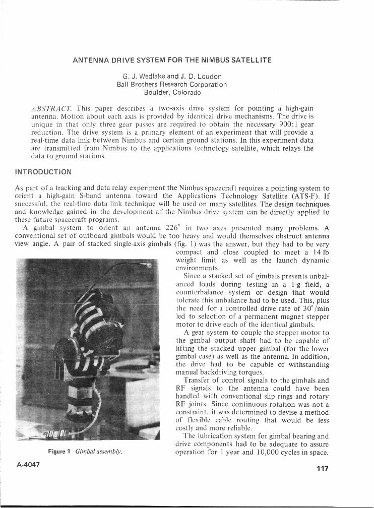
ANTENNA DRIVE SYSTEM FOR THE NIMBUS SATELLITE
G. d. Wedlake and ?. D. Leudon Ball Brothers Research Corporation
Boulder, Colorado
ABSTRACT. This paper describes a two-axis drive system for pointing a high-gain antenna. Motion about each axis is provided by identical drive mechanisms. The drive is unique in that only three gear passes are required to obtain the necessary 900:l gear reduction. The drive system is a primary element of an experiment that will provide a real-time data link between Nimbus and certain ground stations. In this experiment data are transmitted from Nimbus to the applications technology satellite, which relays the data to ground stations.
INTRODUCTION
As part of a tracking and data relay experiment the Nimbus spacecraft requires a pointing system to orient a high-gain S-band antenna toward the Applications Technology Satellite (ATS-F). If successful, the real-time data link technique will be used on many satellites. The design techniques and knowiedge gained in t h e bevdopmeni of the Nimbus drive system can be direct!y ~pp!kd t o these future spacecraft programs.
A gimbal system t o orient an antenna 226" in two axes presented many problems. A conventional set of outboard gimbals would be too heavy and would themselves obstruct antenna view angle. A pair of stacked single-axis gimbals (fig. 1) was the answer, but they had to be very
Figure 1 Gimbal assembly.
A4047
compact and close coupled to meet a 14 Ib weight limit as well as the launch dynamic environments.
Since a stacked set of gimbals presents unbal- anced loads during testing in a I-g field, a counterbalance system or design that would tolerate this unbalance had t o be used. This, plus the need for a controlled drive rate of 30"/min led to selection of a permanent magnet stepper motor to drive each of the identical gimbals.
A gear system to couple the stepper motor to the gimbal output shaft had to be capable of lifting the stacked upper gimbal (for the lower gimbal case) as well as the antenna. In addition, the drive had to be capable of withstanding manual backdriving torques.
Transfer of control signals t o the gimbals and RF signals to the antenna could have been handled with conventional slip rings and rotary RF joints. Since continuous rotation was not a constraint, it was determined to devise a method of flexible cable routing that would be less costly and more reliable.
The lubrication system for gimbal bearing and drive components had to be adequate to assure operation for 1 year and 10,000 cycles in space.
117
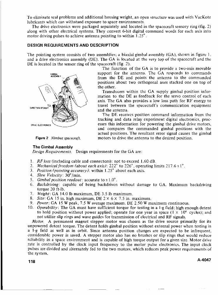
To eliminate seal problems and additional housing weight, an open structure was used with VacKote lubricants which can withstand exposure to space environments.
The drive electronics were packaged separately and located in the spacecraft sensory ring (fig. 2) along with other electrical systems. They convert 6-bit digital command words for each axis into motor driving pulses to achieve antenna pointing to within 1.25".
DESIGN REQUIREMENTS AND DESCRIPTION
The pointing system consists of two assemblies; a biaxial gimbal assembly (GA), shown in figure 1 , and a drive electronics assembly (DE). The GA is located at the very top of the spacecraft and the DE is located in the sensor ring of the spacecraft (fig. 2).
The function of the GA is to provide a two-axis movable support for the antenna. The GA responds to commands from the DE and points the antenna to the commanded positions about two orthogonal axes stacked one on top of the other.
Transducers within the GA supply gimbal position infor- mation to the DE as feedback for the servo control of each axis. The GA also provides a low loss path for RF energy to travel between the spacecraft's communication equipment and the antenna.
The DE receives position command information from the tracking and data relay experiment digital electronics, proc- esses this information for powering the gimbal drive motors, and compares the commanded gimbal positions with the actual positions. The resultant error signal causes the gimbal motors to drive the antenna to the desired position.
DIRECTION OFORBIT
DRIVE ELECTRONICS
Figure 2 Nimbus spacecraft.
The Gimbal Assembly Design Requirements. Design requirements for the GA are:
1. RF loss (including cable and connectors): not to exceed 1.60 dB. 2. Mechanical freedom (about each axis): 222" to 226", operating limits 2 17.6 k 1". 3 . Position (pointing accuracy): within 1.25" about each axis. 4. Slew Velocity: 30°/min. 5 . Gimbal position readout: accurate to ?I 1 .O". 6 , Backdriving: capable of being backdriven without damage to GA. Maximum backdriving
torque 20 ft-lb. 7. Weight: GA 14.0 lb maximum, DE 3.5 lb maximum. 8. Size: GA 15 in. high maximum, DE 2 X 6 X 7.5 in. maximum. 9. Power: GA 15 W peak, 7.5 W average maximum. DE 2.50 W maximum continuous.
10. Operability: The GA must have sufficient torque for testing in a 1-g field; high enough detent to hold position without power applied; operate for one year in space (1 X 1 O4 cycles); and not utilize slip rings and wave guides for transmission of electrical and R F signals.
Motor. A permanent magnet stepper motor was chosen as the drive source primarily for its unpowered detent torque. The detent holds gimbal position without external power when testing in a 1-g field as well as in orbit. Since antenna position changes are expected to be infrequent, considerable power is saved. A stepper motor also has no brushes or slip rings that would reduce reliability in a space environment and is capable of high torque output for a given size. Motor drive rate is controlled by the clock input frequency t o the motor pulse electronics. The input clock pulses are divided and alternately fed to the two motors, which reduces peak power requirements of the system.
118 A-4047
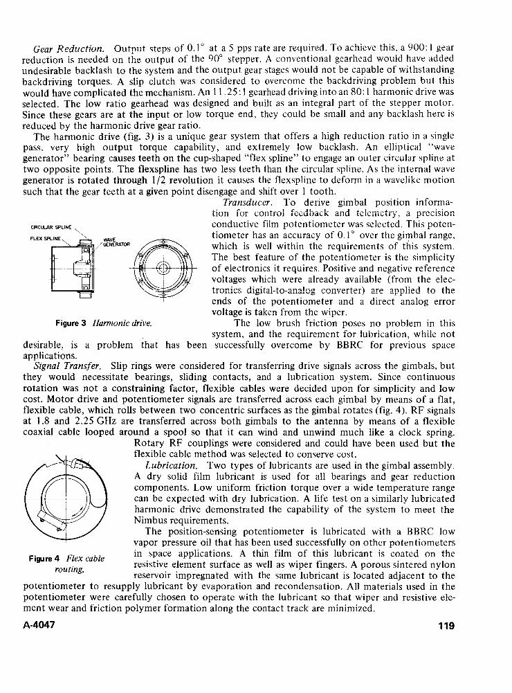
Gear A?edzrction. Output steps of 0.1” at a 5 pps rate are required. To achieve this, a 900: 1 gear rediIction is needed 3n the outpi,lt of the 90” stepper. A conventional gearhead would have added undesirable backlash to the system and the output gear stages would not be capable of withstanding backdriving torques. A slip clutch was considered t o overcome the backdriving problem but this would have complicated the mechanism. An 1 1.25: 1 gearhead driving into an 80: 1 harmonic drive was selected. The low ratio gearhead was designed and built as an integral part of the stepper motor. Since these gears are at the input or low torque end, they could be small and any backlash here is reduced by the harmonic drive gear ratio.
The harmonic drive (fig. 3) is a unique gear system that offers a high reduction ratio in a single pass, very high output torque capability, and extremely low backlash. An elliptical “wave generator” bearing causes teeth on the cup-shaped “flex spline” to engage an outer circular spline at two opposite points. The flexspline has two less teeth than the circular spline. As the internal wave generator is rotated through 1/2 revolution it causes the flexspline to deform in a wavelike motion such that the gear teeth at a given point disengage and shift over 1 tooth.
Transducer. T o derive gimbal position informa- tion for control feedback and tekmetrj.’, a prccxon conductive film potentiometer was selected. This poten- tiometer has an accuracy of 0.1” over the gimbal range, which is well within the requirements of this system. The best feature of the potentiometer is the simplicity of electronics it requires. Positive and negative reference voltages which were already available (from the elec- tronics digita!-te-ar?a!og c ~ f i v e r t e r ) are app!ied to the ends of the potentiometer and a direct analog error voltage is taken from the wiper.
The low brush friction poses no problem in this system, and the requirement for lubrication, while not
desirable, is a problem that has been successfully overcome by BBRC for previous space applications.
Slip rings were considered for transferring drive signals across the gimbals, but they would necessitate bearings, sliding contacts, and a lubrication system. Since continuous rotation was not a constraining factor, flexible cables were decided upon for simplicity and low cost. Motor drive and potentiometer signals are transferred across each gimbal by means of a flat, flexible cable, which rolls between two concentric surfaces as the gimbal rotates (fig. 4). RF signals at 1.8 and 2.25 GHz are transferred across both gimbals to the antenna by means of a flexible coaxial cable looped around a spool so that it can wind and unwind much like a clock spring.
Rotary RF couplings were considered and could have been used but the flexible cable method was selected to conserve cost.
Lubrication. Two types of lubricants are used in the gimbal assembly. A dry solid film lubricant is used for all bearings and gear reduction components. Low uniform friction torque over a wide temperature range can be expected with dry lubrication. A life test on a similarly lubricated harmonic drive demonstrated the capability of the system to meet the Nimbus requirements.
The position-sensing potentiometer is lubricated with a BBRC low vapor pressure oil that has been used successfully on other potentiometers in space applications. A thin film of this lubricant is coated on the resistive element surface as well as wiper fingers. A porous sintered nylon reservoir impregnated with the same lubricant is located adjacent to the
potentiometer to resupply lubricant by evaporation and recondensation. All materials used in the potentiometer were carefully chosen to operate with the lubricant so that wiper and resistive ele- ment wear and friction polymer formation along the contact track are minimized.
A-4047 119
. .
CIRCULAR SPLINE , FLEX WAVE
GENERATIF4
Figure 3 Harmonic drive.
Signal Transfer.
Figure 4 Flex cable routing.

The Drive Electronics Assembly The control electronics package receives a 6-bit digital command word for each of the two gimbal axes. A digital-to-analog converter consisting of a thin-film ladder network and integrated circuit ladder switches generates an analog position reference voltage for each axis. This reference is compared with the potentiometer wiper voltage to give a position error signal. Error level detectors have a built-in dead zone so that a 0.2" error must occur before corrective drive pulses are fed to the stepper motor. The motor will then continue to drive until the error is reduced to less than 0.1".
An internal power supply provides necessary voltages for operating linear and digital electronics from 28 V DC spacecraft power. The electronics package also conditions several monitor items such as supply voltages, gimbal and electronics temperature, gimbal position, and gimbal error for telemetry.
CONCLUSION
An engineering model of the pointing system was built and thoroughly tested. Environmental tests on this unit included vibration, thermal vacuum performance, and shock. Environmental test levels were equal to those required to qualify the system. Actual performance of the system was found to meet or exceed all the design requirements outlined earlier. Absolute pointing accuracy is less than 0.5" in each axis, much better than the 1.25" requirement. Measured RF loss is 1.20 dB as compared t o the 1.60 dB design requirement. Gimbal position readout is accurate to better than O S " , twice the required accuracy.
The engineering model was delivered to General Electric and successfully tested with the Nimbus structural model and found to be compatible with vibration inputs to the spacecraft. A qualification model was built, tested and delivered as a flight spare. Subsequently, a flight model was built, tested and delivered for integration into the Nimbus E spacecraft.
120 A-4047
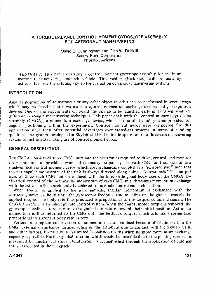
A TORQUE BALANCE CONTROL MOMENT GYROSCOPE ASSEMBLY FOR ASTRONAUT MANEUVERING
David C. Cunningham and Glen W. Driskill Sperry Rand Corporation
Phoenix, Arizona
ABSTRACT. This paper describes a control moment gyroscope assembly for use in an astronaut maneuvering research vehicle. This vehicle (backpack) will be used by astronauts inside the orbiting Skylab for evaluation of various maneuvering systems.
INTRODUCTION
Angular positioning of an astronaut or any other object in orbit can be performed in several ways which may be classified into two main categories; momen turn-exchange devices and gas-expulsion devices. One of the experiments on board the Skylab to be launched early in 1973 will evaluate different astronaut maneuvering techniques. This paper deals with the control moment gyroscope assembly (CMGA), a momentum exchange device, which is one of the subsystems provided for angular positioning within the experiment. Control moment gyros were considered for this application since they offer potential advantages over stored-gas systems in terms of handling qualities. The system developed for Skylab will be the first in-space test of a three-axis maneuvering system for astronauts making use of control moment gyros.
GENERAL D ESCR I PTlON
The CMGA consists of three CMG units and the electronics required to drive, control, and monitor these units and to provide power and telemetry output signals. Each CMG unit consists of two single-gimbal control moment gyros, which are mechanically coupled as a “scissored pair” such that the net angular momentum of the unit is always directed along a single “output axis.” The output axzs of three such CMG units are alined with the three orthogonal body axes of the CMGA. By e!i.ctrjcal control of the net angular momentum of each CMG unit, three-axis momentum exchange wi th the aslronaut/backpack body is achieved for attitude control and stabilization.
When torque is applied to the gyro gimbals, angular momentum is exchanged with the astroi:aut/baclipa~k body until the gyroscopic feedback torque acting on the gimbals cancels the applied torque. The body rate thus produced is proportional t o the torquer command signals. The C 3 G A t1:t‘reioi-c is an inherent rate control system. When the gimbal motor torque is removed, the g).roscopic teedback torque causes the gimbals t o return toward their initial position. Astronaut momentum is thus returned to the CMG until the feedback torque, which acts like a spring load proportional to aaironaut body rate, is zero.
Perfect or complete conservation of momentum is not obtained because of friction within the CMG, external disturbance torques acting on the astronaut due to contact with the Skylab walls, and criier factors. Eventually, a “saturated” condition results when no more momentum exchange capacity is possiblc. Further gimbal rotation, which would be unstable due to the phasing reversal, is prevented by mechanical stops. Desaturation is accomplished through the application of cold gas thruilers located in the backpack.
A-4047 121

SINGLE-AXIS CONTROL SYSTEM
o D E R I V E D G I M B A L R A T E ~ , - --------------- -
I I N T E G R A L I
The basic control loop for a single gyro is shown in figure 1. The input voltage Es commands a current of Es/KI~ through the high-gain current loop. The current loop provides for a constant gain between the stick command voltage and the torquer current IM for bus voltage variations of 24 to 32 Vdc. In addition, voltage offsets inside the power amplifier are cancelled by the integrator to prevent their appearing as extraneous gimbal torques.
ES STICK COMMAND VOLTAGE
EA POWER AMPLIFIER OUTPUT VOLTAGE
lM TOROUER CURRENT
TM MOTOR TOROUE
TL GYROSCOPIC L O A D TORDUE
( I G I M B A L RATE o G I M B A L ANGLE T v CMG OUTPUT TORDUE
TD EXTERNAL DISTURBANCE TOROUE
ZHClnl I
GYROSCOPIC TOROUE G A I N
Figure 1 Simplified gimbal loop block diagram
Since the gyroscope feedback torque varies with the cosine of the gimbal angle, the torque motor gain is designed to have a similar cosine function characteristic. When a torque balance (steady state) condition is reached, the astronaut rate is linearly related to the stick command voltage. More important, however, torquer cosine conformity is necessary to prevent loss of control at gimbal angles greater than 45" due to a net decrease in load torque with increasing gimbal angle.
Damping of the gyro/astronaut momentum exchange system is provided by gimbal rate feedback to the torquer. Derived rate is used rather than a tachometer to minimize gimbal friction. A position feedback is also provided on command for caging the gyro.
THE CMG UNIT
Functional Description An isometric mechanical schematic of the CMG is given in figure 2 along with its gimbal axis system. The input axis (IA) is parallel with the gyro gimbal axes, and the gyro spin reference axis
122 A-4047

--
GIMBAL ASSV ' I "
GIMBAL A S Y " T
MOUNTING PLANE
>cat 'SIIZ
Figure 2 Mechanical schematic of the CMG unit.
is p i a i l e l with thc gyro momcfitua vectors when they are at zero gimbal angle. The output axis (OA) is mutu- ally perpendicular to the IA and SRA such that the IA, OA, and SRA, respectively, form a right-hand coord- inate system as shown. The reference directions for the gimbal angles are also indicated.
The two gyros, which are of identi- cal design, are positioned with the spin axes nominally colinear. Each gimbal is suspended in low-torque, instrument-grade ball bearings. A limi- ted-angle brushless DC torque motor acts about each gimbal axis to rotate the gyro pair. A wide-range linear induction potentiometer is mounted on the axis of one gimbal and provides accurate gimbal angle information to the CMG control subsystem. A caging device, which is self-detenting in both the caged and uncaged positions, is provided to lock the gimbal pair at the pickoff null position; it is actuated by external command. Continuity signals
are provided to indicate the state of the caging mechanism. T o eliminate the need for sliding electrical contacts, the leads from each gimbal are brought out to the frame through flex lead capsules. Isolated gimbal grounds are provided for the gimbal assemblies and frame to minimize the generation of RFI within the gyro unit.
Physical Description The CMG is designed to provide the required performance and reliability at the lowest practical weight. It also is hermetically sealed for maximum environmental resistance. Mounting to the base plate is accomplished with four bolts; an asymmetrical dowel pin hole pattern provides accurate alinement of the gyro axes and also prevents improper installation. A breakdown of the CMG is shown in figure 3.
Housing. The frame of the CMG is of one-piece machined construction for maximum strength and optimum sealing characteristics; critical mounting geometry is machined in one setup. Calibration adjustments are accessible and all functional components are in place before the covers are soldered on each side.
The CMG becomes a fully hermetically sealed unit after the covers are soldered to the mating surfaces of the case. A pinch-off tube is soldered t o the housing and is used for leak checking to verify integrity of the hermetic seal. The unit is filled with helium gas at 6 to 10 psia to provide the inert atmosphere necessary to prolong bearing lubricant life and to improve heat transfer from the gimbal housings t o the CMG housing. The gimbal assemblies are separately sealed and filled with helium since they require a constant lower pressure environment t o reduce gyro rotor windage drag torques.
The CMG unit is mounted by a rugged flange, which is machined as part of the main case. The same machine setup is used for machining of the mounting surfaces, the bearing bore location, and torquer mounting bores. This procedure ensure accurate alinement of all CMG axes to the mounting plane.
A-4047 123

---+e2 BEARING RETAINER
BEARING ---
BELLfVILLE SPRING
BEARING A N 0 STATOR MOUNTlNG - PLATE
STATOR MOUNTING
ANGULAR POSITION <a -:-I AN6ULAR PDSiTlON P l C l O F F ROTUR
ROTOR SPEED
CI I t lBAL *SSt*1BLV -~
,-
I )
I .' L,,'
,- ,
,
I'
1
I LECTRICAL CONNECTOR
C A S
B f ARI 4 6
BEARI L R t T A l \ E R
~ ' I U l PRELOAD GIMBAL CAGING S O L f NOID
B f ARI 4 6
BEARI L R t T A l \ E R
~ ' I U l PRELOAD GIMBAL CAGING S O L f NOID
TEAR BAND
'tu1 TOROUt MOTOR ROTOR PEThINFR
- TOROUE MOTOR STATOR
COV€ R '
/,N 1 I. , < ,
Figure 3 The CMG unit.
Materials. The frame material is 6061-T6 aluminum because of its good heat transfer, low weight, and high strength, The gimbals are 17-4 PH stainless steel because of its high strength and the necessity to match the thermal coefficient of the rotor and bearings. Nonmetallic materials used in the CMG unit are stable, low outgassing type epoxy compounds; they are required t o impregnate the electrocomponent windings and to cement parts together in low stress joints. The epoxy adhesive used for gyro joint cementing is Bacon Industries LCA-4, which is a gyro grade adhesive developed for high stability, good sealing qualities, and a thermal expansion coefficient close to that of aluminum.
Gimbal Assemblies. Each of the two gimbal assemblies consists of a rotor driven at approximately 22,000 rpm by a two-phase induction motor driven off a 400-Hz variable duty cycle square wave supply contained within the CMG assembly. The angular momentum of each rotor is approximately 1 ft-lb-sec, and the run-up time of each rotor is 20 min to 20,000 rpm. The rotor bearings are of the same basic design as the gimbal bearings but their lubricant is compatible with the higher speed. These bearings were developed by the Barden Corporation for a gyroscope that operates in a missile environment, and they have the necessary load capacity to withstand the high torsional loading gyroscopically induced by the high gimbal rates that may occur during the CMG operation. The rotor assembly is sealed in a 0.5 in. Hg (0.25 psi) absolute pressure to minimize the rotor windage and hence the steady-state operating power. Rotor speed is sensed by a pickup that
1 24 A-4047
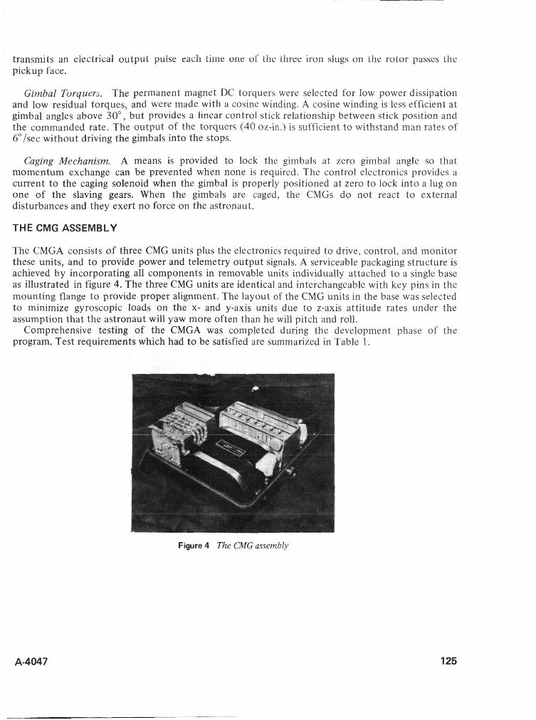
transmits an eiectrical output puise each time one of the three iron slugs on the rotor passes the pickup face.
Gimbal Torquers. The permanent magnet DC torquers were selected for low power dissipation and low residual torques, and were made with a cosine winding. A cosine winding is less efficient at gimbal angles above 30", but provides a linear control stick relationship between stick position and the commanded rate. The output of the torquers (40 oz-in.) is sufficient to withstand man rates of 6"/sec without driving the gimbals into the stops.
a g i n g Mechanism. A means is provided to lock the gimbals at zero gimbal angle so that momentum exchange can be prevented when none is required. The control electronics provides a current to the caging solenoid when the gimbal is properly positioned at zero to lock into a lug on one of the slaving gears. When the gimbals are caged, the CMGs do not react to external disturbances and they exert no force on the astronaut.
THE CMG ASSEMBLY
The CMGA consists of three CMG units plus the electronics required to drive, control, and monitor these units, and to provide power and telemetry output signals. A serviceable packaging structure is achieved by incorporating all components in removable units individually attached to a single base as illustrated in figure 4. The three CMG units are identical and interchangeable with key pins in the mounting flange to provide proper alignment. The layout of the CMG units in the base was selected to minimize gyroscopic loads on the x- and y-axis units due to z-axis attitude rates under the assumption that the astronaut will yaw more often than he will pitch and roll.
Comprehensive testing of the CMGA was completed during the development phase of the program. Test requirements which had to be satisfied are summarized in Table 1.
Figure 4 The CMG assembly
A-4047 125
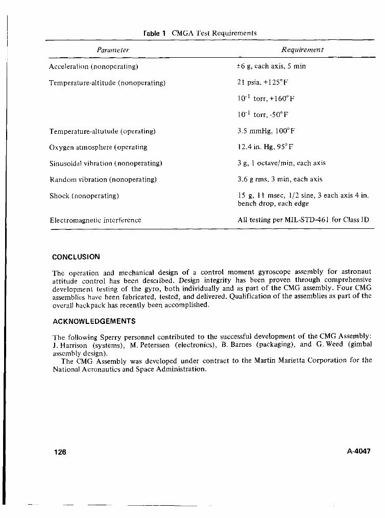
rable 1 CMGA Test Requirements ~~
Requirement
Acceleration (nonoperating)
Temperature-altitude (nonoperating)
Temperature-altutude (operating)
Oxygen atmosphere (operating
Sinusoidal vibration (nonoperating)
Random vibration (nonoperating)
Shock (nonoperating)
Electromagnetic interference
26 g, each axis, 5 min
2 1 psia, + 125" F
IO-' torr, + 160" F
lo-' torr, -50°F
3.5 mmHg, 100°F
12.4 in. Hg, 95" F
3 g, 1 octave/min, each axis
3.6 g rms, 3 min, each axis
15 g, 1 1 msec, 1/2 sine, 3 each axis 4 in. bench drop, each edge
All testing per MIL-STD-461 for Class ID
CONCLUSION
The operation and mechanical design of a control moment gyroscope assembly for astronaut attitude control has been desciibed. Design integrity has been proven through comprehensive development testing of the gyro, both individually and as part of the CMG assembly. Four CMG assemblies have been fabricated, tested, and delivered. Qualification of the assemblies as part of the overall backpack has recently been accomplished.
ACKNOWLEDGEMENTS
The following Sperry personnel contributed to the successful development of the CMG Assembly: J. Harrison (systems), M. Peterssen (electronics), B. Barnes (packaging), and G. Weed (gimbal assembly design).
The CMG Assembly was developed under contract to the Martin Marietta Corporation for the National Aeronautics and Space Administration.
126 A-4047
A SOLID-STATE FILM TRANSPORT
Charles M. Davis Teledyne Ryan Aeronautical
San Diego, California Donald 6. Learish, AFAL/RSO
Wright Patterson Air Force Base, Ohio
ABSTRACT. A solid state film transport utilizing piezoelectric motion has been evaluated and found to have definite potential in film positioning applications. The concept is particularly useful in flight equipment where torque motors and conventional transport mechanisms are frequently difficult to apply.
A demonstration model utilizing 5-inch film has been designed, tested and evaluated. Three basic operating modes were investigated with the following performance goals:
1. Triggered Steps 2. Free Running Stepping
3 . Continuous
1 pm to 1 0 p m in 1 pm increments 1 pm to lOpm 10 t o 100 steps/sec 1 t o 100mm/sec
Design goals for step size were achieved under controlled conditions. The continuous mode test results were marred by an inability to transfer efficiently the piezoceramic motion t o the film itself. This paper describes the design, test results, and problem areas, along with the considerations necessary t o make the piezoceramic film transport a realistic solution to several potential applications.
INTRODUCTlON
The aerospace community has a continuing and growing need for high-quality image recorders and film readers. Both applications require accurate and precise film transports. The imagery built up from a succession of evenly spaced scan lines often requires line placement accuracies of the order of one micrometer. The narrow line width capabilities of the new electron and laser beam recorders place additional demands on film transports.
The piezoceramic transport engages the film directly in the format region and literally carries it through the area of interest by means of the controlled expansion and compression of the piezoceramic elements. The overall result is a transport scheme of inherently high acceleration, low inertia, and flexibility. If the piezoceramic is expanded properly, the film can be moved as little as lp at a time. In contrast, a torque motor with a gear- or belt-driven capstan/pinch roller has difficulty moving the film this small amount.
The rotary motion for l p of transport is approximately equivalent t o 1 arcsec of angle. To move a capstan 1 arcsec, the torque motor may rotate as much as a degree. The necessary mechanical tolerances in the bearings, gears and positioning of the motor are very severe. In addition, the inertia of the motor, gears, and capstan can be much larger than that of several small pieces of ceramic material. This factor alone limits the performance of the torque motor a t high stepping rates.
,
A-4047 127
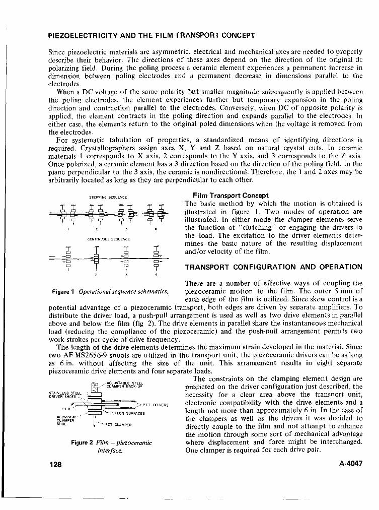
PIEZOELECTRICITY AND THE FILM TRANSPORT CONCEPT
Since piezoelectric materials are asymmetric, electrical and mechanical axes are needed t o properly describe their behavior. The directions of these axes depend on the direction of the original dc polarizing field. During the poling process a ceramic element experiences a permanent increase in dimension between poling electrodes and a permanent decrease in dimensions parallel to the electrodes.
When a DC voltage of the same polarity but smaller magnitude subsequently is applied between the pclina electrodes, the element experiences further but temporary expansion in the poling direction and contraction parallel to the electrodes. Conversely, when DC of opposite polarity is applied, the element contracts in the poling direction and expands parallel to the electrodes. In either case, the elements return to the original poled dimensions when the voltage is removed from the electrodes.
For systematic tabulation of properties, a standardized means of identifying directions is required. Crystallographers assign axes X, Y and Z based on natural crystal cuts. In ceramic materials 1 corresponds to X axis, 2 corresponds to the Y axis, and 3 corresponds to the Z axis. Once polarized, a ceramic element has a 3 direction based on the direction of the poling field. In the plane perpendicular to the 3 axis, the ceramic is nondirectional. Therefore, the 1 and 2 axes may be arbitrarily located as long as they are perpendicular to each other.
STEPPING SEQUENCE Film Transport Concept The basic method by which the motion is obtained is illustrated in figure 1 . Two modes of operation are illustrated. In either mode the clamper elements serve
I 2 3 4 the function of “clutching” or engaging the drivers to the load. The excitation to the driver elements deter- mines the basic nature of the resulting displacement
2 and/or velocity of the film. 2 T3
7 TRANSPORT CONFIGURATION AND OPERATION 7 7 There are a number of effective ways of coupling the piezoceramic motion to the film. The outer 5 mm of each edge of the film is utilized. Since skew control is a
potential advantage of a piezoceramic transport, both edges are driven by separate amplifiers. T o distribute the driver load, a push-pull arrangement is used as well as two drive elements in parallel above and below the film (fig 2). The drive elements in parallel share the instantaneous mechanical load (reducing the compliance of the piezoceramic) and the push-Dull arrangement permits two work strokes per cycle of drive frequency.
The length of the drive elements determines the maximum strain developed in the material. Since two AF MS2656-9 snools are utilized in the transport unit, the piezoceramic drivers can be as long as 6 in. without affecting the size of the unit. This arrangement results in eight separate piezoceramic drive elements and four separate loads.
The constraints on the clamping element design are predicted on the driver configuration just described, the necessity for a clear area above the transnort unit, electronic compatibility with the drive elements and a length not more than approximately 6 in. In the case of the clampers as well as the drivers i t was decided to directly couple to the film and not attempt to enhance the motion through some sort of mechanical advantage where displacement and force might be interchanged. One clamper is required for each drive pair.
CONTINUOUS SEOUENCE
c)- - 4 I
-0 -a - 4 7
I 2 3
Figure 1 Operational sequence schematics.,
PZT
PZT CLAMPER
Figure 2 Film - piezocerantic interface.
128 A-4047
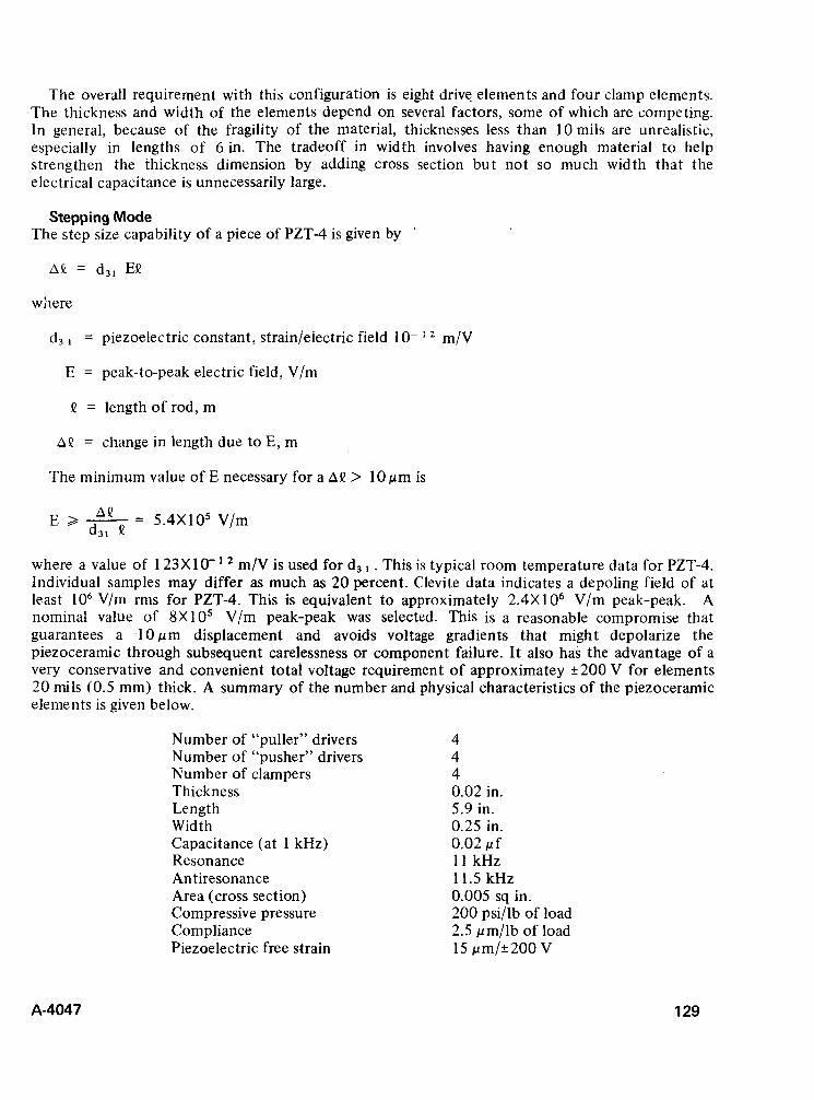
The overall requirement with this configuration is eight drive elements and four clamp elements. The thickness and width of the elements depend on several factors, some of which are competing. In general, because of the fragility of the material, thicknesses less than 10 mils are unrealistic, especially in lengths of 6 in. The tradeoff in width involves having enough material to help strengthen the thickness dimension by adding cross section but not so much width that the electrical capacitance is unnecessarily large.
Stepping Mode The step size capability of a piece of PZT-4 is given by
A Q = d,, E!?
where
d, = piezoelectric constant, strainieiectric fieid io- m/V
E = peak-to-peak electric field, V/m
!? = lengthof rod,m
na = change in length due to E, m
The minimum value of E necessary for a AQ > 10 pm is
E > - - “ - 5.4X10⁵ V/m d31 !?
where a value of 1 23X 10- ’ m/V is used for d3 . This is typical room temperature data for PZT-4. Individual samples may differ as much as 20 percent. Clevite data indicates a depoling field of at least IO6 V/m rms for PZT-4. This is equivalent to approximately 2.4X10⁶ V/m peak-peak. A nominal value of 8X10⁵ V/m peak-peak was selected. This is a reasonable compromise that guarantees a ‘ 1 0 p m displacement and avoids voltage gradients that might depolarize the piezoceramic through subsequent carelessness or component failure. I t also has the advantage of a very conservative and convenient total voltage requirement of approximatey f 200 V for elements 20 mils (0.5 mm) thick. A summary of the number and physical characteristics of the piezoceramic elements is given below.
Number of “puller” drivers Number of “pusher” drivers Number of clampers Thickness Length Width Capacitance (at 1 kHz) Resonance Antiresonance Area (cross section) Compressive pressure Compliance Piezoelectric free strain
4 4 4 0.02 in. 5.9 in. 0.25 in. 0.02 pf 1 1 kHz 11.5 kHz 0.005 sq in. 200 psi/lb of load 2.5 pm/lb of load 15 pm/* 200 V
A-4047 129
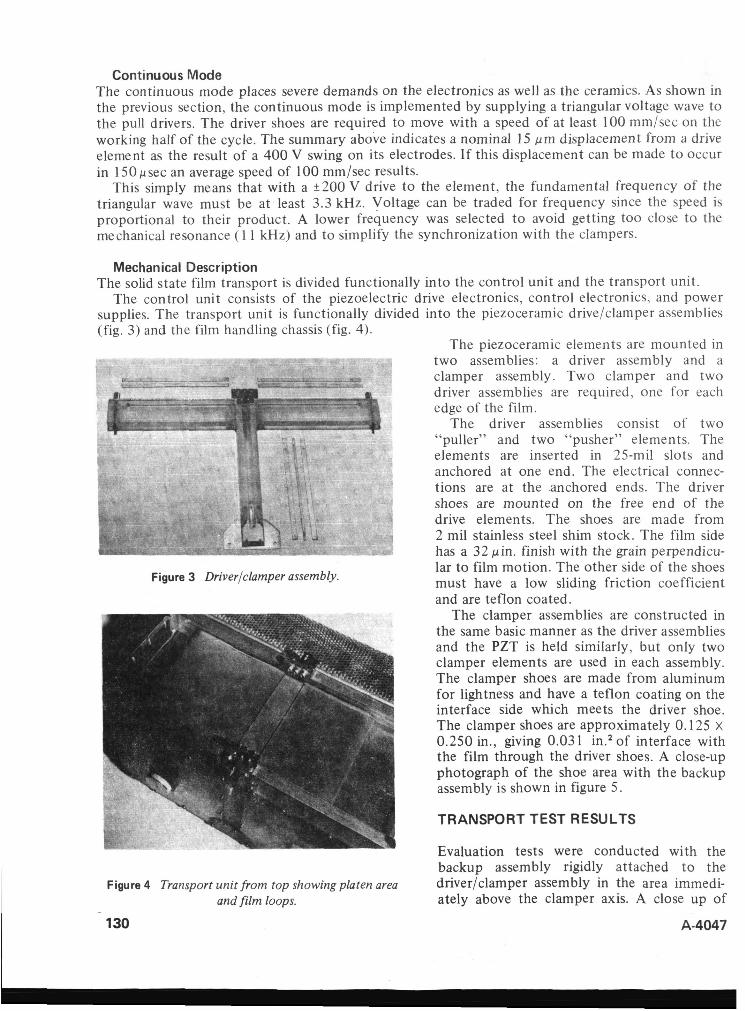
Continuous Mode The continuous mode places severe demands on the electronics as well as the ceramics. As shown in the previous section, the continuous mode is implemented by supplying a triangular voltage wave to the pull drivers. The driver shoes are required to move with a speed of at least 100 mmlsec on the working half of the cycle. The summary above indicates a nominal I5 pm displacement from a drive element as the result of a 400 V swing on its electrodes. If this displacement can be made t o occur in 150 psec an average speed of 100 mm/sec results.
This simply means that with a k200 V drive to the element, the fundamental frequency of the triangular wave must be at least 3.3 kHz. Voltage can be traded for frequency since the speed is proportional to their product. A lower frequency was selected to avoid getting too close to the mechanical resonance ( 1 1 kHz) and to simplify the synchronization with the clampers.
M ec han ical Description The solid state film transport is divided functionally into the control unit and the transport unit.
The control unit consists of the piezoelectric drive electronics, control electronics, and power supplies. The transport unit is functionally divided into the piezoceramic drive/clamper assemblies (fig. 3) and the film handling chassis (fig. 4).
The piezoceramic elements are mounted in two assemblies: a driver assembly and a clamper assembly. Two clamper and two driver assemblies are required, one for each edge of the film.
The driver assemblies consist of two “puller” and two “pusher” elements. The elements are inserted in 25-mil slots and anchored at one end. The electrical connec- tions are at the anchored ends. The driver shoes are mounted on the free end of the drive elements. The shoes are made from 2 mil stainless steel shim stock. The film side has a 32 pin. finish with the grain perpendicu-
Figure 3 Driverlclamper assembly. lar to film motion. The other side of the shoes must have a low sliding friction coefficient and are teffon coated.
The clamper assemblies are constructed in the same basic manner as the driver assemblies and the PZT is held similarly, but only two clamper elements are used in each assembly. The clamper shoes are made from aluminum for lightness and have a teflon coating on the interface side which meets the driver shoe. The clamper shoes are approximately 0.125 x 0.250 in., giving 0.03 1 in.’ of interface with the film through the driver shoes. A close-up photograph of the shoe area with the backup assembly is shown in figure 5 .
TRANSPORT TEST RESULTS
Evaluation tests were conducted with the backup assembly rigidly attached t o the driver/clamper assembly in the area immedi- ately above the clamper axis. A close up of
Figure 4 Transport unit from top showing platen area and film loops.
130 A-4047

the configuration is illustrated in the photograph in figure 5. The result is a so-called rigid back-up assembly. I t has the disadvantage of being sensitive to dimensional variations of the order of several pm in any of the elements in the clamper subsystem due to temperature, film thickness variation or depolarization of the PZT.
With a nominal 200 V on the system, 8.2 pm per step was realized at all of the stepping rates. By increasing the system voltage to 219 V (both dampers and drivers), the maximum step size was measured at 10.3 pm. Since the driver displacement is about 13 pm, there is still considerable loss of driver displacement due t o the insufficient clamper motion. This results in:
Figure 5 Closeup of backup assembly, shoes and film interface.
0 Inadequate ratio between ON and OFF clamping pressure (“OFF” pressure should be essentially zero).
0 Stretching and buckling of the film due to “drag” of the nonworking shoe.
The time constant of the drive circuit was increased from 40 psec to 4 msec to see if the loss in displacement could be due to slippage from too high accelerations. The step size was reduced essentially to zero by this modification. The time constant was returned to the initial value. The sudden movement (>9g) of the smaller time constant “breaks” the film free from the nonmoving shoe and is essential to the operation of the stepping mode as long as there is residual pressure (drag) in the system.
Testing of the Continuous Mode was more preliminary than that of the stepping mode since its performance had been compromised by the stepping mode considerations. The tests that were conducted indicated the driver shoes at the 100 mm/sec setting were moving at least 100 mmlsec (based on frequency and amplitude); however, this speed was not successfully transmitted to the film. The highest speed observed during the Teledyne Ryan evaluation was 50 mm/sec. Only one set of drivers were used in the Continuous Mode. This results in a duty cycle of less than 20% at the higher frequencies and along with the residual drag and limited ON pressure accounts for the observed speed being less than nominal design goal.
CONCLUSIONS
Piezoceramic techniques have been utilized to successfully move film in a stepping mode as well as in a continuous fashion. The ultimate performance capabilities of the two different modes were obscured by their conflicting design requirements. The feasibility has been demonstrated and the technique developed to the point of being ready for application to specific film transport problems.
Specific conclusions with respect to the design, testing, and evaluation of the film transport are:
1. 2.
The net strain developed in the clamper elements was inadequate for reliable, stable operation. A rigid backup clamper assembly is satisfactory in the stepping mode if the clamping motion is sufficient to render negligible the effects of dimensional changes in the critical parts of the clamper assembly. Published data on the piezoceramic PZT-4 is accurate enough for design calculation at low signal level. High signal level values of d3, depend greatly on fabrication and preparation techniques. The Continuous Mode requires push-pull operations to increase the duty cycle of the transport and reduce the difference between piezoceramic velocity and film velocity and velocity modulation.
131
3 .
4.
A-4047
5.
6.
Elasticity of the film is such that unless the drive shoes are perfectly flat and parallel, clamper strain is wasted in grooving the film. Film stretch and buckling between the “push” and “pull” shoes reduced the net step size to about 70 percent of the piezoceramic displacement.
REFERENCES
1. Piezoelectric Division of Clevite Corp.: Piezoelectric Technology Data for Designers. 1965. 2. Institute of Electrical and Electronic Engineers: Standards on Piezoelectric Crystals. Proceed-
3. Arndt, J . P. : Measuring Properties of Piezoelectric Ceramics. Clevite Corp. (Piezoelectric
4. Germano, C. P . : On the Meaning of “G” and “D” Constants as Applied to Simple Piezoelectric
5. Cady, W. G.: Piezoelectricity. Vol. 1, 2, Dover Press, London, 1964. 6. Berlincourt, D.: Power Limitations of Piezoceramics in Radiating Transducers. Clevite Corp.,
7. Eastman Kodak Company: Physical Properties of Kodak Estar Based Films for the Graphic
8. Hueter, T. F.; and Bolt, R. H.: Sonics. John Wiley & Sons, Inc., New York, 1955. 9. Military Specification, MIL-F-32F, Film, Photographic, Aerial.
ings of I.R.E., July 1961, pp. 1162-1 169.
Division), Technical Paper 234.
Modes of Vibration. Clevite Corp., Technical Paper 222, 1961.
Technical Paper 225.
Arts. Kodak Pamphlet No. Q-34, 1966.
10. Military Standard, MS26565.
132 A-4047

DiSCUSSlCN R. Willse;~: ?nihat is efficiency of the fi!m transport?
Author: The 'basic efficiency of energy conversion from electrical to mechanical in the piezoelectric coupling mode utilized in this transport is 20 percent maximum.
R. Willsen: What are the power requirements of the transport versus film speed?
Author: For an assumed film tension of 1-lb load, the power to the piezoceramic material is approximately 1 w/in./sec.
;I. Firth: * Why are the continuous and stepping modes incompatible?
Author: The two modes are conflicting insofar as design requirements are concerned. For example, the stepping mode is oniy concerned with the total displacement of the piezoceramic, whereas the continuous mode is concerned with the velocity of the piezoceramic. The electronic requirements are entirely different.
A-4047 133

A PASSiVE PENDULUM WOBBLE DAMPER FOR A "LOW SPIN-RATE" JUPITER FLYBY SPACECRAFT
Randall C. Fowler TRW Systems
Redondo Beach, California
ABSTRACT. Problems associated with attitude stability of spacecraft are often resolved by imparting simple spin to the vehicle about a principal axis of inertia for its mass center. The vehicle is then said to be spin stabilized; however, any external disturbance such as spin rate changes or reorientation, can cause spacecraft motion referred to as "wobble." When the spacecraft has a low spin rate and precise pointing requirements, the wobble angle must be damped in a time period equivalent to a very few wobble cycles. This paper describes the design, analysis, and test of such a passive pendulum wobble damper.
INTRODUCTION
Two spacecraft, called Pioneer F/G, are currently being built to fly by Jupiter, the largest planet in the solar system. The first craft, Pioneer F, is scheduled to be launched in 1972 and will pass within 100,000 miles of Jupiter. The many on-board experiments require close control over the orientation of each vehicle during the 600- to 800 day trip; therefore, when a maneuver causes tne spacecraft to deviate from its simple spin condition-that is, deviate from the situation in which the angular velocity vector is alined with a principal axis of inertia for the spacecraft center of mass (and hence alined with the angular momentum vector)-it becomes most desirable to utilize an energy- dissipating device t o return the vehicle to a stable condition of simple spin.
Since Pioneer 1 , many wobble dampers have been used on spacecraft for the purpose of close control of the spacecraft attitude. One such damper, the ring damper (ref. l ) , has been used to great advantage when the spin rate of the spacecraft is high enough to give a reasonable time constant (time to decay wobble motion by a factor of l/e). When the spin rate is low (say 5 rpm) and the pointing requirement is precise in terms of the time to damp the wobble, some other damping device with high damping characteristics must be used. This paper presents an analysis, design, and test of a damper whose time constant is on the order of 6.5 min, weighing less than 0.5 lb, and having a threshold less than 0.01" spacecraft wobble.
The damper is driven by an existing boom on the spacecraft which is allowed t o move as a pendulum relative t o the vehicle. The Pioneer-Jupiter spacecraft has three appendages which are deployed shortly into the mission and consist of two RTG assemblies and a boom 20 f t long, on which is mounted a magnetometer. The RTG assemblies are deployed simultaneously, thus drastically reducing the spin rate t o approximately 5.4 rpm. After some reasonable delay, the magnetometer boom is deployed and the spin rate is further reduced to 4.8 rpm. All three appendages deploy in the plane perpendicular to the spin axis, whereas in the deployed state, the magnetometer boom is allowed to pivot about a point close t o the spacecraft wall in the plane containing the design spin axis (axis of maximum principal moment of inertia for the spacecraft mass center) and the boom itself. The pendulum action of the boom relative to the spacecraft is used to flex the damper.
Other applications of pendulum type dampers exist in the literature. Alper (ref. 2) considered a pendulum that was nominally oriented parallel to the spin axis and was connected to the spacecraft
A-4047 135
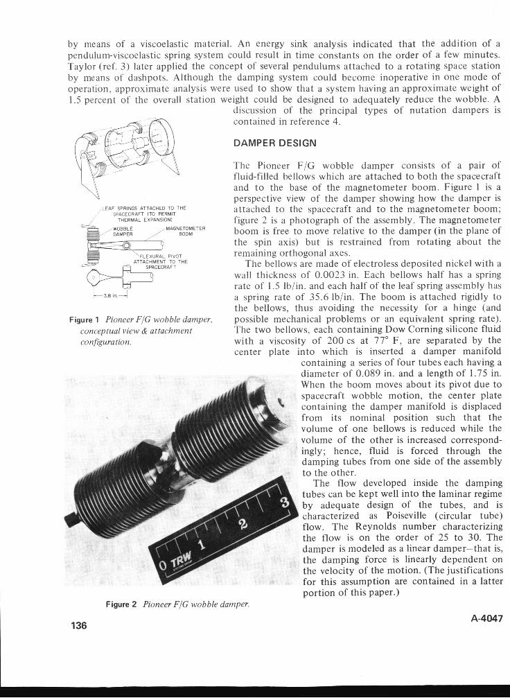
by means of a viscoelastic material. An energy sink analysis indicated that the addition of a pendulum-viscoelastic spring system could result in time constants on the order of a few minutes. Taylor (ref. 3) later applied the concept of several pendulums attached to a rotating space station by means of dashpots. Although the damping system could become inoperative in one mode of operation, approximate analysis were used to show that a system having an approximate weight of 1.5 percent of the overall station weight could be designed to adequately reduce the wobble. A
discussion of the principal types of nutation dampers is contained in reference 4.
DAMPER DESIGN
,LEAF SPRINGS ATTACHED TO THE ' SPACECRAFT (TO PERMIT
THERMAL EXPANSION)
ATTACHMENT TO THE
'- 3.8 in.+
Figure 1 Pioneer FIG wobble damper, conceptual view & attachment configuration.
The Pioneer F/G wobble damper consists of a pair of fluid-filled bellows which are attached to both the spacecraft and t o the base of the magnetometer boom. Figure 1 is a perspective view of the damper showing how the damper is attached t o the spacecraft and t o the magnetometer boom; figure 2 is a photograph of the assembly. The magnetometer boom is free to move relative to the damper (in the plane of the spin axis) but is restrained from rotating about the remaining orthogonal axes.
The bellows are made of electroless deposited nickel with a wall thickness of 0.0023 in. Each bellows half has a spring rate of 1.5 lb/in. and each half of the leaf spring assembly has a spring rate of 35.6 lb/in. The boom is attached rigidly to the bellows, thus avoiding the necessity for a hinge (and possible mechanical problems or an equivalent spring rate). The two bellows, each containing Dow Corning silicone fluid with a viscosity of 200 cs at 77" F, are separated by the center plate into which is inserted a damper manifold
containing a series of four tubes each having a diameter of 0.089 in. and a length of 1.75 in. When the boom moves about its pivot due to spacecraft wobble motion, the center plate containing the damper manifold is displaced from its nominal position such that the volume of one bellows is reduced while the volume of the other is increased correspond- ingly; hence, fluid is forced through the damping tubes from one side of the assembly to the other.
The flow developed inside the damping tubes can be kept well into the laminar regime by adequate design of the tubes, and is characterized as Poiseville (circular tube) flow. The Reynolds number characterizing the flow is on the order of 25 to 30. The damper is modeled as a linear damper-that is, the damping force is linearly dependent on the velocity of the motion. (The justifications for this assumption are contained in a latter portion of this paper.)
136
Figure 2 Pioneer FIG wobble damper.
A-4047
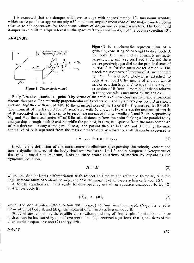
It is expected that the damper will have to cope with approximately 12" maximum wobble, which corresponds to approximately +3" maximum angular excursions of the magnrtnmr ter boom relative to the spacecraft for the chosen values of design and system parameters. The boom and damper have built-in stops internal to the spacecraft t o prevent motion of the boom exceeding 2 3 ' .
ANALYSIS
Figure 3 is a schematic representation of a system S, consisting of two rigid bodies, body A and body B; a , , a,, and a, designate mutually perpendicular unit vectors fixed in A, and these are, respectively, parallel t o the principal axes of inertia of A for the mass center A* of A. The associated moments of inertia of A are denoted by I*, J A , and K A . Body B is attached to uudy A at point 0 by meaiis of a pivot whose axis of rotation is parallel to a, , and any angular excursion of B from its nominal position relative to the spacecraft is measured by the angle @.
Body B is also attached to point 0 by virtue of the actions of a torsional spring u and a torsional viscous damper c. The mutually perpendicular unit vectors, b , , and b3 are fixed in body B as shown and are, together with a ? , parallel to the principal axes of inertia of B for the mass center B* of B. The moment of inertia of B for B* associated with b , and a2 is IB , whereas the moment of inertia of B associated with b3 is taken to be zero. The masses of the two bodies, A and B, are respectively MA and MB ; the mass center B* of B lies at a distance p from the point 0 along a line parallel t o b3 and passing through both 0 and B* while the point 0, in turn, is displaced from the mass center A* of A a distance h along a line parallel to a3 and passing through both A* and 0. Finally, the mass center A* of A is separated from the mass center S* of S by a distance r which can be expressed as
TORSIONAL SPRING. U AND 1.1 TORSIONAL DASHPOT. C r.'i'; S.. ,A* -b3 - 93
1- - ~~ I 1 / 0 2 c- +-I
Figure 3 The analysis model.
Invoking the definition of the mass center to eliminate r, expressing the velocity vectors and inertia dyadics in terms of the body-fixed unit vectors ai, i = 1,3, and subsequent development of the system angular momentum, leads to three scalar equations of motion by expanding the dynamical equation,
H = M (2)
where the dot indicates differentiation with respect to time in the reference frame R, H is the angular momentum of S about S* in R, and M is the moment of all forces acting on S about S*.
A fourth equation can most easily be developed by use of an equation analogous to Eq. (2) written for body B,
Nhere the dot Jznotes differentiation with respect to time in reference R ; (H)B, the mgular r m m n t u r n of body B, and
Study of motions about the equilibrium solution consisting of simple spin about a line colinear u i t h o 1 can be facilitated by one of two methods: (1 ) linearized equations, that is, soluticlw of thz ciuracteristic equations; and (2) energy sink.
the moment of all forces acting U I I body €3.
A-4047 137
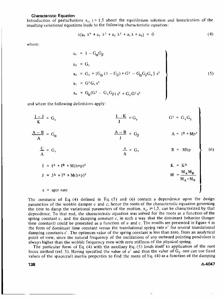
Characteristic Equation Introduction of perturbations xi, i = 1,5 about the equilibrium solution and linearization of the resulting variational equations leads to the following characteristic equation:
h{a, h4 + a3 X 3 + a , h z + a , h +a,) = 0 ( 4)
where:
a, = 1 - G,Gp
a3 = G I
and where the following definitions apply:
Gx I - J =
K
Ga A - B =
A
c = G , A
I = IA + I B + M(h+p),
J = J A + IB + M(h+p),
GY I - K =
J
Go A - B = J
G , L= A
GZ = G,G,
.4 = I B +Mp2
B =-Mhp
K = KA
MA MB M A + M B
M =
s = spin rate
The constants of Eq. (4) defined in Eq. (5 ) and (6) contain a dependence upon the design parameters of the wobble damper u and c; hence the roots of the characteristic equation governing the time to damp the variational parameters of the motion, xi , i=1,5, can be characterized by that dependence. To that end, the characteristic equation was solved for the roots as a function of the spring constant u, and the damping constant c, in such a way that the dominant behavior (longer time constant) could be presented as a function of u and c. The results are presented in figure 4 in the form of dominant time constant versus the translational spring rate u' for several translational damping constants c'. The optimum value of the spring constant is less than zero, from an analytical point of view, since the natural frequency of the oscillations of any outward pointing pendulum is always higher than the wobble frequency even with zero stiffness of the physical spring.
The particular form of Eq. (4) with the auxiliary Eq. ( 5 ) lends itself to application of the root locus method (ref. 5 ) . Having specified the value of u' and thus the value of G2 one can use fixed values of the spacecraft inertia properties to find the roots of Eq. (4) as a function of the damping
138 A-4047
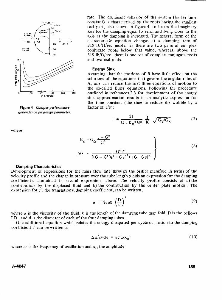
.5 1.0 -- - 2 5 m, s
I I 0 50 103 150 xx) 253
c: Ib/fl/sec
Figure 4 Damper performance dependence on design parameter.
where
rate. The dominant vehavior of the system (longer time constant) is characterized by the mots having the smallest real part, also shown in figure 4, to lie on the imaginary azis for the damping equal to zero, and lying close to the axis as the damping is increased. The general form of the characteristic equation changes at a damping rate of 319 lb/ft/sec insofar as there are two pairs of complex conjugate roots below that value, whereas, above the 319 lb/ft/sec, there is one set of complex conjugate roots and two real roots.
Energy Sink Assuming that the motions of B have little effect on the solutions of the equations that govern the angular rates of A, one can reduce the first three equations of motion to the so-called Euler equations. Following the procedure outlined in references 2,3 for development of the energy sink approximation results in an analytic expression for the time constant (the time factor of l/e):
21 G c KoZMZ
7 =
Ko=G,- 1 -G2 G2
to reduce the wobble by a
( 7 )
MZ = G4 s4 [ (G - GZ )sz + G2 12+ [GI G SI
Damping Characteristics Development of expressions for the mass flow rate through the orifice manifold in terms of the velocity profile and the change in pressure over the tube length yields an expression for the damping coefficient c contained in several expressions above. The velocity profile consists of a) the contribution by the displaced fluid and b) the contribution by the center plate motion. The expression for c’, the translational damping coefficient, can be written,
c’ = 277PQ (+) 2
(9)
where p is the viscosity of the fluid, Q is the length of the damping tube manifold, D is the bellows I.D., and d is the d.iameter of each of the four damping tubes.
One additional equation which relates the energy dissipated per cycle of motion t o the damping coefficient c‘ can be written as
AE/cycle = nc’dxo2 (10)
where w is the frequency of oscillation and xo the amplitude.
A-4047 139
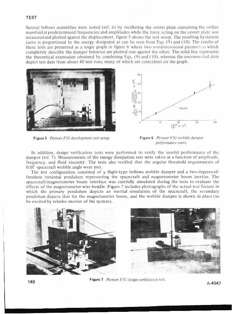
TEST
Several bellows assemblies were tested (ref. 6 ) by oscillating the center plate containing the orifice manifold at predetermined frequencies and amplitudes while the force acting on the center plate was measured and plotted against the displacement, figure 5 shows the test setup. The resulting hysteresis curve is proportional to the energy dissipated as can be seen from Eqs. (9) and (10). The results of these tests are presented as a single graph in figure 6 where two nondimensional paramekis which completely describe the damper behavior are plotted one against the other. The solid line represents the theoretical expression obtained by combining Eqs. (9) and ( I O ) , whereas the unconnected dots depict test data from about 40 test runs, many of which are coincident on the graph.
Figure 5 Pioneer FIG development test setup.
0 10 20 30 40 (5y ( x 10')
Figure 6 Pioneer FIG wobble damper performance curve.
In addition, design verification tests were performed to verify the inorbit performance of the damper (ref. 7). Measurements of the energy dissipation rate were taken as a function of amplitude, frequency, and fluid viscosity. The tests also verified that the angular threshold requirements of 0.01" spacecraft wobble angle were met.
The test configuration consisted of a flight-type bellows wobble damper and a two-degrees-of- freedom torsional pendulum representing the spacecraft and magnetometer boom inertias. The spacecraft/magnetometer boom interface was carefully simulated during the tests to evaluate the effects of the magnetometer wire bundle. Figure 7 includes photographs of the actual test fixture in which the primary pendulum depicts an inertial simulation of the spacecraft, the secondary pendulum depicts that for the magnetometer boom, and the wobble damper is shown in place (to be excited by relative motion of the system).
r
140 Figure 7 Pioneer FIG design verification t a t . A-4047
CONCLUSIONS The design, analysis, and test of a passive pendulum wobble damper have been briefly presented. The damper has been shown to follow the theoretical behavior very closely, and to perform in such a way that the spacecraft wobble motion is damped to small values within few wobble cycles. Additional testing, not covered in this paper, has shown that the damper is able to survive the launch environment with a larger margin for success.
REFERENCES
1.
2.
3.
4.
5.
6.
7.
Taylor, R. S.; and Conway, J . J.: Viscous Ring Precession Damper for Dual-Spin Spacecraft. Proc. Symposium on Attitude Stabilization and Control of Dual-Spin Spacecraft, 1-2 August 1967. Alper, J . R.: Analysis of Pendulum Damper for Satellite Wobble Damping. J . Spacecraft 2,
Taylor, R. S.: A Passive Pendulum Wobble Damping System for a Manned Rotating Space Station. J . Spacecraft 3, i 966, pp. i 22 i - i 228. Feder, J. V.; Tossman, B. E.; Spencer, T. M.; Durghals, P. R.; and Herzl, G. G.: Panel Discussion on Nutation Dampers. Proc. 5th Aerospace Mechanism Symposium, NASA Space Flight Center, June 15- 16, 197 1, To Be Published by NASA. McElroy, T. T.: Analysis of the Effect of the Magnetometer Boom on the Precession and Wobble Motion of Pioneer F/G. TRW IOC 70.7231.9-35, 25 March 1970. Fowler, R. C.: Development Test Report, Wobble Damper-Pioneer F/G. TRW
Fowler, R. C.: Design verification Test Report - Pioneer F/G Wobble Damper. TRW IOC 70-4343.3-207, 1 Dec 1970.
1965, pp. 50-54.
IOC 70-4343.3-165, 22 Sept. 1970.
ACKNOWLEDGEMENT
Work performed under Contract NAS2-5600.
A-4047 141
DOCKlP?G DEV!CES FOR SOYUZ-TYPE SPACECRAFT
V. S. Syromyatnikov USSR
ABSTRACT. Two docking-device designs for Soyuz-type spacecraft are compared. The first was flight tested successfully; the second achieves rigid and exact joining of two spacecraft while also incorporating changes t o allow for the intravehicular transfer of crewmen. The main functions of the docking device are considered with the means by which they are accomplished, and measures for increasing its reliability and flexibility in service are noted.
INTRODUCTION
A device has been constructed to achieve the direct and rigid joining of two Soyuz spacecraft by electric coupling. Design of this device introduced a number of new, basic problems requiring solution. These included kinematic and dynamics problems, questions of interaction, control, and selection of materials, and technological and testing requirements.
The docking device was designed on the matching-of-cones, or “probe-drogue,” principle, which permits achicvcment of al! the miin f~mctinns and requirements of spacecraft docking, compensating for the errors inherent in the rendezvous operation so that proper joining is accomplished.
In its original design, the docking device demonstrated rigid and exact joining of the two spacecraft. From experience gained with this first device and the engineering solutions obtained in designing the separate units for joining two spacecraft, a second docking device was designed and constructed that also provided for intravehicular transfer of crewmen through a pressure-tight tunnel assembly. In this paper, the docking structure is discussed and the various elements of the two designs are compared.
STRUCTURE AND OPERATION OF THE BASIC DOCKING DEVICE
The docking device consists of two functionally and physically autonomous assemblies, one on each of the spacecraft to be joined. The active docking assembly comprises a docking ring and the docking mechanism; the passive docking assembly comprises a docking ring and drogue, which receives probe head of the docking mechanism. The docking mechanism fulfills the basic functions of joining the two spacecraft until the docking rings come into contact - that is, pulling the spacecraft together, alinement, coupling, and shock attenuation. The docking ring of the active assembly is a primary structure that houses other assembly elements, including the docking mechanism, peripheral set pins, electrical connectors, and transducers. For the docking device providing intravehicular access, the docking ring also contains a tunnel hatch, peripheral latches. a joint seal, and other elements.
Figure 1 is a general view of the docking mechanism that was successfully flight tested on board the Soyuz spacecraft. The docking mechanism consists of a small screw with a head, a ball-screw
A-4047 143
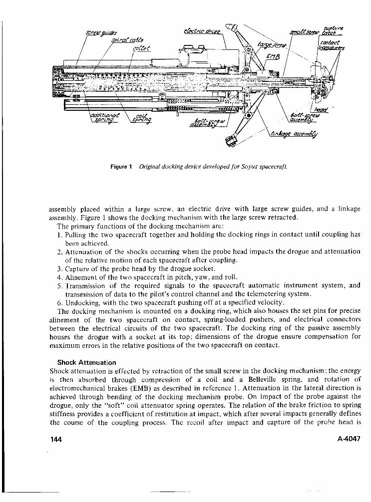
Figure 1 Original docking device developed for Soyuz spacecraft.
assembly placed within a large screw, an electric drive with large screw guides, and a linkage assembly. Figure 1 shows the docking mechanism with the large screw retracted.
The primary functions of the docking mechanism are: 1 . Pulling the two spacecraft together and holding the docking rings in contact until coupling has
been achieved. 2. Attenuation of the shocks occurring when the probe head impacts the drogue and attenuation
of the relative motion of each spacecraft after coupling. 3. Capture of the probe head by the drogue socket. 4. Alinement of the two spacecraft in pitch, yaw, and roll. 5. Transmission of the required signals to the spacecraft automatic instrument system, and
6. Undocking, with the two spacecraft pushing off at a specified velocity. The docking mechanism is mounted on a docking ring, which also houses the set pins for precise
alinement of the two spacecraft on contact, spring-loaded pushers, and electrical connectors between the electrical circuits of the two spacecraft. The docking ring of the passive assembly houses the drogue with a socket at its top; dimensions of the drogue ensure compensation for maximum errors in the relative positions of the two spacecraft on contact.
transmission of data to the pilot’s control channel and the telemetering system.
Shock Attenuation Shock attenuation is effected by retraction of the small screw in the docking mechanism; the energy is then absorbed through compression of a coil and a Belleville spring, and rotation of electromechanical brakes (EMB) as described in reference 1 . Attenuation in the lateral direction is achieved through bending of the docking mechanism probe. On impact of the probe against the drogue, only the “soft” coil attenuator spring operates. The relation of the brake friction to spring stiffness provides a coefficient of restitution at impact, which after several impacts generally defines the course of the coupling process. The recoil after impact and capture of the prohe head is
144 A-4047
absorbed by pulling back the small screw and compressing the Belleville spring and an additional spring in the screw tail.
Capture The probe head is captured by the drogue socket by two latches on the head, which enter appropriate socket slots.
Spacecraft AI inement As the spacecrafts are pulled together, their alinement is accomplished by an electric drive, which retracts the large screw. Pitch and yaw alinement is controlled by the linkage assembly, while roll alinement is achieved by pulling up the latches inside narrowing socket slots. To reduce friction during alinement, the arms are fitted with rollers. Once the docking rings have made contact, the force required for capture is produced by the safety clutch of the drive and maintained by a locking clutch.
I he necessary precision or tile relative posiiioiis of the two spacecraft about thc !ongit.;dinal axis is achieved by the peripheral set pins and the mate sockets, which when positioned with the requisite accuracy, aline the two spacecraft in the last moments before capture.
-.
Instrumentation The docking device is equipped with a set of transducers that monitor the docking maneuver through signals transmitted to adjacent systems, the pilot’s control panel, and the telemetering system. These include contact and “catch-up” transducers located in the probe head, end ‘and intermediate contacts of the drive, and interface contacts. Electrical signals are transmitted from moving parts of the docking mechanism (the small and large screws) to the drive body by means of a two-sectioned spiral cable.
Undocking Undocking of the two spacecraft can be accomplished by either the active or the passive assembly, or by pyrotechnic means. In the case of the passive assembly, undocking is achieved merely by jettisoning the socket stops. If undocking is to be accomplished with the active assembly, the large screw is extended into the extreme forward position, the attenuator springs are compressed, a collet holding the small screw is unlocked, the headlatches are unlocked, and the two spacecraft push off, driven apart by energy released by the expanding attenuator springs.
STRUCTURE AND OPERATION OF THE DOCKING DEVICE FOR INTRAVEHICULAR TRANSFER
In this design, a pressure-tight intravehicular tunnel assembly was provided t o allow transfer of crewmen between the two spacecraft after docking.
Basic Design Principles The docking device providing for intravehicular transfer was designed according t o the following basic principles:
1. The assemblies were developed, manufactured, and tested, from the standpoint of both technological and physical requirements, as autonomous units, completely separate from the spacecraft.
2. The active and passive assemblies were designed as similar, interchangeable structures so that if necessary, it would be possible with appropriate modifications t o dock two active or two passive assemblies.
A-4047 145
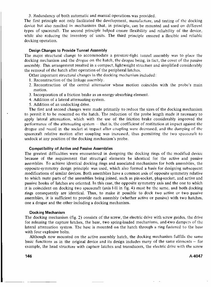
3. Redundancy of both automatic and manual operations was provided. The first principle not only facilitated the development, manufacture, and testing of the docking device but also resulted in mechanisms that, in principle, can be mounted and used on different types of spacecraft. The second principle helped ensure flexibility and reliability of the device, while also reducing the inventory of units. The third principle ensured a flexible and reliable docking operation.
Design Changes to Provide Tunnel Assembly The major structural change t o accommodate a pressure-tight tunnel assembly was to place the docking mechanism and the drogue on the hatch, the drogue being, in fact, the cover of the passive assembly. This arrangement resulted in a compact, lightweight structure and simplified considerably the removal of the hatch after operation of the peripheral latches.
Other important structural changes in the docking mechanism included: 1. Reconstruction of the linkage assembly. 2. Reconstruction of the central attenuator whose motion coincides with the probe’s main
3. Incorporation of a friction brake as an energy-absorbing element. 4. Addition of a lateral attenuating system. 5. Addition of an undocking drive. The first and second changes were made primarily t o reduce the sizes of the docking mechanism
to permit it to be mounted on the hatch. The reduction of the probe length made it necessary to apply lateral attenuation, which with the use of the friction brake considerably improved the performance of the attenuating system - that is, the coefficient of restitution at impact against the drogue and recoil in the socket at impact after coupling were decreased, and the damping of the spacecraft relative motion after coupling was increased, thus permitting the two spacecraft to undock at any position of the docking mechanism’s probe.
motion.
Compatibility of Active and Passive Assemblies The greatest difficulties were encountered in designing the docking rings of the modified device because of the requirement that structyal elements be identical for the active and passive assemblies. To achieve identical docking rings and associated mechanisms for both assemblies, the opposite-symmetry design principle was used, which also formed a basis for designing subsequent modifications of similar devices. Both assemblies have a common axis of opposite symmetry relative to which mate parts of the assemblies being joined, such as pin-socket, plug-socket, and active and passive hooks of latches are oriented. In this case, the opposite symmetry axis and the one to which it is coincident on docking two spacecraft (axis 1-11 in fig. 4) must be the same, and both docking rings consequently are identical. Thus, to make it possible to dock two active or two passive assemblies, it is sufficient t o provide each assembly (whether active or passive) with two hatches, one a drogue and the other including a docking mechanism.
Docking Mechanism The docking mechanism (fig. 2) consists o f t h e screw, the electric drive with screw guides, the drive for releasing the capture latches, the base, two spring-loaded mechanisms, and .two dampers of the lateral attenuation system. The base is mounted on the hatch through a ring fastened t o the base with four explosive bolts.
Although now mounted on the active assembly hatch, the docking mechanism fulfills the same basic functions as in the original device and its design includes many of the same elements - for example, the head structure with capture latches and transducers, the electric drive with the screw
146 A-4047

\
I \ I . -
Figure 2 Revised docking device developed to provide for intravehicular transfer of crewmen - “probe-drogue ”mechanisms in retracted and stored configuration.
and ball-screw assembly, the linkage assembly for alinement in pitch and yaw, and alinement in roll by means of narrowing socket slots.
The mechanism for opening and pressurizing the hatch is mounted on the spacecraft side of the docking ring (figs. 3 and 4); the peripheral latches, their drive, the set pin and its socket (parts of hydraulic connectors), plugs and sockets of electrical connectors, spring-loaded pushers, and transducers are located inside the docking ring. All the elements and their mate parts are located symmetrically about axis 1-111. The docking seal consists of two concentric rubber rings located on the active assembly. To provide identical means of sealing for both the active and passive assemblies, however, presents no great problems.
Shock Attenuation Impact attenuation is effected by retraction of the probe and swinging the drive with the screw about the base in a ball-and-socket joint. On retraction of the screw, the central attenuator first works “softly” (at impacts against the drogue), the spiral spring being twisted and electromechanical brakes rotating; then at a certain stroke (after the probe head enters the socket), the friction self-regulating brake begins to slip, providing a stable value of attenuating force in this phase and dissipation of a great part of the impact energy.
A-4047 147
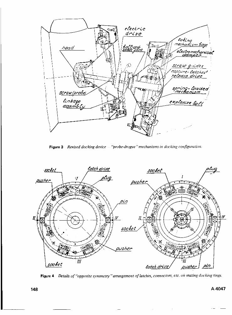
Figure 3 Revised docking device - “probe-drogue ”mechanisms in docking configuration.
148
Figure 4 Details of “opposite symmetry”arrangement of latches, connectors, etc. on mating docking rings.
A-4047

On attenuation in the iaterai direction, the impsct eiiergy is absorbed (dissipzted) by the electromechanical brakes and spring-loaded mechanisms that return the system to its original position after impact.
When the probe head has been caught by the drogue socket and relative spacecraft motions have been attenuated, the docking mechanism’s drive is actuated to pull and aline the spacecraft. The alinement is accomplished by the narrowing socket slots and through expanding the lilikage assembly by a cam rotating synchronously with the screw movement.
The drive keeps the spacecraft pulled together with an uncontrolled locking clutch.
System of Peripheral Latches The system of peripheral latches was designed to make a shackling force exceeding all external and internal tension that can affect the interface during a joint flight of the spacecraft. The internal pressure produces most of the total force; this load for the structure considered is equal to 8 tons at
Each of the eight peripheral latches (view A, fig. 4) consists of an active hook being moved by an eccentric mechanism and a passive spring-loaded hook. All pulleys of eccentric shafts and a drum of the latches’ drive are connected by an endless rope that makes possible their rotation in both directions. The active (movable) and passive hooks are positioned on each assembly relative to the opposite symmetry axis in such a way that on docking the active hooks gear the passive ones of an active or passive assembly of another spacecraft. The active latches are actuated by the electric drive through a ciosed fiexibie tie. To compensate for !a:ch-positim errcrs due to tnlerrrnces and irregularity of strokes, the passive hooks are provided with preloaded springs, which provide a required force of the interface precompression.
While the docking mechanism is pulling the two spacecraft together, the active hooks are in an open (not coupled with the passive ones) position in which they are kept by the eccentric shaft pin. At the beginning of rotation the pins move back, and the active hooks engage the passive ones by the action of the spring. On subsequent rotation the hooks are shackled.
To increase the number of shackling points and thus improve the interface pressurization conditions, the structure is designed such that the force of each latch is distributed into two points, with all shackling points being uniformly distributed in the interface circumference. Due to the presence of independent active latches on each assembly the reliability of the docking device is increased in terms of mechanism redundancy as well as the capacity for a double shackling force.
! kg/sq cm.
Hatch Mechanisms The mechanisms for opening and pressurizing the hatch include a set of battening-down elements connected by rods and actuated by the electric drive, and the hatch-opening drive swinging the lever. An additional swinging axis between the lever and the hatch facilitates its exact fixation on closing and provides an additional clearing of the intravehicular transfer tunnel upon its opening.
Undocking Once the hatches are closed, undocking of the spacecraft is accomplished by turning the eccentric shafts in the opposite direction through using the drive, the pins simultaneously disengaging all the active and passive hooks. The spacecrafts are then pushed apart with four spring-loaded pushers (two pushers on each assembly).
Undocking is backed up by pyrotechnics. On blasting the explosive bolts, two parts of the active hook turn about and the hooks disengage.
A-4047 149

Instrumentation and Manual Operations Automatic instruments mounted on the docking assemblies control all the mechanisms and monitor the performance of all the docking and undocking operations both automatically and from the pilot control panel. To provide automatic control and transmit data to the pilot panel and the telemetering system, all the assembly mechanisms are fitted with a set of transducers that monitor systems performance.
Control of the passive assembly’s mechanisms by the active assembly is provided, as is the reception of reverse data into the automatic instrument and the active spacecraft’s pilot panel. In addition, separate operation commands can be transmitted t o both the active and passive assemblies over a radio-command link.
A number of operations can be performed manually, thus increasing the potential applications and overall reliability of the device.
The drives of the hatch opening and pressurizing mechanism are fitted with an electromagnetic clutch, which when it is de-energized mechanically cuts off the drive. To permit the pressurization and depressurization of the passive assembly hatch by the active assembly mechanism, a transmission is provided outside the assembly at the point on the body that is accessible after opening the active assembly hatch.
CONCLUSION
The docking device described here is a complex, multifunctional system. The basic design and its modifications demonstrate ways of solving the problems of both docking the spacecraft and of designing other space mechanisms.
REFERENCE
1 . Syromyatnikov, V. S . : Docking Mechanism Attenuation With Electromechanical Damper. Proceedings of the 5 th Aerospace Mechanisms Symposium, June 1970, NASA-Goddard Spaceflight Center.
150 A-4047

LIST OF ATTENDEES
CLARK, THOMAS S. United Technology Corp.
CONNER, GARY E. United Technology Corp.
COOPER, STANLEY Johns Hopkins University
CRAIGHEAD, N. D. Lockheed Missiles & Space Co.
CUNNINGHAM, BERNARD NASA-Ames Research Center
CUNNINGHAM, D. Sperry Flight Systems Division
DAHLGREN, JOHN B. Jet Prnpulsion Laboratory
DALLAM, W. F., JR. Air Force Systems Command Hamilton AFB
DAMASSA, P. L. Lockheed Missiles & Space Co.
DAVIS, C. Teledyne-Ryan Aeronautical
DICKINSON, JACK NASA-Ames Research Center
DiSANTO, FRANK S. General Electric Co.
EASTMAN, DOUGLAS Lockheed Missiles & Space Co.
ELLIOTT, HARRY R. AFPRO/Lockheed
ELMORE, JOHN T. Lockheed Missiles & Space Co.
ENGELBERT, DAVID F. NASA-Ames Research Center
EUGENE, K. T. Lockheed Missiles & Space Co.
FELLER, A. C. Lockheed Missiles &Space Co.
FERRARA, JOHN Jet Propulsion Laboratory
FISHER, EUGENE University of Santa Clara
FOWLER, RANDALL TRW Systems Group
FRENCH, K. E. Lockheed Missiles & Space Co.
GAEFCKE, ROGER L. Hughes Aircraft Co.
ACKER, ROY M. TRW Systems Group
ADAMS, JAMES Stanford University
ANDERSON, DONALD L. NASA-Ames Research Center
ARMSTRONG, H. H. Lockheed Missiles & Space Co.
BAKKE, ALLAN P. NASA-Ames Research Center
BENNETT, JOHN E. Aerospace Corp.
BIETZ, R. J. Lockheed Missiles & Space Cc.
BINGEMANN, C. Hughes Aircraft Co.
BINZ, ERNEST F. North American Rockwell Corp.
BOEHME, MARTIN L. Sylvania
EOMF., PAUL Jet Propulsion Laboratory
BRANDON, LT. COL. DURWARD AFPRO/Lockheed
BRIGHT, LOREN NASA-Ames Research Center
BROADBENT, SIDNEY Martin-Marietta Corp.
BRODERICK, JOHN J. NASA- Ames Research Center
BROWN, JERRY C. Lockheed Missiles & Space Co.
BROWN, TED M. NASA-Ames Research Center
BUERGER, E. J. General Electric Co.
BUNSON, G. A. Santa Barbara Research Center
CAMPBELL, ALAN NASA-Ames Research Center
CAMPBELL, G. K. Lockheed Missiles & Space Co.
CAREN, CHRIS Lockheed Missiles & Space Co.
CAVEY, E. F. Lockheed Missiles & Space Co.
CHRISTIANSEN, ROBERT A. NASA-Ames Research Center
A-4047
GALBRAITH, A. D. Lockheed Missiles & Space Co.
GARDNER, NORMAN E. Lockheed Missiles & Space Co.
GAYMAN, MERLIN W. Jet Propulsion Laboratory
GIOVANNETTI, A. NASA-Ames Research Center
GLASSOW, F. A. Hughes Aircraft Co.
GOODWIN, GLEN G. NASA-Ames Research Center
GRAM, MARSHALL G. Jet Propulsion Laboratory
GRAVELINE, R. P. Lockheed Missiles & Space Co.
GROSKOPFS, E. Spar Aerospace Products, Ltd.
HADAS, V. Stanford University
HANGARTNER, JIMMIE G. NASA-Kennedy Space Center
HAYNIE, THERON Boeing Co.
HECKMANN, RUDOLF A. United Technology Corp.
HEDGEPETH, K. NASA-Langley Research Center
HERMACH, CHARLES NASA-Ames Research Center
HESPRICH, G. V. TRW Systems Group
HERZL, GEORGE Lockheed Missiles & Space Co.
HIRATA, JERRY H. NASA-Ames Research Center
HITCHCOCK, JERRY Sylvania
HODDLE, R. H. Lockheed Missiles & Space Co.
HOLLISTER, MYRON P. Lockheed Missiles & Space Co.
HOLMES, ROBERT E. NASA-Ames Research Center
HOWEY, C. K. Aerospace Corp.
HUANG, PROF. FRANCIS San Jose State College
151

LIST OF ATTENDEES (Contd)
HURD, W. L., JR.
JENKINS, LARRY
JONES, CALVIN L.
Lockheed Missiles & Space Co.
Lockheed Missiles & Space Co.
U.S. Dept. of Comm. NOAA NESS
JONES, JAMES C. NASA-Manned Spacecraft Center
JONES, JOHN R. Hughes Aircraft Corp.
JONES, KEN Lockheed Missiles & Space Co.
JONES, R. W. Hughes Aircraft Corp.
KELLAR, WALTER University of Santa Clara
KELLER, L. BRIAN Hughes Aircraft Corp.
KIEVIT, JOHN C. Jet Propulsion Laboratory
KIMBALL, J. B. Lockheed Missiles & Space Co.
KIRKPATRICK, DONALD General Electric Co.
KODA, RICHARD Lockheed Missiles & Space Co.
KODAK, J. C. Santa Barbara Research Center
KOWALEWSKI, MAJ. STEPHEN AFPRO/Lockheed
KRAKOV, EDWIN United Technology Corp.
KRAPP, R. B. Lockheed Missiles & Space Co.
KUHN, J. G. Santa Barbara Research Center
LATAPIE, FRANCIS French Scientific Mission
LAWRENCE, H. J. Lockheed Missiles & Space Co.
LEWIN, JOSEPH Stanford University
LINDGREN, MATTS J. Lockheed Missiles & Space Co.
LINIECKI, PROF. A. San Jose State College
LOMAS, W. E. Lockheed Missiles & Space Co.
LOUDON, JACK Ball Brothers Research Corp.
152
LOVELL, ROBERT B. Level1 Enterprise
LUDLOW, KENNETH Aerospace Corp.
MacLEAN, C. F. Lockheed Missiles & Space Co.
MACUMBER, DONALD Martin-Marietta Corp.
MAGERS, ROBERT NASA-Ames Research Center
MAJORS, HARRY Seattle University
MANOOGIAN, HAROLD Hughes Aircraft Co.
MARCUS, J. P. Martin-Marietta Corp.
MARTIN, FRANK NASA-Goddard Space Flight Center
MATTHEWS, H. NASA-Ames Research Center
McCARTHY, D. NASA-Goddard Space Flight Center
MENEELY, ROBERT W. NASA-Ames Research Center
MENEFEE, EARL 0. NASA-Ames Research Center
MENNING, M. D. Lockheed Missiles & Space Co.
MIKSCH, R. S. Lockheed Missiles & Space Co.
MOBLEY, ROBERT NASA-Ames Research Center
MOISEFF, ANNE Lockheed Missiles & Space Co.
MORTENSEN, WILLIAM E. Electro-Optical Systems Division of Xerox
MULLER, TIM University of Santa Clara
MURACA, ROBERT NASA-Langley Research Center
MURPHY, JAMES B. Air Supply Co.
NASH, J., DR. Lockheed Missiles & Space Co.
NEITZEL, F. J. Santa Barbara Research Center
NEM EC EK, JOSEPH Naval Research Laboratory
NILSON, REX A. United Technology Corp.
OHAGAN, M. A. Lockheed Missiles & Space Co.
OLLENDORF, S. NASA-Goddard Space Flight Center
ONG, HARRY T. Sylvania
PARKS, JAMES NASA-Langley Research Center
PEFLEY, R. University of Santa Clara
PETERSON, ROD General Dynamics
PETTIT, E. M. McDonnell Douglas
PISTOLE, GORDON S. Philco-Ford
POLASKI, LOUIS NASA-Ames Research Center
PRATER, C. R. Lockheed Missiles & Space Co.
REED, W. B. Lockheed Missiles & Space Co.
REPANICH, SIMON J. AFPRO/Lockheed
RIEDEL, JOHN Lockheed Missiles & Space Co.
RINALDO, A. Lockheed Missiles & Space Co.
RIZZO, TONY TRW Systems Group
ROBBINS, L. B. Lockheed Missiles & Space Co.
ROSKELLEY, D. W. Lockheed Missiles & Space Co.
RUSSELL, MAX D. AVCO Corp.
RYAN, R. J. Lockheed Missiles & Space Co.
SALAT, S. Lockheed Missiles & Space Co.
SECHLER, E. E. Calif. Institute of Technology
SECOLA, A. V. Lockheed Missiles & Space Co.
SEIFERT, HOWARD S. Stanford & Jet Propulsion Laboratory
SELENE, L. J. Phlco-Ford
SHARFSTEIN, PROF. H. San Jose State College
A-4047
LIST OF ATTENDEES (Concld) L
SIMMONS, DELFORD E. Design Engr. Sect.
SMALLEN, HAROLD Aerospace Corp.
SMITH, D. D. Lockheed Missiles & Space Co.
SPANGLER, L. L. TRW Systems Group
STIPANDIC, E. NASA -Goddard Space Flight Center
STRATOS, P. G. Lockheed Missiles & Space Co.
STOTZKY, GEORGE A . Lockheed Missiles & Space Co.
TENDELAND, THORVAL NASA-Ames Research Center
TESKE, J . H. Lockheed Missiles & Space Co.
THOMPSON, E. D. Martin-Marietta Corp.
A-4047 - 1 5
THOMPSON, ROBERT J. Lockheed Missiles & Space Co.
TOTAH, N. I . Philco-Ford
TYRELL, E. M. General Electric Co.
VALLOTTON, WILBUR C. NASA-Ames Research Center
WALLACE, R. H. Lockheed Missiles & Space Co.
WARD, BETHEL
WARD. BOWDON, JR.
WARD, MARY
WEDLAKE, JERRY
WEILBACH, J.
NASA-Goddard Space Flight Center
NASA-Goddard Space Flight Center
Ball Brothers Research Corp.
Beckman Instruments, Inc.
WEISSENBERGER, S.
WEYMAN, H. N.
WENDT, A.
University of Santa Clara
Spar Aerospace Products, Ltd.
WHELLER, BRYCE A.
WILKES,
WILLIAMS, JAMES P.
WILSON, DOUGLAS D.
YOUNG, BRAD
ZABOWER, HARRY R.
Hughes Aircraft Co.
RCA Corp.
Lockheed Missiles & Space Co.
Lockheed Missiles & Space Co.
Lockheed Mi ssiles & Space Co.
NASA-Ames Research Center
153
*US. GOVERNMENT PRINTING OFFICE: 1972 735-028/1057 1-3