ARCHITECTURAL Working DRAWING /Information handout
18
by Yoseph.F (Architectural Drafter)
Transcript of ARCHITECTURAL Working DRAWING /Information handout
f01
by Yoseph.F
(Architectural Drafter)

ARCHITECTURAL Working DRAWING /Information handout/
Yoseph Fiseha |
ARCHITECTURAL Working DRAWING
Basically Architectural drawings categorized into two broad divisions.
1. PRESENTATION DRAWING
Communicate the form of the building in terms of shape, color and texture.
Such drawing presented to: -
a. Planning regulation offices for design approval.
b. The client
-To help him in understanding of the program.
- To show to him the relationship of spaces and the general concept of the design.
- To illustrate to him the general appearance of the building. (The accommodation
provided. The effect of the overall scheme on the environmental)
- To get approval from him
c. The public
-Produced for use in periodicals, magazines and other publications.
d. Jury members in the evaluation of design competition award.
PRESENTATION DRAWINGS ARE ALSO CLASSIFIED IN TO TWO:
I. Schematic presentation drawing and
II. Design presentation drawing
SCHEMATIC DRAWINGS: -
- Concerned with the preliminary investigation process for a design. Provides, information about:
the site, immediate surrounding (adjoining structures, roads, services etc…)
- Development the entire site, like circulation pattern.
- Rough idea of the functional
DESIGNE DRAWING
- Those concerned with the presentation of design solutions.
- Provide information about:
. Basic room arrangement
. Exterior features
. Immediate surrounding etc …
2. WORKING DRAWING
-Such drawings more need to convey information about appearance because they presented for less
technically minded people. So the presentation should be easily understood and preferably three
dimensional representation (like-perspective), etc
Function provided by working drawing
1. Communicate technical information though out the building team
ARCHITECTURAL Working DRAWING /Information handout/
Yoseph Fiseha |
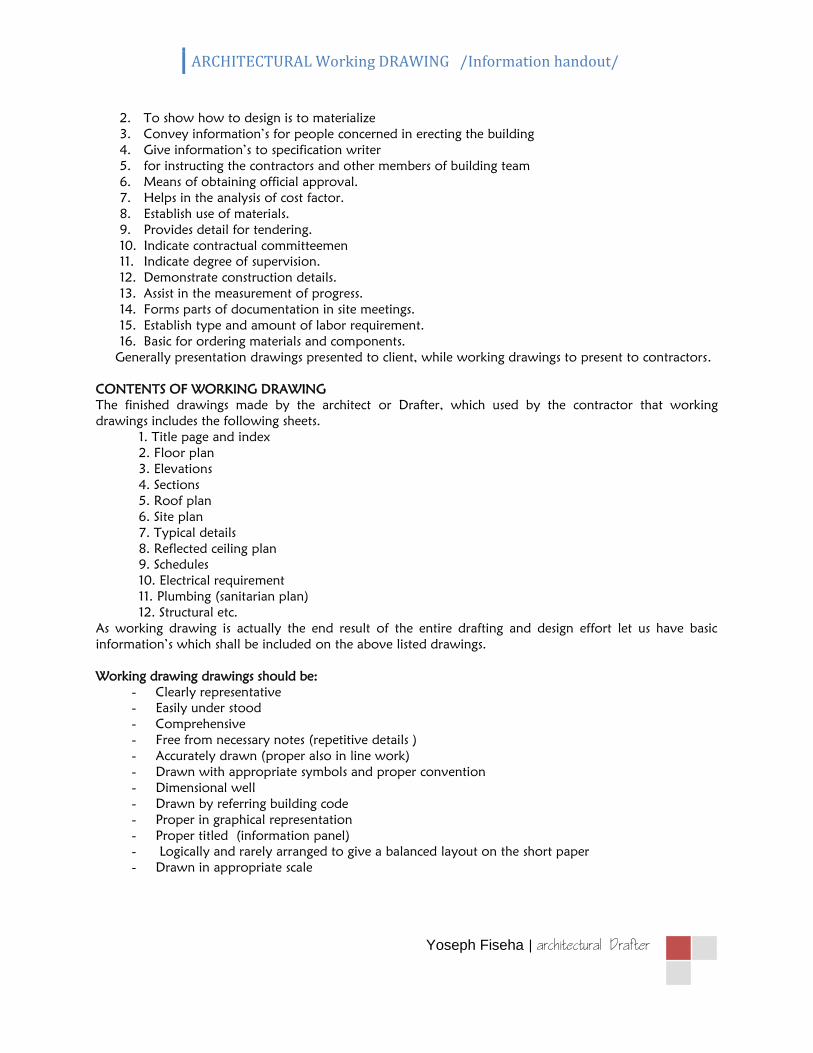
2. To show how to design is to materialize
3. Convey information’s for people concerned in erecting the building
4. Give information’s to specification writer
5. for instructing the contractors and other members of building team
6. Means of obtaining official approval.
7. Helps in the analysis of cost factor.
8. Establish use of materials.
9. Provides detail for tendering.
10. Indicate contractual committeemen
11. Indicate degree of supervision.
12. Demonstrate construction details.
13. Assist in the measurement of progress.
14. Forms parts of documentation in site meetings.
15. Establish type and amount of labor requirement.
16. Basic for ordering materials and components.
Generally presentation drawings presented to client, while working drawings to present to contractors.
CONTENTS OF WORKING DRAWING
The finished drawings made by the architect or Drafter, which used by the contractor that working
drawings includes the following sheets.
1. Title page and index
2. Floor plan
3. Elevations
4. Sections
5. Roof plan
6. Site plan
7. Typical details
8. Reflected ceiling plan
9. Schedules
10. Electrical requirement
11. Plumbing (sanitarian plan)
12. Structural etc.
As working drawing is actually the end result of the entire drafting and design effort let us have basic
information’s which shall be included on the above listed drawings.
Working drawing drawings should be:
- Clearly representative
- Easily under stood
- Comprehensive
- Free from necessary notes (repetitive details )
- Accurately drawn (proper also in line work)
- Drawn with appropriate symbols and proper convention
- Dimensional well
- Drawn by referring building code
- Proper in graphical representation
- Proper titled (information panel)
- Logically and rarely arranged to give a balanced layout on the short paper
- Drawn in appropriate scale

ARCHITECTURAL Working DRAWING /Information handout/
Yoseph Fiseha |
1. FLOOR PLAN
The floor plan is the heart of architectural drawings and is usually drawn first in professional plans. It is the
plan to which all trades people refer. It is a top view horizontal section cut through the house about 1.00 –
1.50cm above the floor. The purpose of the floor plan is to show the location and dimensions of exterior
and interior walls, windows, doors, major appliances, cabinets, fireplaces, and other fixed features in the
house.
Upon completion of the preliminary sketches and proposal, a 1:50 – 1:100 scale floor plan is drawn which
is considerably more detailed than previous floor plans. Windows and doors are coded. All exterior walls,
interior walls, windows, and doors are dimensioned. To conserve time and paper, the electrical plan is
sometimes included on the floor plan. On more complex plans, the electrical plan, the heating/cooling
plan, and the plumbing plan are drawn separately.
You will have one drawing for the floor plan, and one for the electrical.
A. Certain information is required on the floor plan:
Exterior and interior walls
Size and location of windows and doors
Permanent fixtures, stairs, and fireplaces
Sidewalks, patios and decks
Room names and material symbols
Location and size dimensions
Scale of the drawing
B. When applicable, related structures such as freestanding garages or swimming pools
are shown on the floor plan
C. Walls should be drawn accurately. Exterior walls can be either 15cm or 20cm thick,
and interior walls should be 15cm thick. If you are using a brick veneer on the exterior
of the house, add 1” air space and an additional 3‐3/4” for the brick.
D. Fireplaces or stairs require only basic size and location information on the floor plan.
(Special details will be included in the plans for these features.).
E. Floor plans should include several dimensions. Each wall is dimensioned from its
center architectural dimensions should be in chain fashion or continuous and tics should be
used


2. FOUNDATION PLAN
After finishing the floor plan, the same scale foundation plan is drawn. All students will draw a basement
foundation. The weight of a house is supported by footings extended into the ground. These footings are
concrete with steel reinforcing to reduce cracking. The footings must extend below the frost line. All this
information should be given in the foundation plan
A. The foundation plan is a plan view in sections, which shows the location and size of footings,
piers, columns, foundation walls, and supporting beams. It is usually drawn after the floor plan
and elevations have been roughed out.
B. A foundation plan contains: Footings (hidden lines) Foundation walls Piers and columns Dwarf
walls (low walls to retain excavation or an embankment) Partition walls, doors, and bath fixtures
(if the house has a basement) Openings in the foundation walls (doors, windows, and vents)
Beams and pilasters Direction, size, spacing of floor joists, drains, and sump (if required) Details of
the foundation and footing construction. Complete dimensions and notes scale of the drawing.
C. Foundation information should be presented using the proper symbology.

ARCHITECTURAL Working DRAWING /Information handout/
Yoseph Fiseha |
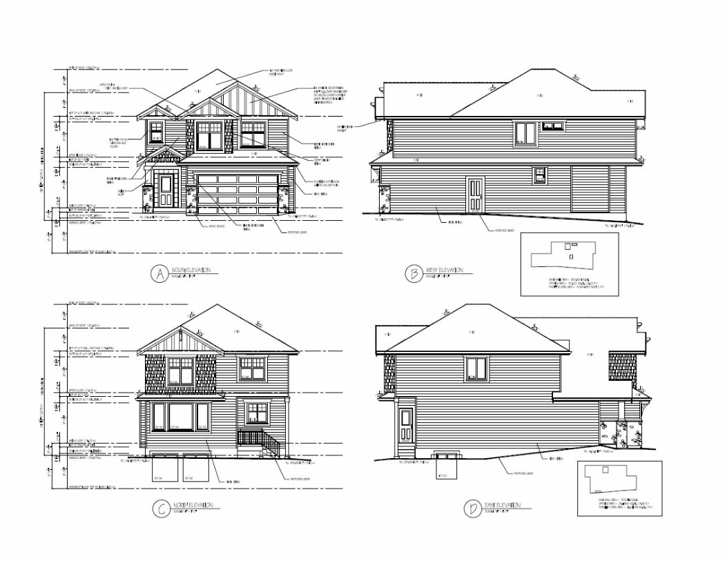
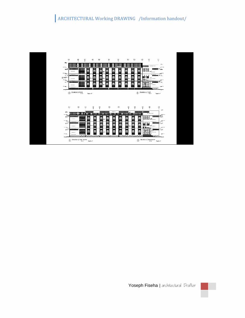
3. ELEVATIONS
An elevation is an orthographic drawing of the sides of the structure. The term “elevation" usually refers to
an outside elevation
Various interior elevations are included in a set of plans (kitchen, bathroom, etc.), but these are referred to
as details. The purpose of an elevation is to show the finished appearance of the structure and vertical
height dimensions. Four Elevations are usually drawn, one for each of the sides of the house.
A. Required Information
Identification of the specific side of the house elevation
Grade line
Finish floor and ceiling levels (shown with phantom lines)
Windows and doors
Foundation (shown with hidden lines)
Vertical dimensions of important features
Porches, desks, patios, and material symbols
B. Elevation Identification
Each elevation must be identified. Two commonly used methods are (Front, Rear, Right
Side, and Left Side), or (North, South, East, and West). The first method is the preferred.
Right and left sides are determined by facing the front of the building. Identify each
elevation directly below the drawing to avoid confusion.
C. Grade Lines, Floor and Ceilings
1. The reference point for most elevations is the grade line. All features that are below the
grade line should be shown as hidden lines. Examples are foundation, footings and
window wells.
2. Floor to ceiling height should be shown. Two method are used:
a. Finished floor to finished ceiling distances. The typical distance from finished floor
to finished ceiling is 2.80m – 3.00m.
b. The construction dimension or distance is from the top of the sub‐floor to the top
of the wall plate. In this case the construction dimension for the first floor is 8'‐1
1/8".
Sometimes second floors are 7'‐7 1/8". Carpenters prefer this method because it
saves them doing the calculations.
c. The top of the foundation must be 8" above the grade to protect framing members
from moisture.
d. Garage floors may be slightly higher than grade but should be at least 4" lower
than an interior when the garage is attached to the house.
D. Walls, Windows, Doors
1. Exterior walls, windows, and doors must be shown on elevations.
2. It is customary to make top of windows the same height as top of doors.
3. Usual door height is 6'‐ 8" from the top of the sub‐floor to the lower face of the head jam.
4. Windows and doors should receive DETAILED presentation on elevations.
E. Roof Features
1. Roof style, pitch, chimney height, and chimney size are shown.
2. The roof pitch may be indicated using the fractional pitch or slope triangle.
3. Chimney height above the highest point should be dimensioned and is usually 2’‐0" above the
ridge.
4. Chimney flashings, roof covering material, and gable ventilation area shown.
F. Dimensions, Notes, and Symbols
1. Vertical height dimensions are shown including:
a. footing thickness
b. distance from footing to grade

ARCHITECTURAL Working DRAWING /Information handout/
Yoseph Fiseha |
c. finished floor to finished ceiling
d. overhang width
e. height of top of windows and doors
f. height of chimney above roof
2. Appropriate notes should be included where needed:
a. grade information
b. exterior wall material notation
c. roof covering material notation
d. fascia and flashing material
3. Symbols should be appropriately shown
a. roof pitch symbol
b. exterior wall material symbols
c. window
d. swing symbols (if needed)

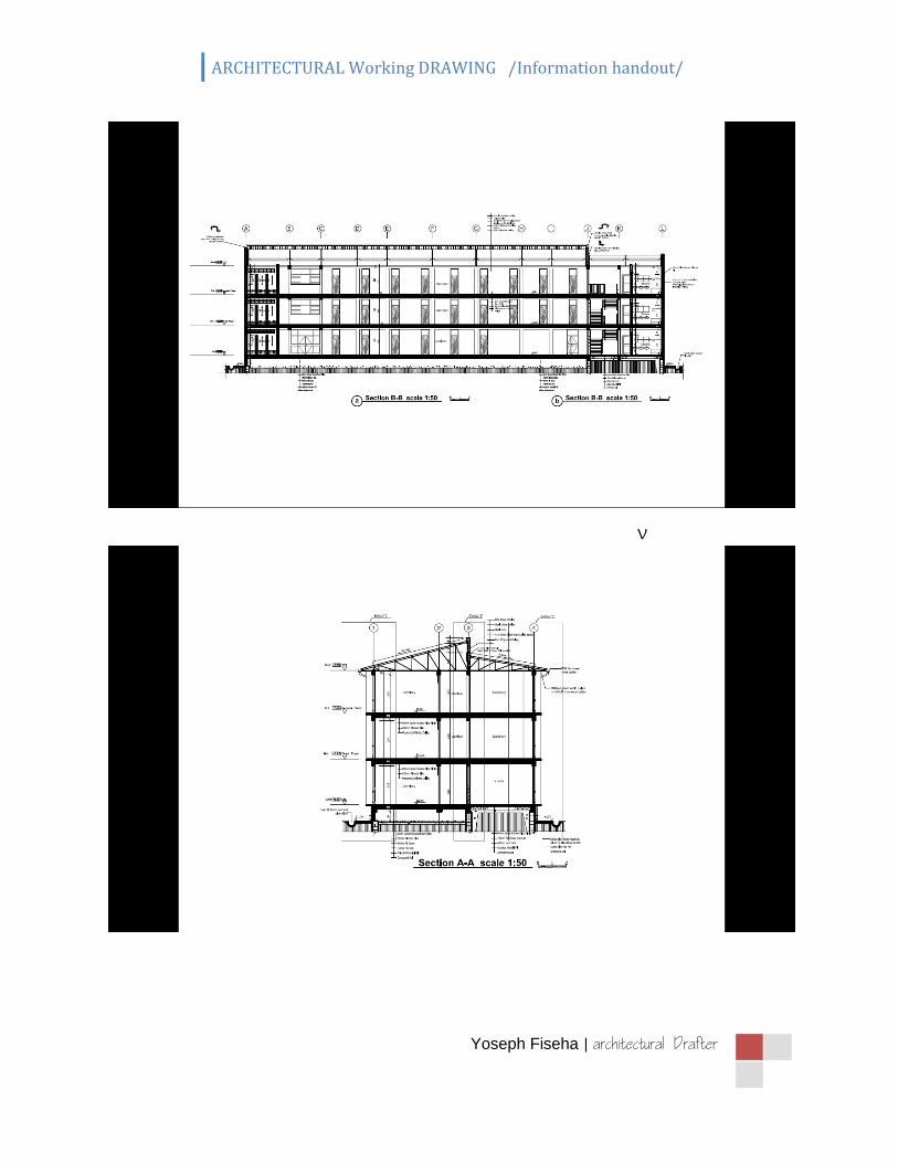
4. SECTIONS
Section drawing is an orthographic projection that has been cut apart to show interior features.
PURPOSE
1. Describe the construction materials of the structure.
2. Describe method of construction. (General assembly of different parts)
3. Show interior design elements
4. Clearly depict the structural conditions existing in the building.
Generally, sectional drawings describe constructions materials and methods especially those things
hidden by wall or ceiling sheathing and are often the easiest way to describe a complex detail to a
contractor.
TYPES OF SECTIONS
1. STRUCTURAL SECTION
A structural section shows the entire building construction and also shows the interior spaces in
elevation.
a. BUILDING LONGUTIDNAL SECTION
Section takes on the long axis of the building
b. BUILDING CROSS-SECTION
Section taken across its narrower dimension.
2. WALL SECTION
Shows the construction of a typical wall to a larger scale than the structural section
3. DETAIL SECTION
Section views cut through a small segment of a building and drawn with enlarged scale
This are some of part are drawn in detail drawing
A. Window and door section
B. Stair section
C. Chimney section
D. Structural detail section
Sectional drawings are drawn in a scale of 1:50 or 1:100 in common working drawing but detail
section drawing are drawn in a scale 1:20 or 1:25 package. Sections are basically drawn referenced on plans
and elevations.
PLACEMENT OF CUTTING PLANE
The cutting plane best to be passes through;
Stairs to show vertical movement
Window and door to show detail in opening
Important interior spaces to show the interior spaces well
Generally - depends on the need to convey the greatest amount of information and clarity for those
building structures.
ARCHITECTURAL Working DRAWING /Information handout/
Yoseph Fiseha |
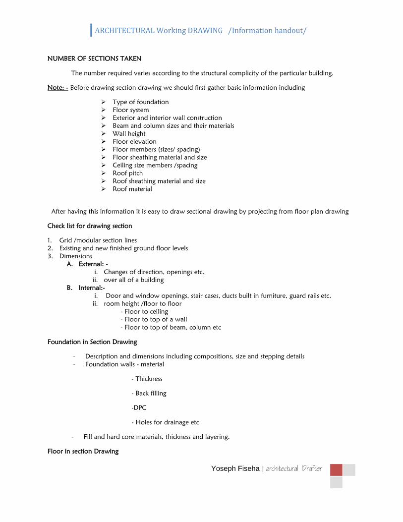
NUMBER OF SECTIONS TAKEN
The number required varies according to the structural complicity of the particular building.
Note: - Before drawing section drawing we should first gather basic information including
Type of foundation
Floor system
Exterior and interior wall construction
Beam and column sizes and their materials
Wall height
Floor elevation
Floor members (sizes/ spacing)
Floor sheathing material and size
Ceiling size members /spacing
Roof pitch
Roof sheathing material and size
Roof material
After having this information it is easy to draw sectional drawing by projecting from floor plan drawing
Check list for drawing section
1. Grid /modular section lines
2. Existing and new finished ground floor levels
3. Dimensions
A. External: -
i. Changes of direction, openings etc.
ii. over all of a building
B. Internal:-
i. Door and window openings, stair cases, ducts built in furniture, guard rails etc.
ii. room height /floor to floor
- Floor to ceiling
- Floor to top of a wall
- Floor to top of beam, column etc
Foundation in Section Drawing
- Description and dimensions including compositions, size and stepping details
- Foundation walls - material
- Thickness
- Back filling
-DPC
- Holes for drainage etc
- Fill and hard core materials, thickness and layering.
Floor in section Drawing

ARCHITECTURAL Working DRAWING /Information handout/
Yoseph Fiseha |
- Thickness, composition, hard core, reinforced slab screed, floor finish
- Intermediate floor construction / type, material, dimensions, fixing, ceiling etc /
Wall in section Drawing
Exterior / interior wall-type, materials, dimensions, fixing finishes.
- Door and door frames, window and window frames
- Dimensions and description (referenced to schedule)
ARCHITECTURAL Working DRAWING /Information handout/
Yoseph Fiseha |
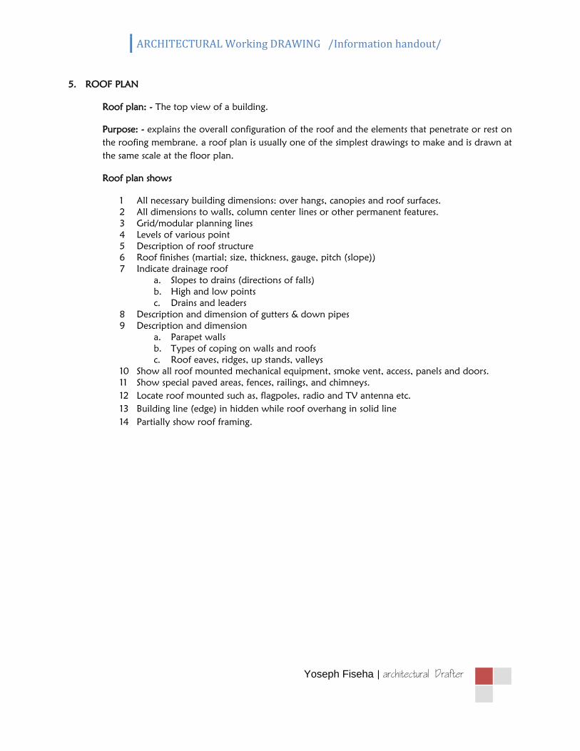
5. ROOF PLAN
Roof plan: - The top view of a building.
Purpose: - explains the overall configuration of the roof and the elements that penetrate or rest on
the roofing membrane. a roof plan is usually one of the simplest drawings to make and is drawn at
the same scale at the floor plan.
Roof plan shows
1 All necessary building dimensions: over hangs, canopies and roof surfaces.
2 All dimensions to walls, column center lines or other permanent features.
3 Grid/modular planning lines
4 Levels of various point
5 Description of roof structure
6 Roof finishes (martial; size, thickness, gauge, pitch (slope))
7 Indicate drainage roof
a. Slopes to drains (directions of falls)
b. High and low points
c. Drains and leaders
8 Description and dimension of gutters & down pipes
9 Description and dimension
a. Parapet walls
b. Types of coping on walls and roofs
c. Roof eaves, ridges, up stands, valleys
10 Show all roof mounted mechanical equipment, smoke vent, access, panels and doors.
11 Show special paved areas, fences, railings, and chimneys.
12 Locate roof mounted such as, flagpoles, radio and TV antenna etc.
13 Building line (edge) in hidden while roof overhang in solid line
14 Partially show roof framing.
ARCHITECTURAL Working DRAWING /Information handout/
Yoseph Fiseha |
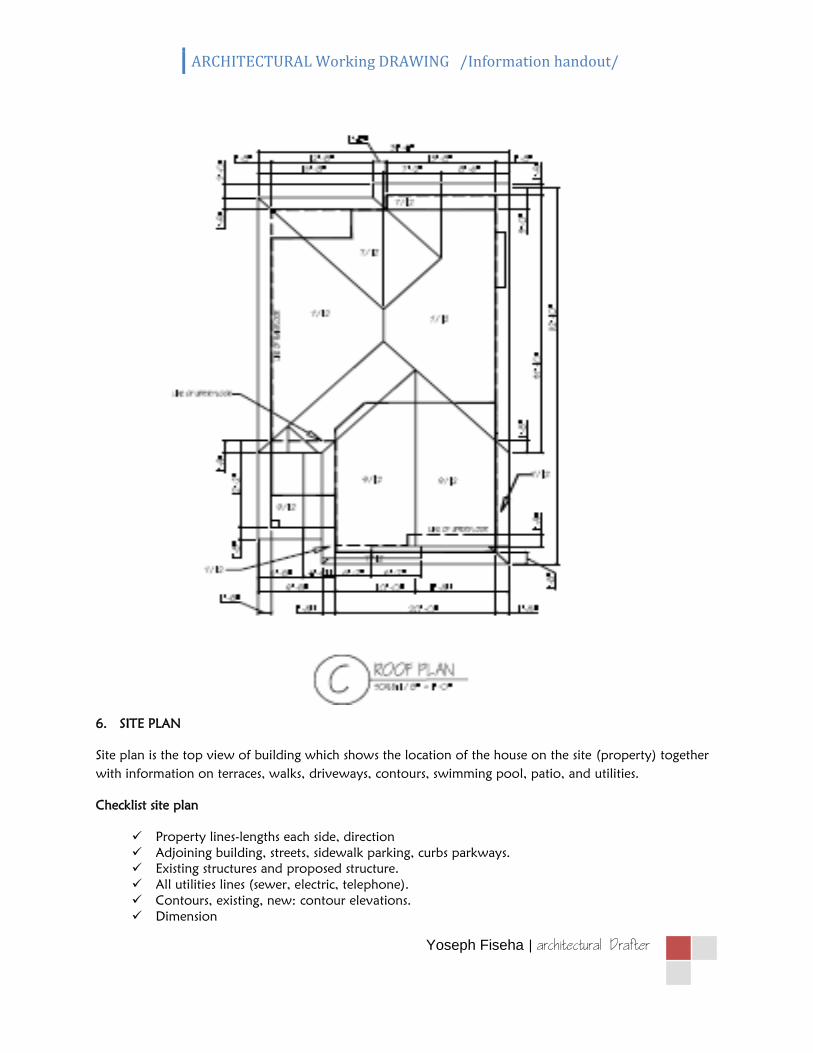
6. SITE PLAN
Site plan is the top view of building which shows the location of the house on the site (property) together
with information on terraces, walks, driveways, contours, swimming pool, patio, and utilities.
Checklist site plan
Property lines-lengths each side, direction
Adjoining building, streets, sidewalk parking, curbs parkways.
Existing structures and proposed structure.
All utilities lines (sewer, electric, telephone).
Contours, existing, new: contour elevations.
Dimension

ARCHITECTURAL Working DRAWING /Information handout/
Yoseph Fiseha |
- Property lines
- Side yards, pears, front yard
- Street center line
- Length of walks and walls
- Dimensions of building to property line
Fences, structural retaining walls, area ways and pools
North arrow
Drainage lines
All existing paving weather to remain or to remove, new paving, parking lots, steps, platforms,
signs, play fields, foundations, etc
Tree, shrubs, if exist
Legend showing all symbols and materials and materials used on the site.
ARCHITECTURAL Working DRAWING /Information handout/
Yoseph Fiseha |
ARCHITECTURAL Working DRAWING /Information handout/
Yoseph Fiseha |
V

ARCHITECTURAL Working DRAWING /Information handout/
Yoseph Fiseha |