APPLICATION OF TENSIONED PULLOUT TESTS TO INVESTIGATE THE EFFECT OF PRESTRESSING WIRE INDENT...
16
Holste, Haynes, Peterman, Beck and Wu 2014 PCI/NBC APPLICATION OF TENSIONED PULLOUT TESTS TO INVESTIGATE THE EFFECT OF PRESTRESSING WIRE INDENT GEOMETRY ON BOND AND SPLITTING CHARACTERISTICS Joseph Holste, PhD, Dept. of Civil Engineering, Kansas State University Mark Haynes, Dept. of Industrial Systems Manufacturing Engineering, Kansas State University Robert Peterman, PhD, P.E., Dept. of Civil Engineering, Kansas State University B. Terry Beck, PhD, Dept. of Mechanical Engineering, Kansas State University Chih-Hang John Wu, PhD, Dept. of Industrial Systems Manufacturing Engineering, Kansas State University Abstract: An experimental program was conducted at Kansas State University to study the geometric properties of indented prestressing wires that induce splitting of the surrounding concrete. Tensioned wire pullout specimens using 5.32-mm-diameter prestressing wires were tested to investigate the angles of the indent that caused the specimens to split. Indent patterns were custom machined to various unique geometries on smooth prestressing wire. The custom geometries provided controlled experiments analyzing various geometrical features influence in concrete splitting. Each test consisted of a single wire that was bonded 2.5 inches in a rectangular specimen. The wire was tensioned to 75% of its ultimate strength before concrete was cast in a mold around it. The force in the wire was decreased after the concrete had reached strength of 4,500 psi. The force in the wire above and below the specimen was measured along with the amount of slip on each end of the specimen. Different geometry patterns were shown to cause the specimens to split as the wire moved through the specimen. Controlled variation in the machining of indent geometries allowed for detection as to what geometrical features are prone to cause splitting and which geometrical features increase bonding capability. Keywords: Prestress, Wire, Splitting, Pullout, Tensioned, Indent
Transcript of APPLICATION OF TENSIONED PULLOUT TESTS TO INVESTIGATE THE EFFECT OF PRESTRESSING WIRE INDENT...

Holste, Haynes, Peterman, Beck and Wu 2014 PCI/NBC
APPLICATION OF TENSIONED PULLOUT TESTS TO INVESTIGATE THE
EFFECT OF PRESTRESSING WIRE INDENT GEOMETRY ON BOND AND
SPLITTING CHARACTERISTICS
Joseph Holste, PhD, Dept. of Civil Engineering, Kansas State University
Mark Haynes, Dept. of Industrial Systems Manufacturing Engineering, Kansas State
University
Robert Peterman, PhD, P.E., Dept. of Civil Engineering, Kansas State University
B. Terry Beck, PhD, Dept. of Mechanical Engineering, Kansas State University
Chih-Hang John Wu, PhD, Dept. of Industrial Systems Manufacturing Engineering, Kansas
State University
Abstract:
An experimental program was conducted at Kansas State University to study the
geometric properties of indented prestressing wires that induce splitting of the
surrounding concrete. Tensioned wire pullout specimens using 5.32-mm-diameter
prestressing wires were tested to investigate the angles of the indent that caused the
specimens to split. Indent patterns were custom machined to various unique
geometries on smooth prestressing wire. The custom geometries provided controlled
experiments analyzing various geometrical features influence in concrete splitting.
Each test consisted of a single wire that was bonded 2.5 inches in a rectangular
specimen. The wire was tensioned to 75% of its ultimate strength before concrete
was cast in a mold around it. The force in the wire was decreased after the concrete
had reached strength of 4,500 psi. The force in the wire above and below the
specimen was measured along with the amount of slip on each end of the specimen.
Different geometry patterns were shown to cause the specimens to split as the wire
moved through the specimen. Controlled variation in the machining of indent
geometries allowed for detection as to what geometrical features are prone to cause
splitting and which geometrical features increase bonding capability.
Keywords: Prestress, Wire, Splitting, Pullout, Tensioned, Indent

Holste, Haynes, Peterman, Beck and Wu 2014 PCI/NBC
2
Introduction
Tensioned wire pullout tests have been shown by Holste et al.1 to provide an accurate
representation of the transfer of prestress into a concrete member. This representation was
found to show what types of commercial indents caused splitting by Holste et al.2. The
testing of commercially made indent patterns limited the variables that could be looked at
due to the similarities between the indents. These wires are mainly used in the production of
concrete railroad ties which consists of multiple wires being arranged along the cross section
of the railroad tie. This research project looks at the testing of custom machined indents
using a tensioned wire pullout test. This information can be useful in using pretressing wire
in other applications then railroad ties. Prestressing wires could be used for the production of
thinner panels that are too thin to be produced using strand.
Problem Statement
Commercial reinforcement wires are all individually unique. Each commercial
reinforcement wire has varying indent depth, width, edge wall angle, and overall shape.
With every wire uniquely different it is difficult to perform a controlled experiment on the
influence of individual geometrical features by using commercially available reinforcements.
Since commercial reinforcements have multiple parameter variations, testing these wires
only shows the influence of these multiple parameter changes and not the influence of a
single parameter.
Objective
The solution to this problem is to make custom reinforcement wires where the variation in
geometry of the indent pattern is controlled. By manufacturing several reinforcements with
the same geometry and only varying indent edge angle, or the same geometry with only
varying indent depth. It is possible to determine the influence of the individual parameter.
This can lead to a better understanding as to what indent edge wall angles and indent depths
result in a high propensity for fracture. The custom machined reinforcements may also lead
to a better understanding as what an ideal indent geometry should be in order to minimizes
the transfer length and the propensity for fracture for the pre-stressed concrete railroad ties.
As machining custom reinforcement geometries is expensive, pre-tensioned pullout
experiments are an ideal testing procedure for custom machined geometries. By using pre-
tensioned pullout experiments the reinforcements made only need to be 5 inches in length to
conduct a pre-tensioned pullout experiment. This is advantageous in comparison to casting
the samples into concrete prisms or concrete cross ties as the samples would need to be
several feet in length.
Wire Machining Setup
For these experiments 2 parameters are considered – indent depth and indent edge wall angle.
The indent patterns were machined into a smooth non-indented sample of prestressing
reinforcement wire. The reinforcement wire had a Rockwell C hardness of 45. The wire
diameter is 5.32mm. The indents were machined with a single pass from a 1/8” end diameter
end mill. In order to make indents with different edge wall angles, custom made end mills
were used. The end mills had 6 different chamfer angles on them to machine 6 different edge
wall angles.
Holste, Haynes, Peterman, Beck and Wu 2014 PCI/NBC
3
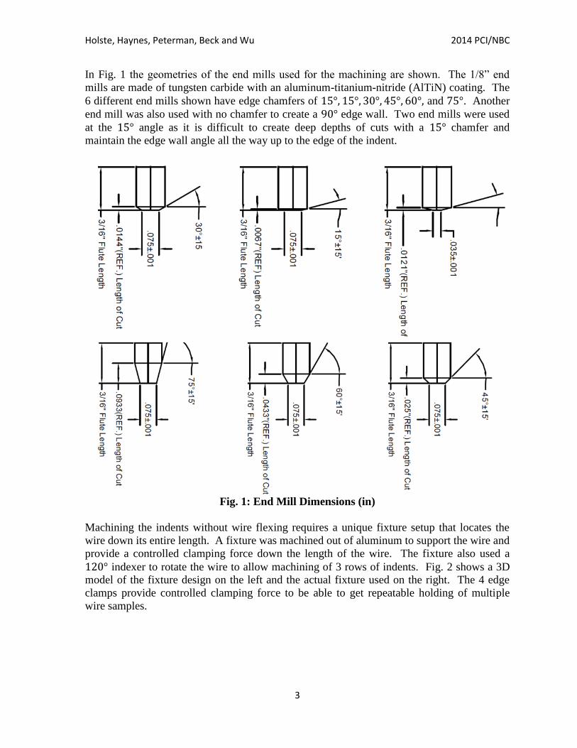
In Fig. 1 the geometries of the end mills used for the machining are shown. The 1/8” end
mills are made of tungsten carbide with an aluminum-titanium-nitride (AlTiN) coating. The
6 different end mills shown have edge chamfers of and . Another
end mill was also used with no chamfer to create a edge wall. Two end mills were used
at the angle as it is difficult to create deep depths of cuts with a chamfer and
maintain the edge wall angle all the way up to the edge of the indent.
Fig. 1: End Mill Dimensions (in)
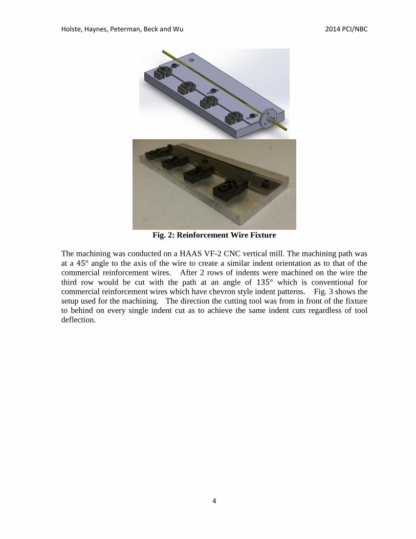
Machining the indents without wire flexing requires a unique fixture setup that locates the
wire down its entire length. A fixture was machined out of aluminum to support the wire and
provide a controlled clamping force down the length of the wire. The fixture also used a
indexer to rotate the wire to allow machining of 3 rows of indents. Fig. 2 shows a 3D
model of the fixture design on the left and the actual fixture used on the right. The 4 edge
clamps provide controlled clamping force to be able to get repeatable holding of multiple
wire samples.
Holste, Haynes, Peterman, Beck and Wu 2014 PCI/NBC
4
Fig. 2: Reinforcement Wire Fixture
The machining was conducted on a HAAS VF-2 CNC vertical mill. The machining path was
at a angle to the axis of the wire to create a similar indent orientation as to that of the
commercial reinforcement wires. After 2 rows of indents were machined on the wire the
third row would be cut with the path at an angle of which is conventional for
commercial reinforcement wires which have chevron style indent patterns. Fig. 3 shows the
setup used for the machining. The direction the cutting tool was from in front of the fixture
to behind on every single indent cut as to achieve the same indent cuts regardless of tool
deflection.

Holste, Haynes, Peterman, Beck and Wu 2014 PCI/NBC
5
Fig. 3: Machining Setup
Fig. 4 shows the 12 machined samples. The machined length is 5 inches long on a wire
sample with a total length of 37 inches. This is to give enough room for the sample to be
chucked into the pre-tensioned pullout equipment.
Fig. 4: Machined Reinforcements

Holste, Haynes, Peterman, Beck and Wu 2014 PCI/NBC
6
Fig. 5 shows the machined reinforcements through a microscope. The indents have a highly
reflective surface due to the machining in comparison to the dark color of the natural oiled
surface of the wire. The indent depths were attempted to be made as close as possible from
wire to the next, however, with the indents only being in the range of 100-400 microns in
depth it is considerably difficult to get perfect repeatability through multiple fixture
locations. As such it is necessary to measure the machined reinforcements to confirm their
dimensions.
Fig. 5: Microscope View of Machined Reinforcements
3
The wires were scanned on a custom developed 3D scanner. The scanner used a laser
displacement sensor connected to a linear traverse and held the wire with a 6-jaw chuck
connected to a rotary table. The wire was rotated while the laser was moved across the
length of the wire to develop high resolution 3D scans. Fig. 6 shows the setup for the wire
scanning process.

Holste, Haynes, Peterman, Beck and Wu 2014 PCI/NBC
7
Fig. 6: Wire Scanning Setup
Fig. 7 shows the resultant 3D model from the scanning process. These 3D models allow for
cross verification of the indent geometries created allowing for imperfections in the
machining process to be taken into account during the testing of the wires. From these high
resolution surface profile captures the critical dimensions of the reinforcement wire were re-
measured. Table 1 shows the indent depths for each of the indents.
Fig. 7: 3D Models of Machined Wires

Holste, Haynes, Peterman, Beck and Wu 2014 PCI/NBC
8
Table 1: Indent Depth for Each Indent Angle (in mm)3
Tensioned Pullout Testing
The wires that were machined were tested using a tensioned wire pullout test as described by
Holste3. The wires were tensioned to 75% of their ultimate capacity before the specimens
were cast. After the specimens were cast and had cured to a strength of 4,500 psi, the force
in the wire above the specimen was reduced by turning the jack that the wire ran through.
This reduction of force caused the wire to slip through the concrete specimen. Force above
and below the specimen was measured using S-type load cells. The end-slip above and
below the specimen was also measured during testing. The specimens cast were 3.5-inch by
1.75-inch rectangles with a height of 2.5 inches. Each specimen was instrumented with an
internally cast vibrating wire strain gauge. These gauges were used to measure the lateral
expansion of the specimen along the gauge as the wire was detensioned. Fig. 8 shows the
specimen dimensions, wire location and gauge location. Fig. 9 shows one of the two testing
frames that were used. Fig. 10 shows the specimen form prior to casting of the specimen.
Fig. 8: Specimen Dimensions and Vibrating Wire Strain Gauge Location
3
15ᵒ 30ᵒ 45ᵒ 60ᵒ 75ᵒ 90ᵒ
Shallow 0.310 0.158 0.156 0.142 0.286 0.142
Deep 0.400 0.261 0.245 0.245 0.387 0.217

Holste, Haynes, Peterman, Beck and Wu 2014 PCI/NBC
9
Fig. 9: Test Frame Setup
3
Fig. 10: Test Specimen Forms Before Casting
3

Holste, Haynes, Peterman, Beck and Wu 2014 PCI/NBC
10
The concrete mix used during testing was identical to the mix used by Holste et al.2. The mix
consisted of Type III cement, sand, 3/8-inch gradation pea gravel, water and a high range
water reducer. Table 2 shows the mix proportions used.
Table 2: Mix Proportions3
Results and Conclusions
Shallow and deep indent wires for each angle were tested using the same concrete batch. The
readings from the load cell and end-slip measurements were used to calculate the end-slip
and bond stress for each set of tests. The bond stress and lateral expansion for each test was
plotted. The max crack width for each specimen was also recorded if the specimen cracked.
Fig. 11 shows the results from the deep 30-degree indent test. Fig. 12 shows the cracked
specimen after testing. Fig. 13 shows the shallow and deep 30-degree indent bond stress
results for the two tests.
Fig. 11: Bond Stress and Lateral Expansion Relationship for Deep 30-degree Indent
3
Material Quantity per Batch (0.25 ft3
)
Type-III Cement 9 lbs.
Sand 16 lbs.
3/8” Aggregate 12 lbs.
Water 2.88 lbs.
Type-F HRWR 25 ml

Holste, Haynes, Peterman, Beck and Wu 2014 PCI/NBC
11
Fig. 12: Deep 30-degree Indent Specimen after Testing
3
Fig. 13: Bond Stress versus Bottom Slip Relationship for Both 30-degree Indents
3

Holste, Haynes, Peterman, Beck and Wu 2014 PCI/NBC
12
Fig. 14 shows the results from the shallow 45-degree indent. The specimen didn’t crack
during testing as seen in Fig. 15. The results from the two 45-degree indents tests are shown
Fig. 16. The results from all of the shallow indents are shown in Fig. 17. Fig.18 shows the
results from all of the deep indents. The deeper indents showed higher bond stresses than the
shallower indents. The higher bonding ability of the deep indents matched with the splitting
of the specimens.
Fig. 14: Bond Stress and Lateral Expansion Relationship for Shallow 45-degree Indent
3

Holste, Haynes, Peterman, Beck and Wu 2014 PCI/NBC
13
Fig. 15: Shallow 45-degree Indent Specimen after Testing
3
Fig. 16: Bond Stress versus Bottom Slip Relationship for Both 45-degree Indents
3

Holste, Haynes, Peterman, Beck and Wu 2014 PCI/NBC
14
Fig. 17: Bond Stress versus Bottom Slip Relationship for all Shallow Indents
3
Fig.18: Bond Stress versus Bottom Slip Relationship for all Deep Indents
3

Holste, Haynes, Peterman, Beck and Wu 2014 PCI/NBC
15
Table 3 shows the crack widths for each of the tests. The deeper indents were shown to
produce wider cracks on the top surface of the specimens.
Table 3: Crack Widths for Each Indent (in inches)3
Angle
Shallow
Indent
Deep
Indent
15-Degree 0.016 0.025
30-Degree 0.003 0.008
45-Degree No Crack 0.012
60-Degree No Crack 0.003
75-Degree 0.005 0.012
90-Degree 0.004 0.008
The results from the testing showed that the deeper indents caused higher lateral expansion.
The vibrating wire strain gauges showed lateral expansion of the specimen prior to cracking.
The higher lateral expansion was shown to cause all of the deeper indents to crack the test
specimen. The shallower indents with 45 and 60-degree indents didn’t cause cracking. This
information provides a basis for the development of an indent that is less likely to cause
splitting in prestressed members. These results can be used to help understand the cracking
nature of prestressed members and would be useful in using prestressing wires to produce
thinner panels.
Acknowledgements
The authors would like to thank the Federal Railroad Administration (FRA) for providing the
majority of the funding that made this research possible. Additionally, LB Foster/CXT
Concrete Ties has donated extensive resources, including all of the reinforcements, to make
the project a success. The researchers would also like to thank Drs. Hailing Yu and David
Jeong at the John A. Volpe National Transportation Systems Center for their valuable
suggestions and parallel analysis work. Finally, the authors wish to thank the
Precast/Prestressed Concrete Institute (PCI) for establishing an industry advisory panel to the
project.
References
1. Holste, J.R., Peterman, R.J., Bodapati, N.B., Beck, B.T., Wu, C.H.J., “Transfer Bond Test
used to Predict Transfer Length of Concrete Railroad Ties,” Proceedings of the ASME 2013
Rail Transportation Division Fall Technical Conference, RTDF2013-4726
2. Holste, J.R., Haynes, M., Peterman, R.J., Beck, B.T., Wu, C.H.J., “Tensioned Pullout Test
Used To Investigate Wire Splitting Propensity in Concrete Railroad Ties,” Proceedings of
the 2014 Joint Rail Conference, JRC2014-3833.

Holste, Haynes, Peterman, Beck and Wu 2014 PCI/NBC
16
3. Holste, J.R. “Experimental Determination Of Prestressing Wire Bond And Splitting
Propensity Characteristics Through Tensioned Pullout Tests,” Dissertation, Kansas State
University, 2014.