Appraisal of land use/land cover of mangrove forest ecosystem using support vector machine

This article appeared in a journal published by Elsevier. The attachedcopy is furnished to the author for internal non-commercial researchand education use, including for instruction at the authors institution
and sharing with colleagues.
Other uses, including reproduction and distribution, or selling orlicensing copies, or posting to personal, institutional or third party
websites are prohibited.
In most cases authors are permitted to post their version of thearticle (e.g. in Word or Tex form) to their personal website orinstitutional repository. Authors requiring further information
regarding Elsevier’s archiving and manuscript policies areencouraged to visit:
http://www.elsevier.com/copyright

Author's personal copy
Vibration based fault diagnosis of monoblock centrifugal pump using decision tree
N.R. Sakthivel a, V. Sugumaran b,*, S. Babudevasenapati a
a Department of Mechanical Engineering, Amrita School of Engineering, Ettimadai, Coimbatore 641 105, Indiab Department of Mechanical Engineering, SRM University, Chennai, India
a r t i c l e i n f o
Keywords:Monoblock centrifugal pumpC4.5 algorithmFault diagnosisStatistical features
a b s t r a c t
Monoblock centrifugal pumps are widely used in a variety of applications. In many applications the roleof monoblock centrifugal pump is critical and condition monitoring is essential. Vibration based contin-uous monitoring and analysis using machine learning approaches are gaining momentum. Particularlyartificial neural networks, fuzzy logic were employed for continuous monitoring and fault diagnosis. Thispaper presents the use of C4.5 decision tree algorithm for fault diagnosis through statistical featureextracted from vibration signals of good and faulty conditions.
� 2009 Elsevier Ltd. All rights reserved.
1. Introduction
Centrifugal pump plays an important role in industries and itrequires continuous monitoring to increase the availability of thepump. The pumps are the key elements in food industry, wastewater treatment plants, agriculture, oil and gas industry, paperand pulp industry, etc. In a monoblock centrifugal pump, bearing,seal and impeller are the critical components that directly affectthe desired pump characteristics. In a monoblock centrifugalpump, defective bearing, defective seal, defect on the impellerand cavitation cause more number of serious problems such asabnormal noise, leakage, high vibration, etc. Cavitation can causemore undesirable effects, such as deterioration of the hydraulicperformance (drop in head-capacity and efficiency), damage ofthe pump by pitting, erosion and structural vibration (Alfayez,Mba, & Dyson, 2005). Vibration signals are widely used in condi-tion monitoring of centrifugal pumps (Peck & Burrows, 1994). Faultdetection is achieved by comparing the signals of monoblock cen-trifugal pump running under normal and faulty conditions. Thefaults considered in this study are bearing fault (BF), seal fault(SF), impeller fault (IF), bearing and impeller fault (BFIF) togetherand cavitation (CAV). In conventional condition monitoring, thecommonly used method is vibration analysis in frequency domainthrough Fast Fourier Transform (FFT). Seismic or piezo-electrictransducers are used to measure the vibration. The level of vibra-tion can be compared with historical baseline value to assess theseverity. Interpreting the vibration signal is a complex process thatrequires specialized training and experience. Commonly usedtechnique is to examine the individual frequencies present in thesignal. These frequencies correspond to certain mechanical compo-
nent or certain malfunction. By examining these frequencies andtheir harmonics, the analyst can identify the location, type of prob-lem and the root cause as well (Cempel, 1988). Nowadays, theapplication of machine learning for fault diagnosis is more com-mon as an alternative to conventional methods. It is largely dueto increased availability of computational resources and develop-ment in algorithms. Also for complex systems involving manycomponents, it is difficult to compute characteristic fault frequen-cies. Even if characteristic frequencies are available the vibrationsignals are highly non-stationary in nature and FFT based methodsare suited only for stationery processes. In the machine learningapproach the data acquisition system is used to capture the vibra-tion signals (Kong & Chen, 2004; McFadden & Smith, 1984; Raja-karunakaran, Venkumar, Devaraj, & Surya Prakasa Rao, 2008).From the vibration signal relevant features can be extracted andclassified using a classifier (Koo & Kim, 2000; Sanz, Perera, & Huer-ta, 2007; Wang & Hu, 2006).
Alfayez et al. (2005) presented where acoustic emission hasbeen applied for detecting incipient cavitation and determiningthe best efficiency point (BEP) of a centrifugal pump are based onnet positive suction head (NPSH) and performance tests. Peckand Burrows (1994) discussed rule based expert system using his-torical vibration data monitored from compressors, pumps andelectric motors and a heuristic artificial neural network systemwere designed and evaluated to extract and identify useful pat-terns and trends in the vibration signals. Cempel (1988) presentedvibroacoustical (VA) diagnostic in technical diagnostics and at dif-ferent stages of the machinery lifetime. Vibroacoustical (VA) diag-nostic consists of two parts. The first part was the creation orchoice of a proper VA symptom to a given fault and the establish-ment of the most effective type of ‘‘condition-symptom” relationfor a given case. The second part was condition recognition andforecasting where the confidence level depends on the appliedmodel and the inference method.
0957-4174/$ - see front matter � 2009 Elsevier Ltd. All rights reserved.doi:10.1016/j.eswa.2009.10.002
* Corresponding author. Tel.: +91 9486094486.E-mail addresses: [email protected] (N.R. Sakthivel), [email protected]
com (V. Sugumaran), [email protected] (S. Babudevasenapati).
Expert Systems with Applications 37 (2010) 4040–4049
Contents lists available at ScienceDirect
Expert Systems with Applications
journal homepage: www.elsevier .com/locate /eswa

Author's personal copy
Wang and Chen (2007) proposed the synthetic detection indexwith fuzzy neural network to evaluate the sensitivity of nondimensional symptom parameters for detecting faults in centrifu-gal pump. Rajakarunakaran et al. (2008) developed a model forthe fault detection of centrifugal pumping system using two differ-ent artificial neural network approaches, namely feed forward net-work with back propagation algorithm and binary adaptiveresonance network (ART1). The performance of the developed backpropagation and ART1 model were tested for a total of seven cate-gories of faults in the centrifugal pumping system. Classificationaccuracy of 99.3% was achieved. Wang and Hu (2006) used fuzzylogic principle as classifier with the features extracted from thevibration signals of the pump.
Kong and Chen (2004) proposed a new combined diagnosticsystem for triplex pump based on wavelet transform, fuzzy logic,neural network. The developed diagnostic system consists of fourparts. The first part was wavelet transform in which multi resolu-tion analysis was employed. The second part was for asymptoticspectrum estimation of the characteristic variable. The third partwas employed for characteristic variable fuzzified in simulatingfuzzy inference using incomplete information. The fourth partwas the neural network trained with fuzzified characteristic vari-able for triplex pump failure diagnosis. Yuan and Chu (2006) dis-cussed the fault diagnosis based on support vector machine. It isbinary tree classifier composed of several two class classifiers.The effectiveness of the method is verified by the application tothe fault diagnosis for turbo rotor pump. Zhang, Asakura, Xu, andXu (2003) introduced a fault diagnosis system using fuzzy neuralnetwork based on the series of standard fault pattern pairings be-tween fault symptoms and fault. Fuzzy neural networks weretrained to memorize these standard pattern pairs and it adoptsbidirectional association to produce 97.3% classification accuracy(see Fig. 1).
Sanz et al. (2007) presented a technique for monitoring the con-dition of rotating machinery from vibration analysis that combinesthe capability of wavelet transform to treat the transient signals
with the ability of auto associative neural networks to extract fea-tures of datasets in an unsupervised mode. Trained and configurednetworks with wavelet transform coefficients of non faulty signalsare used as a method to detect the novelties or anomalies of faultysignals. Koo and Kim (2000) introduced wigner distribution foranalyzing vibration signals and developed an expert system forvibration monitoring and diagnostics for rotating machines usingback propagation neural network. A classification accuracy of81.25% was achieved in finding abnormalities of pump. Yuan andChu (2007) presented a method that jointly optimises the featureselection and support vector machine parameters. A hybrid vectorthat describes both the fault features and the support vector ma-chine parameters was taken as the constraint condition. This newmethod can select the best fault features in a shorter time and im-prove the performance of support vector machine classifier.
Artificial neural network gives 97.3% classification accuracy. It isa very good result. However, training of an artificial neural networkclassifier is complex and time consuming. The robustness andeffectiveness of fuzzy classifier depends on the rules suggestedby the experts or algorithms. Support vector machines also per-form very well in classification. Feature selection has to be carriedout through some other algorithms. It increases the computationaltime.
To overcome the above difficulties, researchers are having con-stant lookout for a classifier which will give very high classificationaccuracy with simple operation and does feature selection andclassification simultaneously. C4.5 decision tree algorithm seemsto be an algorithm which satisfies these conditions and it is beingused in many applications. To quote a few, Sun, Chen, and Li (2007)used principal component analysis (feature selection), C4.5 deci-sion tree and back propagation neural network (classification) tofault diagnosis of rotating machinery such as turbines and com-pressors. From the result, C4.5 and PCA-based diagnosis methodhas higher accuracy and needs less training time than back propa-gation neural network BPNN. Sugumaran, Muralidharan, andRamachandran (2007) illustrated the use of a decision tree thatidentified the best features from a given set of samples for classifi-cation. They used Proximal Support Vector Machine (PSVM), whichhas the capability to efficiently classify the faults using statisticalfeatures. The classification results of PSVM and SVM were com-pared and found that the classification efficiency of SVM was a lit-tle less than that of PSVM.
Polat and Günes (2009) proposed a novel hybrid classificationsystem based on C4.5 decision tree classifier and one-against-allapproach to classify the multi-class problems including dermatol-ogy, image segmentation and lymphography. Firstly C4.5 decisiontree has been used and achieved 84.48%, 88.79%, and 80.11% clas-sification accuracies for dermatology, image segmentation, andlymphography datasets, respectively. The proposed method basedon C4.5 decision tree classifier and one-against-all approach ob-tained 96.71%, 95.18%, and 87.95% for above datasets, respectively.Sugumaran and Ramachandran (2007) discussed condition moni-toring of roller bearing using decision tree. Statistical features likeminimum value, standard error and kurtosis, etc., were extractedfrom vibration signals there from a rule set is formed for fuzzy clas-sifier. This paper presented the use of decision tree to generate therules automatically from the feature set.
Data mining has been successfully applied to medical field suchas dermatology, image segmentation and lymphography (Polat &Günes, 2009). Some data mining algorithms have also been appliedto fault diagnosis of machines and induction motors (Tran, Yang,Oh, & Tan, 2009). For example, wavelet transform technique wasused in fault diagnosis of rotating machinery (Chen & Mo, 2004;Kong & Chen, 2004; Sanz et al., 2007). SVM, Fuzzy logic and neuralnetwork are widely used as classifiers. Walsh transform and SVMwere used in the fault diagnosis of shaft (Xiang, Zhou, An, Peng,Fig. 1. Flow chart of monoblock centrifugal pump fault diagnosis system.
N.R. Sakthivel et al. / Expert Systems with Applications 37 (2010) 4040–4049 4041

Author's personal copy
& Yang, 2008). Genetic programming was used in condition moni-toring to detect the fault in rotating machinery (Zhang, Jack, &Nandi, 2005). Decision tree algorithm was used as a classifier to de-tect the fault in rotating machinery, induction motor, bearing, shaftand gears (Sugumaran et al., 2007; Sugumaran & Ramachandran,2007; Sun et al., 2007). This is the only algorithm which can doboth feature extraction and classification simultaneously. There-fore, the decision tree C4.5 algorithm is used in this paper for faultdiagnosis of monoblock centrifugal pump.
The rest of the paper is organised as follows. In Section 2, exper-imental setup and experimental procedure is described. Section 3presents feature extraction from the time domain signal. In Section4, feature selection using decision tree is discussed. Section 5 de-scribes the training of the classifier and the classification accuracyis tested and subsequently Section 6 presents results of the exper-iment. Conclusions are presented in the final section.
2. Experimental studies
The main objective of the study is to find whether the mono-block centrifugal pump is in good condition or in faulty condition.If the pump is in faulty condition then the aim is to segregate thefaults into bearing fault, seal defect, impeller defect, seal andimpeller defect together and cavitation. This paper focuses on theuse of decision tree for fault diagnosis of monoblock centrifugalpump. Referring to Fig. 2, the monoblock centrifugal pump withsensor and data acquisition is discussed in the following topics un-der experimental setup and experimental procedure, respectively.
2.1. Experimental setup
The monoblock centrifugal pump for condition monitoring isshown in Fig. 2. The motor (2 hp) is used to drive the pump. Theflow at the inlet and the outlet of the pump can be adjusted bythe valve control system. The valve at the inlet of the pump is usedto make the pressure drop between the suction and at the eye ofthe impeller to simulate the cavitation. An acrylic pipe of one me-ter length is fitted on the inlet and at the outlet of the impeller tovisualize the cavitation. Piezo-electric type accelerometer is usedto measure the vibration signals. The accelerometer location isshown in Fig. 2, the accelerometer is mounted on the pump inlet
using adhesive. The accelerometer is connected to the signal condi-tioning unit where the signal goes through the charge amplifierand an analog to digital converter (ADC) and the signal is storedin the memory. Then the signal is processed from the memoryand it is used to extract different features.
2.2. Experimental procedure
The vibration signals are measured from the monoblock centrif-ugal pump working under normal condition at a constant rotationspeed of 2880 rpm. The performance characteristics were studiedfor the pump working under normal condition. Initially primingof the pump was done. After closing the delivery valve, the pumpwas started and the delivery valve was slowly opened. Readingssuch as suction head, delivery head, time required for 30 revolutionof energy meter disc and the time for 40 cm rise of water in mea-suring tank were tabulated. The experiment was repeated for dif-ferent delivery heads. The discharge, total head, percentage ofefficiency, and input power were calculated from the tabulated val-ues. Then the performance characteristic curves such as dischargevs. efficiency, discharge vs. total head, discharge vs. input powerwere plotted for the pump from the experimentally measured data.
The vibration signal from accelerometer mounted on the pumpinlet was taken. The sampling frequency was 24 kHz and samplelength was 1024 for all conditions of the pump. The samplelength was chosen arbitrarily to an extent; however, the followingpoints were considered. Statistical measures are more meaningfulwhen the number of samples is more. On the other hand, as thenumber of samples increases, the computation time increases.To strike a balance, sample length of around 1000 was chosen.In some feature extraction techniques, which will be used withthe same data, the number of samples is to be 2n. The nearest2n to 1000 is 1024; hence it was taken as sample length. Twohundered and fifty trials were taken for each monoblock centrif-ugal pump condition, and vibration signals were stored in thedata files. Fig. 3 shows the time domain signals taken from mono-block centrifugal pump for different conditions. They show timedomain plots of vibration acceleration of pump under normalcondition (GOOD) (without any fault), pump with bearing fault(BF), pump with seal fault (SF), pump with impeller fault (IF),pump with both bearing and impeller fault (BFIF), and cavitation(CAV), respectively (see Table 1).
Fig. 2. Monoblock centrifugal pump setup and the location of accelerometer for condition monitoring.
4042 N.R. Sakthivel et al. / Expert Systems with Applications 37 (2010) 4040–4049

Author's personal copy
In the present study the following faults were simulated:
(i) Bearing fault.(ii) Seal fault.
(iii) Impeller fault.(iv) Bearing and impeller fault together.(v) Cavitation.
The faults were introduced one at a time and the pump perfor-mance characteristic and vibration signals were taken.
2.2.1. Bearing faultIn the present study, two KBC 6203 roller bearings were used.
One was a new bearing without any defect. In the other roller bear-ing, defect was created using wire cut electric discharge machiningin order to keep the size of the defect under control. Fig. 4 showsthe defective bearing. The size of outer race defect is 0.657 mmwide and 0.973 mm deep. The performance characteristics of thepump under faulty bearing conditions were studied as explainedfor the case of pump working under good condition. The perfor-mance characteristic curves were plotted and vibration signalswith fault bearing was recorded keeping all other components ingood condition.
2.2.2. Seal defectThe seal is made up of two parts; inner diameter of rotating seal
part and the outer diameter of the stationary seal seat. A seal mayfail or leak when the pump run under dry condition over a period
of time or use of heavy oil or lubricant on the seal face duringinstallation or extreme installation pressure or hammering the sealduring installation. Here two seals of 25 mm inner diameter wereused. In the two seals one was a free from defect and in other seala defect was created by hammering the seal during installation andit was used as a defective seal for studying fault under seal defect(refer Fig. 5). The performance characteristic curves for seal defectwere plotted, vibration signals with defective seal was recordedkeeping all other components in good condition.
2.2.3. Impeller defectIn the study two impellers of diameter 125 mm made up of cast
iron were used. One impeller was a new impeller and was assumed
0 100 200 300 400 500 600 700 800 900 1000-1
-0.5
0
0.5
1
SAMPLE NUMBER
PUMP WITHOUT ANY FAULT
0 100 200 300 400 500 600 700 800 900 1000-1
-0.5
0
0.5
1PUMP WITH IMPELLER FAULT
SAMPLE NUMBER
AM
PLIT
UD
E X
e-1
g
0 100 200 300 400 500 600 700 800 900 1000-1
-0.5
0
0.5
1PUMP WITH BEARING FAULT
SAMPLE NUMBER
AM
PLIT
UD
E X
e-1
gA
MPL
ITU
DE
X e
-1g
AM
PLIT
UD
E X
e-1
g
0 100 200 300 400 500 600 700 800 900 1000-1
-0.5
0
0.5
1PUMP WITH SEAL FAULT
SAMPLE NUMBER
AM
PLIT
UD
E X
e-1
g
0 100 200 300 400 500 600 700 800 900 1000-1
0
1PUMP WITH IMPELLER &BEARING FAULT TOGETHER
SAMPLE NUMBER0 100 200 300 400 500 600 700 800 900 1000
-1
-0.5
0
0.5
1PUMP WITH CAVITATION
SAMPLE NUMBER
AM
PLIT
UD
E X
e-1
g
Fig. 3. Time domain plots of monoblock centrifugal pump signals.
Table 1Monoblock centrifugal pump specification.
Speed: 2880 rpm Pump size: 50 � 50 mmCurrent: 11.5 A Discharge: 392 l/sHead: 20 m Power: 2 hp
Fig. 4. Defective bearing.
N.R. Sakthivel et al. / Expert Systems with Applications 37 (2010) 4040–4049 4043

Author's personal copy
to be free from defect. In the other impeller, defect was created byremoving a small portion of metal through a machining process(see Fig. 6). The performance characteristic curves were plottedfor the pump under impeller defect.
2.2.4. CavitationThe initial priming of the pump was done. After closing the
delivery valve, the pump was started. Then the delivery valvewas opened fully and the valve at the suction side was graduallyclosed. At suction head of 540 mm of Hg, there were abnormalnoise, high vibration in the pump and vapour bubbles were formedwhich can be seen in the acrylic pipe. This simulates the cavitationcondition of the pump and the performance characteristic curveswere plotted for the pump under cavitation.
3. Feature extraction
The time domain signal can be used to perform fault diagnosisby analysing vibration signals obtained from the experiment. Sta-tistical methods have been widely used can provide the physicalcharacteristics of time domain data. Statistical analysis of vibrationsignals yields different descriptive statistical parameters. Fairly a
wide set of parameters were selected as the basis for the study.They are mean, standard error, median, standard deviation, samplevariance, kurtosis, skewness, range, minimum, maximum, andsum. These features were extracted from vibration signals. The sta-tistical features are explained below.
(a) Standard error: Standard error is a measure of the amount oferror in the prediction of y for an individual x in the regres-sion, where x and y are the sample means and ‘n’ is the sam-ple size
Standard error of the predicted y
¼
ffiffiffiffiffiffiffiffiffiffiffiffiffiffiffiffiffiffiffiffiffiffiffiffiffiffiffiffiffiffiffiffiffiffiffiffiffiffiffiffiffiffiffiffiffiffiffiffiffiffiffiffiffiffiffiffiffiffiffiffiffiffiffiffiffiffiffiffiffiffiffiffiffiffiffiffiffiffiffiffiffiffiffiffiffiffiffiffiffiffi1
ðn� 2ÞXðy� �yÞ2 �
Pðx� �xÞðy� �yÞ½ �ðx� �xÞ2
2" #vuut ð1Þ
(b) Standard deviation: This is a measure of the effective energyor power content of the vibration signal. The following for-mula was used for computation of standard deviation
Standard deviation ¼
ffiffiffiffiffiffiffiffiffiffiffiffiffiffiffiffiffiffiffiffiffiffiffiffiffiffiffiffiffiffiffiPx2 �
Px2ð Þ
nðn� 1Þ
sð2Þ
(c) Sample variance: It is variance of the signal points and thefollowing formula was used for computation of samplevariance
Sample variance ¼P
x2 �P
x2� �
nðn� 1Þ ð3Þ
(d) Kurtosis: Kurtosis indicates the flatness or the spikiness ofthe signal. Its value is very low for normal condition of thepump and high for faulty condition of the pump due to thespiky nature of the signal
Kurtosis ¼ nðnþ 1Þðn� 1Þðn� 2Þðn� 3Þ
X xi � �xs
� �4( )
� 3ðn� 1Þ2
ðn� 2Þðn� 3Þ ð4Þ
where ‘s’ is the sample standard deviation.(e) Skewness: Skewness characterises the degree of asymmetry
of a distribution around its mean. The following formulawas used for computation of skewness
Skewness ¼ nðn� 1Þ
X xi � �xs
� �3
ð5Þ
(f) Range: It refers to the difference in maximum and minimumsignal point values for a given signal.
(g) Minimum value: It refers to the minimum signal point valuein a given signal. As the pump parts (impeller, seal, bearing)get degraded, the vibration levels seem to go high. Therefore,it can be used to detect faulty pump condition.
(h) Maximum value: It refers to the maximum signal point valuein a given signal.
(i) Sum: It is the sum of all signal point values in a given signal.
4. Decision tree
Data mining techniques are being increasingly used in manymodern organizations to retrieve valuable knowledge structuresfrom databases, including vibration data. An important knowledgestructure that can result from data mining activities is the decisiontree (DT) that is used for the classification of future events. Deci-sion trees are typically built recursively, following a top-down ap-proach. The acronym TDIDT, which stands for Top-Down Induction
Fig. 5. Defective seal.
Fig. 6. Defective impeller.
4044 N.R. Sakthivel et al. / Expert Systems with Applications 37 (2010) 4040–4049

Author's personal copy
on Decision Trees, refers to this kind of algorithm. A standard treeinduced with C5.0 (or possibly ID3 or C4.5) consists of a number ofbranches, one root, a number of nodes and a number of leaves. Onebranch is a chain of nodes from root to a leaf; and each node in-volves one attribute. The occurrence of an attribute in a tree pro-vides the information about the importance of the associatedattribute. J48 algorithm (a WEKA implementation of C4.5 algo-rithm) is a widely used one to construct decision trees (Quinlan,1996; Witten & Frank, 2005). The procedure of forming the deci-sion tree and exploiting the same for vibration analysis is charac-terised by the following:
1. The set of statistical features extracted from monoblock centrif-ugal pump vibration studies forms the input to the algorithm;the output is the decision tree.
2. The decision tree has leaf nodes, which represent class labels,and other nodes associated with the classes (level of magnitudein this case) being analysed.
3. The branches of the tree represent each possible value of theparameter node from which they originate.
4. The decision tree can be used to express the structural informa-tion present in the data by starting at the root of the tree (topmost node) and moving through a branch until a leaf node.
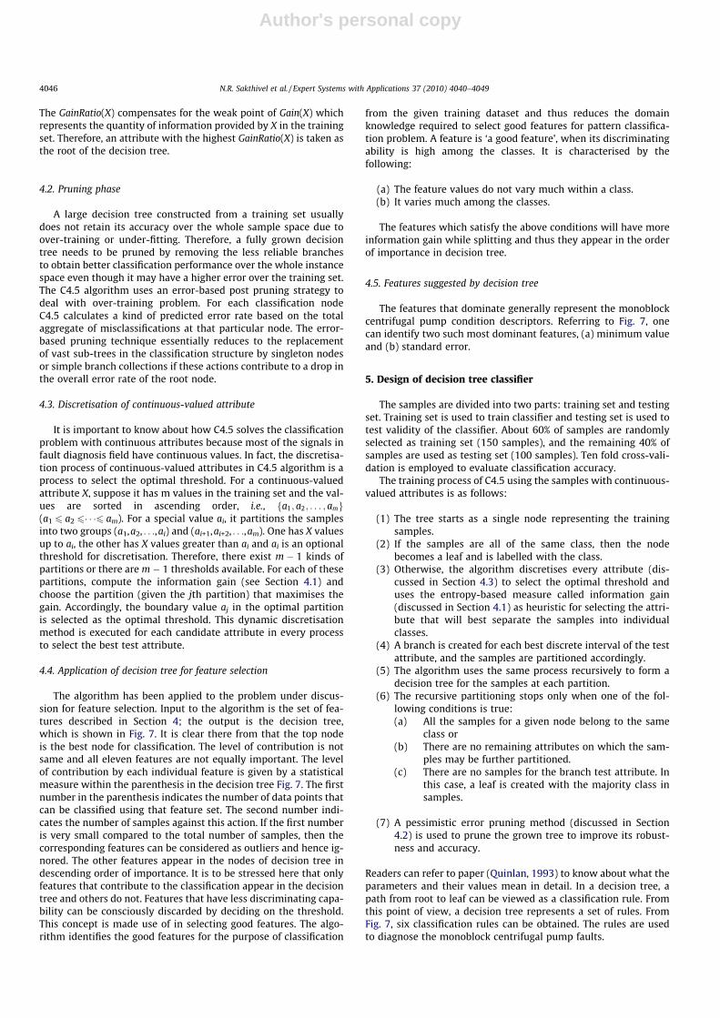
5. The level of contribution by each individual parameter is givenby a statistical measure within the parenthesis in the decisiontree (Fig. 7). The first number in the parenthesis indicates thenumber of data points that can be classified using that param-eter set. The parameters appearing in the nodes of decision treeare in descending order of importance.
6. At each decision node in the decision tree, one can select themost useful parameter for classification using appropriate esti-mation criteria. The criterion used to identify the best parame-ter invokes the concept of entropy and information gaindiscussed in detail in the following subsections. Decision treealgorithm (C4.5) has two phases: building and pruning. Thebuilding phase is also called as the ‘growing phase’.
4.1. Building phase
In the building phase, the training sample set with discrete-val-ued attributes is recursively partitioned until all the records in apartition have the same class. The tree has a single root node forthe entire training set. Then for every partition, a new node is
added to the decision tree. For a set of samples in a partition S, atest attribute X is selected for further partitioning the set intoS1,S2, . . .,SL. New nodes for S1,S2, . . .,SL are created and these areadded to the decision tree as children of the node for S. Also, thenode for S is labelled with test X, and partitions S1,S2, . . .,SL are thenrecursively partitioned. A partition in which all the records haveidentical class label is not partitioned further, and the leaf corre-sponding to it is labelled with the corresponding class. The con-struction of decision tree depends very much on how a testattribute X is selected. C4.5 uses entropy based information gainas the selection criteria. The entropy information gain is calculatedin the following way.
Step 1: Calculate Info(S) to identify the class in the training set S
InfoðSÞ ¼ �Xk
i�1
f½freqðCi; S=jSjÞ�log2½freqðCi; S=jSjÞ�g ð6Þ
where jSj is the number of cases in the training set. Ci is aclass, i = 1,2, . . .,K. K is the number of classes and freq(Ci S)is the number of cases included in Ci.
Step 2: Calculate the expected information value, InfoX(S) for testX to partition S:
InfoXðSÞ ¼ �Xk
i¼1
½ðjSijÞ=jSjInfoðSiÞ� ð7Þ
where L is the number of outputs for test X, Si is a subset ofS corresponding to the ith output and is the number ofcases of subset Si.
Step 3: Calculate the information gain after partition according totest X:
GainðXÞ ¼ InfoðSÞ � InfoXðSÞ ð8Þ
Step 4: Calculate the partition information value SplitInfo(X)acquired for S partitioned into L subsets
SplitInfoðXÞ
¼ �12
XL
i¼1
jSijjSj log2
jSijjSj þ 1� jSij
jSj
� �log2 1� jSij
jSj
� �" #ð9Þ
Step 5: Calculate the gain ratio of Gain(X) over SplitInfo(X):
GainRatioðXÞ ¼ GainðXÞ � SplitInfoðXÞ ð10Þ
Fig. 7. Decision tree.
N.R. Sakthivel et al. / Expert Systems with Applications 37 (2010) 4040–4049 4045
Author's personal copy
The GainRatio(X) compensates for the weak point of Gain(X) whichrepresents the quantity of information provided by X in the trainingset. Therefore, an attribute with the highest GainRatio(X) is taken asthe root of the decision tree.
4.2. Pruning phase
A large decision tree constructed from a training set usuallydoes not retain its accuracy over the whole sample space due toover-training or under-fitting. Therefore, a fully grown decisiontree needs to be pruned by removing the less reliable branchesto obtain better classification performance over the whole instancespace even though it may have a higher error over the training set.The C4.5 algorithm uses an error-based post pruning strategy todeal with over-training problem. For each classification nodeC4.5 calculates a kind of predicted error rate based on the totalaggregate of misclassifications at that particular node. The error-based pruning technique essentially reduces to the replacementof vast sub-trees in the classification structure by singleton nodesor simple branch collections if these actions contribute to a drop inthe overall error rate of the root node.
4.3. Discretisation of continuous-valued attribute
It is important to know about how C4.5 solves the classificationproblem with continuous attributes because most of the signals infault diagnosis field have continuous values. In fact, the discretisa-tion process of continuous-valued attributes in C4.5 algorithm is aprocess to select the optimal threshold. For a continuous-valuedattribute X, suppose it has m values in the training set and the val-ues are sorted in ascending order, i.e., fa1; a2; . . . ; amg(a1 6 a2 6� � �6 am). For a special value ai, it partitions the samplesinto two groups (a1,a2, . . .,ai) and (ai+1,ai+2, . . .,am). One has X valuesup to ai, the other has X values greater than ai and ai is an optionalthreshold for discretisation. Therefore, there exist m � 1 kinds ofpartitions or there are m � 1 thresholds available. For each of thesepartitions, compute the information gain (see Section 4.1) andchoose the partition (given the jth partition) that maximises thegain. Accordingly, the boundary value aj in the optimal partitionis selected as the optimal threshold. This dynamic discretisationmethod is executed for each candidate attribute in every processto select the best test attribute.
4.4. Application of decision tree for feature selection
The algorithm has been applied to the problem under discus-sion for feature selection. Input to the algorithm is the set of fea-tures described in Section 4; the output is the decision tree,which is shown in Fig. 7. It is clear there from that the top nodeis the best node for classification. The level of contribution is notsame and all eleven features are not equally important. The levelof contribution by each individual feature is given by a statisticalmeasure within the parenthesis in the decision tree Fig. 7. The firstnumber in the parenthesis indicates the number of data points thatcan be classified using that feature set. The second number indi-cates the number of samples against this action. If the first numberis very small compared to the total number of samples, then thecorresponding features can be considered as outliers and hence ig-nored. The other features appear in the nodes of decision tree indescending order of importance. It is to be stressed here that onlyfeatures that contribute to the classification appear in the decisiontree and others do not. Features that have less discriminating capa-bility can be consciously discarded by deciding on the threshold.This concept is made use of in selecting good features. The algo-rithm identifies the good features for the purpose of classification
from the given training dataset and thus reduces the domainknowledge required to select good features for pattern classifica-tion problem. A feature is ‘a good feature’, when its discriminatingability is high among the classes. It is characterised by thefollowing:
(a) The feature values do not vary much within a class.(b) It varies much among the classes.
The features which satisfy the above conditions will have moreinformation gain while splitting and thus they appear in the orderof importance in decision tree.
4.5. Features suggested by decision tree
The features that dominate generally represent the monoblockcentrifugal pump condition descriptors. Referring to Fig. 7, onecan identify two such most dominant features, (a) minimum valueand (b) standard error.
5. Design of decision tree classifier
The samples are divided into two parts: training set and testingset. Training set is used to train classifier and testing set is used totest validity of the classifier. About 60% of samples are randomlyselected as training set (150 samples), and the remaining 40% ofsamples are used as testing set (100 samples). Ten fold cross-vali-dation is employed to evaluate classification accuracy.
The training process of C4.5 using the samples with continuous-valued attributes is as follows:
(1) The tree starts as a single node representing the trainingsamples.
(2) If the samples are all of the same class, then the nodebecomes a leaf and is labelled with the class.
(3) Otherwise, the algorithm discretises every attribute (dis-cussed in Section 4.3) to select the optimal threshold anduses the entropy-based measure called information gain(discussed in Section 4.1) as heuristic for selecting the attri-bute that will best separate the samples into individualclasses.
(4) A branch is created for each best discrete interval of the testattribute, and the samples are partitioned accordingly.
(5) The algorithm uses the same process recursively to form adecision tree for the samples at each partition.
(6) The recursive partitioning stops only when one of the fol-lowing conditions is true:(a) All the samples for a given node belong to the same
class or(b) There are no remaining attributes on which the sam-
ples may be further partitioned.(c) There are no samples for the branch test attribute. In
this case, a leaf is created with the majority class insamples.
(7) A pessimistic error pruning method (discussed in Section4.2) is used to prune the grown tree to improve its robust-ness and accuracy.
Readers can refer to paper (Quinlan, 1993) to know about what theparameters and their values mean in detail. In a decision tree, apath from root to leaf can be viewed as a classification rule. Fromthis point of view, a decision tree represents a set of rules. FromFig. 7, six classification rules can be obtained. The rules are usedto diagnose the monoblock centrifugal pump faults.
4046 N.R. Sakthivel et al. / Expert Systems with Applications 37 (2010) 4040–4049

Author's personal copy
6. Results and discussion
The experimental studies have been carried out for good condi-tion and various fault conditions of the pump as discussed in Sec-tion 2. The characteristics curves of the pump are drawn in Figs. 8–10. The discharge vs. efficiency is shown in Fig. 8 for good as well asfaulty conditions. From the figure one can observe that the effi-ciency of the pump is high for good condition and for all faulty con-ditions it falls in a band of values which is far below the goodcondition. It is evident that the efficiency of the pump sharply fallswhen any of the faults that is considered in the study is present inthe pump. Hence this fault diagnosis study is critical to be carriedout. Fig. 9 shows the discharge vs. total head. For good conditionthe head delivered by the pump is high and for all other faulty con-ditions it is far below the good condition. Among the faulty condi-tions, for cavitation the head is reasonably good and for impellerfault head drops drastically compare to other faults. For the otherfaults such as bearing fault, impeller fault and seal fault the headfalls between these two ranges. The head any way is affected bythe faults produced in the present study. The discharge vs. inputpower is shown in Fig. 10. Here it is interesting to note that someof the faulty conditions like impeller fault take a little lower powerinput than that of good condition and other faulty conditions.
It may be misleading to observe only this particular graph as anindividual graph. One should appreciate that the input power ta-ken by the pump alone is not the criteria for the pump perfor-mance. The head delivered by the pump and efficiency of thepump are the most important characteristic measures which de-pend on the condition of the pump. Taking that into consideration,the graph shown in Fig. 9, should be read only in that context.Impeller fault draws a little lower input power is an observation.It does not mean, for reducing pump input, impeller fault can becreated in it. For all other conditions, input power requirement fallmore or less in the same band for various discharges. From Figs. 8–10, the point that is to be understood is, for all faults considered inthe study the performance of the pump is adversely affected whenthe fault is present. Hence, the study is important with these faults.
In the present study C4.5 decision tree algorithm was used asexplained in Section 4. The input of the decision tree is set of sta-tistical features which are extracted from the vibration signals asexplained in Section 3. The output of the decision tree is a decision
tree as shown in Fig. 7. Fig. 7 shows the prominent features that areimportant for the pump fault diagnosis. Here one can observe thatthere are only two features are required to classify the pump con-ditions namely, standard error and minimum value. With the veryfew branches the decision tree algorithm is able to effectively clas-sify the pump conditions. At this stage, the features selection wasdone with 11 statistical features and the useful features are shownin Fig. 7. From the selected features the classification has been car-ried out. To design the classifier (C 4.5) for better classification, ithas to satisfy two contradicting objectives. During training process,the algorithm should not overfit the data. Overfitting seems to givebetter classification results for training dataset; however suchalgorithm tends to give lower classification accuracies for testdataset (unseen samples). If the parameters are adjusted to avoidoverfitting, the algorithm results in lower prediction accuracy. Inorder to have higher prediction accuracy and to avoid overfittingof data, a set of experiments were carried out to design the classi-fier and the results are discussed below.
Fig. 11 shows the minimum number of objects that are requiredto form a class vs. classification accuracy. In this experiment, theminimum number of objects required to form a class was variedfrom 1 to 150 with a step of five and the corresponding classifica-tion accuracies were observed and plotted in Fig. 11. From Fig. 11one can observe that when the minimum number of objects re-quired to form a class is 134 or 135, the classification accuracy ishigh close to 99.66%. Hence it is logical to choose either 134 or135; however when the minimum number of object is small thetree is tend to grow faster leading to more branching activity. Morebranching may lead to higher classification accuracy, but it maytend to over fit the data. For the given situation it is preferable tohave less no of branches and have good classification accuracy.For that the minimum number of objects required to form a classshould be high so that the branching is minimum. This process iscalled pruning as explained in Section 4; keeping this in mind,the minimum number of object chosen in the study was 135. Theother parameter that generally adjusted in the design of C4.5 deci-sion tree algorithm is confidence factor whose values vary from 0to 1. A set of experiment carried out with varying confidence factorvarying from 0 to 1 with a step of 0.05 and with the selected fea-tures keeping the minimum number of object as 135 and the clas-sification accuracy were observed and the plot of the same is
0 0.001 0.002 0.003 0.004 0.005 0.006 0.007 0.008 0.009 0.010
5
10
15
20
25
30
35
40
45
50
Discharge (cubic meter/second)
Eff
icie
ncy
(%)
CavitationImpeller faultSeal faultGoodBearing fault
Fig. 8. Discharge vs. % efficiency.
N.R. Sakthivel et al. / Expert Systems with Applications 37 (2010) 4040–4049 4047

Author's personal copy
shown in Fig. 12. It is evident that the classification accuracy is notsensitive to confidence factor. It means that whatever is the confi-dence factor the classification accuracy remains same. The defaultvalue (0.25) was chosen and with that value the classification wascarried out. With those two parameter tuned, the model obtainedwas trained model which can be used for classification.
The misclassification details are generally presented in the formof a confusion matrix. Confusion matrix for training dataset asshown in Fig. 13. The general procedure for reading and under-standing the confusion matrix is as follows. It looks in the formof a square matrix. Referring to Fig. 13, the first row representsthe total no of data points corresponding to good condition. Thefirst column represents out of that first row elements how manyis correctly classified as good elements. The total in the first rowis 150 out of that 149 is correctly classified and one is misclassifiedas cavitation condition. Similarly in the first row the other ele-ments are zero that means none of those good conditions are mis-classified as other fault conditions. The second row represents thetotal number of data points corresponding to cavitation condition;out of that the first column represents misclassification of those
data points as good condition. In this case one data point is mis-classified as good condition. Second row second column represents
0 0.001 0.002 0.003 0.004 0.005 0.006 0.007 0.008 0.009 0.011
1.5
2
2.5
Discharge (cubic meter/second)
Inpu
t po
wer
(K
ilo W
atts
)
CavitationImpeller faultSeal faultGoodBearing fault
Fig. 10. Discharge vs. input power.
0 50 100 15065
70
75
80
85
90
95
100
Minimum number of objects
Cla
ssif
icat
ion
accu
racy
(%
)
Fig. 11. Minimum number of objects vs. classification accuracy.
0 0.001 0.002 0.003 0.004 0.005 0.006 0.007 0.008 0.009 0.012
4
6
8
10
12
14
16
18
20
Discharge (Cubic meter / Second)
Hea
d (
met
er )
GoodImpeller FaultCavitationSeal FaultBearing Fault
Fig. 9. Discharge vs. total head.
4048 N.R. Sakthivel et al. / Expert Systems with Applications 37 (2010) 4040–4049

Author's personal copy
how many of cavitation data points have been correctly classifiedas cavitation data points. In this case out of 150 data points 148are correctly classified and one is misclassified as seal defect. Itmeans none of those cavitation conditions are misclassified asthe other fault conditions and so on.
Now 100 data points which were kept aside for testing purpose,the classification was carried out using trained classifier. The con-fusion matrix for test dataset as shown in Fig. 14.
In the test dataset the classification accuracy was found to be100%. The results obtained are specific to this particular dataset.Classification accuracy of 100% does not assure similar perfor-mance for all feature datasets. However one can expect classifica-tion accuracy close to 100%. In general the classification accuracy isvery high. Hence this is very much suited for any practicalapplications.
7. Conclusion
This paper deals with vibration based fault diagnosis of mono-block centrifugal pump. Six classical states viz., normal, bearingfault, impeller fault, seal fault, impeller and bearing fault together,cavitation are simulated on mono-block monoblock centrifugalpump. Set of features have been extracted and classified usingC4.5 decision tree algorithm. From the results and discussion asdiscussed above one can confidently say that C4.5 algorithm aswell as the vibration signals are good candidates for practicalapplications of fault diagnosis of monoblock centrifugal pump.
References
Alfayez, L., Mba, D., & Dyson, G. (2005). The application of acoustic emission fordetecting incipient cavitation and the best efficiency point of a 60 kW monoblock centrifugal pump. NDT&E International, 38, 354–358.
Cempel, C. (1988). Vibroacoustical diagnostics of machinery – An outline.Mechanical Systems and Signal Processing, 2, 135–151.
Chen, C., & Mo, C. (2004). A method for intelligent fault diagnosis of rotatingmachinery. Digital Signal Processing, 14, 203–217.
Kong, F., & Chen, R. (2004). A combined method for triplex pump fault diagnosisbased on wavelet transform, fuzzy logic and neural-networks. MechanicalSystems and Signal Processing, 18, 161–168.
Koo, I. S., & Kim, W. W. (2000). The development of reactor coolant pump vibrationmonitoring and a diagnostic system in the nuclear power plant. ISA Transactions,39, 309–316.
McFadden, P. D., & Smith, J. D. (1984). Vibration monitoring of rolling elementbearings by high frequency resonance technique-a review. TribologyInternational, 17, 3–10.
Peck, J. P., & Burrows, J. (1994). On-line condition monitoring of rotating equipmentusing neural networks. ISA Transactions, 33, 159–164.
Polat, K., & Günes, S. (2009). A novel hybrid intelligent method based on C4. 5decision tree classifier and one-against-all approach for multi-classclassification problems. Expert Systems with Applications, 36, 1587–1592.
Quinlan, J. R. (1993). C4.5: Programs for machine learning. San Mateo, CA: MorganKaufmann.
Quinlan, J. R. (1996). Improved use of continuous attributes in C4.5. Journal ofArtificial Research, 4, 77–90.
Rajakarunakaran, S., Venkumar, P., Devaraj, D., & Surya Prakasa Rao, K. (2008).Artificial neural network approach for fault detection in rotary system. AppliedSoft Computing, 8, 740–778.
Sanz, J., Perera, R., & Huerta, C. (2007). Fault diagnosis of rotating machinery basedon auto associative neural networks and wavelet transforms. Journal of Soundand Vibration, 302, 981–999.
Sugumaran, V., Muralidharan, V., & Ramachandran, K. I. (2007). Feature selectionusing decision tree and classification through proximal support vector machinefor fault diagnostics of roller bearing. Mechanical Systems and Signal Processing,21, 930–942.
Sugumaran, V., & Ramachandran, K. I. (2007). Automatic rule learning usingdecision tree for fuzzy classifier in fault diagnosis of roller bearing. MechanicalSystems and Signal Processing, 21, 2237–2247.
Sun, W., Chen, J., & Li, J. (2007). Decision tree and PCA-based fault of rotatingmachinery. Mechanical Systems and Signal Processing, 21, 1300–1317.
Tran, V. T., Yang, B.-S., Oh, M.-S., & Tan, A. C. C. (2009). Fault diagnosis of inductionmotor based on decision trees and adaptive neuro-fuzzy inference. ExpertSystems with Applications, 36, 1840–1849.
Wang, H., & Chen, P. (2007). Sequential condition diagnosis for centrifugal pumpsystem using fuzzy neural network. Neural Information Processing – Letters andReviews, 11(3), 41–50.
Wang, J., & Hu, H. (2006). Vibration-based fault diagnosis of pump using fuzzytechnique. Measurement, 39, 176–185.
Witten, I. H., & Frank, E. (2005). Data mining: Practical machine learning tools andtechniques (2nd ed.). San Francisco: Morgan Kaufmann.
Xiang, X., Zhou, J., An, X., Peng, B., & Yang, J. (2008). Fault diagnosis based on Walshtransform and support vector machine. Mechanical Systems and SignalProcessing, 22, 1685–1693.
Yuan, S.-F., & Chu, F.-L. (2006). Support vector machines-based fault diagnosis forturbo-pump rotor. Mechanical Systems and Signal Processing, 20, 939–952.
Yuan, S.-F., & Chu, F.-L. (2007). Fault diagnostics based on particle swarmoptimization and support vector machines. Mechanical Systems and SignalProcessing, 21, 1787–1798.
Zhang, S., Asakura, T., Xu, X., & Xu, B. (2003). Fault diagnosis system for rotarymachine based on fuzzy neural networks. JSME International Journal, 46,1035–1041.
Zhang, L., Jack, L. B., & Nandi, A. K. (2005). Fault detection using geneticprogramming. Mechanical Systems and Signal Processing, 19, 271–289.
0 0.2 0.4 0.6 0.8 198.5
99
99.5
100
Confidence factor
Cla
ssif
icat
ion
accu
racy
(%
)
Fig. 12. Confidence factor vs. classification accuracy.
Fig. 13. Confusion matrix of tenfold cross-validation (training dataset).
Fig. 14. Confusion matrix (test dataset).
N.R. Sakthivel et al. / Expert Systems with Applications 37 (2010) 4040–4049 4049
Copyright © 2022 FDOKUMEN