Application of hydrodynamic cavitation to wastewater treatment
24
Please do not remove this page Application of hydrodynamic cavitation to wastewater treatment Tao, Yuequn; Cai, Jun; Liu, Bin; et.al. https://scholarship.libraries.rutgers.edu/discovery/delivery/01RUT_INST:ResearchRepository/12643398000004646?l#13643492290004646 Tao, Cai, J., Liu, B., Huai, X., & Guo, Z. (2016). Application of hydrodynamic cavitation to wastewater treatment. In Chemical Engineering & Technology (Vol. 39, Issue 8, pp. 1363–1376). Rutgers University. https://doi.org/10.7282/T3X06982 Downloaded On 2022/07/24 15:37:40 -0400 This work is protected by copyright. You are free to use this resource, with proper attribution, for research and educational purposes. Other uses, such as reproduction or publication, may require the permission of the copyright holder.
-
Upload
khangminh22 -
Category
Documents
-
view
0 -
download
0
Transcript of Application of hydrodynamic cavitation to wastewater treatment

Please do not remove this page
Application of hydrodynamic cavitation towastewater treatmentTao, Yuequn; Cai, Jun; Liu, Bin; et.al.https://scholarship.libraries.rutgers.edu/discovery/delivery/01RUT_INST:ResearchRepository/12643398000004646?l#13643492290004646
Tao, Cai, J., Liu, B., Huai, X., & Guo, Z. (2016). Application of hydrodynamic cavitation to wastewatertreatment. In Chemical Engineering & Technology (Vol. 39, Issue 8, pp. 1363–1376). Rutgers University.https://doi.org/10.7282/T3X06982
Downloaded On 2022/07/24 15:37:40 -0400
This work is protected by copyright. You are free to use this resource, with proper attribution, forresearch and educational purposes. Other uses, such as reproduction or publication, may require thepermission of the copyright holder.

Chem. Eng. Technol. 2016, 39, No. 8, 1363–1376 DOI:10.1002/ceat.201500362
Hydrodynamic cavitation in wastewater treatment: A review Yuequn Tao1, 2, Jun Cai1,
∗, Bin Liu1, 2, Xiulan Huai1,*, Zhixiong Guo3,*
1Institute of Engineering Thermophysics, Chinese Academy of Sciences, Beijing 100190, China 2University of Chinese Academy of Sciences, Beijing 100080, China
3Department of Mechanical and Aerospace Engineering, Rutgers, the State University of New Jersey, 28Piscataway, NJ, USA 29
Abstract 30
Hydrodynamic cavitation has shown considerable application promise in wastewater treatment due to its 31
simple reactor design, convenient operation,high energy efficiency and easy scalization. In this paper, 32
different aspects of hydrodynamic cavitation used for wastewater treatment have been reviewed. 33
Theoretical studies, including the basic mechanism of pollutant degradation, the modeling of pressure 34
distribution in cavitation reactor and the bubble dynamics models coupled with chemical reactions, are 35
evaluated. Experimental setups of various design of reactors and operation parameters are compared 36
under the desired conditions for degrading specific kinds of pollutants in wastewater. In addition to 37
hydrodynamic cavitation, some synergetic approaches are also reviewed. The effort directions for both 38
theoretical and experimental investigations have been provided based on this review. 39
Keywords: Wastewater treatment; Degradation reaction; Chemical effect; Hydrodynamic cavitation; 40
Ultrasonic cavitation. 41
1. Introduction 42
Water pollution in China has become a major problem due to large amounts of domestic sewage and 43
industrial effluent discharged into the water body. Liquid waste coming from industries like textile, 44
pharmacy, pesticide and petrochemical processing contains large amounts of organic compounds such as 45
textile dyes, aromatic compounds, chlorinated hydrocarbons and phenolic compounds. These compounds 46
are bio-refractory or toxic to the microorganisms; and thus, conventional biochemical processes are not 47
able to completely degrade them.1, 2 In the past decade, many researchers have tried different methods for 48
the degradation of organic pollutants,3-7 among which a new technology called as hydrodynamic 49
cavitation has drawn extensive attentions. This technique is not only energy efficient, but also easy to 50
realize scale-up application.8-10 51
Hydrodynamic cavitation occurs when liquid passes through a constriction structure such as a 52
throttling valve, orifice plate, venturi, etc.11, 12 At the constriction region, the velocity of the fluid 53
increases at the expense of a pressure loss. If the pressure falls below the vapor pressure corresponding to 54 ∗ Corresponding author. E-mail address: [email protected] (J. Cai), [email protected](X. L. Huai), [email protected] (Z. Guo).
UnknownField Code ChangedUnknownField Code ChangedUnknownField Code Changed

Chem. Eng. Technol. 2016, 39, No. 8, 1363–1376 DOI:10.1002/ceat.201500362
the liquid temperature, a large amount of cavities will be generated. At the downstream of the constriction, 55
the pressure is subjected to a recovery because of the area enlargement. Subsequently, it leads to collapse 56
of cavity, generating extreme conditions and highly reactive free radicals in the water system, which will 57
favor lots of chemical reactions.13-16 Therefore, hydrodynamic cavitation has been looked upon as an 58
effective means to destruct contaminants in wastewater. 59
In this review, different aspects of hydrodynamic cavitation applied to the treatment of wastewater 60
are addressed. Focus is on the theoretical development and experimental setup comparison. Most 61
important contributions are incorporated, and their advantages and disadvantages are briefed. Some useful 62
recommendations and effort directions for future studied to enable efficient large-scale operations are 63
provided in the conclusion. 64
65
2. Theoretical development 66
2.1 The degradation mechanism 67
It is well known that cavitation is a pressure-related process. At the downstream of a constriction 68
cavitation bubbles expand in volume and experience a violent collapse process as the pressure in the bulk 69
liquid recovers. The degradation of contaminants is usually interpreted as the physical and chemical 70
effects induced by the bubble collapse. There have been a number of illustrations in the literatures, 71
dealing with the mechanism of cavitation induced chemical transformations.17-22 These studies have 72
shown that wastewater treatment due to cavitation should be attributed to the mechanical (e.g., generation 73
of turbulence, liquid jet and shear stress), chemical (e.g., generation of free radicals) and thermaleffects 74
(e.g., generation of local high-temperature hot spots). These effects can lead to the breakdown of 75
chemical bonds, or result in liquid-phase combustion, high temperature decomposition, and organics 76
pyrolyzation in the form of gas phase inside the cavitation bubble. Moreover, vapor molecules trapped 77
inside the bubble will dissociate, giving rise to free radicals.23These free radicals will take part in the 78
oxidation reactions at the bubble-liquid interface or in the bulk liquid.24 Karamah et al.25 evaluated the 79
chemical, mechanical and thermal effects of cavitation by using radical scavengers to suppress radical 80
formation, and claimed that the chemical effect is more significant than the mechanical and thermal 81
effects. 82
The specific degradation process is affected by the properties of pollutants in the effluent stream. For 83
example, rhodamine B may be destructed by hydroxyl radicals at the bubble interfaces or within the bulk 84
solution because of the low vapor pressure of the compound.26 With the effect of hydroxyl radicals, 85
poly-aromatic rings are first separated from the chromophore at the initial stage and then they are 86
degraded, making the complete destruction of the rhodamine B.7, 27 The degradation of Red K-2B is 87
mainly due to the cleavage of the conjugate structures in the molecular, and the aromatic groups are just 88
UnknownField Code ChangedUnknownField Code ChangedUnknownField Code Changed

Chem. Eng. Technol. 2016, 39, No. 8, 1363–1376 DOI:10.1002/ceat.201500362
destroyed partly.28 While for degradation of chitosan solution, there is no obvious modification of 89
chemical structure of degraded chitosan, and the reaction only makes the cleavage of ( )1,4β − 90
glycosidic linkages.29 91
It should be noted that the total amount of degradation depends on the cavitation intensity and the 92
number of cavitation events. Two important parameters known as cavitation number Cv13, 30 and 93
cavitation event rate J 31 have been introduced to characterize these two aspects, and given by, 94
0
20
12
vv
P PC
vρ
−= (2.1) 95
and 96 [ ]0 expJ J Gb= − (2.2) 97
Where P0 is the fully recovered pressure at downstream, Pv is the saturated vapor pressure of the liquid, v0 98
is the velocity of the liquid at the constriction position, J0 is the normalized pre-exponential and Gb 99
denotes the normalized Gibbs activation energy. 100
2.2 The pressure 101
Adequate quantification of the pressure and velocity distributions in cavitation reactors is critical to 102
quantitatively analyze the free radicals generation and pollutant degradation. Among all the approaches 103
reported in the literature, the liner pressure recovery approach is the simplest, but is especially adequate to 104
a geometry generating relatively low turbulence intensity, e.g., a venturi-type constriction with smooth 105
variation of cross-sectional flow area. Yan et al.32 used this approach to consider the behavior of a single 106
bubble in the orifice plate cavitation reactor, in which the pressure recovery profile along the flow 107
direction is approximated by a linear expression being dependent on the distance away from the 108
constriction position. Through time and space conversion33, the local pressure at any position downstream 109
is expressed as: 110
0 vvP PP P tτ−
= + (2.3) 111
where P is the axial pressure at downstream of the orifice, P2 is the fully recovered pressure downstream, 112
t is the moment corresponding to the geometrical positions and τ is the total time for the pressure recovery. 113
The typical radius history of the cavitation bubble obtained by Yan et al.32 indicates that the bubble just 114
oscillates smoothly (the bubble does not collapse violently) and produces pressure pulses with very small 115
magnitudes. However, such low-magnitude pressure pulses are unlikely to bring about the observed 116
chemical effects. Thus, this approach certainly loses its validity in modeling hydrodynamic cavitation 117
flow field with chemical reactions.34 118
Later Moholkar and Pandit30 proposed a more realistic approach by incorporating the turbulent 119
UnknownField Code Changed
UnknownField Code Changed
UnknownField Code Changed

Chem. Eng. Technol. 2016, 39, No. 8, 1363–1376 DOI:10.1002/ceat.201500362
fluctuation effect. In comparison with the non-turbulent conditions, the bubble has larger growth rate as 120
well as higher magnitude of collapse pressure pulses. The flow turbulence transforms the stable cavitation 121
in non-turbulent model into an unstable transient state, and the variation of turbulence frequency affects 122
the cavity in a manner similar to acoustic cavitation. Many researchers have adopted this analogous 123
turbulence model. Cai et al.35, 36 used the turbulence model to investigate the bubble behavior and the 124
resultant temperature evolution inside the bubble for an orifice plate reactor. They found that, by 125
considering the effect of turbulence, both collapse pressure and temperature increase. Gogate and Pandit 12637 used the turbulence model to determine the magnitude of pressure pulse during the bubble collapse in 127
an orifice flow, and also found a significant increase in the magnitudes of pressure pulses compared to 128
Yan et al.’s non-turbulent results. Kumar and Moholkar38 also introduced the oscillatory turbulent 129
components in their simulation. Although their results didn’t show much larger growth rate in the bubble 130
radius, the higher peaks of temperature and pressure at the collapse moment were observed. These 131
phenomena occur due to the more violent collapses of cavities caused by the turbulence action. 132
Nevertheless, it should be noted that, the pressure profile is supposed to consist of two parts in Moholkar 133
and Pandit’s model, i.e., linear recovery pressure and turbulent fluctuating pressure. Therefore, the 134
pressure profile is still not the real distribution in a cavitation reactor. With the development of 135
computational fluid dynamics (CFD) technology, it is possible to obtain more realistic pressure 136
distribution in the reactors. The key is how to consider the discrete CFD simulation results into 137
calculation when solving the bubble dynamics equation. 138
2.3 Bubble dynamics models coupled with chemical reactions 139
For practical application, people are more interested in the chemical effects induced by 140
hydrodynamic cavitation. Various models have been proposed to discuss the link between bubble 141
dynamics (especially under extreme conditions and associated with the collapse) and the formation of free 142
radicals. In the literature, a single isolated spherical bubble model which ignores the bubble/bubble and 143
bubble/flow interactions has been commonly used as basis. The investigation conducted by Storey and 144
Szeri 23, 39 was a landmark work and paved the way for the related studies. By considering mass transfer, 145
vapor condensation and evaporation, and chemical reactions, they presented a general method fully 146
solving the partial differential equations (PDE) for gas dynamics. 147
Without a doubt, the most precise treatment method is the full-depth numerical simulation, but the 148
calculation process is very complicated to solve these PDEs 40. Compared to the full simulation, Toegel et 149
al.41 developed a relatively simple diffusion-limited model, which only includes ordinary differential 150
equations (ODEs). In this model, the radial motion of the bubble as well as the heat and mass change due 151
to evaporation and condensation are solved based on boundary layer approximation. According to 152
boundary layer approximation, the region inside the bubble could be divided into two sections, i.e., a core 153
UnknownField Code ChangedUnknownField Code ChangedUnknownField Code Changed

Chem. Eng. Technol. 2016, 39, No. 8, 1363–1376 DOI:10.1002/ceat.201500362
with a boundary layer. The spatial distribution of species concentration is uniform in the core region, but 154
changes sharply inside the boundary layer near the bubble-liquid interface. The boundary layer thickness 155
for heat and mass transfer is calculated throughout the lifetime of cavity, and both the two regions are 156
treated separately. This kind of approach reduces the mathematical difficulties, but still preserves much of 157
the accuracy. Most of the later theoretical studies were based on this diffusion-limited model. A brief 158
overview about these studies is summarized in Table 1. 159
Table 1 Bubble dynamics models considering chemical reactions 160Researchers Important features of the models
Mauro Capocelli et al.42 Simulations of single bubble dynamic (SBD) with chemical reactions were conducted. The radical production rate that varies with initial bubble size was obtained.
Peeush Kumar 43 In addition to incorporation of heat transfer and solvent vapor transport across bubble during radial motion, this cavitation model also considered the bubble/flow and bubble/bubble interactions. Flow regime maps were represented according to the combinations of design and process parameters.
Mauro Capocelli 44 Global oxidant production was predicted by integrating the estimated radical production over a typical bubble size distribution.
Peeush Kumar and V. S. Moholkar 38 The diffusion-limited model of cavitation bubble dynamics was coupled to hydrodynamic characteristics of the flow through an orifice.
Sudib K. Mishra et al. 45 A model based on the multiphase Lattice Boltzmann Method (LBM) considering inhomogeneous concentrations of the solute was presented.
Amit Sharma et al. 46 An empirical correlation for predicting the pressure was established as a function of operating parameters. Weber number criterion for the stability of the growing bubble was used.
J. Sangeeth Krishnan et al. 47 Both the bubble dynamics model and the associated heat and mass transfer model for the orifice flow were established based on the following approximations: (1) Only turbulent velocity fluctuation along the flow
direction was concerned; (2) Thermodynamic equilibrium was constituted during
the bubble collapse.
It should be noted that the acceptability of a model and its solution schemes strongly depend on the 161
assumptions used in its derivation. Most of the previous investigations were based on the uniform cavity 162
interior model, while Mishra et al. 45 introduced a model based on the multiphase Lattice Boltzmann 163
Method (LBM) that allowed for the couple of reaction kinetics and hydrodynamics in a collapsing cavity. 164
This kind of couple can lead to highly inhomogeneous concentration of solutes, and thus bring the 165

Chem. Eng. Technol. 2016, 39, No. 8, 1363–1376 DOI:10.1002/ceat.201500362
enhancement of concentration-dependent reaction rates and the production of minor species. 166
3. Experimental studies 167
3.1 Typical scheme of the experimental system 168
Among available experimental investigations,10, 48-54 the most common system adopted is shown in 169
Fig.1. 170
171Fig. 1 Typical experimental system 172
The system consists of a closed circulation loop comprising a reservoir, a pump, control valves, a 173
cavitation reactor, and measurement gauges. Water pumped from the reservoir branches into two lines, 174
i.e., a main line where hydrodynamic cavitation takes place and a by-pass line that is used to control the 175
pressure and flow rate. As temperature has a significant effect on the cavitation reaction, a cooling system 176
is provided to control the liquid temperature. 177
3.2 Hydrodynamic cavitation reactors 178
3.2.1 Rotating device 179
When liquid swirls rapidly around the axis of a rotating device in a chamber, the local pressure near 180
the central region will decrease. If it falls below the vapor pressure of the liquid, vortex cavitation55 181
occurs. Subsequently, as water moves towards the bottom surface of the chamber where the pressure 182
raises rapidly, the cavitation bubbles collapse. Wang et al.56, 57 carried out the degradation experiments of 183
rhodamine B and alachlor by using the reactor shown in Fig.2. A pseudo-first order degradation reaction 184
was detected in all experimental cases. The operating conditions such as pressure, temperature, initial 185
UnknownField Code ChangedUnknownField Code ChangedUnknownField Code Changed

Chem. Eng. Technol. 2016, 39, No. 8, 1363–1376 DOI:10.1002/ceat.201500362
concentration of pollutant, pH of water and H2O2 concentration were found to have significant effects on 186
the degradation rate. 187
188Fig. 2 Rotating cavitation reactor 57. 189
Considering that the opposite movement of two shear layers can generate shear cavitation,58 190
Petkovšek59 used a novel rotation cavitation generator to remove pharmaceuticals in water. The generator 191
is based on two facing rotors with special radial grooves spinning in the opposite direction, as shown in 192
Fig. 3. This kind of cavitation generator has advantages of low pressure loss and easy installation. 193
Operating parameters such as rotors geometry, pressure, liquid temperature, hydrogen peroxide yield and 194
exposure time can be optimized to improve the extent of degradation. Based on a rotor and a stator, 195
Badve et al.60-62 reported another kind of cavitation reactor, as shown in Fig.4. For this generator, the 196
rotor is presented in the form of a solid cylinder with indentations on its surface, and cavitation is formed 197
on the surface of the rotor as well as within the indentations due to high speed rotation. After testing the 198
wastewater in papermaking industry, almost 90% COD reduction was observed for this kind of setup. In 199
addition, the rotation speed was also found to be a decisive factor affecting the cavitation activity. 200
201Fig. 3 Cavitation reactor based on two rotors 59 202
Z Guo � 10/28/2016 3:09 PMFormatted: Font:12 pt, Not Bold
Z Guo � 10/28/2016 3:09 PMDeleted:Fig. 3203
Chem. Eng. Technol. 2016, 39, No. 8, 1363–1376 DOI:10.1002/ceat.201500362
204Fig. 4 Cavitation reactor based on a rotor and a stator 60 205
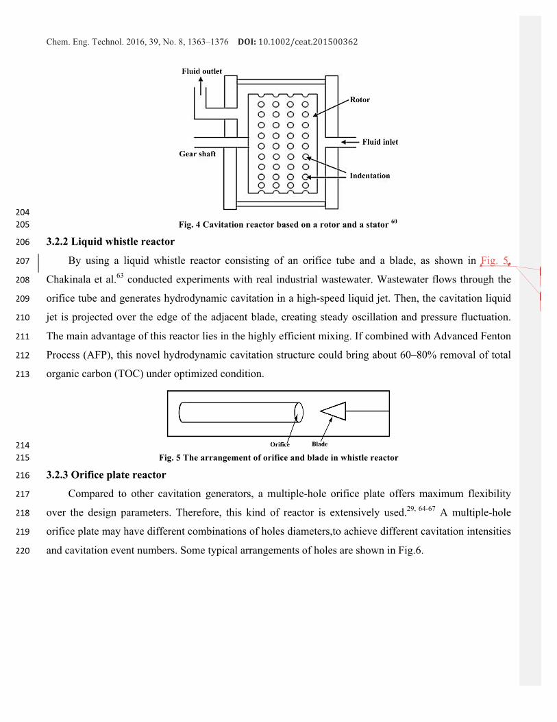
3.2.2 Liquid whistle reactor 206
By using a liquid whistle reactor consisting of an orifice tube and a blade, as shown in Fig. 5, 207
Chakinala et al.63 conducted experiments with real industrial wastewater. Wastewater flows through the 208
orifice tube and generates hydrodynamic cavitation in a high-speed liquid jet. Then, the cavitation liquid 209
jet is projected over the edge of the adjacent blade, creating steady oscillation and pressure fluctuation. 210
The main advantage of this reactor lies in the highly efficient mixing. If combined with Advanced Fenton 211
Process (AFP), this novel hydrodynamic cavitation structure could bring about 60–80% removal of total 212
organic carbon (TOC) under optimized condition. 213
214Fig. 5 The arrangement of orifice and blade in whistle reactor 215
3.2.3 Orifice plate reactor 216
Compared to other cavitation generators, a multiple-hole orifice plate offers maximum flexibility 217
over the design parameters. Therefore, this kind of reactor is extensively used.29, 64-67 A multiple-hole 218
orifice plate may have different combinations of holes diameters,to achieve different cavitation intensities 219
and cavitation event numbers. Some typical arrangements of holes are shown in Fig.6. 220
Z Guo � 10/28/2016 3:09 PMFormatted: Font:12 pt, Not Bold
Z Guo � 10/28/2016 3:09 PMDeleted:Fig. 5221

Chem. Eng. Technol. 2016, 39, No. 8, 1363–1376 DOI:10.1002/ceat.201500362
222Fig. 6 Typical arrangements of orifice plates 223
Two parameters are used to characterize the orifice plate, i.e., α and β, which are given as: 224
2
2
h
h
n ddn
πα
π
×=
⎛ ⎞× ⎜ ⎟⎝ ⎠
(3.1) 225
226
2
h
p
dnd
β⎛ ⎞
= ⎜ ⎟⎜ ⎟⎝ ⎠
(3.2) 227
where n is total number of the holes, dh is the hole diameter and dp is the pipe diameter. It has been 228
qualitatively demonstrated that the degradation rate of pollutant increases with increasing α and 229
decreasing β for a certain flow area. Differences just exist in quantitative aspect,7, 68which is due to 230
different cavitation intensities required for the desired chemical transformations. For example, the 231
cavitation intensity required for the decomposition of rhodamine B is much higher than that of KI 232
decomposition.7 Therefore, varying 𝛼 and 𝛽 will lead to a more obvious change in decomposition. 233
Based on the impingement of cavitation jets induced by orifice plate, Parsa and Zonouzian69 234
creatively used the reactor for rhodamine B degradation, as shown in Fig.7. The reactor contains two 235
orifice plates and two movable flanges supporting orifice plates, which are installed inside the cylindrical 236
vessel. During the experiment, the liquid flows through these two orifice plates from the opposite 237
direction, inducing hydrodynamic cavitation separately. Then, two shares of cavitation jets meet at the 238
center of the vessel and collide with each other, and finally flow out from the outlet port. The 239
experimental results showed that this reactor could bring more than 50% degradation rate for rhodamine 240
B. 241
UnknownField Code ChangedZ Guo � 10/28/2016 3:09 PMFormatted: Do not check spelling orgrammarZ Guo � 10/28/2016 3:09 PMDeleted:1242UnknownField Code Changed

Chem. Eng. Technol. 2016, 39, No. 8, 1363–1376 DOI:10.1002/ceat.201500362
243Fig. 7 Cavitation and jets impingements reactor 69 244
3.2.4 Venturi tube reactor 245
Compared with orifice plate, venturi tube reactor can generate much lower turbulence intensity since 246
the smooth variation of its cross-sectional flow area leads to a much less pressure head loss.70 A typical 247
venturi-type constriction is shown in Fig.8.For a venturi reactor, cavitation intensity is seriously affected 248
by its length and the ratio of throat diameter to pipe diameter. 249
250Fig. 8 A typical venturi tube 251
252Saharan et al.51 conducted the degradation of Reactive Red 120 dye with a transparent venturi 253
reactor. According to their observation, cavitation bubbles formed at the throat and gathered downstream 254
of the throat. Subsequently, these bubbles collapsed when they came out of the venturi tube. The 255
degradation rate was closely linked with the cavitation pattern. When the number density of cavities 256
became high enough, the entire downstream area was filled with cavities. Then, these cavities started 257
coalescing with each other and formed a cavity cloud, which is called choked cavitation.71 Once choked 258
cavitation occurred, the degradation rate started to decrease with increasing inlet pressure. The maximum 259
extent of degradation for the organic pollutant used was up to 84% under optimized condition. 260
3.2.5 Selection of hydrodynamic cavitation reactor 261
Energy efficiency is a major consideration in the selection of cavitation equipment. Cavitation yield, 262
defined as the ratio of the observed cavitation effect to the energy supplied to the system, can be treated 263
as a criterion to assess the energy efficiency. For wastewater treatment application, cavitation effect can 264
be measured with the pollutant removal. The input energy, in the case of ultrasonic cavitation, is the 265
electrical energy consumed by the generator to produce the ultrasonic irradiation. In the case of 266
hydrodynamic cavitation, the input energy is consumed by the pump to circulate the aqueous solution of 267
the pollutant in the cavitation chamber.65 268
Many studies have been conducted to compare the energy efficiencies of hydrodynamic and 269

Chem. Eng. Technol. 2016, 39, No. 8, 1363–1376 DOI:10.1002/ceat.201500362
ultrasonic cavitations for the degradation of organic pollutants.56, 61, 64, 72-74However, the investigations on 270
the comparison of cavitation yield among different hydrodynamic cavitation reactors are not as many. 271
Early efforts made by Moholkar and Pandit 75, 76 to address the effects of several design parameters of two 272
hydrodynamic cavitation reactors, viz., venturi tube and orifice plate, can be treated as a basis for the 273
optimization of hydrodynamic cavitation reactor in a target application. In the case of a venturi tube, the 274
radial motion of the bubble is of stable oscillatory type due to a linear pressure recovery, whereas the 275
bubble motion in the orifice flow is a combination of stable oscillation with transient motion due to an 276
additional oscillating pressure. Besides, the pressure drop of the orifice plate is much higher than that of 277
venture tube, thus cavitation intensity in the orifice plate is of much higher magnitude than that in venturi 278
tube. On this basis, Moholkar and Pandit suggested some important strategies for the design of 279
hydrodynamic cavitation reactor. For more details, see Ref.75 280
Using different cavitation devices, viz. orifice plate, circular venturi and slit venturi, Saharan et 281
al.52 studied the degradation of orange-G dye and discussed the effects of the geometry and operating 282
parameters on degradation rate. The degradation rate of the slit venturi configuration was almost 50% 283
higher than those of the other two structures. They also pointed out that the maximum cavitation yield 284
could only be obtained by considering the effect of all these parameters collectively. 285
It is noteworthy that, since the operating and geometrical parameters of cavitation reactors used in 286
the studies are diverse, it is very difficult to conclusively evaluate the cavitation yield of different 287
cavitation reactors. What’s more, due to the mutual coupling of these parameters, how the hydraulic 288
characteristic of a reactor affects the degradation rate still needs to be further explored. Besides, the 289
physicochemical properties are yet to be determined as the key consideration for the selection of optimum 290
cavitation reactors. 291
3.3 Optimization of operating parameters 292
3.3.1 Effect of inlet pressure 293
There exits an optimum inlet pressure in hydrodynamic cavitation setup due to the combined effects 294
of cavitation intensity and cavitation events number. An increase in the inlet pressure can enhance the 295
cavitation intensity by promoting the fluctuation of turbulent pressure and increasing the final magnitude 296
of the recovered pressure at downstream of the constriction.77 Higher temperature and pressure pulse will 297
be generated in enhanced cavitation intensity. Therefore, more water molecules trapped in the cavity will 298
be dissociated, resulting in higher concentration of hydroxyl radicals and degradation rate. However, a 299
further increase of inlet pressure will make the number density of cavities become so high that these 300
cavities coalesce to form much larger cavitation bubbles, leading to the choked cavitation. These larger 301
bubbles will escape from the liquid without collapse or suffer from incomplete collapse, reducing the 302
degradation rate after the optimum inlet pressure is reached. Some experimental works on the degradation 303

Chem. Eng. Technol. 2016, 39, No. 8, 1363–1376 DOI:10.1002/ceat.201500362
of orange 4 dye using a venturi reactor clearly confirmed this fact. The extent and rate of discoloration 304
were 30.54% and 3.44×10⁻³ min−1 at an inlet pressure of 3 bar, and achieved the maximum 37.23% and 305
4.94×10⁻³ min−1 at 5 bar, but then decreased to 26.85% and 2.58×10⁻³ min−1 at 8 bar78. Similar 306
phenomenon was also observed for the degradation of methyl parathion.79 Also, the degradation of 307
dichlovos using an orifice plate reactor qualitatively showed the same trend.80 The specific optimum 308
value of inlet pressure is significantly dependent on the geometry of the chemical system. 309
3.3.2 Effect of bulk liquid temperature 310
Temperature affects the dynamics of the cavities by means of liquid properties. Bubble dynamics 311
investigations 81revealed that, as the temperature of liquid increases, parameters such as viscosity, surface 312
tension and gas solubility reduce, and thus both the cavitation intensity and the number of cavity nuclei 313
reduce. An increase of temperature also increases the vapor pressure inside the bubble and leads to a 314
cushioning effect, making the bubble collapse less effectively. However, a larger amount of free radicals 315
will also be generated since higher concentrations of chemical species are presented in cavitation bubble 316
with higher temperature. Therefore, the overall effect is sometimes unpredictable.82 The effect of 317
temperature on discoloration of orange acid-II 83 and orange 7 84 showed that low temperature was 318
favorable for enhancing the discoloration. But, the experiment on degradation of 2,4-dinitrophenol 319
showed that the extent of degradation increased with increasing the temperature and then marginally 320
decreased after 35 °C.85 A similar change trend was also observed in the degradation of alachlor.57 The 321
degradation rate increased with temperature rise in the range of 30-40 ℃, and decreased with temperature 322
rise over the range of 40-60 ℃. 323
3.3.3 Effect of pH 324
Usually, acid condition is recommended for pollutant degradation by hydrodynamic cavitation.1, 27, 51, 32577, 78, 86, 87 Acid condition can favor the generation of hydroxyl radicals due to the decomposition of 326
hydrogen peroxide, and impede the recombination reaction among these free radicals. The effect of 327
solution pH on the extent of degradation of diclofenac sodium was investigated by varying initial pH over 328
the range of 4–7.5.It was observed that for a change in pH from 7.5 to 4, the extent of degradation rose 329
from 14.7% to 26.8%.86 Similarly, the degradation experiment of imidacloprid showed that the maximum 330
extent of degradation was obtained at an optimum pH of 3. Under alkaline conditions, the extent of 331
degradation was much lower than that under acidic conditions.87 332
3.3.4 Effect of initial concentration of pollutant 333
On one hand, increasing the initial pollutant concentration will decrease the degradation rate.57 If the 334
cavitation conditions keep unchanged, the amount of HO∙ radicals in the system would be constant, but 335
the total pollutant amount in the solution increases with increasing the initial pollutant concentration. So 336

Chem. Eng. Technol. 2016, 39, No. 8, 1363–1376 DOI:10.1002/ceat.201500362
the degradation rate is reduced. On the other hand, the increase of initial pollutant concentration will 337
make more pollutants captured by HO∙, thereby the total amount of decomposition is increased.88The 338
effect of initial concentration of imidacloprid on the extent of degradation was investigated using the slit 339
venturi cavitation reactor.The pseudo first order rate constant was observed to increase from 0.79×10⁻³ 340
min−1 to 1.27×10⁻³ min−1 with the decreasing initial concentration from 60 ppm to 20 ppm.87Similar 341
results have also been observed by Patil and Gogate,79 Bagal and Gogate,85 and Jawale et al.,89 in the 342
degradation of pollutant using hydrodynamic cavitation as well as ultrasonic cavitation. 343
3.3.5 Effect of initial radius of the nuclei 344
The ratio of the maximum bubble radius to initial bubble radius decreases with an increase in the 345
initial radius.90 Cavities with lower initial size will grow to a larger extent and give more violent collapse. 346
Hence, decreasing the initial radius will promote the pressure pulse caused by the bubble collapse, and 347
enhance the overall effect of hydrodynamic cavitation.37, 91 348
3.3.6 Effect of physical-chemical properties of the liquid 349
According to Refs 33, 71, 81, 92, the favorable conditions for cavitation inception are: low liquid vapor 350
pressure, low viscosity and high surface tension. An increase of the vapor pressure will enhance the vapor 351
content inside the cavity, as a result, the intensity of bubble collapse decreases due to the cushioning 352
effect brought by the continuous condensation of vapor phase in higher pressure. Therefore, liquids with 353
lower vapor pressure will generate higher cavitation intensity. Increasing the viscosity will raise the 354
threshold pressure of cavitation event since it has to overcome stronger natural cohesive forces. Hence, 355
there is a better cavitation effect in lower viscosity fluids. According to Eq.(3.3), the surface tension can 356
affect the critical size of stable nucleus 93. 357
32cGTRσ
= (3.3) 358
where σ is surface tension coefficient, T is liquid temperature, G=3RgM/4π (Rg is gas constant, and M is 359
the molecular mass). The higher the surface tension is, the smaller the nucleus is. Hence, the collapse is 360
more violent, and the final collapse temperature and pressure are marginally higher for those liquids with 361
higher surface tension.Effect of surface tension (2σ/R 94) becomes increasingly important during the 362
collapse as the radius becomes smaller. 363
3.4 Deficiency of the existing experimental investigations 364
Experimental results have proved that hydrodynamic cavitation is able to degrade many organic 365
pollutants such as textile dyes (e.g., rhodamine B, red 88 dye, red 120 dye, orange-G and red K-2BP), 366
aromatic compounds (e.g., toluene, xylene, ethyl-benzene and nitrobenzene), chlorinated hydrocarbons 367
(e.g., chloroform, carbon tetrachloride and trichloroethylene), phenolic compounds (e.g., phenol and 368

Chem. Eng. Technol. 2016, 39, No. 8, 1363–1376 DOI:10.1002/ceat.201500362
dihydroxyhenzene), drugs (e.g., carbamazepine and chitosan), and pesticides (e.g., aniline, 369
parathion-methyl, dichlorvos and alachlor). These experiments were commonly conducted in the 370
laboratory scale with single-component solution. Overall, based on these experimentations, some 371
coherent rules of chemical reaction dynamics and influencing factors have been obtained at least from the 372
qualitative perspective, but there still exist problems in view of quantitative analysis. 373
In terms of cavitation reactors, there is currently a lack of comparison and validation of the results 374
among research groups due to the fact that a multitude of different self-made devices were employed. To 375
solve this problem, standardized devices (consist only of commercially available parts) would be helpful. 376
These standardized cavitation devices with different flow fields, turbulence characteristics and 377
geometrical parameters are required for studying the effects of these factors on cavity dynamics and 378
degradation characteristics. Besides, experiments in different scales should be carried out to understand 379
and address scale-up issues, such as alteration in the flow field and turbulence characteristics. 380
While in terms of properties of pollutant substrates, there are still no clear correlations between the 381
physicochemical parameters (e.g., viscosity, density, surface tension, vapor pressure, solubility in water 382
and Henry’s Law constants) and the degradation conversion. On one hand, the number of substrates in 383
some experiments is probably too small to draw generalized statements. On the other hand, it is of great 384
difficulty to compare data gained from different experiments due to the discrepancy of cavitation devices 385
and operating conditions. What’s more, some recent studies have used synthetically-made effluents (by 386
dissolving a pure pollutant in water) for evaluating the effects of hydrodynamic cavitation. As the actual 387
industrial wastewater often contains variable amounts of other compounds and solvents, however, the 388
results achieved under these conditions may not be reproduced with actual wastewater. 389
4. Hydrodynamic cavitation with intensified strategies. 390
As mentioned above, hydrodynamic cavitation does have application potential in wastewater 391
treatment. However, it is also very difficult to obtain satisfactory treatment efficiency by using 392
hydrodynamic cavitation alone in some experiments. Korniluk and Ozonek 95 investigated the application 393
of hydrodynamic cavitation to landfill leachate treatment. Though the landfill leachate characterized by a 394
high concentration of organic carbon and total nitrogen could be degraded by hydrodynamic cavitation, 395
the degradation efficiency was relatively low. Only 6.7% of COD and 5.1% of TOC were removed after 396
30 min treatment. In order to generate higher quantum of oxidizing agents, the process based on 397
hydrodynamic cavitation could be supplemented by other processes. 398
4.1 Effect of H2O2 addition 399
Hydrogen peroxide and water molecules can be dissociated with the formation of radicals: 400
2H O HO H→ +g g (4.1) 401
UnknownField Code ChangedUnknownField Code ChangedUnknownField Code Changed
UnknownField Code Changed

Chem. Eng. Technol. 2016, 39, No. 8, 1363–1376 DOI:10.1002/ceat.201500362
2 2H O HO HO→ +g g (4.2) 402
2 2 2H O HO H O HO+ → +g g (4.3) 403
In the presence of cavitation, hydrogen peroxide, on one hand, will show a synergetic effect due to 404
the supply of additional hydroxyl radicals. On the other hand, if excessive addition, it can also scavenge 405
the generated hydroxyl radicals. Thus, use of hydrogen peroxide is favored only in optimum 406
concentrations, which is decided by the type of the pollutant as well as cavitation intensity. Wang et al.28, 40788 studied the synergetic effect of swirling jet-induced cavitation and H2O2 on the degradation of 408
rhodamine B and red K-2BP. It was found that the degradation rate increased obviously with the 409
increasing loading of hydrogen peroxide. In the presence of 150 mg/L H2O2, the degradation rate for 410
rhodamine B was 2.78×10⁻²/min, which is much higher than that in case of only hydrodynamic cavitation. 411
There is also synergetic effect between hydrodynamic cavitation and H2O2 for the degradation of K-2BP. 412
The data revealed that the adjunction of 300 mg/L H2O2 made the degradation rate at constant of K-2B 413
increase by almost ten times (from 1.31×10⁻³/min to 1.25×10⁻²/min). But the degradation rate was no 414
longer significantly increased when the addition concentration of H2O2 exceeded 300 mg/L. Similar 415
results were found in the degradation of reactive Red 120 dye and Red 88 Dye by using different molar 416
ratios of dye to H2O2. 1, 51 Compared with only 60% reduction of color and 28% reduction of TOC in case 417
of only hydrodynamic cavitation, when the molar ratio of added H2O2 to dye concentrations was 1:60, 418
almost 100% decolonization and 60% reduction of TOC were obtained after 3 hours operation. It was 419
also observed that there was only 13.15% reduction of color using the same amount of H2O2addition with 420
normal stirring (no hydrodynamic cavitation). On one hand, the addition of H2O2 provides supplementary 421
oxidizing agents. On the other hand, hydrodynamic cavitation enhances the decomposing of H2O2 and 422
also the micro mixing of reactant. Thus, the combination of hydrodynamic cavitation and H2O2 gives a 423
better result as compared to individual operation of these processes. When exceeding this additive 424
concentration, however, there was no further increase in color and TOC reduction. 425
4.2 In combination with Advanced Fenton Process (AFP) 426
Fenton process is another advanced oxidation process, in which highly reactive hydroxyls are 427
produced by the decomposition of hydrogen peroxide with ferrous ion (Fe2+) as catalyst in acidic milieu. 428
Then, reactive hydroxyls can effectively react with the toxic organic pollutants. The exact reaction 429
mechanism leading to enhanced HO∙ radicals generation is given as follows 96, 97: 430
2 3 12 2Fe H O Fe HO OH+ + −+ → + +g (4.4) 431
2 3Fe HO Fe OH+ + −+ → +g (4.5) 432
3 22 2Fe H O Fe OOH H+ + ++ → +g (4.6) 433
2 2Fe OOH Fe HOO+ +→ +g g (4.7) 434
UnknownField Code ChangedUnknownField Code Changed
UnknownField Code ChangedUnknownField Code ChangedUnknownField Code ChangedUnknownField Code Changed

Chem. Eng. Technol. 2016, 39, No. 8, 1363–1376 DOI:10.1002/ceat.201500362
3 22Fe HOO Fe O H+ + ++ → + +g (4.8) 435
To maximize the effectiveness of AFP, the solution pH, ferrous ion concentration, hydrogen 436
peroxide loading and operating temperature should be optimized. By using different additives such as 437
hydrogen peroxide, carbon tetrachloride, and Fenton’s reagent, Joshi and Gogate80 conducted an 438
intensification study of dichlorvos degradation. It was observed that the maximum extent of degradation 439
was achieved by combining hydrodynamic cavitation with Fenton process. Efficiencies of different 440
combinations were investigated at four different ratios of FeSO4: H2O2, viz., 3:1, 2:1, 1:1, 0.5:1. The 441
results indicated that, at the same concentration of H2O2, both the rate constant and the removal increased 442
significantly with an increase in FeSO4 loading. This can be attributed to the generation of higher 443
quantum of free radicals in the presence of higher quantum of Fe2+. The similar trend was reported by 444
Patil and Gogate79 with degradation of methyl parathion using the same device. 445
The initial concentration and pH of the solution play an important role in Fenton process. Pradhan 446
and Gogate77 investigated the removal of p-nitrophenol in 5g/L and 10g/L initial concentrations, 447
respectively. Using hydrodynamic cavitation alone, the removal for 5g/L initial concentration of 448
p-nitrophenol was 53.4% whereas for 10g/L initial concentration it was 44.8% under other same 449
conditions. In combination with AFP, the maximum extent of degradation increased. For 5g/L initial 450
concentration, a maximum removal of 63.2% was obtained at 1g/L FeSO4 and 5g/L H2O2 loadings. While 451
for 10g/L initial concentration, the maximum removal of 56.2% was observed at 1g/L FeSO4 and 7.5 g/L 452
H2O2 loadings. Such a difference is because higher concentration of pollutant requires higher loading of 453
hydrogen peroxide to yield more oxidizing agents for pollutant removal. The maximum removal was 454
obtained at pH=3.75. When the solution was in alkaline condition (pH=8.0), the extent of removal fell 455
considerably because both the form of iron species and their catalytic activities are affected by solution 456
pH. The generation of hydroxyl radicals due to the decomposition of hydroxyl radicals is favored and also 457
the oxidation capacity of hydroxyl radicals is higher under acidic condition. 458
The above-mentioned studies have used synthetically-made effluents to evaluate the efficacy of 459
hydrodynamic cavitation in combination with AFP. Chakinala et al.63 firstly reported the use of this 460
approach for real industrial wastewater treatment. In their study, hydrodynamic cavitation induced by a 461
liquid whistle reactor in conjunction with AFP was used to deal with two kinds of industrial effluent, viz., 462
phenolic compounds and pink dye stuffs. Under optimized conditions depending on the type of effluent 463
samples, 60-70% removal of TOC and 85% removal of COD were obtained. This demonstrates that the 464
combination of hydrodynamic cavitation with AFP is also effective in real industrial wastewater 465
treatment. 466
UnknownField Code Changed

Chem. Eng. Technol. 2016, 39, No. 8, 1363–1376 DOI:10.1002/ceat.201500362
4.3 In combination with acoustic cavitation 467
Compared with acoustic cavitation, hydrodynamic cavitation provides better scale-up possibilities, 82 468
higher bubble number densities, and lower investment cost.98 However, the collapse intensity of bubbles 469
in hydrodynamic cavitation is relatively low.99 Therefore, a combination of both techniques in one reactor 470
system was introduced. Franke et al.100 investigated the degradation of chloroform by using ultrasonic 471
cavitation, hydrodynamic cavitation and their combination. After 30-min treatment, the combination of 472
acoustic cavitation with hydrodynamic cavitation gave the best conversion of 90%, while the conversions 473
were 70% and 7% for individual ultrasonic and hydrodynamic cavitations, respectively. Thus, The 474
conversion in case of the combined method is 13% higher than the sum of conversions for individual 475
method. This demonstrates that both acoustic cavitation and hydrodynamic cavitation can promote each 476
other viz., 1+1>2. Braeutigam et al.101 also found the synergistic effect between hydrodynamic cavitation 477
and acoustic cavitation. The use of individual method, hydrodynamic cavitation or acoustic cavitation, 478
was only able to transform carbamazepine to an extent of 27 % or 33% respectively. However, the 479
combined method could bring a conversion more than 96% (36% higher than the sum of conversions for 480
individual method). Jyoti and Pandit 48 compared the efficiencies of acoustic cavitation, hydrodynamic 481
cavitation, hydrogen peroxide and their combinations for disinfecting total coliforms, fecal coliforms and 482
fecal streptococci. The results showed that, though the cavitation yieldwas not as high as that in the case 483
of individual acoustic cavitation, the extent of killed bacterial was much higher in the case of the 484
combination of hydrodynamic cavitation with acoustic cavitation. A bacterial removal of 99.9% was 485
achieved by combining hydrodynamic cavitation, acoustic cavitation and H2O2. 486
4.4 Patented and commercialized oxidation process involving hydrodynamic cavitation 487
It should be noted that the majority of studies on cavitation disposed wastewater are in laboratory 488
scale and there are only a few examples based on practical utilization of such technique. In the following, 489
two patented cavitation oxidation processes/reactors with commercial viability named CAV-OX and 490
Ozonix will be reviewed. 491
4.4.1 The CAV-OX Process 492
The CAV-OX process was developed by Magnum Water Technology of EI Segundo, California, 493
using the combination of hydrodynamic cavitation, ultraviolet radiation, and hydrogen peroxide to 494
oxidize organic compounds in water.102 A schematic of the process is shown in Fig.9. The CAV-OX 495
process can treat a number of contaminants such as pentachlorophenol, benzene, toluene, ethyl benzene, 496
xylenes, cyanide, phenol, atrazine. A variety of cases studied in pilot plant scale show that the process is 497
highly effective. The synergistic combination of cavitation, UV radiation and hydrogen peroxide can 498
reduce contaminant concentrations by 95% to 99.99% under optimum conditions. 499

Chem. Eng. Technol. 2016, 39, No. 8, 1363–1376 DOI:10.1002/ceat.201500362
500Fig. 9. The CAV-OX process 501
4.4.2 The hybrid advanced oxidation reactor: Ozonix 502
Gogate et al.103 developed a hybrid advanced oxidation reactor using a combination of 503
hydrodynamic cavitation, acoustic cavitation, ozone injection and electrochemical oxidation/precipitation, 504
which is called Ozonix and shown in Fig.10. This chemical free reactor was tested, deployed, and 505
commercialized in USA and the effectiveness was demonstrated in bacteria disinfection over a three-year 506
period. The 776 bacteria tested samples were taken from 282 wells in the Fayetteville Shale. The results 507
showed that the bacteria removal was up to 96.5% for Acid Producing Bacteria (APB) samples and 508
97.5% for sulfate-reducing bacteria (SRB) samples. Meanwhile, this kind of reactor also showed the 509
superiority in increasing the flow ability and chemical compatibility of treated water. 510
511
Fig. 10 Schematic representation of the Ozonix reactor 512
5 Conclusions 513
The present work overviews the theoretical and experimental aspects of hydrodynamic cavitation 514
UnknownField Code ChangedUnknownField Code ChangedUnknownField Code Changed
Chem. Eng. Technol. 2016, 39, No. 8, 1363–1376 DOI:10.1002/ceat.201500362
applied to wastewater treatment. It has been observed that the chemical effect of hydrodynamic cavitation 515
is a dominant mechanism in this application, but mechanical and thermal effects are also important. The 516
geometry of reactors and the operating parameters have important effects on the degradation rate and 517
cavitation yield. Optimization of the operating parameters using theoretical analysis as well as 518
laboratory-scale study is always recommended before putting the new technology into practice. Further 519
theoretical and experimental work to establish pathways for transferring the fundamental technique into 520
practice is suggested as follows. 521
Efforts needed in terms of theoretical study are as follows: 522
(1) Most of the previous investigations dealing with the degradation effect of hydrodynamic 523
cavitation are based on the single spherical bubble assumption, which are not identical to the real 524
situation. Realistic models that take the bubble-bubble\bubble-liquid interface and the non-spherical 525
bubble collapse phenomenon into account are in urgent need. Meanwhile, more accurate pressure 526
distribution should be adopted in new models. 527
(2) Chemical effects of hydrodynamic cavitation in terms of hydroxyl radical generation have been 528
studied massively, yet there is a lack of direct simulation of the degradation process on basis of chemical 529
reaction kinetics. In other words, the existing investigations are insufficient in direct and quantitative 530
descriptions to the free radicals reaction with the contaminants. 531
(3) The effects of geometric and operating parameters on the flow conditions should be studied in 532
detail, and the generalized correlations relating the hydroxyl radical generations with the operating 533
parameters need to be developed for various cavitation reactors. 534
(4) Simulations based on CFD technique, in which the chemical reactions are taken into 535
consideration to analyze the degradation process either in a single bubble or in the cavitation fields, 536
should be carried out. 537
Efforts required on the experimental front are as follows: 538
(1) Standardized devices that consist only of commercially available parts should be used to 539
generate comparable results. The design and fabrication of such devices with different flow fields, 540
turbulence characteristics and geometrical parameters are required for studying the effects of these factors 541
on cavity dynamics and degradation characteristics. 542
(2) More experimental studies are needed in different scales of operation to understand and address 543
scale-up issues, such as alterations in the flow field and the turbulence characteristics due to the scales of 544
operation. 545
(3) The design concerning of reactors for degrading pollutant with the same nature should be 546
presented. Experiments dealing with solutions of multi-components need to be carried out, in which the 547
reaction rate and products should be detected to characterize and optimize the degradation process. The 548
Chem. Eng. Technol. 2016, 39, No. 8, 1363–1376 DOI:10.1002/ceat.201500362
interaction between components should be considered to give reproducible results. 549
(4) A large number of substrates should be employed to evaluate the effect of physicochemical 550
properties on the degradation process. Properties such as vapor pressure, solubility in water, viscosity and 551
density, should be correlated with the conversion. 552
(5) Intensified strategies should be optimized to bring maximum chemical effects of hydrodynamic 553
cavitation. 554
Acknowledgements
This work is financially supported by the National Natural Science Foundation of China (51376181)
and the National Basic Research Program of China (2011CB710705)
References (1) Saharan, V. K.; Pandit, A. B.; Panneerselvam, S.; Anandan, S., Hydrodynamic Cavitation as an Advanced OxidationTechniquefortheDegradationofAcidRed88Dye.Ind.Eng.Chem.Res.2012,51,(4),1981-1989.(2) Rodriguez,S.;Santos,A.;Romero,A.,EffectivenessofAOP'sonabatementofemergingpollutantsandtheiroxidationintermediates:NicotineremovalwithFenton'sReagent.Desalin.WaterTreat.2011,280,(1–3),108-113.(3) Li, K.; Zhang,H.; Tang, Y.; Ying,D.; Xu, Y.;Wang, Y.; Jia, J., Photocatalyticdegradationandelectricity generation in arotatingdiskphotoelectrochemicalcelloverhierarchicalstructuredBiOBrfilm.Appl.Catal.,B2015,164,(0),82-91.(4) Garcia-Segura, S.; Keller, J.; Brillas, E.; Radjenovic, J., Removal of organic contaminants from secondary effluent byanodicoxidationwithaboron-dopeddiamondanodeastertiarytreatment.J.Hazard.Mater.2015,283,(0),551-557.(5) Yak, H. K.; Wenclawiak, B. W.; Cheng, I. F.; Doyle, J. G.; Wai, C. M., Reductive Dechlorination of PolychlorinatedBiphenylsbyZerovalentIroninSubcriticalWater.Environ.Sci.Technol.1999,33,(8),1307-1310.(6) Adewuyi, Y. G., Sonochemistry in Environmental Remediation. 2. Heterogeneous Sonophotocatalytic OxidationProcessesfortheTreatmentofPollutantsinWater.Environ.Sci.Technol.2005,39,(22),8557-8570.(7) Sivakumar, M.; Pandit, A. B., Wastewater treatment: a novel energy efficient hydrodynamic cavitational technique.Ultrason.Sonochem.2002,9,(3),123-131.(8) Gogate, P. R., Cavitation: an auxiliary technique in wastewater treatment schemes. Adv. Environ. Res. 2002, 6, (3),335-358.(9) Gogate, P. R.; Pandit, A. B., A review of imperative technologies forwastewater treatment II: hybridmethods.Adv.Environ.Res.2004,8,(3–4),553-597.(10) Gogate, P. R., Treatment of wastewater streams containing phenolic compounds using hybrid techniques based oncavitation:Areviewofthecurrentstatusandthewayforward.Ultrason.Sonochem.2008,15,(1),1-15.(11) Franc,J.-P.;Michel,J.-M.,Fundamentalsofcavitation.SpringerScience&BusinessMedia:2006;Vol.76.(12) Young,F.R.,Cavitation.WorldScientific:1999.(13) Gogate,P.R.;Pandit,A.B.,Hydrodynamiccavitationreactors:Astateoftheartreview.ReviewsinChemicalEngineering2001,17,(1),1–85.(14) Shah,Y.T.;Pandit,A.B.;Moholkar,V.S.,Cavitationreactionengineering.Springer:1999.(15) Flannigan,D.J.;Suslick,K.S.,Plasmaformationandtemperaturemeasurementduringsingle-bubblecavitation.Nature2005,434,(7029),52-55.(16) Didenko, Y. T.; Suslick, K. S., The energy efficiency of formation of photons, radicals and ions during single-bubblecavitation.Nature2002,418,(6896),394-397.(17) Suslick,K.S.,Sonochemistry.Science1990,247,(4949),1439-1445.(18) Zhang, G. M.; Hua, I., Cavitation Chemistry of Polychlorinated Biphenyls: Decomposition Mechanisms and Rates.Environ.Sci.Technol.2000,34,(8),1529-1534.(19) Gogate, P. R., Cavitational reactors for process intensification of chemical processing applications: A critical review.Chem.Eng.Process.2008,47,(4),515-527.(20) Suslick,K.S.;Didenko,Y.;Fang,M.M.;Hyeon,T.;Kolbeck,K.J.;McNamara,W.B.;Mdleleni,M.M.;Wong,M.,Acousticcavitationanditschemicalconsequences.Philos.Trans.R.Soc.London,Ser.A1999,357,(1751),335-353.(21) Xiao,R.;Wei,Z.;Chen,D.;Weavers,L.K.,KineticsandMechanismofSonochemicalDegradationofPharmaceuticalsinMunicipalWastewater.Environ.Sci.Technol.2014,48,(16),9675-9683.(22) Zhang,G.;Hua, I.,CavitationChemistryofPolychlorinatedBiphenyls: DecompositionMechanismsandRates.Environ.

Chem. Eng. Technol. 2016, 39, No. 8, 1363–1376 DOI:10.1002/ceat.201500362
Sci.Technol.2000,34,(8),1529-1534.(23) Storey, B. D.; Szeri, A. J.,Water vapour, sonoluminescence and sonochemistry. Proc. R. Soc. A-Math. Phys. Eng. Sci.2000,456,(1999),1685-1709.(24) Yasui,K.;Tuziuti,T.;Sivakumar,M.;Iida,Y.,Theoreticalstudyofsingle-bubblesonochemistry.J.Chem.Phys.2005,122,(22),12.(25) Karamah,E.F.;Bismo,S.;Purwanto,W.W.,SignificanceofAcousticandHydrodynamicCavitationsinEnhancingOzoneMassTransfer.Ozone-Sci.Eng.2013,35,(6),482-488.(26) Wang,X.K.;Wang,J.G.;Guo,P.Q.;Guo,W.L.;Li,G.L.,Chemicaleffectofswirlingjet-inducedcavitation:DegradationofrhodamineBinaqueoussolution.UltrasonicsSonochemistry2008,15,(4),357-363.(27) Mishra, K. P.; Gogate, P. R., Intensification of degradation of Rhodamine B using hydrodynamic cavitation in thepresenceofadditives.Sep.Purif.Technol.2010,75,(3),385-391.(28) Wang, J. A.;Wang, X. K.;Guo, P.Q.; Yu, J.M.,Degradation of reactive brilliant red K-2BP in aqueous solution usingswirlingjet-inducedcavitationcombinedwithH2O2.Ultrason.Sonochem.2011,18,(2),494-500.(29) Huang, Y. C.;Wu, Y.;Huang,W.C.; Yang, F.; Ren, X. E.,Degradationof chitosanbyhydrodynamic cavitation.Polym.Degrad.Stabil.2013,98,(1),37-43.(30) Moholkar,V.S.;Pandit,A.B.,Bubblebehaviorinhydrodynamiccavitation:Effectofturbulence.AicheJ.1997,43,(6),1641-1648.(31) Delale,C.F.;Okita,K.;Matsumoto,Y.,Steady-statecavitatingnozzleflowswithnucleation.J.FluidsEng.-Trans.ASME2005,127,(4),770-777.(32) Yan,Y.;Thorpe,R.B.,Flowregimetransitionsduetocavitation intheflowthroughanorifice. Int. J.MultiphaseFlow1990,16,(6),1023-1045.(33) Cai,J.;Huai,X.L.;Li,X.F.,Dynamicbehaviorsofcavitationbubbleforthesteadycavitatingflow.J.Therm.Sci.2009,18,(4),338-344.(34) Coutier-Delgosha,O.;Fortes-Patella,R.;Reboud,J.L.,EvaluationoftheTurbulenceModelInfluenceontheNumericalSimulationsofUnsteadyCavitation.J.FluidsEng.2003,125,(1),38-45.(35) Cai,J.;Huai,X.L.;Li,X.F.,Investigationoncavitationbubbledynamicsincompressibleliquidunderturbulence.ChineseSciBull2010,55,(10),857-866.(36) Cai, J.;Huai,X. L.;Yan,R.S.,Dynamicanalysison temperatureevolution insideasinglebubbledue tohydrodynamiccavitationunderturbulence.Chin.Sci.Bull.2011,56,(12),947-955.(37) Gogate, P. R.; Pandit, A. B., Engineering designmethods for cavitation reactors II: Hydrodynamic cavitation.Aiche J.2000,46,(8),1641-1649.(38) Kumar, P.;Moholkar, V. S., Numerical Assessment ofHydrodynamic Cavitation ReactorsUsingOrganic Solvents. Ind.Eng.Chem.Res.2011,50,(8),4769-4775.(39) Storey,B.D.;Szeri,A.J.,Areducedmodelofcavitationphysicsforuseinsonochemistry.J.Amer.Acous.Soc.2000,107,(5),2866-2866.(40) Singhal,A.K.;Athavale,M.M.;Li,H.;Jiang,Y.,MathematicalBasisandValidationoftheFullCavitationModel.J.FluidsEng.2002,124,(3),617-624.(41) Toegel, R.; Gompf, B.; Pecha, R.; Lohse, D., Doeswater vapor prevent upscaling sonoluminescence?Phys. Rev. Lett.2000,85,(15),3165-3168.(42) Capocelli,M.;Musmarra,D.;Prisciandaro,M.; Lancia,A.,Chemicaleffectofhydrodynamiccavitation:Simulationandexperimentalcomparison.AIChEJournal2014,60,(7),2566-2572.(43) Kumar, P.; Khanna, S.; Moholkar, V. S., Flow regime maps and optimization thereby of hydrodynamic cavitationreactors.AicheJ.2012,58,(12),3858-3866.(44) Capocelli,M.;Prisciandaro,M.;Lancia,A.;Musmarra,D.,Modelingofcavitationasanadvancedwastewatertreatment.Desalin.WaterTreat.2013,51,(7-9),1609-1614.(45) Mishra,S.K.;Deymier,P.A.;Muralidharan,K.; Frantziskonis,G.;Pannala,S.; Simunovic, S.,Modeling thecouplingofreactionkineticsandhydrodynamicsinacollapsingcavity.Ultrason.Sonochem.2010,17,(1),258-265.(46) Sharma,A.;Gogate,P.R.;Mahulkar,A.;Pandit,A.B.,Modelingofhydrodynamiccavitation reactorsbasedonorificeplatesconsideringhydrodynamicsandchemicalreactionsoccurringinbubble.ChemicalEngineeringJournal2008,143,(1-3),201-209.(47) Krishnan, J. S.; Dwivedi, P.; Moholkar, V. S., Numerical investigation into the chemistry induced by hydrodynamiccavitation.Ind.Eng.Chem.Res.2006,45,(4),1493-1504.(48) Jyoti,K.K.;Pandit,A.B.,Hybridcavitationmethodsforwaterdisinfection.Biochem.Eng.J.2003,14,(1),9-17.(49) Gogate,P.R.,HydrodynamicCavitationforFoodandWaterProcessing.FoodBioprocessTechnol2011,4,(6),996-1011.(50) Jyoti, K. K.; Pandit, A. B.,Water disinfection by acoustic and hydrodynamic cavitation.Biochem. Eng. J.2001,7, (3),201-212.(51) Saharan,V.K.;Badve,M.P.;Pandit,A.B.,DegradationofReactiveRed120dyeusinghydrodynamiccavitation.Chem.

Chem. Eng. Technol. 2016, 39, No. 8, 1363–1376 DOI:10.1002/ceat.201500362
Eng.J.2011,178,(0),100-107.(52) Saharan,V.K.;Rizwani,M.A.;Malani,A.A.;Pandit,A.B.,Effectofgeometryofhydrodynamicallycavitatingdeviceondegradationoforange-G.Ultrason.Sonochem.2013,20,(1),345-353.(53) Gogate,P.R.;Kabadi,A.M.,Areviewofapplicationsofcavitationinbiochemicalengineering/biotechnology.Biochem.Eng.J.2009,44,(1),60-72.(54) Jyoti,K.K.;Pandit,A.B.,Effectofcavitationonchemicaldisinfectionefficiency.WaterRes.2004,38,(9),2249-2258.(55) Arndt,R.E.A.,Cavitationinvorticalflows.Annu.Rev.FluidMech.2002,34,143-175.(56) Wang,X.K.;Wang,J.A.;Guo,P.Q.;Guo,W.L.;Li,G.L.,Chemicaleffectofswirlingjet-inducedcavitation:DegradationofrhodamineBinaqueoussolution.Ultrason.Sonochem.2008,15,(4),357-363.(57) Wang,X.K.;Zhang,Y.,Degradationofalachlorinaqueoussolutionbyusinghydrodynamiccavitation.J.Hazard.Mater.2009,161,(1),202-207.(58) Kottke,P.A.;Bair,S.S.;Winer,W.O.,Cavitationincreepingshearflows.AicheJ.2005,51,(8),2150-2170.(59) Petkovsek,M.;Zupanc,M.;Dular,M.;Kosjek,T.;Heath,E.;Kompare,B.;Sirok,B.,Rotationgeneratorofhydrodynamiccavitationforwatertreatment.Sep.Purif.Technol.2013,118,415-423.(60) Badve,M.P.;Gogate,P.R.;Pandit,A.B.;Csoka,L.,Hydrodynamiccavitationasanovelapproachfordelignificationofwheatstrawforpapermanufacturing.Ultrason.Sonochem.2014,21,(1),162-168.(61) Badve, M. P.; Gogate, P. R.; Pandit, A. B.; Csoka, L., Hydrodynamic cavitation as a novel approach for wastewatertreatmentinwoodfinishingindustry.Sep.Purif.Technol.2013,106,(0),15-21.(62) Badve, M. P.; Alpar, T.; Pandit, A. B.; Gogate, P. R.; Csoka, L., Modeling the shear rate and pressure drop in ahydrodynamiccavitationreactorwithexperimentalvalidationbasedonKIdecompositionstudies.Ultrason.Sonochem.2015,22,(0),272-277.(63) Chakinala, A. G.; Gogate, P. R.; Burgess, A. E.; Bremner, D. H., Treatment of industrial wastewater effluents usinghydrodynamiccavitationandtheadvancedFentonprocess.Ultrason.Sonochem.2008,15,(1),49-54.(64) Wu,Z.L.;Ondruschka,B.;Brautigam,P.,Degradationofchlorocarbonsdrivenbyhydrodynamiccavitation.Chem.Eng.Technol.2007,30,(5),642-648.(65) Senthil,K.P.;M.,S.K.;Pandit,A.B.,Experimentalquantificationofchemicaleffectsofhydrodynamiccavitation.Chem.Eng.Sci.2000,55,(9),1633-1639.(66) Chakinala, A. G.; Gogate, P. R.; Burgess, A. E.; Bremner, D. H., Industrial wastewater treatment using hydrodynamiccavitationandheterogeneousadvancedFentonprocessing.Chem.Eng.J.2009,152,(2–3),498-502.(67) Bremner,D.H.;Carlo,S.D.;Chakinala,A.G.;Cravotto,G.,Mineralisationof2,4-dichlorophenoxyaceticacidbyacousticorhydrodynamiccavitationinconjunctionwiththeadvancedFentonprocess.Ultrason.Sonochem.2008,15,(4),416-419.(68) Vichare,N.P.;Gogate,P.R.;Pandit,A.B.,OptimizationofHydrodynamicCavitationUsingaModelReaction.Chem.Eng.Technol.2000,23,(8),683-690.(69) Parsa, J. B.; Zonouzian, S. A. E., Optimization of aMultiple Impinging Jets Cavitation Reactor Using Zero-Valent IronPowderasCatalyst.Chem.Eng.Technol.2013,36,(9),1585-1592.(70) Soubiran,J.;Sherwood,J.D.,BubblemotioninapotentialflowwithinaVenturi.Int.J.MultiphaseFlow2000,26,(11),1771-1796.(71) Brennen,C.E.,Cavitationandbubbledynamics.CambridgeUniversityPress:2013.(72) Ambulgekar, G. V.; Samant, S. D.; Pandit, A. B., Oxidation of alkylarenes to the corresponding acids using aqueouspotassiumpermanganatebyhydrodynamiccavitation.Ultrason.Sonochem.2004,11,(3–4),191-196.(73) Patil, P. N.; Gogate, P. R., Degradation of methyl parathion using hydrodynamic cavitation: Effect of operatingparametersandintensificationusingadditives.Sep.Purif.Technol.2012,95,(0),172-179.(74) Braeutigam, P.; Wu, Z. L.; Stark, A.; Ondruschka, B., Degradation of BTEX in aqueous solution by hydrodynamiccavitation.Chem.Eng.Technol.2009,32,(5),745-753.(75) Moholkar,V.S.;Pandit,A.B.,Modelingofhydrodynamiccavitationreactors:aunifiedapproach.Chem.Eng.Sci.2001,56,(21-22),6295-6302.(76) Moholkar, V. S.; Pandit, A. B., Numerical investigations in the behaviour of one-dimensional bubbly flow inhydrodynamiccavitation.Chem.Eng.Sci.2001,56,(4),1411-1418.(77) Pradhan,A.A.;Gogate,P.R.,Removalofp-nitrophenolusinghydrodynamiccavitationandFentonchemistryatpilotscaleoperation.Chem.Eng.J.2010,156,(1),77-82.(78) Gore,M.M.; Saharan, V. K.; Pinjari, D. V.; Chavan, P. V.; Pandit, A. B., Degradation of reactive orange 4 dye usinghydrodynamiccavitationbasedhybridtechniques.Ultrason.Sonochem.2014,21,(3),1075-1082.(79) Patil, P. N.; Gogate, P. R., Degradation of methyl parathion using hydrodynamic cavitation: Effect of operatingparametersandintensificationusingadditives.Sep.Purif.Technol.2012,95,172-179.(80) Joshi, R. K.; Gogate, P. R., Degradation of dichlorvos using hydrodynamic cavitation based treatment strategies.Ultrason.Sonochem.2012,19,(3),532-539.(81) Gogate,P.R.;Wilhelm,A.M.;Pandit,A.B.,Someaspectsofthedesignofsonochemicalreactors.Ultrason.Sonochem.

Chem. Eng. Technol. 2016, 39, No. 8, 1363–1376 DOI:10.1002/ceat.201500362
2003,10,(6),325-330.(82) Bagal,M. V.; Gogate, P. R.,Wastewater treatment using hybrid treatment schemes based on cavitation and Fentonchemistry:Areview.Ultrason.Sonochem.2014,21,(1),1-14.(83) Gogate, P. R.; Bhosale, G. S., Comparison of effectiveness of acoustic and hydrodynamic cavitation in combinedtreatmentschemesfordegradationofdyewastewaters.Chem.Eng.Process.2013,71,(0),59-69.(84) Aber, S.; Daneshvar, N.; Soroureddin, S.M.; Chabok, A.; Asadpour-Zeynali, K., Study of acid orange 7 removal fromaqueoussolutionsbypowderedactivatedcarbonandmodelingofexperimentalresultsbyartificialneuralnetwork.Desalin.2007,211,(1–3),87-95.(85) Bagal,M.V.;Gogate,P.R.,Degradationof2,4-dinitrophenolusingacombinationofhydrodynamiccavitation,chemicalandadvancedoxidationprocesses.Ultrason.Sonochem.2013,20,(5),1226-1235.(86) Bagal, M. V.; Gogate, P. R., Degradation of diclofenac sodium using combined processes based on hydrodynamiccavitationandheterogeneousphotocatalysis.Ultrason.Sonochem.2014,21,(3),1035-1043.(87) Patil,P.N.;Bote,S.D.;Gogate,P.R.,Degradationofimidaclopridusingcombinedadvancedoxidationprocessesbasedonhydrodynamiccavitation.Ultrason.Sonochem.2014,21,(5),1770-1777.(88) Wang,X.K.;Wang, J.G.;Guo,P.Q.;Guo,W.L.;Wang,C.,Degradationof rhodamineB inaqueoussolutionbyusingswirlingjet-inducedcavitationcombinedwithH2O2.J.Hazard.Mater.2009,169,(1-3),486-491.(89) Jawale,R.H.;Gogate,P.R.;Pandit,A.B.,Treatmentofcyanidecontainingwastewaterusingcavitationbasedapproach.Ultrason.Sonochem.2014,21,(4),1392-1399.(90) Sharma,A.;Gogate,P.R.;Mahulkar,A.;Pandit,A.B.,Modelingofhydrodynamiccavitation reactorsbasedonorificeplatesconsideringhydrodynamicsandchemicalreactionsoccurringinbubble.Chem.Eng.J.2008,143,(1–3),201-209.(91) Prabhu,A.V.;Gogate,P.R.;Pandit,A.B.,Optimizationofmultiple-frequency sonochemical reactors.Chem.Eng.Sci.2004,59,(22-23),4991-4998.(92) Guo,T.F.;Cheng,L.,Thermalandvaporpressureeffectsoncavitationandvoidgrowth. JournalofMaterialsScience2001,36,(24),5871-5876.(93) William,H.J.,NucleiandCavitation.J.FluidsEng.1970,92,(4),681-688.(94) Plesset,M.S.;Prosperetti,A.,BubbleDynamicsandCavitation.Annu.Rev.FluidMech.1977,9,145-85.(95) Korniluk, M.; Ozonek, J., Application of hydrodynamic cavitation for leachate of municipal landfill site. In The 8thInternationalConferenceEnvironmentalEngineering,Cygas,D.;Froehner,K.D.,Eds.VilniusGediminasTechnicalUnivPress,Technika:Vilnius-40,2011;Vol.2,pp584-587.(96) Torabi Angaji, M.; Ghiaee, R., Decontamination of unsymmetrical dimethylhydrazine waste water by hydrodynamiccavitation-inducedadvancedFentonprocess.Ultrason.Sonochem.2015,23,(0),257-265.(97) Deng,Y.;Englehardt,J.D.,TreatmentoflandfillleachatebytheFentonprocess.WaterRes.2006,40,(20),3683-3694.(98) Amin, L. P.; Gogate, P. R.; Burgess, A. E.; Bremner, D. H., Optimization of a hydrodynamic cavitation reactor usingsalicylicaciddosimetry.Chem.Eng.J.2010,156,(1),165-169.(99) Gogate,P.R.;Pandit,A.B.,AreviewofimperativetechnologiesforwastewatertreatmentI:oxidationtechnologiesatambientconditions.Adv.Environ.Res.2004,8,(3-4),501-551.(100) Franke,M.;Braeutigam,P.;Wu,Z.L.;Ren,Y.Z.;Ondruschka,B.,Enhancementofchloroformdegradationbythecombinationofhydrodynamicandacousticcavitation.Ultrason.Sonochem.2011,18,(4),888-894.(101) Braeutigam,P.;Franke,M.;Schneider,R.J.;Lehmann,A.;Stolle,A.;Ondruschka,B.,Degradationofcarbamazepineinenvironmentally relevantconcentrations inwaterbyHydrodynamic-Acoustic-Cavitation (HAC).WaterRes.2012,46, (7),2469-2477.(102) Shah,Y.T.;Pandit,A.B.;Moholkar,V.S.,Cavitationreactionengineering.Springer:1999;p313-332.(103) Gogate, P. R.; Mededovic, T. S.; McGuire, D.; Chapas, G.; Blackmon, J.; Cathey, R., Hybrid reactor based oncombinedcavitationandozonation:Fromconcepttopracticalreality.Ultrason.Sonochem.2014,21,(2),590-598.