Application of a discrete tomography algorithm to computerized tomography
17
Application of a discrete tomography algorithm to computerized tomography Y. Gerard 1,2 and F. Feschet 1,3 LLAIC University of Auvergne Clermont-Ferrand, France Abstract Linear programming is used in discrete tomography for solving the relaxed problem of reconstructing a function f with values in interval [0, 1]. The linear program minimizes the uniform norm ||Ax − b|| ∞ or the 1-norm ||Ax − b|| 1 of the error on the projections. We can add to this objective function a linear penalty function p(x) for trying to obtain smooth solutions. The same approach can be used in computerized tomography. Due to the size of the linear program this method has the disadvantage to be slow but it remains the question to know if it can provide better images than classical methods of computerized tomography. The aim of the paper is to provide a beginning of answer. Keywords: Linear programming, entropic regularization, penalty function. 1 We thank D. de Freitas, F. Cachin and J. Maublant from the center of nuclear medicine Jean-Perrin of Clermont-Ferrand for their interest in this work and for the images they have provided to us. 2 Email: [email protected] 3 Email: [email protected] Electronic Notes in Discrete Mathematics 20 (2005) 501–517 1571-0653/$ – see front matter © 2005 Elsevier B.V. All rights reserved. www.elsevier.com/locate/endm doi:10.1016/j.endm.2005.05.082
-
Upload
independent -
Category
Documents
-
view
2 -
download
0
Transcript of Application of a discrete tomography algorithm to computerized tomography

Application of a discrete tomography algorithmto computerized tomography
Y. Gerard 1,2 and F. Feschet 1,3
LLAICUniversity of Auvergne
Clermont-Ferrand, France
Abstract
Linear programming is used in discrete tomography for solving the relaxed problemof reconstructing a function f with values in interval [0, 1]. The linear programminimizes the uniform norm ||Ax − b||∞ or the 1-norm ||Ax − b||1 of the error onthe projections. We can add to this objective function a linear penalty functionp(x) for trying to obtain smooth solutions.
The same approach can be used in computerized tomography. Due to the sizeof the linear program this method has the disadvantage to be slow but it remainsthe question to know if it can provide better images than classical methods ofcomputerized tomography. The aim of the paper is to provide a beginning of answer.
Keywords: Linear programming, entropic regularization, penalty function.
1 We thank D. de Freitas, F. Cachin and J. Maublant from the center of nuclear medicineJean-Perrin of Clermont-Ferrand for their interest in this work and for the images they haveprovided to us.2 Email: [email protected] Email: [email protected]
Electronic Notes in Discrete Mathematics 20 (2005) 501–517
1571-0653/$ – see front matter © 2005 Elsevier B.V. All rights reserved.
www.elsevier.com/locate/endm
doi:10.1016/j.endm.2005.05.082

1 Introduction
The mathematical problem of tomographic reconstruction is the inversion ofa ”discrete” Radon transform. It is not a ”continuous” Radon transform asconsidered by Johann Radon in 1917 [14] because the number of directionsand the number of pixels in the camera are both finite: the numerical dataof the mathematical problem are discrete. The answer of the problem is alsopartially discrete because the problem is the computation of a density functionf defined on a lattice.
As material density functions are always positive the result of the compu-tation should be a positive function. In computerized tomography (DT) noother constraint than positivity of f is requested while discrete tomography(DT) is more restrictive: the values of f should be binary allowing only 0 or1. We can add that the number of directions used in DT (from 2 to 10 [13])is usually lower than in CT where it is most often greater than 30. These fea-tures determine two different algorithmic problems which are usually solvedby different methods. The frontier between DT and CT methods is howevernot as impervious as it seems. One of their common boundaries consists in theintermediary problem where the values of f are requested to belong to interval[0, 1] (the binary constraint is relaxed). This relaxed problem is close to DT.It is also in the range of classical CT algorithms which makes very tantalizingto apply them in this framework. By combination with post-processing stepsin order to obtain binary solutions it provides CT algorithms solving DT in-stances (Binary Steering mechanism to obtain partially binary intermediaryresults can even be processed at each iteration as suggested in [8] or [2]). Theuse of CT methods in the framework of DT is rather classical (see for instance[17]). The idea of this paper is to do the converse: take a DT algorithm andapply it in CT.
The DT algorithm that we consider is based on linear programming. Itbelongs to discrete tomography for historical reasons but it solves in fact therelaxed problem of reconstruction of a function that values are in [0, 1]. Bydeleting the constraint ≤ 1 we have a natural CT algorithm. We are on to thatthis approach was not used until now because it is slow but with computersprogress this argument has a finite shelf life. We will discuss however at theend of the paper some ideas in order to reduce the time of computation whichgoes past one hour for 64×64 images. In spite this major drawback it remainsthe question to know in which circumstances this algorithm based on linearprogramming can provide better results than classical CT methods. It requiresfirst to determine the exact location of this method in the landscape of classical
Y. Gerard, F. Feschet / Electronic Notes in Discrete Mathematics 20 (2005) 501–517502
CT algorithms. The other tasks are experimentation and comparison of theresults with other existing methods (FBP and OSEM). At this step we areonly at the beginning of this challenge. We are not able to provide extensiveresults but only some prospective images. We hope that it will be enough toconvince the reader of the potential interest of this method.
2 CT landscape
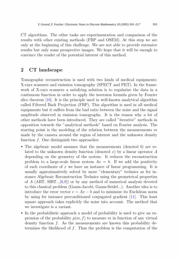
Tomographic reconstruction is used with two kinds of medical equipments:X-rays scanners and emission tomography (SPECT and PET). In the frame-work of X-rays scanners a satisfying solution is to regularize the data in acontinuous function in order to apply the inversion formula given by Fourierslice theorem [10]. It is the principle used in well-known analytical algorithmcalled Filtered Back Projection (FBP). This algorithm is used in all medicalequipments but it suffers from the bad ratio between the noise and the signalamplitude observed in emission tomography. It is the reason why a lot ofother methods have been introduced. They are called ”iterative” methods inopposition towards the ”analytical methods” based on Fourier analysis. Thestarting point is the modeling of the relation between the measurements mmade by the camera around the region of interest and the unknown densityfunction f . One distinguish two approaches:
• The algebraic model assumes that the measurements (denoted b) are re-lated to the unknown density function (denoted x) by a linear operator Adepending on the geometry of the system. It reduces the reconstructionproblem to a large-scale linear system Ax = b. If we add the positivityof each coordinate of x we have an instance of linear programming. It isusually approximatively solved by more ”elementary” technics as for in-stance Algebraic Reconstruction Technics using the geometrical propertiesof A (ART, SIRT...[6,9]) or by any method of numerical analysis devotedto this classical problem (Gauss-Jacobi, Gauss-Seidel...). Another idea is tointroduce the error vector e = Ax − b and to minimize its Euclidean normby using for instance preconditioned conjugated gradient [11]. This leastsquare approach takes explicitly the noise into account. The method thatwe investigate is a variant.
• In the probabilistic approach a model of probability is used to give an ex-pression of the probability p(m, f) to measure m in function of any virtualdensity function f . As the measurements are known this probability de-termines the likelihood of f . Thus the problem is the computation of the
Y. Gerard, F. Feschet / Electronic Notes in Discrete Mathematics 20 (2005) 501–517 503

density function f that likelihood p(m, f) is maximal. This principle hasbeen first used in algorithm ML-EM (Maximum Likelihood-ExpectationMaximization [16]) and in its faster variants like OSEM...
These iterative methods have been deeply improved by using a priori in-formation coming for instance from a scanner associated to a PET or from anarbitrary choice of searching ”regular” solutions (see for instance [3]). Thisidea is formalized in probabilistic framework by Bayes theorem but its use isnot restricted to this area. The principle is to penalize the functions f whichdo not satisfy the additional request. The penalty modifies the kernel of theiteration process. Another approach is to add a filtering step between eachcomputation of a new current solution. The choice of the penalty (MedianRoot Prior, Gibbs prior...) and the use of a filter at each step provides a largenumber of variants of the basic algorithms.
3 DT and linear programming
The framework of DT is quite different because the function f is constrainedto take only discrete values 0 or 1 and also because the number of directions ismuch smaller than in CT applications (see [13] for a complete introduction).It is probably due to the reduced size of the input that the linear programmingapproach has been introduced in DT before than in CT.
The beginning of the story coincides with the birth of discrete tomographyas an identified field (DIMACS, Rutgers, 1992). It is explained by P. Fishburn,P. Schwander, L. Shepp, and R. Vanderbei in their paper [5] that the ideato use linear programming came to them after a talk of A. Kuba (about ajoined work with G.T. Herman and R. Aharoni [1]) where he did introducethe relaxed algebraic problem Ax = b with x ∈ [0, 1]d. Their idea was to solvethe linear system Ax = b under relaxed constraints x ∈ [0, 1]d (where A isthe linear operator of the line sums, b is the vector of the measurements andx is unknown). The drawback of this approach is that it does not supportany noise (just change one of the coordinates of b from 1 and you obtain anunfeasible linear program).
The second step has been the relaxation of equality Ax = b by P. Gritz-mann, S. de Vries, and M. Wiegelmann [7] for being able to work with noisydata. There are two dissymetrical ways to relax the equality Ax = b either byconsidering Ax < b or Ax > b. The choice of one or the other leads to sym-metric methods Best-Inner-Fit or Best-Outer-Fit. The second difference withinitial approach was the introduction of an objective function. Maximization
Y. Gerard, F. Feschet / Electronic Notes in Discrete Mathematics 20 (2005) 501–517504

of 1l.x in BIF (minimization in BOF) guarantees that Ax will be close to b (ifthe value at a pixel is not 1, almost one line sum containing it is equal to thecorresponding projection).
The third step has been the introduction of a penalty function by S. Weber,C. Schnorr, and J. Hornegger [18]. The idea was already rather classicalin CT but it has been nicely associated to previous approach by adding alinear penalty function p(x) to the objective function 1l.x. The penalty p(x)characterizes the disorder of x. It is is a kind of entropy. Its expressionrequires to introduce auxiliary variables and constraints. The size of the inputof the linear program is multiplied by a constant but the result is much nicer.This algorithm has been the starting point of our interest in the question.We have been interested in improving some steps of the computation and ininvestigating the efficiency of this natural approach.
The last step has been the regularization of the dissymmetry of Ax < b orAx > b by working with the error vector e = Ax − b. We distinguish threevariants depending on a norm chosen between ||.||1, ||.||∞ and ||.||2:
• we can consider the linear constraints −h ≤ Ax − b ≤ h with x ∈ [0, 1]d
and choose the sum∑
i hi of the coordinates of h as linear objective func-tion. Its minimization guarantees
∑i hi = ||Ax − b||1 and thus ||Ax − b||1
minimization.
• we can also consider the constraints −h1l ≤ Ax− b ≤ h1l (where h is now areal and not a vector) with x ∈ [0, 1]d and choose h as objective function. Itsminimization guarantees h = ||Ax−b||∞ and thus ||Ax−b||∞ minimization.
• we should also notice that the two previous variants with ||.||1 or ||.||∞are similar to the least square approach of CT where the euclidian norm||Ax − b||2 is minimized.
As in Weber et al. initial work [18] the objective function (∑
i hi, h, or thequadratic expression
∑i h
2i in case of least square approach) can still be com-
bined with a linear penalty function p(x) directing the computation towards”smooth” solutions.
• The regularized least square approach (||.||2) has already been investigatedby A. Kaufman in [11] with a quadratic penalty function. We find it alsoin the framework of discrete tomography in Weber et al. extended versionof [18]. It is a problem of quadratic optimization under constraints of pos-itivity. It is usually solved by preconditioned conjugated gradient [12] butwe can also think of using modern tools of convex optimization as interiorpoints methods.
Y. Gerard, F. Feschet / Electronic Notes in Discrete Mathematics 20 (2005) 501–517 505

• The regularized uniform norm approach (||.||∞) has been simultaneouslyand independently developed by S. Weber, T. Schule, J. Hornegger and C.Schnorr (they did present it at IWCIA 2004 in december [19]) and us (wedid present it at DGCI 2005 in april [4]). Our tasks were different since thework of Weber et al. is devoted to discrete tomography (in [19] the linearprogramming approach is combined with a Difference-Convex algorithm inorder to obtain step by step a binary solution) while we are focused on CTapplications.
• The regularized ||.||1 approach seems original.
4 Method
The task of the paper is to investigate the interest of the linear programmingapproach in CT.
4.1 A linear operator based on digital lines
In the linear programming approach the algebraic relation between the mea-surements b and the unknown density function x is modelled by a linear oper-ator A (the unknown x is related to b by equation Ax = b). It is not sufficientto know the geometry of the system to obtain A. There are some choices todo.
First choice: choose a geometrical model. It can be the length ray modelwhere the contribution of each pixel in a line sum is weighted by the lengthof their intersection. It can also be a ”Dirac” model where the pixels areconsidered as atoms with the consequence that their contribution in a ”line”containing them is always 1 (Fig. 1). We should however precise what weintend by line. The naive idea would be to work with ”Diophantine” straightlines namely the lattice points belonging to real lines. The problem with thisapproach is that the gap between consecutive parallel lines depends on theirdirection (it is for instance 1 with vertical or horizontal lines while it is 2−1/2
with diagonal directions). This approach could be applied in practice if thecameras were using a various resolution in function of the chosen directionbut it is not the case. It is the reason why we chose to work with digitallines. This notion has been introduced by J-P. reveilles in the beginning of thenineties [15]. The idea is to work with digital lines of fixed ”thickness” (namelythe subsets of lattice points belonging to strips having a fixed thickness).It provides a model which seems consistent with the fixed resolution of thecamera and which is an alternative to the length ray model. The advantage
Y. Gerard, F. Feschet / Electronic Notes in Discrete Mathematics 20 (2005) 501–517506

of this model towards the length ray model is to give the same weight to eachpixel (1) while we can imagine having with the length ray model the extremecase where a pixel (with a high resolution of the reconstructed image) doesnot cross any real line used in the length ray model. Thus its weights would beall 0 with the consequence that its value would be undetermined. It can nothappen in the digital line model. The ”digital lines” model allows to disconnectcompletely the resolution of the reconstructed image from the resolution of thecamera without introducing the structural artifacts that the length ray modelcan theoretically create.
Fig. 1. In the length ray model, the value of the blue pixel in the line sum isweighted by the length of the red segment. In the ”digital line” model, the weightof each pixel in the digital line which contain it is 1.
Second choice: take the absorption into account or in other words chooseits parameters. We have decided in our implementation to fix arbitrary theabsorption coefficient of the center of the image to 1 while the ones of theother pixels depend on their location in the beginning or the end of the linesegments (absorption(x) = A exp(a.x) where a is directed by the consideredline). We choose the ratio between the forward pixel and the backward oneas parameter of the reconstruction method. Until now we have always fixedit arbitrarily.
Y. Gerard, F. Feschet / Electronic Notes in Discrete Mathematics 20 (2005) 501–517 507

4.2 Error minimization
Instead of solving the linear system Ax = b or its dissymmetric variant Ax ≤ bwe work with the error vector e = Ax − b. Linear programming allows tominimize its uniform norm ||Ax− b||∞ or its 1-norm ||Ax− b||1 by taking intoaccount the constraints x ∈ [0, 1]d.
The choice of the linear programming algorithm is open but it should beable to deal with several thousands of variables and much as constraints. Dueto the size of the input the efficiency of the chosen algorithm is a critic pointof the ”linear programming” approach. The choice of interior points methodsseems all the more natural that it provides a general algorithm which remainsin the old tradition of iterative algorithms.
4.3 A priori regularization
We add to the objective ||Ax− b|| a linear penalty p(x). Its purpose is to pe-nalize the reconstructed images x which are not regular. The penalty functionp(.) should be encoded carefully in order to guarantee its linearity. The trickintroduced in DT by Weber et al. [18] is to use auxiliary variables. We haveencoded four different penalty functions:
• The ”edge” penalty introduced in [18] uses an auxiliary variable (lets say yi)for each edge i between neighboring pixels (lets say i′ and i′′). This variableappears in two constraints yi ≥ xi′ − xi′′ and yi ≥ xi′′ − xi′ . It followsyi ≥ |xi′ − xi′′ |. The chosen penalty function is f(x) = K
∑i yi where K
is a positive constant. By minimization it is equal to K∑
i |xi′ − xi′′ | thatvalue is a kind of measurement of the smoothness of x.
• The penalty that we have introduced in [4] is a dissymmetric variant (”dis-symmetric edge” penalty). We only take the constraints yi ≤ x′
i andyi ≤ xi′′ . Thus we have yi ≤ min{xi′ , xi′′}. We choose −K
∑i yi as penalty.
By minimization we encourage large values for neighboring pixels. The badpoint of the two previous penalties is that they multiply the number ofvariables by nearly 3.
• Another linear penalty that we have encoded is usually known as MedianRoot Prior (MRP). We take an auxiliary variable for each pixel (againdenoted yi) and count as penalty the absolute value of difference betweenthe value at pixel i and the mean of the values around it. We code itwith the linear constraints yi ≥ xi − mean{xi′/i
′ ∈ neighborhood(i)} andyi ≥ mean{xi′/i
′ ∈ neighborhood(i)} − xi}. We take K∑
i yi as penalty.The number of variables is multiplied by 2.
Y. Gerard, F. Feschet / Electronic Notes in Discrete Mathematics 20 (2005) 501–517508

• Another idea is to use a cross penalty: for each pixel, the auxiliary variableverifies yi ≥ xih+ + xih− − xjv+ − xjv− and yi ≥ xjv+ + xjv− − xih+ − xih−
where the four pixels ih+, ih− (h for horizontal) and iv+, iv− (v for vertical)make a cross around pixel i.
All these penalties can be combined linearly and we can imagine manyother ways to measure the disorder of x with auxiliary variables and linearconstraints. The relative weight of the error on projections ||Ax− b|| towardsdisorder penalty is controlled by the constant K. Its choice as the one of theabsorption has been always fixed arbitrarily.
5 Experiments
5.1 Challenge
We have seen in [4] that the linear programming approach with ||.||∞ andentropic regularization was able to reconstruct numerical phantoms from onlyfew projections (16 directions provide a satisfying reconstruction of 64 × 64images). The projections were considered without any noise (the images couldbe noisy but we did consider their exact projections through digital lines). Wethink that the approach allows to deal with noisy projections but we did noexperiment. We want to test it directly on real images coming from nuclearmedicine.
The nuclear medicine center Jean-Perrin of Clermont-Ferrand (UMR 484-INSERM-France) has provided us the SPECT projections of a thorax (Fig.2) and the reconstructed images of a myocard (Fig. 3) that their equipmentsprovide them (FBP and OSEM reconstruction): the projections are 30 greylevels images of size 64 × 64 corresponding to 30 angles going from 0 to 174(angular step 6). We had in fact 8 sequences of 30 images corresponding to8 steps of the cardiac cycle but we have only worked on the first sequence.Anyway the resolution of the projections is very low since the 64 columns ofeach image correspond to the width of the thorax. It makes the problem hardbecause the heart image that the physician want to see are only a small part ofthe image. The low resolution of the projections and their noise explain thatthe FBP and OSEM reconstructed images are of very poor quality. We shouldadd that at this step we do not know the exact process which has providedthese images. The algorithms are FBP and OSEM but it is just an indicationon the method. It does not say if some other process have been done on theimages. Their overall aspect lets believe that some transformations may havebeen applied in order to return to physicians more homogenous images.
Y. Gerard, F. Feschet / Electronic Notes in Discrete Mathematics 20 (2005) 501–517 509

Fig. 2. The first sequence of 30 projections from a thorax (grey-scale images of size64 × 64). The projections of the heart are the small grey circles in the upper partof each image.
Fig. 3. Two transversal cuts reconstructed by FBP (left) and OSEM (right).
In spite the ugliness of the reconstructed images our first challenge is notto do real better. We are only at the beginning of the investigation of the
Y. Gerard, F. Feschet / Electronic Notes in Discrete Mathematics 20 (2005) 501–517510

linear programming approach in this realistic framework and we have to takeinto account the fact that even the best algorithm can not use an anatomicinformation which is not in the input.
5.2 Results
Our reconstruction by linear programming has several parameters:
• the size of the reconstructed image,
• the norm (||.||1 or ||.||∞),
• the absorption ratio,
• the parameter K controlling the relative importance of error minimizationtowards entropic regularization,
• the penalty (”edge” entropy, dissymmetric ”edge” entropy, MRP, cross en-tropy, ...),
• the starting angle of the reconstruction
• and of course the height of the transversal cut that we try to reconstruct.
Due to the large number of parameters we did not investigate all possiblecases. We have only worked with ||.||1 minimization and the ”edge” penaltyon three consecutive levels in the projections corresponding to the height ofthe heart (Fig. 4).
Fig. 4. On the first projection the three levels of the transversal cut that we want toreconstruct are covered by the three horizontal lines of height 22, 23 and 24 (fromthe top).
The overall aspect of the all the images that we obtain is different fromthe one of the transversal cut obtained by using OSEM and FBP (as we have
Y. Gerard, F. Feschet / Electronic Notes in Discrete Mathematics 20 (2005) 501–517 511

Fig. 5. A 64 × 64 cut of height 22 reconstructed by ||.||1 minimization with the”edge” penalty weighted by K = 1.25 and an absorption ratio equal to 2 (startingangle of 40 degrees.
received them). Our results are less regular (see for instance Fig. 5 comparedto Fig. 3).
5.3 Influence of the parameters
5.3.1 Parameter K controlling the weight of the penalty
Increasing the value of K leads to more homogenous images which can becomecompletely uniform if K is too large. This effect is illustrated by Fig 6.
Fig. 6. The 32 × 32 cuts of height 22 reconstructed by ||.||1 minimization with the”edge” penalty weighted by K = 1 and K = 5 (absorption ratio equal to 2 andstarting angle of 40 degrees).
Y. Gerard, F. Feschet / Electronic Notes in Discrete Mathematics 20 (2005) 501–517512

5.3.2 Absorption ratio
The influence of the absorption is visible on the projections. We can see itclearly on the loin that grey-level increases if they are located forward thecamera. Thus we have to take it into account.
Fig. 7. The 64 × 64 cuts of height 23 reconstructed by ||.||1 minimization with the”edge” penalty weighted by K = 0.75 and a varying absorption ratio equal to 1.5,2, 2.5 and 3 (starting angle equal to 0).
The quality of the images that we have obtained with an absorption ratiogoing from 1.5 to 3 increases with the absorption (Fig. 7) but the reconstructedimages are less sensitive to it as what we thought before experiments. Theyare only small differences between them. We have now to experiment whathappens with larger values.
5.3.3 Starting angle
A natural choice would be to consider that the angles of the projection (theangles of the camera) go from 0 until 180 degrees. We can also consider thatthey go from θ until θ + 180. We can wait from a method of reconstructionthat it provides images with angles θ and θ′ which only differ from a rotationof angle θ′ − θ. We have tested this invariance by computing the sequence ofimages drawn Fig. 7 with a starting angle θ equal to 40 degrees. The resultsare drawn Fig. 8.
We can observe in both images the two opposite sides of the heart havingthe largest grey-levels (the white points). We observe also in all Fig. 7 andFig. 8 images that there are two cavities in the heart. We can think thatit is an artefact of a bad reconstruction but the fact that it is present in allimages leads to think the contrary. The two small black area in the heartcould correspond to the ventricles.
The concord of the corresponding images with different starting angles isquite satisfying but we can also observe in the right low corner of Fig. 8 imagesa grey area which does not correspond to reality. We can see such artifacts of
Y. Gerard, F. Feschet / Electronic Notes in Discrete Mathematics 20 (2005) 501–517 513

Fig. 8. The 64 × 64 cuts of height 23 reconstructed by ||.||1 minimization with the”edge” penalty weighted by K = 0.75 and a various absorption ratio equal to 1.5,2, 2.5 and 3). The starting angle is θ = 40◦ (the range of the angles is [40, 220]).
reconstruction in all images. They correspond to pixels which belong to lessdigital lines than the pixels of center. What can be done to avoid this effect?The question is open.
5.3.4 Penalty
We have reconstructed an image by using the ”dissymmetric edge” penaltyinstead of the ”edge” penalty (Fig. 9).
Fig. 9. The 64 × 64 cuts of height 24 reconstructed by ||.||1 minimization withthe ”edge” penalty (left) and the ”dissymmetric edge” penalty (right) weighted byK = 1.25 without absorption (ratio equal to 1) and a starting angle of 40 degrees).
The image obtained with the ”dissymmetric edge” penalty is of betterquality but it is not enough to conclude.
Y. Gerard, F. Feschet / Electronic Notes in Discrete Mathematics 20 (2005) 501–517514

5.4 Time of computation
The reconstruction of an image by the linear programming approach is inthree steps:
• step 1: write the linear program from the projections.
• step 2: solve the linear program (we have used Soplex [20]).
• step 3: create an image from the result of the linear program.
The steps 1 and 3 take a time which is completely negligible towards the timenecessary to solve the linear program. Without trying any optimization thesecond step takes 15 minutes for reconstructing a 32 × 32 image and 6 hoursfor reconstructing a 64× 64 image. It is a major drawback but there are a lotof perspectives to reduce it.
5.5 Perspectives
The solvation of the linear program is too much time consuming because thenumber of variables is very large (14080 for reconstructing a 64×64 image with”edge” penalty). Do we need so much variables whereas the heart is only in aregion of 20 × 20 pixels in a 64 × 64 image? The 400 variables correspondingto these pixels (1200 if we count the auxiliary variables and 3120 with theerrors on the projections) can not be eliminated since the core of the problemis precisely to give them a value. What about the 10960 other variables?Are they really necessary? We think that it is useless to work with all ofthem. If we know that some of these pixels belong to an homogenous region,it is not necessary to attribute them different variables. These pixels can berepresented in the linear program by the same variables. It is a kind of multi-resolution principle. It remains the question to determine these homogenousregions. A previous computation with a lower resolution (for instance a 32×32image) could be used to locate them. It leads to the idea of using a sequenceof linear programs computing images with an increasing resolution.
The idea is to use a multi-resolution approach with a lot of variables forthe region of interest and only few variables for the remaining areas. We canthink about quad-trees. The application of such approach would not changemany things in the implementation (the question of the contribution of eachcell to the projections can be solved by keeping the length ray model withoutchanging anything or by using areas or number of points as weights in the”Dirac” models). The principle would be for instance to reconstruct a currentquad-tree image and then to determine the cells which should be divided forthe next computation.... We hope that such an approach would lead to linear
Y. Gerard, F. Feschet / Electronic Notes in Discrete Mathematics 20 (2005) 501–517 515

programs which could be solved in a few minutes.
The last improvement that we suggest is to include in the linear programsome information concerning the grey-level of some regions. If it is knownfrom a previous computation or from another equipment that the grey levelof a given cell should be λ times smaller than the grey level of another one,this information can be easily encoded in the linear program.
6 Conclusion
The linear programming approach is a promising framework for reconstructingCT images but it will not be possible to use it in practice as long as the timeof computation will not be reduced. It requires certainly to eliminate manyuseless variables and probably to introduce a multi-resolution approach thatinvestigation could be the task of future works.
References
[1] Aharoni, R., G. Herman and A. Kuba, Binary vectors partially determined bylinear equation systems, Discrete Mathematics 171 (1997), 1–16.
[2] Censor, Y. and S. Matej, Binary steering of nonbinary iterative algorithms,in: A. Kuba and G. Herman, editors, Discrete Tomography: Foundations,Algorithms, and Applications Birkhauser, Boston (1999), 285–296.
[3] Depierro, A., Modified expectation maximization algorithm for penalizedlikelihood estimation in emission tomography, IEEE Trans. Med. Imag. 14
(1995), 132–137.
[4] Feschet, F. and Y. Gerard, Computerized tomography with digital lines andlinear programming, in: 12th Discrete Geometry and Computer Imagery,Springer Verlag LNCS 3429 (2005), 126–135.
[5] Fishburn, P., P. Schwander, L. Shepp and R. Vanderbei, The discrete radontransform and its approximate inversion via linear programming, DiscreteApplied Math. 75 (1997), 39–61.
[6] Gordon, R., A tutorial on ART (Algebraic Reconstruction Techniques), IEEETransactions on Nuclear Science NS-21 (1974), 31–43.
[7] Gritzmann, P., S. de Vries and M. Wiegelmann, Approximating binary imagesfrom discrete X-rays, SIAM J. Optimization 11 (2000), 522–546.
Y. Gerard, F. Feschet / Electronic Notes in Discrete Mathematics 20 (2005) 501–517516

[8] Herman, G., Reconstruction of binary patterns from a few projections, in:International Computing Symposium, LNCS 18 (1973), 371–378.
[9] Herman, G. and L. Meyer, Algebraic reconstruction techniques can be madecomputationally efficient, IEEE Trans. Med. Imag. 12 (1993), 600–609.
[10] Kak, A. and M. Slaney, “Principles of Computerized Tomographic Imaging,”IEEE Press, 1988.
[11] Kaufman, L., Maximum likelihood, least squares and penalized least squares forpet, IEEE Trans. Med. Imag. 12 (1993), 200–214.
[12] Kaufman, L. and A. Neumaier, Pet regularization by envelope guided conjugategradients, IEEE Trans Med Imag 15 (1996), 385–389.
[13] Kuba, A. and G. Herman, Discrete tomography: A Historical Overview,in: A. Kuba and G. Herman, editors, Discrete Tomography: Foundations,Algorithms, and Applications Birkhauser, Boston (1999), 3–34.
[14] Radon, J., Uber die bestimmung von funktionen durch ihre integralwertelangs gewisser mannigfaltigkeiten, Berichte der Schsischen Akademie derWissenschaften 69 (1917), 262–277.
[15] Reveilles, J.P., “Geometrie discrete, calcul en nombres entiers et algorithmique,”These d’etat, Universite ULP - Strasbourg 1991.
[16] Shepp, L. and Y. Vardi, Maximum likelihood reconstruction for emissiontomography, IEEE Trans. Med. Imag. 1 (1982), 113–122.
[17] Vardi, Y. and C. Zhang, Reconstruction of binary images via the em algorithm,in: A. Kuba and G. Herman, editors, Discrete Tomography: Foundations,Algorithms, and Applications Birkhauser, Boston (1999), 297–316.
[18] Weber, S., C. Schnorr and J. Hornegger, A linear programming relaxationfor binary tomography with smoothness priors, in: 9th Int. Workshop onCombinatorial Image Analysis, Electronic Notes in Discrete Math. 12 (2003).
[19] Weber, S., T. Schule, J. Hornegger and C. Schnorr, Binary tomography byiterating linear programs from noisy projections, in: 10th Int. Workshop onCombinatorial Image Analysis, Springer Verlag LNCS 3322 (2004), 38–51.
[20] Wunderling, R., “Paralleler und Objektorientierter Simplex-Algorithmus,”Ph.D. thesis, ZIB TR 96-09, Berlin 1996.
Y. Gerard, F. Feschet / Electronic Notes in Discrete Mathematics 20 (2005) 501–517 517