Annealing effects on the structure and magnetic properties of Ni/Ti multilayers
14
INSTITUTE OF PHYSICS PUBLISHING JOURNAL OF PHYSICS: CONDENSED MATTER J. Phys.: Condens. Matter 16 (2004) 5569–5582 PII: S0953-8984(04)77446-9 Annealing effects on the structure and magnetic properties of Fe–C granular films W B Mi 1 , Z Q Li 1 , P Wu 1 , E Y Jiang 1 and H L Bai 1,2,3 1 Tianjin Key Laboratory of Low Dimensional Materials Physics and Preparing Technology, Institute of Advanced Materials Physics, Faculty of Science, Tianjin University, Tianjin 300072, People’s Republic of China 2 Key Laboratory for Advanced Ceramics and Machining Technology of Ministry of Education, Tianjin University, Tianjin 300072, People’s Republic of China E-mail: [email protected] and [email protected] Received 8 March 2004, in final form 8 June 2004 Published 16 July 2004 Online at stacks.iop.org/JPhysCM/16/5569 doi:10.1088/0953-8984/16/30/017 Abstract Fe–C granular films with different Fe volume fraction x v were fabricated using a DC facing-target sputtering system at room temperature and subsequently annealed at different temperatures. X-ray diffraction and selected area electron diffraction analyses indicate that as-deposited and low-temperature annealed (350 ◦ C) samples are composed of amorphous Fe and C, and higher temperature annealing makes the amorphous Fe transform to α-Fe, which is also confirmed by high-resolution transmission electron microscopy. Magnetic measurements indicate that at room temperature the as-deposited Fe–C (x v = 58) granular films are superparamagnetic and annealed ones are ferromagnetic. The coercivity of 100 nm thick Fe–C (x v = 58) granular films increases with annealing temperature (for 1 h) and time (at 450 ◦ C). The coercivity of the 100 nm thick Fe–C (x v = 58) samples annealed at temperatures ranging from 400 to 500 ◦ C decreases linearly with measuring temperature T , signalling a domain wall motion mechanism. For the samples annealed at 550 ◦ C, the change of in-plane coercivity with T satisfies the relation H c ∼ T 1/2 , reflecting that this system behaves better as a set of Stoner–Wohlfarth particles. It was also found that there exists a critical thickness (∼133 nm) for the 450 ◦ C annealed (for 1 h) Fe–C (x v = 58) granular films with thickness in the range 100–200 nm, below and above which the magnetization reversal is dominated by domain wall motion and by Stoner–Wohlfarth rotation, respectively. 3 Author to whom any correspondence should be addressed. 0953-8984/04/305569+14$30.00 © 2004 IOP Publishing Ltd Printed in the UK 5569
-
Upload
independent -
Category
Documents
-
view
3 -
download
0
Transcript of Annealing effects on the structure and magnetic properties of Ni/Ti multilayers

INSTITUTE OF PHYSICS PUBLISHING JOURNAL OF PHYSICS: CONDENSED MATTER
J. Phys.: Condens. Matter 16 (2004) 5569–5582 PII: S0953-8984(04)77446-9
Annealing effects on the structure and magneticproperties of Fe–C granular films
W B Mi1, Z Q Li1, P Wu1, E Y Jiang1 and H L Bai1,2,3
1 Tianjin Key Laboratory of Low Dimensional Materials Physics and Preparing Technology,Institute of Advanced Materials Physics, Faculty of Science, Tianjin University, Tianjin 300072,People’s Republic of China2 Key Laboratory for Advanced Ceramics and Machining Technology of Ministry of Education,Tianjin University, Tianjin 300072, People’s Republic of China
E-mail: [email protected] and [email protected]
Received 8 March 2004, in final form 8 June 2004Published 16 July 2004Online at stacks.iop.org/JPhysCM/16/5569doi:10.1088/0953-8984/16/30/017
AbstractFe–C granular films with different Fe volume fraction xv were fabricated usinga DC facing-target sputtering system at room temperature and subsequentlyannealed at different temperatures. X-ray diffraction and selected areaelectron diffraction analyses indicate that as-deposited and low-temperatureannealed (�350 ◦C) samples are composed of amorphous Fe and C, andhigher temperature annealing makes the amorphous Fe transform to α-Fe,which is also confirmed by high-resolution transmission electron microscopy.Magnetic measurements indicate that at room temperature the as-depositedFe–C (xv = 58) granular films are superparamagnetic and annealed ones areferromagnetic. The coercivity of 100 nm thick Fe–C (xv = 58) granularfilms increases with annealing temperature (for 1 h) and time (at 450 ◦C). Thecoercivity of the 100 nm thick Fe–C (xv = 58) samples annealed at temperaturesranging from 400 to 500 ◦C decreases linearly with measuring temperature T ,signalling a domain wall motion mechanism. For the samples annealed at550 ◦C, the change of in-plane coercivity with T satisfies the relation Hc ∼ T 1/2,reflecting that this system behaves better as a set of Stoner–Wohlfarth particles.It was also found that there exists a critical thickness (∼133 nm) for the 450 ◦Cannealed (for 1 h) Fe–C (xv = 58) granular films with thickness in the range100–200 nm, below and above which the magnetization reversal is dominatedby domain wall motion and by Stoner–Wohlfarth rotation, respectively.
3 Author to whom any correspondence should be addressed.
0953-8984/04/305569+14$30.00 © 2004 IOP Publishing Ltd Printed in the UK 5569

5570 W B Mi et al
1. Introduction
Nanocomposite films, consisting of nanoscale ferromagnetic metal particles, such as Fe, Co, Nior their alloys, embedded in a host matrix, for example Cu, Ag, C, SiO2, Al2O3, AlN, BN, etc,exhibit many interesting properties, such as enhanced coercivity, superparamagnetism, giantmagnetoresistance or tunnelling magnetoresistance originating from finite-size and interfaceeffects [1], and have many possibilities for use in various technological applications, such ashigh-density magnetic recording [2, 3]. Generally, magnetic metal particles are immisciblewith a non-magnetic matrix,unless prepared by rapid quenching techniques, such as sputtering.The interactions between magnetic particles affect the coercivity of magnetic granular filmsgreatly. However, optimum ferromagnetic metal composition, a suitable host matrix andcomplete phase segregation between magnetic particles and the non-magnetic matrix canreduce the interaction between magnetic granules. In this case, the volume fraction of themagnetic component is generally below the percolation threshold, and the well isolatedmagnetic particles are small enough to become magnetically single domain structures, inwhich the magnetic moment only rotates during the magnetizing procedure, causing highcoercivity. Complete phase segregation between the particles and the matrix can be achieved byfabricating magnetic granular films at elevated substrate temperature and subsequent annealingat higher temperatures. One of the suitable host matrix materials is C because it can providegood magnetic isolation between neighbouring particles and reduce the interparticle exchangecoupling [4]. Another important feature of C is that it can also protect the core material againstoutside degradation such as corrosion and attack by concentrated acids [5, 6]. Several groupshave studied the structural and magnetic properties of Fe–C nanocomposite films preparedby different techniques, and revealed that the morphology and structure of ferromagneticmetal granular films are sensitive to preparation methods and conditions [7, 8]. In this paper,the Fe–C granular films were fabricated by a DC facing-target sputtering system at roomtemperature and subsequently annealed at different temperatures and time in 10−4 Pa vacuum.The annealing effects on the microstructures and magnetic properties were investigated indetail by using atomic force microscopy (AFM), x-ray photoelectron spectroscopy (XPS), x-ray diffraction (XRD), high-resolution transmission electron microscopy (TEM) and vibratingsample magnetometry (VSM).
2. Experimental details
The Fe–C (45 � xv � 85) granular films with different Fe volume fraction xv were fabricatedby a DC facing-target sputtering system at room temperature. The distance between the twotargets 100 mm in diameter was 100 mm. The base pressure of the chamber was better than2.0 × 10−4 Pa and sputtering was carried out in a 0.5 Pa Ar (99.999%) atmosphere. One ofthe two targets was pure graphite (99.999%), and the other was pure Fe (99.999%) on whicha piece of pure graphite (99.999%) was placed. The composition was controlled by changingthe diameter of the C piece. The sputtering power was 190 W and the deposition rate was∼0.3 Å s−1. The thickness of the Fe–C films with different Fe volume fraction xv was set atabout 100 nm, except for Fe–C (xv = 58) granular films whose thickness ranges from 100to 200 nm. Cleaved NaCl, Si(100) wafers and microscope glass cover slips were used assubstrates. All of the as-deposited Fe–C granular films were subsequently annealed at 450 ◦Cfor 1 h in a 10−4 Pa vacuum. Some of the as-deposited 100 nm thick Fe–C (xv = 58) granularfilms on Si(100) wafer were annealed at temperatures ranging from 350 to 550 ◦C for 1 h, andat 450 ◦C for 30, 60, 90 and 120 min.
For planar-view TEM observation, we used free-standing Fe–C films, which weredeposited on cleaved NaCl substrates and subsequently floated on distilled water to dissolve the

Annealing effects on the structure and magnetic properties of Fe–C granular films 5571
(a) (b)
(c) (d)
Figure 1. Planar-view bright field TEM images of 100 nm thick as-deposited Fe–C granular filmswith different Fe volume fractions: (a) xv = 49, (b) xv = 58, (c) xv = 65 and (d) xv = 84.
NaCl substrates. The composition of these granular films was analysed by XPS using Mg Kα
radiation (1253.6 eV) with a resolution of about 0.25 eV. In order to remove the contaminatedsurface layer, Ar ions with 2 keV energy, a current density of 1 mA mm−2 and an incident angleof 45◦ were used to sputter the samples. The microstructure of the samples was analysed byXRD and selected area electron diffraction (SAED). The thickness of the films was measuredby a Dektak profiler and also by calibrating the deposition rate. The magnetic properties weremeasured by a VSM at different temperatures and angles.
3. Results and discussion
3.1. Morphology and structure
Figure 1 gives the planar-view bright field TEM images of 100 nm thick as-deposited Fe–Cgranular films with different Fe volume fraction xv. All the as-deposited Fe–C granular filmsare composed of ∼2–6 nm Fe granules embedded in a C matrix, which is the typical morphologyof granular films. The granules are not regular but elliptical, and the size distribution is largewhen the Fe volume fraction is 49. At xv = 84, Fe granules connect with each other becausethe Fe volume fraction is far above the percolation threshold (about 0.5–0.55). It is also clearthat the Fe–C (xv = 58) sample possesses relatively good granular structure with uniformgrain size, as shown in figure 1(b), although some of the granules touch.
Figure 2 shows AFM micrographs of as-deposited and annealed Fe–C (xv = 58) granularfilms deposited on Si(100). The surface roughness Ra is defined as the arithmetic average

5572 W B Mi et al
(a)
(b)
(c)
Figure 2. AFM micrographs of Fe–C (xv = 58) granular films deposited on Si(100): (a) as-deposited, (b) annealed at 450 ◦C for 1 h and (c) annealed at 550 ◦C for 1 h.
deviation from the mean line within the assessment length La
Ra = 1
L
∫ x=La
x=0|y| dx, (1)
where x is the displacement along the lateral scan direction and y is the vertical fluctuation.One can see from the figure that when annealing temperature increases, the average surfaceroughness of Fe–C (xv = 58) granular films increases due to phase segregation, crystallizationand increasing grain size. However, due to the aggregation of smaller particles, the Ra valueof the samples annealed at 550 ◦C is smaller than that of the samples annealed at 500 ◦C, asshown in table 1, where we list the Ra values of the as-deposited and annealed samples.
Figure 3 presents the XRD patterns of as-deposited and annealed Fe–C (xv = 58)granular films deposited on Si(100), indicating that the as-deposited and 350 ◦C annealedsamples are composed of amorphous Fe and C, and the amorphous Fe crystallizes to α-Feat higher annealing temperatures. At higher annealing temperatures of 500 and 550 ◦C, therelative intensity of α-Fe(110) increases, signalling a better crystallization at higher annealtemperatures. XPS measurements were performed with an emphasis on the peaks associatedwith Fe2p, C1s and O1s. The intensity of the C1s peak almost keeps constant after 3 min Ar+

Annealing effects on the structure and magnetic properties of Fe–C granular films 5573
400 oC
450 oC
α−Fe (110)
550 oC
350oC
as-deposited
500 oC
30 35 40 45 50 55 60
2θ (degree)
Inte
nsity
(ar
b.un
its)
Figure 3. XRD patterns of as-deposited and different temperature 1 h annealed Fe–C (xv = 58)granular films deposited on Si(100).
Table 1. The values of average roughness determined by AFM at different annealing temperatures.
Annealing temperature ( ◦C) Average roughness (nm)
As-deposited 1.433350 1.583400 1.693450 1.988500 6.249550 5.140
ion bombardment (2 keV), indicating that the surface contaminated C has been cleaned off.Moreover, after 5 min of Ar+ ion bombardment, the contaminated oxygen peaks also disappear.As shown in figure 4, the peaks situated at 284.6 and 707.5 eV in the C1s and Fe2p XPS spectraof as-deposited Fe–C (xv = 58) granular films are from pure C and metallic Fe, respectively.The shoulders located at 710.3 and 723.4 eV, at the high energy side of Fe 2p3/2 and 2p1/2
peaks, corresponds to the Fe2+ ions from FeO [9], which can be due to the small amount ofO2 remaining in the chamber and/or that mixed in the Ar gas (99.999%). In addition, no ironcarbide peaks (Fe2p 708.5 eV) are visible, suggesting that no carbides are formed during thedeposition, although Fe mixes with C in the incomplete phase-separating films.
Figure 5 shows the planar-view bright field TEM images and corresponding SAED patternsof 100 nm thick Fe–C (xv = 58) granular films annealed at 450 and 550 ◦C for 1 h, and thoseof as-deposited samples are also presented for comparison. It is seen from figure 5(a) thatthe as-deposited film is composed of ∼4 nm Fe grains separated by the C matrix, and theFe granules irregularly connect with each other because the Fe volume fraction in the filmsis near the percolation threshold. There are no sharp diffraction rings visible in the SAED

5574 W B Mi et al
740 730 720 710 700
300 295 290 285 280
Inte
nsity
(arb
.uni
ts)
707.5
720.5
Binding energy (eV)
710.3723.4
284.6
Inte
nsity
(arb
.uni
ts)
Binding energy (eV)
(b) Fe2p
(a) C1s
Figure 4. (a) C1s and (b) Fe2p XPS spectra for as-deposited Fe–C (xv = 58) granular films.
pattern (figure 5(a)), reflecting that both Fe and C are amorphous in the as-deposited samples,because the substrate temperature is too low for Fe and C to crystallize during the deposition.This is consistent with the XRD result presented in figure 3. In figure 6, we show the high-resolution TEM image of 100 nm thick as-deposited Fe–C (xv = 58) granular films, wherethe dark region corresponds to Fe particles and the bright area to C because of the differentdensities of amorphous Fe and C. It is thus clear that Fe and C phases have already separatedduring the film growth, although the segregation is not complete, just as in the case of Co–Cgranular films [10]. When the annealing temperature increases to 450 ◦C, the granules growto ∼12 nm (figure 5(b)) and the SAED pattern corresponds to polycrystalline α-Fe. The phasesegregation is more complete, and the Fe granules are embedded in the amorphous C matrix.Annealed at 550 ◦C, the granules grow to ∼50–100 nm, and the C phase has transformed fromamorphous C to graphite-like C, which can be ascribed to the catalysis of Fe particles on thegraphitization [11], as shown in figure 5(c). Figure 7 displays the high-resolution TEM imagesof Fe lattice fringes. The spacing of the particle shown in figure 7 is ∼0.2 nm, which is nearlyequal to that of bcc Fe(110) (0.21 nm), indicating that high temperature annealing significantlyimproves the crystallinity of Fe granules. The inset in figure 7 is the fast Fourier transform(FFT) image of the Fe lattice, obtained by using DigitalMicrograph software. Similar to SAED,FFT presents the diffraction pattern of a lattice in reciprocal space. There exists only a pairof dots and no other dots appear, indicating that only one set of lattices exists in figure 7, andfurther confirming the existence of the pure bcc Fe(110) phase (also see figure 5(c)).

Annealing effects on the structure and magnetic properties of Fe–C granular films 5575
(a)
(b)
(c)
Figure 5. Planar-view bright field TEM images of 100 nm thick Fe–C (xv = 58) granular films,(a) as-deposited, (b) annealed at 450 ◦C, (c) annealed at 550 ◦C, and corresponding SAED patterns.The inner ring is identified as graphite (002) and the outer ring as Fe bcc (110) in figure 5(c).
3.2. Magnetic properties
Figure 8 presents the in-plane M–H curves of 100 nm thick as-deposited Fe–C (xv = 58)granular films measured at room temperature and 80 K, showing that the samples aresuperparamagnetic at room temperature and soft ferromagnetic at 80 K, which indicate that theinteractions between ∼4 nm Fe granules exist in the 100 nm thick as-deposited Fe–C (xv = 58)granular films, and the interactions may include the dipolar interaction between the magneticparticles (direct) and exchange coupling through the Fe atoms buried in the C matrix (indirect)due to the incomplete phase segregation between Fe and C phases (see figure 6). However,these interactions are not enough to avoid superparamagnetism at room temperature. Underthe assumption of weak magnetic interaction between particles, the M–H curve measured at
5576 W B Mi et al
Figure 6. High-resolution TEM image of 100 nm thick as-deposited Fe–C (xv = 58) granularfilms.
Figure 7. High-resolution TEM, and corresponding fast Fourier transform, image of Fe–C(xv = 58) granular films annealed at 550 ◦C.
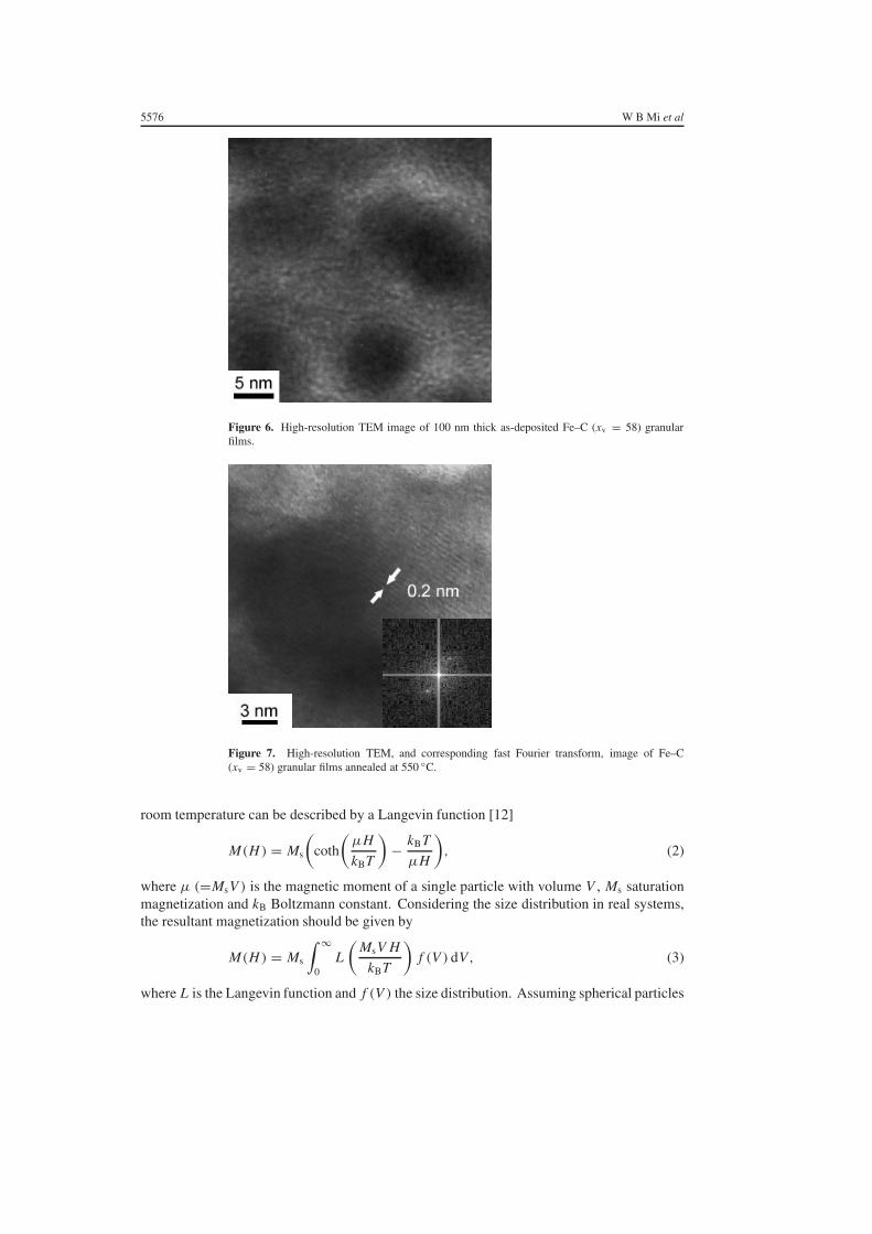
room temperature can be described by a Langevin function [12]
M(H ) = Ms
(coth
(µH
kBT
)− kBT
µH
), (2)
where µ (=MsV ) is the magnetic moment of a single particle with volume V , Ms saturationmagnetization and kB Boltzmann constant. Considering the size distribution in real systems,the resultant magnetization should be given by
M(H ) = Ms
∫ ∞
0L
(MsV H
kBT
)f (V ) dV , (3)
where L is the Langevin function and f (V ) the size distribution. Assuming spherical particles

Annealing effects on the structure and magnetic properties of Fe–C granular films 5577
-0.5 0.0 0.5-1
0
1
Experimental dataFitting data
(b)
1.2
0.8
0.4
0.0
-0.4
-0.8
1.2
0.8
0.4
0.0
-0.4
-0.8
-1.2-12 -8 -4 0 4 8 12
H (kOe)
M/M
s
(a)
Figure 8. In-plane magnetization curve of as-deposited Fe–C (xv = 58) granular films measuredat (a) room temperature and (b) 80 K.
of diameter D for simplicity, a log-normal size distribution
f (D) = 1√2π ln σ D
exp
[−
(ln D − ln D
)2
2(ln σ)2
], (4)
with ∫ ∞
0f (D) dD = 1, (5)
is most often used. The grain size obtained by fitting the magnetization curve of as-depositedFe–C (xv = 58) granular films is ∼4.5 nm and the value of ln σ is ∼0.3. The former isconsistent with the granule size estimated from the high-resolution TEM image shown infigure 6.
Figure 9 presents the in-plane and out-of-plane room-temperature M–H curves of the100 nm thick Fe–C (xv = 58) granular films annealed at 450 and 550 ◦C for 1 h, indicating thatthe easy axis is in the film plane. The saturation magnetization of the annealed 100 nm thickFe–C (xv = 58) granular films almost does not change with the annealing temperature rangingfrom 350 to 550 ◦C (for 1 h) and annealing time (at 450 ◦C). Figure 10 shows the in-planeroom-temperature coercivity versus annealing temperature and time for the annealed Fe–C(xv = 58) granular films. The in-plane coercivity measured at room temperature increases

5578 W B Mi et al
(b)
in plane
out of plane
in plane
out of plane
900
600
300
0
-300
-600
-900
600
300
0
-300
-600
-900-10 -5 0 5 10
H (kOe)
M (
emu/
cc)
(a)
Figure 9. In-plane and out-of-plane magnetization curves measured at room temperature of 100 nmthick Fe–C (xv = 58) granular films annealed at (a) 450 and (b) 550 ◦C.
with the increase of annealing temperature and time. For films annealed at 400 ◦C, the in-plane coercivity is ∼200 Oe. The following reasons may be responsible for the relativelysmall coercivity:
(1) the magnetic interactions, including dipolar interaction between ferromagnetic particlesand exchange coupling between granules via the Fe atoms dispersed in the C matrix, arestrong because the phase segregation is not complete, and
(2) the size of granules is smaller than that of granules annealed at higher temperatures.
In the literature, observation of long-range domain structures caused by exchange interactionsthrough the metallic matrix in heterogeneous granular alloys and by dipolar interactions inferromagnetic nanocomposites has been reported [13–18]. Therefore, the increase of coercivitywith annealing temperature and time are possibly in part due to the suppression of the formationof long-range domain structures caused by phase segregation and increase in granule size.

Annealing effects on the structure and magnetic properties of Fe–C granular films 5579
20 40 60 80 100 120
0
100
200
300
400
500
600
350 400 450 500 550
0
100
200
300
400
500
600
annealing time
Annealing time (min)
Hc //
(Oe)
annealing temperature
Annealing temperature (oC)
Figure 10. In-plane room-temperature coercivity as a function of annealing temperature (for 1 h)and time (at 450 ◦C), for the 100 nm thick Fe–C (xv = 58) granular films.
450 oC
Hc(
θ)/H
c //
Angle (degree)
Domain wall motion mode
500 oC550 oC
Stoner-wohlfarthrotation mode
00 15 30 45 60 75 90
1
2
3
Figure 11. Angular dependence of room-temperature coercivity for Fe–C (xv = 58) granular filmsannealed at different temperatures.
Figure 11 presents the angular dependence of room-temperature coercivity for Fe–C(xv = 58) granular films annealed at different temperatures. Also shown in the figureare the Hc(θ)/Hc‖ versus θ curves calculated based on the domain wall motion mode andthe Stoner–Wohlfarth rotation mode. The ideal domain wall motion mode should followthe Hc(θ) ∼ 1/ cos θ relation, where θ is the angle between the applied field and the filmplane [19]. It is suggested from the figure that the magnetization reversal mechanism changeswith annealing temperature. Below 500 ◦C, the magnetic reversal mechanism approximatelyobeys the ideal domain wall motion mode at angles smaller than 60◦, which can be ascribedto the fact that the granules are not completely independent of each other (see figure 5)and some magnetic interactions still exist between particles at low annealing temperatures.But at the angles above 60◦, the mechanism deviates from the ideal domain wall motion

5580 W B Mi et al
500 oClinear fit
400 oC450 oC
550 oC
T (K)
Hc // (
kOe)
T1/2fit
0.2
0.4
0.6
0.8
1.0
1.2
1.4
1.6
50 100 150 200 250 300
Figure 12. In-plane coercivity versus measuring temperature for Fe–C (xv = 58) granular filmsannealed at different temperatures for 1 h.
significantly. Thus the reversal mechanism seems to involve not only domain wall motion butalso a rotational mode. At 550 ◦C, the magnetization reversal can be well described by theStoner–Wohlfarth rotation mode over the whole angle range. This change in the magnetizationreversal mechanism is due to the complete segregation of granules during higher temperatureannealing, whose reversal mechanism has been proved experimentally to follow the Stoner–Wohlfarth rotation mode [20]. However, the out of plane coercivity of all annealed samples isnot zero (see figures 9 and 11), which does not critically follow the Stoner–Wohlfarth rotationmode with zero out-of-plane coercivity. This discrepancy may be due to the magnetostaticinteraction between magnetic particles that prevents the particle rotating at higher angles [21].
In order to further investigate the magnetization reversal mechanism, the temperaturedependence of Hc has been measured. Figure 12 shows the dependence of in-plane coercivityon the measuring temperature of Fe–C (xv = 58) granular films annealed at differenttemperatures for 1 h. The in-plane coercivity decreases monotonically with the increaseof measuring temperature, dropping from 1590 Oe at 80 K to 719.5 Oe at 295 K for asample annealed at 550 ◦C, 980.4 to 501 Oe for 500 ◦C, 748.5 to 378.3 Oe for 450 ◦C and434 to 210 Oe for 400 ◦C. This decrease in coercivity with temperature can be interpretedas the contribution of intrinsic temperature dependence of the anisotropy and magnetization,and thermal activation effects [17]. Assuming that the film consists of independent, alignedStoner–Wohlfarth particles, Hc(T ) can thus be given by [22, 23]
Hc(T ) = ηHK
[1 −
(25kBT
KuV
)1/2]
, (6)
where η = 1, Ku = Ms HK/2 and V is the particle volume. For the sample annealedat 550 ◦C, the tendency of the change of in-plane coercivity with T satisfies the relationHc ∼ T 1/2 (equation (5)), reflecting that the system behaves as a set of Stoner–Wohlfarthparticles. Bean and Livingstone suggested that the relation between coercivity and temperaturesatisfied the characteristic T 1/2 law for systems composed of monodisperse aligned particleswithout magnetic interactions [23, 24]. However, Pfeiffer et al reported that for an assembly ofrandomly oriented particles, Hc could be plotted against T 0.77 [25]. In our case, the maximummagnetic field was applied prior to measuring the coercivity so that the particles were aligned.Therefore, the particles should follow the T 1/2 law. But the coercivity of samples annealed

Annealing effects on the structure and magnetic properties of Fe–C granular films 5581
133 nm
Hc(
θ)/H
c //
Angle (degree)
166 nm 200 nm
100 nmdomain wallmotion model
Stoner-Wohlfarthrotation model
0.0
0.5
1.0
1.5
2.0
2.5
0 15 30 45 60 75 90
Figure 13. Angular dependence of room-temperature coercivity for 450 ◦C annealed Fe–C(xv = 58) granular films with different film thicknesses.
at 400, 450 and 500 ◦C decreases linearly with the increase of temperature, signalling thatthese systems are not composed of Stoner–Wohlfarth particles and a new mechanism shouldbe introduced to explain this behaviour. Gaunt [26] suggested that the coercivity caused bydomain wall pinning can be expressed as
Hc(T ) = H0
[1 −
(25kBT
E0
)β]
, (7)
where H0 is the coercivity at zero temperature, representing the intrinsic coercivity of materials,and E0 the domain wall energy. Obviously, the relations between in-plane coercivity andtemperature shown in figure 12 for the Fe–C (xv = 58) granular films annealed at 400, 450and 500 ◦C can be well described by equation (7), and each corresponds to β = 1 [19, 26].These indicate that the domain wall motion is the dominant mechanism for the coercivity.
Finally, the angular dependence of room-temperature coercivity for the 450 ◦C annealedFe–C (xv = 58) granular films with different film thicknesses is given in figure 13. It indicatesthat when the film thickness t < 133 nm, the magnetization reversal mechanism is mainlydomain wall motion, but at t � 133 nm, the magnetization reversal mechanism is dominatedby Stoner–Wohlfarth rotation, which can be explained by the structural constriction of theformation of single Fe granules at smaller film thickness [27]. The shape and size of the Fegranules, the number of neighbouring particles and the percolation threshold of samples areconstricted by the film dimensions [14, 27, 28]. For example, under the constriction of filmthickness, the particles cannot grow larger and the magnetic properties of the film will begreatly affected.
4. Conclusions
The structure, morphology and magnetic properties of as-deposited and annealed Fe–C granularfilms sputtered by a DC facing-target sputtering system at room temperature were studied.XRD, TEM and SAED show that the as-deposited and low-temperature annealed (�350 ◦C)Fe–C (xv = 58) granular films are composed of amorphous Fe and C, and the amorphousFe is crystallized to α-Fe by higher temperature annealing, which are confirmed by HRTEM

5582 W B Mi et al
analyses. Magnetic measurements indicate that at room temperature the 100 nm thick as-deposited Fe–C (xv = 58) granular films are superparamagnetic and annealed samples areferromagnetic. The coercivity of the 100 nm thick annealed Fe–C (xv = 58) granular filmsincreases with annealing temperature (for 1 h) and time (at 450 ◦C). The magnetizationreversal behaves as domain wall motion at annealing temperatures below 500 ◦C and asStoner–Wohlfarth rotation when the annealing temperature increases to 550 ◦C, which isalso evidenced by the changes in in-plane coercivity with measuring temperature. The filmthickness dependence of in-plane coercivity shows that there exists a critical thickness, belowwhich the magnetization reversal is dominated by domain wall motion and above by Stoner–Wohlfarth rotation.
Acknowledgments
The work described in this paper is supported by the National Science Foundation of China(50172033 and 50371061). The authors are grateful to Dr D F Kuang for AFM observations.
References
[1] Batlle X and Labarta A 2002 J. Phys. D: Appl. Phys. 35 R15[2] Xiao J Q, Jiang J S and Chien C L 1992 Phys. Rev. Lett. 68 3749[3] Berkowitz A E, Mitchell J R, Carey M J, Young A P, Zhang S, Spada F E, Parker F T, Hutten A and Thomas G 1992
Phys. Rev. Lett. 68 3745[4] Host J J, Block J A, Parvin K, Dravid V P, Alpers J L, Sezen T and Laduca R 1998 J. Appl. Phys. 83 793[5] Ruoff R S, Lorents D C, Chan B, Malhotra R and Subramoney S 1993 Science 259 346[6] Jiao J and Seraphin S 1998 J. Appl. Phys. 83 2442[7] Babonneau D, Briatico J, Petroff F and Naudon A 2000 J. Appl. Phys. 87 3432[8] Hayashi T, Hirono S, Tomita M and Umemura S 1996 Nature 381 772[9] Bonnet F, Ropital F, Lecour P, Espinat D, Huiban Y, Gengembre L, Berthier Y and Marcus P 2002 Surf. Interface
Anal. 34 418[10] Mi W B, Guo L, Jiang E Y, Li Z Q, Wu P and Bai H L 2003 J. Phys. D: Appl. Phys. 36 2393[11] Agostino R G, Caruso T, Chiarello G, Cupolillo A, Pacile D, Filosa R, Formoso V, Colavita E and Papagno L 2003
Phys. Rev. B 68 045413[12] Chien C L 1991 J. Appl. Phys. 69 5267[13] Franco V, Batlle X and Labarta A 2000 Eur. Phys. J. B 17 43[14] Sahimi M 1994 Applications of Percolation Theory (London: Taylor and Francis) chapter 12, and references
therein[15] Gavrin A, Kelley M H, Xiao J Q and Chien C L 1995 Appl. Phys. Lett. 66 1683[16] Batlle X, Franco V, Labarta A, Watson M L and O’Grady K 1997 Appl. Phys. Lett. 70 132[17] Kleemann W, Petracic O, Binek Ch, Kakazei G N, Pogorelov Yu G, Sousa J B, Cardoso S and Freitas P P 2001
Phys. Rev. B 63 134423[18] Sankar S, Berkowitz A E and Smith D J 2000 Phys. Rev. B 62 14273[19] Sangki J, Hsu Y N, Laughlin D E and McHenry M E 2000 IEEE Trans. Magn. 36 2336[20] Chikazumi S 1997 Physics of Ferromagnetism (Oxford: Clarendon) p 495[21] Zhang L and Manthiram A 1996 Phys. Rev. B 54 3462[22] Sellmyer D J, Luo C P, Yan M L and Liu Y 2001 IEEE Trans. Magn. 37 1286[23] Bean C P and Livingstone J D 1959 J. Appl. Phys. 30 120S[24] Batlle X, Garcfa M M, Tejada J, Pfeiffer H, Gornert P and Sinn E 1993 J. Appl. Phys. 74 3333[25] Pfeiffer H and Schuppel W 1990 Phys. Status Solidi a 119 259
Pfeiffer H 1990 Phys. Status Solidi a 120 233[26] Gaunt P 1983 Phil. Mag. B 48 261[27] Yu M, Liu Y and Sellmyer D J 1999 J. Appl. Phys. 85 4319[28] Butera A, Klemmer T J and Barnard J A 1998 J. Appl. Phys. 83 4855