Co/Ni multilayers for spintronics: High spin polarization and ...
13
HAL Id: hal-01950180 https://hal.archives-ouvertes.fr/hal-01950180 Submitted on 10 Dec 2018 HAL is a multi-disciplinary open access archive for the deposit and dissemination of sci- entific research documents, whether they are pub- lished or not. The documents may come from teaching and research institutions in France or abroad, or from public or private research centers. L’archive ouverte pluridisciplinaire HAL, est destinée au dépôt et à la diffusion de documents scientifiques de niveau recherche, publiés ou non, émanant des établissements d’enseignement et de recherche français ou étrangers, des laboratoires publics ou privés. Co/Ni multilayers for spintronics: High spin polarization and tunable magnetic anisotropy S. Andrieu, Thomas Hauet, M. Gottwald, A. Rajanikanth, Lionel Calmels, A. Bataille, F. Montaigne, S. Mangin, E. Otero, P. Ohresser, et al. To cite this version: S. Andrieu, Thomas Hauet, M. Gottwald, A. Rajanikanth, Lionel Calmels, et al.. Co/Ni multilayers for spintronics: High spin polarization and tunable magnetic anisotropy. Physical Review Materials, American Physical Society, 2018, 2 (6), 10.1103/physrevmaterials.2.064410. hal-01950180
-
Upload
khangminh22 -
Category
Documents
-
view
1 -
download
0
Transcript of Co/Ni multilayers for spintronics: High spin polarization and ...

HAL Id: hal-01950180https://hal.archives-ouvertes.fr/hal-01950180
Submitted on 10 Dec 2018
HAL is a multi-disciplinary open accessarchive for the deposit and dissemination of sci-entific research documents, whether they are pub-lished or not. The documents may come fromteaching and research institutions in France orabroad, or from public or private research centers.
L’archive ouverte pluridisciplinaire HAL, estdestinée au dépôt et à la diffusion de documentsscientifiques de niveau recherche, publiés ou non,émanant des établissements d’enseignement et derecherche français ou étrangers, des laboratoirespublics ou privés.
Co/Ni multilayers for spintronics: High spinpolarization and tunable magnetic anisotropy
S. Andrieu, Thomas Hauet, M. Gottwald, A. Rajanikanth, Lionel Calmels, A.Bataille, F. Montaigne, S. Mangin, E. Otero, P. Ohresser, et al.
To cite this version:S. Andrieu, Thomas Hauet, M. Gottwald, A. Rajanikanth, Lionel Calmels, et al.. Co/Ni multilayersfor spintronics: High spin polarization and tunable magnetic anisotropy. Physical Review Materials,American Physical Society, 2018, 2 (6), �10.1103/physrevmaterials.2.064410�. �hal-01950180�

PHYSICAL REVIEW MATERIALS 2, 064410 (2018)Editors’ Suggestion Featured in Physics
Co/Ni multilayers for spintronics: High spin polarization and tunable magnetic anisotropy
S. Andrieu,1,* T. Hauet,1 M. Gottwald,1,† A. Rajanikanth,1,‡ L. Calmels,2 A. M. Bataille,3 F. Montaigne,1 S. Mangin,1
E. Otero,4 P. Ohresser,4 P. Le Fèvre,4 F. Bertran,4 A. Resta,4 A. Vlad,4 A. Coati,4 and Y. Garreau4,5
1Institut Jean Lamour, UMR CNRS 7198, Université de Lorraine, 54000 Nancy2CEMES-CNRS, Université de Toulouse, BP 94347, F-31055 Toulouse Cedex 4, France
3Laboratoire Léon Brillouin, IRAMIS, CEA Saclay, 91191 Gif sur Yvette, France4Synchrotron SOLEIL-CNRS, L’Orme des Merisiers, Saint-Aubin, BP48, 91192 Gif-sur-Yvette, France
5Laboratoire Matériaux et Phénomènes Quantiques, Université Paris Diderot, 75013 Paris, France
(Received 7 February 2018; revised manuscript received 17 April 2018; published 27 June 2018)
In this paper we analyze, in detail, the magnetic properties of (Co/Ni) multilayers, a widely used systemfor spintronics devices. We use spin-polarized photoemission spectroscopy, magneto-optical Kerr effect, x-raymagnetic circular dichroism (XMCD), and anomalous surface diffraction experiments to investigate the electronic,magnetic, and structural properties in [Co(x)/Ni(y)] single-crystalline stacks grown by molecular-beam epitaxy.The spin polarization depends sensitively on the surface termination and for Co terminated stacks is found to bemuch larger than bulk Co, reaching at least 90% for 2 Co atomic planes. We observe a magnetization transitionfrom in plane to out of plane when varying the Ni coverage on a Co layer in the submonolayer range, confirmingthe interface origin of the perpendicular magnetic anisotropy in this system. Angle-dependent XMCD usingstrong applied magnetic field allows us to show that the orbital magnetic moment anisotropy in Co is responsiblefor the anisotropy and that our results are consistent with Bruno’s model. Surface x-ray diffraction shows that fccstacking is preferred for 1-monolayer Co-based superlattices, whereas the hcp stacking dominates for larger Cothicknesses. We finally explored the role of the stacking sequence on the Co and Ni magnetic moments by abinitio calculations.
DOI: 10.1103/PhysRevMaterials.2.064410
I. INTRODUCTION
Research on spintronic devices such as magnetic randomaccess memories (MRAM) and magnetic sensors have gen-erated the need for magnetic thin-film materials with tunableproperties. Although today most spintronic devices are basedon a similar spin-valve magnetic stack for sensing, writing,and reading operations, each application requires specificoptimized features for the magnetic films. For instance, inthe view of spin transfer torque (STT) MRAM [1,2] andSTT oscillators [1,3] implementation, magnetic tunnel junc-tion (MTJ) with thin electrodes having low damping, highperpendicular anisotropy, high spin polarization, and moderatemagnetization are investigated. Different ways are heavilypursued. One involves rare-earth/transition metal ferrimagnetalloys [4]. Another one is [Fe1−xCox/Pd] and [Fe1−xCox/Pt]multilayers [5–7]. Both show large perpendicular magne-tocrystalline anisotropy (PMA) and allow easy tuning ofmagnetization. However these systems offer only modestspin-polarization and high damping parameters [8]. On thecontrary Heusler alloys are heavily studied since they aretheoretically 100% spin polarized with extremely low damping
*Corresponding author: [email protected]†Present address: IBM - T. J. Watson Research Center, Yorktown
Heights, New York 10598, USA.‡Present address: University of Hyderabad, Hyderabad 500046,
Telangana, India.
(α < 0.001). A high tunnel magnetoresistance (TMR) ratiohas indeed been reported for magnetic tunnel junctions withCo-based full Heusler alloy electrodes [9–11] and dampingbelow 0.001 was reported [12,13] but large perpendicularmagnetic anisotropy (PMA) is still challenging in this class ofmaterials.
[Co/Ni] multilayers have gained large interest in view ofspin-transfer applications since it has the potential to pro-vide all the requested features cited above [14,15]. First, theCo/Ni(111) system is ideal regarding growth processes: asboth Ni and Co grows layer by layer on each other (as shownby electron-diffraction intensity oscillations [15]), extremelyflat interfaces are obtained as shown by transmission electronmicroscopy [15]. The Co/Ni interface produces a magneticanisotropy that is perpendicular to the interface [16–18].PMA up to 5 MJ/m3 can be achieved for superlattices of 1MonoLayer (ML) of Co and 3 MLs of Ni grown along the (111)direction [5,15,19]. Changing the thickness of Co allows aneasy tuning of PMA amplitude and calculations lead to similarconclusions [20–22]. Magnetization of Co/Ni multilayers ismoderate (around 700 emu/cm3 for Co 1 ML/Ni 3 MLs).Gilbert damping has been found to be quite insensitive to thecomposition and can reach values around 0.02 [23–25]. Theimportance of such a set of characteristics to enhance spintransfer has been recently demonstrated. First reliable STTswitching has been achieved in fully metallic Co/Ni-basedGMR nanopillars for low critical current [26,27] and for sub-nanosecond time [28]. Second recent reports on STT-induced
2475-9953/2018/2(6)/064410(12) 064410-1 ©2018 American Physical Society

S. ANDRIEU et al. PHYSICAL REVIEW MATERIALS 2, 064410 (2018)
domain-wall motion have demonstrated low critical current[29] and high domain-wall speed in Co/Ni [30–32]. Finally,a high spin polarization (denoted as SP in the following)was predicted using ab initio calculation [33] and indirectlyestimated experimentally [30]. The main problem to use Co/Niin magnetic tunnel junction is to find a suitable insulat-ing barrier for getting large tunnel magnetoresistance [14].Encouraging results were recently reported using an Al2O3
barrier [34].However while Co/Ni multilayers have been extensively
studied (see [15] for a review and [19,25,31–35]) many funda-mental questions about this system have still to be addressed.These include the following:
(i) Spin polarization. We performed spin-resolved photoe-mission (SR-PES) experiments to quantify the SP dependenceon Co and Ni layer thicknesses and show that SP of at least90% can be achieved for 2-ML Co on Ni (Sec. II).
(ii) Interfacial anisotropy contributions. It is well estab-lished that interfacial anisotropy gives rise to PMA values suf-ficient to overcome the shape anisotropies. In all the multilayersstudied in the literature, Co is always embedded in Ni, leadingto two Co/Ni interfaces and so two interfacial contributions.But if we need to finish the stack with Co in transport devices,a Ni/Co interface is lacking and the PMA will be modified. Wethus studied the Ni surface coverage on Co to quantitativelydetermine the different interfacial magnetic contributions tothe PMA (Sec. III A).
(iii) Atomic magnetic moments. In a previous study weobserved that the Co magnetic moment (measured at roomtemperature) is enhanced at the Ni interface [15]. Herewe performed x-ray magnetic circular dichroism (XMCD)measurements in a special geometry that allows us first toquantify the true Co and Ni spin moments (by determining andcorrecting the artefact due to the spin magnetic dipole operatorat the interface) and second to measure the anisotropy of theorbital moment at the atomic level. Finally, our data can be usedto test if Bruno’s PMA explanation [36] correctly describes ourobservations (Sec. III B).
(iv) Discrepancies between experimental and theoreticalmagnetic properties. In our previous study we performed abinitio calculations to understand in detail the mechanism thatleads to PMA in this system. We did not find theoretically thatthe Co moment is enhanced at the interface like in experiments.One explanation could be a special Co atomic arrangement atthe interface with Ni not explored when performing ab initiocalculations. To address this point, we performed anomalousx-ray surface diffraction experiments to determine the atomicarrangement in the system (Sec. IV). We performed ab initiocalculations looking at the influence of the Co stacking se-quence (fcc versus hcp staking) on the hexagonal (111) fcc Nilattice (Sec. V).
Finally all these results are summarized and discussed(Sec. VI), where we propose a simple model to ac-count for both the high Co moments and almost full spinpolarization.
II. Co/Ni SPIN POLARIZATION
In order to investigate the SP of [Co/Ni] superlattices,spin-resolved photoemission spectroscopy (SR-PES) experi-
ments were performed on the CASSIOPEE beamline at theSOLEIL synchrotron (see Ref. [37] for a description of theexperimental setup). The Co/Ni stacks were epitaxially grownin a MBE chamber connected to the beamline to keep thesurface contamination to an insignificant level [12]. We usedthe same growth process as developed in Refs. [15,18]. Thefilms were deposited on (112̄0) single-crystalline sapphiresubstrates. To deposit Co/Ni superlattices with (111) growthdirection, seed layers of bcc V (110) 10 nm / fcc Au (111)5 nm were first deposited. A series of [Ni(3 ML)/Co(x)]3
superlattices were measured with x ranging from 1 to 3monolayers (MLs) with 0.5-ML step. 20-nm-thick (0001)hcp Co and (111) fcc Ni films were also grown as bulkreferences. All Co/Ni superlattices have been magnetized witha 600-Oe field applied perpendicularly to the films before PESexperiments (and in-plane for thick Ni and Co reference films).Preliminary experiments have shown that such a magnetic fieldis sufficient to saturate the Co/Ni magnetization [18]. TheSR-PES experiments have been conducted at room temperaturewith a spectrometer detector facing the sample surface with anangular integration to +/−8°. The spectrometer is equippedwith a Mott detector allowing us to measure the SP along thein-plane and out-of-plane directions and thus allowing us tocheck the magnetic anisotropy features of the Co/Ni stacks.Most of the experiments were performed using a 37-eV photonenergy where the photoemission cross section is the largest forCo and Ni. Such conditions probe around 40% of the firstBrillouin zone (BZ) in the kx − ky plane. To investigate thewhole BZ, we thus turned the sample normal 8° off the detectoraxis. The PES experiments were performed on a (Co xML/Ni3 ML)*N superlattice series. The Ni thickness was fixed toy = 3 MLs (which is not a critical parameter since the PMAdoes not depend on it in our samples [15]). The Co thicknesswas varied from x = 1 − 3 MLs by 0.5-ML steps. The numberof repetitions N was fixed to 3 first to be sure to get the PMAand second because the electron escape depth lesc is around2 MLs so that the PES probing depth is around 1 nm belowthe surface in our experimental conditions (95% of PES signalcomes from 3.lesc). In Fig. 1 the majority and minority SR-PESand resulting SP for this series are plotted, including thickNi and Co films (for which the magnetization was observedin plane).
The SP at the Fermi energy is much larger than in bulk Niand Co and reaches 90% around 2-ML Co. The SP increaseis attributed to an increase of the minority spin PES near EF
whereas the majority spin PES is weakly affected as indicatedby the arrows in Fig. 1.
We also looked at the impact of nonmagnetic capping onthe Co layer on the SP. In Fig. 2 is shown the effect of Ni andAu covering on the SP at the surface. As expected the high SPobtained by a Co termination is reduced when covering withNi. This leads to the conclusion that the use of Co/Ni SL asan electrode should be terminated with Co. The Au cappingwas also examined and the initial SP is slightly decreased. Inpractice the SP of the underneath Co layer is nearly unaffectedbecause there is some unpolarized Density Of States (DOS)coming from Au that is included in the calculation of theSP. This means that a very high spin-polarized current canbe injected in an Au spacer using a Co/Ni SL terminatedwith Co.
064410-2

Co/Ni MULTILAYERS FOR SPINTRONICS: HIGH SPIN … PHYSICAL REVIEW MATERIALS 2, 064410 (2018)
FIG. 1. Top left: majority and minority spin PES spectra measuredon bulk Ni and Co films and a series of Co/Ni superlattices. Top right:spin polarization spectra; bottom: corresponding spin polarization(SP) at EF . The arrows show the increase of the minority spin PESnear EF responsible for the SP increase.
III. MAGNETIC ANISOTROPY
A. MOKE investigation
To inject a high polarized spin current in a Co/Ni baseddevice, the superlattice must be terminated by a Co layer. Butthis leads to the lack of 1 Co/Ni interface that can be enoughto lose the PMA. To test this point, stacks were grown withone Ni/Co first interface with a varying Ni capping coverage
FIG. 2. Effect of the covering on the spin polarization of thestack for 3-ML Ni capping (top) and for 1-ML Au capping (bottom).This shows that Ni covering decreases the SP whereas an almost fullpolarized injection may be achieved in Au.
as shown in Fig. 3(a). The whole sample was then cappedwith MgO. The architecture of the sample is thus sapphire/V(110)/Au(111)/Ni3ML/CoxML/NiyML/MgO where the topNi layer is a thickness wedge with 0 � y � 1.2 MLs. Detailson the growth are given previously [15]. One should notethat Co growth on Ni and Ni growth on Co is layer by layerin these samples as shown by electron diffraction (reflectionhigh-energy electron diffraction oscillations). This means thata submonolayer Ni thickness consists of two-dimensionnalislands and a noncoalesced monolayer. Thus the top Co/Niinterface proportion is equal to y (for y � 1). The hysteresisloops were measured along the Ni wedge by using magneto-optical Kerr effect (MOKE) microscopy applying the fieldperpendicular to the layers [Fig. 3(b)]. As expected for a 3-ML-thick Co layer without Ni coverage, the out-of-plane axiswas found to be a hard axis. Indeed, a single Co-Ni interfaceanisotropy is not sufficient to overcome the demagnetizationfield. This is still the case up to a 0.5-ML Ni cap, but theanisotropy (the loop slope) changed around 0.5-ML Ni capand the out-of-plane axis became an easy axis for Ni capthicknesses above 0.7 ML. Similar experiments were done forCo thickness varying from 1 to 4 MLs. We deduced from theseexperiments the Ni cap thickness y for which the magnetization
064410-3

S. ANDRIEU et al. PHYSICAL REVIEW MATERIALS 2, 064410 (2018)
(a)
(b) (c)
FIG. 3. Co magnetic-moment orientation depending on Ni cap-ping measured by using Kerr magnetometry. (a) Sample stack,(b) hysteresis loops for 3-ML Co with different Ni capping, (c)Ni cap thickness leading to in-plane (IP) to (OOP) out-of-planemagnetization transition for different Co thicknesses. The red curveis a fit using Eq. (2).
easy axis turns from in plane to out of plane for a Co layerthickness x as plotted in Fig. 3(c). The (x,y) values may bedetermined by writing the total magnetic energy defining theeffective anisotropy as [5]
KeffD =∑
atoms i
(KS + Ki
V ti) + KshapeD, (1)
where KS are the interface magnetic anisotropy terms, KiV
are the volumetric magnetocrystalline anisotropy of the ithlayer of thickness ti , D is the total thickness, and Kshape arethe shape anisotropy terms. The transition from in-plane toout-of-plane easy axis corresponds to Keff = 0 leading to aunique (x,y) solution. The (x,y) determination is howeverdifficult first because the Kshape term does not vary linearly withx and y and second because several interfaces are involved, i.e.,Co/Ni, Co/MgO, Ni/MgO, and Ni/Au (since the first Ni layeris grown on Au). However a rough estimation can be achievedby considering that K
Co/MgOs ≈ K
Ni/MgOs (noted K
MgOs in the
following). Moreover, the Ni bulk anisotropy term KNiV is very
small as shown by several groups [15–17] and can be neglected.Considering our stack one can write
KeffD = KCo/Nis (1 + y) + K ′
s + KCoV d(x − 1)
+KshapeD
with KshapeD = −μo
2
(tCoMCo + tNiMNi)2
tCo + tNi,
tCo = dx tNi = d(3 + y) and
K ′s = KMgO
s + KNi/Aus . (2)
Here d ∼= 0.2 nm is the distance between atomic planesvery similar in Ni and Co [15]. A second-order equation ony is obtained parametrized by x. Note that the bulk anisotropy
term KCoV is multiplied by (x − 1) since there is no bulk
contribution for 1 Co atomic plane. In a previous study ona series of Co/Ni(111) superlattices, we measured KCo
V =+0.7 ± 0.1 MJ/m3 and K
Co/Nis = +0.43 ± 0.02 mJ/m2 [15].
One should note here that both positive values help PMA.This is the case for Co/Ni interface anisotropy and also “bulk”Co magnetocrystalline anisotropy since (111) is an easy axis.A very good fit is obtained [Fig. 3(c)] using K ′
s = −0.1 ±0.05 mJ/m2. From Ref. [38] K
Ni/Aus = −0.15 mJ/m2 was
obtained in MBE-grown samples. This means that the MgO/Niand MgO/Co interface anisotropies are small and not relevanthere.
This analysis allowed us to estimate the number of bilay-ers necessary to get PMA under vacuum for photoemissionexperiments on Co terminated layers. For that K
Co/MgOs and
KNi/MgOs should be changed in Eqs. (1) and (2) by K
Co/UHVs
and KNi/UHVs given in Ref. [5]. This analysis thus shows that
two bilayers (CoxNi3ML) without Ni cap on top are enoughto get PMA up to x = 2 − ML Co. However, for x = 3 MLsthree repeats are necessary to get PMA which was confirmedperforming SR-PES experiments.
B. XMCD investigation
Using the XMCD technique we wanted to address questionsraised by a previous XMCD work [15] including (i) whatis the influence of the spin magnetic dipole operator on thespin moment determination using the sum rules, and (ii)is the measurement of the orbital moment anisotropy �mL
comparable to the theoretical explanation of PMA proposedby Bruno [36]? In order to answer to these questions theabsorption spectra were measured at different angles betweenthe sample and the photon beam, maintaining the saturationmagnetization along the beam direction [39]. These conditionsrequire high magnetic fields to be fulfilled. The experimentswere performed on the DEIMOS beamline at the SOLEILsynchrotron [40,41]. The setup is equipped with a supercon-ducting coil allowing variable temperature (1.5–350 K) andhigh magnetic field measurements (up to 7 T; we applied4 T here). Absorption spectra were recorded on a series ofAl2O3 substrate/V/Au/Ni (3 ML)/Co (x ML)/Ni (2 ML) /Ausamples (x = 1, 2, 3) for five angles (noted γ ; see inset inFig. 4) between the photon/magnetic field direction and the(111) surface normal (γ = 0, 15, 30, 45, and 60°).
The top Au layer is a capping layer to avoid oxidation ofthe top Ni layers. The measured XMCD spectra obtained atthe Co and Ni edges for the 1-ML Co sample are shown inFig. 4. The orbital and effective spin moments were deducedusing the sum rules and plotted versus sin2γ [42]. All theabsorption spectra were corrected from the saturation effect[43,44]. Such experiments allowed us to obtain the orbitalmoment and moment anisotropy �mi
L (i = Co, Ni) and thespin magnetic dipole operator Tz contribution in the spin sumrule as [45]
mL = m⊥L + (m‖
L − m⊥L )sin2γ = m⊥
L − �mLsin2γ, (3)
meffs = ms + 7Tz = ms + 14Qxx − 21Qxxsin2γ. (4)
064410-4

Co/Ni MULTILAYERS FOR SPINTRONICS: HIGH SPIN … PHYSICAL REVIEW MATERIALS 2, 064410 (2018)
FIG. 4. Examples of XMCD raw data observed at the Co and NiL edges varying the angle γ between the x-ray beam and the surfacenormal. The magnetic field to get the XMCD is applied along thex-ray beam.
Note that the second equation is derived for a 3d metal witha uniaxial symmetry [46] and shows that the anisotropy ofmeff
s is only due to the anisotropy of Tz. The anisotropy ofthe orbital and spin effective moment are thus deduced fromthe slope of the curves mL(sin2γ ) and meff
s (sin2γ ). Thesemeasurements were reproduced at 20, 50, 100, 200, and 300 K.The results obtained on the 1-ML Co sample are summarized
FIG. 5. Top: orbital and spin effective Co magnetic moments mea-sured on the 1-ML Co sample for different γ angles and temperatures.Bottom: mL and meff
s slopes plotted vs temperature.
FIG. 6. Similar experiments as in Fig. 5 but for Ni.
in Figs. 5 and 6 for Co and Ni absorption edges respectively.It should be noted that Ni results show larger distribution thanCo simply because the Co magnetic moments are around fourtimes larger than Ni ones. From these results on the 1-MLCo sample, we are first able to estimate the impact of the Tz
spin magnetic dipole operator on the Co and Ni spin momentdetermination using XMCD by looking at the slope of themeff
s (sin2γ ) curves [see Eqs. (3) and (4)]. This is observednegligible for Ni at all temperatures of measurement whereas
FIG. 7. Co orbital and spin effective moment anisotropies mea-sured at room temperature for three samples with 1-, 2-, and 3-ML Co.The Co PMA and the Tz contribution are observed to increase whendecreasing the Co thickness. This is consistent with the interfacialorigins of both anisotropies.
064410-5
S. ANDRIEU et al. PHYSICAL REVIEW MATERIALS 2, 064410 (2018)
a small but measurable Tz effect is observed for Co. These tworesults are consistent with our previous ab initio calculations[15]. This experimental Tz amplitude effect is also observedto increase when decreasing the temperature. It remains loweven at 0 K (less than 0.1μB/atom) but large enough to take itinto account for a correct ms determination. Second, the PMAis confirmed by the observation of a negative m
‖L − m⊥
L slopewith sin2γ for both Co and Ni atoms. We also observed that thisorbital moment anisotropy is increasing when decreasing thetemperature as expected. Similar experiments were performedfor the 2- and 3-ML Co samples at room temperature. ThisXMCD analysis at the Co edge is shown in Fig. 7. The Tz
contribution is observed to almost vanish for 3-ML Co whichis not surprising since the Tz contribution originates from theinterfaces. We also observed that the orbital moment anisotropydecreases when increasing the Co thickness. Again this isconsistent with the Co/Ni interface origin of the PMA.
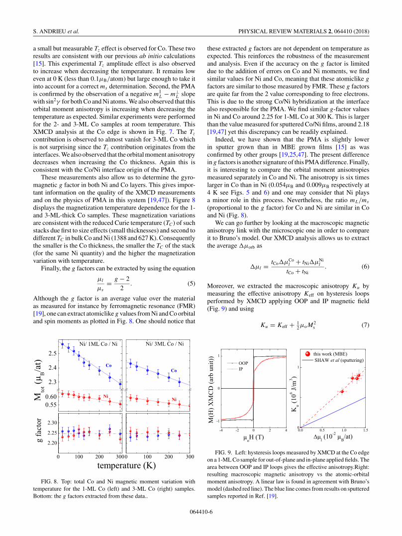
These measurements also allow us to determine the gyro-magnetic g factor in both Ni and Co layers. This gives impor-tant information on the quality of the XMCD measurementsand on the physics of PMA in this system [19,47]). Figure 8displays the magnetization temperature dependence for the 1-and 3-ML-thick Co samples. These magnetization variationsare consistent with the reduced Curie temperature (TC) of suchstacks due first to size effects (small thicknesses) and second todifferent TC in bulk Co and Ni (1388 and 627 K). Consequentlythe smaller is the Co thickness, the smaller the TC of the stack(for the same Ni quantity) and the higher the magnetizationvariation with temperature.
Finally, the g factors can be extracted by using the equation
μl
μs
= g − 2
2. (5)
Although the g factor is an average value over the materialas measured for instance by ferromagnetic resonance (FMR)[19], one can extract atomiclike g values from Ni and Co orbitaland spin moments as plotted in Fig. 8. One should notice that
FIG. 8. Top: total Co and Ni magnetic moment variation withtemperature for the 1-ML Co (left) and 3-ML Co (right) samples.Bottom: the g factors extracted from these data..
these extracted g factors are not dependent on temperature asexpected. This reinforces the robustness of the measurementand analysis. Even if the accuracy on the g factor is limiteddue to the addition of errors on Co and Ni moments, we findsimilar values for Ni and Co, meaning that these atomiclike g
factors are similar to those measured by FMR. These g factorsare quite far from the 2 value corresponding to free electrons.This is due to the strong Co/Ni hybridization at the interfacealso responsible for the PMA. We find similar g-factor valuesin Ni and Co around 2.25 for 1-ML Co at 300 K. This is largerthan the value measured for sputtered Co/Ni films, around 2.18[19,47] yet this discrepancy can be readily explained.
Indeed, we have shown that the PMA is slightly lowerin sputter grown than in MBE grown films [15] as wasconfirmed by other groups [19,25,47]. The present differencein g factors is another signature of this PMA difference. Finally,it is interesting to compare the orbital moment anisotropiesmeasured separately in Co and Ni. The anisotropy is six timeslarger in Co than in Ni (0.054μB and 0.009μB respectively at4 K see Figs. 5 and 6) and one may consider that Ni playsa minor role in this process. Nevertheless, the ratio mL/ms
(proportional to the g factor) for Co and Ni are similar in Coand Ni (Fig. 8).
We can go further by looking at the macroscopic magneticanisotropy link with the microscopic one in order to compareit to Bruno’s model. Our XMCD analysis allows us to extractthe average �μorb as
�μl = tCo�μCol + tNi�μNi
l
tCo + tNi. (6)
Moreover, we extracted the macroscopic anisotropy Ku bymeasuring the effective anisotropy Keff on hysteresis loopsperformed by XMCD applying OOP and IP magnetic field(Fig. 9) and using
Ku = Keff + 12μoM
2s (7)
FIG. 9. Left: hysteresis loops measured by XMCD at the Co edgeon a 1-ML Co sample for out-of-plane and in-plane applied fields. Thearea between OOP and IP loops gives the effective anisotropy.Right:resulting macroscopic magnetic anisotropy vs the atomic-orbitalmoment anisotropy. A linear law is found in agreement with Bruno’smodel (dashed red line). The blue line comes from results on sputteredsamples reported in Ref. [19].
064410-6

Co/Ni MULTILAYERS FOR SPINTRONICS: HIGH SPIN … PHYSICAL REVIEW MATERIALS 2, 064410 (2018)
According to Bruno’s model, these macroscopic and micro-scopic anisotropies are linked as [19,35]
Ku = AξN
4V
�μl
μB
, (8)
where N/V is the atomic density (close to 8.9 ×1028 atom/m3 here), ξ the spin-orbit coupling parameter (weuse the same value as in [19], ξ ≈ −1.6 × 10⁻²⁰ J/atom), μB
the Bohr magneton, and A is a prefactor found in the literatureto vary between 0.05 and 0.2 [41,47]. We report in Fig. 9 ourdata together with the results obtained on sputtered multilayersamples by Shaw’s group [19]. We also confirm Bruno’s lawbut interestingly, we obtained a slope A = 0.18 around twotimes larger than those obtained on sputtered samples.
IV. CRYSTALLINE ARRANGEMENT STUDIED BYSURFACE DIFFRACTION
The previously published disagreements obtained betweenab initio magnetic-moment calculations and the experimentalresults [15,25,33] motivated us to re-examine the crystallo-graphic ordering in Co/Ni superlattices. Previous calculationswere carried out by considering a perfect fcc stack of hexagonallattices, with distances between atoms similar or very close tothose of the bulk phases. On the one hand, the distance betweenthe Co and Ni planes at the interface may impact the electronicproperties if, for example, it is much different compared tobulk interplanar distance used in the calculations. Moreover, aparticular arrangement of the Co and Ni atoms at the interfacehas to be considered. To get such information, we performedsurface x-ray-diffraction experiments on Co films. We firstexamined Co films deposited on the Al2O3/V/Au/Ni(111)stack but in that case we increase the number of parametersin the fit of the truncation rods. We thus eliminated thiscomplexity by analyzing the Co structure when deposited ona single-crystalline Ni(111) substrate. We also examined Cofilms covered with a Ni ML.
In a surface diffraction experiment, the x-ray beam is sentat grazing incidence. The diffraction pattern consists in surfacetruncation rods perpendicular to the surface in the reciprocalspace. A surface diffraction experiment consists of measuringthese rods. Their profiles are extremely sensitive to variousfactors: atomic positions in the lattice, the type of atoms at eachsite, the stacking sequence, distances in the plane and out of theplane, and roughness [48–50]. These experiments generallyrequire the use of synchrotron radiation given the strongreduction of the signal compared to conventional diffractionsetup. Moreover, the energy choice using synchrotron radiationis mandatory in the present case since Ni and Co are neighborsin the periodic table so that their x-ray diffusion contrast is thenvery low using a regular x-ray-diffraction setup. One elegantway of overcoming this difficulty is to set the x-ray beamenergy at the 1s Co edge (hν = 7709 eV). The Co scatteringfactor is then strongly decreased by about 12 electrons whereasthat of Ni remains close to 26 electrons at this energy, thusensuring a high diffraction contrast to x rays (a procedure calledanomalous surface diffraction).
The experiments were carried out on the UHV diffractionstation of the SixS beamline at the SOLEIL synchrotron source.The samples were prepared in the preparation chamber hosted
FIG. 10. LEED patterns obtained on (a) the Ni(111) surface and(b) after the growth of 2-ML-thick Co film. The unit cell chosen forROD simulation is indicated in (c). Some truncation rods indexationis shown in (d). Six rods were measured for each sample.
by the diffractometer. The cleaning process of the substrate sur-face involved various cycles of Ar+ ion sputtering at 1 keV andsubsequent annealing to 1100 K. The cleanliness and surfacequality of the samples was checked by means of Auger electronspectroscopy and low-energy electron diffraction (LEED), re-spectively. Co was deposited using an e-beam evaporator. TheCo deposition rate was calibrated using a quartz microbalancelocated at the place of the sample. Co was deposited at roomtemperature (to avoid intermixing) at a rate of 1 ML/min. Foreach sample the Ni(111) substrate was reprepared followingthe above-mentioned procedure. Figures 10(a) and 10(b) showthe LEED pattern measured for the clean Ni(111) surface andafter the Co deposition, respectively. Six different sampleswere prepared and analyzed: the bare Ni(111) substrate, x MLCo /Ni(111)substrate with x = 1, 2, and 3, and 1 ML Ni/x MLCo/Ni(111) with x = 1 and 2.
The x-ray-diffraction data presented in this paper are in-dexed according to the surface unit cell of Ni(111) described bythe following parameters: a = b = 0.2489 nm, c = 0.609 nmand α = β = 90◦, γ = 120◦. Indeed, since Co can be grown infcc (ABCABC stacking sequence) or in hcp (ABAB stacking),at least four planes stacked along (111) were considered toaccount for these two possible types of stacking [Fig. 10(c)].A schematic view of the reciprocal space is represented inFig. 10(d). For each sample we measured the integrated inten-sities along six crystal truncation rods on each sample: (11L),(1 – 2L), (−10L), (1 – 1L), (−11L), (0 – 1L) with L varyingfrom 0.1 to 2.4 (larger values of L were not achievable due togeometric constraints). This gives three series of nonequivalent
064410-7

S. ANDRIEU et al. PHYSICAL REVIEW MATERIALS 2, 064410 (2018)
FIG. 11. Experimental structure factors (blue open circles, to-gether with error bars) and the best-fit structure factors (solid redline) truncations rods and simulation for the six samples, from top tobottom: Ni(111) substrate, Ni + 1-ML Co, Ni + 1-ML Co+ 1-MLNi, Ni + 2-ML Co, Ni + 2-ML Co + 1-ML Ni, Ni + 3-ML Co. Theschematic representation of the models of stacks obtained after ROD
simulations is shown on the right.
truncation rods along (Fig. 10)(i) (11L), (1 – 2L) – Bragg peak at L = 0,(ii) (−10L),(1 – 1L) – Bragg peak at L = 1,(iii) (−11L), (0 – 1L) – Bragg peak at L = 2.After background subtraction and application of standard
correction factors a fit of the data was carried out using thesoftware package ROD [51].
A detailed structural refinement was performed by fittingsimultaneously three nonequivalent truncation rods. The ex-perimental (blue circles) together with the best fit (red curve)structure factors are shown in Fig. 11. During the refinement,the existence of two domains with different stacks had to beconsidered, whose percentages are also given on the right-handside of Fig. 11. It should be noted that in all the simulationsthe extracted roughness was found very close to zero (thesimulations are shown for a roughness equal to zero). For theNi substrate, during the refinement the only variable is theout-of-plane relaxation of the topmost plane. The simulationsare excellent and almost no surface relaxation is observed(<1%) in agreement with the literature [52].
For the 1-ML Co film, the nucleation site of the Co layermust be taken into account during the refinement. Consideringthe ABC stacking of the Ni substrate by terminating with a Cplane, several options may be considered for Co nucleation: thenucleation site (A, B, or C) is left free for both domains. Theresults of the refinement show that the site C is not occupiedand that sites A (domain 1) and B (domain 2) can be occupiedwith some preference for site A. The fit also shows that the Cofilm thickness is not exactly 1 ML but 1.2 MLs, which is withinthe error bar of the thickness control on this setup. Thereforea second plane has grown on the first monolayer. Two types ofstacking are obtained corresponding to 70% as an extension ofthe fcc structure of Ni and to 30% as a hcp stacking. When thistype of deposit is covered with 1 ML of Ni, the fcc stacking isthen favored representing 90% of the surface.
The situation changes drastically for Co thickness higherthan 1 ML. For 2 MLs thick, the Co film adopts preferentiallythe hcp structure (domain 1, 70%), even if there remain zoneswith an fcc stacking (domain 2, 30%). For 3-ML Co, the hcpstacking dominates and no more fcc stacking occurs. The Nicapping no longer affects the stacking of the Co which remainshcp, contrary to the previous case with a single plane of Co.Finally, the interplanar distances for all these samples obtainedfollowing the data refinements are found very close to the bulkNi atomic distance. The out-of-plane relaxations never exceed+/− 3%, which is of the order of magnitude of the misfitbetween Co and Ni bulk lattices.
Therefore this analysis clearly demonstrates that there is nospecial atomic arrangement other than the fcc or hcp stacking,and no strong lattice parameter relaxation. The only parameterthat changes from one sample to another is the stackingsequence. For 1-ML Co film the fcc stacking is preferred, butthe hcp stacking dominates for Co films thicker than 2 MLs.This means that an atomic plane of Co needs to be covered byCo to generate the hcp structure.
V. AB INITIO CALCULATIONS
In the previous section, we finally observed that many Costacks on Ni between fcc and hcp may occur. Up to now the abinitio calculations were performed only considering a fcc stackin the whole superlattice [22]. The electronic structure of theNi(3 ML) /Co(2 ML) superlattices with different stacking ofthe Ni and Co monolayers have thus been calculated from firstprinciples, using the code WIEN2K [53] and the Perdew-Burke-Ernzerhof (PBE) [54] functional for describing the exchangeand correlation potential. We used atomic spheres with a radius
064410-8

Co/Ni MULTILAYERS FOR SPINTRONICS: HIGH SPIN … PHYSICAL REVIEW MATERIALS 2, 064410 (2018)
TABLE I. Calculated spin magnetic moment of Ni and Co atoms at the interfaces and of Ni atoms at the center of the Ni layers in Ni(3ML)/Co(2 ML) superlattices with different stacking sequences. The averaged value of the nickel spin atomic moment is also given. In the lastline are reported the experimental spin moments of a 1-ML Co in between Ni at 10 K given by XMCD.
Theoretical spin magnetic moment (Bohr magneton)
Ni Ni NiSuperlattices stacking interface central average Co
Ni(fcc)/Co(fcc) 0.6784 0.6387 0.6651 1.7426Ni(fcc)/Co(hcp)1 0.6994 0.5997 0.6662 1.7423Ni(fcc)/Co(hcp)2 0.6983 0.6174 0.6713 1.7493Ni(fcc)/Co(hcp) 0.7091 0.6289 0.6824 1.7510
Expt.μspin 10 K 0.55 2.28
of 0.1164 nm (2.2 atomic units), an in-plane lattice parameterof 0.2507 nm, and a distance of 0.2047 nm between successiveatomic layers (measured on our samples [15]). We consideredfour different stackings, which differ by the sequences of thesuccessive Ni and Co monolayers occupying the conventionalA, B, or C atomic sites of the fcc lattice. The four superlatticesthat we studied correspond to the following:
(i) a perfect fcc stacking, labeled “Ni(fcc)/Co(fcc)," withthe sequence Ni(ABC)/Co(AB)/Ni(CAB)/Co(CA)/Ni(BCA)/Co(BC),
(ii) a first stacking combining fcc Ni and hcp Co, labeled“Ni(fcc)/Co(hcp)1,” with the sequence Ni(ABC)/Co(BC)/Ni(BCA)/Co(CA)/Ni(CAB)/Co(AB),
(iii) a second stacking combining fcc Ni and hcp Co,labeled “Ni(fcc)/Co(hcp)2,” with the sequence Ni(ABC)/Co(AC),
(iv) finally a perfect hcp stacking, labeled “Ni(hcp)/Co(hcp),” with the sequence Ni(ABA)/Co(BA)/Ni(BAB)/Co(AB).
The spin magnetic moments that we calculated for thedifferent atoms in these SLs are given in Table I. To summarize,the stacking sequence has a small influence on the averagednickel magnetic moment and on the Co spin magnetic moment,which only vary by 2.6% and 0.5%, respectively. Finally, wealso varied the distance at the interface between Co and Niup to 5% and the Co atomic moment was observed to varyinsignificantly compared to our observations.
VI. DISCUSSION
The first point we want to address concerns the link betweenmacroscopic anisotropy via Ku and microscopic anisotropyvia �ml (Sec. III B, Fig. 9). The agreement with Bruno’smodel is quite comparable to that observed in other epitaxialsystems. However, this law is not similar for epitaxial Co/Nisuperlattices (MBE) or for multilayers (sputtering). This ob-servation is not surprising since at least four different groups[15,19,25,47] came to the same conclusion: the macroscopicmagnetic anisotropy Ku is higher in epitaxial films. However,the anisotropy on the atomic-orbital moment (�ml) observedhere is similar to the values reported by Shaw and co-workers[19]. This strongly suggests that the origin of the Ku differenceobtained between epitaxial and sputtered samples does notoccur at the atomic level but on a larger scale (possiblyroughness or small impurities concentration).
Concerning the atomic magnetic moments (Sec. III B), thespin moment of Ni is therefore close to the bulk value, whereasa noticeable increase of the orbital moment is observed herecompared to the bulk. The situation is more complex for Co.The previous XMCD results [15] indicate that two differentsites (and only two) need to be considered in the stack of Colayers. At the interface with Ni, the two contributions of spinand orbit are strongly increased with respect to bulk (hcp or fcc)Co values. On the other hand, for the Co atoms surrounded byCo (the central plane for a layer of three planes for example),the measured moments are then comparable to the bulk values.The strong increase of the Co moments at the interface withNi had previously been discussed [15] as possibly comingfrom the application of the sum rules in particular for thespin moment determination. Indeed, the contribution of Tz
(which can strongly increase at a symmetry-breaking interface)could affect the estimation of the spin moment. In this study,it was possible to determine experimentally this contribution.We find it to be low even if it is not negligible. The “true”values of the spin moments were thus determined. However,they are still increased by about 30% compared to a wholeCo environment, whereas a 6% increase is given by thecalculations considering a perfect fcc structure of superlattices[15]. We have therefore carried out calculations by consideringan hcp stack of Co (Sec. V, Table I). The results remainunchanged. Finally, we have varied in the calculations thedistances between the plane of Co at the interface with Niand in the Co layers of several %, in any case beyond whatwe determined using anomalous surface diffraction. Again,we did not get any increase in Co moments as observedexperimentally.
Consequently, there is a significant disagreement betweenthe Co moments determined experimentally and the calculatedones by considering a crystallographic structure in agreementwith the observation given by diffraction. This disagreementis surprising since a very simple model gives a qualitativeexplanation for the observations. Indeed, one can consider onthe one hand that at the interface Co and Ni exchange electronsin such a way that the 3d band of Co is filled with 7.5 electrons[15,33]. On the other hand, if we consider that the 3d bandof the majority electrons is completely filled at the interface,there remain 2.5 electrons in the minority band. This scenariothen leads to a full spin polarization and to an atomic momentof 2.5μB for Co at the interface with Ni, in agreement with theexperiment.
064410-9
S. ANDRIEU et al. PHYSICAL REVIEW MATERIALS 2, 064410 (2018)
VII. CONCLUSION
In this paper, we show that very high spin polarization isobtained in Co/Ni(111) superlattices, a 3d metals based sys-tem. We also brought another experimental proof that the PMAin Co/Ni superlattices is closely linked to the Co/Ni interface.Interestingly, the effective magnetic anisotropy can be tunedby controlling the Ni coverage on a Co film. Such a possibilitymay be an opportunity for switching the magnetization by anexternal electric field (in a tunnel barrier for instance), usingan adequate Ni coverage to get the system very close to the in-plane to out-of-plane transition. The angle-dependent XMCDanalysis using strong field and low temperature allowed usto confirm the very high magnetic moment of Co in contactwith Ni (2.55μB to be compared to the bulk value 1.7μB).Such a strong enhancement has still to be reproduced using abinitio calculations but our surface diffraction results drasticallylimit the number of configurations that have to be considered.The anisotropy of the orbital magnetic moment is shown to belinked to the magnetocrystalline anisotropy following Bruno’smodel. As a consequence, the much stronger orbital momentanisotropy in Co compared to Ni demonstrates that PMA isessentially due to Co. This analysis also sheds some light on the
PMA difference observed in sputtered and MBE-grown sam-ples. The anisotropy at the atomic level (�μl) are similar usingboth growth techniques, whereas the macroscopic anisotropy(Ku) is lower on sputtered films. This strongly suggests thatthe origin of this magnetic anisotropy difference is not at theatomic level but on a large scale. Finally, these results, Cotermination to get high SP and number of Co/Ni interfacesto get PMA, have to be taken into account when defining thearchitecture of a device. This is an example of approachingfull spin polarization by exploiting ultrathin transition metallayers and opens interesting directions engineering spintronicmaterials.
ACKNOWLEDGMENTS
This work was supported partly by the French PIAproject “Lorraine Université d’Excellence,” reference ANR-15-IDEX-04-LUE. The theoretical calculations were grantedaccess to the HPC resources of CALMIP supercomputingcenter under the allocation P1252. We acknowledge E. E.Fullerton from the Center for Memory and Recording Research(University of California San Diego) for his critical reading ofthe manuscript.
[1] J. C. Sankey, Y.-T. Cui, J. Z. Sun, J. C. Slonczewski, R. A.Buhrman, and D. C. Ralph, Measurement of the spin-transfer-torque vector in magnetic tunnel junctions, Nat. Phys. 4, 67(2007).
[2] J. S. Meena, M. S. Simon, C. Umesh, and T-Y Tseng, Overviewof emerging nonvolatile memory technologies, Nanoscale Res.Lett. 9, 526 (2014).
[3] T. Silva and W. Rippard, Developments in nano-oscillators basedupon spin-transfer point-contact devices, J. Magn. Magn. Mater.320, 1260 (2010).
[4] K. Dumesnil and S. Andrieu, Molecular Beam Epitaxy: FromQuantum Wells to Quantum Dots. From Research to MassProduction Chap 20: Epitaxial Magnetic Layers Grown byMBE: Model Systems to Study the Physics in Nanomagnetismand Spintronic, edited by M. Henini (Elsevier, New York, 2012).
[5] M. T. Johnson, P. J. H Bloemen, F. J. A den Broeder, and J. J. deVries, Magnetic anisotropy in metallic multilayers, Rep. Prog.Phys. 59, 1409 (1996).
[6] G. Andersson, T. Burkert, P. Warnicke, M. Björck, B. Sanyal, C.Chacon, C. Zlotea, L. Nordström, P. Nordblad, and O. Eriksson,Perpendicular Magnetocrystalline Anisotropy in Tetrago-nallyDistorted Fe-Co Alloys, Phys. Rev. Lett. 96, 037205 (2006).
[7] S. Ouazi, S. Vlaic, S. Rusponi, G. Moulas, P. Buluschek, K.Halleux, S. Bornemann, S. Mankovsky, J. Minar, J. B. Staunton,H. Ebert, and H. Brune, Atomic-scale engineering of magneticanisotropy of nanostructures through interfaces and interlines,Nat. Commun. 3, 1313 (2012).
[8] A. Rajanikanth, S. Kasai, N. Ohshima, and K. Ohno, Spinpolarization of currents in Co/Pt multilayer and Co–Pt alloy thinfilms, Appl. Phys. Lett. 97, 022505 (2010).
[9] Y. Sakuraba, M. Hattori, M. Oogane, Y. Ando, H. Kato,A. Sakkuma, T. Miyazaki, and H. Kubota, Giant tunneling
magnetoresistance in Co2Mn Si/Al–O/Co2MnSi magnetic tun-nel junctions, Appl. Phys. Lett. 88, 192508 (2006).
[10] T. Marukame, T. Ishikawa, K. Matsuda, T. Uemura, and M. Ya-mamoto, High tunnel magnetoresistance in fully epitaxial mag-netic tunnel junctions with a full-Heusler alloy Co2Cr0.6Fe0.4Althin film, Appl. Phys. Lett. 88, 262503 (2006).
[11] N. Tezuka, N. Ikeda, S. Sugimoto, and K. Inomata, 175% tunnelmagnetoresistance at room temperature & high thermal stabilityusing Co2FeAl0.5Si0.5 full-Heusler alloy electrodes, Appl. Phys.Lett. 89, 252508 (2006).
[12] S. Andrieu, A. Neggache, T. Hauet, T. Devolder, A. Hallal,M. Chshiev, A. M. Bataille, P. Le Fevre, and F. Bertran,Direct evidence for minority spin gap in the Co2MnSi Heuslercompound, Phys. Rev. B 93, 094417 (2016).
[13] B. Pradines, R. Arras, I. Abdallah, N. Biziere, and L. Calmels,First-principles calculation of the effects of partial alloy disorderon the static and dynamic magnetic properties of Co2MnSi, Phys.Rev. B 95, 094425 (2017).
[14] L. You, R. C. Sousa, S. Bandiera, B. Rodmacq, and B. Dieny,Co/Ni multilayers with perpendicular anisotropy for spintronicdevice applications, Appl. Phys. Lett. 100, 172411 (2012).
[15] M. Gottwald, S. Andrieu, F. Gimbert, E. Shipton, L. Calmels,C. Magen, E. Snoeck, M. Liberati, T. Hauet, E. Arenholz, S.Mangin, and E. E. Fullerton, Co/Ni(111) superlattices studied bymicroscopy, X-ray absorption and ab-initio calculations, Phys.Rev. B 86, 014425 (2012).
[16] M. T. Johnson, J. J. de Vries, N. W. E. McGee, J. aan deStegge, and F. J. A. den Broeder, Orientational Dependence ofthe Interface Magnetic Anisotropy in Epitaxial Ni/Co/Ni, Phys.Rev. Lett. 69, 3575 (1992).
[17] Y. B. Zhang, J. A. Woollam, Z. S. Shan, J. X. Shen, andD. J. Sellmyer, Anisotropy and magneto-optical properties of
064410-10

Co/Ni MULTILAYERS FOR SPINTRONICS: HIGH SPIN … PHYSICAL REVIEW MATERIALS 2, 064410 (2018)
sputtered Co/Ni multilayer thin films, IEEE Trans. Magn. 30,4440 (1994).
[18] S. Girod, M. Gottwald, S. Andrieu, S. Mangin, J. McCord, EricE. Fullerton, J.-M. L. Beaujour, B. J. Krishnatreya, and A. D.Kent, Strong perpendicular magnetic anisotropy in Ni/Co(111)single crystal superlattices, Appl. Phys. Lett. 94, 262504 (2009).
[19] J. M. Shaw, H. T. Nembach, and T. J. Silva, Measurement oforbital asymmetry and strain in Co90Fe10/Ni multilayers andalloys: Origins of perpendicular anisotropy, Phys. Rev. B 87,054416 (2013).
[20] G. H. O. Daalderop, P. J. Kelly, and F. J. A. den Broeder, Predic-tion and Confirmation of Perpendicular Magnetic Anisotropy inCo/Ni Multilayers, Phys. Rev. Lett. 68, 682 (1992).
[21] K. Kyuno, J. G. Ha, R. Yamamoto, and S. Asano, Perpendicularmagnetic anisotropy of metallic multilayers composed of mag-netic layers only/ Ni/Co and Ni/Fe multilayers, Jpn. J. Appl.Phys. 35, 2774 (1996).
[22] F. Gimbert and L. Calmels, First-principles investigation of themagnetic anisotropy and magnetic properties of Co/Ni(111)superlattices, Phys. Rev. B 86, 184407 (2012).
[23] J.-M. Beaujour, W. Chen, K. Krycka, C.-C. Kao, J. Z. Sun, andA. D. Kent, Ferromagnetic resonance study of sputtered Co|Nimultilayers, Eur. Phys. J. B 59, 475 (2007).
[24] W. Chen, J.-M. L. Beaujour, G. deLoubens, and A. D. Kent,Spin-torque driven ferromagnetic resonance of Co/Ni syntheticlayers in spin valves, Appl. Phys. Lett. 92, 012507 (2008).
[25] T. Seki, J. Shimada, S. Iihama, M. Tsujikawa, T. Koganezawa,A. Shioda, T. Tashiro, W. Zhou, S. Mizukami, M. Shirai, and K.Takanashi, Magnetic anisotropy and damping for monolayer-controlled Co|Ni epitaxial multilayer, J. Phys. Soc. Jpn. 86,074710 (2017).
[26] S. Mangin, D. Ravelosona, J. A. Katine, M. J. Carey, B. D. Terris,and E. E. Fullerton, Current-induced magnetization reversal innanopillars with perpendicular anisotropy, Nat. Mater. 5, 210(2006).
[27] S. Mangin, Y. Henry, D. Raveloson, J. A. Katine, and E.E. Fullerton, Reducing the critical current for spin-transferswitching of perpendicularly magnetized nanomagnets, Appl.Phys. Lett. 94, 012502 (2009).
[28] D. P. Bernstein, B. Bräuer, R. Kukreja, J. Stöhr, T. Hauet, J.Cucchiara, S Mangin, J. A. Katine, T. Tyliszczak, K. W. Chou,and Y. Acremann, Nonuniform switching of the perpendicularmagnetization in a spin-torque-driven magnetic nanopillar, Phys.Rev. B 83, 180410(R) (2011).
[29] H. Tanigawa, T. Koyama, G. Yamada, D. Chiba, S. Kasai,S. Fukami, T. Suzuki, N. Ohshima, and N. Ishiwata, Domainwall motion induced by electric current in a perpendicularlymagnetized Co/Ni nano-wire, Appl. Phys. Express 2, 053002(2009).
[30] K. Ueda, T. Koyoma, R. Hiramatsu, D. Chiba, S. Fukami, H.Tanigawa, T. Suzuki, N. Ohshima, N. Ishiwata, Y. Nakatani,K. Kobayashi, and T. Ono, Temperature dependence of carrierspin polarization determined from current-induced domain wallmotion in a Co/Ni nanowire, Appl. Phys. Lett. 100, 202407(2012).
[31] S. Legal, N. Vernier, F. Montaigne, M. Gottwald, D. Lacour, M.Hehn, J. McCord, D. Ravelosona, S. Mangin, S. Andrieu, and T.Hauet, Thermally activated domain wall motion in [Co/Ni](111)superlattices with perpendicular magnetic anisotropy, Appl.Phys. Lett. 106, 062406 (2015).
[32] S. Le Gall, N. Vernier, F. Montaigne, A. Thiaville, J. Sampaio,D. Ravelosona, S. Mangin, S. Andrieu, and T. Hauet, Effect ofspin transfer torque on domain wall motion regimes in [Co/Ni]superlattice wires, Phys. Rev. B 95, 184419 (2017).
[33] F. Gimbert, L. Calmels, and S. Andrieu, Localized electron states& spin polarization in Co/Ni(111) overlayers, Phys. Rev. B 84,094432 (2011).
[34] Ia. Lytvynenko, C. Deranlot, S. Andrieu, and T. Hauet, Mag-netic tunnel junctions using Co/Ni multilayer electrodes withperpendicular magnetic anisotropy, J. Appl. Phys. 117, 053906(2015).
[35] M. Arora, R. Hübner, D. Suess, B. Heinrich, and E. Girt, Originor perpendicular magnetic anisotropy in Co/Ni multilayers,Phys. Rev. B 96, 024401 (2017).
[36] P. Bruno, Tight-binding approach to the orbital magnetic mo-ment and magnetocrystalline anisotropy of transition-metalmonolayers, Phys. Rev. B 39, 865 (1989).
[37] S. Andrieu, L. Calmels, T. Hauet, F. Bonell, P. Le Fevre, and F.Bertran, Spectroscopic & transport studies of CoxFe1−x/MgObased MTJs, Phys. Rev. B 90, 214406 (2014).
[38] Y. Kamada, H. Kasai, T. Kingetsu, and M. Yamamoto, Structure& magnetic properties of Au/Ni/Ag & Ag/Ni/Au superlattices,J. Magn. Soc. Jpn. 23, 581 (1999).
[39] J. Stöhr and H. König, Determination of Spin- and Orbital-Moment Anisotropies in Transition Metals by Angle-DependentX-Ray Magnetic Circular Dichroism, Phys. Rev. Lett. 75, 3748(1995).
[40] P. Ohresser, E. Otero, F. Choueikani, K. Chen, S. Stanescu, F.Deschamps, T. Moreno, F. Polack, B. Lagarde, J-P. Daguerre,F. Marteau, F. Scheurer, L. Joly, J.-P. Kappler, B. Muller, O.Bunau, and P. Sainctavit, DEIMOS: A beamline dedicated todichroism measurements in the 350–2500 eV energy range, Rev.Sci. Instrum. 85, 013106 (2014).
[41] L. Joly, E. Otero, F. Choueikani, F. Marteau, L. Chapuis, and P.Ohresser, Fast continuous energy scan with dynamic couplingof the monochromator and undulator at the DEIMOS beamline,J. Synchrotron Radiat. 21, 502 (2014).
[42] F. Wilhelm, P. Poulopoulos, P. Srivastava, H. Wende, M.Farle, K. Baberschke, M. Angelakeris, N. K. Flevaris, W.Grange, J.-P. Kappler, G. Ghiringhelli, and N. B. Brookes,Magnetic anisotropy energy and the anisotropy of the orbitalmoment of Ni in Ni/Pt multilayers, Phys. Rev. B 61, 8647(2000).
[43] R. Nakajima, J. Stohr, and Y. U. Idzerda, Electron-yield satura-tion effects in L-edge x-ray magnetic circular dichroism spectraof Fe, Co, and Ni, Phys. Rev. B 59, 6421 (1999).
[44] M. Sicot, S. Andrieu, F. Bertran, and F. Fortuna, Electronicproperties of Fe, Co, and Mn ultrathin films at the interface withMgO(001), Phys. Rev. B 72, 144414 (2005).
[45] G. van der Laan, Microscopic origin of magneto-crystallineanisotropy in transition metal thin films, J. Phys.: Condens.Matter 10, 3239 (1998).
[46] H. A. Dürr and G. van der Laan, Magnetic circular x-raydichroism in transverse geometry: Importance of noncollinearground state moments, Phys. Rev. B 54, R760 (1996).
[47] D. Weller, J. Stohr, R. Nakajima, A. Carl, M. G. Samant,C. Chappert, R. Megy, P. Beauvillain, P. Veillet, and G. A.Held, Microscopic Origin of Magnetic Anisotropy in Au/Co/AuProbed with X-Ray Magnetic Circular Dichroism, Phys. Rev.Lett. 75, 3752 (1995).
064410-11

S. ANDRIEU et al. PHYSICAL REVIEW MATERIALS 2, 064410 (2018)
[48] R. Feidenhans’l, Surface structure determination by X-raydiffraction, Surf. Sci. Rep. 10, 105 (1989).
[49] I. K. Robinson, Surface Crystallography, Handbook on Syn-chrotron Radiation Chap. 7, edited by G. Brown and D. E.Moncton (North-Holland, Amsterdam, 1991), Vol. 3.
[50] G. Renaud, Oxide surfaces and metal/oxide interfaces studied bygrazing incidence X-ray scattering, Surf. Sci. Rep. 32, 1 (1998).
[51] E. Vlieg, ROD, a program for surface X-ray crystallography, J.Appl. Crystallogr. 33, 401 (2000).
[52] J. Wan, Y. L. Fan, D. W. Gong, S. G. Shen, and X. Q. Fan, Surfacerelaxation and stress of fcc metals: Cu, Ag, Au, Ni, Pd, Pt, Aland Pb, Modell. Simul. Mater. Sci. Eng. 7, 189 (1999).
[53] P. Blaha, K. Schwarz, P. Sorentin, and S. B. Trickey, Full-potential, linearized augmented plane wave programs for crys-talline systems, Comput. Phys. Commun. 59, 399 (1990).
[54] J. P. Perdew, K. Burke, and M. Ernzerhof, Generalized Gra-dient Approximation Made Simple, Phys. Rev. Lett. 77, 3865(1996).
064410-12