Analysis of Coil Parameters and Comparison of ... - MDPI
25
Article Analysis of Coil Parameters and Comparison of Circular, Rectangular, and Hexagonal Coils Used in WPT System for Electric Vehicle Charging Tasnime Bouanou *, Hassan El Fadil, Abdellah Lassioui, Ouidad Assaddiki and Sara Njili Citation: Bouanou, T.; El Fadil, H.; Lassioui, A.; Assaddiki, O.; Njili, S. Analysis of Coil Parameters and Comparison of Circular, Rectangular, and Hexagonal Coils Used in WPT System for Electric Vehicle Charging. World Electr. Veh. J. 2021, 12, 45. https://doi.org/10.3390/ wevj12010045 Received: 7 January 2021 Accepted: 13 March 2021 Published: 17 March 2021 Publisher’s Note: MDPI stays neutral with regard to jurisdictional claims in published maps and institutional affil- iations. Copyright: © 2021 by the authors. Licensee MDPI, Basel, Switzerland. This article is an open access article distributed under the terms and conditions of the Creative Commons Attribution (CC BY) license (https:// creativecommons.org/licenses/by/ 4.0/). Ingénierie des Systèmes Avancés (ISA) Laboratory, ENSA, Ibn Tofail University, Kenitra BP 242, Morocco; [email protected] (H.E.F.); [email protected] (A.L.); [email protected] (O.A.); [email protected] (S.N.) * Correspondence: [email protected] Abstract: In this paper, the major factors that affect the performance of wireless power transfer systems, such as coil inner radius and coil number of turns, are discussed. A comparison of three coil shapes covering the coreless case, the case with ferrite, and the case with ferrite and aluminum is also carried out. Another comparison is proposed by addressing the combination of different coil shapes in the wireless power transfer (WPT)system. The analysis covers the coupling coefficient, the mutual inductance, and the self-inductance. Due to the complexity of calculating these parameters, the finite element analysis (FEA) method is adopted by using the Ansys Maxwell software. An introduction to the typical WPT system for electric vehicle charging is also presented. Keywords: electric vehicle (EV); wireless power transfer (WPT); magnetic resonant WPT; finite element analysis (FEA); coupling coefficient; shielding; mutual inductance; self-inductance; An- sys Maxwell 1. Introduction As the large demand for fossil fuels for road transportation continues to grow and the percentage of pollution coming from conventional vehicles increases, the need for an alternative solution has become a major necessity. The electric vehicle presents a suitable solution for road transportation by offering multiple advantages: zero gas emissions, reduced noise pollution, low maintenance, and lower running costs [1]. The biggest challenge that electric vehicles face is the battery pack capacities, which give a short driving range because of their limited life and high cost [2]; currently, the battery charging operation for the electric vehicle is carried out by the charging cables. On the other hand, the wireless power transfer system charging method is already used in a variety of systems and applications, such as biomedical devices, industrial manufacturing, including robotic platforms, and a few consumer electronics (watches, smartphones, etc.) [3]. The magnetic resonant wireless power transfer (WPT) technology is a method pro- posed by Kurs [4] where the energy is wirelessly transferred between the transmitting coil and the secondary coil under resonant conditions. It is suitable for electric vehicle applications. The electric vehicle wireless charging operation is carried out in stationary or dynamic mode. In the first mode, the vehicle is parked whereby the transmitting coil is parallel to the receiving coil. Then, the charging operation can be started. In the second mode, the vehicle is charged while moving on the road occupied by transmitting coils. Thereby, the wireless charging method is easier, with no need for human intervention, safer, and needs less maintenance compared to the conductive method. However, the wireless charging method presents some drawbacks—for example, the large distance between the transmitting and receiving coil, resulting in low coupling and human safety due to the exposure to the magnetic field. The coil design is one of the crucial factors in designing World Electr. Veh. J. 2021, 12, 45. https://doi.org/10.3390/wevj12010045 https://www.mdpi.com/journal/wevj
-
Upload
khangminh22 -
Category
Documents
-
view
4 -
download
0
Transcript of Analysis of Coil Parameters and Comparison of ... - MDPI
Article
Analysis of Coil Parameters and Comparison of Circular,Rectangular, and Hexagonal Coils Used in WPT System forElectric Vehicle Charging
Tasnime Bouanou *, Hassan El Fadil, Abdellah Lassioui, Ouidad Assaddiki and Sara Njili
�����������������
Citation: Bouanou, T.; El Fadil, H.;
Lassioui, A.; Assaddiki, O.; Njili, S.
Analysis of Coil Parameters and
Comparison of Circular, Rectangular,
and Hexagonal Coils Used in WPT
System for Electric Vehicle Charging.
World Electr. Veh. J. 2021, 12, 45.
https://doi.org/10.3390/
wevj12010045
Received: 7 January 2021
Accepted: 13 March 2021
Published: 17 March 2021
Publisher’s Note: MDPI stays neutral
with regard to jurisdictional claims in
published maps and institutional affil-
iations.
Copyright: © 2021 by the authors.
Licensee MDPI, Basel, Switzerland.
This article is an open access article
distributed under the terms and
conditions of the Creative Commons
Attribution (CC BY) license (https://
creativecommons.org/licenses/by/
4.0/).
Ingénierie des Systèmes Avancés (ISA) Laboratory, ENSA, Ibn Tofail University, Kenitra BP 242, Morocco;[email protected] (H.E.F.); [email protected] (A.L.); [email protected] (O.A.);[email protected] (S.N.)* Correspondence: [email protected]
Abstract: In this paper, the major factors that affect the performance of wireless power transfersystems, such as coil inner radius and coil number of turns, are discussed. A comparison of three coilshapes covering the coreless case, the case with ferrite, and the case with ferrite and aluminum is alsocarried out. Another comparison is proposed by addressing the combination of different coil shapesin the wireless power transfer (WPT)system. The analysis covers the coupling coefficient, the mutualinductance, and the self-inductance. Due to the complexity of calculating these parameters, the finiteelement analysis (FEA) method is adopted by using the Ansys Maxwell software. An introduction tothe typical WPT system for electric vehicle charging is also presented.
Keywords: electric vehicle (EV); wireless power transfer (WPT); magnetic resonant WPT; finiteelement analysis (FEA); coupling coefficient; shielding; mutual inductance; self-inductance; An-sys Maxwell
1. Introduction
As the large demand for fossil fuels for road transportation continues to grow andthe percentage of pollution coming from conventional vehicles increases, the need for analternative solution has become a major necessity. The electric vehicle presents a suitablesolution for road transportation by offering multiple advantages: zero gas emissions,reduced noise pollution, low maintenance, and lower running costs [1].
The biggest challenge that electric vehicles face is the battery pack capacities, whichgive a short driving range because of their limited life and high cost [2]; currently, the batterycharging operation for the electric vehicle is carried out by the charging cables. On the otherhand, the wireless power transfer system charging method is already used in a variety ofsystems and applications, such as biomedical devices, industrial manufacturing, includingrobotic platforms, and a few consumer electronics (watches, smartphones, etc.) [3].
The magnetic resonant wireless power transfer (WPT) technology is a method pro-posed by Kurs [4] where the energy is wirelessly transferred between the transmittingcoil and the secondary coil under resonant conditions. It is suitable for electric vehicleapplications. The electric vehicle wireless charging operation is carried out in stationary ordynamic mode. In the first mode, the vehicle is parked whereby the transmitting coil isparallel to the receiving coil. Then, the charging operation can be started. In the secondmode, the vehicle is charged while moving on the road occupied by transmitting coils.Thereby, the wireless charging method is easier, with no need for human intervention, safer,and needs less maintenance compared to the conductive method. However, the wirelesscharging method presents some drawbacks—for example, the large distance between thetransmitting and receiving coil, resulting in low coupling and human safety due to theexposure to the magnetic field. The coil design is one of the crucial factors in designing
World Electr. Veh. J. 2021, 12, 45. https://doi.org/10.3390/wevj12010045 https://www.mdpi.com/journal/wevj

World Electr. Veh. J. 2021, 12, 45 2 of 25
a wireless charging system. The coil system in the stationary charging mode is designedin pad form. Several coil shapes are proposed in the literature. Circular and rectangularshapes are the most common structures used in electric vehicle (EV) chargers due to theirsimplicity. Furthermore, Auckland University [5] proposed a DD coil structure. In addition,other structures have been proposed, such as flux pipe couplers [6], DD-Q derived fromDD, bipolar pads [7], Tripolar pads, and more [8,9]. The design of the pad is a crucialexercise during the charger design process; the system is required to have a large air gap,misalignment tolerance, high coupling and efficiency, and light weight. The objective is toincrease the coupling and efficiency and reduce the leakage flux between the transmittingand receiving pads. The coil parameters have a significant effect on the performance ofthe coil; this effect includes the coupling coefficient, the mutual inductance, and the coilinductance. Moreover, ferrite and aluminum are usually used to guide the flux and reducethe leakage flux, respectively. Although the introduction of these materials enhances thecoupling values, the pad weight remains a crucial element during the pad conception.
The influence of the coil’s number of turns and the coil’s inner radius variation onsystem coupling is investigated in [10]. The simulation results of the coupling coefficientwere collected by varying the number of turns of the transmitting coil. The same resultswere collected for the coil inner radius. However, the study did not take into account thevariation in the receiving coil parameters and the simulation results of the coil inductanceand mutual inductance. In [11], a comparison between three coil shapes was carried out,using the same frequency; the simulation results of helix, planar spiral, and square helixcoils indicate that the helix coil has the highest efficiency while the planar spiral has thelowest one. However, the flat coil is the most widely adopted for electric vehicle chargingapplications in order to reduce the pad thickness. In [12], a comparison between the popularcoil shapes and the effects of coil parameters such as the number of turns, pitch, and innerand outer diameter on the efficiency of the coil is conducted. However, no simulations havebeen conducted to analyze these parameters and to perform a comparison between coils.In [13], a simulation study was carried out to explore the variation in the coupling coefficientfor different coil shapes under different air gaps and coil misalignments. However, thevariation in the coil inductance was not discussed. In the same context, [14] presents a cost-effectiveness comparison of three shapes—rectangular, circular, and hexagonal—basedon the efficiency, the horizontal misalignment, the flux density, and the output power.However, the number of turns and the width of the three couplers are different and acomparison according to the coupling coefficient and self-inductance was not conducted.Several studies [15–18] have been carried out to compare various coil topologies. Thus,in these comparisons, the transmitting coil and the receiving coil have the same shape.However, various situations can be encountered in the charging stations because thereceiving coil differs from one vehicle to another and the transmitting coil of each chargingstation can be different.
This paper highlights the principal impacts of a coil’s main structural parameters,such as coil inner radius and coil number of turns, on the WPT system’s performance, andit also considers the influence of the introduction of ferrite and aluminum into the system.Moreover, a comparison of three coil shapes covering a coreless case, a case with ferrite,and a case with ferrite and aluminum is carried out. Another comparison is proposedcovering nine possibilities that can be encountered in wireless charging operations usingthe same three shapes. The analysis covers the self-inductance, the coupling coefficient,and the mutual inductance between the transmitting and receiving coils.
The flow of this document is organized as follows: Section 2 presents the typical WPTsystem for electric vehicle charging. Section 3 describes the impacts of coil structure andcoil position on the WPT systems performance, including the two-coil vertical position,the influence of ferrite and aluminum, the coil inner radius, and the number of turns.Section 4 is devoted to the comparison of three coil topologies, including the introductionof ferrite and aluminum for the topologies that have similar transmitting and receivingcoils. Moreover, nine mixed topologies are also compared and analyzed. The analysis
World Electr. Veh. J. 2021, 12, 45 3 of 25
covers the self-inductance, mutual inductance, and the coupling coefficient. Section 5provides a conclusion to the present paper.
2. The Typical WPT System for Electric Vehicle Charging2.1. WPT System Basic Principles
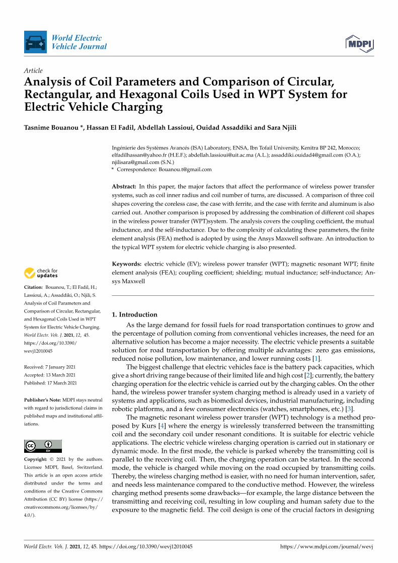
The electric vehicle presents a perfect solution for green transportation. However, themajor downside of this type of vehicle is related to the energy storage technology. Thewireless charging technology offers multiple advantages towards the battery weight, cost,and size. Figure 1 illustrates the concept of WPT charging for the electric vehicle. TheWPT system is enabled when the electric vehicle enters the charging zone. The energy istransferred then wirelessly from the power source to the battery of the vehicle using themagnetic field created between the transmitting coil and receiving coil.
Figure 1. The concept of WPT charging for the electric vehicle.
The charging system is composed of two parts: the on-board and the off-board parts.The first one is located on the vehicle, starting from the receiving coil located under thevehicle to the battery of the vehicle. The second one is located outside the vehicle, startingfrom the utility AC power source until the transmitting coil.
The SAE J2954 standard [19] proposes three possibilities for the transmitting coilposition: above the ground surface, flush with the ground surface, or buried. Moreover, thesuggested maximum permissible protrusion above the surface of the ground is 70 mm. Thisdistance can be more or less than the value stated above depending on the local installationrules. For now, the transmitting coil above the ground is the case adopted here. Addition-ally, to classify the WPT systems based on the estimated maximum ground clearance, threeZ-classes are defined: Z1 = 100–150 mm, Z2 = 140–210 mm, and Z3 = 170–250 mm.
The most prevalent WPT technologies are inductive coupling and magnetic reso-nant coupling. Inductive coupling is a technique commonly used in wireless chargingapplications. Its range of operation is limited to short distances of less than a centime-ter [20]. Moreover, its performance falls dramatically when there is a misalignment betweenthe transmitting coil and the receiving coil, even when the misalignment is only a fewcentimeters [21].
Magnetic resonant coupling is a technique that was developed by [4]. Its range ofoperation can reach longer distances, and the energy is transmitted from the transmittingcoil to the receiving one with high power transfer efficiency and with minimal energylosses. Figure 2 presents a block diagram of the unidirectional magnetic resonance wirelesspower transfer for electric vehicle charging.

World Electr. Veh. J. 2021, 12, 45 4 of 25
Figure 2. Unidirectional magnetic resonance wireless power transfer for electric vehicle charging.
Firstly, the utility AC power is converted to DC power by using a rectifier containinga power factor correction; then, a high-frequency inverter is used to power the compen-sation network and the transmitting coil. The high current flowing in the transmittingcoil generates an alternating magnetic field; this magnetic field induces a voltage in thereceiving coil.
Secondly, the voltage induced is rectified using an AC/DC converter, which is used tocharge the battery through the battery management system (BMS). The resonance betweenthe two compensation networks improves the transferred power and efficiency [22].
2.2. The Magnetic Resonant WPT System
In this section, the induction part of the charging system and the magnetic resonantsystem’s equivalent circuit are discussed.
The working theory of wireless power transfer is regulated by the laws of Ampere andFaraday. Ampere’s law states that a magnetic field is generated when an electric currentflows through a conductor in free space. (1) indicates the relation between the magneticfield BT created and the electric current flowing in the transmitting coil I1, where ∆l is theunit length of the conductor and N1 is the number of turns of the transmitting coil.
∑ BT∆l = µ0 I1N1 (1)
Faraday’s law states that when a time-varying magnetic field relates to a conductor, itwill cause a voltage to be induced in the conductor. (2) indicates the relation between thevoltage e and the rate of change in magnetic flux φB, where N2 is the number of turns ofthe receiving coil.
e = −N2dφBdt
(2)
The WPT principle is based on two coils isolated by an air gap. The transmittingcoil located in the ground is powered by the AC with high frequency. As a result, a time-varying magnetic field is created according to Ampere’s law. The generated magnetic fieldis captured by the receiving coil located below the electric vehicle and, due to Faraday’s law,the magnetic field induces a voltage. The coupling coefficient k between the transmittingcoil and the receiving coil plays a significant role in achieving high efficiency [2]. It isrelated to the mutual inductance by the following expression (3):
M = k√
L1L2 (3)
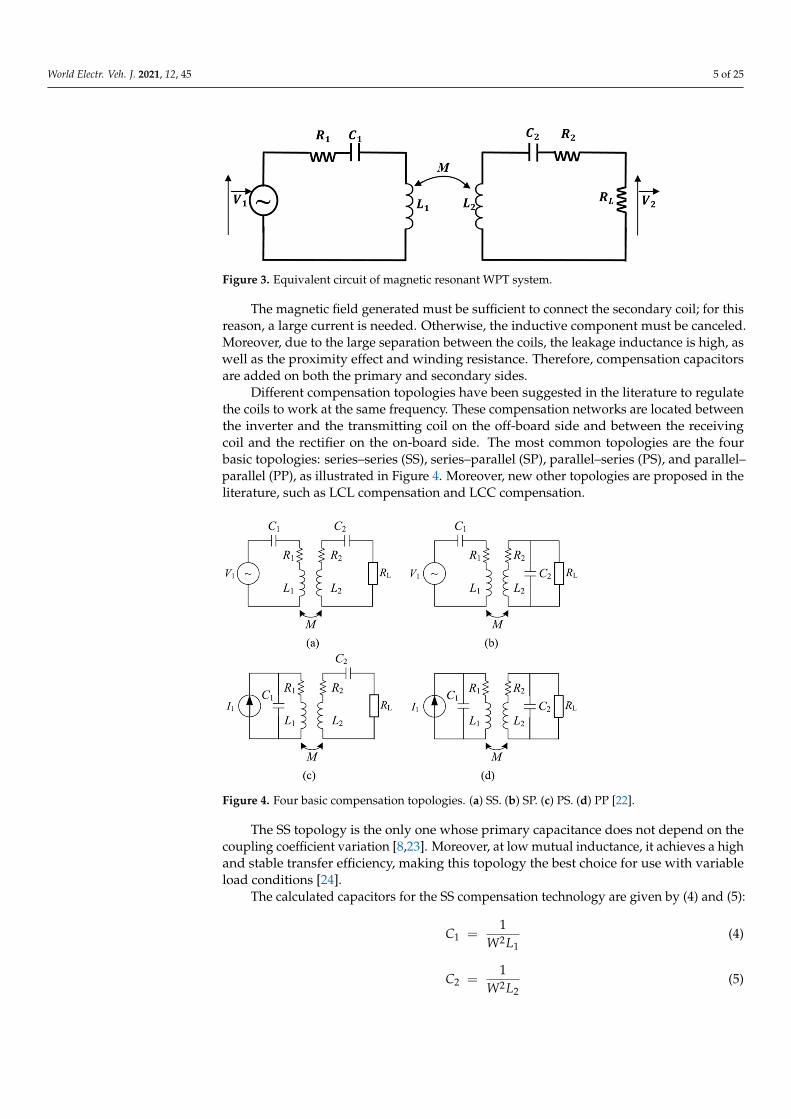
Figure 3 shows the equivalent circuit of the magnetic resonant WPT system model forthe electric vehicle, where L1, R1, and C1 are, respectively, the inductance, the resistance,and the capacitor of the primary side; L2, R2, and C2 are, respectively, the inductance, theresistance, and the capacitor of the secondary side; RL is the equivalent load resistance andM is the mutual inductance between coils.
World Electr. Veh. J. 2021, 12, 45 5 of 25
Figure 3. Equivalent circuit of magnetic resonant WPT system.
The magnetic field generated must be sufficient to connect the secondary coil; for thisreason, a large current is needed. Otherwise, the inductive component must be canceled.Moreover, due to the large separation between the coils, the leakage inductance is high, aswell as the proximity effect and winding resistance. Therefore, compensation capacitorsare added on both the primary and secondary sides.
Different compensation topologies have been suggested in the literature to regulatethe coils to work at the same frequency. These compensation networks are located betweenthe inverter and the transmitting coil on the off-board side and between the receivingcoil and the rectifier on the on-board side. The most common topologies are the fourbasic topologies: series–series (SS), series–parallel (SP), parallel–series (PS), and parallel–parallel (PP), as illustrated in Figure 4. Moreover, new other topologies are proposed in theliterature, such as LCL compensation and LCC compensation.
Figure 4. Four basic compensation topologies. (a) SS. (b) SP. (c) PS. (d) PP [22].
The SS topology is the only one whose primary capacitance does not depend on thecoupling coefficient variation [8,23]. Moreover, at low mutual inductance, it achieves a highand stable transfer efficiency, making this topology the best choice for use with variableload conditions [24].
The calculated capacitors for the SS compensation technology are given by (4) and (5):
C1 =1
W2L1(4)
C2 =1
W2L2(5)

World Electr. Veh. J. 2021, 12, 45 6 of 25
The present analysis reveals the relationship between the efficiency η and the mu-tual inductance M. The voltage equations of the transmitter and receiver sections can beexpressed as:
V1 = ZT1 I1 − jwMI2 (6)
jwMI1 = ZT2 I2 (7)
where ZT1 and ZT2 are the transmitter and receiver coil impedances, respectively, whichcan be expressed as:
ZT1 =1
jwC1+ R1 + jwL1 (8)
ZT2 =1
jwC2+ R2 + RL + jwL2 (9)
When the system reaches the resonance frequency, and according to (4)–(6), the voltageV1 and the current circulating in the second section I2 are rewritten as:
V1 = R1 I1 − jwMI2 (10)
I2 =jwM
R2 + RL× I1 (11)
The input power delivered by the voltage source Pin and the output power of the loadPout are:
Pin = V1 II =R1 × (R2 + RL) + (wM)2
R2 + RL× I1
2 (12)
Pout = RL I22 = RL ×
w2M2 I12
(R2 + RL)2 (13)
The power transfer efficiency η is then:
η =Pout
Pin=
RL × (wM)2
(R2 + RL)× [R1 × (RL + R2) + (wM)2](14)
If we consider the following condition, RL � R2, the efficiency is rewritten as:
η ≈ 1
1 + R1RL(wM)2
(15)
Consequently, the high frequency and the large mutual inductance imply high efficiency.
3. Impacts of Coil Parameters and Coil Position on the WPT System Performance
In WPT systems for EV applications, the design of the coils used for transferring andreceiving the energy must be optimized to improve the system performance. Therefore, itis essential to study what has the most impact on the coupling and efficiency of coils.
The coupling coefficient, the mutual inductance, and the coil self-inductance are thekey factors in ensuring high coupling between coils. They are impacted by the coil-to-coilrelative position, the addition of materials, and the coil structural parameters.
The analysis of these factors by calculation has limitations; the finite element analysis(FEA) method is the best way to execute these calculations.
The finite element method (FEM) is a numerical method based on determining ap-proximate solutions. The main aspect of this method is to subdivide a complex probleminto small pieces to generate a system of simple equations. The solutions of these equationsare combined to reach the final solution.
Ansys Maxwell is a powerful finite element analysis (FEA) software program thatoffers many solvers to evaluate the electromagnetic component design. The system issubdivided into elements according to the mesh (a three-dimensional grid that defines
World Electr. Veh. J. 2021, 12, 45 7 of 25
the elements). The mesh can define elements of uniform size and shape or elements ofdifferent shapes and sizes in different parts of the domain.
The boundary conditions in the Ansys Maxwell software determine the magneticfield behavior at the interfaces or the edges of the problem region. For the wireless powertransfer system, the boundary conditions in the eddy current solver are determined bythe air region and/or box whereby the four terminals of two coils touch the face of theboundary. Accordingly, the default parameters can be explained as follows (Table 1):
• Polygon segment: number of cross-section polygon segments;• Polygon radius: outer radius of cross-section polygon;• Start helix radius: start radius from polygon center to helix center, which means the
radius of the first turn of the coil;• Radius change: the distance between consecutive turns of the coil;• Pitch: the height of the coil in the z-direction;• Turns: the number of turns of the coil;• Segment per turn: number of segments per turn.
Table 1. Default parameters for the model.
CoilMaterial
PolygonSegment
PolygonRadius
Start HelixRadius
RadiusChange
Winding Numberof Turns
Segment perTurn Pitch
copper 4 1 mm 20 mm 2.05 mm 10 36 0
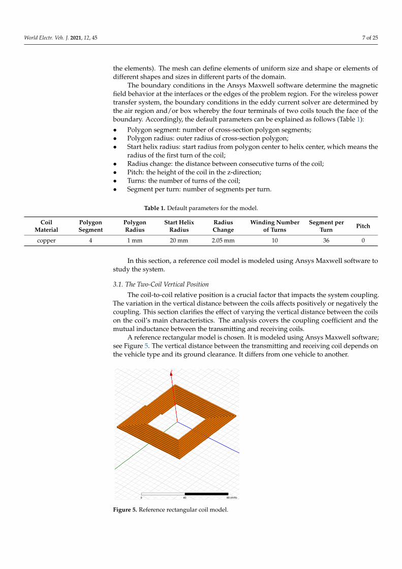
In this section, a reference coil model is modeled using Ansys Maxwell software tostudy the system.
3.1. The Two-Coil Vertical Position
The coil-to-coil relative position is a crucial factor that impacts the system coupling.The variation in the vertical distance between the coils affects positively or negatively thecoupling. This section clarifies the effect of varying the vertical distance between the coilson the coil’s main characteristics. The analysis covers the coupling coefficient and themutual inductance between the transmitting and receiving coils.
A reference rectangular model is chosen. It is modeled using Ansys Maxwell software;see Figure 5. The vertical distance between the transmitting and receiving coil depends onthe vehicle type and its ground clearance. It differs from one vehicle to another.
Figure 5. Reference rectangular coil model.
World Electr. Veh. J. 2021, 12, 45 8 of 25
The gap is the vertical distance between the upper extremity of the transmitting coiland the lower extremity of the receiving coil.
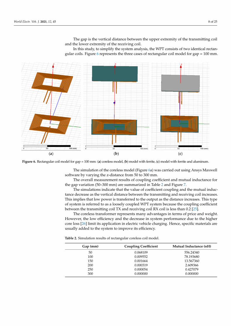
In this study, to simplify the system analysis, the WPT consists of two identical rectan-gular coils. Figure 6 represents the three cases of rectangular coil model for gap = 100 mm.
Figure 6. Rectangular coil model for gap = 100 mm: (a) coreless model, (b) model with ferrite, (c) model with ferrite and aluminum.
The simulation of the coreless model (Figure 6a) was carried out using Ansys Maxwellsoftware by varying the z-distance from 50 to 300 mm.
The overall measurement results of coupling coefficient and mutual inductance forthe gap variation (50–300 mm) are summarized in Table 2 and Figure 7.
The simulations indicate that the value of coefficient coupling and the mutual induc-tance decrease as the vertical distance between the transmitting and receiving coil increases.This implies that low power is transferred to the output as the distance increases. This typeof system is referred to as a loosely coupled WPT system because the coupling coefficientbetween the transmitting coil TX and receiving coil RX coil is less than 0.2 [25].
The coreless transformer represents many advantages in terms of price and weight.However, the low efficiency and the decrease in system performance due to the highercore loss [26] limit its application in electric vehicle charging. Hence, specific materials areusually added to the system to improve its efficiency.
Table 2. Simulation results of rectangular coreless coil model.
Gap (mm) Coupling Coefficient Mutual Inductance (nH)
50 0.068109 556.24340100 0.009552 78.193680150 0.001664 13.567360200 0.000319 2.609366250 0.000054 0.427079300 0.000000 0.000000

World Electr. Veh. J. 2021, 12, 45 9 of 25
Figure 7. Rectangular coreless model: (a) coupling coefficient versus the gap variation, (b) mutualinductance versus the gap variation.
3.2. The Introduction of Ferrite and Aluminum to the Coil System
Several studies have been carried out to enhance the weak coupling resulting fromthe two coils inductively coupled; one of the efficient methods is the integration of newmaterials into the system. These materials should not affect the electrical performance ofthe system. The main objective is to enhance the coupling between the coils and minimizethe leakage flux by guiding the flux from the transmitter coil to the receiver coil.
The relative permeability of ferrite is high and can reduce the reluctance path [26].Moreover, according to [27], the hysteresis loop of Mn-Zn ferrite is narrow, which helps tominimize hysteresis loss. As a result, ferrite bars or plates are often used to guide magneticflux and provide magnetic shielding.
A simple analysis is performed using a ferrite plate to analyze the coupling concern-ing the gap variation. The same rectangular shape is chosen. Figure 6b illustrates therectangular coil with ferrite for gap = 100 cm.
Table 3 and Figure 8 depict the simulation results of the coupling coefficient andmutual inductance for the gap variation (50 to 300 mm).
The result shows that the coupling coefficient and the mutual inductance valuesdecrease as the z-distance increases. Moreover, the values have been greatly increasedcompared to the coreless results. The ferrite is dedicated to providing an alternative pathfor the lines of the magnetic flux and changing its usual path [28].

World Electr. Veh. J. 2021, 12, 45 10 of 25
Table 3. Simulation results of rectangular coil model with ferrite.
Gap (mm) Coupling Coefficient Mutual Inductance (µH)
50 0.101212 1.452432100 0.013244 0.189907150 0.002227 0.031972200 0.000425 0.006089250 0.000081 0.001156300 0.000012 0.000169
Figure 8. Rectangular coil model with ferrite: (a) coupling coefficient versus the gap variation, (b)mutual inductance versus the gap variation.
Otherwise, among the advantages of using ferrite, it can reduce the serious risks forthe user’s health. Thereby, it is considered magnetic shielding. However, this type ofshielding may not be sufficient to protect users and respect the guidance of the ICNIRPstandard [29].
An aluminum plate is added to the system to analyze its influence on the coupling.Figure 6c shows the rectangular coil with ferrite and aluminum for gap = 100 mm.
The simulation results of the coupling coefficient and the mutual inductance aresummarized in Table 4 and Figure 9.

World Electr. Veh. J. 2021, 12, 45 11 of 25
Table 4. Simulation results of rectangular coil model with ferrite and aluminum.
Gap (mm) Coupling Coefficient Mutual Inductance (µH)
50 0.100854 1.448542100 0.013164 0.188223150 0.002217 0.031680200 0.000423 0.006059250 0.000081 0.001157300 0.000013 0.000179
Figure 9. Rectangular coil model with ferrite and aluminum: (a) coupling coefficient versus the gapvariation, (b) mutual inductance versus the gap variation.
It can be concluded that the coil with ferrite represents the highest coupling coefficientvalue among all three cases (case 1: coreless coil, case 2: a coil with ferrite, case 3: a coilwith ferrite and aluminum). This result is due to the ferrite, which collects the flux andguides it along another path.
The introduction of aluminum to the rectangular coil with ferrite reduces marginallythe coupling coefficient value while remaining relatively high [2]. According to [3,30], it ispossible to reduce the variation in circuit parameters while maintaining the shielding effectif the ferrite is positioned between the coil and aluminum plate and the thickness of thealuminum is greater than the skin depth.
There are several types of shielding in the literature [3,31,32]. The working principleof conductive shielding can be explained as follows: the magnetic field generated by thecoils induces eddy currents in the aluminum shield. These eddy currents in turn create anopposing magnetic field to attenuate or even cancel out the incident magnetic field [16,31].

World Electr. Veh. J. 2021, 12, 45 12 of 25
Hence, by adding the ferrite and aluminum to the system, the characteristics are alsomerged. This means that the coupling is increased compared to case 1 and the magneticfield is better shielded compared to case 2.
The limitation and guidance of magnetic flux lines not only lead to a decrease in theleakage magnetic field but also an increase in coupling coefficient and mutual inductance.
In summary, both ferrite and aluminum are necessary to ensure good coupling andbetter shielding to meet the ICNIRP guidelines (ICNIRP).
3.3. Coil Main Parameters
The coupling coefficient, self-inductance, and the mutual inductance of two coils areconsidered as crucial factors determined by coil parameters that affect the system perfor-mance. Therefore, improvement of the coil parameters is a suitable means of enhancing thesystem coupling. The variation in coil parameters affects the system coupling by varyingeither the number of turns or the inner radius or other parameters. In this section, theimpact of varying these parameters on the system coupling is analyzed. The simulationswere performed by modeling a circular coil using Ansys Maxwell software (Figure 10).Accordingly, the model characteristics can be explained as follows (Table 5):
Figure 10. Reference circular coil model.
Table 5. Circular coil model characteristics.
Coil Material Winding Number of Turns Winding Diameter Pitch
Copper 10 Outer 80 mmInner 40 mm 0
3.3.1. The Coil Inner Radius
In this analysis, the inner radius of the transmitting coil is kept constant, RTX = 20 mm,and that of the receiving coil RRX is changed from 10 to 40 mm. Figure 11 illustratesan example of two cases: (a) RRX = 10 mm and (b) RRX = 40 mm. The number ofturns for both coils is equal to NRX = NTX = 20 mm. The simulation results of thecoupling coefficient regarding the receiving coil inner radius variation for gap = 100 mmare illustrated in Table 6 and Figures 12 and 13.
The inner radius of the receiving coil in the first image is equal to 10 mm and the innerradius of the receiving coil in the second image is equal to 40 mm.
The same procedure is applied to the transmitting coil. The inner radius of thereceiving coil is constant and we change that of the transmitting coil. The other parametersare kept the same.
Figure 14 illustrates an example of two cases: (a) RTX = 10 mm and (b) RTX = 40 mm.

World Electr. Veh. J. 2021, 12, 45 13 of 25
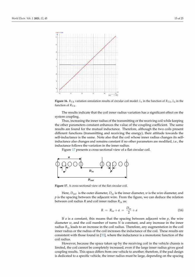
The simulation result of the coupling coefficient regarding the transmitting coil innerradius variation for gap = 100 mm is shown in Table 7 and Figures 15 and 16.
Table 6. Simulation results of circular coil model—RRX variation.
RRX 10 15 20 25 30 35 40
Coupling coefficient 0.005816 0.007161 0.008412 0.009585 0.010463 0.011186 0.011684Mutual inductance (nH) 30.424290 44.193950 59.199180 74.752330 89.813510 103.64980 115.51350
L1 (µH) 6.780342 6.779160 6.785520 6.791254 6.794025 6.793827 6.798295L2 (µH) 4.036471 5.617566 7.298441 9.050857 10.844590 12.637880 14.37701
Table 7. Simulation results of circular coil model—RTX variation.
RTX 10 15 20 25 30 35 40
Coupling coefficient 0.005711 0.007095 0.008412 0.009605 0.010627 0.011418 0.011990Mutual inductance (nH) 30.39108 44.18762 59.19918 74.67751 89.77743 103.5061 115.4117
L1 (µH) 3.874879 5.307868 6.785520 8.276253 9.770129 11.25197 12.68043L2 (µH) 7.308522 7.308452 7.298441 7.303525 7.305497 7.302940 7.307154
Figure 11. Coreless coil models with constant RTX : (a) RRX = 10 mm, (b) RRX = 40 mm for gap = 100 mm.
Figure 12. RRX variation simulation results of circular coil model: k in the function of RRX and M in the function of RRX .

World Electr. Veh. J. 2021, 12, 45 14 of 25
Figure 13. RRX variation simulation results of circular coil model: L1 in the function of RRX , L2 inthe function of RRX .
Figure 14. Coreless coil models with constant RTX : (a) RRX = 10 mm, (b) RRX = 40 mm for gap = 100 mm.
Figure 15. RTX variation simulation results of circular coil model: k in the function of RTX , M in the function of RTX .
World Electr. Veh. J. 2021, 12, 45 15 of 25
Figure 16. RTX variation simulation results of circular coil model: L1 in the function of RTX , L2 in thefunction of RTX .
The results indicate that the coil inner radius variation has a significant effect on thesystem coupling.
Thus, increasing the inner radius of the transmitting or the receiving coil while keepingthe other parameters constant enhances the value of the coupling coefficient. The sameresults are found for the mutual inductance. Therefore, although the two coils presentdifferent functions (transmitting and receiving the energy), their attitude towards theself-inductance is the same. Note also that the coil whose inner radius changes its self-inductance also changes and remains constant if no other parameters are modified, i.e., theinductance follows the variation in the inner radius.
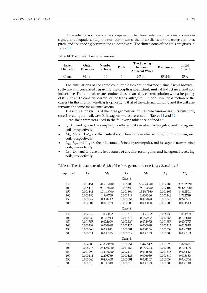
Figure 17 presents a cross-sectional view of a flat circular coil.
Figure 17. A cross-sectional view of the flat circular coil.
Here, Dout is the outer diameter, Din is the inner diameter, w is the wire diameter, andp is the spacing between the adjacent wire. From the figure, we can deduce the relationbetween coil radius R and coil inner radius Rin as:
R = Rin + a =Din2
+ a (16)
If a is a constant, this means that the spacing between adjacent wire p, the wirediameter w, and the coil number of turns N is constant, and any increase in the innerradius Rin leads to an increase in the coil radius. Therefore, any augmentation in the coilinner radius or the radius of the coil increases the inductance of the coil. These results areconsistent with those found in [33], where the inductance is a monotonic function of thecoil radius.
However, because the space taken up by the receiving coil in the vehicle chassis islimited, the coil cannot be completely increased, even if the large inner radius gives goodcoupling results. This space differs from one vehicle to another; therefore, if the pad designis dedicated to a specific vehicle, the inner radius must be large, depending on the spacing

World Electr. Veh. J. 2021, 12, 45 16 of 25
offered. On the other hand, if the pad is designed to be suitable for different types ofvehicles, its parameters, including the inner radius, must follow dedicated standards.
3.3.2. The Coil Number of Turns
In this analysis, the number of turns of the transmitting coil is preserved constantlyNTX = 10 and we change that of the receiving coil from 5 to 16. The inner radius for bothcoils is equal to RRX = RTX = 20 mm. The simulation results of the coupling coefficientregarding the receiving coil number of turns for gap = 100 mm are illustrated in Table 8and Figures 18 and 19.
Table 8. Simulation results of circular coil model—number of turns NRX variation.
Number of Turns NRX 5 7 10 13 16
Coupling coefficient 0.005873 0.006941 0.008412 0.009744 0.010916Mutual inductance (nH) 21.589390 34.704880 59.199180 89.343810 123.96730
L1 (µH) 6.784625 6.792092 6.785520 6.787126 6.774364L2 (µH) 1.991499 3.680638 7.298441 12.386530 19.039200
Figure 18. Number of turns simulation results of circular coil model: k in the function of NRX , M in the function of NRX .
Figure 19. Number of turns simulation results of circular coil model: L1 in the function of NRX , L2 inthe function of NRX .

World Electr. Veh. J. 2021, 12, 45 17 of 25
The same procedure is applied to the transmitting coil. The inner radius of thereceiving coil is constant and that of the transmitting coil is changed. The other parametersare kept the same.
The simulation result of the coupling coefficient regarding the transmitting coil num-ber of turns variation for gap = 100 mm is shown in Table 9 and Figures 20 and 21.
Table 9. Simulation results of circular coil model—number of turns NTX variation.
Number of Turns NTX 5 7 10 13 16
Coupling coefficient 0.006331 0.006856 0.008412 0.009836 0.011129Mutual inductance (nH) 27.788710 34.660960 59.199180 89.228940 123.91930
L1 (µH) 2.639758 3.498766 6.785520 11.276280 16.990020L2 (µH) 7.299475 7.304379 7.298441 7.298372 7.296844
Figure 20. Number of turns simulation results of circular coil model: k in the function of NTX , M in the function of NTX .
Figure 21. Number of turns simulation results of circular coil model: L1 in the function of NTX , L2 inthe function of NTX .
The results indicate that the coil number of turns affects the system coupling. Increas-ing the number of turns of the transmitting and receiving coils while keeping the other

World Electr. Veh. J. 2021, 12, 45 18 of 25
parameters constant enhances the coupling coefficient and the mutual inductance values.Furthermore, for the coil whose number of turns increases, its inductance also increases andremains constant if no parameters are modified, i.e., the inductance follows the variation inthe number of turns.
Moreover, if the number of turns increases, the outer diameter increases effectivelyby default. Here, the concept of misalignment is introduced. The misalignment is a majorfactor that we should take into consideration while designing the coils. According to SAEJ2954 (SAE), the lateral misalignment tolerance among the x-axis (vehicle movement) is±100 mm, so if we consider that the outer diameter of the transmitting coil is namedDTXout, the diameter of the receiving coil must then be DRXout:
DRXout = DTXout − 200 mm (17)
This expression ensures that the misalignment is reduced according to the misalign-ment tolerance.
Therefore, increasing the number of turns of the coil remains an effective method toimprove the inductance of the coil and to improve the coupling coefficient in the wirelesspower transfer system, taking into account the notion of misalignment.
It can be concluded that the coupling coefficient, mutual inductance, and coil induc-tance depend on the coil parameters and the relative position of the coils. Effectively, thestudy results reveal that the optimized design of the coil inner radius and number of turnsis beneficial in improving the coupling and mutual inductance abilities.
4. Comparison of Three Coil Shapes for EV Charging Application4.1. The Three Coil Shapes’ Comparison
In this section, three coil shapes are presented: circular, rectangular, and hexagonal(Figure 22). The main objective is to compare the coupling coefficient, the mutual induc-tance, and the coil inductance for the three coil shapes. The comparison is set for airgaps of z = 50 mm up to z = 300 mm with steps of 50 mm and for zero misalignments(dx = dy = 0).
Figure 22. The three cases: (a) circular coreless model, (b) rectangular coreless model, (c) hexagonal coreless model.
World Electr. Veh. J. 2021, 12, 45 19 of 25
For a reliable and reasonable comparison, the three coils’ main parameters are de-signed to be equal, namely the number of turns, the inner diameter, the outer diameter,pitch, and the spacing between the adjacent wire. The dimensions of the coils are given inTable 10.
Table 10. The three coil main parameters.
InnerDiameter
OuterDiameter
Numberof Turns Pitch
The Spacingbetween
Adjacent WiresFrequency Initial
Current
40 mm 80 mm 10 0 0.7 mm 85 kHz 25 A
The simulations of the three coils topologies are performed using Ansys Maxwellsoftware and compared regarding the coupling coefficient, mutual inductance, and coilinductance. The simulations are conducted using an eddy current solution with a frequencyof 85 kHz and a constant current of the transmitting coil. In addition, the direction of thecurrent in the internal winding is opposite to that of the external winding and the coil sizeremains the same for all simulations.
The simulation results of the three geometries for the three cases—case 1: circular coil,case 2: rectangular coil, case 3: hexagonal—are presented in Tables 11 and 12.
Here, the parameters used in the following tables are defined as:
• kc, kr, and kh are the coupling coefficient of circular, rectangular, and hexagonalcoils, respectively;
• Mc, Mr, and Mh are the mutual inductance of circular, rectangular, and hexagonalcoils, respectively;
• L1c, L1r, and L1h are the inductance of circular, rectangular, and hexagonal transmittingcoils, respectively;
• L2c, L2r, and L2h are the inductance of circular, rectangular, and hexagonal receivingcoils, respectively.
Table 11. The simulation results (k, M) of the three geometries: case 1, case 2, and case 3.
Gap (mm) kc Mc kr Mr kh Mh
Case 1
50 0.063451 445.95400 0.068109 556.24340 0.057182 397.82520100 0.008412 59.199180 0.009552 78.193680 0.007409 51.661350150 0.001441 10.143700 0.001664 13.567360 0.001265 8.812501200 0.000280 1.969708 0.000319 2.609366 0.000246 1.712719250 0.000049 0.331442 0.000054 0.427079 0.000043 0.290551300 0.000004 0.017259 0.000000 0.000000 0.000003 0.001513
Case 2
50 0.087542 1.052032 0.101212 1.452432 0.086132 1.084909100 0.010632 0.127913 0.013244 0.189907 0.010165 0.127640150 0.001755 0.021099 0.002227 0.031972 0.001658 0.020777200 0.000339 0.004080 0.000425 0.006089 0.000312 0.003920250 0.000068 0.000811 0.000081 0.001156 0.000059 0.000740300 0.000011 0.000125 0.000012 0.000169 0.000009 0.000103
Case 3
50 0.064083 690.79670 0.100854 1.448542 0.085573 1.072621100 0.006945 75.680240 0.013164 0.188223 0.010104 0.126605150 0.001097 11.840260 0.002217 0.031680 0.001645 0.020617200 0.000211 2.298739 0.000423 0.006059 0.000310 0.003883250 0.000045 0.480430 0.000081 0.001157 0.000059 0.000734300 0.000010 0.105318 0.000013 0.000179 0.000009 0.000110
World Electr. Veh. J. 2021, 12, 45 20 of 25
Table 12. The simulation results (L1, L2) of the three geometries: case 1, case 2, and case 3.
Gap (mm) L1c L2c L1r L2r L1h L2h
Case 1
50 0.064083 690.79670 0.100854 1.448542 0.085573 1.072621100 0.006945 75.680240 0.013164 0.188223 0.010104 0.126605150 0.001097 11.840260 0.002217 0.031680 0.001645 0.020617200 0.000211 2.298739 0.000423 0.006059 0.000310 0.003883250 0.000045 0.480430 0.000081 0.001157 0.000059 0.000734300 0.000010 0.105318 0.000013 0.000179 0.000009 0.000110
Case 2
50 11.947130 12.088330 14.298380 14.402650 12.562350 12.629550100 11.950400 12.110930 14.266830 14.412460 12.513560 12.600940150 11.957580 12.091200 14.256900 14.457540 12.474230 12.589890200 11.926060 12.117880 14.263890 14.402940 12.515170 12.633200250 11.941690 11.923480 14.226600 14.216720 12.504320 12.497870300 11.808270 10.570560 14.300310 12.999270 12.510930 11.797060
Case 3
50 10.781420 10.777930 14.281620 14.444460 12.492290 12.577110100 10.869160 10.925570 14.209700 14.387980 12.471550 12.590100150 10.792140 10.799971 14.204850 14.378430 12.469870 12.593910200 10.903430 10.917850 14.243580 14.429750 12.455440 12.570840250 10.785930 10.783920 14.226220 14.227060 12.458240 12.445430300 10.864260 10.687310 14.189000 13.187760 12.458490 11.860980
For the coreless case, the results show that the rectangular shape represents thegreatest coupling coefficient k and mutual inductance M compared to the circular andhexagonal shapes.
The circular coil is the second shape that has a good coupling coefficient, while thecoupling coefficient of the hexagonal coil is also close to this value.
The introduction of ferrite and aluminum into the coils enhances the coupling coeffi-cient values for all shapes, as can be concluded from Section 3. Notably, the rectangularshape still presents the best values.
Moreover, the transmitting coil inductance remains unchanged when the verticaldistance is varied. Effectively, there is no change in the coil parameters and the currentflowing in the transmitting coil is considered constant. When the ferrite is added, the induc-tance improves and remains constant over all gap variation. Moreover, the introduction ofaluminum into the system composed of coil and ferrite marginally reduces the inductancevalue, which remains notably high. In this case, the rectangular coil presents the best valueof L2 compared to the circular and hexagonal, especially after adding the ferrite.
On the other hand, the rectangular and hexagonal receiving coils’ inductance in thecoreless case decrease with the large vertical distances (300 mm). This influence diminishesby adding ferrite and aluminum. However, the receiving circular coil inductance remains ahigh value basically in the large vertical distances.
These results give the advantage to the rectangular shape, with high coupling andinductance values, over other shapes for the variation in the gap under the given conditions.Other factors that can alter these results are the static or dynamic type of charging of electricvehicles and the misalignment of coils along the x and y-axis. Therefore, these coils are ofdifferent natures and are suitable for specific applications.
Several studies have been carried out to determine the coil inductance expressions,namely the modified Wheeler formula, the expression based on current sheet approxima-tion, and the data-fitted monomial expression [34]. Thereby, the ratio between the currentflowing through the coil and the magnetic flux generated represents its self-inductance [35].

World Electr. Veh. J. 2021, 12, 45 21 of 25
Hence, the self-inductance of the coil is expressed as follows [34]:
L =µN2davgC1
2
(ln(
C2
ρ
)+ C3ρ + C4ρ2
)(18)
where µ0 is the permeability of free space, N is the number of turns, dout and din are theouter and inner diameters of the coil, davg = din+dout
2 is the average diameter, ρ = dout−dindout+din
is the fill factor. The coefficients Ci are layout-dependent, as illustrated in Table 13.
Table 13. Coefficients for current sheet expression.
Layout C1 C2 C3 C4
Square 1.27 2.07 0.18 0.13Hexagonal 1.09 2.23 0.00 0.17Octagonal 1.07 2.29 0.00 0.19
Circle 1.00 2.46 0.00 0.20
4.2. The Nine Possibilities of the Three Shapes’ Combination
There are different possible shapes for the receiving coil attached to the bottom ofvehicles, the same as for the transmitting coils located at charging stations. For this,we propose in this part nine possibilities that can be encountered in wireless chargingoperations using the three coil shapes: circular, rectangular, and hexagonal. Each shape ofthe transmitting coil corresponds to the three shapes of the receiving coil. The topologiesconsist of air-core coils without any material to ensure equitable comparison.
To compare the nine possibilities of shaped coils, their self- and mutual inductancesand coupling coefficients were calculated using FEM software.
The modeling of the different coils can be considered the same as in the section above.The 3-D models created in ANSYS Maxwell software for the nine shapes’ cases can bedescribed as follows:
Case 1: circular transmitter coil and circular receiving coil;Case 2: circular transmitter coil and rectangular receiving coil;Case 3: circular transmitter coil and hexagonal receiving coil;Case 4: rectangular transmitter coil and circular receiving coil;Case 5: rectangular transmitter coil and rectangular receiving coil;Case 6: rectangular transmitter coil and hexagonal receiving coil;Case 7: hexagonal transmitter coil and circular receiving coil;Case 8: hexagonal transmitter coil and rectangular receiving coil;Case 9: hexagonal transmitter coil and hexagonal receiving coil.
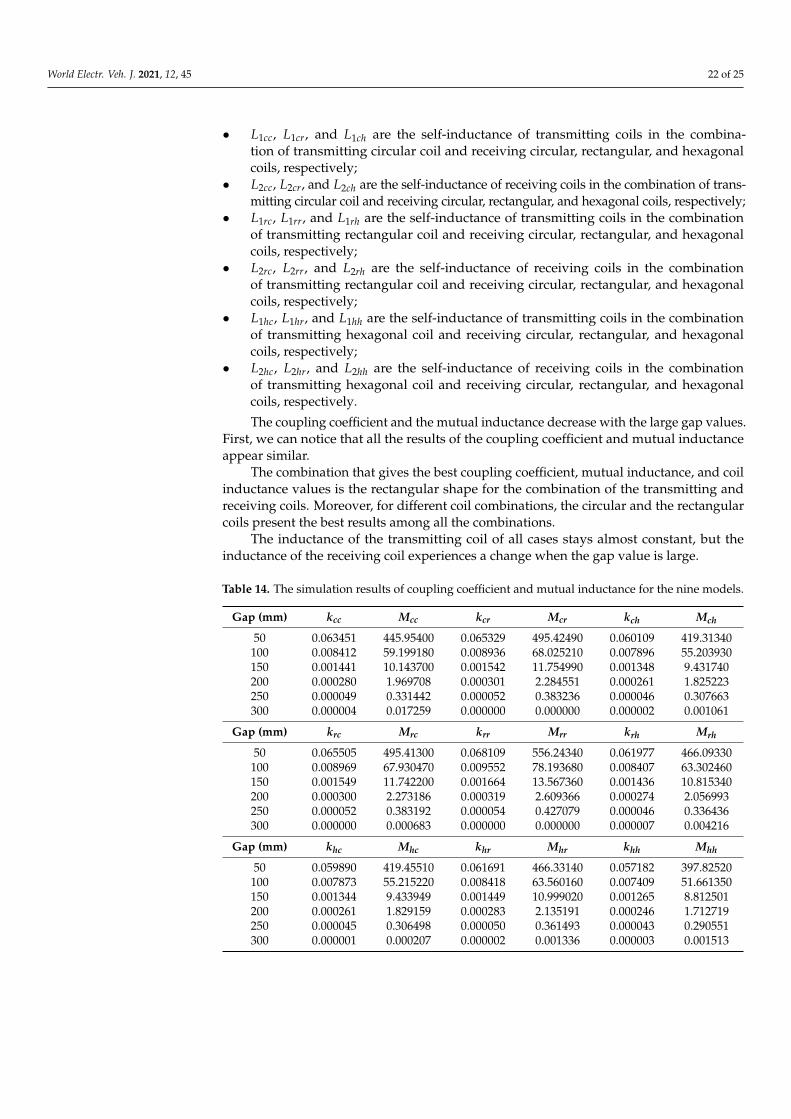
The simulation results of the coils for the nine cases are presented in Tables 14 and 15.Here, the parameters used in the following tables are defined as follows:
• kcc, kcr, and kch are the coupling coefficients of the combination of transmitting circularcoil and receiving circular, rectangular, and hexagonal coils, respectively;
• Mcc, Mcr, and Mch are the mutual inductances of the combination of transmittingcircular coil and receiving circular, rectangular, and hexagonal coils, respectively;
• krc, krr, and krh are the coupling coefficients of the combination of transmitting rectan-gular coil and receiving circular, rectangular, and hexagonal coils, respectively;
• Mrc, Mrr, and Mrh are the mutual inductances of the combination of transmittingrectangular coil and receiving circular, rectangular, and hexagonal coils, respectively;
• khc, khr, and khh are the coupling coefficients of the combination of transmittinghexagonal coil and receiving circular, rectangular, and hexagonal coils, respectively;
• Mhc, Mhr, and Mhh are the mutual inductances of the combination of transmittinghexagonal coil and receiving circular, rectangular, and hexagonal coils, respectively;
World Electr. Veh. J. 2021, 12, 45 22 of 25
• L1cc, L1cr, and L1ch are the self-inductance of transmitting coils in the combina-tion of transmitting circular coil and receiving circular, rectangular, and hexagonalcoils, respectively;
• L2cc, L2cr, and L2ch are the self-inductance of receiving coils in the combination of trans-mitting circular coil and receiving circular, rectangular, and hexagonal coils, respectively;
• L1rc, L1rr, and L1rh are the self-inductance of transmitting coils in the combinationof transmitting rectangular coil and receiving circular, rectangular, and hexagonalcoils, respectively;
• L2rc, L2rr, and L2rh are the self-inductance of receiving coils in the combinationof transmitting rectangular coil and receiving circular, rectangular, and hexagonalcoils, respectively;
• L1hc, L1hr, and L1hh are the self-inductance of transmitting coils in the combinationof transmitting hexagonal coil and receiving circular, rectangular, and hexagonalcoils, respectively;
• L2hc, L2hr, and L2hh are the self-inductance of receiving coils in the combinationof transmitting hexagonal coil and receiving circular, rectangular, and hexagonalcoils, respectively.
The coupling coefficient and the mutual inductance decrease with the large gap values.First, we can notice that all the results of the coupling coefficient and mutual inductanceappear similar.
The combination that gives the best coupling coefficient, mutual inductance, and coilinductance values is the rectangular shape for the combination of the transmitting andreceiving coils. Moreover, for different coil combinations, the circular and the rectangularcoils present the best results among all the combinations.
The inductance of the transmitting coil of all cases stays almost constant, but theinductance of the receiving coil experiences a change when the gap value is large.
Table 14. The simulation results of coupling coefficient and mutual inductance for the nine models.
Gap (mm) kcc Mcc kcr Mcr kch Mch
50 0.063451 445.95400 0.065329 495.42490 0.060109 419.31340100 0.008412 59.199180 0.008936 68.025210 0.007896 55.203930150 0.001441 10.143700 0.001542 11.754990 0.001348 9.431740200 0.000280 1.969708 0.000301 2.284551 0.000261 1.825223250 0.000049 0.331442 0.000052 0.383236 0.000046 0.307663300 0.000004 0.017259 0.000000 0.000000 0.000002 0.001061
Gap (mm) krc Mrc krr Mrr krh Mrh
50 0.065505 495.41300 0.068109 556.24340 0.061977 466.09330100 0.008969 67.930470 0.009552 78.193680 0.008407 63.302460150 0.001549 11.742200 0.001664 13.567360 0.001436 10.815340200 0.000300 2.273186 0.000319 2.609366 0.000274 2.056993250 0.000052 0.383192 0.000054 0.427079 0.000046 0.336436300 0.000000 0.000683 0.000000 0.000000 0.000007 0.004216
Gap (mm) khc Mhc khr Mhr khh Mhh
50 0.059890 419.45510 0.061691 466.33140 0.057182 397.82520100 0.007873 55.215220 0.008418 63.560160 0.007409 51.661350150 0.001344 9.433949 0.001449 10.999020 0.001265 8.812501200 0.000261 1.829159 0.000283 2.135191 0.000246 1.712719250 0.000045 0.306498 0.000050 0.361493 0.000043 0.290551300 0.000001 0.000207 0.000002 0.001336 0.000003 0.001513

World Electr. Veh. J. 2021, 12, 45 23 of 25
Table 15. The simulation results of transmitting and receiving coil inductance for the nine models.
Gap (mm) L1cc L2cc L1cr L2cr L1ch L2ch
50 6.781647 7.284003 6.784100 8.477065 6.785677 7.171434100 6.785520 7.298441 6.808041 8.512145 6.801473 7.186742150 6.785848 7.303122 6.812742 8.525414 6.804330 7.192457200 6.785000 7.293397 6.801984 8.493260 6.789216 7.182279250 6.781005 6.781653 6.794038 7.847548 6.786111 6.732637300 6.773379 2.663993 6.768822 0.000010 6.769274 0.054358
Gap (mm) L1rc L2rc L1rr L2rr L1rh L2rh
50 7.840692 7.295153 7.859934 8.485935 7.861151 7.194426100 7.844392 7.312895 7.852931 8.533822 7.871329 7.203291150 7.857680 7.312504 7.833186 8.488914 7.867516 7.205843200 7.859005 7.295325 7.866308 8.498958 7.859830 7.179874250 7.853460 6.789841 7.866581 7.867194 7.859914 6.735969300 7.833505 0.015037 7.844216 0.000008 7.843801 0.052946
Gap (mm) L1hc L2hc L1hr L2hr L1hh L2hh
50 6.720312 7.299205 6.733408 8.486042 6.739215 7.182131100 6.727379 7.311488 6.714745 8.489664 6.753153 7.200412150 6.728282 7.317937 6.751840 8.532690 6.738836 7.202593200 6.730501 7.319607 6.717073 8.472698 6.734780 7.186359250 6.718816 6.790786 6.761878 7.865598 6.749549 6.735351300 6.709978 0.015512 6.707614 0.050624 6.705435 0.052990
These results open up potential discussions about the performance of these threeshapes according to other variations. Likewise, the rectangular coil shape presents greaterhorizontal tolerance compared to the circular one and the hexagonal coil shape presentsthe maximum power transfer efficiency at the central position [36]. Therefore, pad designremains an important field to research.
5. Conclusions
This paper discusses the wireless transfer coil system and the factors that affect ot. Thefollowing points were discussed: first, the influence of adding a ferrite core and aluminumsheet to the coil system is discussed. The result shows that the ferrite and aluminum arenecessary to guide the magnetic flux, reduce the leakage flux, protect the users around thecharging operation, and meet ICNIRP limits. Second, the large air gap reduces the couplingcoefficient and mutual inductance values. The main challenge while designing the wirelesscharger for the electric vehicle is the distance limitation between the transmitting couplerand receiving coupler. This distance depends on the electric vehicle ground clearanceand the specifications given by SAE J2954 standard. Third, the coil parameters such asinner radius and number of turns have a significant effect on the system coupling, self-inductance, and mutual inductance. The largest coil inner radius and coil number of turnsgive the best values of k, L1, L2, and M. However, the space taken up by the receiving coilin the vehicle chassis is limited, and the coil cannot be totally increased even if the largeinner radius gives good results. Finally, the comparison of three shapes, including ferriteand aluminum, gives priority to the rectangular shape, with a small difference comparedto the circular and hexagonal shapes. Thus, several coil possibilities can be encounteredduring the wireless charging operation. In our case, with the use of the three coil shapes,circular, rectangular, and hexagonal, the combination of circular and rectangular coil givesthe best results.
Further research could concentrate on the three-coil structure and the effect of thevariation of its main parameters and the shape and the size of the ferrite core and aluminumsheet on the system efficiency for bidirectional WPT system application. Moreover, thehuman safety issue must be taken into consideration during the design process, especiallywhen the power transfer is increased.
World Electr. Veh. J. 2021, 12, 45 24 of 25
Author Contributions: This paper was developed by a research team from ISA Laboratory; concep-tualization, methodology, and formal analysis, T.B. and H.E.F.; software, T.B. and A.L.; investigationand resources, T.B., A.L., O.A., and S.N.; writing, T.B.; review and supervision, H.E.F. All authorshave read and agreed to the published version of the manuscript.
Funding: The authors gratefully acknowledge the support of the Moroccan Research Institute forSolar Energy and New Energies (IRESEN) under the grant “INNO-PROJECT 2018/CBSCVEV2X”.
Conflicts of Interest: The authors declare no conflict of interest.
References1. Lassioui, A.; Fadil, H.E.; Belhaj, F.Z.; Rachid, A. Battery Charger for Electric Vehicles Based ICPT and CPT-A State of the Art. In
Proceedings of the 2018 Renewable Energies, Power Systems Green Inclusive Economy (REPS-GIE), Casablanca, Morocco, 23–24April 2018; pp. 1–6.
2. Bouanou, T.; Fadil, H.E.; Lassioui, A. Analysis and Design of Circular Coil Transformer in a Wireless Power Transfer Systemfor Electric Vehicle Charging Application. In Proceedings of the 2020 International Conference on Electrical and InformationTechnologies (ICEIT), Rabat, Morocco, 4–7 March 2020; IEEE: Rabat, Morocco, 2020; pp. 1–6.
3. Kim, J.; Kim, J.; Kong, S.; Kim, H.; Suh, I.-S.; Suh, N.P.; Cho, D.-H.; Kim, J.; Ahn, S. Coil Design and Shielding Methods for aMagnetic Resonant Wireless Power Transfer System. Proc. IEEE 2013, 101, 1332–1342. [CrossRef]
4. Kurs, A.; Karalis, A.; Moffatt, R.; Joannopoulos, J.D.; Fisher, P.; Soljacic, M. Wireless Power Transfer via Strongly CoupledMagnetic Resonances. Science 2007, 317, 83–86. [CrossRef] [PubMed]
5. Budhia, M.; Covic, G.A.; Boys, J.T. Design and Optimization of Circular Magnetic Structures for Lumped Inductive PowerTransfer Systems. IEEE Trans. Power Electron. 2011, 26, 3096–3108. [CrossRef]
6. Budhia, M.; Covic, G.; Boys, J. A New IPT Magnetic Coupler for Electric Vehicle Charging Systems. In Proceedings of the IECON2010—36th Annual Conference on IEEE Industrial Electronics Society, Glendale, AZ, USA, 7–10 November 2010; pp. 2487–2492.
7. Deng, J.; Li, W.; Nguyen, T.D.; Li, S.; Mi, C.C. Compact and Efficient Bipolar Coupler for Wireless Power Chargers: Design andAnalysis. IEEE Trans. Power Electron. 2015, 30, 6130–6140. [CrossRef]
8. Patil, D.; McDonough, M.K.; Miller, J.M.; Fahimi, B.; Balsara, P.T. Wireless Power Transfer for Vehicular Applications: Overviewand Challenges. IEEE Trans. Transp. Electrification 2018, 4, 3–37. [CrossRef]
9. Bi, Z.; Kan, T.; Mi, C.C.; Zhang, Y.; Zhao, Z.; Keoleian, G.A. A Review of Wireless Power Transfer for Electric Vehicles: Prospectsto Enhance Sustainable Mobility. Appl. Energy 2016, 179, 413–425. [CrossRef]
10. Bosshard, R.; Mühlethaler, J.; Kolar, J.W.; Stevanovic, I. Optimized Magnetic Design for Inductive Power Transfer Coils. InProceedings of the 2013 Twenty-Eighth Annual IEEE Applied Power Electronics Conference and Exposition (APEC), Long Beach,CA, USA, 17–21 March 2013; pp. 1812–1819.
11. Shi, X.; Qi, C.; Qu, M.; Ye, S.; Wang, G.; Sun, L.; Yu, Z. Effects of Coil Shapes on Wireless Power Transfer via Magnetic ResonanceCoupling. J. Electromagn. Waves Appl. 2014, 28, 1316–1324. [CrossRef]
12. Chatterjee, S.; Iyer, A.; Bharatiraja, C.; Vaghasia, I.; Rajesh, V. Design Optimisation for an Efficient Wireless Power Transfer Systemfor Electric Vehicles. Energy Procedia 2017, 117, 1015–1023. [CrossRef]
13. Yang, Y.; Cui, J.; Cui, X. Design and Analysis of Magnetic Coils for Optimizing the Coupling Coefficient in an Electric VehicleWireless Power Transfer System. Energies 2020, 13, 4143. [CrossRef]
14. Chen, W.; Liu, C.; Lee, C.H.T.; Shan, Z. Cost-Effectiveness Comparison of Coupler Designs of Wireless Power Transfer for ElectricVehicle Dynamic Charging. Energies 2016, 9, 906. [CrossRef]
15. Ongayo, D.; Hanif, M. Comparison of Circular and Rectangular Coil Transformer Parameters for Wireless Power Transfer Basedon Finite Element Analysis. In Proceedings of the 2015 IEEE 13th Brazilian Power Electronics Conference and 1st Southern PowerElectronics Conference (COBEP/SPEC), Fortaleza, Brazil, 29 November–2 December 2015; pp. 1–6.
16. Knaisch, K.; Springmann, M.; Gratzfeld, P. Comparison of Coil Topologies for Inductive Power Transfer under the Influence ofFerrite and Aluminum. In Proceedings of the 2016 Eleventh International Conference on Ecological Vehicles and RenewableEnergies (EVER), Monte Carlo, Monaco, 6–8 April 2016; pp. 1–9.
17. Knaisch, K.; Gratzfeld, P. Comparison of Magnetic Couplers for Inductive Electric Vehicle Charging Using Accurate NumericalSimulation and Statistical Methods. In Proceedings of the 2015 5th International Electric Drives Production Conference (EDPC),Nuremberg, Germany, 15–16 September 2015; pp. 1–10.
18. Aydin, E.; Kosesoy, Y.; Yildiriz, E.; Aydemir, M.T. Comparison of Hexagonal and Square Coils for Use in Wireless Charging ofElectric Vehicle Battery. In Proceedings of the 2018 International Symposium on Electronics and Telecommunications (ISETC),Timisoara, Romania, 8–9 November 2018; pp. 1–4.
19. J2954 (WIP) Wireless Power Transfer for Light-Duty Plug-in/Electric Vehicles and Alignment Methodology-SAE International.Available online: https://www.sae.org/standards/content/j2954/ (accessed on 7 September 2020).
20. Kim, J.; Choi, W.-S.; Jeong, J. Loop Switching Technique for Wireless Power Transfer using Magnetic Resonance Coupling. Prog.Electromagn. Res. 2013, 138, 197–209. [CrossRef]
21. Beh, T.C.; Kato, M.; Imura, T.; Oh, S.; Hori, Y. Automated Impedance Matching System for Robust Wireless Power Transfer viaMagnetic Resonance Coupling. IEEE Trans. Ind. Electron. 2013, 60, 3689–3698. [CrossRef]
World Electr. Veh. J. 2021, 12, 45 25 of 25
22. Siqi, L.; Mi, C.C. Wireless Power Transfer for Electric Vehicle Applications. IEEE J. Emerg. Sel. Top. Power Electron. 2015, 3, 4–17.[CrossRef]
23. Lassioui, A.; Fadil, H.E.; Rachid, A.; Belhaj, F.Z.; Tarkany, O.; Bajit, A. Characterestics Analysis of Wireless Power Transfer Systemfor Electric Vehicle Charging Applications. In Proceedings of the 2018 International Symposium on Advanced Electrical andCommunication Technologies (ISAECT), Rabat, Morocco, 21–23 November 2018; pp. 1–6.
24. Machura, P.; Li, Q. A Critical Review on Wireless Charging for Electric Vehicles. Renew. Sustain. Energy Rev. 2019, 104, 209–234.[CrossRef]
25. Lee, S.; Lee, B.; Lee, J. A New Design Methodology for a 300-KW, Low Flux Density, Large Air Gap, Online Wireless PowerTransfer System. IEEE Trans. Ind. Appl. 2016, 52, 4234–4242. [CrossRef]
26. Elnail, K.; Huang, X.; Xiao, C.; Tan, L.; Haozhe, X. Core Structure and Electromagnetic Field Evaluation in WPT Systems forCharging Electric Vehicles. Energies 2018, 11, 1734. [CrossRef]
27. Ding, W.; Wang, X. Magnetically Coupled Resonant Using Mn-Zn Ferrite for Wireless Power Transfer. In Proceedings of the 201415th International Conference on Electronic Packaging Technology, Chengdu, China, 12–15 August 2014; pp. 1561–1564.
28. Bima, M.E.; Bhattacharya, I.; Hasan, S.R. Comparative Analysis of Magnetic Materials, Coil Structures and Shielding Materials forEfficient Wireless Power Transfer. In Proceedings of the 2019 IEEE International Symposium on Electromagnetic Compatibility,Signal Power Integrity (EMC+SIPI), New Orleans, LA, USA, 22–26 July 2019; pp. 95–100.
29. ICNIRP|LF (1 Hz–100 KHz). Available online: https://www.icnirp.org/en/frequencies/low-frequency/index.html (accessedon 6 September 2020).
30. Geselowtiz, D.B.; Hoang, Q.T.N.; Gaumond, R.P. The Effects of Metals on a Transcutaneous Energy Transmission System. IEEETrans. Biomed. Eng. 1992, 39, 928–934. [CrossRef]
31. Kim, S.; Park, H.-H.; Kim, J.; Kim, J.; Ahn, S. Design and Analysis of a Resonant Reactive Shield for a Wireless Power ElectricVehicle. IEEE Trans. Microw. Theory Tech. 2014, 62, 1057–1066. [CrossRef]
32. Dolara, A.; Leva, S.; Longo, M.; Castelli-Dezza, F.; Mauri, M. Coil Design and Magnetic Shielding of a Resonant Wireless PowerTransfer System for Electric Vehicle Battery Charging. In Proceedings of the 2017 IEEE 6th International Conference on RenewableEnergy Research and Applications (ICRERA), San Diego, CA, USA, 5–8 November 2017; IEEE: San Diego, CA, USA, 2017;pp. 200–205.
33. Xu, D.; Zhang, Q.; Li, X. Implantable Magnetic Resonance Wireless Power Transfer System Based on 3D Flexible Coils.Sustainability 2020, 12, 4149. [CrossRef]
34. Mohan, S.S.; del Mar Hershenson, M.; Boyd, S.P.; Lee, T.H. Simple Accurate Expressions for Planar Spiral Inductances. IEEE J.Solid-State Circuits 1999, 34, 1419–1424. [CrossRef]
35. Jow, U.-M.; Ghovanloo, M. Design and Optimization of Printed Spiral Coils for Efficient Transcutaneous Inductive PowerTransmission. IEEE Trans. Biomed. Circuits Syst. 2007, 1, 193–202. [CrossRef] [PubMed]
36. Panchal, C.; Stegen, S.; Lu, J. Review of Static and Dynamic Wireless Electric Vehicle Charging System. Eng. Sci. Technol. Int. J.2018, 21, 922–937. [CrossRef]