Effect of co-firing on the properties of submicron aerosols from biomass combustion
Upload
independentCategory
view
0download
0
at SciVerse ScienceDirect
Applied Thermal Engineering 50 (2013) 1418e1426
Contents lists available
Applied Thermal Engineering
journal homepage: www.elsevier .com/locate/apthermeng
Analysis and optimization of a cogeneration system basedon biomass combustion
Rafal Strzalka*, Tobias Gabriel Erhart, Ursula EickerUniversity of Applied Sciences Stuttgart, Department of Building Physics, Schellingstrasse 24, 70174 Stuttgart, Germany
a r t i c l e i n f o
Article history:Received 31 May 2011Accepted 20 December 2011Available online 28 December 2011
Keywords:Mathematical modelBiomass combustionGrate furnaceRenewable cogeneration
* Corresponding author. Tel.: þ49 711 8926 2889; fE-mail address: [email protected] (R.
1359-4311/$ e see front matter � 2012 Elsevier Ltd.doi:10.1016/j.applthermaleng.2011.12.039
a b s t r a c t
The paper deals with analysis and optimization of the performance of the combustion process in a biomassfurnace at a biomass cogeneration plant. For the purpose a thermodynamicmodel for the biomass burningprocess in a grate furnace was developed. The mathematical model describes both, the thermal decom-position of the fuel on the grate as well as gas phase combustion in the secondary zone. The presentedapproach is based on energy equations for each individual step of the biomass combustion process.
Measurement results from a biomass-fired cogeneration plant were used to validate the model.Comparison between simulation and measurement results shows good agreement. The model predictsaccurately the temperature profiles in the combustion chamber.
The presented approach is suitable for model based analysis and optimization of control strategies. Thedeveloped model was used to optimize the performance of the recirculation system of the combustionappliance. The simulation based analysis showed, that the flow rate of the recirculated exhaust fumes canbe significantly reduced which results in energy savings of 17% of the auxiliary electrical power demand.
� 2012 Elsevier Ltd. All rights reserved.
1. Introduction
Biomass already plays a major role in the renewable energybalance and over 90% of energy generated from biomass isproduced in biomass furnaces [1,2]. Among the technologies forenergy production from solid biomass, combustion is the mostadvanced and market-proven application, while pyrolysis andgasification are still in the development stage [3,4]. Consequentlycombustion of biomass has been found to be the most promisingmethod for biomass utilization. However, biomass has a relativelylow bulk density and therefore it can be characterized by significantcosts for storage and transportation. For that reason utilization ofbiomass as a fuel is reasonable rather in decentralized energyproduction facilities [5]. Another important issue is the restrictedpotential of woody biomass which is a result of limited availabilityand energy yield per hectare [6]. Therefore achieving of high energyconversion efficiencies is of great importance when using biomassas an energy source.
The substantial increase of the thermal utilization of biomasshas led to a significant increase in the amount of combustionresidues, i.e. ashes. Considering the fact that biomass ashes contain
ax: þ49 711 8926 2698.Strzalka).
All rights reserved.
relevant amounts of plant nutrients, their utilization on soils isinteresting. However, if low quality fuels are burned, the ashes cancontain large amounts of heavymetals and therefore this fraction ofbiomass ashes has to be disposed of in landfills [7].
Modern biomass combustion plants and biomass boilers achievean efficiency of over 90% and utilize sophisticated technology tocontrol the process in order to minimize its environmental effectsand promote efficiency [9]. In the recent years utilization of biomassas a fuel in combustion appliances has been of great interest as analternative to burning fossil fuels [8]. However, there are stillunsolved problems related to the complexity of the biomass burningprocess, which include among others relatively low ash meltingtemperature or, variation in the fuel properties. Furthermore, effi-ciency enhancement and economic feasibility of bioenergy projectsare often crucial issues [10]. One of the problems with using solidbiomass as a fuel is the varying fuel parameters like moisturecontent, calorific value and geometric shape and size [11]. Further-more, stable combustion of biomass cannot always be achieved dueto the fact that the commonly used control strategies are not yet fullyoptimized [12]. Unstable operation of biomass combustion systemsis of the main reasons for problems related to ash slagging andfouling as well as decreased lifetime of combustion equipment [13].
An improved understanding of the influence of the operationalparameters on the combustion behavior in a grate furnacewould becertainly beneficial for achieving of stable working conditions and

Nomenclature
A area, m2
_H enthalpy, W_m mass flow, kg/h_N electrical power, W_q heat flux, W m�2
_Q heat power, WT temperature, Kv stoichiometric reaction coefficient
Greek symbolsa heat transfer coefficient, W m�2 K�1
ε emissivityh efficiencysb StefaneBoltzmann constant, 5.67 � 10�8 W m�2 K�1
Subscriptsash ashCC charcoalconv convectiveDA drying air
DB dry biomassDR drying, moisture evaporationel electricalevap evaporationEXF exhaust fumesFur furnace wallGA preheated char oxidation airGP charcoal oxidation productsGPR combustible gases after primary combustion zoneHA humid airHCG hot combustion gasesheat heatingPRA primary airPRP primary combustion stage productsPRR primary recirculationrad radiativerad, CC radiative, charcoal oxidationrad, PYR radiative, primary zoneSA1, SA2 secondary air, fan 1 and 2SR secondary recirculationTO thermal oilWB wet biomass
Table 1Technical specification of the biomass grate furnace.
Parameter Value
Maximal thermal power, kW 8000Nominal thermal power, kW 6300Year of construction 2003Combustion gas temperature, �C 950e1000Amount of combustion air, m3/h 20 000Maximal fuel demand, m3/h 10Fuel type Wood chipsHeat transport medium Thermal oil
R. Strzalka et al. / Applied Thermal Engineering 50 (2013) 1418e1426 1419
enhanced thermal power output [14,15]. For better insight intothe complex combustion process occurring in grate boilers mathe-maticalmodeling can be used as a tool for analyzing of the influenceof fuel parameters and operational settings on the thermal decom-position of the fuel in a grate combustion system [16,17].
Biomass combustion involves a series of individual and inter-linking sub-processes. Hence it represents a very important field forthe application of mathematical models. In recent years numerousmodels for the biomass combustion process have been developed.
Roman et al. [18]developed a combustion model which enablesdetailed studies of the biomass combustion process from ignition tofuel burnout. The model is based on a complex and non-linearkinetics with high influence on energetic state of the process.
Venturini et al. [19] modeled the process of biomass combustionwith a comprehensive computational model in which the chemicalscheme includes 34 species and 205 irreversible reactions.
Collazo et al. [20] simulated the wood combustion using a 3Dtransient CFD model. The modeling approach employed a CFD-based model of gas phase combustion and a solid phase combus-tion model in which temperature distribution in single fuel parti-cles is taken into account.
Yang and co-workers [21] model the burning behavior ofbiomass by employing advanced mathematical models andnumerical techniques. The mathematical model which was used tosimulate the biomass combustion is based on complex equationsand reaction mechanism to solve the distribution of temperatureand species of both gaseous and solid phase inside a traveling bed.
The recently developed models enable detailed analysis ofnumerous phenomena involved in the process of biomass combus-tion. However, due to their complexity, thesemodels are too detailedto be used for a model based optimization of the control strategies.
Only Bauer and co-workers [12] presented a simplified modelfor grate combustion which is suitable to be used as a basis formodel based control strategies. The verification of the simulationresults by experimental data have shown that simplified modelsdescribe the biomass burning behavior sufficiently. However, thepresented mathematical model describes only the process ofmoisture evaporation and thermal decomposition of the fuel andnot the whole biomass combustion process in a grate furnace.
The purpose of the presented work, that started 2007, is thedevelopment of a mathematical model for biomass combustionthat could be used for model-based optimization of control strat-egies of grate furnaces. To validate the model, measurements wereperformed at an 8MWbiomass furnacewith inclinedmoving grate,which serves as the thermal energy source for the cogenerationmodule at the CHP plant Scharnhauser Park. Consistency betweenmeasured values and model predictions is in a range of more than90%.
The paper presents a mathematical model for biomasscombustion in a grate furnace which is based on energy and massbalance equations for each step of the biomass combustion process.The methodology provides the possibility to show the influence ofthe fuel parameters and control parameters settings on the overallefficiency of the biomass burning appliance. While a dynamicapproach takes the capacity of a system into account this model isbased on a start-up equilibrium. In order to receive a result for thestandard operating mode for 8000 h per year start and stopprocesses are not relevant. It is clear that in strongly transientconditions a biomass furnace do not work according to designconditions. In the overall balance they play a fairly minor role.
2. Experimental
All measurements were conducted at the biomass grate furnaceat the CHP plant Scharnhauser Park. The technical specification ofthe biomass grate is listed in the Table 1. The furnace grate has

Fig. 1. Thermal decomposition of solid biomass in a grate furnace.
R. Strzalka et al. / Applied Thermal Engineering 50 (2013) 1418e14261420
a total length of 6 m and a width of 1.85 m. The combustionappliance is a typical state of the art inclined grate furnace inwhichprimary air is supplied to the underside of the grate in threeseparate zones (drying, devolatilisation and char combustion), eachwith a different airflow rate. The secondary air is supplied froma series of nozzles in the secondary combustion zone in order toachieve optimal mixing conditions and complete combustion of thefuel components. Flue gas recirculation is applied in the analyzedcombustion system in order to enable efficient temperature controlin the primary and secondary section of the combustion chamber.
The biomass furnace has amaximal thermal output of 8MWandutilizes thermal oil as heat transfer medium. The fuel used arewoodchips made of landscape management residues with anaverage moisture content of 50% and a typical composition forwood (carbon 50%, hydrogen 6% and oxygen 44%). The fuel prop-erties are listed in the Table 2.
Primary and secondary air flows were not directly measured,but determined on the basis of the combustion air fans perfor-mance. The temperatures in the secondary and primary zone of thecombustion chamber were measured with PT 100 temperaturesensors. The oxygen content of the flue gas was measured usingamperometric oxygen sensor. The CO content of exhaust fumes wascontrolled with URAS 14 gas analyzer module in order to ensurecomplete combustion.
Counter-current system of operation is applied at the analyzedcombustion appliance. The combustion gases flow in this mode ofoperation to the opposite direction of the fuel movement. The hotgas mixture releases its thermal energy to the fuel bed whichsupports heating and drying of the fuel. This allows burning ofmaterials with high moisture content and relatively low heatingvalue.
3. Biomass combustion in a grate furnace
Grate firing is one of the mainly used technologies for biomasscombustion as it combines high efficiency with reasonableinvestment and operating costs. Biomass grate furnaces can dealwith varying fuel properties and thus canwidely be used as thermalenergy source in heat and power generation appliances [22]. Inlarge-scale biomass combustion plants separation of differentstages of thermal decomposition of the fuel on the grate as well asstaged air combustion is applied. The combustion air supply in thegrate zone is divided into sections according to the requirements ofthe individual steps of thermal decomposition of the fuel on thegrate. This complex combustion air management allows smoothoperation of the grate furnaces at partial load down to 25% of thenominal load [23].
The process of biomass combustion consists of a number ofindividual interlinking sub-processes of high complexity (Fig. 1).After the fuel enters thehot combustion chamber itwill beheatedbya strong radiation from the furnacewalls. In thefirst part of the gratemoisture will be evaporated at a constant temperature of about100 �C. After all moisture will be driven out the fuel temperature
Table 2Properties of wood chips.
Parameter Value
Water, % 50Volatiles, % wt (dry basis) 82Fixed carbon, % wt (dry basis) 15Ash, % wt (dry basis) 3HHV, MJ/kg 19Carbon, % wt (dry basis) 50Hydrogen, % wt (dry basis) 6Oxygen, % wt (dry basis) 41
rises quickly to 260 �C which is the starting point of fuel devolatili-sation. Biomass consists in 85% of volatile matter and thus the mainfraction of the fuel mass will be released during devolatilisation.After allmoisture andvolatiles have left the fuel bed thefinal stageofcharcoal combustion begins, where approximately 30% of the fuelheating value will be released [24e26] (Fig. 2).
The released gases are partly combusted in the region over thegrate resulting in a long flame above the grate. In sub-stoichiometric conditions of the primary combustion zone theheat release from the fuel bed is mainly determined by the airflowrate. Due to the fuel-rich combustion conditions in the grate zonelarge amounts of unburned fuel components leave the bed andhave to be burnt afterwards in the secondary combustion chamberwhere good mixing conditions should be achieved. If good mixingconditions are ascertained the emissions of CO and hydrocarbonsfrom incomplete combustion can be close to zero [27].
4. Mathematical description of biomass combustion
Based on biomass combustion theory, a model for countercurrent combustion of biomass in a grate furnace will be presented,inwhich each step of the thermal decomposition of biomass will beanalyzed on the basis of energy balance equations. As the chemistryof thermal decomposition reactions during wood combustion is notknown in detail, the description of the process has to be simplifiedfor model purposes [28].
Fig. 2. Combustion chamber of the biomass grate furnace.

Fig. 3. Combustion model structure.
R. Strzalka et al. / Applied Thermal Engineering 50 (2013) 1418e1426 1421
The combustion chamber of the analyzed furnace was dividedinto zones according to the individual steps of the biomass burningprocess. This approach enables an effective description of thebiomass combustion process and solution of relevant equations inorder to simulate the characteristics of biomass burning in a gratefurnace. The thermodynamic model can be used for calculation oftemperature profiles, gas composition and the combustion stoi-chiometry at each step of the combustion process. Therefore, themodel can be applied for the evaluation of the influence of controlparameters on the heat output of the system. Additionally thedeveloped model can be used to show how fuel properties such asmoisture content and calorific value influence the thermaldecomposition of biomass in the fuel bed.
The simulation model for biomass combustion was developedby using the graphical programming environment INSEL. Thestructure of the model is presented in Fig. 3. The biomasscombustion process was divided into four main sub-processes:evaporation of moisture from fuel, volatile release during primarycombustion, char oxidation and burning of the volatiles duringsecondary combustion.
Fig. 4. Thermal decomp
4.1. Moisture evaporation
During moisture evaporation (Fig. 4A) the fuel temperatureremains around the boiling point due to the endothermic characterof the process [29]. The moisture released from the fuel bed istransported by the mass exchange between the wet solid and thepreheated drying air fed under the grate. The rate of drying isrelated to the amount of heat provided by the over bed radiation,which is assumed to be themain heat transfer mechanism betweenthe fuel and the hot furnace walls [30]. The fuel is assumed to bedried by over bed radiation at a temperature of 850 �C. A standardcalculation routine for the irradiative heat flux as presented in thefollowing is applied in the model [31]:
_Q rad ¼ _qrad � A (1)
_qrad ¼ �aDR � �TFur � Tevap
��(2)
aDR ¼ aconv þ εDR � sb � T4Fur � T4
evap
TFur � Tevap
!(3)
where: _Q rad e heat transferred to the drying zone, _qrad e radiativeheat flux, A e surface of the drying zone, aDR e heat transfercoefficient, TFure temperature of furnacewalls, Tevape temperatureof the evaporation zone, εDR e emissivity for drying, sb e
StefaneBoltzmann constantMass and energy balance equations were developed in order to
analyze the drying step.Mass balance:
_mWB þ _mDA � _mHA � _mDB ¼ 0 (4)
where: _mWB e mass flow of wet biomass, _mDA e mass flow ofpreheated drying air, _mHA e mass flow of humid air, _mDB e massflow of dried biomass.
Energy balance:
_HWB þ _HDA þ _Q rad � _HDB � _HHA ¼ 0 (5)
osition of the fuel.

R. Strzalka et al. / Applied Thermal Engineering 50 (2013) 1418e14261422
where: _HWB e enthalpy of wet biomass, _HDA e enthalpy of pre-heated drying air, _Q rad e radiative and convective heat exchange,_HDB e enthalpy of dried fuel, _HHA e enthalpy of humid air afterdrying.
4.2. Devolatilisation, primary burning stage
During primary combustion (Fig. 4B) the fuel is thermallydecomposed which results in formation of volatiles with varyingcompounds. The volatiles consist mainly of CO, CO2, H2, CxHy andother trace compounds [32]. The primary combustion occurs infuel-rich conditions and the heat of combustion of volatiles isrelated to the amount of primary air fed to this zone. The primarycombustion stage comprises the thermal decomposition of themajor portion of the fuel mass. Gaseous compounds releasedduring devolatilisation have to be burned afterwards in thesecondary combustion zone. In the case of combustion of fuels withlower quality the ash of the fuels contains a lot of impurities and theash melting temperature of such fuels is considerably lower.Therefore, the temperature in the grate zone should not exceed900 �C. Efficient temperature control when burning low quality fuelis achieved by flue gas recirculation where exhaust fumes withrelatively low temperature are returned back to the hot combustionchamber to cool the grate and the combustion chamber.
The mass and energy balance equations for the primary burningstage are presented below.
Mass balance:
_mDB þ _mPRA þ _mPRR � _mPRP � _mCC ¼ 0 (6)
where: _mDB e mass flow of dried biomass, _mPRA e mass flow ofpreheated primary air, _mPRR e mass flow of recirculated flue gas inthe primary zone, _mPRP e mass flow of gaseous reaction products,_mCC e mass flow of charcoal.
The mass balance for the fuel oxidation during the primaryburning stage can be defined by using the combustion reaction ofsolid biomass developed by Nussbaumer [33].
CH1:4O0:7 þ v1H2Ol þ v2O2 þ v3N2/v4CO2 þ v5COþ vCCCC
þ v7H2 þ v8H2Ol þ v9O2 þ v10N2 (7)
The ten variable stoichiometric coefficients vi can be estimatedby solution of following sub-equations:
� 4 equations e mass balance C, H, O, N� 1 equation e charcoal oxidation� 1 equation e air composition� 1 equation from l
� 1 equation from water content� 2 equations from combustion stoichiometry
The most important parameter for the thermal decompositionof the fuel during primary burning stage is the temperature in theprimary zone. This temperature can be estimated on the basis of theenergy balance equation of the combustion reaction:
_HDB þ _HPRA þ _HPRR � _Q rad;PYR � _HCC � _HPRP ¼ 0 (8)
The energy balance equation includes enthalpies of: driedbiomass ð _HDBÞ, preheated primary air ð _HPRAÞ, recirculated flue gasesð _HPRRÞ, charcoal ð _HCCÞ and enthalpy of oxidation products ð _HPRPÞ, aswell as the heat transfer between fuel bed and furnace wallsð _Q rad;PYRÞ.
An extended form of the energy balance equation is used tocalculate the primary burning temperature tPRP:
_mDB � CpDB � ðtDB � t0Þ þ _mPRA � CpPRR � ðtPRR � t0Þ þ _mPRR � CpPRR� ðtPRR � t0Þ � _Q rad;PYR � _mCC � CpCC � ðtCC � t0Þ � _mPRP
� CpPRP � ðtPRP � t0Þ ¼ 0 ð9Þ
The equation includes specific heat capacities and temperaturesof: dried biomass (CpDB, tDB), primary air (CpPRA, tPRA), recirculatedflue gas (CpPRR, tPRR), charcoal (CpCC, tCC) and oxidation products(CpPRP, tPRP) as well as the ambient temperature t0.
4.3. Char oxidation
Biomass consists in about 15% of charcoal and the amount ofchar burned in the final stage of thermal decomposition of biomassranges from 20 to 85% of the total char burned. The char oxidation(Fig. 4C) takes place at much slower rate compared to the primaryburning stage and comprises about 20% of the combustion time.The reaction of charcoal combustion occurs in oxygen-rich condi-tions and is limited by the diffusion of oxygen from the combustionair to the particle.
The mass balance equation for charcoal oxidation includes themass flows of: charcoal ð _mCCÞ, preheated air ð _mGAÞ, ash ð _mashÞ andgasification products ð _mGPÞ.
_mCC þ _mGA � _mash � _mGP ¼ 0 (10)
The energy balance equation for the charcoal oxidation stepincludes the enthalpies of: charcoal ð _HCCÞ, preheated oxidation airð _HGAÞ, ash ð _HashÞ and the enthalpy of oxidation reaction productsð _HGPÞ as well as the amount of heat ð _Q rad;CCÞ transferred betweenthe fuel bed and the furnace walls.
_HCC þ _HGA � _Q rad;CC � _Hash � _HGP ¼ 0 (11)
For the calculation of the temperature in the charcoal oxidationzone (tGP), the energy balance equation has to be extended:
_mCC �CpCC �ðtCC� t0Þþ _mGA �CpGA �ðtGA� t0Þ� _Q rad;CC
� _mash �Cpash �ðtash� t0Þ� _mGP �CpGP �ðtGP� t0Þ ¼ 0 ð12Þ
where: CpCC, tCC e specific heat capacity and temperature of char-coal, CpGA, tGA e specific heat capacity and temperature of pre-heated air, Cpash, tash e specific heat capacity and temperature ofash, CpGP, tGP e specific heat capacity and temperature of gasifica-tion products.
The heat released during char combustion is related to thereaction products distribution and can be defined by empiricalcorrelations for the ratio of the product gases CO and CO2 Theration between CO and CO2 can be calculated by using followingequations [30]:
CðsÞ þ vO2/2ð1� vÞCOþ ð2v� 1ÞCO2 (13)
with the ratio of CO and CO2 as:
CO=CO2 ¼ 2500expð � 6420=TGPÞ (14)
where: C (s) e solid carbon, v e stoichiometric reaction coefficient.The equations (13) and (14) can be applied for temperatures
between 730 and 1170 K. Ratios outside this temperature range arecalculated using one of the limiting temperatures.
4.4. Secondary combustion, burning of the volatiles
At the beginning of the secondary combustion zone, secondaryair is injected in order to achieve a complete burnout of the

Fig. 6. Electrical efficiency of the cogeneration module in function of thermal oilpower e based on hourly values measured in 2008.
R. Strzalka et al. / Applied Thermal Engineering 50 (2013) 1418e1426 1423
combustible gases from the grate zone. The reactions of thesecondary combustion are exothermic which results in higher gastemperature. The burning process of the gases is limited mainly bythe mixing rate of the gaseous mixture with secondary air. Flue gasrecirculation is applied in this zone in order to improve the mixingconditions and to control the temperature of the hot combustiongases [34]. Good mixing of combustion gases with air is addition-ally achieved by introduction of secondary air jets to assist themixing. The amount of air needed for complete combustion can beseen as a fundamental parameter in the definition of thermal effi-ciency [35].
The mathematical model for the final stage of combustion in thesecondary zone is analogous to the model for primary combustionand based on the oxidation reaction for solid biomass (Equation(5)). In order to provide optimized mixing conditions for gascombustion the secondary air supply was divided into two zoneswith separate combustion air fans (Fig. 5).
The mass balance equation for the secondary combustion zoneincludes: mass flow of gaseous oxidation products from primarycombustion ð _mGPRÞ, mass flows of secondary air provided by twosecondary air fans ð _mSA1; _mSA2Þ, mass flow of humid air frommoisture evaporation zone ð _mHAÞ, mass flow of recirculated fluegases ð _mSRÞ as well as mass flow of hot combustion gases ð _mHCGÞ.
Mass balance:
_mGPR þ _mSA1 þ _mSA2 þ _mHA þ _mSR � _mHCG ¼ 0 (15)
Energy balance:
_HGPR þ _HSA1 þ _HSA2 þ _HHA þ _HSR � _HHCG ¼ 0 (16)
The energy balance equation for the secondary combustion stepincludes the enthalpies of:
Combustible gases ð _HGPRÞ, secondary air ð _HSA1;_HSA2Þ, humid air
from the drying zone ð _HHAÞ, recirculated flue gases ð _HSRÞ as well asthe enthalpy of hot combustion gases ð _HHCGÞ.
The extended form of energy balance equation shown belowcanbe applied for the calculation of the temperature of the hotcombustion gases tHCG.
_mGPR � CpGPR � ðtGPR � t0Þ þ�_mSA1 þ _mSA2
� � CpSA � ðtSA � t0Þþ _mHA � CpHA � ðtHA � t0Þ þ _mSR � CpSR � ðtSR � t0Þ� _mHCG � CpHCG � ðtHCG � t0Þ ¼ 0 ð17Þ
where: CpGPR, tGPR e specific heat capacity and temperature ofcombustible gases from the primary combustion zone, CpSA, tSA e
specific heat capacity and temperature of the secondary air, CpHA,tHA e specific heat capacity and temperature of humid air from themoisture evaporation zone, CpSR, tSR e specific heat capacity andtemperature of recirculated flue gases, CpHCG, tHCG e specific heatcapacity and temperature of hot combustion gases.
Fig. 5. Secondary comb
4.4.1. Thermal oil boiler heat outputThe heat recovery rate of the exhaust gas heat exchanger was
used as the main parameter for the calculation of the thermal oilheat output:
F ¼ ðtHCG � tEXFÞ=ðtHCG � tTOINÞ (18)
where: tExF e temperature of exhaust fumes after the thermal oilboiler, tTOIN e thermal oil inlet temperature, tHCG e temperature ofhot combustion gases.
From the rather constant heat recovery rate of ¼ 0.85 was ob-tained. The equation (16) was then applied to calculate the exhaustfumes temperature tExF after the thermal oil boiler. The calculatedexhaust fumes temperature values can be used to calculate the heatpower output of the thermal oil boiler _QTO:
_QTO ¼ _mHCG � CpHCG � ðtHCG � tEXFÞ (19)
4.4.2. Heat and power generationOn the basis of measurement results the relation between the
electrical efficiency of the cogeneration module hel and the thermaloil heat output (Fig. 6) can be established. This empirical relationwas used to calculate the electrical efficiency of the cogenerationmodule.
hel ¼ � 2:03 � 10�9 � _Q3TO þ 2:13 � 10�6 � _Q
2TO
� 3:84 � 10�3 � _QTO þ 5:01 ð20ÞThe electrical efficiency can be used to calculate the amount of
electrical power _Nel and district heat _QTO generated by thecogeneration module:
ustion of volatiles.

Fig. 7. Comparison of simulated and measured values.
R. Strzalka et al. / Applied Thermal Engineering 50 (2013) 1418e14261424
_Nel ¼ _QTO � ðhel=100Þ (21)
_Qheat ¼ _QTO � _Nel (22)
5. Model validation
Measurements of the temperature profiles in the combustionchamber and plant performance were carried out in order to vali-date the model. The major input values for the model are moisturecontent of the fuel, fuel mass flow, primary and secondary air massflows and the recirculation rate. Fig. 7 shows the comparison ofmeasured and simulated values.
The first two charts show temperature profiles in the primaryand secondary combustion zone. The third chart shows theperformance of the combustion system and the last chart presentsa comparison of measured and simulated power generation of thecogeneration module. The measured and simulated values matchvery well, even though some variations occur due to changingworking conditions. According to the presented results it can be
Fig. 8. Exhaust gas temperature.
stated that the model predicts quite satisfactory the temperaturesin the combustion chamber and the biomass cogeneration systemperformance.
6. Optimization analysis
The temperature of exhaust fumes is themost important controlparameter in biomass-fired cogeneration plants for both, thequantity of heat released and the quality of heat available. Theoptimal value of exhaust gas temperature at the CHP plantScharnhauser Park is determined by the thermal oil used in thebiomass boiler and was set at 1000 �C by the plant operator. Theoperation of the process control system of the biomass burningappliance can be assessed by comparing the measured exhaust gastemperatures with optimal values. According to the results pre-sented in Fig. 8, the measured temperatures are clearly below theoptimal values. Another important issue is the relatively strongvariation of the measured combustion gas temperatures. Thetemperature values vary between 870 and 990 �C.
Flue gas recirculation is applied in the analyzed combustionsystem in order to enable temperature control of the reaction
Fig. 9. Recirculation performance.
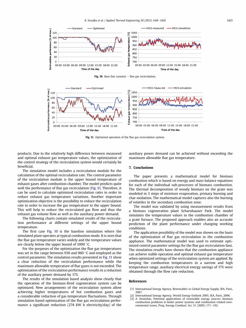
Fig. 10. Base line scenario e flue gas recirculation.
Fig. 11. Optimized operation of the flue gas recirculation system.
R. Strzalka et al. / Applied Thermal Engineering 50 (2013) 1418e1426 1425
products. Due to the relatively high difference between measuredand optimal exhaust gas temperature values, the optimization ofthe control strategy of the recirculation system would certainly bebeneficial.
The simulation model includes a recirculation module for thecalculation of the optimal recirculation rate. The control parameterof the recirculation module is the upper bound temperature ofexhaust gases after combustion chamber. The model predicts quitewell the performance of flue gas recirculation (Fig. 9). Therefore, itcan be used to calculate optimized recirculation rates in order toreduce exhaust gas temperature variations. Another importantoptimization objective is the possibility to reduce the recirculationrate in order to increase the gas temperature to the upper bound.This will help to reduce the recirculated gas flow and thus theexhaust gas volume flow as well as the auxiliary power demand.
The following charts contain simulated results of the recircula-tion performance at different settings of the upper boundtemperature.
The first case Fig. 10 is the baseline simulation where thesimulated plant operates at typical combustionmode. It is seen thatthe flue gas temperature varies widely and the temperature valuesare clearly below the upper bound of 1000 �C.
For the purposes of the optimization the flue gas temperatureswas set in the range between 930 and 960 �C and employed as thecontrol parameter. The simulation results presented in Fig. 11 showa clear reduction of the recirculation performance while themaximum allowable temperature of flue gases is not exceeded. Theoptimization of the recirculation performance results in a reductionof the auxiliary power demand by 17%.
The results of the simulation based analysis show clearly thatthe operation of the biomass-fired cogeneration system can beoptimized. New arrangements of the recirculation system allowachieving higher temperatures of hot combustion gases anda considerable reduction of gas temperature fluctuations. Throughsimulation based optimization of the flue gas recirculation perfor-mance a significant reduction (274 kW h electricity/day) of the
auxiliary power demand can be achieved without exceeding themaximum allowable flue gas temperature.
7. Conclusions
The paper presents a mathematical model for biomasscombustion which is based on energy and mass balance equationsfor each of the individual sub-processes of biomass combustion.The thermal decomposition of woody biomass on the grate wasmodeled in 3 steps of moisture evaporation, primary burning andchar oxidation. The mathematical model captures also the burningof volatiles in the secondary combustion zone.
The model was validated by using measurement results froma biomass cogeneration plant Scharnhauser Park. The modelsimulates the temperature values in the combustion chamber ofa grate furnace. The proposed approach enables also an accurateprediction of the plant performance under changing workingconditions.
The application possibility of the model was shown on the basisof the optimization of flue gas recirculation in the combustionappliance. The mathematical model was used to estimate opti-mized control parameter settings for the flue gas recirculation fans.The simulation results have shown that the combustion appliancecan achieve stable operation and optimal exhaust gas temperaturewhen optimized settings of the recirculation system are applied. Bykeeping the combustion temperatures in a narrow and hightemperature range, auxiliary electrical energy savings of 17% wereobtained through the flow rate reduction.
References
[1] International Energy Agency, Renewables in Global Energy Supply, IEA, Paris,2007.
[2] International Energy Agency, World Energy Outlook 2005, IEA, Paris, 2006.[3] A. Demirbas, Potential applications of renewable energy sources, biomass
combustion problems in boiler power systems and combustion related envi-ronmental issues, Prog. Energy Combust. Sci. 31 (2005) 171e192.

R. Strzalka et al. / Applied Thermal Engineering 50 (2013) 1418e14261426
[4] I. Obernberger, Reached Development in Biomass Combustion Technologiesand Future Outlook, 17th European Biomass Conference, Hamburg, Germany,July 2009, 20e37.
[5] J. Kalina, Integrated biomass gasification combined cycle distributed genera-tion plant with reciprocating gas engine and ORC, Appl. Therm. Eng. 31 (2011)2829e2840.
[6] M. Garderer, G. Gallmetzer, H. Spliethoff, Biomass fired hot air gas turbinewith fluidized bed combustion, Appl. Therm. Eng. 30 (2010) 1594e1600.
[7] F. Biedermann, I. Obernberger, Ash-related problems during biomass combus-tion and Possibilities for a Sustainable ash Utilisation, International ConferenceWorld renewable energy Congress, Aberdeen, UK, May 2005, 120e124.
[8] T. Madhiyannon, P. Sathitruangsak, S. Soponronnarit, Combustion character-istics of rice-husk in a short-combustion-chamber fluidized-bed combustion(SFBC), Appl. Therm. Eng. 30 (2010) 347e353.
[9] M. Leskens, L.B.M. Van Kessel, O.H. Bosgra, Model predictive control as a toolfor improving the process operation of MSW combustion plants, WasteManage. 25 (2005) 788e798.
[10] R. Strzalka, R. Ulbrich, U. Eicker, Modeling of Grate Combustion in an ORCCogeneration Plant, 18th European Biomass Conference, Lyon, France, May2010, 1347e1351.
[11] D. Shin, C. Sangmin, The combustion of simulated waste particles in a fixedbed, Combust. Flame 121 (2000) 167e180.
[12] R. Bauer, M. Gölles, T. Bruner, N. Dourdoumas, I. Obernberger, Modeling ofgrate combustion in a medium scale biomass furnace for control purposes,Biomass Bioenergy 34 (2010) 417e427.
[13] P. Dare, J. Gifford, R.J. Hooper, A.H. Clemens, L.F. Damiano, D. Gong,T.W. Matheson, Combustion performance of biomass residue and purposegrown species, Biomass Bioenergy 21 (2001) 277e287.
[14] A. Faaij, Modern biomass conversion technologies, Mitigation AdaptationStrateg. for Glob. Change 11 (2006) 343e375.
[15] Th. Nussbaumer, Combustion and co-combustion of biomass: fundamentals,technologies and primary Measures for emission reduction, Energy Fuels 17(2003) 1510e1521.
[16] R. Johansson, H. Thunman, B. Leckner, Influence of intraparticle gradients inmodelling of fixed bed combustion, Combust. Flame 149 (2007) 49e62.
[17] R. Strzalka, R. Ulbrich, U. Eicker, Proposal for a model of biomass combustionin a grate furnace, Chem. Process Eng. 4 (2010) 74e75.
[18] M. Roman, E. Bobasu, D. Selisteanu, Modelling of biomass combustion process,Energy Procedia 6 (2011) 432e440.
[19] P. Venturini, D. Borello, C. Iossa, D. Lentini, F. Rispoli, Modelling of multiphasecombustion and deposit formation in a biomass-bed furnace, Energy 35(2010) 3008e3021.
[20] J. Collazo, J. Porteiro, D. Patino, E. Granada, Numerical modelin of thecombustion of densified wood under fixed-bed conditions, Fuel (2011).doi:10.1016/j.fuel.2011.09.044.
[21] Y.B. Yang, V.N. Sharifi, J. Swithenbank, Converting moving grate incinerationfrom combustion to gasification e numerical simulation of the burningcharacteristics, Waste Manage. 27 (2007) 645e655.
[22] C. Yin, A.L.A. Rosendahl, S.K. Kaer, Grate-firing of biomass for heat and powerproduction, Prog. Energy Combust. Sci. 34 (2008) 725e754.
[23] S. Van Loo, J. Koopejan, The Handbook of Biomass Combustion and Co-firing,Earthscan, London, England, 2008.
[24] Y.B. Yang, V.N. Sharifi, J. Swithenbank, Effect of air flow rate and fuel moistureon the burning behaviors of biomass and simulated solid wastes in a packedbed, Fuel 82 (2003) 1553e1562.
[25] Y.B. Yang, C. Ryu, A. Khor, N.E. Yates, V.N. Sharifi, J. Swithenbank, Effect of fuelproperties on biomass combustion e part II. modelling approach e identifi-cation of the controlling factors, Fuel 84 (2005) 2116e2130.
[26] H. Thunman, B. Leckner, Co-current and counter-current fixed bed combus-tion of biofuel e a comparison, Fuel 82 (2003) 275e283.
[27] C. Ryu, Y.B. Yang, A. Khor, N.E. Yates, V.N. Sharifi, J. Swithenbank, Effect of fuelproperties on biomass combustion: part I. experiments e fuel type, equiva-lence ratio and particle size, Fuel 85 (2006) 1039e1046.
[28] J.J. Saastamoinen, R. Taipale, M. Horttanainen, P. Sarkomaa, Propagation of theignition front in bed of particles, Combust. Flame 149 (2000) 214e226.
[29] R.P. Van der Lans, L.T. Pedersen, A. Jensen, P. Glarborg, K. Dam-Johansen,Modelling and experiments of straw combustion in a grate furnace, BiomassBioenergy 19 (2000) 199e208.
[30] Y.B. Yang, H. Yamauchi, V. Nasserzadeh, J. Swithenbank, Effects of fuel devo-latilisation on the combustion of wood chips and incineration of simulatedmunicipal solid wastes in a packed bed, Fuel 82 (2003) 2205e2221.
[31] H. Walter, Sustainable Energy Systems (In German), ViewegþTeubner,Wiesbaden, Germany, 2009.
[32] H. Zhou, A.D. Jensen, P. Glarborg, P.A. Jensen, A. Kavaliauskas, Numericalmodeling of straw combustion in a fixed bed, Fuel 84 (2005) 389e403.
[33] Th. Nussbaumer, Reduction of pollutant emissions from wood combustion(in German), PhD Thesis Swiss Federal Institute of Technology Zürich,Switzerland 1989.
[34] R. Strzalka, R. Ulbrich, U. Eicker, Modeling of grate combustion in an ORCcogeneration plant, International Symposium on heat transfer and renewablesources of energy, Miedzyzdroje, Poland, September 2010, 267e274.
[35] D. Menghini, F.S. Marra, C. Allouis, F. Beretta, Effect of excess air on theoptimisation of heating appliances for biomass combustion, Exp. Therm. FluidSci. 32 (2008) 1371e1380.
Copyright © 2022 FDOKUMEN