Analysis and Design of Buildings with Added Energy Dissipation Systems
22
103 Research Objectives This article is a summary of the progress made during 2000-2001 by MCEER researchers working in the subtask of facilitating technologies. These research progresses should be viewed from the context that the long term (3-4 year) objective is to complete an MCEER monograph on Analysis and Design of Buildings with Added Energy Dissipation Sys- tems. Although each individual researcher is advancing the state-of-the- art knowledge with his respective graduate students and research collaborators, it is the total systems integrated effort directed toward the practicing professional that underpins the projects within this group. This undertaking is possible by using the “Center Approach” in earthquake engineering research. Analysis and Design of Buildings with Added Energy Dissipation Systems by Michael C. Constantinou, Gary F. Dargush, George C. Lee (Coordinating Author), Andrei M. Reinhorn and Andrew S. Whittaker National Science Foundation, Earthquake Engineering Research Centers Program M CEER’s research program 2 on the seismic retrofit of hospitals concen- trates on developing cost-effective retrofit strategies for critical fa- cilities using new and emerging materials and enabling technologies. Current emphasis is given to hospitals that should remain functional dur- ing and immediately after damaging and/or destructive earthquakes. The major disciplinary components of this program are geotechnical, structural, nonstructural, advanced technologies and high performance materials, socio-economic issues and systems integration. One important research task concerning the methods of analysis and design of buildings with added emerging materials (e.g., composite infill walls) and/or en- abling technologies (e.g., damping devices) is carried out by a group of research investigators under the title “Facilitating Technologies.” This task is the heart of the systems integrated approach concerning the perfor- mance of a system (i.e., the performance of hospital buildings and con- tents with added earthquake protective systems so that the medical functions can be carried out). To develop retrofit strategies for buildings by using added materials and/or enabling devices, practicing engineers need to know how to choose appropriate technologies to satisfy building performance indices and/or objectives cost-effectively for given earthquake risk. In view of FEMA 273/274 and NEHRP 2000, which encourage the Michael C. Constantinou, Professor and Chair, Department of Civil, Structural and Environmental Engineering, University at Buffalo, Panos Tsopelas, Assistant Professor, Catholic University of America, Wilhelm Hammel, Senior Consultant, KPMG, Germany, and Ani N. Sigaher, Ph.D. candidate, Department of Civil, Structural and Environmental Engineering, University at Buffalo Gary F. Dargush, Associate Professor. Ramesh Sant, Ph.D. Candidate, and Rajesh Radhakrishnan, Graduate Student, Department of Civil, Structural and Environmental Engineering, University at Buffalo Research Team continued on page 2
-
Upload
independent -
Category
Documents
-
view
0 -
download
0
Transcript of Analysis and Design of Buildings with Added Energy Dissipation Systems

103
Research Objectives
This article is a summary of the progress made during 2000-2001 byMCEER researchers working in the subtask of facilitating technologies.These research progresses should be viewed from the context that thelong term (3-4 year) objective is to complete an MCEER monograph onAnalysis and Design of Buildings with Added Energy Dissipation Sys-tems. Although each individual researcher is advancing the state-of-the-art knowledge with his respective graduate students and researchcollaborators, it is the total systems integrated effort directed toward thepracticing professional that underpins the projects within this group. Thisundertaking is possible by using the “Center Approach” in earthquakeengineering research.
Analysis and Design of Buildings withAdded Energy Dissipation Systems
by Michael C. Constantinou, Gary F. Dargush, George C. Lee (Coordinating Author), Andrei M. Reinhornand Andrew S. Whittaker
National Science Foundation,Earthquake EngineeringResearch Centers Program
MCEER’s research program 2 on the seismic retrofit of hospitals concen-trates on developing cost-effective retrofit strategies for critical fa-
cilities using new and emerging materials and enabling technologies.Current emphasis is given to hospitals that should remain functional dur-ing and immediately after damaging and/or destructive earthquakes.
The major disciplinary components of this program are geotechnical,structural, nonstructural, advanced technologies and high performancematerials, socio-economic issues and systems integration. One importantresearch task concerning the methods of analysis and design of buildingswith added emerging materials (e.g., composite infill walls) and/or en-abling technologies (e.g., damping devices) is carried out by a group ofresearch investigators under the title “Facilitating Technologies.” This taskis the heart of the systems integrated approach concerning the perfor-mance of a system (i.e., the performance of hospital buildings and con-tents with added earthquake protective systems so that the medicalfunctions can be carried out). To develop retrofit strategies for buildingsby using added materials and/or enabling devices, practicing engineersneed to know how to choose appropriate technologies to satisfy buildingperformance indices and/or objectives cost-effectively for given earthquakerisk. In view of FEMA 273/274 and NEHRP 2000, which encourage the
Michael C. Constantinou,Professor and Chair,Department of Civil,Structural andEnvironmentalEngineering, University atBuffalo, Panos Tsopelas,Assistant Professor,Catholic University ofAmerica, WilhelmHammel, SeniorConsultant, KPMG,Germany, and Ani N.Sigaher, Ph.D. candidate,Department of Civil,Structural andEnvironmentalEngineering, University atBuffalo
Gary F. Dargush, AssociateProfessor. Ramesh Sant,Ph.D. Candidate, andRajesh Radhakrishnan,Graduate Student,Department of Civil,Structural andEnvironmentalEngineering, University atBuffalo
Research Teamcontinued on page 2

104
use of emerging technologies toachieve building performance ob-jectives, there is a need to developprinciples and design guidelines forthese engineers. This is the funda-mental rationale of the researchtask on facilitating technologies.
MCEER investigators have mademany key contributions to the twomost advanced codes and guide-lines related to the implementationof passive energy dissipation sys-tems: FEMA 273/274 Guidelinesfor the Seismic Rehabilitation ofBuildings, published in 1998, andthe NEHRP 2000 Guidelines forSeismic Regulations for NewBuildings and Other Structures,that will be published in the nextfew months.
The FEMA 273 Guidelines and274 Commentary represented theculmination of more than a decadeof work funded by the FederalEmergency Management Agency,the National Science Foundationand other agencies. These docu-ments provide structural engineerswith new information on proce-dures for the analysis, evaluation,and design of existing and retrofitconstruction. Information is alsopresented on performance-basedearthquake engineering, modelingand analysis, steel, concrete, andtimber structures, foundations,
and nonstructural components.MCEER researchers have contrib-uted to FEMA 273/274 in two ar-eas: modeling and analysis, andseismic isolation and damping sys-tems (see Constantinou et al., 1998and Tsopelas et al., 1997).
The 2000 NEHRP RecommendedProvisions for Seismic Regulationsfor New Buildings and Other Struc-tures includes robust procedures forthe analysis and design of passive en-ergy dissipation systems (Appendixto Chapter 13) using force-basedmethods of analysis that are consis-tent with those methods used for theanalysis and design of conventionalconstruction. The development offorce-based analysis and component-checking methods for highly nonlin-ear or velocity-dependent energydissipation devices proved to be amost demanding task. MCEER re-searchers have developed the tech-nical underpinnings of the methodspresented in NEHRP 2000 (seeRamirez et al., 2000).
Since the publication of FEMA273/274 in 1998, many practicingengineers have been interested inusing these guidelines to retrofitexisting buildings with base isola-tion and/or energy dissipation de-vices. As a result, several majorretrofit projects have been com-pleted and their results publicized,
George C. Lee, Director,MCEER, and Samuel P.Capen Professor ofEngineering, Departmentof Civil, Structural andEnvironmentalEngineering, University atBuffalo, Mai Tong, SeniorResearch Scientist, MCEERYihui Wu, ResearchScientist, MCEER,and WeiLiu, Ph.D. candidate,Department of Civil,Structural andEnvironmentalEngineering, University atBuffalo
Andrei Reinhorn, Professor,Department of Civil,Structural andEnvironmentalEngineering, University atBuffalo, KatrinWinkelmann,VisitingResearch Associate,Department of Civil,Structural andEnvironmentalEngineering, University atBuffalo from the Universityof Darmstadt andMettupalayamSivaselvan, Ph.D.candidate, Department ofCivil, Structural andEnvironmentalEngineering, University atBuffalo
Andrew S. Whittaker,Associate Professor, OscarRamirez, GraduateStudent, and Juan Gomez,Graduate Student,Department of Civil,Structural andEnvironmentalEngineering, University atBuffalo
Structural engineers who develop cost-effective retrofit de-signs for existing buildings will find information regardinghow to select the best passive energy dissipation device sys-tem for a given type of building (e.g., high rise, low-mediumheight, steel, reinforced concrete, masonry, timber, rela-tively symmetrical, irregularly-shaped, etc.) and for givenearthquake risk very useful. Other procedures, such as howto optimally distribute damping devices throughout a struc-ture and how to consider multi-performance indices are alsoof critical importance.

105Analysis and Design of Buildings with Added Energy Dissipation Systems
particularly in the area of base iso-lation systems, in which MCEERresearchers (most notably, M.Constantinou and A. Whittaker)have acted as consultants. Becausebase isolation technology has alonger history of practical imple-mentation for buildings andbridges, more projects have beensuccessfully completed. However,only limited reports are available inthe open literature on passive en-ergy dissipation devices applied tobuildings. This is primarily due tothe relatively short history in ex-perience of practical applicationsand the fact that many availabledevices/approaches are reported inresearch publications, many devel-oped and/or improved by MCEERresearchers.
During the past two decades,many advances have been reportedon the performance and vibrationreduction properties of passiveenergy devices. As noted earlier,MCEER researchers have played asignificant role in the developmentof a variety of devices. This “device-based” line of pursuit will be con-tinued as new ideas, materials and/or devices become available.
A new systems-based approach isnow being undertaken to provideanswers to the many questions onchoosing appropriate devices. Re-garded as the “building-device sys-tem based” consideration, thesestudies emphasize the perfor-mance of the building with addedpassive energy dissipation devices.This new systems-based approachis the central theme of the researchtask on facilitating technologies,and this paper focuses on thesenew approaches.
To develop analytical models orto carry out experimental observa-tions for the systems-based study
is considerably more complicatedthan to model or to test the behav-ior of a single device.
First, existing buildings them-selves have different dynamic char-acteristics and are complicated tomodel. The performance of thedevices cannot be generalizedbased on one simple structure.Many multiple degree of freedom(MDOF) systems cannot be treatedas single DOF systems (decouplingassumption) with sufficient accu-racy. To develop simplified finiteelement (FE) analysis models forcomplicated MDOF systems is itselfa challenge.
When energy dissipation devicesare implemented in these MDOFstructures, the total building-devicesystems are generally nonlinear sys-tems. Much creativity and funda-mental research in structuraldynamics principles have to be pur-sued to develop a reasonablysimple and accurate analysis anddesign procedure. The current,MCEER studies may be groupedinto three separate categories.
Type I Projects: New Devices andSystems —continued developmentof new ideas in passive energy dis-sipation devices and semi-activesystems. The semi-active systemscan extend the range of traditionalpassive energy dissipation systemsand can be combined to providean added fail-safe feature to thesesystems.
Type II Projects: MDOF Modelingof Building-Device Systems—This cat-egory of studies is concerned withthe behavior and design of thebuilding-device system that mustbe studied by using multiple DOFmodels, including when the sys-tems are nonproportionallydamped. These studies providequantitative information on the er-
• Martin Johnson,GroupManager, EQEInternational
• Ali Karakaplan,President, LARSA, Inc.
• Charles Kircher,Principal, Charles Kircherand Associates
• Douglas Taylor,President, Taylor Devices,Inc.
• U.S. Department ofCommerce

106
rors when such buildings are ap-proximated by decoupled singleDOF systems.
Type III Projects: Analysis and De-sign Software—MCEER will con-tinue its development of analysisand design software for buildingswith added energy dissipation sys-tems. Some projects are fundamen-tal in nature to establish newapproaches while others empha-size the development of user-friendly simplified procedures fordesign professionals with accept-able accuracy.
The findings from research inthese three categories will culmi-nate in a monograph on Analysisand Design of Buildings withAdded Energy Dissipation Systemfor the design professional. Thefollowing sections provide brief de-scriptions of the progress made incurrent projects.
Scissor-Jack SeismicEnergy DissipationSystem(Type I Project)
Energy dissipation systems arebeing employed in the UnitedStates to provide enhanced protec-tion for new and retrofit buildingand bridge construction. The hard-ware utilized includes yielding steeldevices, friction devices, viscoelas-tic solid devices and mostly, so far,viscous fluid devices.
Engineers are familiar with andhave extensively used diagonal andchevron brace configurations for thedelivery of forces from energy dissi-pation devices to the structuralframe (Soong and Dargush, 1997;Constantinou et al., 1998). New con-figurations have been developed
which offer certain advantages, eitherin terms of cost of the energy dissi-pation devices, or in terms of archi-tectural considerations such as openspace requirements. Particularly, stiffstructural systems under seismicload or structural systems underwind load undergo small drift andthe required damping forces arelarge. This typically results in largerdamping devices and accordingly,greater cost. In other cases, energydissipation devices cannot be usedin certain areas due to open spacerequirements and the ineffective-ness of damping systems wheninstalled at near-vertical configura-tions.
Two recently developed configu-rations, the toggle-brace and thescissor-jack energy dissipation sys-tem configurations, offer advan-tages that overcome theselimitations. Both utilize innovativemechanisms to amplify displace-ment and accordingly lower forcedemand in the energy dissipationdevices. However, they are morecomplex in their application sincethey require more care in theiranalysis and detailing. The theoryand development of these systemshas been described inConstantinou et al. (2001) andConstantinou and Sigaher (2000).This section briefly presents thesenew configurations and comparesthem with the familiar chevronbrace and diagonal configurations.
The toggle-brace and scissor-jacksystems are configurations for mag-nifying the damper displacementso that sufficient energy is dissi-pated with a reduced requirementfor damper force. Conversely, theymay be viewed as systems for mag-nifying the damper force throughshallow truss configurations and
Program 2: Seismic Retrofit ofHospitals
• Task 2.4a TechnologyPortfolio – Structural

107Analysis and Design of Buildings with Added Energy Dissipation Systems
then delivery of the magnifiedforce to the structural frame.
Figure 1 illustrates variousdamper configurations in a framingsystem. Let the interstory drift beu, the damper relative displace-ment be u
D , the force along the axis
of the damper be FD and the damp-
ing force exerted on the frame beF. It may be shown that
u uD = f (1)
F FD= f (2)
where ƒ = magnification factor.Expressions for the magnificationfactor of various configurations areshown in Figure 1. The significanceof the magnification factor may bebest demonstrated in the case oflinear viscous dampers, for which
F C uD o D= ˙ (3)
where ̇uD= relative velocity be-
tween the ends of the damperalong the axis of the damper. Thedamping ratio under elastic condi-tions for a single-story frame (asshown in Figure 1) with weight, W,and fundamental period, T, is:
βπ
= C gT
Wo f
2
4(4)
That is, the damping ratio is pro-portional to the square of the mag-nification factor. The toggle-braceand scissor-jack systems canachieve magnification factorslarger than unity. The systems canbe typically configured to have val-ues ƒ = 2 to 3 without any signifi-cant sensitivity to changes in thegeometry of the system. By con-trast, the familiar chevron-brace
and diagonal configurations have ƒless than or equal to unity.
For the purpose of comparison,consider the case of the use of alinear viscous damper with C
o =160
kN-s/m (= 0.9 kip-s/in) in the fram-ing systems of Figure 1 with weightW = 1370 kN (= 308 kip) and T =0.3 second. The resulting dampingratios are shown in Figure 1. Theeffectiveness of the toggle-braceand scissor-jack systems is clearly
MCEER Users Network:http://civil.eng.buffalo.edu/
users_ntwk
IDARC Users Group:http://civil.eng.buffalo.edu
Dia
go
na
lF
W
θCo
u
θcosf =
Ch
evro
n
Wu
F
Co001.f =
Lo
we
rT
og
gle
u
F
W
Coθ1
2θ
°90
)cos(
sin
21
2
θθθ+
=f
Up
pe
rT
og
gle
90
u
F
W
Co
θ2
θ1
°1
21
2 θθθ
θsin
)cos(
sinf +
+=
Re
ve
rse
To
gg
le
W
θ oC1
θ2
u
F
90
α
°
2
21
1 cos)cos(
cos θθθ
θα −+
=f
Scis
so
r-Ja
ck
3tan
cos
θψ=f
Ψ
θ3
Co
u
F
W
■ Figure 1. Effectiveness of Damper Configurations in Framing Systems
108
demonstrated. It should be notedthat the configurations for thesetwo systems are identical to thosetested at the University at Buffalo.
It is clear in the results of Figure 1and in equations (1), (2) and (4) thatthe toggle-brace and scissor-jack con-figurations may provide substantialenergy dissipation capability with theuse of low output force devices. Thismay result in an important cost ad-vantage in systems that undergosmall drifts such as stiff structuralsystems under seismic load and moststructural systems under wind load.Such cases of small drift lead to a re-quirement for increased volume offluid viscous devices and accordinglyincreased cost. The use of the newconfigurations eliminates the neces-sity for large volume damping de-vices and may result in reduced cost.
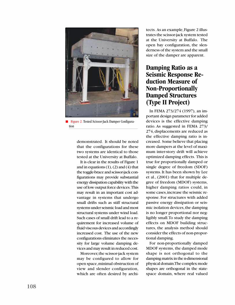
Moreover, the scissor-jack systemmay be configured to allow foropen space, minimal obstruction ofview and slender configuration,which are often desired by archi-
tects. As an example, Figure 2 illus-trates the scissor-jack system testedat the University at Buffalo. Theopen bay configuration, the slen-derness of the system and the smallsize of the damper are apparent.
Damping Ratio as aSeismic Response Re-duction Measure ofNon-ProportionallyDamped Structures(Type II Project)
In FEMA 273/274 (1997), an im-portant design parameter for addeddevices is the effective dampingratio. As suggested in FEMA 273/274, displacements are reduced asthe effective damping ratio is in-creased. Some believe that placingmore dampers at the level of maxi-mum inter-story drift will achieveoptimized damping effects. This istrue for proportionally damped orsingle degree of freedom (SDOF)systems. It has been shown by Leeet al., (2001) that for multiple de-gree of freedom (MDOF) systems,higher damping ratios could, insome cases, increase the seismic re-sponse. For structures with addedpassive energy dissipation or seis-mic isolation devices, the dampingis no longer proportional nor neg-ligibly small. To study the dampingeffects on MDOF building struc-tures, the analysis method shouldconsider the effects of non-propor-tional damping.
For non-proportionally dampedMDOF systems, the damped modeshape is not orthogonal to thedamping matrix in the n-dimensionalphysical domain. The complex modeshapes are orthogonal in the state-space domain, where real valued
■ Figure 2. Tested Scissor-Jack Damper Configura-tion

109Analysis and Design of Buildings with Added Energy Dissipation Systems
modal superposition methods can-not be directly applied. The “doublemodal superposition” approach de-veloped by Gupta and Law (1986) isused in this analysis, where the re-sponse is the superposition of “modaldisplacement” and “modal velocity.”These modes are not the un-dampedsystem modes, nor the complex sys-tem modes. The conventional modalanalysis routine of fast calculationcan be used in this approach and thedamping effects can be more readilyexplained by using structural dy-namic parameters.
Theoretical Background
In a proportionally damped sys-tem, the damping ratio is used todescribe damping effects. However,damping can affect the response ofan MDOF non-proportionallydamped system in many ways, in-cluding modal response, modalshape and natural frequencies, anddamping ratio.
For an MDOF system subjectedto earthquake excitation, the equa-tion of motion can be written as:
M U C U KU MU.. . ..
+ + = − b gu (5)
where M, C and K denote mass,damping and stiffness matrices, re-spectively; U is the relative displace-ment vector; U
b is a displacement
vector obtained by statistically dis-placing the support by unity in thedirection of the input motion; andu
g is the ground displacement.The double modal superposition
method obtains the response byequation (6):
, i U U U U U= = −∑ i
i
N
i id v
(6)
U Uid
id
i iv
iv
iX X= =ψ ψ , .
(7)
where U id and U i
v are real
value response associated with themodal shape, as defined by equa-
tion (8), and ψ id and ψ i
v are dis-
placement and velocity modeshapes, respectively. They are realvalue mode shapes and are calcu-lated by the state vector eigen-equa-tion. These mode shapes aredetermined not only by the systemmass and stiffness but also by theadded damping matrix. In somecases, the added damping willdominate the mode shapes (aswhen the fundamental modalshape collapse due to added damp-ing.). X
i is the modal response of
the following “modal” equation.In equation (8), ζ
i and ω
i are the
“modal damping ratio and circularfrequency of mode i”, and u
g is the
ground motion.•• •
˙̇X X X ui i gi i i + + = −2 2
iζ ω ω (8)
The damping ratio and naturalcircular frequency ζ
i, ω
i in the
above equation are determined bythe complex state vector eigen-value solution, like the mode shape.Because the state vector will varyfor different damping devicesadded, the modal shape, circularfrequency and damping ratio willnot be constant. Thus, the systemresponse defined by equation (6)cannot be always reduced by in-creasing the damping ratio.
Case Studies
To illustrate how system charac-teristics change and their impact onseismic response due to addeddamping, a four DOF frame struc-ture was analyzed. The first two vi-
“The resultsfrom modelingand analysis ofa Californiahospitalbuilding willprovide theengineeringcommunity witha three-dimensionalnonlinearanalysisplatform thatcurrently doesnot exist.”

110
bration modes of the frame areshown in Figure 3.
The added damping was limitedto a maximum of 30% of the effec-tive damping ratio (defined inFEMA 273 as a proportional ratio).Fifty-two linear viscous damperconfigurations were examined. The52 configurations were arranged byconsidering all possible damperlocations and their combinations,then changing the damping param-eters to make the first modal effec-tive damping ratio 5%, 10%, 20%and 30% (damping ratio by the
added device plus 2%). As listed inTable 1, dampers were installed onevery floor independently, everytwo floors, every three floors or onall four floors. There were 13 dif-ferent damper configurations, withfour damping ratios.
As noted above, the first mode ofthe complex damping ratio may bedifferent from the first mode of thecontrolling effective damping ratio.The first complex modal dampingratio for all 52 cases is listed in Table2. For small damping ratios (5%),the complex damping ratio is al-most the same, however, when thedamping ratio is increased to 10%,case 4 shows a dramatic change,while the other cases stay the same.Cases 3, 4, 7, 10, and 12 have verydifferent values when the control-ling ratio increases to 20%. Finally,the first complex damping ratio forcases 1, 3, 4, 7 and 12 becomes 99%when the ratio is increased to 30%.
The change in natural frequencyin the first mode is given in Table3. Both damping ratio and fre-quency changes are related to themodal change for different damperconfigurations.
To illustrate the non-proportionalmode shape change, the first dis-
Case 1 2 3 4 5 6 7 8 9 10 11 12 131st story X X X X X X2nd story X X X X X X X3rd story X X X X X X X4th story X X X X X X
Flo
or
Mode 1
Mode 2
4
3
2
1
0-1 -0.5 0 0.5 1
Flo
or
Case 1 2 3 4 5 6 7 8 9 10 11 12 135% 0.05 0.05 0.05 0.04 0.05 0.05 0.05 0.05 0.05 0.05 0.05 0.05 0.0510% 0.10 0.10 0.10 0.99 0.10 0.10 0.09 0.10 0.10 0.10 0.10 0.10 0.1020% 0.16 0.20 0.13 0.99 0.20 0.20 0.13 0.20 0.20 0.20 0.20 0.99 0.2030% 0.99 0.28 0.99 0.99 0.31 0.31 0.99 0.30. 0.30 0.30 0.30 0.99 0.30
■ Table 2. Damping Ratio Comparison (First mode)
■ Table 1. Damper Location
■ Figure 3. First Two Modal Shapes

111Analysis and Design of Buildings with Added Energy Dissipation Systems
placement mode shape at the con-trolling effective damping ratios of5%, 10%, 20% and 30% are shownin Figure 4. The figure shows that,as the damping ratio becomeshigher, dramatic changes can resultin cases 1, 3, 4, 7 and 12 (the funda-mental mode collapsed). When thefundamental mode shape collapses,the second mode shape becomesdominant in the system response,as shown in Figure 5.
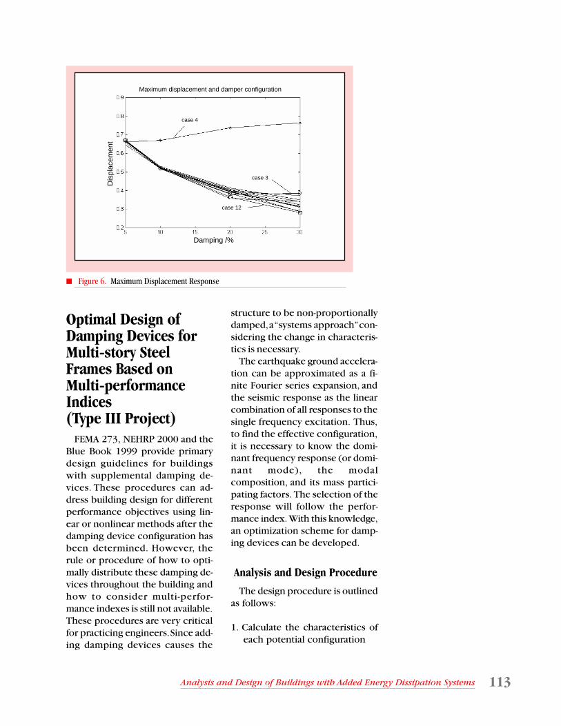
The relationship between themaximum displacement responseand the controlling effective damp-
ing is shown in Figure 6. Exceptfor case 4, the response decreasesas the damping ratio increases.When the controlling damping ra-tio is higher than 15%, differentdamper configurations will resultin different response reductionseven though they may achieve thesame effective damping ratio value.It may also be seen from the figurethat the maximum responses witha 30% effective controlling damp-ing ratio for some cases are higherthan those with 20%. Table 4 liststhe maximum displacement re-
Case 1 2 3 4 5 6 7 8 9 10 11 12 135% 2.03 2.02 2.03 2.05 2.02 2.02 2.03 2.02 2.02 2.02 2.02 2.03 2.0210% 2.06 2.04 2.07 1.17 2.03 2.07 2.02 2.03 2.03 2.03 2.03 2.05 2.0220% 2.22 2.12 2.24 0.50 2.06 2.07 2.23 2.03 2.07 2.08 2.09 2.14 2.0330% 1.96 2.29 1.50 0.32 2.12 2.15 1.41 2.04 2.14 2.17 2.20 1.30 2.04
Displacement Displacement
a) Damping = 5% b) Damping = 10%
c) Damping = 20% d) Damping = 30%
Mas
s no
.M
ass
no.
Mas
s no
.M
ass
no.
case 4
case 1case 4
case 12
case 3
case 7
case 12
case 4
■ Table 3. Natural Frequency Comparison (First mode)(in Hz)
■ Figure 4. Displacement Modal Shapes

112
sponses for these two damping ra-tio values, calculated for the ElCentro earthquake. As seen in thetable, the damping increases in twoways: the first is where the re-sponse increased after more damp-ers were added and theconfiguration was unchanged(cases 3 and 4). The second case iswhen more dampers are added indifferent locations and configura-tions, as shown in case 1 at 20%,case 3 at 30%, case 4 at 30% andthe rest of the cases are at 20%. Thisconclusion has also been obtainedusing other earthquake records,such as from the Northridge earth-quake.
Continuing Effort
It is important to understandthe limitations of using the damp-ing ratio as the key seismic re-sponse reduction measurement.For many non-proportionallydamped structures, the evaluationof performance should be basedon response history analysis. Inthis regard, a simple method tocope with the various non-pro-portional damping effects will bevaluable for engineering applica-tions. This team is currently at-tempting to develop such amethod.
Case 1 2 3 4 5 6 7 8 9 10 11 12 1320% 0.357 0.398 0.381 0.738 0.403 0.392 0.397 0.409 0.399 0.392 0.383 0.365 0.41430% 0.343 0.287 0.384 0.765 0.324 0.315 0.374 0.339 0.309 0.313 0.289 0.280 0.350
First 2 displacement modes for case 4 at 10% damping ratio
Mas
s no
.
Displacement
1st mode 1.17Hz, complex dampingratio=99%
2nd mode 2.09Hz, complexdamping ratio=4%
First 2 displacement modes for case 7 at 30% damping ratio
Mas
s no
.
Displacement
b) Case 7, 30% Damping Ratio
a) Case 4, 10% Damping Ratio
1st mode 1.41Hz, complexdamping=99%
2nd mode 2.35Hz, complexdamping=13%
First 2 displacement modes for case 12 at 30% damping ratio
Mas
s no
.
1st mode 1.30 Hz, complexdamping=99%
Displacement
2nd mode 2.37 Hz, complexdamping=21%
1st mode 1.30Hz, complexdamping=99%
2nd mode 2.37Hz, complexdamping=21%
c) Case 12, 30% Damping Ratio
■ Figure 5. Mode Collapse
■ Table 4. Maximum Displacement Response at the Top Level of the Frame Using Standard El Centro Earthquake Record
113Analysis and Design of Buildings with Added Energy Dissipation Systems
Optimal Design ofDamping Devices forMulti-story SteelFrames Based onMulti-performanceIndices(Type III Project)
FEMA 273, NEHRP 2000 and theBlue Book 1999 provide primarydesign guidelines for buildingswith supplemental damping de-vices. These procedures can ad-dress building design for differentperformance objectives using lin-ear or nonlinear methods after thedamping device configuration hasbeen determined. However, therule or procedure of how to opti-mally distribute these damping de-vices throughout the building andhow to consider multi-perfor-mance indexes is still not available.These procedures are very criticalfor practicing engineers. Since add-ing damping devices causes the
structure to be non-proportionallydamped, a “systems approach” con-sidering the change in characteris-tics is necessary.
The earthquake ground accelera-tion can be approximated as a fi-nite Fourier series expansion, andthe seismic response as the linearcombination of all responses to thesingle frequency excitation. Thus,to find the effective configuration,it is necessary to know the domi-nant frequency response (or domi-nant mode), the modalcomposition, and its mass partici-pating factors. The selection of theresponse will follow the perfor-mance index. With this knowledge,an optimization scheme for damp-ing devices can be developed.
Analysis and Design Procedure
The design procedure is outlinedas follows:
1. Calculate the characteristics ofeach potential configuration
Maximum displacement and damper configuration
Damping /%
Dis
plac
emen
t
case 12
case 3
case 4
■ Figure 6. Maximum Displacement Response
114
2. Compare these with the origi-nal structural system’s character-istics, and identify for eachconfiguration:a. Natural frequencies (Some
modes may collapse into eachother due to added damping.This is particularly criticalwhen damping becomes non-proportional. It follows thatthe natural frequencies maychange significantly.)
b. Modal damping ratio (100%critical damping usually im-plies a mode collapsed, whichmay be a problem for modalresponse reduction)
c. Mode shapesd. Modal loading factors (varia-
tion in this characteristics maystrongly influence the abso-lute acceleration response)
e. Phase differences between themodes.
3. For a mass point of interest,check which natural frequen-cies will contribute most in theresponse, by using sinusoidal ex-citations of different amplitudes.Examine each correspondingsteady state response vector toidentify the largest contributionvector. A general excitation canbe simplified as a sum of this si-nusoidal excitation of variousamplitudes, multiplied by cer-tain envelopes. Thus, the re-sponse will be dominated by thecombination of n basic vectors.
4. The vectors computed above canbe further split into modal contri-butions. In this regard, compari-sons can be made among modalshapes, loading factors, natural fre-quencies (which provides infor-mation on relative phase lags) anddamping ratios (which provide in-formation on dynamic amplifica-tion factors). This information
illustrates the modes that are im-portant in the response of a givenmass point.
5. The damping distribution maybe very different if the optimi-zation target is selected as thestory drift or acceleration. Thedrift response is dominated bythe major modes. Thus, with ahigher modal participation fac-tor and a higher damping ratio,the drift responses will be fur-ther reduced. This is not the casefor acceleration response, whichincludes more higher mode con-tributions.
6. For acceleration response, if adamper is placed between theith and i+1th floors, then the i+1th
f loor acceleration is usuallylower than the ith floor. In addi-tion, i-1th floor acceleration willbe lower than that of ith floor.
Case Study
An 11-story steel frame buildingstructure was used as an optimaldesign example. The building’stypical plan and north-south eleva-tion are shown in Figures 7 and 8.This building had been designedwith supplemental damping de-vices. The typical device configu-ration in the frame is shown inFigure 9. A total of 120 damperswere added to the building, with24 dampers on the first story, andgradually decreasing as the storyheight increases.
If the performance index is se-lected as optimal story drift, thefirst story mass contributes less tothe dominant mode of the systemresponse. Better results may beobtained if the dampers in thisstory are redistributed. The opti-mized distribution removes most ofthe devices from the first story, and

115Analysis and Design of Buildings with Added Energy Dissipation Systems
adds them to the 6th to 11th stories.The same total number of damp-ers is used as in the original damperdistribution. With this optimizeddistribution, the total system damp-ing is increased by 4%. More im-portantly, the damping ratio of thedominant mode is increased by19%, and the largest story drift,which occurred in the 6th floor, isreduced by an average of 11% for aseries of spectra-compatible earth-quake. If the performance index isselected as acceleration, the opti-mal distribution will be different.
Current Efforts
The design and analysis proce-dure proposed here is based on fre-quency domain analysis and timedomain verification. Since responsespectrum or time history analysisare preferred in structural design,the method is currently being im-proved and optimized using re-sponse spectrum-based objectivefunctions.
ComputationalAseismic Design andRetrofit for PassivelyDamped Structures(Type III Project)
Over the past two decades, con-siderable effort has been directedtoward the development and en-hancement of protective systemsfor the control of structures underseismic excitation. In the area ofpassive energy dissipation systems,applications typically involve me-tallic yielding dampers, frictiondampers, viscous fluid dampers orviscoelastic dampers (e.g., Soongand Dargush, 1997; Constantinouet. al., 1998). Although the intro-duction of these new concepts andsystems presents the structural en-gineer with additional freedom inthe design process, many questionsalso naturally arise. In the case ofpassive energy dissipation systems,these questions range from perfor-mance and durability issues to con-cerns related to the sizing andplacement of damping elements.
One promising direction for fu-ture research involves the furtherdevelopment of the FEMA 273/274
■ Figure 7. Floor Frame Plan ■ Figure 8. Elevation Frame Plan ■ Figure 9. Damper Distribution

116
and NEHRP 2000 design guidelinesbased upon additional numericalsimulations and practical experi-ence. Alternatively, one may envi-sion a dramatically different designprocess for passively damped struc-tures by adopting a computationalapproach. Such an approachshould incorporate the dynamics ofthe problem, the uncertainty of theseismic environment, the reliabilityof the passive elements and per-haps also some key socioeconomicfactors. With these requirementsin mind, one can conceptualizeaseismic design as a complex adap-tive system and begin to develop ageneral computational frameworkthat promotes the evolution of ro-bust, and possibly innovative, de-signs.
Complex Adaptive Systems
There is a broad class of systemsin nature and in human affairs thatinvolve the complicated interac-tion of many components or agents.These may be classified as complexsystems, particularly when the in-teractions are predominantly non-linear. Within this class are systemswhose agents tend to aggregate ina hierarchical manner in responseto an uncertain or changing envi-ronment. These systems have theability to evolve over time and toself-organize. In some cases, thesystem may acquire collectiveproperties through adaptation thatcannot be exhibited by individualagents acting alone. Key character-istics of these complex adaptivesystems are nonlinearity, aggrega-tion, flows and diversity (Holland,1995). Examples include the hu-man central nervous system, thelocal economy, a rain forest or amultidisciplinary research center.
Holland (1962, 1992) also devel-oped a unified theory of adaptationin both natural and artificial sys-tems. In particular, Holland broughtideas from biological evolution tobear on the problem. Besides pro-viding a general formalism forstudying adaptive systems, this ledto the development of genetic al-gorithms.
Computational Framework forAseismic Design
With these ideas, one can nowenvision a new aseismic designapproach based upon the creationof an artificial complex adaptivesystem. The primary research ob-jective is to develop an automatedsystem that can evolve robust de-signs under uncertain seismic en-vironments. With continueddevelopment, the system may alsobe able to provide some novel so-lutions to a range of complexaseismic design problems.
Figure 10 depicts the overall ap-proach for computational aseismicdesign and retrofit (CADR), borrow-ing terminology from biologicalevolution. Design involves a se-quence of generations within a se-quence of eras. In each generation,a population of individual struc-tures is defined and evaluated inresponse to ground motion realiza-tions. Cost and performance areused to evaluate the fitness, whichin turn determines the makeup ofthe next generation of structures.Performance is judged by perform-ing nonlinear transient dynamicanalysis. Presently, this analysis uti-lizes either ABAQUS (2000) or anexplicit state-space transient dy-namics code (tda). The implemen-tation of the genetic algorithm

117Analysis and Design of Buildings with Added Energy Dissipation Systems
controlling the design evolution isaccomplished within the public-domain code Sugal (Hunter, 1995).
Model Problem: Five-StorySteel Moment Frame
Consider an example of a five-story steel moment frame retrofitwith passive energy dissipators asshown in Figure 11. Three differ-ent types of dampers are available:metallic plate dampers, linear vis-cous dampers, and viscoelasticdampers. For each type, five dif-ferent sizes are possible. Conse-quently, a 20-bit genetic code isemployed to completely specifythe dampers used in each story ofany particular structure A∈α . Thus,for this problem, the set α contains220 (i.e., more than one million)possible structures. Figure 11 alsodefines a hierarchical approach inwhich different structural modelswith varying levels of complexityare utilized in each era. The idea isto first use simple models to widelyexplore the design space and thento employ more complicated andcomputationally expensive models
later in the design process. Cur-rently, a two-surface cyclic plastic-ity model is applied for the primarystructural system and metallic platedampers, while a coupledthermoviscoelastic model with in-elastic heat generation is used forthe viscoelastic dampers. Bothinterstory drift and story accelera-tion limits are set in order to estab-lish acceptable performance.
As a specific example, considerthe application of the CADR strat-egy to a typical five-story steel mo-ment frame based upon Era 1 (i.e.,
Computational Aseismic Design and Retrofit
Evaluate Era
Evaluate Generation
Evaluate Individual Structure
Define StructureRealize
Ground Motion(s)
Determine CostEvaluate Performance
(abaqus or tda)
Determine Fitness
SEQUENTIAL
PARALLEL
Computational Aseismic Design and Retrofit
Example: Five-story steel moment frame retrofit w/passive energy dissipators
Problem Definition:
2nd Era3rd Era
1st Era
…
Genetic Code 20-bit design descriptor
xxyy xxyy xxyy xxyy xxyy
Story: 1 2 3 4 5
xx =
00 None/Size A
01 Metallic
10 Viscous
11 VE
yy =
00 Size B
01 Size C
10 Size D
11 Size E
Example: Five-story steel moment frame retrofit w/passive energy dissipators
Problem Definition:
1st Era 2nd Era 3rd Era
Genetic Code 20-bit design Descriptor
Story: 1 2 3 4 5
00 None/Size A01 Metallic10 Viscous11 VE
00 Size B01 Size C10 Sise D11 Size E
xx = yy =xxyy xxyy xxyy xxyy xxyy
■ Figure 10. Overall Framework for Computational Aseismic Design andRetrofit
■ Figure 11. Problem Definition for Five-story Steel Moment Frame

118
lumped parameter) simulations.Let k
i and Wi represent the ith story
elastic stiffness and story weight,respectively. The baseline framemodel has uniform story weightsW
i =W =125 kips for i =1,2,...5 and
story stiffness k1=k
2=k
3 =193 kip/in,
k4 =147kip/in,k5 =87 kip/in. The
first two natural frequencies are1.07 Hz and 2.72 Hz. A two-surfacecyclic plasticity model is employedto represent the hysteretic behav-ior of the primary structure.
A retrofit strategy is now devel-oped to protect this structure situ-ated on firm soil in a simplifiedhypothetical seismic environmentthat can be represented by a uni-form distribution of earthquakeswith magnitude 7.2 ≤ M
w ≤ 7.8
and epicentral distance20 km ≤ r ≤ 30km. Each groundmotion realization is generated ac-cording to the model ofPapageorgiou (2000) for easternU.S. earthquakes. For the retrofit,it is assumed that linear viscous(visc) dampers, metallic yielding
(tpea) dampers and viscoelastic(ve) dampers are available and the20-bit genetic code defined in Fig-ure 11 is applied. Hypotheticaldevice cost data for various sizedampers were set as indicated inTable 5. Each increment in dampersize corresponds roughly to a dou-bling of the damping capacity.
For the automated design, a popu-lation of N
p = 40 individual struc-
tures was evolved for a total ofN
g= 40 generations. Within each
generation, each structure was sub-jected to a total of N
s= 10 seismic
events. Crossover and mutationoperators were used to evolve newstructures from an initially randompool. At the end of each genera-tion, one-half of the structures werereplaced with potentially new indi-viduals. As generations pass, gener-ally speaking, the average fitnessincreases, indicating that the popu-lation becomes enriched with morerobust structures. However, the evo-lution of average fitness is not mono-tonic, because the genetic algorithmcontinues to explore the designspace for better structures. Table 5also presents the five structures thathave appeared most frequently in thepopulation. These are high fitnessdesigns that have survived over manygenerations. The table data includesthe total number of earthquakes thateach of the five structures has expe-rienced and the success (or survival)rate. Notice, according to Table 5,that the high fitness designs mostoften utilize viscous dampers andthat the largest dampers are placedon the first story. In four of the highfitness designs, size C dampers ap-pear in the fourth story, suggestingperhaps that the second mode re-sponse also requires damping.
Allowable Drift =1.500 in.Allowable Acceleration =193.200 in/s2
Device Cost:A B C D E
visc 2.00 4.00 6.00 8.00 10.00tpea 2.00 4.00 6.00 8.00 10.00ve 2.00 4.00 6.00 8.00 10.00
High Fitness Designs:No.Trials:
2350 1900 570 410 320
DamperCost:
26.00 26.00 26.00 28.00 26.00
SuccessRate:
0.9655 0.9611 0.9614 0.9561 0.9625
Story 5 visc A visc A visc A visc A visc AStory 4 ve C ve C visc C ve C tpea BStory 3 visc B ve B ve B ve C tpea CStory 2 visc C visc C visc C visc C visc CStory 1 visc D visc D visc D visc D visc D
■ Table 5. Five-Story Steel Moment Frame –Baseline (Case 1)

119Analysis and Design of Buildings with Added Energy Dissipation Systems
Concluding Remarks
In this research, a new computa-tional aseismic design and retrofit(CADR) approach is advocated.This approach centers on the de-velopment of an artificial complexadaptive system within which ro-bust aseismic designs may evolve.As a first phase of this research pro-gram, a genetic algorithm is appliedfor the discrete optimization of apassively damped structural system,subjected to an uncertain seismicenvironment. The results of pre-liminary applications, involving theseismic retrofit of multi-story steelmoment frames, suggest that con-tinued development of the ap-proach may prove beneficial to theengineering community. Currentefforts are underway to work withseveral MCEER Industry Partners toenhance the CADR software and todevelop applications associatedwith critical facilities.
Development ofAnalysis Tools forEngineeringCommunity(Type III Project)
Any implementation of protec-tive systems in design of new build-ings or bridges, or in their retrofit,requires modeling and analysis ofintegral systems including thestructures and the devices. Whenthese multiple-DOF systems areimplemented with energy dissipa-tion devices, the total building-de-vice system in general is nonlinear.Much creativity and fundamentalresearch in structural dynamicsprinciples have to be pursued inorder to develop a reasonably
simple and accurate analysis anddesign procedure for use by thepracticing professionals. Two on-going MCEER projects are de-scribed in the following sections.One is fundamental in nature toestablish new approaches whilethe other emphasizes the develop-ment of user-friendly simplifiedprocedures for the design profes-sionals.
Nonlinear Structural Analysisby the State Space Approach
The State Space Approach (SSA)is an alternative approach to theformulation and solution of initial-boundary-value problems involvingnonlinear distributed-parameterstructural systems. The response ofthe structure, which is spatiallydiscretized following a weak formu-lation, is completely characterizedby a set of state variables. These in-clude global quantities such asnodal displacements and velocitiesand element (or local) quantitiessuch as nodal forces and strains atthe integration points. The nonlin-ear evolution of the global statevariables during the response ofstructures is governed by physicalprinciples, such as momentum bal-ance, and the nonlinear inelasticevolution of the local variables isgoverned by constitutive behavior.The essence of the SSA is to solvethe two sets of evolution equationssimultaneously in time using directnumerical methods, in general as asystem of differential-algebraicequations. The proposed method-ology results in a more consistentformulation with a clear distinctionbetween spatial and temporaldiscretization.
“Muchcreativity andfundamentalresearch instructuraldynamicsprinciples haveto be pursued todevelop asimple andaccurateanalysis anddesignprocedure forpracticingprofessionals.”

120
Objectives and results A material nonlinear three-di-
mensional beam column elementand a fully geometric (equilibriumand nonlinear strain-deformationrelations) and material nonlineartwo-dimensional beam-column el-ement have been developed in thisframework based on a flexibilityformulation. A general three-dimen-sional interactive constitutivemacro-model has been developed.In this model, hysteretic degrada-tion can also be modeled using suit-able constitutive equations(Sivaselvan and Reinhorn, 2000).The resulting platform can studystructures near collapse. The basicapproach has been used to modela structure, which collapsed inshake table under severe lateralbuckling (see Vian et al., in this vol-ume).
The above models and solutionprocedure have been implementedin an object-oriented computerprogram that uses the graphicaluser interface (GUI) of the com-mercial structural analysis program,LARSA. Figure 12 shows the re-sponse of a three-dimensionalframe with hysteretic behavior tobi-axial non-proportional loading.Figure 13 shows results of analysisof extremely large deformations,
which allows an elastic beam to bebent into a circle. Figure 14 showsthe collapse pattern of a simplestructure while Figure 15 showsthat all the models are developedusing the macro model approachin which structures are representedby beam-column elements withhysteretic degradation.
Three Dimensional InelasticDynamic Analysis of Structureswith Protective Systems:IDARC3D Version 2.0
The nonlinear analysis of inelas-tic structures with energy dissipa-tion systems and base isolationswas the subject of research anddevelopment throughout the exist-ence of the Center’s activities. Theresearch work, both analytical andexperimental, resulted in a seriescomputer platforms, IDARC and3DBASIS, now available nationallyand internationally to the public atlarge through a dedicated UsersGroup (http://civil.eng.buffalo.edu).(See also Park et. al., 1987, Reinhornet. al., 1988, Kunnath et. al., 1989,Nagarajaiah et. al., 1989, Nagarajaiahet. al., 1991, Tsopelas et. al., 1991,Kunnath et. al., 1992, Nagarajaiahet. al., 1993, Tsopelas et. al., 1994,
216”
108”
108”
W8×31
typ.
W12×40
typ.
216”
108”
108”
W8×31
typ.
W12×40
typ.
216”
108”
108”
W8×31
typ.
W12×40
typ.
(a) D Frame
-4
-3
-2
-1
0
1
2
3
4
-4 -3 -2 -1 0 1 2 3 4
ux [in]
ux [in]
uz
[in
]
-4
-3
-2
-1
0
1
2
3
4
-4 -3 -2 -1 0 1 2 3 4
ux [in]
ux [in]
uz
[in
]
(b) Non-proportionalExcitation History
-30
-20
-10
0
10
20
30
-3 -2 -1 0 1 2 3
ux [in]
SSA
ANSYS
UNIAXIAL
Fx
[in
]
ux [in]
-30
-20
-10
0
10
20
30
-3 -2 -1 0 1 2 3
ux [in]
SSA
ANSYS
UNIAXIAL
Fx
[in
]
ux [in]
(c) Force-disp. in Long. Dir.
-15
-10
-5
0
5
10
15
-3 -2 -1 0 1 2 3
uz [in]
SSA
ANSYS
UNIAXIAL
uz [in]
Fz
[in
]
-15
-10
-5
0
5
10
15
-3 -2 -1 0 1 2 3
uz [in]
SSA
ANSYS
UNIAXIAL
uz [in]
Fz
[in
]
(d) Force-disp. in Trans. Dir.
■ Figure 12. Inelastic Response of Frame Using 3D Interaction Elements

121Analysis and Design of Buildings with Added Energy Dissipation Systems
Reinhorn et. al., 1994, Valles et. al.,1996, and Reinhorn et. al., 1998.)
The authors undertook an expan-sion to the three-dimensional sys-tems of the code of IDARC in aredevelopment effort using an ob-ject-oriented approach. The result-ing software architecture willenable progressive growth by easyaddition of new models from otherresearch tasks and provides the out-come to the engineering commu-nity at large. The current focus ofwork is to provide the tools formodeling damping and other ad-vanced systems using a unified ap-proach to nonlinear systems. Thework done in cooperation withLARSA, Inc., a software developer,enables creation of a user friendlyand acceptable analysis platform.
Objectives and results The redevelopment includes
three main steps. The first step isto create a flexible and extendablesetup for the platform using anobject-oriented finite element pro-gramming approach. This modularframework clearly separates the dif-ferent elements of the program byencapsulating data in classes.Classes are black boxes, which pro-vide easy to use interfaces through-out the program. Thus if a new class
is added, the developer has to dealonly with the data and routines ofthe new class itself. Also, changesto one class will not affect the restof the program because of the en-capsulation. This simplifies the in-tegration of new parts.
In the second step, componentsare incorporated in the new plat-form IDARC3D Version 2.0: (i) en-ergy dissipation systems / dampersand (ii) a computing core capableof nonlinear analysis. The new pro-gram structure provides possibili-ties to easily add new elementssuch as base isolators, adapted fromthe platform 3D-BASIS also devel-oped by Reinhorn andConstantinou in multi-annualprojects. To ensure convenience,IDARC3D Version 2.0 operates ona PC and has a graphical user inter-face for input and output (I/O). TheI/O is decoupled from the core ofthe program so that it can bechanged without interfering withthe actual program.
The third step is to model andevaluate a structure with protectivesystems and to verify the results ofthe nonlinear analysis withIDARC3D 2.0 against results fromother standard analysis programs orexperiments.
P
(a) Undeformed
-2.0
0.0
2.0
4.0
6.0
8.0
10.0
12.0
-4.0 -3.5 -3.0 -2.5 -2.0 -1.5 -1.0 -0.5 0.0 0.5 1.0
(b) Deformed
Axial Load
Ground Excitation
Axial Load
Ground Excitation
(a) SDOF system
-20.0
-15.0
-10.0
-5.0
0.0
5.0
10.0
15.0
20.0
-0.20 -0.10 0.00 0.10 0.20 0.30 0.40 0.50 0.60 0.70
Displacement (in)
(b) Force-Disp.Response
),( yy uF
(a) Beam Model
Force-Displacement Reponse
-2000
-1500
-1000
-500
0
500
1000
1500
2000
-0.3 -0.2 -0.1 0.0 0.1 0.2 0.3
Displacement (m)
(b) Force-Disp.Response
■ Figure 13. Eccentric AxiallyLoaded Elements
■ Figure 14. Dynamic Collapse usingGeometric Nonlinear Beam
■ Figure 15. Hysteretic Degradation

122
ABAQUS, (2000), Theory Manual, Version 6.1, Hibbitt, Karlsson and Sorensen,Pawtucket, RI.
Constantinou, M.C., Tsopelas, P., Hammel, W. and Sigaher, A.N., (2001), “Toggle-Brace-Damper Seismic Energy Dissipation Systems,” Journal of Structural Engineering,ASCE, Vol. 127, No. 2, pp. 105-112.
Constantinou, M.C., and Sigaher, A.N., (2000), “Energy Dissipation SystemConfigurations for Improved Performance,” Proceedings, 2000 Structures Congress,ASCE, Philadelphia, PA, May.
Constantinou, M.C., Soong, T.T., and Dargush, G.F., (1998), Passive Energy DissipationSystems for Structural Design and Retrofit, MCEER-98-MN01, MultidisciplinaryCenter for Earthquake Engineering Research, University at Buffalo.
Federal Emergency Management Agency, (1997), NEHRP Guidelines for the SeismicRehabilitation of Buildings, FEMA 273, Federal Emergency Management Agency,October.
Federal Emergency Management Agency, (1997), NEHRP Commentary on theGuidelines for the Seismic Rehabilitation of Buildings, FEMA 274, FederalEmergency Management Agency, October.
Gupta A. K. and Law J. W., (1986), “Seismic Response of Non-classically DampedSystems,” Nuclear Engineering and Design 91, pp. 153-159.
Holland, J.H., (1962), “Outline for a Logical Theory of Adaptive Systems,” J. Assoc.Comp. Mach., Vol. 3, pp. 297-314.
Holland, J.H., (1992), Adaptation in Natural and Artificial Systems, MIT Press,Cambridge, MA.
References
The implementation of the newdesign is realized using FORTRAN90 to be consistent with the previ-ous and existing IDARC programs.Much of the existing code is reusedin the new platform to minimizeprogramming new code. AlthoughFORTRAN 90 is not an object-ori-ented programming language, ob-ject-oriented features can besimulated with a reasonable effort.Also, source code written in FOR-TRAN 90 and C++ (as an examplefor an object-oriented program-ming language) can be used to formone platform together.
The documentation developedfor the new platform includesguidelines to further develop thesystem, a users manual and instal-
lation examples. The developer’smanual, which describes the modu-lar setup and provides the readerwith the necessary information tochange or extend the program, willbe published through the MCEERNetworking activities.
A California hospital building isbeing modeled for research byother center investigators, and abenchmark physical model testedon the shake table at University atBuffalo is being analyzed to providethe first example cases. The resultof this development will providethe engineering community with athree-dimensional nonlinear analy-sis platform that currently does notexist.

123Analysis and Design of Buildings with Added Energy Dissipation Systems
Holland, J.H., (1995), Hidden Order, Addison-Wesley, Reading, MA.
Hunter, A., (1995), Sugal Programming Manual, Version 2.1, University of Sunderland,England.
Kunnath, S.K., Reinhorn, A.M. and Lobo, R.F., (1992), IDARC Version 3.0: InelasticDamage Analysis of Reinforced Concrete Structures, Technical Report NCEER 92-0022, Multidisciplinary Center for Earthquake Engineering Research, University atBuffalo.
Kunnath, S.K. and Reinhorn, A.M., (1989), Inelastic Three-Dimensional ResponseAnalysis of Reinforced Concrete Building Structures (IDARC-3D): Part 1 –Modeling, Technical Report NCEER-89-0011, Multidisciplinary Center for EarthquakeEngineering Research, University at Buffalo.
Lee, G. C., Tong, M. and Wu, Y.H., (2001), “Some Design Issues for Building SeismicRetrofit Using Energy Dissipation Devices,” Int’l. Journal of Structural Engineeringand Mechanics, (in press).
Nagarajaiah, S., Li, C., Reinhorn, A.M. and Constantinou, M.C., (1993), 3D-BASIS-TABS:Computer Program for Nonlinear Dynamic Analysis of Three Dimensional BaseIsolated Structures, Technical Report NCEER-93-0011, Multidisciplinary Center forEarthquake Engineering Research, University at Buffalo.
Nagarajaiah, S., Reinhorn, A.M. and Constantinou, M.C., (1991), 3D-BASIS – NonlinearDynamic Analysis of Three-Dimensional Base Isolated Structures: Part II,Technical Report NCEER-91-0005, Multidisciplinary Center for EarthquakeEngineering Research, University at Buffalo.
Nagarajaiah, S., Reinhorn, A.M. and Constantinou, M.C., (1989), Nonlinear DynamicAnalysis of Three-Dimensional Base Isolated Structures (3D-BASIS), Technical ReportNCEER-89-0019, Multidisciplinary Center for Earthquake Engineering Research,University at Buffalo.
Papageorgiou, A.S., (2000), “Ground Motion Prediction Methodologies for Eastern NorthAmerica,” Research Progress and Accomplishments, 1999-2000, MultidisciplinaryCenter for Earthquake Engineering Research, University at Buffalo, pp. 63-67.
Park, Y.J., Reinhorn, A.M. and Kunnath, S.K., (1987), IDARC: Inelastic Damage Analysisof Reinforced Concrete Frame – Shear-Wall Structures, Technical Report NCEER-87-0008, Multidisciplinary Center for Earthquake Engineering Research, University atBuffalo.
Ramirez, O., Constantinou, M.C., Kircher, C.A., Whittaker, A.S., Johnson, M.W. and Gomez,J.D., (2000), Development and Evaluation of Simplified Procedures for Analysis andDesign of Buildings with Passive Energy Dissipation Devices, MCEER-00-0010,Multidisciplinary Center for Earthquake Engineering Research, University at Buffalo.
Reinhorn, A.M., Simeonov, V., Mylonakis, G. and Reichman, Y., (1998), IDARC Bridge: AComputational Platform for Seismic Damage Assessment of Bridge Structures,Technical Report MCEER-98-0011, Multidisciplinary Center for Earthquake EngineeringResearch, University at Buffalo.
Reinhorn, A.M., Nagarajaiah, S., Constantinou, M.C., Tsopelas, P. and Li, R., (1994), 3D-BASIS-TABS Version 2.0: Computer Program for Nonlinear Dynamic Analysis ofThree Dimensional Base Isolated Structures, Technical Report NCEER-94-0018,Multidisciplinary Center for Earthquake Engineering Research, University at Buffalo.
Reinhorn, A.M., Kunnath, S.K. and Panahshahi, N., (1988), Modeling of R/C BuildingStructures With Flexible Floor Diaphragms (IDARC2), Technical Report NCEER-88-0035, Multidisciplinary Center for Earthquake Engineering Research, University atBuffalo.
References, (Cont’d)

124
References, (Cont’d)
Simeonov, V.K., Sivaselvan M. and Reinhorn, A.M., (2000), “Nonlinear Analysis ofFrame Structures by the State-Space Approach,” Computer-Aided Civil andInfrastructure Engineering, (Special Volume in honor of Prof. Gear), Vol. 15, Jan2000, pp. 76-89.
Sivaselvan, M., and Reinhorn, A.M., (2000), “Hysteretic Models for DeterioratingInelastic Structures,” Journal of Engineering Mechanics, Vol. 126, No. 6, Jun. 2000,pp.633-640.
Soong, T.T. and Dargush, G.F., (1997), Passive Energy Dissipation Systems inStructural Engineering, J. Wiley, England.
Tsopelas, P., Constantinou, M.C., Kircher, C.A. and Whittaker, A.S., (1997), Evaluationof Simplified Methods of Analyses for Yielding Structures, NCEER-97-0012,Multidisciplinary Center for Earthquake Engineering Research, University at Buffalo.
Tsopelas, P.C., Constantinou, M.C., and Reinhorn, A.M., (1994), 3D-BASIS-ME:Computer Program for Nonlinear Dynamic Analysis of Seismically IsolatedSingle and Multiple Structures and Liquid Storage Tanks, Technical ReportNCEER-94-0010, Multidisciplinary Center for Earthquake Engineering Research,University at Buffalo.
Tsopelas, P., Nagarajaiah, S., Constantinou, M.C. and Reinhorn, A.M., (1991), 3D-BASIS-M: Nonlinear Dynamic Analysis of Multiple Building Base Isolated Structures,Multidisciplinary Center for Earthquake Engineering Research, University at Buffalo.
Valles, R.E., Reinhorn, A.M., Kunnath, S.K., Li, C. and Madan, A., (1996), IDARC2D,Version 4.0: A Computer Program for the Inelastic Damage Analysis ofBuildings, Technical Report NCEER-96-0010, Multidisciplinary Center forEarthquake Engineering Research, University at Buffalo.
Winklemann, K., (2001), “IDARC3D VERSION 2.0: Three Dimensional InelasticDynamic Analysis of Structures with Protective Systems,” MS Thesis, University ofDarmstadt (completed while Visiting Research Associate at the University atBuffalo).