AN2018-35 EVAL-M1-IM818-A user guide - Infineon ...
35
User guide Please read the Important notice and the Safety precautions and the Warnings Revision 1.4 www.infineon.com page 1 of 35 2021-09-10 AN2018-35 EVAL-M1-IM818-A user guide EVAL-M1-IM818-A user guide Modular application design kit (MADK) of IM818 IM818-XCC, IM818-MCC, IM818-LCC About this document Scope and purpose This application note provides an overview of the evaluation board EVAL-M1-IM818-A including its main features, key data, pin assignments and mechanical dimensions. EVAL-M1-IM818-A is a complete evaluation board including a 3-phase CIPOS™ Maxi Intelligent Power Module (IPM) for motor drive application. In combination with control-boards equipped with the M1 20pin interface connector, like EVAL-M1-101T, it features and demonstrates Infineon’s CIPOS™ Maxi IPM technology for motor drive. The evaluation board EVAL-M1-IM818-A was developed to support customers during their first steps designing applications with CIPOS™ Maxi IPM. It includes IM818-SCC,IM818-MCC and IM818-LCC. They are focusing on AC380V input, and 1~4.8 kW output application. The default of CIPOS™ Maxi IPM in this board is IM818-MCC which has 3-phase inverter with 1200 V TRENCHSTOP™ IGBTs and Emitter Controlled diodes are combined with an optimized 6-channel SOI gate driver. It is optimized to industrial applications like Ventilation and Air Conditioning and motor drive. All CIPOS™ Maxi IPM IM818 series can directly replace the test on the board. Intended audience This user guide is intended for all technical specialists who know motor control, middle- and low-power electronics converters. The board is intended to be used under laboratory conditions. Evaluation Board This board will be used during design in, for evaluation and measurement of characteristics, and proof of data sheet specifications. Note: PCB and auxiliary circuits are NOT optimized for final customer design.
-
Upload
khangminh22 -
Category
Documents
-
view
4 -
download
0
Transcript of AN2018-35 EVAL-M1-IM818-A user guide - Infineon ...

User guide Please read the Important notice and the Safety precautions and the Warnings Revision 1.4
www.infineon.com page 1 of 35 2021-09-10
AN2018-35 EVAL-M1-IM818-A user guide
EVAL-M1-IM818-A user guide
Modular application design kit (MADK) of IM818
IM818-XCC, IM818-MCC, IM818-LCC
About this document
Scope and purpose
This application note provides an overview of the evaluation board EVAL-M1-IM818-A including its main
features, key data, pin assignments and mechanical dimensions.
EVAL-M1-IM818-A is a complete evaluation board including a 3-phase CIPOS™ Maxi Intelligent Power Module
(IPM) for motor drive application. In combination with control-boards equipped with the M1 20pin interface
connector, like EVAL-M1-101T, it features and demonstrates Infineon’s CIPOS™ Maxi IPM technology for motor
drive.
The evaluation board EVAL-M1-IM818-A was developed to support customers during their first steps designing
applications with CIPOS™ Maxi IPM. It includes IM818-SCC,IM818-MCC and IM818-LCC. They are focusing on
AC380V input, and 1~4.8 kW output application.
The default of CIPOS™ Maxi IPM in this board is IM818-MCC which has 3-phase inverter with 1200 V
TRENCHSTOP™ IGBTs and Emitter Controlled diodes are combined with an optimized 6-channel SOI gate
driver. It is optimized to industrial applications like Ventilation and Air Conditioning and motor drive.
All CIPOS™ Maxi IPM IM818 series can directly replace the test on the board.
Intended audience
This user guide is intended for all technical specialists who know motor control, middle- and low-power
electronics converters. The board is intended to be used under laboratory conditions.
Evaluation Board
This board will be used during design in, for evaluation and measurement of characteristics, and proof of data
sheet specifications.
Note: PCB and auxiliary circuits are NOT optimized for final customer design.

User guide 2 of 35 Revision 1.4
2021-09-10
EVAL-M1-IM818-A user guide
Evaluation power board with MAKD M1 connectorImportant notice
Important notice
“Evaluation Boards and Reference Boards” shall mean products embedded on a printed circuit board
(PCB) for demonstration and/or evaluation purposes, which include, without limitation, demonstration,
reference and evaluation boards, kits and design (collectively referred to as “Reference Board”).
Environmental conditions have been considered in the design of the Evaluation Boards and Reference
Boards provided by Infineon Technologies. The design of the Evaluation Boards and Reference Boards
has been tested by Infineon Technologies only as described in this document. The design is not qualified
in terms of safety requirements, manufacturing and operation over the entire operating temperature
range or lifetime.
The Evaluation Boards and Reference Boards provided by Infineon Technologies are subject to functional
testing only under typical load conditions. Evaluation Boards and Reference Boards are not subject to the
same procedures as regular products regarding returned material analysis (RMA), process change
notification (PCN) and product discontinuation (PD).
Evaluation Boards and Reference Boards are not commercialized products, and are solely intended for
evaluation and testing purposes. In particular, they shall not be used for reliability testing or production.
The Evaluation Boards and Reference Boards may therefore not comply with CE or similar standards
(including but not limited to the EMC Directive 2004/EC/108 and the EMC Act) and may not fulfill other
requirements of the country in which they are operated by the customer. The customer shall ensure that
all Evaluation Boards and Reference Boards will be handled in a way which is compliant with the relevant
requirements and standards of the country in which they are operated.
The Evaluation Boards and Reference Boards as well as the information provided in this document are
addressed only to qualified and skilled technical staff, for laboratory usage, and shall be used and
managed according to the terms and conditions set forth in this document and in other related
documentation supplied with the respective Evaluation Board or Reference Board.
It is the responsibility of the customer’s technical departments to evaluate the suitability of the
Evaluation Boards and Reference Boards for the intended application, and to evaluate the completeness
and correctness of the information provided in this document with respect to such application.
The customer is obliged to ensure that the use of the Evaluation Boards and Reference Boards does not
cause any harm to persons or third party property.
The Evaluation Boards and Reference Boards and any information in this document is provided "as is"
and Infineon Technologies disclaims any warranties, express or implied, including but not limited to
warranties of non-infringement of third party rights and implied warranties of fitness for any purpose, or
for merchantability.
Infineon Technologies shall not be responsible for any damages resulting from the use of the Evaluation
Boards and Reference Boards and/or from any information provided in this document. The customer is
obliged to defend, indemnify and hold Infineon Technologies harmless from and against any claims or
damages arising out of or resulting from any use thereof.
Infineon Technologies reserves the right to modify this document and/or any information provided
herein at any time without further notice.
User guide 3 of 35 Revision 1.4
2021-09-10
EVAL-M1-IM818-A user guide
Evaluation power board with MAKD M1 connectorSafety precautions
Safety precautions
Note: Please note the following warnings regarding the hazards associated with development systems.
Table 1 Safety precautions
Warning: The DC link potential of this board is up to 1000 VDC. When measuring
voltage waveforms by oscilloscope, high voltage differential probes must be used.
Failure to do so may result in personal injury or death.
Warning: The evaluation or reference board contains DC bus capacitors which take
time to discharge after removal of the main supply. Before working on the drive
system, wait five minutes for capacitors to discharge to safe voltage levels. Failure to
do so may result in personal injury or death. Darkened display LEDs are not an
indication that capacitors have discharged to safe voltage levels.
Warning: The evaluation or reference board is connected to the grid input during
testing. Hence, high-voltage differential probes must be used when measuring voltage
waveforms by oscilloscope. Failure to do so may result in personal injury or death.
Darkened display LEDs are not an indication that capacitors have discharged to safe
voltage levels.
Warning: Remove or disconnect power from the drive before you disconnect or
reconnect wires, or perform maintenance work. Wait five minutes after removing
power to discharge the bus capacitors. Do not attempt to service the drive until the bus
capacitors have discharged to zero. Failure to do so may result in personal injury or
death.
Caution: The heat sink and device surfaces of the evaluation or reference board may
become hot during testing. Hence, necessary precautions are required while handling
the board. Failure to comply may cause injury.
Caution: Only personnel familiar with the drive, power electronics and associated
machinery should plan, install, commission and subsequently service the system.
Failure to comply may result in personal injury and/or equipment damage.
Caution: The evaluation or reference board contains parts and assemblies sensitive to
electrostatic discharge (ESD). Electrostatic control precautions are required when
installing, testing, servicing or repairing the assembly. Component damage may result
if ESD control procedures are not followed. If you are not familiar with electrostatic
control procedures, refer to the applicable ESD protection handbooks and guidelines.
Caution: A drive that is incorrectly applied or installed can lead to component damage
or reduction in product lifetime. Wiring or application errors such as undersizing the
motor, supplying an incorrect or inadequate AC supply, or excessive ambient
temperatures may result in system malfunction.
Caution: The evaluation or reference board is shipped with packing materials that
need to be removed prior to installation. Failure to remove all packing materials that
are unnecessary for system installation may result in overheating or abnormal
operating conditions.
Caution: EVAL-M1-IM818-A is evaluation board of IM818 series IPM and it is only default
for IM818-MCC. Don’t guarantee hardware change.
User guide 4 of 35 Revision 1.4
2021-09-10
EVAL-M1-IM818-A user guide Modular application design kit (MADK) of IM818
Table of contents
Table of contents
About this document ....................................................................................................................... 1
Important notice ............................................................................................................................ 2
Safety precautions .......................................................................................................................... 3
Table of contents ............................................................................................................................ 4
1 The board at a glance .............................................................................................................. 5
1.1 Delivery content ...................................................................................................................................... 6
1.2 Block diagram .......................................................................................................................................... 6
1.3 Main features ........................................................................................................................................... 7
1.4 Board parameters and technical data .................................................................................................... 7
2 System and functional description ........................................................................................... 9
2.1 Commissioning ........................................................................................................................................ 9
2.2 Getting Started with EVAL-M1-IM818-A .................................................................................................. 9
2.3 Setting up the system ............................................................................................................................ 10
2.4 iMOTIOMTM development tools and software ....................................................................................... 10
2.4.1 MCEWizard setup overview .............................................................................................................. 11
2.4.2 MCEDesigner setup overview........................................................................................................... 13
2.5 Description of the functional blocks ..................................................................................................... 14
2.6 Hardware description of EVAL-M1-IM818-A .......................................................................................... 16
2.6.1 DC bus Measurement and MCEWizard configuration ..................................................................... 17
2.6.2 Motor External Current feedback configuration and calculation .................................................. 18
2.6.3 ITRIP and GK setup ........................................................................................................................... 19
2.6.3.1 ITRIP setup .................................................................................................................................. 19
2.6.3.2 PWM shut down and GK output .................................................................................................. 20
2.6.4 NTC thermistor characteristics and over-heat protection calculation .......................................... 20
2.6.5 EMI filter and soft power up circuit.................................................................................................. 22
3 Schematic for EMI filter and AC/DC section of the EVAL-M1-IM818-A evaluation board .................. 23
3.1 Inverter section using CIPOS™ Maxi IPM ............................................................................................... 23
3.2 Auxiliary power supply .......................................................................................................................... 24
3.3 Layout .................................................................................................................................................... 25
3.4 Bill of material ....................................................................................................................................... 27
4 System performance ............................................................................................................. 28
4.1 Test results for output ability ................................................................................................................ 28
4.2 Test range .............................................................................................................................................. 29
4.3 Test results of typical waveform ........................................................................................................... 31
5 References and appendices .................................................................................................... 33
5.1 Abbreviations and definitions ............................................................................................................... 33
5.2 References ............................................................................................................................................. 33
5.3 Additional information .......................................................................................................................... 33
Revision history ............................................................................................................................. 34

User guide 5 of 35 Revision 1.4
2021-09-10
EVAL-M1-IM818-A user guide Evaluation power board with MADK M1 connector
The board at a glance
1 The board at a glance
The EVAL-M1-IM818-A evaluation board is a part of the iMOTION™ Modular Application Design Kit for drives
(iMOTION™ MADK).
The MADK platform is intended to use various power stages with different control boards. These boards can
easily be interfaced through the iMOTION™ MADK M1 interface connector which is 20-pin connector.
This evaluation board is designed to give easy-to-use power stage based on the Infineon's CIPOS™ Maxi
Intelligent Power Module (IPM). The board is equipped with all assembly circuit for sensorless field-oriented
control (FOC). It provides a single-phase AC-connector, rectifier and 3-phase output for connecting the motor.
The power stage also contains emitter (leg) shunts for current sensing and a voltage divider for DC-link voltage
measurement.
The EVAL-M1-IM818-A evaluation board is available through regular Infineon distribution partners as well as on
Infineon's website. The features of this board are described in the design feature chapter of this document,
whereas the remaining paragraphs provide information to enable the customers to copy, modify and qualify
the design for production according to their own specific requirements.
Figure 1 EVAL-M1-IM818-A
Environmental conditions were considered in the design of the EVAL-M1-IM818-A. The design was tested as
described in this document (AN2018-35) but not qualified regarding safety requirements or manufacturing and
operation over the whole operating temperature range or lifetime. The boards provided by Infineon are subject
to functional testing only.
Evaluation boards are not subject to the same procedures as regular products regarding Returned Material
Analysis (RMA), Process Change Notification (PCN) and Product Discontinuation (PD). Evaluation boards are
intended to be used under laboratory conditions and by trained specialists only.

User guide 6 of 35 Revision 1.4
2021-09-10
EVAL-M1-IM818-A user guide Evaluation power board with MADK M1 connector
The board at a glance
1.1 Delivery content
The scope of supply comprises only the board, as shown in Figure 1. The detailed ordering information is
inducted in Table 2.
Table 2 Ordering information
Base Part Number Package Standard Pack Orderable Part Number
Form Quantity
EVAL-M1-IM818-A EVAL Boxed 1 EVAL-M1-IM818-A
IM818-MCC DIP 36X23D TUBE 280 IM818MCCXKMA1
IM818-LCC DIP 36x23D TUBE 280 IM818LCCXKMA1
IM818-SCC DIP 36X23D TUBE 280 IM818SCCXKMA1
IRS2505LTRPBF SOT23 TAPE & REEL 3000 IRS2505LTRPBF
BAS3005A02V SC79 TAPE & REEL 3000 BAS3005A02VH6327XTSA1
1.2 Block diagram
The block diagram of the EVAL-M1-IM818-A is depicted in Figure 2. This evaluation board includes a DC EMI
filter, soft power up circuit, 20-pin iMOTION™ MADK-M1 interface connector, an auxiliary power supply to
provide 15 V and 3.3 V, and the CIPOS™ Maxi IPM IM818-MCC.
Figure 2 The Block Diagram of the EVAL-M1-IM818-A
The default of CIPOS™ Maxi IPM in this board is IM818-MCC which has 1200 V of voltage and 10 A of current
rating. It is optimized 6-channel SOI gate driver for excellent electrical performance. It is designed to control 3-
phase AC motors and permanent magnet motors in variable speed drives applications such as low-power
motor drives.

User guide 7 of 35 Revision 1.4
2021-09-10
EVAL-M1-IM818-A user guide Evaluation power board with MADK M1 connector
The board at a glance
1.3 Main features
EVAL-M1-IM818-A is an evaluation board for motor drive applications based on a 3-phase IPM. Combined with
one of the available MADK control board options, it demonstrates Infineon's IPM technology for motor drives.
The kit demonstrates Infineon’s IPM technology for motor drives.
Main features of CIPOS™ Maxi IPM IM818-MCC are:
1200 V TRENCHSTOP™ IGBT4
Maximum blocking voltage VCES = 1200 V
Maximum output current at 25°C case temperature IC = 16
Rugged 1200 V SOI gate driver technology with stability against transient and negative voltage
Allowable negative VS potential up to -11 V for signal transmission at VBS = 15 V
Integrated bootstrap functionality
Overcurrent shutdown
Built-in NTC thermistor for temperature monitoring
Under-voltage lockout at all channels
Low side emitter pins accessible
For all phase current monitoring (open emitter)
Cross-conduction prevention
All of 6 switches turn off during protection
Programmable fault clear timing and enable input
Lead-free terminal plating; RoHS compliant
The evaluation board characteristics are:
Nominal input voltage 380 VAC
Default 2.4 kW motor power output
On board EMI filter
Current sensing for each leg configured by default
Sensing of DC-link voltage
Measurement test-points compatible to standard oscilloscope probes
PCB size is 197 mm x 140 mm and has two layers with 35 µm copper each
RoHS compliant
1.4 Board parameters and technical data
Table 3 Board specification
Parameter Symbol Conditions Value Unit
Input
Voltage Vin ±20% input AC DC
380 Vrms-3phase 520 V
Current Iin Ta=25@1600W output 6 Arms 3 A

User guide 8 of 35 Revision 1.4
2021-09-10
EVAL-M1-IM818-A user guide Evaluation power board with MADK M1 connector
The board at a glance
Parameter Symbol Conditions Value Unit
Output
Maximum output
power (3 phase)
Power out Input 380VAC, fPWM =6 kHz,
Ta=25°C, TC=100°C,
Natural convection
1600 IM818-SCC W
2400 IM818-MCC W
2700 IM818-LCC W
Maximum output
current (each-
phase)(RMS)
Current
output
Input 380 VAC, fPWM =6 kHz,
Ta = 25°C, TC = 100°C,
Natural convection
3.2 IM818-SCC A
4.6 IM818-MCC A
5.2 IM818-LCC A
DC BUS
Maximum DC bus
voltage
Vbus Limited by electrolytic
capacitor which max
voltage is 900 V
820 V
Minimum DC bus
voltage
Vbus Aux power supply can
start
400 V
Current feedback
Current sensing RSU, RSV,
RSW
Two 50 mΩ in parallel for
one leg
25 each phase mΩ
Protections
Output current trip
level
Itrip Current feedback to
controller, so over current
protection level is decided
by controller. This Itrip level
for IPM
20 A
Temperature trip
level
IPM Internal NTC temperature
to controller. Recommend
to set this level for
protection
100
On board power supply
15V 15 V Used for CIPOS™ IPM gate
driver and LDO
15 V ± 5 %, max. 250 mA mA
3.3V 3.3 V Supplying the 3.3 V to the
controller board
3.3 V ± 2 %, max. 200 mA mA
PCB characteristics
PCB board Material FR4, 1.6 mm thickness, 2
layers.
35 µm copper thickness.
Dimension Size 197 mm x 140 mm x 70mm
System environment
Ambient
temperature
Ta Non-condensing,
maximum RH of 95 %
10 to 25°C
User guide 9 of 35 Revision 1.4
2021-09-10
EVAL-M1-IM818-A user guide Evaluation power board with MADK M1 connector
System and functional description
2 System and functional description
2.1 Commissioning
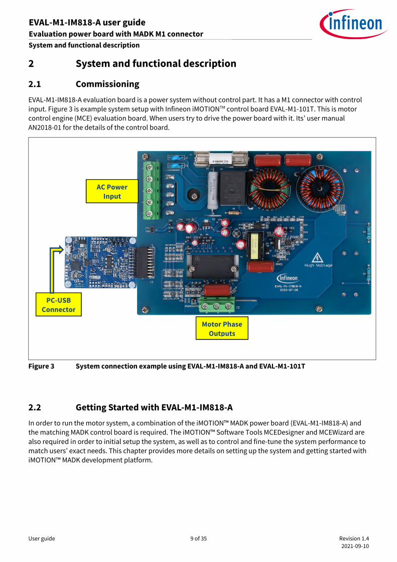
EVAL-M1-IM818-A evaluation board is a power system without control part. It has a M1 connector with control
input. Figure 3 is example system setup with Infineon iMOTIONTM control board EVAL-M1-101T. This is motor
control engine (MCE) evaluation board. When users try to drive the power board with it. Its’ user manual
AN2018-01 for the details of the control board.
Figure 3 System connection example using EVAL-M1-IM818-A and EVAL-M1-101T
2.2 Getting Started with EVAL-M1-IM818-A
In order to run the motor system, a combination of the iMOTION™ MADK power board (EVAL-M1-IM818-A) and
the matching MADK control board is required. The iMOTION™ Software Tools MCEDesigner and MCEWizard are
also required in order to initial setup the system, as well as to control and fine-tune the system performance to
match users’ exact needs. This chapter provides more details on setting up the system and getting started with
iMOTION™ MADK development platform.
PC-USB
Connector
AC Power
Input
Motor Phase
Outputs

User guide 10 of 35 Revision 1.4
2021-09-10
EVAL-M1-IM818-A user guide Evaluation power board with MADK M1 connector
System and functional description
2.3 Setting up the system
After downloading and installing the iMOTION™ PC Tools (MCEWizard and MCEDesigner), the following steps
needs to be executed in order to run the motor. Refer to user manual for iMOTION™ MADK control board such
as (EVAL-M1-101T), MCEWizard and MCEDesigner documentation for more information.
Figure 3 shows the system connection using EVAL-M1-IM818-A and control board (used control board EVAL-M1-
101T for example).
Setting step:
1. Connect PC-USB connector on the on-board-debugger to the PC via USB cable.
2. Connect EVAL-M1-IM818-A’s MADK M1 20-pin interface connector (J3) to control board (see figure 3).
3. Get the latest “IMC101T-T038 MCE Software Package” available on www.infineon.com/imotion-software
web page. (Infineon iMOTION™ control IC IMC101T-T038 is used for control board EVAL-M1-101T).
4. Connect motor phase outputs to the motor.
5. Use MCEWizard to enter the motor and evaluation board hardware parameters and click button “Export to
Designer file (.txt)” to system drive parameters file which will be used by MCEDesigner.
6. Connect AC power to power input connector (J1) and power on system.
7. Open MCEDesigner and open MCEDesigner default configuration file (.irc) for IMC101T devices
(IMC101T_xx.irc) by clicking “File” menu and select “Open” in the pull-down list.
8. Import system drive parameters file (generated in step 5) into MCEDesigner by clicking “File” > “Import Drive
Parameters”. Select “Update All” radio button.
9. Program the MCE Firmware and system parameters into the internal Flash memory of iMOTION™ IC by
clicking “Tools > Programmer “in the pull-down menu, and then clicking on the “Program Firmware and
Parameter” radio button. See chapter MCEDesigner setup overview section 2.4 for more details. If the latest
version of MCE firmware is already programmed into the IMC101T-T038 IC, then programming firmware can
be skipped by selecting “Program Parameters” radio button option. Finally click “Start” button to program
firmware and parameter (or parameters only when programming firmware was skipped).
10. Start the motor by clicking the green traffic light button in the control bar.
2.4 iMOTIOMTM development tools and software
The iMOTION™Development Tool installers for MCEDesigner and MCEWizard are available for download via
Infineon iMOTIONTM website (http://www.infineon.com/imotion-software). All the available tools and software
variants are listed there.
On-board debugger uses the SEGGER J-Link’s driver for UART communication with IMC101T-T038. J-Link driver
will be installed during the MCEDesigner installation. In case the driver is not installed properly, please go to
SEGGER J-Link website to download and install the latest J-Link “Software and Documentation pack for
Windows”.
User guide 11 of 35 Revision 1.4
2021-09-10
EVAL-M1-IM818-A user guide Evaluation power board with MADK M1 connector
System and functional description
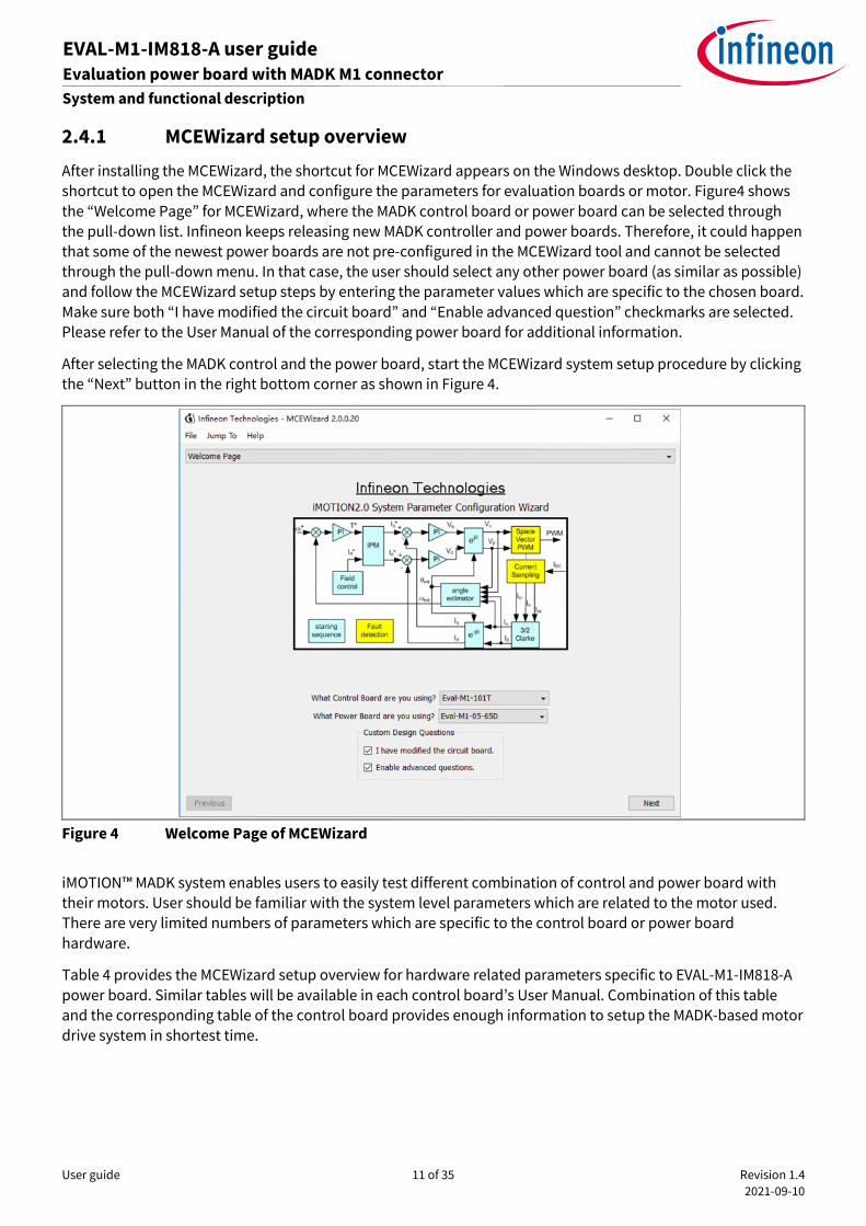
2.4.1 MCEWizard setup overview
After installing the MCEWizard, the shortcut for MCEWizard appears on the Windows desktop. Double click the
shortcut to open the MCEWizard and configure the parameters for evaluation boards or motor. Figure4 shows
the “Welcome Page” for MCEWizard, where the MADK control board or power board can be selected through
the pull-down list. Infineon keeps releasing new MADK controller and power boards. Therefore, it could happen
that some of the newest power boards are not pre-configured in the MCEWizard tool and cannot be selected
through the pull-down menu. In that case, the user should select any other power board (as similar as possible)
and follow the MCEWizard setup steps by entering the parameter values which are specific to the chosen board.
Make sure both “I have modified the circuit board” and “Enable advanced question” checkmarks are selected.
Please refer to the User Manual of the corresponding power board for additional information.
After selecting the MADK control and the power board, start the MCEWizard system setup procedure by clicking
the “Next” button in the right bottom corner as shown in Figure 4.
Figure 4 Welcome Page of MCEWizard
iMOTION™ MADK system enables users to easily test different combination of control and power board with
their motors. User should be familiar with the system level parameters which are related to the motor used.
There are very limited numbers of parameters which are specific to the control board or power board
hardware.
Table 4 provides the MCEWizard setup overview for hardware related parameters specific to EVAL-M1-IM818-A
power board. Similar tables will be available in each control board’s User Manual. Combination of this table
and the corresponding table of the control board provides enough information to setup the MADK-based motor
drive system in shortest time.
User guide 12 of 35 Revision 1.4
2021-09-10
EVAL-M1-IM818-A user guide Evaluation power board with MADK M1 connector
System and functional description
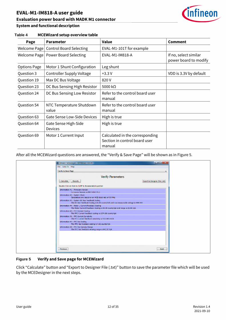
Table 4 MCEWizard setup overview table
Page Parameter Value Comment
Welcome Page Control Board Selecting EVAL-M1-101T for example
Welcome Page Power Board Selecting EVAL-M1-IM818-A If no, select similar
power board to modify
Options Page Motor 1 Shunt Configuration Leg shunt
Question 3 Controller Supply Voltage +3.3 V VDD is 3.3V by default
Question 19 Max DC Bus Voltage 820 V
Question 23 DC Bus Sensing High Resistor 5000 kΩ
Question 24 DC Bus Sensing Low Resistor Refer to the control board user
manual
Question 54 NTC Temperature Shutdown
value
Refer to the control board user
manual
Question 63 Gate Sense Low-Side Devices High is true
Question 64 Gate Sense High-Side
Devices
High is true
Question 69 Motor 1 Current Input Calculated in the corresponding
Section in control board user
manual
After all the MCEWizard questions are answered, the “Verify & Save Page” will be shown as in Figure 5.
Figure 5 Verify and Save page for MCEWizard
Click “Calculate” button and “Export to Designer File (.txt)” button to save the parameter file which will be used
by the MCEDesigner in the next steps.
User guide 13 of 35 Revision 1.4
2021-09-10
EVAL-M1-IM818-A user guide Evaluation power board with MADK M1 connector
System and functional description
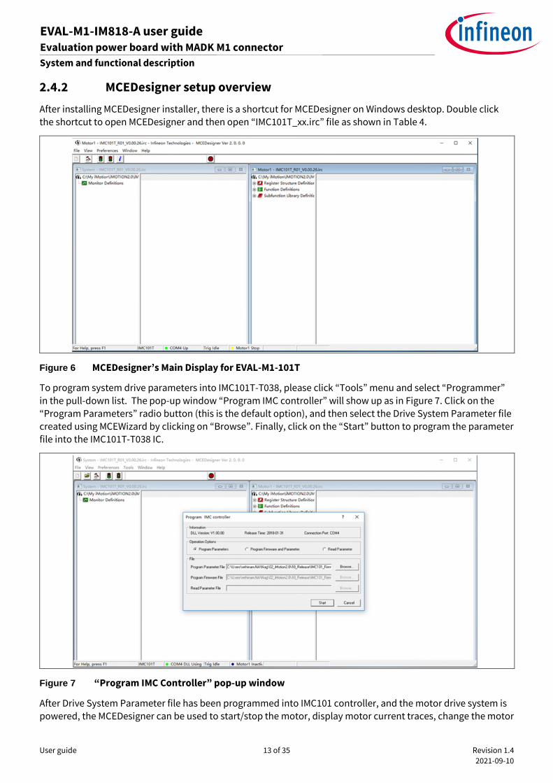
2.4.2 MCEDesigner setup overview
After installing MCEDesigner installer, there is a shortcut for MCEDesigner on Windows desktop. Double click
the shortcut to open MCEDesigner and then open “IMC101T_xx.irc” file as shown in Table 4.
Figure 6 MCEDesigner’s Main Display for EVAL-M1-101T
To program system drive parameters into IMC101T-T038, please click “Tools” menu and select “Programmer”
in the pull-down list. The pop-up window “Program IMC controller” will show up as in Figure 7. Click on the
“Program Parameters” radio button (this is the default option), and then select the Drive System Parameter file
created using MCEWizard by clicking on “Browse”. Finally, click on the “Start” button to program the parameter
file into the IMC101T-T038 IC.
Figure 7 “Program IMC Controller” pop-up window
After Drive System Parameter file has been programmed into IMC101 controller, and the motor drive system is
powered, the MCEDesigner can be used to start/stop the motor, display motor current traces, change the motor

User guide 14 of 35 Revision 1.4
2021-09-10
EVAL-M1-IM818-A user guide Evaluation power board with MADK M1 connector
System and functional description
speeds, modify drive parameters and many other functions. Please refer to the MCEDesigner documentation
for more details.
Note: On-board Debugger portion of EVAL-M1-101T is galvanically isolated from the controller portion and the
attached power board. In order to program the parameters or firmware to the IMC101T-T038 controller, the
3.3 V DC voltage needs to be supplied to the controller portion of the EVAL-M1-101T. This voltage can either
be supplied by the power board (MADK power boards are designed to supply the 3.3 V to the control board
through M1 connector) or by feeding the 3.3 V DC voltage to the control board through some of the available
3.3 V access/test points if the power board is not attached to the EVAL-M1-101T control board.
To program new firmware and Drive System Parameter into IMC101T-T038, please click “Tools” menu and
select “Programmer” in the pull-down list. The pop-up window “Program IMC controller” will show up as in
Figure 8. Click on the “Program Firmware and Parameter” radio button, and select the Drive System Parameter
file created using MCEWizard by clicking on the “Browse” button on the row of “Program Parameter File”, and
then select the firmware file by clicking on the “Browse” button on the row of “Program Firmware File”. Finally,
click on the “Start” button to program the parameter file into the IMC101T-T038 IC.
Figure 8 Program Firmware and Parameter in “Program IMC Controller” pop-up window
All the latest firmware files for different types of iMOTIONTM motor control ICs are available for download via
Infineon iMOTIONTM website (http://www.infineon.com/imotion-software).
2.5 Description of the functional blocks
This chapter covers the hardware design of the EVAL-M1-IM818-A in more detail. It’s includes the functional
groups of this power board and interface definition. Engineers can use this board to evaluate the performance
easily. And it is also helpful for users to develop their solution based on the evaluation board design.
User guide 15 of 35 Revision 1.4
2021-09-10
EVAL-M1-IM818-A user guide Evaluation power board with MADK M1 connector
System and functional description
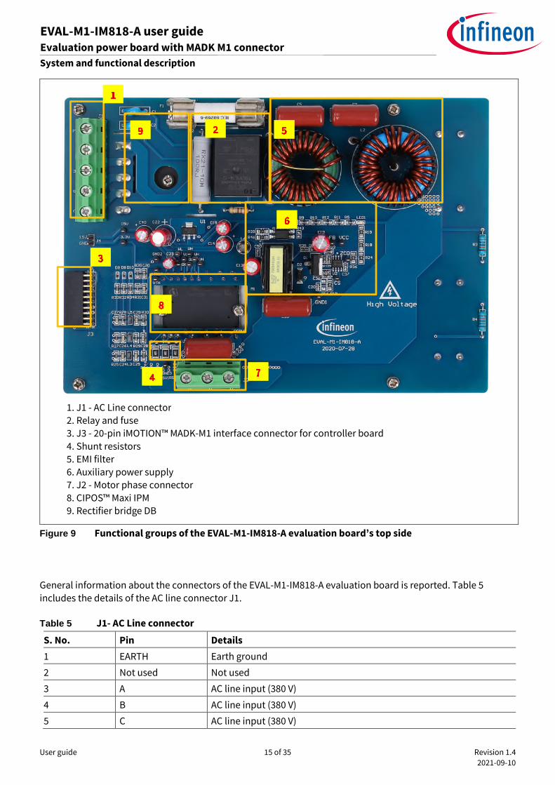
Figure 9 Functional groups of the EVAL-M1-IM818-A evaluation board’s top side
General information about the connectors of the EVAL-M1-IM818-A evaluation board is reported. Table 5
includes the details of the AC line connector J1.
Table 5 J1- AC Line connector
S. No. Pin Details
1 EARTH Earth ground
2 Not used Not used
3 A AC line input (380 V)
4 B AC line input (380 V)
5 C AC line input (380 V)
1. J1 - AC Line connector
2. Relay and fuse
3. J3 - 20-pin iMOTION™ MADK-M1 interface connector for controller board
4. Shunt resistors
5. EMI filter
6. Auxiliary power supply
7. J2 - Motor phase connector
8. CIPOS™ Maxi IPM
9. Rectifier bridge DB

User guide 16 of 35 Revision 1.4
2021-09-10
EVAL-M1-IM818-A user guide Evaluation power board with MADK M1 connector
System and functional description
Table 6 provides the pin assignments of the 20-pin iMOTION™MADK-M1 interface connector J3. This connector
is the interface to the controller board.
Table 6 J2 - iMOTION™MADK-M1 20-pin interface connector for controller board
Pin Name Pin Name Connectors
1 PWMUH 3.3 V compatible logic input for high side gate driver-Phase U
2 GND Ground
3 PWMUL 3.3 V compatible logic input for low side gate driver-Phase U
4 GND Ground
5 PWMVH 3.3 V compatible logic input for high side gate driver-Phase V
6 +3.3V On board 3.3 V supply
7 PWMVL 3.3 V compatible logic input for low side gate driver-Phase V
8 +3.3V On board 3.3 V supply
9 PWMWH 3.3 V compatible logic input for high side gate driver-Phase W
10 I_U Shunt voltage phase U
11 PWMWL 3.3 V compatible logic input for low side gate driver-Phase W
12 I_U- Ground
13 GK Gate kill signal – active low when overcurrent is detected
14 DCBSENSE DC bus positive voltage, scaled in 0-3.3 V range by a voltage divider
15 VTH Thermistor Output
16 I_V Shunt voltage phase V
17 I_V- Ground
18 I_W Shunt voltage phase W
19 I_W- Ground
20 VCC 15 V Power Supply
Table 7 denotes the details of the motor side connector J2.
Table 7 J2- Motor side connector
S. No. Pin Details
1 W Connected to motor phase U
2 V Connected to motor phase V
3 U Connected to motor phase W
2.6 Hardware description of EVAL-M1-IM818-A
To meet individual customer requirements and make the EVAL-M1-IM818-A evaluation board a basis for
development or modification, all necessary technical data like schematics, layout and components are
included in this chapter.
User guide 17 of 35 Revision 1.4
2021-09-10
EVAL-M1-IM818-A user guide Evaluation power board with MADK M1 connector
System and functional description
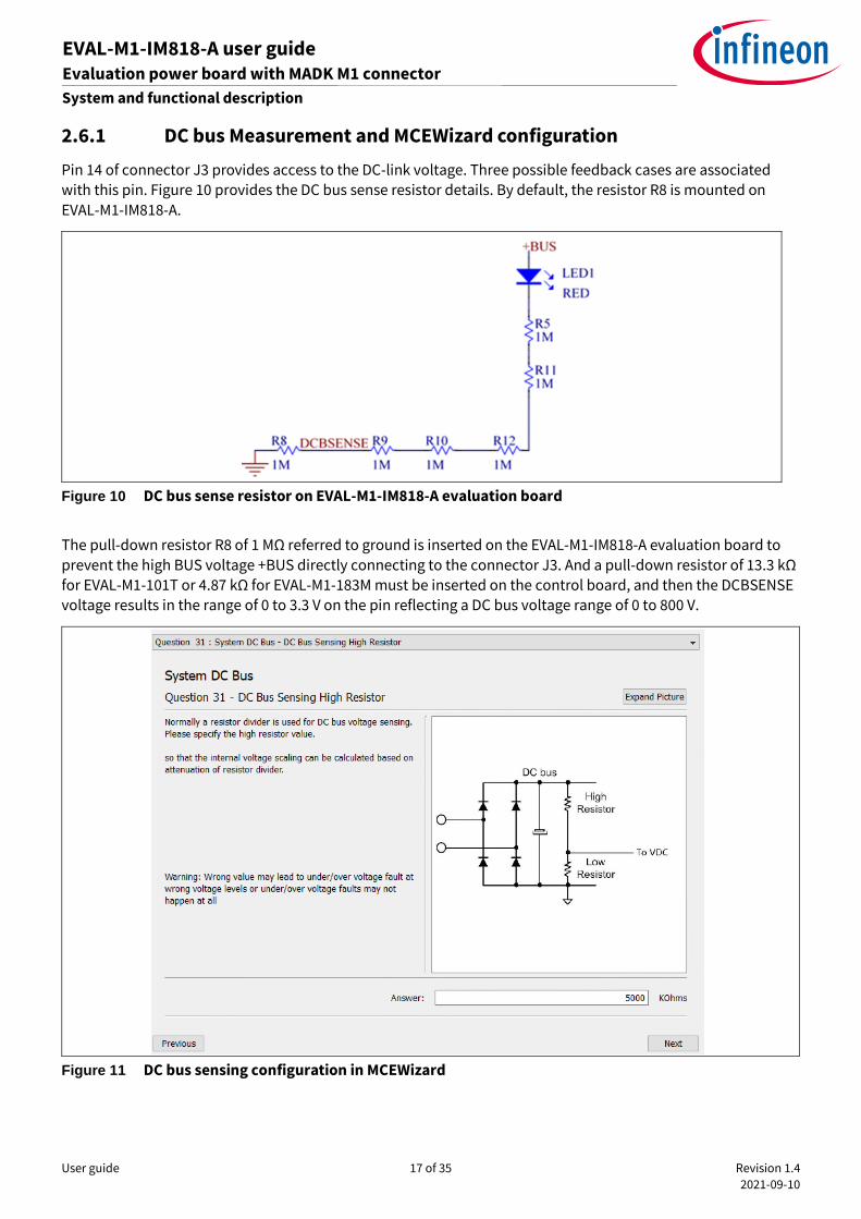
2.6.1 DC bus Measurement and MCEWizard configuration
Pin 14 of connector J3 provides access to the DC-link voltage. Three possible feedback cases are associated
with this pin. Figure 10 provides the DC bus sense resistor details. By default, the resistor R8 is mounted on
EVAL-M1-IM818-A.
Figure 10 DC bus sense resistor on EVAL-M1-IM818-A evaluation board
The pull-down resistor R8 of 1 MΩ referred to ground is inserted on the EVAL-M1-IM818-A evaluation board to
prevent the high BUS voltage +BUS directly connecting to the connector J3. And a pull-down resistor of 13.3 kΩ
for EVAL-M1-101T or 4.87 kΩ for EVAL-M1-183M must be inserted on the control board, and then the DCBSENSE
voltage results in the range of 0 to 3.3 V on the pin reflecting a DC bus voltage range of 0 to 800 V.
Figure 11 DC bus sensing configuration in MCEWizard

User guide 18 of 35 Revision 1.4
2021-09-10
EVAL-M1-IM818-A user guide Evaluation power board with MADK M1 connector
System and functional description
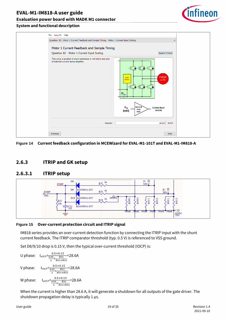
2.6.2 Motor External Current feedback configuration and calculation
The current input value is product of the shunt resistance in milliohms and gain of External current sense
amplifier for EVAL-M1-101T as shown in Figure 12.
Figure 12 Current shunt feedback and sample timing for EVAL-M1-101T
The external amplifier gain circuit can be found in the schematics or user manual for the control board (For
example, EVAL-M1-101T see Figure 13).
Figure 13 depicts IU+ current feedback sensing circuity on EVAL-M1-101T evaluation board. Please note that the
default external amplification gain is less than 1 for current sense in this evaluation board.
Figure 13 The part of Current feedback on the EVAL-M1-101T evaluation board
Based on the principle of Kirchhoff's voltage law,
𝑉2 ≈ 𝑉1 ≈ (𝑉𝐷𝐷 − 𝐼𝑠ℎ ∗ 𝑅𝑠ℎ) ∗𝑅7
𝑅6 + 𝑅7+ 𝐼𝑠ℎ ∗ 𝑅𝑠ℎ =
𝑅7𝑅6 + 𝑅7
𝑉𝐷𝐷 +𝑅6
𝑅6 + 𝑅7𝑅𝑠ℎ ∗ 𝐼𝑠ℎ
𝐶𝑢𝑟𝑟𝑒𝑛𝑡 𝑖𝑛𝑝𝑢𝑡 =𝑅6
𝑅6 + 𝑅7𝑅𝑠ℎ =
5
6𝑅𝑠ℎ
Based on this calculation, the current input for the MADK combination of EVAL-M1-101T and EVAL-M1-IM818-A
is 20.83 mV/A.
Please use same procedure to calculate the current input for other combinations of MADK boards and enter it
into MCEWizard as shown in Figure 14
R7 2k, 1% C15220pF
IU+
R610k, 1%
+3.3V
R8 100RRsh
iMOTION
IU
Controller
V1 V2 6
Current Shunt
Resistor on power board
1sh
User guide 19 of 35 Revision 1.4
2021-09-10
EVAL-M1-IM818-A user guide Evaluation power board with MADK M1 connector
System and functional description
Figure 14 Current feedback configuration in MCEWizard for EVAL-M1-101T and EVAL-M1-IM818-A
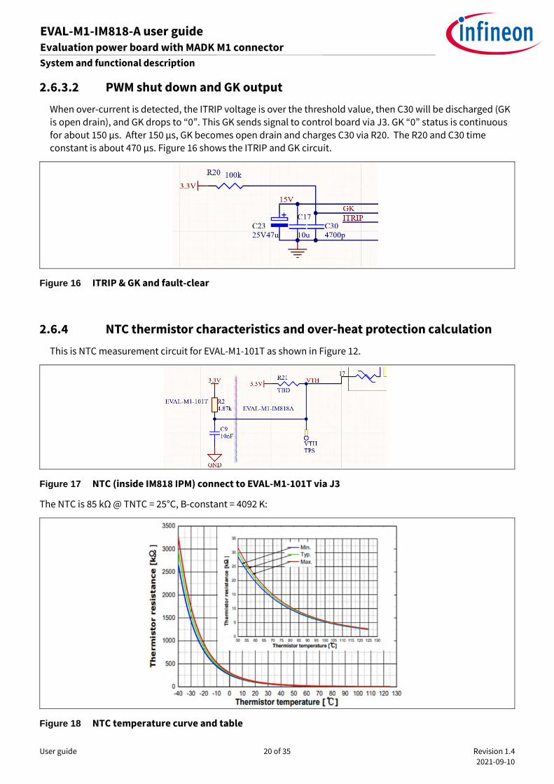
2.6.3 ITRIP and GK setup
2.6.3.1 ITRIP setup
Figure 15 Over-current protection circuit and ITRIP signal
IM818 series provides an over-current detection function by connecting the ITRIP input with the shunt
current feedback. The ITRIP comparator threshold (typ. 0.5 V) is referenced to VSS ground.
Set D8/9/10 drop is 0.15 V, then the typical over-current threshold (IOCP) is:
U phase: IuOCP=0.5+0.15
0.05
2×
𝑅31
𝑅31+𝑅33
=28.6A
V phase: IVOCP=0.5+0.15
0.05
2×
𝑅31
𝑅31+𝑅32
=28.6A
W phase: IwOCP=0.5+0.15
0.05
2×
𝑅31
𝑅31+𝑅34
=28.6A
When the current is higher than 28.6 A, it will generate a shutdown for all outputs of the gate driver. The
shutdown propagation delay is typically 1 µs.
User guide 20 of 35 Revision 1.4
2021-09-10
EVAL-M1-IM818-A user guide Evaluation power board with MADK M1 connector
System and functional description
2.6.3.2 PWM shut down and GK output
When over-current is detected, the ITRIP voltage is over the threshold value, then C30 will be discharged (GK
is open drain), and GK drops to “0”. This GK sends signal to control board via J3. GK “0” status is continuous
for about 150 µs. After 150 µs, GK becomes open drain and charges C30 via R20. The R20 and C30 time
constant is about 470 µs. Figure 16 shows the ITRIP and GK circuit.
Figure 16 ITRIP & GK and fault-clear
2.6.4 NTC thermistor characteristics and over-heat protection calculation
This is NTC measurement circuit for EVAL-M1-101T as shown in Figure 12.
Figure 17 NTC (inside IM818 IPM) connect to EVAL-M1-101T via J3
The NTC is 85 kΩ @ TNTC = 25°C, B-constant = 4092 K:
Figure 18 NTC temperature curve and table
User guide 21 of 35 Revision 1.4
2021-09-10
EVAL-M1-IM818-A user guide Evaluation power board with MADK M1 connector
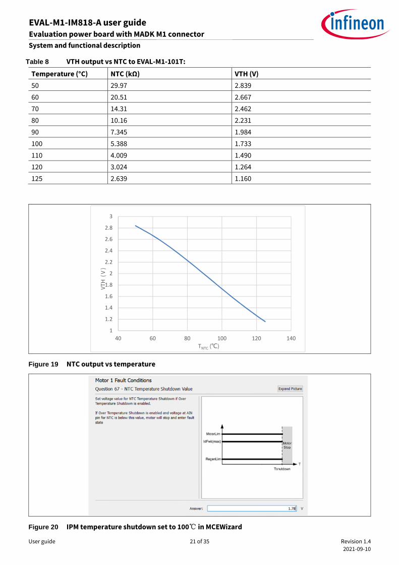
System and functional description
Table 8 VTH output vs NTC to EVAL-M1-101T:
Temperature (°C) NTC (kΩ) VTH (V)
50 29.97 2.839
60 20.51 2.667
70 14.31 2.462
80 10.16 2.231
90 7.345 1.984
100 5.388 1.733
110 4.009 1.490
120 3.024 1.264
125 2.639 1.160
Figure 19 NTC output vs temperature
Figure 20 IPM temperature shutdown set to 100 in MCEWizard
1
1.2
1.4
1.6
1.8
2
2.2
2.4
2.6
2.8
3
40 60 80 100 120 140
VT
H( V
)
TNTC ()
User guide 22 of 35 Revision 1.4
2021-09-10
EVAL-M1-IM818-A user guide Evaluation power board with MADK M1 connector
System and functional description
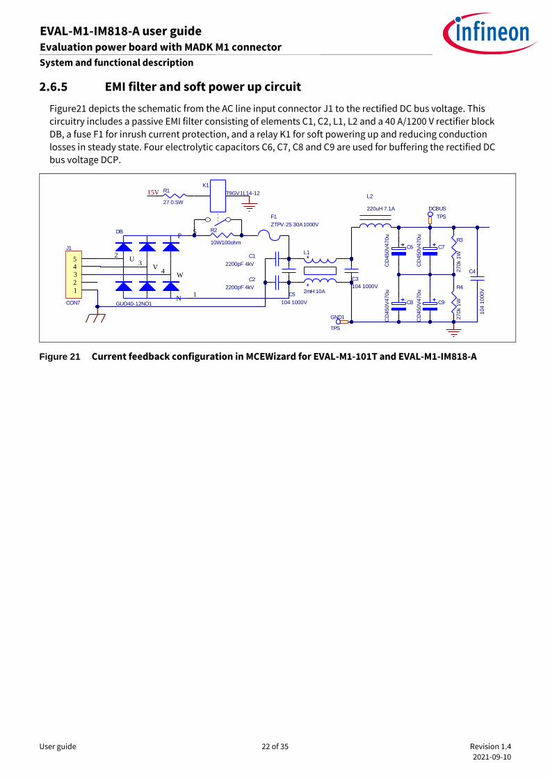
2.6.5 EMI filter and soft power up circuit
Figure21 depicts the schematic from the AC line input connector J1 to the rectified DC bus voltage. This
circuitry includes a passive EMI filter consisting of elements C1, C2, L1, L2 and a 40 A/1200 V rectifier block
DB, a fuse F1 for inrush current protection, and a relay K1 for soft powering up and reducing conduction
losses in steady state. Four electrolytic capacitors C6, C7, C8 and C9 are used for buffering the rectified DC
bus voltage DCP.
Figure 21 Current feedback configuration in MCEWizard for EVAL-M1-101T and EVAL-M1-IM818-A
U2
V3
W4
P5
N1
DB
GUO40-12NO1
R2
10W100ohm
K1
T9GV1L14-12
R3
270k
1W
R4
270k
1W
C6
CD
450V
470u
C8
CD
450V
470u
L2
220uH 7.1A
C4
104
1000V1
2345
J1
CON7
R1
27 0.5W
15V
C5
104 1000V
C3
104 1000V**
L1
2mH 10A
F1
ZTPV-25 30A1000V
C1
2200pF 4kV
C2
2200pF 4kV
C7
CD
450V
470u
C9
CD
450V
470u
DCBUS
TPS
GND1
TPS
User guide 23 of 35 Revision 1.4
2021-09-10
EVAL-M1-IM818-A user guide Evaluation power board with MADK M1 connector
Schematic for EMI filter and AC/DC section of the EVAL-M1-IM818-A evaluation board
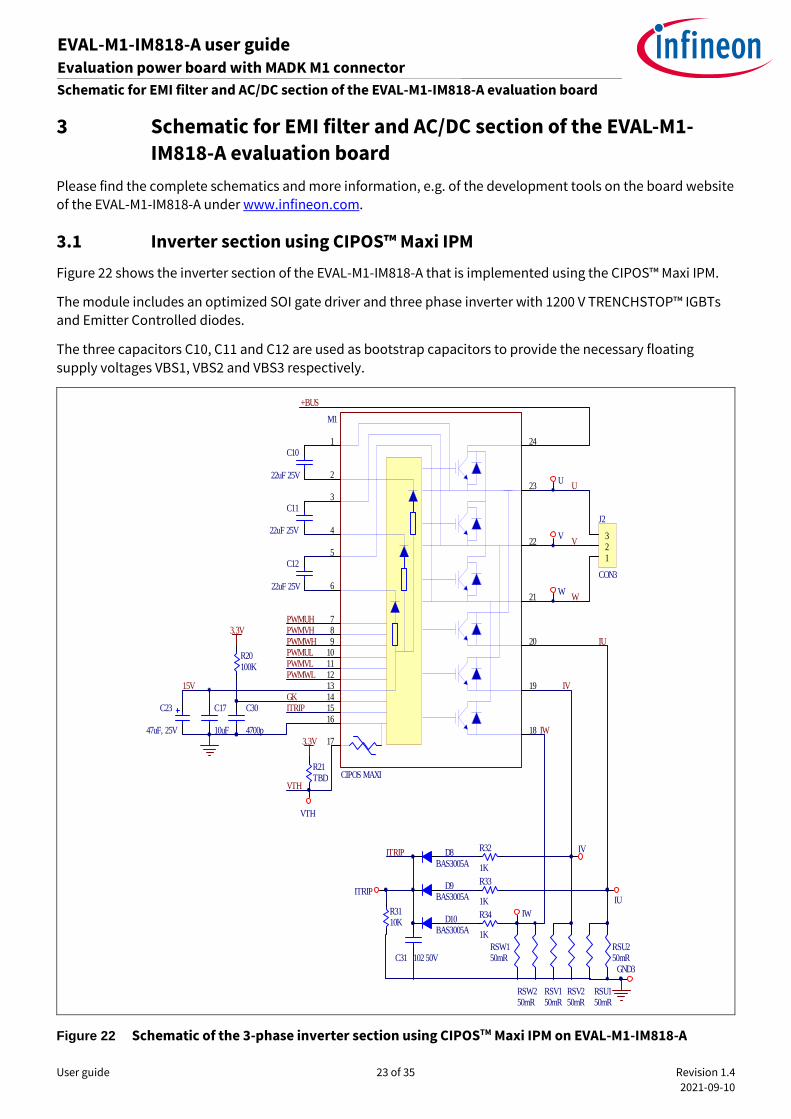
3 Schematic for EMI filter and AC/DC section of the EVAL-M1-
IM818-A evaluation board
Please find the complete schematics and more information, e.g. of the development tools on the board website
of the EVAL-M1-IM818-A under www.infineon.com.
3.1 Inverter section using CIPOS™ Maxi IPM
Figure 22 shows the inverter section of the EVAL-M1-IM818-A that is implemented using the CIPOS™ Maxi IPM.
The module includes an optimized SOI gate driver and three phase inverter with 1200 V TRENCHSTOP™ IGBTs
and Emitter Controlled diodes.
The three capacitors C10, C11 and C12 are used as bootstrap capacitors to provide the necessary floating
supply voltages VBS1, VBS2 and VBS3 respectively.
Figure 22 Schematic of the 3-phase inverter section using CIPOSTM Maxi IPM on EVAL-M1-IM818-A
RSW150mR
RSW250mR
U
V
W
123
J2
CON3
C17
10uF
C10
22uF 25V
C11
22uF 25V
C12
22uF 25V
PWMUHPWMVHPWMWHPWMULPWMVLPWMWL
15V
C31 102 50V
VTH
ITRIP
C30
4700p
GK
RSV150mR
RSV250mR
RSU150mR
RSU250mR
IU
IV
IW
+BUS
ITRIP
3.3V
R33
1K
R32
1K
R34
1K
R3110K
C23
47uF, 25V
R21TBD
R20100K
3.3V
1
2
3
24
23
22
21
20
19
1817
16
121110987
131415
6
5
4
M1
CIPOS MAXI
U
V
W
IV
IU
IW
GND3
ITRIP
VTH
D8BAS3005A
D9BAS3005A
D10BAS3005A

User guide 24 of 35 Revision 1.4
2021-09-10
EVAL-M1-IM818-A user guide Evaluation power board with MADK M1 connector
Schematic for EMI filter and AC/DC section of the EVAL-M1-IM818-A evaluation board
3.2 Auxiliary power supply
Figure 23 depicts the schematic of the auxiliary power supply of the EVAL-M1-IM818-A board. The circuit
includes the ICE5QSAG that is used to generate 15 V directly from the DC bus. VCC is connected to the gate
drivers inside the CIPOS™ IPM.
Figure 23 Schematic of the 3-phase inverter section using CIPOSTM Maxi IPM on EVAL-M1-IM818-A
The linear voltage regulator IFX25001ME V33 generates 3.3 V from a 15 V power supply VCC. Both VCC and 3.3 V
are also present on the 20-pin interface connector J2 to power circuitry on the controller board.
Q1
STP3N150
C2216V470u
15V 0.5A
C35
104
1000V
15V
TPS1 10
3 94
5
7
6
*
*
*
*
TR1
WE-750344164
D12
US1D
D13
BAV20W
R48
0R
R47
27R
R13
27R
ZD
1
22V
ZD
2
3.6
V
12
34
8
7
6 5
*G
ND
VC
CSO
UR
CE
GA
TE
FB
VIN
CS
ZC
D
U2ICE5QSAG
D21
MBR2150
C13
470µF
/25V
C14
100µF
/25V
D3
B1100
C18
120µF
/16V
C19
47µF
/35V
R35
30K
R14
3M
R
R17
3M
R
R23
3M
R
R15
20M
R
R18
20M
R
R24
20M
R
R36
20M
R
R37
62K
R
R42
62K
R
R19
4R3
C20
33nF/50V
R16
NF
C36
47nF
/50V
C37
120pF
/50V
C38
3.3
nF
/50V
C39
100nF
/50V
1
2
3
C
A
R
U3
TL431BSM
34
12
U4IC-817SM
R43N
F
R46
1.2KR
R39
1.2
KR R38
49.9KR
C33 1nF/50V
C34
330nF
/50V
R44
10K
RR
45
649K
R
R40
NF R
41
49.9
KR
C21
2.2nF/1kV
C32
2.2nF/1kV
6V
R22
10R
15V
GND
GND
D2
US1M
R6
200KR
R7
200KR
C15
2.2nF/1kV
C16
2.2nF/1kV
D1
US1M
+BUS
GND2
TPS
VCC
TPS
CS
TPS
VCCZCD
TPSFB
TPS
C50 100nF/50V
C40
100µF
/25V
L6
2.2µH
I1
Q3
GN
D2,
4
U1
IFX25001ME V333.3V

User guide 25 of 35 Revision 1.4
2021-09-10
EVAL-M1-IM818-A user guide Evaluation power board with MADK M1 connector
Schematic for EMI filter and AC/DC section of the EVAL-M1-IM818-A evaluation board
3.3 Layout
The layout of this board can be used for different voltage or power classes. The PCB has two electrical layers
with 35 µm copper by default and its size is 197 mm × 140 mm. The PCB board thickness is 1.6 mm. Get in
contact with our technical support team to get more detailed information and the latest Gerber-files.
Figure 24 illustrates the top assembly print of the evaluation board.
Figure 24 Top assembly print of the EVAL-M1-IM818-A evaluation board
Figure 25 depicts the bottom assembly print of the evaluation board.
Figure 25 Bottom assembly print of the EVAL-M1-IM818-A evaluation board
User guide 26 of 35 Revision 1.4
2021-09-10
EVAL-M1-IM818-A user guide Evaluation power board with MADK M1 connector
Schematic for EMI filter and AC/DC section of the EVAL-M1-IM818-A evaluation board
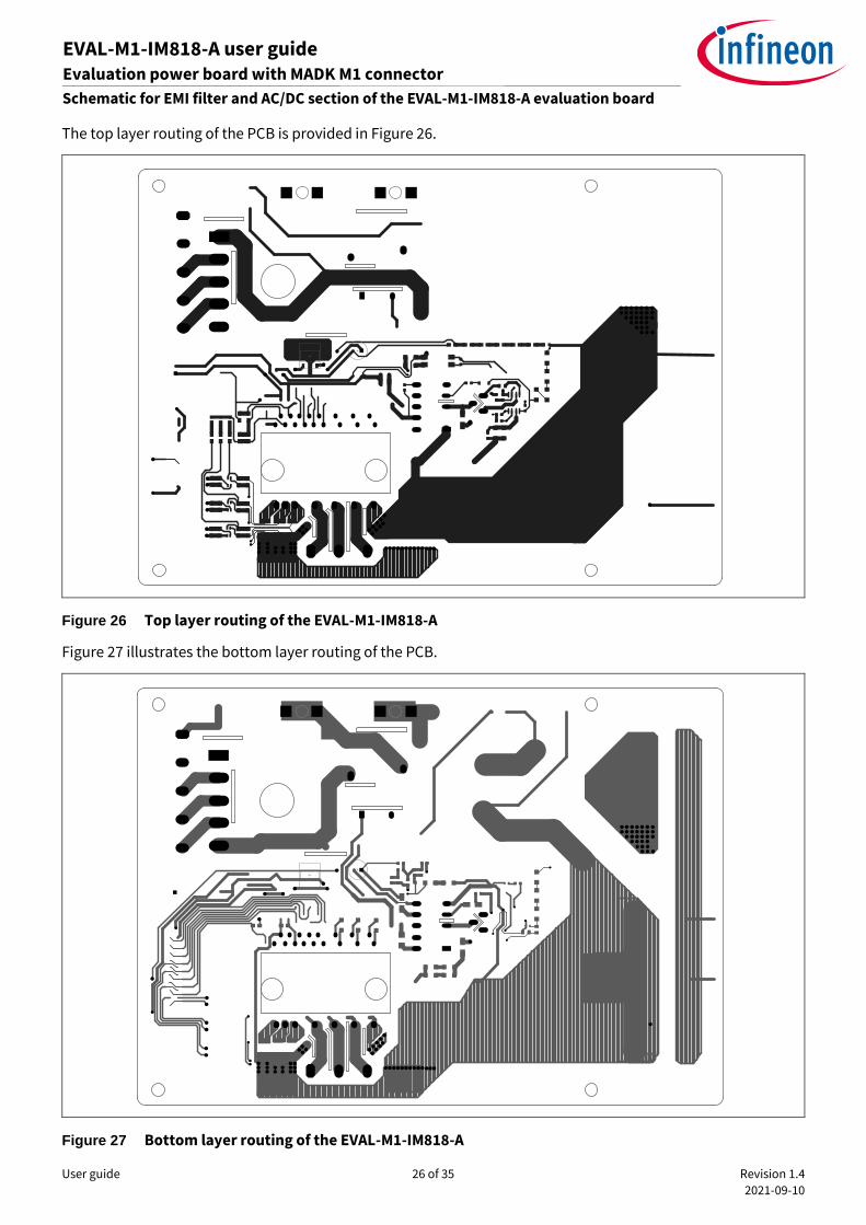
The top layer routing of the PCB is provided in Figure 26.
Figure 26 Top layer routing of the EVAL-M1-IM818-A
Figure 27 illustrates the bottom layer routing of the PCB.
Figure 27 Bottom layer routing of the EVAL-M1-IM818-A

User guide 27 of 35 Revision 1.4
2021-09-10
EVAL-M1-IM818-A user guide Evaluation power board with MADK M1 connector
Schematic for EMI filter and AC/DC section of the EVAL-M1-IM818-A evaluation board
3.4 Bill of material
The complete bill of material is available on the download section of the Infineon homepage. A log-in is
required to download this material.
Table 9 provides the complete bill of materials of the evaluation board.
Table 9 BOM of the most important parts of the EVAL-M1-IM818-A
No. Designato
r
Part description Part number Manufacturer
1 C6, C7, C8,
C9
CD470UF 450V 861221486023 Wurth Electronics Inc.
2 C13 470uF 25V 860020474014 Wurth Electronics Inc.
3 C14, C40 100uF 25V 865090449009 Wurth Electronics Inc.
4 C18 120uF 16V 860010373007 Wurth Electronics Inc.
5 C19 47uF 35V 860010572005 Wurth Electronics Inc.
6 C22 470uF 16V 870025374007 Wurth Electronics Inc.
7 C23 47uF 25V 860080472002 Wurth Electronics Inc.
8 TR1 Transformer 750344164 Wurth Electronics Inc.
9 J1
CONN TERM BLOCK 5POS
9.52MM PCB
691250910003
691250910002
Wurth Electronics Inc.
10 J2
CONN TERM BLOCK 3POS
9.52MM PCB
691250910003 Wurth Electronics Inc.
11 J3
CONN RCPT .100" 20PS DL R/A
GOLD
613020243121 Wurth Electronics Inc.
12 J4 CONN HEADER 2 POS 2.54 61300211121 Wurth Electronics Inc.
13 L2 220uH 7.1A PI200385V1 POCO Holding Co.,LTD
14 L3, L4, L5
WE-CNSW SMD Common Mode
Line Filter
744232101 Wurth Electronics Inc.
15 U1 IFX25001ME V33 IFX25001MEV33HTSA1 Infineon Technologies
16 D8, D9,
D10
BAS3005A-02V BAS3005A02VH6327XTSA1 Infineon Technologies
17 U2 ICE5QSAG ICE5QSAGXUMA1 Infineon Technologies
18 M1 IM818-MCC IM818MCCXKMA1 Infineon Technologies

User guide 28 of 35 Revision 1.4
2021-09-10
EVAL-M1-IM818-A user guide Evaluation power board with MADK M1 connector
System performance
4 System performance
The evaluation board EVAL-M1-IM818-A is general power demonstration platform with CIPOS™ Maxi IPM IM818
series. And focus on 380 VAC input, and 1~4.8 kW output application. All test date is basic on the board with
different IPM. For end user, it is only default for IM818-MCC. Other IPMs can be directly compatible and replaced
(Warning). But don’t guarantee hardware change.
Warning:
EVAL-M1-IM818-A is only default for IM818-MCC, any hardware change will not be guaranteed.
All operations can be done only when the evaluation boards has been move away from the power for over
5 minutes and double check those all capacitance voltage are lower than 5V.
Operation only for those licensed professionals under qualified safety protection (including: person,
equipment, ESD).
For any re-install, it is necessary to clean the thermal conductive silicone grease and coating it again.
4.1 Test results for output ability
In order to test the total power capability of EVAL-M1-IM818-A, the IPM case temperature is tested with different
input and output currents.
The test temperature Ta = 25°C
Note: EVAL board provides air cooling option, and set 15 V 200 mA for fan drive.
Power setup:
400 VDC (298 VAC 50 Hz 3-phase input)
700 VDC (518 VAC 50 Hz 3-phase input)
380 VAC (3-phase input)
PWM frequency 6 kHz and 20 kHz three-phase modulation.
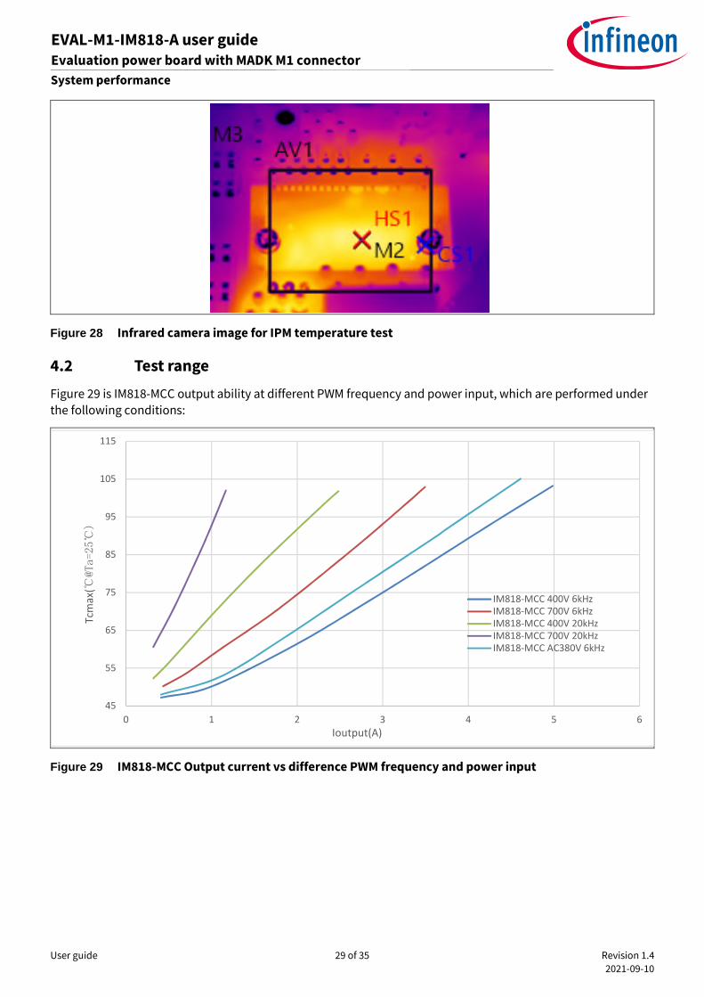
Figure 28 shows the IPM case temperature measured by an infrared camera. Run motor at 400 RPM and adjust
motor load until the hottest point in the center of IM818-MCC top of Tcmac=105°C (temperature rise reaches
80°C), get the curve for temperature rise by different setup.
User guide 29 of 35 Revision 1.4
2021-09-10
EVAL-M1-IM818-A user guide Evaluation power board with MADK M1 connector
System performance
Figure 28 Infrared camera image for IPM temperature test
4.2 Test range
Figure 29 is IM818-MCC output ability at different PWM frequency and power input, which are performed under
the following conditions:
Figure 29 IM818-MCC Output current vs difference PWM frequency and power input
45
55
65
75
85
95
105
115
0 1 2 3 4 5 6
Tcm
ax(
@Ta=25)
Ioutput(A)
IM818-MCC 400V 6kHzIM818-MCC 700V 6kHzIM818-MCC 400V 20kHzIM818-MCC 700V 20kHzIM818-MCC AC380V 6kHz
User guide 30 of 35 Revision 1.4
2021-09-10
EVAL-M1-IM818-A user guide Evaluation power board with MADK M1 connector
System performance
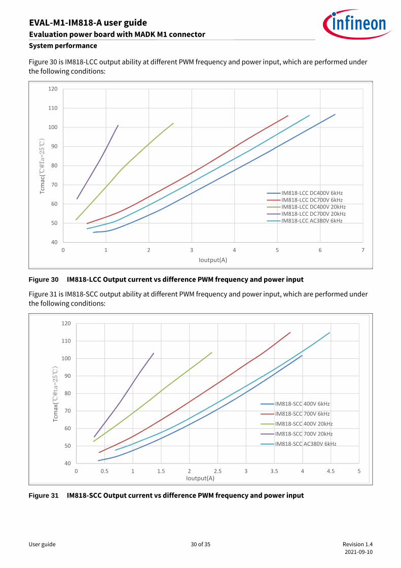
Figure 30 is IM818-LCC output ability at different PWM frequency and power input, which are performed under
the following conditions:
Figure 30 IM818-LCC Output current vs difference PWM frequency and power input
Figure 31 is IM818-SCC output ability at different PWM frequency and power input, which are performed under
the following conditions:
Figure 31 IM818-SCC Output current vs difference PWM frequency and power input
40
50
60
70
80
90
100
110
120
0 1 2 3 4 5 6 7
Tcm
ac(
@Ta=25
)
Ioutput(A)
IM818-LCC DC400V 6kHzIM818-LCC DC700V 6kHzIM818-LCC DC400V 20kHzIM818-LCC DC700V 20kHzIM818-LCC AC380V 6kHz
40
50
60
70
80
90
100
110
120
0 0.5 1 1.5 2 2.5 3 3.5 4 4.5 5
Tcm
ax(
@ta=25
)
Ioutput(A)
IM818-SCC 400V 6kHz
IM818-SCC 700V 6kHz
IM818-SCC 400V 20kHz
IM818-SCC 700V 20kHz
IM818-SCC AC380V 6kHz
User guide 31 of 35 Revision 1.4
2021-09-10
EVAL-M1-IM818-A user guide Evaluation power board with MADK M1 connector
System performance
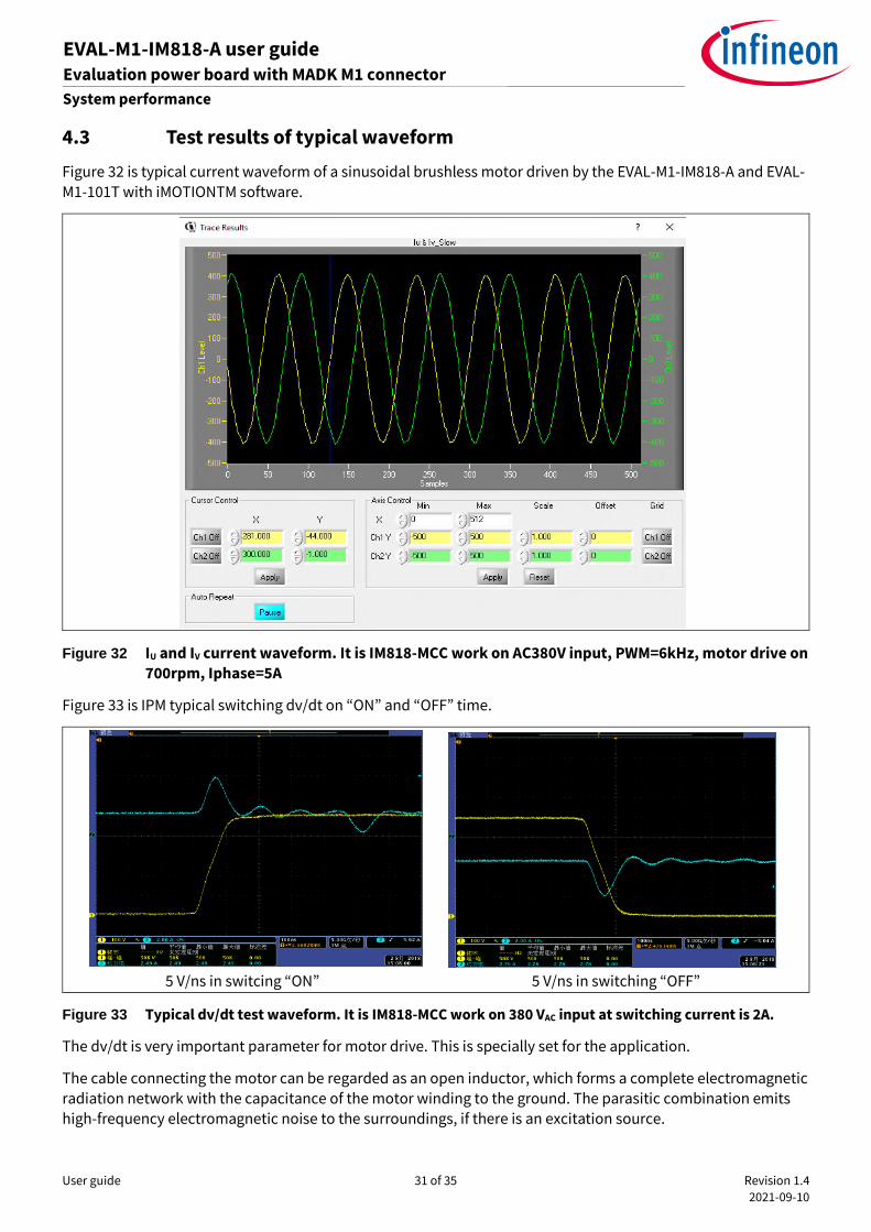
4.3 Test results of typical waveform
Figure 32 is typical current waveform of a sinusoidal brushless motor driven by the EVAL-M1-IM818-A and EVAL-
M1-101T with iMOTIONTM software.
Figure 32 IU and IV current waveform. It is IM818-MCC work on AC380V input, PWM=6kHz, motor drive on
700rpm, Iphase=5A
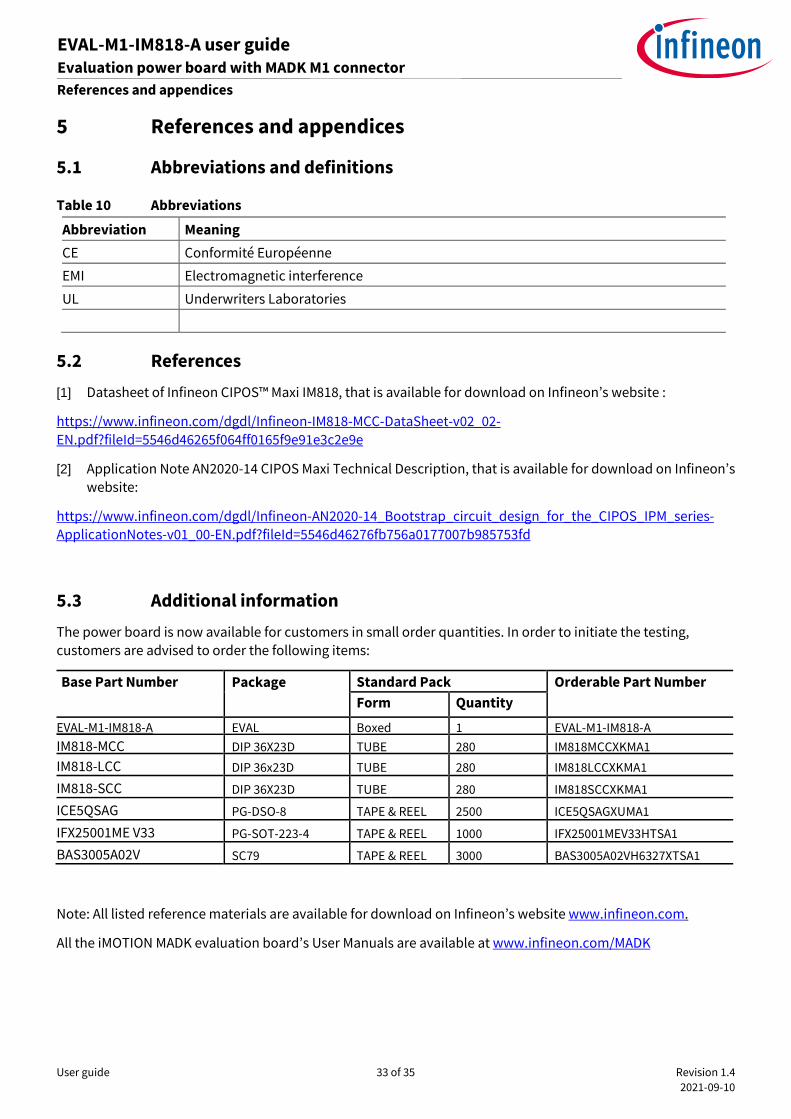
Figure 33 is IPM typical switching dv/dt on “ON” and “OFF” time.
5 V/ns in switcing “ON” 5 V/ns in switching “OFF”
Figure 33 Typical dv/dt test waveform. It is IM818-MCC work on 380 VAC input at switching current is 2A.
The dv/dt is very important parameter for motor drive. This is specially set for the application.
The cable connecting the motor can be regarded as an open inductor, which forms a complete electromagnetic
radiation network with the capacitance of the motor winding to the ground. The parasitic combination emits
high-frequency electromagnetic noise to the surroundings, if there is an excitation source.

User guide 32 of 35 Revision 1.4
2021-09-10
EVAL-M1-IM818-A user guide Evaluation power board with MADK M1 connector
System performance
According to Fourier expansion equation, PWM square wave can be regarded as composed of several sine
waves with multiple frequencies and different initial phase angles. Changing the slope of square wave, the high
frequency harmonic components are reduced. Balance between energy efficiency and electromagnetic
compatibility by IPM design.
User guide 33 of 35 Revision 1.4
2021-09-10
EVAL-M1-IM818-A user guide Evaluation power board with MADK M1 connector
References and appendices
5 References and appendices
5.1 Abbreviations and definitions
Table 10 Abbreviations
Abbreviation Meaning
CE Conformité Européenne
EMI Electromagnetic interference
UL Underwriters Laboratories
5.2 References
[1] Datasheet of Infineon CIPOS™ Maxi IM818, that is available for download on Infineon’s website :
https://www.infineon.com/dgdl/Infineon-IM818-MCC-DataSheet-v02_02-
EN.pdf?fileId=5546d46265f064ff0165f9e91e3c2e9e
[2] Application Note AN2020-14 CIPOS Maxi Technical Description, that is available for download on Infineon’s
website:
https://www.infineon.com/dgdl/Infineon-AN2020-14_Bootstrap_circuit_design_for_the_CIPOS_IPM_series-
ApplicationNotes-v01_00-EN.pdf?fileId=5546d46276fb756a0177007b985753fd
5.3 Additional information
The power board is now available for customers in small order quantities. In order to initiate the testing,
customers are advised to order the following items:
Base Part Number Package Standard Pack Orderable Part Number
Form Quantity
EVAL-M1-IM818-A EVAL Boxed 1 EVAL-M1-IM818-A
IM818-MCC DIP 36X23D TUBE 280 IM818MCCXKMA1
IM818-LCC DIP 36x23D TUBE 280 IM818LCCXKMA1
IM818-SCC DIP 36X23D TUBE 280 IM818SCCXKMA1
ICE5QSAG PG-DSO-8 TAPE & REEL 2500 ICE5QSAGXUMA1
IFX25001ME V33 PG-SOT-223-4 TAPE & REEL 1000 IFX25001MEV33HTSA1
BAS3005A02V SC79 TAPE & REEL 3000 BAS3005A02VH6327XTSA1
Note: All listed reference materials are available for download on Infineon’s website www.infineon.com.
All the iMOTION MADK evaluation board’s User Manuals are available at www.infineon.com/MADK
User guide 34 of 35 Revision 1.4
2021-09-10
EVAL-M1-IM818-A user guide Modular application design kit (MADK) of IM818
Revision history
Revision history
Document
version
Date of release Description of changes
1.0 2018-11-15 First release
1.1 2019-04-02 Change output power to 1500W and Current to 2.35 A. Optimization
schematic
1.2 2021-03-03 Change current feedback sensing value to 20.83 mV/A
1.3 2021-05-06 BOM and SCH update
1.4 2021-09-10 Add IM818-LCC and IM818-SCC information

Published by
Infineon Technologies AG
81726 Munich, Germany
© 2021 Infineon Technologies AG.
All Rights Reserved.
Do you have a question about this
document?
Email: [email protected]
Document reference
For further information on the product, technology, delivery terms and conditions and prices please contact your nearest Infineon Technologies office (www.infineon.com).
WARNINGS Due to technical requirements products may contain dangerous substances. For information on the types in question please contact your nearest Infineon Technologies office.
Except as otherwise explicitly approved by Infineon Technologies in a written document signed by authorized representatives of Infineon Technologies, Infineon Technologies’ products may not be used in any applications where a failure of the product or any consequences of the use thereof can reasonably be expected to result in personal injury.
Edition 2021-09-10
AN2018-35
Trademarks All referenced product or service names and trademarks are the property of their respective owners.