An optimal facilities layout plan for the manufacturing of ...
65
An optimal facilities layout plan for the manufacturing of replaceable traffic lights By Raymond Charles Biddulph 26081122 Group leader: Ms Jozine Botha Submitted in partial fulfillment of the requirements for the degree of BACHELORS OF INDUSTRIAL ENGINEERING In the FACULTY OF ENGINEERING, BUILT ENVIRONMENT AND INFORMATION TECHNOLOGY UNIVERSITY OF PRETORIA 05 October 2010
-
Upload
khangminh22 -
Category
Documents
-
view
2 -
download
0
Transcript of An optimal facilities layout plan for the manufacturing of ...
An optimal facilities layout plan for the manufacturing of replaceable traffic
lights
By
Raymond Charles Biddulph
26081122
Group leader: Ms Jozine Botha
Submitted in partial fulfillment of the requirements for the degree of
BACHELORS OF INDUSTRIAL ENGINEERING
In the
FACULTY OF ENGINEERING, BUILT ENVIRONMENT AND INFORMATION
TECHNOLOGY
UNIVERSITY OF PRETORIA
05 October 2010
DEPARTEMENT BEDRYFS- EN SISTEEMINGENIEURSWESE
DEPARTMENT OF INDUSTRIAL AND SYSTEMS ENGINEERING
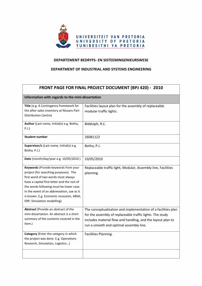
FRONT PAGE FOR FINAL PROJECT DOCUMENT (BPJ 420) - 2010
Information with regards to the mini-dissertation
Title (e.g. A Contingency framework for
the after-sales inventory at Nissans Part
Distribution Centre)
Facilities layout plan for the assembly of replaceable
modular traffic lights.
Author (Last name, Initial(s) e.g. Botha,
P.J.)
Biddulph, R.C.
Student number 26081122
Supervisor/s (Last name, Initial(s) e.g.
Botha, P.J.)
Botha, P.J.
Date (month/day/year e.g. 10/05/2010 ) 10/05/2010
Keywords (Provide keywords from your
project (for searching purposes). The
first word of two words must always
have a capital first letter and the rest of
the words following must be lower case.
In the event of an abbreviation, use as it
is known. E.g. Economic recession, ABSA,
ERP, Simulation modelling)
Replaceable traffic light, Modular, Assembly line, Facilities
planning.
Abstract (Provide an abstract of the
mini-dissertation. An abstract is a short
summary of the contents covered in the
item.)
The conceptualization and implementation of a facilities plan
for the assembly of replaceable traffic lights. The study
includes material flow and handling, and the layout plan to
run a smooth and optimal assembly line.
Category (Enter the category in which
the project was done. E.g. Operations
Research, Simulation, Logistics…)
Facilities Planning.
Declaration
1. I understand what plagiarism is and I am aware of the University's policy in this regard.
2. I declare that this is my own original work
3. Where other people's work has been used (either from a printed source, internet or any other source)
this has been carefully acknowledged and referenced in accordance with departmental requirements
4. I have not used another student's past work to hand in as my own
5. I have not allowed and will not allow, anyone to copy my work with the intention of handing it in as
his/her own work
Handtekening
Signature
Executive Summary
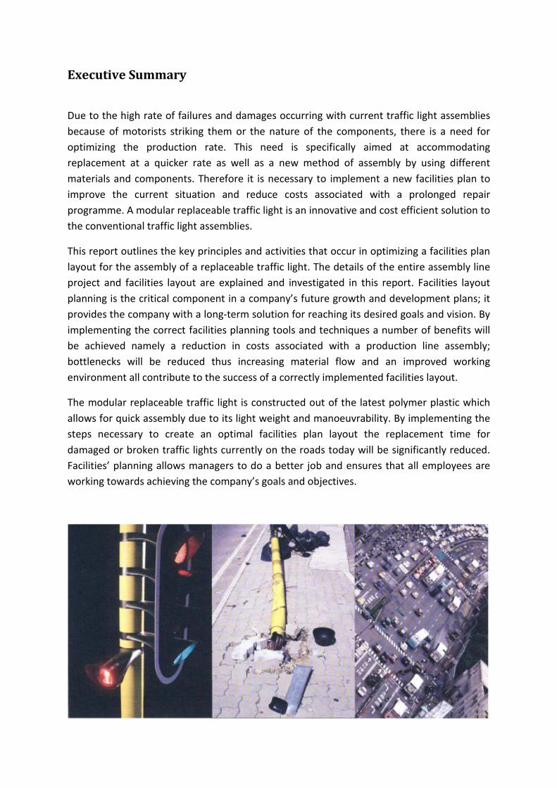
Due to the high rate of failures and damages occurring with current traffic light assemblies
because of motorists striking them or the nature of the components, there is a need for
optimizing the production rate. This need is specifically aimed at accommodating
replacement at a quicker rate as well as a new method of assembly by using different
materials and components. Therefore it is necessary to implement a new facilities plan to
improve the current situation and reduce costs associated with a prolonged repair
programme. A modular replaceable traffic light is an innovative and cost efficient solution to
the conventional traffic light assemblies.
This report outlines the key principles and activities that occur in optimizing a facilities plan
layout for the assembly of a replaceable traffic light. The details of the entire assembly line
project and facilities layout are explained and investigated in this report. Facilities layout
planning is the critical component in a company’s future growth and development plans; it
provides the company with a long-term solution for reaching its desired goals and vision. By
implementing the correct facilities planning tools and techniques a number of benefits will
be achieved namely a reduction in costs associated with a production line assembly;
bottlenecks will be reduced thus increasing material flow and an improved working
environment all contribute to the success of a correctly implemented facilities layout.
The modular replaceable traffic light is constructed out of the latest polymer plastic which
allows for quick assembly due to its light weight and manoeuvrability. By implementing the
steps necessary to create an optimal facilities plan layout the replacement time for
damaged or broken traffic lights currently on the roads today will be significantly reduced.
Facilities’ planning allows managers to do a better job and ensures that all employees are
working towards achieving the company’s goals and objectives.
Table of Contents
Executive Summary ................................................................................................................................. i
Chapter 1 ................................................................................................................................................1
1.1 Introduction and Background ...........................................................................................................1
1.2 Problem Statement...........................................................................................................................2
1.3 Project Aim and Objectives...............................................................................................................3
1.4 Project Scope ....................................................................................................................................4
Chapter 2 – Literature Review ...............................................................................................................5
2.1.1 Introduction to Facilities Planning and Design ..........................................................................5
2.1.2 Objectives of Facilities Planning.................................................................................................6
2.2 Layout Identification .........................................................................................................................6
2.2.1 Importance of Facility Layout design .........................................................................................6
2.2.2 Layout Types ..............................................................................................................................6
2.3 Material Handling and Flow..............................................................................................................8
2.3.1 Material Handling ......................................................................................................................8
2.3.2 Material Flow .............................................................................................................................9
2.4 Facility Layout Design......................................................................................................................10
2.4.1 Stages of Planning....................................................................................................................10
2.4.2 Design Process .........................................................................................................................11
2.4.3 Specifications - Workstations...................................................................................................11
2.4.4 Fixed Space Requirements.......................................................................................................12
2.5 Methods, Tools and Techniques .....................................................................................................12
2.5.1 Systematic Layout Planning .....................................................................................................13
2.5.2 The Winning Facilities Planning Process ..................................................................................17
2.6 Problem Identification and Analysis of Operations ........................................................................19
Chapter 3 – Conceptual Design and Information Gathering...............................................................22
3.1 Data Specifications..........................................................................................................................22
3.2 Conceptual Design Implementation ...............................................................................................26
3.2.1 The Layout Plan........................................................................................................................26
3.2.2 Material Flow ...........................................................................................................................27
3.2.3 Systematic Layout Planning (SLP) ............................................................................................28
3.3 Root Cause Analysis ........................................................................................................................30
Chapter 4 – Design and Problem Solving.............................................................................................31
4.1 Introduction to Plant Layout and Material Handling......................................................................31
4.2 Flow Patterns ..................................................................................................................................32
4.2.1 Measuring Flow........................................................................................................................33
4.2.1.1 Quantitative flow measurements.........................................................................................34
4.2.1.2 Qualitative Flow Measures – Activity Relationship Chart.....................................................36
4.3 Space Relationship Diagram ...........................................................................................................39
4.4 Develop Layout Alternatives...........................................................................................................41
4.5 Evaluate Alternative Facility Layout Designs ..................................................................................41
4.5.1 Weighted Factor Comparison ..................................................................................................41
4.6 Material Handling ...........................................................................................................................44
Chapter 5 – Budget...............................................................................................................................46
Chapter 6 – Recommendations and Conclusion .................................................................................47
6.1 Recommendations ......................................................................................................................47
6.2 Conclusion...................................................................................................................................47
List of References .................................................................................................................................49
Appendices ...........................................................................................................................................50
Appendix A ...........................................................................................................................................51
Capital Expenditure...............................................................................................................................51
Building costs and installation ..........................................................................................................51
New plant machinery and equipment ..............................................................................................52
New office furniture and equipment................................................................................................53
Catered for the unforeseen ..............................................................................................................53
Appendix B – Alternative Layout 1 .......................................................................................................54
Alternative Layout 1 – Second Floor.....................................................................................................55
Alternative layout 2 ..............................................................................................................................56
3D View of Assembly Plant for Replaceable Traffic Lights....................................................................57
List of Figures
Figure 2.2.1 – Alternative Types of Layouts ……………………………………………………………………………………….7
Figure 2.3.1 – Flow Planning Hierarch ……….………………………………………………………………………………………9
Figure 2.3.2 – Flow within Product Departments …………………………………………………………………………….10
Figure 2.5.1 – The Framework for Systematic Layout Planning ……………………………………………………….13
Figure 2.5.2 – An Example of a Flow-Chart .…………………………………………………………………………………….14
Figure 2.5.3 – An Example of an Activity Relationship Diagram …..………………………………………………….15
Figure 2.5.4 – An Example of a Relationship Diagram .…………………………………………………………………….15
Figure 2.5.5 – An Example of a Space Relationship Diagram …….…………………………………………………….16
Figure 2.5.6 – Alternative Block Layouts ………………………………………………………………………………………….16
Figure 2.5.7 – Winning Facilities Planning Process .………………………………………………………………………….17
Figure 2.5.8 – The Model of Success “Winning Circle” ..………………………………………….……………………….18
Figure 2.6.1 – Operation Analysis for Material Handling …………………………………………………………………20
Figure 3.1.1 – A Detailed Design of a Modular Traffic Light ….………………………………………………………….22
Figure 3.1.2 – A Detailed Diagram Illustrating an Exploded View of the Housing and Base
Plate ………………………………………..……………………………………………………………………………….24
Figure 3.1.3 – Dimensions of LED Light Bulbs ………………………………………………………………………………….25
Figure 3.2.1 – Product Planning Layout …….…………………………………………………………………………………….27
Figure 3.2.2 – End-to-end Flow ……………………………………………………………………………………………………….27
Figure 3.2.3 – Examples of Entrance and Exits Located at Opposite Side of the
Layout……………………………………………………………………………………………………..……………….28
Figure 4.2.1 – Various Flow Patterns ……………………………………………………………………………………………….33
Figure 4.2.2 – End –to –end Flow …………………………………………………………………………………………………….33
Figure 4.2.3 – Explanation of the Activity Relationship Diagram ……………………………………………………..38
Figure 4.2.4 – Activity Relationship Diagram ……………………………………………………………………………………38
Figure 4.3.1 – Systematic Layout Planning Procedure …………………………………………………………………….39
Figure 4.3.2 – Space Relationship Diagram ……………………………………………………………………………………..40
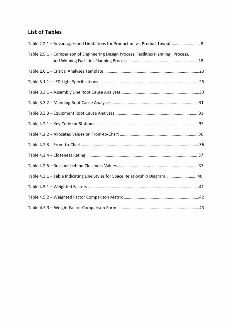
List of Tables
Table 2.2.1 – Advantages and Limitations for Production vs. Product Layout ………………………8
Table 2.5.1 – Comparison of Engineering Design Process, Facilities Planning Process,
and Winning Facilities Planning Process ..………………………………………………………18
Table 2.6.1 – Critical Analyses Template …………………………………………………………………………….20
Table 3.1.1 – LED Light Specifications …………………………………………………………………………………25
Table 3.3.1 – Assembly Line Root Cause Analyses ………………………………………………………………30
Table 3.3.2 – Manning Root Cause Analyses ………………………………………………………………………31
Table 3.3.3 – Equipment Root Cause Analyses …………………………………………………………………..31
Table 4.2.1 – Key Code for Stations ..………………………………………………………………………………….35
Table 4.2.2 – Allocated values on From-to-Chart ….……………………………………………………………36
Table 4.2.3 – From-to-Chart ……………………………………………………………………………………………….36
Table 4.2.4 – Closeness Rating …………………………………………………………………………………………..37
Table 4.2.5 – Reasons behind Closeness Values …………………………………………………………………37
Table 4.3.1 – Table Indicating Line Styles for Space Relationship Diagram ………………………..40
Table 4.5.1 – Weighted Factors ………………………………………………………………………………………….41
Table 4.5.2 – Weighted Factor Comparison Matrix …………………………………………………………….42
Table 4.5.3 – Weight Factor Comparison Form ………………………………………………………………….43
1
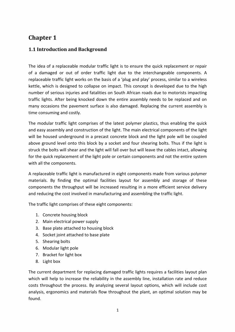
Chapter 1
1.1 Introduction and Background
The idea of a replaceable modular traffic light is to ensure the quick replacement or repair
of a damaged or out of order traffic light due to the interchangeable components. A
replaceable traffic light works on the basis of a ‘plug and play’ process, similar to a wireless
kettle, which is designed to collapse on impact. This concept is developed due to the high
number of serious injuries and fatalities on South African roads due to motorists impacting
traffic lights. After being knocked down the entire assembly needs to be replaced and on
many occasions the pavement surface is also damaged. Replacing the current assembly is
time consuming and costly.
The modular traffic light comprises of the latest polymer plastics, thus enabling the quick
and easy assembly and construction of the light. The main electrical components of the light
will be housed underground in a precast concrete block and the light pole will be coupled
above ground level onto this block by a socket and four shearing bolts. Thus if the light is
struck the bolts will shear and the light will fall over but will leave the cables intact, allowing
for the quick replacement of the light pole or certain components and not the entire system
with all the components.
A replaceable traffic light is manufactured in eight components made from various polymer
materials. By finding the optimal facilities layout for assembly and storage of these
components the throughput will be increased resulting in a more efficient service delivery
and reducing the cost involved in manufacturing and assembling the traffic light.
The traffic light comprises of these eight components:
1. Concrete housing block
2. Main electrical power supply
3. Base plate attached to housing block
4. Socket joint attached to base plate
5. Shearing bolts
6. Modular light pole
7. Bracket for light box
8. Light box
The current department for replacing damaged traffic lights requires a facilities layout plan
which will help to increase the reliability in the assembly line, installation rate and reduce
costs throughout the process. By analyzing several layout options, which will include cost
analysis, ergonomics and materials flow throughout the plant, an optimal solution may be
found.
2
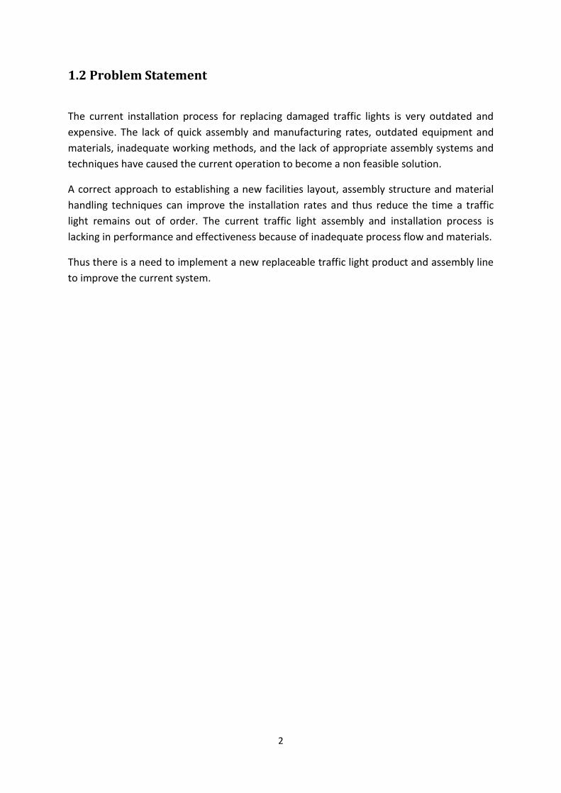
1.2 Problem Statement
The current installation process for replacing damaged traffic lights is very outdated and
expensive. The lack of quick assembly and manufacturing rates, outdated equipment and
materials, inadequate working methods, and the lack of appropriate assembly systems and
techniques have caused the current operation to become a non feasible solution.
A correct approach to establishing a new facilities layout, assembly structure and material
handling techniques can improve the installation rates and thus reduce the time a traffic
light remains out of order. The current traffic light assembly and installation process is
lacking in performance and effectiveness because of inadequate process flow and materials.
Thus there is a need to implement a new replaceable traffic light product and assembly line
to improve the current system.
3
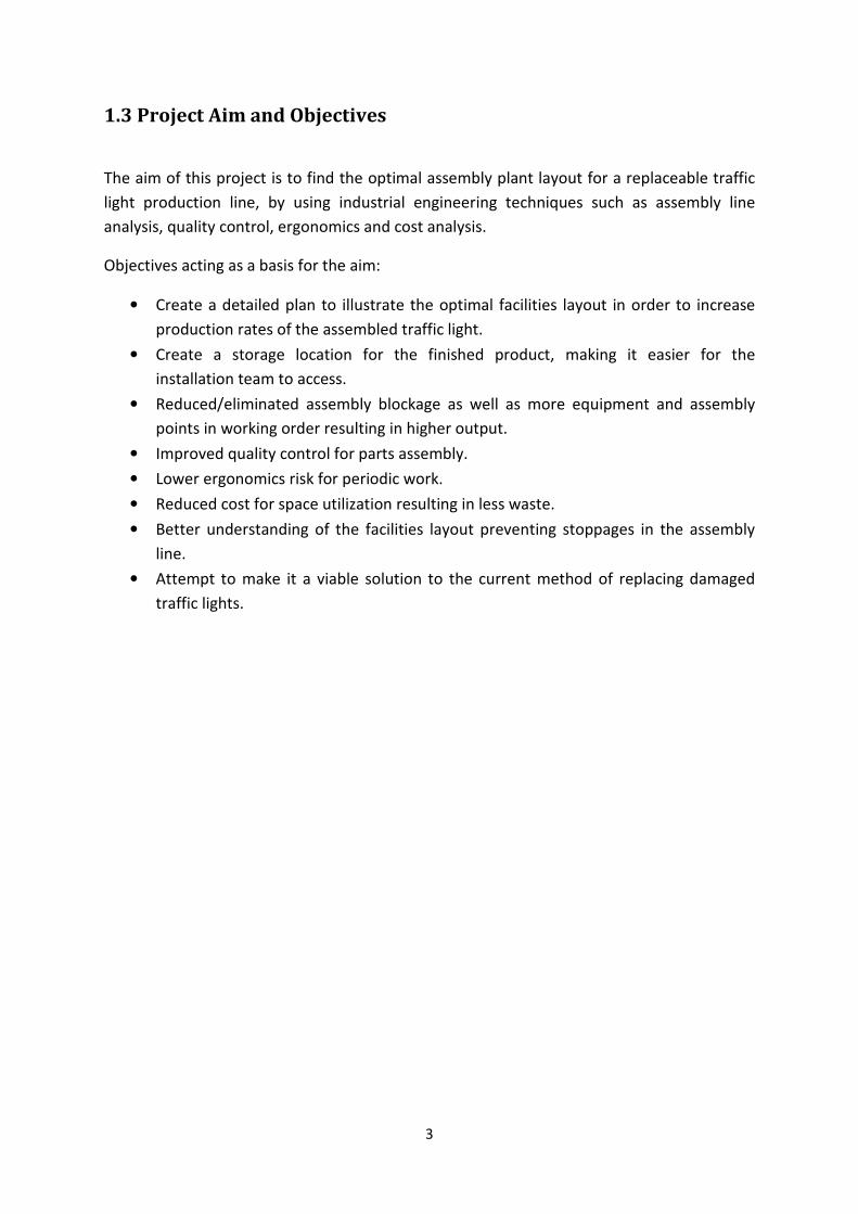
1.3 Project Aim and Objectives
The aim of this project is to find the optimal assembly plant layout for a replaceable traffic
light production line, by using industrial engineering techniques such as assembly line
analysis, quality control, ergonomics and cost analysis.
Objectives acting as a basis for the aim:
• Create a detailed plan to illustrate the optimal facilities layout in order to increase
production rates of the assembled traffic light.
• Create a storage location for the finished product, making it easier for the
installation team to access.
• Reduced/eliminated assembly blockage as well as more equipment and assembly
points in working order resulting in higher output.
• Improved quality control for parts assembly.
• Lower ergonomics risk for periodic work.
• Reduced cost for space utilization resulting in less waste.
• Better understanding of the facilities layout preventing stoppages in the assembly
line.
• Attempt to make it a viable solution to the current method of replacing damaged
traffic lights.
4
1.4 Project Scope
The first section of the project will entail an in-depth literature review. This will demonstrate
the techniques used in determining the optimal layout plan and will determine if it is a
viable solution that can be implemented at a relatively low cost. Alternative layout plans will
be identified and investigated. The literature review will also focus on identifying current
and similar solutions and methods of replaceable traffic lights and analyse the impact they
have had on the service delivery sector and what they entail.
For the second part of the project the identified alternative layout plans will be analysed to
determine the best layout plan. This chosen facilities layout plan will be refined to make it a
viable solution and a working plan that can be implemented in the current service delivery
environment. It will be important to implement various methods and techniques to make
this a justifiable model with significant and improved results.
The project will not entail the actual manufacturing of the components from various
materials but mainly on how the components will be assembled together and the structure
needed to optimize the plant layout to improve throughput and reduce the costs involved in
the assembly line and the facilities layout.
5
Chapter 2 – Literature Review
2.1.1 Introduction to Facilities Planning and Design
Facilities’ planning has become a critical component for companies to keep up with the
current market trends in the last few years. In the past facilities planning was primarily
considered to be a science. In today’s competitive global marketplace, facilities’ planning
has become a strategy, (Tompkins et al, 2003).
Facilities’ planning is a strategy used to achieve supply chain excellence. It is concerned with
the design, layout and accommodation of various categories within a business environment.
The main requirement for any facilities planning project to be successful is its ability to
adapt and become suitable for new use. By implementing facilities planning in an assembly
line a greater rate of production and throughput will be achieved.
Design, layout, accommodation of people, machines and activities of a system or enterprise
within a physically restricted environment are the primary concerns for facilities planning.
Haung (2003) states that facility layout design determines how to arrange, locate, and
distribute the equipment and support activities in an assembly line facility to achieve overall
production and the increase of assembly output.
An optimal facilities layout plan contributes to the overall efficiency of assembly operations
and can reduce up to 50% of the total operating expenses, (Tompkins and White, 2003).
When deciding on an optimal facilities layout structure, basic principles must be used. The
necessary tools and methods required to optimize a facilities layout plant vary depending on
the type of operation at hand.
According to Tompkins (Tompkins et al, 2003), the following are common reasons for the
redesigning of facilities:
• Material handling problems, bottlenecks and high costs that normally occur due to
inefficient layouts.
• Introducing of a new service or product.
• Changes in assembly methods, processes or equipment.
• Changes in legal requirements or environmental requirements.
Due to the high demand for replacing traffic lights there is an ever increasing pressure to
improve and deliver products on time. However the quality of the product must not be
compromised and thus finding an optimal facilities layout plan is critical for the assembly of
replaceable traffic lights.
6
2.1.2 Objectives of Facilities Planning
The facilities planning objectives as defined in Tompkins and White, (2003) are to:
• Increase return on assets (ROA) by maximizing inventory turns, minimizing obsolete
inventory, maximizing employee participation, and maximizing continuous
improvement
• Improve customer satisfaction by delivering products on time and ensuring the
quality adheres to the customer’s specifications.
• Reduce costs and increase the assembly lines profitability
• Form an integrated supply chain by using partnerships and communication
• Effectively utilize people, equipment, space and energy
2.2 Layout Identification
2.2.1 Importance of Facility Layout design
The overall effectiveness of an assembly line can be greatly affected by insufficient layouts
or facility layout problems which can occur in many ways. A study done by Tompkins,
(1996), shows that since 1955, at least 10% to 30% of material handling costs can be
reduced by an effective facilities layout plan. The vast amount of capital invested into
facilities planning each year makes this an important aspect.
2.2.2 Layout Types
When analyzing, designing and implementing certain solutions to problems identified on an
assembly line, it is critical to evaluate the requirements and activities for each type of
scenario in order to make an informed decision.
Facilities’ planning focuses on four main layout types namely, (Tompkins and White, 2003);
• Fixed material layout
• Production line layout
• Product family layout
• Process layout
7
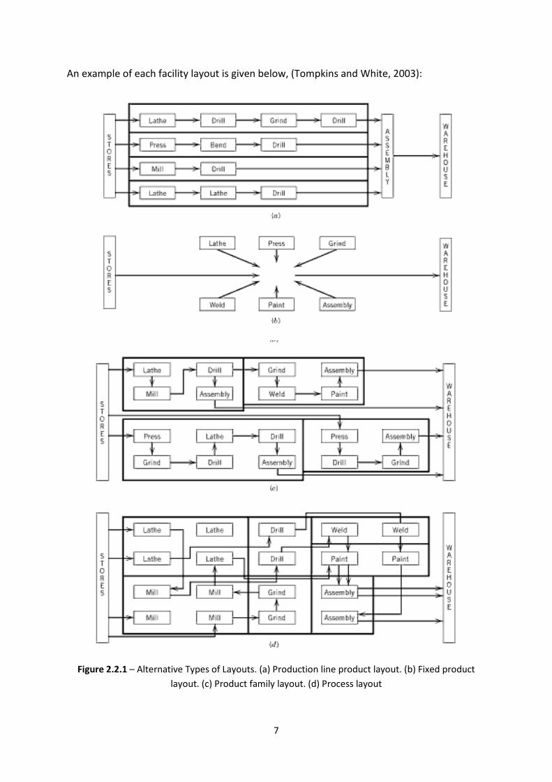
An example of each facility layout is given below, (Tompkins and White, 2003):
Figure 2.2.1 – Alternative Types of Layouts. (a) Production line product layout. (b) Fixed product
layout. (c) Product family layout. (d) Process layout
8
For an assembly line project, such as assembling a replaceable traffic light, the two main
layout plans that will be focused on are the production line layout and the product family
layout. The production line facility is implemented if there is a large, stable demand for
standardized products, whereas the product family facility focuses on a medium demand for
a medium number of similar components.
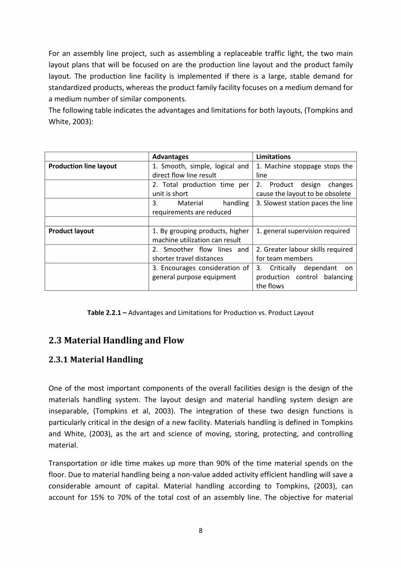
The following table indicates the advantages and limitations for both layouts, (Tompkins and
White, 2003):
Advantages Limitations
Production line layout 1. Smooth, simple, logical and
direct flow line result
1. Machine stoppage stops the
line
2. Total production time per
unit is short
2. Product design changes
cause the layout to be obsolete
3. Material handling
requirements are reduced
3. Slowest station paces the line
Product layout 1. By grouping products, higher
machine utilization can result
1. general supervision required
2. Smoother flow lines and
shorter travel distances
2. Greater labour skills required
for team members
3. Encourages consideration of
general purpose equipment
3. Critically dependant on
production control balancing
the flows
Table 2.2.1 – Advantages and Limitations for Production vs. Product Layout
2.3 Material Handling and Flow
2.3.1 Material Handling
One of the most important components of the overall facilities design is the design of the
materials handling system. The layout design and material handling system design are
inseparable, (Tompkins et al, 2003). The integration of these two design functions is
particularly critical in the design of a new facility. Materials handling is defined in Tompkins
and White, (2003), as the art and science of moving, storing, protecting, and controlling
material.
Transportation or idle time makes up more than 90% of the time material spends on the
floor. Due to material handling being a non-value added activity efficient handling will save a
considerable amount of capital. Material handling according to Tompkins, (2003), can
account for 15% to 70% of the total cost of an assembly line. The objective for material
9
handling is to simplify and eliminate material handling activities, thus reducing the
operational costs by 15% to 30% according to Tompkins and White, (2003).
The objectives of material handling, (Tompkins et al, 2003), are as follows:
• Increase efficiency of material flow
• Increase productivity
• Improve safety and working conditions
• Reduce material handling costs
• Improve facility utilization
• Facilitate the assembly process
2.3.2 Material Flow
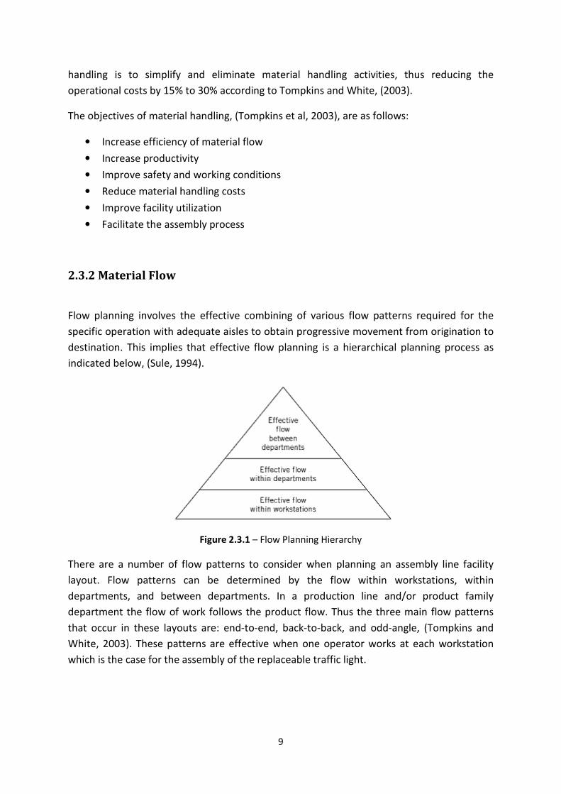
Flow planning involves the effective combining of various flow patterns required for the
specific operation with adequate aisles to obtain progressive movement from origination to
destination. This implies that effective flow planning is a hierarchical planning process as
indicated below, (Sule, 1994).
Figure 2.3.1 – Flow Planning Hierarchy
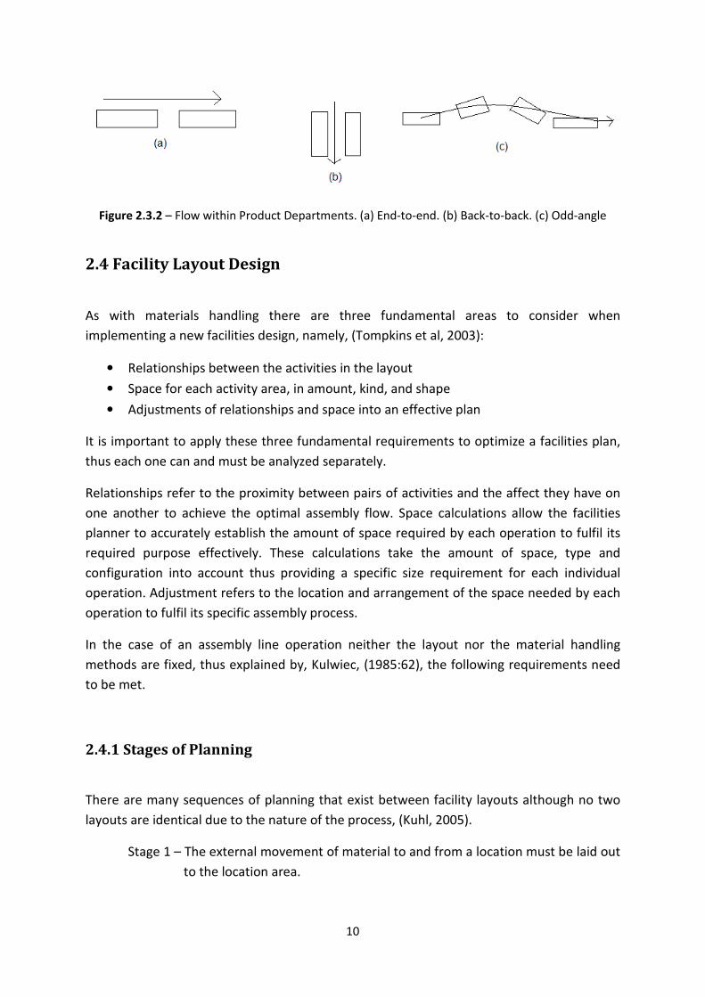
There are a number of flow patterns to consider when planning an assembly line facility
layout. Flow patterns can be determined by the flow within workstations, within
departments, and between departments. In a production line and/or product family
department the flow of work follows the product flow. Thus the three main flow patterns
that occur in these layouts are: end-to-end, back-to-back, and odd-angle, (Tompkins and
White, 2003). These patterns are effective when one operator works at each workstation
which is the case for the assembly of the replaceable traffic light.
10
Figure 2.3.2 – Flow within Product Departments. (a) End-to-end. (b) Back-to-back. (c) Odd-angle
2.4 Facility Layout Design
As with materials handling there are three fundamental areas to consider when
implementing a new facilities design, namely, (Tompkins et al, 2003):
• Relationships between the activities in the layout
• Space for each activity area, in amount, kind, and shape
• Adjustments of relationships and space into an effective plan
It is important to apply these three fundamental requirements to optimize a facilities plan,
thus each one can and must be analyzed separately.
Relationships refer to the proximity between pairs of activities and the affect they have on
one another to achieve the optimal assembly flow. Space calculations allow the facilities
planner to accurately establish the amount of space required by each operation to fulfil its
required purpose effectively. These calculations take the amount of space, type and
configuration into account thus providing a specific size requirement for each individual
operation. Adjustment refers to the location and arrangement of the space needed by each
operation to fulfil its specific assembly process.
In the case of an assembly line operation neither the layout nor the material handling
methods are fixed, thus explained by, Kulwiec, (1985:62), the following requirements need
to be met.
2.4.1 Stages of Planning
There are many sequences of planning that exist between facility layouts although no two
layouts are identical due to the nature of the process, (Kuhl, 2005).
Stage 1 – The external movement of material to and from a location must be laid out
to the location area.
11
Stage 2 – An overall plan for the blocked out layout and overall handling plan for the
total area.
Stage 3 – Detailed layouts for each specific piece of machinery, equipment or storage
area, and specific handling methods.
Stage 4 – Installation of approved plans, procurement and/or rearrangement.
2.4.2 Design Process
Only once an optimal facilities plan exists can further improvements and changes be made.
The overall layout sets out to achieve the best possible results concerning various
components in optimizing the assembly line. Some of these components include, (Tompkins
et al 2003:108):
1. Operator must be able to collect or discharge materials without having to make
awkward reaches or travel long distances.
2. The operator should be involved efficiently in the workplace to perform the required
operation.
3. The time spent on handling the material during assembly should be minimized.
4. A continuous wok flow should exist within the workstation to minimize cycle and
idle times.
2.4.3 Specifications - Workstations
Workstations for materials areas should consist of the following, (Tompkins and White,
2003):
1. Receiving and storing of inbound materials
2. In-process materials
3. Storing outbound materials and shipping
4. Storing and shipping waste and scrap
5. Tools, fixtures, jigs, dies and maintenance materials
Included in the workstation space requirements is the space for the personal area:
1. The operator(s)
2. Material Handling
3. Operator ingress and regress
12
2.4.4 Fixed Space Requirements
Each workstation requirements should be incorporated into the facilities layout plan. Paths
assigned to forklifts included a minimum of 2.75 metres for the specified forklift operating
on the assembly line, (Tompkins et al, 2003). An important fixed space requirement is the
consideration of the entry and exit points to determine which flow patterns to use.
Accessibility to certain areas is critical, including minimal allowed aisle space within the
storage areas and material handling equipment areas, (Tompkins and White, 2003).
Accessibility to each workstation by an individual should also be provided for in the layout
plan.
2.5 Methods, Tools and Techniques
There are several approaches to be considered when implementing a facilities layout plan. A
facility planning process is understood to be a life cycle, although only planned once it is
frequently replanned and improved to satisfy its continuously changing objectives.
The traditional engineering design process is the simplest method for optimizing a facility
plan, however all methods have similar steps to this process which include:
1. Define the problem
2. Analyze the problem
3. Determine the space requirements for all activities and generate alternative designs
4. Evaluate the alternatives
5. Select the preferred design
6. Implement the design
When implementing a facility planning project there are two popular and effective
approaches to consider, the Systematic Layout Planning (SLP) method by Richard Muther
and the Winning Facilities Planning Process.
13
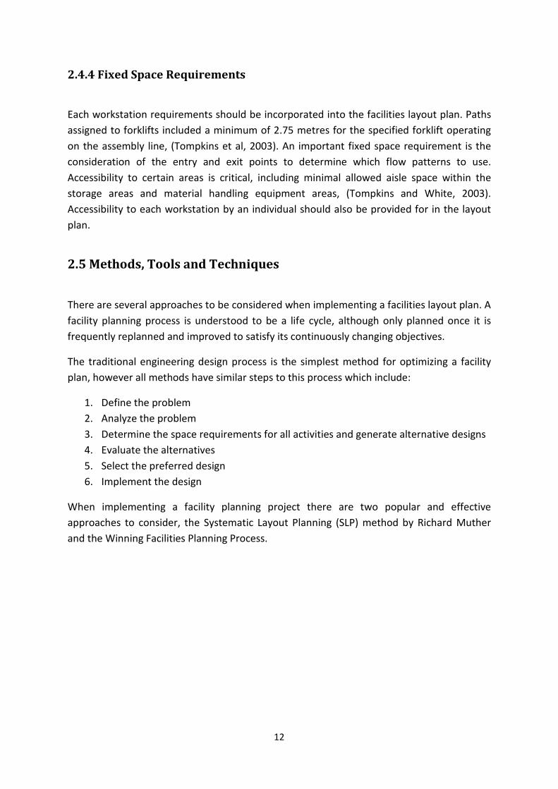
2.5.1 Systematic Layout Planning
Muther’s Systematic Layout Planning (SLP) Procedure
Figure 2.5.1 – The Framework for Systematic Layout Planning (SLP), (Tompkins, White, Bozer,
Tranchoco, 3rd
edition, 2003)
Muther implements the following steps in his layout design process:
1. Document the present operation by applying flow charts to document the material
and information flow. In addition, the present equipment layout and current
methods must be documented. The flow chart will indicate steps that are redundant
or may no longer be necessary. Steps that will improve the operation may be added.
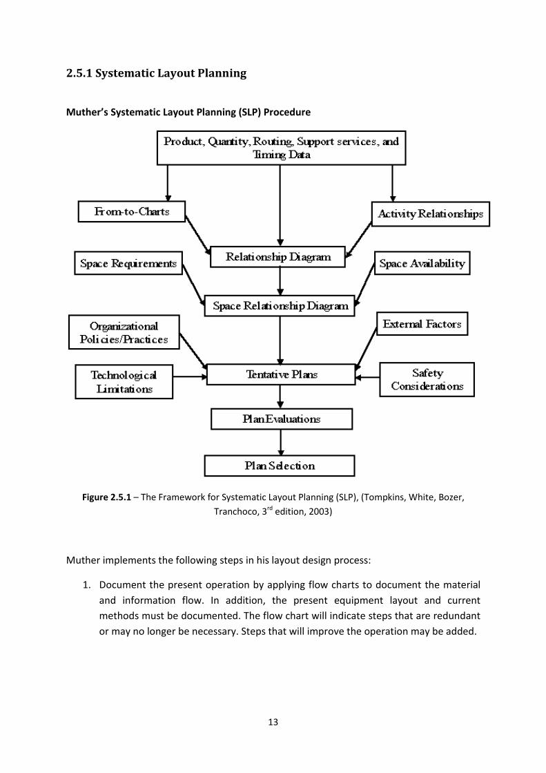
14
Figure 2.5.2 – An Example of a Flow-Chart taken from (Baeseman, 2003)
2. Define the activities within the present process and include future operations.
Activities are operations, equipment, workstations, or areas that make up the space
that is being planned. In this step an activity relationship chart is used to link all
necessary activities. A relationship diagram is then produced to position activities
spatially. Proximities are typically used to reflect the relationships between pairs of
activities. Thus the following examples taken from, Tompkins et al (2003), indicate
the relationships between various operations.
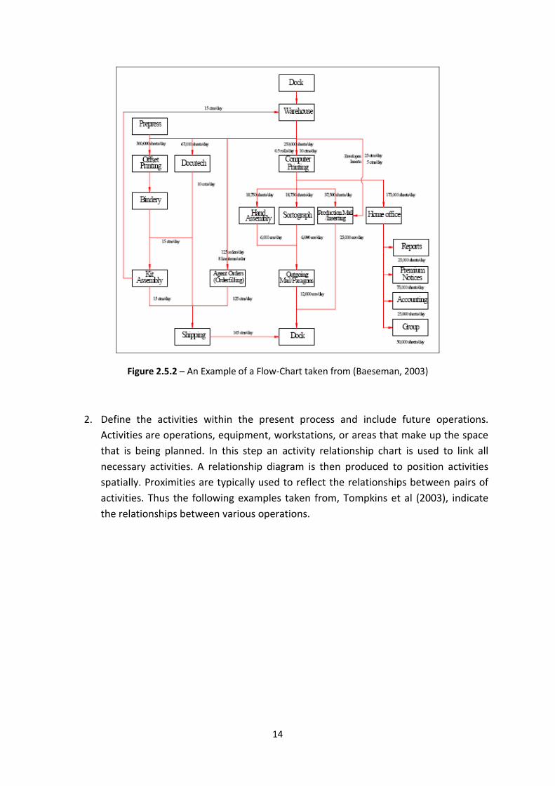
15
Figure 2.5.3 – An Example of an Activity Relationship Diagram
Figure 2.5.4 – An Example of a Relationship Diagram
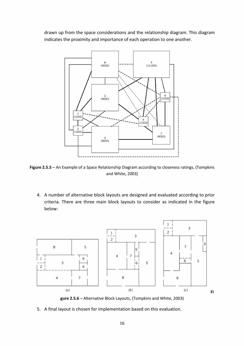
3. Develop space requirements in terms of size, equipment, and operational
improvements for each activity. It is necessary to look at each activity individually as
these requirements vary from activity to activity. The space relationship diagram is
16
drawn up from the space considerations and the relationship diagram. This diagram
indicates the proximity and importance of each operation to one another.
Figure 2.5.5 – An Example of a Space Relationship Diagram according to closeness ratings, (Tompkins
and White, 2003)
4. A number of alternative block layouts are designed and evaluated according to prior
criteria. There are three main block layouts to consider as indicated in the figure
below:
Fi
gure 2.5.6 – Alternative Block Layouts, (Tompkins and White, 2003)
5. A final layout is chosen for implementation based on this evaluation.
17
2.5.2 The Winning Facilities Planning Process
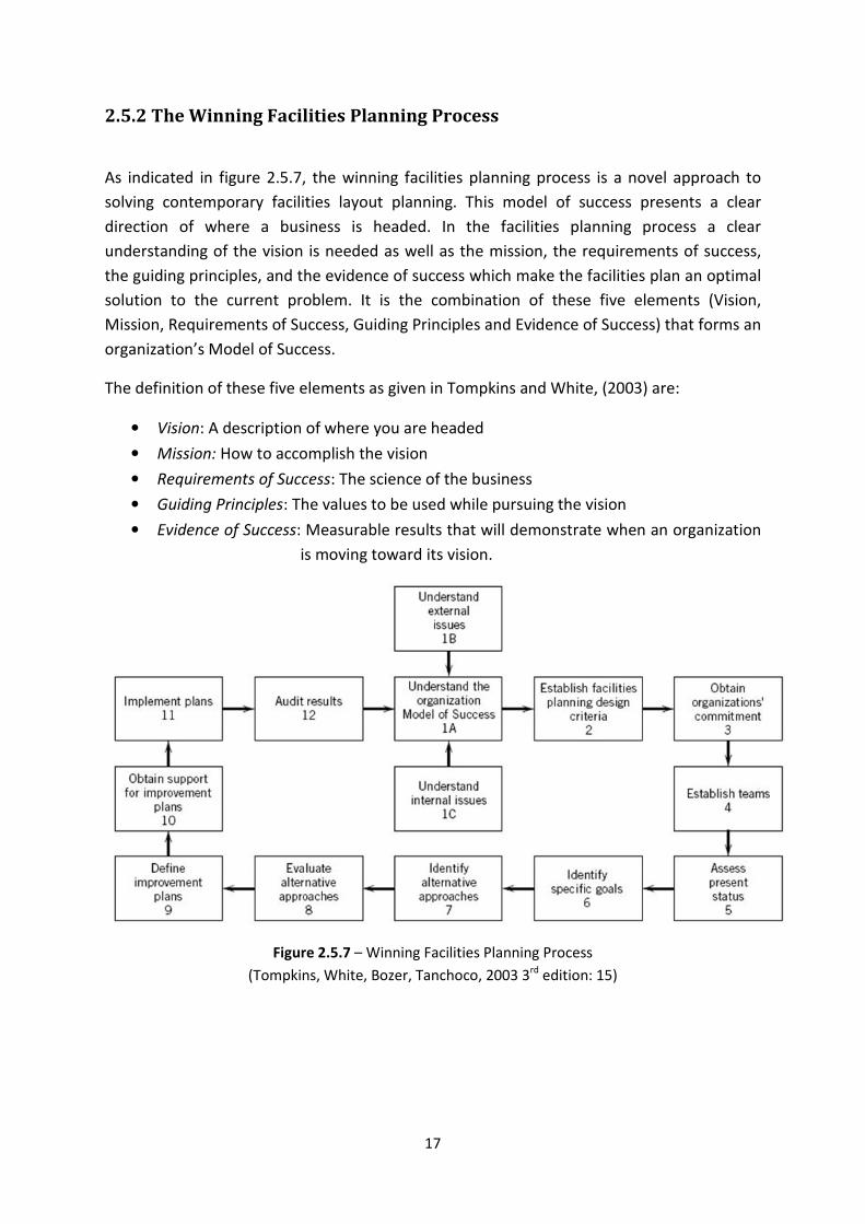
As indicated in figure 2.5.7, the winning facilities planning process is a novel approach to
solving contemporary facilities layout planning. This model of success presents a clear
direction of where a business is headed. In the facilities planning process a clear
understanding of the vision is needed as well as the mission, the requirements of success,
the guiding principles, and the evidence of success which make the facilities plan an optimal
solution to the current problem. It is the combination of these five elements (Vision,
Mission, Requirements of Success, Guiding Principles and Evidence of Success) that forms an
organization’s Model of Success.
The definition of these five elements as given in Tompkins and White, (2003) are:
• Vision: A description of where you are headed
• Mission: How to accomplish the vision
• Requirements of Success: The science of the business
• Guiding Principles: The values to be used while pursuing the vision
• Evidence of Success: Measurable results that will demonstrate when an organization
is moving toward its vision.
Figure 2.5.7 – Winning Facilities Planning Process
(Tompkins, White, Bozer, Tanchoco, 2003 3rd
edition: 15)
18
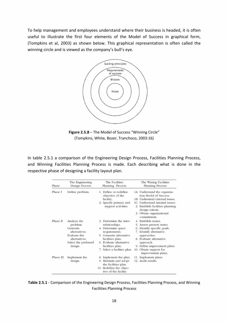
To help management and employees understand where their business is headed, it is often
useful to illustrate the first four elements of the Model of Success in graphical form,
(Tompkins et al, 2003) as shown below. This graphical representation is often called the
winning circle and is viewed as the company’s bull’s eye.
Figure 2.5.8 – The Model of Success “Winning Circle”
(Tompkins, White, Bozer, Tranchoco, 2003:16)
In table 2.5.1 a comparison of the Engineering Design Process, Facilities Planning Process,
and Winning Facilities Planning Process is made. Each describing what is done in the
respective phase of designing a facility layout plan.
Table 2.5.1 - Comparison of the Engineering Design Process, Facilities Planning Process, and Winning
Facilities Planning Process
19
2.6 Problem Identification and Analysis of Operations
According to Niebel, B. & Freivalds, A. (Niebel et al, 2003) the root cause analysis and critical
analysis techniques are necessary steps that must be taken at the start of a project for it to
have an orderly approach and allows the project to end with the implementation of the final
design.
If these methods are implemented and executed correctly, the facts can be presented
clearly and accurately. The methods can then be examined critically to identify the most
practical, economical, and effective facilities plan which can be installed, (Niebel et al,
2003).
Wikipedia, (Wikipedia, 2008) states that Root Cause Analysis is a class of problem solving
techniques aimed at identifying the root causes of problems or events. It is a problem
solving technique structured to investigate and identify the true cause of a problem and the
necessary actions needed to be taken to eliminate it.
By implementing a critical analysis approach throughout the assembly line will allow for
inspections of standards, material handling, working methods and conditions, and tool
equipment.
When implementing a new facilities design with new material handling techniques it is
important to analysis the system critical thus allowing for the appropriate improvements to
be made. According to Niebel and Freivalds (Niebel et al, 2003), method analysts use
operation analysis to increase productivity per unit of time by means of studying all
productive and non-productive operations of a system. By using the questioning approach
on all operations of the facility an efficient facilities layout plan can be developed.
Eliminating inefficient material handling processes without sacrificing safety can be achieved
through analyzing the entire system critically. The Material Handling Institute (1998) has
developed 10 principles of material handling, these are:
• Planning principle
• Work principle
• Unit load principle
• Space utilization principle
• Automation principle
• Standardization principle
• Ergonomic principle
• Life-cycle-cost principle
• System principle
• Environment principle
20
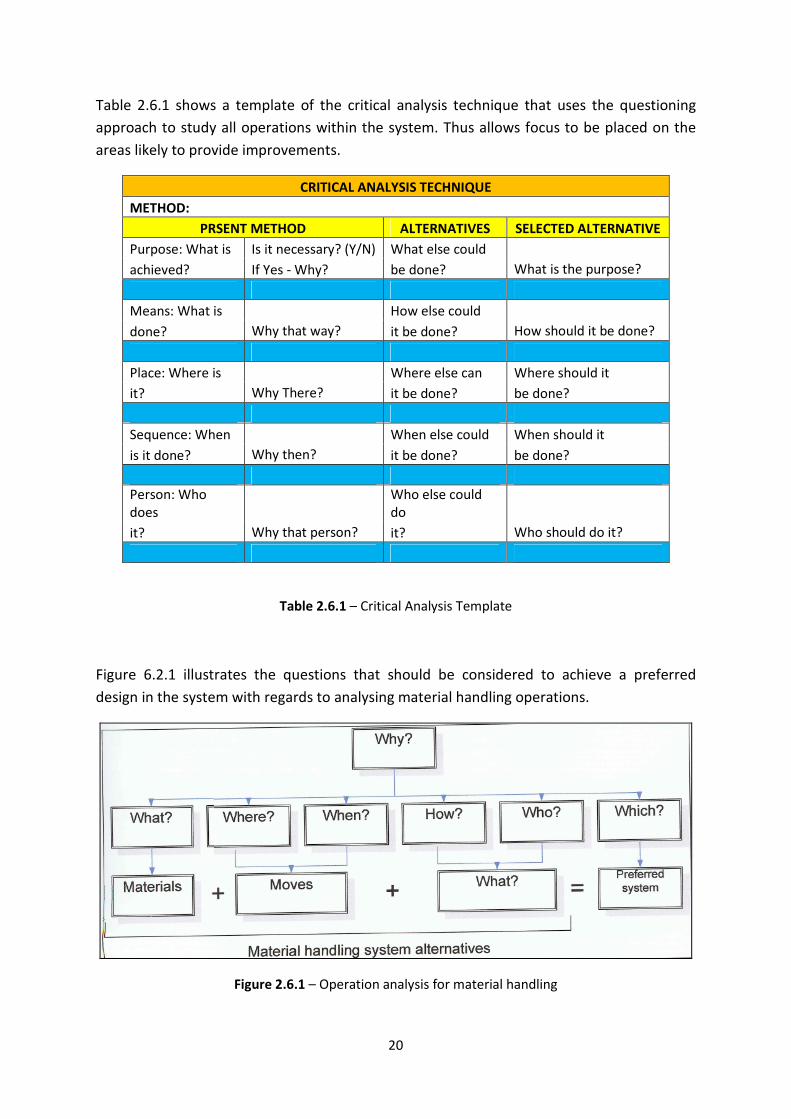
Table 2.6.1 shows a template of the critical analysis technique that uses the questioning
approach to study all operations within the system. Thus allows focus to be placed on the
areas likely to provide improvements.
CRITICAL ANALYSIS TECHNIQUE
METHOD:
PRSENT METHOD ALTERNATIVES SELECTED ALTERNATIVE
Purpose: What is Is it necessary? (Y/N) What else could
achieved? If Yes - Why? be done? What is the purpose?
Means: What is How else could
done? Why that way? it be done? How should it be done?
Place: Where is Where else can Where should it
it? Why There? it be done? be done?
Sequence: When When else could When should it
is it done? Why then? it be done? be done?
Person: Who
does
Who else could
do
it? Why that person? it? Who should do it?
Table 2.6.1 – Critical Analysis Template
Figure 6.2.1 illustrates the questions that should be considered to achieve a preferred
design in the system with regards to analysing material handling operations.
Figure 2.6.1 – Operation analysis for material handling
21
Niebel, B. & Freivalds, A. (Niebel et al, 2003) predetermined 9 primary operation analysis
approaches that the critical analysis is based on:
1. Operational Purpose
2. Part Design
3. Tolerances and Specifications
4. Material
5. Manufacturing Sequence and Process
6. Set-up and Tools
7. Material Handling
8. Plant Layout
9. Work Design
Not all of these approaches are applicable to each operation within the system. Using the
correct approach, overall improvements can be achieved and finding an optimal plant layout
can become possible. Niebel, B (Niebel et al), states that whenever this procedure is
followed by competent engineers and analysts, beneficial results have been achieved.
22
Chapter 3 – Conceptual Design and Information Gathering
3.1 Data Specifications
It is important to note that the modular replaceable traffic light is a new design feature for
traffic lights and does not exist in assembly at this present time, thus there is no current
facility layout plan and ideas put forward in this project are based on guidelines and
advantages of one application over another.
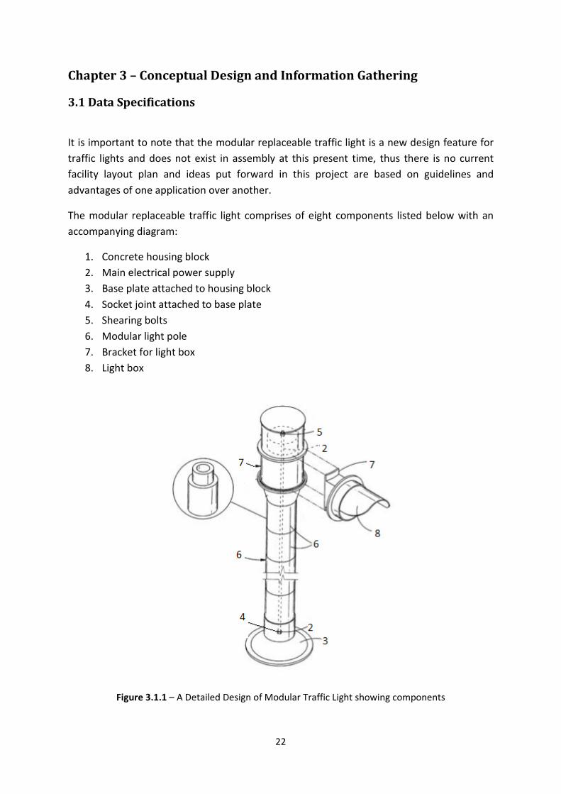
The modular replaceable traffic light comprises of eight components listed below with an
accompanying diagram:
1. Concrete housing block
2. Main electrical power supply
3. Base plate attached to housing block
4. Socket joint attached to base plate
5. Shearing bolts
6. Modular light pole
7. Bracket for light box
8. Light box
Figure 3.1.1 – A Detailed Design of Modular Traffic Light showing components
23
The concrete housing block, light box and light pole are outsourced components from
various suppliers. Once these components are all stored together in the arrivals storage unit
of the facility the assembly line can begin to assembly the parts in a straight line material
flow pattern.
The following specifications are an initial guideline to the various components to indicate
the space required for assembly:
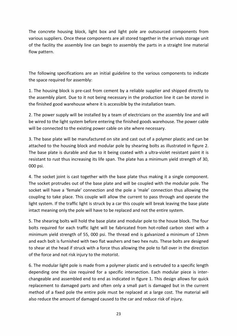
1. The housing block is pre-cast from cement by a reliable supplier and shipped directly to
the assembly plant. Due to it not being necessary in the production line it can be stored in
the finished good warehouse where it is accessible by the installation team.
2. The power supply will be installed by a team of electricians on the assembly line and will
be wired to the light system before entering the finished goods warehouse. The power cable
will be connected to the existing power cable on site where necessary.
3. The base plate will be manufactured on site and cast out of a polymer plastic and can be
attached to the housing block and modular pole by shearing bolts as illustrated in figure 2.
The base plate is durable and due to it being coated with a ultra-violet resistant paint it is
resistant to rust thus increasing its life span. The plate has a minimum yield strength of 30,
000 psi.
4. The socket joint is cast together with the base plate thus making it a single component.
The socket protrudes out of the base plate and will be coupled with the modular pole. The
socket will have a ‘female’ connection and the pole a ‘male’ connection thus allowing the
coupling to take place. This couple will allow the current to pass through and operate the
light system. If the traffic light is struck by a car this couple will break leaving the base plate
intact meaning only the pole will have to be replaced and not the entire system.
5. The shearing bolts will hold the base plate and modular pole to the house block. The four
bolts required for each traffic light will be fabricated from hot-rolled carbon steel with a
minimum yield strength of 55, 000 psi. The thread end is galvanized a minimum of 12mm
and each bolt is furnished with two flat washers and two hex nuts. These bolts are designed
to shear at the head if struck with a force thus allowing the pole to fall over in the direction
of the force and not risk injury to the motorist.
6. The modular light pole is made from a polymer plastic and is extruded to a specific length
depending one the size required for a specific intersection. Each modular piece is inter-
changeable and assembled end to end as indicated in figure 1. This design allows for quick
replacement to damaged parts and often only a small part is damaged but in the current
method of a fixed pole the entire pole must be replaced at a large cost. The material will
also reduce the amount of damaged caused to the car and reduce risk of injury.
24
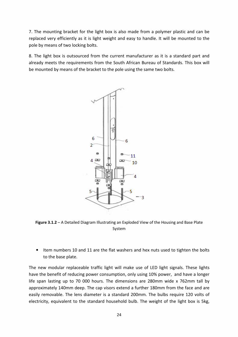
7. The mounting bracket for the light box is also made from a polymer plastic and can be
replaced very efficiently as it is light weight and easy to handle. It will be mounted to the
pole by means of two locking bolts.
8. The light box is outsourced from the current manufacturer as it is a standard part and
already meets the requirements from the South African Bureau of Standards. This box will
be mounted by means of the bracket to the pole using the same two bolts.
Figure 3.1.2 – A Detailed Diagram Illustrating an Exploded View of the Housing and Base Plate
System
• Item numbers 10 and 11 are the flat washers and hex nuts used to tighten the bolts
to the base plate.
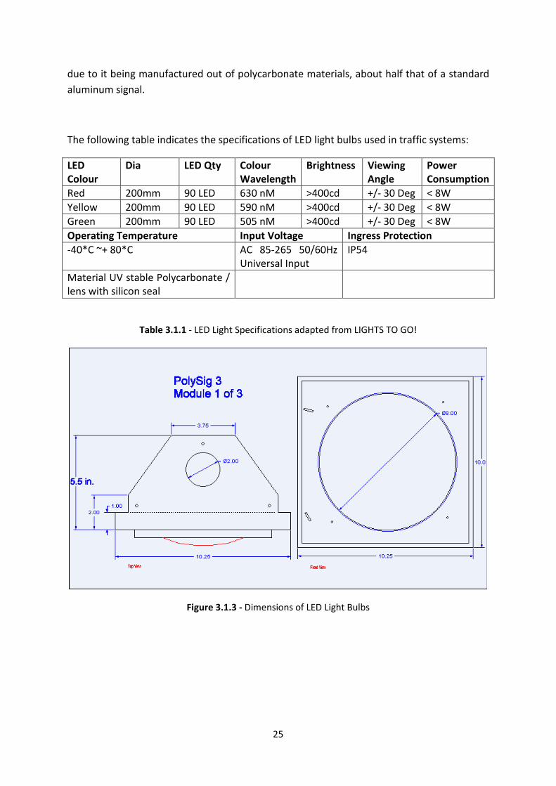
The new modular replaceable traffic light will make use of LED light signals. These lights
have the benefit of reducing power consumption, only using 10% power, and have a longer
life span lasting up to 70 000 hours. The dimensions are 280mm wide x 762mm tall by
approximately 140mm deep. The cap visors extend a further 180mm from the face and are
easily removable. The lens diameter is a standard 200mm. The bulbs require 120 volts of
electricity, equivalent to the standard household bulb. The weight of the light box is 5kg,
25
due to it being manufactured out of polycarbonate materials, about half that of a standard
aluminum signal.
The following table indicates the specifications of LED light bulbs used in traffic systems:
LED
Colour
Dia LED Qty Colour
Wavelength
Brightness Viewing
Angle
Power
Consumption
Red 200mm 90 LED 630 nM >400cd +/- 30 Deg < 8W
Yellow 200mm 90 LED 590 nM >400cd +/- 30 Deg < 8W
Green 200mm 90 LED 505 nM >400cd +/- 30 Deg < 8W
Operating Temperature Input Voltage Ingress Protection
-40*C ~+ 80*C AC 85-265 50/60Hz
Universal Input
IP54
Material UV stable Polycarbonate /
lens with silicon seal
Table 3.1.1 - LED Light Specifications adapted from LIGHTS TO GO!
Figure 3.1.3 - Dimensions of LED Light Bulbs
26
3.2 Conceptual Design Implementation
The design of a new facility must be done in sectors. Each sector must be analyzed and
solved to completion individually, once this is done all sectors can be assembled together to
create the final layout. This process is done according to the functional and physical
requirements of each activity on the assembly line.
The following aspects that will be analyzed individually are:
• The layout plan
• Material handling
• Material flow
Once these aspects are finalised they will be incorporated into Muther’s Systematic Layout
Planning (SLP) methodology as it is the most comprehensive and detailed method when
building a facilities layout for an assembly line process. However Muther’s methodology will
not be followed exclusively as no two assembly layouts are identical, thus various aspects of
different design processes will be used to optimize the layout plan for the assembling of
replaceable traffic lights.
3.2.1 The Layout Plan
There are two main facilities layout options to consider when trying to optimize an assembly
line production plant. A production/process line layout is based on the processing sequence
for the parts being produced on the assembly line. When there exists a large demand for
standardized products and the materials flow from one workstation directly to the next in a
straight line this layout allows for the workstations to be combined into a single department
producing a single product. This layout allows for the parts to flow without disruptions
resulting in high output numbers.
When there is a medium demand for similar components to be assembled the components
can be grouped to form a product family. The combination of grouping similar workstations
results in a product planning department that is interlinked based on common process
sequences, tooling requirements or material composition thus resulting in a high degree of
intradepartmental flow.
As indicated in table 2.2.1 in chapter 2, there are advantages to using both these layouts as
properties of both these layouts are prevalent in an assembly line. Reid et al (2007) classifies
an assembly line as a Hybrid Layout which combines elements of both the process and
product layout into a more effective and optimal layout.
27
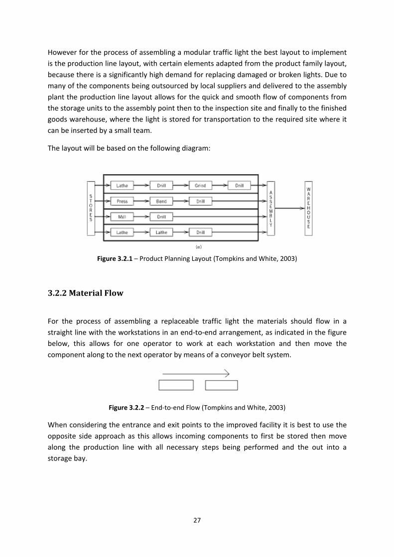
However for the process of assembling a modular traffic light the best layout to implement
is the production line layout, with certain elements adapted from the product family layout,
because there is a significantly high demand for replacing damaged or broken lights. Due to
many of the components being outsourced by local suppliers and delivered to the assembly
plant the production line layout allows for the quick and smooth flow of components from
the storage units to the assembly point then to the inspection site and finally to the finished
goods warehouse, where the light is stored for transportation to the required site where it
can be inserted by a small team.
The layout will be based on the following diagram:
Figure 3.2.1 – Product Planning Layout (Tompkins and White, 2003)
3.2.2 Material Flow
For the process of assembling a replaceable traffic light the materials should flow in a
straight line with the workstations in an end-to-end arrangement, as indicated in the figure
below, this allows for one operator to work at each workstation and then move the
component along to the next operator by means of a conveyor belt system.
Figure 3.2.2 – End-to-end Flow (Tompkins and White, 2003)
When considering the entrance and exit points to the improved facility it is best to use the
opposite side approach as this allows incoming components to first be stored then move
along the production line with all necessary steps being performed and the out into a
storage bay.
28
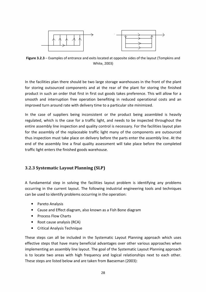
Figure 3.2.3 – Examples of entrance and exits located at opposite sides of the layout (Tompkins and
White, 2003)
In the facilities plan there should be two large storage warehouses in the front of the plant
for storing outsourced components and at the rear of the plant for storing the finished
product in such an order that first in first out goods takes preference. This will allow for a
smooth and interruption free operation benefiting in reduced operational costs and an
improved turn around rate with delivery time to a particular site minimized.
In the case of suppliers being inconsistent or the product being assembled is heavily
regulated, which is the case for a traffic light, and needs to be inspected throughout the
entire assembly line inspection and quality control is necessary. For the facilities layout plan
for the assembly of the replaceable traffic light many of the components are outsourced
thus inspection must take place on delivery before the parts enter the assembly line. At the
end of the assembly line a final quality assessment will take place before the completed
traffic light enters the finished goods warehouse.
3.2.3 Systematic Layout Planning (SLP)
A fundamental step in solving the facilities layout problem is identifying any problems
occurring in the current layout. The following industrial engineering tools and techniques
can be used to identify problems occurring in the operation:
• Pareto Analysis
• Cause and Effect diagram, also known as a Fish Bone diagram
• Process Flow Charts
• Root cause analysis (RCA)
• Critical Analysis Technique
These steps can all be included in the Systematic Layout Planning approach which uses
effective steps that have many beneficial advantages over other various approaches when
implementing an assembly line layout. The goal of the Systematic Layout Planning approach
is to locate two areas with high frequency and logical relationships next to each other.
These steps are listed below and are taken from Baeseman (2003):
29
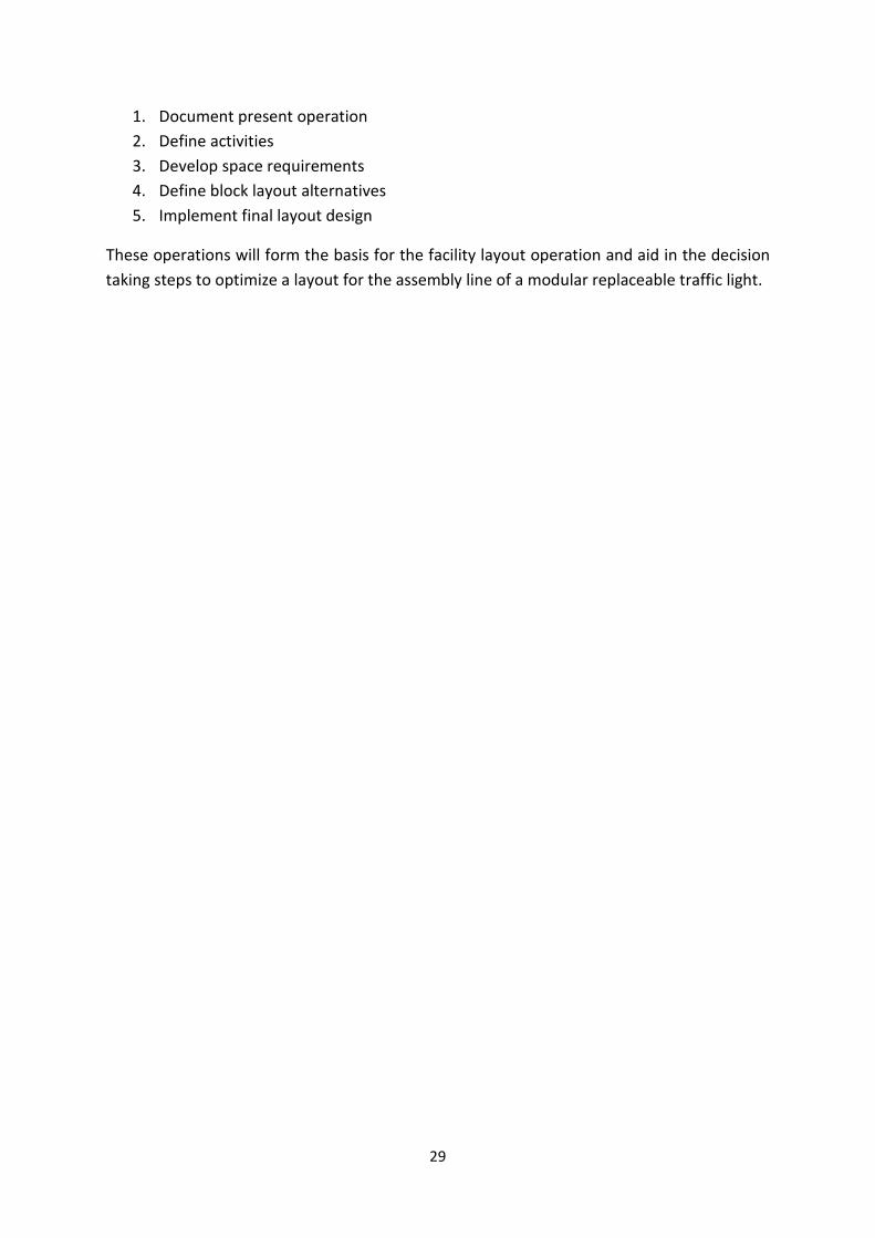
1. Document present operation
2. Define activities
3. Develop space requirements
4. Define block layout alternatives
5. Implement final layout design
These operations will form the basis for the facility layout operation and aid in the decision
taking steps to optimize a layout for the assembly line of a modular replaceable traffic light.
30
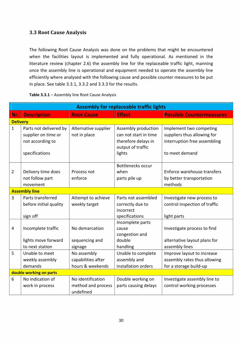
3.3 Root Cause Analysis
The following Root Cause Analysis was done on the problems that might be encountered
when the facilities layout is implemented and fully operational. As mentioned in the
literature review (chapter 2.6) the assembly line for the replaceable traffic light, manning
once the assembly line is operational and equipment needed to operate the assembly line
efficiently where analysed with the following cause and possible counter measures to be put
in place. See table 3.3.1, 3.3.2 and 3.3.3 for the results.
Table 3.3.1 – Assembly line Root Cause Analysis
Assembly for replaceable traffic lights
Nr. Description Root Cause Effect Possible Countermeasures
Delivery
1 Parts not delivered by Alternative supplier Assembly production Implement two competing
supplier on time or not in place can not start in time suppliers thus allowing for
not according to therefore delays in interruption free assembling
specifications
output of traffic
lights to meet demand
2 Delivery time does Process not
Bottlenecks occur
when Enforce warehouse transfers
not follow part enforce parts pile up by better transportation
movement methods
Assembly line
3 Parts transferred Attempt to achieve Parts not assembled Investigate new process to
before initial quality weekly target correctly due to control inspection of traffic
sign off
incorrect
specifications light parts
4 Incomplete traffic No demarcation
Incomplete parts
cause Investigate process to find
lights move forward sequencing and
congestion and
double alternative layout plans for
to next station signage handling assembly lines
5 Unable to meet No assembly Unable to complete Improve layout to increase
weekly assembly capabilities after assembly and assembly rates thus allowing
demands hours & weekends installation orders for a storage build-up
double working on parts
6 No indication of No identification Double working on Investigate assembly line to
work in process method and process parts causing delays control working processes
undefined
31
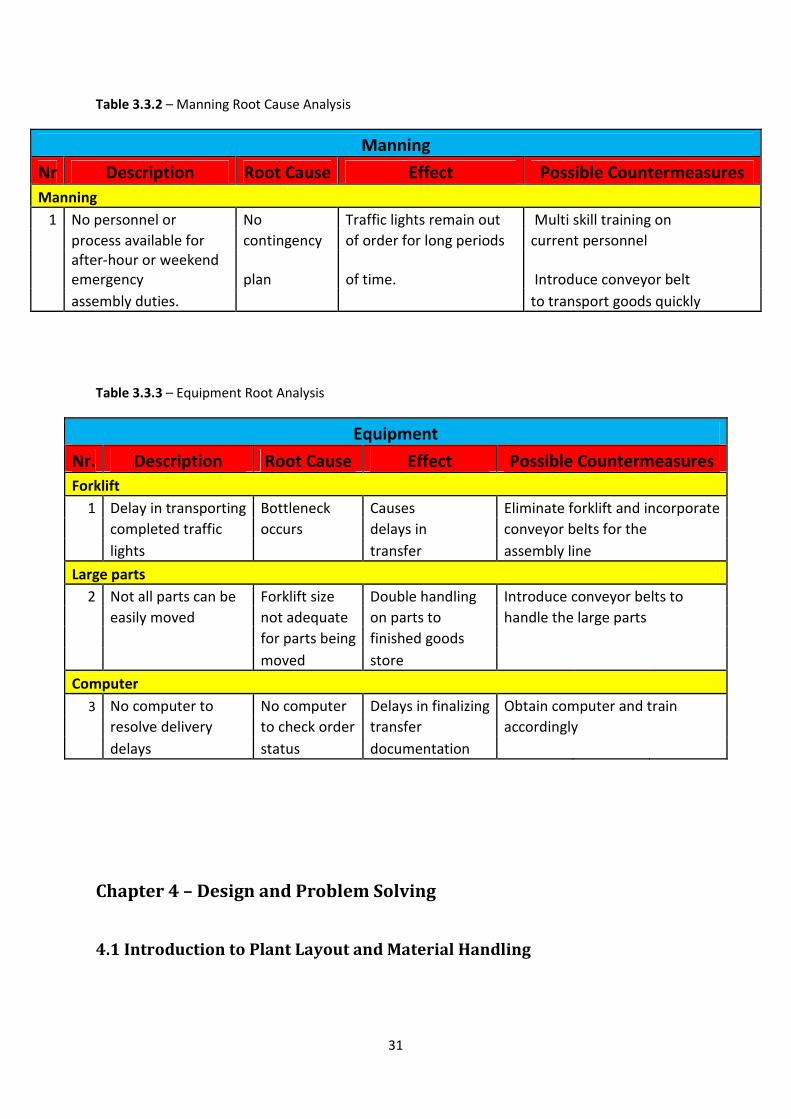
Table 3.3.2 – Manning Root Cause Analysis
Manning
Nr Description Root Cause Effect Possible Countermeasures
Manning
1 No personnel or No Traffic lights remain out Multi skill training on
process available for contingency of order for long periods current personnel
after-hour or weekend
emergency plan of time. Introduce conveyor belt
assembly duties. to transport goods quickly
Table 3.3.3 – Equipment Root Analysis
Equipment
Nr. Description Root Cause Effect Possible Countermeasures
Forklift
1 Delay in transporting Bottleneck Causes Eliminate forklift and incorporate
completed traffic occurs delays in conveyor belts for the
lights transfer assembly line
Large parts
2 Not all parts can be Forklift size Double handling Introduce conveyor belts to
easily moved not adequate on parts to handle the large parts
for parts being finished goods
moved store
Computer
3 No computer to No computer Delays in finalizing Obtain computer and train
resolve delivery to check order transfer accordingly
delays status documentation
Chapter 4 – Design and Problem Solving
4.1 Introduction to Plant Layout and Material Handling
32
Facilities layout planning uses the company’s physical facilities to promote the efficient use
of equipment, material, people and energy. Plant layout is a division of the entire facilities
design project. Facilities design incorporates plant location, building design, placement of
departments, work groups, allocation of workstations and material handling. (Meyers. E,
1993:1).
The objective of the plant layout is to optimize and smooth the work flow of materials,
machines and equipment throughout the assembly of the replaceable traffic light. This
being a new design (as previously mentioned), the focus will be placed on the plant layout,
material flow and material handling.
Material handling is defined as moving material throughout a system. Fred E. Meyers
(1993:2) states that “…if you improve the flow of material, you will automatically reduce
production costs. The shorter the flow throughout the plant, the better” (Meyers. E,
1993:2).
Plant layout is dependent on material handling and thus it is important to make the correct
choices when considering material handling equipment and the allocation of these parts in
the system. We must never forget that material handling and plant layout are inseparable in
the real world. (Meyers. E, 1993:2).
The mission statement for this plant is to design a feasible yet functional assembly line in
order to reduce the time taken to deliver and replace a damaged traffic light. By finding an
optimal material flow and assembly line pattern the current costs incurred for replacing
damaged traffic lights can be reduced.
The following goals were of main importance:
• Increasing throughput
• Reducing material costs
• Safe working environment (ergonomics)
• First in, first out.
The most visible waste is not scrap but good materials sitting idle. – George W. Plossl
4.2 Flow Patterns
33
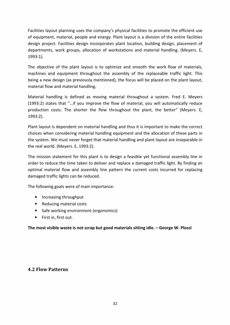
There are a number of flow patterns to be considered when developing a facility layout
design as this is an important aspect of the entire system as it dictates the assembly rate.
The two primary layouts for an assembly of a replaceable traffic light are shown below:
Figure 4.2.1 – Various flow patterns in as assembly line
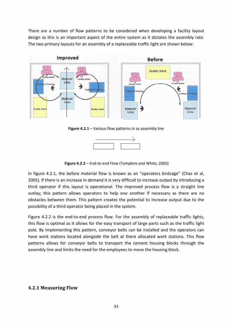
Figure 4.2.2 – End-to-end Flow (Tompkins and White, 2003)
In figure 4.2.1, the before material flow is known as an “operators birdcage” (Chas et al,
2005). If there is an increase in demand it is very difficult to increase output by introducing a
third operator if this layout is operational. The improved process flow is a straight line
outlay; this pattern allows operators to help one another if necessary as there are no
obstacles between them. This pattern creates the potential to increase output due to the
possibility of a third operator being placed in the system.
Figure 4.2.2 is the end-to-end process flow. For the assembly of replaceable traffic lights,
this flow is optimal as it allows for the easy transport of large parts such as the traffic light
pole. By implementing this pattern, conveyor belts can be installed and the operators can
have work stations located alongside the belt at there allocated work stations. This flow
patterns allows for conveyor belts to transport the cement housing blocks through the
assembly line and limits the need for the employees to move the housing block.
4.2.1 Measuring Flow
34
As the entire assembly line operation is dependant on the flow of material among the work
stations it is one of the most critical factors in designing and arranging the plant layout.
Material flow among the stations needs to be measured. These measurements can be done
in a quantitative and qualitative manner. Quantitative measures may include the
measurement of material, information and people between stations by pieces per hour,
moves per day or units per week. Qualitative measures focuses on the intangible factors
that need to be considered between two stations, these include, communication, noise, cost
and pollution. Stations that have significant communications and organizational
interrelations but have little material or people influence should be considered as
qualitative candidates and must be placed towards the end of the assembly line as they do
not control the rate of assembly.
It is essential that both qualitative and quantitative measures of flow should be used to
achieve an optimal solution for the design of a facilities plant layout.
The following techniques were incorporated as part of Murther’s Systematic Layout
Planning approach to determine the optimal process flow and layout design for the new
plant layout for the assembling of replaceable modular traffic lights.
4.2.1.1 Quantitative flow measurements
The amounts of units of flow between work stations and through the assembly line are
measured quantitatively. A “From-to-chart” is used to record these flows. This tool indicates
the material flow relationships for the assembly line of the traffic light.
The From-to-chart is constructed as follows for the necessary stations needed to assembly a
replaceable traffic light according to Murther’s Systematic Layout Planning Procedure
(Tompkins et al, 2003):
1. All the stations needed to complete the assembly of the replaceable traffic light are
listed down and across the columns. These stations follow in order from initial
delivery to final storage of completed parts.
2. The units that flow between stations are recorded in the From-to-chart. The From-
to-chart represents the relationship of flow of units between stations.
The process for the assembly line is as follows:
35
• The outsourced products or materials arrive at the delivery bay by the suppliers.
• The material is then transported by forklift to the initial storage area and stored in
designated departments.
• The components are split into the necessary parts for the three conveyor belts, line 1
and 2 assembly the same parts (light pole with attachments) and line 3 assembles
the housing block and base plate.
• The replaceable traffic light is assembled at the specific workstations along the
conveyor belt, socket station, bracket station, light box station and finally the
electricity supply station.
• If the assembled traffic light needs painting it moves along to the paint booth.
• Once the traffic light is assembled it is transported by forklift to the inspection room
where final checks and testing takes place.
• The completed replaceable traffic light is stored in the finished goods department,
ready for dispatch following the first in first out process.
• Finally the traffic light with housing block is loaded onto the installation truck for
dispatch to the required site.
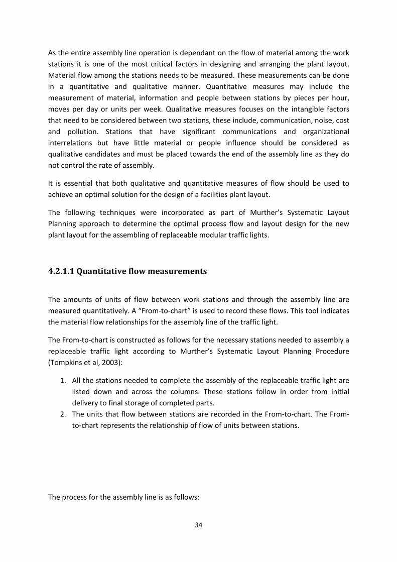
S Room: Initial Storage and Inspection Room
SS: Socket Installation Station
SB: Bracket Station
SL: Light Box Fitting Station
SE: Electrical Supply Station
Paint: Paint Booth
I Room: Inspection Room
FS Room: Finished Goods Storage Room
Out: Out of System
Table 4.2.1 – Key code for stations in sequence they appear to complete assembly of replaceable
traffic light
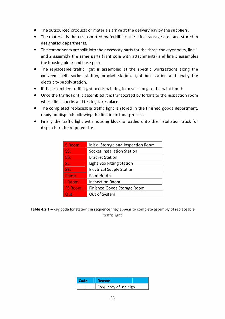
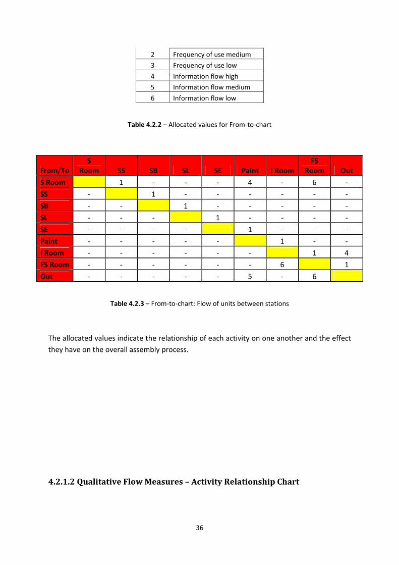
Code Reason
1 Frequency of use high
36
2 Frequency of use medium
3 Frequency of use low
4 Information flow high
5 Information flow medium
6 Information flow low
Table 4.2.2 – Allocated values for From-to-chart
From/To
S
Room SS SB SL SE Paint I Room
FS
Room Out
S Room 1 - - - 4 - 6 -
SS - 1 - - - - - -
SB - - 1 - - - - -
SL - - - 1 - - - -
SE - - - - 1 - - -
Paint - - - - - 1 - -
I Room - - - - - - 1 4
FS Room - - - - - - 6 1
Out - - - - - 5 - 6
Table 4.2.3 – From-to-chart: Flow of units between stations
The allocated values indicate the relationship of each activity on one another and the effect
they have on the overall assembly process.
4.2.1.2 Qualitative Flow Measures – Activity Relationship Chart
37
To measure the qualitative flow, closeness relationship values must be determined by
implementing Murther’s strategy. This step in the designing of a facility layout is adjusted to
fit the requirements of assembling a traffic light. A relationship chart is constructed for the
assembly line by using these values. A relationship chart may be constructed as follows
(Tompkins et al, 2003):
1. List all the assembly line stations on the relationship diagram.
2. Once the assembly line and facilities plan is operational, conduct interviews with
employees from each station and management overseeing the assembly of the
traffic light to see where improvements can be made.
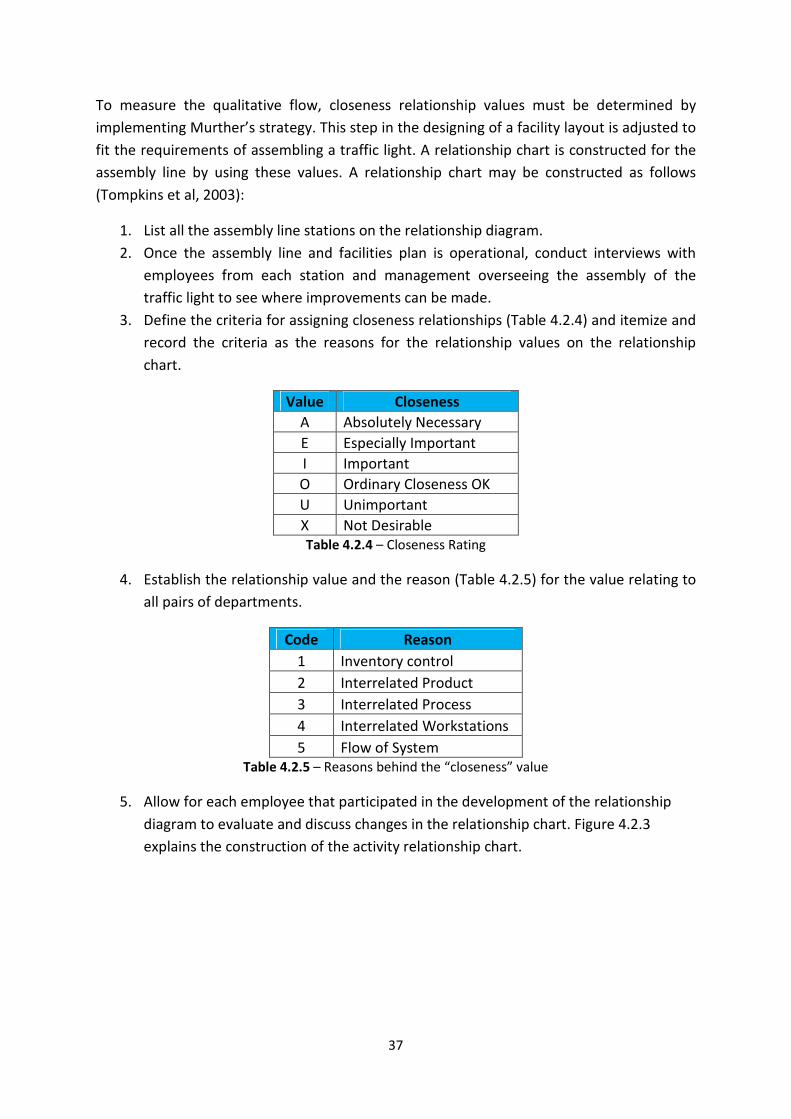
3. Define the criteria for assigning closeness relationships (Table 4.2.4) and itemize and
record the criteria as the reasons for the relationship values on the relationship
chart.
Value Closeness
A Absolutely Necessary
E Especially Important
I Important
O Ordinary Closeness OK
U Unimportant
X Not Desirable
Table 4.2.4 – Closeness Rating
4. Establish the relationship value and the reason (Table 4.2.5) for the value relating to
all pairs of departments.
Code Reason
1 Inventory control
2 Interrelated Product
3 Interrelated Process
4 Interrelated Workstations
5 Flow of System
Table 4.2.5 – Reasons behind the “closeness” value
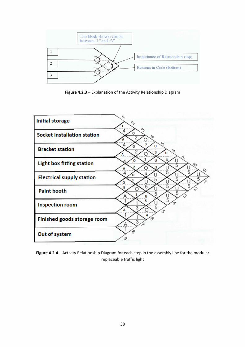
5. Allow for each employee that participated in the development of the relationship
diagram to evaluate and discuss changes in the relationship chart. Figure 4.2.3
explains the construction of the activity relationship chart.
38
Figure 4.2.3 – Explanation of the Activity Relationship Diagram
Figure 4.2.4 – Activity Relationship Diagram for each step in the assembly line for the modular
replaceable traffic light
39
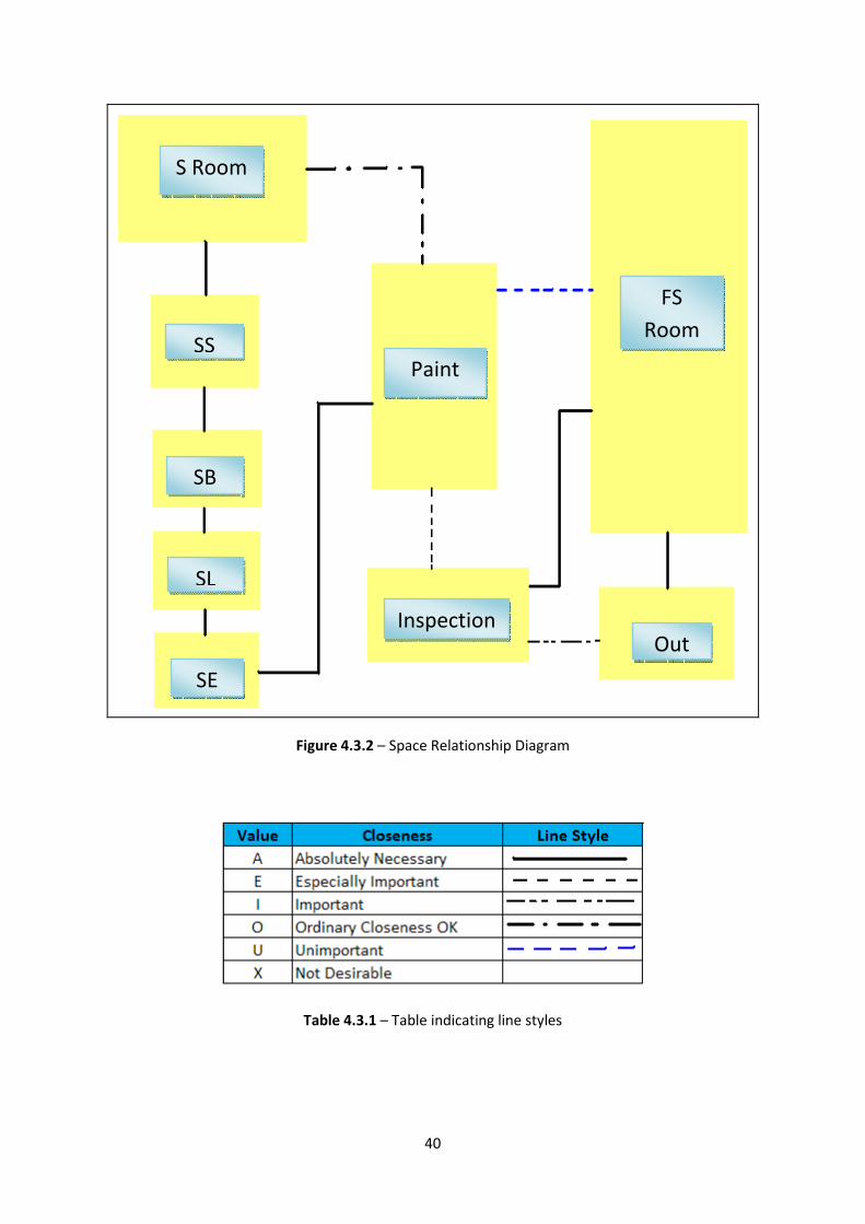
4.3 Space Relationship Diagram
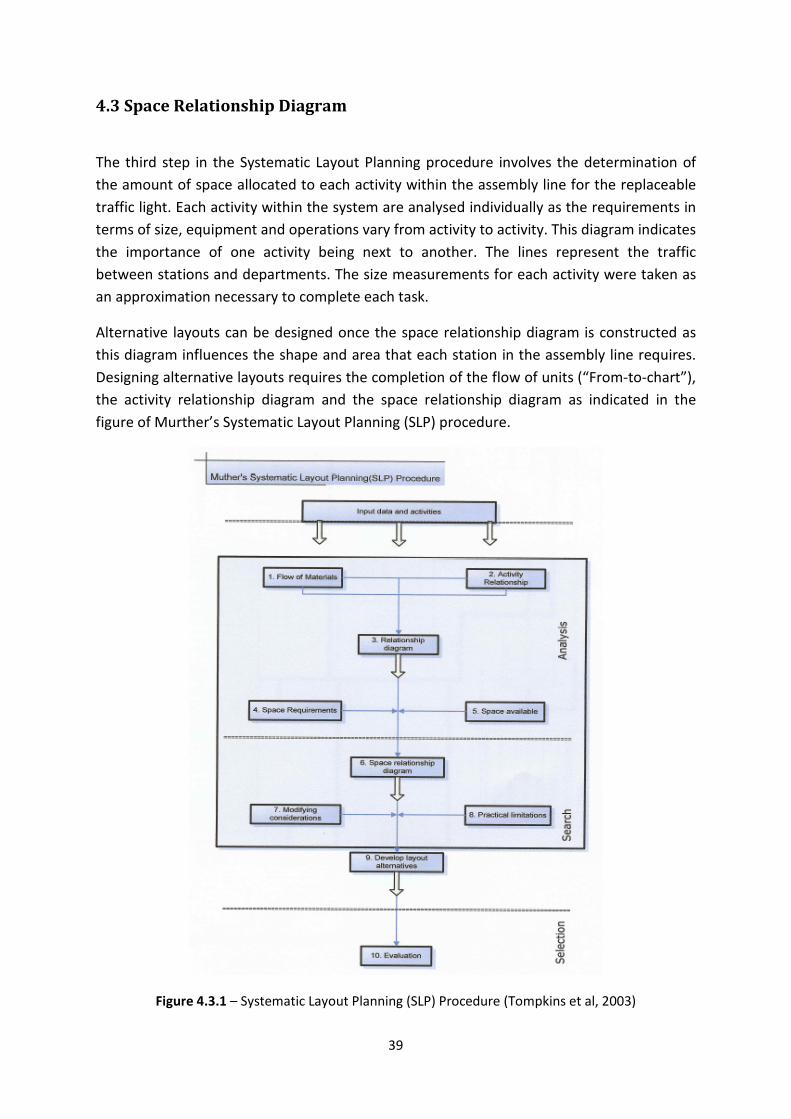
The third step in the Systematic Layout Planning procedure involves the determination of
the amount of space allocated to each activity within the assembly line for the replaceable
traffic light. Each activity within the system are analysed individually as the requirements in
terms of size, equipment and operations vary from activity to activity. This diagram indicates
the importance of one activity being next to another. The lines represent the traffic
between stations and departments. The size measurements for each activity were taken as
an approximation necessary to complete each task.
Alternative layouts can be designed once the space relationship diagram is constructed as
this diagram influences the shape and area that each station in the assembly line requires.
Designing alternative layouts requires the completion of the flow of units (“From-to-chart”),
the activity relationship diagram and the space relationship diagram as indicated in the
figure of Murther’s Systematic Layout Planning (SLP) procedure.
Figure 4.3.1 – Systematic Layout Planning (SLP) Procedure (Tompkins et al, 2003)
40
Figure 4.3.2 – Space Relationship Diagram
Table 4.3.1 – Table indicating line styles
S Room
SB
SL
SE
Inspection
Paint
FS
Room
Out
SS
41
4.4 Develop Layout Alternatives
Two alternative facility layout plans have been designed for the assembly line. The layouts
to assemble a replaceable traffic light to fulfill demand and meet the correct specifications
needed for the modern day traffic light can be seen in Appendix B.
4.5 Evaluate Alternative Facility Layout Designs
Two alternative facilities layouts have been designed so that a comparison can be made and
the best layout can be implemented to assembly the replaceable traffic light with the most
efficient output. These layouts were designed and analysed based on Murther’s Systematic
Layout Planning procedure. Murther’s approach locates two stations with high frequency
and their interlinked relationship close to one another. By implementing and adapting the
steps obtained from Murther’s procedure an optimal facility layout can be identified that
will provide a smooth and efficient assembly line for the traffic light.
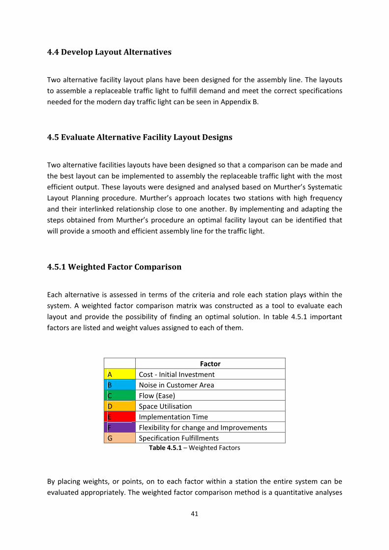
4.5.1 Weighted Factor Comparison
Each alternative is assessed in terms of the criteria and role each station plays within the
system. A weighted factor comparison matrix was constructed as a tool to evaluate each
layout and provide the possibility of finding an optimal solution. In table 4.5.1 important
factors are listed and weight values assigned to each of them.
Factor
A Cost - Initial Investment
B Noise in Customer Area
C Flow (Ease)
D Space Utilisation
E Implementation Time
F Flexibility for change and Improvements
G Specification Fulfillments
Table 4.5.1 – Weighted Factors
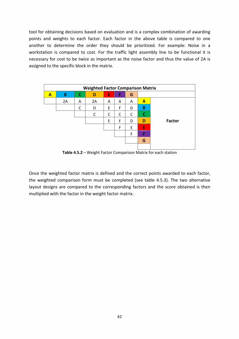
By placing weights, or points, on to each factor within a station the entire system can be
evaluated appropriately. The weighted factor comparison method is a quantitative analyses
42
tool for obtaining decisions based on evaluation and is a complex combination of awarding
points and weights to each factor. Each factor in the above table is compared to one
another to determine the order they should be prioritized. For example: Noise in a
workstation is compared to cost. For the traffic light assembly line to be functional it is
necessary for cost to be twice as important as the noise factor and thus the value of 2A is
assigned to the specific block in the matrix.
Weighted Factor Comparison Matrix
A B C D E F G
2A A 2A A A A A
C D E F G B
C C C C C
E F D D Factor
F E E
F F
G
Table 4.5.2 – Weight Factor Comparison Matrix for each station
Once the weighted factor matrix is defined and the correct points awarded to each factor,
the weighted comparison form must be completed (see table 4.5.3). The two alternative
layout designs are compared to the corresponding factors and the score obtained is then
multiplied with the factor in the weight factor matrix.
43
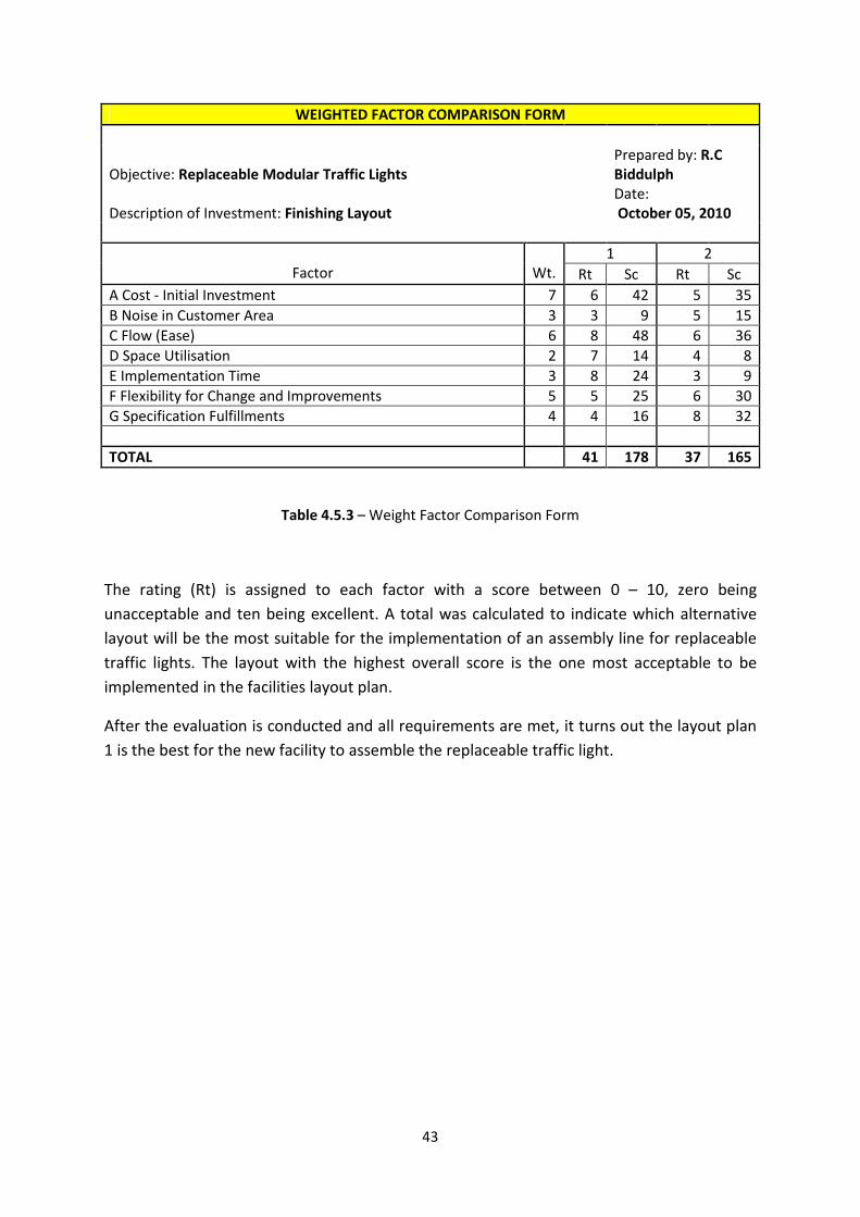
WEIGHTED FACTOR COMPARISON FORM
Objective: Replaceable Modular Traffic Lights
Prepared by: R.C
Biddulph
Description of Investment: Finishing Layout
Date:
October 05, 2010
1 2
Factor Wt. Rt Sc Rt Sc
A Cost - Initial Investment 7 6 42 5 35
B Noise in Customer Area 3 3 9 5 15
C Flow (Ease) 6 8 48 6 36
D Space Utilisation 2 7 14 4 8
E Implementation Time 3 8 24 3 9
F Flexibility for Change and Improvements 5 5 25 6 30
G Specification Fulfillments 4 4 16 8 32
TOTAL 41 178 37 165
Table 4.5.3 – Weight Factor Comparison Form
The rating (Rt) is assigned to each factor with a score between 0 – 10, zero being
unacceptable and ten being excellent. A total was calculated to indicate which alternative
layout will be the most suitable for the implementation of an assembly line for replaceable
traffic lights. The layout with the highest overall score is the one most acceptable to be
implemented in the facilities layout plan.
After the evaluation is conducted and all requirements are met, it turns out the layout plan
1 is the best for the new facility to assemble the replaceable traffic light.
44
4.6 Material Handling
Material handling is the process of moving the correct material to the correct place, at the
right time, in the required amount, in sequence, and in allocating it to the correct position
or having it in the required specifications to minimize production costs. Material handling
involves the handling of equipment, storage facilities, and the controlling methods, (Fred E.
Meyers, 1993:157)
Material handling is an important component in facilities design as they are interlinked. A
change in the material handling system will change the layout, and a layout alteration will
change the material handling process. In a typical industrial facility, material handling
accounts for 25% of all employees, 55% of all factory space, and 87% of production time,
(Franzelle, 1986).
In assembly line for the replaceable traffic lights, project material is moved by hand and by
automated methods. Each component will have a fixed path and location that it will travel
to. A forklift will transport the components from the storage facilities to the conveyor belts
where work will be done on them by hand and then transported to the finished goods
storage by forklift. By introducing the JIT process emphasis will be placed on pulling the
material rather than pushing the components through the assembly line, thus reducing
queues and work in process.
By following the operation analyses for material handling (Figure 2.6.1) the correct flow can
be determined and helps identify opportunities in the facility layout design for
improvements. The new assembly line must be able to:
• Be user friendly
• Increase flexibility
• Increase efficiency of material flow
• Increase productivity
• Reduce material handling costs
• Improve facility utilization
• Reduce assembly time
These following steps indicate the movement of material through the assembly line and the
order of stations required to complete the process and ultimately result in an efficient and
cost effective assembly line for the traffic lights, (A diagram will be constructed to illustrate
the procedure):
Step 1: Delivery trucks from suppliers deliver the outsourced parts to the docks and are
transported by forklift to the initial storage warehouse where an inspection takes place.
45
Step 2: Once the components are ready to be assembled forklifts transport the parts to one
of three conveyor belts, which will pull the components through each workstation so the
traffic light can be assembled.
Step 3: The traffic light is assembled at each specific work station, with a testing station at
the end to make sure the replaceable traffic light is operational.
Step 4: On completion of the assembled traffic light it will move to a paint booth for final
painting, making it ready for installation according to the required specifications and
regulations.
Step 5: From the paint both a forklift will transport the finished component to the final
storage and inspection warehouse, awaiting final delivery to the necessary site.
46
Chapter 5 – Budget
With reference to the new design and building of the assembly facility for the replaceable
traffic light (as indicated in Appendix A), finances will be accessed and acquired to construct
the facilities layout in order to fulfill all demand requirements and achieve a smooth running
assembly plant. All the necessary equipment and tools required to assembly the traffic light
have been budgeted for and will be bought to fulfill the required demand.
An amount of R 11 million will be needed to construct the necessary facilities plant and to
purchase all the tools and material handling equipment.
The funds needed to develop this project will be a large short term investment but the long
term investment will be reduced as the initial cost for installation will be high but the
replacement costs for the necessary parts that need to be replaced will be low as they make
up the smaller parts of the replaceable traffic light.
47
Chapter 6 – Recommendations and Conclusion
6.1 Recommendations
When deciding on the correct facilities layout it tends to follow the satisfactory process
rather than the optimizing process. With this in mind further testing and validation can take
place to determine which layout fulfills all the necessary requirements needed to meet the
modern day demand placed on replacing damaged or out of order traffic lights. There are a
number of testing processes that can be performed namely, excel spreadsheets to
determine economic factors, simulation modeling to determine where improvements and
backlogs are located and Facilities Layout Applet/Application program (FLAP) heuristics
which achieves the lowest cost and travel between stations thus ensuring one layout is
better then another.
Many other departments and factors can be investigated once the finding in this report
have been implemented such as: expansion in the assembly plant to accommodate future
growth, parking and exterior environments, an in-depth look at the outsourced suppliers
and whether it is more prosperous to incorporate in-house development, and most
importantly if the entire assembly system should become automated which will ultimately
result in a much higher output and greater accuracy in the finished product.
6.2 Conclusion
Facilities planning, when implemented correctly, will result in a number of advantages over
a standard layout structure. A correctly laid out assembly line will benefit from an increased
return on assets, improved customer satisfaction resulting in a larger demand for the
product, reduced costs in the region of transporting the goods, storage, an integrated
supply chain focusing on the ultimate customer and inventory carrying costs.
The analysis of facilities design such as layout and material handling is very important to
optimize an assembly line. Many improvements can result from an optimized facilities
layout plan, such as a decrease in bottleneck rates, minimize operational costs, reduce idle
times throughout the assembly, and raise the production rate effectively increasing profit.
With such a large demand on today’s manufacturing and assembly lines it is critical to have
an uninterrupted flow through a plant, thus optimal facility planning is necessary in order to
stay ahead of the competition.
This project has provided an insight to the necessary requirements needed to implement a
feasible solution for the assembly of replaceable traffic lights. This project focuses on three
48
phases, facility layout planning, material handling and material flow throughout the
assembly line. However this is only a small part of facilities design but is done in order to
show how industrial engineering tools can be implemented and the problem can be
approached from various angles in order to produce a feasible solution.
Facilities layout design and correct material handling techniques are the fundamental
starting points for an assembly project as they are interlinked and determine the size of the
facility that is needed to run an efficient system.
The replaceable traffic light is a new design that strives to improve the current situation of
replacing damaged lights that take extended time periods to fix or replace. Using new
materials and procedures the replaceable traffic light can make large inroads into improving
the overall road safety and reducing delays in traffic congestion for all South Africans.
The goal of this project is to find a new facility layout for the assembly of replaceable traffic
lights in order to reduce replacing time for damaged traffic lights on street corners. The
facility will be designed to accommodate future forecasted growth, expansion for assembly
and the flexibility to change according to the required specifications put forward by the
traffic department.
49
List of References
• Baeseman, J. (2003). Facilities Planning Methodology. Bodi Engineering LLC.
• Chase, R.B. and Jacobs, F.R. (2006). Operations Management for Competitive
Advantage with Global Cases. McGraw-Hill, 11th
edition.
• Coyle, J.J. and Bardi, E.J. (2003). The Management of Business Logistics: A Supply
Chain Perspective. South-Western – Thomson Learning, 7th
edition.
• Dwijayanti, K. and Aoyama, H. (2010). A Proposed Study on Facilities Planning and
Design in Manufacturing Process. ISSN: 2078-0958. Hong Kong.
• Geer, B. (2005). Traffic Light with Modular Pole. Patent WO/2005/057520.
www.wipo.int/pctdb/en/wo.jsp
• Greasly, A. (2008). Using Simulation for Facility Design: A case study. Elsevier
International journal of Simulation Modelling Practice and Theory 16. Pages 670-677.
• Haung, H. (2003). Facility Layout using Layout Models. Ph.D. Thesis. The Ohio State
University.
• Kuhl, M.E. and Streiger, N.M. and Armstrong, F.B. and Joines, J.A. (2005). For
effective facilities planning Layout Optimization then simulation or visa versa.
Proceedings of the 2005 Winter Simulation Conference, University at Buffalo.
• Kulmiec, R.A. (1985). Materials Handling Handbook. John Wiley and Sons, the
American Society of Mechanical Engineers and the International Material
Management Society, USA. 2nd
edition.
• LIGHTS TO GO! http://www.trafficlights.com/LEDsigs.htm
• Madumo, L. (2008). Futuristic Traffic Light System for Jozi.
http://www.joburg.org.za/content/view/2034/168
• Muther, R. (1961). Systematic Layout Planning. McGraw-Hill, New York.
• Reid, R.D. and Sanders, N.R. (2007). Operations Management. John Wiley and Sons.
New York. 3rd
edition.
• Sule, D.R. (1994). Manufacturing Facilities: Location, Planning, and Design. PWSKent
Publishing Company, 2nd
edition.
• Tompkins, J.A. and White, J.A. (2003). Facilities Planning. John Wiley and Sons, INC,
3rd
edition.
• TransAmerican Power Products, Inc. TR Series. www.tappinc.com

50
Appendices
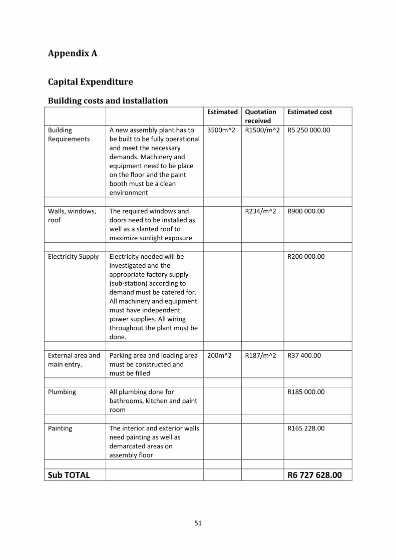
51
Appendix A
Capital Expenditure
Building costs and installation
Estimated Quotation
received
Estimated cost
Building
Requirements
A new assembly plant has to
be built to be fully operational
and meet the necessary
demands. Machinery and
equipment need to be place
on the floor and the paint
booth must be a clean
environment
3500m^2 R1500/m^2 R5 250 000.00
Walls, windows,
roof
The required windows and
doors need to be installed as
well as a slanted roof to
maximize sunlight exposure
R234/m^2 R900 000.00
Electricity Supply Electricity needed will be
investigated and the
appropriate factory supply
(sub-station) according to
demand must be catered for.
All machinery and equipment
must have independent
power supplies. All wiring
throughout the plant must be
done.
R200 000.00
External area and
main entry.
Parking area and loading area
must be constructed and
must be filled
200m^2 R187/m^2 R37 400.00
Plumbing All plumbing done for
bathrooms, kitchen and paint
room
R185 000.00
Painting The interior and exterior walls
need painting as well as
demarcated areas on
assembly floor
R165 228.00
Sub TOTAL R6 727 628.00
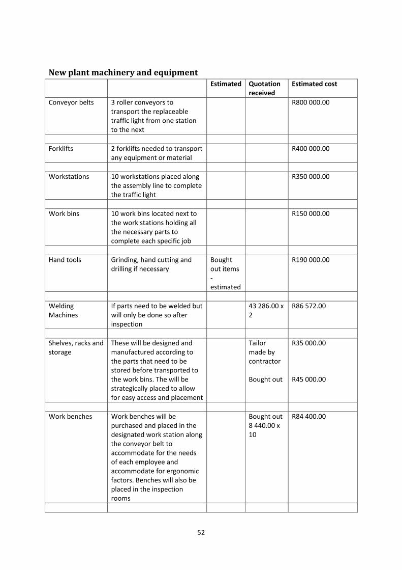
52
New plant machinery and equipment
Estimated Quotation
received
Estimated cost
Conveyor belts 3 roller conveyors to
transport the replaceable
traffic light from one station
to the next
R800 000.00
Forklifts 2 forklifts needed to transport
any equipment or material
R400 000.00
Workstations 10 workstations placed along
the assembly line to complete
the traffic light
R350 000.00
Work bins 10 work bins located next to
the work stations holding all
the necessary parts to
complete each specific job
R150 000.00
Hand tools Grinding, hand cutting and
drilling if necessary
Bought
out items
-
estimated
R190 000.00
Welding
Machines
If parts need to be welded but
will only be done so after
inspection
43 286.00 x
2
R86 572.00
Shelves, racks and
storage
These will be designed and
manufactured according to
the parts that need to be
stored before transported to
the work bins. The will be
strategically placed to allow
for easy access and placement
Tailor
made by
contractor
Bought out
R35 000.00
R45 000.00
Work benches Work benches will be
purchased and placed in the
designated work station along
the conveyor belt to
accommodate for the needs
of each employee and
accommodate for ergonomic
factors. Benches will also be
placed in the inspection
rooms
Bought out
8 440.00 x
10
R84 400.00
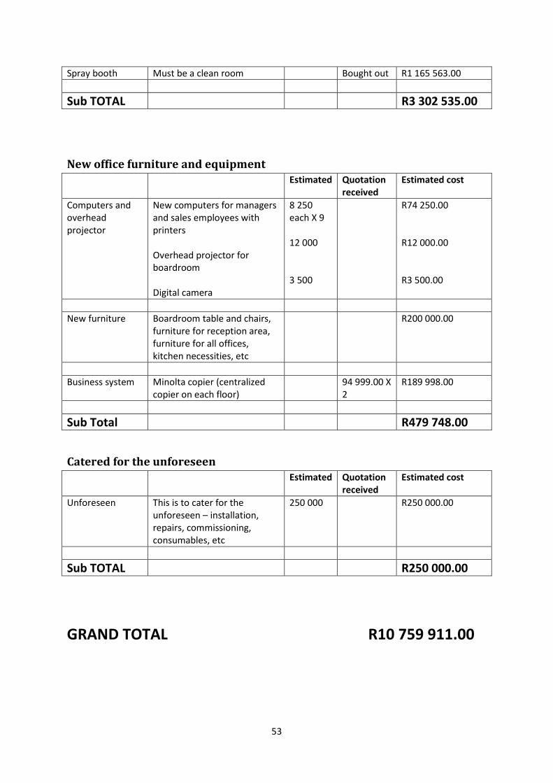
53
Spray booth Must be a clean room Bought out R1 165 563.00
Sub TOTAL R3 302 535.00
New office furniture and equipment
Estimated Quotation
received
Estimated cost
Computers and
overhead
projector
New computers for managers
and sales employees with
printers
Overhead projector for
boardroom
Digital camera
8 250
each X 9
12 000
3 500
R74 250.00
R12 000.00
R3 500.00
New furniture Boardroom table and chairs,
furniture for reception area,
furniture for all offices,
kitchen necessities, etc
R200 000.00
Business system Minolta copier (centralized
copier on each floor)
94 999.00 X
2
R189 998.00
Sub Total R479 748.00
Catered for the unforeseen
Estimated Quotation
received
Estimated cost
Unforeseen This is to cater for the
unforeseen – installation,
repairs, commissioning,
consumables, etc
250 000 R250 000.00
Sub TOTAL R250 000.00
GRAND TOTAL R10 759 911.00
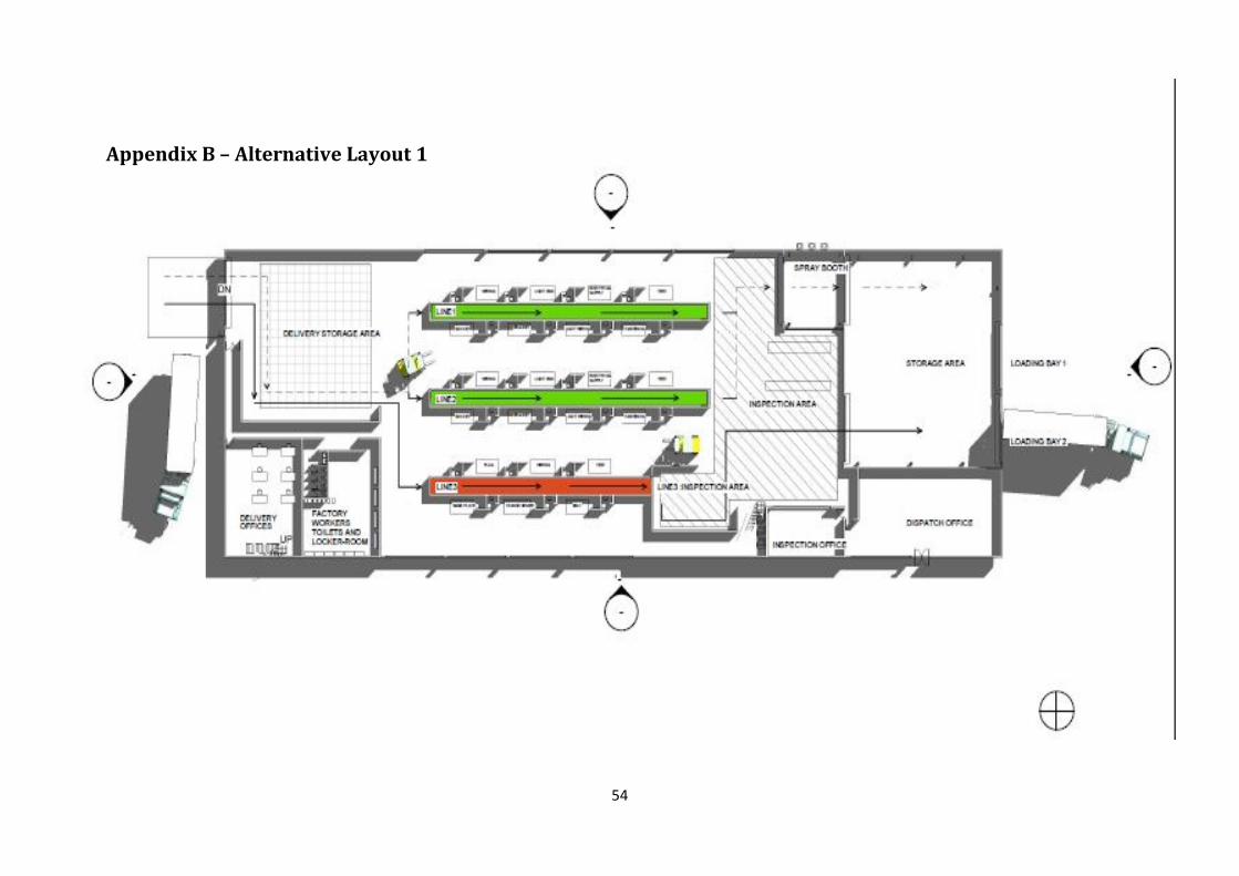
54
Appendix B – Alternative Layout 1
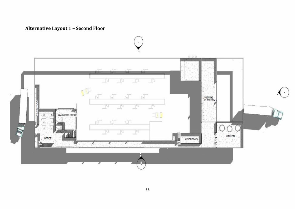
55
Alternative Layout 1 – Second Floor
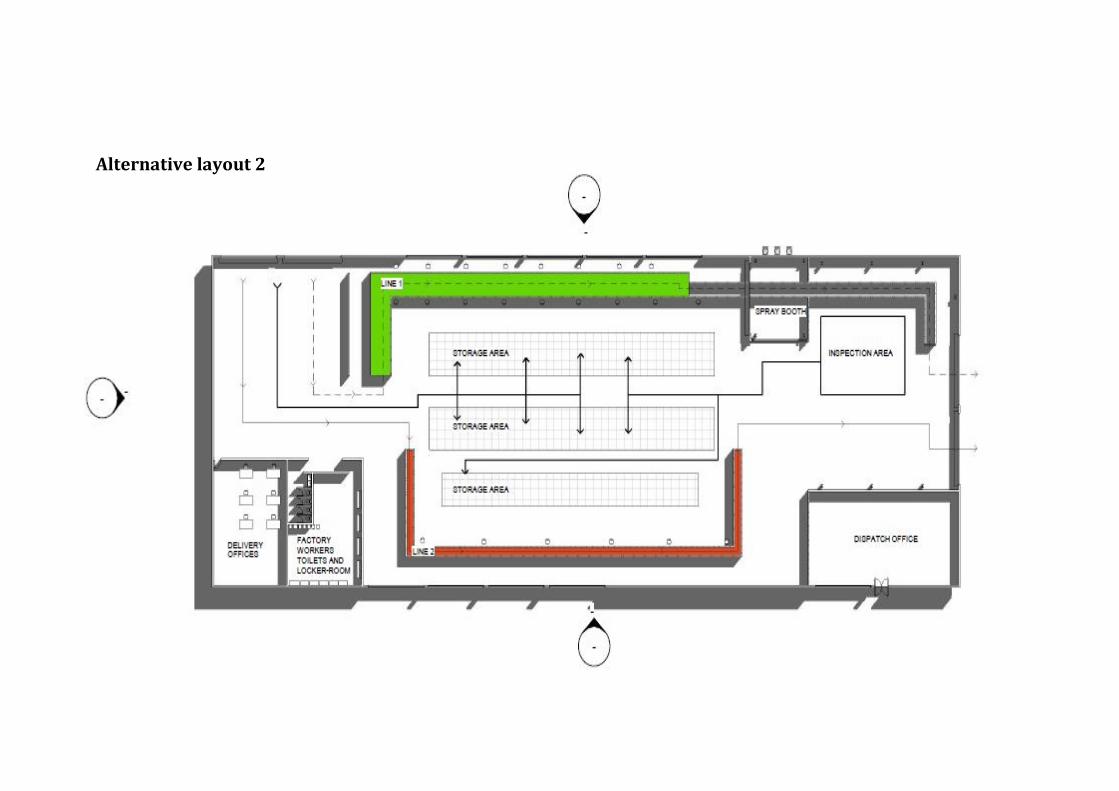
56
Alternative layout 2
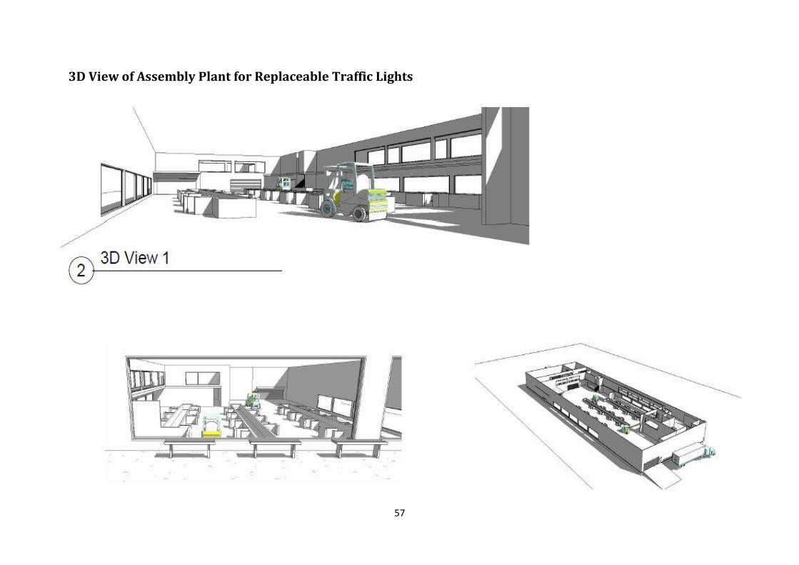
57
3D View of Assembly Plant for Replaceable Traffic Lights