Lecture(7) Layout for manufacturing facilities 2-additional objectives for Warehouse operation...
26
Lecture(7) Layout for manufacturing facilities facility layout means planning for the location of all machines, utilities, employee workstations, customer service areas, material storage areas, aisles, rest rooms, lunchrooms, drinking fountains, internal walls, offices, and computer rooms, and for the flow patterns of materials and people around, into, and within buildings. Through facility layouts, the physical arrangement of these processes within and around buildings, the space necessary for the operation of these processes, and provided the space required for support functions. As process planning and facility layout planning information continuous interchange between these two planning activities, because each affects the other Some Objectives of Facility Layouts There are many objectives of facility layouts these are:- 1- objectives for manufacturing operation layouts * Provide enough production capacity. * Reduce materials-handling costs . * Conform to site and building constraints . * Allow space for production machines. * Allow high labor, machine, and space utilization and productivity. * Provide for volume and product flexibility. * Provide space for rest rooms, cafeterias, and other personal-care needs of employees . * Provide for employee safety and health. * Allow ease of supervision . * Allow ease of maintenance. * Achieve objectives with least capital investment. 2- additional objectives for Warehouse operation layouts * Promote efficient loading and unloading of shipping vehicles. 1
-
Upload
independent -
Category
Documents
-
view
0 -
download
0
Transcript of Lecture(7) Layout for manufacturing facilities 2-additional objectives for Warehouse operation...
Lecture(7) Layout for manufacturing facilities
facility layout means planning for the location of all machines, utilities, employeeworkstations, customer service areas, material storage areas, aisles, rest rooms,lunchrooms, drinking fountains, internal walls, offices, and computer rooms, andfor the flow patterns of materials and people around, into, and within buildings.Through facility layouts, the physical arrangement of theseprocesses within and around buildings, the space necessary forthe operation of these processes, and provided the spacerequired for support functions. As process planning and facilitylayout planning information continuous interchange between thesetwo planning activities, because each affects the other
Some Objectives of Facility Layouts
There are many objectives of facility layouts these are:-
1- objectives for manufacturing operation layouts
* Provide enough production capacity.* Reduce materials-handling costs .* Conform to site and building constraints .* Allow space for production machines. * Allow high labor, machine, and space utilization and productivity.* Provide for volume and product flexibility.* Provide space for rest rooms, cafeterias, and other personal-careneeds of employees .* Provide for employee safety and health. * Allow ease of supervision .* Allow ease of maintenance. * Achieve objectives with least capital investment.
2- additional objectives for Warehouse operation layouts
* Promote efficient loading and unloading of shipping vehicles.
1
* Provide for effective stock picking, order filling, and unit loading. * Allow ease of inventory counts.* Promote accurate inventory record keeping.
3- additional objectives for service operation layouts
* Provide for customer comfort and convenience .* Provide appealing setting for customers.* Allow attractive display of merchandise.* Reduce travel of personnel or customers.* Provide for privacy in work areas.* Promote communication between work areas.* Provide for stock rotation for shelf life.
4-additional objectives for office operation layouts
* Reinforce organization structure. * Reduce travel of personnel or customers. * Provide for privacy in work areas. * Promote communication between work areas.
the objective of the facility layout study is to minimize total cost, this cost:-(1) Construction cost.(2) Installation cost.(3) Material handling cost.(4) Ease of future expansion.(5) Production cost.(6) Machine downtime cost.
(7) In-process storage cost.
(8) Safety cost.(9) Ease of supervision.
Layout for manufacturing facilities
2
There are five basic types of layouts for manufacturing facilities ;process, product, cellular manufacturing(CM) , fixed position and Hybrid Layouts :
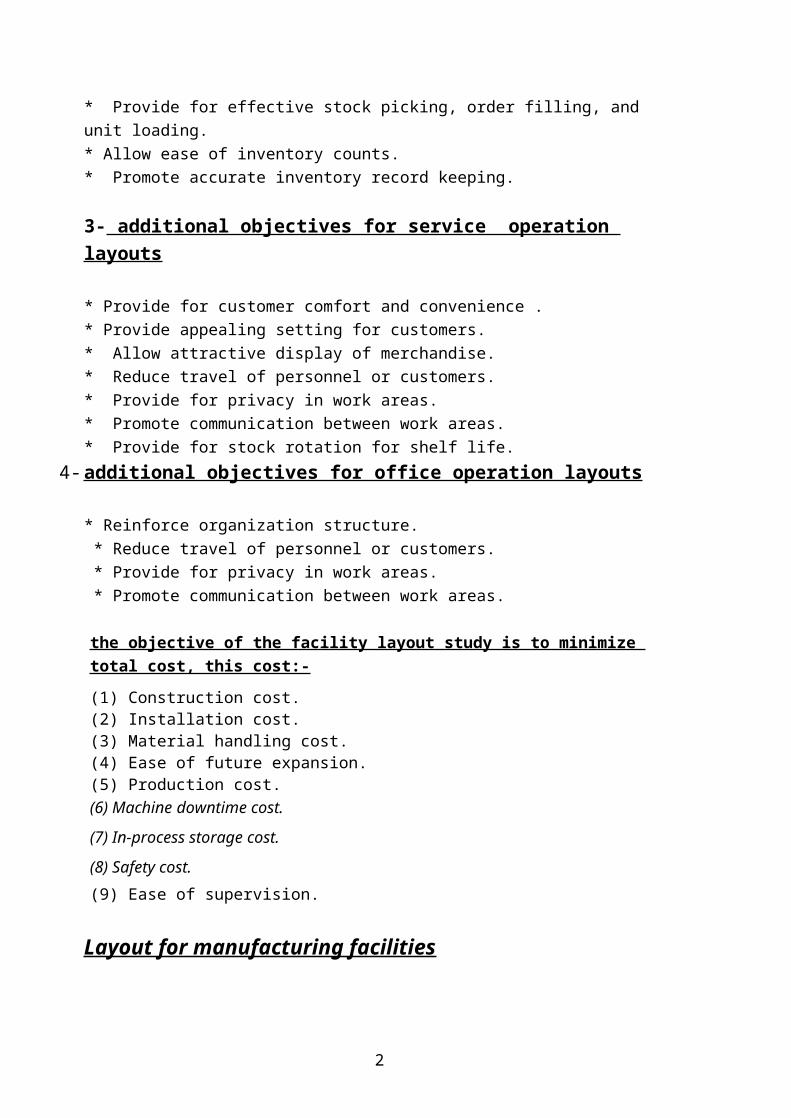
1-process layouts ( functional layouts, or job shops)
are designed to accommodate variety in product designs and smallbatches .Process layout use general –purpose machines that can bechanged over rapidly to new operations for different productdesigns. these machines are usually arranged according to type ofprocess being performed.
for example , all machining would be in one department ,allassembly in anther department ,and all painting in antherdepartment ,the materials –handling equipment generally consistsof forklift trucks and other mobile vehicles that allow for thevariety of paths followed through the facility by the productsproduced. the workers must change and adapt quickly to the multitude ofoperations to be performed on each unique batch of products beingproduced. These workers must be highly skilled & requireintensive job instructions And technical supervision.Process layout require ongoing(continues) planning, scheduling,and controlling functions to ensure an optimum amount of work ineach department and each workstation. Inventory in process islarge, the products are in the production system for relativelylong period of time.
3
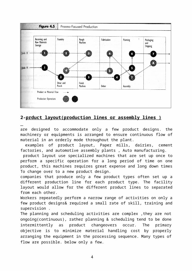
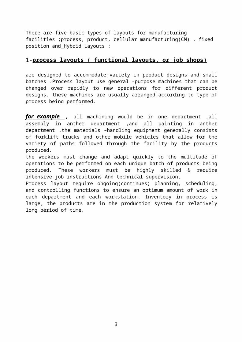
2-prduct layout(production lines or assembly lines ) are designed to accommodate only a few product designs. themachinery or equipments is arranged to ensure continuous flow ofmaterial in an orderly mode throughout the plant. examples of product layout, Paper mills, dairies, cementfactories, and automotive assembly plants , Auto manufacturing. product layout use specialized machines that are set up once toperform a specific operation for a long period of time on oneproduct, this machines requires great expense and long down timesTo change over to a new product design.companies that produce only a few product types often set up adifferent production line for each product type. The facilitylayout would allow for the different product lines to separatedfrom each other.Workers repeatedly perform a narrow range of activities on only afew product designs& required a small rate of skill, training andsupervision .The planning and scheduling activities are complex ,they are notongoing(continuous), rather planning & scheduling tend to be doneintermittently as product changeovers occur. The primaryobjective is to minimize material handling cost by properlyarranging the equipment in the processing sequence. Many types offlow are possible. below only a few.
4
Product layout
ADVANTAGES AND LIMITATIONS OF PRODUCT AND PROCESS LAYOUTS*
Product Layout
Advantages
1. Since the layout corresponds to the sequence of operations, smooth and logical flow lines result.2. Since the work from one process is fed directly into the next, small in-process inventories result.3. Total production time per unit is short.4. Since the machines are located in order to minimize distances between consecutive operations, material handling is reduced.
5
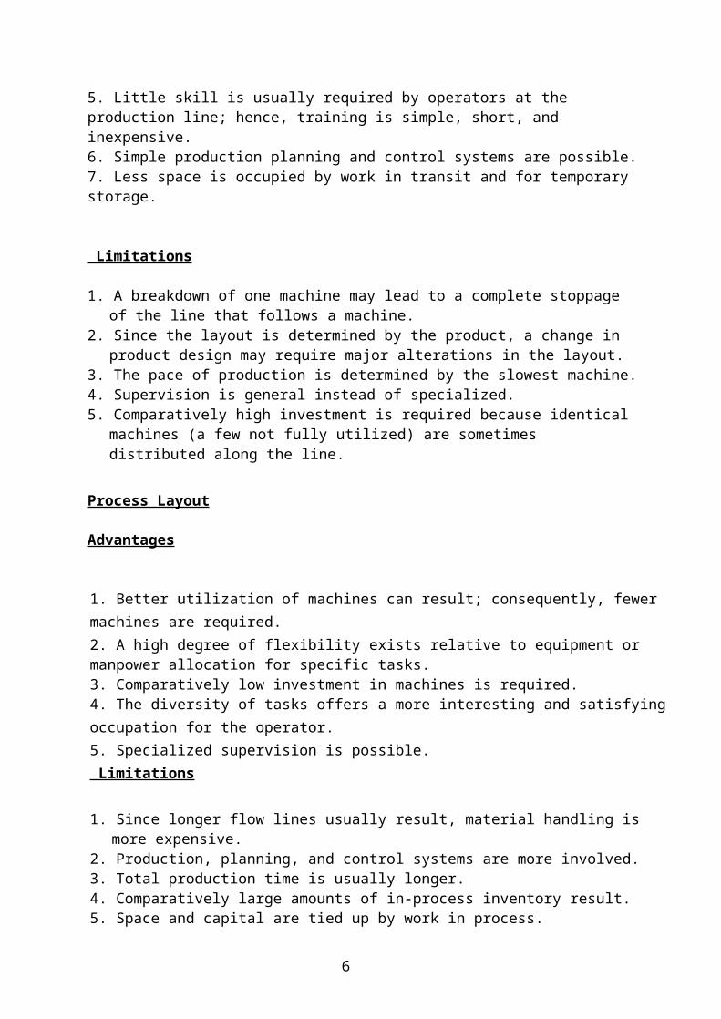
5. Little skill is usually required by operators at the production line; hence, training is simple, short, and inexpensive.6. Simple production planning and control systems are possible.7. Less space is occupied by work in transit and for temporary storage.
Limitations
1. A breakdown of one machine may lead to a complete stoppage of the line that follows a machine.
2. Since the layout is determined by the product, a change in product design may require major alterations in the layout.
3. The pace of production is determined by the slowest machine.4. Supervision is general instead of specialized.5. Comparatively high investment is required because identical
machines (a few not fully utilized) are sometimes distributed along the line.
Process Layout
Advantages
1. Better utilization of machines can result; consequently, fewer machines are required.2. A high degree of flexibility exists relative to equipment or manpower allocation for specific tasks.3. Comparatively low investment in machines is required.4. The diversity of tasks offers a more interesting and satisfyingoccupation for the operator.5. Specialized supervision is possible. Limitations
1. Since longer flow lines usually result, material handling is more expensive.
2. Production, planning, and control systems are more involved.3. Total production time is usually longer.4. Comparatively large amounts of in-process inventory result.5. Space and capital are tied up by work in process.
6
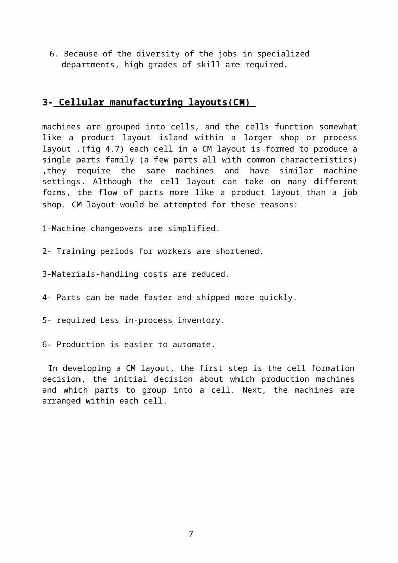
6. Because of the diversity of the jobs in specialized departments, high grades of skill are required.
3- Cellular manufacturing layouts(CM)
machines are grouped into cells, and the cells function somewhatlike a product layout island within a larger shop or processlayout .(fig 4.7) each cell in a CM layout is formed to produce asingle parts family (a few parts all with common characteristics),they require the same machines and have similar machinesettings. Although the cell layout can take on many differentforms, the flow of parts more like a product layout than a jobshop. CM layout would be attempted for these reasons:
1-Machine changeovers are simplified.
2- Training periods for workers are shortened.
3-Materials-handling costs are reduced.
4- Parts can be made faster and shipped more quickly.
5- required Less in-process inventory.
6- Production is easier to automate.
In developing a CM layout, the first step is the cell formationdecision, the initial decision about which production machinesand which parts to group into a cell. Next, the machines arearranged within each cell.
7

4- Fixed-Position LayoutsSome manufacturing and construction firms use a layout forarranging work that locates the product in a fixed position andtransports workers, materials, machines, and subcontractors toand from the product. Figure 5.6 demonstrates this type oflayout. Missile assembly, large aircraft assembly, shipconstruction, and bridge construction are examples of Fixed-position layouts . Fixed-position layouts are used when a prod-uct is very bulky, large, heavy, or fragile. The fixed-positionnature of the layout minimizes the amount of product movementrequired. Examples of fixed-position layout include largershipbuilding and airplane manufacturing. Here, the ship orairplane is too large to be moved around the shop, the variousstages of manufacture (particularly assembly) are performed inone place by bringing all tools to the plane or ship
8
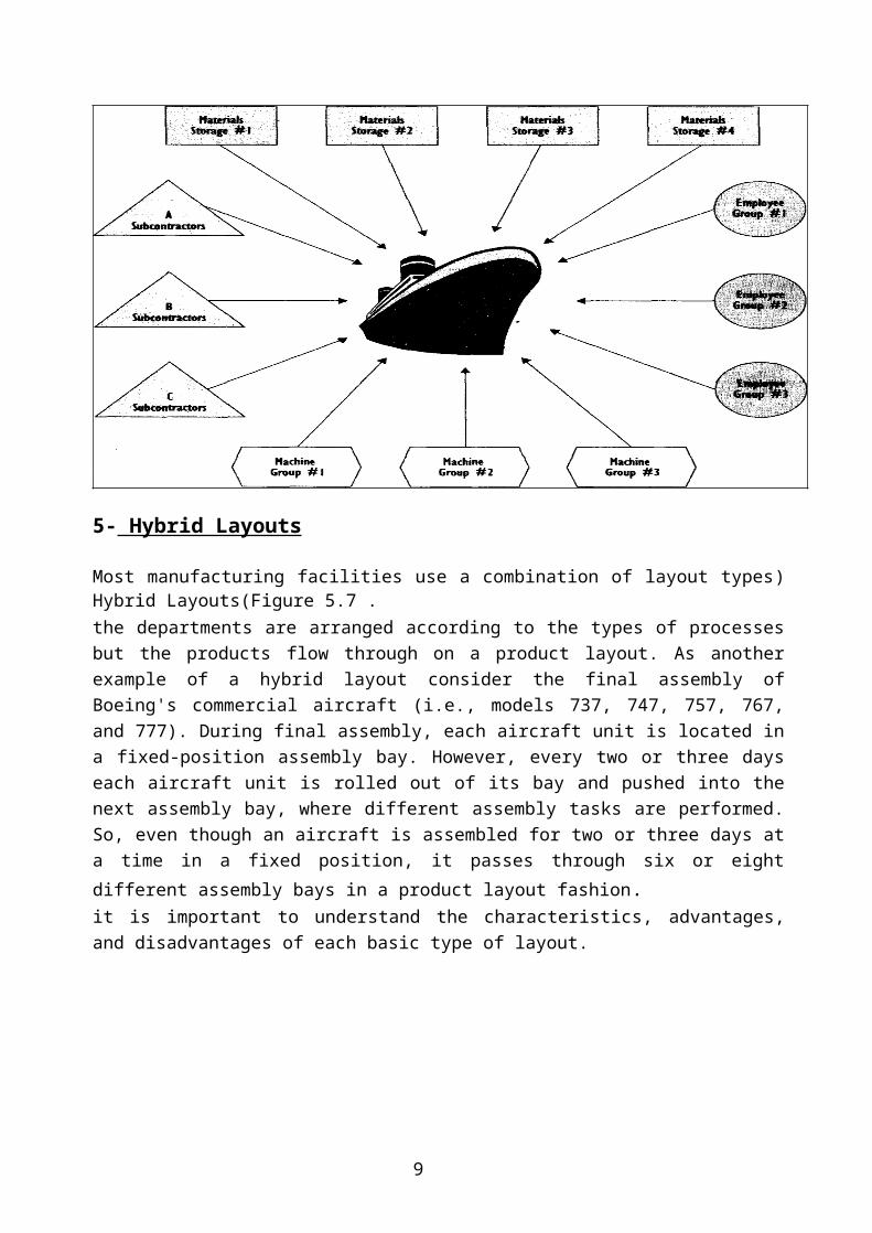
5- Hybrid Layouts
Most manufacturing facilities use a combination of layout types)Hybrid Layouts(Figure 5.7 .the departments are arranged according to the types of processesbut the products flow through on a product layout. As anotherexample of a hybrid layout consider the final assembly ofBoeing's commercial aircraft (i.e., models 737, 747, 757, 767,and 777). During final assembly, each aircraft unit is located ina fixed-position assembly bay. However, every two or three dayseach aircraft unit is rolled out of its bay and pushed into thenext assembly bay, where different assembly tasks are performed.So, even though an aircraft is assembled for two or three days ata time in a fixed position, it passes through six or eightdifferent assembly bays in a product layout fashion.it is important to understand the characteristics, advantages,and disadvantages of each basic type of layout.
9
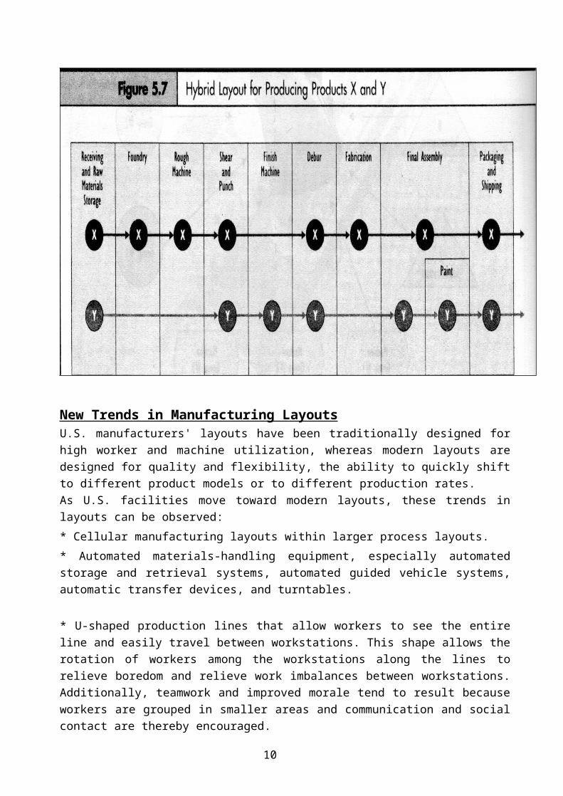
New Trends in Manufacturing Layouts U.S. manufacturers' layouts have been traditionally designed forhigh worker and machine utilization, whereas modern layouts aredesigned for quality and flexibility, the ability to quickly shiftto different product models or to different production rates.As U.S. facilities move toward modern layouts, these trends inlayouts can be observed:* Cellular manufacturing layouts within larger process layouts. * Automated materials-handling equipment, especially automatedstorage and retrieval systems, automated guided vehicle systems,automatic transfer devices, and turntables.
* U-shaped production lines that allow workers to see the entireline and easily travel between workstations. This shape allows therotation of workers among the workstations along the lines torelieve boredom and relieve work imbalances between workstations.Additionally, teamwork and improved morale tend to result becauseworkers are grouped in smaller areas and communication and socialcontact are thereby encouraged.
10

* More open work areas with fewer walls, partitions, or otherobstacles to clear views of adjacent workstations.* Smaller and more compact factory layouts. With more automationsuch as robots, less space needs to be provided for workers.Machines can be placed closer to each other, and materials andproducts travel shorter distances. * Less space provided for storage of inventories throughout thelayout.
Traditional facility layout versus modern layout
1- Characteristics of Traditional Layouts
* Chief objective( سي� ي� .High machine and worker utilization :(ال�هدف� ال�رئ��* Means of achieving objective: Long production runs, fixed jobassignments for workers in order to realize specialization-of-labor benefits, inventory to guard against machine breakdowns,constant production rates and with defects set aside for laterrework, and large production machines that are kept fullyutilized.* Appearance of layouts: Very large manufacturing-plant floor plans,extensive areas reserved for inventory, much space used for longconveyors and other materials-handling devices, large productionmachines requiring much floor space, L-shaped or linear productionlines, and generally underutilized floor space.
2- Characteristics of Modern Layouts*Chief objective: Product quality and flexibility, the ability tomodify production rates quickly and to change to different productmodels.*Means of achieving objective: Workers trained at many jobs, heavyinvestment in preventive maintenance, small machines easilychanged over to different product models, workers encouraged toexercise initiative in solving quality and other productionproblems as they occur, workers and machines shifted as needed tosolve production problems, production lines slowed down andmachine breakdown or quality problems solved as they occur, littleinventory carried, and workstations placed close together.
11
*Appearance of layouts: Relatively small manufacturing-plant floorplans, compact and tightly packed layouts, large percentage offloor space used for production, less floor space occupied byinventory or materials-handling devices, and U-shaped productionlines.
Example
The Whittemore Dairy of Floyd, Virginia, has decided to move itsoperations to a more modern plant. Remodeling and relayout of theold facility were considered but ruled out because of the age ofthe old building. the new facility produced four products. theforecasted quantity and other general data, are shown in Table6.1., the following equipment needs To produce these products are:(a) Pasteurizer (one).(b) Homogenizer (one).(c) Pasteurization storage tank (one).(d) Filling machine (three) for placing products in cartons.(e) Cooler (one).(f) Laboratory equipment (one complete lab) for testing products.(g) Byproduct Mixing Vat and other equipment for producing cottage cheese and buttermilk. The goal is located the equipment in order to minimize total costs.
12
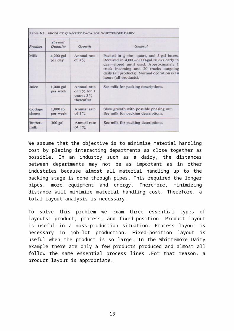
We assume that the objective is to minimize material handlingcost by placing interacting departments as close together aspossible. In an industry such as a dairy, the distancesbetween departments may not be as important as in otherindustries because almost all material handling up to thepacking stage is done through pipes. This required the longerpipes, more equipment and energy. Therefore, minimizingdistance will minimize material handling cost. Therefore, atotal layout analysis is necessary.
To solve this problem we exam three essential types oflayouts: product, process, and fixed-position. Product layoutis useful in a mass-production situation. Process layout isnecessary in job-lot production. Fixed-position layout isuseful when the product is so large. In the Whittemore Dairyexample there are only a few products produced and almost allfollow the same essential process lines .For that reason, aproduct layout is appropriate.
13
Lecture(8)
Systematic Layout Planning (SLP)
Systematic layout planning is an organized approach to layoutplanning Figure 6.2 depicts the stages in the procedure, theconstruction of the actual layout is a complex problem .thisFigure show SLP Steps :-
14
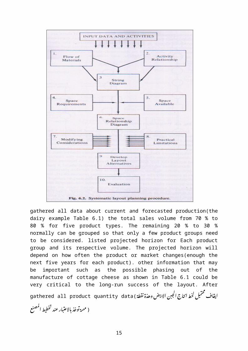
gathered all data about current and forecasted production(thedairy example Table 6.1) the total sales volume from 70 % to80 % for five product types. The remaining 20 % to 30 %normally can be grouped so that only a few product groups needto be considered. listed projected horizon for Each productgroup and its respective volume. The projected horizon willdepend on how often the product or market changes(enough thenext five years for each product). other information that maybe important such as the possible phasing out of themanufacture of cottage cheese as shown in Table 6.1 could bevery critical to the long-run success of the layout. After
gathered all product quantity data( ط�ة� ق� ة� ن�� د� ض� وه�� ي� ��ب ن! الا ب# اج! ال�ج# ت�� ط اب+* اف� م�حت�م�ل ل�خ�� ق�� ان��ع ط ال�مصن� طي� خ� د ت�� ار ع�ت� ت# الاع�ت� د� ب�# وخ�� ( م�همة� ت��
15

Step 1 of the SLP(Flow of Materials)
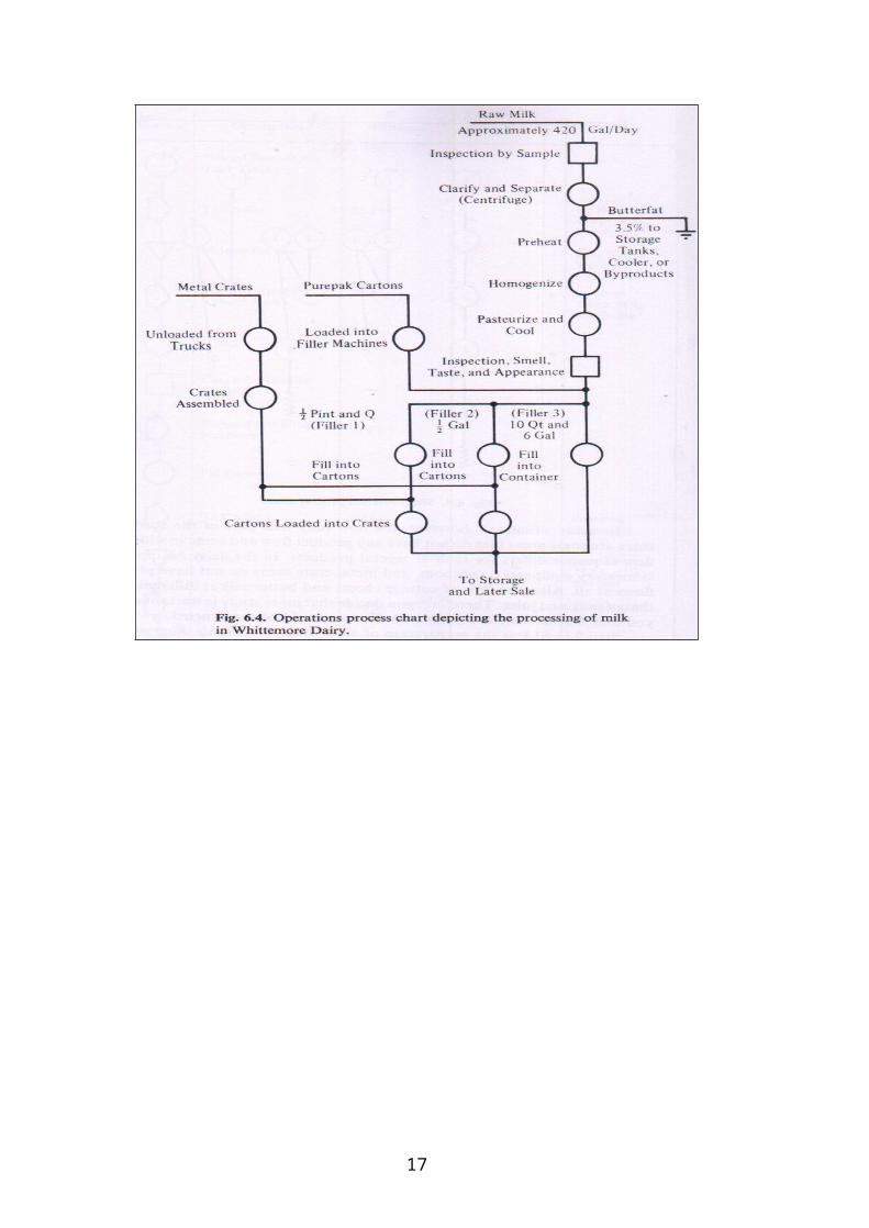
procedure is the preparation of process charts graphicallydepicting the flow of the material through the plant. If thereare a few products, we made separate operations process chartfor each product. If there are many products, we use amultiproduct process chart. Actually, an operation processchart depicts only the operations and inspections& the flowprocess chart shows operations and inspections ,transportations, delays, and storages. In the operations
process chart(fig.6.4) ( ات� ج# Iت ج! واخ�د او ع�دة� م�ن� ت� ي� خ�الة� م�ن� ات� ف� سلسل ال�عملت� طط ت�� (ع�مل م�خ�
Figure 6.4 illustrates an operations process chart for processing milk for Whittemore Dairy
16
17

a line is drawn at the upper right-hand corner of the paperreflecting the start of the largest component. Other parts ofmaterials are fed in from the left. The sequence is from top tobottom and only shown. operations and inspections. Figure 6.5shown a multiproduct process chart ,the chart demonstrates thatthe only difference is that the multiple products are listedacross the top and the flow in from top to bottom only.A flow process chart is the same as the operations processchart, but a flow process chart shows more information about aspecific part or item. Figure 6.6 shows a flow process chartfor processing juice in the old dairy. This chart, showingstorages and transportations, gives more detail than anoperations process chart does.
in job shop, it is difficult, if not impossible, to representall the flow in a few charts , Many products may be producedthat require a large number of charts, In this situation usesa from-to chart may be more appropriate.
A from-to chart shows the number of trips from one area to anotherarea and is based on historical data or proposed production.The trips can be weighted by product volume or some other
18
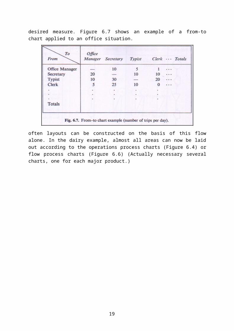
desired measure. Figure 6.7 shows an example of a from-tochart applied to an office situation.
often layouts can be constructed on the basis of this flowalone. In the dairy example, almost all areas can now be laidout according to the operations process charts (Figure 6.4) orflow process charts (Figure 6.6) (Actually necessary severalcharts, one for each major product.)
19

In many situations, , some areas do not have any product flow and flow sequence differs for each of several products. In thedairy example the laboratory equipment, restroom, and metal crate areas do not have product flows at all. Also, the flow of cottage cheese and buttermilk is different from that of milk and juice.
Step 2 in SLP(activity relationship)
is the preparation of an activity relationship diagram that showsthe desired closeness of departments and areas within the
plant(ها عض����� س����ام ال�مطل����وت# م�ن! ن�# ر ت# الاق�� � سلس����ل وق����� ات� ت�� طلت����# ع وم�ي� ي� ال�مص����ن� اح����ة� ف� ج ال�مس����احة� ال�مت� وض������ .( ت�� The
20
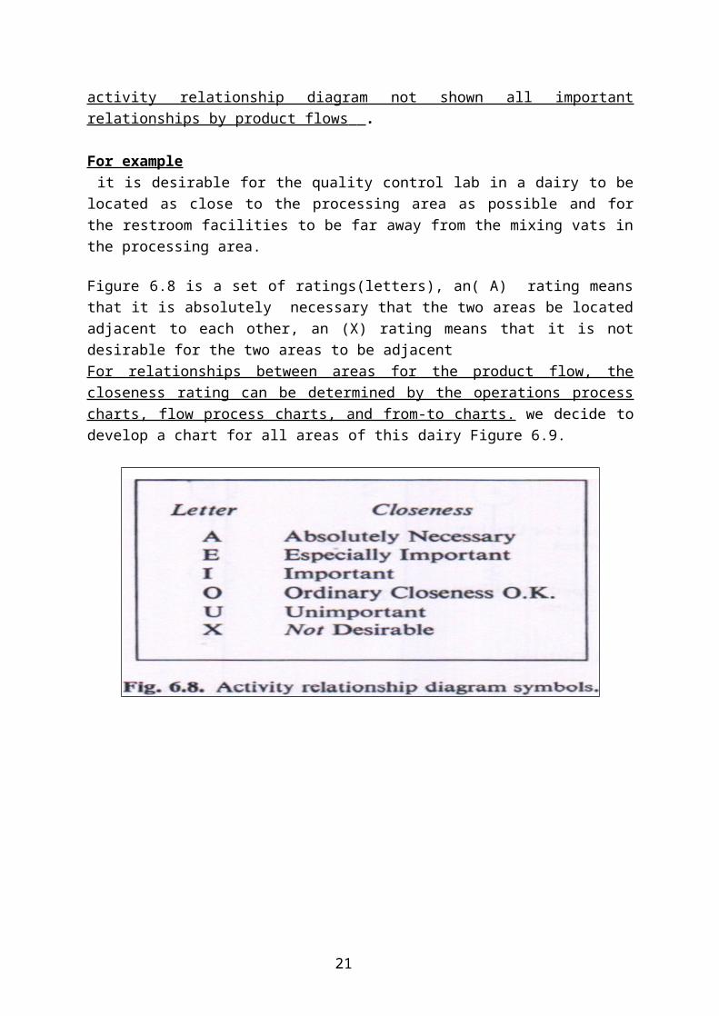
activity relationship diagram not shown all importantrelation ships by product flows .
For example it is desirable for the quality control lab in a dairy to belocated as close to the processing area as possible and forthe restroom facilities to be far away from the mixing vats inthe processing area.
Figure 6.8 is a set of ratings(letters), an( A) rating meansthat it is absolutely necessary that the two areas be locatedadjacent to each other, an (X) rating means that it is notdesirable for the two areas to be adjacent For relationships between areas for the product flow, thecloseness rating can be determined by the operations processcharts, flow process charts, and from-to charts. we decide todevelop a chart for all areas of this dairy Figure 6.9.
21
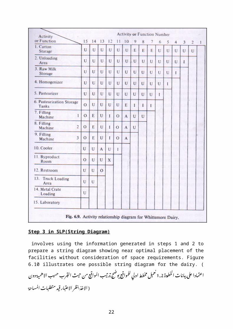
Step 3 in SLP(String Diagram)
involves using the information generated in steps 1 and 2 toprepare a string diagram showing near optimal placement of thefacilities without consideration of space requirements. Figure6.10 illustrates one possible string diagram for the dairy. (
ط��وة� ات� ال�خ� اب��� ت� �م�ادا ع�لي ب� ة� دون!1,2اع�ت� رت# ح�س��ب# الاه�مي�� بr ال�ق�� ع م�ن! ح�ي� ب# ال�مواق���� ي� رب+� ج ت���� وض��� ع ت�� ط��ط اولي� ل�لمواق��� عم��ل م�خ� ن��ات� ال�مساحة� طلت# د م�ي� ت� ار ق�� ت# ر الاع�ت� ظ| ي� د� ب�# (الاخ��
22
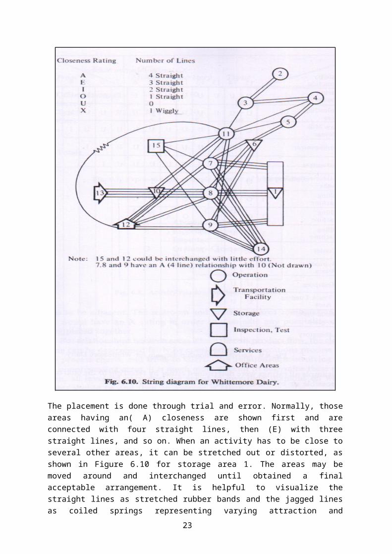
The placement is done through trial and error. Normally, thoseareas having an( A) closeness are shown first and areconnected with four straight lines, then (E) with threestraight lines, and so on. When an activity has to be close toseveral other areas, it can be stretched out or distorted, asshown in Figure 6.10 for storage area 1. The areas may bemoved around and interchanged until obtained a finalacceptable arrangement. It is helpful to visualize thestraight lines as stretched rubber bands and the jagged linesas coiled springs representing varying attraction and
23
repulsion forces. Therefore, an A rating would imply fourrubber bands pulling the areas together while an I ratingwould imply only two rubber bands. Many diagrams andarrangements will probably draw before obtained a good layoutis. Normally, two or more alternatives are developed.Essentially, these alternatives each constitute a finallayout. added Space and made some modifications, but theoverall picture should not change much.
Step 4 in SLP (Space Requirements)
the most important step, called the adjustment step. determinedspace needs , space availability; space requirements This canbe done through estimates or calculations adjustment of pastareas. This is a critical stage, but for almost allorganizations, in-process storage and machine areas can bepredicted accurately, so that space requirements can bedetermined. requirements are known, it is necessary toconsider the space available
Step 5 in SLP (Space Available)
In some cases, the layout must fit existing buildings, thespace available is highly restricted. In other cases, thecapital budget is the main restriction, and, therefore, thespace availability may be less restricted. Must consider theconstraint of the space requirements and space availability,the space requirements and space availability must be balanced
Step 6 in SLP (Space Relationship)
the space relationship diagram. where, space is added to thestring diagram developed in step 3. By using the space fromsteps 4 and 5 and the diagram from step 3, a layout is con-structed , but many trials necessary before developed anacceptable layout. Often, a number of blocks representing thespace requirements of a given area are shuffled around untilobtained good layouts.
24
Steps 7 and 8 in SLP(Modifying Considerations & Practical Limitation)
Considered the practical limitations, At least developed twoalternative layouts. These alternatives should be blockdiagrams showing broad areas and general shapes.
Steps 9 in SLP (Develop Layout Alternative)
At this stage, the two or more alternatives examined be usingsome criterion & chose the best one. Usually, the criterion isa subjective estimate of the combined effects of severalcriteria Steps 10 in SLP (Evaluation )
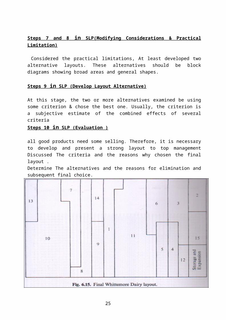
all good products need some selling. Therefore, it is necessaryto develop and present a strong layout to top managementDiscussed The criteria and the reasons why chosen the finallayout .Determine The alternatives and the reasons for elimination andsubsequent final choice.
25
Computerized Layout Planning (Optional)
computerized layout packages take the activity relationshipcharts developed in Step 2 or from-to charts developed in step1 (depending on which package is used) and generate anyspecified number of layouts. These can be scored and comparedby the computer and/or the layout analyst. The final decisionmust be made by the manager. The chief advantage in com-puterized packages is generated the large number ofalternatives .There are many computerized plant layout packages available,ALDEP, CORELAP, and CRAFT. Basically, ALDEP and CORELAP are"construction" types in that layouts are generated fromscratch. CRAFT is an "improvement" type in that an initiallayout is required and improvements are made upon it. Someother packages are RUGR, LAOPT, PLANET, LSP, and RMS COMP I.Only one package, ALDEP, will be considered here. ALDEP ischosen for this presentation because it was one of the firstpackages developed and it is relatively simple and easy tounderstand.
26