An Isolated Power Factor Corrected Cuk Converter ... - MDPI
24
electronics Article An Isolated Power Factor Corrected Cuk Converter with Integrated Magnetics for Brushless DC Ceiling Fan Applications Hashim Raza Khan 1,2 , Majida Kazmi 1, *, Haris Bin Ashraf 1 , Muhammad Hashir Bin Khalid 3 , Abul Hasan 1,2 and Saad Ahmed Qazi 1,2 Citation: Khan, H.R.; Kazmi, M.; Ashraf, H.B.; Hashir Bin Khalid, M.; Hasan, A.; Qazi, S.A. An Isolated Power Factor Corrected Cuk Converter with Integrated Magnetics for Brushless DC Ceiling Fan Applications. Electronics 2021, 10, 1720. https://doi.org/10.3390/ electronics10141720 Academic Editor: Bor-Ren Lin Received: 14 June 2021 Accepted: 12 July 2021 Published: 17 July 2021 Publisher’s Note: MDPI stays neutral with regard to jurisdictional claims in published maps and institutional affil- iations. Copyright: © 2021 by the authors. Licensee MDPI, Basel, Switzerland. This article is an open access article distributed under the terms and conditions of the Creative Commons Attribution (CC BY) license (https:// creativecommons.org/licenses/by/ 4.0/). 1 Faculty of Electrical and Computer Engineering, NED University of Engineering and Technology, Karachi 75270, Pakistan; [email protected] (H.R.K.); [email protected] (H.B.A.); [email protected] (A.H.); [email protected] (S.A.Q.) 2 Neuro-Computation Lab, National Center of Artificial Intelligence, Karachi 75270, Pakistan 3 Courant Institute of Mathematical Sciences, New York University, New York, NY 10012, USA; [email protected] * Correspondence: [email protected] Abstract: The usage of BLDC motors in the low-power range is increasing rapidly in home appliances such as ceiling fans. This has necessitated the development of reliable, compact and efficient AC-DC power supplies for motor drive circuitry. This paper presents a power supply design consisting of an AC-DC isolated PFC Cuk converter with integrated magnetics that supplies a single-shunt voltage source inverter for the sensorless drive of the BLDC fan motor. The proposed power supply design is comprised of an integrated magnetics structure in which the two inductors and the transformer windings share the same core. The zero input and output ripple current conditions have been derived from the reluctance model of the magnetic assembly. Smooth operation of the motor by minimizing the motor torque ripples is evident from the results. The Cuk converter operates in continuous conduction mode (CCM), employing the current multiplier method. The CCM-based current multiplier control loop ensures a near-unity power factor as well as low total harmonic distortion in the supply current. The current loop also provides over-current protection, enhancing reliability of the system. Moreover, the speed of the BLDC motor is controlled by the field oriented control (FOC) algorithm, which enables direct operation with alternate energy sources such as batteries and solar photovoltaic panels. The performance of the proposed supply is validated: motor torque ripple is reduced to only 2.14% while maintaining 0.999 power factor and only 4.72% THD at full load. Failure modes analysis has also been performed through software simulations, using the PLECS simulation environment. Due to the reliable power supply design with low ripples, it is well suited for low-power BLDC motors in home appliances and small power tools, in addition to ceiling fans. Keywords: isolated switch mode power supply; integrated magnetics; power factor correction; ceiling fan; BLDC motor drive; torque ripple; sensorless speed control; field oriented control; failure modes analysis 1. Introduction Electrical and electronic equipment design in the 21st century is invariably focused on energy efficiency. Most home appliances have already been replaced by energy efficient upgrades: inverter-based designs have replaced conventional solutions for air conditioners and refrigerators, LEDs have supplanted fluorescent lights, and LED TVs have substituted CRT-based televisions, to name a few examples [1]. Among all household appliances, electric fans are one of the most widespread in both urban and rural environments [2]. Ceiling fans are extensively used in summer seasons all around the world, constituting Electronics 2021, 10, 1720. https://doi.org/10.3390/electronics10141720 https://www.mdpi.com/journal/electronics
-
Upload
khangminh22 -
Category
Documents
-
view
0 -
download
0
Transcript of An Isolated Power Factor Corrected Cuk Converter ... - MDPI
electronics
Article
An Isolated Power Factor Corrected Cuk Converter withIntegrated Magnetics for Brushless DC CeilingFan Applications
Hashim Raza Khan 1,2, Majida Kazmi 1,*, Haris Bin Ashraf 1, Muhammad Hashir Bin Khalid 3, Abul Hasan 1,2
and Saad Ahmed Qazi 1,2
�����������������
Citation: Khan, H.R.; Kazmi, M.;
Ashraf, H.B.; Hashir Bin Khalid, M.;
Hasan, A.; Qazi, S.A. An Isolated
Power Factor Corrected Cuk
Converter with Integrated Magnetics
for Brushless DC Ceiling Fan
Applications. Electronics 2021, 10,
1720. https://doi.org/10.3390/
electronics10141720
Academic Editor: Bor-Ren Lin
Received: 14 June 2021
Accepted: 12 July 2021
Published: 17 July 2021
Publisher’s Note: MDPI stays neutral
with regard to jurisdictional claims in
published maps and institutional affil-
iations.
Copyright: © 2021 by the authors.
Licensee MDPI, Basel, Switzerland.
This article is an open access article
distributed under the terms and
conditions of the Creative Commons
Attribution (CC BY) license (https://
creativecommons.org/licenses/by/
4.0/).
1 Faculty of Electrical and Computer Engineering, NED University of Engineering and Technology,Karachi 75270, Pakistan; [email protected] (H.R.K.); [email protected] (H.B.A.);[email protected] (A.H.); [email protected] (S.A.Q.)
2 Neuro-Computation Lab, National Center of Artificial Intelligence, Karachi 75270, Pakistan3 Courant Institute of Mathematical Sciences, New York University, New York, NY 10012, USA;
[email protected]* Correspondence: [email protected]
Abstract: The usage of BLDC motors in the low-power range is increasing rapidly in home appliancessuch as ceiling fans. This has necessitated the development of reliable, compact and efficient AC-DCpower supplies for motor drive circuitry. This paper presents a power supply design consisting of anAC-DC isolated PFC Cuk converter with integrated magnetics that supplies a single-shunt voltagesource inverter for the sensorless drive of the BLDC fan motor. The proposed power supply designis comprised of an integrated magnetics structure in which the two inductors and the transformerwindings share the same core. The zero input and output ripple current conditions have beenderived from the reluctance model of the magnetic assembly. Smooth operation of the motor byminimizing the motor torque ripples is evident from the results. The Cuk converter operates incontinuous conduction mode (CCM), employing the current multiplier method. The CCM-basedcurrent multiplier control loop ensures a near-unity power factor as well as low total harmonicdistortion in the supply current. The current loop also provides over-current protection, enhancingreliability of the system. Moreover, the speed of the BLDC motor is controlled by the field orientedcontrol (FOC) algorithm, which enables direct operation with alternate energy sources such asbatteries and solar photovoltaic panels. The performance of the proposed supply is validated: motortorque ripple is reduced to only 2.14% while maintaining 0.999 power factor and only 4.72% THDat full load. Failure modes analysis has also been performed through software simulations, usingthe PLECS simulation environment. Due to the reliable power supply design with low ripples, it iswell suited for low-power BLDC motors in home appliances and small power tools, in addition toceiling fans.
Keywords: isolated switch mode power supply; integrated magnetics; power factor correction;ceiling fan; BLDC motor drive; torque ripple; sensorless speed control; field oriented control; failuremodes analysis
1. Introduction
Electrical and electronic equipment design in the 21st century is invariably focused onenergy efficiency. Most home appliances have already been replaced by energy efficientupgrades: inverter-based designs have replaced conventional solutions for air conditionersand refrigerators, LEDs have supplanted fluorescent lights, and LED TVs have substitutedCRT-based televisions, to name a few examples [1]. Among all household appliances,electric fans are one of the most widespread in both urban and rural environments [2].Ceiling fans are extensively used in summer seasons all around the world, constituting
Electronics 2021, 10, 1720. https://doi.org/10.3390/electronics10141720 https://www.mdpi.com/journal/electronics
Electronics 2021, 10, 1720 2 of 24
approximately 6–9% of the total energy used in the residential sector. Improvementsin ceiling fan design offer enormous potential for energy savings. The most significantimprovement is the use of a brushless DC (BLDC) motor in place of an induction motor,which can reduce power consumption by 50% [3,4]. Although the technology of permanentmagnet BLDC motors for fans is more complex, the rising energy cost has tipped thereturn on investment in its favor [5,6]. Two types of PM motors are currently being wellreceived for ceiling fan applications, namely the BLDC motor and the permanent magnetsynchronous motor (PMSM). Both these machines are very similar, except that the BLDChas a trapezoidal back EMF, while the PMSM has a sinusoidal back EMF. BLDC motorsare commonly used in designs that require cost-effective solutions, due to their low cost ofmanufacturing [7].
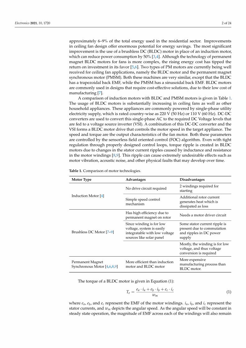
A comparison of induction motors with BLDC and PMSM motors is given in Table 1.The usage of BLDC motors is substantially increasing in ceiling fans as well as otherhousehold appliances. These appliances are commonly powered by single-phase utilityelectricity supply, which is rated country-wise as 220 V (50 Hz) or 110 V (60 Hz). DC-DCconverters are used to convert this single-phase AC to the required DC Voltage levels thatare fed to a voltage source inverter (VSI). A combination of this DC-DC converter and theVSI forms a BLDC motor drive that controls the motor speed in the target appliance. Thespeed and torque are the output characteristics of the fan motor. Both these parametersare controlled by the sensorless field oriented control (FOC) algorithm. Even with tightregulation through properly designed control loops, torque ripple is created in BLDCmotors due to changes in the stator current ripples caused by inductance and resistancein the motor windings [8,9]. This ripple can cause extremely undesirable effects such asmotor vibration, acoustic noise, and other physical faults that may develop over time.
Table 1. Comparison of motor technologies.
Motor Type Advantages Disadvantages
Induction Motor [4]
No drive circuit required 2 windings required forstarting
Simple speed controlmechanism
Additional rotor currentgenerates heat which isdissipated as loss
Brushless DC Motor [7–9]
Has high efficiency due topermanent magnet on rotor Needs a motor driver circuit
Since winding is for lowvoltage, system is easilyintegratable with low voltagesources like solar panel
Some stator current ripple ispresent due to commutationand ripples in DC powersupply
Mostly, the winding is for lowvoltage, and thus voltageconversion is required
Permanent MagnetSynchronous Motor [4,6,8,9]
More efficient than inductionmotor and BLDC motor
More expensivemanufacturing process thanBLDC motor.
The torque of a BLDC motor is given in Equation (1):
Te =ea · ia + eb · ib + ec · ic
wm(1)
where ea, eb, and ec represent the EMF of the motor windings. ia, ib, and ic represent thestator currents, and wm depicts the angular speed. As the angular speed will be constant insteady state operation, the magnitude of EMF across each of the windings will also remain
Electronics 2021, 10, 1720 3 of 24
constant. Therefore, the parameter that is responsible for the torque ripple is the statorcurrent in each phase.
There are two main sources of stator current ripples. The first source is the com-mutation of the BLDC motor through the VSI that causes a ripple that has a frequencycorresponding to the fundamental frequency at which the VSI is being switched. Thereare several mitigation strategies for this kind of ripple. First, the magnetic design of thestator and rotor can be improved by altering the machine design [10–12]. Other techniquesinclude the design of a torque controller [13,14], a current shaping model [15,16], inputvoltage controller [17], feedforward current controller [18], and direct torque control [19,20]methods. The second source of ripple is the DC power supply of the VSI. If the DC sourcesupplying the VSI contains current and voltage ripples, they will be reflected in the statorcurrents. Since motor drives are commonly supplied by DC-DC converters, the outputripples of the converter will have a frequency that corresponds to the switching frequencyof the MOSFET in the DC-DC converter. In order to mitigate the stator current ripple, theoutput current ripple of the converter must be minimized. This is why converters thatexhibit a continuous output current are suitable for BLDC motor drive applications.
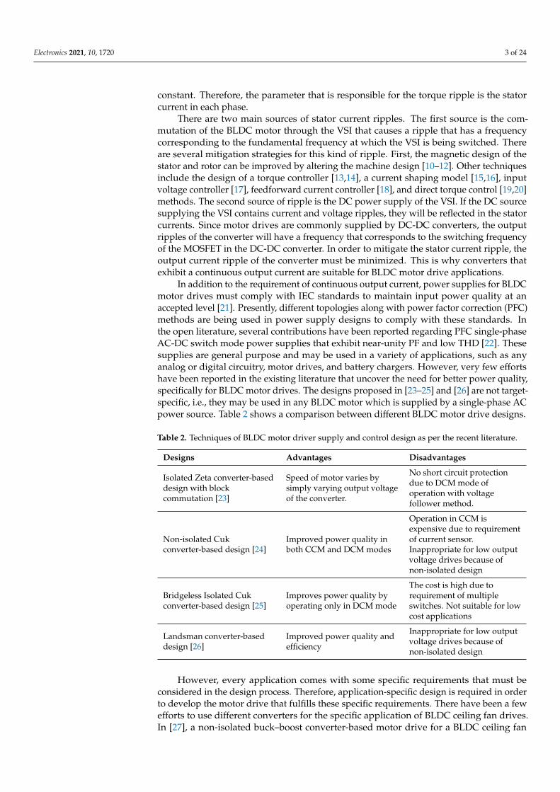
In addition to the requirement of continuous output current, power supplies for BLDCmotor drives must comply with IEC standards to maintain input power quality at anaccepted level [21]. Presently, different topologies along with power factor correction (PFC)methods are being used in power supply designs to comply with these standards. Inthe open literature, several contributions have been reported regarding PFC single-phaseAC-DC switch mode power supplies that exhibit near-unity PF and low THD [22]. Thesesupplies are general purpose and may be used in a variety of applications, such as anyanalog or digital circuitry, motor drives, and battery chargers. However, very few effortshave been reported in the existing literature that uncover the need for better power quality,specifically for BLDC motor drives. The designs proposed in [23–25] and [26] are not target-specific, i.e., they may be used in any BLDC motor which is supplied by a single-phase ACpower source. Table 2 shows a comparison between different BLDC motor drive designs.
Table 2. Techniques of BLDC motor driver supply and control design as per the recent literature.
Designs Advantages Disadvantages
Isolated Zeta converter-baseddesign with blockcommutation [23]
Speed of motor varies bysimply varying output voltageof the converter.
No short circuit protectiondue to DCM mode ofoperation with voltagefollower method.
Non-isolated Cukconverter-based design [24]
Improved power quality inboth CCM and DCM modes
Operation in CCM isexpensive due to requirementof current sensor.Inappropriate for low outputvoltage drives because ofnon-isolated design
Bridgeless Isolated Cukconverter-based design [25]
Improves power quality byoperating only in DCM mode
The cost is high due torequirement of multipleswitches. Not suitable for lowcost applications
Landsman converter-baseddesign [26]
Improved power quality andefficiency
Inappropriate for low outputvoltage drives because ofnon-isolated design
However, every application comes with some specific requirements that must beconsidered in the design process. Therefore, application-specific design is required in orderto develop the motor drive that fulfills these specific requirements. There have been a fewefforts to use different converters for the specific application of BLDC ceiling fan drives.In [27], a non-isolated buck–boost converter-based motor drive for a BLDC ceiling fan
Electronics 2021, 10, 1720 4 of 24
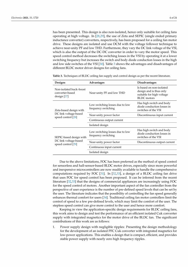
has been presented. This design is also non-isolated, hence only suitable for ceiling fansoperating at high voltage. In [28,29], the use of Zeta and SEPIC (single ended primaryinductance converter) converters, respectively, has been proposed for a ceiling fan motordrive. These designs are isolated and use DCM with the voltage follower technique toachieve near-unity PF and low THD. Furthermore, they vary the DC link voltage of the VSI,which is also the output of the DC-DC converter in order to vary the motor speed. Thisspeed control method decreases the switching losses in the VSI by operating it at a lowerswitching frequency but increases the switch and body diode conduction losses in the highand low side switches of the VSI [30]. Table 3 shows the advantages and disadvantages ofdifferent BLDC motor driver designs for ceiling fans.
Table 3. Techniques of BLDC ceiling fan supply and control design as per the recent literature.
Designs Advantages Disadvantages
Non-isolated buck–boostconverter-baseddesign [27]
Near-unity PF and low THD
Is based on non-isolateddesign and is thus onlysuitable for high voltageBLDC motors
Zeta-based design withDC link voltage-basedspeed control [28]
Low switching losses due to lowfrequency switching
Has high switch and bodydiode conduction losses inswitches of the VSI
Near-unity power factor Discontinuous input current
Continuous output current
Isolated design
SEPIC-based design withDC link voltage-basedspeed control [29]
Low switching losses due to lowfrequency switching
Has high switch and bodydiode conduction losses inswitches of the VSI
Near-unity power factor Discontinuous output current
Continuous input current
Isolated design
Due to the above limitations, FOC has been preferred as the method of speed controlfor sensorless and hall-sensor-based BLDC motor drives, especially since more powerfuland inexpensive microcontrollers are now readily available to handle the comprehensivecomputations required by FOC [31]. In [32,33], a design of a BLDC ceiling fan drivethat uses FOC for speed control has been proposed. It can be inferred from the recentliterature [32,33] that the designs of commercial appliances are increasingly using FOCfor the speed control of motors. Another important aspect of the fan controller from theperspective of user experience is the number of pre-defined speed levels that can be set bythe user. The literature indicates that the possibility of controlling the fan speed generallyenhances thermal comfort for users [34]. Traditional ceiling fan motor controllers limit thecontrol of speed to a few pre-defined levels, which may limit the comfort of the user. Thestepless speed control can give more control to the user and hence more comfort.
Keeping in view the application-specific design requirements for BLDC ceiling fans,this work aims to design and test the performance of an efficient isolated Cuk convertersupply with integrated magnetics for the motor drive of the BLDC fan. The significantcontributions of this work are as follows:
1. Power supply design with negligible ripples: Presenting the design methodologyfor the development of an isolated PFC Cuk converter with integrated magnetics forlow-power applications. This enables a design that is compact, efficient, and providesstable power supply with nearly zero high frequency ripples.
Electronics 2021, 10, 1720 5 of 24
2. BLDC fan operation with low torque ripple: Using the Cuk converter to incorporatecontinuous input and output currents in the AC-DC supply design. This minimizesthe current ripples and ensures less torque ripple in the BLDC fan motor.
3. IEC standards compliance: Deploying the isolated Cuk converter in continuousconduction mode (CCM) with the current multiplier technique. This enables powerfactor correction (PFC) and a total harmonic distortion (THD) reduction along withan additional feature of over-current protection.
4. Failure modes analysis: A comprehensive analysis with common fault conditions ofthe ceiling fan and their impact on the proposed power supply is presented.
The rest of this paper is organized as follows: the preliminary concepts used in thiswork are discussed in Section 2. The AC-DC PFC power supply topology, along withthe design methodology, is discussed in Section 3. The system performance validationthat includes the modeling and simulation approach is described in Section 4. The resultsand performance comparison with similar topologies are discussed in Section 5. Theconcluding remarks are presented in Section 6. Appendix A includes the list of acronymsused throughout the paper, the notations along with their units, and the parameters of theceiling fan BLDC motor in Tables A1–A3 respectively.
2. Background
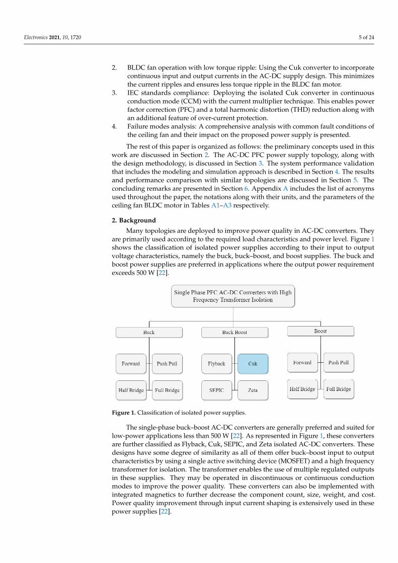
Many topologies are deployed to improve power quality in AC-DC converters. Theyare primarily used according to the required load characteristics and power level. Figure 1shows the classification of isolated power supplies according to their input to outputvoltage characteristics, namely the buck, buck–boost, and boost supplies. The buck andboost power supplies are preferred in applications where the output power requirementexceeds 500 W [22].
Figure 1. Classification of isolated power supplies.
The single-phase buck–boost AC-DC converters are generally preferred and suited forlow-power applications less than 500 W [22]. As represented in Figure 1, these convertersare further classified as Flyback, Cuk, SEPIC, and Zeta isolated AC-DC converters. Thesedesigns have some degree of similarity as all of them offer buck–boost input to outputcharacteristics by using a single active switching device (MOSFET) and a high frequencytransformer for isolation. The transformer enables the use of multiple regulated outputsin these supplies. They may be operated in discontinuous or continuous conductionmodes to improve the power quality. These converters can also be implemented withintegrated magnetics to further decrease the component count, size, weight, and cost.Power quality improvement through input current shaping is extensively used in thesepower supplies [22].
Electronics 2021, 10, 1720 6 of 24
A brief overview of the Flyback, SEPIC, Zeta, and Cuk power supply topologies ispresented here. The isolated Flyback converter’s high frequency transformer providesisolation, electrical safety, lower cost, and simple control. This power supply is a popularchoice in low-power applications for designers due to the lower component count andsimple control [22]. The isolated Cuk converter exhibits brilliant power quality at the inputAC as well as output DC side. In this design, energy is transferred through capacitors;therefore, the input and output currents are continuous. This design offers very lowswitching current ripple, wide range of input and output voltage, small size, naturalprotection against inrush current, and high overall conversion efficiency [22]. The isolatedSEPIC-based power supply is another design that exhibits brilliant power quality at theinput AC and output DC side. Low component count, small size, and fast dynamicresponse make this design a popular choice for applications where a high degree ofefficiency, reliability, and power quality are required [22]. The isolated Zeta converter-based power supply is relatively new and therefore interests designers. It uses a high sideswitch and provides protections such as inrush current, short circuit, and overload. Itis also preferred for high-power applications such as telecom power supplies and somemotor drives [22].
The isolated Flyback converter has been used extensively in commercial power supplyapplications for decades; one limitation of this topology is that the magnetic energy istemporarily stored in the coupled circuit core. Thus, for a specific magnetic material, themaximum energy transfer is restricted by core volume. The core volume is utilized moreeffectively if the magnetic energy transfer is through instantaneous transformer actionrather than transfer with intermediate magnetic energy storage. The other three convertersaddress this limitation by transferring electrical energy through magnetic transformeraction [35]. The results of SEPIC and Zeta converters have been reported previously inBLDC ceiling fan drives, but the isolated Cuk converter is not reported to have been testedin such an application. The SEPIC and Zeta converters exhibit continuous current onthe input and output sides, respectively, whereas the Cuk converter exhibits continuouscurrent on the input and output sides. As a result, the ripple in input and output currentsis lower than the other converters. This low ripple, integrated magnetics, and low sizeand cost are characteristics that make the Cuk converter an interesting choice in thisparticular application.
3. Methodology
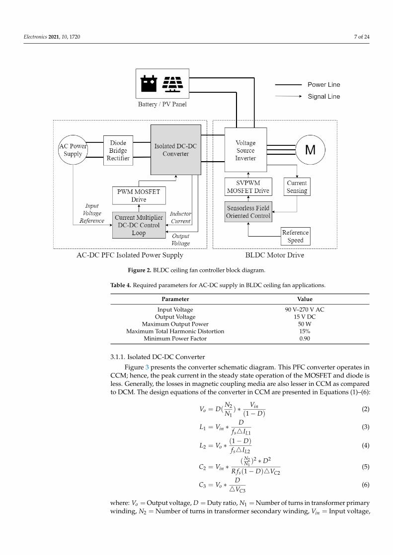
This section presents the design methodology of the integrated magnetics isolatedCuk converter supply for the specific application of BLDC ceiling fans. The motor driverand sensorless speed control have been used to drive the fan at the rated speed and torque.Figure 2 depicts a complete block diagram of the system design. It includes two mainblocks, namely the AC-DC PFC isolated power supply and the BLDC motor drive. Theformer block provides stable power supply with nearly zero current ripples, while thelatter block spins the motor efficiently. Each block is explained in detail below.
3.1. AC-DC PFC Isolated Power Supply
The fundamental objective of the AC-DC PFC isolated power supply is to provide astable DC supply of 15 V to the VSI in order to power the BLDC motor of the ceiling fan,improving power quality at the input AC supply and ensuring reliability by providingover-current protection. As illustrated in Figure 2, this block takes universal single-phaseAC voltage as the input, which is rectified by a full wave diode bridge rectifier. An isolatedCuk converter operating in CCM is then used for the DC-DC conversion. The converteris controlled by using an inner current loop and an outer voltage loop. The converter isdesigned to provide constant output voltage of 15 V, since the speed is controlled by FOCrather than varying the DC link voltage. Based on the common BLDC fan motors used forceiling fans, the required converter parameters at rated load are represented in Table 4.
Electronics 2021, 10, 1720 7 of 24
Figure 2. BLDC ceiling fan controller block diagram.
Table 4. Required parameters for AC-DC supply in BLDC ceiling fan applications.
Parameter Value
Input Voltage 90 V–270 V ACOutput Voltage 15 V DC
Maximum Output Power 50 WMaximum Total Harmonic Distortion 15%
Minimum Power Factor 0.90
3.1.1. Isolated DC-DC Converter
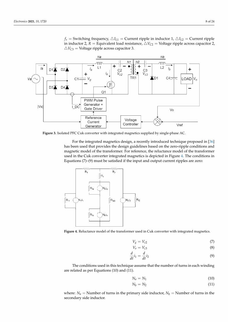
Figure 3 presents the converter schematic diagram. This PFC converter operates inCCM; hence, the peak current in the steady state operation of the MOSFET and diode isless. Generally, the losses in magnetic coupling media are also lesser in CCM as comparedto DCM. The design equations of the converter in CCM are presented in Equations (1)–(6):
Vo = D(N2
N1) ∗ Vin
(1− D)(2)
L1 = Vin ∗D
fs4IL1(3)
L2 = Vo ∗(1− D)
fs4IL2(4)
C2 = Vin ∗(N2
N1)2 ∗ D2
R fs(1− D)4VC2(5)
C3 = Vo ∗D4VC3
(6)
where: Vo = Output voltage, D = Duty ratio, N1 = Number of turns in transformer primarywinding, N2 = Number of turns in transformer secondary winding, Vin = Input voltage,
Electronics 2021, 10, 1720 8 of 24
fs = Switching frequency, 4IL1 = Current ripple in inductor 1, 4IL2 = Current ripplein inductor 2, R = Equivalent load resistance, 4VC2 = Voltage ripple across capacitor 2,4VC3 = Voltage ripple across capacitor 3.
Figure 3. Isolated PFC Cuk converter with integrated magnetics supplied by single-phase AC.
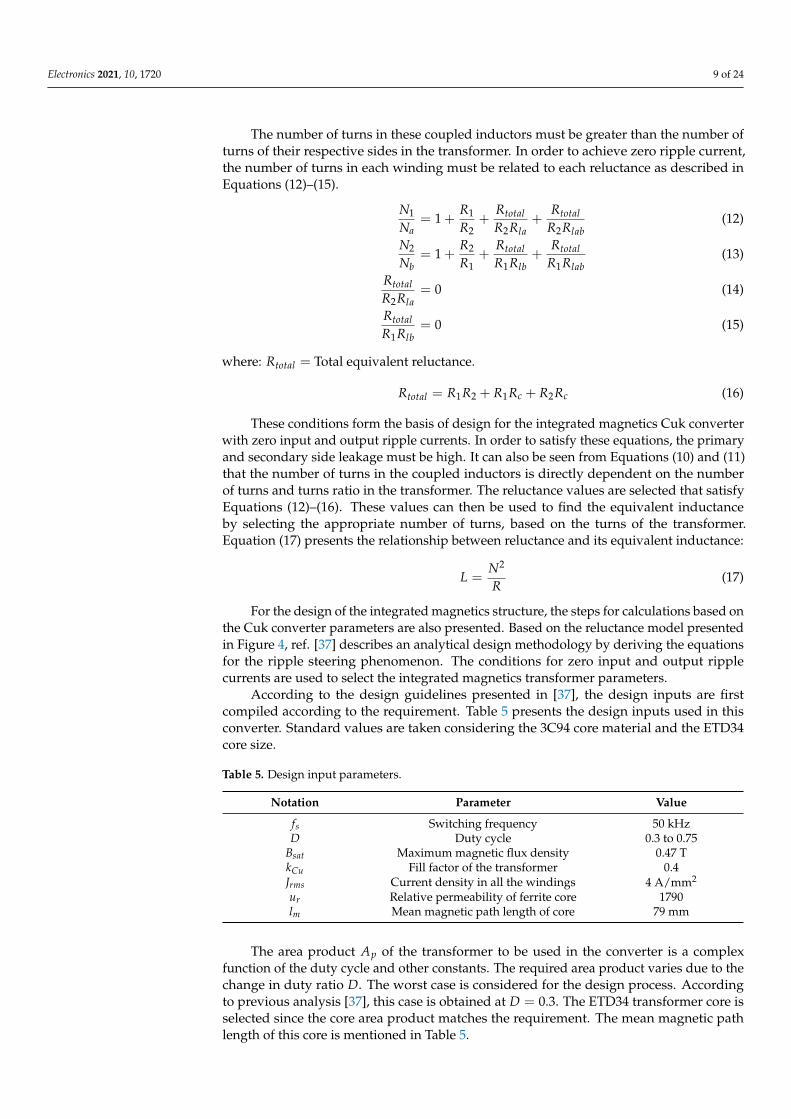
For the integrated magnetics design, a recently introduced technique proposed in [36]has been used that provides the design guidelines based on the zero-ripple conditions andmagnetic model of the transformer. For reference, the reluctance model of the transformerused in the Cuk converter integrated magnetics is depicted in Figure 4. The conditions inEquations (7)–(9) must be satisfied if the input and output current ripples are zero:
Figure 4. Reluctance model of the transformer used in Cuk converter with integrated magnetics.
Vg = Vc2 (7)
Vo = Vc3 (8)ddt
i1 =ddt
i2 (9)
The conditions used in this technique assume that the number of turns in each windingare related as per Equations (10) and (11).
Na = N1 (10)
Nb = N2 (11)
where: Na = Number of turns in the primary side inductor, Nb = Number of turns in thesecondary side inductor.
Electronics 2021, 10, 1720 9 of 24
The number of turns in these coupled inductors must be greater than the number ofturns of their respective sides in the transformer. In order to achieve zero ripple current,the number of turns in each winding must be related to each reluctance as described inEquations (12)–(15).
N1
Na= 1 +
R1
R2+
RtotalR2Rla
+Rtotal
R2Rlab(12)
N2
Nb= 1 +
R2
R1+
RtotalR1Rlb
+Rtotal
R1Rlab(13)
RtotalR2Rla
= 0 (14)
RtotalR1Rlb
= 0 (15)
where: Rtotal = Total equivalent reluctance.
Rtotal = R1R2 + R1Rc + R2Rc (16)
These conditions form the basis of design for the integrated magnetics Cuk converterwith zero input and output ripple currents. In order to satisfy these equations, the primaryand secondary side leakage must be high. It can also be seen from Equations (10) and (11)that the number of turns in the coupled inductors is directly dependent on the numberof turns and turns ratio in the transformer. The reluctance values are selected that satisfyEquations (12)–(16). These values can then be used to find the equivalent inductanceby selecting the appropriate number of turns, based on the turns of the transformer.Equation (17) presents the relationship between reluctance and its equivalent inductance:
L =N2
R(17)
For the design of the integrated magnetics structure, the steps for calculations based onthe Cuk converter parameters are also presented. Based on the reluctance model presentedin Figure 4, ref. [37] describes an analytical design methodology by deriving the equationsfor the ripple steering phenomenon. The conditions for zero input and output ripplecurrents are used to select the integrated magnetics transformer parameters.
According to the design guidelines presented in [37], the design inputs are firstcompiled according to the requirement. Table 5 presents the design inputs used in thisconverter. Standard values are taken considering the 3C94 core material and the ETD34core size.
Table 5. Design input parameters.
Notation Parameter Value
fs Switching frequency 50 kHzD Duty cycle 0.3 to 0.75
Bsat Maximum magnetic flux density 0.47 TkCu Fill factor of the transformer 0.4Jrms Current density in all the windings 4 A/mm2
ur Relative permeability of ferrite core 1790lm Mean magnetic path length of core 79 mm
The area product Ap of the transformer to be used in the converter is a complexfunction of the duty cycle and other constants. The required area product varies due to thechange in duty ratio D. The worst case is considered for the design process. Accordingto previous analysis [37], this case is obtained at D = 0.3. The ETD34 transformer core isselected since the core area product matches the requirement. The mean magnetic pathlength of this core is mentioned in Table 5.
Electronics 2021, 10, 1720 10 of 24
The next step in the design methodology is to calculate the number of turns in theprimary winding of the transformer, referred to as N1 in the manuscript. The formula inEquation (18) can be used for this calculation. Here, the value of magnetizing inductanceL1 and magnetizing current IM is determined by the input source characteristics, while thevalues of Bsat and Ac are based on the core material and size.
N1 =L1 IM
Bsat Ac(18)
After the determination of N1, the next step is to calculate the air gap, which is givenby Equation (19). The parameters lm and ur are also dependent on the core material andsize. The values for ETD34 and 3C94 material are mentioned in Table 5.
g =N1
2uo Ac
2Lp− lm
2ur(19)
Based on the above formulae, Table 6 is formulated, which consists of the outputdesign parameters. These parameters are used to design the integrated magnetics structurefor the converter.
Table 6. Converter design parameters.
Notation Parameter Value
N1 Number of turns in transformer primary winding 55N2 Number of turns in transformer secondary winding 7Na Number of turns in primary inductor winding 55Nb Number of turns in secondary inductor winding 7g Air gap in the transformer core 1.1 mm
3.1.2. Current Multiplier DC-DC Control Loop
Figure 3 illustrates the schematic diagram of the converter along with the controlblocks required to implement the current multiplier approach for power quality improve-ment. The Cuk converter is supplied by a full bridge rectifier. The switching frequency( fs) of the Cuk converter is selected as 50 kHz. In order to improve the power quality, theinput supply current should be in phase with supply voltage. The converter is operatedin CCM. The PFC control scheme employs the use of the current multiplier approachwith a current control loop inside the voltage control loop. The control loop calculatesthe voltage error (Ve), obtained after comparing the output voltage of the converter (Vo)with the reference voltage (Vre f ), which is equivalent to the rated voltage of the fan motor.A proportional–integral (PI) controller is used to give the control signal (Ic). This signal(Ic) is multiplied with a unit reference of the input AC voltage to obtain the reference DCcurrent (Id−re f ) and compared with the DC current (Id) sensed through the diode bridgerectifier. The resultant current error (Ie) is amplified and compared with a sawtooth carrierwave of fixed frequency ( fs) to generate the pulse width modulation (PWM) pulse for theCuk converter. The duty cycle (D) of the PWM signal of switching frequency ( fs) regulatesthe output voltage at the setpoint (reference value). The current loop in the converteralso provides over-current protection and hence prevents failure in case the fan motor isoverloaded or stalled due to mechanical shortcomings, leading to a reliable design.
3.2. BLDC Motor Drive
The second main block is the BLDC motor drive. The isolated Cuk converter suppliespower at constant voltage to the VSI. It is a conventional three-phase bridge with low andhigh side MOSFETs. The low side MOSFETs are driven directly whereas the high sideMOSFETs are driven by means of a bootstrap supply. The FOC algorithm requires thecurrent feedback from each of the three phases. The single-shunt topology is used to sensethe VSI current. A single-shunt resistance which is common to all three arms of the bridge
Electronics 2021, 10, 1720 11 of 24
is connected to measure the current being drawn by the three phase bridge. By measuringthe voltage across this shunt resistance, the phase currents are reconstructed and used bythe FOC algorithm to estimate the rotor position. This voltage drop across the shunt isamplified with a non-inverting amplifier and read by the analog to digital converter (ADC)in the microcontroller running the algorithm. The shunt resistor value and amplifier gainare designed so that the maximum current flow through the bridge corresponds with themaximum current limit of the ceiling fan BLDC motor.
This single-shunt topology has been preferred over the three-shunt variant. Thisreduces the hardware complexity since only one shunt and one signal conditioning am-plifier are required. This option is feasible if the computing power is available to performthe mathematical calculations required for phase current reconstruction. The three-shuntconfiguration, on the other hand, requires three shunts and three signal conditioningamplifiers, but it eliminates the need for mathematical calculations required for phasecurrent reconstruction.
Sensorless Field Oriented Control
The speed control mechanism is an important consideration of the ceiling fan drive.The fan speed has an exponential relationship with the power consumption. In order tooptimize the fan’s power consumption, the fan speed must be controlled to achieve a goodcompromise between the air flow produced by the fan and the power consumed. Thus,the ceiling fan drive should be able to support these variations in speed smoothly. FOCprovides a speed control mechanism that can vary the fan speed smoothly even at differentDC link voltages of the VSI. This is particularly useful if the VSI is supplied by a DC voltagesource that is not fixed at a constant level; hence, the drive circuit can withstand variationsin the DC link voltage of the VSI.
The motor is ramped up in open loop with current control until it reaches a substantialspeed, and then the algorithm can be switched from open to closed loop. The final speed ofthe ramp is set to 30% of the maximum rotor speed and current is set to 50% of the motornominal current. These startup parameters are experimentally tested and then refined toensure smooth ramp up and transition to the closed loop FOC algorithm. Once the motorcontroller is in closed loop, the desired speed is set by providing the torque reference.This torque reference is compared with the measured value, and then the motor speed isadjusted by the FOC algorithm to match the reference torque. This reference is the maincontrol parameter that can be set either by the IR remote control or an external Internet-connected microcontroller as illustrated in Figure 2. In order to obtain high resolution ofspeed steps/settings, this reference is incremented or decremented slightly and graduallydepending on whether the speed needs to be increased or decreased. In order to drive theBLDC motor, the two current components at D and Q axis are controlled. In order to obtainmaximum torque from the motor, the D-axis current Id is set to zero, whereas the Q-axiscurrent represented by Iq is set as per the required speed and torque.
With this method, the speed can be controlled even when the motor is powered byan alternative DC power source in case the utility electricity supply is unavailable. TheVSI may also be supplied by an external DC power source such as PV panels. In this case,the DC link voltage of the inverter will not be supplied by the isolated Cuk converter. Abattery or a PV panel may be used directly to supply the DC link voltage. The limitation ofusing these alternative sources is that the VSI will not be supplied by a constant voltage,given the intermittent nature of output voltage of a PV panel and the voltage variations ofa battery based on its state of charge. These variations can effect the speed of the BLDCmotor by changing the magnitude of current through the motor windings. The advantageof using FOC here is that these variations can be accounted for by observing the feedbackfrom the VSI and adjusting the fan speed accordingly. The motor flux linkage and hencetorque depend on the phase current that can be controlled by the DC link voltage andfundamental switching frequency. Therefore, a positive difference in the DC link voltagecan be accounted for by introducing a negative change in the fundamental frequency and
Electronics 2021, 10, 1720 12 of 24
vice versa. This allows for constant speed regulation even with a supply that exhibitsvariations in DC voltage levels.
4. System Performance Validation
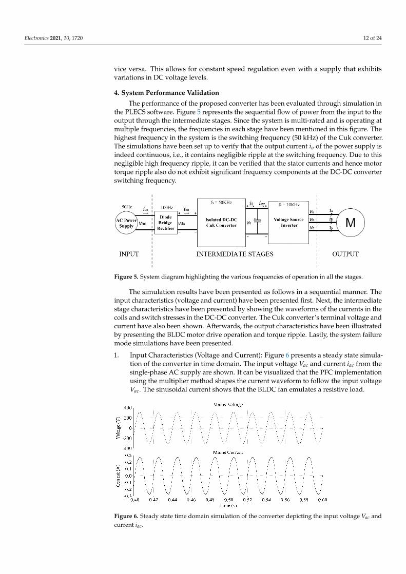
The performance of the proposed converter has been evaluated through simulation inthe PLECS software. Figure 5 represents the sequential flow of power from the input to theoutput through the intermediate stages. Since the system is multi-rated and is operating atmultiple frequencies, the frequencies in each stage have been mentioned in this figure. Thehighest frequency in the system is the switching frequency (50 kHz) of the Cuk converter.The simulations have been set up to verify that the output current io of the power supply isindeed continuous, i.e., it contains negligible ripple at the switching frequency. Due to thisnegligible high frequency ripple, it can be verified that the stator currents and hence motortorque ripple also do not exhibit significant frequency components at the DC-DC converterswitching frequency.
Figure 5. System diagram highlighting the various frequencies of operation in all the stages.
The simulation results have been presented as follows in a sequential manner. Theinput characteristics (voltage and current) have been presented first. Next, the intermediatestage characteristics have been presented by showing the waveforms of the currents in thecoils and switch stresses in the DC-DC converter. The Cuk converter’s terminal voltage andcurrent have also been shown. Afterwards, the output characteristics have been illustratedby presenting the BLDC motor drive operation and torque ripple. Lastly, the system failuremode simulations have been presented.
1. Input Characteristics (Voltage and Current): Figure 6 presents a steady state simula-tion of the converter in time domain. The input voltage Vac and current iac from thesingle-phase AC supply are shown. It can be visualized that the PFC implementationusing the multiplier method shapes the current waveform to follow the input voltageVac. The sinusoidal current shows that the BLDC fan emulates a resistive load.
Figure 6. Steady state time domain simulation of the converter depicting the input voltage Vac andcurrent iac.
Electronics 2021, 10, 1720 13 of 24
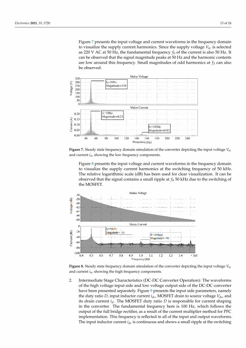
Figure 7 presents the input voltage and current waveforms in the frequency domainto visualize the supply current harmonics. Since the supply voltage Vac is selectedas 220 V AC at 50 Hz, the fundamental frequency f0 of the current is also 50 Hz. Itcan be observed that the signal magnitude peaks at 50 Hz and the harmonic contentsare low around this frequency. Small magnitudes of odd harmonics at f3 can alsobe observed.
Figure 7. Steady state frequency domain simulation of the converter depicting the input voltage Vac
and current iac showing the low frequency components.
Figure 8 presents the input voltage and current waveforms in the frequency domainto visualize the supply current harmonics at the switching frequency of 50 kHz.The relative logarithmic scale (dB) has been used for clear visualization. It can beobserved that the signal contains a small ripple at f0 50 kHz due to the switching ofthe MOSFET.
Figure 8. Steady state frequency domain simulation of the converter depicting the input voltage Vac
and current iac showing the high frequency components.
2. Intermediate Stage Characteristics (DC-DC Converter Operation): The waveformsof the high voltage input side and low voltage output side of the DC-DC converterhave been presented separately. Figure 9 presents the input side parameters, namelythe duty ratio D, input inductor current idc, MOSFET drain to source voltage Vds, andits drain current id. The MOSFET duty ratio D is responsible for current shapingin the converter. The fundamental frequency here is 100 Hz, which follows theoutput of the full bridge rectifier, as a result of the current multiplier method for PFCimplementation. This frequency is reflected in all of the input and output waveforms.The input inductor current idc is continuous and shows a small ripple at the switching
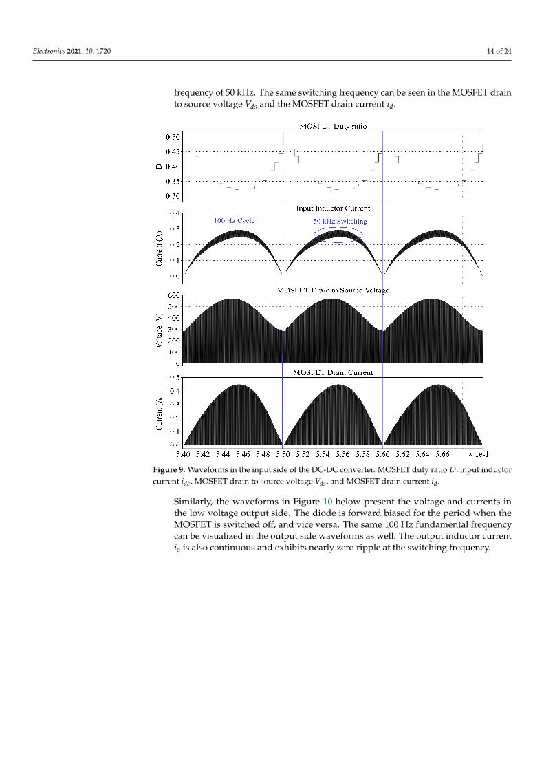
Electronics 2021, 10, 1720 14 of 24
frequency of 50 kHz. The same switching frequency can be seen in the MOSFET drainto source voltage Vds and the MOSFET drain current id.
Figure 9. Waveforms in the input side of the DC-DC converter. MOSFET duty ratio D, input inductorcurrent idc, MOSFET drain to source voltage Vds, and MOSFET drain current id.
Similarly, the waveforms in Figure 10 below present the voltage and currents inthe low voltage output side. The diode is forward biased for the period when theMOSFET is switched off, and vice versa. The same 100 Hz fundamental frequencycan be visualized in the output side waveforms as well. The output inductor currentio is also continuous and exhibits nearly zero ripple at the switching frequency.

Electronics 2021, 10, 1720 15 of 24
Figure 10. Waveforms in the output side of the DC-DC converter: output inductor current io, diodevoltage Vdiode, and diode current idiode.
Figure 11 presents the output voltage Vo and output inductor current io of the pro-posed converter. Initially, the current magnitude is high because the DC link capacitorneeds to be charged. When the output voltage Vo becomes stable at 15 V, the motorramps up and reaches steady state. It can be noted, however, that the output voltageVo increases slightly in the time range 0.14–0.22 s. This increase is due to the initialovershoot of the converter’s control system. After this slight overshoot, the outputvoltage settles at 15 V, which is the reference setpoint of the output voltage. Thecurrent magnitude is constant when this steady state is reached. It can be noted,however, that the output inductor current io oscillates at 100 Hz, due to the absenceof a DC bulk capacitor at the output terminals Vdc of the diode bridge rectifier. This isan inherent characteristic of the PFC technique used [38]. Since the FOC loop of thesensorless BLDC motor control operates at 10 kHz, this low frequency oscillation doesnot cause significant ripple in either the stator currents iabc or the motor torque Te.
Figure 11. Time domain simulation of the converter depicting the output voltage Vo and outputinductor current io.
Electronics 2021, 10, 1720 16 of 24
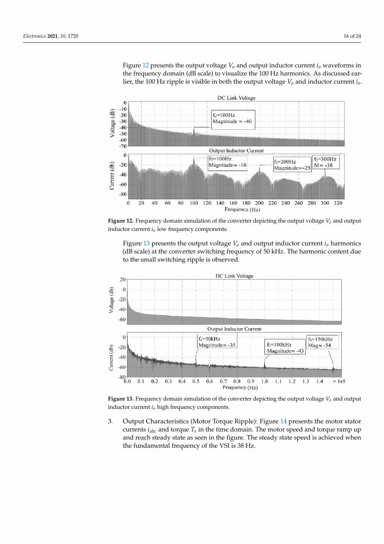
Figure 12 presents the output voltage Vo and output inductor current io waveforms inthe frequency domain (dB scale) to visualize the 100 Hz harmonics. As discussed ear-lier, the 100 Hz ripple is visible in both the output voltage Vo and inductor current io.
Figure 12. Frequency domain simulation of the converter depicting the output voltage Vo and outputinductor current io low frequency components.
Figure 13 presents the output voltage Vo and output inductor current io harmonics(dB scale) at the converter switching frequency of 50 kHz. The harmonic content dueto the small switching ripple is observed.
Figure 13. Frequency domain simulation of the converter depicting the output voltage Vo and outputinductor current io high frequency components.
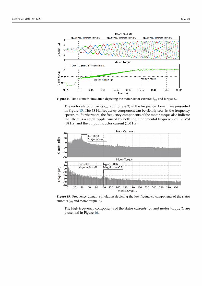
3. Output Characteristics (Motor Torque Ripple): Figure 14 presents the motor statorcurrents iabc and torque Te in the time domain. The motor speed and torque ramp upand reach steady state as seen in the figure. The steady state speed is achieved whenthe fundamental frequency of the VSI is 38 Hz.
Electronics 2021, 10, 1720 17 of 24
Figure 14. Time domain simulation depicting the motor stator currents iabc and torque Te.
The motor stator currents iabc and torque Te in the frequency domain are presentedin Figure 15. The 38 Hz frequency component can be clearly seen in the frequencyspectrum. Furthermore, the frequency components of the motor torque also indicatethat there is a small ripple caused by both the fundamental frequency of the VSI(38 Hz) and the output inductor current (100 Hz).
Figure 15. Frequency domain simulation depicting the low frequency components of the statorcurrents iabc and motor torque Te.
The high frequency components of the stator currents iabc and motor torque Te arepresented in Figure 16.
Electronics 2021, 10, 1720 18 of 24
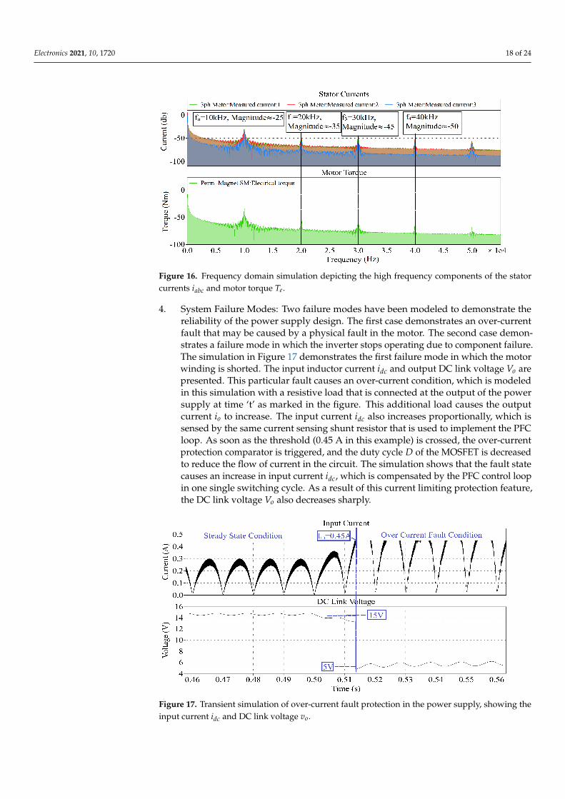
Figure 16. Frequency domain simulation depicting the high frequency components of the statorcurrents iabc and motor torque Te.
4. System Failure Modes: Two failure modes have been modeled to demonstrate thereliability of the power supply design. The first case demonstrates an over-currentfault that may be caused by a physical fault in the motor. The second case demon-strates a failure mode in which the inverter stops operating due to component failure.The simulation in Figure 17 demonstrates the first failure mode in which the motorwinding is shorted. The input inductor current idc and output DC link voltage Vo arepresented. This particular fault causes an over-current condition, which is modeledin this simulation with a resistive load that is connected at the output of the powersupply at time ‘t’ as marked in the figure. This additional load causes the outputcurrent io to increase. The input current idc also increases proportionally, which issensed by the same current sensing shunt resistor that is used to implement the PFCloop. As soon as the threshold (0.45 A in this example) is crossed, the over-currentprotection comparator is triggered, and the duty cycle D of the MOSFET is decreasedto reduce the flow of current in the circuit. The simulation shows that the fault statecauses an increase in input current idc, which is compensated by the PFC control loopin one single switching cycle. As a result of this current limiting protection feature,the DC link voltage Vo also decreases sharply.
Figure 17. Transient simulation of over-current fault protection in the power supply, showing theinput current idc and DC link voltage vo.
Electronics 2021, 10, 1720 19 of 24
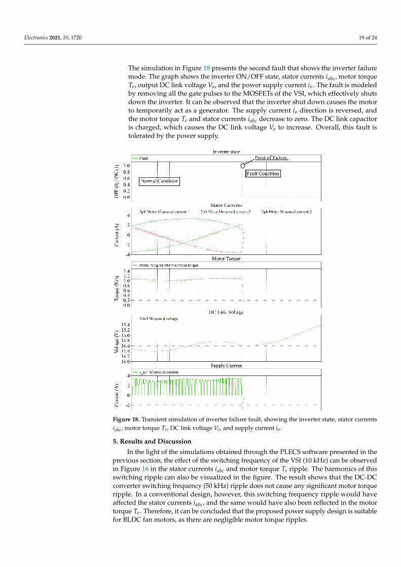
The simulation in Figure 18 presents the second fault that shows the inverter failuremode. The graph shows the inverter ON/OFF state, stator currents iabc, motor torqueTe, output DC link voltage Vo, and the power supply current io. The fault is modeledby removing all the gate pulses to the MOSFETs of the VSI, which effectively shutsdown the inverter. It can be observed that the inverter shut down causes the motorto temporarily act as a generator. The supply current io direction is reversed, andthe motor torque Te and stator currents iabc decrease to zero. The DC link capacitoris charged, which causes the DC link voltage Vo to increase. Overall, this fault istolerated by the power supply.
Figure 18. Transient simulation of inverter failure fault, showing the inverter state, stator currentsiabc, motor torque Te, DC link voltage Vo, and supply current io.
5. Results and Discussion
In the light of the simulations obtained through the PLECS software presented in theprevious section, the effect of the switching frequency of the VSI (10 kHz) can be observedin Figure 16 in the stator currents iabc and motor torque Te ripple. The harmonics of thisswitching ripple can also be visualized in the figure. The result shows that the DC-DCconverter switching frequency (50 kHz) ripple does not cause any significant motor torqueripple. In a conventional design, however, this switching frequency ripple would haveaffected the stator currents iabc, and the same would have also been reflected in the motortorque Te. Therefore, it can be concluded that the proposed power supply design is suitablefor BLDC fan motors, as there are negligible motor torque ripples.
Electronics 2021, 10, 1720 20 of 24
In view of the failure modes analysis presented in the above section, the power supplytolerates over-current faults by limiting the input current idc of the converter, as seen inFigure 17. The value of the MOSFET duty cycle D is updated at the switching frequencyfs = 50 kHz according to the current and voltage feedback. Therefore, in the case of anover-current event, the response time of the loop will be one switching interval of theDC-DC converter. In this case, Ts = 20 µs. As a result of this current limiting protectionfeature, the DC link voltage Vo also decreases sharply. Moreover, as shown in Figure 18,the converter also tolerates inverter failure without causing any damage. Therefore, it canbe concluded that the two common faults discussed in this paper do not negatively affectthe system, making it reliable.
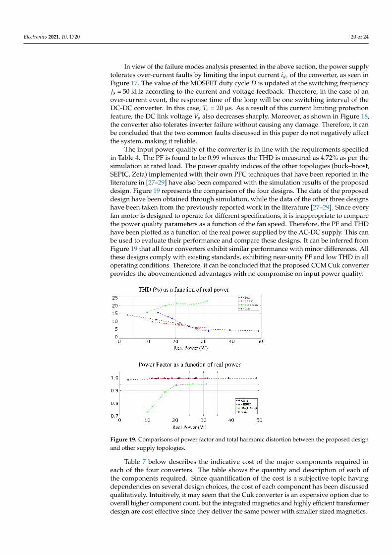
The input power quality of the converter is in line with the requirements specifiedin Table 4. The PF is found to be 0.99 whereas the THD is measured as 4.72% as per thesimulation at rated load. The power quality indices of the other topologies (buck–boost,SEPIC, Zeta) implemented with their own PFC techniques that have been reported in theliterature in [27–29] have also been compared with the simulation results of the proposeddesign. Figure 19 represents the comparison of the four designs. The data of the proposeddesign have been obtained through simulation, while the data of the other three designshave been taken from the previously reported work in the literature [27–29]. Since everyfan motor is designed to operate for different specifications, it is inappropriate to comparethe power quality parameters as a function of the fan speed. Therefore, the PF and THDhave been plotted as a function of the real power supplied by the AC-DC supply. This canbe used to evaluate their performance and compare these designs. It can be inferred fromFigure 19 that all four converters exhibit similar performance with minor differences. Allthese designs comply with existing standards, exhibiting near-unity PF and low THD in alloperating conditions. Therefore, it can be concluded that the proposed CCM Cuk converterprovides the abovementioned advantages with no compromise on input power quality.
Figure 19. Comparisons of power factor and total harmonic distortion between the proposed designand other supply topologies.
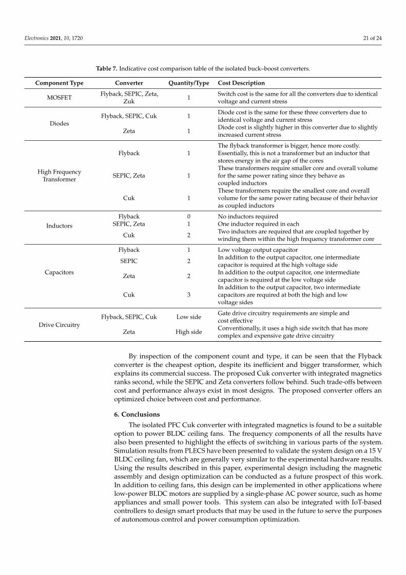
Table 7 below describes the indicative cost of the major components required ineach of the four converters. The table shows the quantity and description of each ofthe components required. Since quantification of the cost is a subjective topic havingdependencies on several design choices, the cost of each component has been discussedqualitatively. Intuitively, it may seem that the Cuk converter is an expensive option due tooverall higher component count, but the integrated magnetics and highly efficient transformerdesign are cost effective since they deliver the same power with smaller sized magnetics.
Electronics 2021, 10, 1720 21 of 24
Table 7. Indicative cost comparison table of the isolated buck–boost converters.
Component Type Converter Quantity/Type Cost Description
MOSFET Flyback, SEPIC, Zeta,Zuk 1 Switch cost is the same for all the converters due to identical
voltage and current stress
DiodesFlyback, SEPIC, Cuk 1 Diode cost is the same for these three converters due to
identical voltage and current stress
Zeta 1 Diode cost is slightly higher in this converter due to slightlyincreased current stress
Flyback 1The flyback transformer is bigger, hence more costly.Essentially, this is not a transformer but an inductor thatstores energy in the air gap of the cores
High FrequencyTransformer SEPIC, Zeta 1
These transformers require smaller core and overall volumefor the same power rating since they behave ascoupled inductors
Cuk 1These transformers require the smallest core and overallvolume for the same power rating because of their behavioras coupled inductors
Flyback 0 No inductors requiredInductors SEPIC, Zeta 1 One inductor required in each
Cuk 2 Two inductors are required that are coupled together bywinding them within the high frequency transformer core
Flyback 1 Low voltage output capacitor
Capacitors
SEPIC 2 In addition to the output capacitor, one intermediatecapacitor is required at the high voltage side
Zeta 2 In addition to the output capacitor, one intermediatecapacitor is required at the low voltage side
Cuk 3In addition to the output capacitor, two intermediatecapacitors are required at both the high and lowvoltage sides
Drive CircuitryFlyback, SEPIC, Cuk Low side Gate drive circuitry requirements are simple and
cost effective
Zeta High side Conventionally, it uses a high side switch that has morecomplex and expensive gate drive circuitry
By inspection of the component count and type, it can be seen that the Flybackconverter is the cheapest option, despite its inefficient and bigger transformer, whichexplains its commercial success. The proposed Cuk converter with integrated magneticsranks second, while the SEPIC and Zeta converters follow behind. Such trade-offs betweencost and performance always exist in most designs. The proposed converter offers anoptimized choice between cost and performance.
6. Conclusions
The isolated PFC Cuk converter with integrated magnetics is found to be a suitableoption to power BLDC ceiling fans. The frequency components of all the results havealso been presented to highlight the effects of switching in various parts of the system.Simulation results from PLECS have been presented to validate the system design on a 15 VBLDC ceiling fan, which are generally very similar to the experimental hardware results.Using the results described in this paper, experimental design including the magneticassembly and design optimization can be conducted as a future prospect of this work.In addition to ceiling fans, this design can be implemented in other applications wherelow-power BLDC motors are supplied by a single-phase AC power source, such as homeappliances and small power tools. This system can also be integrated with IoT-basedcontrollers to design smart products that may be used in the future to serve the purposesof autonomous control and power consumption optimization.

Electronics 2021, 10, 1720 22 of 24
Author Contributions: Conceptualization, H.R.K. and S.A.Q.; methodology, H.R.K., H.B.A. andM.H.B.K.; software, H.B.A. and M.H.B.K.; validation, H.R.K., M.K. and S.A.Q.; formal analysis,H.B.A., M.K. and M.H.B.K.; investigation, M.K. and H.B.A.; resources, A.H. and S.A.Q.; data curation,H.B.A., M.H.B.K. and A.H.; writing—original draft preparation, H.B.A.; writing—review and editing,M.K. and S.A.Q.; visualization, H.R.K., M.K., H.B.A., M.H.B.K. and A.H.; supervision, H.R.K.; projectadministration, S.A.Q.; funding acquisition, S.A.Q. All authors have read and agreed to the publishedversion of the manuscript.
Funding: This work is funded by Neuro-computation Lab, National Center of Artificial Intelligence,NED University of Engineering and Technology, Pakistan.
Data Availability Statement: The data presented in this study are available in this article.
Conflicts of Interest: The authors declare no conflict of interest. The funders had no role in the designof the study; in the collection, analyses, or interpretation of data; in the writing of the manuscript; orin the decision to publish the results.
Appendix A
Table A1. List of acronyms.
Acronym Full Term
ADC Analog to Digital ConverterCCM Continuous Conduction ModeCRT Cathode Ray TubeDCM Discontinuous Conduction ModeEMF Electro Motive ForceFOC Field Oriented ControlPF Power Factor
PFC Power Factor CorrectionPLECS Piecewise Linear Electrical Circuit SimulationPMSM Permanent Magnet Synchronous Motor
PV Photo-VoltaicPWM Pulse Width ModulationSEPIC Single Ended Primary Inductance ConverterTHD Total Harmonic DistortionVSI Voltage Source Inverter
Table A2. List of notations and their units.
Notation Full Term Unit
Vo Output voltage VD Duty ratio -N1 Number of turns in transformer primary winding -N2 Number of turns in transformer secondary winding -Vin Input voltage Vfs Switching frequency Hz4IL1 Current ripple in inductor 1 A4IL2 Current ripple in inductor 2 A
R Equivalent load resistance Ohms4VC2 Voltage ripple across capacitor 2 V4VC3 Voltage ripple across capacitor 3 V
Na Number of turns in the primary side inductor -Nb Number of turns in the secondary side inductor -
Rtotal Total equivalent reluctance AT/WebVe Voltage error V
Vre f Reference voltage VId D-axis current AIq Q-axis current A
Electronics 2021, 10, 1720 23 of 24
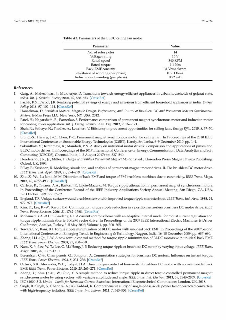
Table A3. Parameters of the BLDC ceiling fan motor.
Parameter Value
No. of rotor poles 14Voltage rating 15 VRated speed 340 RPMRated torque 1.1 Nm
Back-EMF constant 31 Vrms/krpmResistance of winding (per phase) 0.55 OhmsInductance of winding (per phase) 0.72 mH
References1. Garg, A.; Maheshwari, J.; Mukherjee, D. Transitions towards energy-efficient appliances in urban households of gujarat state,
india. Int. J. Sustain. Energy 2020, 40, 638–653. [CrossRef]2. Parikh, K.S.; Parikh, J.K. Realizing potential savings of energy and emissions from efficient household appliances in india. Energy
Policy 2016, 97, 102–111. [CrossRef]3. Hanselman, D. Brushless Motors: Magnetic Design, Performance, and Control of Brushless DC and Permanent Magnet Synchronous
Motors; E-Man Press LLC: New York, NY, USA, 2012.4. Patel, H.; Nagarsheth, R.; Parnerkar, S. Performance comparison of permanent magnet synchronous motor and induction motor
for cooling tower application. Int. J. Emerg. Technol. Adv. Eng. 2012, 2, 167–171.5. Shah, N.; Sathaye, N.; Phadke, A.; Letschert, V. Efficiency improvement opportunities for ceiling fans. Energy Effic. 2015, 8, 37–50.
[CrossRef]6. Liu, C.-S.; Hwang, J.-C.; Chen, P.-C. Permanent magnet synchronous motor for ceiling fan. In Proceedings of the 2010 IEEE
International Conference on Sustainable Energy Technologies (ICSET), Kandy, Sri Lanka, 6–9 December 2010; pp. 1–4.7. Sakunthala, S.; Kiranmayi, R.; Mandadi, P.N. A study on industrial motor drives: Comparison and applications of pmsm and
BLDC motor drives. In Proceedings of the 2017 International Conference on Energy, Communication, Data Analytics and SoftComputing (ICECDS), Chennai, India, 1–2 August 2017; pp. 537–540.
8. Hendershot, J.R., Jr.; Miller, T. Design of Brushless Permanent Magnet Motor, 1st ed.; Clarendon Press/Magna Physics Publishing:Oxford, UK, 1994.
9. Pillay, P.; Krishnan, R. Modeling, simulation, and analysis of permanent-magnet motor drives. II. The brushless DC motor drive.IEEE Trans. Ind. Appl., 1989, 25, 274–279. [CrossRef]
10. Zhu, Z.; Wu, L.; Jamil, M.M. Distortion of back-EMF and torque of PM brushless machines due to eccentricity. IEEE Trans. Magn.2013, 49, 4927–4936. [CrossRef]
11. Carlson, R.; Tavares, A.A.; Bastos, J.P.; Lajoie-Mazenc, M. Torque ripple attenuation in permanent magnet synchronous motors.In Proceedings of the Conference Record of the IEEE Industry Applications Society Annual Meeting, San Diego, CA, USA,1–5 October 1989; pp. 57–62.
12. England, T.R. Unique surface-wound brushless servo with improved torque ripple characteristics. IEEE Trans. Ind. Appl. 1988, 24,972–977. [CrossRef]
13. Kim, D.; Lee, K.-W.; Kwon, B.-I. Commutation torque ripple reduction in a position sensorless brushless DC motor drive. IEEETrans. Power Electron. 2006, 21, 1762–1768. [CrossRef]
14. Mohamed, Y.A.-R.I.; El-Saadany, E.F. A current control scheme with an adaptive internal model for robust current regulation andtorque ripple minimization in PMSM vector drive. In Proceedings of the 2007 IEEE International Electric Machines & DrivesConference, Antalya, Turkey, 3–5 May 2007; Volume 1, pp. 300–305.
15. Tewari, S.V.; Rani, B.I. Torque ripple minimization of BLDC motor with un-ideal back EMF. In Proceedings of the 2009 SecondInternational Conference on Emerging Trends in Engineering & Technology, Nagpur, India, 16–18 December 2009; pp. 687–690.
16. Zhang, H.L.; Qu, L.W. A new torque control method for torque ripple minimization of BLDC motors with un-ideal back EMF.IEEE Trans. Power Electron. 2008, 23, 950–958.
17. Nam, K.-Y.; Lee, W.-T.; Lee, C.-M.; Hong, J.-P. Reducing torque ripple of brushless DC motor by varying input voltage. IEEE Trans.Magn. 2006, 42, 1307–1310.
18. Berendsen, C.-S.; Champenois, G.; Bolopion, A. Commutation strategies for brushless DC motors: Influence on instant torque.IEEE Trans. Power Electron. 1993, 8, 231–236. [CrossRef]
19. Ozturk, S.B.; Alexander, W.C.; Toliyat, H.A. Direct torque control of four-switch brushless DC motor with non-sinusoidal backEMF. IEEE Trans. Power Electron. 2010, 25, 263–271. [CrossRef]
20. Zhang, Y.; Zhu, J.; Xu, W.; Guo, Y. A simple method to reduce torque ripple in direct torque-controlled permanent-magnetsynchronous motor by using vectors with variable amplitude and angle. IEEE Trans. Ind. Electron. 2011, 58, 2848–2859. [CrossRef]
21. IEC 61000-3-2. Limits—Limits for Harmonic Current Emissions; International Electrotechnical Commission: London, UK, 2018.22. Singh, B.; Singh, S.; Chandra, A.; Al-Haddad, K. Comprehensive study of single-phase ac-dc power factor corrected converters
with high-frequency isolation. IEEE Trans. Ind. Inform. 2011, 7, 540–556. [CrossRef]
Electronics 2021, 10, 1720 24 of 24
23. Bist, V.; Singh, B. A brushless dc motor drive with power factor correction using isolated zeta converter. IEEE Trans. Ind. Inform.2014, 10, 2064–2072. [CrossRef]
24. Bist, V.; Singh, B. Pfc cuk converter-fed BLDC motor drive. IEEE Trans. Power Electron. 2014, 30, 871–887. [CrossRef]25. Bist, V.; Singh, B. A unity power factor bridgeless isolated cuk converter-fed brushless dc motor drive. IEEE Trans. Ind. Electron.
2014, 62, 4118–4129. [CrossRef]26. Singh, P.K.; Singh, B.; Bist, V. Brushless dc motor drive with power factor regulation using landsman converter. IET Power Electron.
2016, 9, 900–910. [CrossRef]27. Manglik, S.; Sundeep, S.; Singh, B. Brushless dc motor based ceiling fan using buck-boost converter. In Proceedings of the 2016
IEEE 7th Power India International Conference (PIICON), Bikaner, India, 25–27 November 2016; pp. 1–6.28. Kumar, A.; Sharma, U.; Singh, B. Pmbldc motor based ceiling fan using an isolated pfc zeta converter. In Proceedings of the 2020
IEEE International Conference on Power Electronics, Smart Grid and Renewable Energy (PESGRE2020), Cochin, India, 2–4 January2020; pp. 1–6.
29. Kumar, A.; Sharma, U.; Singh, B. Bldc motor ceiling fan using a bridgeless isolated pfc sepic converter. In Proceedings of the 2020IEEE 9th Power India International Conference (PIICON), Sonepat, India, 28 February–1 March 2020; pp. 1–6.
30. Amirkhanian, H.; Oknaian, S. Power loss breakdown in bldc drives applications using matlab. In Proceedings of the InternationalExhibition and Conference for Power Electronics, Intelligent Motion, Renewable Energy and Energy Management, Nuremberg,Germany, 5–7 June 2018; pp. 1–5.
31. Infineon Technologies AG. Block Commutation vs. Foc in Power Tool Motor Control. Available online: https://www.infineon.com/dgdl/Infineon-Motor_power_tool_Block_Commutation_vs_FOC-ApplicationNotes-v01_00-EN.pdf?fileId=5546d4626eab8fbf016ed37fee474a65 (accessed on 4 January 2021).
32. Sasaki, H.; Asai, K.; Gohara, Y.; Moroizumi, M. Motor Control Circuit and Fan Including the Same. U.S. Patent 10,003,288, 19 June2018.
33. Huang, L.-Q.; Chang, Y.-C.; Liu, Y.-G.; Liang, Z.-J. Ceiling Fan, Method for Controlling Ceiling Fan Motor and Control Device forCeiling Fan Motor. U.S. Patent 10,374,536, 6 August 2019.
34. Rissetto, R.; Schweiker, M.; Wagner, A. Personalized ceiling fans: Effects of air motion, air direction and personal control onthermal comfort. Energy Build. 2021, 235, 110721. [CrossRef]
35. Williams, B.W. Transformer isolated buck-boost converters. Renew. Energy Sustain. Dev. 2016, 2, 112–125. [CrossRef]36. Ramanath, A.; Kshirsagar, A.; Thamballa, S.; Mohan, N. Equivalent Modeling, Design and Analysis of Integrated Magnetics Cuk
Converter. In Proceedings of the 2019 North American Power Symposium (NAPS), Wichita, KS, USA, 13–15 October 2019.37. Biswas, S.; Mohan, N.; Robbins, W. A systematic design method and verification for a zero-ripple interface for PV/Battery-to-grid
applications. In Proceedings of the 2016 IEEE Applied Power Electronics Conference and Exposition (APEC), Long Beach, CA,USA, 20–24 March 2016.
38. Singh, S.; Singh, B. A voltage-controlled pfc cuk converter-based pmbldcm drive for air-conditioners. IEEE Trans. Ind. Appl. 2012,48, 832–838. [CrossRef]