
An Introduction to the Event-B Modelling Method - Springer LINK
49
Appendix A An Introduction to the Event-B Modelling Method Thai Son Hoang Abstract This appendix is a short introduction to the Event-B modelling method for discrete transition systems. Important mechanisms for the step-wise development of formal models, such as context extension and machine refinement, are discussed. Consistency of the models is presented in terms of proof obligations and illustrated with concrete examples. A.1 Introduction Event-B [2] is a modelling method for formalising and developing systems whose components can be modelled as discrete transition systems. An evolution of the (classical) B-method [1], Event-B is now centred around the general notion of events, which are also found in other formal methods such as Action Systems [4], TLA [6] and UNITY [5]. Event-B models are organised in terms of two basic constructs: contexts and machines. Contexts specify the static part of a model, whereas machines specify the dynamic part. The role of the contexts is to isolate the parameters of a formal model and their properties, which are assumed to hold for all instances. A machine encapsulates a transition system with the state specified by a set of variables and transitions modelled by a set of guarded events. Event-B allows models to be developed gradually via mechanisms such as con- text extension and machine refinement. These techniques enable users to develop target systems from their abstract specifications, and subsequently introduce more implementation details. More importantly, properties that are proved at the abstract level are maintained through refinement, and hence are also guaranteed to be satis- fied by later refinements. As a result, correctness proofs of systems are broken down and distributed amongst different levels of abstraction, which is easier to manage. The rest of this appendix is structured as follows. We give a brief overview of the Event-B mathematical language in Sect. A.2. In Sect. A.3, we give an informal description of our running example. Subsequently, we show the basic constructs of T.S. Hoang (B ) Institute of Information Security, ETH Zurich, Zurich, Switzerland e-mail: [email protected] A. Romanovsky, M. Thomas (eds.), Industrial Deployment of System Engineering Methods, DOI 10.1007/978-3-642-33170-1, © Springer-Verlag Berlin Heidelberg 2013 211
-
Upload
khangminh22 -
Category
Documents
-
view
1 -
download
0
Transcript of An Introduction to the Event-B Modelling Method - Springer LINK

Appendix AAn Introduction to the Event-B ModellingMethod
Thai Son Hoang
Abstract This appendix is a short introduction to the Event-B modelling method fordiscrete transition systems. Important mechanisms for the step-wise developmentof formal models, such as context extension and machine refinement, are discussed.Consistency of the models is presented in terms of proof obligations and illustratedwith concrete examples.
A.1 Introduction
Event-B [2] is a modelling method for formalising and developing systems whosecomponents can be modelled as discrete transition systems. An evolution of the(classical) B-method [1], Event-B is now centred around the general notion ofevents, which are also found in other formal methods such as Action Systems [4],TLA [6] and UNITY [5].
Event-B models are organised in terms of two basic constructs: contexts andmachines. Contexts specify the static part of a model, whereas machines specifythe dynamic part. The role of the contexts is to isolate the parameters of a formalmodel and their properties, which are assumed to hold for all instances. A machineencapsulates a transition system with the state specified by a set of variables andtransitions modelled by a set of guarded events.
Event-B allows models to be developed gradually via mechanisms such as con-text extension and machine refinement. These techniques enable users to developtarget systems from their abstract specifications, and subsequently introduce moreimplementation details. More importantly, properties that are proved at the abstractlevel are maintained through refinement, and hence are also guaranteed to be satis-fied by later refinements. As a result, correctness proofs of systems are broken downand distributed amongst different levels of abstraction, which is easier to manage.
The rest of this appendix is structured as follows. We give a brief overview ofthe Event-B mathematical language in Sect. A.2. In Sect. A.3, we give an informaldescription of our running example. Subsequently, we show the basic constructs of
T.S. Hoang (B)Institute of Information Security, ETH Zurich, Zurich, Switzerlande-mail: [email protected]
A. Romanovsky, M. Thomas (eds.), Industrial Deployment of System EngineeringMethods, DOI 10.1007/978-3-642-33170-1,© Springer-Verlag Berlin Heidelberg 2013
211

212 T.S. Hoang
Table A.1 Definitions
Construct Definition
r ∈ S ↔ T r ∈ P(S × T)
f ∈ S �→ T f ∈ S ↔ T ∧ (∀x, y1, y2 ·x �→ y1 ∈ f ∧ x �→ y2 ∈ f ⇒ y1 = y2)
f ∈ S → T f ∈ S �→ T ∧ (∀x·x ∈ S ⇒ (∃y·x �→ y ∈ f ))
Event-B in Sects. A.4 (contexts) and A.5 (machines). We present the mechanismsfor context extension in Sect. A.6 and machine refinement in Sect. A.7.
A.2 The Event-B Mathematical Language
The basis for the formal models in Event-B is first-order logic and a typed set theory.We are not going to give full details of the Event-B logic here. For more informa-tion, we refer the reader to [2, 8]. We present several main elements of the Event-Bmathematical language that are important for understanding the Event-B models ofthe example below.
The first-order logic of Event-B contains standard operators such as conjunc-tion (∧), disjunction (∨), implication (⇒), negation (¬), equivalence (⇔), univer-sal quantification (∀), and existential quantification (∃). Two constants are defined,namely � and ⊥, denoting truth and falsity, respectively.
A.2.1 Set Theory
An important part of the mathematical language is its set-theoretical notation, withthe introduction of the membership predicate E ∈ S, meaning that expression Eis a member of set S. A set expression can be a variable (depending on its type).Moreover, a set can be explicitly defined by listing its members (set extension), e.g.{E1, . . . ,En}. Other basic set constructs include Cartesian product, power set, andset comprehension. Given two set expressions S and T , the Cartesian product of Sand T , denoted S × T , is the set of mappings (ordered pairs) x �→ y, where x ∈ S andy ∈ T . The power set of S, denoted P(S), is the set of all subsets of S. Finally, givena list of variables x, a predicate P constraining x and an expression E depending onx, the set comprehension {x·P | E} is the set of elements E where P holds.
A key feature of the Event-B set-theoretical notation is the models of relationsas sets of mappings. Different types of relations and functions are also defined assets of mappings with different additional properties. Given two set expressions Sand T , S ↔ T denotes the set of all binary relations from S to T . Similarly, S �→ Tdenotes the set of all partial functions from S to T , and S → T denotes the set of alltotal functions from S to T . Definitions of these relations can be seen in Table A.1,expressed using set memberships.

A An Introduction to the Event-B Modelling Method 213
Table A.2 Calculatingwell-definedness conditionsusing L
Formula Well-definedness condition
x �¬P L (P )
P ∧ Q L (P ) ∧ (P ⇒ L (Q))
∀x ·P ∀x ·L (P )
E1 ÷ E2 L (E1) ∧ L (E2) ∧ E2 �= 0
E1 ≤ E2 L (E1) ∧ L (E2)
card(E) L (E) ∧ finite(E)
f (E) L (E) ∧ f ∈ S �→ T ∧ E ∈ dom(f )
Intuitively, a binary relation r from S to T is a set of mappings x �→ y, wherex ∈ S and y ∈ T . A partial function f from S to T is a binary relation from S to T ,where each element x in S has at most one mapping to T . A total function f fromS to T is a partial function from S to T , where each element x in S has exactly onemapping to T .
A.2.2 Types
Variables in Event-B are strongly typed. A type in Event-B can be built-in (e.g.,BOOL, Z) or user-defined. Moreover, given types T , T1 and T2, the Cartesian prod-uct T1 × T2 and the power set P(T) are also types. In contrast with most stronglytyped programming languages, the types of variables in Event-B are not presentedwhen they are declared. Instead, they are inferred from constraining properties ofvariables. Typically, a property of the form x ∈ E, where E is of type P(T), allowsus to infer that x has type T .
A.2.3 Well-Definedness
Event-B requires every formula to be well defined [7, 8]. Informally, one has to provethat partial functions (either predefined, e.g. division ÷, or user-defined) are neverevaluated outside of their domain. Ill-defined expressions (such as x ÷ 0) shouldbe avoided. A syntactic operator L is used to map formulae to their correspond-ing well-definedness conditions. Table A.2 shows the definition of well-definednesscondition using L for formulae in Event-B. Here x is a variable, P and Q are pred-icates, E, E1, E2 are expressions, and f is a binary relation from S to T . Moreover,dom(f ) denotes the domain of f , i.e. the set of all elements in S that connect to anelement in T .
Notice that by using L , we assume a well-definedness order from left to right(e.g., for P ∧ Q) for formulae (this is similar to evaluating conditional statements,e.g. && or ||, in several programming languages).
214 T.S. Hoang
A.2.4 Sequents
Event-B defines proof obligations, which must be proved to show that formal mod-els fulfil their specified properties. Often these verification conditions are expressedin terms of sequents. A sequent H � G means that the goal G holds under theassumption of the set of hypotheses H . The obligations are discharged using cer-tain inference rules, which we will not describe here. Instead, we will give informaljustification of how proof obligations can be discharged. The purpose of presentingproof obligations within this appendix is to illustrate various conditions that need tobe proved to maintain the consistency of the example.
A.3 Example. A Course Management System
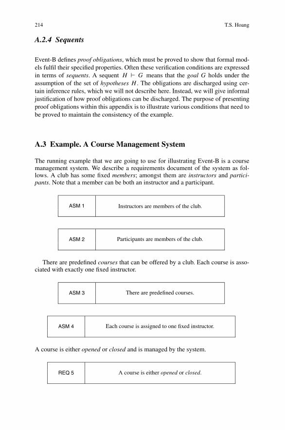
The running example that we are going to use for illustrating Event-B is a coursemanagement system. We describe a requirements document of the system as fol-lows. A club has some fixed members; amongst them are instructors and partici-pants. Note that a member can be both an instructor and a participant.
ASM 1 Instructors are members of the club.
ASM 2 Participants are members of the club.
There are predefined courses that can be offered by a club. Each course is asso-ciated with exactly one fixed instructor.
ASM 3 There are predefined courses.
ASM 4 Each course is assigned to one fixed instructor.
A course is either opened or closed and is managed by the system.
REQ 5 A course is either opened or closed.

A An Introduction to the Event-B Modelling Method 215
REQ 6 The system allows a closed course to be opened.
REQ 7 The system allows an opened course to be closed.
The number of opened courses is limited.
REQ 8The number of opened courses
cannot exceed a given limit.
Only when a course is opened, can participants register for the course. An impor-tant constraint for registration is that an instructor cannot attend his own courses.
REQ 9 Participants can only register for an opened course.
REQ 10 Instructors cannot attend their own courses.
In subsequent sections, we develop a formal model based on the above require-ments document. In particular, we will refer to the above requirements in order tojustify how they are formalised in the Event-B model.
A.4 Contexts
A context may contain carrier sets, constants, axioms, and theorems. Carrier sets areuser-defined types. By convention, a carrier set s is non-empty, i.e., satisfying s �= ∅,and maximal, i.e., satisfying ∀x·x ∈ s. Constants c denote static objects within thedevelopment.1 Axioms are presumed properties of carrier sets and constants. Theo-rems are derived properties of carrier sets and constants. Carrier sets and constantsmodel the parameters of development. Moreover, axioms state parameter proper-ties, assumed to hold for all their possible instances. A context C with carrier sets s,constants c, axioms A(s, c), and theorems T(s, c) can be presented as follows.
1When referring to carrier sets s and constants c, we usually allow for multiple carrier sets andconstants, i.e., they may be “vectors”.

216 T.S. Hoang
carrier sets: s constants: c
axioms:axm : A(s, c)thm : T(s, c)
Note that we present axioms and theorems using different labels, i.e., axm andthm. Later on, we also use different labels for other modelling elements, such asinvariants (inv), guards (grd) and actions (act).
Proof obligations are generated to ensure that the theorems are derivable frompreviously defined axioms. This is captured by the following proof obligation rule,called THM:
A(s, c) � T(s, c). (THM)
A.4.1 Example. Context coursesCtx
In this initial model, we focus on the opening and closing of courses by the system.As a result, our initial context coursesCtx contains a carrier set CRS denoting the setof courses that can be offered by the club (ASM 3). Moreover, coursesCtx includesa constant m denoting the maximum number of courses that the club can have atthe same time (with respect to requirement REQ 8). The context coursesCtx is asfollows.
carrier sets: CRS constants: m
axioms:axm0_1 : finite(CRS)
axm0_2 : m ∈ N1thm0_1 : 0 < maxm0_3 : m ≤ card(CRS)
Note that we label the axioms and theorems with prefixes denoting the role of themodelling elements, i.e., axm and thm, with some numbers. For example, axm0_1denotes the first (i.e., 1) axiom for the initial model (i.e., 0). We apply this systematiclabelling throughout our development.
The assumptions on CRS and m are captured by the axioms and theorems asfollows. Axiom axm0_1 states that CRS is finite. Axiom axm0_2 states that m is amember of the set of natural numbers (i.e., m is a natural number). Finally, axiomaxm0_3 states that m cannot exceed the number of possible courses that can beoffered by the club, represented as card(CRS), the cardinality of CRS. A derivedproperty of m is presented as theorem thm0_1.
thm0_1/THM A proof obligation is generated for thm0_1 as follows. Noticethat axm0_3 does not appear in the set of hypotheses for the obligation, since it isdeclared after thm0_1. By convention, each proof obligation is labelled according tothe element involved and the name of the proof obligation rule. Here thm0_1/THMindicates that it is a THM proof obligation for thm0_1.

A An Introduction to the Event-B Modelling Method 217
finite(CRS)
m ∈ N1�
0 < m
thm0_1/THM
The obligations can be trivially discharged since N1 is the set of all positive naturalnumbers, i.e. {1,2, . . .}.
axm0_3/WD It is required to prove that axm0_3 is well defined. The correspond-ing proof obligation is as follows.
finite(CRS)
m ∈ N
0 ≤ m�
finite(CRS)
thm0_1/WD
Since the goal appears amongst the hypotheses, the proof obligation can be dis-charged trivially. Note that the order of appearance of the axioms is important. Inparticular, axm0_1 needs to be declared before axm0_3.
A.5 Machines
Machines specify behavioural properties of Event-B models. In order to have accessto information on context C, defined in Sect. A.4, machine M must connect with C.When machine M sees context C, it has access to C’s carrier sets s and constants c,to refer to them when modelling, and C’s axioms A(s, c) and theorems T(s, c), touse them as assumptions during proving. For clarity, in the following presentationwe will not refer explicitly to the modelling elements of C. Note that in general amachine can see several contexts.
Machines M may contain variables, invariants, theorems, events, and a variant.Variables v define the state of a machine and are constrained by invariants I(v).Theorems R(v) are additional properties of v derivable from I(v).
variables: v
invariants:inv : I(v)thm : R(v)
A proof obligation (also called THM) is generated to prove that the theorem R(v) isderivable from I(v):
I(v) � R(v). (THM)
Possible state changes are described by events (see Sect. A.5.1). The variant isused to prove convergence properties of events (see Sect. A.5.2).

218 T.S. Hoang
A.5.1 Events
An event e can be represented by the term
e =̂ any x where G(x, v) then Q(x, v) end , (A.1)
where x stands for the event parameters,2 G(x, v) is the guard (the conjunction ofone or more predicates) and Q(x, v) is the action. The guard states the necessarycondition under which an event may occur. The event is said to be enabled in astate, if there exists some value for its parameter x that makes its guard G(x, v) holdin this state. The action describes how the state variables evolve when the eventoccurs. We use the short form
e =̂ when G(v) then Q(v) end (A.2)
when the event does not have any parameters, and we write
e =̂ begin Q(v) end (A.3)
when, in addition, the event guard always holds (i.e., equals �). A dedicated eventin the form of (A.3) is used for the initialisation event (usually represented by init).Note that events may be annotated with their convergence status, which we will lookat in Sect. A.5.2.
The action of an event is composed of one or more assignments of the form
a := E(x, v) (A.4)
or
a :∈ E(x, v) (A.5)
or
a :| P(
x, v, a′), (A.6)
where a is some of the variables contained in v, E(x, v) is an expression, andP(x, v, a′) is a predicate. Note that the variables on the left-hand side of the assign-ments contained in an action must be disjoint. In (A.5), a must be a single variable,whereas it can be a vector of variables in (A.4) and (A.6). In particular, in (A.4), if a
is a vector containing n > 0 variables, then E must also be a vector of expressions,one for each of the n variables. Assignments of the form (A.4) are deterministic,whereas assignments of the other two forms are nondeterministic. In (A.5), a isassigned an element of a set E(x, v). (A.6) refers to P, which is a before-after pred-icate relating the values v (before the action) and a′ (afterwards). (A.6) is also the
2When referring to variables v and parameters x, we usually allow for multiple variables and pa-rameters, i.e., they may be “vectors”.

A An Introduction to the Event-B Modelling Method 219
most general form of assignment and nondeterministically selects an after-state a′satisfying P and assigns it to a. Note that the before-after predicates for the othertwo forms are as expected; namely, a′ = E(x, v) and a′ ∈ E(x, v), respectively.
All assignments of an action Q(x, v) occur simultaneously, which is expressed byconjoining their before-after predicates. Hence each event corresponds to a before-after predicate Q(x, v, v′) established by conjoining all before-after predicates asso-ciated with each assignment and b = b′, where b is unchanged variables. Note thatthe initialisation init therefore corresponds to an after predicate K(v′), since thereare no states before initialisation.
A.5.1.1 Proof Obligations
Below we describe some important proof obligation rules for Event-B machines,namely, invariant establishment and preservation, and action feasibility.
Invariant Establishment and Preservation An essential feature of an Event-Bmachine M is its invariant I(v). It shows properties that hold in every reachable stateof the machine. Obviously, this does not hold a priori for any machines and invari-ants, and therefore must be proved. A common technique for proving an invariantproperty is to prove it by induction: (1) to prove that the property is established bythe initialisation init (invariant establishment), and (2) to prove that the property ismaintained whenever variables change their values (invariant preservation).
Invariant establishment states that any possible state after initialisation given bythe after predicate K(v′) must satisfy the invariant I. The proof obligation rule is asfollows:
K(
v′) � I(
v′). (INV)
Invariant preservation makes it necessary to prove that every event occurrencereestablishes the invariants I. More precisely, for every event e, assuming the invari-ants I and e’s guard G, we must prove that the invariants still hold in any possiblestate after the event execution given by the before-after predicate Q(x, v, v′). Theproof obligation rule is as follows:
I(v),G(x, v),Q(
x, v, v′) � I(
v′). (INV)
Note that in practice, by the property of conjunctivity, we can prove the estab-lishment and preservation of each invariant separately.
Feasibility Feasibility states that the action of an event is always feasible when-ever the event is enabled. In other words, there are always possible after valuesfor the variables satisfying the before-after predicate. In practice, we prove feasi-bility for individual assignment of the event action. For deterministic assignments,feasibility holds trivially. The feasibility proof obligation generated for a nondeter-ministic assignment of the form a :| P(x, v, a′) is as follows:
I(v),G(x, v) � ∃a′ ·P(
x, v, a′) . (FIS)
220 T.S. Hoang
A.5.2 Event Convergence
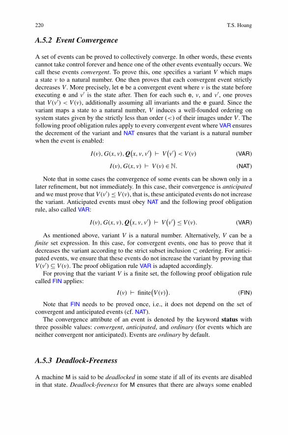
A set of events can be proved to collectively converge. In other words, these eventscannot take control forever and hence one of the other events eventually occurs. Wecall these events convergent. To prove this, one specifies a variant V which mapsa state v to a natural number. One then proves that each convergent event strictlydecreases V . More precisely, let e be a convergent event where v is the state beforeexecuting e and v′ is the state after. Then for each such e, v, and v′, one provesthat V(v′) < V(v), additionally assuming all invariants and the e guard. Since thevariant maps a state to a natural number, V induces a well-founded ordering onsystem states given by the strictly less than order (<) of their images under V . Thefollowing proof obligation rules apply to every convergent event where VAR ensuresthe decrement of the variant and NAT ensures that the variant is a natural numberwhen the event is enabled:
I(v),G(x, v),Q(
x, v, v′) � V(
v′) < V(v) (VAR)
I(v),G(x, v) � V(v) ∈ N. (NAT)
Note that in some cases the convergence of some events can be shown only in alater refinement, but not immediately. In this case, their convergence is anticipatedand we must prove that V(v′) ≤ V(v), that is, these anticipated events do not increasethe variant. Anticipated events must obey NAT and the following proof obligationrule, also called VAR:
I(v),G(x, v),Q(
x, v, v′) � V(
v′) ≤ V(v). (VAR)
As mentioned above, variant V is a natural number. Alternatively, V can be afinite set expression. In this case, for convergent events, one has to prove that itdecreases the variant according to the strict subset inclusion ⊂ ordering. For antici-pated events, we ensure that these events do not increase the variant by proving thatV(v′) ⊆ V(v). The proof obligation rule VAR is adapted accordingly.
For proving that the variant V is a finite set, the following proof obligation rulecalled FIN applies:
I(v) � finite(
V(v))
. (FIN)
Note that FIN needs to be proved once, i.e., it does not depend on the set ofconvergent and anticipated events (cf. NAT).
The convergence attribute of an event is denoted by the keyword status withthree possible values: convergent, anticipated, and ordinary (for events which areneither convergent nor anticipated). Events are ordinary by default.
A.5.3 Deadlock-Freeness
A machine M is said to be deadlocked in some state if all of its events are disabledin that state. Deadlock-freeness for M ensures that there are always some enabled

A An Introduction to the Event-B Modelling Method 221
events during the execution of M. Assume that M contains a set of n events ei (i ∈1, . . . , n) of the following form:
ei =̂ any xi where Gi (xi , v) then Qi (xi , v) . end
The proof obligation rule for deadlock-freeness3 is as follows:
I(v) � (∃x1 ·G1(x1, v)) ∨ · · · ∨ (∃xn ·Gn(xn, v)
)
. (DLF)
A.5.4 Example. Machine m0
We develop machine m0 of the initial model, focusing on courses opening and clos-ing. This machine sees context coursesCtx as developed in Sect. A.4.1, and as aresult has access to the carrier set CRS and constant m. We model the set of openedcourses by a variable, namely crs (REQ 5). Invariant inv0_1 states that it is a subsetof available courses CRS. A consequence of this invariant and of axiom axm0_1 isthat crs is finite, and this is stated in m0 as theorem thm0_2. Requirement REQ 8 isdirectly captured by invariant inv0_2: the number of opened courses, i.e., card(crs)is bounded above by m. Initially, all courses are closed; hence crs is set to the emptyset (∅).
variables: crs
invariants:inv0_1 : crs ⊆ CRSthm0_2 : finite(crs)inv0_2 : card(crs) ≤ m
initbegin
crs := ∅
end
We model the opening and closing of courses using two events OpenCourses andCloseCourses as follows (REQ 6 and REQ 7).
OpenCoursesstatus ordinarywhen
grd0_1 : card(crs) �= mthm0_3 : crs �= CRS
thenact0_1 : crs :| crs ⊂ crs′ ∧ card(crs′) ≤ m
end
CloseCoursesstatus anticipatedany cs where
grd0_1 : cs ⊆ crsgrd0_2 : cs �= ∅
thenact0_1 : crs := crs \ cs
end
We deliberately choose to model these events using different features of Event-B.In OpenCourses, we use a nondeterministic action to model the fact that some newcourses are opened, i.e. crs ⊂ crs′, as long as the number of opened courses will notexceed its limit, i.e. card(crs′) ≤ m. The guard of the event states that the currentnumber of opened courses has not yet reached the limit.
3Typically, this is encoded as a theorem in the machine after all invariants.

222 T.S. Hoang
CloseCourses models the set of courses that are going to be closed using pa-rameter cs. It is a non-empty set of currently opened courses which is captured byCloseCourses’ guard. The action is modelled in a straightforward way by removingcs from set crs.
We set the convergence status for OpenCourses and CloseCourses to be ordinaryand anticipated, respectively. We postpone the reasoning about the convergence ofCloseCourses till later refinements. Our intention is to prove that there can onlybe a finite number of occurrences of CloseCourses between any two OpenCoursesevents.
A.5.4.1 Proof Obligations
We present some of the obligations to illustrate what needs to be proved for the con-sistency of m0. We applied the proof obligation rules as shown earlier in this section.Notice that we can take the axioms and theorems of the seen context coursesCtx ashypotheses in the proof obligations. For clarity, we show only the parts of the hy-potheses that are relevant for discharging the proof obligations. Moreover, we alsoshow the proof obligations in their simplified forms, e.g. when event assignmentsare deterministic.
thm0_2/THM This obligation corresponds to the rule THM, in order to ensurethat thm0_2 is derivable from previously declared invariants.
. . .
finite(CRS)
crs ⊆ CRS�
finite(crs)
thm0_2/THM
The proof obligation holds trivially since crs is a subset of a finite set, i.e., CRS.
init/inv0_2/INV This obligation ensures that the initialisation init establishes in-variant inv0_2.
. . .
0 ≤ m�
card(∅) ≤ m
init/inv0_2/INV
Since the cardinality of the empty set ∅ is 0, the proof obligation holds trivially.
OpenCourses/thm0_3/THM This obligation ensures that thm0_3 is derivablefrom the invariants and the previously declared guards of OpenCourses.

A An Introduction to the Event-B Modelling Method 223
. . .
m ≤ card(CRS)
crs ∈ P(CRS)
card(crs) ≤ mcard(crs) �= m
�crs �= CRS
OpenCourses/thm0_3/THM
Informally, we can derive from the hypotheses that card(crs) < card(CRS); hencecrs must be different from CRS.
OpenCourses/act0_1/FIS This obligation corresponds to rule FIS and ensuresthat the nondeterministic assignment of OpenCourses is feasible when the event isenabled.
. . .
crs �= CRScard(crs) ≤ mcard(crs) �= m
�∃crs′ ·crs ⊂ crs′ ∧ card(crs′) ≤ m
OpenCourses/act0_1/FIS
The reasoning about the proof obligation is as follows. Since crs is differentfrom CRS, there exists an element c which is closed, i.e., not in crs. By adding c tothe set of opened courses, we strictly increase the number of opened courses by 1.Moreover, the number of opened courses after executing the event is still within thelimit since originally it is strictly below the limit.
CloseCourses/inv0_2/INV This obligation corresponds to rule INV and is sim-plified accordingly since the assignment is deterministic. The purpose of the obliga-tion is to prove that CloseCourses maintains invariant inv0_2.
. . .
card(crs) ≤ m�
card(crs \ cs) ≤ m
CloseCourses/inv0_2/INV
Since removing some courses cs from the set of opened courses crs can only reduceits number, the proof obligation can be trivially discharged.
DLF/THM The deadlock-freeness condition is encoded as theorem DLF of ma-chine m0, which results in the following proof obligation.
. . .
0 < m�
(card(crs) �= m) ∨ (∃cs·cs ⊆ crs ∧ cs �= ∅)
DLF/THM

224 T.S. Hoang
We reason as follows. If card(crs) �= m, the goal trivially holds. Otherwise, ifcard(crs) = m, since m �= 0, crs �= ∅. As a result, we can prove that ∃cs·cs ⊆crs ∧ cs �= ∅ by instantiating cs with crs.
A.6 Context Extension
Context extension is a mechanism for introducing more static details into an Event-Bdevelopment. A context can extend one or more contexts. When describing a contextD as extending another context C, we call C and D the abstract and concrete context,respectively. By extending C, D “inherits” all the abstract elements of C, i.e., carriersets, constants, axioms and theorems. This means that (1) a context extending Dalso implicitly extends C, and (2) a machine seeing D also implicitly sees C. As aresult, proof obligation rule THM for D also has additional assumptions in the formof axioms and theorems from the abstract context C.
Subsequently, we present three new contexts that we use in the next refinementof our running example.
A.6.1 Context membersCtx
This is an initial context (i.e., it does not extend any other context) containing acarrier set MEM. MEM represents the set of club members, with an axiom statingthat it is finite.
carrier sets: MEMaxioms:
axm1_1 : finite(MEM)
A.6.2 Context participantsCtx
This context extends the previously defined context membersCtx and is as follows.
constants: PRTCPT
axioms:axm1_2 : PRTCPT ⊆ MEMthm1_1 : finite(PRTCPT)
Constant PRTCPT denotes the set of participants that must be members of the clubas specified in ASM 2 (axm1_2). Theorem thm1_1 states that there can be only afinite number of participants, which gives rise to the following trivial proof obliga-tion.

A An Introduction to the Event-B Modelling Method 225
finite(MEM)
PRTCPT ⊆ MEM�
finite(PRTCPT)
thm1_1/THM
An important point is that axiom axm1_1 of the abstract context membersCtx ap-pears as a hypothesis in the proof obligation.
A.6.3 Context instructorsCtx
This context extends two contexts, coursesCtx and membersCtx, and introducestwo constants, namely INSTR and instrs. INSTR models the set of instructors thatare members of the club as specified by ASM 1 (axm1_3). Constant instrs modelsthe relationship between courses and instructors and is constrained by axm1_4: itis a total function from CRS to INSTR, and hence directly formalises requirementASM 4. Recall the definition of total function f from set S to set T : f is a relationfrom S to T where every element in S has exactly one mapping to some elementin T .
constants: INSTR, instrs
axioms:axm1_3 : INSTR ⊆ MEMaxm1_4 : instrs ∈ CRS → INSTR
The hierarchy of context extensions for our example is summarised in the fol-lowing diagram.
A.7 Machine Refinement
Machine refinement is a mechanism for introducing details about the dynamic prop-erties of a model [2]. For more details on the theory of refinement, we refer thereader to the Action System formalism [4], which has inspired the development ofEvent-B. We present here the proof obligations defined in Event-B, related to refine-ment. When speaking about machine N refining another machine M, we refer to Mas the abstract machine and to N as the concrete machine.
Despite the fact that the formal definition of Event-B refinement does not distin-guish between superposition refinement and data refinement, we illustrate them inseparate sections to show different aspects of the two. In superposition refinement,the abstract variables of M are retained in the concrete machine N, with possiblysome additional concrete variables. In data refinement, the abstract variables v are

226 T.S. Hoang
replaced by concrete variables w and, subsequently, the connections between M andN are represented by the relationship between v and w. In fact, more often, Event-B refinement is a mixture of both superposition and data refinement: some of theabstract variables are retained, while others are replaced by new concrete variables.
A.7.1 Superposition Refinement
As mentioned earlier, in superposition refinement, variables v of the abstract ma-chine M are kept in the refinement, i.e. as part of the state of N. Moreover, N canhave some additional variables w. The concrete invariants J(v,w) specify the rela-tionship between the old and new variables. Each abstract event e is refined by aconcrete event f (later on we will relax this one-to-one constraint). Assume that theabstract event e and the concrete event f are as follows:
e =̂ any x where G(x, v) then Q(x, v) end
f =̂ any x where H(x, v,w) then R(x, v,w) end
We assume now that e and f have the same parameters x. The more general case,where the parameters are different, is presented in Sect. A.7.2.
Somewhat simplifying, we say that f refines e if the guard of f is stronger than thatof e (guard strengthening), concrete invariants J are maintained by f, and abstractaction Q simulates the concrete action R (simulation). These conditions are statedas the following proof obligation rules:
I(v), J(v,w),H(x, v,w) � G(x, v) (GRD)
I(v), J(v,w),H(x, v,w),R(
x, v,w, v′,w′) � Q(
x, v, v′) (SIM)
I(v), J(v,w),H(x, v,w),R(
x, v,w, v′,w′) � J(
v′,w′) (INV)
In particular, if the guard and action of an abstract event are retained in the concreteevent, the proof obligations GRD and SIM are trivial; hence we only need to considerINV for proving that the gluing invariants are reestablished.
Proof obligations are generated to ensure that each assignment of concrete eventf is feasible. In the case where the action of the abstract event is retained in f, weonly need to prove the feasibility of any additional assignment.
In the course of refinement, new events are often introduced into a model. Newevents must be shown to refine the implicit abstract event SKIP, which does nothing,i.e., does not modify abstract variables v.
A.7.1.1 Machine m1
Machine m1 sees contexts instructorsCtx and participantsCtx. As a result, it implic-itly sees coursesCtx and membersCtx. Variable crs is retained in this refinement.

A An Introduction to the Event-B Modelling Method 227
An additional variable prtcpts representing information about course participants isintroduced. Invariant inv1_1 models prtcpts as a relation between the set of openedcourses crs and the set of participants PRTCPT . Requirement REQ 10 is directlymodelled by invariant inv1_2: for every opened course c, the instructor of thiscourse, i.e., instrs(c), is not amongst its participants, represented by prtcpts[{c}].
variables: crs,prtcpts
invariants:inv1_1 : prtcpts ∈ crs ↔ PRTCPTinv1_2 : ∀c · c ∈ crs ⇒ instrs(c) /∈ prtcpts[{c}]
initbegin
. . .
prtcpts := ∅
end
Initially, there are no opened courses; hence prtcpts is assigned to be ∅.The original abstract event OpenCourses stays unchanged in this refinement,
while an additional assignment is added to CloseCourses to update prtcpts by re-moving the information about the set of closing courses cs from it.
CloseCoursesstatus anticipatedany cs where
. . .
then. . .
act1_2 : prtcpts := cs �− prtcptsend
A new event is added, namely Register, to model the registration of a participantp for an opened course c. The guard of the event ensures that p is not the instructorof the course (grd1_3) and is not yet registered for the course (grd1_4). The actionof the event updates prtcpts accordingly by adding the mapping c �→ p to it.
Registerstatus convergentany p, c where
grd1_1 : p ∈ PRTCPTgrd1_2 : c ∈ crsgrd1_3 : p �= instrs(c)grd1_4 : c �→ p /∈ prtcpts
thenact1_1 : prtcpts := prtcpts ∪ {c �→ p}
end
We attempt to prove that Register is convergent and CloseCourses is anticipatedusing the following variant.

228 T.S. Hoang
variant: (crs × PRTCPT) \ prtcpts
The variant is a set of mappings; each links an opened course to a participantwho has not registered for the respective course.
We present some of the important proof obligations for m1. Proof obligationsGRD and SIM are trivial for events OpenCourses and CloseCourses. Consequently,we only need to consider INV for these old events.
CloseCourses/inv1_2/INV This obligation is to ensure that inv1_2 is main-tained by CloseCourses. The obligation is trivial, in particular, because, given thatc /∈ cs, (cs �− prtcpts)[{c}] is the same as prtcpts[{c}].
. . .
∀c · c ∈ crs ⇒ instrs(c) /∈ prtcpts[{c}]�
∀c · c ∈ crs \ cs ⇒ instrs(c) /∈ (cs �− prtcpts)[{c}]CloseCourses/inv1_2/INV
Register/inv1_1/INV This obligation is to guarantee that inv1_1 is maintainedby the new event Register.
. . .
prtcpts ∈ crs ↔ PRTCPTp ∈ PRTCPTc ∈ crs
�prtcpts ∪ {c �→ p} ∈ crs ↔ PRTCPT
Register/inv1_1/INV
FIN This obligation is to ensure that the declared variant used for proving conver-gence of events is finite (FIN). This is trivial, since the set of opened courses crs andthe set of participants PRTCPT are both finite.
. . .
finite(crs)finite(PRTCPT)
�finite((crs × PRTCPT) \ prtcpts)
FIN
CloseCourses/VAR This proof obligation corresponds to rule VAR, ensuring thatanticipated event CloseCourses does not increase the variant.
. . .
�((crs \ cs) × PRTCPT) \ (cs �− prtcpts)
⊆(crs × PRTCPT) \ prtcpts)
CloseCourses/VAR

A An Introduction to the Event-B Modelling Method 229
Register/VAR This proof obligation corresponds to rule VAR, ensuring that theconvergent event Register decreases the variant. This is trivial since a new mappingc �→ p is added to prtcpts, effectively increasing it, and hence strictly decreasing thevariant.
. . .
c �→ p /∈ prtcpts�
(crs × PRTCPT) \ (prtcpts ∪ {c �→ p}))⊂
(crs × PRTCPT) \ prtcpts)
Register/VAR
A.7.2 Data Refinement
In data refinement, abstract variables v are removed and replaced by concrete vari-ables w. The states of abstract machine M are related to the states of concrete ma-chine N by gluing invariants J(v,w). In Event-B, the gluing invariants J are declaredas invariants of N and also contain the local concrete invariants, i.e., those constrain-ing only concrete variables w.
Again, we assume a one-to-one correspondence between an abstract event e anda concrete event f. Let e and f be as follows:4
e =̂ any x where G(x, v) then Q(x, v) end
f =̂ any y where H(y,w) then R(y,w) end
As with superposition refinement, we can say that f refines e if the guard of f isstronger than the guard of e (guard strengthening), and the gluing invariants J(v,w)
establish a simulation of f by e (simulation). This condition is captured by the fol-lowing proof obligation rule:
I(v)J(v,w)
H(y,w)
R(
y,w,w′)
�∃x, v′ ·G(x, v) ∧ Q
(
x, v, v′) ∧ J(
v′,w′)
(A.7)
In order to simplify and split the above proof obligation, Event-B introduces thenotion of “witnesses” for the abstract parameters x and the after value of the ab-stract variables v′. Witnesses are predicates of the form W1(x, y, v,w,w′) (for x)
4Concrete events may be annotated with abstract events name and witnesses, which we will showlater.

230 T.S. Hoang
and W2(v′, y, v,w,w′) (for v′), which are required to be feasible. The correspondingproof obligations are as follows:
I(v), J(v,w),H(y,w),R(
y,w,w′) � ∃x·W1(
x, y, v,w,w′) (WFIS)
I(v), J(v,w),H(y,w),R(
y,w,w′) � ∃v′ ·W2(
v′, y, v,w,w′) (WFIS)
Typically, witnesses are declared deterministically, i.e. in the form x = · · · or v′ =· · · . In these cases, witnesses are trivially feasible; hence the corresponding proofobligations are omitted.
Given the witnesses, the refinement proof obligation (A.7) is replaced by threedifferent proof obligations as follows:
I(v), J(v,w),H(y,w),W1(
x, y, v,w,w′) � G(x, v) (GRD)
I(v), J(v,w),H(y,w),R(
y,w,w′),W1(
x, y, v,w,w′),W2(
v′, y, v,w,w′) � Q(
x, v, v′)
(SIM)
I(v), J(v,w),H(y,w),R(
y,w,w′),W1(
x, y, v,w,w′),W2(
v′, y, v,w,w′) � J(
v′,w′)
(INV)
The concrete event f can be denoted by the abstract event e (using keyword refines)and the witnesses (using keyword with) as follows:
frefines eany y where
H(y,w)
withx : W1(x, y, v,w,w′)v′ : W2(v′, y, v,w,w′)
thenR(y,w)
end
The action of the concrete event is required to be feasible. The correspondingproof obligation FIS is similar to the one presented for the abstract machine, withthe exception that both abstract and gluing invariants can be assumed.
For newly introduced events, as with superposition refinement, they must beproved to refine the implicit abstract event SKIP, which is unguarded and does noth-ing, i.e. does not modify abstract variables v. In this case, GRD is trivial, since theabstract guard is �. For SIM and INV, we omit references to W1 (since there are noparameters for the abstract SKIP event). Moreover, the witness W2 for v′ is trivial:v′ = v.
As mentioned earlier, in general, Event-B refinement is a mixture of both super-position and data refinement. Often, some (not all) abstract variables are retained

A An Introduction to the Event-B Modelling Method 231
in the refinement, while the other abstract variables are replaced by new concretevariables. Similarly, some abstract parameters can be present in the concrete event,where other parameters are replaced by some new concrete ones. In general, weonly need to give witnesses to disappearing variables and parameters.
The one-to-one correspondence between the abstract and concrete events can berelaxed. When an abstract event e is refined by more than one concrete event f, wesay that the abstract event e is split and prove that each concrete f is a valid refine-ment of the abstract event. Conversely, several abstract events e can be refined byone concrete f. We say that these abstract events are merged together. A requirementfor merging events is that the abstract events must have identical actions. Whenmerging events, we need to prove that the guard of the concrete event is strongerthan the disjunction of the guards of the abstract events.
The concrete machine N can be proved to be relatively deadlock-free with re-spect to the abstract machine M. It means that if M can continue in some state, socan N. Assume that M contains a set of n events ei (i ∈ 1, . . . , n) of the followingform:
ei =̂ any xi where Gi (xi , v) then Qi (xi , v) end
Assume that N contains a set of m events fj (j ∈ 1, . . . ,m) of the followingform:
fj =̂ any yi where Hi (yi ,w) then Ri (yi ,w) end
The proof obligation rule for relative deadlock-freeness5 is as follows:
I(v)J(v,w)(∃x1 ·G1(x1, v)
) ∨ · · · ∨ (∃xn ·Gn(xn, v))
�(∃y1 ·H1(y1,w)
) ∨ · · · ∨ (∃ym ·Hm(ym,w))
(REL_DLF)
A.7.2.1 Machine m2
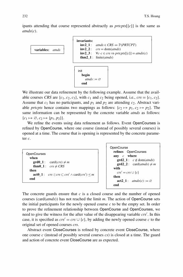
We perform a data refinement by replacing abstract variables crs and prtcpts bya new concrete variable atnds. This machine does not explicitly model any re-quirements from Sect. A.3: it implicitly inherits requirements from previous ab-stract machines. As stated in invariant inv2_1, atnds is a partial function fromCRS to some set of participants (i.e., member of P(PRTCPT)). Invariants inv2_2and inv2_3 act as gluing invariants, linking abstract variables crs and prtcptswith concrete variable atnds. Invariant inv2_2 specifies that crs is the domainatnds. Invariant inv2_3 states that for every opened course c, the set of partic-
5Typically, this is encoded as a theorem in N after declaration of all invariants.
232 T.S. Hoang
ipants attending that course represented abstractly as prtcpts[{c}] is the same asatnds(c).
variables: atnds
invariants:inv2_1 : atnds ∈ CRS �→ P(PRTCPT)
inv2_2 : crs = dom(atnds)inv2_3 : ∀c·c ∈ crs ⇒ prtcpts[{c}] = atnds(c)thm2_1 : finite(atnds)
initbegin
atnds := ∅
end
We illustrate our data refinement by the following example. Assume that the avail-able courses CRS are {c1, c2, c3}, with c1 and c2 being opened, i.e., crs = {c1, c2}.Assume that c1 has no participants, and p1 and p2 are attending c2. Abstract vari-able prtcpts hence contains two mappings as follows: {c2 �→ p1, c2 �→ p2}. Thesame information can be represented by the concrete variable atnds as follows:{c1 �→∅, c2 �→ {p1,p2}}.
We refine the events using data refinement as follows. Event OpenCourses isrefined by OpenCourse, where one course (instead of possibly several courses) isopened at a time. The course that is opening is represented by the concrete parame-ter c.
OpenCourseswhen
grd0_1 : card(crs) �= mthm0_1 : crs �= CRS
thenact0_1 : crs :| crs ⊂ crs′ ∧ card(crs′) ≤ m
end
OpenCourserefines OpenCoursesany c where
grd2_1 : c /∈ dom(atnds)grd2_2 : card(atnds) �= m
withcrs′ = crs ∪ {c}
thenact2_1 : atnds(c) := ∅
end
The concrete guards ensure that c is a closed course and the number of openedcourses (card(atnds)) has not reached the limit m. The action of OpenCourse setsthe initial participants for the newly opened course c to be the empty set. In orderto prove the refinement relationship between OpenCourse and OpenCourses, weneed to give the witness for the after value of the disappearing variable crs′. In thiscase, it is specified as crs′ = crs ∪ {c}, by adding the newly opened course c to theoriginal set of opened courses crs.
Abstract event CloseCourses is refined by concrete event CloseCourse, whereone course c (instead of possibly several courses cs) is closed at a time. The guardand action of concrete event CloseCourse are as expected.

A An Introduction to the Event-B Modelling Method 233
CloseCoursesstatus anticipatedany cs where
grd0_1 : cs ⊆ crsgrd0_2 : cs �= ∅
thenact0_1 : crs := crs \ csact2 : prtcpts := cs �− prtcpts
end
CloseCourserefines CloseCoursesstatus convergentany c where
grd2_1 : c ∈ dom(atnds)with
cs = {c}then
act2_1 : atnds := {c}�− atndsend
We need to give the witness for the disappearing abstract parameter cs. It is specifiedstraightforwardly as cs = {c}. Notice also that we change the convergence status ofCloseCourse from anticipated to convergent. We use the following variant to provethat CloseCourse is convergent.
variant: card(atnds)
The variant represents the number of mappings in atnds, and since it is a par-tial function, it is also the same as the number of elements in its domain, i.e.card(atnds) = card(dom(atnds)). As a result, the variant represents the number ofopened courses.
Event Register is refined as follows:6 references to crs and prtcpts in guard andaction are replaced by references to atnds.
(abs_)Registerany p, c where
grd1_1 : p ∈ PRTCPTgrd1_2 : c ∈ crsgrd1_3 : p �= instrs(c)grd1_4 : c �→ p /∈ prtcpts
thenact1_1 : prtcpts := prtcpts ∪ {c �→ p}
end
(cnc_)Registerrefines Registerany p, c where
grd2_1 : p ∈ PRTCPTgrd2_2 : c ∈ dom(attendees)
grd2_3 : p �= instrs(c)grd2_4 : p /∈ atnds(c)
thenact2_1 : atnds(c) := atnds(c) ∪ {p}
end
We now show some proof obligations for proving the refinement of m1 by m2.
OpenCourse/act0_1/SIM This proof obligation corresponds to rule SIM, ensur-ing that the action act0_1 of abstract event OpenCourses can simulate the action ofconcrete event OpenCourse. Notice the use of the witness for crs′ as a hypothesisin the obligation.
6We use prefixes (abs_) and (cnc_) to denote the abstract and concrete versions of the event,respectively.

234 T.S. Hoang
. . .
atnds ∈ CRS �→ P(PRTCPT)
crs = dom(attendees)c /∈ dom(attendees)card(attendees) �= mcrs′ = crs ∪ {c}
�crs ⊂ crs′ ∧ card(crs′) ≤ m
OpenCourse/act0_1/SIM
CloseCourse/grd0_1/GRD This proof obligation corresponds to rule GRD, en-suring that the guard of concrete event CloseCourse is stronger than the abstractguard grd0_1 of abstract event CloseCourses. Note the use of the witness for cs asa hypothesis in the obligation.
. . .
crs = dom(atnds)c ∈ dom(atnds)cs = {c}
�cs ⊆ crs
CloseCourse/grd0_1/GRD
CloseCourse/NAT This proof obligation corresponds to rule NAT on page 220;it ensures that the variant is a natural number when CloseCourse is enabled.
. . .
finite(atnds)�
card(atnds) ∈ N
CloseCourse/NAT
CloseCourse/VAR This proof obligation corresponds to rule VAR on page 220;it ensures that the variant is strictly decreased by CloseCourse. The obligation istrivial since the variant represents the number of opened courses and CloseCoursecloses one of them.
. . .
atnds ∈ CRS �→ PRTCPTc ∈ dom(atnds)
�card({c}�− atnds) < card(atnds)
CloseCourse/VAR
A.8 Summary of the Development
The summary of the hierarchy of the development is illustrated in Fig. A.1.Table A.3 summarises how assumptions and requirements are taken into account
in our formal development. Note that the last refinement, m2, does not explicitly

A An Introduction to the Event-B Modelling Method 235
Fig. A.1 Development hierarchy
Table A.3 RequirementsTracing Requirement Models Requirement Models
ASM 1 instructorsCtx REQ 6 m0
ASM 2 participantsCtx REQ 7 m0
ASM 3 coursesCtx REQ 8 m0
ASM 4 instructorsCtx REQ 9 m1
REQ 5 m0 REQ 10 m1
take into account any requirements. Indeed, the requirements are implicitly inheritedfrom the abstract machines through the refinement relationship.
The development is formalised and proved using the supporting Rodin platform7
for Event-B [3] and is available online.8 The summary of the proof statistics for the
Table A.4 Proof statistics
Constructs Proof obligations Automatic (%) Manual (%)
coursesCtx 2 2 (100 %) 0 (0 %)
membersCtx 0 0 (N/A) 0 (N/A)
instructorsCtx 0 0 (N/A) 0 (N/A)
participantsCtx 1 1 (100 %) 0 (0 %)
m0 11 8 (73 %) 3 (27 %)
m1 14 13 (93 %) 1 (7 %)
m2 29 26 (90 %) 3 (10 %)
Total 57 50 (88 %) 7 (12 %)
7At the time of writing, we use Rodin version 2.4.0.8http://deploy-eprints.ecs.soton.ac.uk/371/.

236 T.S. Hoang
development is shown in Table A.4. Around 50 % of the proof obligations appearin m2, where we perform data refinement. Typically, data refinement involves radi-cal changes to developments, since when replacing abstract variables with concretevariables, it is also necessary to adapt the events accordingly.
References
1. Abrial, J.-R.: The B-Book: Assigning Programs to Meanings. Cambridge University Press,Cambridge (1996)
2. Abrial, J.-R.: Modeling in Event-B: System and Software Engineering. Cambridge UniversityPress, Cambridge (2010)
3. Abrial, J.-R., Butler, M., Hallerstede, S., Hoang, T.S., Mehta, F., Voisin, L.: Rodin: An opentoolset for modelling and reasoning in Event-B. Int. J. Softw. Tools Technol. Transf. 12(6),447–466 (2010)
4. Back, R.-J.: Refinement calculus II: Parallel and reactive programs. In: de Bakker, J.W.,de Roever, W.P., Rozenberg, G. (eds.) Stepwise Refinement of Distributed Systems, Mook, TheNetherlands, May 1989. Lecture Notes in Computer Science, vol. 430, pp. 67–93. Springer,Berlin (1990)
5. Chandy, K., Misra, J.: Parallel Program Design: A Foundation. Addison-Wesley, Reading(1989)
6. Lamport, L.: The temporal logic of actions. Trans. Program. Lang. Syst. 6(3), 872–923 (1994)7. Mehta, F.: Proofs for the working engineer. PhD thesis, ETH Zurich (2008)8. Schmalz, M.: The logic of Event-B. Technical Report 698, Institute of Information Security,
ETH Zurich (October 2010). http://www.inf.ethz.ch/research/disstechreps/techreports/show?serial=698

Appendix BEvidence-Based Assistance for the Adoptionof Formal Methods in Industry
Jean-Christophe Deprez, Christophe Ponsard, and Renaud De Landtsheer
Abstract Managing change in industrial development processes is often a chal-lenge. It involves many levels of the organisation: top management, who need tounderstand the benefits and impacts of change, project managers, who need to un-derstand new processes and adapt their planning and monitoring practices, and engi-neers, who need to be trained in the use of new methods and tools. This is especiallytrue for the introduction of Formal Methods (FM), which may significantly impactsoftware development lifecycle processes. Industries that seek to adopt formal meth-ods often need assistance in understanding their benefits, what formal methods canbe used at what phase of the development lifecycle and what strategy should beused for a successful deployment of formal methods. During the DEPLOY project,an entire segment of work was dedicated to collecting important material to use asevidence, to provide answers to recurring concerns of companies wishing to inves-tigate the use of formal methods. This appendix presents the overall approach usedto collect and structure DEPLOY material as an evidence repository, notably, usingsuccess stories and Frequently Asked Questions (FAQs). These are fully publishedon www.fm4industry.org. A sample of success stories and FAQs answers are given,along with explanations on how companies in typical industry situations can navi-gate the evidence repository to find information relevant to their contexts. Finally,we also discuss how an industry engaged in an adoption process can set up its owninternal evidence based on its specific context and how it can share its experiencewithout compromising potentially confidential information.
J.-C. Deprez (B) · C. Ponsard · R. De LandtsheerCETIC, Rue des Frères Wright 29/3, Charleroi, Belgiume-mail: [email protected]
C. Ponsarde-mail: [email protected]
R. De Landtsheere-mail: [email protected]
A. Romanovsky, M. Thomas (eds.), Industrial Deployment of System EngineeringMethods, DOI 10.1007/978-3-642-33170-1,© Springer-Verlag Berlin Heidelberg 2013
237

238 J.-C. Deprez et al.
B.1 Introduction
Industry projects heavily rely on quantitative data when assessing project progressor product quality. However, in the early stage of transferring research results toindustry, qualitative information can add very important value. A method based onmeasurement was proposed during the first year of the DEPLOY project, but it wasrejected by Industry partners. Their main reasons for refusing an assessment basedon measurements were confidentiality and a belief that numbers would not providethe right type of information to present a convincing argument for promoting formalmethods within their organisation. In particular, DEPLOY industry partners recog-nised that quantitative methods are more appropriate for streamlined developmentprojects, where a development approach is mastered by all project participants. Onthe other hand, in research transfer, where industry participants must understandnew concepts, qualitative information is much more appropriate and convincing.DEPLOY industry partners also stressed the need to present evidence material in aform convenient for industry, such as well-structured Frequently Asked Questions(FAQs).
General surveys, such as that reported in [10] and a later extended one includedin this book, confirm the need to provide evidence to support the adoption pro-cess by companies considering the use of Formal Methods (FM). The goal of thisappendix is to describe an approach to presenting and exploiting informationrelated to FM adoption by industry. The starting point was the concept of evi-dence. However, this needed to be further analysed in order to define how evidencecould best provide information about formal methods to industry and in particular,about formal methods explored during the DEPLOY project. While one of the pur-poses for collecting evidence was to help industry partners of the DEPLOY projectin their adoption process, the main target audience is organisations not involved inDEPLOY.
The sections of this appendix are organised as follows. First, a discussion elab-orates on what constitutes evidence of formal method use in industry. From this, ageneral method for collecting and presenting evidence material is proposed. Sec-ond, different approaches are presented to searching for evidence material useful inone’s context; in particular, different scenarios covering various industry sectors anddifferent staff roles are presented. Then, some concrete exploitation scenarios of thematerial available online are highlighted. Finally, methods and tools for evidencecollection and presentation within an organisation are proposed, including ways tobe used by the organisation to share its experience with others.
B.2 A Method for Collecting and Presenting Evidence
Success stories have been shown to be an efficient way of collecting evidence ofsuccessful industry adoption. They often take the form of white papers. In somecases, they are published in industry tracks of conferences. Such publications rarely

B Evidence-Based Assistance for the Adoption of Formal Methods in Industry 239
Table B.1 A specific “success story” template
Name Short meaningful identification to use as the title of the story.
Keywords List of keywords helping in the classification of the success story.
Short description Description (in a few lines) of what the story is about and what claims aresupported.
Source Organisation that contributed to the work of this story and a contextual de-scription of the company’s structure and research and innovation process.
Benefits Positive impacts that can be inferred from the success story. (Note:Themes/questions from the FAQs highlight the important points on whichimpact are sought; hence one should review them when listing the benefitshighlighted in the success story.)
Limitations Limitations identified (not definitive if the story is ongoing): these are poten-tial show stoppers and barriers to overcome.
Elaboration Complete description of the work done to document the success story.
Consolidation Additional arguments reported in the scientific literature corroborating thesuccess story, including citations of scientific publications presenting thesearguments.
Further work Specific work still to be done by DEPLOY partners to make the story asuccess.
References List of publications or reports related to the success story.
Related FAQs List of questions in the FAQs to which this success story provided material.
allow sufficient space. Consequently, success stories often lack details of the veryspecific contexts in which they took place; for example, little information is usuallyprovided about the overall innovation cycle of the enterprise involved in the suc-cess story, or on how researchers and production engineers collaborated during thetransfer project.
In conclusion, traditional success stories are an interesting base for building anevidence repository of industry adoption, but they must be augmented to providereaders with additional contextual information as well as links to related efforts.Consequently, a specific “success story” template was designed to enhance and sys-tematise the presentation of success stories emerging from the DEPLOY project.This template is presented in Table B.1.
The template above contains information on the context. In particular, the Sourcesection suggests that an organisation should describe its structure and its researchand innovation process. There can be large amounts of this context information.Hence it is recommended that the Source field should only provide the organisa-tion’s name and a link to another document that describes the full company context.This approach also has the added benefit that an enterprise with several successstories may often be linked to the same context document.
Success stories provide evidence of formal method transfer and usage in indus-try from a very specific viewpoint. By their very specific nature, success stories

240 J.-C. Deprez et al.
Fig. B.1 Organisation of theEvidence repository
do not, however, address high-level cross-concerns of various industry sectors or,at least, they do not present information in such a way that cross concerns canbe easily deduced. This means that success stories should be complemented byanother technique for presenting topics of general concern to many readers fromvarious industries. During the DEPLOY project, researchers and industry partnersproposed structuring this cross-cutting information in the Frequently Asked Ques-tions (FAQs) format. Industry partners are accustomed to this type of format, wheregeneric questions are answered in a fairly limited space. During DEPLOY, the aver-age length targeted for answers was about one page as illustrated in the next section.The resulting structure of our evidence repository is shown in Fig. B.1.
At this point, it is necessary to identify a fairly exhaustive list of common con-cerns from different industry sectors. For this purpose, many documents providedby the DEPLOY industry partners as well as by the academic researchers and thetool providers were analysed. The high-level topics identified are:
• The impact on an organisation with regards to training scope and resourcing• The impact on the software/system development process
– The impact on the quality of product (and its work product) developed usingformal methods,
– The capability to exploit formal models at various stages of the developmentprocess,
– The capability to perform reuse across development projects when formalmethods are used, including reuse of formal and proven artefacts,
– The capability to phase the learning of a formal method in an organisationand eventually limit the number of those who are expected to understand andbecome an expert in a formal method,
– The capability to phase the migration to the formal method use incrementally(given the existence of products initially developed without using formal meth-ods)
• Known strengths and weaknesses of tools associated with a formal method aswell as the quality of support by tool providers
• External factors advocating take-up (from competition, standards bodies, laws)of formal methods
• General concerns related to formal methods in industry

B Evidence-Based Assistance for the Adoption of Formal Methods in Industry 241
These various themes validated by the DEPLOY industry and academic partnersprovide the initial categories for which the FAQs needs to be formulated.
Pieces of evidence are labelled Industry Roles to specifically target the relevanttypes of audience and increase the impact of answers. The organisations involvedin DEPLOY were quite different, ranging from the technological SME with highlypolyvalent roles to large companies with a specific R&D unit and very well-definedroles. Based on a careful study of the innovation cycle of the involved companiesand on our experience in technology transfer, it was, however, possible to identifya set of key roles common to the DEPLOY partners, namely, high-level managers,project managers, engineers and technical analysts, and quality assurance staff. Fora transfer project to be successful, many of these people must be involved in andsupportive of the proposed transfer of research results. Thus, to obtain clear andconcise answers, each FAQ should always explicitly target a single role. This doesnot necessarily mean that other roles will not be interested in the question, but ratherthat the named role is the primary target; hence the answer is provided to match thisprimary role. For instance, the wording of an answer targeted at engineers is differ-ent from that targeted at high-level management. Thus, if a high-level manager isinterested in reading a FAQ answer primarily targeting engineers, he will understandthat the answer is presented from the engineer’s viewpoint. Making the targeted au-dience explicit by stating its roles definitely helps the reader.
In the context of transferring formal method engineering techniques to industry,the following roles were identified:
• High-Level Managers, who make strategic decisions and consider their financialimpact
• Project and QA Managers, who supervise active users of FM (in production orR&D), plan projects and perform safety analysis and more traditional QA activi-ties
• Engineers and Analysts, who actively use FM• QA Practitioners, who must understand documents involving FM notation but do
not need to develop the capabilities to produce them.
The FAQs approach suggests identifying questions of interest to each role foreach theme. The important subtlety is that a question in the FAQs must be:
• Generic enough to interest enough readers and not be the sole concern of a singlesector or, even worse, a single company.
• Specific enough so it is fairly easy to understand what results from an industrypilot should be proposed to what questions from the FAQs.
At the presentation level, the most adequate and commonly used medium is anInternet wiki, which gives wide access to the material. Wiki technology enablesfeedback from the people accessing the material, from comments to more activecontributions, with a degree of control or moderation that can be adjusted. There aremany Open Source wiki implementations, and we finally opted for Mediawiki [8],which is made very powerful by numerous extension plug-ins. Figure B.2 shows thehomepage, accessible at http://www.fm4industry.org.

242 J.-C. Deprez et al.
Fig. B.2 Organisation of the Evidence repository
B.3 Selected Highlights of FAQs and Success Stories
In this section we present selected FAQs and success stories to give some concreteand well-selected examples that will help the reader with the industrial background,interested in FM, to figure out what kind of information s/he can find and how it canhelp him/her. Those examples will serve to illustrate exploitation and productionscenarios presented in the next sections, so the appendix is self-contained.
B.3.1 FAQ I: What Is the Position of Standards Regarding FormalMethods in My Industry Segment?
Theme: External Factor Pushing for Formal Method Adoption (ExFac)Role: High-level Manager
B.3.1.1 Overview of Reference Standards for Safety-Critical Systems
The landscape of standards includes both generic and domain-specific standards.Figure B.3 shows a sectorial classification. A number of sectors have derived theirstandards from the generic IEC61508 standard while others have their own stand-alone standard.
• IEC 61511:2003 addresses industrial processes• IEC 61513:2001 addresses the nuclear industry

B Evidence-Based Assistance for the Adoption of Formal Methods in Industry 243
Fig. B.3 Sectorial classification of safety standards
• CE 62061:2005 addresses machine safety• CENELEC/EN 50126/50128/50129 targets the railway sector• ISO 26262:2011 addresses the automotive sector• IEC 62304:2006 addresses the medical sector• DO-178 addresses the aeronautic sector• ECSS addresses the space sector (ESA)
In the aeronautic and space sectors, there are standards not directly linked toIEC61508.
• DO-178 (1992) is for the aeronautic sector• ECSS is for the space sector
Figure B.3 shows a wide variety of standards. In addition to sector-specific con-straints, there are also a number of other reasons for such a variety of standards, in-cluding historical (uncoordinated work, national level) and market reasons (marketprotection) [3]. Moreover, standards evolve, hopefully towards better integration, sothey are revised (the publication year is often appended to their numerical identifier,as in EN 61508:2002) or made more specialised (as denoted by “B” in DO-178B).
Beyond this variety, standards exhibit common aspects:
• definition of safety assurance levels: all standards are based on a risk-orientedapproach to their safety functions, classifying them into a number of dependabil-ity classes, typically by specifying PFD (Probability of Failure on Demand) andRRF (Risk Reduction Factor) figures. This classification varies across standards;for example, in IEC 61508, the classification ranges from SIL1, which is the leastdependable, to SIL4, which is the most dependable. The DO-178B has a letter-based classification ranging from level “E”, the least dependable, to level “A”,which is the most dependable.
• prescription level: standards can be prescriptive (with an obligation to demon-strate compliance) or just give recommendations. However, in practice, deviatingfrom recommendations can be difficult as this may require non-trivial work tojustify it and to convince a certification body that is used to the well-established

244 J.-C. Deprez et al.
recommended practices. In this way, the introduction of formal methods de-pends on whether they are simply mentioned, recommended or highly recom-mended.
• scope: this can address the software, the hardware or the complex system as awhole. It can also focus on specific parts of the development process (such as thedevelopment lifecycle, quality management, safety assessment, or system certifi-cation).
B.3.1.2 Standards and Formal Methods: An Overview
Generic IEC61508 Based on the SILs defined earlier, IEC 61508 classifiesmethodologies, techniques and activities as “not recommended”, “recommended”,“highly recommended” and so on. Among the “highly recommended” techniquesfor SIL4 are inspection and reviewing, using an independent test team and use offormal methods.
A single “highly recommended” technique is not enough to ensure the requiredsafety, reliability and correctness: the standard requires a carefully chosen combi-nation of appropriate techniques. Achieving this in a project requires a dedicatedsystem engineering process as described in [6] to be defined.
Railway Sector The EN 50128 guidelines, issued by the European Commit-tee for Electrotechnical Standardisation (CENELEC), address the development of“Software for Railway Control and Protection Systems”, and constitute the mainreference for railway signalling equipment manufacturers in Europe, with their usespreading to other continents and other sectors of the railway industry (as well asother safety-related industries).
In EN 50128, Formal Methods/Proofs are explicitly identified as relevant tech-niques/measures for software requirements specification, software architecture,software design, implementation, verification and testing and data preparation tech-niques. More precisely, they are “recommended” for SILs 1 and 2 and “Highly Rec-ommended” for SILs 3 and 4. In particular, the Formal Methods cited include CCS,CSP, HOL, LOTOS, OBJ, Temporal Logic, VDM, Z and B. In the ongoing 2011revision of the standard, additional constraints are put on tools, especially code/datageneration tools, with respect to the need for a specification and for evidence thatthe implementations comply with it.
Despite this, and success stories such as that of the automated metro line 14 inParis (METEOR) [2], formal methods have not spread across the entire railway sig-nalling industry, where much software is still written and tested in traditional ways(with the testing effort usually adding up to more than 50 % of the developmenteffort). This lack of adoption is due to the investments needed to build up a for-mal methods culture, and to the high costs of commercial support tools. Moreover,equipment can be made to conform to CENELEC without applying formal meth-ods [1].

B Evidence-Based Assistance for the Adoption of Formal Methods in Industry 245
However, EN 50128 requires that the bug detection and bug fixing activities in-clude reviews of early phases. This costs more in terms of time and money. Con-sequently, companies are becoming interested in applying formal methods at thespecification and design phases as it is the only solution that transfers the effort tothe design team.
Another barrier is that, although mentioned in the standard, the certification bod-ies might not be familiar with Formal Methods, as most of the systems they certifyfollow a test-based approach. The first time a certification body is asked to certifya system whose justification relies on such a formal argument, they might requireadditional information to be convinced. Typically, there needs to be an indication ofthe level of expertise that an auditor should possess in order to perform certificationfor a company which bases its development on formal methods. Once certificationis acquired, each new system can easily follow the same path. Siemens has gonethrough this process with the B-method, and it is now accepted by the certificationbodies, so that subsequent projects have become easier to certify. In the specificmarket of metro lines, the B-method has even become the standard required by themarket.
Aeronautic Sector DO-178B was published a while ago, in 1992. It does notrecommend or propose a specific development process or methodology. The certifi-cation approach is to demonstrate compliance of the process and produced artefactswith a set of goals related to a number of lifecycle-related processes (planning, de-velopment, V&V, configuration and so on). As mentioned above, DO-178B ranksthe software category by five dependability classes: from A (most dependable: catas-trophic effect) to E (least dependable: no effect). The scope of the application offormal methods is the verification of software artefacts. In DO-178B, verificationcan also be achieved though a combination of review, analysis and testing activities.
With regard to Formal Methods, DO-178B categorises them as “alternative meth-ods” because, at the time the document was produced (1992), they were assessed asinadequately mature. However, they can be used “as long as they can be demon-strated to address the goals of the standard, and their usage is adequately plannedand described” [9].
A new revision DO-178C was published in January 2012. It is explicitly address-ing formal methods to complement dynamic testing; they can be used selectively oras the primary source of evidence.
Automotive Sector The sector-specific standard is ISO 26262 (derived from IEC61508). It recommends formal methods, but semi-formal methods are highly rec-ommended. In such ISO standards, many development methods can be “recom-mended”, but only one can be “highly recommended” (above all others). At thebeginning of the debate on ISO 26262, it was suggested that formal methods shouldbe highly recommended. After intensive lobbying from large automotive compa-nies, which are convinced that formal methods will incur a significant cost overhead,semi-formal methods have been given the “highly recommended” status, while for-mal methods are just recommended.

246 J.-C. Deprez et al.
B.3.1.3 Conclusion: Standards, Formal Methods and Possible Strategies
Some standards recommend or even highly recommend formal methods, but veryfew standards describe how to manage formal development. It is therefore difficultto prove that the development process complies with the standards. Certificationauthorities need to be convinced about this issue.
As formal methods are less widespread and certification authorities are less fa-miliar with them than with the classical development methods, there is more workto be done than with other methods, especially the first time, even though formalmethods can provide better arguments. However, the investment can be worth theeffort, as shown by the Siemens case for B.
B.3.2 FAQ II: Are the Tools Associated with a ParticularFormalism Backed by Responsive, Robust and EnduringOrganisations?
Theme: Known Strengths and Weaknesses of Tools and Tool Providers (TOOL)Role: High-Level Manager
B.3.2.1 Is There Guarantee of Long-Term Tool Availability and Support?
Industry projects may last tens of years from the development to the decommis-sioning of a system. It is therefore crucial for industry to ensure proper supportthroughout the complete project lifetime, including its retirement. Tools can be dis-tributed under Open Source or Proprietary Licences. Each model comes with itsown risk of disappearance (bankruptcy for proprietary code, community dissolu-tion for Open Source). Given the niche market, securing the support is a nontrivialtask (e.g., escrow for proprietary code, direct community involvement or support forOpen Source).
B.3.2.2 Is the Tool Reliable?
Closed source reliability is a matter of trust that can be provided by a certificationscheme for example. Concerns have been raised about whether Open Source toolscan achieve higher reliability [4]. However, the large number of industrial-strengthopen source tools available nowadays, e.g. PVS and NuSMV suggests that they can.One reason for this is that they will potentially be peer-reviewed by many; anotheris that distributed development requires better defined and carefully designed inter-faces at the design level. Furthermore, extensive test suites are often available forOpen Source tools.

B Evidence-Based Assistance for the Adoption of Formal Methods in Industry 247
B.3.2.3 Is the Tool Scalable?
The ability to scale up depends on different factors. Tool-induced limitations maybe due to the underlying formal technology, implementation problems (e.g., somebottleneck in a processing chain) or simply usability (e.g., limitations in managinglarge pieces of models). To assess scalability, references, feedback and reviews pro-vide initial information that is useful for completely ruling out tools inadequate forindustry. A second step is to challenge the tool on realistic case studies in variousindustry sectors, as the way models are built can also impact the ability to scale up.Open Source tools may be more likely to be unable to scale up, especially if they arestill at the R&D stage. However, there are also highly scalable Open Source tools inthe FM area (e.g., SPIN and NuSMV model-checkers, ACL2 and Isabelle theoremprovers).
B.3.2.4 Is the Tool Usable?
It is important that tools facilitate various tasks when building or modifying a model,carrying out validation and verification activities, supporting teamwork, and so on.Commercial tools generally have better usability because special attention is de-voted to this aspect, whereas Open Source tools tend to focus more on core func-tionality and efficiency, sometimes with only a command line interface.
B.3.2.5 Does the Tool Integrate Well in Industry Tool Chains?
The ability to integrate into existing industrial tool chains is fundamental. This re-quires that well-documented data formats are defined, and that APIs and binarieson specific OSs are available. This is an area where Open Source tool develop-ers usually outperforms proprietary ones. Furthermore, Open Source developers of-ten adopt open, standard data formats. By contrast, intense competition frequentlypushes proprietary tool developers to keep internal data formats hidden.
B.3.2.6 What Is the Impact of My Tool Regarding Certification?
Using a formal tool in the design flow (i.e., at design time) can have an impacton the certification process, especially if the tool is generating production artefactssuch as source code for systems requiring higher integrity levels. Evidence of cor-rectness of the output produced by these tools has to be provided by various means:redundant implementation, extensive test coverage, and specific verification activ-ities. Another supporting success story, the ProB tool used by Siemens and devel-oped by the University of Düsseldorf is undergoing a qualification process for therailways EN-50128 standard.

248 J.-C. Deprez et al.
B.3.3 Success Story I: Productivity Improvement of DataConsistency in Transportation Models
Table B.2 summarises a success story from the transportation sector.
Table B.2 Productivity improvement of data consistency in transportation models
Name Productivity Improvement of Data Consistency in Transportation Models.
Keywords B-Methods, assumption validation, model-checking, ProB tool.
Short description The correct and safe behaviour of Metro models developed by Siemens re-lies on assumptions made about the topology of each specific site. Those as-sumptions have to be validated against a number of properties required of themodel. Until now this task was achieved through custom rules in Atelier B,which was not very efficient at proving them automatically: it required a lot ofmanual work, about one person-month for a typical metro project.As an alternative to a proof-based approach, model checking with the ProBmodel-checker was successfully applied to this task. A dramatic productivityimprovement was experienced on a real project (San Juan metro line): thesame faults could be discovered completely automatically and within a fewminutes of execution time, whereas the previous approach required about oneman-month of effort.
Source Siemens, University of Düsseldorf.
Benefits • Dramatic productivity improvement for the problem of data validation• Better diagnostics of failed property using output
Limitations • Specific to transportation domain; extensibility to other sectors to be studied• The ProB Tool must undergo qualification/certification (ongoing)
Elaboration The success story is fully described in the paper [7] and its qualification reportis an internal deliverable of the DEPLOY project. Below we highlight the mainarguments and lessons learned:
• Full automation and quick response time. Checking the properties takes4.15 seconds, and checking the assertions takes 1,017.7 seconds (i.e.,roughly 17 minutes) using ProB 1.3.0-final.4 on a MacBook Pro with a2.33 GHz Core2 Duo. Manually it takes a month for one person to solve thesame problem (San Juan line).
• Easier diagnostics. Another advantage of model checking over proof isthat it provides a counterexample that will be of greater help in understand-ing the cause than the information found in a failed proof. Furthermore, aspecific visualisation tool was developed to make it easier to understand acounterexample.
• Confidence in the results. An important issue is the qualification of thetool in order to have full confidence in the results produced. With respectto this, the model-checking approach implemented has some form of re-dundancy: a property is expressed in a positive and a negative form. Theproduced result should be consistent; otherwise, this indicates a problem.The problem could be located at lower levels; in fact, two bugs were dis-covered in the Prolog interpreter. The absence of problem is, however, noguarantee of correctness and does not remove the need for tool validation.

B Evidence-Based Assistance for the Adoption of Formal Methods in Industry 249
Table B.2 (Continued)
Elaboration • Qualification process. In order to be used as a correctness argument in thedevelopment process of a qualified product, the tool must be qualified itself.Without such qualification, the tool might be used as a debugger is used bydevelopers, to speed up development, and to conduct manual verificationonly when the developer is confident that the verification will succeed. TheProB tool has undergone a qualification process. The qualification argumentis mainly based on testing various parts of the tool, and on implementinginternal sanity checking mechanisms to check that the tool is consistentwith itself. Two testing approaches were deployed in parallel: global end-to-end testing of industrial cases and unit testing of specific internal mod-ules. Part of unit testing involved automatically generated test cases. Fur-thermore, an independent tool was used to double-check the results of someunit tests.
An additional lesson for academics is the need to cover the full language usedin industry while prototyping. As industry will not normally adapt its mod-els to suit an academic tool, it is necessary to consider extending the tool atthe industrialisation phase. The amount of work involved should be evaluatedearly enough in the R&D process.The ProB tool is already a success as Siemens plans to use it to replace Ate-lier B for formal data validation. This would require the validation of ProB forSIL4 use, which is being investigated.
Consolidation Model checking has been tried in the past in the railways domain to validatesome interlocking properties. Specific properties (robustness and locality) al-lowed optimisation of the general CTL algorithm. The case was only validatedon a small railway interlocking involving two stations [5].A CSP approach was also investigated together with the FDR model-checker[Wint02]. Useful counterexamples related to safety requirements could be pro-duced using some examples. However, a conclusion was reached that lan-guages based on process algebra, such as CSP, were not adequate for mod-elling this domain (especially for the control table). They resulted in modelsthat were difficult for practitioners to understand or validate.
Related FAQs of Interest to Project and QA Managers
• QI-PQAM-2: How is the productivity of the various stages of the systemdevelopment cycle affected when formal engineering methods are used?
• ExFac-HM-1: What is the position of standards regarding formal methodsin my industry segment (e.g., are they enforcing them, highly recommend-ing, etc.)?
of Interest to Engineers and Analysts:
• TOOL-EA-2 Do tools automate all tedious tasks?
B.4 Typical Scenarios Exploiting Shared Evidence Material
A few customary situations faced by professionals with different roles in indus-trial software-intensive system development are presented, along with the kinds ofspecific questions they often have about formal methods and their usage in actual in-

250 J.-C. Deprez et al.
dustrial development. Subsequently, a brief explanation shows how they can browsethe evidence repository to find elements of answers to their questions.
Scenario I I am a high-level manager who has heard that others inthe sector have successfully used formal methods. My staff has no priorexperience of them. My question is: “How should I proceed in the evi-dence repository to better understand if FM could be used in my company,too?”
Scenario II I am an engineer in an SME. Our development team hassuccessfully used advanced static analysis tools during the debugging andtesting phases of product development. However, in a recent project, im-portant requirements remained implicit until the customer validation phase.Subsequently, a significant overhaul of the architecture was needed to han-dle these. Static analysis was clearly no help. My question is: “How should Iproceed in the evidence repository to better understand how our developmentteam could start using formal methods earlier in the development lifecycle toincrease the chances of identifying all important requirements after the designphase?”
Scenario III I am a QA engineer. I saw a presentation by another com-pany at a conference, which showed QA and safety engineers from otherfields using tools to generate test cases for various kinds of coverage. Myquestion is: “Does your repository contain information on test generation for-malisms, approaches and tools and their eventual applicability to my sector?”
Scenario IV I am a product (line) manager. I have heard of several suc-cess stories on the use of formal methods but my company already has well-tested components that fulfil our quality requirements. Our project mostlyconsists in configuring these existing components and integrating them. Myquestion is: “Does your evidence repository demonstrate the use of formalmethods to ease component integration, even if these components were notdeveloped using formal methods?”
These situations traditionally faced by industry illustrate how one can navigatethe evidence repository to find FAQs and success stories containing informationrelevant to one’s context. For each of the scenarios above, a suggested navigationapproach will be explained. In general, there are only two ways to start navigatingthe evidence repository. The top-down approach starts from the FAQs while thebottom-up one starts from success stories. Most readers will come up with a generalquestion and therefore find the top-down approach to be more appropriate. However,in some cases, one may learn about a specific success story at a conference or whilereading an article, for example, in Scenario IV. In this case, it may then be more

B Evidence-Based Assistance for the Adoption of Formal Methods in Industry 251
appropriate to look for this or a similar success story on the evidence repositorywiki. Below, the two navigation approaches are briefly discussed and then appliedto each of the above scenarios.
I—Top-Down Navigation Approach When one has a general question aboutformal methods in specific organisational context, it is assumed that this is a rathernon-focused exploratory search. In this case, the most optimal way of looking forrelevant information is as follows.
• Identifying the themes in the FAQs that are relevant to the question.• For each theme of interest, reviewing the questions specific to one’s role to iden-
tify a subset of relevant questions.• While reading answers, identifying pointers to specific reference papers and suc-
cess stories; then deepening the search by reading success stories in the evidencerepository or the referenced scientific literature.
It is important to note that questions are sometimes worded to highlight broadcross-industry concerns. Such questions can be answered from quite different view-points, taking into account different sectors, different types of formal methods andeven different phases of the lifecycle. Thus, when first reading the FAQ, readersmust understand that the answer may focus not only on their topic of interest. Thisbroad coverage for some questions is provided deliberately, so that the reader willfind more general answers than was initially anticipated. Nevertheless, readers willbe free concentrate on a particular part of the answer or to explore other informationprovided in the answer. An answer is normally subdivided into subsections to makethis easier: for example, the answer that considers differences in the use of formalmethods at different phases of the development lifecycle will be explicitly brokendown with one subsection per phase of the lifecycle.
In other words, when initiating a search from the FAQs, the reader must keepan open mind and not search for direct answers to only his/her context. Obtainingtailored answers would require specific studies that can only be achieved through adedicated subcontract that goes far beyond the evidence repository.
II—Bottom-Up Navigation Approach The reader may start an investigation byconsidering a success story that closely relates to his/her specific need. Althoughs/he may be tempted to stop the investigation at that point and to start implementingthe approach described in the success story, appropriate caution should be taken.First, his/her specific context is likely not to match the context in which the successstory developed. Second, continuing the investigation may highlight new possibili-ties not initially anticipated by the reader. It is therefore worth spending more timenavigating from the success story to its context description. To search for a successstory and identify those potentially similar to one read or heard about elsewhere,a review is needed of the complete title list of success stories, which are currentlyorganised by industry sectors. At the moment, the list is still short enough for fullbrowsing to work; it will be subclassified when the number of success stories ex-ceeds 30 or 40. Success stories in the evidence repository include cross-references

252 J.-C. Deprez et al.
to FAQs where they are cited. It is then possible to navigate to an FAQ linked to thesuccess story and identify other potential questions of interest with the same FAQtheme. Finally, success stories are classified by sectors; thus, it also makes sense toreview the success stories related to his/her sector.
Scenario I In this scenario, a high-level manager starts with a very broad enquiry.Thus, the manager should use a top-down approach for navigating the evidencerepository, starting with the selection of themes. His/her initial concern relates tothe lack of current expertise on formal methods. Consequently, the whole theme ontraining would provide relevant information. Furthermore, the high-level managershould be informed about the different means for including formal methods in thedevelopment lifecycle. In particular, it may be possible that the organisation’s con-text makes it possible to restrict the application of formal methods to a small teamof experts rather than having to train the entire engineering staff. In addition, earlyin an enquiry, the high-level manager is likely to be interested in the general topictheme. Thus, in this context, the high-level manager would be very interested in thefollowing FAQ themes and questions:
• Impact on an organisation with regard to training scope and resourcing
– TSP-HM-1 What is the cost or effort needed to train engineers/analyststo use a new formalism given their previous experience with formal en-gineering methods?
• Understanding the impact on the Software/System Development ProcessThe capability of phasing the learning of a formal method in an organisationand eventually of limiting the number of those who must understand andbecome an expert in a formal method
– CIF-HM-1 Is it possible to phase the learning and use of a formalmethod? (In other words, can the introduction of a formal method bedone gradually or must the entire development staff understand (andmaster) the formal method at once?)
– CIF-HM-2 How do organisational procedures used in various systemdevelopment lifecycle processes need to be adapted when formal meth-ods are introduced?
– CIF-PQAM-1 Can the use of a formal method be hidden from the ma-jority of development and management teams, except for a few selectedexperts who will use it (perhaps even without other team members know-ing)?
– CIF-PQAM-2 What are the risks of hiding the use of formal methodsand what are the strategies for mitigating them?

B Evidence-Based Assistance for the Adoption of Formal Methods in Industry 253
• The capability of phasing the migration to the use of a formal method(given the existence of products initially developed without using formalmethods)
– MF-HM-1 Is it possible to iteratively migrate an existing system to theformal method use?
• General topics of concerns related to formal methods in industry
– G-HM-3 What are formal methods?– G-HM-1 What are the main benefits and risks of using formal methods
in product development?– G-HM-2 Why have formal methods failed to achieve a breakthrough in
the market for such a long time?
Scenario II In this scenario, an engineer states that the development team alreadyhas some initial expertise in using advanced static code analysis tools, which usu-ally perform formal verification on the code at the implementation and test phases.These tools help with verification (Am I building the product right?) but not withvalidation (Am I building the right product?). The engineer therefore wonders howusing formal methods at the requirement and design phase could help. Although theengineer’s concern seems quite specific, it is still appropriate to perform top-downnavigation. From the engineer’s perspective, it seems clear that the overall themeof “Understanding the impact on the Software/System Development Process” is ofinterest. While s/he may then be drawn to other themes, in the list below we identifyonly themes and questions related to his initial interest.
• The impact on the quality of product (and its work product) developed us-ing formal methods,
– QI-PQAM-1 What impact does the use of formal engineering meth-ods have on identifying issues at each phase of the development cycle?(Note: while reading the answer to this FAQ, the engineer will find a linkto a success story on how formalising requirements helped improve theirquality, through identifying ambiguity in informal requirements amongother things)
– QI-PQAM-2 How is the productivity of the various stages of the systemdevelopment cycle affected when formal engineering methods are used(as compared to when non-formal development methods are used)?
– QI-EA-1/ How have various formal methods (and modelling patterns inthese formal methods) developed to increase various quality attributes

254 J.-C. Deprez et al.
of systems/products such as safety, reliability, guarantees regarding real-time properties, concurrency, availability and maintainability?
• The capability to exploit formal models at various stages of the develop-ment process,
– EM-EA-3 Is there evidence of formal methods being used to improve thequality of requirements and design documents expressed in less formalnotations such as UML?
– EM-PQAM-2 Does the use of a formal engineering model have anybeneficial effect on requirements and design traceability?
– EM-PQAM-3 Is there any guidance on the cost/benefit trade-off in usingdifferent validation techniques (testing, model checking, proof) betweenformal and non-formal methods as well as between formal methods?
– EM-EA-2 What formal methods offer modelling languages, tools or the-ories suited to a particular domain, which may be a vertical (Automotive)or a horizontal domain(System Security)?
– EM-QAP-1 Does the use of formal engineering methods help in design-ing tests?
– EM-QAP-2 Does the use of formal engineering methods help providetest oracles?
• The capability to phase the learning of a formal method in an organisa-tion and eventually to limit the number of those who must understand andbecome an expert in a formal method
– CIF-HM-1 Is it possible to phase the learning and use of a formalmethod? (In other words, can the introduction of a formal method bedone gradually or must the entire development staff understand (andmaster) the formal method at once?)
– CIF-HM-2 How do organisational procedures used in various systemdevelopment lifecycle processes need to be adapted when formal meth-ods are introduced?
– CIF-PQAM-1 Can the use of a formal method be hidden from the ma-jority of development and management teams except for a few selectedexperts who will use it (perhaps even without other team members know-ing)?
– CIF-PQAM-2 What are the risks of hiding the use of formal methodsand what are the strategies for mitigating them?
– CIF-EA-1 How far can the use of a formal method be automated?
• The capability to phase the migration to the use of a formal method (giventhe existence of products initially developed without using formal methods)
– MF-PQAM-1 Does an iterative migration to the use of a formal methodon an existing system require complete rephrasing of requirements,reengineering of models, rewriting of test plans and so on?

B Evidence-Based Assistance for the Adoption of Formal Methods in Industry 255
– MF-EA-1 Is there an efficient staged approach to introducing the use of aformal method iteratively on an existing system (e.g., is there a preferredorder of introducing the use of several formal methods?)?
According to the FAQs, a significant proportion of the questions above concernhigh-level and project managers. However, in this case the questions are highlightedas being “of interest” to an engineer. This should not cause a problem. Indeed, theclassification based on roles indicated that the question will usually be of interest toa given role; hence, the answer is adapted to that role. This means that, for example,an answer targeted at a high-level manager will not include technical content. Inother words, an engineer reading a question/answer entry for a high-level manageror even a project manager should understand that the answer is provided from theviewpoint of a manager.
Scenario III In this scenario, the QA engineer starts from a particular successstory. Hence, this is one of the rare cases where bottom-up navigation is probablypreferable. The best case scenario is when the success story is already part of theevidence repository. In this case, the safety engineer can simply read it in the wikiand follow the links to relevant FAQs and their answers. However, if the successstory has not appeared in the evidence repository yet, the engineer is first advised tosend a email to the fm4industry editorial board to indicate that an interesting successstory has been published. Second, the engineer can then browse the current list ofsuccess stories, possibly to find a success story similar to the one read or heardabout. In this case, after a quick review of various story titles, the QA engineerwould discover that there is one which presents the benefits of model-based testingautomation. A pointer makes it possible to navigate from the success story to aspecific FAQ. Subsequently, if interested, the engineer can continue with the bottom-up browsing of the FAQs.
Success story of Interest:
• In the Business Information Domain—Benefits of Model-Based Test Au-tomation
From this success story, a link to the following FAQs is provided:
• EM-QAP-1 Is it possible to take advantage of formal models to automatea part of the QA tasks?
Subsequently, the QA engineers may find other FAQs in the same category“Exploiting Models (EM)” interesting:

256 J.-C. Deprez et al.
• EM-QAP-2 Does the use of formal engineering methods help provide testoracles?
• EM-PQAM-3 Is there any guidance on the cost/benefit trade-off in usingdifferent validation techniques between various formal methods as well asbetween formal and non-formal methods?
After having read the complete material, the QA engineer should feel more con-fident about the applicability of formal methods in his/her organisation. S/he maythen be interested in reading additional FAQs to better understand how to proceed,in particular, FAQs on training and on controlling the deployment of formal methodsin an organisation.
Scenario IV In this scenario, a product line manager indicates that his/her com-pany will not switch to an approach involving a complete reformulation of specifica-tions using formal methods, but the organisation is willing to investigate the use offormal methods for specifying the integration of existing components. Although themanager mentions success stories, they are not specific; hence s/he should probablyinitiate his/her search using the top-down navigation. Unfortunately, FAQs are notworded so as to make it easy for the manager to directly map the themes to his/herconcern with the use of formal methods for integration. However, by analysing thethemes a little deeper, the manager would probably become interested in the themes“Control Impact of Formalism (CIF)”, “Migration to a Formalism (MF)” and possi-bly “Exploiting Models (EM)”.
Reading the various questions in these 3 themes, the manager could probablyidentify the following FAQs as potentially pertinent:
• Question ID: MF-PQAM-1. Does an iterative migration to the use of a for-mal method on an existing system require complete rephrasing of require-ments, reengineering of models, rewriting of test plans and so on?
• Question ID: MF-HM-1. Is it possible to migrate an existing system to theuse of a formal method iteratively?
• Question ID: CIF-HM-1. Is it possible to phase the learning and the use ofa formal method? (In other words, can the introduction of a formal methodbe done gradually or must the entire development staff understand (andmaster) the formal method at once?)
Although none of the questions above are directly related to the manager’s con-cern, the fact that they mention iterative migration and gradually increasing learningindicates that formal methods do not need to be applied to the entire system at once.Thus, the manager may wonder if certain answers address the topic of formal spec-ification of system integration as one of the ways of migrating to the use of formal

B Evidence-Based Assistance for the Adoption of Formal Methods in Industry 257
methods. Unfortunately, none of these questions have yet been answered in the lit-erature or in the course of DEPLOY.
In such a situation, as a last resort, the manager would be advised to browse suc-cess stories to identify any similarities with his concerns. As a result, the managermay find that “Adoption Eased by Using the Formal Models Behind Domain Spe-cific Notations” could somehow provide guidance, since the integration languagecan be viewed as a specific notation for system integration purposes.
The success story does not provide a perfect answer to the manager but seemsnonetheless to indicate that a high-level language, in this example, a Business Pro-cess Modelling language, can be used and extended to perform formal verification.Although it requires an open mind and a leap in thinking, the manager could drawa parallel between two high-level languages: the one in the success story is usedfor expressing a Business Process, while in his case, this kind of language is usedfor system integration. If the manager can make this observation, he should realisethat it may be possible to attach a formal method to the traditional system integra-tion language used at the company. Consequently, the success story provides a hintto the manager that a formal method can potentially be used for specifying systemintegration. Furthermore, it may be possible to hide the use of the formalism fromsystem integrators, who will continue to use the system integration languages theyknow.
Making such a leap in reasoning may not be possible for the manager. In thiscase, it is in his/her direct interest to communicate with the fm4industry board, whocan guide readers and help them correctly interpret the material in the evidencerepository.
B.5 Setting Up Private Evidence Collection and Selective PublicSharing
Setting up an evidence repository for a research project such as DEPLOY is usefulfor a company, even if this is different from what it may normally aim to do. Inparticular, for an organisation to make a sound decision on its innovation cycle,it is important to spend time sorting and normalising information collected fromtrials. As pointed out at the beginning of this appendix, information on innovationshould also be qualitative rather than uniquely quantitative. The approach used inthe course of DEPLOY to obtain the needed information is based on the FAQs andthe enhanced success stories previously described. These two instruments provideappropriate means to gather information for any research transfer project. However,this entails having to identify relevant themes and questions to the target topic. Inthis section, we assume that an organisation may be willing to roll out an evidencerepository as part of its engagement with formal methods. In this case it can directlyuse the FAQ themes and questions from DEPLOY.

258 J.-C. Deprez et al.
Below are the important aspects of creating an evidence repository:
• Having a duplicate evidence repository, with one of them kept private for storingwork and progress and the other one used to publish for the target audience (forexample, to make information available to a few departments, a whole enterpriseor even the world)
• Nominating a trusted editorial board to vouch for the independence and the over-all quality of the information provided. It may even be possible to require a par-ticular turnover of the editorial board over time (e.g., by new nominations orelections)
• Controlling the editing of published evidence material• Facilitating commenting and obtaining feedback on work in progress as well as
on the published evidence material• Allocating the necessary resources for evidence collection, sorting and transfor-
mation
During DEPLOY, two distinct wiki (based on a Redmine forge) were used toaddress the various aspects above. The first one requires a login and a passwordfor read and write privileges, and was useful for keeping potentially confidentialinformation under control. The second one requires appropriate credentials for writeauthorisation, but is viewable by the public. Material was moved from one to theother in a controlled way. For an even easier setup, the Mediawiki tool is now usedfor the final public repository. It provides the appropriate features for controllingread/write access, and it also includes a discussion board with message threadingfor commenting and providing feedback.
Clearly, organisations will initially prefer to keep most information private at theorganisation or at an even more restricted level. However, once the information hasmatured, it is usual for well-crafted pieces of evidence to be used as advertising.For example, publishing information about training can indirectly show competitorsthat an organisation is promoting the adoption of formal methods, whereas publish-ing data on exploiting formal models for various purposes and on reusing formalmodels will certainly display a growing expertise. This is exactly the type of in-formation sought for publication on the www.fm4industry.org site. However, thecaveat is that the information must be validated and approved by the editorial boardof fm4industry, which incidentally may evolve over time. The board’s basic valida-tion principle is as follows: the presentation of a peer-reviewed article at a workshopor a conference is sufficient guarantee for acceptance. It is nonetheless possible thatother information may meet sufficient standards to be accepted; for example, a whitepaper published by an organisation as part of an EU research project supported byan academic partner may be accepted for publication.
The main goal of fm4industry.org is to promote the use of formal methods inindustry and become an almost self-sustainable site to which external parties wouldmake contributions of their own will. However, to guarantee the validity and qualityof information, a minimal threshold for acceptance of new publications must beenforced.

B Evidence-Based Assistance for the Adoption of Formal Methods in Industry 259
References
1. Bacherini, S., Fantechi, A., Tempestini, M., Zingoni, N.: A story about formal methods adoptionby a railway signaling manufacturer. In: Proceedings of the 14th International Symposium onFormal Methods, Hamilton, Canada, August 21–27, 2006, pp. 179–189. Springer, Berlin (2006)
2. Behm, P., Benoit, P., Faivre, A., Meynadier, J.M.: Meteor: A successful application of B in alarge project. In: Proceedings of Formal Methods 1999. Lecture Notes in Computer Science,vol. 1708, pp. 369–387. Springer, Berlin (1999)
3. Bozzano, M., Villafiorita, A.: Design and Safety Assessment of Critical Systems. CRC Press(Taylor and Francis), an Auerbach Book, Boca Raton (2010)
4. Craigen, D.: Formal methods adoption: What’s working, what’s not! In: Proceedings of the 5thand 6th International SPIN Workshops on Theoretical and Practical Aspects of SPIN ModelChecking, pp. 77–91. Springer, London (1999)
5. Eisner, C.: Using symbolic CTL model checking to verify the railway stations of Hoorn-Kersenboogerd and Heerhugowaard. Int. J. Softw. Tools Technol. Transf. 4(1), 107–124 (2002)
6. Kars, P.: Formal methods in the design of a storm surge barrier control system. In: Lectureson Embedded Systems, European Educational Forum, School on Embedded Systems, pp. 353–367. Springer, London (1998)
7. Leuschel, M., Falampin, J., Fritz, F., Plagge, D.: Automated property verification for large scaleB models. In: Proceedings of the 2nd World Congress on Formal Methods, FM ’09, pp. 708–723. Springer, Berlin (2009)
8. Mediawiki. http://www.mediawiki.org9. RTCA/DO-178B. Software considerations in airborne systems and equipment certification
(1992)10. Woodcock, J., Larsen, P.G., Bicarregui, J., Fitzgerald, J.S.: Formal methods: Practice and ex-
perience. ACM Comput. Surv. 41(4), 1–36 (2009)